CR 12 - CR 16 - CR 20 - BA-vers.1.7 gb.24.10 · 13 CR 12 - CR 16 - CR 20 - BA-vers.1.6 gb.25.01.07...
28
Rotary modules CR 12 / CR 16 / CR 20 Operating Instructions
Transcript of CR 12 - CR 16 - CR 20 - BA-vers.1.7 gb.24.10 · 13 CR 12 - CR 16 - CR 20 - BA-vers.1.6 gb.25.01.07...
Rotary modules CR 12 / CR 16 / CR 20
Operating Instructions
2 CR 12 - CR 16 - CR 20 - BA-vers.1.6 gb.25.01.07
These operating instructions apply to:
Type Order No. Type Order No.
CR 12 50112939 CR 20 50112943
CR 12 / ZA 50112940 CR 20 / ZA 50112945
CR 16 50112941
CR 16 / ZA 50112942
Issue of this
documentation:: CR12-CR16-CR20-BA-vers.1.7 gb.24.10.07.doc
Symbols: Assembly and initial start-up must be carried out by qualified personnel only and according to these operating instructions.
NOTE
Special activities or additional information.
CAUTION
Danger of damage to property
WARNING
Danger to life and limp

3 CR 12 - CR 16 - CR 20 - BA-vers.1.6 gb.25.01.07
Scope of Supply
Item Quantit Description
1 2
1 2
Module Shock absorbers
3 4
2 4
Centering bushings 7x3, (9x4 mm) Special screw (CR 12, M4x30 mm), (CR 16/CR 20, M6x36 mm)
Intended use
The rotary module series CR 12 – CR 16 – CR 20 is used for the rotary movement of rigidly mounted loads in non-explosion hazardous ambient and deployment conditions that are suitable for this module; see page 7 of these operating instructions.
(More information data is given in the technical catalogue).
Safety Instructions
These operating instructions should be read carefully before carrying out any activity on or with the module.
The module may only be used in accordance with the intended purpose.
Modifications on the module that are not described in these operating instructions or have not been approved in writing by Afag are not permitted. In case of inexpert changes or improper assembly, installation, operation, maintenance or repairs, Afag rejects all liability.
PRECAUTION
Connection of compressed air and operation of pneumatic systems may cause unpredictable movements which may result in personal injury or damage to property.
When connecting compressed air fort he first time make sure that all air chokes are closed. Ventilate the system slowly.
Guarantee
The module is designed for 40 million load alterations / 2 years* under the ambient and operating conditions defined for this module, see catalogue. Wearing parts (shock absorbers and stop screws) are excluded from the guarantee. The guarantee includes the repair or replacement of faulty Afag parts.
*whichever comes first
When repairs are carried out by the customer without prior training or instruction by Afag AG the warranty will become void. Any additional claims are excluded.
4 CR 12 - CR 16 - CR 20 - BA-vers.1.6 gb.25.01.07
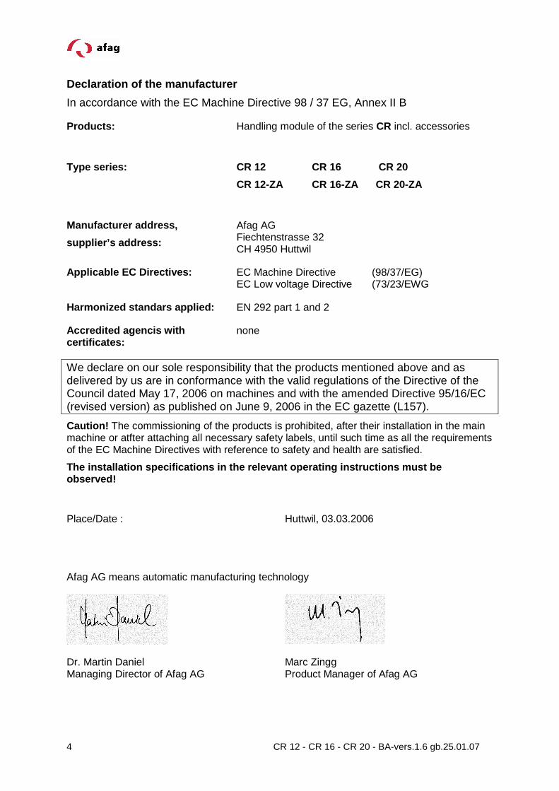
Declaration of the manufacturer
In accordance with the EC Machine Directive 98 / 37 EG, Annex II B
Products: Handling module of the series CR incl. accessories
Type series:
CR 12 CR 16 CR 20
CR 12-ZA CR 16-ZA CR 20-ZA
Manufacturer address,
supplier’s address:
Afag AG Fiechtenstrasse 32 CH 4950 Huttwil
Applicable EC Directives: EC Machine Directive (98/37/EG) EC Low voltage Directive (73/23/EWG
Harmonized standars applied: EN 292 part 1 and 2
Accredited agencis with certificates:
none
We declare on our sole responsibility that the products mentioned above and as delivered by us are in conformance with the valid regulations of the Directive of the Council dated May 17, 2006 on machines and with the amended Directive 95/16/EC (revised version) as published on June 9, 2006 in the EC gazette (L157).
Caution! The commissioning of the products is prohibited, after their installation in the main machine or atfter attaching all necessary safety labels, until such time as all the requirements of the EC Machine Directives with reference to safety and health are satisfied.
The installation specifications in the relevant ope rating instructions must be observed!
Place/Date : Huttwil, 03.03.2006
Afag AG means automatic manufacturing technology
Dr. Martin Daniel Managing Director of Afag AG
Marc Zingg Product Manager of Afag AG

5 CR 12 - CR 16 - CR 20 - BA-vers.1.6 gb.25.01.07
Description CR
Description CR-ZA
1
2
3
4
5
Flanged shaft
Drive piston
Stop screw AS
Shock absorber SD
Lock-nut the shock absorber
6
7
8
9
10
Clamping screw
Clamping plate
Positions pis of intermediate stop ZA
Lock-nuts for positioning pin
Housing ZA
6 CR 12 - CR 16 - CR 20 - BA-vers.1.6 gb.25.01.07
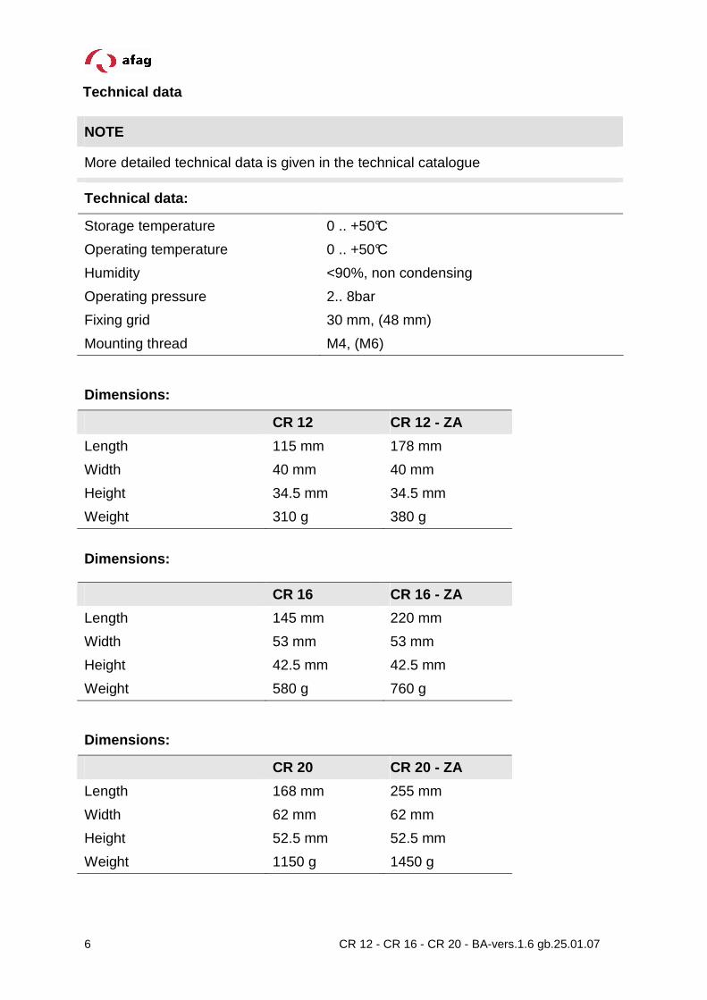
Technical data
NOTE
More detailed technical data is given in the technical catalogue
Technical data:
Storage temperature 0 .. +50°C
Operating temperature 0 .. +50°C
Humidity <90%, non condensing
Operating pressure 2.. 8bar
Fixing grid 30 mm, (48 mm)
Mounting thread M4, (M6)
Dimensions:
CR 12 CR 12 - ZA
Length 115 mm 178 mm
Width 40 mm 40 mm
Height 34.5 mm 34.5 mm
Weight 310 g 380 g
Dimensions:
CR 16 CR 16 - ZA
Length 145 mm 220 mm
Width 53 mm 53 mm
Height 42.5 mm 42.5 mm
Weight 580 g 760 g
Dimensions:
CR 20 CR 20 - ZA
Length 168 mm 255 mm
Width 62 mm 62 mm
Height 52.5 mm 52.5 mm
Weight 1150 g 1450 g

7 CR 12 - CR 16 - CR 20 - BA-vers.1.6 gb.25.01.07
Transport and storage
The module should be stored dry in the transport packing. The module must be packed in such a way that it is protected from impacts and dust.
Operating conditions (maintenance and servicing)
Under the following conditions the rotary modules are maintenance-free:
- clean workshop atmosphere
- no splash water
- no dust and fumes caused by abrasion or processes
- ambient conditions according to the technical catalogue
The module should be cleaned with a dry cloth at regular intervals.
The module must not be washed down; do not use any aggressive cleaners.
8 CR 12 - CR 16 - CR 20 - BA-vers.1.6 gb.25.01.07
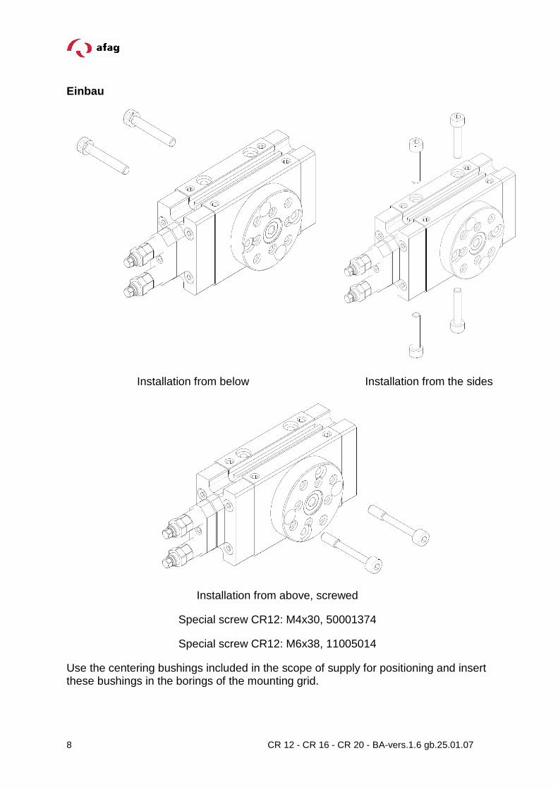
Einbau
Installation from below Installation from the sides
Installation from above, screwed
Special screw CR12: M4x30, 50001374
Special screw CR12: M6x38, 11005014
Use the centering bushings included in the scope of supply for positioning and insert these bushings in the borings of the mounting grid.

9 CR 12 - CR 16 - CR 20 - BA-vers.1.6 gb.25.01.07
WARNING
The CR-Modul must only be operated and maintaine by persons who are aware of and who have been instructed in the dangers.
NOTE
The CR-module has been built according to the present state-of-the-art and the recognized rules of technical safety. In spite of that it’s operation may lead to dangers to life and limb of the user, damage to property or impair the function of the rotary module.
The CR-modules are exclusively designed for rotary movements in any position with a torque of 0.45 Nm for the CR 12, 1.25 Nm for the CR 16 and 2.2 Nm for the CR 20, which do not represent any danger to persons, property and the environment during their operation.
Any other use is regarded as inadequate.
The manufacturer does not accept any liability for damage resulting from such use. The risk is that of the user alone.
The screws to be used for the assembly must at least satisfy the following conditions:
Standard: VDI 2230 Strength: class 8.8 Surface: galvanized blue, oiled or greased Thread Torque
M3 1,1 … 1,3 Nm
M4 2,5 … 2,9 Nm
M5 4,9 … 5,8 Nm
M6 8,5 ... 9,9 Nm
10 CR 12 - CR 16 - CR 20 - BA-vers.1.6 gb.25.01.07
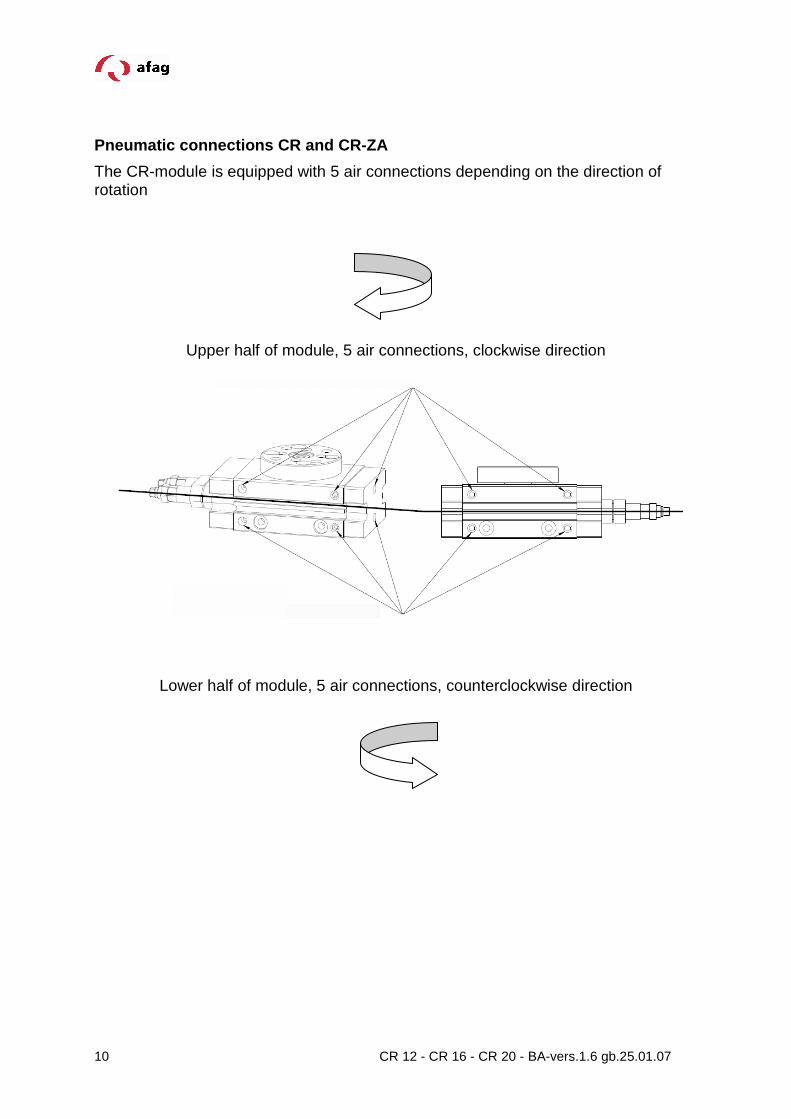
Pneumatic connections CR and CR-ZA
The CR-module is equipped with 5 air connections depending on the direction of rotation
Upper half of module, 5 air connections, clockwise direction
Lower half of module, 5 air connections, counterclockwise direction

11 CR 12 - CR 16 - CR 20 - BA-vers.1.6 gb.25.01.07
Pneumatic connection for Module CR
1 Compressed air connection 4 One-way restrictor
2 Maintenance unit 5 CR-rotary module
3 4/2 port directional control valve
5
4
3
1 2
12 CR 12 - CR 16 - CR 20 - BA-vers.1.6 gb.25.01.07
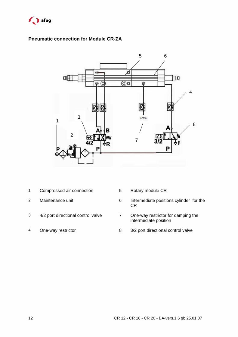
Pneumatic connection for Module CR-ZA
1 Compressed air connection 5 Rotary module CR
2 Maintenance unit 6 Intermediate positions cylinder for the CR
3 4/2 port directional control valve 7 One-way restrictor for damping the intermediate position
4 One-way restrictor 8 3/2 port directional control valve
7
5 6
4
8
3 1
2
13 CR 12 - CR 16 - CR 20 - BA-vers.1.6 gb.25.01.07
Preparation for start-up
Set the shock absorber and the stop screw in such a way that the stroke is properly damped before starting the rotary module.
CAUTION
The rotary module is a precision-mechanical device which must be transported and stored as well as operated, adjusted and assembled with utmost care.
First start-up
� Ventilate the total system slowly.
� Note the permissible values (see catalogue) regarding:
- useful load - motion frequency - mechanical load
WARNING
Limbs may be squeezed by moving components.
� Make sure that there are no persons or tools within the operative range of the module.
� Carry out a test run
- first of all at slow traverse speed - afterwards under operating conditions
14 CR 12 - CR 16 - CR 20 - BA-vers.1.6 gb.25.01.07
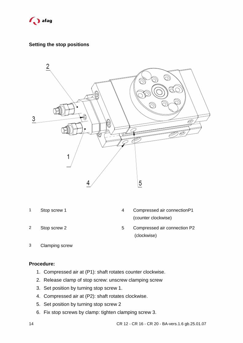
Setting the stop positions
1 Stop screw 1 4 Compressed air connectionP1
(counter clockwise)
2 Stop screw 2 5 Compressed air connection P2
(clockwise)
3 Clamping screw
Procedure:
1. Compressed air at (P1): shaft rotates counter clockwise.
2. Release clamp of stop screw: unscrew clamping screw
3. Set position by turning stop screw 1.
4. Compressed air at (P2): shaft rotates clockwise.
5. Set position by turning stop screw 2
6. Fix stop screws by clamp: tighten clamping screw 3.

15 CR 12 - CR 16 - CR 20 - BA-vers.1.6 gb.25.01.07
Angle of rotation
Maximum angle of rotation = 196°
Reduction of angle rotation
Starting from a position between 0° and 180° the li mit positions can be reduced by maximum 95° by screwing in the corresponding stop s crew.
CAUTION
If the angle of rotation is reduced by much more than 95° air may leak for constructional reasons. Turn the stop screw back to remove the leakage.
16 CR 12 - CR 16 - CR 20 - BA-vers.1.6 gb.25.01.07
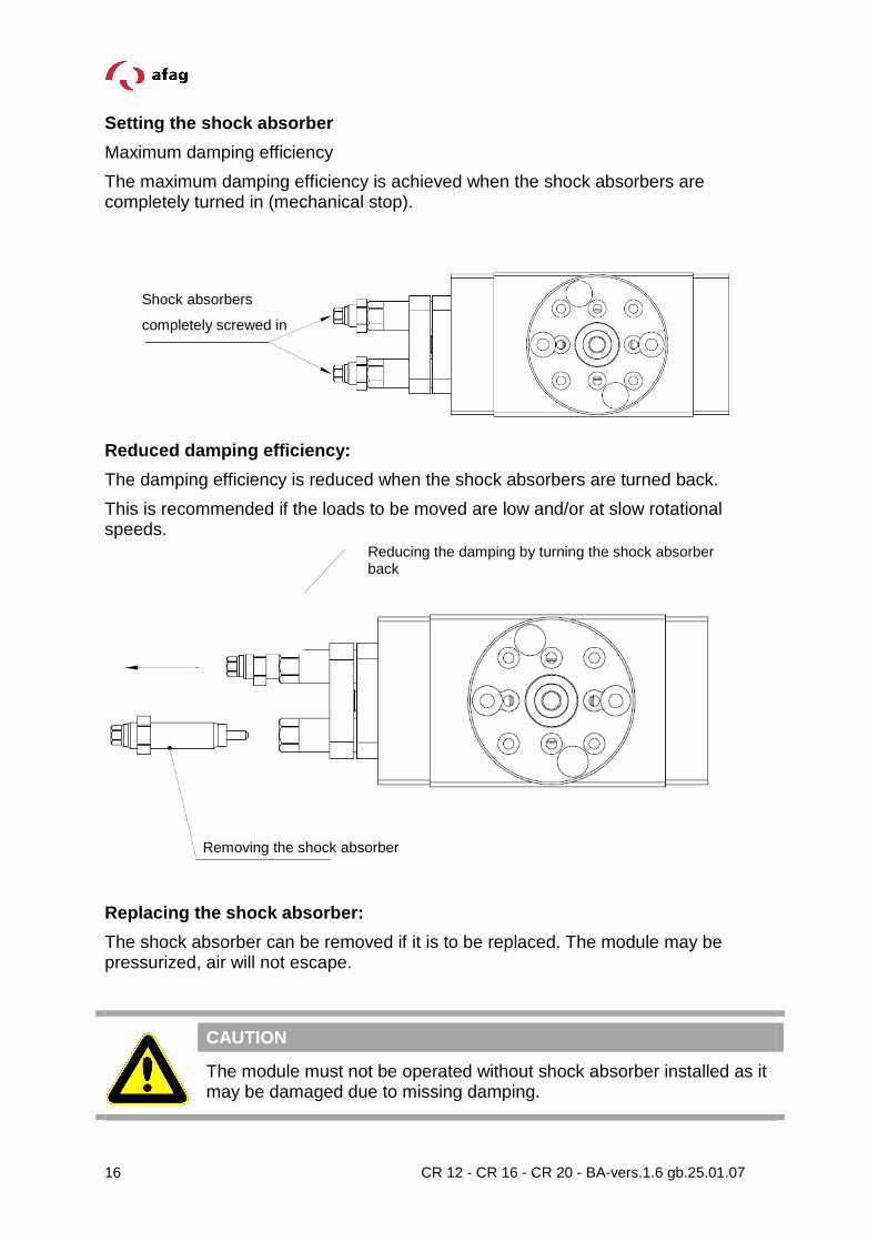
Setting the shock absorber
Maximum damping efficiency
The maximum damping efficiency is achieved when the shock absorbers are completely turned in (mechanical stop).
Reduced damping efficiency:
The damping efficiency is reduced when the shock absorbers are turned back.
This is recommended if the loads to be moved are low and/or at slow rotational speeds.
Replacing the shock absorber:
The shock absorber can be removed if it is to be replaced. The module may be pressurized, air will not escape.
CAUTION
The module must not be operated without shock absorber installed as it may be damaged due to missing damping.
Reducing the damping by turning the shock absorber back
Removing the shock absorber
Shock absorbers
completely screwed in
17 CR 12 - CR 16 - CR 20 - BA-vers.1.6 gb.25.01.07
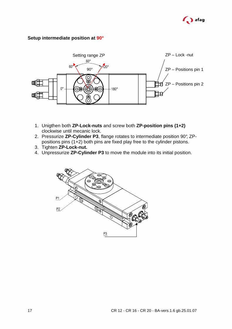
Setup intermediate position at 90°
1. Unigthen both ZP-Lock-nuts and screw both ZP-position pins (1+2) clockwise until mecanic lock.
2. Pressurize ZP-Cylinder P3 , flange rotates to intermediate position 90°, ZP-positions pins (1+2) both pins are fixed play free to the cylinder pistons.
3. Tighten ZP-Lock-nut. 4. Unpressurize ZP-Cylinder P3 to move the module into its initial position.
ZP – Lock -nut
ZP – Positions pin 1
ZP – Positions pin 2
Setting range ZP
90°

18 CR 12 - CR 16 - CR 20 - BA-vers.1.6 gb.25.01.07
Sample: Setup intermediate position at 75°
Sequence:
Setup ZP-angle as described:
In order to setup intermediate position at 75° module has to be prepared. Pressuize P1 and P3 and make sure module is at 90° position.
Setup intermediate position to 75° by adjusting ZP-positions pin (2). ZP-positions pin (2) is initially cpmpletely screw in.
1. Unigthen ZP-Lock-nut (2). Use a 9 mm open-jaw-wrench to open about ½ rotation.
2. Screw ZP-positions pin (2) counter-cklockwise until flange arrives at 75°. 3. Tigthen ZP-Lock-nut (2) again.

19 CR 12 - CR 16 - CR 20 - BA-vers.1.6 gb.25.01.07
Sample: Setup 2 intermediate position at 110°
Sequence:
Module is pressurized at P1 and P3:
1. Starting condition: flange is at intermediate position 1 at 75° 2. Unigthen ZP-Lock-nut (1) . Use a 9 mm open-jaw-wrench to open abaout ½
rotation.
3. Use allen key to screw ZP positions pin (1) counter-clockwise until flange arrives at 110°
4. Tigthen ZP-Lock-nut (1) again

20 CR 12 - CR 16 - CR 20 - BA-vers.1.6 gb.25.01.07
Use this sequence to move between the positions:
Sequence: Start at 0°
1. From 0° to 75° Pressurize P3 (ZP-cylinder )
2. From 75° to 110° Pressurize P1
3. From 110° to 180° Unpressurize P3 (ZP-cylinder )
4. From 180° to 0° Unpressurize P1
21 CR 12 - CR 16 - CR 20 - BA-vers.1.6 gb.25.01.07
Polling the sensors
Clamping magnetic field sensors (1) are used for polling the CR stop positions.
CAUTION
The CR and the initiators must not be used in an explosion-hazardous area.
NOTE
The magnetic field sensors are not included in the scope of supply of the CR-module (please see technical catalogue).
CAUTION
Only the specified proximity switches are to be used.
Polling of the stop positions is monitored by an LED on the initiator. If the LED switch status does not change during polling the sensor is faulty and must be replaced!
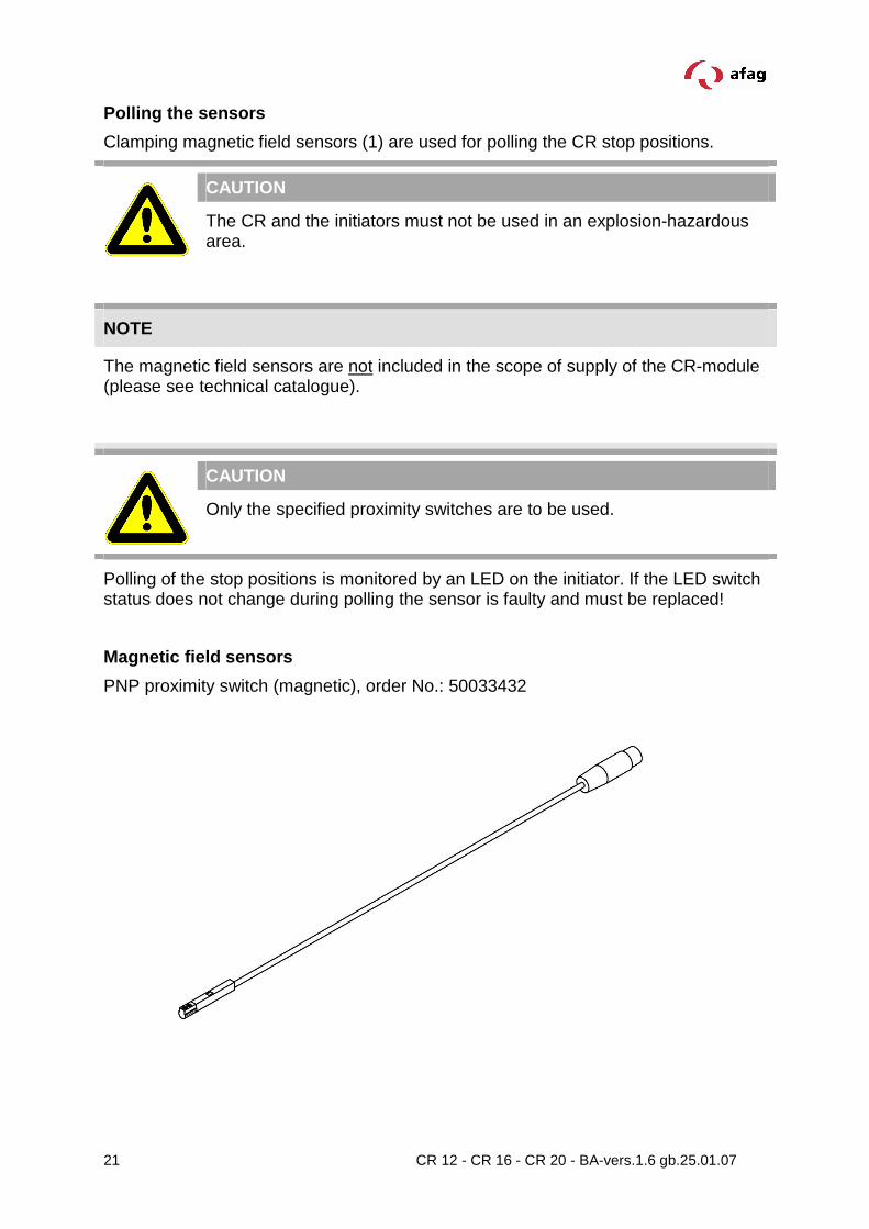
Magnetic field sensors
PNP proximity switch (magnetic), order No.: 50033432

22 CR 12 - CR 16 - CR 20 - BA-vers.1.6 gb.25.01.07
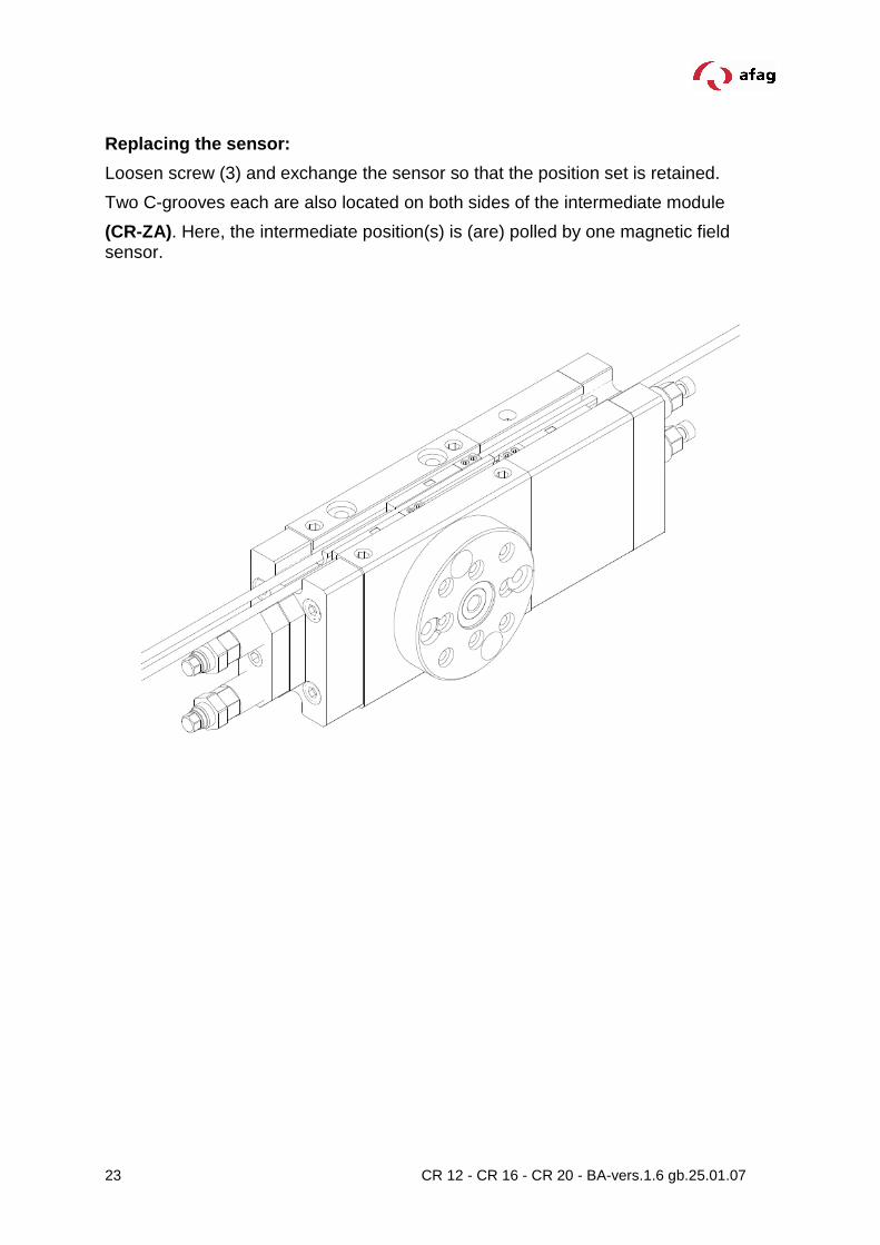
Sensor installation
The magnetic field sensors (accessories) are mounted in 2 C-grooves which are located on each side of the module (CR-module) . These magnetic field sensors are used to poll the stop positions.
1 Sensor 3 Screw for fastening the sensor holder in the groove
2 Screw for fastening the sensor in the sensor holder
4 Slut nut
Attaching the sensors
1. Insert sensors (1) with sensor holder in the C-grooves.
2. Fasten sensor with screw (3) in the C-groove.
3. Connect sensor to controller.
4. Check proper function of the sensors.
3
1
2
Detail X
4
X
23 CR 12 - CR 16 - CR 20 - BA-vers.1.6 gb.25.01.07
Replacing the sensor:
Loosen screw (3) and exchange the sensor so that the position set is retained.
Two C-grooves each are also located on both sides of the intermediate module
(CR-ZA). Here, the intermediate position(s) is (are) polled by one magnetic field sensor.
24 CR 12 - CR 16 - CR 20 - BA-vers.1.6 gb.25.01.07
Maintenance
The CR-Module is lifetime lubricated, it can be driven with oiled or oil-free air.
CAUTION
Under no circumstances must the CR be operated with oiled air before operating with oil.free air!
Air specification:
� Dry (free of condensation)
� filtered (40um filter for oiled air)
� filtered (5 um filter for oiled air)
If the CR is to be operated with oiled air, then the following oils are recommended:
• Festo Special oil
• Avia Avilub RSL 10
• BP Energol HPL 10
• Esso Spinesso 10
• Shell Tellus Oel C 10
• Mobil DTE 21
• Blaser Blasol 154
Amount of oil: 5-10 drops of oil per 1000 l air
Viscosity range:
9 bis 11 mm2/s (= cST) bei 40°C, ISO-classe VG 10 a ccording to ISO 3448
Apart from the usual cleaning work no further maintenance measures are required.
CAUTION
Module inserts for ionized air environments (e.g.in case of high-voltage procedure such has corona processes).
Open guides and flange should be covered with a grease layer to avoid any rust.
Recommendation: Clean and grease once a month!
Afag standard: - Staburax NBU8EP (lat guides)
- Blasolube 301 (piston rods)
25 CR 12 - CR 16 - CR 20 - BA-vers.1.6 gb.25.01.07
Disassembly and Repair
When the module is damaged it may be returned to Afag AG for repair:
WARNING
The module may only be disassembled when the system is ventilated and deactivated. If pneumatic connections are disconnected when they are under pressure, this may result in serious personal injury owing to fast movements of moving parts.
Accessories of theCR 12
Item Order No.
Special screw M4x30 mm 50001374
Proximity switch PNP prep tenon block 50033432
Assessories of theCR 16 / CR 20
Item Order No.
Special screw M6x38 mm 11005014
Proximity switch PNP with sliding block 50033432
26 CR 12 - CR 16 - CR 20 - BA-vers.1.6 gb.25.01.07
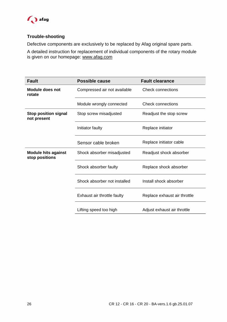
Trouble-shooting
Defective components are exclusively to be replaced by Afag original spare parts.
A detailed instruction for replacement of individual components of the rotary module is given on our homepage: www.afag.com
Fault Possible cause Fault clearan ce
Module does not rotate
Compressed air not available
Module wrongly connected
Check connections
Check connections
Stop position signal not present
Stop screw misadjusted
Initiator faulty
Sensor cable broken
Readjust the stop screw
Replace initiator
Replace initiator cable
Module hits against stop positions
Shock absorber misadjusted
Shock absorber faulty
Shock absorber not installed
Exhaust air throttle faulty
Lifting speed too high
Readjust shock absorber
Replace shock absorber
Install shock absorber
Replace exhaust air throttle
Adjust exhaust air throttle

27 CR 12 - CR 16 - CR 20 - BA-vers.1.6 gb.25.01.07
Disposal
CR which are of no further use should not be disposed of as a complete unit but dismantled into individual parts according to the type of material and recycled should be correctly disposed of.

28 CR 12 - CR 16 - CR 20 - BA-vers.1.6 gb.25.01.07
Afag Automation AG Fiechtenstrasse 32 CH - 4950 Huttwil Switzerland
Tel.: +41 (0)62 959 86 86
Fax.: +41 (0)62 959 87 87
e-mail: [email protected]
Internet: www.afag.com