Course Introduction - Freescale Semiconductor
33
Purpose • The intent of this course is to provide an overview of the MC9S12NE64 16-bit MCU. Objectives • Describe the main features of the NE64. • Identify derivative availability. • Describe the Ethernet Media Access Controller (EMAC). • Describe the Ethernet Physical Transceiver (EPHY). • Relate their functions and capabilities to the IEEE 802.3 standard. • Describe the development tools environment. Content • 32 pages • 6 questions Learning Time • 50 minutes Course Introduction Welcome to the MC9S12NE64 Certification Training Course. The intent of this course is to provide an overview of the MC9S12NE64 (NE64) 16-bit MCU. The 128K and 256K versions will be offered with 32 bit solution and will not be part of the NE family. You will learn about the key features of this device, its available derivatives, the ever essential development tools environment available to support this device, and future derivatives of this device. You will also learn about the Ethernet Physical Interface (EPHY) and the Ethernet Medium Access Controller (EMAC) and how they work to implement the IEEE 802.3 standard. Finally, you will gain an understanding of the targeted applications for this technology.
Transcript of Course Introduction - Freescale Semiconductor

1
Purpose• The intent of this course is to provide an overview of the
MC9S12NE64 16-bit MCU.
Objectives • Describe the main features of the NE64.• Identify derivative availability. • Describe the Ethernet Media Access Controller (EMAC).• Describe the Ethernet Physical Transceiver (EPHY).• Relate their functions and capabilities to the IEEE 802.3 standard.• Describe the development tools environment.
Content• 32 pages• 6 questions
Learning Time• 50 minutes
Course Introduction
Welcome to the MC9S12NE64 Certification Training Course. The intent of this course is to provide an overview of the MC9S12NE64 (NE64) 16-bit MCU. The 128K and 256K versions will be offered with 32 bit solution and will not be part of the NE family. You will learn about the key features of this device, its available derivatives, the ever essential development tools environment available to support this device, and future derivatives of this device. You will also learn about the Ethernet Physical Interface (EPHY) and the Ethernet Medium Access Controller (EMAC) and how they work to implement the IEEE 802.3 standard. Finally, you will gain an understanding of the targeted applications for this technology.

2
MC9S12NE64
PART NUMBER PACKAGE TEMP Orderable QTY’s
MC9S12NE64VTU 80 TQFP-EP -40 TO 105 C 90MC9S12NE64CPV 112 LQFP -40 TO 85 C 60
TEST CONTTEST CONT
88--ch 10ch 10--BitBitADCADC
V REGV REG
HCS12 CPUHCS12 CPU25 MHz25 MHz
44--ch 16ch 16--BitBitTIMERTIMER
64K64KFLASHFLASH
8K RAM8K RAM
CRGCRG
SPISPI
2 2 SCISCI
IICIIC
70 GPIO70 GPIO
10/100 10/100 BaseTBaseTEEPHYPHY
10/100 10/100 BaseT BaseT EEMACMAC
KBIKBIEXP BUS EXP BUS
I/FI/FBDMBDM
Let’s begin with an overview of the NE64 MCU, one of many derivatives available in the HCS12 portfolio of 16-bit MCUs. This device has full 16-bit data paths throughout and contains a wide variety of highly configurable memory and peripheral options. It is intended to provide a single-chip solution with a minimum number of external components in a wide variety of low cost, end node connectivity applications.
The 10/100 BaseT EMAC and the 10/100 BaseT EPHY are two differentiated features in this device. We will discuss these features in greater detail later in this course.
The NE64 device is offered in two package options. Option one is the 80-pin Thermally Enhanced Quad Flat Pack (TQFP). Samples can be ordered with two devices per kit or in production quantities of 90 devices per tray. This option has a total of 38 general purpose input/output (GPIO) pins, as well as 10 dedicated Input-only pins available to the user. Port pins that are not bonded out in this package should be initialized as inputs with enabled pull-up resistance to minimize excess current consumption.
Option one has an exposed flag for additional heat dissipation. This should be accommodated during PCB layout by either a hatched pattern in the solder mask or by providing small copper areas under the flag. At least 50 percent of the total area of the flag should be soldered to the PCB to ensure adequate heat dissipation for this extended temperature (-40°C to 105°C) package.
Option two is the 112-pin Low Profile Quad Flat Pack (LQFP). Samples can be ordered with two devices per kit or in production quantities of 60 devices per tray. This package has more pins available, which can support an expanded bus interface. This option has up to 70 GPIO pins, as well as 10 dedicated Input-only pins available to the user.
We will describe the other blocks in greater detail later.

3
NE64 FeaturesMouse over each peripheral to learn more.
16-bit HCS12 CPU (25MHz)•Upward compatible with M68HC11 instruction set•Interrupt stacking and programmer’s model identical to HC11/HC12•20-bit ALU
64KB Flash Memory•Organized as 1024 rows of 64 bytes•Erase sector size is 8 rows (512 bytes)
Shared RAM•Zero wait state accesses; (supports single-cycle misaligned word accesses without wait states)•When the EMAC module is enabled, functions as the FIFO buffer (S/W selectable from: .375K to 4.5K)•Allows same cycle read/write access from the CPU and the EMAC•ENET FIFO is configured as 1 Transmit and 2 Receive Buffers (A&B)
Clocks and Reset Generator Module (CRG)•PLL frequency multiplier•Self clock in absence of reference clock
Multiplexed Expanded Bus Interface (MEBI)•Available only in the 112-pin package at a specified maximum bus speed of 16 MHz•For external bus speeds of 2.5 MHz to 16 MHz; only 10BaseT communication is supported•Multiplexed address and data (16-bit wide and 8-bit narrow bus modes)•Ability to enable/disable pull-up resistors and enable/disable reduced output drive on Ports A,B,E, and K•Supports a number of modes of operation including various emulation, special test and peripheral modes
1 Synchronous Serial Peripheral Interface (SPI)• Master mode and slave mode• Serial clock with programmable polarity and phase
2 Asynchronous Serial Communications Interfaces ( 2 SCI)• 13-bit baud rate selection• Programmable 8- or 9-bit data format• Selectable IrDA1.4 return-to-zero-inverted (RZI) format with programmable pulse widths
Inter-IC Bus (IIC)• Two-wire bi-directional serial bus providing a simple effective method of data exchange• Minimizes the need for large number of connections• Eliminates the need for an address decoder
10/100 Mbps Ethernet Media Access Controller (EMAC)• Media Independent Interface (MII) with data management• Full-duplex flow control• Two receive buffers and One transmit buffer• Packet filtering to lower burden on MCU
– Address recognition filtering – EtherType filtering
• Auto speed selection (auto negotiation)• Full-/half- duplex modes (auto negotiation)• Direct connection to socket/transformer• For 10BaseT operation, the internal bus clock must be >2.5 MHz• For 100BaseT operation, the internal bus clock must be 25 MHz
10/100 Mbps Ethernet Physical Transceiver (EPHY)• Requires a minimum number of external components• For basic operation, the Reference Clock to the EPHY must be 25MHz (spec’d at 25ppm)
Up to 70 I/O and 10 Inputs• Each I/O pin can be configured by by several registers: Input/Output selection, drive strength reduction
select of pull up/pull down resistors, interrupt enable and status flags. • Some pins have optional features such as Open drain for wired-or connections and interrupt inputs with
Analog-to-Digital Converter (ADC)• Flexible 8-channel module with 10-bit resolution• Supports external conversion trigger capability
Timer Module (TIMER)• PLL frequency multiplier• Self clock in absence of reference clock
Port Integration Module (PIM)• Establishes the interface between the peripheral modules and the input/output (I/O) pins for all ports• Input/Output selection, Pull up/Pull down selection, drive strength selection, etc.
Voltage Regulator (V REG)• Provides 5 independent 2.5V output voltages from a 3.3V +/- 5 % input voltage• Three modes of operation: full power, reduced power, shutdown• Includes the Low Voltage Reset (LVR) and Power On Reset (POR) functions
TEST CONTTEST CONT
88--ch 10ch 10--BitBitADCADC
V REGV REG
HCS12 CPUHCS12 CPU25 MHz25 MHz
44--ch 16ch 16--BitBitTIMERTIMER
64K64KFLASHFLASH
8K RAM8K RAM
CRGCRG
SPISPI
2 2 SCISCI
IICIIC
70 GPIO70 GPIO
10/100 10/100 BaseTBaseTEEPHYPHY
10/100 10/100 BaseT BaseT EEMACMAC
KBIKBIEXP BUS EXP BUS
I/FI/F BDMBDM
Let’s take a look at the main features of the NE64. Roll your mouse pointer over each peripheral for more information.
4
Which of the following communications interfaces are available on board the NE64? Select all that apply and then click Done.
SPI
CAN
IIC
SCI
10/100 EMAC
10/100 EPHY
QuestionQuestion
Consider this question regarding the NE64’s basic feature set.
Correct.
The NE64 includes a number of integrated peripheral interfaces to simplify system design and components count for users. SPI, IIC, SCI, 10/100 EMAC, and 10/100 EPHY are all available as integrated peripheral interfaces on the NE64. The Controller Area Network (CAN) is not one of the communications interfaces available on the NE64.

5
NE64 Flash Memory
Now, let’s examine the NE64’s Flash memory in more detail.
The NE64 utilizes a 64-KB, .25µm Flash array, which offers automated program and erase algorithms. It is not possible to read from the Flash block while it is being programmed or erased. Cumulative programming of bits within a word are not allowed in the FTS64K Flash block, that is, a word must be erased before being programmed. The Flash array can be globally secured (protected). Additionally, two smaller sectors at the low and high end of Flash memory can be secured for critical data, like boot loader code.
The Flash array uses the oscillator clock to perform Flash program or erase operations. The internal Flash clock frequency must be configured to run between 150 KHz and 200 KHz.
The Clock Divider allows the user to divide down the oscillator clock to the desired range.

6
NE64 CRG ModuleClick the “Registers” block to
learn about the flags in the CRGFLG register.
Let’s take a few minutes to examine the NE64’s CRG module. In order for the NE64 to operate properly as an Ethernet device, the Phase-Locked Loop (PLL) should be selected, that is, the PLLSEL bit must be set. The SYSCLK must be configured to 25 MHz.
As you can see from the block diagram, programming the CRG module can be challenging and time consuming. Processor Expert™ can be used within (or independent of) the CodeWarrior Integrated Development Environment (IDE) to simplify programming the CRG module and any other resource/module that must be software configured before it can be used on the NE64.
A number of useful timing- and voltage-derived interrupts and resets are generated from this module. In addition to the physical signals, a number of flags are indicated in the CRG Flags Register (CRGFLG) within the registers block. Click the “Registers” block to learn about some of these flags.
On the next page, we will examine how the physical clocks from the CRG are distributed to the rest of the NE64.

7
NE64 Clock Tree
Note that the CRG module generates three fundamental clocks to the remainder of the device: the core clock, the IPBus clock, and the OSCCLK.
The IPBus clock is distributed synchronously to all of the on-chip peripherals as well as the S12 core and Flash module. Each IPBus peripheral has the ability to further divide (scale) the IPBus clock to achieve the appropriate timing for its requirements.
It is very simple to configure these internal peripherals using Processor Expert™ instead of having to comprehend the many configuration and control registers and their associated equations.

8
Question
The MC9S12NE64 includes a 64 KB Flash memory module. Can individual bits be cumulatively updated within a Flash word? Select the correct answer and then click Done.
YesNo
Try this question, which tests your knowledge of the NE64’s basic feature set.
Correct.
Cumulative programming of bits within a word is not allowed in the FTS64K Flash block. A word must be erased before being programmed, even if it is a bit that has not yet been programmed since the last erasure.

9
Router
Ethernet End Node
LAN_2
HUB(s)
LAN_1
HUB(s)
Router
Router Router
Internet
MC9S12NE64
PC Host
MC9S12NE64
MC9S12NE64
MC9S12NE64
MC9S12NE64
PC Host
CrossoverCable
Mouse over LAN, HUB, and router to
learn more.
A local area network (LAN) is simply a collection of PCs and other peripheral (embedded) devices connected at one physical location by a shared medium. The choice of medium determines the lengths and types of cables and interconnect and thereby the physical dimensions of the LAN.
Let’s take a moment to review the bigger picture and see how the NE64 fits into the world of communications networks. We will begin with some network terminology to better understand the purpose and differentiated features of the NE64. Roll your mouse pointer over LAN, HUB, and router for a definition of each.
Most communications networks use physical star topologies for reliability and ease of adding/removing nodes. A star topology is a physical implementation in which all network connections pass through a central device, typically called a concentrator. A bus topology is a physical implementation in which all devices are serially connected to the same length of cable. The NE64 supports both star and bus physical topologies.
In this diagram, the NE64s are represented as end nodes. Clearly, end nodes can be simple or complex. When two end nodes are connected directly to each other without going through another device (like a HUB), it is necessary to use a Crossover cable. Crossover cables swap twisted pairs 2 and 3 (TX and RX) so the end nodes can talk to each other. As you might surmise, connecting two HUBs directly would also require a crossover cable.
The NE64 is designed to operate in wired LAN configurations. In this environment, the most common communications medium is Category 5 (CAT5) unshielded, twisted pair (UTP) cable. Ethernet, a LAN topology based on a methodology called Carrier Sense Multiple Access/Collision Detection (CSMA/CD), is commonly used in LANs for device connectivity because it is inexpensive and maintains high throughput with cable lengths of up to 100M.
Later, we will look at the format and content of an Ethernet packet in order to understand its structure. Right now, let’s take a look at some Ethernet network end node functions and NE64 applications.

10
NE64 End Node Applications
• Lowest cost Ethernet applications
• Applications where connectivity has not been considered viable in thepast due to cost of implementation
• Applications where space constraints make two to three chip solutionsunacceptable
• Applications where single-chip reliability is essential
• Applications where electromagnetic emissions/susceptibility areof concern
Here you can see that the NE64 is an exceptional solution for price-sensitive applications, real estate constrained solutions, applications where single-chip reliability is essential to achieve mean time before failure, and applications where a single-chip implementation provides for a more robust system in terms of electromagnetic compatibility due to reduced external interconnects (exposed routing wires act as antennas).
End node functions may include Web servers, industrial monitoring or control systems, and commercial monitoring or control systems as well as many other applications. Click “Applications” to see a list of network end node applications.
11
Applications
• Web servers*• Internet-enabled devices• Remote monitoring via the Web (data collection/diagnostics)• Remote control of devices in the field via the Web• Remote devices that send messages via email or text pagers• Remote reprogramming/updates of Applications Flash via the Web
*It is important not to confuse the Web server mentioned here, which is capable of serving up to a few pages, with a network server. Network servers require large storage capacities and fast processors. This would not be a good match for the NE64. The NE64 can serve as a maintenance monitor for a network server by monitoring power supplies, ambient temperature, door closure, fan status, etc. and report this information through a variety of methods including Web page and email.
Reference Material for previous page

12
Question
The MC9S12NE64 would be a good candidate for which of the following target applications? Select all that apply and then click Done.
End node on a LANEthernet HUBWeb serverGateway controllerRouter
Consider this question about the NE64’s applicability in various products.
Correct.
The NE64 would be a good candidate for both an end node on a LAN and a Web server.

13
TCP/IP Stack Model
Now, we will look more closely at Transmission Control Protocol/Internet Protocol (TCP/IP) stacks and protocols, the Ethernet and its packet format, and the on-chip capabilities of the NE64 to support the IEEE 802.3 standard.
TCP/IP is the collection of protocols that are responsible for carrying data over the Internet. The Open Systems Interconnect (OSI) model is shown in relation to the TCP/IP model.
TCP/IP is an open standard created by the Internet Engineering Task Force (IETF). Standards created by IETF committees are shared with the networking community at large by sets of documents called Requests For Comments (RFCs).
Address Resolution Protocol (ARP) relates IP addresses to their respective hardware MAC addresses.

14
TCP/IP Protocols
A TCP/IP protocol stack defines a set of protocols that allows network devices to connect to other specified devices on a network so they can exchange data. These protocols are defined by RFCs and enable embedded devices like the NE64 to send email, serve Web pages, transfer files, and perform a variety of other functions we associate with basic connectivity. This table illustrates some of TCP/IP’s more common protocol stacks and their functions.
TCP guarantees delivery by network handshaking and formation of a TCP connection between devices. User datagram protocol (UDP) by contrast, is considered connectionless and is used in simple network applications where the occasional missed message is not harmful.

15
Ethernet: CSMA/CD
CS: All Ethernet interfaces monitor the medium for activity. If it is idle, they may transmit a frame.
MA: All Ethernet interfaces have equal access to the medium. No station should be able to get a higher priority than another station.
CD: Since signals take a finite time to travel from one end of an Ethernet system to the other, the first bits of a transmitted frame do not reach all parts of the network simultaneously. It is possible for two interfaces to sense that the network is idle and to start transmitting their frames simultaneously. When this happens, the Ethernet system has a way to sense the collision of signals and to stop the transmission and resend the frames.
The CSMA/CD protocol provides fairaccess to the shared channel so thatall stations get a chance to use thenetwork. After every packet is sent,all stations use CSMA/CD to determinewhich station gets to use the channel next.
Mouse over each part of the protocol to learn more.
CSCarrier Sense (Is someone already talking?)
MAMultiple Access (I hear what you hear!)
CDCollision Detection (Hey, we’re both talking!)
The CSMA/CD is defined by the IEEE 802.3 standard. The IEEE 802.3 standard defines the MAC sublayer for CSMA/CD and a corresponding physical layer for connection to base band coaxial cable and twisted-pair wiring. The standard is basically patterned after the Ethernet specification. Variations in the physical layer allow signaling rates of 1, 5, 10, and 100 Mbps, as well as 1 Gbps.
Roll your mouse pointer over each part of the protocol for more information.
Ethernet is a shared communications medium. Each device on the network must have a unique hardware address. Let’s take a look at the format of an Ethernet packet.

16
Ethernet Packet (Frame) Format
In an Ethernet network, information is received or transmitted in the form of a frame. The frame format used for Ethernet consists of the Preamble (PA), Start Frame Delimiter (SFD), Destination MAC Address (DA), Source MAC Address (SA), length/type field, data field, and Frame Check Sequence (FCS).
The frame length is defined to be 64 bytes minimum and 1518 bytes maximum, excluding the PA and SFD. If the length/type field is greater than 1536, this field identifies the type (EtherType) of the packet. The EtherType field identifies the higher level protocol used to create the encapsulated data. Like MAC addresses, EtherTypes are managed by the IEEE Registration Authority.
The data link layer is primarily concerned with message packaging and link management. It is largely independent of the medium-dependent physical channel. The message packaging function includes framing, which identifies the beginning and end of a message; addressing, which specifies fields for source and destination addresses; and error checking, which uses redundant codes to detect channel errors.
The message packaging function also includes the preamble. It consists of the repeating sequence 101010... for 8 bytes or 64 bits and announces the occurrence of the frame. Generation and removal of the preamble are functions of the physical layer. Similarly, the end of a frame is provided by the removal of the carrier sense signal, as detected by the absence of a bit transition following the last bit of the FCS. Note that frame sizes must contain an integral number of bytes, ranging from 72 to 1526 bytes—at 8 bits per byte, that’s 572 to 12,208 bits. The Type field is reserved to indicate which of several possible higher-level protocols might be in use.
For devices that exist on a closed (private) network, it is only necessary that each device be assigned a unique MAC address. For devices that need to communicate over the World Wide Web, each device must be assigned a unique MAC address, and the supplier of this device should obtain a block of MAC addresses from the IEEE Registration Authority.

17
IEEE 802.3 Standard Compliant
The NE64 is compliant with the IEEE 802.3 CSMA/CA standard and the 802.3, 802.3u, and 802.3x specifications. Operation can be 10 Mbps full duplex or half duplex and 100 Mbps full duplex or half duplex using an MII. The NE64 does not support 802.3z (Gigabit Ethernet).

18
Question
Which of the following IEEE 802.3 standards are NOT supported by the NE64? Select the correct answer and then click Done.
a. 802.3b. 802.3uc. 802.3xd. 802.3z
Here is a question that tests your knowledge of the NE64’s ability to support elements of the IEEE 802.3 standards.
Correct.
The NE64 is compliant with the IEEE 802.3 CSMA/CA standard and the 802.3, 802.3u, and 802.3x specifications. The NE64 does not support 802.3z (Gigabit Ethernet).
19
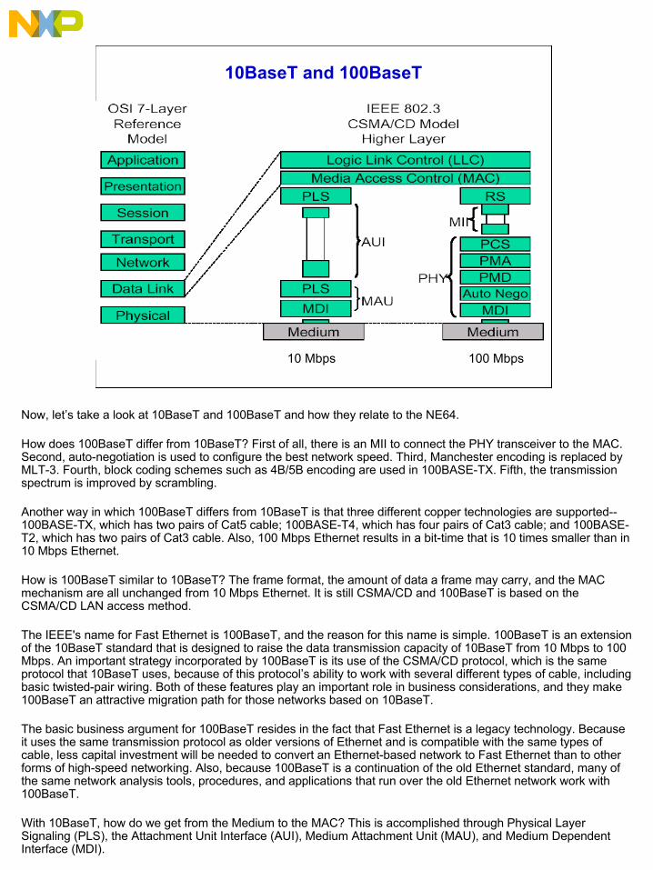
10BaseT and 100BaseT
10 Mbps 100 Mbps
Now, let’s take a look at 10BaseT and 100BaseT and how they relate to the NE64.
How does 100BaseT differ from 10BaseT? First of all, there is an MII to connect the PHY transceiver to the MAC. Second, auto-negotiation is used to configure the best network speed. Third, Manchester encoding is replaced by MLT-3. Fourth, block coding schemes such as 4B/5B encoding are used in 100BASE-TX. Fifth, the transmission spectrum is improved by scrambling.
Another way in which 100BaseT differs from 10BaseT is that three different copper technologies are supported--100BASE-TX, which has two pairs of Cat5 cable; 100BASE-T4, which has four pairs of Cat3 cable; and 100BASE-T2, which has two pairs of Cat3 cable. Also, 100 Mbps Ethernet results in a bit-time that is 10 times smaller than in 10 Mbps Ethernet.
How is 100BaseT similar to 10BaseT? The frame format, the amount of data a frame may carry, and the MAC mechanism are all unchanged from 10 Mbps Ethernet. It is still CSMA/CD and 100BaseT is based on the CSMA/CD LAN access method.
The IEEE's name for Fast Ethernet is 100BaseT, and the reason for this name is simple. 100BaseT is an extension of the 10BaseT standard that is designed to raise the data transmission capacity of 10BaseT from 10 Mbps to 100 Mbps. An important strategy incorporated by 100BaseT is its use of the CSMA/CD protocol, which is the same protocol that 10BaseT uses, because of this protocol’s ability to work with several different types of cable, including basic twisted-pair wiring. Both of these features play an important role in business considerations, and they make 100BaseT an attractive migration path for those networks based on 10BaseT.
The basic business argument for 100BaseT resides in the fact that Fast Ethernet is a legacy technology. Because it uses the same transmission protocol as older versions of Ethernet and is compatible with the same types of cable, less capital investment will be needed to convert an Ethernet-based network to Fast Ethernet than to other forms of high-speed networking. Also, because 100BaseT is a continuation of the old Ethernet standard, many of the same network analysis tools, procedures, and applications that run over the old Ethernet network work with 100BaseT.
With 10BaseT, how do we get from the Medium to the MAC? This is accomplished through Physical Layer Signaling (PLS), the Attachment Unit Interface (AUI), Medium Attachment Unit (MAU), and Medium Dependent Interface (MDI).

20
EPHY
Let’s take a look at the EPHY in more detail.
The EPHY is compliant with IEEE 802.3 specifications for 10BaseT (clause 14) operation up to 10 Mbps—called Ethernet—over UTP copper cable and 100BaseTX (clauses 24 and 25) PHY operation at 100 Mbps—called Fast Ethernet—over UTP and Cat5 UTP copper cable.
For basic operation, the reference clock to the EPHY must be 25 MHz and specified at 25 ppm.

21
PHY Sub Block
Here is a detailed diagram of the PHY sub block. You can see that both 10BaseT and 100BaseT share the same physical I/O connections and, in both cases, the connection interface to the EMAC is via the MII interface. However, the signals themselves take very different analog and digital pathways within the EPHY. 10BaseT utilizes Manchester encoding/decoding while 100BaseT uses 4B/5B encoding/decoding and MLT-3 scrambler/descrambler techniques.

22
A/N Advertisement Register
Mouse over each named bit field in the register to highlight the matching configurations.
NXTP Next Page Capability
RFLT Remote Fault
FLCTL Advertise that the device has implemented Flow Control
TAF100FD 100BASE-TX full duplex capable
TAF100HD 100BASE-TX half duplex capable
TAF10FD 10BASE-T full duplex capable
TAF10HD 10BASE-T full duplex capable
Selector Field(4:0) Initially set at “0001” to denote the device is IEEE 802.3 compliant
The Auto Negotiate (A/N) Advertisement Register determines which functional capabilities the EPHY advertises during the auto negotiate process with other devices on the network. These options are configurable. Roll your mouse pointer over each named bit field in the A/N Advertisement register to highlight the matching configurations.

23
Question
10BaseT and 100BaseT may show the same physical interface pins to the network, but their data rates, coding/decoding schemes, the signals that appear on the pins, etc. are very different. Which of the following techniques does 10BaseT use? Select the correct answer and then click Done.
a. 4B/5B encodingb. Manchester encodingc. MLT-3 scramblingd. 2B+D encoding
Here is a question that tests your knowledge of the NE64 EPHY.
Correct.
10BaseT utilizes Manchester encoding/decoding while 100BaseT uses 4B/5B encoding/decoding and MLT3 scrambler/descrambler techniques.
24
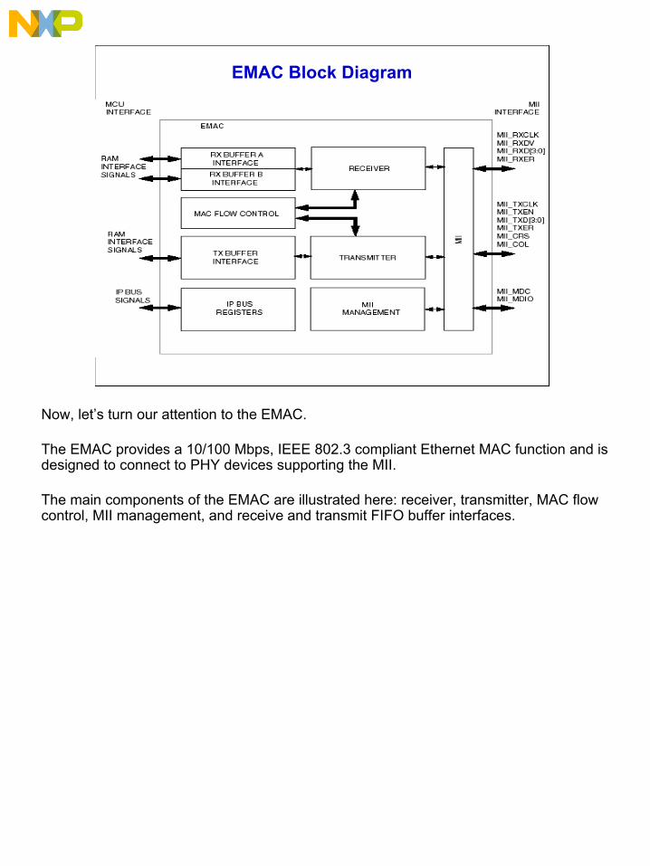
EMAC Block Diagram
Now, let’s turn our attention to the EMAC.
The EMAC provides a 10/100 Mbps, IEEE 802.3 compliant Ethernet MAC function and is designed to connect to PHY devices supporting the MII.
The main components of the EMAC are illustrated here: receiver, transmitter, MAC flow control, MII management, and receive and transmit FIFO buffer interfaces.

25
FIFO Buffer Configuration
The NE64 EMAC has a programmable FIFO buffer configuration. This allows flexibility in allocating RAM memory between the EMAC and system RAM.
Here you can see the 16-bit FIFO Buffer Configuration Register (BUFCFG). Three bits are allocated to selecting the FIFO Buffer Map (BUFMAP) and 11 bits are allocated to the Maximum Frame Length (MAXFL) in bytes. Values equal to or less than 64 decimals are treated as the minimum (64 decimals). Values equal to or greater than 1518 decimals are treated as the maximum (1518 decimals).
26
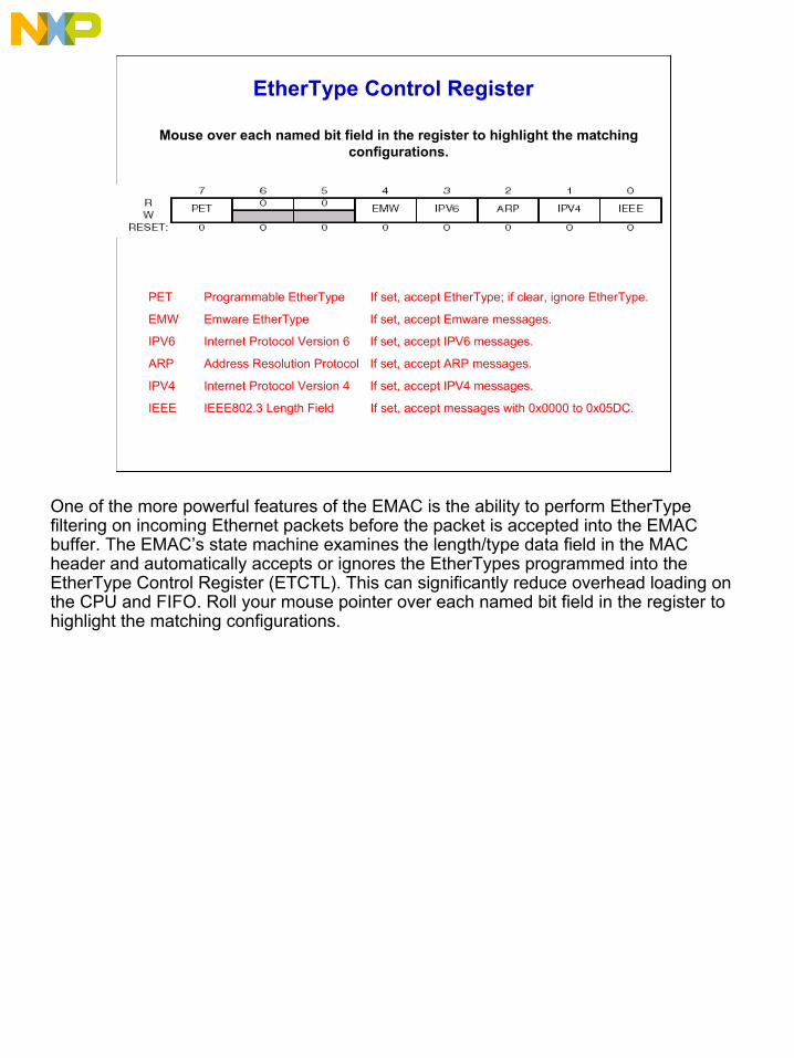
EtherType Control Register
PET Programmable EtherType If set, accept EtherType; if clear, ignore EtherType.
EMW Emware EtherType If set, accept Emware messages.
IPV6 Internet Protocol Version 6 If set, accept IPV6 messages.
ARP Address Resolution Protocol If set, accept ARP messages.
IPV4 Internet Protocol Version 4 If set, accept IPV4 messages.
IEEE IEEE802.3 Length Field If set, accept messages with 0x0000 to 0x05DC.
Mouse over each named bit field in the register to highlight the matching configurations.
One of the more powerful features of the EMAC is the ability to perform EtherType filtering on incoming Ethernet packets before the packet is accepted into the EMAC buffer. The EMAC’s state machine examines the length/type data field in the MAC header and automatically accepts or ignores the EtherTypes programmed into the EtherType Control Register (ETCTL). This can significantly reduce overhead loading on the CPU and FIFO. Roll your mouse pointer over each named bit field in the register to highlight the matching configurations.

27
Question
Which register is used to configure the EMAC FIFO buffers and initialize the MAXFL? Select the correct answer and then click Done.
a. BUFMAPb. FIFOBUFc. EMACCFGd. MCMSTe. BUFCFG
Let’s review some of the NE64’s configuration registers.
Correct.
The BUFCFG is a 16-bit register that initializes both the FIFO memory map and the MAXFL.

28
Development Support
TCP/IP Stack Vendors
http://freescaleotcp.sourceforge.net/pages/home.html• Open source stack• Free to customers• Supported by subscription service
CMX Systems, Inc. www.cmx.com• Industry reputation for smallest and most efficient stack• Well-supported• Most experience with small microcontrollers• Initial software cost, plus license fees, plus support services
Treck, Inc. www.treck.com• Professional, full-function solution• Efficient software• Global support • Often requested by OEM customers
The NE64 is supported by a full compliment of development tools. These include TCP/IP stacks, demo boards, evaluation boards, and IDE. Let’s take some time to look at these resources.
Freescale has initially developed relationships with three stack vendors: Viola Systems, Inc., CMX Systems, Inc., and Treck, Inc. Here, you can see some of the characteristics of each vendor’s TCP/IP stacks.
Each vendor brings a unique perspective and a variety of options to our customers. You can contact these vendors directly for the latest information on available products, support services, and pricing.
29
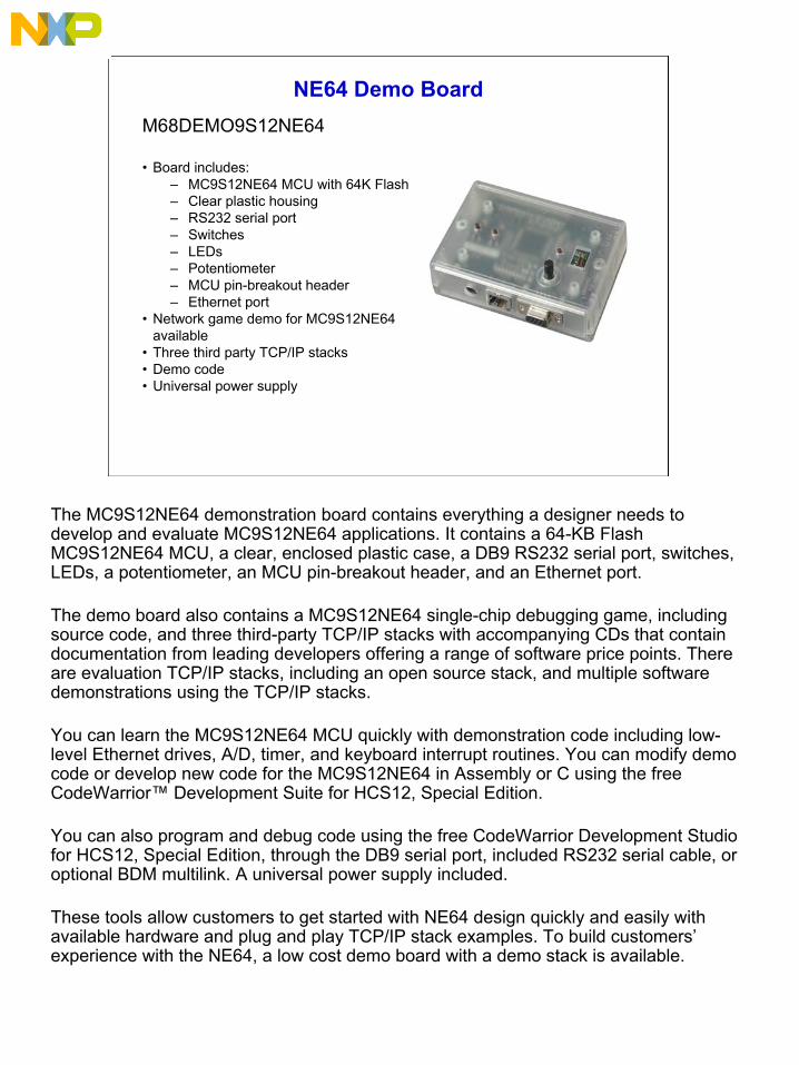
NE64 Demo BoardM68DEMO9S12NE64
• Board includes:– MC9S12NE64 MCU with 64K Flash– Clear plastic housing– RS232 serial port– Switches– LEDs– Potentiometer– MCU pin-breakout header– Ethernet port
• Network game demo for MC9S12NE64 available
• Three third party TCP/IP stacks• Demo code• Universal power supply
The MC9S12NE64 demonstration board contains everything a designer needs to develop and evaluate MC9S12NE64 applications. It contains a 64-KB Flash MC9S12NE64 MCU, a clear, enclosed plastic case, a DB9 RS232 serial port, switches, LEDs, a potentiometer, an MCU pin-breakout header, and an Ethernet port.
The demo board also contains a MC9S12NE64 single-chip debugging game, including source code, and three third-party TCP/IP stacks with accompanying CDs that contain documentation from leading developers offering a range of software price points. There are evaluation TCP/IP stacks, including an open source stack, and multiple software demonstrations using the TCP/IP stacks.
You can learn the MC9S12NE64 MCU quickly with demonstration code including low-level Ethernet drives, A/D, timer, and keyboard interrupt routines. You can modify demo code or develop new code for the MC9S12NE64 in Assembly or C using the free CodeWarrior™ Development Suite for HCS12, Special Edition.
You can also program and debug code using the free CodeWarrior Development Studio for HCS12, Special Edition, through the DB9 serial port, included RS232 serial cable, or optional BDM multilink. A universal power supply included.
These tools allow customers to get started with NE64 design quickly and easily with available hardware and plug and play TCP/IP stack examples. To build customers’ experience with the NE64, a low cost demo board with a demo stack is available.

30
NE64 Evaluation Board
M68EVB912NE64
• Board includes:– MC9S12NE64 MCU – 64K Flash– Ethernet port– IrDA port– LCD display port– Keyboard port– 512-KB SRAM– Dual DB9 RS232 serial ports– Switches– LEDs
• Breadboard area• Three third party TCP/IP stacks• Demo code• Universal power supply
The MC9S12NE64 evaluation board is sold with example stacks from three third-party vendors. The evaluation board provides access to all chip functions, while the demo board does not.
Like the MC9S12NE64 demonstration board, the MC9S12NE64 evaluation board contains everything a designer needs to develop and evaluate MC9S12NE64 applications. It contains an evaluation board with a 64-KB Flash MC9S12NE64 MCU, an Ethernet port, an Infrared Data Association (IrDA) port, an LCD display port, a keyboard port, 512-KB SRAM, dual DB9 RS232 serial ports, switches, LEDs, and a breadboard area.
The evaluation board also contains a MC9S12NE64 single-chip debugging game, including source code, and three third party TCP/IP stacks with accompanying CDs that contain documentation from leading developers offering a range of software price points. There are evaluation TCP/IP stacks, including an open source stack, and multiple software demonstrations using the TCP/IP stacks.
You can modify demo code or develop new code for the MC9S12NE64 in assembly or C using the free CodeWarrior Development Suite for HCS12, Special Edition. You can also program and debug code using the free CodeWarrior Development Studio for HC08, Special Edition, through the DB9 serial port, included RS232 serial cable, MC9S12NE64 serial monitor, or optional BDM multilink. A universal power supply included.

31
NE64 CodeWarrior
IDE: CodeWarrior for 9S12 Version 3.1
• More manuals in “chm” format (added compiler and assembler manuals)
• Support for SofTEC Microsystems PK-HCS12 series starter kits
• Changed bitfield behavior for 16-bit bit fields
• Browse information generation
• Improved Flash programming download speed for ICD12
• Updated “prm” and library files
The CodeWarrior Development Studio for HC(S)12 Release 3.1 has many improvements and enhancements. It contains emulator-like debugging support for HCS12 derivatives, including the NE64. It also has an improved stationery wizard and new visualization tools. Processor Expert also supports the NE64 Ethernet Bean.
There is support for CyclonePRO with ICD12 Target Interface from P&E Microsystems BDM cables (automated programmer and debug interface) and support for assembly INCLUDE files.

32
Integrated Solution
Development Tools
TCP Stack Software
HCS12 MCU10/100
Ethernet MAC &
PHY Controller
Complete Connectivity Integrated Ethernet
System Solution
Flash
Application Notes, Demo Kits, Evaluation Boards, and Documentation
MC9S12NE64
Freescale Semiconductor has invested heavily to develop a fully integrated Ethernet system solution. The solution is based on the HCS12 25-MHz/10-MIPS core with integrated Ethernet MAC and PHY controllers, Flash memory, peripherals, and I/O—which match application requirements. All of these factors are enhanced by the TCP/IP stack alternatives and development tools offerings.
The hardware and software features are supported by application notes, evaluation boards, demo boards, and documentation. Together, these provide the user with complete connectivity in an integrated Ethernet solution.

33
Course Summary
• Main features of the NE64• Available derivatives• Applications appropriate for the NE64• EMAC features• EPHY features• EMAC and EPHY function and capabilities related to the IEEE 802.3
standard• Development tools
In this course, you learned about the main features of the MC9S12NE64, such as the 16-bit HCS12 CPU, 64-KB Flash Memory, CRG module, 10/100 BaseT EMAC, and 10/100 BaseT EPHY. You also learned about the NE64’s available derivatives and applications. The NE64 is an exceptional solution for price-sensitive applications, real estate constrained solutions, applications where single-chip reliability is essential to achieve mean time before failure, and applications where a single-chip implementation provides for a more robust system in terms of electromagnetic compatibility due to reduced external interconnects.
You learned about the features of the EMAC and EPHY and their functionality and capabilities in the context of the IEEE 802.3 standard. The EMAC and EPHY are new peripherals for the 9S12 family. They are linked by a standard MII, so it is possible to use the on-board EMAC with an external (off-chip) PHY.
Finally, you learned about the development tools (TCP/IP stacks, demo boards, evaluation boards, and IDE) that allow users to effectively integrate the NE64 into their wired LAN applications.