COURSE HANDOUT - Rajagiri School of Engineering & Technology · PSO1: Apply the knowledge of Power...
124
COURSE HANDOUT Department of Electrical & Electronics Engineering SEMESTER 5 Period: August 2018 –November 2018
Transcript of COURSE HANDOUT - Rajagiri School of Engineering & Technology · PSO1: Apply the knowledge of Power...

COURSE HANDOUT Department of Electrical & Electronics Engineering
SEMESTER 5
Period: August 2018 –November 2018
RAJAGIRI SCHOOL OF ENGINEERING & TECHNOLOGY
DEPARTMENT OF ELECTRICAL AND ELECTRONICS ENGINEERING
Vision of the Institution:
To evolve into a premier technological and research institution, moulding eminent
professionals with creative minds, innovative ideas and sound practical skill, and to
shape a future where technology works for the enrichment of mankind.
Mission of the Institution:
To impart state-of-the-art knowledge to individuals in various technological disciplines
and to inculcate in them a high degree of social consciousness and human values,
thereby enabling them to face the challenges of life with courage and conviction.
Vision of the Department:
To excel in Electrical and Electronics Engineering education with focus on research to
make professionals with creative minds, innovative ideas and practical skills for the
betterment of mankind.
Mission of the Department:
To develop and disseminate among the individuals, the theoretical foundation, practical
aspects in the field of Electrical and Electronics Engineering and inculcate a high degree
of professional and social ethics for creating successful engineers.
Programme Educational Objectives (PEOs):
PEO 1: To provide Graduates with a solid foundation in mathematical, scientific and
engineering fundamentals and depth and breadth studies in Electrical and Electronics
engineering, so as to comprehend, analyse, design, provide solutions for practical issues
in engineering.
PEO 2: To strive for Graduates’ achievement and success in the profession or higher studies, which they may pursue.
PEO 3: To inculcate in Graduates professional and ethical attitude, effective
communication skills, teamwork skills, multidisciplinary approach, the life-long
learning needs and an ability to relate engineering issues for a successful professional
career.
Program Outcomes (POs)
Engineering Students will be able to
1. Engineering knowledge: Apply the knowledge of mathematics, science,
Engineering fundamentals, and Electrical and Electronics Engineering to the
solution of complex Engineering problems.
2. Problem analysis: Identify, formulate, review research literature, and analyze
complex Engineering problems reaching substantiated conclusions using first
principles of mathematics, natural sciences, and Engineering sciences.
3. Design/development of solutions: Design solutions for complex Engineering
problems and design system components or processes that meet the specified
needs with appropriate consideration for the public health and safety, and the
cultural, societal, and environmental considerations.
4. Conduct investigations of complex problems: Use research based knowledge
and research methods including design of experiments, analysis and
interpretation of data, and synthesis of the information to provide valid
conclusions.
5. Modern tool usage: Create, select, and apply appropriate techniques, resources,
and modern engineering and IT tools including prediction and modeling to
complex Engineering activities with an understanding of the limitations.
6. The Engineer and society: Apply reasoning informed by the contextual
knowledge to assess societal, health, safety, legal and cultural issues and the
consequent responsibilities relevant to the professional Engineering practice.

7. Environment and sustainability: Understand the impact of the professional
Engineering solutions in societal and environmental contexts, and demonstrate
the knowledge of, and the need for sustainable development.
8. Ethics: Apply ethical principles and commit to professional ethics and
responsibilities and norms of the Engineering practice.
9. Individual and team work: Function effectively as an individual, and as a
member or leader in diverse teams, and in multidisciplinary settings.
10. Communication: Communicate effectively on complex Engineering activities
with the Engineering Community and with society at large, such as, being able to
comprehend and write effective reports and design documentation, make
effective presentations, and give and receive clear instructions.
11. Project management and finance: Demonstrate knowledge and understanding
of the Engineering and management principles and apply these to one’s own work, as a member and leader in a team, to manage projects and in multi
disciplinary environments.
12. Life -long learning: Recognize the need for, and have the preparation and ability
to engage in independent and life- long learning in the broadest context of
technological change.
Programme-Specific Outcomes (PSOs)
Engineering Students will be able to:
PSO1: Apply the knowledge of Power electronics and electric drives for the analysis
design and application of innovative, dynamic and challenging industrial environment.
PSO2: Explore the technical knowledge and development of professional methodologies
in grid interconnected systems for the implementation of micro grid technology in the
area of distributed power system.
PSO3: Understand the technologies like Bio inspired algorithms in collaboration with
control system tools for the professional development and gain sufficient competence to
solve present problems in the area of intelligent machine control.

INDEX
PAGE NO.
I Assignment Schedule i
1 EE 301 Power Generation, Transmission & Protection 1
1.1 Course Information Sheet 2
1.2 Course Plan 10
1.3 Tutorials 14
1.4 Assignments 17
2 EE 303 Linear Control Systems 18
2.1 Course Information Sheet 19
2.2 Course Plan 24
2.3 Tutorials 27
2.4 Assignments 29
3 EE 305 Power Electronics 30
3.1 Course Information Sheet 31
3.2 Course Plan 36
3.3 Tutorials 39
3.4 Assignments 40
4 EE 307 Signals & Systems 41
4.1 Course Information Sheet 42
4.2 Course Plan 47
4.3 Tutorials 49
4.4 Assignments 51
5 EE 309 Microcontroller & Embedded Systems 53
5.1 Course Information Sheet 54
5.2 Course Plan 60
5.3 Tutorials 63
5.4 Assignments 66
6 EE 367 New & Renewable Sources of Energy 67
6.1 Course Information Sheet 68
6.2 Course Plan 74
6.3 Tutorials 76
6.4 Assignments 77
7 EE 369 High Voltage Engineering 78
7.1 Course Information Sheet 79
7.2 Course Plan 85
7.3 Assignments 88
8 EE 331 Digital Circuits & Embedded Systems Lab 89
8.1 Course Information Sheet 90
8.2 Course Plan 95
8.3 Lab Cycle 96
8.4 Open Questions 97
8.5 Advanced Questions 98
9 EE 333 Electrical Machines II Lab 99
9.1 Course Information Sheet 100
9.2 Course Plan 105
9.3 Lab Cycle 106
9.4 Open Questions 107
9.5 Advanced Questions 111
10 EE 341 Design Project 112
10.1 Course Information Sheet 113
10.2 Course Plan 117

Page i
ASSIGNMENT SCHEDULE
SUBJECT DATE
EE 301 Power Generation, Transmission & Protection
Week1
Week 7
EE 303 Linear Control Systems
Week 2
Week 8
EE 305 Power Electronics
Week 3
Week 9
EE 307 Signals & Systems
Week 4
Week 10
EE 309 Microcontroller & Embedded Systems
Week 5
Week 11
EE 367 New & Renewable Sources of Energy
EE 369 High Voltage Engineering
Week 6
Week 12

Course Handout
Department of Electrical & Electronics Engineering Page 1
1. EE301 POWER GENERATION, TRANMISSION &
PROTECTION

Course Handout
Department of Electrical & Electronics Engineering Page 2
1.1 COURSE INFORMATION SHEET
PROGRAMME: EEE DEGREE: B.Tech
COURSE: POWER GENERATION,
TRANSMISSION AND PROTECTION
SEMESTER: FIFTH CREDITS: 4
COURSE CODE: EE 301
REGULATION: UG
COURSE TYPE: CORE
COURSE AREA/DOMAIN: POWER
SYSTEM
CONTACT HOURS: 3+1 (Tutorial)
hours/Week.
CORRESPONDING LAB COURSE
CODE (IF ANY):
LAB COURSE NAME:
SYLLABUS:
MODULE DETAILS HOURS
I
Introduction: Typical layout of Power system Network
Generation of Electric Power:
Overview of conventional (Hydro, Thermal and Nuclear) and
Nonconventional Sources (Solar and Wind) (Block Diagram
and Brief Description Only)
Economics of Generation: Load factor, diversity factor, Load
curve (Brief description only) Numerical Problems.
Methods of power factor improvement using capacitors
9
II
Power Transmission
Transmission Line Parameters: Resistance, inductance and
capacitance of 1-Φ, 2 wire lines-composite conductors
(Derivation Required).
Inductance and capacitance of 3-Φ lines. Symmetrical and
unsymmetrical spacing-transposition-double circuit lines-bundled conductors (Derivation Required) .Numerical
Problems Modelling of Transmission Lines: Classification of lines-short lines-voltage regulation and
efficiency-medium lines-nominal T and Π configurations-ABCD constants-long lines-rigorous solution-interpretation of
long line equation-Ferranti effect. Tuned power lines-power flow through lines-Basics only
10
Course Handout
Department of Electrical & Electronics Engineering Page 3
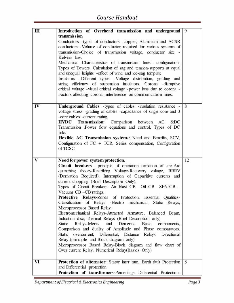
III Introduction of Overhead transmission and underground
transmission
Conductors -types of conductors -copper, Aluminium and ACSR conductors -Volume of conductor required for various systems of
transmission-Choice of transmission voltage, conductor size -Kelvin's law. Mechanical Characteristics of transmission lines –configuration-
Types of Towers. Calculation of sag and tension-supports at equal and unequal heights -effect of wind and ice-sag template
Insulators -Different types -Voltage distribution, grading and string efficiency of suspension insulators. Corona -disruptive critical voltage -visual critical voltage -power loss due to corona -
Factors affecting corona -interference on communication lines.
9
IV Underground Cables -types of cables -insulation resistance -voltage stress -grading of cables -capacitance of single core and 3
-core cables -current rating. HVDC Transmission: Comparison between AC &DC Transmission ,Power flow equations and control, Types of DC
links Flexible AC Transmission systems: Need and Benefits, SCV,
Configuration of FC + TCR, Series compensation, Configuration of TCSC
8
V Need for power system protection.
Circuit breakers –principle of operation-formation of arc-Arc quenching theory-Restriking Voltage-Recovery voltage, RRRV (Derivation Required). Interruption of Capacitive currents and
current chopping (Brief Description Only). Types of Circuit Breakers: Air blast CB –Oil CB –SF6 CB –Vacuum CB –CB ratings. Protective Relays-Zones of Protection, Essential Qualities-Classification of Relays -Electro mechanical, Static Relays,
Microprocessor Based Relay. Electromechanical Relays-Attracted Armature, Balanced Beam,
Induction disc, Thermal Relays (Brief Description only) Static Relays-Merits and Demerits, Basic components, Comparison and duality of Amplitude and Phase comparators.
Static overcurrent, Differential, Distance Relays, Directional Relay-(principle and Block diagram only)
Microprocessor Based Relay-Block diagram and flow chart of Over current Relay, Numerical Relay(Basics Only)
12
VI Protection of alternator: Stator inter turn, Earth fault Protection and Differential protection
Protection of transformers-Percentage Differential Protection-
8
Course Handout
Department of Electrical & Electronics Engineering Page 4
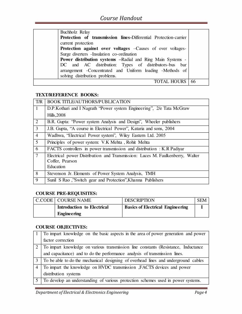
Buchholz Relay Protection of transmission lines-Differential Protection-carrier
current protection Protection against over voltages –Causes of over voltages-
Surge diverters -Insulation co-ordination Power distribution systems –Radial and Ring Main Systems -DC and AC distribution: Types of distributors-bus bar
arrangement -Concentrated and Uniform loading -Methods of solving distribution problems.
TOTAL HOURS 66
TEXT/REFERENCE BOOKS:
T/R BOOK TITLE/AUTHORS/PUBLICATION
1 D.P.Kothari and I Nagrath “Power system Engineering”, 2/e Tata McGraw
Hills,2008
2 B.R. Gupta: “Power system Analysis and Design”, Wheeler publishers
3 J.B. Gupta, “A course in Electrical Power”, Kataria and sons, 2004 4 Wadhwa, “Electrical Power system”, Wiley Eastern Ltd. 2005 5 Principles of power system: V.K Mehta , Rohit Mehta
6 FACTS controllers in power transmission and distribution : K.R Padiyar
7 Electrical power Distribution and Transmission: Luces M. Faulkenberry, Walter Coffer, Pearson
Education
8 Stevenson Jr. Elements of Power System Analysis, TMH
9 Sunil S Rao ,”Switch gear and Protection”,Khanna Publishers
COURSE PRE-REQUISITES:
C.CODE COURSE NAME DESCRIPTION SEM
Introduction to Electrical
Engineering
Basics of Electrical Engineering I
COURSE OBJECTIVES:
1 To impart knowledge on the basic aspects in the area of power generation and power
factor correction
2 To impart knowledge on various transmission line constants (Resistance, Inductance
and capacitance) and to do the performance analysis of transmission lines.
3 To be able to do the mechanical designing of overhead lines and underground cables
4 To impart the knowledge on HVDC transmission ,FACTS devices and power
distribution systems
5 To develop an understanding of various protection schemes used in power systems.
Course Handout
Department of Electrical & Electronics Engineering Page 5
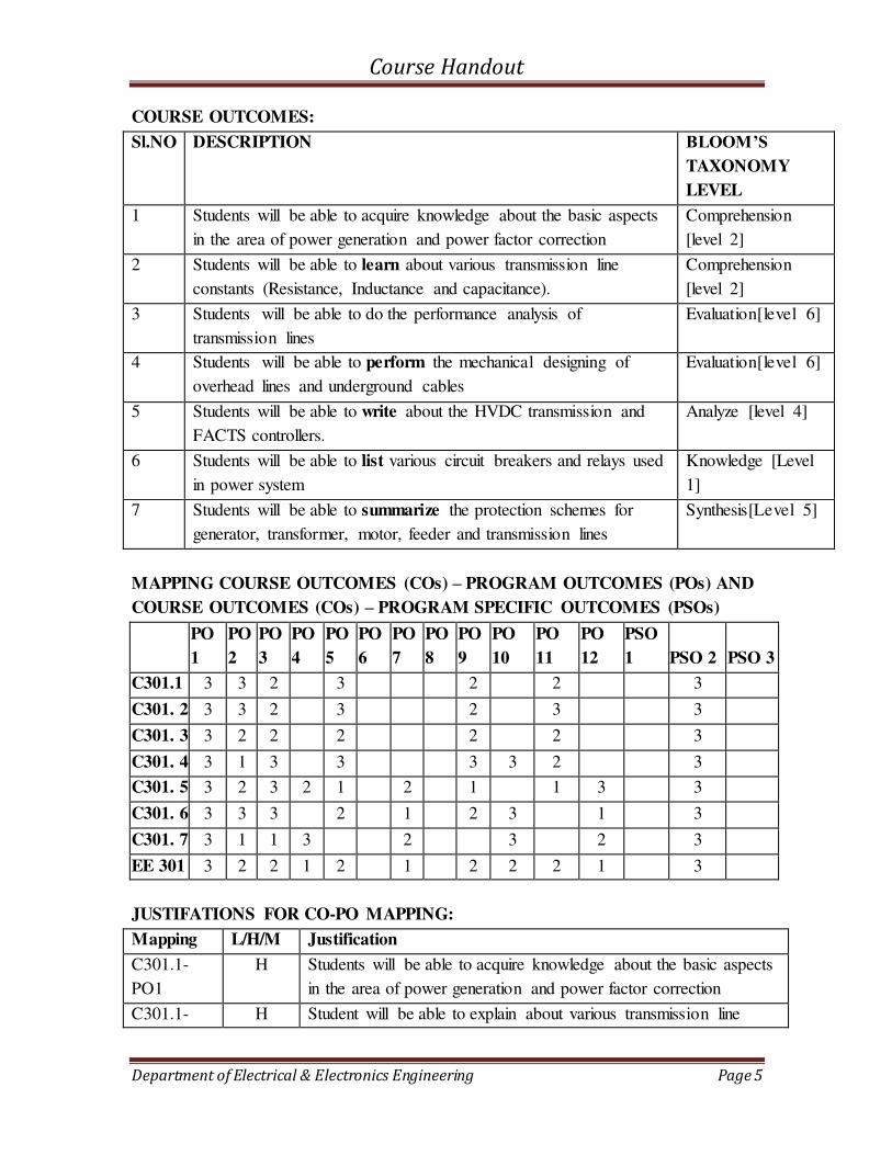
COURSE OUTCOMES:
Sl.NO DESCRIPTION BLOOM’S TAXONOMY
LEVEL
1 Students will be able to acquire knowledge about the basic aspects
in the area of power generation and power factor correction
Comprehension
[level 2]
2 Students will be able to learn about various transmission line
constants (Resistance, Inductance and capacitance).
Comprehension
[level 2]
3 Students will be able to do the performance analysis of
transmission lines
Evaluation[level 6]
4 Students will be able to perform the mechanical designing of
overhead lines and underground cables
Evaluation[level 6]
5 Students will be able to write about the HVDC transmission and
FACTS controllers.
Analyze [level 4]
6 Students will be able to list various circuit breakers and relays used
in power system
Knowledge [Level
1]
7 Students will be able to summarize the protection schemes for
generator, transformer, motor, feeder and transmission lines
Synthesis[Level 5]
MAPPING COURSE OUTCOMES (COs) – PROGRAM OUTCOMES (POs) AND
COURSE OUTCOMES (COs) – PROGRAM SPECIFIC OUTCOMES (PSOs)
PO
1
PO
2
PO
3
PO
4
PO
5
PO
6
PO
7
PO
8
PO
9
PO
10
PO
11
PO
12
PSO
1 PSO 2 PSO 3
C301.1 3 3 2 3 2 2 3
C301. 2 3 3 2 3 2 3 3
C301. 3 3 2 2 2 2 2 3
C301. 4 3 1 3 3 3 3 2 3
C301. 5 3 2 3 2 1 2 1 1 3 3
C301. 6 3 3 3 2 1 2 3 1 3
C301. 7 3 1 1 3 2 3 2 3
EE 301 3 2 2 1 2 1 2 2 2 1 3
JUSTIFATIONS FOR CO-PO MAPPING:
Mapping L/H/M Justification
C301.1-
PO1
H Students will be able to acquire knowledge about the basic aspects
in the area of power generation and power factor correction
C301.1- H Student will be able to explain about various transmission line
Course Handout
Department of Electrical & Electronics Engineering Page 6
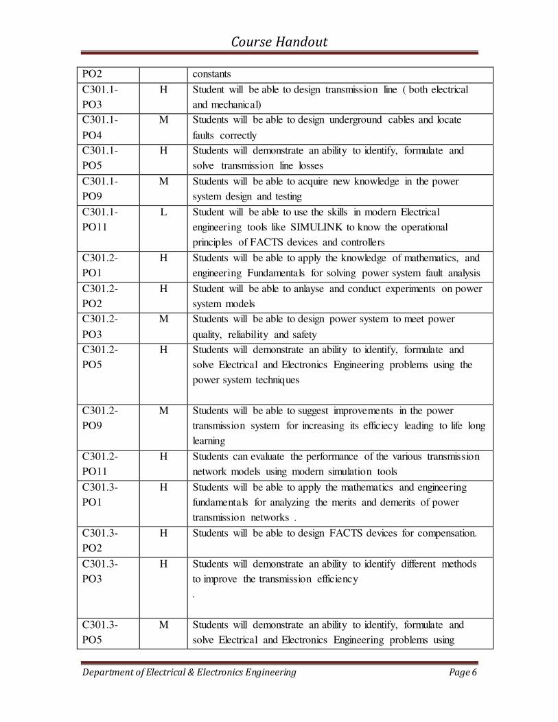
PO2 constants
C301.1-
PO3
H Student will be able to design transmission line ( both electrical
and mechanical)
C301.1-
PO4
M Students will be able to design underground cables and locate
faults correctly
C301.1-
PO5
H Students will demonstrate an ability to identify, formulate and
solve transmission line losses
C301.1-
PO9
M Students will be able to acquire new knowledge in the power
system design and testing
C301.1-
PO11
L Student will be able to use the skills in modern Electrical
engineering tools like SIMULINK to know the operational
principles of FACTS devices and controllers
C301.2-
PO1
H Students will be able to apply the knowledge of mathematics, and
engineering Fundamentals for solving power system fault analysis
C301.2-
PO2
H Student will be able to anlayse and conduct experiments on power
system models
C301.2-
PO3
M Students will be able to design power system to meet power
quality, reliability and safety
C301.2-
PO5
H Students will demonstrate an ability to identify, formulate and
solve Electrical and Electronics Engineering problems using the
power system techniques
C301.2-
PO9
M Students will be able to suggest improvements in the power
transmission system for increasing its efficiecy leading to life long
learning
C301.2-
PO11
H Students can evaluate the performance of the various transmission
network models using modern simulation tools
C301.3-
PO1
H Students will be able to apply the mathematics and engineering
fundamentals for analyzing the merits and demerits of power
transmission networks .
C301.3-
PO2
H Students will be able to design FACTS devices for compensation.
C301.3-
PO3
H Students will demonstrate an ability to identify different methods
to improve the transmission efficiency
.
C301.3-
PO5
M Students will demonstrate an ability to identify, formulate and
solve Electrical and Electronics Engineering problems using
Course Handout
Department of Electrical & Electronics Engineering Page 7
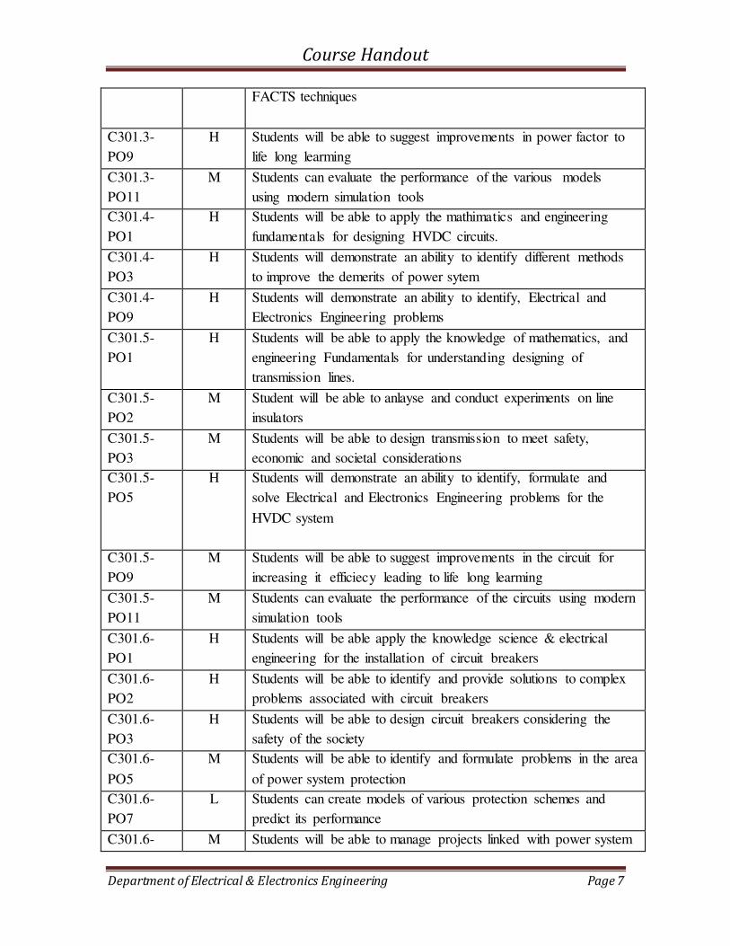
FACTS techniques
C301.3-
PO9
H Students will be able to suggest improvements in power factor to
life long learming
C301.3-
PO11
M Students can evaluate the performance of the various models
using modern simulation tools
C301.4-
PO1
H Students will be able to apply the mathimatics and engineering
fundamentals for designing HVDC circuits.
C301.4-
PO3
H Students will demonstrate an ability to identify different methods
to improve the demerits of power sytem
C301.4-
PO9
H Students will demonstrate an ability to identify, Electrical and
Electronics Engineering problems
C301.5-
PO1
H Students will be able to apply the knowledge of mathematics, and
engineering Fundamentals for understanding designing of
transmission lines.
C301.5-
PO2
M Student will be able to anlayse and conduct experiments on line
insulators
C301.5-
PO3
M Students will be able to design transmission to meet safety,
economic and societal considerations
C301.5-
PO5
H Students will demonstrate an ability to identify, formulate and
solve Electrical and Electronics Engineering problems for the
HVDC system
C301.5-
PO9
M Students will be able to suggest improvements in the circuit for
increasing it efficiecy leading to life long learming
C301.5-
PO11
M Students can evaluate the performance of the circuits using modern
simulation tools
C301.6-
PO1
H Students will be able apply the knowledge science & electrical
engineering for the installation of circuit breakers
C301.6-
PO2
H Students will be able to identify and provide solutions to complex
problems associated with circuit breakers
C301.6-
PO3
H Students will be able to design circuit breakers considering the
safety of the society
C301.6-
PO5
M Students will be able to identify and formulate problems in the area
of power system protection
C301.6-
PO7
L Students can create models of various protection schemes and
predict its performance
C301.6- M Students will be able to manage projects linked with power system
Course Handout
Department of Electrical & Electronics Engineering Page 8
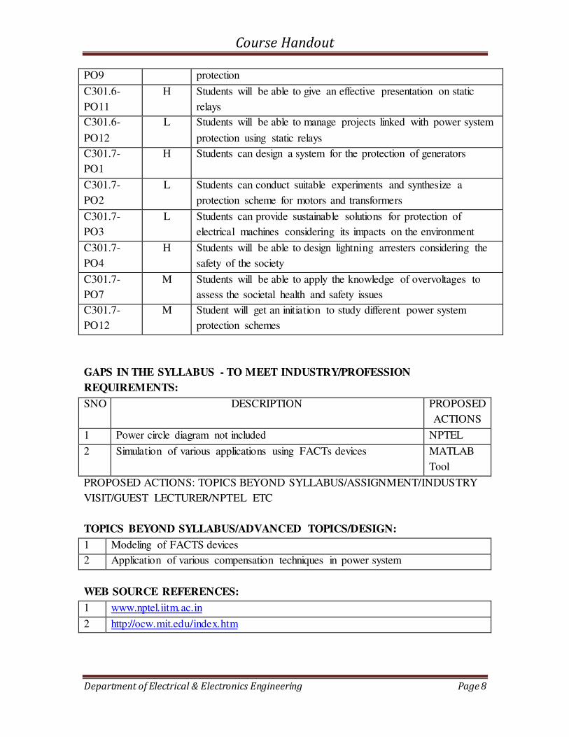
PO9 protection
C301.6-
PO11
H Students will be able to give an effective presentation on static
relays
C301.6-
PO12
L Students will be able to manage projects linked with power system
protection using static relays
C301.7-
PO1
H Students can design a system for the protection of generators
C301.7-
PO2
L Students can conduct suitable experiments and synthesize a
protection scheme for motors and transformers
C301.7-
PO3
L Students can provide sustainable solutions for protection of
electrical machines considering its impacts on the environment
C301.7-
PO4
H Students will be able to design lightning arresters considering the
safety of the society
C301.7-
PO7
M Students will be able to apply the knowledge of overvoltages to
assess the societal health and safety issues
C301.7-
PO12
M Student will get an initiation to study different power system
protection schemes
GAPS IN THE SYLLABUS - TO MEET INDUSTRY/PROFESSION
REQUIREMENTS:
SNO DESCRIPTION PROPOSED
ACTIONS
1 Power circle diagram not included NPTEL
2 Simulation of various applications using FACTs devices MATLAB
Tool
PROPOSED ACTIONS: TOPICS BEYOND SYLLABUS/ASSIGNMENT/INDUSTRY
VISIT/GUEST LECTURER/NPTEL ETC
TOPICS BEYOND SYLLABUS/ADVANCED TOPICS/DESIGN:
1 Modeling of FACTS devices
2 Application of various compensation techniques in power system
WEB SOURCE REFERENCES:
1 www.nptel.iitm.ac.in
2 http://ocw.mit.edu/index.htm

Course Handout
Department of Electrical & Electronics Engineering Page 9
DELIVERY/INSTRUCTIONAL METHODOLOGIES:
☐CHALK &
TALK
☐ STUD.
ASSIGNMENT
☐WEB
RESOURCES
☐ LCD/SMART
BOARDS
☐STUD.
SEMINARS
☐ ADD-ON
COURSES
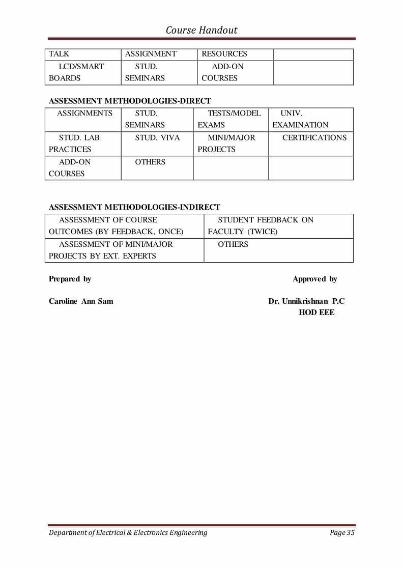
ASSESSMENT METHODOLOGIES-DIRECT
☐ASSIGNMENTS ☐ STUD.
SEMINARS
☐TESTS/MODEL
EXAMS
☐UNIV.
EXAMINATION
☐ STUD. LAB
PRACTICES
. STUD. VIVA ☐ MINI/MAJOR
PROJECTS
☐
CERTIFICATIONS
☐ ADD-ON
COURSES
☐ OTHERS
ASSESSMENT METHODOLOGIES-INDIRECT
ASSESSMENT OF COURSE
OUTCOMES (BY FEEDBACK, ONCE)
☐STUDENT FEEDBACK ON
FACULTY (TWICE)
☐ ASSESSMENT OF MINI/MAJOR
PROJECTS BY EXT. EXPERTS
☐ OTHERS
Prepared by Approved by
PRATHIBHA P.K. Dr.P.C. Unnikrishnan
(HOD)

Course Handout
Department of Electrical & Electronics Engineering Page 10
1.2 COURSE PLAN
Sl.No Module Planned
Date
Planned
1 1 Lecture 1 Introduction to electrical power generation, transmission and
protection
2 1 Lecture 2 Introduction to electrical power generation, transmission and
protection
3 1 Lecture 3 Overview of Hydro and Thermal power plant with block
diagram
4 1 Lecture 4 Overview of Nuclear power plant
5 1 Lecture 5 Solar and Wind- Non- conventional sources
6 1 Lecture 6 Maximum Demand -Demand Factor, Diversity Factor and
load factor
7 1 Lecture 7 Load Curve and numerical problems
8 1 Lecture 8 Methods of power factor improvement using capacitors
9 2 Lecture 9 Introduction class of Constants of transmission line
10 2 Lecture 10 Resistance, Skin effect and Proximity effect
11 2 Lecture 11 Flux linkages due to internal flux,Flux linkages due to
external flux
12 2 Lecture 12 Flux linkages in a group of parallel current carrying
conductors Inductance of a single phase two wire line -
Derivation
13 2 Lecture 13 Inductance of three phase overhead line- Symmetrical spacing
14 2 Lecture 14 Inductance of a three phase overhead line- Unsymmetrical
spacing, Transposition Concept of Self and Mutual GMD
15 2 Lecture 15 solving Problems of Symmetrical and unsymmetrical spacing

Course Handout
Department of Electrical & Electronics Engineering Page 11
16 2 Lecture 16 Capacitance, potential at a charged single conductor Potential
at a conductor in a group of conductors
18 2 Lecture 17 Capacitance of a single phase two wire line Capacitance of a
three phase line with symmetrical and unsymmetrical spacing
19 2 Lecture 18 Tutorials on Capacitance of line with symmetrical and
unsymmetrical spacing
20 2 Lecture 19 Introduction-Classification of transmission line
21 2 Lecture 20 Analysis of single phase and three phase short line
22 2 Lecture 21 Medium lines- Nominal T and Pi method Solving problems of
short and medium lines
23 2 Lecture 22 Rigorous solution of long transmission line - interpretation of
long line equation ABCD constants of TL
24 2 Lecture 23 Ferranti effect-tuned power lines-power flow through lines
25 3 Lecture 24 Conductors -types of conductors -Volume of conductor
required for various systems of transmission
26 3 Lecture 25 Choice of transmission voltage, conductor size -Kelvin's law
27 3 Lecture 26 Mechanical Characteristics of transmission lines –
configuration-Types of Towers.
28 3 Lecture 27 Calculation of sag and tension- supports at equal and unequal
heights -effect of wind and ice- sag template
29 3 Lecture 28 Insulators -Different types -Voltage distribution, grading and
string efficiency of suspension insulators
30 3 Lecture 29 Corona -disruptive critical voltage -visual critical voltage -
power loss due to corona -Factors affecting corona -
interference on communication lines.
31 3 Lecture 30 Underground Cables -types of cables -insulation resistance -
voltage stress -grading of cables
32 3 Lecture 31 Capacitance of single core and 3 -core cables -current rating.
Course Handout
Department of Electrical & Electronics Engineering Page 12
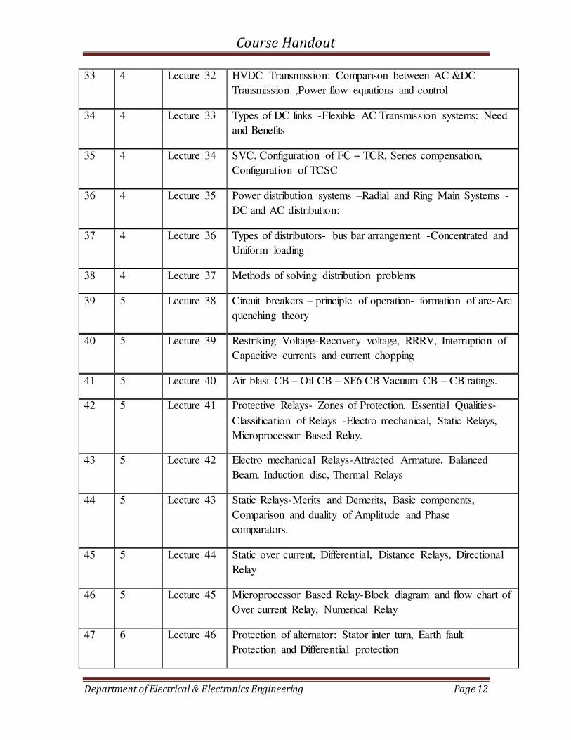
33 4 Lecture 32 HVDC Transmission: Comparison between AC &DC
Transmission ,Power flow equations and control
34 4 Lecture 33 Types of DC links -Flexible AC Transmission systems: Need
and Benefits
35 4 Lecture 34 SVC, Configuration of FC + TCR, Series compensation,
Configuration of TCSC
36 4 Lecture 35 Power distribution systems –Radial and Ring Main Systems -
DC and AC distribution:
37 4 Lecture 36 Types of distributors- bus bar arrangement -Concentrated and
Uniform loading
38 4 Lecture 37 Methods of solving distribution problems
39 5 Lecture 38 Circuit breakers – principle of operation- formation of arc-Arc
quenching theory
40 5 Lecture 39 Restriking Voltage-Recovery voltage, RRRV, Interruption of
Capacitive currents and current chopping
41 5 Lecture 40 Air blast CB – Oil CB – SF6 CB Vacuum CB – CB ratings.
42 5 Lecture 41 Protective Relays- Zones of Protection, Essential Qualities-
Classification of Relays -Electro mechanical, Static Relays,
Microprocessor Based Relay.
43 5 Lecture 42 Electro mechanical Relays-Attracted Armature, Balanced
Beam, Induction disc, Thermal Relays
44 5 Lecture 43 Static Relays-Merits and Demerits, Basic components,
Comparison and duality of Amplitude and Phase
comparators.
45 5 Lecture 44 Static over current, Differential, Distance Relays, Directional
Relay
46 5 Lecture 45 Microprocessor Based Relay-Block diagram and flow chart of
Over current Relay, Numerical Relay
47 6 Lecture 46 Protection of alternator: Stator inter turn, Earth fault
Protection and Differential protection
Course Handout
Department of Electrical & Electronics Engineering Page 13
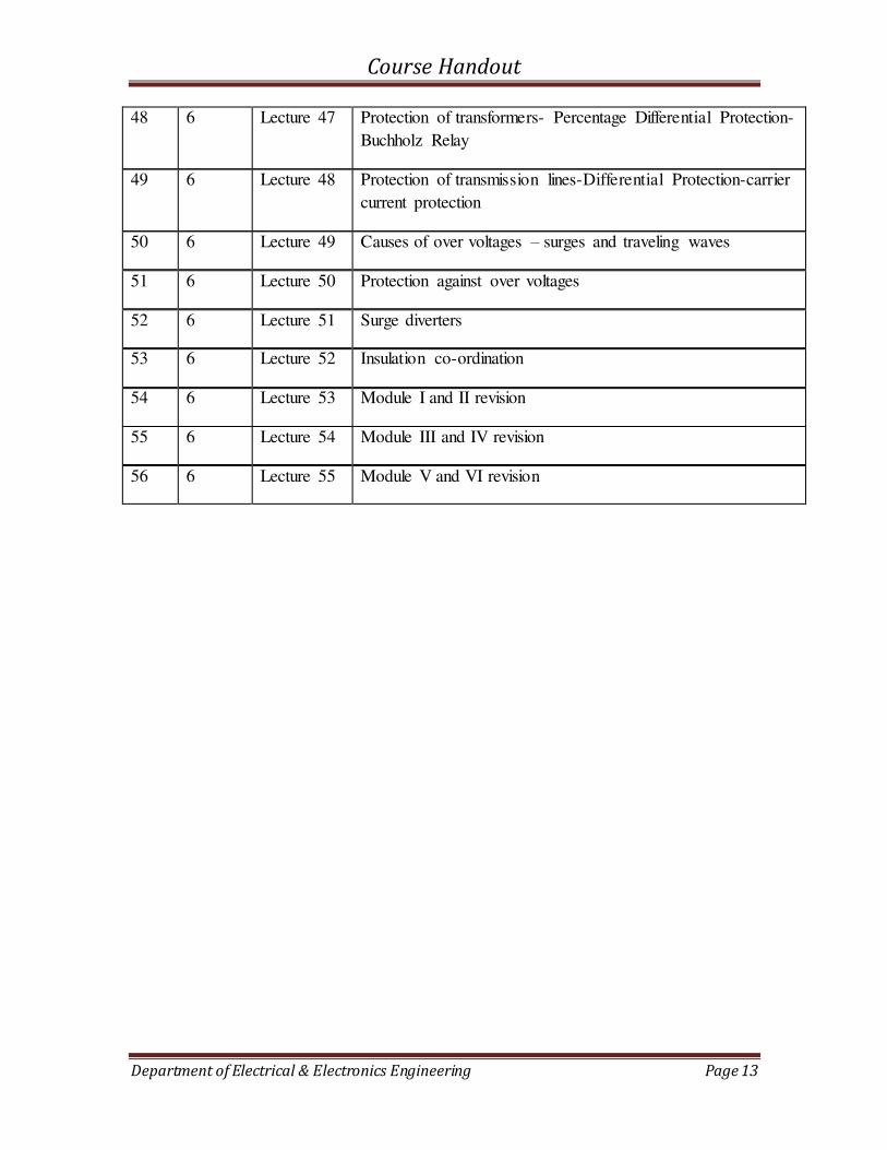
48 6 Lecture 47 Protection of transformers- Percentage Differential Protection-
Buchholz Relay
49 6 Lecture 48 Protection of transmission lines-Differential Protection-carrier
current protection
50 6 Lecture 49 Causes of over voltages – surges and traveling waves
51 6 Lecture 50 Protection against over voltages
52 6 Lecture 51 Surge diverters
53 6 Lecture 52 Insulation co-ordination
54 6 Lecture 53 Module I and II revision
55 6 Lecture 54 Module III and IV revision
56 6 Lecture 55 Module V and VI revision
Course Handout
Department of Electrical & Electronics Engineering Page 14
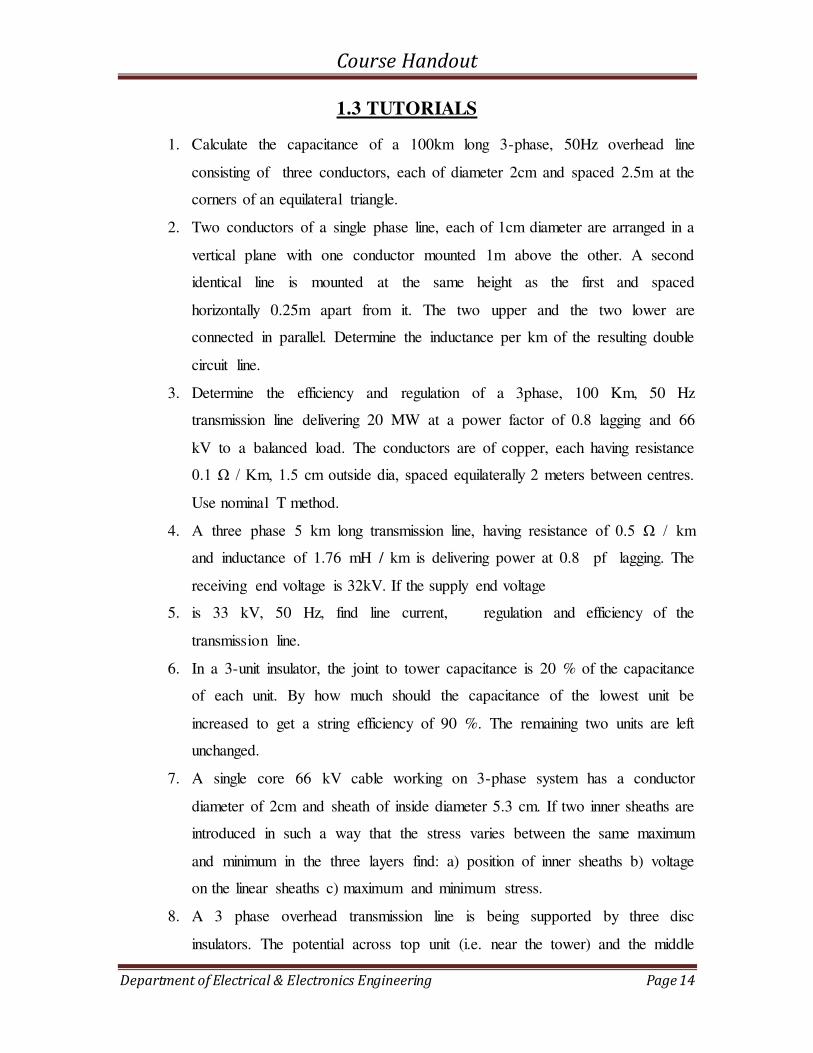
1.3 TUTORIALS
1. Calculate the capacitance of a 100km long 3-phase, 50Hz overhead line
consisting of three conductors, each of diameter 2cm and spaced 2.5m at the
corners of an equilateral triangle.
2. Two conductors of a single phase line, each of 1cm diameter are arranged in a
vertical plane with one conductor mounted 1m above the other. A second
identical line is mounted at the same height as the first and spaced
horizontally 0.25m apart from it. The two upper and the two lower are
connected in parallel. Determine the inductance per km of the resulting double
circuit line.
3. Determine the efficiency and regulation of a 3phase, 100 Km, 50 Hz
transmission line delivering 20 MW at a power factor of 0.8 lagging and 66
kV to a balanced load. The conductors are of copper, each having resistance
0.1 Ω / Km, 1.5 cm outside dia, spaced equilaterally 2 meters between centres.
Use nominal T method.
4. A three phase 5 km long transmission line, having resistance of 0.5 Ω / km
and inductance of 1.76 mH / km is delivering power at 0.8 pf lagging. The
receiving end voltage is 32kV. If the supply end voltage
5. is 33 kV, 50 Hz, find line current, regulation and efficiency of the
transmission line.
6. In a 3-unit insulator, the joint to tower capacitance is 20 % of the capacitance
of each unit. By how much should the capacitance of the lowest unit be
increased to get a string efficiency of 90 %. The remaining two units are left
unchanged.
7. A single core 66 kV cable working on 3-phase system has a conductor
diameter of 2cm and sheath of inside diameter 5.3 cm. If two inner sheaths are
introduced in such a way that the stress varies between the same maximum
and minimum in the three layers find: a) position of inner sheaths b) voltage
on the linear sheaths c) maximum and minimum stress.
8. A 3 phase overhead transmission line is being supported by three disc
insulators. The potential across top unit (i.e. near the tower) and the middle

Course Handout
Department of Electrical & Electronics Engineering Page 15
unit are 8 kV and 11 kV respectively. Calculate, a) The ratio of capacitance
between pin and earth to the self capacitance of each unit b) Line Voltage c)
String Efficiency
9. A conductor of 1cm diameter passes centrally through porcelain cylinder of
internal diameter 2 cms and external diameter 7cms. The cylinder is
surrounded by a tightly fitting metal sheath. The permittivity of porcelain is 5
and the peak voltage gradient in air must not exceed 34 kV / cm. Determine
the maximum safe working voltage.
10. Calculate the most economical diameter of a single core cable to be used on
132 kV, 3 phase system. Find also the overall diameter of the insulation, if the
peak permissible stress does not exceed 60 kV / cm. also derive the formula
used here.
11. A string of 4 insulator units has a self capacitance equal to 4 times the pin to
earth capacitance. Calculate a) Voltage distribution as a % of total voltage b)
String efficiency
12. With a neat diagram, explain the strain and stay insulators. A cable is graded
with three dielectrics of permittivity 4, 3 and 2. The maximum permissible
potential gradient for all dielectrics is same and equal to 30 kV/cm. The core
diameter is 1.5cm and sheath diameter is 5.5 cm. Determine the working
voltage.
13. The towers of height 30m and 90m respectively support a transmission line
conductor at water crossing. The horizontal distance between the towers is
500m. If the tension in the conductor is 1600kg, find the minimum clearance
of the conductor and water and clearance mid-way between the supports.
Weight of conductor is 1.5 kg/m. Bases of the towers can be considered to be
at water level.
14. An overhead line has a span of 336m. The line is supported at a water crossing
from two towers whose heights are 33.6m and 29m above water level. The
weight of conductor is 8.33N/m and tension in the conductor is not to exceed
3.34*104N.Find 1) Clearance between lowest point on conductor and water 2)
Horizontal distance of this point from lower support.
Course Handout
Department of Electrical & Electronics Engineering Page 16
15. A three phase, 220kV, 50 Hz transmission line consists of 1.5cm radius
conductor spaced 2 meters apart in equilateral triangular formation. If the
temperature is 400C and atmospheric pressure is 76cm, calculate the corona
loss per km of the line. Take mo= 0.85

Course Handout
Department of Electrical & Electronics Engineering Page 17
1.4 ASSIGNMENTS
ASSIGNMENT 1
1. Derive the inductance of composite and bundled conductors.
2. Derive the capacitance of composite and bundled conductors.
Submission date : 3rd September 2018
ASSIGNMENT 2
1. Derive the dielectric stress and insulation resistance of single core cable.
2. Derive the capacitance of single core and three core cable
Submission date : 29th October 2018
Course Handout
Department of Electrical & Electronics Engineering Page 18
2. EE303 LINEAR CONTROL SYSTEMS

Course Handout
Department of Electrical & Electronics Engineering Page 19
2.1 COURSE INFORMATION SHEET
PROGRAMME: EEE DEGREE: BTECH
COURSE: Linear Control Systems SEMESTER: 5 CREDITS:3
COURSE CODE: EE 303 REGULATION:
UG
COURSE TYPE: Core
COURSE AREA/DOMAIN: Control Systems CONTACT HOURS: 2+1 (Tutorial)
hours/Week.
CORRESPONDING LAB COURSE CODE (IF
ANY): No
LAB COURSE NAME: Nil
SYLLABUS:
Module Contents Hour
s
Sem. Exam
Marks
I
Open loop-and closed loop control systems: Transfer function of LTI systems-Mechanical and Electromechanical systems – Force voltage
and force current analogy - block diagram representation - block diagram reduction - signal flow graph - Mason's gain formula -
characteristic equation.
8 15%
II
Control system components: DC and AC servo motors – synchro - gyroscope - stepper motor - Tacho generator. Time domain analysis of control systems: Transient and steady state
responses - time domain specifications - first and second order systems - step responses of first and second order systems.
6 15%
FIRST INTERNAL EXAMINATION
III
Error analysis - steady state error analysis - static error coefficient of
type 0,1, 2 systems - Dynamic error coefficients. Concept of stability: Time response for various pole locations - stability of feedback system - Routh's stability criterion
7 15%
IV Root locus - General rules for constructing Root loci – stability from root loci - effect of addition of poles and zeros.
7 15%
SECOND INTERNAL EXAMINATION
V Frequency domain analysis: Frequency domain specifications- Analysis based on Bode plot - Log magnitude vs. phase plot,
7 20%
VI Polar plot- Nyquist stability criterion-Nichols chart - Non-minimum phase system - transportation lag.
7 20%
Course Handout
Department of Electrical & Electronics Engineering Page 20
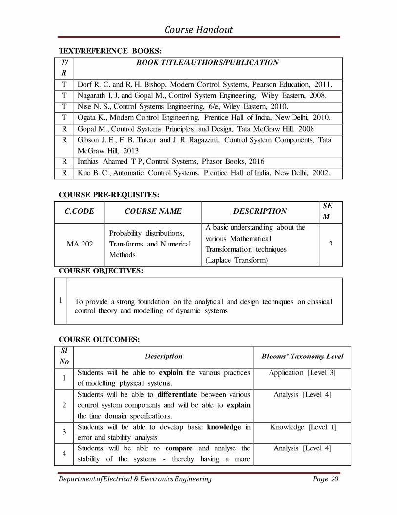
TEXT/REFERENCE BOOKS:
T/
R
BOOK TITLE/AUTHORS/PUBLICATION
T Dorf R. C. and R. H. Bishop, Modern Control Systems, Pearson Education, 2011.
T Nagarath I. J. and Gopal M., Control System Engineering, Wiley Eastern, 2008.
T Nise N. S., Control Systems Engineering, 6/e, Wiley Eastern, 2010.
T Ogata K., Modern Control Engineering, Prentice Hall of India, New Delhi, 2010.
R Gopal M., Control Systems Principles and Design, Tata McGraw Hill, 2008
R Gibson J. E., F. B. Tuteur and J. R. Ragazzini, Control System Components, Tata
McGraw Hill, 2013
R Imthias Ahamed T P, Control Systems, Phasor Books, 2016
R Kuo B. C., Automatic Control Systems, Prentice Hall of India, New Delhi, 2002.
COURSE PRE-REQUISITES:
C.CODE COURSE NAME DESCRIPTION SE
M
MA 202
Probability distributions,
Transforms and Numerical
Methods
A basic understanding about the
various Mathematical
Transformation techniques
(Laplace Transform)
3
COURSE OBJECTIVES:
1
To provide a strong foundation on the analytical and design techniques on classical control theory and modelling of dynamic systems
COURSE OUTCOMES:
Sl
No Description Blooms’ Taxonomy Level
1 Students will be able to explain the various practices
of modelling physical systems.
Application [Level 3]
2
Students will be able to differentiate between various
control system components and will be able to explain
the time domain specifications.
Analysis [Level 4]
3 Students will be able to develop basic knowledge in
error and stability analysis
Knowledge [Level 1]
4 Students will be able to compare and analyse the
stability of the systems - thereby having a more
Analysis [Level 4]

Course Handout
Department of Electrical & Electronics Engineering Page 21
realistic approach towards the design of Control
systems
5
Students will be able to classify and understand the
various frequency domain analysis technique in
control systems.
Comprehension [Level 2]
MAPPING COURSE OUTCOMES (COs) – PROGRAM OUTCOMES (POs) AND
COURSE OUTCOMES (COs) – PROGRAM SPECIFIC OUTCOMES (PSOs):
PO
1
PO
2
PO
3
PO
4
PO
5
PO
6
PO
7
PO
8
PO
9
PO
10
PO
11
PO
12
PSO 1 PSO 2 PSO 3
C303.1 1 3 2 2 2 1 3
C303.2 1 2 2 2
C303.3 2 1 2 3 2 3
C303.4 2 3 2 2 2
C303.5 3 2 1 3
EE
303 1 2 2 2 2 2 2 1 2 2 3
JUSTIFATIONS FOR CO-PO MAPPING:
Mapping L/H/M Justification
C303.1-PO1 L Students will be able to explain the fundamentals of control system
classifications.
C303.1-PO3 H Students will be able to develop models of physical systems to
meet specific needs of society.
C303.1-PO5 M Students will be able to use modern tools to model control systems
to better understand its usage and limitations.
C303.1-PO7 M Students will be able to understand the importance of control
systems for sustainable development.
C303.1-P10 M
Students will be able to communicate effectively on complex
control system strategies after its design using presentations with
public.
C303.2-PO3 L Students will be able to design systems, using various control
system components as actuators to meet the needs of the end user
C303.2-PO4 M Students will be able to analyze and interpret control signal data in
Course Handout
Department of Electrical & Electronics Engineering Page 22
time domain.
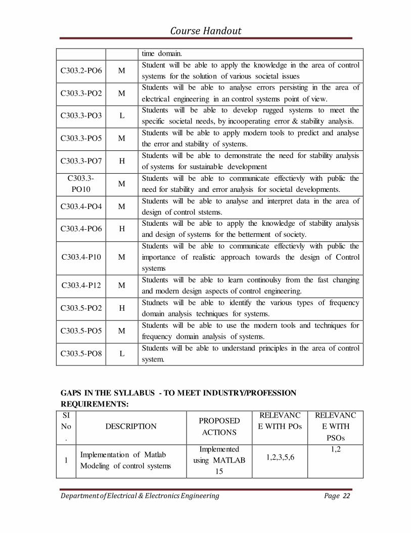
C303.2-PO6 M Student will be able to apply the knowledge in the area of control
systems for the solution of various societal issues
C303.3-PO2 M Students will be able to analyse errors persisting in the area of
electrical engineering in an control systems point of view.
C303.3-PO3 L Students will be able to develop rugged systems to meet the
specific societal needs, by incooperating error & stability analysis.
C303.3-PO5 M Students will be able to apply modern tools to predict and analyse
the error and stability of systems.
C303.3-PO7 H Students will be able to demonstrate the need for stability analysis
of systems for sustainable development
C303.3-
PO10 M
Students will be able to communicate effectievly with public the
need for stability and error analysis for societal developments.
C303.4-PO4 M Students will be able to analyse and interpret data in the area of
design of control ststems.
C303.4-PO6 H Students will be able to apply the knowledge of stability analysis
and design of systems for the betterment of society.
C303.4-P10 M
Students will be able to communicate effectievly with public the
importance of realistic approach towards the design of Control
systems
C303.4-P12 M Students will be able to learn continoulsy from the fast changing
and modern design aspects of control engineering.
C303.5-PO2 H Studnets will be able to identify the various types of frequency
domain analysis techniques for systems.
C303.5-PO5 M Students will be able to use the modern tools and techniques for
frequency domain analysis of systems.
C303.5-PO8 L Students will be able to understand principles in the area of control
system.
GAPS IN THE SYLLABUS - TO MEET INDUSTRY/PROFESSION
REQUIREMENTS:
SI
No
.
DESCRIPTION PROPOSED
ACTIONS
RELEVANC
E WITH POs
RELEVANC
E WITH
PSOs
1 Implementation of Matlab
Modeling of control systems
Implemented
using MATLAB
15
1,2,3,5,6 1,2

Course Handout
Department of Electrical & Electronics Engineering Page 23
PROPOSED ACTIONS: TOPICS BEYOND SYLLABUS/ASSIGNMENT/INDUSTRY
VISIT/GUEST LECTURER/NPTEL ETC
TOPICS BEYOND SYLLABUS/ADVANCED TOPICS/DESIGN:
SI
No
.
DESCRIPTION PROPOSED
ACTIONS
RELEVANC
E WITH POs
RELEVANC
E WITH
PSOs
1 Introduction to Matlab
Modeling Additional Class 1,2,3,5,6
1, 2
WEB SOURCE REFERENCES:
1 (2018) Matlab Website [Online] Available: http://www.matlab.com
DELIVERY/INSTRUCTIONAL METHODOLOGIES:
CHALK & TALK STUD.
ASSIGNMENT
WEB
RESOURCES
LCD/SMART
BOARDS
STUD.
SEMINARS
ADD-ON
COURSES
ASSESSMENT METHODOLOGIES-DIRECT
ASSIGNMENTS STUD.
SEMINARS
TESTS/MODEL
EXAMS
UNIV.
EXAMINATION
STUD. LAB
PRACTICES
STUD. VIVA MINI/MAJOR
PROJECTS
CERTIFICATIONS
ADD-ON
COURSES
OTHERS
ASSESSMENT METHODOLOGIES-INDIRECT
ASSESSMENT OF COURSE
OUTCOMES (BY FEEDBACK, ONCE)
STUDENT FEEDBACK ON
FACULTY (TWICE)
ASSESSMENT OF MINI/MAJOR
PROJECTS BY EXT. EXPERTS
OTHERS
Prepared by Approved by
Dr Elizabeth Rita Samuel Dr P. C. Unnikrishnan
(HOD)
Course Handout
Department of Electrical & Electronics Engineering Page 24
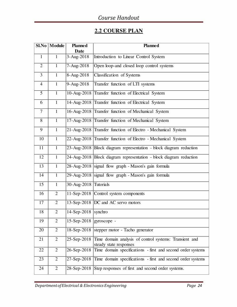
2.2 COURSE PLAN
Sl.No Module Planned
Date
Planned
1 1 3-Aug-2018 Introduction to Linear Control System
2 1 7-Aug-2018 Open loop-and closed loop control systems
3 1 8-Aug-2018 Classification of Systems
4 1 9-Aug-2018 Transfer function of LTI systems
5 1 10-Aug-2018 Transfer function of Electrical System
6 1 14-Aug-2018 Transfer function of Electrical System
7 1 16-Aug-2018 Transfer function of Mechanical System
8 1 17-Aug-2018 Transfer function of Mechanical System
9 1 21-Aug-2018 Transfer function of Electro - Mechanical System
10 1 22-Aug-2018 Transfer function of Electro - Mechanical System
11 1 23-Aug-2018 Block diagram representation - block diagram reduction
12 1 24-Aug-2018 Block diagram representation - block diagram reduction
13 1 28-Aug-2018 signal flow graph - Mason's gain formula
14 1 29-Aug-2018 signal flow graph - Mason's gain formula
15 1 30-Aug-2018 Tutorials
16 2 11-Sep-2018 Control system components
17 2 13-Sep-2018 DC and AC servo motors
18 2 14-Sep-2018 synchro
19 2 15-Sep-2018 gyroscope -
20 2 18-Sep-2018 stepper motor - Tacho generator
21 2 25-Sep-2018 Time domain analysis of control systems: Transient and steady state responses
22 2 26-Sep-2018 Time domain specifications - first and second order systems
23 2 27-Sep-2018 Time domain specifications - first and second order systems
24 2 28-Sep-2018 Step responses of first and second order systems.
Course Handout
Department of Electrical & Electronics Engineering Page 25
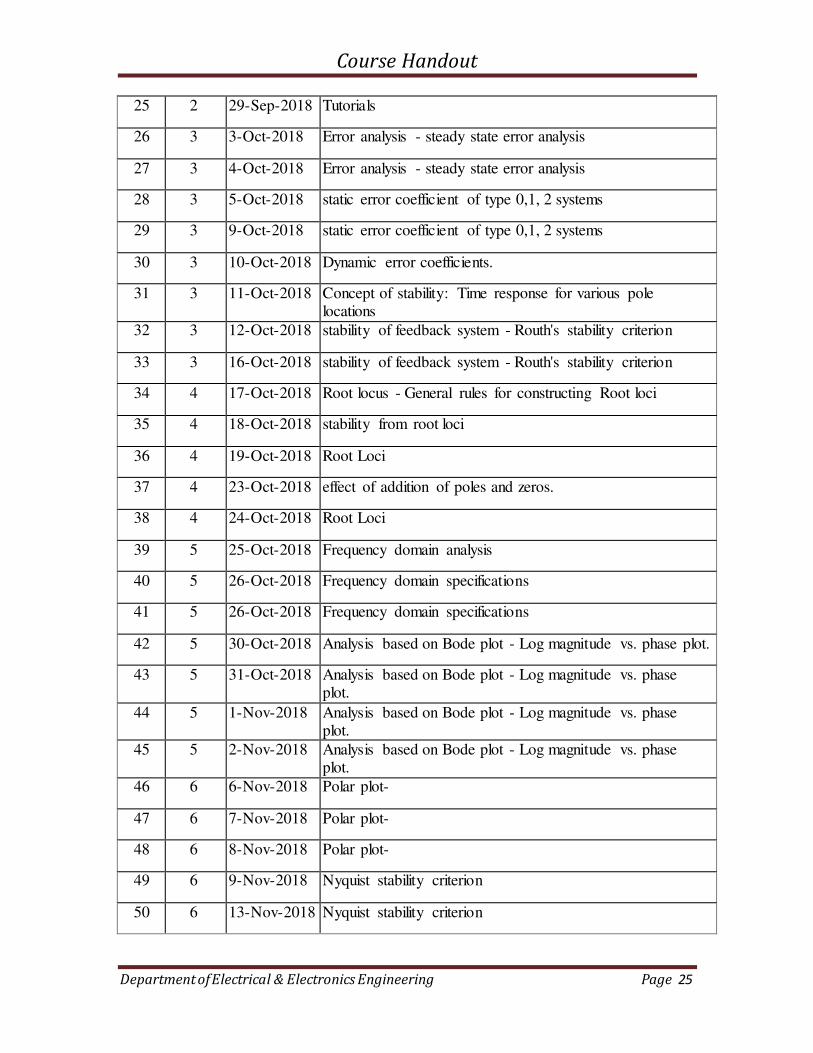
25 2 29-Sep-2018 Tutorials
26 3 3-Oct-2018 Error analysis - steady state error analysis
27 3 4-Oct-2018 Error analysis - steady state error analysis
28 3 5-Oct-2018 static error coefficient of type 0,1, 2 systems
29 3 9-Oct-2018 static error coefficient of type 0,1, 2 systems
30 3 10-Oct-2018 Dynamic error coefficients.
31 3 11-Oct-2018 Concept of stability: Time response for various pole locations
32 3 12-Oct-2018 stability of feedback system - Routh's stability criterion
33 3 16-Oct-2018 stability of feedback system - Routh's stability criterion
34 4 17-Oct-2018 Root locus - General rules for constructing Root loci
35 4 18-Oct-2018 stability from root loci
36 4 19-Oct-2018 Root Loci
37 4 23-Oct-2018 effect of addition of poles and zeros.
38 4 24-Oct-2018 Root Loci
39 5 25-Oct-2018 Frequency domain analysis
40 5 26-Oct-2018 Frequency domain specifications
41 5 26-Oct-2018 Frequency domain specifications
42 5 30-Oct-2018 Analysis based on Bode plot - Log magnitude vs. phase plot.
43 5 31-Oct-2018 Analysis based on Bode plot - Log magnitude vs. phase plot.
44 5 1-Nov-2018 Analysis based on Bode plot - Log magnitude vs. phase plot.
45 5 2-Nov-2018 Analysis based on Bode plot - Log magnitude vs. phase plot.
46 6 6-Nov-2018 Polar plot-
47 6 7-Nov-2018 Polar plot-
48 6 8-Nov-2018 Polar plot-
49 6 9-Nov-2018 Nyquist stability criterion
50 6 13-Nov-2018 Nyquist stability criterion

Course Handout
Department of Electrical & Electronics Engineering Page 26
51 6 14-Nov-2018 Nichols chart
52 6 15-Nov-2018 Non-minimum phase system - transportation lag
53 6 16-Nov-2018 Non-minimum phase system - transportation lag
54 6 20-Nov-2018 Non-minimum phase system - transportation lag

Course Handout
Department of Electrical & Electronics Engineering Page 27
2.3 TUTORIALS
1. A unity feedback control system has a forward gain
Find Kp, Kv and Ka, and steady state error for input
2. Determine the step, ramp and parabolic error coefficients for unity feedback
system that has the forward transfer function.
3. Plot the complete root loci for the following open loop transfer function. Show the
break-in and break-away points, centroid and jw-cross-over points:
4. The open loop transfer function of a unity feedback system is
Determine the values of k that will have sustained oscillation in the closed loop
system. What is the oscillation frequency?
5. Using Routh Criterion, determine the stability of the system represented by the
following characteristic equations. Comment on the location of the roots of the
characteristic equation.
s4+8s3+18s2+16s+5 =0
9s5+20s4+10s3+s2+9s+10 =0
Course Handout
Department of Electrical & Electronics Engineering Page 28
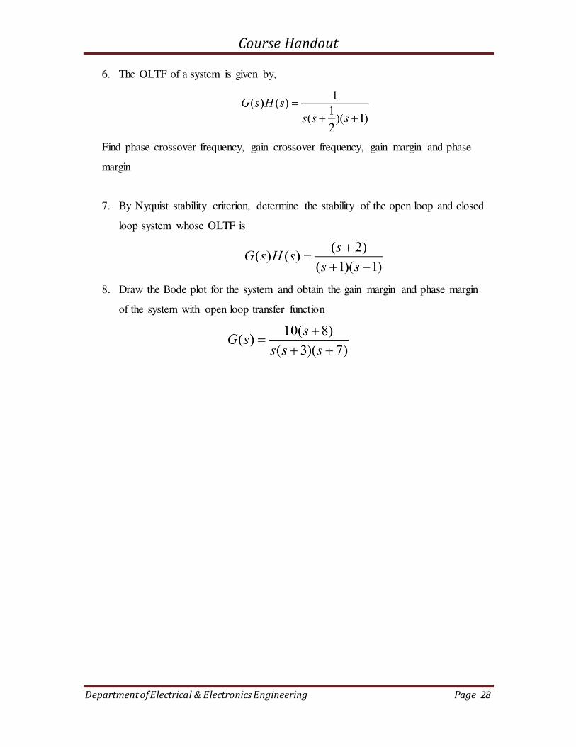
6. The OLTF of a system is given by,
Find phase crossover frequency, gain crossover frequency, gain margin and phase
margin
7. By Nyquist stability criterion, determine the stability of the open loop and closed
loop system whose OLTF is
8. Draw the Bode plot for the system and obtain the gain margin and phase margin
of the system with open loop transfer function
Course Handout
Department of Electrical & Electronics Engineering Page 29
2.4 ASSIGNMENTS
ASSIGNMENT 1
Prepare short Notes on the following topic
1. AC & DC Servo Motor
2. Synchro
3. Stepper Motor
4. Gyro
5. Tacho generator
Hint:
a) Each topic to be explained for - 6 Marks
b) Figure
c) Working Principle
d) Equations etc… to be included. Submission date : 30th August 2018 - Time 10:30AM
ASSIGNMENT 2
1. Draw the root locus for given closed loop systems
1. G(s) = k/ s(s2+4s +13)
2. G(s) = k/ s(s+2)(s+4)
3. G(s) = k/ s(s+6)(s2+4s +13)
Hint
a) Each Question carries - 12 Marks
b) Figure should be drawn in Normal graph paper
c) Each step should be included for drawing root locus
d) Equations etc… to be included. Submission date : 30th October 2018 - Time 10:30AM
Course Handout
Department of Electrical & Electronics Engineering Page 30
3. EE305 POWER ELECTRONICS

Course Handout
Department of Electrical & Electronics Engineering Page 31
3.1 COURSE INFORMATION SHEET
PROGRAMME: Electrical & Electronics
Engineering
DEGREE: B.TECH
COURSE: Power Electronics SEMESTER: V CREDITS: 3
COURSE CODE: EE 305
REGULATION: UG
COURSE TYPE: CORE
COURSE AREA/DOMAIN: Power
Electronics
CONTACT HOURS: 3+1 (Tutorial)
hours/Week.
CORRESPONDING LAB COURSE CODE
(IF ANY): Nil
LAB COURSE NAME: Nil
SYLLABUS:
UNIT DETAILS HOURS
I
SCR-Structure, static characteristics & switching (turn-on & turnoff)
characteristics - di/dt & dv/dt protection – turn-on methods of SCR -
two transistor analogy - series and parallel connection of SCRs
Structure and principle of operation of power diode, TRIAC, GTO,
Power MOSFET & IGBT – Comparison
6
II
Gate triggering circuits – R, RC, UJT triggering circuits – natural and
forced commutation (concept only). Requirements of isolation and
synchronisation in gate drive circuits- Opto and pulse transformer
based isolation. Controlled rectifiers – half-wave controlled rectifier
with R load – 1-phase fully controlled bridge rectifier with R, RL and
RLE loads (continuous & discontinuous conduction) – output voltage
equation – 1-phase half controlled bridge rectifier with R, RL and RLE
loads – displacement power factor – distortion factor.
8
III
3-phase half-wave controlled rectifier with R load – 3-phase fully
controlled & half-controlled converter with RLE load (continuous
conduction, ripple free) – output voltage equation-waveforms for
various triggering angles (no analysis) – 1-phase & 3-phase dual
converter with & without circulating current – four-quadrant operation
7
IV
Inverters – voltage source inverters– 1-phase half-bridge & full bridge
inverter with R & RL loads – THD in output voltage – 3phase bridge
inverter with R load – 120° & 180° conduction mode – current source
inverters.
7
V
Voltage control in inverters – Pulse Width Modulation – single pulse
width, multiple pulse width & sine PWM – modulation index &
frequency modulation ratio. AC voltage controllers (ACVC) – 1-
phase full-wave ACVC with R, & RL loads – waveforms – RMS
output voltage, input power factor with R load – sequence control (two
7

Course Handout
Department of Electrical & Electronics Engineering Page 32
stage) with R load
VI
DC-DC converters – step down and step up choppers – single quadrant,
two-quadrant & four quadrant chopper – pulse width modulation &
current limit control in dc-dc converters. Switching regulators – buck,
boost & buck-boost - continuous conduction mode only – waveforms
– design of filter inductance & capacitance
7
TOTAL HOURS 42
TEXT/REFERENCE BOOKS:
T/R BOOK TITLE/AUTHORS/PUBLICATION
T Muhammad H. Rashid, Power Electronics Circuits, Devices and Applications, Pearson Education
R 1. Mohan N., T. M. Undeland and W. P. Robbins., Power Electronics, Converters,
Applications & Design, Wiley-India
R 2. Krein P. T., Elements of Power Electronics, Oxford University Press, 1998.
R 3. P.S. Bimbhra, Power Electronics, Khanna Publishers, New Delhi
R 4. L. Umanand, Power Electronics – Essentials & Applications, Wiley-India
R 5. Singh M. D. and K. B. Khanchandani, Power Electronics, Tata McGraw Hill, New Delhi, 2008.
COURSE PRE-REQUISITES:
NIL
COURSE OBJECTIVES:
1
2
To get an overview of different types of power semiconductor devices and their switching characteristics
To study the operation and characteristics of various types of power electronic converters
COURSE OUTCOMES:
SNO DESCRIPTION BLOOMS’ TAXONOMY LEVEL
1 Choose appropriate power semiconductor device in
converter circuits and develop their triggering circuits.
Knowledge[Level 1],
Analysis[Level 4],
Application[Level 3]
2 Analyze various types of power electronic converters and
apply different switching techniques
Knowledge[Level 1],
Analysis[Level 4],
Application[Level 3]
Course Handout
Department of Electrical & Electronics Engineering Page 33
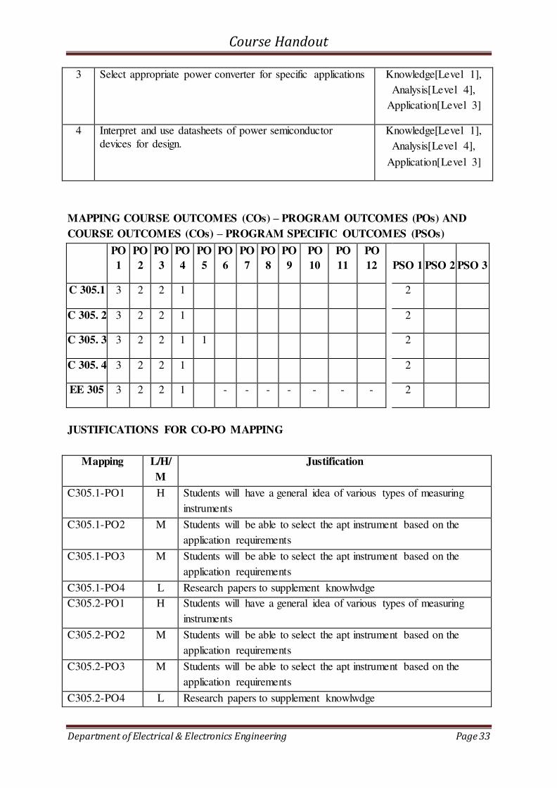
3 Select appropriate power converter for specific applications Knowledge[Level 1],
Analysis[Level 4],
Application[Level 3]
4 Interpret and use datasheets of power semiconductor
devices for design.
Knowledge[Level 1],
Analysis[Level 4],
Application[Level 3]
MAPPING COURSE OUTCOMES (COs) – PROGRAM OUTCOMES (POs) AND
COURSE OUTCOMES (COs) – PROGRAM SPECIFIC OUTCOMES (PSOs)
PO
1
PO
2
PO
3
PO
4
PO
5
PO
6
PO
7
PO
8
PO
9
PO
10
PO
11
PO
12
PSO 1 PSO 2 PSO 3
C 305.1 3 2 2 1 2
C 305. 2 3 2 2 1 2
C 305. 3 3 2 2 1 1 2
C 305. 4 3 2 2 1 2
EE 305 3 2 2 1 - - - - - - - 2
JUSTIFICATIONS FOR CO-PO MAPPING
Mapping L/H/
M
Justification
C305.1-PO1 H Students will have a general idea of various types of measuring
instruments
C305.1-PO2 M Students will be able to select the apt instrument based on the
application requirements
C305.1-PO3 M Students will be able to select the apt instrument based on the
application requirements
C305.1-PO4 L Research papers to supplement knowlwdge
C305.2-PO1 H Students will have a general idea of various types of measuring
instruments
C305.2-PO2 M Students will be able to select the apt instrument based on the
application requirements
C305.2-PO3 M Students will be able to select the apt instrument based on the
application requirements
C305.2-PO4 L Research papers to supplement knowlwdge
Course Handout
Department of Electrical & Electronics Engineering Page 34
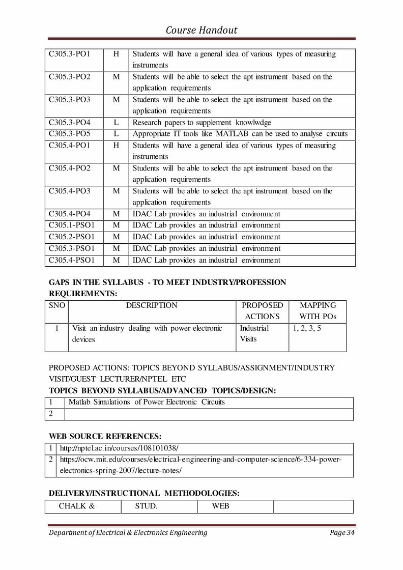
C305.3-PO1 H Students will have a general idea of various types of measuring
instruments
C305.3-PO2 M Students will be able to select the apt instrument based on the
application requirements
C305.3-PO3 M Students will be able to select the apt instrument based on the
application requirements
C305.3-PO4 L Research papers to supplement knowlwdge
C305.3-PO5 L Appropriate IT tools like MATLAB can be used to analyse circuits
C305.4-PO1 H Students will have a general idea of various types of measuring
instruments
C305.4-PO2 M Students will be able to select the apt instrument based on the
application requirements
C305.4-PO3 M Students will be able to select the apt instrument based on the
application requirements
C305.4-PO4 M IDAC Lab provides an industrial environment
C305.1-PSO1 M IDAC Lab provides an industrial environment
C305.2-PSO1 M IDAC Lab provides an industrial environment
C305.3-PSO1 M IDAC Lab provides an industrial environment
C305.4-PSO1 M IDAC Lab provides an industrial environment
GAPS IN THE SYLLABUS - TO MEET INDUSTRY/PROFESSION
REQUIREMENTS:
SNO DESCRIPTION PROPOSED
ACTIONS
MAPPING
WITH POs
1 Visit an industry dealing with power electronic
devices
Industrial
Visits
1, 2, 3, 5
PROPOSED ACTIONS: TOPICS BEYOND SYLLABUS/ASSIGNMENT/INDUSTRY
VISIT/GUEST LECTURER/NPTEL ETC
TOPICS BEYOND SYLLABUS/ADVANCED TOPICS/DESIGN:
1 Matlab Simulations of Power Electronic Circuits
2
WEB SOURCE REFERENCES:
1 http://nptel.ac.in/courses/108101038/
2 https://ocw.mit.edu/courses/electrical-engineering-and-computer-science/6-334-power-
electronics-spring-2007/lecture-notes/
DELIVERY/INSTRUCTIONAL METHODOLOGIES:
CHALK & STUD. WEB
Course Handout
Department of Electrical & Electronics Engineering Page 35
TALK ASSIGNMENT RESOURCES
LCD/SMART
BOARDS
STUD.
SEMINARS
ADD-ON
COURSES
ASSESSMENT METHODOLOGIES-DIRECT
ASSIGNMENTS STUD.
SEMINARS
TESTS/MODEL
EXAMS
UNIV.
EXAMINATION
STUD. LAB
PRACTICES
STUD. VIVA MINI/MAJOR
PROJECTS
CERTIFICATIONS
ADD-ON
COURSES
OTHERS
ASSESSMENT METHODOLOGIES-INDIRECT
ASSESSMENT OF COURSE
OUTCOMES (BY FEEDBACK, ONCE)
STUDENT FEEDBACK ON
FACULTY (TWICE)
ASSESSMENT OF MINI/MAJOR
PROJECTS BY EXT. EXPERTS
OTHERS
Prepared by Approved by
Caroline Ann Sam Dr. Unnikrishnan P.C
HOD EEE

Course Handout
Department of Electrical & Electronics Engineering Page 36
3.2 COURSE PLAN
Sl. No. Module Date Planned
1
1
Lec 1 Introduction to Power Electronics
2 Lec 2 SCR-Structure ,static characteristics
3 Lec 3
switching (turn-on & turnoff) characteristics
4 Lec 4
di/dt & dv/dt protection
5 Lec 5
turn-on methods of SCR - two transistor
analogy
6 Tut 1 Tutorial
7 Lec 6 series and parallel connection of SCRs
8 Lec 7
Structure and principle of operation of power
diode
9 Tut 2 Tutorial
10 Assignment 1 Submission
11
2
Lec 8 Gate triggering circuits – R, RC, UJT triggering
circuits
12
Lec 9
natural and forced commutation (concept only).
Requirements of isolation and synchronisation in
gate drive circuits- Opto and pulse transformer based isolation.
13 Lec 10
Controlled rectifiers – half-wave controlled
rectifier with R load
14
Lec 11
1-phase fully controlled bridge rectifier with R,
RL and RLE loads (continuous & discontinuous
conduction)
15 Tut 3 Tutorial
Lec 12
1-phase fully controlled bridge rectifier with R,
RL and RLE loads (continuous & discontinuous
conduction)
16
Lec 13
output voltage equation – 1-phase half controlled
bridge rectifier with R, RL and RLE loads
17
Lec 14
output voltage equation – 1-phase half controlled
bridge rectifier with R, RL and RLE loads

Course Handout
Department of Electrical & Electronics Engineering Page 37
18 Lec 15
displacement power factor – distortion factor.
19 Tut 4 Tutorial
20
3
3-phase half-wave controlled rectifier with R
load
21
Lec 16
3-phase fully controlled & half-controlled
converter with RLE load (continuous
conduction, ripple free)
22 Tut 5
output voltage equation-waveforms for various
triggering angles (no analysis)
23
Lec 17
1-phase & 3-phase dual converter with &
without circulating current – four-quadrant
operation
24 Tut 6 Tutorial
25 Lec 18
1-phase & 3-phase dual converter with &
without circulating current – four-quadrant
operation
26 Lec 19 Assignment 2 Submission
27
4
Lec 20 Inverters
28 tut 7 Tutorial
29 Lec 21 voltage source inverters
30 Lec 22
1-phase half-bridge & full bridge inverter with R
& RL loads
31 Lec 23
THD in output voltage – 3phase bridge inverter
with R load – 120° & 180° conduction mode.
32 tut 8 Tutorial
33 lec 24 current source inverters
34
5
lec 25 Voltage control in inverters
35 lec 26 Pulse Width Modulation – single pulse width
36 Tut 9 Tutorial
37 lec 27 multiple pulse width & sine PWM
38 lec 28
modulation index & frequency modulation ratio.
AC voltage controllers (ACVC)
39 lec 29
1-phase full-wave ACVC with R, & RL loads – waveforms
40 Tut 10 Tutorial
41
Lec 30
RMS output voltage, input power factor with R
load – sequence control (two stage) with R load
42 6 Lec 31
DC-DC converters – step down and step up
choppers
Course Handout
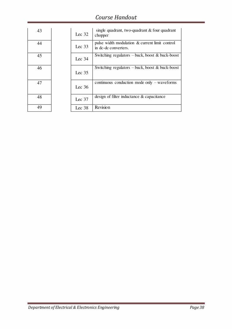
Department of Electrical & Electronics Engineering Page 38
43 Lec 32
single quadrant, two-quadrant & four quadrant
chopper
44 Lec 33
pulse width modulation & current limit control
in dc-dc converters.
45 Lec 34
Switching regulators – buck, boost & buck-boost
46 Lec 35
Switching regulators – buck, boost & buck-boost
47 Lec 36
continuous conduction mode only – waveforms
48 Lec 37
design of filter inductance & capacitance
49 Lec 38 Revision

Course Handout
Department of Electrical & Electronics Engineering Page 39
3.3 TUTORIALS
Tutorial 1
1. If a single-phase half-wave controlled rectifier using a thyristor has a purely resistive
load R and the delay angle 𝛼 = 𝜋2 , determine
a) Converter efficiency
b) Ripple factor,
c) Peak Inverse Voltage, PIV.
Tutorial 2

Course Handout
Department of Electrical & Electronics Engineering Page 40
3.4 ASSIGNMENTS
Assignment 1 Submission Date: On or before 24-08-2018
1. Compare and explain the construction and working principle of
a. TRIAC b. MOSFET c. .IGBT
d. GTO
Assignment 2 Submission Date: On or before 20-09-2018
1. Draw a three phase fully controlled bridge Converter with RL Load for α = 90◦, α =
120◦ and α = 150◦.
Assignment 3 Submission Date: On or before 5-10-2018
1. Explain the working principle of a Current Source Inverter.
Course Handout
Department of Electrical & Electronics Engineering Page 41
4. EE307 SIGNALS & SYSTEMS
Course Handout
Department of Electrical & Electronics Engineering Page 42
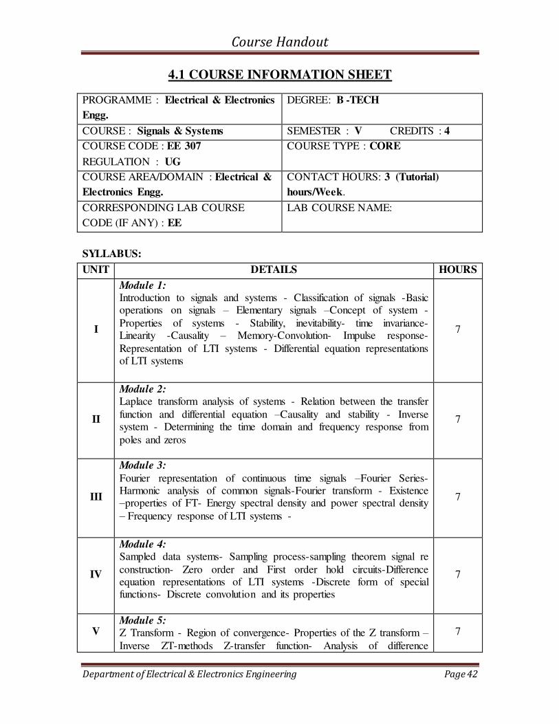
4.1 COURSE INFORMATION SHEET
PROGRAMME : Electrical & Electronics
Engg.
DEGREE: B -TECH
COURSE : Signals & Systems SEMESTER : V CREDITS : 4
COURSE CODE : EE 307
REGULATION : UG
COURSE TYPE : CORE
COURSE AREA/DOMAIN : Electrical &
Electronics Engg.
CONTACT HOURS: 3 (Tutorial)
hours/Week.
CORRESPONDING LAB COURSE
CODE (IF ANY) : EE
LAB COURSE NAME:
SYLLABUS:
UNIT DETAILS HOURS
I
Module 1: Introduction to signals and systems - Classification of signals -Basic operations on signals – Elementary signals –Concept of system -
Properties of systems - Stability, inevitability- time invariance- Linearity -Causality – Memory-Convolution- Impulse response-
Representation of LTI systems - Differential equation representations of LTI systems
7
II
Module 2: Laplace transform analysis of systems - Relation between the transfer
function and differential equation –Causality and stability - Inverse system - Determining the time domain and frequency response from
poles and zeros
7
III
Module 3:
Fourier representation of continuous time signals –Fourier Series-Harmonic analysis of common signals-Fourier transform - Existence –properties of FT- Energy spectral density and power spectral density
– Frequency response of LTI systems -
7
IV
Module 4: Sampled data systems- Sampling process-sampling theorem signal re
construction- Zero order and First order hold circuits-Difference equation representations of LTI systems -Discrete form of special functions- Discrete convolution and its properties
7
V Module 5: Z Transform - Region of convergence- Properties of the Z transform –Inverse ZT-methods Z-transfer function- Analysis of difference
7
Course Handout
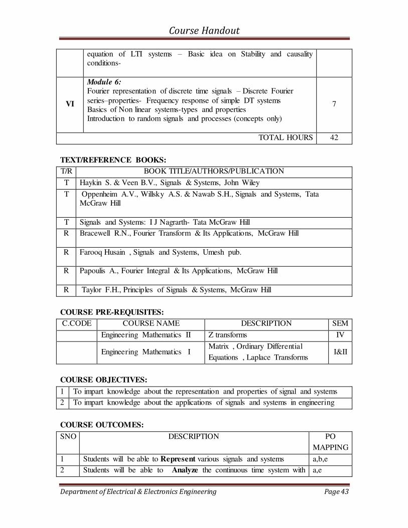
Department of Electrical & Electronics Engineering Page 43
equation of LTI systems – Basic idea on Stability and causality conditions-
VI
Module 6: Fourier representation of discrete time signals – Discrete Fourier
series–properties- Frequency response of simple DT systems Basics of Non linear systems-types and properties Introduction to random signals and processes (concepts only)
7
TOTAL HOURS 42
TEXT/REFERENCE BOOKS:
T/R BOOK TITLE/AUTHORS/PUBLICATION
T Haykin S. & Veen B.V., Signals & Systems, John Wiley
T Oppenheim A.V., Willsky A.S. & Nawab S.H., Signals and Systems, Tata McGraw Hill
T Signals and Systems: I J Nagrarth- Tata McGraw Hill
R Bracewell R.N., Fourier Transform & Its Applications, McGraw Hill
R Farooq Husain , Signals and Systems, Umesh pub.
R Papoulis A., Fourier Integral & Its Applications, McGraw Hill
R Taylor F.H., Principles of Signals & Systems, McGraw Hill
COURSE PRE-REQUISITES:
C.CODE COURSE NAME DESCRIPTION SEM
Engineering Mathematics II Z transforms IV
Engineering Mathematics I Matrix , Ordinary Differential
Equations , Laplace Transforms I&II
COURSE OBJECTIVES:
1 To impart knowledge about the representation and properties of signal and systems
2 To impart knowledge about the applications of signals and systems in engineering
COURSE OUTCOMES:
SNO DESCRIPTION PO
MAPPING
1 Students will be able to Represent various signals and systems a,b,e
2 Students will be able to Analyze the continuous time system with a,e
Course Handout
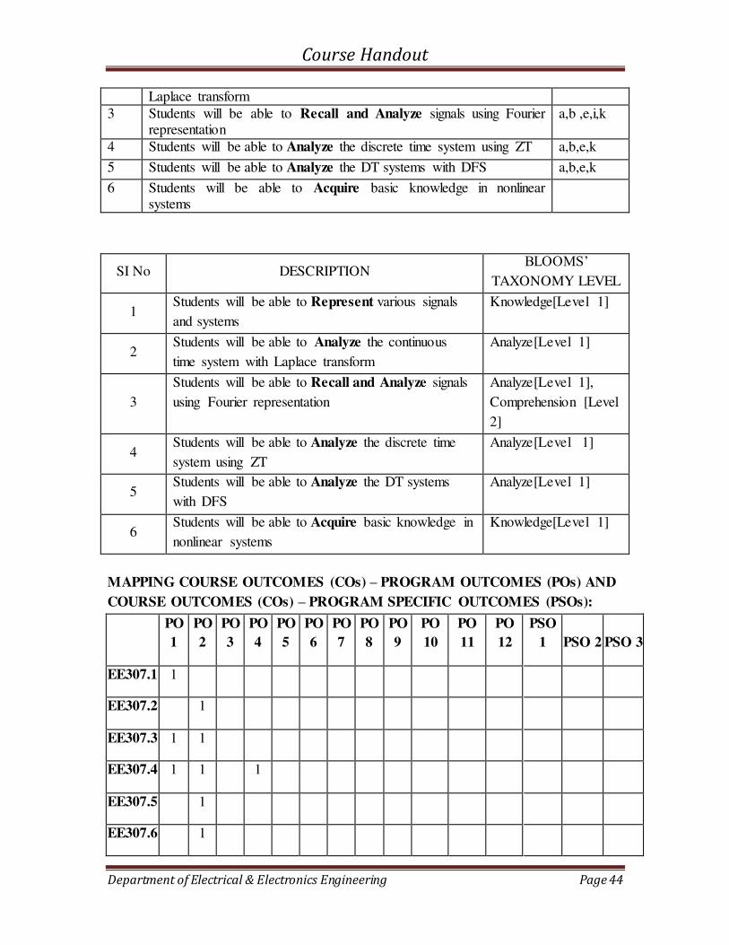
Department of Electrical & Electronics Engineering Page 44
Laplace transform
3 Students will be able to Recall and Analyze signals using Fourier representation
a,b ,e,i,k
4 Students will be able to Analyze the discrete time system using ZT a,b,e,k
5 Students will be able to Analyze the DT systems with DFS a,b,e,k
6 Students will be able to Acquire basic knowledge in nonlinear systems
SI No DESCRIPTION BLOOMS’
TAXONOMY LEVEL
1 Students will be able to Represent various signals
and systems
Knowledge[Level 1]
2 Students will be able to Analyze the continuous
time system with Laplace transform
Analyze[Level 1]
3
Students will be able to Recall and Analyze signals
using Fourier representation
Analyze[Level 1],
Comprehension [Level
2]
4 Students will be able to Analyze the discrete time
system using ZT
Analyze[Level 1]
5 Students will be able to Analyze the DT systems
with DFS
Analyze[Level 1]
6 Students will be able to Acquire basic knowledge in
nonlinear systems
Knowledge[Level 1]
MAPPING COURSE OUTCOMES (COs) – PROGRAM OUTCOMES (POs) AND
COURSE OUTCOMES (COs) – PROGRAM SPECIFIC OUTCOMES (PSOs):
PO
1
PO
2
PO
3
PO
4
PO
5
PO
6
PO
7
PO
8
PO
9
PO
10
PO
11
PO
12
PSO
1 PSO 2 PSO 3
EE307.1 1
EE307.2 1
EE307.3 1 1
EE307.4 1 1 1
EE307.5 1
EE307.6 1
Course Handout
Department of Electrical & Electronics Engineering Page 45
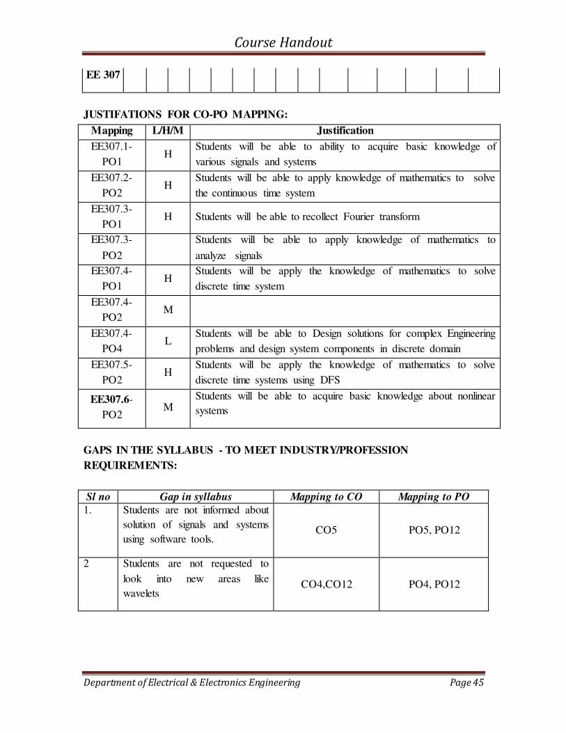
EE 307
JUSTIFATIONS FOR CO-PO MAPPING:
GAPS IN THE SYLLABUS - TO MEET INDUSTRY/PROFESSION
REQUIREMENTS:
Sl no Gap in syllabus Mapping to CO Mapping to PO
1. Students are not informed about
solution of signals and systems
using software tools. CO5 PO5, PO12
2 Students are not requested to
look into new areas like
wavelets CO4,CO12 PO4, PO12
Mapping L/H/M Justification
EE307.1-
PO1 H
Students will be able to ability to acquire basic knowledge of
various signals and systems
EE307.2-
PO2 H
Students will be able to apply knowledge of mathematics to solve
the continuous time system
EE307.3-
PO1 H Students will be able to recollect Fourier transform
EE307.3-
PO2
Students will be able to apply knowledge of mathematics to
analyze signals
EE307.4-
PO1 H
Students will be apply the knowledge of mathematics to solve
discrete time system
EE307.4-
PO2 M
EE307.4-
PO4 L
Students will be able to Design solutions for complex Engineering
problems and design system components in discrete domain
EE307.5-
PO2 H
Students will be apply the knowledge of mathematics to solve
discrete time systems using DFS
EE307.6-
PO2 M
Students will be able to acquire basic knowledge about nonlinear
systems
Course Handout
Department of Electrical & Electronics Engineering Page 46
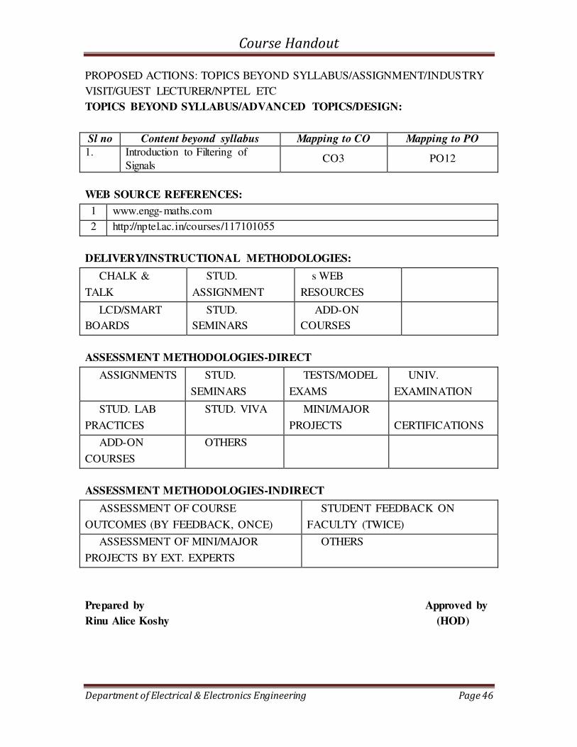
PROPOSED ACTIONS: TOPICS BEYOND SYLLABUS/ASSIGNMENT/INDUSTRY
VISIT/GUEST LECTURER/NPTEL ETC
TOPICS BEYOND SYLLABUS/ADVANCED TOPICS/DESIGN:
Sl no Content beyond syllabus Mapping to CO Mapping to PO
1. Introduction to Filtering of
Signals CO3 PO12
WEB SOURCE REFERENCES:
1 www.engg-maths.com
2 http://nptel.ac.in/courses/117101055
DELIVERY/INSTRUCTIONAL METHODOLOGIES:
CHALK &
TALK
STUD.
ASSIGNMENT
s WEB
RESOURCES
LCD/SMART
BOARDS
STUD.
SEMINARS
ADD-ON
COURSES
ASSESSMENT METHODOLOGIES-DIRECT
ASSIGNMENTS STUD.
SEMINARS
TESTS/MODEL
EXAMS
UNIV.
EXAMINATION
STUD. LAB
PRACTICES
STUD. VIVA MINI/MAJOR
PROJECTS
CERTIFICATIONS
ADD-ON
COURSES
OTHERS
ASSESSMENT METHODOLOGIES-INDIRECT
ASSESSMENT OF COURSE
OUTCOMES (BY FEEDBACK, ONCE)
STUDENT FEEDBACK ON
FACULTY (TWICE)
ASSESSMENT OF MINI/MAJOR
PROJECTS BY EXT. EXPERTS
OTHERS
Prepared by Approved by
Rinu Alice Koshy (HOD)

Course Handout
Department of Electrical & Electronics Engineering Page 47
4.2 COURSE PLAN
Sl. No Date Module Planned
1 Lecture1 1 Introduction to signals and systems -
Classification of Signals
2 Lecture2 1
Periodic and non-periodic signals, Problems
3 Lecture3 1
Even and Odd Signals, Problems
4 Tutorial 1 1 Causal, Anticausal, Non causal signals, Energy
and power signals, Problems
5 Lecture4 1
Deterministic and random signals, Problems
6 Tutorial 2 1 Problems on Energy and Power signals, Elementary signals
7 Tutorial 3 1 Basic operation on signals, Problems,
Introduction to systems
8 Lecture5 1 Classification of systems, Linear time invariant system, Checking time invariance
9 Lecture6 1 Representing Linear time invariant system,
Convolution Integral, Problems on convolution integral
10 Lecture7 2 Differential equation representation of LTI
systems, Laplace transform introduction
11 Lecture8 2 Causality, Stability and Invertibility of LTI
system. derivation on BIBO Stability
12 Lecture9 2 Solution of Differential equation by Laplace transform
13 Lecture10 2
Transfer function from differential equation.
14 Tutorial 4 2 Problems on differential equation and Laplace
transform
15 Tutorial 5 2 Determining the time domain and frequency response from poles and zeros
16 Lecture11 3
Fourier representation of continuous time signal
17 Lecture12 3 Fourier representation of continuous time signal-
Trigonometric series
18 Lecture13 3 Fourier representation of continuous time signal-Cosine representation
19 Lecture14 3 Fourier representation of continuous time signal-
complex exponential series representation
Course Handout
Department of Electrical & Electronics Engineering Page 48
20 Lecture15 3 Fourier Series-Harmonic analysis of common
signals, Problems
21 Lecture16 3 Fourier Series-Harmonic analysis of common
signals, Problems
22 Lecture17 4 Fourier transform - Condition for Existence –Properties of FT
23 Lecture18 4 Energy spectral density and power spectral
density
23 Lecture19 4 Frequency response of LTI systems, Problems on
Frequency response of LTI Systems
24 Lecture20 4 Sampled data systems- Sampling process-sampling theorem
25 Lecture21 4
Signal re construction- Zero order hold
26 Lecture22 5
Reconstruction using First order hold circuits
27 Lecture23 5 Difference equation representations of LTI systems ,Problems
28 Lecture24 5
Discrete convolution and its properties, Problems
29 Lecture25 5 Z Transform - Region of convergence- Properties
of the Z transform
30 Tutorial 6 5 Inverse ZT-methods Z-transfer function, Problems
31 Lecture26 6 Analysis of difference equation of LTI systems
,Problems
32 Lecture27 6 Basic idea on Stability and causality conditions,
Problems
33 Lecture28 6 Fourier series representation of discrete time signals – Discrete Fourier series
34 Lecture29 6
Tutorials on Discrete Fouries Series
35 Lecture30 6 Properties of Fourier series- Frequency response
of simple DT systems.
36 Lecture31 4 Tutorials on Energy spectral density and power spectral density
37 Lecture31 4 Energy spectral density and power spectral
density
Course Handout
Department of Electrical & Electronics Engineering Page 49
4.3 TUTORIALS
1. Check whether the system is linear or non linear dt
tdxtxty
)(2)(4)(
2. Check which of the following systems are causal?
a. y(t)=x(t)-x(t-1)
b. y(t)=x(t)+t
dx3
0
)(
c. y(t)=2x(t)+ dt
tdx )(
3. Test whether the following systems are time invariant
a. y(t)=2tx(t)
b. y(t)= 3x(t2)
4. Test the stability of the linear time invariant system whose impulse response are a. h(t)=e-5|t|
b. h(t)=t(cost)u(t) 5. Find the output y(t ) given
a. x(t)=cost u(t) & h(t)=tu(t)
b. x(t)= e-2tu(t) & h(t)= e-5tu(t)
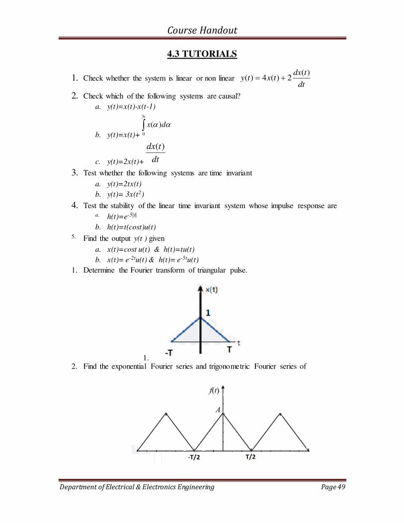
1. Determine the Fourier transform of triangular pulse.
1. 2. Find the exponential Fourier series and trigonometric Fourier series of
Course Handout
Department of Electrical & Electronics Engineering Page 50
3. Determine the convolution of )()( 2
1tuetx t and )()( 6
2 tuetx t using Fourier
transform.
4. Determine the magnitude spectrum of )()( tutetx at .
5. Find the Fourier transform of
elsewhere
tttx
0
101)(
2
Course Handout
Department of Electrical & Electronics Engineering Page 51
4.4 ASSIGNMENTS
ASSIGNMENT 1
Date of submission: 13 September 2018
1. Which are the causal and non causal systems? Justify the answer.
a. 12 tuetx t
b. 224
1
nunutx
n
c. ttx 2cos
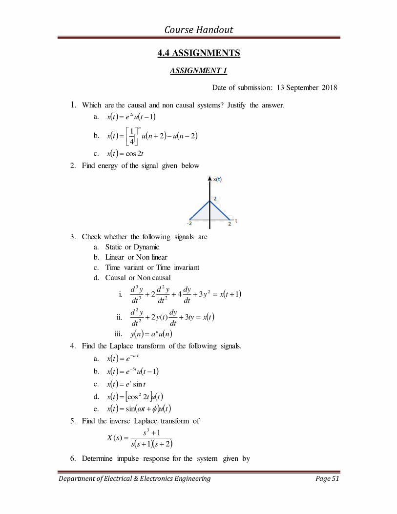
2. Find energy of the signal given below
3. Check whether the following signals are
a. Static or Dynamic
b. Linear or Non linear
c. Time variant or Time invariant
d. Causal or Non causal
i. 1342 2
2
2
3
3
txydt
dy
dt
yd
dt
yd
ii. txtydt
dyty
dt
yd 3)(2
2
2
iii. nuany n
4. Find the Laplace transform of the following signals.
a. taetx
b. 15 tuetx t
c. tetx t sin
d. tuttx 2cos2
e. tuttx sin
5. Find the inverse Laplace transform of
21
1)(
3
sss
ssX
6. Determine impulse response for the system given by
Course Handout
Department of Electrical & Electronics Engineering Page 52
)()(2
2
txtydt
ydTo
ASSIGNMENT 2
Date of Submission: October 2nd Week
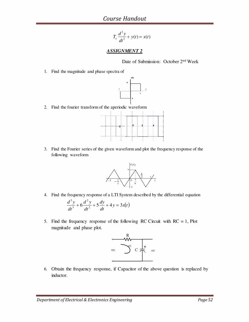
1. Find the magnitude and phase spectra of
2. Find the fourier transform of the aperiodic waveform
3. Find the Fourier series of the given waveform and plot the frequency response of the
following waveform
4. Find the frequency response of a LTI System described by the differential equation
txydt
dy
dt
yd
dt
yd3456
2
2
3
3
5. Find the frequency response of the following RC Circuit with RC = 1, Plot
magnitude and phase plot.
6. Obtain the frequency response, if Capacitor of the above question is replaced by
inductor.

Course Handout
Department of Electrical & Electronics Engineering Page 53
5. EE309 MICROPROCESSOR AND EMBEDDED
SYSTEMS
Course Handout
Department of Electrical & Electronics Engineering Page 54
5.1 COURSE INFORMATION SHEET
COURSE INFORMATION SHEET
PROGRAMME: Electrical & Electronics
Engineering
DEGREE: B.TECH
COURSE: Microprocessors and Embedded
Systems
SEMESTER: V CREDITS: 3
COURSE CODE: EE309 REGULATION: UG COURSE TYPE: CORE
COURSE AREA/DOMAIN: Microprocessors CONTACT HOURS: 3 hours/Week.
CORRESPONDING LAB COURSE CODE (IF
ANY):
LAB COURSE NAME:
SYLLABUS:
UNIT DETAILS HOURS
I
Internal architecture of 8085 microprocessor –Instruction set - Addressing
modes – Classification of instructions. Assembly language programming –standard programs in assembly language – code conversion, sorting –
binary and BCD arithmetic.
7
II
Stack and Subroutines – CALL and RETURN instructions – Delay
subroutines. Timing and control – Machine cycles, instruction cycle and T
states – fetch and execute cycles – Timing diagram for instructions.
7
III
IO and memory interfacing – Address decoding– interrupt structure of
8085. I/O ports- Programmable peripheral interface PPI 8255 - Modes of
operation. Interfacing of LEDs, ADC and DAC with 8085
7
IV
Introduction to Embedded Systems-Application domain of embedded systems,
features and characteristics, System model, Microprocessor Vs
Microcontroller, current trends and challenges, hard and soft real time
systems, Embedded product development, Life Cycle Management (water fall
model), Tool Chain System, Assemblers, Compilers, linkers, Loaders,
Debuggers Profilers & Test Coverage Tools
7
V
8051- Microcontrollers Hardware: Microcontroller Architecture: IO Port
structure, Register organization, general purpose RAM, Bit Addressable
RAM, Special Function Registers (SFRs). Instruction Set, addressing modes
Instruction Types.
7
VI
8051- assembly language programming, data types and directives, Time delay
and I/O port programming, Embedded Programming in C, data type and time
delay in C, I/O port programming, Timer / counter programming, serial port
programming, Interfacing – LCD, ADC, Stepper motor, and DAC.
7
TOTAL HOURS 42
TEXT/REFERENCE BOOKS:
T/R BOOK TITLE/AUTHORS/PUBLICATION
T Ramesh Gaonkar, Microprocessor, Architecture, Programming and Applications, Penram
International Publishing; Sixth edition, 2014.
T Mathur A., Introduction to Microprocessors, Tata McGraw Hill, New Delhi, 1992.
T Douglas V. Hall, Microprocessors and Interfacing, Tata McGraw Hill, Education, New
Delhi, Third Edition.

Course Handout
Department of Electrical & Electronics Engineering Page 55
T Rafiquzzaman, Microprocessor Theory and Application, PHI Learning, First Edition.
T Mohamed Ali Mazidi,Janice Gillispie Mazidi,” The 8051 microcontroller and embedded systems using Assembly and C”, 2/e, Pearson education /PHI
T Scott MacKenzie, Raphael C W Phan, “ The 8051 Microcontroller”, Fourth Edition, Pearson education
T Ray Ajoy and Burchandi, Advanced Microprocessor & Peripherals, Tata McGraw Hill,
Education, New Delhi, Second Edition.
COURSE PRE-REQUISITES:
C.CODE COURSE NAME DESCRIPTION SEM
EE 207 Computer Programming Basics of Programming in C III
COURSE OBJECTIVES:
1 To give an understanding on the Microprocessor 8085 and programming
2 To program 8085 microprocessor for different applications
3 To impart an insight into the architecture of 8051 microcontroller.
4 To develop sound understanding about programming and interfacing of 8051 microcontroller.
5 To give an understanding on the embedded system
6 To design an embedded system for different applications
COURSE OUTCOMES:
SNO DESCRIPTION Blooms’ Taxonomy Level
1 Students will be able to justify and explain the
use of microprocessors in different applications
Comprehension [Level 2]
2 Students will be able to choose and use a
microprocessor for an application.
Application [Level 3]
3 Students will be able to combine different
technologies for the betterment of society
Synthesis [Level 5]
4 Students will be able to develop an idea about
the basics of embedded systems and of
microcontrollers.
Knowledge [Level 1]
5 Students will be able to design and interface
microcontroller-based embedded systems.
Application [Level 3]
6 Students will be able to design different
embedded systems for different applications
Application [Level 3]
MAPPING COURSE OUTCOMES (COs) – PROGRAM OUTCOMES (POs) AND COURSE OUTCOMES (COs)
– PROGRAM SPECIFIC OUTCOMES (PSOs)
PO 1 PO 2 PO 3 PO 4 PO 5 PO 6 PO 7 PO 8 PO 9 PO 10 PO 11 PO 12 PSO 1 PSO 2 PSO 3
C 309.1 1 1 1 2 1 1 2 2 2 1
C 309. 2 1 1 1 2 2 1 1 1 1 2 2
C 309. 3 1 1 1 2 2 2 1 1 1
C 309. 4 2 2 1 1 1 1 1 1 2 1 1

Course Handout
Department of Electrical & Electronics Engineering Page 56
C 309. 5 2 2 2 1 1 2 2 2 1 1
C 309. 6 1 1 1 2 2 1 1 1 1 2 2
EE 309 1 1 2 2 2 1 2 2 1 2 2
JUSTIFATIONS FOR CO-PO MAPPING
Mapping L/M/H Justification
C309.1-PO1 L Students will be able to make use of the basic knowledge on
microprocessors to find solutions for the engineering problems
C309.1-PO2 L Students will be able to analyse engineering problems to reach conclusions
C309.1-PO3 L Students will be able to design solutions for complex engineering problems
C309.1-PO5 M Students will be able to apply modern techniques to model engineering
activities
C309.1-PO6 L Students will be able to make use of their knowledge for the betterment of
the society
C309.1-PO7 L Students will be able to give a sustainable and constructive development
for the society
C309.1-PO9 M Students will be able to work in a group with their background in
microprocessors
C309.1-P10 M Students will be able to communicate and comprehend properly in a group
work
C309.1-P11 M Students will be able to manage a project properly
C309.1-P12 L Students will be able to acquire more knowledge in the advanced fields of
processors
C309.2-PO1 L Students will be able to make use of the basic knowledge on
microprocessors to find solutions for the engineering problems
C309.2-PO2 L Students will be able to analyse engineering problems to reach conclusions
C309.2-PO3 L Students will be able to design solutions for complex engineering problems
C309.2-PO5 M Students will be able to apply modern techniques to model engineering
activities
C309.2-PO6 M Students will be able to make use of their knowledge for the betterment of
the society
C309.2-PO7 L Students will be able to give a sustainable and constructive development
for the society
C309.2-PO9 L Students will be able to work in a group with their background in
microprocessors
C309.2-P10 L Students will be able to communicate and comprehend properly in a group
work
C309.2-P11 L Students will be able to manage a project properly
C309.3-P01 L Students will be able to combine their knowledge for different applications
C309.3-PO2 L Students will be able to analyse engineering problems properly
C309.3-PO6 L Students will be able to make use of their knowledge for the betterment of
the society as a whole
C309.3-PO9 M Students will be able to work in a group understanding each other properly
C309.3-P1O M Students will be able to communicate the ideas properly
C309.3-P11 M Students will be able to handle a project considering the financial
Course Handout
Department of Electrical & Electronics Engineering Page 57
constraints too
C309.3-P12 L Students will be able to acquire good knowledge on advanced fields and
will help them to be familiar with advanced technologies.
C309.4-PO1 M Students will be able to reach solutions of many problems with the help of
basic knowledge in the embedded systems and microcontrollers.
C309.4-PO2 M The knowledge on the microcontroller and embedded system will help to
analyse the problem properly.
C309.4-PO3 L Students will be able to design solutions keeping in mind the safety of the
society.
C309.4-PO5 L Students will be at a better position to use the modern tools of IT for
solutions.
C309.4-PO6 L Students will have a better stand for the societal problems from the
perspective of an engineer
C309.4-PO7 L Students can help for a sustainable development with their proper
understanding of technology.
C309.4-PO9 L Students can contribute for a team work with their basic knowledge in
different fields.
C309.4-P11 L As a team students will be able to manage the team in a project in a better
way.
C309.4-P12 M For further development in their intellectual level the basics will be very
much helpful for students.
C309.5-P01 L Students will be able to combine their knowledge for different applications
C309.5-PO2 L Students will be able to analyse engineering problems properly
C309.5-PO6 L Students will be able to make use of their knowledge for the betterment of
the society as a whole
C309.5-PO9 M Students will be able to work in a group understanding each other properly
C309.5-P1O M Students will be able to communicate the ideas properly
C309.5-P11 M Students will be able to handle a project considering the financial
constraints too
C309.5-P12 L Students will be able to acquire good knowledge on advanced fields and
will help them to be familiar with advanced technologies.
C309.6-PO1 L Students will be able to make use of the basic knowledge on
microprocessors to find solutions for the engineering problems
C309.6-PO2 L Students will be able to analyse engineering problems to reach conclusions
C309.6-PO3 L Students will be able to design solutions for complex engineering problems
C309.6-PO5 M Students will be able to apply modern techniques to model engineering
activities
C309.6-PO6 M Students will be able to make use of their knowledge for the betterment of
the society
C309.6-PO7 L Students will be able to give a sustainable and constructive development
for the society
C309.6-PO9 L Students will be able to work in a group with their background in
microprocessors
C309.6-P10 L Students will be able to communicate and comprehend properly in a group
work
C309.6-P11 L Students will be able to manage a project properly
GAPS IN THE SYLLABUS - TO MEET INDUSTRY/PROFESSION REQUIREMENTS:

Course Handout
Department of Electrical & Electronics Engineering Page 58
SNO DESCRIPTION PROPOSED
ACTIONS
RELEVANCE
WITH POs
RELEVANCE
WITH PSOs
1. Real time experience of the
microprocessors
Lab Classes 1,6,7,12 1,3
2 Programming of the microprocessors
using software
Additional class 1,6,7,12 1,3
3 Programming using simulation software
MULTISIM.
Various
programming
examples using
MULTISIM.
3,5,9,11 1,3
PROPOSED ACTIONS: TOPICS BEYOND SYLLABUS/ASSIGNMENT/INDUSTRY VISIT/GUEST
LECTURER/NPTEL ETC
TOPICS BEYOND SYLLABUS/ADVANCED TOPICS/DESIGN:
SNO DESCRIPTION PROPOSED
ACTIONS
RELEVANCE
WITH POs
RELEVANCE
WITH PSOs
1 Advanced microprocessors to be introduced Additional
class
1,6,7,12 1,3
2 Software to program the microprocessors Additional
class
1,6,7,12 1,3
3 KEIL C programming for timers,
interrupts & serial communication.
Extra
Classes to
introduce
the same
3,5,9,11 1,3
4 Interfacing of 8255 PPI to 8051
microcontroller.
Extra
Classes to
introduce
the same
3,5,9,11 1,3
WEB SOURCE REFERENCES:
1 http://mvn.edu.in/mvnlms/mod/book/view.php?id=1394&chapterid=338 (Accessed on
02/08/2016)
2 http://8085microprocessor4u.blogspot.in/p/introduction-to-8085-1.html (Accessed on
02/08/2016)
3 http://www.daenotes.com/electronics/digital-electronics/Intel-8085-8-bit-microprocessor
(Accessed on 02/08/2016)
4 Microchip, / -pin 8-bit cmos flash microcontrollers, ds c datasheet, .
DELIVERY/INSTRUCTIONAL METHODOLOGIES:
CHALK & TALK STUD. ASSIGNMENT WEB RESOURCES
LCD/SMART
BOARDS
STUD. SEMINARS ADD-ON COURSES

Course Handout
Department of Electrical & Electronics Engineering Page 59
ASSESSMENT METHODOLOGIES-DIRECT
ASSIGNMENTS STUD. SEMINARS TESTS/MODEL
EXAMS
UNIV. EXAMINATION
STUD. LAB
PRACTICES
STUD. VIVA MINI/MAJOR
PROJECTS
CERTIFICATIONS
ADD-ON COURSES OTHERS
ASSESSMENT METHODOLOGIES-INDIRECT
ASSESSMENT OF COURSE OUTCOMES (BY
FEEDBACK, ONCE)
STUDENT FEEDBACK ON FACULTY (TWICE)
ASSESSMENT OF MINI/MAJOR PROJECTS BY
EXT. EXPERTS
OTHERS
Prepared by Approved by
Fr. Mejo Gracevilla CMI Dr. Unnikrishnan P.C.
HOD EEE

Course Handout
Department of Electrical & Electronics Engineering Page 60
5.2 COURSE PLAN
Sl
No. Module Day Topics
1
1
1 Introduction to the subject
2 2 Internal architecture of 8085 microprocessor
3 3 Instruction set Addressing modes
4 4 Instruction set Addressing modes
5 5 Classification of instructions
6 6 Assembly language programming
7 7 Standard programs in assembly language
8 8 Code conversion
9 9 Sorting of numbers
10 10 Binary and BCD arithmetic.
11
2
11 Stack and Subroutines
12 12 CALL and RETURN instructions
13 13 Delay subroutines
14 14 Delay subroutines
15 15 Timing and control
16 16 Machine cycles, instruction cycle and T states
17 17 Fetch and execute cycles
18 18 Timing diagram for instructions.
19
3
19 IO and memory interfacing
20 20 Address decoding
21 21 Interrupt structure of 8085
Course Handout
Department of Electrical & Electronics Engineering Page 61
22 22 I/O ports- Programmable peripheral interface PPI 8255
23 23 I/O ports- Programmable peripheral interface PPI 8255
24 24 Modes of operation
25 25 Interfacing of LEDs
26 26 ADC and DAC with 8085
27
5
27 Intel 8051 Microcontroller, Internal Architecture
28 28 I/O port structure,
29 29 Register organisation - general purpose RAM, Bit addressable RAM, register banks
30 30 Special function registers
31 31 Instruction set summary-addressing modes
32 32 Instruction types
35
6
35 Assembly language programming
36 36 Data types and directives
37 37 Time delay and I/O port programming
38 38 Embedded Programming in C, data type and time delay in
C
39 39 I/O port programming, Timer / counter programming
40 40 Serial port programming
41 41 Interfacing – LCD, ADC
42 42 Stepper motor, and DAC
43
4
43 Introduction to Embedded System
44 44 Application domain of embedded systems, features and characteristics
45 45 System model
46 46 Microprocessor Vs Microcontroller, current trends and
challenges
47 47 Hard and soft real time systems

Course Handout
Department of Electrical & Electronics Engineering Page 62
48 48 Embedded product development, Life Cycle Management
(water fall model)
49 49 Tool Chain System, Assemblers, Compilers
50 50 Linkers, Loaders, Debuggers Profilers & Test Coverage Tools

Course Handout
Department of Electrical & Electronics Engineering Page 63
5.3 TUTORIALS
1. Write an assembly level program to add two eight bit numbers. (8085)
2. Write an assembly level program to subtract two eight bit numbers. (8085)
3. Write an assembly level program to add two sixteen bit numbers.(8085)
4. Write an assembly level program to subtract two sixteen bit numbers.(8085)
5. Write an assembly level program to multiply two eight bit numbers by repeated
addition method.(8085)
6. Write an assembly level program to divide two eight bit numbers by repeated
subtraction method.(8085)
7. Write an assembly level program to find the sum of a data array.(8085)
8. Write an assembly level program to find the largest in a data array.(8085)
9. Write an assembly level program to find the smallest number in a data array.(8085)
10. Write an assembly level program to arrange a data array in ascending order.(8085)
11. Write an assembly level program to arrange a data array in descending order.(8085)
12. Write an assembly level program to find square from look-up table.(8085)
13. Interface the given ROM and RAM memories with the microprocessor.(8085)
14. Write an assembly level program to generate square wave for given frequency and
duty cycle.(8085)
15. Write a program to add two 8 bit numbers stored in Port 0 and Port 1. Send the result
to Port 2 and carry to Port 3.1.
16. Write a program to subtract two 8 bit numbers stored in Port 0 and Port 1. Send the
result to Port 2 and carry to Port 3.0.
17. Write a program to get the value of x from P1 and send x2 to P2 continuously.
18. Write a program to swap the nibbles of R0 and R1 so that low nibble of R0 swaps
with high nibble of R1 and high nobble of R0 with low nibble of R1.
19. You have five numbers stored in locations 40H to 44H. Check of any value equals
65H. If yes, copy its location to R4, else make R4=0.
20. Assume 5 BCD numbers are stores in locations starting from 40H. Write a program
to find the sum of all the numbers. Result should be in BCD and store in register R7
9MSB) and R6 (LSB).
21. Write a program to copy the value 55H into RAM locations 40H to 45H using (a)
direct addressing mode (b) register indirect addressing mode without a loop and (c)
with a loop
Course Handout
Department of Electrical & Electronics Engineering Page 64
22. For an 8051 system, with a crystal frequency of 11.0592 MHz, write a program to
generate a square wave on pin P1.0 with a duty cycle of 50%.
23. You have got the marks of 6 subjects out of 25d (19H). They are stored in locations
starting from 40H onwards. Find the average of your marks and store the result at
50H.
24. Write a program to convert a hexadecimal number to a decimal number
25. Write a program to read the temperature and test it for the value 75. According to the
test results, place the temperature value into the register indicated.
26. Ten hex numbers are stored in RAM locations 50H onwards. Write a program to find
the biggest number in the set. Save the biggest number in the location 60H.
27. Write an 8051 C program to send values 00-FF to port P1.
28. Write an 8051 C program to monitor bit P1.5. If it is high, send 55H to P0, otherwise
send AAH to P2.
29. Write an 8051 C program to get a byte of data from P0. If it is less than 100, send it
to P1, otherwise send it to P2.
30. Write an 8051 C program to toggle all the bits of P1 continuously.
31. Write an 8051 C program to toggle bits of P1 ports continuously with a 250 ms delay.
32. WAP to create a square wave of 50% duty cycle on the P1.5 bit. Use Timer 0 to
generate the time delay.
33. Assume XTAL = 11.0592 MHz, WAP to generate a square wave of 50 Hz frequency
on pin P2.3
34. Generate a square wave with on time of 3ms and off time of 10ms on P1.0. Assume
an XTAL of 22MHz.
35. Assume XTAL = 11.0592 MHz. WAP to generate a square of time period 4 sec on
P2.4.Use Timer 1 in mode 1.
36. Write an 8051 C program to generate a square wave with 50% duty cycle on P1.5.
Use Timer 0, 16-bit mode to generate the delay.
37. Assume XTAL = 11.0592 MHz. WAP to generate a square
wave with a frequency of 1835 Hz on pin P1.0.Use Timer 1 in mode 2.
38. Assume XTAL = 22 MHz, WAP to generate a square
wave of frequency 1kHz on pin P1.6. Use Timer 1 in mode 2.

Course Handout
Department of Electrical & Electronics Engineering Page 65
39. Design a counter for counting no. of pulses of an input signal for 1sec and display the
count at Port 2(LSB) & Port 1(MSB). The pulses are to be fed to pin P3.4.Use
XTAL=22 MHz.
40. Assume that a 1-Hz external clock is being fed into pin T1 (P3.5).Write a C program
for counter 1 in mode 2 (8-bit auto reload) to count up and display the state of the TL1
count on P1. Start the count at 0H.
Course Handout
Department of Electrical & Electronics Engineering Page 66
5.4 ASSIGNMENTS
Assignment 1 Submission Date: On or before 20 – 09 - 2018
1. Write a program to functions as a calculator.
1 for addition, 2 for subtraction, 3 for multiplication and 4 for division
2. Write a program to find the square of a number by odd number addition.
3. Write a program to find the square root of a number by odd number subtraction.
4. Write a program to find the numbers which are divisible by 3 from an array and store
those numbers in another array.
5. Write a program to find ‘n’ elements of the Fibonacci series and store in an array. (0, 1, 1, 2, 3, 5, 8, 13, 21, 34, 55, 89, ……………..)
6. Write a program to find the factorial of a number. (Including 6!)
Assignment 2 Submission Date: On or before 19 – 11 - 2018
1. Write a program to add two 8-bit numbers stored at external memory 2000H and
2001H, store the result at 2002H and carry at 2003H.
2. Write a program to subtract two 8-bit numbers stored at external memory 2000H
(Data 2) and 2001H (Data 1), store the result at 2002H and borrow at 2003H.
3. Write a program to multiply two 8-bit numbers stored at external memory 2000H and
2001H, store the result at 2002H and at 2003H.
4. Write a program to divide two 8-bit numbers stored at external memory 2000H (Data
2) and 2001H (Data 1), store the result at 2002H and at 2003H.
5. Write a program to find the average of an array of numbers given, the array starts
from 2000H, the first location gives the number of elements in the array, the result is
to be stored just after the array, consider that the sum of elements of the array be only
of 8-bits.
6. Sort the numbers in an array in descending order. The array starts from 2000H and the
first location contains the number of elements in the array.
7. Find the largest number in an array in which the array starts from 2000H and the first
location gives the number of elements in the array. The result is to be stored at the
location next to the array and the array is not to be disturbed.
Course Handout
Department of Electrical & Electronics Engineering Page 67
6. EE367 NEW & RENEWABLE SOURCES OF
ENERGY

Course Handout
Department of Electrical & Electronics Engineering Page 68
6.1 COURSE INFORMATION SHEET
PROGRAMME: Electrical & Electronics
Engineering
DEGREE: B.TECH
COURSE: New and Renewable Sources of
Energy
SEMESTER: V CREDITS: 3
COURSE CODE: EE367
REGULATION: UG
COURSE TYPE: ELECTIVE
COURSE AREA/DOMAIN: Renewable
Energy
CONTACT HOURS: 3 hours/Week.
CORRESPONDING LAB COURSE CODE
(IF ANY): Nil
LAB COURSE NAME: Nil
SYLLABUS:
UNIT DETAILS HOURS
I
Introduction, Classification of Energy Resources; Conventional Energy Resources - Availability and their limitations; Non-Conventional
Energy Resources – Classification, Advantages, Limitations; Comparison of Conventional and Non-Conventional Energy Resources; World Energy Scenario; Indian Energy Scenario. ENERGY
STORAGE: Sizing and Necessity of Energy Storage.
5
II
SOLAR THERMAL SYSTEMS: Introduction, Solar Constant, Basic Sun-Earth Angles, Measurement of Solar Radiation Data –
Pyranometer and Pyrheliometer .Principle of Conversion of Solar Radiation into Heat, – Solar thermal collectors – General description
and characteristics – Flat plate collectors – Heat transfer processes –
Solar concentrators (parabolic trough, parabolic dish, Central Tower Collector) –performance evaluation.
11
III
SOLAR ELECTRIC SYSTEMS: Solar Thermal Electric Power Generation –; Solar Photovoltaic – Solar Cell fundamentals, characteristics, classification, construction of module, panel and array.
Solar PV Systems – stand-alone and grid connected; Applications –
Street lighting, Domestic lighting and Solar Water pumping systems..
5
IV
ENERGY FROM OCEAN: Tidal Energy – Principle of Tidal Power,
Components of Tidal Power Plant (TPP), Classification of Tidal Power Plants, Advantages and Limitations of TPP. Ocean Thermal Energy
Conversion (OTEC): Principle of OTEC system, Methods of OTEC power generation – Open Cycle (Claude cycle), Closed Cycle (Anderson cycle) and Hybrid cycle (block diagram description of
OTEC); Site-selection criteria, Biofouling, Advantages & Limitations of OTEC.
7
V
WIND ENERGY: Introduction, Wind and its Properties, History of
Wind Energy, Wind Energy Scenario – World and India. Basic principles of Wind Energy Conversion Systems (WECS),
Classification of WECS, Parts of WECS, Derivation for Power in the wind, Electrical Power Output and Capacity Factor of WECS,
7
Course Handout
Department of Electrical & Electronics Engineering Page 69
Advantages and Disadvantages of WECS
VI
BIOMASS ENERGY: Introduction, Photosynthesis process, Biomass
fuels, Biomass conversion technologies, Urban waste to Energy Conversion, Biomass Gasification, Biomass to Ethanol Production, Biogas production from waste biomass, factors affecting biogas
generation, types of biogas plants – KVIC and Janata model; Biomass program in India. Small hydro power: Classification as micro, mini and
small hydro projects - Basic concepts and types of turbines - Design and selection considerations. EMERGING TECHNOLOGIES: Fuel Cell, Small Hydro Resources, Hydrogen Energy, alcohol energy,
nuclear fusion and power from satellite stations.
7
TOTAL HOURS 42
TEXT/REFERENCE BOOKS:
T/R BOOK TITLE/AUTHORS/PUBLICATION
T 1. A.A.M. Saigh (Ed): Solar Energy Engineering, Academic Press, 1977
T 2. Abbasi S. A. and N. Abbasi, Renewable Energy Sources and Their Environmental
Impact, Prentice Hall of India, 2001.
T 3. Boyle G. (ed.), Renewable Energy - Power for Sustainable Future, Oxford
University Press, 1996
R 4. Earnest J. and T. Wizelius, Wind Power Plants and Project Development, PHI
Learning, 2011.
R 5. F. Kreith and J.F. Kreider: Principles of Solar Engineering, McGraw Hill, 1978
R 6. G.N. Tiwari: Solar Energy-Fundamentals, Design, Modelling and Applications, Narosa Publishers, 2002
R 7. J.A. Duffie and W.A. Beckman: Solar Energy Thermal Processes, J. Wiley, 1994
R 8. Johansson T. B., H. Kelly, A. K. N. Reddy and R. H. Williams, Renewable
Energy – Sources for Fuel and Electricity, Earth scan Publications, London, 1993.
R 9. Khan B. H., Non-Conventional Energy Resources, Tata McGraw Hill, 2009.
R 10. Rao S. and B. B. Parulekar, Energy Technology, Khanna Publishers, 1999.
R 11. Sab S. L., Renewable and Novel Energy Sources, MI. Publications, 1995.
R 12. Sawhney G. S., Non-Conventional Energy Resources, PHI Learning, 2012.
R 13. Tiwari G. N., Solar Energy- Fundamentals, Design, Modelling and Applications,
CRC Press, 2002.
COURSE PRE-REQUISITES:
C.CODE COURSE NAME DESCRIPTION SEM
BE 103 Introduction to
Sustainable Engineering
Basic concepts in renewable energy I
COURSE OBJECTIVES:
1 To give sufficient knowledge about the promising new and renewable sources of
energy
To equip students in working with projects and to take up research work in
connected areas.

Course Handout
Department of Electrical & Electronics Engineering Page 70
COURSE OUTCOMES:
SNO DESCRIPTION Bloom’s Taxonomy Level
1 Students will be able to recognize and understand
the world and Indian energy scenario and
necessity of sustainable development utilising
Renewable Energy recourses.
Knowledge
[ Level 1 ]
2 Students will be able to analyse and infer the
potentials and design systems based on solar
thermal systems.
Analyze
[ Level 4 ]
3 Students will be able to illustrate, design and implement solar electric systems.
Apply [Level 3]
4 Students will be able to understand the
fundamentals and interpret basic components of energy from the ocean
Understand [Level 2]
5 Students will be able to understand the
fundamentals and interpret basic components of
energy from the wind
Understand
[Level 2]
6 Students will be able to understand the
fundamentals and interpret basic components of
energy from the biomass and emerging
technologies
Understand
[Level 2]
MAPPING COURSE OUTCOMES (COs) – PROGRAM OUTCOMES (POs) AND
COURSE OUTCOMES (COs) – PROGRAM SPECIFIC OUTCOMES (PSOs)
PO
1
PO
2
PO
3
PO
4
PO
5
PO
6
PO
7
PO
8
PO
9
PO
10
PO
11
PO
12
PSO 1 PSO 2 PSO 3
C 367.1 1 1 2 1 3 1
C 367. 2 2 3 3 2
C 367. 3 3 2 3 2 2
C 367. 4 2 2 1 2
C 367. 5 2 2 2 2 2 2
C 367.6 1 2 2 1 1 2
EE 367 1 1 2 1 1 2 2 - - 2 - 1 2 2 1

Course Handout
Department of Electrical & Electronics Engineering Page 71
JUSTIFICATIONS FOR CO-PO MAPPING
Mapping L/H/
M
Justification
C367.1-PO1 H Students will be able to explain and identify the energy scenario world
wide
C367.1-PO2 H Students will be able to formulate necessity of sustainable development
utilizing Renewable Energy recourses
C367.1-PO5 M Students will be able to identify renewable energy sources and suggest
the apt one for the society
C367.1-PO7 H Students will be able to understand the importance of Renewable energy
for sustainable development and importance of climate change
C367.1-PO10 M Students will be able to understand the importance of communication to
the society for sustainable development
C367.2-PO 2 M Students will be able to analyse and identify the problems on
sustainable development using solar thermal systems
C367.2-PO 3 H Students will be able to design solar thermal systems which is
required for the society to improve environmental conditions
C367.2-PO 7 H Students will be able to understand the Solar thermal systems that
will reduce the pollution in the Environment
C367.3-PO 3 M Students will be able to illustrate and design solar electric systems.
C367.3-PO 5 M Students will be able to apply modern tools to predict and analyse
the advantages and limitations of SPV systems
C367.3-PO 6 M Students will be able to become an Engineer to implement solar
based systems and benefit the society
C367.3-PO 7 H Students will be able to understand the Solar photovoltaic systems
that will reduce the pollution in the Environment
C367.4-PO 6 M Students will be able to become an Engineer to implement ocean
based systems and benefit the society
C367.4-PO 7 M Students will be able to understand the energy from the ocean that
will reduce the pollution in the Environment
C367.5-PO3 M Students will be able to illustrate and design wind electric systems
C367.5-PO4 L Students will be able to research, analyse and interpret data in the
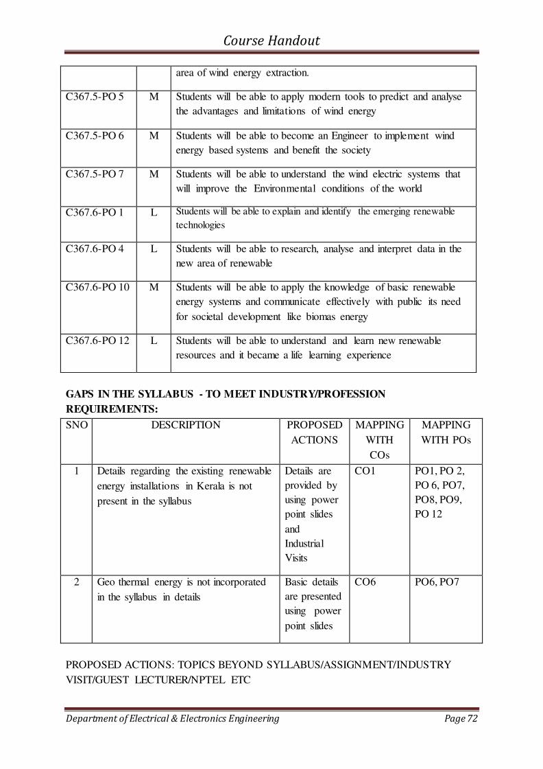
Course Handout
Department of Electrical & Electronics Engineering Page 72
area of wind energy extraction.
C367.5-PO 5 M Students will be able to apply modern tools to predict and analyse
the advantages and limitations of wind energy
C367.5-PO 6 M Students will be able to become an Engineer to implement wind
energy based systems and benefit the society
C367.5-PO 7 M Students will be able to understand the wind electric systems that
will improve the Environmental conditions of the world
C367.6-PO 1 L Students will be able to explain and identify the emerging renewable
technologies
C367.6-PO 4 L Students will be able to research, analyse and interpret data in the
new area of renewable
C367.6-PO 10 M Students will be able to apply the knowledge of basic renewable
energy systems and communicate effectively with public its need
for societal development like biomas energy
C367.6-PO 12 L Students will be able to understand and learn new renewable
resources and it became a life learning experience
GAPS IN THE SYLLABUS - TO MEET INDUSTRY/PROFESSION
REQUIREMENTS:
SNO DESCRIPTION PROPOSED
ACTIONS
MAPPING
WITH
COs
MAPPING
WITH POs
1 Details regarding the existing renewable
energy installations in Kerala is not
present in the syllabus
Details are
provided by
using power
point slides
and
Industrial
Visits
CO1 PO1, PO 2,
PO 6, PO7,
PO8, PO9,
PO 12
2 Geo thermal energy is not incorporated
in the syllabus in details
Basic details
are presented
using power
point slides
CO6 PO6, PO7
PROPOSED ACTIONS: TOPICS BEYOND SYLLABUS/ASSIGNMENT/INDUSTRY
VISIT/GUEST LECTURER/NPTEL ETC

Course Handout
Department of Electrical & Electronics Engineering Page 73
TOPICS BEYOND SYLLABUS/ADVANCED TOPICS/DESIGN:
Sl no Content beyond syllabus Mapping to
CO
Mapping to PO
1. Information regarding the climate change,
Paris agreement for climate change and
latest trends in the Renewable Energy
Industry is introduced to the students
CO1, CO6 PO3,PO7,PO12
WEB SOURCE REFERENCES:
1 www.nptel.iitm.ac.in
2 http://ocw.mit.edu/index.htm
3 Prof. G.D. Roy, Prof. N.K. De, Prof. T.K. Bhattacharya, Basic Electrical Technology,
www.nptel.com, retrieved on July 05, 2013 from URL:
http://nptel.iitm.ac.in/courses/Webcourse-contents/IIT%20Kharagpur
DELIVERY/INSTRUCTIONAL METHODOLOGIES:
CHALK &
TALK
STUD.
ASSIGNMENT
WEB
RESOURCES
LCD/SMART
BOARDS
STUD.
SEMINARS
ADD-ON
COURSES
ASSESSMENT METHODOLOGIES-DIRECT
ASSIGNMENTS STUD.
SEMINARS
TESTS/MODEL
EXAMS
UNIV.
EXAMINATION
STUD. LAB
PRACTICES
STUD. VIVA MINI/MAJOR
PROJECTS
CERTIFICATIONS
ADD-ON
COURSES
OTHERS
ASSESSMENT METHODOLOGIES-INDIRECT
ASSESSMENT OF COURSE
OUTCOMES (BY FEEDBACK, ONCE)
STUDENT FEEDBACK ON
FACULTY (TWICE)
ASSESSMENT OF MINI/MAJOR
PROJECTS BY EXT. EXPERTS
OTHERS
Prepared by Approved by
Ms. Ragam Rajagopal Dr. Unnikrishnan P.C.
HOD EEE

Course Handout
Department of Electrical & Electronics Engineering Page 74
6.2 COURSE PLAN
Lecture
(L) / Tutorial
(T)
Sr. No.
Day
Sr.No.
Topics
Module I
L1 Day 1 Introduction, Classification of Energy Resources
L2 Day 2 Conventional Energy
Resources - Availability and their limitations;
L3 Day 3 Non-Conventional Energy Resources – Classification, Advantages, Limitations
L4 Day 4 Non-Conventional
Energy Resources – Classification, Advantages, Limitations
L5 Day 5 Comparison of Conventional and Non-Conventional Energy Resources
L6 Day 6 World Energy Scenario;
L7 Day 7 Indian Energy Scenario
L8 Day 8 ENERGY
STORAGE: Sizing and Necessity of Energy Storage.
L9 Day9 SOLAR THERMAL SYSTEMS: Introduction, Solar Constant
L10 Day10 Basic Sun-Earth Angles
L11 & T1 Day11 Measurement of Solar Radiation Data
L12 Day12 Pyranometer and Pyrheliometer
L13 Day13 Principle of Conversion of Solar Radiation into Heat
L14 Day14 Solar thermal collectors – General description and characteristics
L15 Day15 Flat plate collectors – Heat transfer processes – Solar
concentrators
L16 & T2 Day16 Solar concentrators (parabolic trough, parabolic dish, Central Tower Collector) performance evaluation.
L17 Day 17 SOLAR ELECTRIC SYSTEMS: Solar Thermal Electric Power
Generation
L18 &T3 Day 18 Solar Photovoltaic – Solar Cell fundamentals
L19 Day 19 characteristics, classification,
L20 Day 20 construction of module, panel and array
L21 Day 21 Solar PV Systems – stand-alone
L22 Day 22 Solar PV Systems grid connected
L23 Day 23 Applications –
Street lighting, Domestic lighting and Solar Water pumping systems.
L24 Day 24 ENERGY FROM OCEAN: Tidal Energy – Principle of Tidal
Power
L25 Day 25 Components of Tidal Power Plant (TPP),
L26 Day 26 Classification of Tidal Power Plants, Advantages and Limitations of TPP
L27 Day 27 Ocean Thermal Energy
Conversion (OTEC): Principle of OTEC system
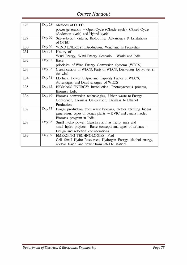
Course Handout
Department of Electrical & Electronics Engineering Page 75
L28 Day 28 Methods of OTEC
power generation – Open Cycle (Claude cycle), Closed Cycle (Anderson cycle) and Hybrid cycle
L29 Day 29 Site-selection criteria, Biofouling, Advantages & Limitations of OTEC.
L30 Day 30 WIND ENERGY: Introduction, Wind and its Properties
L31 Day 31 History of Wind Energy, Wind Energy Scenario – World and India
L32 Day 32 Basic
principles of Wind Energy Conversion Systems (WECS)
L33 Day 33 Classification of WECS, Parts of WECS, Derivation for Power in the wind
L34 Day 34 Electrical Power Output and Capacity Factor of WECS, Advantages and Disadvantages of WECS
L35 Day 35 BIOMASS ENERGY: Introduction, Photosynthesis process,
Biomass fuels,
L36 Day 36 Biomass conversion technologies, Urban waste to Energy Conversion, Biomass Gasification, Biomass to Ethanol
Production,
L37 Day 37 Biogas production from waste biomass, factors affecting biogas generation, types of biogas plants – KVIC and Janata model;
Biomass program in India.
L38 Day 38 Small hydro power: Classification as micro, mini and small hydro projects - Basic concepts and types of turbines –
Design and selection considerations
L39 Day 39 EMERGING TECHNOLOGIES: Fuel Cell, Small Hydro Resources, Hydrogen Energy, alcohol energy, nuclear fusion and power from satellite stations.
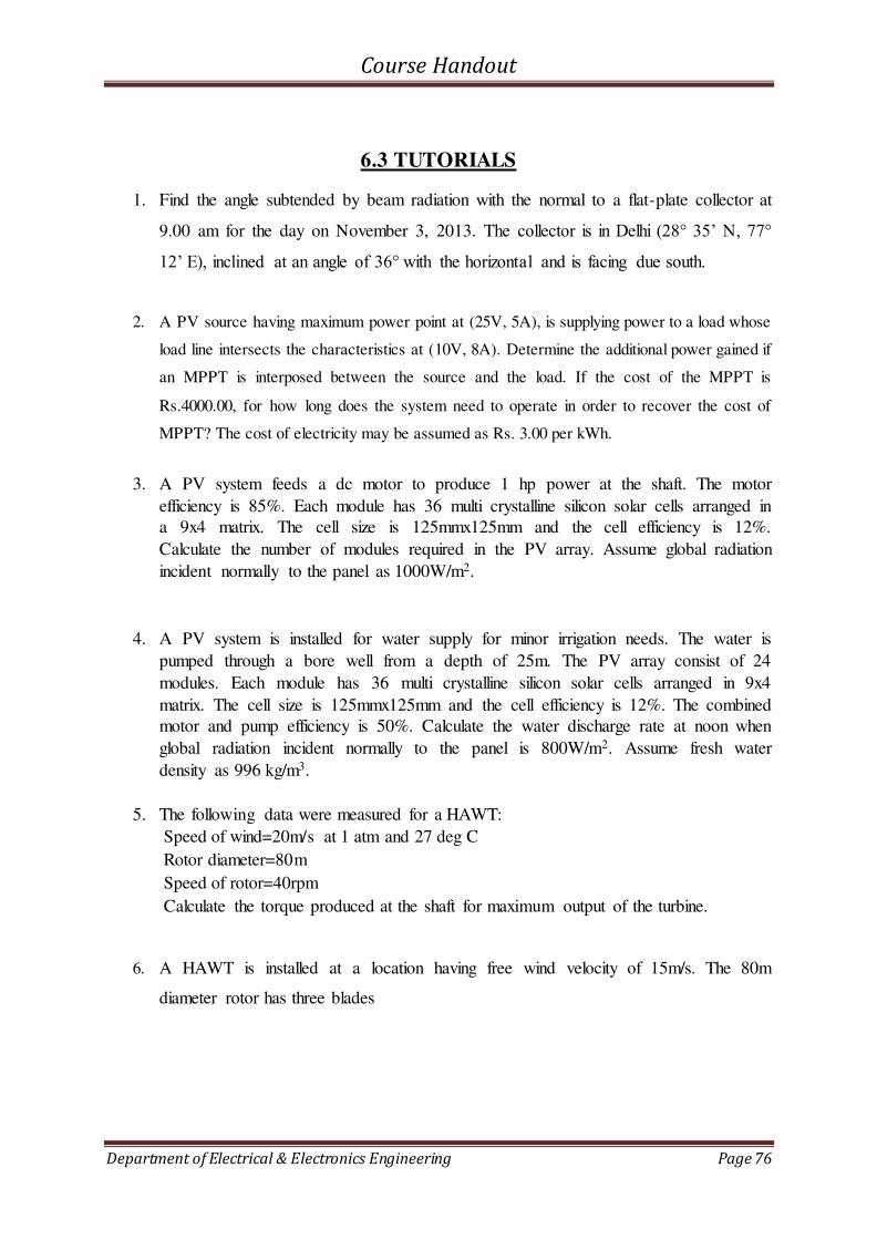
Course Handout
Department of Electrical & Electronics Engineering Page 76
6.3 TUTORIALS
1. Find the angle subtended by beam radiation with the normal to a flat-plate collector at
9.00 am for the day on November 3, 2013. The collector is in Delhi (28° 35’ N, 77°
12’ E), inclined at an angle of 36° with the horizontal and is facing due south.
2. A PV source having maximum power point at (25V, 5A), is supplying power to a load whose
load line intersects the characteristics at (10V, 8A). Determine the additional power gained if
an MPPT is interposed between the source and the load. If the cost of the MPPT is
Rs.4000.00, for how long does the system need to operate in order to recover the cost of
MPPT? The cost of electricity may be assumed as Rs. 3.00 per kWh.
3. A PV system feeds a dc motor to produce 1 hp power at the shaft. The motor
efficiency is 85%. Each module has 36 multi crystalline silicon solar cells arranged in
a 9x4 matrix. The cell size is 125mmx125mm and the cell efficiency is 12%.
Calculate the number of modules required in the PV array. Assume global radiation
incident normally to the panel as 1000W/m2.
4. A PV system is installed for water supply for minor irrigation needs. The water is
pumped through a bore well from a depth of 25m. The PV array consist of 24
modules. Each module has 36 multi crystalline silicon solar cells arranged in 9x4
matrix. The cell size is 125mmx125mm and the cell efficiency is 12%. The combined
motor and pump efficiency is 50%. Calculate the water discharge rate at noon when
global radiation incident normally to the panel is 800W/m2. Assume fresh water
density as 996 kg/m3.
5. The following data were measured for a HAWT:
Speed of wind=20m/s at 1 atm and 27 deg C
Rotor diameter=80m
Speed of rotor=40rpm
Calculate the torque produced at the shaft for maximum output of the turbine.
6. A HAWT is installed at a location having free wind velocity of 15m/s. The 80m
diameter rotor has three blades

Course Handout
Department of Electrical & Electronics Engineering Page 77
6.4 ASSIGNMENTS
Assignment I
Submit on/before: September 2nd week
1. Discuss Sizing and necessity of energy storage
2. Explain in detail about solar thermal electric power plant
Assignment II
Submit on/before: October 4th week
1. Explain following emerging technologies
a. Hydrogen energy
b. Alcohol energy
c. Nuclear fusion energy
d. Power from satellite stations
Course Handout
Department of Electrical & Electronics Engineering Page 78
7. EE369 HIGH VOLTAGE ENGINEERING
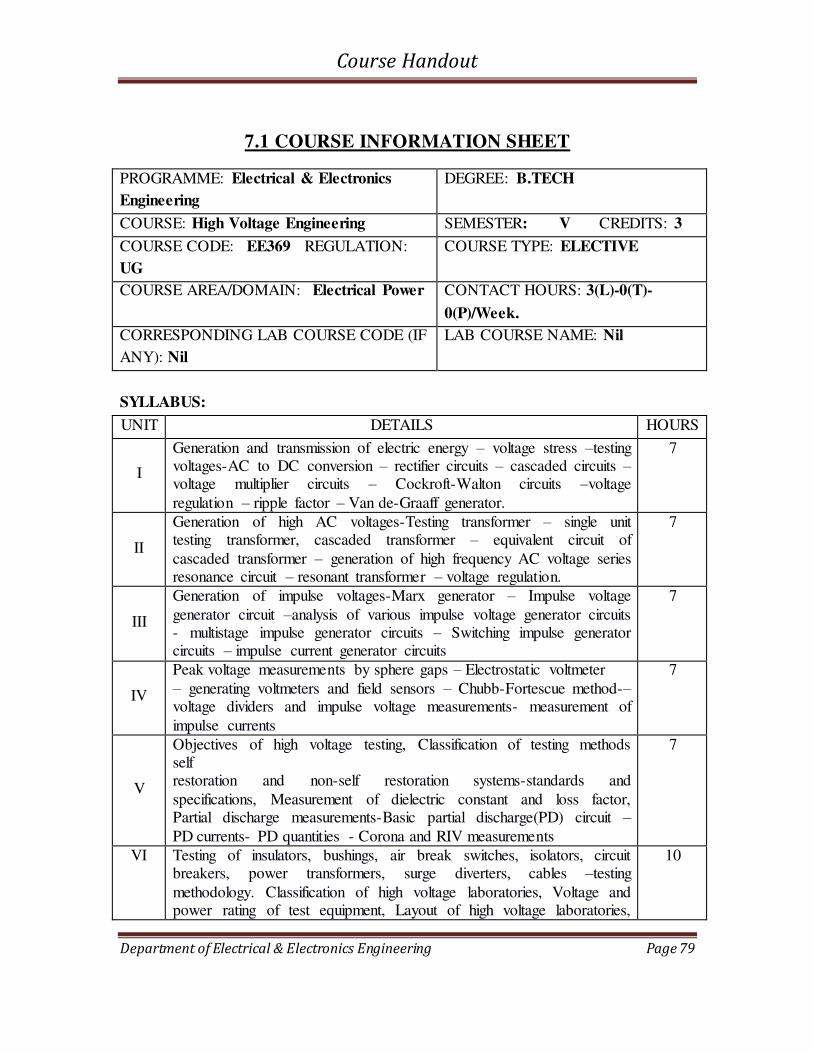
Course Handout
Department of Electrical & Electronics Engineering Page 79
7.1 COURSE INFORMATION SHEET
PROGRAMME: Electrical & Electronics
Engineering
DEGREE: B.TECH
COURSE: High Voltage Engineering SEMESTER: V CREDITS: 3
COURSE CODE: EE369 REGULATION:
UG
COURSE TYPE: ELECTIVE
COURSE AREA/DOMAIN: Electrical Power CONTACT HOURS: 3(L)-0(T)-
0(P)/Week.
CORRESPONDING LAB COURSE CODE (IF
ANY): Nil
LAB COURSE NAME: Nil
SYLLABUS:
UNIT DETAILS HOURS
I
Generation and transmission of electric energy – voltage stress –testing voltages-AC to DC conversion – rectifier circuits – cascaded circuits – voltage multiplier circuits – Cockroft-Walton circuits –voltage
regulation – ripple factor – Van de-Graaff generator.
7
II
Generation of high AC voltages-Testing transformer – single unit testing transformer, cascaded transformer – equivalent circuit of
cascaded transformer – generation of high frequency AC voltage series resonance circuit – resonant transformer – voltage regulation.
7
III
Generation of impulse voltages-Marx generator – Impulse voltage
generator circuit –analysis of various impulse voltage generator circuits - multistage impulse generator circuits – Switching impulse generator circuits – impulse current generator circuits
7
IV
Peak voltage measurements by sphere gaps – Electrostatic voltmeter
– generating voltmeters and field sensors – Chubb-Fortescue method-– voltage dividers and impulse voltage measurements- measurement of
impulse currents
7
V
Objectives of high voltage testing, Classification of testing methods self restoration and non-self restoration systems-standards and
specifications, Measurement of dielectric constant and loss factor, Partial discharge measurements-Basic partial discharge(PD) circuit –
PD currents- PD quantities - Corona and RIV measurements
7
VI Testing of insulators, bushings, air break switches, isolators, circuit breakers, power transformers, surge diverters, cables –testing
methodology. Classification of high voltage laboratories, Voltage and power rating of test equipment, Layout of high voltage laboratories,
10

Course Handout
Department of Electrical & Electronics Engineering Page 80
Grounding of impulse testing laboratories.
TOTAL HOURS 45
TEXT/REFERENCE BOOKS:
T/R BOOK TITLE/AUTHORS/PUBLICATION
T1 C.L Wadhwa High voltage Engineering, New age international (P) ltd, 2007
R1 Dieter Kind, Kurt Feser, “High voltage test techniques”, SBA Electrical Engineering Series, New Delhi, 1999.
R2 Kuffel, E., Zaengl, W.S. and Kuffel J., “High Voltage Engineering Fundamentals”, Elsvier India P Ltd, 2005
R3 Naidu M.S. and Kamaraju V., “High voltage Engineering”, Tata McGraw Hill Publishing Company Ltd., New Delhi, 2004.
COURSE PRE-REQUISITES:
C.CODE COURSE NAME DESCRIPTION SEM
BE101-
03
Introduction to Electrical
Engineering
Basic concepts in circuit theorems I
EE203 Analog Electronic circuits Basic Electronic Circuit
operations
III
EE206 Material Science Breakdown in Solid, Liquid and
Gaseous dielectrics
IV
EE208 Measurements and
Instrumentation
Different measuring methods and
instruments.
IV
COURSE OBJECTIVES:
1 The students will know several of methods of generating different test voltages, testing methods used in power equipments.
2 To provide basic knowledge in the area of design of high voltage laboratories.

Course Handout
Department of Electrical & Electronics Engineering Page 81
COURSE OUTCOMES:
SNO DESCRIPTION Blooms’ Taxonomy Level
1 Students will be able to understand the concepts of generation
of high voltage dc using Rectifier circuits, Cockroft Walton
Voltage Multiplier circuit and Electrostatic generator like Van
de Graaff generator.
Knowledge [Level
1]
Comprehension
[Level 2]
2 Students will be able to understand and compare the
generation of high voltage ac using cascaded transformers and
different type of resonant circuits like series, parallel and
series-parallel
Knowledge [Level
1]
Comprehension
[Level 2]
3 Students will be able to understand the generation of impulse
voltage generator circuits, Impulse current generator and
perform analysis of different type of impulse circuits.
Knowledge [Level
1]
Analysis [Level 4]
4 Students will be able to understand different measuring techniques like sphere gaps, Electrostatic voltmeter, voltage
dividers and impulse voltage & current measurements
Knowledge [Level
1]
5 Students will be able to classify different testing methods like self
restoration and non-self restoration systems and to understand
the measurement of partial discharges, dielectric loss, corona
and interference.
Knowledge [Level
1]
Application [Level
3]
6 Students will be able to understand the testing of various
power system components and to classify the high voltage
laboratories and to design the layout of high voltage
laboratories
Knowledge [Level
1]
Application [Level
3]
MAPPING COURSE OUTCOMES (COs)- PROGRAM OUTCOMES (POs) AND
COURSE OUTCOMES (COs) – PROGRAM SPECIFIC OUTCOMES (PSOs)
PO
1
PO
2
PO
3
PO
4
PO
5
PO
6
PO
7
PO
8
PO
9
PO
10
PO
11
PO
12
PSO
1
PSO
2
PSO
3
C 369.1 2 2 1
C 369.2 2 2 1

Course Handout
Department of Electrical & Electronics Engineering Page 82
C 369.3 2 2 1
C 369.4 2 2
C 369.5 2 2
C 369.6 2 2 2 2
EE 369 2 2 2 2 2 1
JUSTIFATIONS FOR CO-PO MAPPING
Mapping L/M/
H
Justification
C369.1-
PO1
M Student will be able to apply the knowledge gained from engineering
fundamentals electronic circuits like Rectifier circuits, Voltage Multiplier
circuit and Electrostatic generators for generation of high voltage dc .
C369.1-
PO3
M Student will be able to design system components for high voltage dc
generation using rectifier and voltage multiplier circuits and to meet
specific needs of voltage regulation and ripple factor.
C369.2-
PO1
M Student will be able to apply the knowledge gained from engineering
fundamentals of transformers and different type of resonant circuits and
apply that for generation of high voltage ac .
C369.2-
PO3
M Student will be able to understand how the cascaded transformer and
different type of resonant circuits are designed for generation of high
voltage ac.
C369.3-
PO1
M Student will be able to apply the knowledge gained from engineering
fundamentals for the generation of Impulse voltages and currents .
C369.3-
PO3
M Student will be able to design and compare the different circuit used for the
generation of Impulse voltages and currents .
C369.4-
PO1
M Student will be able to apply the knowledge gained from engineering
fundamentals to understand different techniques in measuring high voltages
like sphere gaps, Electrostatic voltmeter, voltage dividers and impulse
voltage & current measurements
C369.4- M Student will be able to understand the design aspects in measuring high

Course Handout
Department of Electrical & Electronics Engineering Page 83
PO3 voltages using sphere gaps, voltage dividers and impulse voltage & current
measurements
C369.5-
PO1
M Student will be able to apply the knowledge gained from engineering fundamentals in understanding different testing methods like self
restoration and non-self restoration systems and measurement of partial
discharges, dielectric loss, corona and interference.
C369.5-
PO3
M Student will be able understand the design aspects in measurement of partial
discharges, dielectric loss, corona and interference.
C369.6-
PO1
M Student will be able to apply the knowledge gained from engineering
fundamentals in understanding the testing of various power system
components like circuit breaker, surge arresters etc
C369.6-
PO4
M Students will be able to design the layout of high voltage laboratories with
experimental and interpreted datas.
C369.6-
PO6
M Students will be able to design the layout of high voltage laboratories with
social responsibility considering proper safety aspects
C369.6-
PO8
M Students will be able to design the layout of high voltage laboratories with
professional ethics and norms of engineering practices
GAPS IN THE SYLLABUS - TO MEET INDUSTRY/PROFESSIONAL
REQUIREMENTS:
SNO DESCRIPTION PROPOSED
ACTIONS
1. Practical exposure in high voltage
generation and measurement
Visit to high voltage labs at CPRI
/IIT/IISc
2. Recent trends in high voltage concepts Invited talk by experts /attending
seminars/workshops.
TOPICS BEYOND SYLLABUS/ADVANCED TOPICS/DESIGN:
1 Application of high voltage engineering
2 Overvoltage Phenomenon and insulation coordination in Electric power systems
WEB SOURCE REFERENCES:
1 www.nptel.iitm.ac.in –Reviewed date 2/07/2017

Course Handout
Department of Electrical & Electronics Engineering Page 84
DELIVERY/INSTRUCTIONAL METHODOLOGIES:
CHALK & TALK STUD.
ASSIGNMENT
WEB
RESOURCES
LCD/SMART
BOARDS
STUD.
SEMINARS
ADD-ON
COURSES
ASSESSMENT METHODOLOGIES-DIRECT
ASSIGNMENTS STUD.
SEMINARS
TESTS/MODEL
EXAMS
UNIV.
EXAMINATION
STUD. LAB
PRACTICES
STUD. VIVA MINI/MAJOR
PROJECTS
CERTIFICATIONS
ADD-ON
COURSES
OTHERS
ASSESSMENT METHODOLOGIES-INDIRECT
ASSESSMENT OF COURSE OUTCOMES
(BY FEEDBACK, ONCE)
STUDENT FEEDBACK ON
FACULTY (TWICE)
ASSESSMENT OF MINI/MAJOR
PROJECTS BY EXT. EXPERTS
OTHERS
Prepared by Approved by
Ms. Santhi.B
HOD EEE

Course Handout
Department of Electrical & Electronics Engineering Page 85
7.2 COURSE PLAN
Sl.No Module Planned
Date
Planned
1 1 L1 Introduction to subject and syllabus Generation-transmission of electric energy-Overall picture around the globe
2 1 L2 Voltage Stresses-Testing Voltages
3 1 L3 Generation of high voltage Dc-Basic concept-Rectifier
circuits(HWR)
4 1 L4 HWR-analysis-Simple voltage doubler circuit
5 1 L5 Cascaded voltage doubler circuit-Voltage multiplier circuit-Cockroft -Walton circuit-principle
6 1 L6
Cockroft -Walton circuit-Analysis-Ripple voltage & voltage
regulation
7 1 L7 Electrostatic generator-Van de-Graaff generator
8 2 L8 Generation of high AC voltages-Testing transformer – single unit testing transformer
9 2 L9 Gen. of high AC voltages-cascaded transformer-equivalent
circuit
10 2 L10 generation of high frequency AC voltage -series resonance circuit
11 2 L11 High freq AC gen-Resonant transformers
12 2 L12 Voltage regulation
13 2 L13 Problem-cascaded transformer-Resonant transformer
14 2 L14 summary on high voltage AC generation
15 3 L15 Generation of impulse voltages-different circuits-analysis
16 3 L16 Generation of impulse voltages-different circuits-analysis---continued
17 3 L17 multistage impulse generator circuits-Marx circuit-schematic diagram explanation-different components
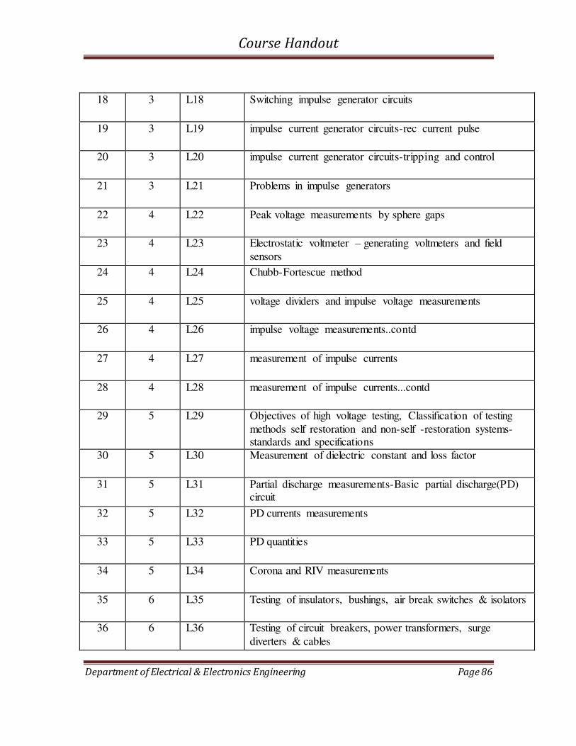
Course Handout
Department of Electrical & Electronics Engineering Page 86
18 3 L18 Switching impulse generator circuits
19 3 L19 impulse current generator circuits-rec current pulse
20 3 L20 impulse current generator circuits-tripping and control
21 3 L21 Problems in impulse generators
22 4 L22 Peak voltage measurements by sphere gaps
23 4 L23 Electrostatic voltmeter – generating voltmeters and field
sensors
24 4 L24 Chubb-Fortescue method
25 4 L25 voltage dividers and impulse voltage measurements
26 4 L26 impulse voltage measurements..contd
27 4 L27 measurement of impulse currents
28 4 L28 measurement of impulse currents...contd
29 5 L29 Objectives of high voltage testing, Classification of testing
methods self restoration and non-self -restoration systems-standards and specifications
30 5 L30 Measurement of dielectric constant and loss factor
31 5 L31 Partial discharge measurements-Basic partial discharge(PD) circuit
32 5 L32 PD currents measurements
33 5 L33 PD quantities
34 5 L34 Corona and RIV measurements
35 6 L35 Testing of insulators, bushings, air break switches & isolators
36 6 L36 Testing of circuit breakers, power transformers, surge
diverters & cables

Course Handout
Department of Electrical & Electronics Engineering Page 87
37 6 L37 Testing testing methodology. Classification of high voltage laboratories,
38 6 L38 Voltage and power rating of test equipment
39 6 L39 Layout of high voltage laboratories
40 6 L40 Grounding of impulse testing laboratories. Revision & univ Question Discussion

Course Handout
Department of Electrical & Electronics Engineering Page 88
7.3 ASSIGNMENTS
Assignment-I
`1. Briefly explain the recent applications in the field of High Voltage Engineering.
Due Date : 1st Week September
Assignment II
1. A Tesla coil has a primary winding rated for 10 kV. If L1, L2 and coefficient of coupling K are 10 mH, 200mH and 0.6 respectively find the peak value of the
output voltage if the capacitance in the primary side is 2microF and that on the secondary side is 1nF.Neglect the winding resistance. Find also the highest resonant frequency produced with the rated voltage applied.
2. An absolute electrostatic voltmeter has a movable circular plate 8cms in diameter.
If the distance between the plates during a measurement is 4mm, determine the potential difference when the force of attraction is 0.2 gm wt.
3. A 20 kV, 50Hz Schering bridge has a standard capacitance of 106 MicroF. In a test on a Bakelite sheet balance was obtained with a capacitance of 0.35 MicroF
in parallel with a non-inductive resistance of 318ohms,the non-inductive resistance in the remaining arm of the bridge being 130ohms..Determine the a)
equivalent series resistance and capacitance b) equivalent parallel resistance and capacitance and c)the p.f of the test specimen.
4. Following measurements are made to determine the dielectric constant and complex permittivity of a test specimen:
i. The air capacitance of the electrode system=50MicroF.
ii. The capacitance and loss angle of the electrodes with
specimen=190pF and 0.0085 respectively.
5. Why is grounding very important in an HV laboratory? Describe a typical grounding system used.
Due Date : 2nd Week November

Course Handout
Department of Electrical & Electronics Engineering Page 89
8. EE331 DIGITAL CIRCUITS AND EMBEDDED
SYSTEMS LAB

Course Handout
Department of Electrical & Electronics Engineering Page 90
8.1 COURSE INFORMATION SHEET
PROGRAMME: Electrical & Electronics
Engineering
DEGREE: B.TECH
COURSE: Digital Circuits and Embedded
Systems Lab
SEMESTER: V CREDITS: 1
COURSE CODE: EE 331
REGULATION: UG
COURSE TYPE:PRACTICAL
COURSE AREA/DOMAIN: Digital
Electronics
CONTACT HOURS: 3 hours/Week.
CORRESPONDING LAB COURSE CODE (IF
ANY):
LAB COURSE NAME:
SYLLABUS:
CYCLE DETAILS HOURS
I
A. DIGITAL CIRCUITS EXPERIMENTS:
(at least 7 experiments are mandatory)
1. Realisation of SOP & POS functions after K map reduction
2. Half adder & Full adder realization using NAND gates
3. 4-bit adder/subtractor & BCD adder using IC 7483
4. BCD to decimal decoder and BCD to 7-segment decoder & display
5. Study of multiplexer IC and Realization of combinational circuits using
multiplexers.
6. Study of counter ICs (7490, 7493)
7. Design of synchronous up, down & modulo N counters
8. Study of shift register IC 7495, ring counter and Johnsons counter
9. VHDL implementation of full adder, 4 bit magnitude comparator
24
II
B. EMBEDDED SYSTEM EXPERIMENTS:
(Out of first six, any two experiments using 8085 and any two
using 8086. Out of the last 3 experiments, any two experiments using 8051 or
any other open source hardware platforms like PIC, Arduino, MSP430, ARM etc)
( at least 5 experiments are mandatory)
1. Data transfer instructions using different addressing modes and block
transfer.
2. Arithmetic operations in binary and BCD-addition, subtraction, multiplication
and division
21
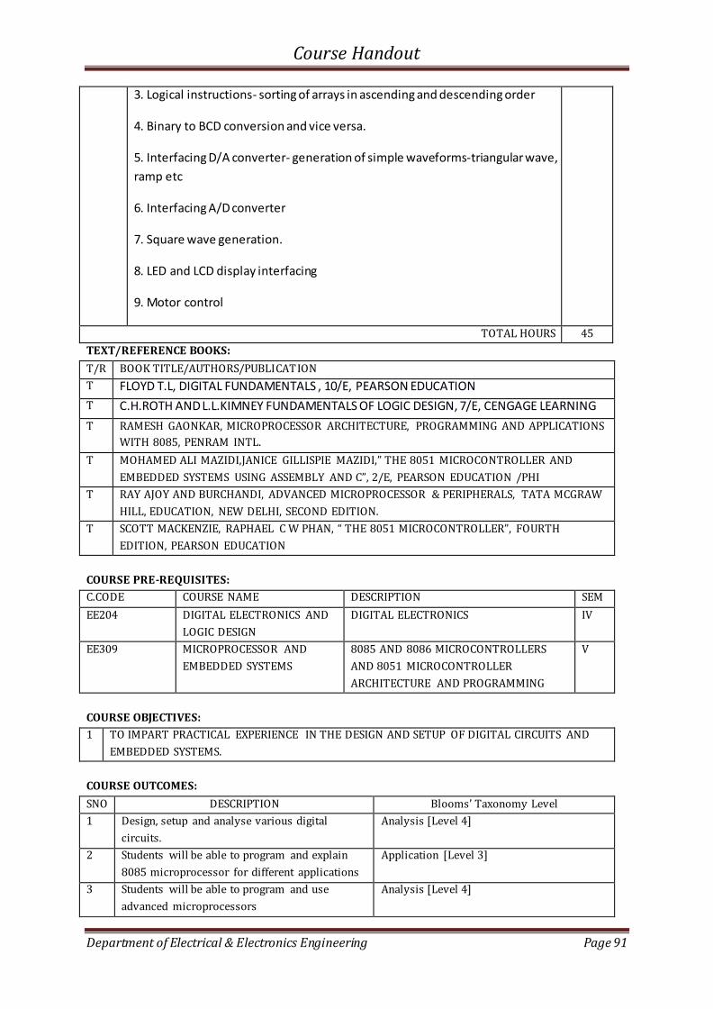
Course Handout
Department of Electrical & Electronics Engineering Page 91
3. Logical instructions- sorting of arrays in ascending and descending order
4. Binary to BCD conversion and vice versa.
5. Interfacing D/A converter- generation of simple waveforms-triangular wave,
ramp etc
6. Interfacing A/D converter
7. Square wave generation.
8. LED and LCD display interfacing
9. Motor control
TOTAL HOURS 45
TEXT/REFERENCE BOOKS:
T/R BOOK TITLE/AUTHORS/PUBLICATION
T FLOYD T.L, DIGITAL FUNDAMENTALS , 10/E, PEARSON EDUCATION
T C.H.ROTH AND L.L.KIMNEY FUNDAMENTALS OF LOGIC DESIGN, 7/E, CENGAGE LEARNING
T RAMESH GAONKAR, MICROPROCESSOR ARCHITECTURE, PROGRAMMING AND APPLICATIONS
WITH 8085, PENRAM INTL.
T MOHAMED ALI MAZIDI,JANICE GILLISPIE MAZIDI, THE 8 5 MICROCONTROLLER AND EMBEDDED SYSTEMS USING ASSEMBLY AND C , /E, PEARSON EDUCATION /PHI
T RAY AJOY AND BURCHANDI, ADVANCED MICROPROCESSOR & PERIPHERALS, TATA MCGRAW
HILL, EDUCATION, NEW DELHI, SECOND EDITION.
T SCOTT MACKENZIE, RAPHAEL C W PHAN, THE 8 5 MICROCONTROLLER , FOURTH EDITION, PEARSON EDUCATION
COURSE PRE-REQUISITES:
C.CODE COURSE NAME DESCRIPTION SEM
EE204 DIGITAL ELECTRONICS AND
LOGIC DESIGN
DIGITAL ELECTRONICS IV
EE309 MICROPROCESSOR AND
EMBEDDED SYSTEMS
8085 AND 8086 MICROCONTROLLERS
AND 8051 MICROCONTROLLER
ARCHITECTURE AND PROGRAMMING
V
COURSE OBJECTIVES:
1 TO IMPART PRACTICAL EXPERIENCE IN THE DESIGN AND SETUP OF DIGITAL CIRCUITS AND
EMBEDDED SYSTEMS.
COURSE OUTCOMES:
SNO DESCRIPTION Blooms’ Taxonomy Level
1 Design, setup and analyse various digital
circuits.
Analysis [Level 4]
2 Students will be able to program and explain
8085 microprocessor for different applications
Application [Level 3]
3 Students will be able to program and use
advanced microprocessors
Analysis [Level 4]
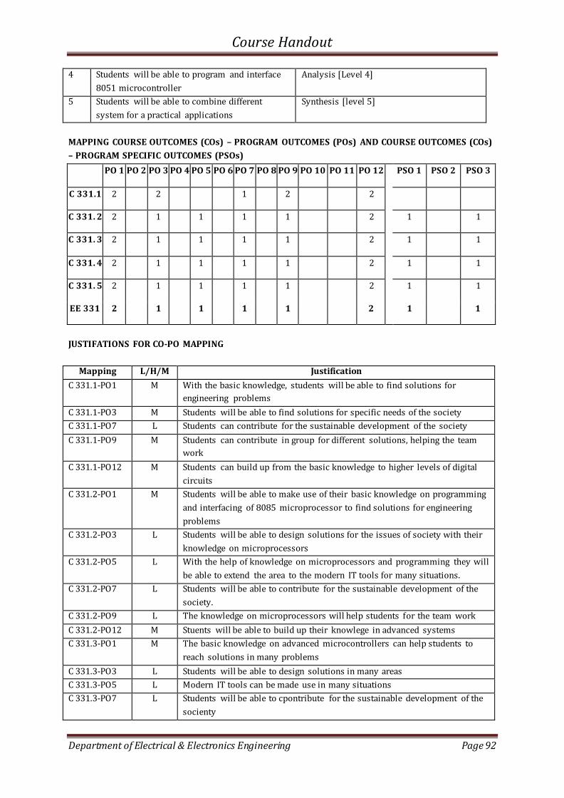
Course Handout
Department of Electrical & Electronics Engineering Page 92
4 Students will be able to program and interface
8051 microcontroller
Analysis [Level 4]
5 Students will be able to combine different
system for a practical applications
Synthesis [level 5]
MAPPING COURSE OUTCOMES (COs) – PROGRAM OUTCOMES (POs) AND COURSE OUTCOMES (COs)
– PROGRAM SPECIFIC OUTCOMES (PSOs)
PO 1 PO 2 PO 3 PO 4 PO 5 PO 6 PO 7 PO 8 PO 9 PO 10 PO 11 PO 12 PSO 1 PSO 2 PSO 3
C 331.1 2 2 1 2 2
C 331. 2 2 1 1 1 1 2 1 1
C 331. 3 2 1 1 1 1 2 1 1
C 331. 4 2 1 1 1 1 2 1 1
C 331. 5 2 1 1 1 1 2 1 1
EE 331 2 1 1 1 1 2 1 1
JUSTIFATIONS FOR CO-PO MAPPING
Mapping L/H/M Justification
C 331.1-PO1 M With the basic knowledge, students will be able to find solutions for
engineering problems
C 331.1-PO3 M Students will be able to find solutions for specific needs of the society
C 331.1-PO7 L Students can contribute for the sustainable development of the society
C 331.1-PO9 M Students can contribute in group for different solutions, helping the team
work
C 331.1-PO12 M Students can build up from the basic knowledge to higher levels of digital
circuits
C 331.2-PO1 M Students will be able to make use of their basic knowledge on programming
and interfacing of 8085 microprocessor to find solutions for engineering
problems
C 331.2-PO3 L Students will be able to design solutions for the issues of society with their
knowledge on microprocessors
C 331.2-PO5 L With the help of knowledge on microprocessors and programming they will
be able to extend the area to the modern IT tools for many situations.
C 331.2-PO7 L Students will be able to contribute for the sustainable development of the
society.
C 331.2-PO9 L The knowledge on microprocessors will help students for the team work
C 331.2-PO12 M Stuents will be able to build up their knowlege in advanced systems
C 331.3-PO1 M The basic knowledge on advanced microcontrollers can help students to
reach solutions in many problems
C 331.3-PO3 L Students will be able to design solutions in many areas
C 331.3-PO5 L Modern IT tools can be made use in many situations
C 331.3-PO7 L Students will be able to cpontribute for the sustainable development of the
socienty
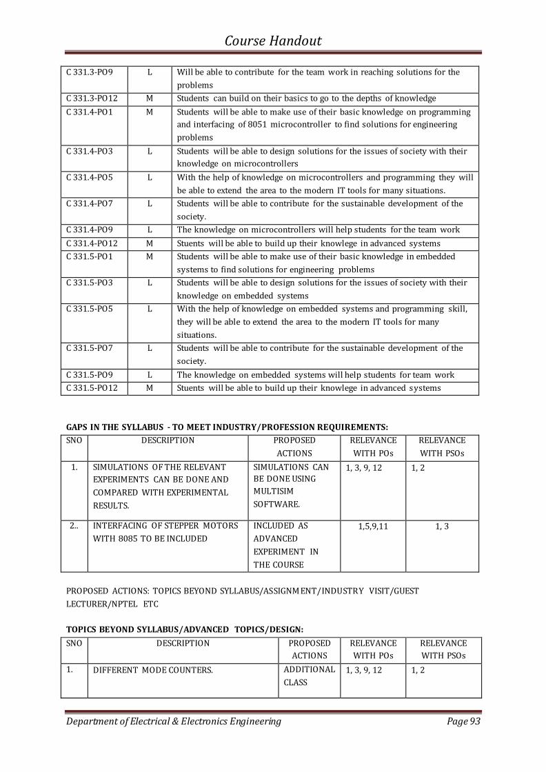
Course Handout
Department of Electrical & Electronics Engineering Page 93
C 331.3-PO9 L Will be able to contribute for the team work in reaching solutions for the
problems
C 331.3-PO12 M Students can build on their basics to go to the depths of knowledge
C 331.4-PO1 M Students will be able to make use of their basic knowledge on programming
and interfacing of 8051 microcontroller to find solutions for engineering
problems
C 331.4-PO3 L Students will be able to design solutions for the issues of society with their
knowledge on microcontrollers
C 331.4-PO5 L With the help of knowledge on microcontrollers and programming they will
be able to extend the area to the modern IT tools for many situations.
C 331.4-PO7 L Students will be able to contribute for the sustainable development of the
society.
C 331.4-PO9 L The knowledge on microcontrollers will help students for the team work
C 331.4-PO12 M Stuents will be able to build up their knowlege in advanced systems
C 331.5-PO1 M Students will be able to make use of their basic knowledge in embedded
systems to find solutions for engineering problems
C 331.5-PO3 L Students will be able to design solutions for the issues of society with their
knowledge on embedded systems
C 331.5-PO5 L With the help of knowledge on embedded systems and programming skill,
they will be able to extend the area to the modern IT tools for many
situations.
C 331.5-PO7 L Students will be able to contribute for the sustainable development of the
society.
C 331.5-PO9 L The knowledge on embedded systems will help students for team work
C 331.5-PO12 M Stuents will be able to build up their knowlege in advanced systems
GAPS IN THE SYLLABUS - TO MEET INDUSTRY/PROFESSION REQUIREMENTS:
SNO DESCRIPTION PROPOSED
ACTIONS
RELEVANCE
WITH POs
RELEVANCE
WITH PSOs
1. SIMULATIONS OF THE RELEVANT
EXPERIMENTS CAN BE DONE AND
COMPARED WITH EXPERIMENTAL
RESULTS.
SIMULATIONS CAN
BE DONE USING
MULTISIM
SOFTWARE.
1, 3, 9, 12 1, 2
2.. INTERFACING OF STEPPER MOTORS
WITH 8085 TO BE INCLUDED
INCLUDED AS
ADVANCED
EXPERIMENT IN
THE COURSE
1,5,9,11 1, 3
PROPOSED ACTIONS: TOPICS BEYOND SYLLABUS/ASSIGNMENT/INDUSTRY VISIT/GUEST
LECTURER/NPTEL ETC
TOPICS BEYOND SYLLABUS/ADVANCED TOPICS/DESIGN:
SNO DESCRIPTION PROPOSED
ACTIONS
RELEVANCE
WITH POs
RELEVANCE
WITH PSOs
1. DIFFERENT MODE COUNTERS. ADDITIONAL
CLASS
1, 3, 9, 12 1, 2
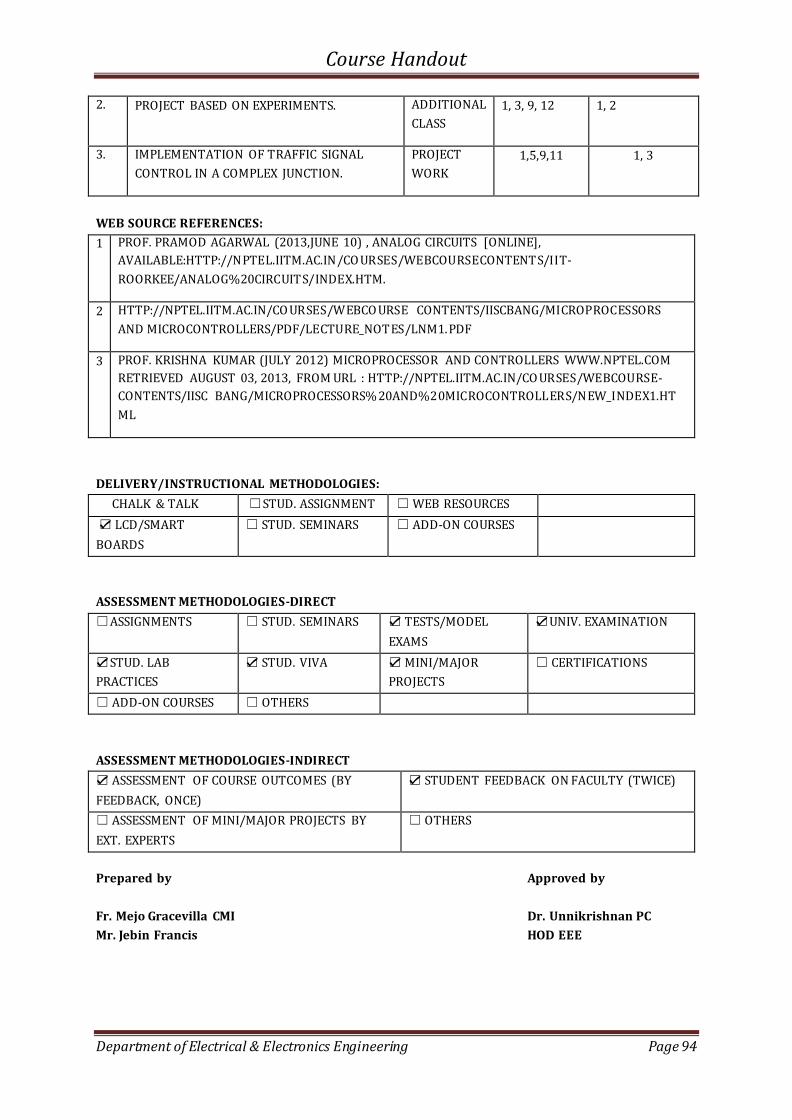
Course Handout
Department of Electrical & Electronics Engineering Page 94
2. PROJECT BASED ON EXPERIMENTS. ADDITIONAL
CLASS
1, 3, 9, 12 1, 2
3. IMPLEMENTATION OF TRAFFIC SIGNAL
CONTROL IN A COMPLEX JUNCTION.
PROJECT
WORK
1,5,9,11 1, 3
WEB SOURCE REFERENCES:
1 PROF. PRAMOD AGARWAL (2013,JUNE 10) , ANALOG CIRCUITS [ONLINE],
AVAILABLE:HTTP://NPTEL.IITM.AC.IN/CO URSES/WEBCOURSECONTENTS/IIT-
ROORKEE/ANALOG%20CIRCUITS/INDEX.HTM.
2 HTTP://NPTEL.IITM.AC.IN/CO URSES/WEBCO URSE CONTENTS/IISCBANG/MICROPROCESSORS
AND MICROCONTROLLERS/PDF/LECTURE_NOTES/LNM1.PDF
3 PROF. KRISHNA KUMAR (JULY 2012) MICROPROCESSOR AND CONTROLLERS WWW.NPTEL.COM
RETRIEVED AUGUST 03, 2013, FROM URL : HTTP://NPTEL.IITM.AC.IN/CO URSES/WEBCOURSE-
CONTENTS/IISC BANG/MICROPROCESSORS% 20AND%20MICROCONTROLLERS/NEW_INDEX1.HT
ML
DELIVERY/INSTRUCTIONAL METHODOLOGIES:
CHALK & TALK STUD. ASSIGNMENT WEB RESOURCES
LCD/SMART
BOARDS
STUD. SEMINARS ADD-ON COURSES
ASSESSMENT METHODOLOGIES-DIRECT
ASSIGNMENTS STUD. SEMINARS TESTS/MODEL
EXAMS
UNIV. EXAMINATION
STUD. LAB
PRACTICES
STUD. VIVA MINI/MAJOR
PROJECTS
CERTIFICATIONS
ADD-ON COURSES OTHERS
ASSESSMENT METHODOLOGIES-INDIRECT
ASSESSMENT OF COURSE OUTCOMES (BY
FEEDBACK, ONCE)
STUDENT FEEDBACK ON FACULTY (TWICE)
ASSESSMENT OF MINI/MAJOR PROJECTS BY
EXT. EXPERTS
OTHERS
Prepared by Approved by
Fr. Mejo Gracevilla CMI Dr. Unnikrishnan PC
Mr. Jebin Francis HOD EEE
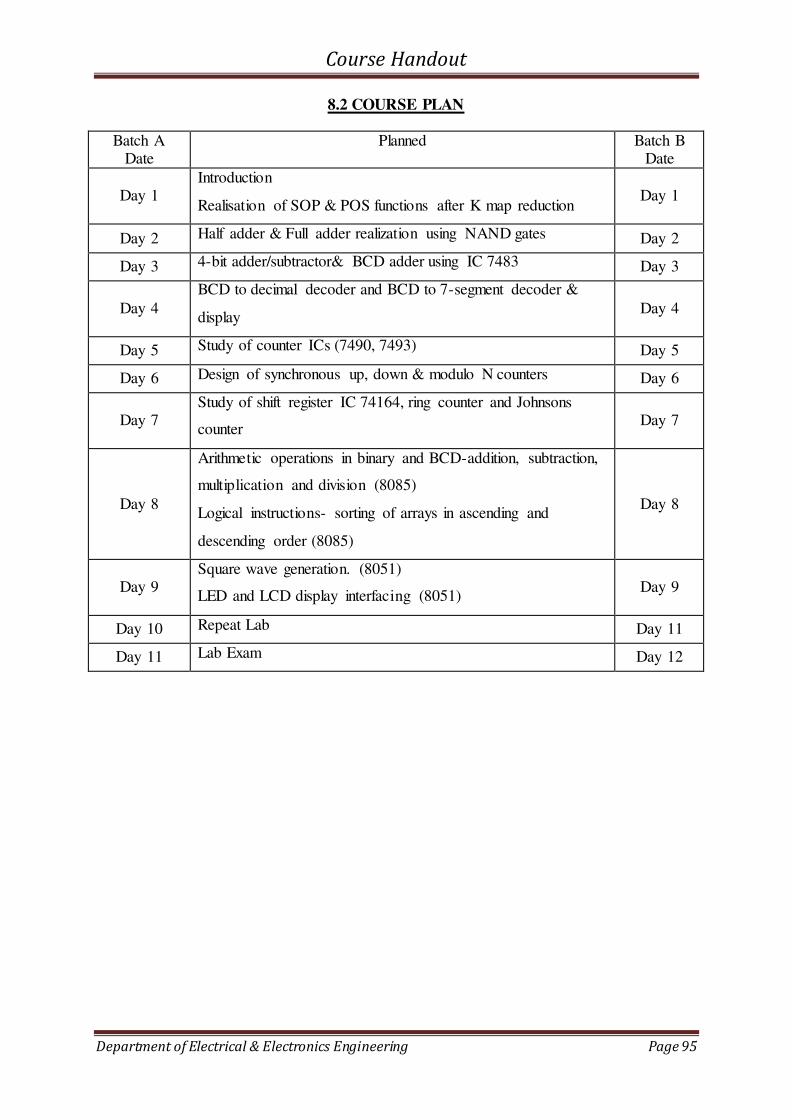
Course Handout
Department of Electrical & Electronics Engineering Page 95
8.2 COURSE PLAN
Batch A Date
Planned Batch B Date
Day 1 Introduction
Realisation of SOP & POS functions after K map reduction Day 1
Day 2 Half adder & Full adder realization using NAND gates Day 2
Day 3 4-bit adder/subtractor& BCD adder using IC 7483 Day 3
Day 4
BCD to decimal decoder and BCD to 7-segment decoder &
display Day 4
Day 5 Study of counter ICs (7490, 7493) Day 5
Day 6 Design of synchronous up, down & modulo N counters Day 6
Day 7 Study of shift register IC 74164, ring counter and Johnsons
counter Day 7
Day 8
Arithmetic operations in binary and BCD-addition, subtraction,
multiplication and division (8085)
Logical instructions- sorting of arrays in ascending and
descending order (8085)
Day 8
Day 9 Square wave generation. (8051)
LED and LCD display interfacing (8051) Day 9
Day 10 Repeat Lab Day 11
Day 11 Lab Exam Day 12

Course Handout
Department of Electrical & Electronics Engineering Page 96
8.3 LAB CYCLE
CYCLE I - DIGITAL CIRCUIT EXPERIMENTS
1. Realisation of SOP & POS functions after K map reduction
2. Half adder & Full adder realization using NAND gates
3. 4-bit adder/subtractor& BCD adder using IC 7483
4. BCD to decimal decoder and BCD to 7-segment decoder & display
5. Study of counter ICs (7490, 7493)
6. Design of synchronous up, down & modulo N counters
7. Study of shift register IC 74164, ring counter and Johnsons counter
CYCLE II - EMBEDDED SYSTEM EXPERIMENTS
8. Arithmetic operations in binary and BCD-addition, subtraction, multiplication and
division (8085)
9. Logical instructions- sorting of arrays in ascending and descending order (8085)
10. Square wave generation. (8051)
11. LED and LCD display interfacing(8051)
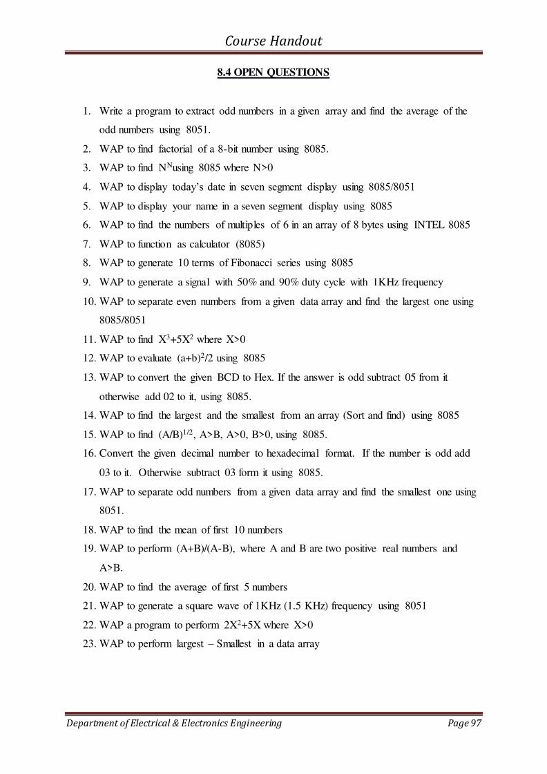
Course Handout
Department of Electrical & Electronics Engineering Page 97
8.4 OPEN QUESTIONS
1. Write a program to extract odd numbers in a given array and find the average of the
odd numbers using 8051.
2. WAP to find factorial of a 8-bit number using 8085.
3. WAP to find NNusing 8085 where N>0
4. WAP to display today’s date in seven segment display using 8085/8051
5. WAP to display your name in a seven segment display using 8085
6. WAP to find the numbers of multiples of 6 in an array of 8 bytes using INTEL 8085
7. WAP to function as calculator (8085)
8. WAP to generate 10 terms of Fibonacci series using 8085
9. WAP to generate a signal with 50% and 90% duty cycle with 1KHz frequency
10. WAP to separate even numbers from a given data array and find the largest one using
8085/8051
11. WAP to find X3+5X2 where X>0
12. WAP to evaluate (a+b)2/2 using 8085
13. WAP to convert the given BCD to Hex. If the answer is odd subtract 05 from it
otherwise add 02 to it, using 8085.
14. WAP to find the largest and the smallest from an array (Sort and find) using 8085
15. WAP to find (A/B)1/2, A>B, A>0, B>0, using 8085.
16. Convert the given decimal number to hexadecimal format. If the number is odd add
03 to it. Otherwise subtract 03 form it using 8085.
17. WAP to separate odd numbers from a given data array and find the smallest one using
8051.
18. WAP to find the mean of first 10 numbers
19. WAP to perform (A+B)/(A-B), where A and B are two positive real numbers and
A>B.
20. WAP to find the average of first 5 numbers
21. WAP to generate a square wave of 1KHz (1.5 KHz) frequency using 8051
22. WAP a program to perform 2X2+5X where X>0
23. WAP to perform largest – Smallest in a data array

Course Handout
Department of Electrical & Electronics Engineering Page 98
8.5 ADVANCED QUESTIONS
1. WAP to take mean of first five odd numbers
2. WAP to take mean of first five even numbers
3. Add two real numbers. If sum is positive, make a LED to glow for 1 second
otherwise make it OFF
4. Interface microprocessor with stepper motor. If the number given is 00 make it to
rotate in clockwise direction. If the number given is FF make it to rotate in CCW
direction
5. Write a program to do down counter from 33, 32,31…..1
6. WAP to find (A*B)1/2, where A and B are positive real numbers and A>B
7. WAP to perform X3+2X2+3X+2
8. WAP to show the output of a Johnson counter using LEDs
9. WAP to show the output of ring counter using LEDs
10. Write a program to find the largest and the smallest numbers of the given data array
and perform (Largest/Smallest)1/2
11. WAP to find the count of odd parity and even parity numbers in a data array and
perform (O+E/O-E) where O- count of odd parity numbers and E-count of even parity
numbers
Course Handout
Department of Electrical & Electronics Engineering Page 99
9. EE333 ELECTRICAL MACHINES LAB II
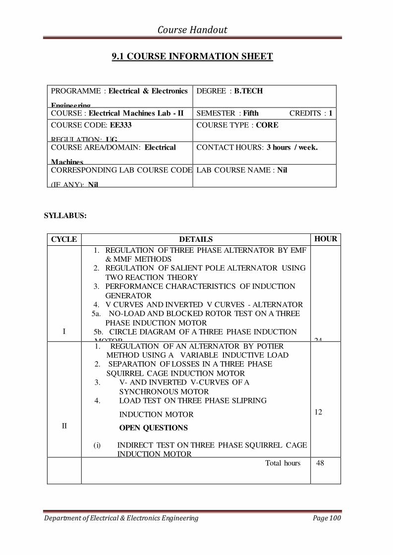
Course Handout
Department of Electrical & Electronics Engineering Page 100
9.1 COURSE INFORMATION SHEET
PROGRAMME : Electrical & Electronics
Engineering
DEGREE : B.TECH
COURSE : Electrical Machines Lab - II SEMESTER : Fifth CREDITS : 1
COURSE CODE: EE333
REGULATION: UG
COURSE TYPE : CORE
COURSE AREA/DOMAIN: Electrical
Machines
CONTACT HOURS: 3 hours / week.
CORRESPONDING LAB COURSE CODE
(IF ANY): Nil
LAB COURSE NAME : Nil
SYLLABUS:
CYCLE DETAILS HOUR
S
I
1. REGULATION OF THREE PHASE ALTERNATOR BY EMF
& MMF METHODS 2. REGULATION OF SALIENT POLE ALTERNATOR USING
TWO REACTION THEORY 3. PERFORMANCE CHARACTERISTICS OF INDUCTION
GENERATOR 4. V CURVES AND INVERTED V CURVES - ALTERNATOR
5a. NO-LOAD AND BLOCKED ROTOR TEST ON A THREE
PHASE INDUCTION MOTOR 5b. CIRCLE DIAGRAM OF A THREE PHASE INDUCTION
MOTOR
24
II
1. REGULATION OF AN ALTERNATOR BY POTIER METHOD USING A VARIABLE INDUCTIVE LOAD
2. SEPARATION OF LOSSES IN A THREE PHASE
SQUIRREL CAGE INDUCTION MOTOR 3. V- AND INVERTED V-CURVES OF A
SYNCHRONOUS MOTOR 4. LOAD TEST ON THREE PHASE SLIPRING
INDUCTION MOTOR
OPEN QUESTIONS
(i) INDIRECT TEST ON THREE PHASE SQUIRREL CAGE INDUCTION MOTOR
12
Total hours 48

Course Handout
Department of Electrical & Electronics Engineering Page 101
TEXT/REFERENCE BOOKS:
T/R BOOK TITLE/AUTHORS/PUBLICATION
T Dr. P. S. Bimbra, Electrical Machinery, Khanna Publishers
T Theraja B. L., A Textbook of Electrical Technology, S. Chand & Company, New
Delhi, 2008.
COURSE PRE-REQUISITES:
C.CODE COURSE NAME DESCRIPTION SEM
EE202
Synchronous and induction
machines
To give exposure to the students about the concepts of alternating current machines, including their constructional details, principle of operation and performance analysis.
S3
BE101-
03
Introduction to Electrical
Engineering
The objective of this course is to set a firm and solid foundation in
Electrical Engineering
To equip the students with strong analytical skills and conceptual
understanding of basic laws and
analysis methods in electrical and in
electrical and magnetic circuits.
S1
COURSE OBJECTIVE
To give hands on experience in testing Alternators, Three phase and Single phase Induction
Motors and Induction generators
COURSE OUTCOMES:
Sl.
No.
DESCRIPTI
ON
Bloom’s Taxonomy Level
1
Students will be able to predict the performance of Induction
machines using standard equivalent circuit models
Application
[Level3]
2
Students will be able to select the appropriate machines based on
the application requirements
Knowledge
[Level 1]
3
Students will be able to illustrate laboratory data and
experimental results using professional quality graphical
representations
Comprehension
[Level 2]
4
Students will work in teams to conduct experiments, analyze
results, and develop technically sound reports of outcomes.
Analysis
[Level 4]

Course Handout
Department of Electrical & Electronics Engineering Page 102
5
Students will be able to identify faults occurring in machines and
take necessary corrective measures
Comprehension
[Level 2]
MAPPING COURSE OUTCOMES (COs) – PROGRAM OUTCOMES (POs) AND
COURSE OUTCOMES (COs) – PROGRAM SPECIFIC OUTCOMES (PSOs)
PO
1
PO
2
PO
3
PO
4
PO
5
PO
6
PO
7
PO
8
PO
9
PO
10
PO
11
PO
12
PSO
1
PSO
2
PSO
3
C 232.1 3 3 3
2
C 232.2 2 3 3 2
C 232.3
2 2
C 232.4
2 3
C 232.5
3 3 3
2
EE232 1 2 2 3 0 0 0 0 1 0 0 0 1 1 0
JUSTIFATIONS FOR CO-PO MAPPING
Mapping L/H/M Justification
C 232.1-
PO1
H Students will be able to apply the knowledge of AC machines to
predict their performance
C 232.1-
PO3
H Students will be able to design system components based on the
performance characteristics of AC machines
C 232.1-
PO4
H Students will be able to provide valid conclusions regarding complex
engineering based on the characteristics of machines
C 232.2-
PO1
M Students can apply the knowledge of basic engineering to select
machines based on the application
C 232.2-
PO2
H Students will be able to analyze the characteristics of various machines
and provide substantiated conclusions
C 232.2-
PO4
H Students will be able to interpret the data the from various experiments
and provide suggestions for different applications
C 232.3- M Student will be able to easily analyze the characteristics of machines
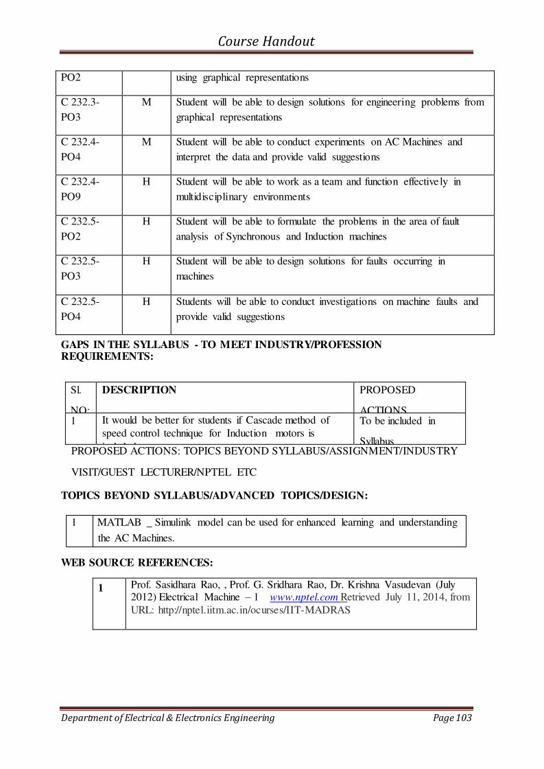
Course Handout
Department of Electrical & Electronics Engineering Page 103
PO2 using graphical representations
C 232.3-
PO3
M Student will be able to design solutions for engineering problems from
graphical representations
C 232.4-
PO4
M Student will be able to conduct experiments on AC Machines and
interpret the data and provide valid suggestions
C 232.4-
PO9
H Student will be able to work as a team and function effectively in
multidisciplinary environments
C 232.5-
PO2
H Student will be able to formulate the problems in the area of fault
analysis of Synchronous and Induction machines
C 232.5-
PO3
H Student will be able to design solutions for faults occurring in
machines
C 232.5-
PO4
H Students will be able to conduct investigations on machine faults and
provide valid suggestions
GAPS IN THE SYLLABUS - TO MEET INDUSTRY/PROFESSION REQUIREMENTS:
Sl.
NO:
DESCRIPTION PROPOSED
ACTIONS 1 It would be better for students if Cascade method of
speed control technique for Induction motors is
included
To be included in
Syllabus PROPOSED ACTIONS: TOPICS BEYOND SYLLABUS/ASSIGNMENT/INDUSTRY
VISIT/GUEST LECTURER/NPTEL ETC
TOPICS BEYOND SYLLABUS/ADVANCED TOPICS/DESIGN:
1 MATLAB _ Simulink model can be used for enhanced learning and understanding
the AC Machines.
WEB SOURCE REFERENCES:
1 Prof. Sasidhara Rao, , Prof. G. Sridhara Rao, Dr. Krishna Vasudevan (July 2012) Electrical Machine – 1 www.nptel.com Retrieved July 11, 2014, from
URL: http://nptel.iitm.ac.in/ocurses/IIT-MADRAS

Course Handout
Department of Electrical & Electronics Engineering Page 104
DELIVERY/INSTRUCTIONAL METHODOLOGIES:
CHALK & TALK STUD. ASSIGNMENT WEB RESOURCES
LCD/SMART
BOARDS STUD. SEMINARS ADD-ON COURSES
ASSESSMENT METHODOLOGIES-DIRECT
ASSIGNMENTS STUD.
SEMINARS
TESTS/MODEL
EXAMS
UNIV.
EXAMINATION STUD. LAB
PRACTICES
STUD. VIVA MINI/MAJOR
PROJECTS
CERTIFICATIONS
ADD-ON COURSES OTHERS
ASSESSMENT METHODOLOGIES-INDIRECT
ASSESSMENT OF COURSE OUTCOMES
(BY FEEDBACK, ONCE)
STUDENT FEEDBACK ON
FACULTY
ASSESSMENT OF MINI/MAJOR
PROJECTS BY EXT. EXPERTS
OTHERS
Prepared By; Approved By;
Mr. Thomas K.P . Dr.Unnikrishnan P.C.
HOD, DEE
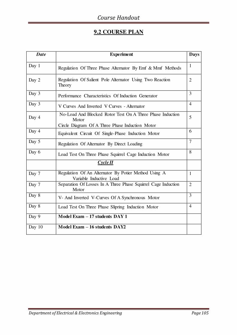
Course Handout
Department of Electrical & Electronics Engineering Page 105
9.2 COURSE PLAN
Date Experiment Days
Day 1 Regulation Of Three Phase Alternator By Emf & Mmf Methods
1
Day 2 Regulation Of Salient Pole Alternator Using Two Reaction Theory
2
Day 3 Performance Characteristics Of Induction Generator
3
Day 3 V Curves And Inverted V Curves - Alternator
4
Day 4 No-Load And Blocked Rotor Test On A Three Phase Induction
Motor
Circle Diagram Of A Three Phase Induction Motor
5
Day 4 Equivalent Circuit Of Single-Phase Induction Motor
6
Day 5 Regulation Of Alternator By Direct Loading
7
Day 6 Load Test On Three Phase Squirrel Cage Induction Motor
8
Cycle II
Day 7 Regulation Of An Alternator By Potier Method Using A
Variable Inductive Load 1
Day 7 Separation Of Losses In A Three Phase Squirrel Cage Induction Motor
2
Day 8 V- And Inverted V-Curves Of A Synchronous Motor
3
Day 8 Load Test On Three Phase Slipring Induction Motor 4
Day 9 Model Exam – 17 students DAY 1
Day 10 Model Exam – 16 students DAY2
Course Handout
Department of Electrical & Electronics Engineering Page 106
9.3 LAB CYCLE
CYCLE I
1. Regulation of Three phase Alternator by MMF & EMF Methods
2. Regulation Of Salient Pole Alternator Using Two Reaction Theory
3. Performance Characteristics Of Induction Generator
4. V Curves And Inverted V Curves - Alternator
5. No-Load And Blocked Rotor Test On A Three Phase Induction Motor
6. Circle Diagram Of A Three Phase Induction Motor
7. Equivalent Circuit Of Single-Phase Induction Motor
CYCLE II
1. Regulation Of An Alternator By Potier Method Using A Variable Inductive Load
2. Separation Of Losses In A Three Phase Squirrel Cage Induction Motor
3. V- And Inverted V-Curves Of A Synchronous Motor
4. Load Test On Three Phase Slipring Induction Motor
Course Handout
Department of Electrical & Electronics Engineering Page 107
9.4 OPEN QUESTIONS
1. Predetermine the % Voltage Regulation of a Non-salient pole alternator at Full load
0.8 pf lag, using Pessimistic method. 2. Predetermine the % Voltage Regulation of a Non-salient pole alternator at Full
load 0.8 pf lead, using pessimistic method. 3. Predetermine the % Voltage Regulation of a Non-salient pole alternator at Full
load u.p.f, using pessimistic method.
4. Predetermine the % Voltage regulation of a Smooth cylindrical alternator at 3/4th Full load 0.866 pf lag, using e.m.f method.
5. Predetermine the % Voltage Regulation of a Smooth cylindrical alternator at 3/4 th Full load 0.866 pf lead, using e.m.f method.
6. Predetermine the % Voltage Regulation of a Smooth cylindrical alternator at 3/4th
Full load u.p.f, using e.m.f method. 7. Conduct a suitable experiment on a given round rotor alternator to determine its
synchronous impedance. Also predetermine the %Voltage Regulation at Full load 0.8 p.f. leading. Draw the phasor diagram.
8. Conduct a suitable experiment on a given round rotor alternator to determine its
synchronous impedance. Also predetermine the %Voltage Regulation at Full load 0.8 p.f. lagging. Draw the phasor diagram.
9. Conduct a suitable experiment on a given round rotor alternator to determine its synchronous impedance. Also predetermine the %Voltage Regulation at Full load u.p.f. Draw the phasor diagram.
10. Predetermine the % Voltage Regulation of a Non-salient pole alternator at 3/4th Full load 0.8 pf lag, using Synchronous Impedance method.
11. Predetermine the % Voltage Regulation of a Non-salient pole alternator at 3/4th Full load 0.8 pf lead, using Synchronous Impedance method.
12. Predetermine the % Voltage Regulation of a Non-salient pole alternator at 3/4th
Full load u.p.f, using Synchronous Impedance method. 13. Predetermine the % Voltage Regulation of a Smooth cylindrical alternator at Full
load 0.866 pf lead, using Optimistic method. 14. Predetermine the % Voltage Regulation of a Smooth cylindrical alternator at Full
load 0.866 pf lag, using Optimistic method.
15. Predetermine the % Voltage Regulation of a Smooth cylindrical alternator at Full load u.p.f, using Optimistic method.
16. Predetermine the % Voltage Regulation of a Non-salient pole alternator at 3/4th Full load 0.8 pf lead, using m.m.f method.
17. Predetermine the % Voltage Regulation of a Non-salient pole alternator at 3/4th
Full load 0.866 pf lead using Optimistic method. 18. Predetermine the % Voltage Regulation of a Non-salient pole alternator at 3/4th
Full load u.p.f, using m.m.f method. 19. Predetermine the % Voltage Regulation of a Smooth cylindrical alternator at Full
load u.p.f using Potier method.
20. Predetermine the % Voltage Regulation of a Smooth cylindrical alternator at 3/4th Full load 0.866 p.f lag, using Potier method.
21. Predetermine the % Voltage Regulation of a Smooth cylindrical alternator at 1.25 times Full load, 0.8 p.f lead, using Potier method.
22. Predetermine the % Voltage Regulation of a Smooth cylindrical alternator at Full
load u.p.f using ZPF method.
Course Handout
Department of Electrical & Electronics Engineering Page 108
23. Predetermine the % Voltage Regulation of a Smooth cylindrical alternator at Full
load 0.8 p.f lag, using ZPF method. 24. Predetermine the % Voltage Regulation of a Smooth cylindrical alternator at Full
load 0.8 p.f lead, using ZPF method. 25. Conduct a proper test on a given round rotor alternator to determine its Potier
reactance.
26. Conduct proper tests on a non-salient pole alternator and determine the field current required to overcome the effect of armature reaction drop at Full load.
27. Predetermine the % Voltage Regulation of a Salient pole alternator at Full load 0.8 p.f lag, using suitable method.
28. Predetermine the % Voltage Regulation of a Salient pole alternator at full load 0.8
p.f lead, using suitable method. 29. Predetermine the % Voltage Regulation of a Salient pole alternator at full load
u.p.f, using suitable method. 30. Predetermine the % Voltage Regulation of a Salient pole alternator at Full load 0.8
p.f lag, using Blondel’s method.
31. Predetermine the % Voltage Regulation of a Salient pole alternator at full load 0.8 p.f lead, using Blondel’s method.
32. Predetermine the % Voltage Regulation of a Salient pole alternator at full load u.p.f, using Blondel’s method.
33. Predetermine the % Voltage Regulation of a Salient pole alternator at Full load 0.8
p.f lag, using Slip test. 34. Predetermine the % Voltage Regulation of a Salient pole alternator at full load 0.8
p.f lead, using Slip test. 35. Predetermine the % Voltage Regulation of a Salient pole alternator at full load
u.p.f, using Slip test.
36. For a given A.C. Machine, determine the reactances due to the effect of saliency of the rotor by conducting suitable tests.
37. Conduct suitable experiments on a Salient pole alternator to determine its synchronous reactances.
38. Plot the performance characteristics (η Vs O/P, p.f Vs O/P & % slip Vs O/P) of the given Induction Generator.
39. Plot the performance characteristics (η Vs O/P, p.f Vs O/P & % slip Vs O/P) of the given Induction Machine when the same is operated at super synchronous speed.
40. Run the given 3 φ Induction machine at a hyper synchronous speed and determine the efficiency and p.f. at a particular load current (5A).
41. Run the given 3 φ Induction machine at a leading p.f. operation and determine the slips at a load current of 5 A.
42. Conduct a proper test on a given 3 φ Induction machine, allowing it to run with a negative slip and determine the p.f. and efficiency at any two load currents.
43. Plot the V curve & Inverted V curve of the given alternator at an output of 1800W.
44. Plot the V curve & Inverted V curve of the given alternator at no-load. 45. Plot the variation of armature current with field current of the given alternator at an
output of 1800W 46. Plot the variation of p.f. with field current of the given 3 φ alternator at an output
of 1800W.
47. Plot the variation of armature current with field current of the given 3 φ alternator at no-load condition.
48. Plot the variation of p.f. with field current of the given 3 φ alternator at no-load condition.

Course Handout
Department of Electrical & Electronics Engineering Page 109
49. Plot the p.f. Vs If characteristics of the given 3 φ Synchronous Motor at an output load of 2160 W.
50. Plot the V-Curve of the given 3 φ Synchronous Motor at No-load.
51. Plot the Inverted V-Curve of the given 3 φ Synchronous Motor at an output load of 2160W
52. Plot the Armature current Vs If characteristics of the given 3 φ Synchronous Motor at No-load.
53. Plot the Armature current Vs field current characteristics of the given 3 φ Synchronous Motor at a power output of 2160W.
54. Plot the p.f. Vs field current characteristics of the given 3 φ Synchronous Motor at a power output of 2160W.
55. Draw the exact equivalent circuit of the given 3φ Induction motor by conducting suitable tests.
56. Determine the total resistance & leakage reactance per phase of the given 3φ Squirrel Cage Induction motor referred to stator by conducting suitable test.
57. By conducting suitable tests, determine the Power input to the Rotor, Efficiency
and Torque developed at a slip of 0.04 of the given 3φ Squirrel Cage Induction motor.
58. By conducting suitable tests, draw the circle diagram of the given 3 φ Induction motor & obtain the maximum power output.
59. For a given 3 φ Induction motor, pre-determine the maximum power output by
conducting proper tests. 60. Conduct proper tests on a 3 φ Induction motor and determine the input p.f. at a slip
of 4% using exact equivalent circuit. 61. Conduct suitable tests on a 3 φ Induction motor and obtain maximum torque that
the motor can develop.
62. Conduct suitable tests on a 3 φ Induction motor and obtain maximum power output that the motor can develop.
63. By conducting suitable tests, draw the circle diagram of the given 3 φ Induction motor & obtain the maximum torque.
64. By conducting suitable tests, draw the circle diagram of the given 3 φ Induction motor & obtain the stator current at full load power.
65. By conducting suitable tests, draw the circle diagram of the given 3 φ Induction motor & obtain the efficiency at full load condition.
66. By conducting suitable tests, draw the circle diagram of the given 3 φ Induction motor & obtain the slip at full load condition.
67. Determine equivalent resistance and reactance of a given 3 φ Induction motor. Also construct the circle diagram.
68. Draw the equivalent circuit of the given 1 φ Induction motor based on double field revolving theory by conducting suitable tests.
69. For the given 1 φ Induction motor, determine the rotor circuit resistance with
respect to the forward and backward rotating fields. 70. For the given 1 φ Induction motor, determine the equivalent resistance and
reactance with respect to the forward and backward rotating fields. 71. Conduct proper test on the given 3-phase Alternator and determine its Voltage
regulation at Full load, u.p.f.
72. Conduct proper test on the given 3-phase Alternator and plot the % Voltage regulation Vs power output. Load may be taken as a resistive load.

Course Handout
Department of Electrical & Electronics Engineering Page 110
73. Conduct a load test on a three phase squirrel cage induction motor to obtain the
following performance characteristics: Torque vs Output, Efficiency vs Output, Input current vs Output, p.f. vs Output and slip vs Output.
74. Conduct a load test on a three phase Conduct proper test on the given 3-phase Alternator and plot the % Voltage regulation Vs power output. Load may be taken as a resistive load.
75. Conduct a load test on a three phase squirrel cage induction motor and obtain the Input current, p.f. and slip at half full load.
76. Conduct a load test on a three phase squirrel cage induction motor and obtain the Torque and Efficiency at full load.
77. Conduct a load test on a three phase Slip Ring induction motor and obtain the Input
current, p.f. and slip at 11 A load. 78. Conduct a load test on a three phase Slip Ring induction motor and obtain the
Torque and Efficiency at 11.5 A load. 79. Separate the constant loss of a given three phase squirrel cage induction motor into
its components at rated voltage. ie. Iron Loss & Mechanical Loss.

Course Handout
Department of Electrical & Electronics Engineering Page 111
9.5 ADVANCED QUESTIONS
1. Voltage Regulation Of An Alternator By Feeding Back To Mains
2. Cascade Operation Of Induction Motor
Course Handout
Department of Electrical & Electronics Engineering Page 112
10. EE341 DESIGN PROJECT

Course Handout
Department of Electrical & Electronics Engineering Page 113
10.1 COURSE INFORMATION SHEET
PROGRAMME: ELECTRICAL AND
ELECTRONICS ENGINEERING DEGREE: BTECH
COURSE: DESIGN Project SEMESTER: S5 CREDITS: 2
COURSE CODE: EE341
REGULATION: 2017
COURSE TYPE: CORE
COURSE AREA/DOMAIN: ENGINEERING (All
Branches)
CONTACT HOURS: 1 (Tut ) + 2(PRACTICAL)
HOUR/WEEK
CORRESPONDING LAB COURSE CODE (IF
ANY): NIL LAB COURSE NAME: NIL
SYLLABUS:
MO
DUL
E
CONTENTS HOURS
SEM.
EXAM
MARKS
I
(Study)
Study : Take minimum three simple products, processes or
techniques in the area of specialisation, study, analyse and present them. The analysis shall be focused on functionality, strength, material, manufacture/construction, quality, reliability, aesthetics,
ergonomics, safety, maintenance, handling, sustainability, cost etc. whichever are applicable. Each student in the group has to present
individually; choosing different products, processes or techniques.
L10 50%
II
(De
sign)
The project team shall identify an innovative product, process or technology and proceed with detailed design. At the end, the team
has to document it properly and present and defend it. The design is expected to concentrate on functionality, design for
strength is not expected.
L30 50%
TEXT/REFERENCE BOOKS:
T/R
T1
Balmer, R. T., Keat, W. D., Wise, G., and Kosky, P., Exploring Engineering, Third Edition: An Introduction to Engineering and Design - [Part 3 - Chapters 17 to 27], ISBN-13: 978-0124158917 ISBN-10: 0124158919
T2 Dym, C. L., Little, P. and Orwin, E. J., Engineering Design - A Project based introduction - Wiley, ISBN-978-1-118-32458-5
T3 Eastman, C. M. (Ed.), Design for X Concurrent engineering imperatives, 1996, XI, 489 p. ISBN 978-94-011-3985-4 Springer
T4 Haik, Y. And Shahin, M. T., Engineering Design Process, Cengage Learning, ISBN-13: 978-0-495-66816-9

Course Handout
Department of Electrical & Electronics Engineering Page 114
T5 Pahl, G., Beitz, W., Feldhusen, J. and Grote, K. H., Engineering Design: A Systematic
T6 Pahl, G., Beitz, W., Feldhusen, J. and Grote, K. H., Engineering Design: A Systematic
Approach, 3rd ed. 2007, XXI, 617p., ISBN 978-1-84628-319-2
T7 Voland, G., Engineering by Design, ISBN 978-93-325-3505-3, Pearson India
R1 Michael Luchs, Scott Swan, Abbie Griffin, 2015. Design Thinking. 405 pages, John Wiley & Sons, Inc
R2 E-Book: http://opim.wharton.upenn.edu/~ulrich/designbook.html
COURSE PRE-REQUISITES:
C.CODE COURSE NAME DESCRIPTION SEM
BE102 Design Engineering Design Thinking Process S2
COURSE OBJECTIVES:
1 To understand the engineering aspects of design with reference to simple products
2 To foster innovation in design of products, processes or systems
3 To develop design that add value to products and solve technical problems
COURSE OUTCOMES:
Sl. NO DESCRIPTION
Blooms’ Taxomomy
Level
C341.1 Think innovatively on the development of components, products, processes
or technologies in the engineering field.
Level 1,
Level 3,
Level 4
C341.2 Analyse the problem requirements and arrive workable design solutions.
Level 1
Level 2
Level 4
C341.3
Ability to think of different solution to a given problem, compare different
solutions and to determine the optimum design solution among them
Level 2
Level 3
Level 6
C341.4
Has the course made you to observe and analyse the different designs
around you in your daily life and made you to think creatively
Level 1
Level 4
Level 6

Course Handout
Department of Electrical & Electronics Engineering Page 115
C341.5
Have you identified and prioritized the different features (expected, normal
and exciting) that needs to be chosen while designing a product.
Level 1
Level 4
Level 6
C341.6
Has the course Design and Engineering developed your ability to adapt to
different groups and to propose your ideas to the success of the group?
Level 6
CO-PO AND CO-PSO MAPPING
PO
1
PO
2
PO
3
PO
4
PO
5
PO
6
PO
7
PO
8
PO
9
PO
10
PO
11
PO
12
PSO
1
PSO
2
PSO
3
C341.1 - - - - - - - - 3 2 3 - - - -
C341.2 - 3 - - - - - - - - - 2 - - -
C341.3 3 3 2 2 - - - - - - - 2 - - -
C341.4 2 - - 1 - 1 - - - - - 3 - - 2
C341.5 - 1 3 - - - - - - - - - - - -
C341.6 - - - - - - - 3 3 3 3 - - -
1- Low correlation (Low), 2- Medium correlation(Medium) , 3-High correlation(High)
JUSTIFATIONS FOR CO-PO MAPPING
MAPPING LOW/MEDIUM/HIG
H
JUSTIFICATION
C341.1 – PO9 H Students should use the knowledge to develop solutions for problems
C341.1 - PO10 M Students could use the knowledge to for implementation of their Ideas
C341.1– PO11 H Students need to Identify the problem to solve it
C341.2 – PO2 H Need to analyze different solutions to a problem
C341.2 – PO12 M Review/ Research is required to identify different features
C341.3-PO1 H To Find the optimum solution
C341.3-PO2 H To provide features to a product after considering all aspects
C341.3-PO3 M To think of different solutions
C341.3-PO4 M Creative thoughts
C341.3-PO12 M To observe the need of the society
C341.4-PO1 M Increase the ability to work in a team
C341.4-PO4 L Increase the ability to work in a team
C341.4-PO6 L Increased the communication within the group
C341.4-PO12 H Increased the communication within the group
C341.5-PO2 L Skills to lead a team
C341.5-PO3 H Skills to lead a team
C341.6-PO9 H Skills to identify the need
C341.6-PO10 H Identify different solutions to a problem
C341.6-PO11 H Increase observational skills

Course Handout
Department of Electrical & Electronics Engineering Page 116
C341.6-PO12 H Increase the ability to work in a team
JUSTIFATIONS FOR CO-PSO MAPPING
GAPS IN THE SYLLABUS - TO MEET INDUSTRY/PROFESSION REQUIREMENTS:
SI
NO DESCRIPTION
PROPOSED
ACTIONS
RELEVANCE
WITH POs
RELEVANCE
WITH PSOs
1 Market survey
Activity to prepare
questionnaire on
market survey, HOQ
1, 6 2
WEB SOURCE REFERENCES:
1 E-Book: http://opim.wharton.upenn.edu/~ulrich/designbook.html
2 http://www2.warwick.ac.uk/fac/sci/wmg/ftmsc/modules/modulelist/peuss /designforx/design_for_x_notes
DELIVERY/INSTRUCTIONAL METHODOLOGIES:
☐ CHALK & TALK ☐ STUD. ASSIGNMENT ☐ WEB RESOURCES
☐ LCD/SMART BOARDS ☐ STUD. SEMINARS ☐ ADD-ON COURSES
ASSESSMENT METHODOLOGIES-DIRECT
☐ ASSIGNMENTS √ ☐ STUD. SEMINARS √ ☐ TESTS/MO DEL
EXAMS√ ☐ UNIV. EXAMINATIO N√
☐ STUD. LAB PRACTICES√ ☐ STUD. VIVA√ ☐ MINI/MAJOR
PROJECTS√ ☐ CERTIFICATIONS√
☐ ADD-ON COURSES√ ☐ OTHERS (Skill
Development) √
ASSESSMENT METHODOLOGIES-INDIRECT
☐ ASSESSMENT OF COURSE OUTCOMES (BY FEEDBACK,
ONCE) ☐ STUDENT FEEDBACK O N FACULTY (TWICE)
☐ ASSESSMENT OF MINI/MAJOR PROJECTS BY EXT.
EXPERTS ☐ OTHERS
Prepared by Approved by
Mr.Unnikrishnan L Dr. Unnikrishnan P.C.
(Faculty) (HOD)
MAPPING LOW/MEDIUM/HIGH JUSTIFICATION
C341.4-PSO3 M Continued Learning
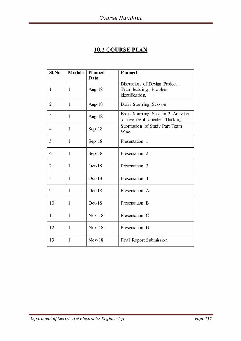
Course Handout
Department of Electrical & Electronics Engineering Page 117
10.2 COURSE PLAN
Sl.No Module Planned Date
Planned
1 1 Aug-18 Discussion of Design Project , Team building, Problem
identification.
2 1 Aug-18 Brain Storming Session 1
3 1 Aug-18 Brain Storming Session 2, Activities
to have result oriented Thinking.
4 1 Sep-18 Submission of Study Part Team Wise.
5 1 Sep-18 Presentation 1
6 1 Sep-18 Presentation 2
7 1 Oct-18 Presentation 3
8 1 Oct-18 Presentation 4
9 1 Oct-18 Presentation A
10 1 Oct-18 Presentation B
11 1 Nov-18 Presentation C
12 1 Nov-18 Presentation D
13 1 Nov-18 Final Report Submission