Counter-Flow Centrifugal Chillers with Two-Stage ...
85
WCT Counter-Flow Centrifugal Chillers with Two-Stage Compressors 2200 to 3250 TONS (7750 to 11400 kW) Series Counter-Flow with Two-Stage Compressors 4500 to 6400 TONS (15830 to 22500 kW) Operating & Maintenance Manual D-EOMWC01302-16EN
Transcript of Counter-Flow Centrifugal Chillers with Two-Stage ...

WCT
Counter-Flow Centrifugal Chillers with Two-Stage Compressors
2200 to 3250 TONS (7750 to 11400 kW)
Series Counter-Flow with Two-Stage Compressors
4500 to 6400 TONS (15830 to 22500 kW)
Operating & Maintenance Manual
D-EOMWC01302-16EN
OMM WCT Centrifugal Chillers D-EOMWC01302-16EN - 2/84
Table of Contents Safety Instructions ........................................................................................... 3 Introduction ..................................................................................................... 4 Components and Operation ............................................................................ 6
Lubrication System .............................................................................................................. 9 Motor Cooling .................................................................................................................... 10
Features of the Control Panel ....................................................................... 13 Controller Description ........................................................................................................ 15 Hardware Structure ............................................................................................................ 15 System Architecture ........................................................................................................... 16 Field Wiring Diagram ........................................................................................................ 17
Operator Interface Touch Screen (OITS) ................................................... 19 Navigation .......................................................................................................................... 20 Screen Descriptions ............................................................................................................ 24 Main Screens ...................................................................................................................... 24 SET Screens ....................................................................................................................... 29 Interface Screen .................................................................................................................. 43 Trend Screens ..................................................................................................................... 44 Clearing Alarms ................................................................................................................. 46
Using the Controller ...................................................................................... 49 Navigating .......................................................................................................................... 50 Setpoints ............................................................................................................................. 57
Condenser Water ........................................................................................... 62
Maintenance ................................................................................................... 64 Routine Maintenance ......................................................................................................... 64 Equipment Cleaning and Preserving .................................................................................. 69 Annual Startup ................................................................................................................... 71 Repair of System ................................................................................................................ 72 Charging the System .......................................................................................................... 74
Maintenance Schedule ................................................................................... 77
PERATING LOG SHEET ............................................................................ 81 Service Programs ........................................................................................... 82 Operator Schools ........................................................................................... 82
Warranty Statement ...................................................................................... 82
Manufactured in an ISO Certified Facility
©2013 Daikin International. Illustrations and data cover the Daikin International product at the time of publication and we reserve the right to make changes in design and construction at anytime without notice. ™® The following are trademarks or registered trademarks of their respective companies: BACnet from ASHRAE; LONMARK, LonTalk, LONWORKS, and the LONMARK logo are managed, granted and used by LONMARK International under a license granted by Echelon Corporation; Modbus from Schneider Electric; MicroTech III, and Open Choices from Daikin International.

OMM WCT Centrifugal Chillers D-EOMWC01302-16EN - 3/84
Safety Instructions
The following recommendations should be carefully observed as part of installation, operation, maintenance or
service.
This equipment must be installed and operated by trained and qualified personnel who have received
suitable instruction in their use.
This manual is intended for use by owner or Daikin authorized service personnel.
Cautions and Warnings At several points in the manual, items of special interest or significant impact are highlighted by one of the
following notices in the appropriate section of the manual.
DANGER
Dangers indicate a hazardous situation which will result in death or serious injury if not avoided.
WARNING
Warnings indicate potentially hazardous situations, which can result in property damage, severe personal injury, or death if not avoided.
CAUTION
Cautions indicate potentially hazardous situations, which can result in personal injury or equipment damage if not avoided.
!
!
!
OMM WCT Centrifugal Chillers D-EOMWC01302-16EN - 4/84
Introduction
CAUTION
It is important that the operator reads this manual to become familiar with the equipment before attempting to operate the chiller..
NOTE
During the initial startup of the chiller the Daikin technician will be available to answer any questions and instruct in the proper operating procedures.
This Daikin centrifugal chiller represents a substantial investment and deserves the attention and care normally given to keep this equipment in good working order. If abnormal or unusual operating conditions occur, it is recommended that a Daikin service technician be consulted.
General Description
The Daikin Two-Stage Dual Centrifugal Water Chillers (WCT) are complete, self-contained,
automatically controlled fluid chilling units. Each unit is completely assembled and factory tested
before shipment. These chillers have a separate refrigerant circuit for each compressor. They are
available in single pass arrangement only. They provide the high full load efficiency advantage of
two separate chillers arranged for counterflow operation in a single, compact unit.
The Daikin Model WCT Chillers use 2-stage K compressors and provide cooling capacity from
2200 to 3250 TONS (7750 to 11400 kW) depending on operating conditions in each chiller,
which comes up 4500 to 6400 TONS (15830 to 22500 kW) system capacity when chiller installs
in series counter-flow configuration. In the WCT series, each unit has two compressors and two
economizers connected to a single condenser, and an evaporator. Each condenser and evaporator
has two separate refrigerant circuits. WCT chiller is suitably designed for series counter-flow,
which two WCT unit is connecting in series and work as one chiller.
The driveline of the WCT is made up of two two-stage compressors, each with a gear set and a 2-
pole, induction semi-hermetic motor.
The controls are pre-wired, adjusted and tested. Only normal field connections such as water and
relief valve piping, electrical and interlocks, etc. are required, thereby simplifying installation and
increasing reliability. Most of the necessary equipment protection and operating controls are factory
installed in the control panel.
All Daikin centrifugal chillers must be commissioned at the job site by a factory trained Daikin
authorized technician.
The standard limited warranty on this equipment covers parts that prove defective in material or
workmanship. Specific details of this warranty can be found in the warranty statement furnished
with the equipment.
!
!
OMM WCT Centrifugal Chillers D-EOMWC01302-16EN - 5/84
Nomenclature
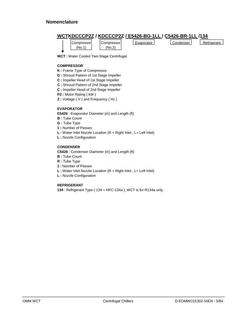
WCTKDCCCP2Z / KDCCCP2Z / E5426-BG-1LL / C5426-BR-1LL /134
WCT : Water Cooled Two-Stage Centrifugal
COMPRESSOR
K : Frame Type of Compressor
D : Shroud Pattern of 1st Stage Impeller
C : Impeller Head of 1st Stage Impeller
C : Shroud Pattern of 2nd Stage Impeller
C : Impeller Head of 2nd Stage Impeller
P2 : Motor Rating ( kW )
Z : Voltage ( V ) and Frequency ( Hz )
EVAPORATOR
E5426 : Evaporator Diameter (in) and Length (ft)
B : Tube Count
G : Tube Type
1 : Number of Passes
L : Water Inlet Nozzle Location (R = Right Inlet ; L= Left Inlet)
L : Nozzle Configuration
CONDENSER C5426 : Condenser Diameter (in) and Length (ft)
B : Tube Count
R : Tube Type
1 : Number of Passes
L : Water Inlet Nozzle Location (R = Right Inlet ; L= Left Inlet)
L : Nozzle Configuration
REFRIGERANT
134 : Refrigerant Type ( 134 = HFC-134a ); WCT is for R134a only.
Compressor
(No.1)
Evaporator Compressor
(No.2)
Condenser Refrigerant

OMM WCT Centrifugal Chillers D-EOMWC01302-16EN - 6/84
Components and Operation
Figure 1, WCT Major Component Locations
Note: Evaporator nozzles may be side-by-side or over-and-under depending on model.
Dual Circuit, Series Counter-flow Chillers Overview The WCT chiller has a single evaporator and a condenser. Each evaporator and condenser shell
contains two separate refrigerant circuits for each of the two compressors and economizers on the
chiller. Each circuit is isolated from each other by a welded tube sheet in the middle of the vessel.
They are available in single pass only. Single-pass water flows in evaporator and condenser are
counterflow to each other.
Each of the two separate refrigerant circuits use the vapor compression cycle as shown in Figure 3.
. Figure 2, Series Counterflow Flow Diagram
ECONOMIZER
Circuit 2
CONTROL BOX CONDENSER
Circuit 2 UNIT MONITOR EVAPORATOR
Circuit 2
ECONOMIZER
Circuit 1
EVAPORATOR
Circuit 1
COMPRESSOR
Circuit 1
CONDENSER
Circuit 1
COMPRESSOR
Circuit 2
OMM WCT Centrifugal Chillers D-EOMWC01302-16EN - 7/84
,
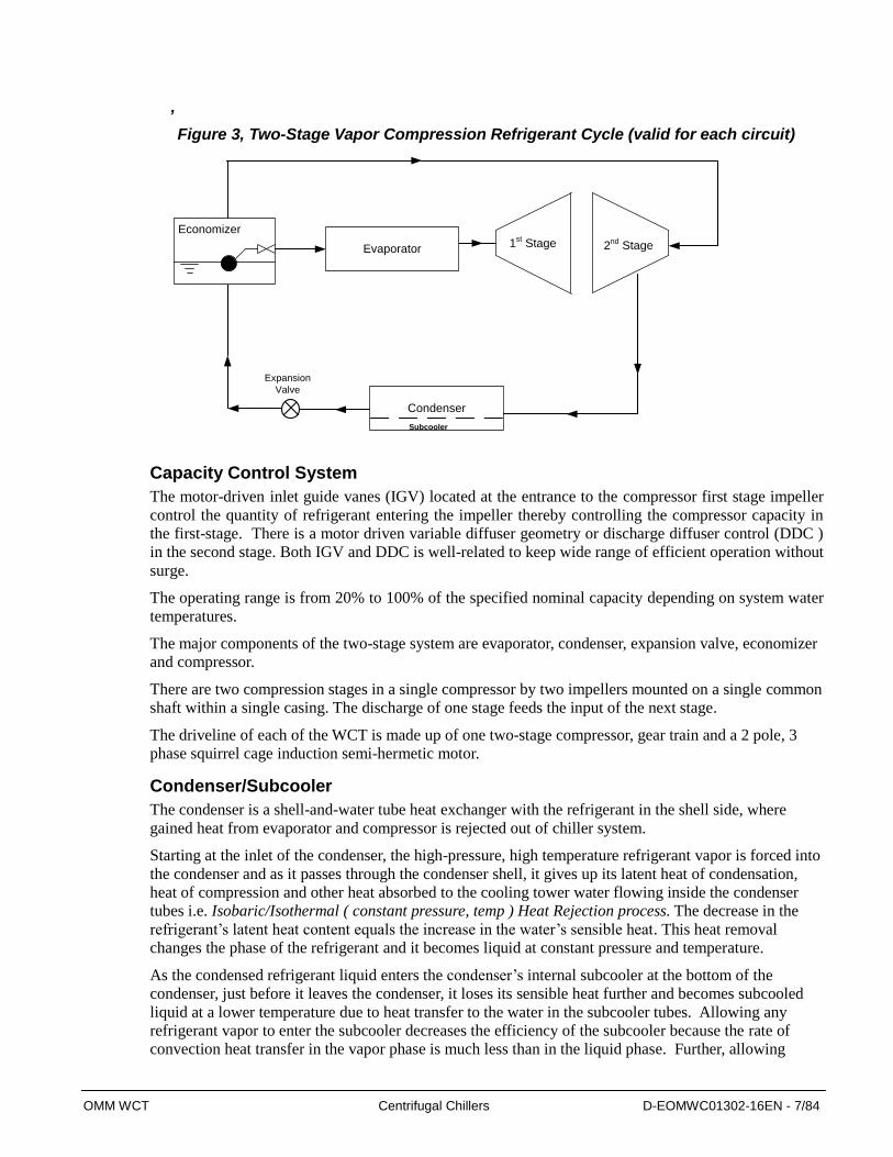
Figure 3, Two-Stage Vapor Compression Refrigerant Cycle (valid for each circuit)
2nd
Stage
Expansion
Valve
Condenser
1st StageEvaporator
Economizer
Subcooler
Capacity Control System
The motor-driven inlet guide vanes (IGV) located at the entrance to the compressor first stage impeller
control the quantity of refrigerant entering the impeller thereby controlling the compressor capacity in
the first-stage. There is a motor driven variable diffuser geometry or discharge diffuser control (DDC )
in the second stage. Both IGV and DDC is well-related to keep wide range of efficient operation without
surge.
The operating range is from 20% to 100% of the specified nominal capacity depending on system water
temperatures.
The major components of the two-stage system are evaporator, condenser, expansion valve, economizer
and compressor.
There are two compression stages in a single compressor by two impellers mounted on a single common
shaft within a single casing. The discharge of one stage feeds the input of the next stage.
The driveline of each of the WCT is made up of one two-stage compressor, gear train and a 2 pole, 3
phase squirrel cage induction semi-hermetic motor.
Condenser/Subcooler
The condenser is a shell-and-water tube heat exchanger with the refrigerant in the shell side, where
gained heat from evaporator and compressor is rejected out of chiller system.
Starting at the inlet of the condenser, the high-pressure, high temperature refrigerant vapor is forced into
the condenser and as it passes through the condenser shell, it gives up its latent heat of condensation,
heat of compression and other heat absorbed to the cooling tower water flowing inside the condenser
tubes i.e. Isobaric/Isothermal ( constant pressure, temp ) Heat Rejection process. The decrease in the
refrigerant’s latent heat content equals the increase in the water’s sensible heat. This heat removal
changes the phase of the refrigerant and it becomes liquid at constant pressure and temperature.
As the condensed refrigerant liquid enters the condenser’s internal subcooler at the bottom of the
condenser, just before it leaves the condenser, it loses its sensible heat further and becomes subcooled
liquid at a lower temperature due to heat transfer to the water in the subcooler tubes. Allowing any
refrigerant vapor to enter the subcooler decreases the efficiency of the subcooler because the rate of
convection heat transfer in the vapor phase is much less than in the liquid phase. Further, allowing
OMM WCT Centrifugal Chillers D-EOMWC01302-16EN - 8/84
vapor to enter the subcooler may allow vapor to leave the condenser, thereby decreasing the efficiency
of the system. Therefore, the liquid level must extend far enough above the subcooler entrance to
prevent vapor within vortex, which is typically formed at high flow rates, from entering the subcooler.
When the chiller is operating at load, the most reliable source of liquid refrigerant is the condenser.
Liquid refrigerant in the evaporator will be boiling.
Expansion Valve
The liquid refrigerant travels through the liquid line to the expansion valve where the pressure is
reduced and part of the refrigerant flashes into vapor creating of a two-phase refrigerant mixture
downstream of the expansion valve. The vapor absorbs the liquid’s latent heat of vaporization and
lowers the liquid temperature flowing to the economizer. Therefore, the net latent heat content of the
refrigerant is unchanged or no heat loss to the outside due to this heat exchange between the liquid and
vapor.
This is the first expansion process in the two-stage cycle. Since the decrease in the refrigerant liquid’s
sensible heat content equals the increase in the refrigerant vapor’s latent heat of vaporization, the total
enthalpies before and after expansion are the same. This part of the refrigeration cycle is called the
Isenthalpic – constant enthalpy Expansion process.
Economizer and Two-stage Compressor
An economizer is a flash tank consisting of baffles to separate the refrigerant vapor from liquid and
mechanical float-type expansion valve(s) for liquid control. Economizer separates any vapor, mainly
generated at primary expansion valve, and preventing such vapor feed it into evaporator. Vapor in the
economizer may no longer work for cooling water in the evaporator, but 1st compression stage of
compressor must work for the vapor once it is provided into evaporator which cause loss of
compression power. Thus economizer promises efficient chiller operation than without economizer
system, which is one of the most advantage of 2-stage with economizer system.
The expanded liquid-vapor mixture from the expansion valve enters the economizer where vapor and
liquid separate from each other.
The liquid, being denser than the vapor, accumulates at the bottom of the economizer and the vapor
bubbles through liquid refrigerant to the top of the economizer. As the second stage impeller of the
compressor exerts suction and draws vapor from the economizer, it reduces the pressure of the
economizer. As the pressure is lowered, so is the temperature or boiling point of the refrigerant in the
economizer to a temperature corresponding to the suction pressure of the second stage. This vapor is
piped to the inlet of the second stage impeller, thereby maintaining the economizer at interstage
pressure.
As the liquid level rises, it lifts the float valve and opens it. The liquid exiting the float valve opening
expands second time and its pressure drops further and more latent heat is absorbed by the vapor from
liquid – a zero heat loss from the refrigerant to the ambient, and lowers the refrigerant liquid’s
temperature further flowing into the evaporator.
Because of this additional refrigerant liquid temperature drop, there will not be a capacity penalty to the
chiller even though the mass flow of the refrigerant is less than a single-cycle system compared with the
same capacity. The shrinkage of refrigerant mass, on the other hand is, due to the refrigerant vapor
separating in the economizer and leaving the economizer to the inlet of the second stage suction of the
compressor where it mixes with and desuperheats the discharge vapor from the first stage impeller. The
two incoming refrigerant vapor streams mix together in the interstage elbow before flowing into the
second stage compression ( Isentropic ( constant entropy ) compression process ).
As the economizer vapor decreases the temperature of the first stage discharge vapor entering the
second stage, it reduces the required compression energy input by utilizing energy that would otherwise
be wasted which gives an efficiency advantage to the two-stage over single-stage.

OMM WCT Centrifugal Chillers D-EOMWC01302-16EN - 9/84
The terms “intercooler” and “economizer” are interchangeably used in the industry for the liquid/vapor
separator tank.
Evaporator
The evaporator is a flooded shell-and-water tube heat exchanger with refrigerant on the shell side, where
chilled water getting cooler, eventually to desired target temp level at water outlet of the evaporator.
When the compressor starts, it creates suction and draws some of the refrigerant gas from the
evaporator, thus decreasing the pressure of the evaporator. As the refrigerant pressure is lowered, so is
the temperature or boiling point of the refrigerant in the evaporator, and it is this factor that creates a
difference in temp between the refrigerant and the water which is to be cooled. Thus, a flow of heat from
the warmer water to the refrigerant is set up.
The refrigerant enters the evaporator at or near the bottom of the shell with vapor quality in the range of
0 to 30 %. In order to boil the greatest possible amount of refrigerant in the evaporator, it is necessary
that the entire surface of the evaporator be kept wet with refrigerant liquid. Under this condition of
operation the refrigerant vapor from the vaporized liquid leaves the evaporator outlet in a saturated
condition, which means it is the same temperature as the liquid in the evaporator (Isobaric/Isothermal (
constant pressure, temp ) heat addition process ). The warm water to be chilled from the cooling load
circulating through the evaporator tubes causes the pool of liquid refrigerant to boil and for a horizontal
tube arrangement, the refrigerant then flows upward throughout the tube bundle, changing phase and
emerging from the top tube row at or near a vapor quality of 100 %. This boiling displaces the liquid
level upwards until the entire bundle is just submerged in boiling refrigerant. The increased boiling
takes place where the tube depth is greater in the bundle at the center. The greater the tube depth, the
greater the amount of heat transferred causing boiling.
The flow is then directed out of the evaporator shell and routed to the inlet of the compressor. Any
major entrained liquid in the vapor flow stream can fall back to the evaporator tube bundle by gravity
and may not be carried over to the compressor suction, which keeps compressor performance/reliability
staying longer.
As the load across the evaporator increases the available refrigerant will boil off more rapidly, if it is
completely evaporated prior to exiting the evaporator, the vapor itself will continue to absorb heat. This
heat is referred to as superheat which is the heat added to a substance above its saturation temperature
itself will continue to absorb heat.
The vaporized refrigerant, that is, the “suction gas,” is compressed by the first stage of the compressor
to the second stage to complete the cycle.
Lubrication System
The lubrication system provides lubrication and heat removal for compressor bearings and internal
parts. Lubricant must be visible in the oil sump sight glass at all times and must be added during the
operation for any oil loss.
Emkarate RL68H Polyolester Oil must be used in the two-stage centrifugal compressor. The nominal
oil charge for K compressor is 22 gallons.
The internal oil sump for the compressor is completely self-contained within the compressor housing.
The assembly includes a motor driven submersible 1 HP, 4 pole oil pump (220 V,3 phase, 50/60 Hz), a
1000 Watt (220 V,1 phase, 50/60 Hz) cartridge type immersion oil heater and a 10 micron oil filter.
During normal chiller operation, the unit control center operates and controls the oil pump at all times.
The oil heater is only energized during compressor is off. The oil pump operates prior to compressor
OMM WCT Centrifugal Chillers D-EOMWC01302-16EN - 10/84
run (prelube) to provide oil to the bearings. It also runs after compressor shutdown to lubricate the
bearings during coast down (postlube).
During idle periods, the oil in the sump tends to absorb as much refrigerant as it can hold, depending
upon the oil temperature and sump pressure. Lower oil temperature will increase of amount of
refrigerant absorbed that can cause violent foaming during compressor start-up, as the system pressure is
lowered. Refrigerant bubbles out of the oil during that time and the subsequent foaming can affect the
oil pump operation and system oil differential pressure.
The oil is pumped to the internal oil filter in the compressor casting and then to the external refrigerant-
cooled oil cooler through a factory pre-set pressure regulator valve. It maintains above 22 psi as
minimum, and around 50psi(50Hz) / 36psi(60Hz) as normal oil differential pressure (the difference
between the oil sump and oil supply pressure to gear/bearings).
A plate-type oil cooler maintains the proper oil temperature under normal operating conditions. A TXV
valve maintains less than max 140°F (60°C) oil supply temperature by regulating the flow of subcooled
refrigerant liquid from the condenser to the cooler.
A typical flow diagram is shown in Figure 4.
Manual isolation stop valves in the oil line and drain connections on the lubricant sump are provided for
ease of servicing.
Motor Cooling The high pressure subcooled liquid refrigerant flows through a filter-drier to the low pressure area in the
motor housing, for motor cooling purpose. The refrigerant gas returns to the evaporator after cooling
the motor.
The flow is motivated by the pressure difference between the condenser and the evaporator.

OMM WCT Centrifugal Chillers D-EOMWC01302-16EN - 11/84
Figure 4, Oil & Motor Cooling and Drain Lines
Ref from
Cond
Ref to
Evap
Oil Temp
Control
Oil
Oil
FilterOil Pressure
Regulator
1st
Stage
Impeller2nd
Stage
Impeller
Vent Line
Oil
Cooler
Oil Lubrication
Line
1st
Stage
Suction
2nd
Stage
Discharge
Compressor
Oil Return Control Two eductor circuits are provided to properly return oil and refrigerant mixture from the refrigeration
circuits to the oil sump for separation. See Figure 5.
Oil migration is often the result of operating conditions. Small portion of the oil used within the
compressor will be occasionally carried out of the compressor, especially when frequent compressor
start/stop is made. Most of the case oil out of the compressor happens through vent line (see Figure 4) and
will primarily drain to bottom of IGV plenum, and any oil out of the compressor eventually fall or drain to
the evaporator.
The excess accumulation of oil in the evaporator will cause oil-foaming which may entrain liquid
refrigerant into compressor (carry over) and letting compressor performance lower. Also it will cause
evaporator performance down.
For preventing performance loss mentioned in above, Eductor Circuit 1 is equipped for primary oil return,
proactively works preventing oil loss to evaporator. Eductor Circuit 2 works preventing excessive oil
accumulation in the evaporator which helps to maintain good chiller efficiency.
In Eductor Circuit 1, high pressure condenser refrigerant gas flows continuously through the eductor
inducing any low pressure oil accumulated in the inlet guide vane plenum to the oil sump.
OMM WCT Centrifugal Chillers D-EOMWC01302-16EN - 12/84
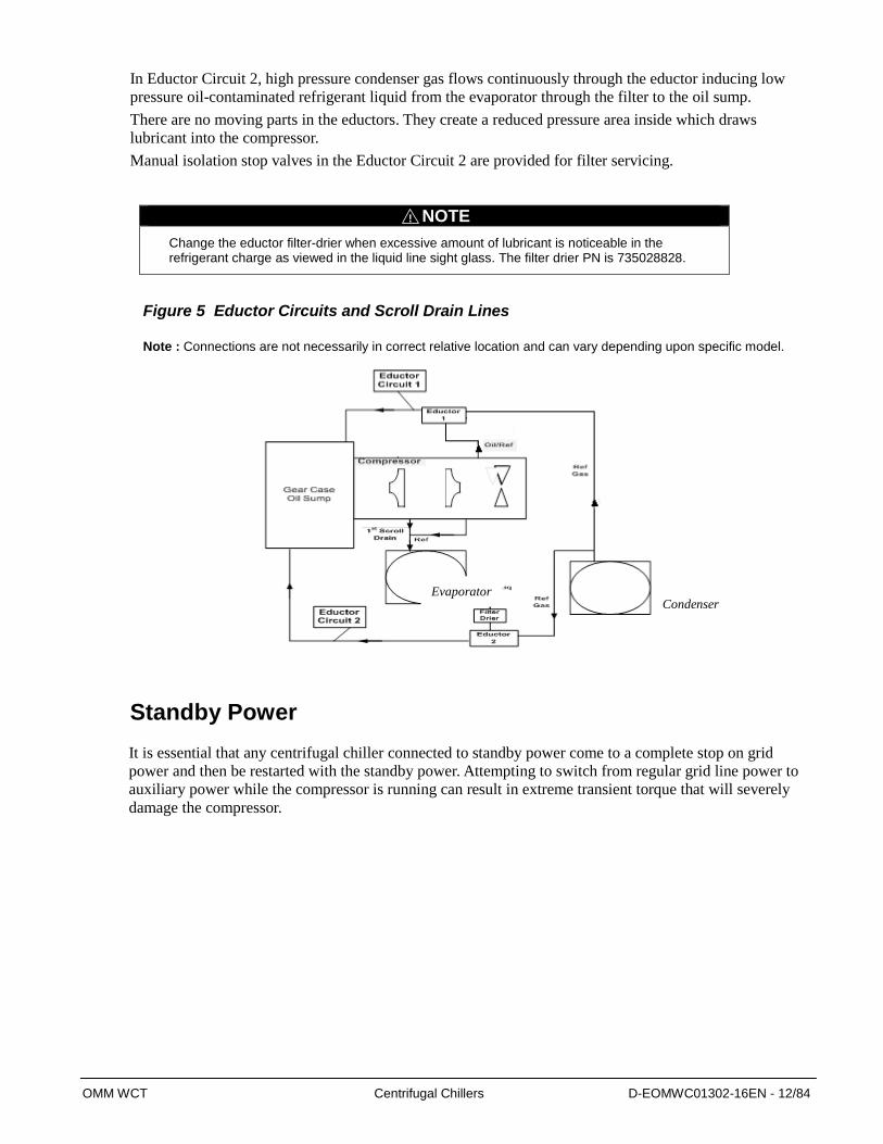
In Eductor Circuit 2, high pressure condenser gas flows continuously through the eductor inducing low
pressure oil-contaminated refrigerant liquid from the evaporator through the filter to the oil sump.
There are no moving parts in the eductors. They create a reduced pressure area inside which draws
lubricant into the compressor.
Manual isolation stop valves in the Eductor Circuit 2 are provided for filter servicing.
NOTE
Change the eductor filter-drier when excessive amount of lubricant is noticeable in the refrigerant charge as viewed in the liquid line sight glass. The filter drier PN is 735028828.
Figure 5 Eductor Circuits and Scroll Drain Lines
Note : Connections are not necessarily in correct relative location and can vary depending upon specific model.
Standby Power
It is essential that any centrifugal chiller connected to standby power come to a complete stop on grid
power and then be restarted with the standby power. Attempting to switch from regular grid line power to
auxiliary power while the compressor is running can result in extreme transient torque that will severely
damage the compressor.
!
Condenser
Evaporator
OMM WCT Centrifugal Chillers D-EOMWC01302-16EN - 13/84
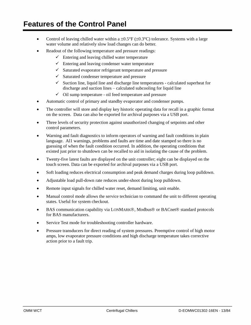
Features of the Control Panel
Control of leaving chilled water within a 0.5°F (0.3°C) tolerance. Systems with a large
water volume and relatively slow load changes can do better.
Readout of the following temperature and pressure readings:
Entering and leaving chilled water temperature
Entering and leaving condenser water temperature
Saturated evaporator refrigerant temperature and pressure
Saturated condenser temperature and pressure
Suction line, liquid line and discharge line temperatures - calculated superheat for
discharge and suction lines – calculated subcooling for liquid line
Oil sump temperature - oil feed temperature and pressure
Automatic control of primary and standby evaporator and condenser pumps.
The controller will store and display key historic operating data for recall in a graphic format
on the screen. Data can also be exported for archival purposes via a USB port.
Three levels of security protection against unauthorized changing of setpoints and other
control parameters.
Warning and fault diagnostics to inform operators of warning and fault conditions in plain
language. Al1 warnings, problems and faults are time and date stamped so there is no
guessing of when the fault condition occurred. In addition, the operating conditions that
existed just prior to shutdown can be recalled to aid in isolating the cause of the problem.
Twenty-five latest faults are displayed on the unit controller; eight can be displayed on the
touch screen. Data can be exported for archival purposes via a USB port.
Soft loading reduces electrical consumption and peak demand charges during loop pulldown.
Adjustable load pull-down rate reduces under-shoot during loop pulldown.
Remote input signals for chilled water reset, demand limiting, unit enable.
Manual control mode allows the service technician to command the unit to different operating
states. Useful for system checkout.
BAS communication capability via LONMARK, Modbus or BACnet standard protocols
for BAS manufacturers.
Service Test mode for troubleshooting controller hardware.
Pressure transducers for direct reading of system pressures. Preemptive control of high motor
amps, low evaporator pressure conditions and high discharge temperature takes corrective
action prior to a fault trip.

OMM WCT Centrifugal Chillers D-EOMWC01302-16EN - 14/84
General Description
The control panel is located on the front of the unit. There are two doors. The control panel is behind to right
door.
The centrifugal MicroTech control system consists of microprocessor-based controllers and a number of
extension modules, which vary depending on the unit size and conformation. The control system provides all
monitoring and control functions required for the controlled, efficient operation of the chiller.
The system consists of the following components:
Operator Interface Touch Screen (OITS), one per unit-provides unit information and is the primary setpoint
input instrument. It has no control function.
Unit Controller, one per chiller-controls unit and compressor functions. It is the secondary location for
setpoint input if the Interface Screen is inoperative. It is located in the control box adjacent to the OITS.
The operator can monitor all critical operating conditions by using the screens on the OITS or screen located
on the main controller. In addition to providing all normal operating controls, the MicroTech III control
system will take corrective action if the chiller is operating outside of its normal design conditions. If a fault
condition develops, the controller will shut a compressor, or the entire unit, down and activate an alarm output.
The system is password protected and only allows access by authorized personnel. Except that some basic
information is viewable and alarms can be cleared without a password. No settings can be changed.
NOTE: It is important to understand that the OITS is the operator interface device under normal conditions and
has no control function. If it is unavailable, the unit controller will be used to enter setpoint changes, view
operating parameters and operate the chiller.
EXV Controllers
Signal Converters
IGV/DDC Relays
Compressor Relays
Oil Heater Relays
Latch Relays
Oil Pump Relays
Oil Pump Overloads
Touch screen Controller
Circuits I/Os
Control
Transformer
Unit Switch,
Comp. Switches,
Circuit Bkr.
MicroTech III
Main Controller
Figure 6, Control Panel Layout

OMM WCT Centrifugal Chillers D-EOMWC01302-16EN - 15/84
Controller Description
Hardware Structure The MicroTech III control system for WCT chillers consists of a main unit controller with a number of extension
input/output I/O modules, Operator touch screen, lubrication control, miscellaneous switches and field
connections terminals.
One of the optional BAS communication modules may be included.
The MicroTech III controllers used on WCT chillers are not interchangeable with previous MicroTech II
controllers.
BACnet/IP BACnet/
MSTP
MODbus LON
Communication
Cards
AWM
MicroTech III unit controller Extension I/O Modules
PC
Touch Screen
Figure 7, Hardware layout
OMM WCT Centrifugal Chillers D-EOMWC01302-16EN - 16/84
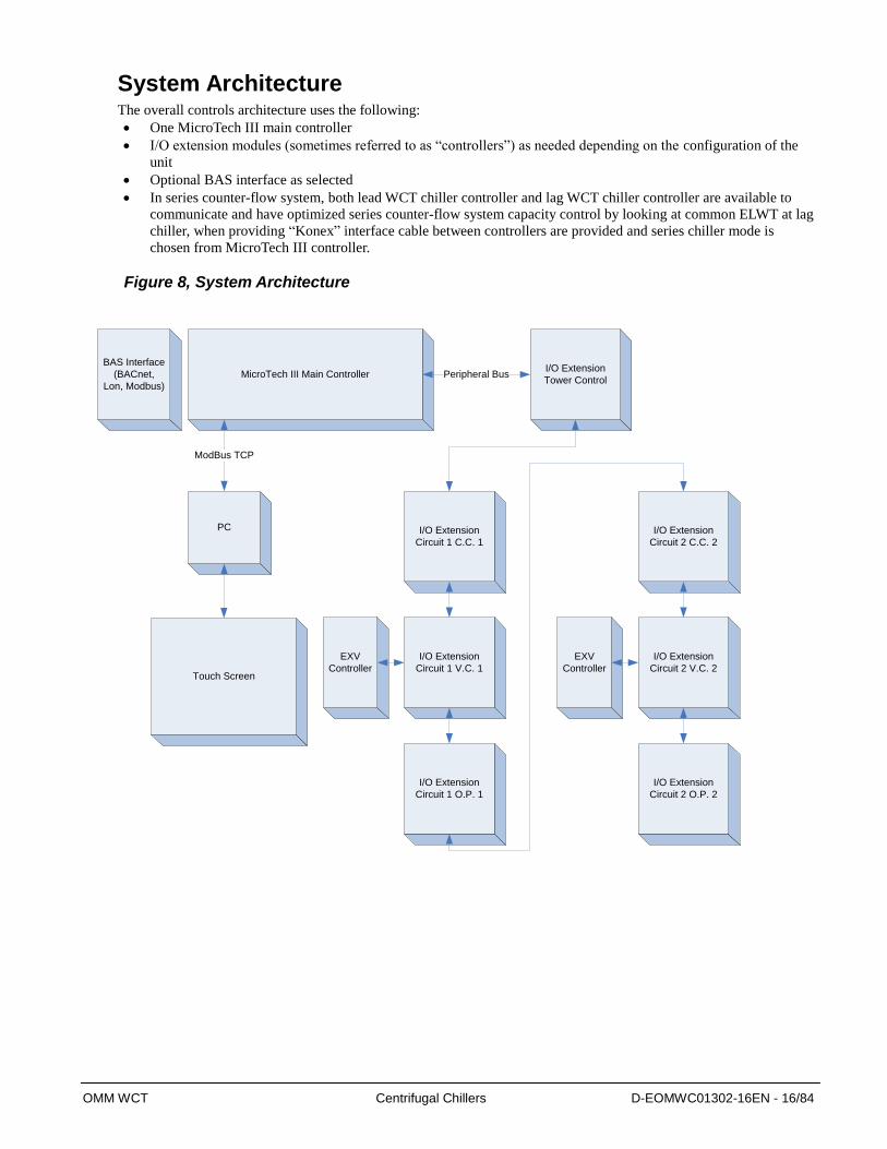
System Architecture The overall controls architecture uses the following:
One MicroTech III main controller
I/O extension modules (sometimes referred to as “controllers”) as needed depending on the configuration of the
unit
Optional BAS interface as selected
In series counter-flow system, both lead WCT chiller controller and lag WCT chiller controller are available to
communicate and have optimized series counter-flow system capacity control by looking at common ELWT at lag
chiller, when providing “Konex” interface cable between controllers are provided and series chiller mode is
chosen from MicroTech III controller.
Figure 8, System Architecture
I/O Extension
Circuit 1 C.C. 1
I/O Extension
Circuit 1 V.C. 1
I/O Extension
Circuit 1 O.P. 1
I/O Extension
Tower Control
BAS Interface
(BACnet,
Lon, Modbus)
MicroTech III Main Controller Peripheral Bus
I/O Extension
Circuit 2 C.C. 2
I/O Extension
Circuit 2 V.C. 2
I/O Extension
Circuit 2 O.P. 2
PC
ModBus TCP
Touch Screen
EXV
Controller
EXV
Controller
OMM WCT Centrifugal Chillers D-EOMWC01302-16EN - 17/84
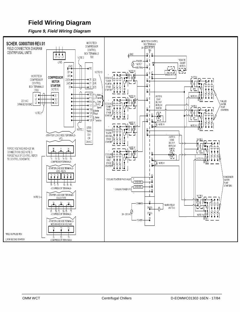
Field Wiring Diagram
Figure 9, Field Wiring Diagram
OMM WCT Centrifugal Chillers D-EOMWC01302-16EN - 18/84
Wiring Diagram Notes
1. Compressor motor starters are either factory mounted and wired or shipped separate for field mounting
and wiring. If provided by others starters must comply with Daikin specification 359A999. All line and
load side power conductors must be copper, with ampacity based on 75°C conductor rating. (Exception:
for equipment rated over 2000 volts, 90°C or 105°C rated conductors shall be used.
2. Field control wiring between the starter and the control panel is required with free-standing starters.
Minimum wire size for 115 VAC to 220 VAC is 12 GA. for a maximum length of 50 feet. If greater than
50 feet refer to Daikin for recommended wire size minimum. Wire size for 24 VAC is 18 GA. All wiring
to be installed as NEC class 1 wiring system. All 20 VAC wiring must be run in separate conduit from
115 VAC and 220 VAC wiring. Main power wiring between starter and motor terminal is factory
installed when units are supplied with unit mounted starters. Wiring of free standing starter must be
wired in accordance with NEC and connection to compressor motor terminals must be made with
copper wire and copper lugs only.
3. For optional sensor wiring see unit control diagram. It is recommended that DC wires be run separately
from 115 VAC to 220 VAC wiring.
4. A customer furnished 24 or 230 VAC power for alarm relay coil may be connected between TB3
terminals 28 power and 26 neutral of the control panel. For normally open contacts wire between 26
and 29, for normally closed wire between 26 and 27. The alarm is operator programmable. Maximum
rating of the alarm relay coil is 25 VA.
5. Remote on/off control of unit can be accomplished by installing a set of dry contacts between terminals
36 and 25.
6. Evaporator and condenser flow switches are required. Factory mounted flow switches are standard on
WCT units. Field installed flow switches must be wired as shown. If field supplied pressure differential
switches are used then these must be installed across the vessel and not the pump. Paddle flow switches
may also be field installed if desired.
7. Customer supplied 24 to 230 VAC 20 amp power for optional evaporator and condenser water pump
control power and tower fans is supplied to unit control terminals (TB3) 30 power / 31 neutral, PE
equipment ground.
8. Optional customer supplied 24-220 VAC 25 VA maximum coil rated chilled water pump relay (EP 1 and
2) may be wired as shown. This optional will cycle the chilled water pump in response to chiller
demand.
9. The condenser water pump must cycle with the unit. A customer supplied 24-220 VAC 25 VA maximum
coil rated condenser water pump relay (CP 1 and 2) is to be wired as shown. Units with free cooling
must have condenser water above 60o before starting.
10. Optional customer supplied 24-220 VAC 25 VA maximum coil rated cooling tower fan relays (C1 – C2
standard, C3 – C4 optional) may be wired as shown. This option will cycle the cooling tower fans in
order to maintain unit head pressure.
11. Auxiliary 24 VAC rated contacts in both the chilled water and condenser water pump starters should be
wired as shown and remove MJ.
12. For VFD, Wye-Delta, and solid state starters connected to six (6) terminal motors. The conductors
between the starter and motor carry phase current and selection shall be based on 58 percent of the
motor rated load amperes (RLA). Wiring of free standing starter must be in accordance with the NEC
and connection to the compressor motor terminals shall be made with copper wire and copper lugs only.
Main power wiring between the starter and motor terminals is factory installed when chillers are
supplied with unit-mounted starters.
13. Motor current has three selectable options as follows : 0-5V/0-10V/0-20mA by build in HMI.

OMM WCT Centrifugal Chillers D-EOMWC01302-16EN - 19/84
Operator Interface Touch Screen (OITS)
The operator interface touch screen (OITS) is the primary device by which commands and entries into the
control system are made. It also displays all controller data and information on a series of graphic screens.
The control panel contains a USB port that can be used for loading information to and from the control
system.
The OITS panel is mounted on a moveable arm to allow placement in a convenient position.
Figure 10, OTIS Screen Layout
Hardware Structure The controller is fitted with a 32-bit microprocessor for running the control program. There are terminals for
connection to the controlled devices (for example: solenoid valves, pumps). The program and settings are
saved permanently in FLASH memory, preventing data loss in the event of power failure without requiring a
back-up battery.
The controller connects to the OITS via a ModBus TCP communications network. It also has remote
communication access capability for BAS interface.
Software
The operating software is revised occasionally. The version can be viewed at any time by going the “About
Chiller” screen and looking at “App ver.”
OMM WCT Centrifugal Chillers D-EOMWC01302-16EN - 20/84
Unit Controller
Unit and compressor on/off switches are mounted in the control panel located adjacent to the OITS panel.
The compressor on/off switch should only be used when an immediate stop is required since the normal shut
down sequence is bypassed.
The switch panel also has a circuit breaker that interrupts power to the cooling tower fans, valves and
evaporator and condenser pumps’ control relays, if any of these are tied into the MicroTech III for control of
their operation. If these components operate independently from the chiller control, the breaker has no effect.
There is an emergency shutdown switch located on the left outside of the panel that causes an immediate
compressor shutdown.
The unit controller's function is processing data relating to the entire chiller operation. The unit controller
processes information and sends data to other devices and relays information to the OITS for graphic display.
It has a 5-line by 22 character display and keys for accessing data and changing setpoints. The unit controller
display has the same information as the OITS and can operate the chiller independently if the OITS is not
available. Inputs and outputs are shown in the following tables.
Motor Thermal Protection
The motor is protected with embedded Klixon sensors in the motor windings. If the motor temperature rises
to an unsafe level, the klixon will signal the compressor controller and the compressor will shut down.
Signal Converter Board
On medium voltage starters, the AC current signal generated by the starter is converted by the signal
converter board into a 0-5 VDC signal that is directly proportional to the compressor motor amp draw. The
amp draw signal is sent to the compressor controller.
Navigation
The Main screen is shown Main screen on page 25 is usually left on. Other of screens can be accessed from
the Tab menu or one of the three buttons at the bottom of the screen: Trend, Setting and Alarms/Warnings.
Trend will go to the Trend screen
Settings will go to a series of screens used to set setpoints.
Alarms/Warnings will go to Active Alarm with tab to select Alarm History
The figure on the following page illustrates the arrangement of the various screens available on the OITS. A
few minutes practice on an actual OITS should provide a comfortable level of confidence in navigating
through the screens.
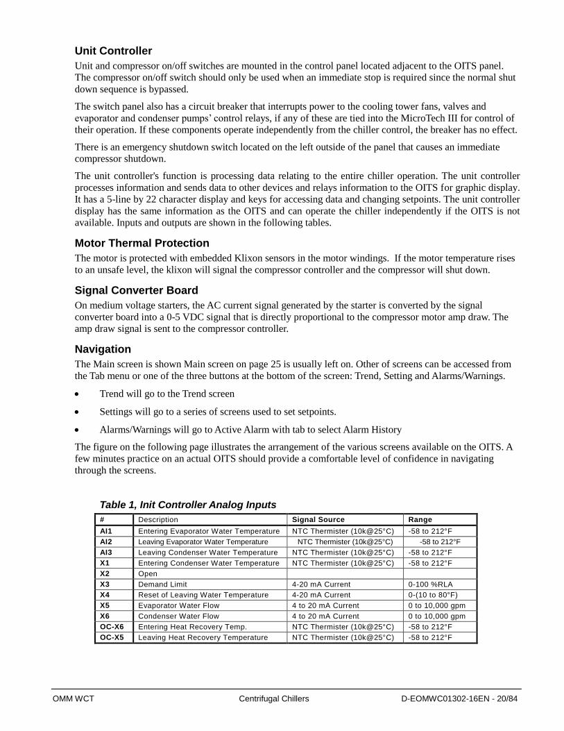
Table 1, Init Controller Analog Inputs
# Description Signal Source Range
AI1 Entering Evaporator Water Temperature NTC Thermister (10k@25°C) -58 to 212°F
AI2 Leaving Evaporator Water Temperature NTC Thermister (10k@25°C) -58 to 212°F
AI3 Leaving Condenser Water Temperature NTC Thermister (10k@25°C) -58 to 212°F
X1 Entering Condenser Water Temperature NTC Thermister (10k@25°C) -58 to 212°F
X2 Open
X3 Demand Limit 4-20 mA Current 0-100 %RLA
X4 Reset of Leaving Water Temperature 4-20 mA Current 0-(10 to 80°F)
X5 Evaporator Water Flow 4 to 20 mA Current 0 to 10,000 gpm
X6 Condenser Water Flow 4 to 20 mA Current 0 to 10,000 gpm
OC-X6 Entering Heat Recovery Temp. NTC Thermister (10k@25°C) -58 to 212°F
OC-X5 Leaving Heat Recovery Temperature NTC Thermister (10k@25°C) -58 to 212°F
OMM WCT Centrifugal Chillers D-EOMWC01302-16EN - 21/84
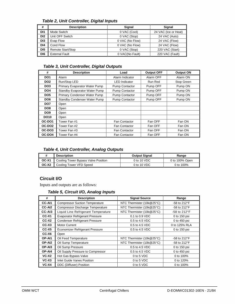
Table 2, Unit Controller, Digital Inputs
# Description Signal Signal
DI1 Mode Switch 0 VAC (Cool) 24 VAC (Ice or Heat)
DI2 Unit OFF Switch 0 VAC (Stop) 24 VAC (Auto)
DI3 Evap Flow 0 VAC (No Flow) 24 VAC (Flow)
DI4 Cond Flow 0 VAC (No Flow) 24 VAC (Flow)
DI5 Remote Start/Stop 0 VAC (Stop) 220 VAC (Start)
DI6 External Fault 0 VAC(No Fault) 220 VAC (Fault)
Table 3, Unit Controller, Digital Outputs
# Description Load Output OFF Output ON
DO1 Alarm Alarm Indicator Alarm OFF Alarm ON
DO2 Run/Stop LED LED Indicator Run Red Stop Green
DO3 Primary Evaporator Water Pump Pump Contactor Pump OFF Pump ON
DO4 Standby Evaporator Water Pump Pump Contactor Pump OFF Pump ON
DO5 Primary Condenser Water Pump Pump Contactor Pump OFF Pump ON
DO6 Standby Condenser Water Pump Pump Contactor Pump OFF Pump ON
DO7 Open
DO8 Open
DO9 Open
DO10 Open
OC-DO1 Tower Fan #1 Fan Contactor Fan OFF Fan ON
OC-DO2 Tower Fan #2 Fan Contactor Fan OFF Fan ON
OC-DO3 Tower Fan #3 Fan Contactor Fan OFF Fan ON
OC-DO4 Tower Fan #4 Fan Contactor Fan OFF Fan ON
Table 4, Unit Controller, Analog Outputs
# Description Output Signal Range
OC-X1 Cooling Tower Bypass Valve Position 0 to 10 VDC 0 to 100% Open
OC-X2 Cooling Tower VFD Speed 0 to 10 VDC 0 to 100%
Circuit I/O
Inputs and outputs are as follows:
Table 5, Circuit I/O, Analog Inputs
# Description Signal Source Range
CC-AI1 Compressor Suction Temperature NTC Thermister (10k@25°C) -58 to 212°F
CC-AI2 Compressor Discharge Temperature NTC Thermister (10k@25°C) -58 to 212°F
CC-AI3 Liquid Line Refrigerant Temperature NTC Thermister (10k@25°C) -58 to 212°F
CC-X1 Evaporator Refrigerant Pressure 0.1 to 0.9 VDC 0 to 150 psi
CC-X2 Condenser Refrigerant Pressure 0.5 to 4.5 VDC 0 to 450 psi
CC-X3 Motor Current 0.5 to 4.5 VDC 0 to 125% RLA
CC-X5 Economizer Refrigerant Pressure 0.5 to 4.5 VDC 0 to 150 psi
CC-X6 Open
OP-AI1 Oil Feed Temperature NTC Thermister (10k@25°C) -58 to 212°F
OP-AI2 Oil Sump Temperature NTC Thermister (10k@25°C) -58 to 212°F
OP-AI3 Oil Sump Pressure 0.5 to 4.5 VDC 0 to 150 psi
OP-AI4 Oil Supply Pressure to Compressor 0.5 to 4.5 VDC 0 to 450 psi
VC-X2 Hot Gas Bypass Valve 0 to 5 VDC 0 to 100%
VC-X3 Inlet Guide Vanes Position 0 to 5 VDC 0 to 120%
VC-X4 DDC (Diffuser) Position 0 to 5 VDC 0 to 100%
OMM WCT Centrifugal Chillers D-EOMWC01302-16EN - 22/84
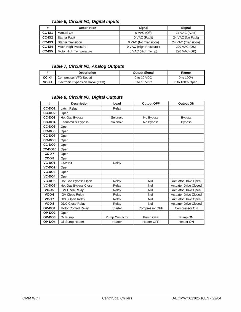
Table 6, Circuit I/O, Digital Inputs
# Description Signal Signal
CC-DI1 Manual Off 0 VAC (Off) 24 VAC (Auto)
CC-DI2 Starter Fault 0 VAC (Fault) 24 VAC (No Fault)
CC-DI3 Starter Transition 0 VAC (No Transition) 24 VAC (Transition)
CC-DI4 Mech High Pressure 0 VAC (High Pressure ) 220 VAC (OK)
CC-DI5 Motor High Temperature 0 VAC (High Temp) 220 VAC (OK)
Table 7, Circuit I/O, Analog Outputs
# Description Output Signal Range
CC-X4 Compressor VFD Speed 0 to 10 VDC 0 to 100%
VC-X1 Electronic Expansion Valve (EEV) 0 to 10 VDC 0 to 100% Open
Table 8, Circuit I/O, Digital Outputs
# Description Load Output OFF Output ON
CC-DO1 Latch Relay Relay
CC-DO2 Open
CC-DO3 Hot Gas Bypass Solenoid No Bypass Bypass
CC-DO4 Economizer Bypass Solenoid No Bypass Bypass
CC-DO5 Open
CC-DO6 Open
CC-DO7 Open
CC-DO8 Open
CC-DO9 Open
CC-DO10 Open
CC-X7 Open
CC-X8 Open
VC-DO1 EXV Init Relay
VC-DO2 Open
VC-DO3 Open
VC-DO4 Open
VC-DO5 Hot Gas Bypass Open Relay Null Actuator Drive Open
VC-DO6 Hot Gas Bypass Close Relay Null Actuator Drive Closed
VC-X5 IGV Open Relay Relay Null Actuator Drive Open
VC-X6 IGV Close Relay Relay Null Actuator Drive Closed
VC-X7 DDC Open Relay Relay Null Actuator Drive Open
VC-X8 DDC Close Relay Relay Null Actuator Drive Closed
OP-DO1 Motor Control Relay Starter Compressor OFF Compressor ON
OP-DO2 Open
OP-DO3 Oil Pump Pump Contactor Pump OFF Pump ON
OP-DO4 Oil Sump Heater Heater Heater OFF Heater ON

OMM WCT Centrifugal Chillers D-EOMWC01302-16EN - 23/84
Figure 11, OITS Screen Layout
Press Settings
Water
Modes
Motor
Valve
Tower
Alarms
Timer
Starter
Interface
Any
Screen
SETTINGS
Each Tab in
Settings has
setpoints
with range
explained on
screen
Press Alarms/Warnings
Active Alarm
Any
Screen
Alarms/Warnings
Press Trend
Trend
Any
Screen
TREND
Alarm History
Press Main
Main
Any
Screen
MAIN
Detail
Press Compressor
Compressor
Any
Screen
COMPRESSOR
Summary
Motor
Lubrication
IGV/DDC
Hot Gas
Press Evaporator
Evaporator
Any
Screen
EVAPORATOR
Press Condenser
Condenser
Any
Screen
CONDENSER
Press Economizer
Economizer
Any
Screen
ECONOMIZER
Press Expansion
Expansion
Any
Screen
EXPANSION
Press Tower
Tower
Any
Screen
TOWER
In some screen pressing the Displaying
Circuit x button will switch the value to the
other circuit.
OMM WCT Centrifugal Chillers D-EOMWC01302-16EN - 24/84
Screen Descriptions
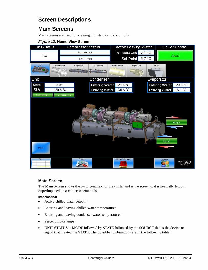
Main Screens Main screens are used for viewing unit status and conditions.
Figure 12, Home View Screen
Main Screen
The Main Screen shows the basic condition of the chiller and is the screen that is normally left on.
Superimposed on a chiller schematic is:
Information
Active chilled water setpoint
Entering and leaving chilled water temperatures
Entering and leaving condenser water temperatures
Percent motor amps
UNIT STATUS is MODE followed by STATE followed by the SOURCE that is the device or
signal that created the STATE. The possible combinations are in the following table:

OMM WCT Centrifugal Chillers D-EOMWC01302-16EN - 25/84
Table 9, UNIT STATUS Possibilities
Status Text
Auto
Off – Ice Mode Timer
Off – All Cir Disable
Off – Unit Alarm
Off – Keypad Disable
Off – Remote Switch
Off – BAS Disable
Off – Unit Switch
Off – Test Mode
Off – Seq Num Equal
Auto – Wait For Load
Auto – Evap Recirc
Auto Pump down
Note: Shutdown is the state of shutting down; vane close, postlube, etc.
COMPRESSOR STATUS is MODE followed by STATE followed by the SOURCE that is the
device or signal that created the STATE. The possible combinations are in the following table
Table 10, COMPRESSOR STATUS Possibilities
Status Text (in priority sequence) Off – Ready
Off – Cycle Timer xxx
Off - Max Comp Starts
Off – Manual Switch
Off – Oil Temperature
Off – DDC Calibrating
Off – IGV Calibrating
Off – Alarm
Test Mode
Prelube Timer xxx
Unload Timer xxx
Postlube Timer xxx
Run – Normal
Off – Exv Calibrating
Oil Pump On
Hold – Max Amps
Unload – Max Amps
Hold – Capacity Limit
Unload – Capacity Limit
Load – Discharge Temperature
Hold – Pull Down Rate
Hold – Evaporator Pressure
Unload – Evaporator Pressure
Off - Vanes Not Closed
NOTE: Timer countdown values will be shown where “(xxx)” is shown below.
OMM WCT Centrifugal Chillers D-EOMWC01302-16EN - 26/84
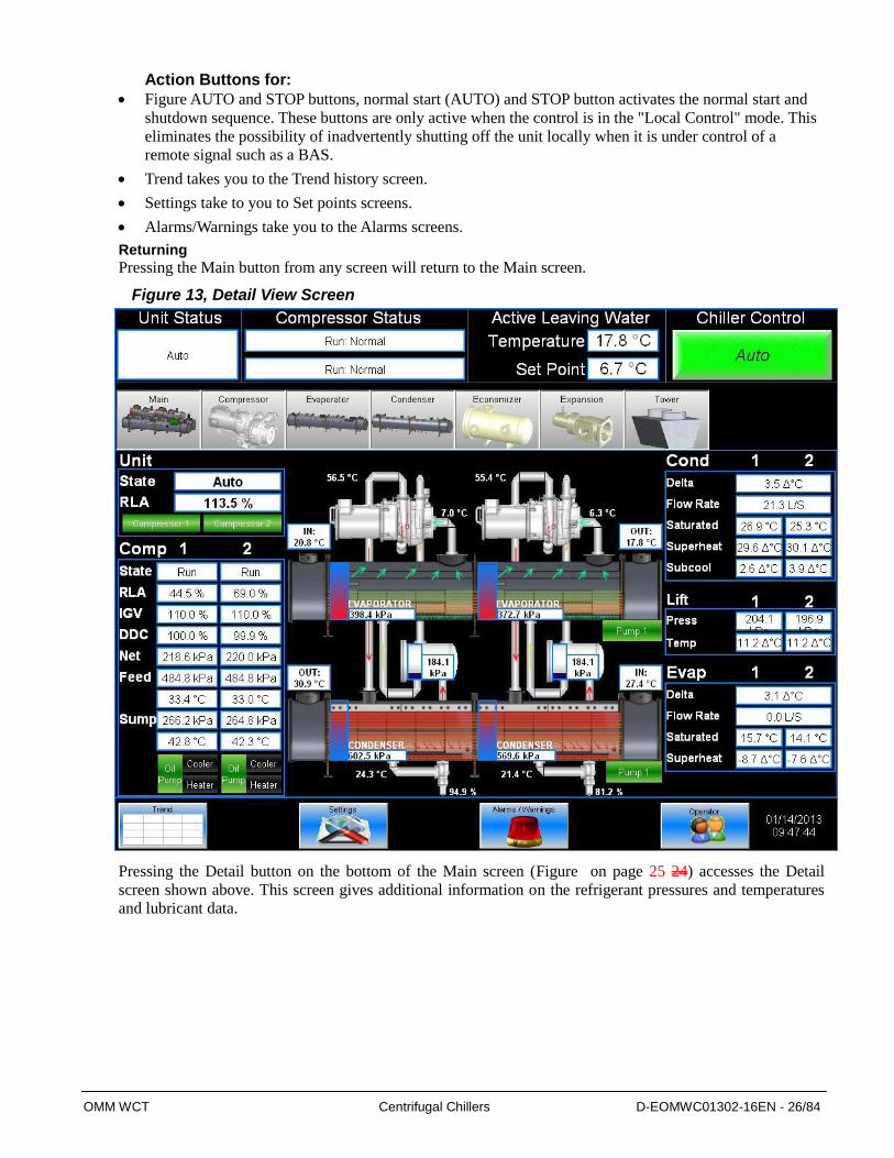
Action Buttons for:
Figure AUTO and STOP buttons, normal start (AUTO) and STOP button activates the normal start and
shutdown sequence. These buttons are only active when the control is in the "Local Control" mode. This
eliminates the possibility of inadvertently shutting off the unit locally when it is under control of a
remote signal such as a BAS.
Trend takes you to the Trend history screen.
Settings take to you to Set points screens.
Alarms/Warnings take you to the Alarms screens.
Returning
Pressing the Main button from any screen will return to the Main screen.
Figure 13, Detail View Screen
Pressing the Detail button on the bottom of the Main screen (Figure on page 25 24) accesses the Detail
screen shown above. This screen gives additional information on the refrigerant pressures and temperatures
and lubricant data.
OMM WCT Centrifugal Chillers D-EOMWC01302-16EN - 27/84
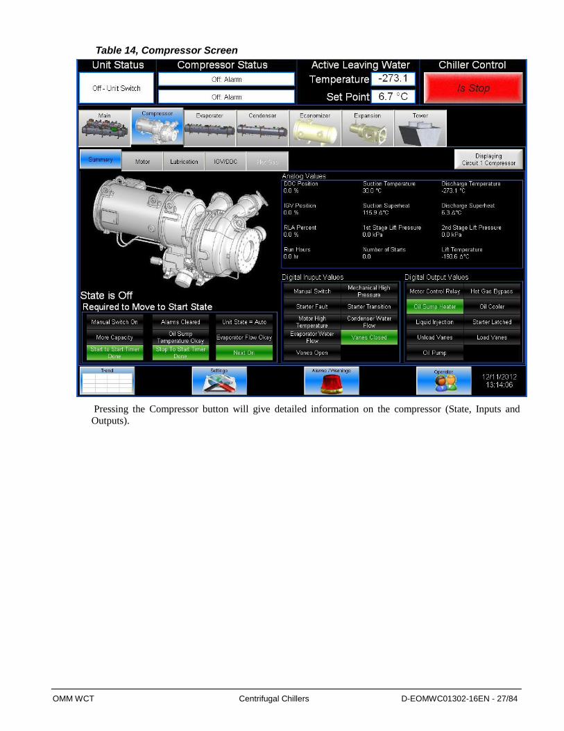
Table 14, Compressor Screen
Pressing the Compressor button will give detailed information on the compressor (State, Inputs and
Outputs).
OMM WCT Centrifugal Chillers D-EOMWC01302-16EN - 28/84
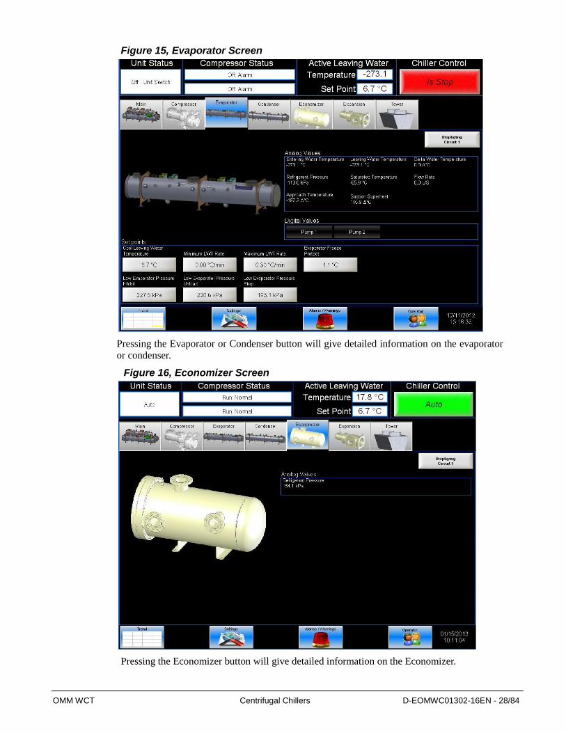
Figure 15, Evaporator Screen
Pressing the Evaporator or Condenser button will give detailed information on the evaporator
or condenser.
Figure 16, Economizer Screen
Pressing the Economizer button will give detailed information on the Economizer.

OMM WCT Centrifugal Chillers D-EOMWC01302-16EN - 29/84
Figure 17, Expansion Screen
Pressing the Expansion button will give detailed information on the Expansion.
SET Screens The set screens on the Interface Panel are used to input the many setpoints associated with equipment
of this type. MicroTech III provides an extremely simple method for accomplishing this. (NOTE: If
the Interface Panel is unavailable, the unit controller can be used to change setpoints.) Appropriate
setpoints are factory set and checked by DaikinService or Factory Authorized Service Company during
commissioning. However, adjustments and changes are often required to meet job conditions. Certain
settings involving pumps and tower operation are field set.
Pressing the SET button found on almost every screen accesses the last SET screen used or the
SERVICE screen, whichever of the two was used last.
When in any SET screen, pressing the SET button again will toggle to the SERVICE screen shown on
page 43.
The next figure shows the Settings screen with WATER setpoints selected. The various setpoint groups
are in tabs on the top of the setting screen. Each button contains a number of setpoints grouped
together by similar content. The WATER button (as shown) contains various setpoints relating to water
temperatures.
NOTE: Some setpoints that do not apply to a particular application may still be listed on the screen.
They will be inactive, grayed out, and can be ignored. For example, of setpoints Ice LWT will only be
active depending on the unit mode selected in the MODE setpoints .

OMM WCT Centrifugal Chillers D-EOMWC01302-16EN - 30/84
Figure 18, A Typical SETPOINT Screen
Procedure for Changing a Setpoint
A list of setpoints, their default value, their available setting range, and password authority are
in Table 20 on page 57.
1. Press the applicable Setpoint Group Button. A complete explanation of setpoint content of each
group follows this section.
2. Select the desired setpoint.
3. Press button indicating that you wish to change a setpoint value. The KEYBOARD screen will be
turned on automatically for entering the password.
O = Operator level password is 5321
M = Manager level (password is reserved for Daikin service personnel)
T = Technician level (password is reserved for authorized technicians)
4. Press the appropriate numbers in the numeric keyboard to enter the password. There is a small
delay between pressing the keypad and recording the entry. Be sure that an asterisk appears in the
window before pressing the next number. Press Green Check button to return to the Settings
screen. The password will remain open for 15 minute after initiation and does not need to be re-
entered during this period.
5. Press button again.
6. The numeric keypad will appear again select the desired value by pressing the numbered buttons.
Press Green Check to enter the value or Red X to cancel the transaction.
Setpoint
Groups
Setpoint
Description
Setpoints
Initiate Change
Button
Numeric
Keypad
Action
Buttons
To Trend
Screen
To Setting
Screen
To Alarm
Screen
Enter
Password
OMM WCT Centrifugal Chillers D-EOMWC01302-16EN - 31/84
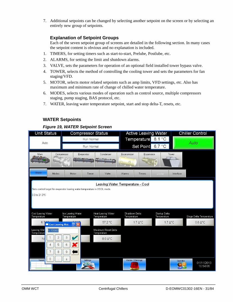
7. Additional setpoints can be changed by selecting another setpoint on the screen or by selecting an
entirely new group of setpoints.
Explanation of Setpoint Groups Each of the seven setpoint group of screens are detailed in the following section. In many cases
the setpoint content is obvious and no explanation is included.
1. TIMERS, for setting timers such as start-to-start, Prelube, Postlube, etc.
2. ALARMS, for setting the limit and shutdown alarms.
3. VALVE, sets the parameters for operation of an optional field installed tower bypass valve.
4. TOWER, selects the method of controlling the cooling tower and sets the parameters for fan
staging/VFD.
5. MOTOR, selects motor related setpoints such as amp limits, VFD settings, etc. Also has
maximum and minimum rate of change of chilled water temperature.
6. MODES, selects various modes of operation such as control source, multiple compressors
staging, pump staging, BAS protocol, etc.
7. WATER, leaving water temperature setpoint, start and stop delta-T, resets, etc.
WATER Setpoints
Figure 19, WATER Setpoint Screen
OMM WCT Centrifugal Chillers D-EOMWC01302-16EN - 32/84
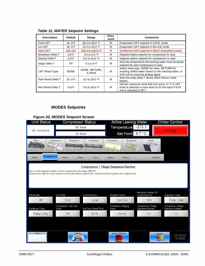
Table 11, WATER Setpoint Settings
Description Default Range Pass-word
Comments
Cool LWT 44. 0F 35.0 to 80.0 F M Evaporator LWT setpoint in COOL mode
Ice LWT 25. 0F 15.0 to 35.0 F M Evaporator LWT setpoint in the ICE mode
Heat LWT 135. 0F 100.0 to 150.0 F M Condenser LWT setpoint in HEAT (Templifier) mode
Shutdown Delta T 3.0F 0.0 to 3.0 F M Degrees below setpoint for compressor to stop.
Startup Delta T 3.0F 0.0 to 10.0 F M Degrees above setpoint for compressor to start.
Stage Delta T 1ºF 0.5 to 5F M Sets the temperature the leaving water must be below setpoint for next compressor to start.
LWT Reset Type NONE NONE, RETURN,
4-20mA M
Select reset type, NONE for none, RETURN for reseting chilled water based on the entering water, or 4-20 mA for external analog signal
Start Reset Delta T 10. 0F 0.0 to 20.0 F M Sets the evap delta-T above which Return reset begins.
Max Reset Delta T 0.0F 0.0 to 20.0 F M Set the maximum reset that can occur, in °F if LWT reset is selected or max reset at 20 mA input if 4-20 mA is selected in SP7
MODES Setpoints
Figure 20, MODES Setpoint Screen
OMM WCT Centrifugal Chillers D-EOMWC01302-16EN - 33/84
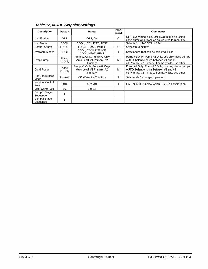
Table 12, MODE Setpoint Settings
Description Default Range Pass-word
Comments
Unit Enable OFF OFF, ON O OFF, everything is off. ON, Evap pump on, comp, cond pump and tower on as required to meet LWT
Unit Mode COOL COOL, ICE, HEAT, TEST Selects from MODES in SP4
Control Source LOCAL LOCAL, BAS, SWITCH O Sets control source
Available Modes COOL COOL, COOL/ICE, ICE,
COOL/HEAT, HEAT T Sets modes that can be selected in SP 2
Evap Pump Pump
#1 Only
Pump #1 Only, Pump #2 Only, Auto Lead, #1 Primary, #2
Primary M
Pump #1 Only, Pump #2 Only, use only these pumps AUTO, balance hours between #1 and #2 #1 Primary, #2 Primary, if primary fails, use other
Cond Pump Pump
#1 Only
Pump #1 Only, Pump #2 Only, Auto Lead, #1 Primary, #2
Primary M
Pump #1 Only, Pump #2 Only, use only these pumps AUTO, balance hours between #1 and #2 #1 Primary, #2 Primary, if primary fails, use other
Hot Gas Bypass Mode
Normal Off, Water LWT, %RLA T Sets mode for hot gas operaton
Hot Gas Control Point
30% 20 to 70% T LWT or % RLA below which HGBP solenoid is on
Max. Comp. ON 16 1 to 16
Comp 1 Stage Sequence
1
Comp 2 Stage Sequence
1

OMM WCT Centrifugal Chillers D-EOMWC01302-16EN - 34/84
MOTOR Setpoint Screen
Figure 21, MOTOR Setpoint Screen
Table 13, MOTOR Setpoint Settings
Description Default Range Pass-word
Comments
Demand Limit Enable OFF OFF, ON O ON sets %RLA at 0% for 4 mA external signal and at 100% RLA for 20 mA signal
Minimum Amps 40% 20 to 80% T % RLA below which unloading is inhibited
Maximum Amps 100% 40 to 100% T % RLA above which loading is inhibited (Load Limit)
Nameplate RLA Not used on WSC/WDC models
Soft Load Enable OFF OFF, ON M Soft load on or off
Initial Soft Load Amp Limit
40% 20 to 100% M Initial amps as % of RLA
Soft Load Ramp 5 min 1 to 60 min M Time period to go from initial load point (% RLA) set in SP 5 to 100% RLA
Minimum Rate 0.1
F/min 0.0 to 5.0 F/min M
Additional compressor can start if LWT change is below setpoint.
Maximum Rate 0.5
F/min 0.1 to 5.0 F/min M
Inhibits loading if LWT change exceed the setpoint value.
Nominal Capacity 0 to 9999 Tons Determines when to shut off a compressor
Oil No Start Diff (above Evap Temp)
40 F 30 to 60 F T Minimum Delta-T between oil sump temperature and saturated evaporator temperature
VFD No No, Yes T VFD on unit or not
Minimum Speed 70% 60 to 100% T Min VFD speed, has priority over Speed @ 0 Lift & Lift @ 100 % Speen
Speed @ 0 Lift 50% 0 to 100% T Lift @ min speed as a % of 100 % lift
Lift @ 100% Speed 40 F 30 to 60 F T Temp lift at 100 % speed (cond sat – evap sat temp)
OMM WCT Centrifugal Chillers D-EOMWC01302-16EN - 35/84
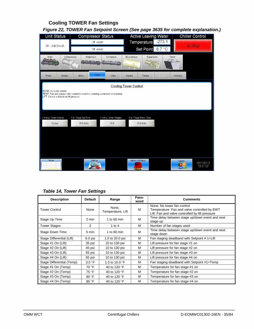
Cooling TOWER Fan Settings
Figure 22, TOWER Fan Setpoint Screen (See page 3635 for complete explanation.)
Table 14, Tower Fan Settings
Description Default Range Pass-word
Comments
Tower Control None None,
Temperature, Lift M
None: No tower fan control Temperature: Fan and valve controlled by EWT Lift: Fan and valve controlled by lift pressure
Stage Up Time 2 min 1 to 60 min M Time delay between stage up/down event and next stage up
Tower Stages 2 1 to 4 M Number of fan stages used
Stage Down Time 5 min 1 to 60 min M Time delay between stage up/down event and next stage down
Stage Differential (Lift) 6.0 psi 1.0 to 20.0 psi M Fan staging deadband with Setpoint # 1=Lift
Stage #1 On (Lift) 35 psi 10 to 130 psi M Lift pressure for fan stage #1 on
Stage #2 On (Lift) 45 psi 10 to 130 psi M Lift pressure for fan stage #2 on
Stage #3 On (Lift) 55 psi 10 to 130 psi M Lift pressure for fan stage #3 on
Stage #4 On (Lift) 65 psi 10 to 130 psi M Lift pressure for fan stage #4 on
Stage Differential (Temp) 3.0 F 1.0 to 10.0 F M Fan staging deadband with Setpoint #1=Temp
Stage #1 On (Temp) 70 F 40 to 120 F M Temperature for fan stage #1 on
Stage #2 On (Temp) 75 F 40 to 120 F M Temperature for fan stage #2 on
Stage #3 On (Temp) 80 F 40 to 120 F M Temperature for fan stage #3 on
Stage #4 On (Temp) 85 F 40 to 120 F M Temperature for fan stage #4 on
OMM WCT Centrifugal Chillers D-EOMWC01302-16EN - 36/84
Explanation of Tower Control Settings
MicroTech III control can control cooling tower fan stages, a tower bypass valve, and/or a tower fan VFD
if the chiller has a dedicated cooling tower.
The Tower Bypass Valve position will always control the Tower Fan Staging if Valve Setpoint, Stage
Setpoint is selected. Fan staging is determined by Min & Max Tower Valve Position.
There are five possible tower control strategies as noted below and explained in detail later in this section.
They are selected from SETPOINT TOWER SP2.
1. NONE, Tower fan staging only. In this mode the tower fan staging (up to 4 stages) is controlled by either
the condenser Entering Water Temperature (EWT) or LIFT pressure (difference between the condenser
and evaporator pressures). Tower bypass or fan speed are not controlled.
2. VALVE SP, Tower staging with low-limit controlled bypass valve. In this mode the tower fans are
controlled as in #1 plus a tower bypass valve is controlled to provide a minimum condenser EWT. There
is no interconnection between the fan control and the valve control.
3. VALVE STAGE, Tower staging with stage controlled bypass valve. In this mode the bypass valve controls
between fan stages to smooth the control and reduce fan cycling
4. VFD STAGE. In this mode a VFD controls the first fan. Up to 3 more fans are staged on and off and there
is no bypass valve.
5. VALVE/VFD, Tower fan control with VFD plus bypass valve control.
Tower Fan Staging Only (NONE)
The following settings are used for the Tower Fan Staging Only mode, (SP= setpoint)
1) TOWER SETPOINT Screen
i) Tower Control. Select TEMP if control is based on condenser EWT or LIFT if based on
compressor lift expressed in psi.
ii) Valve/VFD Control. Select NONE for no bypass valve or fan VFD control.
iii) Tower Stages. Select one to four fan outputs depending on the number of fan stages to be used.
More than one fan can be used per stage through the use of relays.
iv) Stage up Time. Select STAGE UP TIME from 1 to 60 minutes. The default value of 2 minutes is
probably a good starting point. The value may need to be adjusted later depending on actual
system operation.
v) Stage down Time. Select STAGE DOWN TIME from 1 to 60 minutes. The default value of 5
minutes is probably a good starting point. The value may need to be adjusted later depending on
actual system operation.
2) If TEMP is selected in Tower Control, use
i) Stage Diff. Select STAGE DIFFERENTIAL in °F, start with default of 3 °F.
ii) Stage #1-4 On (Temp). Set the STAGE ON temperatures consistent with the temperature range
over which the condenser EWT is desired to operate. The default values of 70F, 75F, 80F and
85F are a good place to start in climates with moderate wet bulb temperatures. The number of
STAGE ON setpoints used must be the same as Tower Stages.
3) If LIFT is selected in Tower Control, use
i) Stage Diff. Select STAGE DIFFERENTIAL in PSI. Start with default of 6 PSI.
ii) Stage #1-4 On (Lift). Start with default setpoints. The number of STAGE ON setpoints used must
be the same as Tower Stages.
OMM WCT Centrifugal Chillers D-EOMWC01302-16EN - 37/84
Tower Fan Staging With Bypass Valve Controlling Minimum EWT (VALVE SP) 1) TOWER SETPOINT Screen
a) Tower Control. Select TEMP if control is based on condenser EWT or LIFT if based on compressor lift
expressed in psi.
b) Valve/VFD Control. Select Valve SP for control of bypass valve based on temperature or lift.
c) Tower Stages. Select one to four fan outputs depending on the number of fan stages to be used. More
than one fan can be used per stage through the use of relays.
d) Stage up Time. Select STAGE UP TIME from 1 to 60 minutes. The default value of 2 minutes is
probably a good starting point. The value may need to be adjusted later depending on actual system
operation.
e) Stage down Time. Select STAGE DOWN TIME from 1 to 60 minutes. The default value of 5 minutes is
probably a good starting point. The value may need to be adjusted later depending on actual system
operation.
f) If TEMP is selected in SP1, use
i) Stage Diff. Select STAGE DIFFERENTIAL in °F, start with default of 3 °F.
ii) Stage #1-4 On (Temp). Set the STAGE ON temperatures consistent with the temperature range over
which the condenser EWT is desired to operate. The default values of 70F, 75F, 80F and 85F are
a good place to start in climates with moderate wet bulb temperatures. The number of STAGE ON
setpoints used must be the same as Tower Stages.
g) If LIFT is selected in Tower Control, use
i) Stage Diff. Select STAGE DIFFERENTIAL in PSI. Start with default of 6 PSI.
ii) Stage #1 On (Lift). Start with default setpoints. The number of STAGE ON setpoints used must be
the same as Tower Stages.
2) VALVE SETPOINT Screen
a) Valve Type, Select NC or NO depending if valve is closed to tower with no control power or open to
tower with no control power.
b) If TEMP was selected for fan control above, use
i) Valve Setpoint (Temp), Set the VALVE TARGET (setpoint), usually 5 degrees below the minimum
fan stage setpoint established in TOWER Stage 4 On (Temp). This keeps full flow through the tower
until the last fan is staged off.
ii) Valve Deadband (Temp), Set VALVE DEADBAND, the default of 2 °F is a
good place to start.
iii) Minimum Start Position, Set MINIMUM VALVE POSITION when EWT is at or below Temp -
Minimum Position. Default is 0%.
iv) Temp-Minimum Position, Set the EWT at which the valve position will be at (Minimum Start
Position). Default is 60F.
v) Minimum Start Position, Set MINIMUM VALVE POSITION when EWT is at or below Temp -
Minimum Position. Default is 0%.
vi) Temp -Minimum Position, Set the EWT at which the valve position is set to allow the fans to stage
up (Minimum Start Position). Default is 60F.
vii) Maximum Start Position, Set the initial valve position when EWT is at or above Temp-Maximum
Position. Default is 100%.
Temp-Maximum Position, Set the EWT at which initial valve position is set to Minimum Start
Position. Default is 90F.
viii) Valve Control Range (Min), Set the minimum position to which the valve can go. Default is 10%.
ix) Valve Control Range (Max), Set the maximum position to which the valve can go. Default is 100%.
OMM WCT Centrifugal Chillers D-EOMWC01302-16EN - 38/84
x) Error Gain, Set the control gain for error. Default is 25.
xi) Slope Gain, Set the control gain for slope. Default is 25.
NOTE: Setpoints Error Gain and Slope Gain are site specific dealing with system fluid mass,
component size and other factors affecting the reaction of the system to control inputs. These
setpoints should be set by personnel experienced with setting up this type of control.
c) If LIFT was selected for fan control, use
i) Valve Target, Set the VALVE TARGET (setpoint), usually 30 psi below the minimum fan stage
setpoint established in TOWER Stage #1 On (Lift). This keeps full flow through the tower until the
last fan is staged off.
ii) Valve Deadband (lift), Set VALVE DEADBAND, the default of 6 psi is a good place to start.
iii) Minimum Start Position, Set MINIMUM VALVE POSITION when EWT is at or below Temp-
Maximum Position. Default is 0%.
iv) Temp-Maximum Position, Set the EWT at which the valve position will be at (Minimum Start
Position). Default is 60F.
v) Valve Control Range (Min), Set the minimum position to which the valve can go. Default is 10%.
vi) Valve Control Range (Max), Set the maximum position to which the valve can go. Default is 100%.
vii) Error Gain, Set the control gain for error. Default is 25.
viii) Slope Gain, Set the control gain for slope. Default is 25.
NOTE: Setpoints Error Gain and Slope Gain are site specific dealing with system fluid mass, component
size and other factors affecting the reaction of the system to control inputs. These setpoints should be set
by personnel experienced with setting up this type of control.
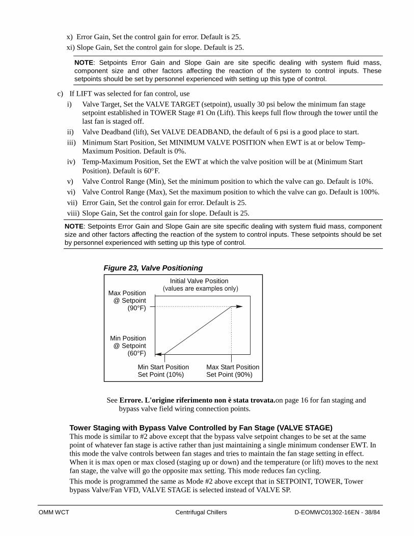
Figure 23, Valve Positioning
See Errore. L'origine riferimento non è stata trovata.on page 16 for fan staging and
bypass valve field wiring connection points.
Tower Staging with Bypass Valve Controlled by Fan Stage (VALVE STAGE) This mode is similar to #2 above except that the bypass valve setpoint changes to be set at the same
point of whatever fan stage is active rather than just maintaining a single minimum condenser EWT. In
this mode the valve controls between fan stages and tries to maintain the fan stage setting in effect.
When it is max open or max closed (staging up or down) and the temperature (or lift) moves to the next
fan stage, the valve will go the opposite max setting. This mode reduces fan cycling.
This mode is programmed the same as Mode #2 above except that in SETPOINT, TOWER, Tower
bypass Valve/Fan VFD, VALVE STAGE is selected instead of VALVE SP.
Initial Valve Position
Max Start PositionSet Point (90%)
Min Start PositionSet Point (10%)
Max Position@ Setpoint
(90°F)
Min Position@ Setpoint
(60°F)

OMM WCT Centrifugal Chillers D-EOMWC01302-16EN - 39/84
Fan VFD, No Bypass Valve (VFD STAGE)
The fan VFD mode assumes the tower is driven by one large fan. Set up is as above except in
SETPOINT, TOWER, Tower bypass Valve/Fan VFD, VALVE/VFD is selected.
Unit Controller Supplements to Tower Control The following is intended to clarify the Tower: Error Gain and Slope Gain set points found on under the
OITS VALVE group of setpoints, and on the Unit controller mask “SET TOWER Stage #1 On (Temp).
PD Control Loop
The Tower is governed with two Proportional and Derivative (PD) control loops, and is applied with a
step and wait philosophy**. One PD loop controls the tower fan VFD and the second controls the tower
bypass value. The input to both PD control loops is the sum of the error signal and the tower slope. The
following two set points apply to both control loops.
Error Gain
The error signal is used to correct the current tower setting based on the difference between the tower
setpoint and its feedback signal*. The Error Gain setpoint is used to increase or decrease the control
logic’ sensitivity to this input. The default setting is 25 with an adjustment range from 10 to 99.
Increasing this setting will increase the controls response to an error between the tower target and
feedback signal.
Slope Gain
The slope signal is used to correct the current tower setting based on the direction and rate of change in
the tower feedback signal*. The Slope Gain setpoint is used to increase or decrease the control logic’
sensitivity to this input. The default setting is 25 with an adjustment range from 10 to 99. Increasing
this setting will increase the controls response to the direction and rate of change in the tower feedback
signal.
Tuned Operation
By independently adjusting these gain settings you can tune the tower controls response to the system
installed.
* The tower feedback signal is determined by the Tower Control method selected (either condenser
return water Temp, or compressor/s Lift temp of the chiller.
** The step and wait philosophy has a wait period that is adjustable in the Unit controllers series of
Advanced Setpoint mask, specifically “Adv Set#9 Tower Ctrl”. Reducing the Tower Update Timer
(TUT) from its default value of 12 seconds, will speed up the tower reaction time. This is useful on
chiller systems with very short tower water loops.
This mask also allows the adjust of the minimum Tower VFD speed.
Caution, reducing the TUT time has the same effect as increasing the gains as described above. That is,
the tower is making corrections more often. If you need to shorten the TUT (for a small loop), then you
should also reduce the gains to compensate.
OMM WCT Centrifugal Chillers D-EOMWC01302-16EN - 40/84
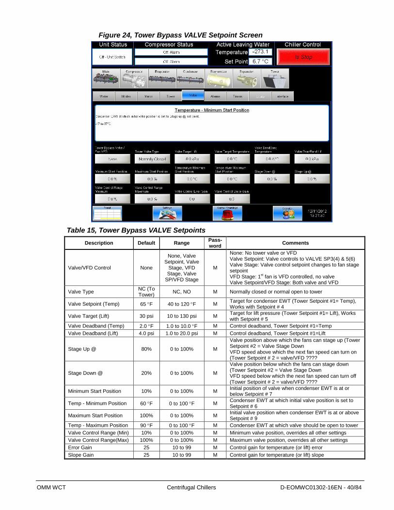
Figure 24, Tower Bypass VALVE Setpoint Screen
Table 15, Tower Bypass VALVE Setpoints
Description Default Range Pass- word
Comments
Valve/VFD Control None
None, Valve Setpoint, Valve
Stage, VFD Stage, Valve
SP/VFD Stage
M
None: No tower valve or VFD Valve Setpoint: Valve controls to VALVE SP3(4) & 5(6) Valve Stage: Valve control setpoint changes to fan stage setpoint VFD Stage: 1
st fan is VFD controlled, no valve
Valve Setpoint/VFD Stage: Both valve and VFD
Valve Type NC (To Tower)
NC, NO M Normally closed or normal open to tower
Valve Setpoint (Temp) 65 F 40 to 120 F M Target for condenser EWT (Tower Setpoint #1= Temp), Works with Setpoint # 4
Valve Target (Lift) 30 psi 10 to 130 psi M Target for lift pressure (Tower Setpoint #1= Lift), Works with Setpoint # 5
Valve Deadband (Temp) 2.0 F 1.0 to 10.0 F M Control deadband, Tower Setpoint #1=Temp
Valve Deadband (Lift) 4.0 psi 1.0 to 20.0 psi M Control deadband, Tower Setpoint #1=Lift
Stage Up @ 80% 0 to 100% M
Valve position above which the fans can stage up (Tower Setpoint #2 = Valve Stage Down VFD speed above which the next fan speed can turn on (Tower Setpoint # 2 = valve/VFD ????
Stage Down @ 20% 0 to 100% M
Valve position below which the fans can stage down (Tower Setpoint #2 = Valve Stage Down VFD speed below which the next fan speed can turn off (Tower Setpoint # 2 = valve/VFD ????
Minimum Start Position 10% 0 to 100% M Initial position of valve when condenser EWT is at or below Setpoint # 7
Temp - Minimum Position 60 F 0 to 100 F M Condenser EWT at which initial valve position is set to Setpoint # 6
Maximum Start Position 100% 0 to 100% M Initial valve position when condenser EWT is at or above Setpoint # 9
Temp - Maximum Position 90 F 0 to 100 F M Condenser EWT at which valve should be open to tower
Valve Control Range (Min) 10% 0 to 100% M Minimum valve position, overrides all other settings
Valve Control Range(Max) 100% 0 to 100% M Maximum valve position, overrides all other settings
Error Gain 25 10 to 99 M Control gain for temperature (or lift) error
Slope Gain 25 10 to 99 M Control gain for temperature (or lift) slope

OMM WCT Centrifugal Chillers D-EOMWC01302-16EN - 41/84
ALARMS Setpoint
Figure 25, ALARMS Setpoint Screen
Table 15, ALARM Setpoints
Description Default Range Pass-word Comments
Low Evap Pressure-Inhibit 33 psi 20 to 45 psi T Min evap pressure – inhibit loading
Low Evap Pressure-Unload 31 psi 20 to 45 psi T Min evap pressure – unload compressor
Low Evap Pressure, Stop 29 psi 10 to 45 psi T Min evap pressure – stop compressor
High Condenser Pressure 140 psi 120 to 240 psi T Max discharge pressure, stop compressor
High Discharge Temp-Load 170 F 120 to 240 F T Max discharge gas temp – load comp
High Discharge Temp-Shutdown 190 F 120 to 240 F T Max discharge gas temp, stop compressor
Surge Temperature Limit 6 2 – 25 ° F T See screen above
Surge Slope Limit 20 1 – 99 ° F/min. T Surge slope temp that triggers alarm
Motor Current Threshold 10% 3% to 99% T Min %RLA to consider motor off
Evaporator Freeze 34.0 F -9.0 to 45.0 F T Minimum evap. sat. temp. to start pump
Condenser Freeze 34.0 F -9.0 to 45.0 F T Minimum cond. sat. temp. to start pump
High Oil Feed Temperature 140 F 120 to 240 F T Max oil temperature
Low Oil Delta Temperature 30 °F 20 to 80 °.F T Min Delta-T (sat evap minus oil temp)
Low Net Oil Pressure 22 psi 0 to 76 psi T Min net pressure (feed minus sump)
Low Lift Pressure 14 psi 0 to 73 psi M Min pressure (cond – evap press)

OMM WCT Centrifugal Chillers D-EOMWC01302-16EN - 42/84
TIMERS Setpoint
Figure 26, TIMERS Setpoint Screen
Table 16, TIMER Setpoints
Description Default Range Pass-word
Comments
Evap Recirculate 0.5 min 0.2 to 5 min M Time that evaporator pump must run before compressor start
Start-Start 40 min 15 to 60 min M Time from when compressor starts to when it can start again
Stop-Start 3 min 3 to 20 min M Time from when compressor stops to when it can restart
Prelube Timer 30 sec 10 to 240 sec T Time compressor must prelube before starting
Full Load Timer 30 sec 5 to 60 sec T Time compressor must load for full open vanes
Unload Timer 30 sec 10 to 240 sec T Time compressor will unload before going to postlube
Postlube Timer 30 sec 10 to 240 sec T Time for postlube before compressor can stop
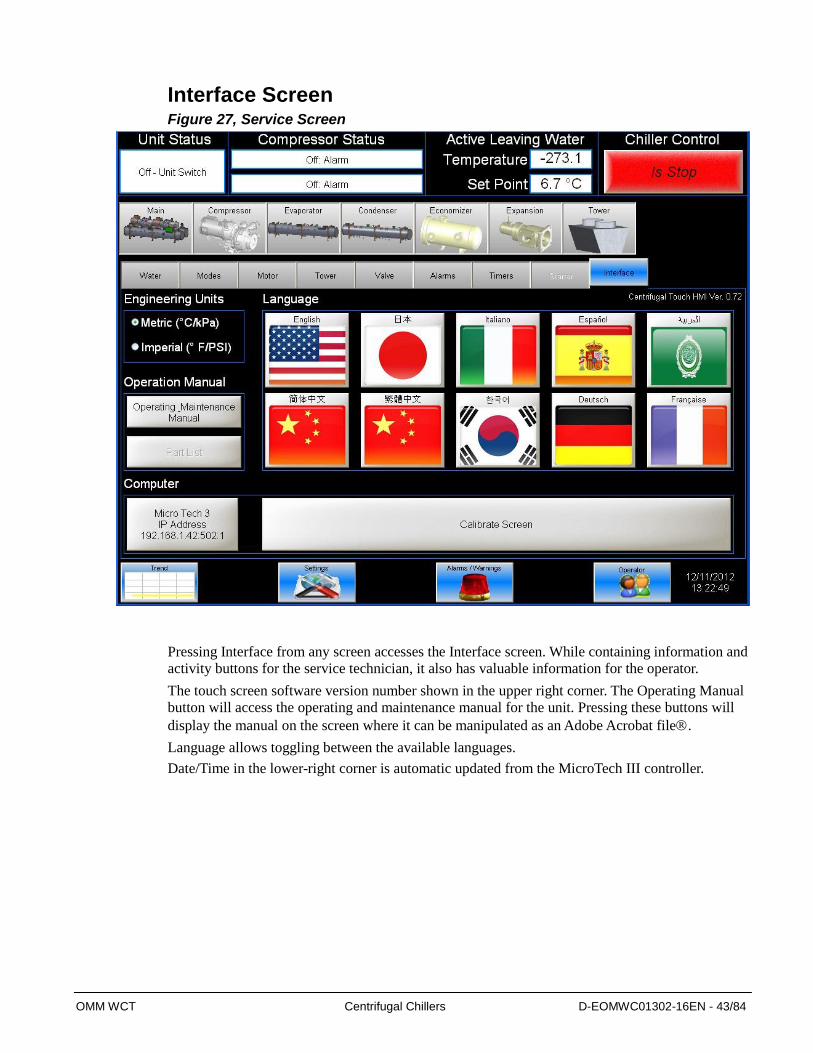
OMM WCT Centrifugal Chillers D-EOMWC01302-16EN - 43/84
Interface Screen Figure 27, Service Screen
Pressing Interface from any screen accesses the Interface screen. While containing information and
activity buttons for the service technician, it also has valuable information for the operator.
The touch screen software version number shown in the upper right corner. The Operating Manual
button will access the operating and maintenance manual for the unit. Pressing these buttons will
display the manual on the screen where it can be manipulated as an Adobe Acrobat file.
Language allows toggling between the available languages.
Date/Time in the lower-right corner is automatic updated from the MicroTech III controller.
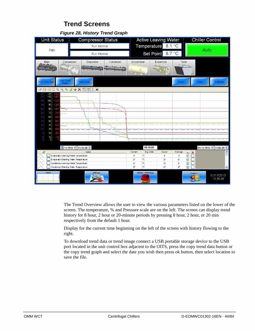
OMM WCT Centrifugal Chillers D-EOMWC01302-16EN - 44/84
Trend Screens
Figure 28, History Trend Graph
The Trend Overview allows the user to view the various parameters listed on the lower of the
screen. The temperature, % and Pressure scale are on the left. The screen can display trend
history for 8 hour, 2 hour or 20-minute periods by pressing 8 hour, 2 hour, or 20 min
respectively from the default 1 hour.
Display for the current time beginning on the left of the screen with history flowing to the
right.
To download trend data or trend image connect a USB portable storage device to the USB
port located in the unit control box adjacent to the OITS, press the copy trend data button or
the copy trend graph and select the date you wish then press ok button, then select location to
save the file.

OMM WCT Centrifugal Chillers D-EOMWC01302-16EN - 45/84
Figure 29, Alarm History
The Alarm History lists the alarms with the most current on top with date stamp, action taken and the
cause of the alarm.
This screen is also used to download the Alarm History shown above. To download alarm history
connect a USB portable storage device to the USB port located in the unit control box adjacent to the
OITS, press the copy alarm data button, then select location to save the file.

OMM WCT Centrifugal Chillers D-EOMWC01302-16EN - 46/84
ACTIVE ALARM Screen
Figure 30, Active Alarms
The Active Alarm screen is accessible when an active alarm exists on the unit by pressing the animated
red alarm signal on any screen.
Alarms are arranged in order of occurrence, with the most recent on top. Once the abnormal condition
is corrected, pressing the "Clear Alarm" button will clear the alarm.
The current active alarms (there may be more than one) are displayed.
The date/time and cause of the alarm are displayed.
This screen is also used to download the Active Alarm shown above. To download active alarm connect a
USB portable storage device to the USB port located in the unit control box adjacent to the OITS, press
the copy alarm data button, then select location to save the file.
Clearing Alarms After eliminating the cause of the alarm, clear the alarm by pressing the clear alarm button. This will
clear the alarm from the register and allow the unit to restart after going through the start sequence. The
alarm notice will be deleted from the screen.
However, if the cause of the alarm is not remedied, the alarm is still active and the alarm message will
remain on screen. The unit will not begin its starting sequence.
Always remedy the cause of an alarm before attempted to clear it.
Alarms fall into three distinct categories: Faults, Problems, and Warnings as detailed in the following
section.
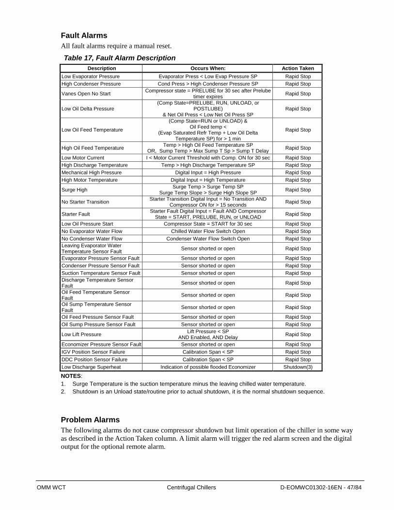
OMM WCT Centrifugal Chillers D-EOMWC01302-16EN - 47/84
Fault Alarms
All fault alarms require a manual reset.
Table 17, Fault Alarm Description
Description Occurs When: Action Taken
Low Evaporator Pressure Evaporator Press < Low Evap Pressure SP Rapid Stop
High Condenser Pressure Cond Press > High Condenser Pressure SP Rapid Stop
Vanes Open No Start Compressor state = PRELUBE for 30 sec after Prelube
timer expires Rapid Stop
Low Oil Delta Pressure (Comp State=PRELUBE, RUN, UNLOAD, or
POSTLUBE) & Net Oil Press < Low Net Oil Press SP
Rapid Stop
Low Oil Feed Temperature
(Comp State=RUN or UNLOAD) & Oil Feed temp <
(Evap Saturated Refr Temp + Low Oil Delta Temperature SP) for > 1 min
Rapid Stop
High Oil Feed Temperature Temp > High Oil Feed Temperature SP
OR, Sump Temp > Max Sump T Sp > Sump T Delay Rapid Stop
Low Motor Current I < Motor Current Threshold with Comp. ON for 30 sec Rapid Stop
High Discharge Temperature Temp > High Discharge Temperature SP Rapid Stop
Mechanical High Pressure Digital Input = High Pressure Rapid Stop
High Motor Temperature Digital Input = High Temperature Rapid Stop
Surge High Surge Temp > Surge Temp SP
Surge Temp Slope > Surge High Slope SP Rapid Stop
No Starter Transition Starter Transition Digital Input = No Transition AND
Compressor ON for > 15 seconds Rapid Stop
Starter Fault Starter Fault Digital Input = Fault AND Compressor
State = START, PRELUBE, RUN, or UNLOAD Rapid Stop
Low Oil Pressure Start Compressor State = START for 30 sec Rapid Stop
No Evaporator Water Flow Chilled Water Flow Switch Open Rapid Stop
No Condenser Water Flow Condenser Water Flow Switch Open Rapid Stop
Leaving Evaporator Water Temperature Sensor Fault
Sensor shorted or open Rapid Stop
Evaporator Pressure Sensor Fault Sensor shorted or open Rapid Stop
Condenser Pressure Sensor Fault Sensor shorted or open Rapid Stop
Suction Temperature Sensor Fault Sensor shorted or open Rapid Stop
Discharge Temperature Sensor Fault
Sensor shorted or open Rapid Stop
Oil Feed Temperature Sensor Fault
Sensor shorted or open Rapid Stop
Oil Sump Temperature Sensor Fault
Sensor shorted or open Rapid Stop
Oil Feed Pressure Sensor Fault Sensor shorted or open Rapid Stop
Oil Sump Pressure Sensor Fault Sensor shorted or open Rapid Stop
Low Lift Pressure Lift Pressure < SP
AND Enabled, AND Delay Rapid Stop
Economizer Pressure Sensor Fault Sensor shorted or open Rapid Stop
IGV Position Sensor Failure Calibration Span < SP Rapid Stop
DDC Position Sensor Failure Calibration Span < SP Rapid Stop
Low Discharge Superheat Indication of possible flooded Economizer Shutdown(3)
NOTES:
1. Surge Temperature is the suction temperature minus the leaving chilled water temperature.
2. Shutdown is an Unload state/routine prior to actual shutdown, it is the normal shutdown sequence.
Problem Alarms
The following alarms do not cause compressor shutdown but limit operation of the chiller in some way
as described in the Action Taken column. A limit alarm will trigger the red alarm screen and the digital
output for the optional remote alarm.
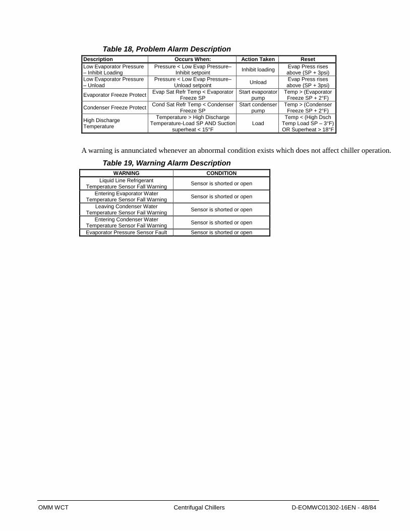
OMM WCT Centrifugal Chillers D-EOMWC01302-16EN - 48/84
Table 18, Problem Alarm Description
Description Occurs When: Action Taken Reset
Low Evaporator Pressure – Inhibit Loading
Pressure < Low Evap Pressure–Inhibit setpoint
Inhibit loading Evap Press rises above (SP + 3psi)
Low Evaporator Pressure – Unload
Pressure < Low Evap Pressure–Unload setpoint
Unload Evap Press rises above (SP + 3psi)
Evaporator Freeze Protect Evap Sat Refr Temp < Evaporator
Freeze SP Start evaporator
pump Temp > (Evaporator
Freeze SP + 2°F)
Condenser Freeze Protect Cond Sat Refr Temp < Condenser
Freeze SP Start condenser
pump Temp > (Condenser
Freeze SP + 2°F)
High Discharge Temperature
Temperature > High Discharge Temperature-Load SP AND Suction
superheat < 15°F Load
Temp < (High Dsch Temp Load SP – 3°F) OR Superheat > 18°F
A warning is annunciated whenever an abnormal condition exists which does not affect chiller operation.
Table 19, Warning Alarm Description
WARNING CONDITION
Liquid Line Refrigerant Temperature Sensor Fall Warning
Sensor is shorted or open
Entering Evaporator Water Temperature Sensor Fall Warning
Sensor is shorted or open
Leaving Condenser Water Temperature Sensor Fail Warning
Sensor is shorted or open
Entering Condenser Water Temperature Sensor Fail Warning
Sensor is shorted or open
Evaporator Pressure Sensor Fault Sensor is shorted or open

OMM WCT Centrifugal Chillers D-EOMWC01302-16EN - 49/84
Using the Controller
Figure 31, Display and Keypad Layout
The keypad/display consists of a 5-line by 22-character display, three buttons (keys) and a
“push and roll” navigation wheel. There is an Alarm Button, Menu (Home) Button, and a
Back Button. The wheel is used to navigate between lines on a screen (page) and to increase
and decrease changeable values when editing. Pushing the wheel acts as an Enter Button and
will jump from a link to the next set of parameters.
Figure 32, Typical Screen
6 View/Set Unit 3
Status/Settings
Set Up
Temperature
Date/Time/Schedule Generally, each line on the display contains a menu title, a parameter (such as a value or a
setpoint), or a link (which will have an arrow in the right of the line) to a further menu.
The first line visible on each display includes the menu title and the line number to which the
cursor is currently “pointing”, in the above case 3, Temperature.
The left most position of the title line includes an “up” arrow ▲ to indicate there are lines
(parameters) “above” the currently displayed line; and/or a “down” arrow ▼ to indicate there
are lines (parameters) “below” the currently displayed items or an “up/down” arrow to
indicate there are lines “above and below” the currently displayed line. The selected line is
highlighted.
Each line on a screen can contain status-only information or include changeable data fields
(setpoints).
When the cursor is on a line the highlights will look like this:
If line contains a changeable value-
If the line contains status-only
information-
Or a line in a menu may be a link to further menus. This is often referred to as a jump line,
meaning pushing the navigation wheel will cause a “jump” to a new menu. An arrow ()is
Evaporator Delta T= 10.0F
Unit Status= Run
Navigation wheel
Back
Display
Home

OMM WCT Centrifugal Chillers D-EOMWC01302-16EN - 50/84
displayed to the far right of the line to indicate it is a “jump” line and the entire line is
highlighted when the cursor is on that line.
NOTE - Only menus and items that are applicable to the specific unit configuration are
displayed.
This manual includes information relative to the operator level of parameters; data and
setpoints necessary for the everyday operation of the chiller. There are more extensive
menus available for the use of service technicians.
Navigating When power is applied to the control circuit, the controller screen will be active and display the
Home screen, which can also be accessed by pressing the Menu Button The navigating wheel is the
only navigating device necessary, although the MENU, ALARM, and BACK buttons can provide
shortcuts as explained later.
Passwords Enter passwords from the Main Menu:
Enter Password, links to the Entry screen, which is an editable screen so pressing the
wheel goes to the edit mode where the password (5321) can be entered. The first (*) will
be highlighted, rotate the wheel clockwise to the first number and set it by pressing the
wheel. Repeat for the remaining three numbers.
The password will time out after 10 minutes, and is cancelled if a new password is
entered or the control powers down.
Not entering a password allows access to a limited number of parameters with asterisks.
Figure 33, Password Menu
Main Menu
1/3 Enter Password
Unit Status
Off: Unit Sw
ACTIVE SETPT 44.6F
Figure 34, Password Entry Page
Enter Password
1/1 Enter PW ****
Entering an invalid password has the same effect as not entering a password.
Once a valid password has been entered, the controller allows further changes and access
without requiring the user to enter a password until either the password timer expires or a
different password is entered. The default value for this password timer is 10 minutes.
Navigation Mode
When the navigation wheel is turned clockwise, the cursor moves to the next line (down) on
the page. When the wheel is turned counter-clockwise the cursor moves to the previous line

OMM WCT Centrifugal Chillers D-EOMWC01302-16EN - 51/84
(up) on the page. The faster the wheel is turned the faster the cursor moves. Pushing the
wheel acts as an “Enter” button.
Three types of lines exist:
Menu title, displayed in the first line as in Figure .
Link (also called Jump) having an arrow ( ) in the right of the line and used to link to
the next menu.
Parameters with a value or adjustable setpoint.
For example, “Time Until Restart” jumps from level 1 to level 2 and stops there.
When the Back Button is pressed the display reverts back to the previously displayed page. If
the Back button is repeatedly pressed the display continues to revert one page back along the
current navigation path until the “main menu” is reached.
When the Menu (Home) Button is pressed the display reverts to the “main page.”
When the Alarm Button is depressed, the Alarm Lists menu is displayed.
Edit Mode
The Editing Mode is entered by pressing the navigation wheel while the cursor is pointing to
a line containing an editable field. Once in the edit mode pressing the wheel again causes the
editable field to be highlighted. Turning the wheel clockwise while the editable field is
highlighted causes the value to be increased. Turning the wheel counter-clockwise while the
editable field is highlighted causes the value to be decreased. The faster the wheel is turned
the faster the value is increased or decreased. Pressing the wheel again cause the new value
to be saved and the keypad/display to leave the edit mode and return to the navigation mode.
A parameter with an “R” is read only; it is giving a value or description of a condition. An
“R/W indicates a read and/or write opportunity; a value can be read or changed (providing
the proper password has been entered).
Example 1: Check Status, for example -is the unit being controlled locally or by an external
network? We are looking for the Unit Control Source since this is a unit status parameter, start at
Main Menu and select View/Set Unit and press the wheel to jump to the next set of menus. There
will be an arrow at the right side of the box, indicating that a jump to the next level is required. Press
the wheel to execute the jump.
You will arrive at the Status/ Settings link. There is an arrow indicating that this line is a link to a
further menu. Press the wheel again to jump to the next menu, Unit Status/Settings.
Rotate the wheel to scroll down to Control Source and read the result.
Example 2; Change a Setpoint, the chilled water setpoint for example. This parameter is designated
as Cool LWT setpoint and is a unit parameter. From the Main Menu select View/Set Unit. The arrow
indicated that this is link to a further menu.
Press the wheel and jump to the next menu View/Set Unit and use the wheel to scroll down to
Temperatures. This again has an arrow and is a link to a further menu. Press the wheel and jump to
the Temperatures menu, which contains temperatures values and setpoints. The first line is Evap
LWT, rotate wheel until Cool LWT is highlighted. Press the wheel to enter edit mode. Rotate wheel
until new setpoint is reached, then press wheel to accept the new value and exit edit mode.
Example 3; Clear an Alarm, from the Main Menu scroll down to the Alarms line. Note the arrow
indicating this line is a link. Press the wheel to jump to the next menu Alarms There are two lines
here; Alarm Active and Alarm Log. Alarms are cleared from the Active Alarm link. Press the wheel

OMM WCT Centrifugal Chillers D-EOMWC01302-16EN - 52/84
to jump to the next screen. With the first line highlighted, press the wheel to enter edit mode. Rotate
wheel until AlmClr is set to On, then press wheel to clear the alarms.
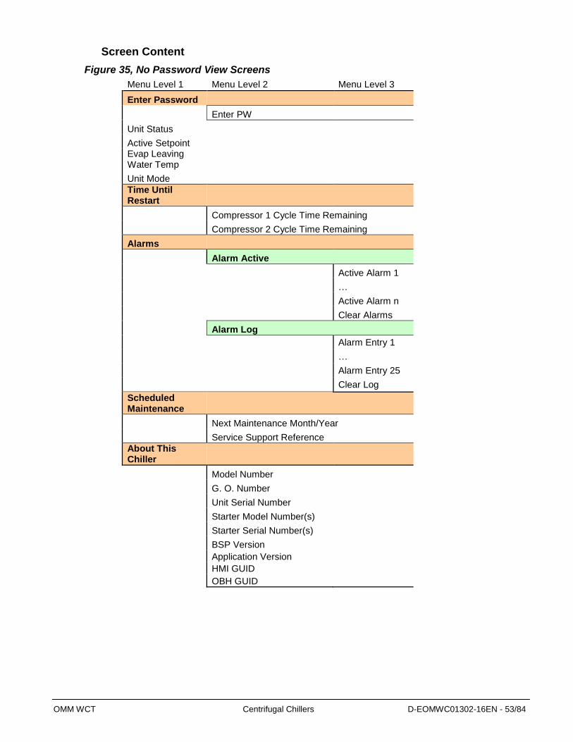
OMM WCT Centrifugal Chillers D-EOMWC01302-16EN - 53/84
Screen Content
Figure 35, No Password View Screens
Menu Level 1 Menu Level 2 Menu Level 3
Enter Password
Enter PW
Unit Status Active Setpoint Evap Leaving
Water Temp Unit Mode Time Until
Restart
Compressor 1 Cycle Time Remaining
Compressor 2 Cycle Time Remaining
Alarms
Alarm Active
Active Alarm 1
…
Active Alarm n
Clear Alarms
Alarm Log
Alarm Entry 1
…
Alarm Entry 25
Clear Log
Scheduled Maintenance
Next Maintenance Month/Year
Service Support Reference About This
Chiller
Model Number
G. O. Number
Unit Serial Number
Starter Model Number(s)
Starter Serial Number(s)
BSP Version
Application Version
HMI GUID
OBH GUID

OMM WCT Centrifugal Chillers D-EOMWC01302-16EN - 54/84
Figure 36, Operator View Screen
Menu Level 1 Menu Level 2 Menu Level 3 Menu Level 4
Enter Password
Quick Menu
View/Set Unit
Status/Settings
Set-Up
Temperatures
Date/Time/Schedules
Power Conservation
Alarm Limits
Ctrlr IP Setup
Design Conditions
Menu Password
View/Set Circuit
Circuit #1
Circuit #2
Data
Compressor 1
Data
Motor
Oil Sump
Exv
Unit Status Active Setpoint
Evap Leaving Water Temp Unit Mode
Time Until Restart
Alarms
Alarm Active
Alarm Log
Event Log
Unit Power Restore
Circuit #1
Circuit #2
Scheduled Maintenance
About This Chiller
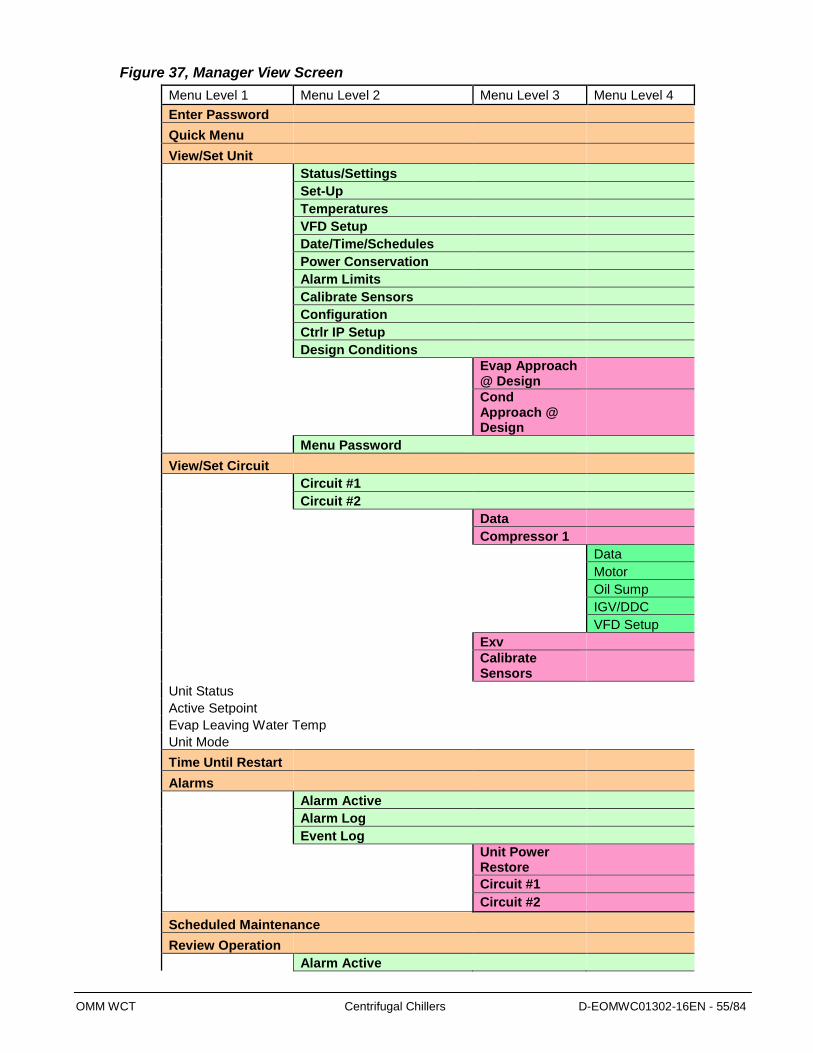
OMM WCT Centrifugal Chillers D-EOMWC01302-16EN - 55/84
Figure 37, Manager View Screen
Menu Level 1 Menu Level 2 Menu Level 3 Menu Level 4
Enter Password
Quick Menu
View/Set Unit
Status/Settings
Set-Up
Temperatures
VFD Setup
Date/Time/Schedules
Power Conservation
Alarm Limits
Calibrate Sensors
Configuration
Ctrlr IP Setup
Design Conditions
Evap Approach @ Design
Cond Approach @ Design
Menu Password
View/Set Circuit
Circuit #1
Circuit #2
Data
Compressor 1
Data
Motor
Oil Sump
IGV/DDC
VFD Setup
Exv
Calibrate Sensors
Unit Status Active Setpoint Evap Leaving Water Temp
Unit Mode Time Until Restart
Alarms
Alarm Active
Alarm Log
Event Log
Unit Power Restore
Circuit #1
Circuit #2
Scheduled Maintenance
Review Operation
Alarm Active
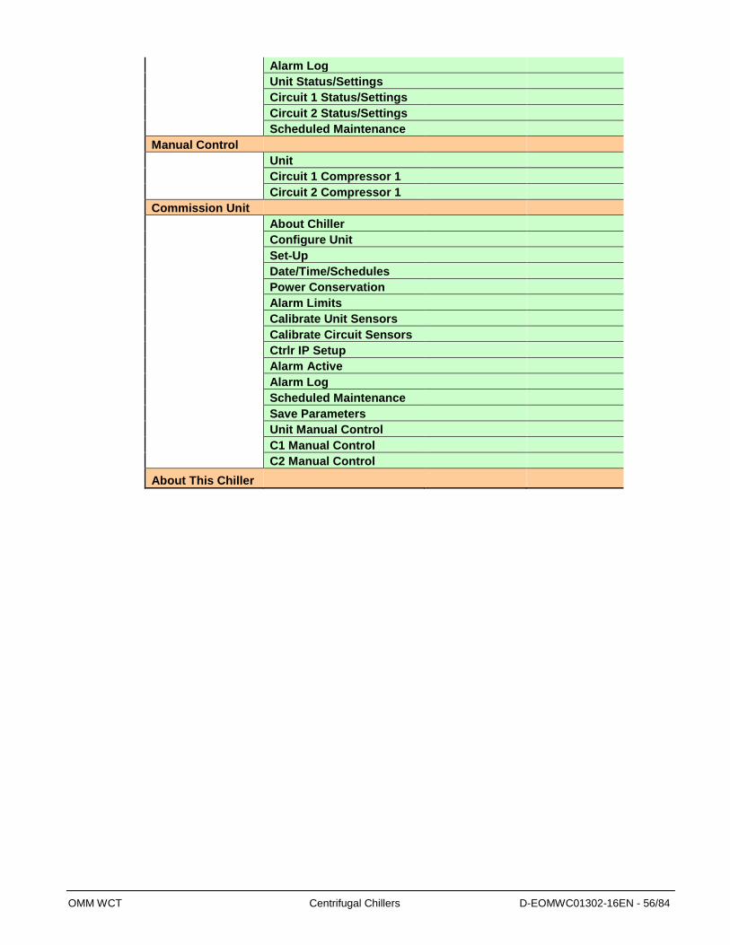
OMM WCT Centrifugal Chillers D-EOMWC01302-16EN - 56/84
Alarm Log
Unit Status/Settings
Circuit 1 Status/Settings
Circuit 2 Status/Settings
Scheduled Maintenance
Manual Control
Unit
Circuit 1 Compressor 1
Circuit 2 Compressor 1
Commission Unit
About Chiller
Configure Unit
Set-Up
Date/Time/Schedules
Power Conservation
Alarm Limits
Calibrate Unit Sensors
Calibrate Circuit Sensors
Ctrlr IP Setup
Alarm Active
Alarm Log
Scheduled Maintenance
Save Parameters
Unit Manual Control
C1 Manual Control
C2 Manual Control
About This Chiller

OMM WCT Centrifugal Chillers D-EOMWC01302-16EN - 57/84
Setpoints
Table 20, Unit Setpoints
Description Default Range Password
Unit
Unit Enable OFF OFF, ON O
Number of Cir 2 1 to 2 T
Number of Comp 2 1 to 2
Pbus Address
Unit Mode COOL COOL, ICE, HEAT, TEST O
Available Modes COOL Cool, Cool w/Glycol, Cool/Ice, Ice, Cool/Heat, Heat
T
Control Source Local LOCAL, Network, Inputs O
Display Units °C/kPa °C/kPa, °F/psi O
Alarm Output All Alarm Alarms, Safety Only
Lift Factor 0.09 0.00 to 2.00
External Fault Input 0
Cool LWT 44. 0°F 35.0 to 80.0 °F O
Ice LWT 25. 0°F 15.0 to 35.0 °F O
Heat LWT 135. 0°F 100.0 to 150.0 °F O
Startup Delta T 3.0°F 0.0 to 10.0 °F O
Shutdown Delta T 3.0°F 0.0 to 3.0 °F O
LWT Reset Type NONE NONE, RETURN, 4-20mA M
Max Reset Delta T 0.0°F 0.0 to 20.0 °F M
Start Reset Delta T 10. 0°F 0.0 to 20.0 °F M
Evap Recirculate 30 sec 0.2 to 5 min M
Evap Pump Control Pump #1 Only Pump #1 Only, Pump #2 Only, Auto Lead, #1 Primary, #2 Primary
M
Cond Pump Control Pump #1 Only Pump #1 Only, Pump #2 Only, Auto Lead, #1 Primary, #2 Primary
M
Maximum Pull down Rate 0.5 °F/min 0.1 to 5.0 °F/min M
Minimum Pull down Rate 0.1 °F/min 0.0 to 5.0 °F/min M
Maximum Compressor Run 1 1 to 16 M
Stage Delta T 1 0.5-5.0 M
Language ENGLISH ENGLISH, O
Unit Offset
Evap LWT Offset 0 -5 to 5 °C
Evap EWT Offset 0 -5 to 5 °C
Cond LWT Offset 0 -5 to 5 °C
Cond EWT Offset 0 -5 to 5 °C
Continued next page.

OMM WCT Centrifugal Chillers D-EOMWC01302-16EN - 58/84
Description Default Range Password
Global Circuit
Electronic Expansion Valve
Exv Control Cond Delta T Cond Delta T, Evap Delta T
SH Drop out 55.5 ∆°C 0 to 55.5 ∆°C M
WCC Cap Ratio 0.6 0.45 to 0.70
Timers
Start-Start 40 min 15 to 60 min M
Stop-Start 3 min 3 to 20 min M
Prelube Timer 30 sec 10 to 240 sce
Unload Timer 60 sec 10 to 240 sec T
Postlube Timer 300 sec 10 to 360 sec T
Full Load Delay 10 sec 5 to 60 sec
Load Cycle Time 30 sec 150 to 60 sec
Unload Cycle Time 30 sec 150 to 60 sec
Oil Sump Delay 10 sec 0 to 60 sec
Motor Amps
Demand Limit Enable OFF OFF, ON O
Demand Limit Minimum Amps 40% 5 to 80% T
Demand Limit Maximum Amps 100% 10 to 100% T
Soft Load Enable OFF OFF, ON M
Begin Amp Limit 40 10 to 100% M
Nameplate RLA 0.0 Amps 0.0 to 2000 Amps
Soft Load Ramp Time 5 min 1 to 60 min M
Stage Down RLA 60% 0.0 to 99.0%
Db Adjustment 0.0 0.0 to 0.3 ∆°C
Capacity Balance 10.0 2 to 18
Lead Unload Rate 6.0 2 to 18
Balance Mode Local Unit Local Unit, Network Unit, Alternative
Motor RLA Input Type 0-5V 0-5V, 0-10V, 4-20mA
Motor RLA Maximum 125% 0.0 to 500%
Staging
Comp Stage Mode Normal Normal, Efficiency, Pump, Standby
M
Absolute Capacity 100T 0 to 9999 T
Alarms
Low Discharge Superheat 3 °C 0.0 to 6.0 °C
Evaporator Freeze 34.0 °F -9.0 to 45.0 °F T
Condenser Freeze 34.0 °F -9.0 to 45.0 °F T
Low Pressure Alarm 28 psi 5 to 45 psi T
Low Pressure Hold 33 psi 7 to 45 psi T
Low Pressure Unload 31 psi 6 to 45 psi T
Continued next page.

OMM WCT Centrifugal Chillers D-EOMWC01302-16EN - 59/84
Description Default Range Password
High Discharge Temperature Alarm 194 °F 120 to 240 °F T
High Discharge Temperature Load 170 °F 120 to 240 °F T
High Pressure Alarm 140 psi 120 to 240 psi T
Minimum RLA 40% 5 to 80 %
Oil No Start Delta Temperature 22.2 °C 16.6 to 33.4°C T
Maximum Oil Feed Temperature 140 °F 0 to 212 °F T
Minimum Oil Feed Delta Temperature
16.7 °C 0 to 44.5 °C T
Low Net Oil Pressure 22 psi 0 to 76 psi T
Maximum Surge Slope 11.1 °C/min 0.5 to 55 °C/min T
Surge Delta Temperature 3.3 °C 1.1 to 13.9 °C T
Low Lift Pressure 14.0 psi 0 to 73.0 psi T
Minimum Oil Sump Temperature 104°F 0 to 120°F T
Maximum Oil Sump Temperature 158°F 0 to 212°F T
Vanes Calibration Time 8 hrs 0.3 to 24 hrs
VFD
VFD Enable No No, Yes T
VFD Minimum Speed 70 70 to 100% T
Speed @ 0 Lift 50 0 to 100% T
Lift @ 100% Speed 22.2∆°C 16.7 to 33.3 ∆°C T
VFD Update 4 sec 1 to 20 sec
VFD Output Type 4-20mA 4-20mA, 0-10Vdc
Circuit
Exv Gain 1 0.25 to 4.0
Exv Offset 700.0 100.0 to 2000.0
Exv SC Ratio 110.0 80.0 to 250.0
Exv Offset Target 0.0 -9.0 to 9.0
Exv Superheat Enable True True, False
Exv Error Gain 0.9 0.1 to 2.0
Exv Mode Auto Auto, Manual
Exv Offset Bdi 50.0 2.0 to 500.0
Exv Offset Bdd 100.0 2 .0 to 500.0
Exv Offset Kd 25.0 -32.0 to 32.0
Exv AOC Range 20.0 5.0 to 100.0
Exv Manual Position 5.0 0.0 to 100.0
Evaporator Pressure Offset 0.0 -100.0 to 100.0
Condenser Pressure Offset 0.0 -100.0 to 100.0
Liquid Line Temp Offset 0.0 -5.0 to 5
Compressor
Comp Stage Sequence # 1 1,2, … (# of Compressors) M
Vane Manual Mode 0
Continued next page.
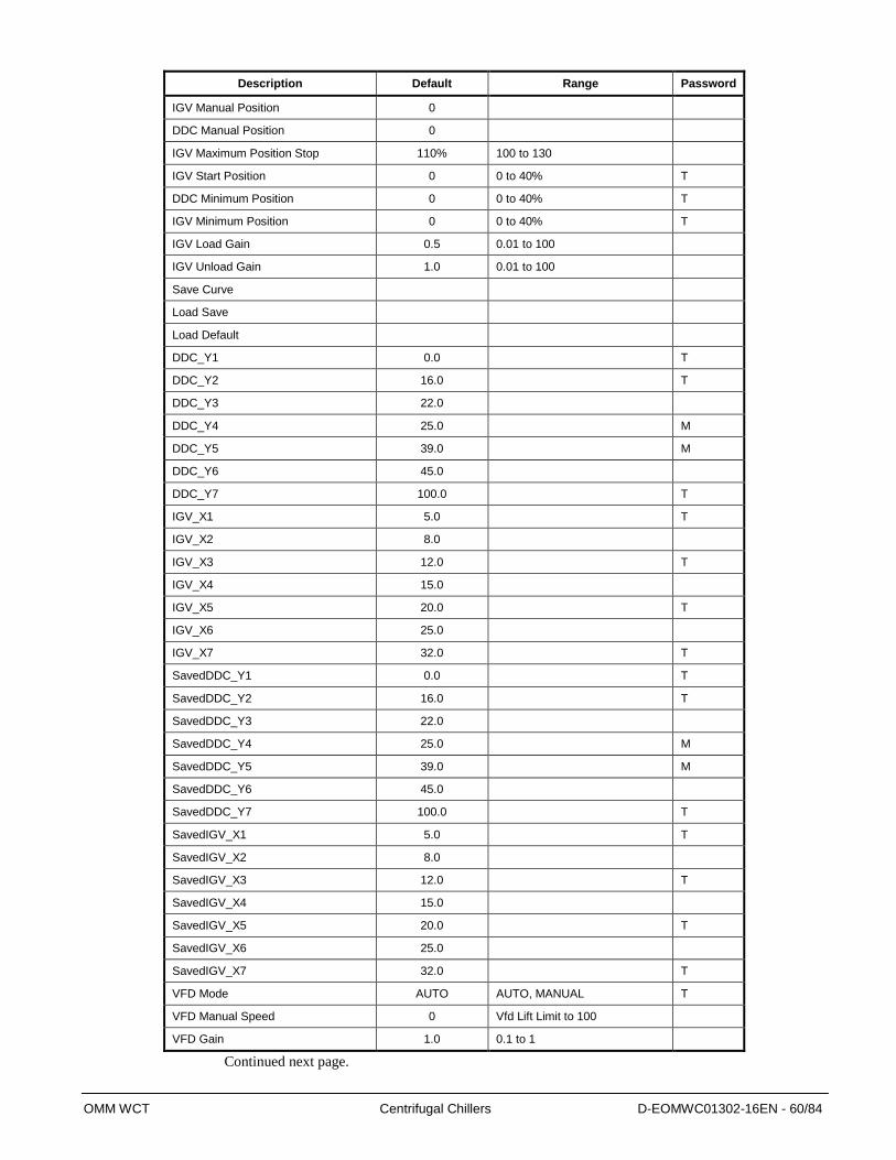
OMM WCT Centrifugal Chillers D-EOMWC01302-16EN - 60/84
Description Default Range Password
IGV Manual Position 0
DDC Manual Position 0
IGV Maximum Position Stop 110% 100 to 130
IGV Start Position 0 0 to 40% T
DDC Minimum Position 0 0 to 40% T
IGV Minimum Position 0 0 to 40% T
IGV Load Gain 0.5 0.01 to 100
IGV Unload Gain 1.0 0.01 to 100
Save Curve
Load Save
Load Default
DDC_Y1 0.0
T
DDC_Y2 16.0
T
DDC_Y3 22.0
DDC_Y4 25.0
M
DDC_Y5 39.0
M
DDC_Y6 45.0
DDC_Y7 100.0
T
IGV_X1 5.0
T
IGV_X2 8.0
IGV_X3 12.0
T
IGV_X4 15.0
IGV_X5 20.0
T
IGV_X6 25.0
IGV_X7 32.0
T
SavedDDC_Y1 0.0
T
SavedDDC_Y2 16.0
T
SavedDDC_Y3 22.0
SavedDDC_Y4 25.0
M
SavedDDC_Y5 39.0
M
SavedDDC_Y6 45.0
SavedDDC_Y7 100.0
T
SavedIGV_X1 5.0
T
SavedIGV_X2 8.0
SavedIGV_X3 12.0
T
SavedIGV_X4 15.0
SavedIGV_X5 20.0
T
SavedIGV_X6 25.0
SavedIGV_X7 32.0
T
VFD Mode AUTO AUTO, MANUAL T
VFD Manual Speed 0 Vfd Lift Limit to 100
VFD Gain 1.0 0.1 to 1
Continued next page.

OMM WCT Centrifugal Chillers D-EOMWC01302-16EN - 61/84
Description Default Range Password
Suction Temp Offset 0.0 -5.0 to 5.0
Discharge Temp Offset 0.0 -5.0 to 5.0
Oil Feed Temp Offset 0.0 -5.0 to 5.0
Oil Sump Temp Offset 0.0 -5.0 to 5.0
Econ Press Offset 0.0 -100.0 to 100
Oil Feed Press Offset 0.0 -100.0 to 100
Oil Sump Press Offset 0.0 -100.0 to 100
Cooling Tower
Tower Control None None, Temperature, Lift M
Tower Stages 2 1 to 4 M
Tower Stage Up Time 2 min 1 to 60 min M
Tower Stage Down Time 5 min 1 to 60 min M
Tower Stage Differential Temp 1.7 °C 0.6 to 5.6 °C M
Tower Stage On Temp #1 70 °F 40 to 120 °F M
Tower Stage On Temp #2 75 °F 40 to 120 °F M
Tower Stage On Temp #3 80 °F 40 to 120 °F M
Tower Stage On Temp #4 85 °F 40 to 120 °F M
Tower Valve Setpoint Temp 18.3 4.4 to 48.9 °C
Tower Valve Db Temp 1.1 0.6 to 5.6 °C
Tower Stage Differential Press 6.0 psi 1.0 to 20.0 psi M
Tower Stage On Lift #1 35 psi 10 to 130 psi M
Tower Stage On Lift #2 45 psi 10 to 130 psi M
Tower Stage On Lift #3 55 psi 10 to 130 psi M
Tower Stage On Lift #4 65 psi 10 to 130 psi M
Tower Valve Setpoint Lift 207.0 69.0 to 897.0 kPa
Tower Valve Db Lift 14.0 7.0 to 138.0 kPa
Tower Valve/VFD Control None None, Valve Setpoint, Valve Stage, VFD Stage, Valve SP/VFD Stage
M
Tower Valve Setpoint Temp 65 °F 40 to 120 °F M
Tower Valve Setpoint Lift 30 psi 10 to 130 psi M
Tower Valve Deadband Temp 2.0 °F 1.0 to 10.0 °F M
Tower Valve Deadband Lift 4.0 psi 1.0 to 20.0 psi M
Tower Stage Down @ 20 0 to 100% M
Tower Stage Up @ 80 0 to 100% M
Tower Valve Minimum Range 10 0 to 100% M
Tower Valve Maximum Range 90 0 to 100% M
Tower Valve Type NC NC, NO M
Tower Valve Minimum Start Position 0 0 to 100% M
Tower Valve Minimum Position Temp 60 °F 0 to 100 °F M
Tower Valve Maximum Start Position 10 0 to 100% M
Tower Valve Maximum Position Temp
90 °F 0 to 100 °F M
Tower Valve Error Gain 25 10 to 99 M
Tower Valve Slope Gain 25 10 to 99 M

OMM WCT Centrifugal Chillers D-EOMWC01302-16EN - 62/84
Condenser Water
Cooling towers used with Daikin centrifugal chillers are normally selected for maximum condenser
inlet water temperatures between 75°F and 90°F (24°C and 32°C). Lower entering water temperatures
are desirable from the standpoint of energy reduction, but a minimum does exist.
When the ambient wet bulb temperature is lower than design, the condenser water temperature can be
allowed to fall. The resultant lower condensing temperature will improve chiller performance.
WCT chillers are equipped with electronic expansion valves (EEV) and will operate with entering
condenser water temperatures as low as calculated by the following equation and shown in the chart
following.
Note: Provisions or modifications need to be made in the event of inverted starts (condenser water
colder than chilled water). For example, 3 way bypass valve controlled by the chiller, or tower
controls.
Min. ECWT = 10.973 + LCHWT – 0.17 * CHWDTFL(PLD/100) + 8 * (PLD/100)2
ECWT = Entering condenser water temperature
LCHWT = Leaving chilled water temperature
CHWDTFL = Chilled Water Delta-T at full load
PLD = The percent chiller load point to be checked
Figure 38, Minimum Operating Entering Condenser Water Temperature (10 Range)
Note : Some limitation in control may apply when operating chiller in the condition that
ECWT is same or above but still around minimum ECWT
45.00
50.00
55.00
60.00
65.00
70.00
0 10 20 30 40 50 60 70 80 90 100 110
Percent Load
EC
WT
, (F
)
46.0 F LCHWT44.6 F LCHWT44.0 F LCHWT42.0 F LCHWT

OMM WCT Centrifugal Chillers D-EOMWC01302-16EN - 63/84
For example; at 44F LCHWT, 10-degree F chilled water Delta-T, and 50% full load operation, the
entering condenser water temperature could be as low as 56 F.
The operating strategy for cooling tower fans requires some analysis. Regardless of power
consumption considerations, the minimum allowable entering condenser water temperature must
be maintained.
Depending on local climatic conditions, using the lowest possible entering condenser water
temperature may be more costly in total system power consumed than the expected savings in
chiller power would suggest, due to the excessive fan power required.
Even with tower fan control, some form of water flow control, such as tower bypass, is
recommended and is required if fan control alone will not maintain minimum water temperatures.
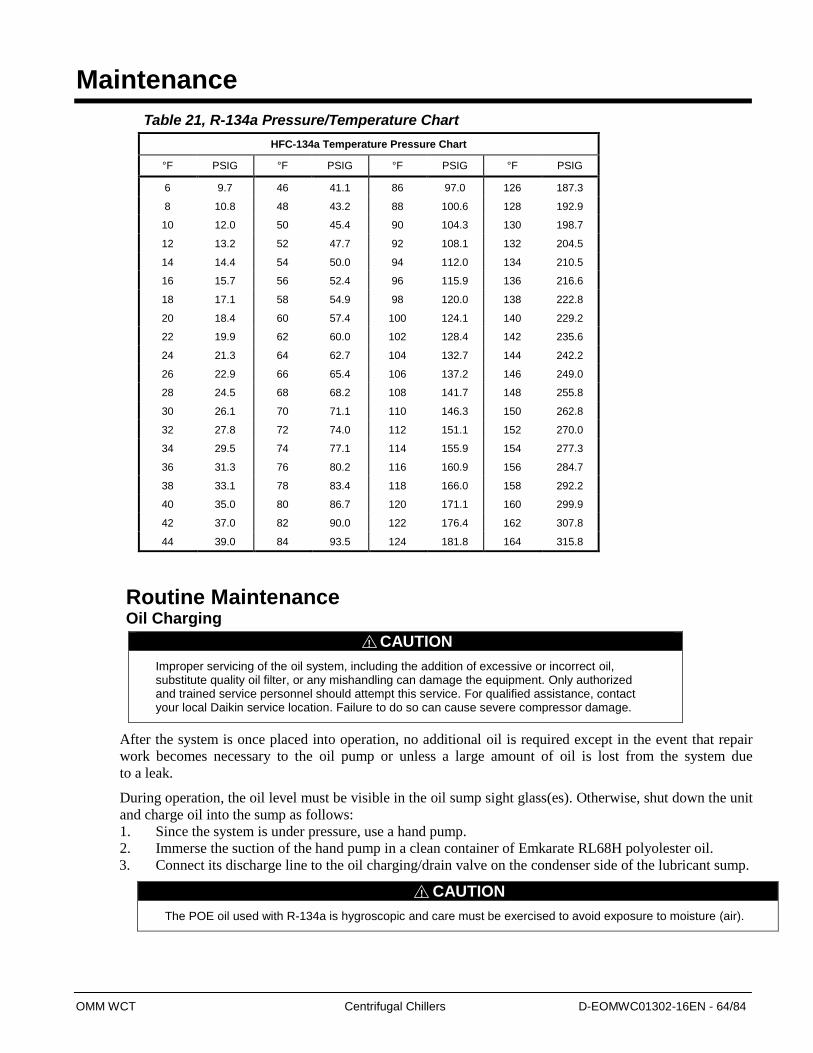
OMM WCT Centrifugal Chillers D-EOMWC01302-16EN - 64/84
Maintenance
Table 21, R-134a Pressure/Temperature Chart
HFC-134a Temperature Pressure Chart
°F PSIG °F PSIG °F PSIG °F PSIG
6 9.7 46 41.1 86 97.0 126 187.3
8 10.8 48 43.2 88 100.6 128 192.9
10 12.0 50 45.4 90 104.3 130 198.7
12 13.2 52 47.7 92 108.1 132 204.5
14 14.4 54 50.0 94 112.0 134 210.5
16 15.7 56 52.4 96 115.9 136 216.6
18 17.1 58 54.9 98 120.0 138 222.8
20 18.4 60 57.4 100 124.1 140 229.2
22 19.9 62 60.0 102 128.4 142 235.6
24 21.3 64 62.7 104 132.7 144 242.2
26 22.9 66 65.4 106 137.2 146 249.0
28 24.5 68 68.2 108 141.7 148 255.8
30 26.1 70 71.1 110 146.3 150 262.8
32 27.8 72 74.0 112 151.1 152 270.0
34 29.5 74 77.1 114 155.9 154 277.3
36 31.3 76 80.2 116 160.9 156 284.7
38 33.1 78 83.4 118 166.0 158 292.2
40 35.0 80 86.7 120 171.1 160 299.9
42 37.0 82 90.0 122 176.4 162 307.8
44 39.0 84 93.5 124 181.8 164 315.8
Routine Maintenance Oil Charging
CAUTION
Improper servicing of the oil system, including the addition of excessive or incorrect oil, substitute quality oil filter, or any mishandling can damage the equipment. Only authorized and trained service personnel should attempt this service. For qualified assistance, contact your local Daikin service location. Failure to do so can cause severe compressor damage.
After the system is once placed into operation, no additional oil is required except in the event that repair
work becomes necessary to the oil pump or unless a large amount of oil is lost from the system due
to a leak.
During operation, the oil level must be visible in the oil sump sight glass(es). Otherwise, shut down the unit
and charge oil into the sump as follows:
1. Since the system is under pressure, use a hand pump.
2. Immerse the suction of the hand pump in a clean container of Emkarate RL68H polyolester oil.
3. Connect its discharge line to the oil charging/drain valve on the condenser side of the lubricant sump.
CAUTION
The POE oil used with R-134a is hygroscopic and care must be exercised to avoid exposure to moisture (air).
!
!

OMM WCT Centrifugal Chillers D-EOMWC01302-16EN - 65/84
4. Pump a few strokes of the oil to fill the connection line with oil to purge air just before tightening
the connection at the charging valve.
5. Open the sump charging valve and bring the oil level to be visible on the sight glass.
6. Close the charging valve while the oil pump is still connected.
7. Manually start the oil pump to fill the oil lines, oil cooler and oil filter to check the “true” lubricant
level since this will lower the oil level in the sump.
8. If it is necessary to make up the lost oil in the lines then shut down the oil pump and repeat steps 5
through 7.
9. After oil charging is completed and if the oil is visible on the sight glass(es) while the oil pump is
operating, shut down the oil pump and disconnect the hand pump.
CAUTION
The oil heater should be immersed in oil all the time it is energized. Therefore, as a caution de-energize the oil heater during the oil charging process to minimize the possibility of damage to the oil heater.
CAUTION
When the machine is operated again, and on a regular basis during operation, the oil level must be checked to determine if oil needs to be added to maintain the proper operating level. Failure to do so can cause compressor damage.
Oil Analysis
The condition of compressor oil can be an indication of the general condition of the refrigerant circuit
and compressor wear. Dark color or cloudy oil, rather than clear, is an indication of contamination and
should be further investigated. An annual oil check by a qualified laboratory is essential for maintaining
a high level of maintenance. It is useful to have an oil analysis at initial startup to provide a benchmark
from which to compare future tests. Oil analysis has long been recognized as a useful tool for indicating
the internal condition of rotating machinery and continues to be a preferred method for Daikin
centrifugal chillers. The local Daikin service office can recommend suitable facilities for performing
these tests.
To accurately estimate the internal condition it is essential to properly interpret the lubricant wear
test results.
Most of the elements and contaminants in a system end up in the oil. Polyolester oils are excellent
solvents and can readily dissolve trace elements and contaminants. Also, the polyolester oils used in
R-134a chillers are more hygroscopic than mineral oils and can contain much more water in solution.
For this reason, it is imperative that extra care be used when handling polyolester oils to minimize their
exposure to ambient air. Extra care must also be used when sampling to ensure that sample containers
are clean, moisture-free leak proof and non-permeable.
Daikin has done extensive testing in conjunction with refrigerant and oil manufacturers and has
established guidelines to determine action levels and the type of action required. Table 22 on page 66
gives the upper limits for metals and moisture in the polyolester lubricants required by Daikin chillers.
!
!
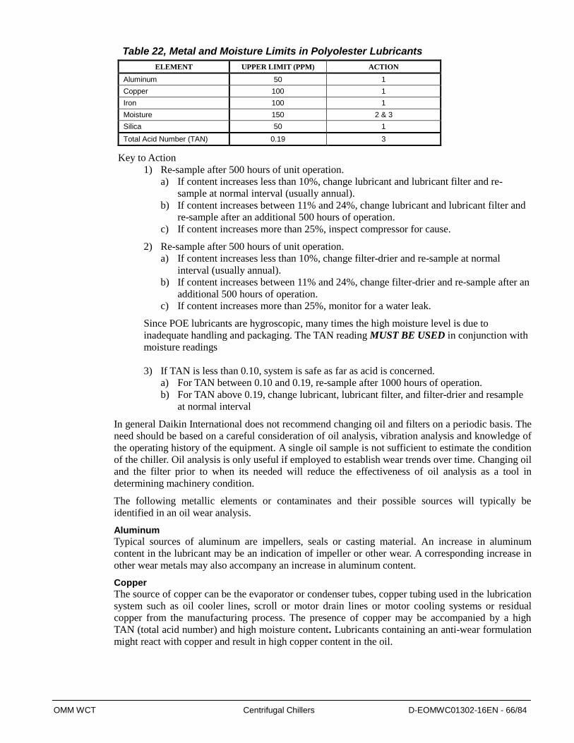
OMM WCT Centrifugal Chillers D-EOMWC01302-16EN - 66/84
Table 22, Metal and Moisture Limits in Polyolester Lubricants
ELEMENT UPPER LIMIT (PPM) ACTION
Aluminum 50 1
Copper 100 1
Iron 100 1
Moisture 150 2 & 3
Silica 50 1
Total Acid Number (TAN) 0.19 3
Key to Action
1) Re-sample after 500 hours of unit operation.
a) If content increases less than 10%, change lubricant and lubricant filter and re-
sample at normal interval (usually annual).
b) If content increases between 11% and 24%, change lubricant and lubricant filter and
re-sample after an additional 500 hours of operation.
c) If content increases more than 25%, inspect compressor for cause.
2) Re-sample after 500 hours of unit operation.
a) If content increases less than 10%, change filter-drier and re-sample at normal
interval (usually annual).
b) If content increases between 11% and 24%, change filter-drier and re-sample after an
additional 500 hours of operation.
c) If content increases more than 25%, monitor for a water leak.
Since POE lubricants are hygroscopic, many times the high moisture level is due to
inadequate handling and packaging. The TAN reading MUST BE USED in conjunction with
moisture readings
3) If TAN is less than 0.10, system is safe as far as acid is concerned.
a) For TAN between 0.10 and 0.19, re-sample after 1000 hours of operation.
b) For TAN above 0.19, change lubricant, lubricant filter, and filter-drier and resample
at normal interval
In general Daikin International does not recommend changing oil and filters on a periodic basis. The
need should be based on a careful consideration of oil analysis, vibration analysis and knowledge of
the operating history of the equipment. A single oil sample is not sufficient to estimate the condition
of the chiller. Oil analysis is only useful if employed to establish wear trends over time. Changing oil
and the filter prior to when its needed will reduce the effectiveness of oil analysis as a tool in
determining machinery condition.
The following metallic elements or contaminates and their possible sources will typically be
identified in an oil wear analysis.
Aluminum
Typical sources of aluminum are impellers, seals or casting material. An increase in aluminum
content in the lubricant may be an indication of impeller or other wear. A corresponding increase in
other wear metals may also accompany an increase in aluminum content.
Copper The source of copper can be the evaporator or condenser tubes, copper tubing used in the lubrication
system such as oil cooler lines, scroll or motor drain lines or motor cooling systems or residual
copper from the manufacturing process. The presence of copper may be accompanied by a high
TAN (total acid number) and high moisture content. Lubricants containing an anti-wear formulation
might react with copper and result in high copper content in the oil.
OMM WCT Centrifugal Chillers D-EOMWC01302-16EN - 67/84
Iron Iron in the oil may originate from compressor castings, oil pump components, shells, tube sheets,
tube supports, shaft material and rolling element bearings.
Zinc The source, if any may be from additives in lubricant.
Silicon
Silicon can originate from residual particles of silicon left from the manufacturing process, filter
drier material, or dirt.
Moisture Moisture in the form of dissolved water can be present in lubricating oil to varying degrees. Some
polyolester lubricants may contain up to 50 parts per million (ppm) of water from new unopened
containers. Other sources of water may be the refrigerant (new refrigerant may contain up to 10 ppm
water), leaking evaporator or condenser tubes, or moisture introduced by the addition of either
contaminated oil or refrigerant or improperly handled oil.
Liquid R-134a has the ability to retain up to 1400 ppm of water in solution at 100 F. With 225 ppm
of water dissolved in liquid R-134a, free water would not be released until the liquid temperature
reached -22 F. Liquid R-134a can hold approximately 470 ppm at 15F (an evaporator temperature
which could be encountered in ice applications). Since free water is what causes acid production,
moisture levels should not be of a concern until they approach the free water release point.
A better indicator of a condition which should be of concern is the TAN (Total Acid Number). A
TAN below 0.09 requires no immediate action. TANs above 0.09 require certain actions. In the
absence of a high TAN reading and a regular loss of oil (which may indicate a heat transfer surface
leak), a high moisture content in an oil analysis is probably due to handling or contamination of the
oil sample. It should be noted that air (and moisture) can penetrate plastic containers. Metal or glass
containers with gasket in the top will slow moisture entry.
In conclusion, a single element of an oil analysis should not be used as the basis to estimate the
overall internal condition of a Daikin chiller. The characteristics of the oil and refrigerant, and
knowledge of the interaction of wear materials in the chiller must be considered when interpreting a
wear metal analysis. Periodic oil analysis performed by a reputable laboratory and used in
conjunction with compressor vibration analysis and operating log review can be helpful tools in
estimating the internal condition of a Daikin chiller.
Daikin recommends that an oil analysis be performed annually. Professional judgment must be
exercised under unusual circumstances, for example, it might be desirable to sample the oil shortly
after a unit has been placed back into operation after it has been opened for service, as recommended
from previous sample results or after a failure. The presence of residual materials from a failure
should be taken into consideration in subsequent analysis. While the unit is in operation, the sample
should be taken from a stream of oil, not in a low spot or quiet area.
Changing Oil Filters
The oil filter in these compressors can be changed by simply isolating the filter cavities. Close the
oil discharge line service valve and the oil pressure regulator valve. Remove any refrigerant using
EPA approved methods, Remove the filter cover, remove the filter and replace with new element.
Reopen the valve in the pump discharge line and purge air from the lubricant filter cavity. Re-adjust
the oil pressure regulator valve for the right pressure differential setting @ 50psi (50Hz) / 36psi
(60Hz) after starting the oil pump manually and before restarting the chiller.
OMM WCT Centrifugal Chillers D-EOMWC01302-16EN - 68/84
Refrigerant Cycle
Maintenance of the refrigerant cycle includes maintaining a log of the operating conditions, and
checking that the unit has the proper lubricant and refrigerant charge.
At every inspection, all system pressures and temperatures should be recorded on a copy of the Log
Sheet on page 92.
The first stage suction temperature at the compressor should be taken at least once a month.
Subtracting the saturated temperature equivalent of the suction pressure from this will give the suction
superheat. Extreme changes in subcooling and/or superheat over a period of time may indicate losses
of refrigerant or possible deterioration or malfunction of the expansion valves. Proper superheat
setting is 0 to 2 degree F (1.0 degree C) at full load. Such a small temperature difference can be
difficult to measure accurately. Another method is to measure the compressor discharge superheat, the
difference between the actual second stage discharge temperature and the saturated condenser
temperature. The discharge superheat should be between 13 and 16 degrees F (7 to 9 degrees C) at full
load.
The MicroTech III interface panel can display all superheat and subcooling temperatures.
Electrical System
Maintenance of the electrical system involves the general requirement of keeping contacts clean and
connections tight and checking on specific items as follows:
1. The compressor current draw should be checked and compared to nameplate RLA value.
Normally, the actual current will be lower, since the nameplate rating represents full load
operation. Also check all pump and motor amperages, and compare with nameplate ratings.
2. Inspection must verify that the lubricant heaters are operative. The heaters are insert-cartridge
type and can be checked by ammeter reading. They should be energized whenever power is
available to the control circuit, when the lubricant temperature sensor calls for heat, and when
the compressor is inoperative. When the compressor runs, the heaters are de-energized. The
Digital Output screen and second View screen on the operator interface panel both indicate when
the heaters are energized.
3. At least once a quarter, all equipment protection controls except compressor overloads should be
made to operate and their operating points checked. A control can shift its operating point as it
ages, and this must be detected so the controls can be adjusted or replaced. Pump interlocks and
flow sensors should be checked to be sure they interrupt the control circuit when tripped.
4. The motor starter contactors should be maintained per starter manufacturer’s recommendations.
5. The compressor motor resistance to ground should be checked and logged annually. This log will
track insulation deterioration. A reading of 50 megohms or less indicates a possible insulation
defect or moisture and must be further checked.
6. The centrifugal compressor must rotate in the direction indicated by the arrow on the back of the
motor as viewed through the rotation sight glasses located in the rear motor cover.
CAUTION
Never meg a motor while in a vacuum. Severe motor damage can result. It is recommended to meg the motor after 24 hours of sitting idle at ambient temperature
CAUTION
Anytime external leads from motor are removed for servicing etc. the compressor must be jogged to check rotation after leads are reconnected at the start-up.
!
!
OMM WCT Centrifugal Chillers D-EOMWC01302-16EN - 69/84
Equipment Cleaning and Preserving A common cause of service calls and equipment malfunction is dirt. This can be prevented with
normal maintenance. The system components most subject to dirt are:
1. Permanent or cleanable filters in the air handling equipment must be cleaned in accordance with
the manufacturer’s instructions; throwaway filters should be replaced. The frequency of this
service will vary with each installation.
2. Remove and clean strainers in chilled water system and condenser water system at every
inspection.
Seasonal Servicing
Prior to shutdown periods and before starting up again, the following service procedures must be
completed.
Annual Shutdown ( Including Other Nonscheduled Extended Shutdown)
Where the chiller can be subject to freezing temperatures, the chiller must be drained of all water.
Water permitted to remain in the piping and vessels can rupture these parts if subjected to freezing
temperature. The condenser and evaporator are not self-draining and therefore, first drain the
condenser and evaporator heads. Then, remove the heads and blow dry air through the evaporator and
condenser tubes to force out all water out.
1. Take measures to prevent the shutoff valve in the water supply line from being accidentally
turned on.
2. If a cooling tower is used, and if the water pump will be exposed to freezing temperatures, be sure
to remove the pump drain plug and leave it out so any water that can accumulate will drain .
3. Open the compressor disconnect switch, and remove the fuses. If the transformer is used for
control voltage, the disconnect switch must remain on to provide power to the oil heater. Set the
manual UNIT ON/OFF switch in the unit control panel to the OFF position.
4. Check for corrosion and clean and paint rusted surfaces.
5. Clean and flush the water tower. Make sure tower blowdown or bleed-off is operating. Set up and
use a good maintenance program to prevent scaling of both tower and condenser. It should be
recognized that atmospheric air contains many contaminants that increase the need for proper
water treatment. The use of untreated water can result in corrosion, erosion, sliming, scaling or
algae formation. It is recommended that the service of a reliable water treatment company be
used. Daikin assumes no responsibility for the results of untreated or improperly treated water.
6. Drain water from the chiller and remove water heads at least once a year to inspect the condenser
and evaporator tubes and clean if required.
7. Test all chiller joints with an R-134a compatible electronic leak detector to be sure all joints are
tight. All leaks found should be repaired before a prolonged shutdown for a season.
Tube Fouling and Cleaning
Fouling is generally defined as the deposit of solid insulating material on a heat transfer surface, or
accumulation of unwanted material on solid surfaces. Over a period of time, due to poor water
quality caused by dirty strainers, unclean cooling tower conditions or environmental factors,
drawing water from lakes, rivers, and oceans, moisture or acidic conditions for tube corrosion may
exist. An accumulation of rust, debris, aquatic organisms or sludge inside the tubes may plug tubes
and will decrease heat transfer. The formation of thin mineral compounds or “scaling” such as
calcium carbonate, manganese compounds and silicates build up on the inner tube surfaces are other
type of deposits will cause tube fouling and poor heat transfer. The fouling results in a raised tube
temperature and condensing saturation temperature, with a resulting increase in the system power
requirement.
OMM WCT Centrifugal Chillers D-EOMWC01302-16EN - 70/84
Once formed, scale must be treated chemically with an acid solution treated water to remove these
types of hard deposits. Tubes can be cleaned with a nylon brush.
CAUTION
Do not clean with a steel bristle brush, which can cause tube damage. Always clean with a brush before acid cleaning of tubes. Cleaning tubes with water and brush together will improve results
CAUTION
Acid cleaning of tubes must only be performed by authorized and trained service personnel. For qualified assistance, contact your local Daikin Factory Service office.
Types of In-Tube Fouling :
1) Biological : The attachment of macro- and/or micro-organisms to the heat transfer surfaces.
slime deposits such as bacteria, fungi and algae.
2) Particulate : The accumulation of finely divided solids suspended in the fluid onto the heat
transfer surface. Formation of agglomerates (a jumbled mass or collection) at low velocities.
Airborne particles in cooling towers, rusting in pipes. Impurities such as chemicals, salts,
pollutants, dirt, rust are typically contained in the cooling water flowing inside a tube will
adhere to the tube inner surface. These impurities cause fouling in the heat transfer tubes after a
period of time and reduces the heat transfer across the tube wall.
Particulate fouling occur in evaporators.
3) Precipitation (Scale) : The precipitation of dissolved substances on the heat transfer surface.
When the dissolved substances have inverse rather than normal solubility – vs. – temperature
behavior, the precipitation occurs on superheated rather than subcooled surfaces and the process
is often referred to as scaling. Warmer the surface less soluble. Deposits on cold surfaces if bulk
solubilities are exceeded. In precipitation fouling, which may occur simultaneously with
particulate fouling, chemicals (dissolved solids) that are contained in the cooling water will
deposit on the inner surface of the tube if the concentration of the chemicals is higher than the
solubility limit at the water temperature. The precipitation of the chemicals onto the warmer
tube inner surface is caused by this reverse solubility of the chemicals typically found in cooling
water. The presence of precipitate fouling often results in an increase in the rate of particulate
fouling, because particles such as rust or dirt will more easily adhere to the inner tube surface if
chemicals have already adhered to the inner tube surface.
Fouling of the precipitation type is not as large of a problem in evaporators as in condenser because
the tube walls have a lower temperature than the water circulating inside. Because of the lower
temperature of the tube walls, the chemicals do not undergo inverse solubility as they do in the
condenser.
4) Corrosion : Corrosion of the heat transfer surface that produces products fouling the surface
and/or roughens the surface, promoting attachment of other foulants.Causes surface roughness,
adds corrosion products and promotes combinations of several fouling types.
5) Chemical Reaction : Deposits formed on the surface by a chemical reaction not involving the
surface material.
6) Freezing : The solidification of a liquid or some of its higher – melting point constituents on the
heat transfer surface. Freezing fouling is due to the solidification of vapor condensing from the
gas stream onto a below-freezing temperature heat transfer surface.
!
!
OMM WCT Centrifugal Chillers D-EOMWC01302-16EN - 71/84
Examples of harmful deposits (tubercles) are:
High amount of iron or metallic deposits due to corrosion occurring inside the iron/carbon steel
piping in the water circuit can be carried by the water to the tubes. These metallic deposits often
adhere or fuse themselves to the tube.
Molybdenum which is used as an iron corrosion inhibitor in water systems.
Sulfur which is known as an aggressive element in corrosion reactions, is a result of
environmental factors transferred to the water systems such as acid rain, auto exhaust etc.
The signs of tube fouling due to deposits can be observed as a decrease of evaporator capacity and
an increase of evaporator and/or condenser small temperature difference. In addition, lubricant loss
to the evaporator and refrigerant leak will also deteriorate the performance of evaporator. Therefore,
it is usually hard to isolate tube fouling as the only main cause for bad evaporator performance.
Water velocity, turbulence, or high temperature will cause erosion and combined with metal loss
created by corrosion might cause condenser tube foul.
Tube Leak Detection
Tubes can be ruptured or broken due to vibration, freezing, or corrosion etc.. Depends on the
shell and tube side pressures refrigerant might leak through the tubes to the cooling tower or
water might enter the shells.
Refrigerant leaks from the tubes can be detected at the heads using a refrigerant leak detector
whereas water leaks in the shells can be detected visually through the sight glasses or poor
chiller capacity.
Eddy current testing is recommended based on site conditions to determine any defective
tubes.
Annual Startup A dangerous condition can exist if power is applied to a faulty compressor motor starter that has
been burned out. This condition can exist without the knowledge of the person starting the
equipment.
This is a good time to check all the motor winding resistance to ground. Semi-annual checking and
recording of this resistance will provide a record of any deterioration of the winding insulation. All
new units have well over 100 megohms resistance between any motor terminal and ground.
Whenever great discrepancies in readings occur, or uniform readings of less than 50 megohms are
obtained, the motor cover must be removed for inspection of the winding prior to starting the unit.
Uniform readings of less than 5 megohms indicate motor failure is imminent and the motor should
be replaced or repaired. Repair before failure occurs can save a great deal of time and labor spent in
the cleanup of a system after a motor burnout.
1. The control circuit must be energized at all times, except during service. If the control circuit
has been off and lubricant is cool, energize lubricant heaters and allow 8 hours for heater to
remove refrigerant from the lubricant before starting.
2. Check and tighten all electrical connections.
3. Replace the drain plug in the cooling tower pump if it was removed at shutdown time the
previous season.
4. Install fuses in main disconnect switch (if removed).
5. Reconnect water lines and turn on supply water. Flush condenser and check for leaks.
6. Refer to the startup section of this manual before energizing the compressor circuit.
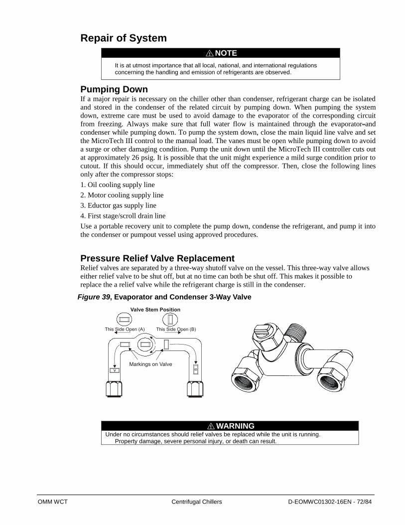
OMM WCT Centrifugal Chillers D-EOMWC01302-16EN - 72/84
Repair of System
NOTE
It is at utmost importance that all local, national, and international regulations concerning the handling and emission of refrigerants are observed.
Pumping Down If a major repair is necessary on the chiller other than condenser, refrigerant charge can be isolated
and stored in the condenser of the related circuit by pumping down. When pumping the system
down, extreme care must be used to avoid damage to the evaporator of the corresponding circuit
from freezing. Always make sure that full water flow is maintained through the evaporator and
condenser while pumping down. To pump the system down, close the main liquid line valve and set
the MicroTech III control to the manual load. The vanes must be open while pumping down to avoid
a surge or other damaging condition. Pump the unit down until the MicroTech III controller cuts out
at approximately 26 psig. It is possible that the unit might experience a mild surge condition prior to
cutout. If this should occur, immediately shut off the compressor. Then, close the following lines
only after the compressor stops:
1. Oil cooling supply line
2. Motor cooling supply line
3. Eductor gas supply line
4. First stage/scroll drain line
Use a portable recovery unit to complete the pump down, condense the refrigerant, and pump it into
the condenser or pumpout vessel using approved procedures.
Pressure Relief Valve Replacement Relief valves are separated by a three-way shutoff valve on the vessel. This three-way valve allows
either relief valve to be shut off, but at no time can both be shut off. This makes it possible to
replace the a relief valve while the refrigerant charge is still in the condenser.
Figure 39, Evaporator and Condenser 3-Way Valve
WARNING
Under no circumstances should relief valves be replaced while the unit is running. Property damage, severe personal injury, or death can result.
!
!

OMM WCT Centrifugal Chillers D-EOMWC01302-16EN - 73/84
Leak Testing After a service repair, the unit must be checked for leaks prior to recharging the complete system.
This can be done by charging enough refrigerant R-134a into the system to build the pressure up to
approximately 10 psig (69 kPa) and adding sufficient dry nitrogen to bring the pressure up to a
maximum of 125 psig (860 kPa). Leak test with an R-134a compatible electronic leak detector to be
sure all joints are tight. Halide leak detectors do not function with R-134a.
Leak testing should be focused on the areas worked on. Leaks around tubing or fitting connections
can often be stopped by simply tightening them. However, for any leaks that are found in welded or
brazed joints, or if it is necessary to replace a gasket, relieve the test pressure in the system before
proceeding. Brazing is required for copper joints.
After it has been determined that there are no refrigerant leaks, the system must be evacuated as
described in the following section starting from step 3 in the following Evacuation section.
WARNING
Do not use oxygen or a mixture of refrigerants and air to build up pressure as an explosion can occur causing serious personal injury.
Evacuation of the System If there is a need for major service work on the chiller or on the condenser for any of the circuits
and the whole charge must be evacuated then proceed as follows:
1) Connect the service valve at the bottom of the condenser to the refrigerant cylinder and start
taking charge out while running the unit at full load with high condenser water inlet temperature
until the unit shuts down on low evaporator pressure.
2) Continue taking liquid charge out after shutdown while circulating warm condenser water in the
unit to keep the condenser pressure higher than the cylinder pressure.
3) Once the pressures between the cylinder and unit equalizes, connect a recovery unit with a
capacity that will reduce the vacuum to the acceptable EPA standards.
4) An electronic or other type of micron gauge, must be connected at the farthest point from the
vacuum pump. For readings below 1000 microns, an electronic or other micron gauge must be used.
5) To improve evacuation circulate warm water not to exceed 122 F ( 50
C ) through the condenser
and evaporator tubes to thoroughly dehydrate the shells. A portable water heater can be employed as
an alternative source for hot water. A suggested method is to connect a hose between the source of
hot water under pressure and the evaporator head drain connection, out the evaporator vent
connection, into the condenser head drain and out the condenser vent back to the inlet of the water
heater.
6) The triple evacuation method may be necessary due to severe contamination of the refrigerant.
7) The system is first evacuated to approximately 500 microns. Dry nitrogen is then added to the
system to bring the pressure up to zero pounds.
8) Then the system is once again evacuated to approximately 500 microns.
9) After evacuation is completed to 500 microns, a vacuum hold test should be conducted.
10) Close the condenser service valve to the vacuum pump and hold the vacuum in the system for 4
hours. The slightest rise in pressure is an indication of either a leak to the atmosphere or the
moisture in the chiller or both. If, after 4 hours the micron gauge has not risen above 1000 microns,
the system may be considered tight.
11) If the vacuum hold test fails then do another leak test.
!

OMM WCT Centrifugal Chillers D-EOMWC01302-16EN - 74/84
12) If the vacuum hold test fails use Table 32 to determine if the failure is due to a leak or
water/moisture in the unit. If the vacuum level rises above water saturation point then do another
leak test. If it stops at water saturation temperature, continue evacuation until dry or source
determined.
Table 23, Pressure Chart
Notes:
1. psia ( pounds per square inch absolute ): sum of gage and atmospheric pressures
2. psig ( pounds per square inch gage ): pressure over atmospheric pressure
3. vacuum: pressure below atmospheric i.e. negative gage pressure (always stated as positive numbers)
4. in. Hg: inches of mercury, mm Hg: millimeters of mercury
Charging the System WCT water chillers are leak tested at the factory and the correct charge of refrigerant is indicated on
the nameplate.
In the event the refrigerant charge was lost due to leak(s) or the unit exhibits a lack of performance
due to insufficient amount of charge, the system should be charged or trimmed.
In order to ease the evacuation, charging and trimming, service connection valves are provided at the
top and bottom of condenser and evaporator and at the bottom of economizer as well as sight glasses
on the evaporator, economizer, and condenser.
If there are any leaks found then first repair the leaks.
If the system is evacuated due to service and is still under a vacuum then in order to put charge back
into the system follow these steps which are applicable for both circuits :
1. Make up a suitable charging connection from new copper tubing or yellow jacket/flexible hose
to fit between the chiller charging valve and the fitting on the refrigerant charging cylinder. This
connection should be as short as possible but long enough to permit sufficient flexibility for
charging cylinders.
GAGE PRESSURE
ABSOLUTE PRESSURE WATER TEMPERATURE AT
SATURATION oF
VACUUM
in. Hg psia in. Hg mm Hg Microns
0 14.696
( Std. at Sea Level ) 29.921 760 760,000 212 (Water Boiling Temperature)
10.24 9.668 19.68 500 500,000 192
22.05 3.867 7.87 200 200,000 152
25.98 1.934 3.94 100 100,000 125
27.95 0.967 1.97 50 50,000 101
28.94 0.483 0.98 25 25,000 78
29.53 0.193 0.39 10 10,000 52
29.72 0.097 0.20 5 5,000 34
29.74 0.089 0.18 4.58 4,580 32 (Water Freezing Temperature)
29.842 0.039 0.08 2 2,000 15
29.882 0.019 0.04 1 1,000 1
29.901 0.010 0.02 0.50 500 -11
29.909 0.006 0.01 0.30 300 -20
29.917 0.002 0.004 0.10 100 -38
29.919 0.001 0.002 0.05 50 -50
29.9206 0.0002 0.0004 0.01 10 -73
29.921 0 0 0.00 0

OMM WCT Centrifugal Chillers D-EOMWC01302-16EN - 75/84
2. Stand the refrigerant cylinder with the connection up. In order to avoid possibility of freezing the
liquid within the evaporator tubes when charging an evacuated system, only refrigerant vapor
from the top of the refrigerant cylinder must be admitted first.
3. Just before connecting the charging line to the service valve on top of the evaporator, open the
valve on the cylinder and purge any air in the charging line.
4. After purging the charging connection and connecting the line to the evaporator, keep the
evaporator service valve closed while the cylinder valve is open. The charging line should be
filled with refrigerant and with very little or no air at this point.
NOTE
While charging, every precaution must be taken to prevent moisture laden air from entering the system.
5. Turn on both the cooling tower water pump and chilled water pump and allow water to circulate
through the chiller. In order to lower the chiller system pressure, low water temperature is
recommended to accelerate the charging. Chiller system pressure as well as refrigerant cylinder
pressure should be monitored during charging process. Make sure the cylinder pressure is always
higher than the chiller system pressure in order to maintain refrigerant flow by pressure
differential.
6. If there is oil in the oil sump, then energize the oil heater before charging with any refrigerant.
This will keep the oil hot and prevent any refrigerant concentration in the oil by boiling of the
refrigerant from the oil.
7. Then open the service valve on top of the evaporator to the mid-position and break the vacuum
with refrigerant gas to a saturated pressure above the point corresponding to the freezing point of
the liquid to avoid the possibility of freezing liquid within the evaporator tubes. If the liquid is
water, then the system pressure corresponding to the freezing point would be 28 psig ( 0.19
MPaG ) for R-134a ( at sea level ). Therefore, keep charging with refrigerant vapor until the
chiller pressure is well above 28 psig.
8. After the chiller pressure is above 28 psig by gas charging, the rest of the charge could be put
into the system by refrigerant liquid form and without water circulation even though running
water pumps until the end of charging process is strongly recommended.
9. Reconnect the refrigerant cylinder and charging line to the service valve on the bottom of the
evaporator. Again purge the connecting line, stand the cylinder with the connection up, and place
the service valve in the open position.
10. At some point both the chiller and cylinder pressures might equalize with each other during the
charging process and in return that might slow or stop the process. However, there a few ways to
prevent situations like this (see #11 – 14 below).
11. Circulate cold water through the evaporator and condenser tubes to keep the chiller system
pressure lower.
12. If there is a crane in the facility, invert the charging cylinder and elevate the cylinder above the
evaporator. With the cylinder in this position, valves open, water pumps operating, liquid
refrigerant will flow into the evaporator by gravitational force.
13. If there is no crane capability in the facility, heat lamps are recommended to heat the cylinder to
raise the pressure. A recovery unit can be used to create a pressure difference.
14. If there are no crane or heat lamps available, then start the chiller and run at part load and low
condenser water temperature. Low evaporator pressure will improve and accelerate the rest of
the charging rapidly.
If charge needs to be added to improve performance, repeat Step 8 above while the chiller is running
at full load capacity and check the refrigerant charge level through sight glasses. The level on the
!
OMM WCT Centrifugal Chillers D-EOMWC01302-16EN - 76/84
condenser sight glass should be about an inch above the subcooler trough cover plate without any
condenser tubes at the bottom immersed in the liquid, and about an inch above the evaporator tubes
all wetted but not totally immersed. Capacity of the chiller and discharge superheat should also be
monitored through the main control console in order to manage the process.
If charge needs to be taken out during trimming for optimum performance then repeat Step 8 with
connection to the bottom of the condenser during running at high load/high head condition or at full
load with high condenser water inlet temperature. The refrigerant charge level and capacity should be
monitored as explained above in order to regulate trimming.
NOTE
Record the charge amount and level of charge in the evaporator and condenser sight glasses if refrigerant amount has been changed.
!
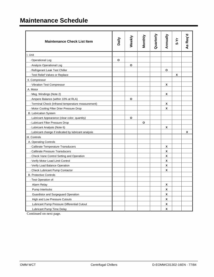
OMM WCT Centrifugal Chillers D-EOMWC01302-16EN - 77/84
Maintenance Schedule
Maintenance Check List Item
Daily
Weekly
Mo
nth
ly
Qu
art
erl
y
An
nu
ally
5-Y
r
As R
eq
’d
I. Unit
· Operational Log O
· Analyze Operational Log O
· Refrigerant Leak Test Chiller O
· Test Relief Valves or Replace X
II. Compressor
· Vibration Test Compressor X
A. Motor
· Meg. Windings (Note 2) X
· Ampere Balance (within 10% at RLA) O
· Terminal Check (Infrared temperature measurement) X
· Motor Cooling Filter Drier Pressure Drop X
B. Lubrication System
· Lubricant Appearance (clear color, quantity) O
- Lubricant Filter Pressure Drop O
· Lubricant Analysis (Note 6) X
· Lubricant change if indicated by lubricant analysis X
III. Controls
A. Operating Controls
· Calibrate Temperature Transducers X
· Calibrate Pressure Transducers X
· Check Vane Control Setting and Operation X
· Verify Motor Load Limit Control X
· Verify Load Balance Operation X
· Check Lubricant Pump Contactor X
B. Protective Controls
· Test Operation of:
Alarm Relay X
Pump Interlocks X
Guardistor and Surgeguard Operation X
High and Low Pressure Cutouts X
Lubricant Pump Pressure Differential Cutout X
Lubricant Pump Time Delay X
Continued on next page.
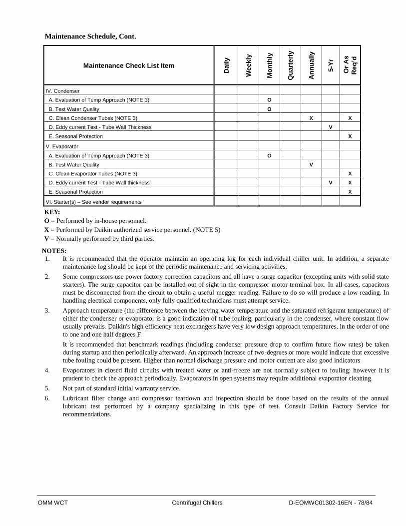
OMM WCT Centrifugal Chillers D-EOMWC01302-16EN - 78/84
Maintenance Schedule, Cont.
Maintenance Check List Item
Daily
Weekly
Mo
nth
ly
Qu
art
erl
y
An
nu
ally
5-Y
r
Or
As
Req
’d
IV. Condenser
A. Evaluation of Temp Approach (NOTE 3) O
B. Test Water Quality O
C. Clean Condenser Tubes (NOTE 3) X X
D. Eddy current Test - Tube Wall Thickness V
E. Seasonal Protection X
V. Evaporator
A. Evaluation of Temp Approach (NOTE 3) O
B. Test Water Quality V
C. Clean Evaporator Tubes (NOTE 3) X
D. Eddy current Test - Tube Wall thickness V X
E. Seasonal Protection X
VI. Starter(s) – See vendor requirements
KEY:
O = Performed by in-house personnel.
X = Performed by Daikin authorized service personnel. (NOTE 5)
V = Normally performed by third parties.
NOTES:
1. It is recommended that the operator maintain an operating log for each individual chiller unit. In addition, a separate
maintenance log should be kept of the periodic maintenance and servicing activities.
2. Some compressors use power factory correction capacitors and all have a surge capacitor (excepting units with solid state
starters). The surge capacitor can be installed out of sight in the compressor motor terminal box. In all cases, capacitors
must be disconnected from the circuit to obtain a useful megger reading. Failure to do so will produce a low reading. In
handling electrical components, only fully qualified technicians must attempt service.
3. Approach temperature (the difference between the leaving water temperature and the saturated refrigerant temperature) of
either the condenser or evaporator is a good indication of tube fouling, particularly in the condenser, where constant flow
usually prevails. Daikin's high efficiency heat exchangers have very low design approach temperatures, in the order of one
to one and one half degrees F.
It is recommended that benchmark readings (including condenser pressure drop to confirm future flow rates) be taken
during startup and then periodically afterward. An approach increase of two-degrees or more would indicate that excessive
tube fouling could be present. Higher than normal discharge pressure and motor current are also good indicators
4. Evaporators in closed fluid circuits with treated water or anti-freeze are not normally subject to fouling; however it is
prudent to check the approach periodically. Evaporators in open systems may require additional evaporator cleaning.
5. Not part of standard initial warranty service.
6. Lubricant filter change and compressor teardown and inspection should be done based on the results of the annual
lubricant test performed by a company specializing in this type of test. Consult Daikin Factory Service for
recommendations.

OMM WCT Centrifugal Chillers D-EOMWC01302-16EN - 79/84
EVAPORATOR :
CONDENSER
SYMPTOM RESULTS Possible Cause Remedy
Extreme Low
Suction Pressure
High Evaporator Approach Temperature with
High Discharge Temperature
Low Charge Check for leaks and add charge
EXV problem Remove obstruction
High Evaporator Approach Temperature with
Normal Discharge Temp
Dirty or restricted
evaporator tubes
Clean Evaporator Tubes and/or
Check water conditioning
Low Evaporator water leaving
Temperature with w/ Low Motor
Current
Insufficient Load for system
capacity
Check IGV motor operation and set point
of Evaporator water leaving temperature
cutout
Check Cutout setting and increase it if
necessary so Evaporator water leaving
temperature will not be so low and the unit will shut
down NOT causing low suction
pressure anymore
IGV might not be Full Open but not give enough load
due to linkage slippage etc.
High Evaporator
pressure
Low Evaporator water leaving
Temperature
IGV failed to open Check the IGV motor positioning circuit
System Overload Be sure the vanes are wide open without
overloading the motor until the load
decreases
Low discharge
superheat
Overall reduced performance due
to refrigerant accumulation in
Evaporator
Economizer float
valves are stuck
open
Adjust EXV until system stabilizes
SYMPTOM RESULTS Possible Cause Remedy
Extreme High
Discharge Pressure
Condenser Approach temperature is
higher than normal
Air in Condenser Take refrigerant charge out and put the unit
on a vacuum pump and then recharge
High Condenser water range with
normal Evaporator temperature
Insufficient
Condenser water
flow rate
Increase Condenser water flow rate
Overall performance loss Condenser Tubes
are dirty/scaled
Clean Condenser tubes and/or check water
conditioning
High Condenser
water entering
temperature
Reduce Condenser water entering
Temperature (check cooling tower and
water circulation)

OMM WCT Centrifugal Chillers D-EOMWC01302-16EN - 80/84
OIL SIDE
SYMPTOM RESULTS Possible Cause Remedy
Small Evaporator
water pressure
difference between
water entering and leaving
Capacity Loss and high
Evaporator approach
temperature
Evaporator pass baffle
gasket damage
Stop unit operation, drain water, remove
water box and replace gasket
Fluctuating unsteady
water flow
Pass baffle gasket damage Air in water boxes Vent any air from the chiller water boxes
prior to starting the water pumps
SYMPTOM RESULTS Possible Cause Remedy
No oil pressure when
system start button pushed
Low oil press displayed on
control center and compressor
will not start
Oil pump running in
wrong direction
Check rotation of oil pump - electrical
connections
Oil pump not running Troubleshoot electrical problem with
oil pump
Oil pressure regulator
valve is not adjusted
Adjust oil pressure regulator valve to
maintain proper oil pressure differential
before the start-up
Unusually high oil
pressure develops when
oil pump runs
High oil pressure is displayed
on control center when the oil
pump is running
Defective oil pressure
transducer or oil
pressure regulator
valve is not adjusted
Adjust oil pressure regulator valve to
maintain proper oil pressure differential
and/or check oil pressure transducer
Oil pump vibrates or is
noisy
Oil pump vibrates or is
extremely noisy with some oil
pressure
Oil not reaching pump
suction inlet in sufficient
quantity
Check Oil Level
Worn or Failed Pump Repair/Replace Oil Pump
Reduced Oil Pump
Capacity
Oil pump pumping capacity Excessive end
clearance pump
Inspect and replace worn parts
Other worn pump parts
Partially blocked oil
supply inlet
Check oil inlet for blockage
Oil Pressure Gradually
Decreases
Oil filter is dirty Change oil filter
Oil loss during operation
Oil level is decreasing in
oil sump
Filter-drier in oil return
system dirty
Replace old filter-drier with a new one.
Orifice of oil return jet
clogged
Remove orifice, inspect for dirt, remove dirt
using solvent and replacement
No oil pressure display No oil pressure registers on
the control panel when oil
pump runs
Faulty oil pressure
transducer
Replace oil pressure transducer
Faulty
wiring/connectors
Inspect oil transducer wiring connections
to the panel
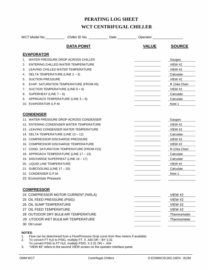
OMM WCT Centrifugal Chillers D-EOMWC01302-16EN - 81/84
PERATING LOG SHEET
WCT CENTRIFUGAL CHILLER
WCT Model No.__________ Chiller ID No. __________ Date __________ Operator ________________
DATA POINT VALUE SOURCE
EVAPORATOR
1. WATER PRESSURE DROP ACROSS CHILLER Gauges
2. ENTERING CHILLED WATER TEMPERATURE VIEW #2
3. LEAVING CHILLED WATER TEMPERATURE VIEW #2
4. DELTA TEMPERATURE (LINE 2 – 3) Calculate
5. SUCTION PRESSURE VIEW #2
6. EVAP. SATURATION TEMPERATURE (FROM #5) R 134a Chart
7. SUCTION TEMPERATURE (LINE 8 + 6) VIEW #2
8. SUPERHEAT (LINE 7 – 6) Calculate
9. APPROACH TEMPERATURE (LINE 3 – 6) Calculate
10. EVAPORATOR G.P.M. Note 1
CONDENSER
11. WATER PRESSURE DROP ACROSS CONDENSER Gauges
12. ENTERING CONDENSER WATER TEMPERATURE VIEW #2
13. LEAVING CONDENSER WATER TEMPERATURE VIEW #2
14. DELTA TEMPERATURE (LINE 13 – 12) Calculate
15. COMPRESSOR DISCHARGE PRESSURE VIEW #2
16. COMPRESSOR DISCHARGE TEMPERATURE VIEW #2
17. COND. SATURATION TEMPERATURE (FROM #15) R-134a Chart
18. APPROACH TEMPERATURE (LINE 17 – 13) Calculate
19. DISCHARGE SUPERHEAT (LINE 16 – 17) Calculate
20. LIQUID LINE TEMPERATURE VIEW #2
21. SUBCOOLING (LINE 17 – 20) Calculate
22. CONDENSER G.P.M. Note 1
23 Economizer Pressure
COMPRESSOR
24 COMPRESSOR MOTOR CURRENT (%RLA) VIEW #2
25 OIL FEED PRESSURE (PSIG) VIEW #2
26 OIL SUMP TEMPERATURE VIEW #2
27 OIL FEED TEMPERATURE VIEW #2
28 OUTDOOR DRY BULB AIR TEMPERATURE Thermometer
29 UTDOOR WET BULB AIR TEMPERATURE Thermometer
30 Oil Level
NOTES:
1. Flow can be determined from a Flow/Pressure Drop curve from flow meters if available. 2. To convert FT H20 to PSIG, multiply FT. X .434 OR ÷ BY 2.31
To convert PSIG to FT H20, multiply PSIG. X 2.31 OR ÷ .434 3. “VIEW #2” refers to the second VIEW screen on the operator interface panel.

OMM WCT Centrifugal Chillers D-EOMWC01302-16EN - 82/84
Service Programs
It is important that an air conditioning system receive adequate maintenance if the full equipment life
and full system benefits are to be realized.
Maintenance should be an ongoing program from the time the system is initially started. A full
inspection should be made after 3 to 4 weeks of normal operation on a new installation, and on a
regular basis thereafter.
Daikin offers a variety of maintenance services through the local Daikin service office, its worldwide
service organization, and can tailor these services to suit the needs of the building owner. Most popular
among these services is the Daikin Comprehensive Maintenance Contract.
For further information concerning the many services available, contact your local Daikin service
office.
Operator Schools
Daikin conducts training for centrifugal operators at its factory Training Center in Staunton, Virginia,
USA several times a year. These sessions are structured to provide basic classroom instruction and
include hands-on operating and troubleshooting exercises. For further information, contact your Daikin
representative.
Training courses for Centrifugal Maintenance and Operation are held through the year at the Daikin
Training Center. The school duration is three and one-half days and includes instruction on basic
refrigeration, MicroTech controllers, enhancing chiller efficiency and reliability, MicroTech
troubleshooting, system components, and other related subjects. Further information can be found on
www.Daikineurope.com or call Daikin and ask for the Training Department.
Warranty Statement
Limited Warranty
Consult your local Daikin Representative for warranty details. Refer to Form 933-43285Y. To find
your local Daikin Representative, go to www. Daikineurope.com.
The following are trademarks or registered trademarks of their respective companies: Loctite
from Henkel Company; 3M, Scotchfil and Scotchkote from the 3M Company; Victaulic from Victaulic
Company; Megger from Megger Group Limited; Distinction Series, MicroTech III and Protocol
Selectability from Daikin.


The present publication is drawn up by of information only and does not constitute an offer binding upon Daikin Applied Europe S.p.A.. Daikin
Applied Europe S.p.A. has compiled the content of this publication to the best of its knowledge. No express or implied warranty is given for the
completeness, accuracy, reliability or fitness for particular purpose of its content, and the products and services presented therein. Specification
are subject to change without prior notice. Refer to the data communicated at the time of the order. Daikin Applied Europe S.p.A. explicitly
rejects any liability for any direct or indirect damage, in the broadest sense, arising from or related to the use and/or interpretation of this
publication. All content is copyrighted by Daikin Applied Europe S.p.A..
DAIKIN APPLIED EUROPE S.p.A. Via Piani di Santa Maria, 72 - 00072 Ariccia (Roma) - Italia
Tel: (+39) 06 93 73 11 - Fax: (+39) 06 93 74 014
http://www.daikinapplied.eu