Council Chambers in Kaysville City Hall at 23 East Center ...
105
MEETING NOTICE AND AGENDA Notice is hereby given that the Kaysville City Council will hold a regular council meeting on Thursday, October 21, 2021, starting at 7:00 P.M. in the Council Chambers in Kaysville City Hall at 23 East Center Street, Kaysville, UT. The meeting will be streamed on YouTube, and the link to the meeting will be posted on www.KaysvilleLive.com. For those wishing to direct comments to the City Council can do so in-person, or email comments to [email protected]. Emailed comments will NOT be read out-loud at the meeting. Members wishing to speak during an Action Items or during Call to the Public must sign-up in person before the meeting to speak. CITY COUNCIL Q&A – 6:30 P.M. The City Council will be available to answer questions or discuss any matters the public may have. CITY COUNCIL MEETING – 7:00 P.M. The agenda shall be as follows: 1. OPENING a. Provided by Council Member Michelle Barber. 2. PRESENTATIONS AND AWARDS a. Kaysville University Graduation. b. Swearing-in of Youth City Council. c. Presentation by Davis County Elections. 3. DECLARATION OF ANY CONFLICTS OF INTEREST 4. CONSENT ITEMS a. Approval of Minutes of September 16, 2021. 5. ACTION ITEMS a. A Resolution enacting several fire related fees of the Consolidated Fee Schedule. b. An Ordinance amending Section 15-1-1 regarding definitions and enacting Section 15-9 entitled “Restrictions on Retail Pet Sales”. c. An Ordinance amending various chapters of Title 18, Building Regulations, and Title 19, Subdivisions, updating various storm water requirements. d. An Ordinance enacting development guidelines and design standards. 6. CALL TO THE PUBLIC (3 MINUTE LIMIT, MUST SIGN UP IN PERSON) 7. COUNCIL MEMBER REPORTS 8. CITY MANAGER REPORT 9. ADJOURNMENT Kaysville City is dedicated to a policy of non-discrimination in admission to, access to, or operations of its programs, services, or activities. If you need special assistance due to a disability, please contact the Kaysville City Offices at (801) 546-1235 at least 24 hours in advance of the meeting to be held. I hereby certify that I posted a copy of the foregoing Notice and Agenda and emailed copies to media representatives on October 15, 2021. __________________ Annemarie Plaizier City Recorder
Transcript of Council Chambers in Kaysville City Hall at 23 East Center ...

MEETING NOTICE AND AGENDA
Notice is hereby given that the Kaysville City Council will hold a regular council meeting on Thursday, October 21, 2021, starting at 7:00 P.M. in the Council Chambers in Kaysville City Hall at 23 East Center Street, Kaysville, UT. The meeting will be streamed on YouTube, and the link to the meeting will be posted on www.KaysvilleLive.com. For those wishing to direct comments to the City Council can do so in-person, or email comments to [email protected]. Emailed comments will NOT be read out-loud at the meeting. Members wishing to speak during an Action Items or during Call to the Public must sign-up in person before the meeting to speak. CITY COUNCIL Q&A – 6:30 P.M. The City Council will be available to answer questions or discuss any matters the public may have. CITY COUNCIL MEETING – 7:00 P.M. The agenda shall be as follows:
1. OPENING
a. Provided by Council Member Michelle Barber.
2. PRESENTATIONS AND AWARDS a. Kaysville University Graduation. b. Swearing-in of Youth City Council. c. Presentation by Davis County Elections.
3. DECLARATION OF ANY CONFLICTS OF INTEREST
4. CONSENT ITEMS a. Approval of Minutes of September 16, 2021.
5. ACTION ITEMS
a. A Resolution enacting several fire related fees of the Consolidated Fee Schedule. b. An Ordinance amending Section 15-1-1 regarding definitions and enacting Section 15-9 entitled “Restrictions on
Retail Pet Sales”. c. An Ordinance amending various chapters of Title 18, Building Regulations, and Title 19, Subdivisions, updating
various storm water requirements. d. An Ordinance enacting development guidelines and design standards.
6. CALL TO THE PUBLIC (3 MINUTE LIMIT, MUST SIGN UP IN PERSON)
7. COUNCIL MEMBER REPORTS
8. CITY MANAGER REPORT
9. ADJOURNMENT Kaysville City is dedicated to a policy of non-discrimination in admission to, access to, or operations of its programs, services, or activities. If you need special assistance due to a disability, please contact the Kaysville City Offices at (801) 546-1235 at least 24 hours in advance of the meeting to be held. I hereby certify that I posted a copy of the foregoing Notice and Agenda and emailed copies to media representatives on October 15, 2021. __________________ Annemarie Plaizier City Recorder

DRAFT
1
KAYSVILLE CITY COUNCIL September 16, 2021
Minutes of a regular Kaysville City Council meeting held on September 16, 2021 at 7:00 p.m. in the Council Chambers in Kaysville City Hall at 23 East Center Street, Kaysville, UT.
Council Members present: Mayor Katie Witt, Council Member Michelle Barber, Council Member Mike Blackham, Council Member Andre Lortz, and Council Member Tamara Tran
Excused: Council Member John Swan Adams
Others Present: City Manager Shayne Scott, City Attorney Nic Mills, City Recorder Annemarie Plaizier, Community Development Director Lyle Gibson, Information Systems Manager Ryan Judd, Assistant Police Chief Seth Ellington, Sam Taylor, Mark Vlasil, Howard Taylor, Chris Taylor, Abby Hunt, Jay Welk
OPENING
Council Member Tran opened the meeting with a prayer and led the audience in the pledge ofallegiance.
PRESENTATIONS AND AWARDS
PROCLAMATION DECLARING OCTOBER 3-9, 2021 AS PUBLIC POWER WEEK
Mayor Witt read a proclamation declaring October 3-9, 2021 as Public Power Week to recognize the people behind public power at Kaysville Power and Light for their contributions to thecommunity. Mayor Witt encouraged the residents to join in thanking our public power employeeswho help to bring low-cost, safe, reliable electricity to our community and businesses.
KAYSVILLE CITY GENERAL PLAN PRESENTATION
Sam Taylor, with Landmark Design, explained that their company has been working with the cityas a planning consultant over a year now and have been helping to put together an update on thecity’s General Plan. Mr. Taylor explained they started by looking at existing conditions in thePlan, and then conducted a needs assessment. They held public scoping meetings and workshopsto reach out to the public to see what they would like to see for the city. They used the data and feedback collected to create a draft plan and have since been working with the Planning Commission and advisory committee to refine the Plan. Most residents’ responses indicated thatthey would prefer to see future development concentrated in downtown Kaysville, along 200 North, Main Street, Flint Street, and Deseret Drive. When asked what type of development theywould like to see, there was a lot of interest in mixed-use low-rise, retail, and restaurant type ofuses. People seemed to be very interested in the city having more of a variety than what we havehad. Mr. Taylor explained that they took this feedback and created a couple of concept land useplans focusing on these concentrated areas along main arterial streets. The concept plans also introduced mixed-uses. Residents want to have historic Main Street remain untouched from
DRAFT
2
development. They also want any remaining undeveloped land in west Kaysville to remain as open space or be single-family neighborhoods. With the West Davis Corridor connecting to 200 North it will potentially bring some opportunities for small commercial development in this area. Their transportation consultant has been reviewing the city’s transportation grid and the principal needs of the city, particularly getting better access across the freeway. They also looked at the city’s parks system and distribution to see which areas have better access than others. In looking at all these different areas, they were able to create a placemaking plan which helps the city to see which areas might be best to focus their efforts on. This is essentially how the draft General Plan was created and it helps to give a vision of the future of Kaysville. The Plan indicates that the city is working to preserve existing neighborhoods while accommodating a full range of housing opportunities to meet the needs of residents. The city wants to ensure future growth and development are aligned with the city’s transportation and infrastructure capacities. The draft plan also builds upon the already adopted Active Transportation Plan. The next step in consideration of adopting the General Plan will include an online comment period. The plan will be posted where the public can review and make comments regarding the proposed General Plan updates. They will also be holding a Public Open House on October 6th where the public can come to review, comment, and ask questions about the General Plan. The Advisory Committee will then review the draft plan and public comments provided, and then make amendments as needed. From there the Plan will go before the Planning Commission for review and to hold a Public Hearing. They hope to have the draft before the City Council to review by the beginning of November, and officially adopted before the end of the year. Council Member Lortz commented that he would like to see redevelopment of Main Street considered. If those businesses would like to redevelop, they should be given the opportunity to do so. Especially if it would create more parking and a better traffic flow. Council Member Lortz added that he would also like to see a commercial district on the west side of the city. Sam Taylor responded that the biggest challenge they faced when looking at the redevelopment of Main Street is the commercial properties abuts the historic district. The more development allowed here, the more infringement would occur into the residential area. Since parking was the biggest concern, they decided that it would be best to focus their efforts in improving the street corridor itself. DECLARATION OF ANY CONFLICTS OF INTEREST No conflicts were disclosed. CONSENT ITEMS Council Member Blackham made a motion to accept the following consent items:
a. Approval of Minutes of August 19, 2021. b. Kaysville Wilderness Park Boundary Line Agreement.
The motion was seconded by Council Member Tran. The vote on the motion was as follows: Council Member Barber, yea Council Member Blackham, yea
DRAFT
3
Council Member Tran, yea Council Member Lortz, yea The motion passed unanimously. C. AWARD OF BID AND A RESOLUTION AUTHORIZING AN AGREEMENT WITH CONNEXT FOR THE 2021 FIBER RING FACILITY CONNECTION PROJECT Council Member Blackham asked if this resolution included the stipulation that the project could not exceed the amount outlined in the bid. Nic Mills responded that the stipulation has been included as Item #4 within the resolution that states, “The final Agreement shall not exceed the bid price without further action of this council.” Council Member Lortz commented that this vendor is deploying a private fiber opportunity and because of the unique timing, it will allow the city to have improvements constructed to the city’s fiber ring at a much-reduced cost. This agreement is not to connect fiber to homes through the city but only to extend the city’s existing fiber ring. However, the vendor has indicated that they are interested in extending fiber to homes privately. Council Member Lortz made a motion to approve the award of bid and Resolution authorizing an Agreement with Connext for the 2021 Fiber Ring Facility Connection Project, seconded by Council Member Barber. The vote on the motion was as follows: Council Member Blackham, yea Council Member Tran, yea Council Member Lortz, yea Council Member Barber, yea The motion passed unanimously. ACTION ITEMS A RESOLUTION AUTHORIZING NEGOTIATIONS WITH CENTRAL DAVIS SEWER DISTRICT TO ACQUIRE NECESSARY RIGHT-OF-WAY AND FINALIZE ANY NEGOTIATIONS WITHIN SET PARAMETERS Shayne Scott explained that the city would like to obtain real property from Central Davis Sewer District to improve road connectivity relating to the West Davis Corridor. Central Davis Sewer District has expressed interest in exchanging this property for certain improvements that would benefit the services they provide. This resolution authorizes the City Manager to conduct negotiations to acquire the necessary real property. The resolution also sets forth parameters for the Manager to negotiate within, and then to execute documents to finalize the exchange.

DRAFT
4
Council Member Tran made a motion to approve a Resolution authorizing negotiations with Central Davis Sewer District to acquire necessary right-of-way and finalize any negotiations within set parameters, seconded by Council Member Lortz. The vote on the motion was as follows: Council Member Tran, yea Council Member Lortz, yea Council Member Barber, yea Council Member Blackham, yea The motion passed unanimously. WORK ITEMS A RESOLUTION AMENDING THE KAYSVILLE CITY CODE REGARDING DELETERIOUS OBJECTS AND STRUCTURES Nic Mills explained that the city has noticed that while we have an ordinance that provides penalties and enforcement for having debris and neglected items in residents’ yards, the current code is difficult to enforce. These proposed amendments seek to provide greater clarity on what items are prohibited, and allows the city greater ability to help residents maintain clean yards. The purpose of this ordinance is not to increase enforcement, but to obtain compliance and beautify the city’s yards. Council Member Tran asked if the code addresses problems with rodents that occur as a result of refuse in someone’s yard. Nic Mills responded that it does not but a separate ordinance could be created to address those types of situations. Council Member Barber asked about code enforcement. Nic Mills responded that most of these types of situations are brought to the city’s attention through complaints. Our code enforcement will reach out to the property owner and will typically give them twenty-one days to get their property into compliance. As long as there is evidence that the owners are continuing to make good progress, the city will continue to try to work with the owners if they should need more time, rather than sending the complaint through legal. We have had very few cases where a case needs to go to court or a lien put on a property because we try to work with citizens to see that they succeed. Lyle Gibson added that they try to be cordial and approachable when they speak with the residents about these complaints. If when we verify the complaint and we are unable to speak with the property owner directly they will send notice to the property owner through the mail. Council Member Barber made a motion to move the Resolution amending the Kaysville City Code regarding deleterious objects and structures to an action item. The motion was seconded by Council Member Lortz.

DRAFT
5
The vote on the motion was as follows: Council Member Lortz, yea Council Member Barber, yea Council Member Blackham, yea Council Member Tran, yea The motion passed unanimously. A RESOLUTION ENACTING A PAID PARENTAL LEAVE POLICY FOR THE CITY Mayor Witt commented that she had recently learned that the city did not have a parental leave available to staff. She asked city staff to look into providing this benefit to support the families of our staff. Nic Mills explained that the city has a strong desire to recruit and retain quality employees and city staff feels that by approving this benefit it would help to accomplish this goal. This resolution will authorize paid parental leave when employees have a new birth or adoption. Eligible employees would receive a maximum of two weeks of paid parental leave per birth or adoption. Allowing for two weeks is an industry norm. The council could approve more or less leave time. Council Member Barber said that she appreciates that the city is considering this benefit. However, she would like to see the time allowed be increased to six weeks for maternity and paternity leave. Council Member Barber asked about when the time could be taken. Nic Mills responded that it’s being proposed that approved parental leave be taken at any time during the three-month period immediately following the birth or adoption, and must be taken in one continuous period. Council Member Barber commented that she would like to see that changed so that the time does not have to be taken in one continuous period. Mayor Witt added that it would allow for some flexibility if an employee wanted to come back on a part-time basis. Mayor Witt said that she would support allowing for six weeks of leave for a birth mother, but it would be generous to give six weeks to a father or non-birth mothers for health reasons. Council Member Tran said that no matter how a child is obtained, the leave should be the same. Council Member Tran added that she feels that allowing six weeks for parental leave is too much for a city our size. Council Member Lortz said that it could be considered discrimination to assign different parental leaves depending on what type of birth it was. Council Member Lortz added that he also feels that six weeks is too much and would prefer to see the leave set at three weeks. This is a good benefit for our employees and will be competitive in the market.

DRAFT
6
Council Member Barber said that there are studies that show how a well-provided maternity and transition plan back to the workplace benefits the employer as a whole. It would give incentive to help to retain employees. Council Member Barber commented that she doesn’t feel that the size of the city should dictate what type of benefits be provided. Council Member Blackham asked what other cities do. Mayor Witt said that city staff has done some research in reaching out to other cities about this, and found that it is not typical for cities in Davis County to provide parental leave to their employees at this point. We would be setting a precedence in this regard to our surrounding cities and would hope that other municipalities would join us in providing this. Council Member Blackham said that he would be interested to see how often this benefit would have been used in the past and what the costs would be to the city. Council Member Tran said that employees can currently donate their own sick leave hours to another employee in the event of a hardship, and that should be allowed with pregnancies as well. Council Member Barber commented that we need to have a concise policy so it doesn’t have to be adjusted on an at-need basis. Council Member Barber added that she would prefer to see six weeks maternity leave and two weeks for paternity. SICK LEAVE AND RETIREMENT INCENTIVE Shayne Scott explained that over the past year there has been an effort made to evaluate Kaysville City benefits and other non-payroll related benefits. This has been done through an ad-hoc committee of employees known as the Employee Morale Committee or EMC. One recommendation that came from this committee is to incentivize or reward an employee that is retiring and base that reward or incentive on sick leave accumulated. Although there was not unanimity on how best to do this, there was consensus to do something. The purpose of the proposal includes the following: retain and promote good employees, recognize time and contribution from valuable Kaysville City employees, encourage the use of sick leave when appropriate while also rewarding those that do not abuse this benefit, allow a higher salaried individual to retire while capturing savings in a replacement, and allow management throughout the city an opportunity to prepare, mentor, and succession plan. Council Member Lortz commented that there would be a value to the city in having more of a time frame to be able to plan for a transition when someone retires. Council Member Lortz said that he’s willing to consider a retirement incentive if there’s an extended notice to the city when someone wants to retire. It will help us to transition from a long-term employee. The City Council discussed the city’s sick and vacation leave policy and asked staff to look into possibly transitioning into a paid time off policy. Mayor Witt said that she would support helping employees with extended healthcare coverage at retirement. Council Member Blackham commented that having healthcare coverage extended to him when he
DRAFT
7
retired from the city would have made a huge difference. There’s currently a benefit that that the city gives to those who don’t use sick leave at the end of the year where they will pay you for four sick days, or you can use them as vacation days as long as you don’t have more than 240 vacation hours. EXTERNAL/DETACHED ACCESSORY DWELLING UNITS Mayor Witt commented that the council recently approved an ordinance for internal accessory dwelling units and there was interest from some of the council members to continue the discussion regarding considering external or detached accessory dwelling units. Lyle Gibson explained that when this idea was proposed to the council a couple of years ago, it proposed some height and setback restrictions. It was also suggested that detached ADUs be limited in size of habitable living space of no more than 800 square feet or 50% of the main floor of the primary house. Staff has looked at other city’s regulations for these types of units including the restrictions mentioned, as well as parking, windows, balconies and decks, and entrance locations. Council Member Blackham commented that there is no need to rush the approval of an ordinance allowing for detached ADUs. We need to gather more data and really put a lot of thought into this before making a decision. We need to see if there are any ramifications from allowing internal ADUs before proceeding forward. Approving detached ADUs will directly affect people in neighborhoods. Residents aren’t aware that if detached ADUs are approved, they could have a dwelling placed in their neighbor’s backyard, possibly close to their home. We need to have more public outreach to get some feedback from our residents. We also need to speak with the legislature and see what they have planned for this type of dwelling. Council Member Tran said that she agrees we need to be thoughtful in considering this type of use, but we need to continue having ongoing discussions about it so that when it does come up with the legislation we are ready with comments. We need to be able to provide data and facts about what would be best for our community. Council Member Barber agreed that any approval for detached ADUs shouldn’t be rushed, but it would be neglectful to not do anything or stop any kind of discussion about them. We already have a lot of data from other cities and we should capitalize on the work that has already been done. These ADUs will become more commonplace and we will need an ordinance in place for external ADUs soon. It may be surprising to know how many other cities already have regulations in place for these dwelling types. Mayor Witt agreed that discussion on external ADUs needs to continue, but we need to keep our residents in mind and how these dwelling units might impact them. Council Member Blackham suggested that council members get involved with the Utah League of Cities and Towns and their discussions with the state legislation. CALL TO THE PUBLIC Rob Dansie commented that the Kaysville Museum Committee recently met with Preservation

DRAFT
8
Utah and have also been reaching out to architecture firms to discuss the renovation of the old library building. They feel like they are making progress and want to keep the council updated. Their committee feels like we will be most effective if we can all work together. COUNCIL MEMBER REPORTS Council Member Lortz commented that Gary Hatch recently retired as the Kaysville Power Superintendent and expressed appreciation for his leadership for so many years. He has made a great effort to make sure the city has a good electric grid and to keep it viable for the community. ADJOURNMENT Council Member Lortz made a motion to adjourn the City Council meeting at 8:47 p.m., seconded by Council Member Barber and passed unanimously.
STAFF REPORT
Council Options: 1) Approve the resolution to an action item as written; 2) Approve the resolution with any modifications that the Council deems appropriate; 3) Decline to adopt the resolution and remand to staff with further direction. Recommended Options: Staff recommends that the City Council approve the resolution as written. Fiscal Impact & Fund Source for Recommended Action: City Staff anticipates that this ordinance will help defray—albeit minimally—Fire Department costs.
COUNCIL MEETING DATE: October 21, 2021 TYPE OF ITEM: Action PRESENTED BY: Chief Paul Erickson SUBJECT/AGENDA TITLE: A resolution enacting several fire related fees of the Consolidated Fee Schedule
EXECUTIVE SUMMARY: From time to time, organizations ask the Fire Department to assist with special events, utility issues, or other events. The Fire Department is happy to assist with these events, but they do divert city resources from other potential needs. For example, on occasion utility companies require a fire department with a charged line on scene for safety concerns. Not only does this divert city resources; it costs money to have a charged line and firefighters on stand-by. This resolution helps to address these costs and insure that the Fire Department can continue to provide outstanding service.

RESOLUTION 21-XX-XX A RESOLUTION ENACTING SEVERAL FIRE RELATED FEES OF THE
CONSOLIDATED FEE SCHEDULE WHEREAS, Kaysville City charges various fees which are collected by different departments and divisions of the City; and WHEREAS, these fees are collected to offset the expense of providing certain municipal services and to pay the cost of regulating certain businesses; and WHEREAS, some additions and changes need to be made to the Consolidated Fee Schedule; and WHEREAS, the City Council of Kaysville City desires to change the amount of some of the fees; and WHEREAS, the City Council of Kaysville City finds that the fees set forth herein are reasonable, and should be adopted. NOW, THEREFORE, BE IT RESOLVED BY THE CITY COUNCIL OF KAYSVILLE, UTAH: SECTION I: Enactment. The City Consolidated Fee Schedule is hereby amended as follows:
Fire standby services for commercially sponsored events (e.g., special for-profit events, utility issues, and other miscellaneous occurrences): Certified firefighter $25.00 per hour per crew member RE61 $900.00 per hour TR61 $1,250.00 per hour E62 $107.00 per hour E63 $75.00 per hour A61 $416.66 per hour A62 $58.33 per hour A63 $43.75 per hour BR61/62 $120.00 per hour Unless compelling interests dictate otherwise, the City shall not charge fees for small citizen events, school functions, or other non-profit events. The City may charge fees without compelling interests if citizens, schools, or non-profits enter into a contractual relationship with the City.
SECTION II: Severability. If any section, subsection, sentence, clause or phrase of this resolution is declared invalid or unconstitutional by a court of competent jurisdiction, said portion shall be severed and such declaration shall not affect the validity of the remainder of this resolution. SECTION III: Effective Date. This Resolution shall become effective immediately upon posting. PASSED AND ADOPTED by the City Council of Kaysville, Utah, this 21st day of October, 2021. _______________________________________ Katie Witt, Mayor ATTEST: _______________________________ Annemarie Plaizier, City Recorder

CITY COUNCIL STAFF REPORT
EXECUTIVE SUMMARY: The City was approached by the Humane Society over the past month about an ordinance that would prohibit the sale of some pets in pet stores in Kaysville. While this is not a situation that presents a problem in the present, taking preemptive action may limit future instances that may not be ideal for some animals.
Committee Options: : 1) Approve the Ordianance as written; 2) Approve the ordinance with any modifications that the Council deems appropriate; 3) Decline to adopt the Ordinance and remand to staff with further direction. Recommended Option: Staff recommends the City Council approve the Ordinance as written. Fiscal Impact: City staff anticipates no fiscal impact based upon passage of this Ordinance.
Attachments: Ordinance
MEETING DATE: October 21, 2021 TYPE OF ITEM: Action PRESENTED BY: Shayne Scott SUBJECT/AGENDA TITLE: An Ordinance limiting the retail sale of some pets
ORDINANCE 21-XX-XX
AN ORDINANCE AMENDING TITLE 15, CHAPTER 1, SECTION 1 REGARDING DEFINITIONS; ENACTING TITLE 15, CHAPTER 9 ENTITLED “RESTRICTIONS ON RETAIL PET SALES”; PROVIDING FOR REPEALER; SEVERABILITY; AND AN EFFECTIVE DATE
WHEREAS, local groups have approached the City and explained the negative impacts of “puppy mills”: and
WHEREAS, the City desires to enact measures to prevent the inhumane treatment of animals; and
WHEREAS, the City believes that restricting retail dog and cat sales will reduce puppy mills thereby reducing inhumane animal treatment; and
WHEREAS, the Kaysville City Council finds it to be in the best interest of its citizens to make the enact the proposed portions of the Kaysville Municipal Code;
NOW, THEREFORE, BE IT ORDAINED BY THE CITY COUNCIL OF KAYSVILLE, UTAH:
SECTION I: Repealer. If any provisions of the City's Code previously adopted are inconsistent herewith they are hereby repealed.
SECTION II: Amendment. Title 15, Chapter 1, Section 1 of the Kaysville Municipal Code is hereby amended to read to read:
15-1-1 Definitions
As used in this Title:
Animal - Any and all types of livestock, dogs and cats, and all other subhuman creatures, both domestic and wild, male and female, singular and plural.
Animal at Large - Any animal, whether licensed or not, when
1. The animal is off the property of the owner or custodian and is not under the immediate physical restraint by the owner or custodian. ''Immediate physical restraint" means a durable restraint device, such as a leash, cage, or other device capable of keeping the animal under physical control.
2. The animal is on the property of the owner or custodian and is not: 1. Securely confined in a building, fenced area, cage, or kennel; 2. Under the immediate physical restraint by the owner or custodian; or 3. Under the immediate and effective control of the owner or custodian and does not
cause fear to or constitute or appear to present any threat or danger to the safety, comfort, or health of other persons.
3. A working dog while being used for herding sheep, cattle, or other livestock; a hunting dog while lawfully being used to hunt game; or a dog while being trained for herding or hunting shall not be deemed to be an animal at large if the dog is under the proper control of its owner or custodian.
4. Livestock being herded from one place to another in a controlled and supervised move shall not be deemed to be an animal at large.

Animal Boarding Establishment - Any establishment that takes in animals and boards them for a fee.
Animal Control Department - The Davis County Department of Animal Care and Control.
Animal Control Director - The Director of the Davis County Department of Animal Care and Control.
Animal Grooming Parlor - Any establishment maintained for the purpose of offering cosmetological services for animals for a fee.
Animal rescue organization - means a non-profit organization incorporated under the law of any state and exempt from federal taxation under Section 501(c)(3) of the federal Internal Revenue Code, as amended, and whose principal purpose is the prevention of cruelty to animals and whose principal activity is to rescue sick, injured, abused, neglected, unwanted, abandoned, orphaned, lost, or displaced animals and to adopt them to good homes. “Animal rescue organization” shall not include any entity that breeds animals or that (1) is located on the same premises as; (2) has any personnel in common with; (3) obtains, in exchange for payment or any other form of compensation, dogs or cats from; or (4) facilitates the sale of dogs or cats obtained from—a person that breeds animals.
Animal Shelter - Any facility owned and operated by a governmental entity or any animal welfare organization which is incorporated within the State of Utah for the purpose of preventing cruelty to animals and used for the care and custody of seized, stray, homeless, quarantined, abandoned, or unwanted dogs, cats, or other small domestic animals.
Bite - Any actual puncture, tear, or abrasion of the skin inflicted by the teeth of an animal.
Cat - Any age feline of the domesticated types.
Cattery - An establishment for boarding, breeding, buying, grooming, or selling cats for a fee.
Center - The Davis County Animal Control Center.
Custodian - A person having formal or informal custody, control, or possession of an animal.
Dangerous Animal - Any animal that:
1. Is dangerously aggressive or uncontrollable, including, but not limited to, any animal which has bitten or in any manner attacked any person or animal with or without provocation whether on public or private property; or
2. Has been previously found to be a potentially dangerous animal, whose owner has received notice of such, and it is witnessed and documented that the animal aggressively bites, attacks, or endangers the safety of humans or domestic animals; or
3. ls found to be in violation of any of the health and safety or other restrictions placed upon the animal by the department pertaining to a potentially dangerous animal.
Department - The Davis County Department of Animal Care and Control.
Director - The Director of the Davis County Department of Animal Care and Control.
Dog - Any canis familiaris.
Domestic Animals - Animals customarily and accustomed to living in or about the habitation of man, including, but not limited to, cats, dogs, fowls, horses, swine, cows, sheep, mules, donkeys, cattle and llamas.

Estray - Any livestock found at large.
Guard Dog - A working dog which must be kept in a fenced run or other suitable enclosure during business hours, or on a leash or under absolute control while working, so that it cannot come into contact with the public.
Kennel - Land or buildings used in keeping of three or more dogs, four months or older.
Livestock - Any normally domesticated animal that is not a cat, or dog, such as;: cattle, sheep, goats, mules, burros, swine, horses, geese, ducks, or turkeys, etc.
Offer for sale - means to display or proffer for acceptance by another person.
Owner - Any person having an ownership or proprietary interest in an animal or having formal, or informal custody of an animal.
Pet - A domesticated animal kept for pleasure rather than utility, including but not limited to, birds, cats, dogs, fish, hamsters, mice, and other animals associated with man's environment.
Pet Shop - Any establishment containing cages or exhibition pens, not part of the kennel or cattery, wherein dogs, cats, birds, or other pets for sale are kept or displayed.
Pet shop - means a retail store where animals are kept, sold, or offered for sale on the premises. Such term shall include any owner or operator of the business. An animal rescue organization or public animal shelter, as defined in this section, shall not be considered a pet shop.
Person - means an individual, corporation, organization, partnership, or any other entity.
Potentially Dangerous Animal - Any animal:
1. That, with or without provocation, chases, attacks, threatens or approaches a person, domestic animal or livestock in a threatening or menacing fashion, or apparent attitude of attack;
2. Any animal with a known propensity, tendency or disposition to attack a person, domestic animal, or livestock with or without provocation; or
3. That, because of witnessed and documented conduct is reasonably believed to be capable of causing injury to or otherwise poses a threat to the safety of a person, another animal or livestock.
Public animal shelter - means a facility operated by or under contract with any state, or a political subdivision of any state, for the impoundment and care of seized, stray, homeless, abandoned, unwanted, or surrendered animals.
Quarantine - The isolation of an animal as required by this Title in a substantial and approved enclosure so that the animal is not subject to contact with other animals or unauthorized persons.
Restraint Device - Any chain, leash, cord, rope, or other device used to physically restrain an animal, exclusive of any underground or other electrical or radio device.
Riding School or Stable - An establishment, person or business which offers boarding and/or riding instruction of any horse or other riding animal or which offers such animal for hire.
Sell - means to exchange for consideration, adopt out, barter, auction, trade, lease, or otherwise transfer.
Vicious Animal - Any animal which has:
1. Inflicted severe injury on a human being with or without provocation on public or private property.
2. Has killed or inflicted injury upon a domestic animal with or without provocation while off the owner's property, or
3. Has been previously found to be dangerous, the owner having received notice of such and the animal again bites, attacks, or endangers the safety of humans or domestic animals, or it is witnessed and documented that the animal is in violation of restrictions placed upon it as a potentially dangerous or dangerous animal pursuant to KCC 15-4-5 and KCC 15-4-6.
Wild Animal - Any animal which is not commonly domesticated or which is of a wild or predatory nature, or any animal which, because of its size, growth propensity, vicious nature or other characteristics, would constitute an unreasonable danger to human life, health, or property if not kept, maintained or confined in a safe and secure manner. Those animals, however domesticated, shall include but are not limited to:
1. Alligators, crocodiles, caiman; 2. Bears (Ursidae). All bears including grizzly bears, brown bears, and black bears; 3. Cat family (Felidae). All except the commonly accepted domesticated cats; including
cheetahs, cougars, leopards, lions, lynx, panthers, mountain lions, tigers, and wildcats; 4. Dog family (Canidae). All, except domesticated dogs, and including wolf, fox, coyote, and
wild dingo. Any dog cross bred with a wild animal as described above shall be considered to be a wild animal;
5. Porcupine; 6. Primates (all subhuman primates); 7. Raccoon (all varieties); 8. Skunks; 9. Venomous snakes or lizards; 10. Weasels (All weasels, martins, wolverines, badgers, otters, ermine, mink and mongoose,
except that the possession of mink shall not be prohibited when raised commercially for their pelts, in or upon a properly constructed, legally operated ranch.
SECTION III: Enactment. Title 15, Chapter 9 of the Kaysville Municipal Code is hereby repealed and reenacted to read: Chapter 9 Restrictions on Dog and Cat Sales at Retail Pet Stores 15-9-2 Sale of Dogs and Cats by Pet Shops 15-9-3 Display of Dogs or Cats Available for Adoption 15-9-4 Penalty 15-9-1 Sale of Dogs and Cats by Pet Shops It shall be unlawful for any pet shop to sell or offer for sale a dog or cat.
15-9-2 Display of Dogs or Cats Available for Adoption It shall be unlawful for any pet shop to provide space for the display of adoptable dogs or cats unless all of the following requirements are met:
A. Any dog or cat displayed for adoption is displayed by either an animal rescue organization or a public animal shelter;
B. No part of any fees associated with the display or adoption of a dog or cat, including but not limited to adoption fees or fees for the provision of space, shall
be paid to or received by the host pet shop or to any entity affiliated with or under common ownership with the host pet shop;
C. The host pet shop shall not have any ownership interest in any animal displayed for adoption; and
D. Each dog or cat displayed for adoption shall be adopted for total fees not in excess of $500.
15-9-3 Penalty A violation of this chapter shall be a class C misdemeanor and each sale, offer for sale, or provision of space made in violation of this Chapter shall constitute a separate violation.
SECTION IV: Severability. If any section, subsection, sentence, clause, or phrase of this ordinance is declared invalid or unconstitutional by a court of competent jurisdiction, said portion shall be severed and such declaration shall not affect the validity of the remainder of this ordinance.
SECTION V: Effective Date. This ordinance being necessary for the peace, health, and safety of the City, shall become effective immediately upon posting.
PASSED AND ADOPTED by the Kaysville City Council this 21st day of October, 2021.
_____________________________________ Katie Witt, Mayor
ATTEST: _______________________________ Annemarie Plaizier, City Recorder

CITY COUNCIL STAFF REPORT
Council Options: Motion 1 regarding the revisions to Title 18 and 19: 1) Approve, 2) Approve with recommendations Motion 2 regarding the standard detail drawings for construction projects and approval of the LID manual: 1) Approve, 2) Approve with recommendations Recommended Options: Approve the Ordinance changes, adopt both the drawings, and approve the LID manual. Fiscal Impact & Fund Source for Recommended Action: NA
COUNCIL MEETING DATE: October 21, 2021 TYPE OF ITEM: Action SUBJECT/AGENDA TITLE: Storm Water Ordinance Changes and Standard Drawings
EXECUTIVE SUMMARY: Public Works has worked with elected officials, consultants and internally with City staff in updating standard detail drawings for construction projects, reviewing ordinances relating to storm water and compiling a guidebook for assisting developers with the implementation of the EPA requirements for Low Impact Development (LID). Planning Commission has reviewed the proposal and has recommended it to Council for approval.

Page 1
KAYSVILLE CITYORDINANCE XX-XX-XX
LOW IMPACT DEVELOPMENT ORDINANCE
AN AMENDMENT TO VARIOUS CHAPTER OF TITLE 18, BUILDING REGULATIONS, AND TITLE 19, SUBDIVISIONS, OF THE KAYSVILLE CITY
ORDINANCES UPDATING STORM WATER REQUIREMENTS.
WHEREAS, The EPA has mandated the implementation of Low Impact Development(LID) standards for new construction to treat surface water before entering natural systems.
WHEREAS, the ordinance has been prepared together with a manual to assist builders and developers in their efforts to select and install appropriate LID facilities.
WHEREAS, the Kaysville City Planning Commission has hold a public hearing
NOW THEREFORE, be it ordained by the Council of the Kaysville City, in the State of Utah, as follows:
SECTION 1: AMENDMENT “18-1-4 Performance Deposit” of theKaysville City Code is hereby amended as follows:
A M E N D M E N T
18-1-4 Performance Deposit
1. A performance deposit is hereby established. Said deposit shall be cash for each permitas follows:
a. One Thousand, Five Hundred Dollars ($1,500.00) for each new structure.b. Five Hundred Dollars ($500.00) for each remodel or addition to a structure.c. Two Hundred Dollars ($200.00) for each demolition of a structure or
manufactured home set in a manufactured home park.2. Performance deposits shall guarantee performance and pay costs incurred by the City
if not otherwise paid, to include but not be limited to:a. Damages to curb and gutter, driveway approaches, sidewalk, pavement and
other street improvements.b. Damages to utility systems.c. Utility charges.d. Storm water violationse. Construction pollution or illicit dischargesf. Cleanup costs.g. Re-inspection fees.
3. When all or any part of the performance deposit is used by the City, the deposit shall
Page 2
be replenished up to the required amount before work continues.
4. The performance deposit shall be made as a condition precedent to the issuance of anypermit. The performance deposit may be waived on certain permits at the discretion ofthe Building Official.
5. The performance deposit is for use of the City and not intended to be used to providefunds for correction of any defects in construction in or pertaining to buildings orstructures on the property for which the permit is used.
6. It shall be the responsibility and duty of the person or entity making the performancedeposit to apply to and receive from the Building Official a final inspection of theproperty within 180 days after the last inspection or suspension of work.
7. Upon satisfactory completion of final inspection, the performance deposit shall bereleased to the depositor.
8. In the event any depositor fails within 180 days after the last inspection or suspensionof work on such property to request and receive a final inspection for the property forwhich the performance deposit was made and request that the deposit be released,such depositor shall thereby be deemed to have waived, relinquished and forfeited allright to claim the performance deposit. The City may thereafter transfer the availablefunds from the deposit to the general fund of the City or any other fund of the City.
SECTION 2: AMENDMENT “18-3-2 Plot Plan” of the Kaysville City Codeis hereby amended as follows:
A M E N D M E N T
18-3-2 Plot Plan
The building site shall be planned. The Owner shall prepare a plot plan to adequately developand use the site.
1. The plot plan for a lot within a subdivision shall contain:a. A scale of at least l "=20' with the scale shown on the plan.b. North arrow.c. Address and lot number.d. Subdivision title and lot number.e. Lot dimensions (all sides).f. Size and location of all easements.g. Name or number of all frontage streets.h. Location of the building on the lot and location of existing buildings.
i. Front setback dimension.ii. Both side setback dimensions.iii. Rear setback dimension.
NOTE: All setback dimensions shall be taken perpendicular to the

Page 3
property lines.
i. Outside dimensions of the building.j. Location and width of driveway and off-street parking.
k. Location of flood hazard zone.l. Existing and proposed grades.
m. Elevation of all floors, including basement.n. Location, engineer design and elevation of all retaining walls.
2. The plot plan for a parcel that is not within a recorded subdivision shall contain:a. Items in Subsection (1) above.b. Parcel identification number and legal description along with proof that the
parcel to be developed is in compliance with Kaysville City's subdivisionordinance and state law as not being created through a lot or parcel split.
c. Location and size of existing culinary water, secondary water, and sanitarysewer mains.
d. Location and size of existing storm drainage and Low Impact Development(LID) facilities.
e. Location and type (underground or overhead) of electrical power facilities.f. Location of nearest fire hydrant.g. Location and size of other existing public utilities such as natural gas,
telephone, and cable TV.h. Location of any ditches, pipes, culverts, land drains, etc. and written approval
by affected entities where alterations are required.i. Location of proposed curb, gutter and sidewalk. Detailed plan and profile
information is required. If a state highway is involved, evidence of approval ofaccess, curbs, gutters and sidewalks by the Utah Department of Transportationis required.
j. Location and edge of existing street surfacing.
SECTION 3: AMENDMENT “18-3-8 Drainage” of the Kaysville City Codeis hereby amended as follows:
A M E N D M E N T
18-3-8 Drainage
Residential building sites shall be adequately drained.
1. The Owner shall make site improvements to protect the structures and provideadequate site drainage.
2. The Owner shall pay the sites proportional share of the cost of the regional detentionfacility and conveyance to the main channel. If the building site is within a subdivisionthat has fulfilled the controlled release requirements, this site participation is waived.
3. If the building site is within one hundred feet (100') of a main channel, the Owner

Page 4
shall comply with all Davis County Flood Control requirements as approved by DavisCounty.
4. The Owner shall evaluate options for constructing LID facilities that infiltrate,evapotranspire or naturally filter. The City's LID manual shall be used to guide thisevaluation.
5. A Water Quality Volume (WQV) shall be calculated per requirements in the City's LIDmanual. The WQV shall be retained as feasible, with any portion of the WQV that isnot able to be retained being treated before leaving the site instead. Feasible is definedin the LID manual.
SECTION 4: AMENDMENT “18-4-2 Site Plan Requirements” of theKaysville City Code is hereby amended as follows:
A M E N D M E N T
18-4-2 Site Plan Requirements
The following steps are required:
1. The Developer contacts the City Engineer for information concerning the Cityrequirements and compatibility with the General Plan, and discusses with staffmembers the proposed plan of development.
2. The Developer submits the following to the City Engineer:a. Six (6) copies of the preliminary site plan. The preliminary site plan shall
include the following minimum requirements.i. Title of development.ii. Name, address, and telephone number of owner, developer, and
engineer.iii. North arrow, drawing scale of at least one inch equals fifty feet
(l"=50') or larger, and date.iv. Vicinity map showing abutting properties and owners uses of abutting
properties, and City streets.v. Dimensions of property and all lots (including area in square feet),
drawn accurately to scale.vi. Dimensions of existing and proposed buildings (including area in
square feet), drawn accurately to scale and showing uses and type ofconstruction.
vii. Adjoining buildings and uses.viii. Layout of street system, including designations.ix. Location of existing and proposed curb, gutter and sidewalk. If
property abuts a State Highway, approval of the State Right-of-WayEngineer must be obtained for location of curb, gutter and sidewalk.Location and number of curb entrances must be approved by UDOT.

Page 5
On City streets the location and number of curb entrances must beapproved by the City Engineer.
x. Location of existing edge of asphalt surfacing.xi. Location of proposed paved areas, including entrances and exists, and
walkways.xii. Location of proposed LID and/or water quality treatment facilities.xiii. Location and number of parking stalls, loading areas, and docks.xiv. Easements.xv. The flood hazard zone(s) if the development is in an area of special
flood hazard.b. Conditional Use Permit application if the development includes a conditional
use (see KCC 17-30).3. The City staff will review the documents and approve, modify, or disapprove the
preliminary site plan. Ten (10) working days are allowed for completion of the staffreview for each submittal or resubmittal. If a conditional use is included, thepreliminary site plan approval is contingent upon and in conformity to the preliminaryconditional use approval by the Planning Commission.
4. The Developer pays the site plan review fee at the City Office.5. The Developer submits the following to the City Engineer:
a. Three (3) copies of the final site plan. The final site plan shall include thefollowing minimum requirements.
i. All items required for a preliminary site plan.ii. Location and size of existing and proposed culinary water, sanitary
sewer, storm sewers, and electric power utilities.iii. Calculations for and location of storm water detention facilities. iv. Calculations for and locations of storm water quality facilities.v. Location of nearest existing and proposed fire hydrants.vi. Location of any existing irrigation systems including open ditches,
pipe culverts, diversion boxes and clean outs.vii. Landscaping plan.viii. Location of all fences, lighting, signs, refuse collection areas and other
items to be included on site.ix. Drawings, sketches or perspectives of proposed buildings.x. The flood hazard zone(s) and the items listed in KCC 8-5-18, if the
development is in an area of special flood hazard.b. Utility service (load) information.
i. Electrical power.ii. Culinary water and fire protection pressure and flow requirements.iii. Sanitary sewer quantity and quality parameters.
c. Building plans sufficient to meet the requirements for building permits.d. A copy of the site plan review fee receipt.
6. As applicable, the Utah State Department of Transportation, Sewer District, irrigationprovider, Davis County Flood Control, or other agencies will review the submitteditems for compliance.

Page 6
7. The City staff will review the documents and approve, modify, or disapprove the finalsite plan. Ten (10) working days are allowed for completion of staff review for eachsubmittal or resubmittal.
8. The Developer does the following at the City Office:a. Furnishes proof of compliance with all the requirements of the pressure
irrigation provider.b. Applies for a building permit(s) and pays the required fees to include:
i. Impact fees.ii. Utility extension fees.iii. Plan checking fee(s).iv. Building permit fee(s).
9. The Developer and contractors and other representatives meet with Cityrepresentatives in a preconstruction conference and then the Developer constructs theon-site and off-site improvements in accordance with the approved Plan and the CitySubdivision Ordinance, Specifications, and Standard Drawings, with inspection by theCity.
10. When the site improvements are completed, the Developer submits As-Built Drawingsto the City Engineer who will then have the site inspected for Construction and certifycompletion.
11. The Developer provides the improvement warranty and cash deposit in an amount often percent (10%) of the actual cost of the improvements installed as in KCC 19-2-4 ofthe Subdivision Ordinance.
12. When structures are completed, with required inspection, the Developer notifies theBuilding Official.
13. The Building Official will conduct a final inspection of the structure(s) and issue theCertificate(s) of Occupancy upon finding all in compliance.
14. Near the end of the Warranty Period, the City inspects the improvements and thedeveloper corrects deficiencies.
15. When the improvements comply with City standards, the developer has a Slurry SealType III applied to all new asphalt pavement in streets, then the improvement warrantyand cash deposit are released.
SECTION 5: AMENDMENT “18-4-3 Roadway Improvements” of theKaysville City Code is hereby amended as follows:
A M E N D M E N T
18-4-3 Roadway Improvements
1. Whenever a new structure is built, a structure existing on the effective date of thischapter is modified, renovated or improved (where the combined value of suchmodifications, renovations or improvements undertaken exceed 50% of the currentmarket value of the structure), or where any site development increases the use of
Page 7
public streets, the owner of the property shall place curb, gutter and sidewalk at theproper location along the frontage of the property for the road width as determined bythe City Engineer. If the development abuts a State Highway, the developer mustobtain approval for the location of curb, gutter and sidewalk from the State HighwayRight-of-Way Engineer. The owner of the property shall also modify the existing streetimprovements and install road base and asphalt surfacing to drain and functionproperly. Any pavement removed from existing streets shall be replaced within sixty(60) days of such removal. The owner shall dedicate the widened portion to the City.The dedication of property shall not alter zoning limitation or zoning privileges.
2. Roadway improvements to be built by the developer which will be dedicated to theCity shall conform to the following:
a. The developer will provide an improvement warranty and cash deposit as inKCC 19-2-4 of the Subdivision Ordinance and be responsible formaintenance of the improvements during the warranty period. Any impact toor work on existing public streets will require an approved excavation permit,and shall be subject to the requirements and additional bond and fee amountsdescribed therein.
b. Total Width shall be the standard fifty-five foot (55') right-of-way fromproperty line to property line, with a pavement width from back of curb toback of curb of thirty-five feet (35'). Major road widths of sixty-six feet (66'),seventy feet (70'), eighty feet (80'), or one hundred feet (100') will be requiredwhen designated in the Major Street Plan.
c. Grades of Roads shall be minimum of 0.5% and maximum of 10.0% for localand collector streets and 8.0% maximum for arterial streets.
d. Asphalt Surfacing, including a preventative maintenance surface treatment asapproved by the CitySlurry Seal Type III applied on all new asphalt pavementin streets, shall be provided on all roads in conformance with all standards andspecifications as determined by the City.
e. Sidewalks shall be provided in all developments in the General Commercial(GC), Central Commercial (CC) and Health Care (HC) Zones and asspecified by the City Engineer in all developments in the Light Industrial (LI),Public Use (PU) and Professional Business (PB) Zones. Sidewalks shall befour feet (4') wide or five feet (5') wide as determined by the City Engineerand four inches (4") thick except at driveways, where the thickness shall beincreased to six inches (6"). Sidewalks shall have four inches (4") of gravelbase course for foundations.
f. Concrete curb and gutter shall be required in all developments. The curb andgutter shall be thirty inches (30") wide and of standard high back style, orstandard roll curb if recommended by the City Engineer and approved by thePlanning Commission, with six inches (6") of gravel base course forfoundations.
g. Parkstrips.i. In the Professional Business (PB), General Commercial (GC) and
Central Commercial (CC) Zones, all parkstrips shall be improved withgrass and sprinkling systems; efficiently sprinkled low water

Page 8
consumption landscapes including bark, ground covers, grasses, andplants as provided in the Kaysville City Plant List; or stampedconcrete as approved by the Planning Commission.
ii. When LID facilities are to be located in parkstrips, the requirement forgrass and irrigation systems may be waved, depending on theproposed LID technique. When the requirement for grass is waived itshall be replaced with a requirement for landscaping materials andplants that enhance and support the type of LID technique beingproposed.
iii. On the west side of Main Street in the Central Commercial (CC)Zone, the parkstrip shall be concrete that is five feet (5') wide and fourinches (4") thick except at driveways, where the thickness shall beincreased to six inches (6"). The concrete within these parkstrips musthave four inches (4") of gravel base course for foundations. Streetfurniture, planter boxes, and landscaping shall be installed within theparkstrip as required by the City.
h. Installation of all other roadway improvements shall comply with theSpecifications and Standard Drawings.
SECTION 6: AMENDMENT “18-4-8 Storm Water” of the Kaysville CityCode is hereby amended as follows:
A M E N D M E N T
18-4-8 Storm Water
A storm drainage plan has been prepared and is maintained by Kaysville City and DavisCounty. The developer shall implement the portion of that plan applicable to the developmentby:
1. Preparing a detailed drainage plan for the development which is acceptable to the City.2. Making sufficient improvements, such as storm drains, cross gutters, catch basins,
inlets, and other appurtenance structures, to adequately dispose of 10-year frequencystorm runoff within the development and from adjacent properties. Said disposalsystem shall include the retention of treatment of the WQV, as detailed in the City'sLID Manual. Storm drains shall be not less than fifteen inches (15") in diameter andmeet City standards and specifications.
3. Providing for restriction of the runoff from the development to 0.20 cubic feet persecond per acre per 10-year frequency rainfall event through one or more of thefollowing, at the direction of the City:
a. Conveyance (including easements) of the runoff to a regionaldetention/retention/treatment site and paying the development's proportionalshare of the cost of the regional detention facility and conveyance to the main

Page 9
channel; orb. Dedicating land and constructing regional detention/retention/treatment within
the development and conveyance to a main channel if said developmentcontains a proposed detention/retention/treatment site. The developer will maybe compensated for the cost of the regional detention and conveyance to amain channel for that which is not the proportional share for the development;or
c. If the development is within a subdivision that has fulfilled the controlledrelease requirements, complying with the storm drainage requirements of thesubdivision.
d. Conveyance of the runoff to a site within the development dedicated andconstructed for detention/retention/ treatment.
4. If the development is within one hundred feet (100') of a main channel, complyingwith all Davis County Flood Control requirements and being approved by DavisCounty.
5. Unless otherwise directed or agreed to by the City Engineer, any infrastructure notlocated in a City right of way or on City owned property that is installed or used forthe conveyance/treatment/detention/retention of storm water shall require a StormWater Maintenance Agreement to be approved by the Storm Water Official and shallbe recorded with the Davis County Recorder's Office, as per KCC 9-3d-8.
SECTION 7: AMENDMENT “19-2-1 Subdivision Development Process” ofthe Kaysville City Code is hereby amended as follows:
A M E N D M E N T
19-2-1 Subdivision Development Process
The following steps are required:
1. The Subdivider contacts the City Engineer for information concerning the Citysubdivision requirements and compatibility with the General Plan, and discusses theproposed plan of development prior to preparing any plats,. plans or charts.
2. The Subdivider pays the preliminary plat fee at the City Office.3. The Subdivider submits the following to the City Engineer:
a. Three (3) copies of the preliminary plat prepared by a registered engineer orsurveyor and supporting documents as specified in KCC 19-3-3.
b. A copy of the preliminary plat fee receipt.4. The Subdivider submits copies of the preliminary plat and any applicable utility load
information to agencies and service providers as needed. If a State highway isinvolved, the Subdivider provides evidence of approval of access, curbs, gutters, andsidewalks by the Utah Department of Transportation to the City Engineer.
5. The City staff will review the documents and make recommendations. Ten (10)

Page 10
working days are allowed for completion of staff review for each submittal or re-submittal.
6. Upon completion of the staff review, the City Engineer will place the item on thePlanning Commission agenda and notify the Subdivider.
7. The Planning Commission will meet and review the preliminary plat and take action.The Subdivider or agent must attend and present the plat. The Planning Commissionthen forwards the plat to the City Council, with its recommendations and conditionsthereon.
8. The City Council will meet and review the plat. The Subdivider or agent must meetwith the Council and discuss the plat. (Refer to KCC 19-3-5(2).)
9. The Subdivider pays the final plat fee at the City Office.10. The Subdivider submits six (6) copies of the tentative final plat to the City Engineer.11. The City Engineer checks the tentative final plat for compliance with conditions and
returns one copy to the Subdivider.12. The Subdivider submits the final plat and irrigation system drawings to any irrigation
providers involved and obtains approval.13. The Subdivider submits the following to the City Engineer:
a. Original and two (2) copies of the final plat prepared by a registered engineeror land surveyor in accordance with KCC 19-4-3.
b. Cross sections and profiles of the streets and all other construction drawingsrelated to all of the improvements to be constructed within the subdivision. Allsuch drawings and materials must be signed and stamped by a registeredprofessional engineer.
c. Open space improvement drawings if applicable.d. Low Impact Development (LID) and/or storm water facility details.e. Copy of final plat fee receipt.
14. The City staff will review the documents and make recommendations. Ten (10)working days are allowed for completion of staff review for each submittal or re-submittal.
15. Upon completion of staff review, the City Engineer will place the item on the PlanningCommission agenda and notify the Subdivider.
16. The Planning Commission will meet and review the final plat and take action. TheSubdivider or agent must attend and present the plat.
17. The Subdivider submits the following to the City Engineer.a. Preliminary Title Report.b. Written results of a test for suspect soil in the area upon which public
improvements will be constructed.c. Depending on site conditions or complicating factors, the City may require a
written geotechnical report supporting assumptions made when calculating theWater Quality Volume (WQV), as defined in the City's LID manual, and anysubsequent calculations on infiltration and LID facility sizing.
d. Agreements if applicable.18. The City Attorney will review the documents submitted to insure adequacy and sign
the plat when approved.19. The Subdivider must then pay the following fees at the City Office:

Page 11
a. Development fees.b. Recording fees.c. Inspection fees.d. Utility extension fees.
20. The Subdivider submits the Storm Water Pollution Prevention Plan (SWPPP) andNotice of Intent (NOI) for the subdivision to the City EngineerStorm Water Official ortheir designee.
21. The Subdivider and contractors and other representatives meet with Cityrepresentatives in a preconstruction conference.
22. The Subdivider submits an Excavation Permit application for work within City streetsand/or right of way (KCC 9-2-9) and pays the necessary cash deposit and feeamounts.
23. The Subdivider constructs and installs all improvements, except the Slurry Seal TypeIIIpreventative maintenance surface treatmentor approved equivalent, with inspectionby the City. In the event the Subdivider has constructed and installed all improvementsexcept sidewalks and asphalt pavement in a subdivision phase and desires to beginconstruction of residential buildings before the sidewalks and asphalt pavement areinstalled in the subdivision phase, the City may accept building permit applicationsupon compliance with all other requirements, including recording the plat, plus thefollowing:
a. The Sudivider shall guarantee the proper installation of the sidewalks andasphalt pavement in accordance with Kaysville City standards andspecifications, by cash deposit furnished and filed with Kaysville City in anamount equal to one hundred fifteen percent (115%) of the cost of theinstallation of the sidewalks and asphalt as determined by licensed contractorquote.
b. All building lots within the subdivision phase shall be owned by theSubdivider and remain owned by the Subdivider until the sidewalks andasphalt are installed in the subdivision phase and the improvements arecompleted and certified.
c. No final building inspection will be scheduled nor conducted and nooccupancy allowed until all subdivision phase improvements have beencompleted and certified.
24. The Subdivider has as-built drawings prepared and submits them, the ImprovementCompletion Assurance and Improvement Warranty to the City Engineer.
25. The Public Works Superintendent certifies that the improvements are completed.26. The City Engineer addresses the lots on the plat and has the final plat recorded at the
office of the Davis County Recorder and then building permit applications will beaccepted.
27. The City Council accepts the improvements and the Improvement Warranty Periodbegins.
28. Near the end of the warranty period, the Subdivider requests a City Inspection of theimprovements and the Subdivider corrects all deficiencies identified in the punch listprovided by the city inspector.City inspects the improvements and the Subdividercorrects deficiencies.
Page 12
29. When the improvements comply with City standards as certified by the Public WorksSuperintendent, the Subdivider applies a Slurry Seal Type IIIpreventative maintenanceseal coator approved equivalent on all asphalt pavement in streets, then theImprovement Warranty Period ends and the Improvement Completion Assurance andImprovement Warranty are released.
SECTION 8: AMENDMENT “19-2-2 Improvement Completion Assurance”of the Kaysville City Code is hereby amended as follows:
A M E N D M E N T
19-2-2 Improvement Completion Assurance
The Subdivider shall guarantee the proper completion of a Slurry Seal Type III or approvedequivalentpreventative maintenance surface treatment (type to be approved by the City) on allasphalt pavement in streets in accordance with Kaysville City standards and specifications, bycash deposit furnished and filed with Kaysville City in an amount equal to one hundred fifteenpercent (115%) of the cost of a Slurry Seal Type Ill or approved equivalentpreventativemaintenance surface treatment on all asphalt in streets as determined by licensed contractorquote.
SECTION 9: AMENDMENT “19-2-4 Improvement Warranty” of theKaysville City Code is hereby amended as follows:
A M E N D M E N T
19-2-4 Improvement Warranty
1. The City Council will accept the improvements, when they are complete, subject toreceiving the Improvement Warranty and cash deposit. The Subdivider shall provide tothe City an Improvement Warranty and cash deposit in an amount of ten percent (10%)of the actual costs of the improvements less the Slurry Seal Type III or approvedequivalentpreventative maintenance surface treatment on all asphalt pavement instreets.
2. Before the end of the Improvement Warranty Period, the City will determine if theimprovements (not including landscaping) have failed in any material respect. If theCity determines that the improvements have failed, the City shall list the failures. TheSubdivider shall thereafter cause the improvements to comply with Kaysville City'sStandards for Design, Materials, and Workmanship, as determined by the City. If theSubdivider refuses or neglects to do the listed warranty work within thirty (30) days of
Page 13
notice by the City, the City may order the work done using the proceeds from the cashdeposit to defray expenses.
SECTION 10: AMENDMENT “19-3-3 Preliminary Plat Requirements” ofthe Kaysville City Code is hereby amended as follows:
A M E N D M E N T
19-3-3 Preliminary Plat Requirements
The preliminary plat shall be drawn to a scale not smaller than 100 feet to the inch. The platand attached documentation shall show:
1. The proposed name of the subdivision (there shall be no duplication of subdivisionnames within Kaysville City).
2. The subdivision location as forming a part of a larger tract or parcel, where the platsubmitted covers only a part of the Subdivider's tract or only a part of a larger vacantarea. In such case, a sketch of the prospective future street system of the part submittedshall be considered in light of adjustments and connections with the future streetsystem of the larger area. The preliminary plat shall show all property owned oroptioned by the Subdivider pertaining to the proposed subdivision at hand. Thisinformation may be required as a separate drawing.
3. Sufficient information to locate accurately the property shown on the plat. including aclearly defined basis of bearing for the survey as well as the date of the survey. Thenearest section corner tie must be shown.
4. The names and addresses of the Subdivider, the engineer or surveyor of thesubdivision. and the names of the owners of the land immediately adjoining the land tobe subdivided shall be shown on the preliminary plat.
5. Contours at two-foot intervals to show the topography of the land shall be shown.6. The boundary lines of the tract to be subdivided, including total acreage proposed for
subdivision.7. The locations, horizontal alignments, vertical alignments, widths, and other dimensions
of all existing or platted streets and other important features such as easements, railroadlines, water courses (including irrigation canals and ditches), exceptional topography,bridges and buildings within and in the vicinity of the tract to be subdivided.
8. Existing power lines, sanitary sewer, storm drains, water supply mains, and culvertswithin the tract and immediately adjacent thereto.
9. The flood hazard boundaries. if applicable.10. The locations, widths, and other dimensions of proposed public streets, private streets,
utility easements, parks, other open spaces and lots, with proper labeling of spacesdedicated to the public, or designated as private streets.
11. Buffer zones where non-compatible uses adjoin a proposed subdivision.12. North point, scale, and date.
Page 14
13. The proposed layout. dimension, and number of each lot.14. Proposed construction and permanent fencing along appropriate subdivision
boundaries as determined by the Planning Commission, The fencing shall be asindicated in the Subdivision Standards.
15. A review copy of proposed protective covenants, if applicable.16. A statement of the existing zoning and conformance with the General Plan.17. A preliminary storm drainage study, with schematic solutions and the associated
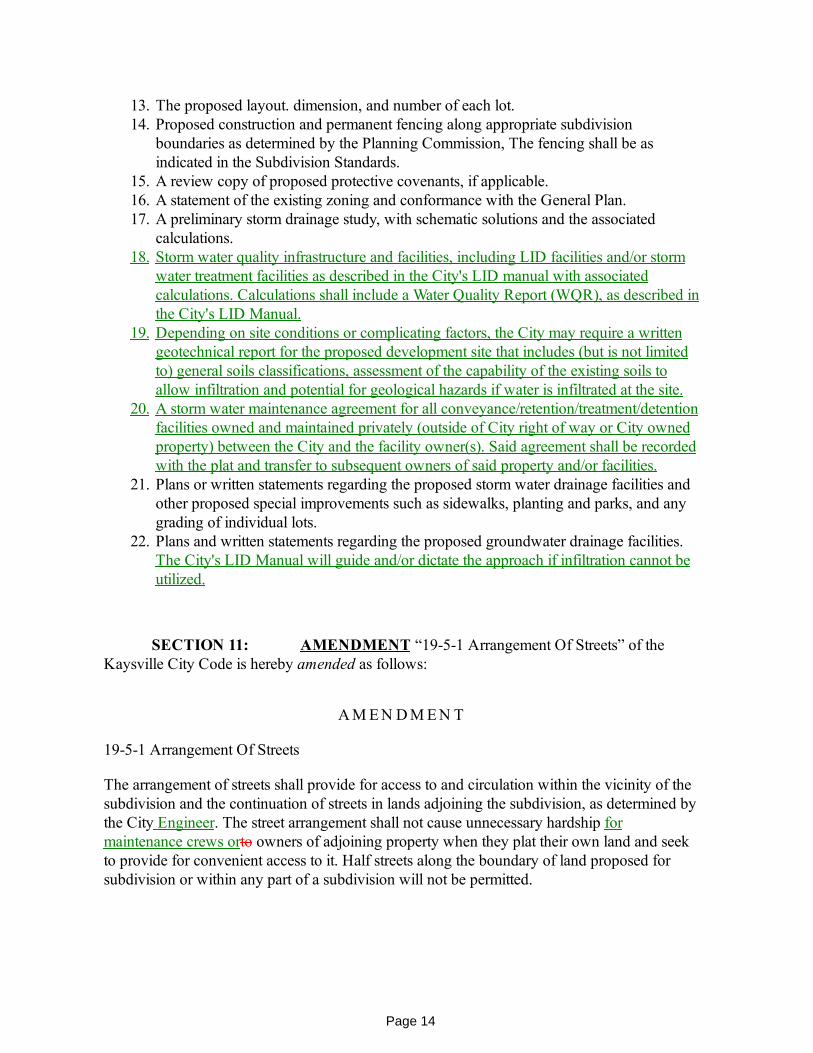
calculations. 18. Storm water quality infrastructure and facilities, including LID facilities and/or storm
water treatment facilities as described in the City's LID manual with associatedcalculations. Calculations shall include a Water Quality Report (WQR), as described inthe City's LID Manual.
19. Depending on site conditions or complicating factors, the City may require a writtengeotechnical report for the proposed development site that includes (but is not limitedto) general soils classifications, assessment of the capability of the existing soils toallow infiltration and potential for geological hazards if water is infiltrated at the site.
20. A storm water maintenance agreement for all conveyance/retention/treatment/detentionfacilities owned and maintained privately (outside of City right of way or City ownedproperty) between the City and the facility owner(s). Said agreement shall be recordedwith the plat and transfer to subsequent owners of said property and/or facilities.
21. Plans or written statements regarding the proposed storm water drainage facilities andother proposed special improvements such as sidewalks, planting and parks, and anygrading of individual lots.
22. Plans and written statements regarding the proposed groundwater drainage facilities.The City's LID Manual will guide and/or dictate the approach if infiltration cannot beutilized.
SECTION 11: AMENDMENT “19-5-1 Arrangement Of Streets” of theKaysville City Code is hereby amended as follows:
A M E N D M E N T
19-5-1 Arrangement Of Streets
The arrangement of streets shall provide for access to and circulation within the vicinity of thesubdivision and the continuation of streets in lands adjoining the subdivision, as determined bythe City Engineer. The street arrangement shall not cause unnecessary hardship formaintenance crews orto owners of adjoining property when they plat their own land and seekto provide for convenient access to it. Half streets along the boundary of land proposed forsubdivision or within any part of a subdivision will not be permitted.
Page 15
SECTION 12: AMENDMENT “19-5-2 Streets” of the Kaysville City Codeis hereby amended as follows:
A M E N D M E N T
19-5-2 Streets
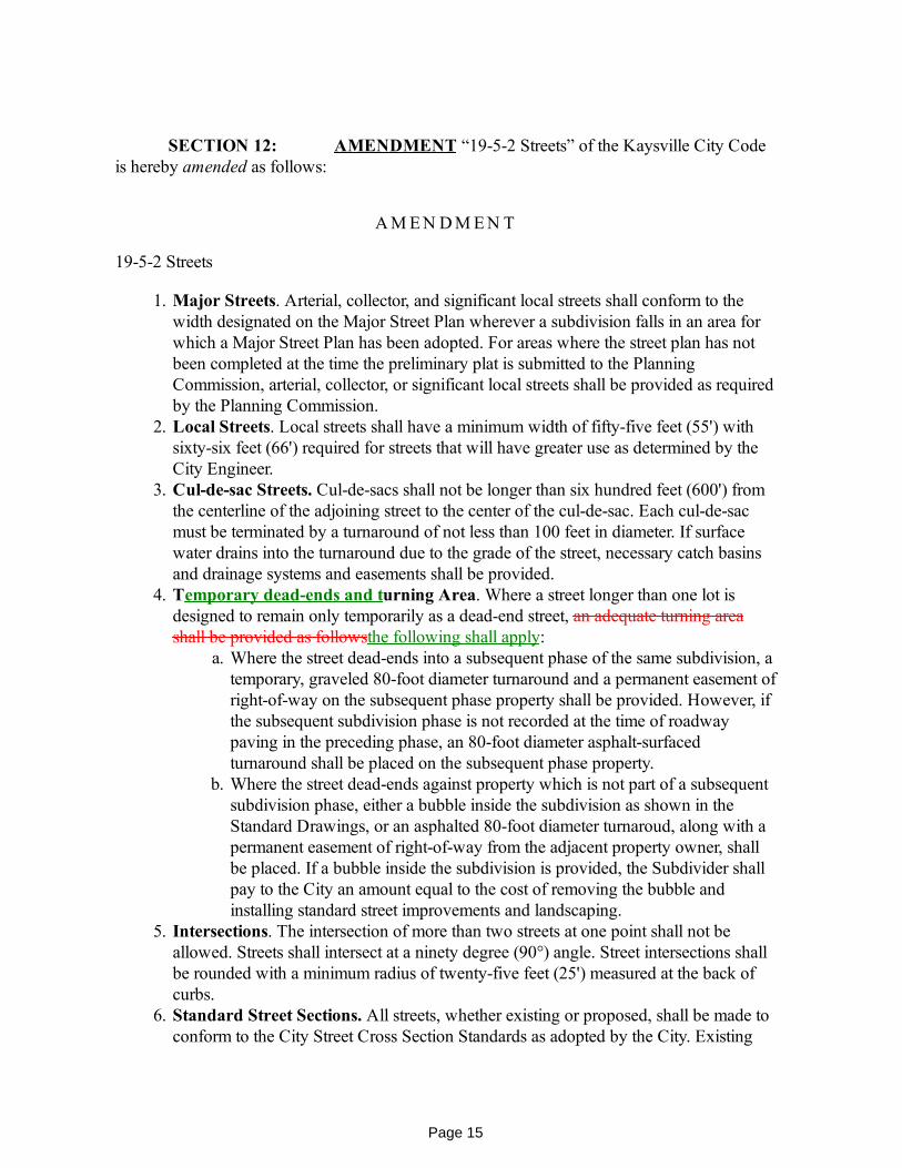
1. Major Streets. Arterial, collector, and significant local streets shall conform to thewidth designated on the Major Street Plan wherever a subdivision falls in an area forwhich a Major Street Plan has been adopted. For areas where the street plan has notbeen completed at the time the preliminary plat is submitted to the PlanningCommission, arterial, collector, or significant local streets shall be provided as requiredby the Planning Commission.
2. Local Streets. Local streets shall have a minimum width of fifty-five feet (55') withsixty-six feet (66') required for streets that will have greater use as determined by theCity Engineer.
3. Cul-de-sac Streets. Cul-de-sacs shall not be longer than six hundred feet (600') fromthe centerline of the adjoining street to the center of the cul-de-sac. Each cul-de-sacmust be terminated by a turnaround of not less than 100 feet in diameter. If surfacewater drains into the turnaround due to the grade of the street, necessary catch basinsand drainage systems and easements shall be provided.
4. Temporary dead-ends and turning Area. Where a street longer than one lot isdesigned to remain only temporarily as a dead-end street, an adequate turning areashall be provided as followsthe following shall apply:
a. Where the street dead-ends into a subsequent phase of the same subdivision, atemporary, graveled 80-foot diameter turnaround and a permanent easement ofright-of-way on the subsequent phase property shall be provided. However, ifthe subsequent subdivision phase is not recorded at the time of roadwaypaving in the preceding phase, an 80-foot diameter asphalt-surfacedturnaround shall be placed on the subsequent phase property.
b. Where the street dead-ends against property which is not part of a subsequentsubdivision phase, either a bubble inside the subdivision as shown in theStandard Drawings, or an asphalted 80-foot diameter turnaroud, along with apermanent easement of right-of-way from the adjacent property owner, shallbe placed. If a bubble inside the subdivision is provided, the Subdivider shallpay to the City an amount equal to the cost of removing the bubble andinstalling standard street improvements and landscaping.
5. Intersections. The intersection of more than two streets at one point shall not beallowed. Streets shall intersect at a ninety degree (90°) angle. Street intersections shallbe rounded with a minimum radius of twenty-five feet (25') measured at the back ofcurbs.
6. Standard Street Sections. All streets, whether existing or proposed, shall be made toconform to the City Street Cross Section Standards as adopted by the City. Existing

Page 16
streets shall be profiled and redesigned to full street width far enough beyond thesubdivision boundaries to drain and function properly.
7. Street Grades. Street grades shall not exceed the following percentages: on arterialstreets eight percent (8%); on local and collector streets ten percent (10%). Streetgrades near intersections shall be designed for adequate stopping and starting byadjusting grades on both sides of the intersection. Grades on all cul-de-sac streets shallbe a minimum of 1.0% and on all other streets shall be a minimum of 0.5% unlessspecifically authorized by the City Engineer. The cross slope of the street cross sectionis defined on the standard drawings. The maximum difference in curb elevations shallnot exceed one foot (1'), and then only with the approval of the City Engineer.
8. Alleys. Alleys shall have a minimum width of twenty-six feet (26'). Alleys may berequired in the rear of business lots, but will not be accepted in residential blocksexcept under unusual conditions where such alleys are considered necessary by thePlanning Commission.
9. Bridges. Design and construction of new bridges, whether essential for the overallcirculation plan of the City or required only to serve a subdivision, shall be approvedin advance by the City.
10. Protection Strips. Where subdivision streets parallel contiguous property of otherowners, the Subdivider may retain a protection strip of not less than one foot (1') inwidth between the street and adjacent property. Protection strips will be allowed onlyat the discretion of the City Council. after recommendation of the PlanningCommission, and in accordance with all City ordinances. An agreement with the City,approved by the City Attorney, shall be made by the Subdivider, contracting todedicate the one foot or larger protection strip free of charge to the City for streetpurposes upon payment by the present owners of the contiguous property to theSubdivider of a consideration named in the agreement. Such consideration is to beequal to the cost, at the time of the agreement, of the street improvements properlychargeable to the contiguous property, plus the value of the land from the right-of-wayline to the centerline of the street at the time of the agreement, together with interest ata fair rate from the time of agreement until the time of subdivision of such contiguousproperty. All charges to be associated with the protection strip, as well as the interestrate, shall be recorded as part of the aforementioned agreement. All property owned bythe Subdivider shall be included on both the preliminary and final plat.
11. Excavations and Fills. Subdivision development adjacent to the Great Salt Lake or itsnatural drainage channels, or within any marsh or wetlands which will result in anydischarge of excavated or fill materials. may require obtaining a permit from the U.S.Army Corps of Engineers prior to the issuance of local permits for the deposition of fillmaterial into any wetland or stream channel. This determination shall be made a part ofthe preliminary plat staff review.
12. Names and Numbers. Names of new streets shall not duplicate existing or planedstreet names unless a new street is a continuation of, or in the alignment with, theexisting or platted street. House numbers shall be assigned in accordance with theHouse Numbering System in effect in the City. All new streets shall be numbered ifthey are in alignment with the grid. They shall be named if not in alignment with the
Page 17
grid.
SECTION 13: AMENDMENT “19-6-2 Improvements Made Prior ToRecording Final Plat” of the Kaysville City Code is hereby amended as follows:
A M E N D M E N T
19-6-2 Improvements Made Prior To Recording Final Plat
The improvements required by the City, including the improvements in each and every openspace in the subdivision, shall be constructed and installed by the Subdivider and thereaftermaintained by the Subdivider until after the warranty period and acceptance by the City.Improvements shall not be installed or constructed until their location and specifications havebeen approved by the City Engineer. In cases where a pioneer developer or the City hasalready acquired easements or rights-of-way or installed improvements subject to the Fee forProject Improvements provisions of KCC 19-6-4, no recording of the final plat or issuance ofbuilding permits shall be permitted or allowed until the Fee for Project Improvementsprovisions of said Section have been satisfied.
SECTION 14: AMENDMENT “19-6-3 Improvements Required” of theKaysville City Code is hereby amended as follows:
A M E N D M E N T
19-6-3 Improvements Required
The improvements shall include all street improvements in front of all lots and along alldedicated streets to a connection with existing improvements of the same kind or to theboundary of the development nearest existing improvements. Layout must provide for furtherextension to adjacent development and to be compatible with the contour of the ground forproper drainage. All water lines, sewer lines, and any other buried conduit shall be installed tothe boundary lines of the development. The owner of any land located in or platted as asubdivision shall install the following improvements in compliance with the specificationscontained in the Specifications and Standard Drawings:
1. Sewage Collectiona. The Subdivider shall connect to the sanitary sewer and provide adequate
lateral lines to the property line of each lot. Such sewer connections andsubdivision sewer systems shall comply with the regulations and specificationsof, and shall be approved by, the applicable Sewer District and Kaysville City.All sewer lines must be extended across the entire frontage of all existing

Page 18
streets and to the boundary of the subdivision on all existing or proposed Citystreets.
b. Subdivisions using individual wastewater disposal systems are allowed in thearea of Kaysville City which is three hundred feet (300') or more west of andat an elevation that cannot flow to the western most sewer main of the CentralDavis Sewer District, if after review of all alternatives, the City Engineerdetermines that other alternatives are not reasonably available Suchsubdivisions shall comply with the following:
i. The Utah Department of Health Regulations for Individualwastewater Disposal Systems including a feasibility review andcertification by the Davis County Health Department.
ii. All lots shall be a minimum of two hundred ten thousand (210,000)square feet, be in the A-5 Heavy Agricultural District and complywith the provisions of that zone district.
iii. All systems shall be installed to accommodate and facilitateconnection to public sanitary sewer facilities when they becomeavailable (i.e., structure plumbing oriented to connect to sewer mains,street oriented to facilitate sewage flow).
iv. Execution and recording of an agreement and lien upon the property,in form and substance satisfactory to the City, that the owners will paytheir pro rata share of the costs of public sewer facilities to serve theproperty, when installed at the discretion of the City, includingdevelopment fees and street repairs.
2. Groundwater. The Subdivider shall protect the structures from groundwater by:a. Digging at least one test hole per acre or part thereof, at locations approved by
the City Engineer, and determining the depth of the groundwater table and thepermeability and percolation rate of the soils. These tests shall be performedby a qualified soils engineer at the Subdivider's expense. If a groundwaterdrainage system is installed to City standards, with a lateral provided to eachlot for a footing drain, this testing is not required.
b. Preparing a detailed groundwater plan for the subdivision. showing theminimum level of all floors and crawl spaces. If any floor or crawl space is tobe installed within one foot or below the groundwater table or where thepermeability and percolation rate of the soil is not adequate, the Subdividershall install a groundwater drainage system to City standards, with a lateralprovided to each lot for a footing drain.
c. Making improvements to adequately remove groundwater and preventgroundwater entry into buildings, including crawl spaces.
d. Preventing the discharge of surface water drainage into the groundwaterdrainage system.
3. Storm Water. A storm drainage plan has been prepared and is maintained byKaysville City and Davis County. The Subdivider shall implement the portion of thatplan applicable to the subdivision by:
a. Preparing a detailed drainage plan for the subdivision which is acceptable tothe City.

Page 19
b. Making sufficient improvements, such as storm drains, cross gutters, catchbasins, inlets, detention basins, LID facilities and other appurtenant structures,to adequately address the WQV and dispose of 10-year frequency stormrunoff within the subdivision and from adjacent properties. Said disposalsystem shall include the retention or treatment of the WQV, as detailed in theCity's LID Manual. Storm drains shall be not less than fifteen inches (15") indiameter and meet City standards and specifications.
c. Providing for restriction of the runoff from the subdivision to 0.20 cubic feetper second per acre per 10-year frequency rainfall event through one or moreof the following, at the direction of the City:
i. Conveyance (including easements) of the runoff to a regionaldetention/retentions/treatment site and paying the subdivisionsproportional share of the cost of the regional detention facility andconveyance to the main channel; or
ii. Dedicating land and constructing regionaldetention/retention/treatment within the subdivision and conveyanceto the main channel if said subdivision contains a proposed detentionsite. The Subdivider will may be compensated for a portion of the costof the regional detention and conveyance to the main channel for thatwhich is not the proportional share for the subdivision.; or
iii. Conveyance of the funoff to a site within the subdivision dedicatedand constructed for detention and/or retention.
d. If the subdivision is within one hundred feet (100') of a main channel,complying with all Davis County Flood Control requirements and beingapproved by Davis County.
e. The storm drainage plan is not intended to and may not eliminate periodicaccumulation of standing water on various lots in the subdivision duringperiods of heavy rainfall or runoff.
f. Unless otherwise directed or agreed to by the City Engineer, and infrastructurenot located in a City right of way that is installed or used for theconveyance/treatment/detention of storm water shall require a Storm WaterMaintenance Agreement to be approved by the Storm Water Official and shallbe recorded with the Davis County Recorder's Office, as per KCC 9-3d-8.
4. Culinary Water. The Subdivider shall install water lines to make the water supplyavailable to each lot within the subdivision, including laterals to the property line ofeach lot. The location and size of water mains shall be approved by the City Engineer.Unless otherwise directed by the City Engineer, Ssubdivision water lines shall be aminimum of eight inches (8") in diameter and service laterals shall be a minimum of3/4-inch in diameter. All water lines must be extended across the entire frontage of allexisting streets and to the boundary of the subdivision on all existing or proposed Citystreets.
5. Fire Hydrants. Fire hydrants shall be installed as required. Such fire hydrants shall beof the type, size, and number as directed by the City Engineeradopted by the City, andinstalled in such locations as approved by the City. A fire hydrant shall also be placed

Page 20
at the end of every cul-de-sac in which the water line dead-endsevery dead-end waterline, including the end of cul-de-sacs.
6. Irrigation Water. Unless located east of U.S. 89, pressure irrigation shall be providedto each lot in residential subdivisions.
a. All gravity flow ditches through which water will continue to flow within asubdivision after its completion, whether to serve as irrigation water and/orwaste flow to go from any adjacent property, shall remain in use and be pipedwith a minimum pipe size of at least 15 inches and shall be approved by theCity Engineer and irrigation provider. Irrigation ditches which will not carryirrigation water and/or waste flow shall be removed.
b. The Subdivider shall install pressure irrigation lines to make pressure irrigationavailable to each lot within the subdivision including laterals to the propertyline of each lot. All plans and specifications for pressure irrigation systemsshall be submitted to the City Engineer and irrigation provider. Such systemmust be approved by the City and irrigation provider. It shall be illegal for anyperson to connect together a culinary water system and a non-potable watersystem by any method.
c. The Subdivider shall comply with all the requirements of the pressureirrigation provider and furnish proof thereof to the City.
d. Unless otherwise directed by the City, irrigation water and infrastructure shallremain isolated from and independent of storm water infrastructure.
7. Street Grading and Surfacing. All streets whether existing or proposed, shall begraded and surfaced, including a Slurry Seal Type Ill applied on all new asphaltpavement in streets, in accordance with the standards and specifications of KaysvilleCity and the design for each street. Existing streets shall be modified to drain andfunction properly. Any pavement removed from existing streets shall be replacedwithin sixty (60) days of such removal.
8. Curbs and Gutters. Curbs and gutters shall be installed by the Subdivider on existingand proposed streets in accordance with all the appropriate specifications of KaysvilleCity. Curb and gutter shall be thirty inches (30") wide standard high back style, orstandard roll curb if recommended by the Planning Commission and approved by theCity Council, and shall be placed in six inches (6") of compacted untreated basecourse as foundation materials.
9. Street Drainage. Street drainage and drainage structures shall be required wheredeemed necessary in the opinion of the City Councilby the City Engineer. Drainagefacilities and structures shall address storm water quality to comly with State and EPAregulations and requirements, as outlined in the City's LID Manual.. afterrecommendation by the City Engineer.
10. Sidewalks. Sidewalks shall be installed according to the specifications of KaysvilleCity. Sidewalks shall be at least four feet (4') wide with four inches (4") of compacteduntreated base course material as foundation materials. Depth of sidewalks shall befour inches (4"). except at driveways, which shall be six inches (6").
11. Active Transportation Improvements. Subdivisions which include or are adjacent toan element of the Kaysville City Active Transportation Plan shall account for and

Page 21
install the applicable improvements including off street shared use paths and streetimprovements such as striping.
12. Telecommunications Conduit.Unless otherwise directed by the City Engineer,Cconduit for the purpose of housing telecommunications and internet infrastructureshall be installed in accordance with the Kaysville City Standard Drawings.
13. Driveway Approaches. All driveway approaches shall meet the followingspecifications:
Specification ResidentialType Commercial, Industrial,and Institutional
Minimum width 10 feet 10 feet
Maximum width 40 feet 40 feet
Minimum concrete thickness 6 inches 8 inches
Minimum base course thickness 6 inches 6 inches
Minimum distance between driveways 12feet 12 feet
Minimum distance to the point ofintersection of two property lines atany street intersection
20 feet 40 feet
14. Monuments. Permanent survey monuments shall be accurately set and established atthe intersections of centerlines of streets within the subdivision and intersections withcenterlines of existing streets and the beginning and ends of curves on centerlines orpoints of intersections or tangents. All permanent survey monuments shall remain inplace, or be reset at the Subdivider's expense, after curbs, gutter, and sidewalks areinstalled. Monuments shall be of a type specified in City standards, and all subdivisionplats shall be tied to a section corner or monument of record, as established by theDavis County Surveyor.
15. Electric Power Systema. The Subdivider shall pay the cost of electric S)'stem extensions and street
lights, installed by the City, to service the subdivision.b. The Subdivider shall be responsible to facilitate the extension of electrical
distribution lines by:i. Planning the installation of utilities to each lot or site to be served to
preclude conflict between other utilities and the electrical distributionlines.
ii. Scheduling and coordinating the actual installation of improvementsto allow adequate time for construction of electrical distribution lines.
iii. Notifying the Kaysville City Power Superintendent upon completionof adequate site preparation to allow installation of electricaldistribution lines.

Page 22
c. The Subdivider shall prepare the site for electrical distribution line installationbefore notifying Kaysville City to install said lines. Site preparation shallinclude but not be limited to:
i. Installation of curb and gutter indicating permanent grade.ii. Markers installed on curb indicating property lines.iii. The area extending from property side of sidewalk away from the
street for ten (10) feet leveled to final grade.
iv. Utilities installed less than four feet (4') below final grade notextending beyond the property line more than twelve inches (12").
d. The Subdivider shall provide the trenching and excavations for installation ofunderground facilities unless waived by the City.
e. The Subdivider shall back fill, compact, test, and guarantee the back fill ofexcavations for underground facilities installed.
16. Street Signs. The Subdivider shall pay the cost of traffic control, street identification,and other street signs, installed by the City, in accordance with City standards. Thecost will be charged to the Subdivider and shall be paid before the plat is recorded.The improvement assurance in the subdivision will not be released until after paymentof the costs incurred to install the necessary street signs has been made.
17. Fencing of Subdivision. A permanent solid board, metal chain link (with opaque slatsif required), masonry, or other similar fence not less than six feet (6') in height shall beinstalled prior to the start of building construction along all boundaries with propertiesadjacent to the subdivision where adjacent uses are found to be non-compatible by thePlanning Commission. In addition, temporary construction fencing shall be installedalong appropriate boundaries or where required to contain blowing refuse prior to thestart of building construction, as recommended by the City Engineer. The constructionfence shall remain in place until 90% of the lots are built on. The construction fenceshall be type ''D" field fence as given in the specifications. Upon installation of thepermanent fence by the Subdivider, and approval by Kaysville City, individualproperty owners shall assume full responsibility for maintenance of fences or portionsof fences constructed upon their property and shall not hold Kaysville City responsiblefor any and all defects of workmanship, maintenance, repair, and liabilities of anynature arising from the construction or intended use of said fences. In situations wherea temporary construction fence and a non-climbable permanent fence coincide, thenon-climbable permanent fence shall take the place of the temporary constructionfence and shall be constructed prior to the beginning of construction within thesubdivision.
18. Marking of Lots. Survey markers shall be placed at all lot corners and at lot boundarylocations to completely identify the lot boundaries on the ground. Lot corners shall beidentified with permanent plugs in the sidewalk or back of the curb or with a metalpipe or rod driven into the ground if sidewalks or curbs are not next to the lotboundary. All lot corners and lot boundaries shall be marked prior to the issuance ofbuilding permits, after the completion of all subdivision improvements and duringbuilding construction and inspections. It shall be the responsibility of the lot owner toinsure that all lot corner and boundary markers are in place. The City is not responsible

Page 23
AYE NAY ABSENT ABSTAIN
Council Member Adams
Council Member Barber
Council Member Blackham
Council Member Lortz
Council Member Tran
to replace survey stakes or markers.19. Highway Noise Abatement. Highway noise abatement, as determined through
environmental studies and engineering analysis and approved by the PlanningCommission. shall be provided in all residential subdivisions within three hundred feet(300') of a freeway or principal arterial. Noise abatement may include distance of noisesensitive uses from noise sources, landscaping, earth berms, and other mitigation. TheSubdivider shall pay the entire cost of any noise abatement studies and noiseabatement facilities.
SECTION 15: REPEALER CLAUSE All ordinances or resolutions or partsthereof, which are in conflict herewith, are hereby repealed.
SECTION 16: SEVERABILITY CLAUSE Should any part or provision ofthis Ordinance be declared by the courts to be unconstitutional or invalid, such decision shallnot affect the validity of the Ordinances a whole or any part thereof other than the part sodeclared to be unconstitutional or invalid.
SECTION 17: EFFECTIVE DATE This Ordinance shall be in full forceand effect 2 weeks from the date of passage by the Kaysville City Council.
PASSED AND ADOPTED BY THE KAYSVILLE CITY COUNCIL_______________________________.
Presiding O fficer Attest
Katie Witt, Mayor, Kaysville City Annemarie Plaizier, City RecorderKaysville City

ORDINANCE __-__-__
AN ORDINANCE AMENDING THE DEVELOPMENT GUIDELINES AND DESIGN STANDARDS
WHEREAS, Kaysville City currently maintains Development Guidelines and Design Standards (hereinafter "Guidelines") for the purpose of assisting developers in meeting the current engineering standards required by the City; and
WHEREAS, the Guidelines change or need to be updated from time to time, as required by State Law; and
WHEREAS, Kaysville City Staff has reviews the existing Guidelines from time to time as determined necessary; and
WHEREAS, Utah State Code requires the approval of those Guidelines by ordinance; and
WHEREAS, the City Engineer and the Community Development Staff have reviewed the current Guidelines and have determined that the current Guidelines needed to be updated and amended; and
WHEREAS, City Staff has determined, pursuant to the above referenced ordinance, that it is in the best interest of the City to adopt and amend the Guidelines; and
WHEREAS, the City Council has determined that it is in the best interest of the City to adopt and amend the Guidelines.
NOW, THEREFORE, BE IT ORDAINED BY THE CITY COUNCIL OF LAYTON, UTAH:
SECTION I: Repealer. If any provisions of the Development Guidelines and Design Standards previously adopted are inconsistent herewith they are hereby repealed.
SECTION II: Enactment. The following provisions of the Development Guidelines and Design Standards are hereby as depicted on the accompanying drawings which are attached hereto and incorporated herein by this reference.
SECTION III: LID APPROVAL. The Low Impact Development Manual 2021 is also hereby approved as a guideline for future projects.
SECTION IV: Severability. If any section, subsection, sentence, clause or phrase of this ordinance is declared invalid or unconstitutional by a court of competent jurisdiction, said portion shall be severed and such declaration shall not affect the validity of the remainder of this ordinance.
SECTION V: Effective Date. This ordinance being necessary for the peace, health and safety of the City, shall become effective immediately upon posting.
PASSED AND ADOPTED by the City Council of Kaysville, Utah, this _____ day of ___________________, 20___.
_______________________________________
_ Katie Witt, Mayor
ATTEST: ________________________________________ Annemarie Plaizier, City Recorder
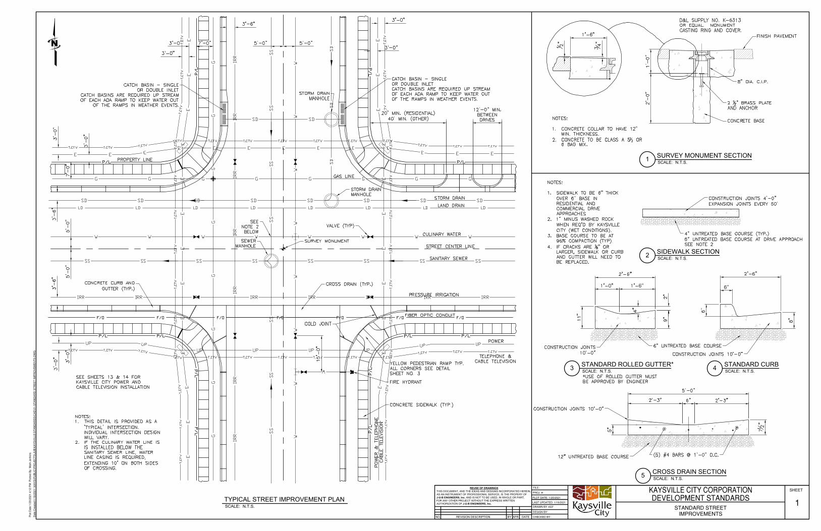
REUSE OF DRAWINGSTHIS DOCUMENT, AND THE IDEAS AND DESIGNS INCORPORATED HEREIN,AS AN INSTRUMENT OF PROFESSIONAL SERVICE, IS THE PROPERY OFJ-U-B ENGINEERS, Inc. AND IS NOT TO BE USED, IN WHOLE OR PART,FOR ANY OTHER PROJECT WITHOUT THE EXPRESS WRITTENAUTHORIZATION OF J-U-B ENGINEERS, Inc.
REVISION DESCRIPTIONNO.
PROJ. #:
DESIGN BY:
DRAWN BY:
CHECKED BY:APR. DATEBY
SHEETFILE:
LAST UPDATED: 1/19/2021
PLOT DATE: 1/20/2021
Plo
t Dat
e:1/
20/2
021
4:12
PM
Plo
tted
By:
Mar
k Je
nkin
s
Dat
e C
reat
ed:1
/19/
2021
\\K
AY
S\P
UB
LIC
\PR
OJE
CT
S\J
UB
\KA
YS
VIL
LE\S
TA
ND
AR
DS
\CA
D\0
1-S
TA
ND
AR
D S
TR
EE
T IM
PR
OV
EM
EN
TS
.DW
G
KAYSVILLE CITY CORPORATIONDEVELOPMENT STANDARDS
STANDARD STREETIMPROVEMENTS
1KEF
SCALE:2 SIDEWALK SECTION N.T.S.
N
SCALE:3 STANDARD ROLLED GUTTER* N.T.S. SCALE:4 STANDARD CURB
N.T.S.
SCALE:5 CROSS DRAIN SECTION N.T.S.
SCALE:1 SURVEY MONUMENT SECTION N.T.S.
SCALE:TYPICAL STREET IMPROVEMENT PLAN
N.T.S.
AutoCAD SHX Text
SEWER MANHOLE
AutoCAD SHX Text
SURVEY MONUMENT
AutoCAD SHX Text
VALVE (TYP)
AutoCAD SHX Text
STORM DRAIN MANHOLE
AutoCAD SHX Text
STORM DRAIN MANHOLE
AutoCAD SHX Text
FIRE HYDRANT
AutoCAD SHX Text
CONCRETE SIDEWALK (TYP.)
AutoCAD SHX Text
POWER & TELEPHONE CABLE TELEVISION
AutoCAD SHX Text
YELLOW PEDESTRIAN RAMP TYP. ALL CORNERS SEE DETAIL SHEET NO. 3
AutoCAD SHX Text
POWER
AutoCAD SHX Text
CROSS DRAIN (TYP.)
AutoCAD SHX Text
CONCRETE CURB AND GUTTER (TYP.)
AutoCAD SHX Text
COLD JOINT
AutoCAD SHX Text
SEE SHEETS 13 & 14 FOR KAYSVILLE CITY POWER AND CABLE TELEVISION INSTALLATION
AutoCAD SHX Text
PROPERTY LINE
AutoCAD SHX Text
STORM DRAIN
AutoCAD SHX Text
CULINARY WATER
AutoCAD SHX Text
SANITARY SEWER
AutoCAD SHX Text
PRESSURE IRRIGATION
AutoCAD SHX Text
GAS LINE
AutoCAD SHX Text
STREET CENTER LINE
AutoCAD SHX Text
LAND DRAIN
AutoCAD SHX Text
TELEPHONE & CABLE TELEVISION
AutoCAD SHX Text
FIBER OPTIC CONDUIT
AutoCAD SHX Text
NOTES: 1. THIS DETAIL IS PROVIDED AS A THIS DETAIL IS PROVIDED AS A 'TYPICAL' INTERSECTION. INDIVIDUAL INTERSECTION DESIGN WILL VARY. 2. IF THE CULINARY WATER LINE IS IF THE CULINARY WATER LINE IS IS INSTALLED BELOW THE SANITARY SEWER LINE, WATER LINE CASING IS REQUIRED, EXTENDING 10' ON BOTH SIDES OF CROSSING.
AutoCAD SHX Text
SEE NOTE 2 BELOW
AutoCAD SHX Text
CATCH BASIN - SINGLE OR DOUBLE INLET CATCH BASINS ARE REQUIRED UP STREAM OF EACH ADA RAMP TO KEEP WATER OUT OF THE RAMPS IN WEATHER EVENTS.
AutoCAD SHX Text
CATCH BASIN - SINGLE OR DOUBLE INLET CATCH BASINS ARE REQUIRED UP STREAM OF EACH ADA RAMP TO KEEP WATER OUT OF THE RAMPS IN WEATHER EVENTS.
AutoCAD SHX Text
6" UNTREATED BASE COURSE
AutoCAD SHX Text
NOTES: 1. SIDEWALK TO BE 6" THICK SIDEWALK TO BE 6" THICK OVER 6" BASE IN RESIDENTIAL AND COMMERCIAL DRIVE APPROACHES 2. 1" MINUS WASHED ROCK 1" MINUS WASHED ROCK WHEN REQ'D BY KAYSVILLE CITY (WET CONDITIONS). 3. BASE COURSE TO BE AT BASE COURSE TO BE AT 96% COMPACTION (TYP). 4. IF CRACKS ARE " OR IF CRACKS ARE " OR 18" OR LARGER, SIDEWALK OR CURB AND GUTTER WILL NEED TO BE REPLACED.
AutoCAD SHX Text
12" UNTREATED BASE COURSE
AutoCAD SHX Text
CONSTRUCTION JOINTS 10'-0"
AutoCAD SHX Text
CONSTRUCTION JOINTS 10'-0"
AutoCAD SHX Text
CONSTRUCTION JOINTS 10'-0"
AutoCAD SHX Text
4" UNTREATED BASE COURSE (TYP.) 6" UNTREATED BASE COURSE AT DRIVE APPROACH SEE NOTE 2
AutoCAD SHX Text
CONSTRUCTION JOINTS 4'-0" EXPANSION JOINTS EVERY 50'
AutoCAD SHX Text
*USE OF ROLLED GUTTER MUST BE APPROVED BY ENGINEER
AutoCAD SHX Text
NOTES: 1. CONCRETE COLLAR TO HAVE 12" CONCRETE COLLAR TO HAVE 12" MIN. THICKNESS. 2. CONCRETE TO BE CLASS A 5 OR CONCRETE TO BE CLASS A 5 OR 12 OR 6 BAG MIX.
AutoCAD SHX Text
CONCRETE BASE
AutoCAD SHX Text
2 " BRASS PLATE 12" BRASS PLATE AND ANCHOR
AutoCAD SHX Text
8" DIA. C.I.P.
AutoCAD SHX Text
D&L SUPPLY NO. K-6313 OR EQUAL. MONUMENT CASTING RING AND COVER.
AutoCAD SHX Text
FINISH PAVEMENT
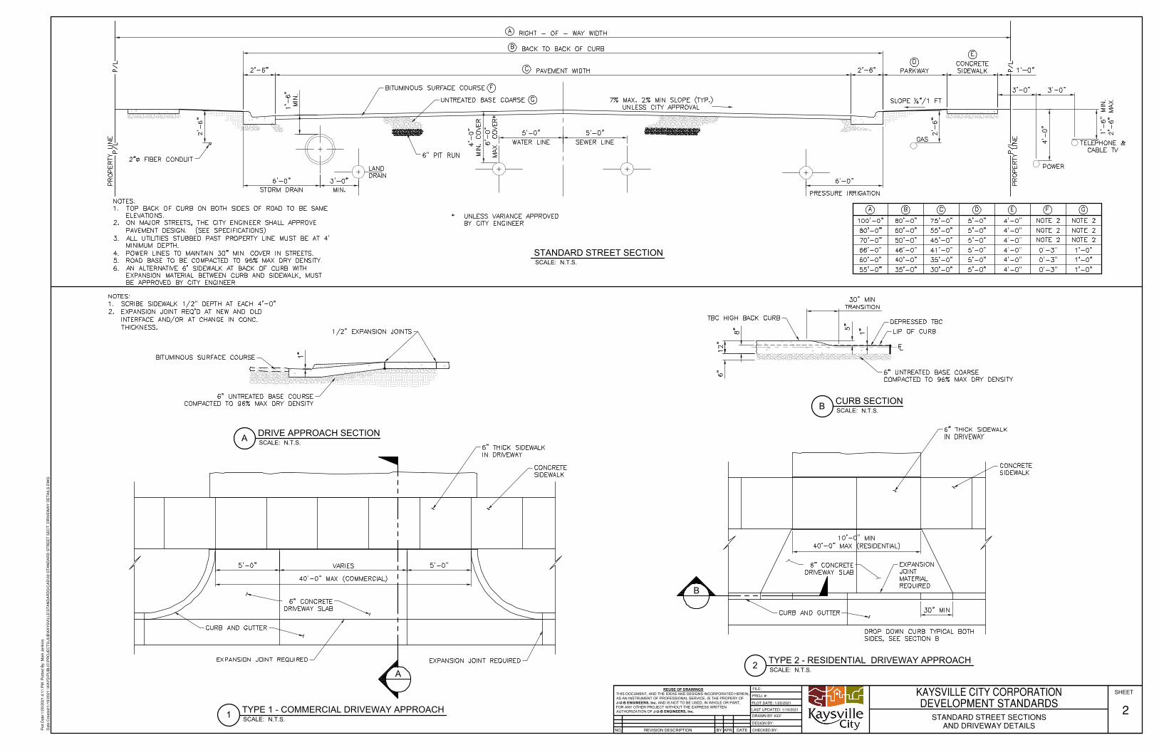
A
B
REUSE OF DRAWINGSTHIS DOCUMENT, AND THE IDEAS AND DESIGNS INCORPORATED HEREIN,AS AN INSTRUMENT OF PROFESSIONAL SERVICE, IS THE PROPERY OFJ-U-B ENGINEERS, Inc. AND IS NOT TO BE USED, IN WHOLE OR PART,FOR ANY OTHER PROJECT WITHOUT THE EXPRESS WRITTENAUTHORIZATION OF J-U-B ENGINEERS, Inc.
REVISION DESCRIPTIONNO.
PROJ. #:
DESIGN BY:
DRAWN BY:
CHECKED BY:APR. DATEBY
SHEETFILE:
LAST UPDATED: 1/19/2021
PLOT DATE: 1/20/2021
Plo
t Dat
e:1/
20/2
021
4:11
PM
Plo
tted
By:
Mar
k Je
nkin
s
Dat
e C
reat
ed:1
/19/
2021
\\K
AY
S\P
UB
LIC
\PR
OJE
CT
S\J
UB
\KA
YS
VIL
LE\S
TA
ND
AR
DS
\CA
D\0
2-S
TA
ND
AR
D S
TR
EE
T S
EC
T_D
RIV
EW
AY
DE
TA
ILS
.DW
G
KAYSVILLE CITY CORPORATIONDEVELOPMENT STANDARDS
STANDARD STREET SECTIONSAND DRIVEWAY DETAILS
2KEF
SCALE:B CURB SECTION N.T.S.
SCALE:2 TYPE 2 - RESIDENTIAL DRIVEWAY APPROACH N.T.S.
SCALE:STANDARD STREET SECTION
N.T.S.
SCALE:1 TYPE 1 - COMMERCIAL DRIVEWAY APPROACH N.T.S.
SCALE:A DRIVE APPROACH SECTION N.T.S.
AutoCAD SHX Text
6" THICK SIDEWALK IN DRIVEWAY
AutoCAD SHX Text
CURB AND GUTTER
AutoCAD SHX Text
6" CONCRETE DRIVEWAY SLAB
AutoCAD SHX Text
CONCRETE SIDEWALK
AutoCAD SHX Text
BITUMINOUS SURFACE COURSE
AutoCAD SHX Text
6" UNTREATED BASE COURSE COMPACTED TO 96% MAX DRY DENSITY
AutoCAD SHX Text
1/2" EXPANSION JOINTS
AutoCAD SHX Text
NOTES: 1. SCRIBE SIDEWALK 1/2" DEPTH AT EACH 4'-0" SCRIBE SIDEWALK 1/2" DEPTH AT EACH 4'-0" 2. EXPANSION JOINT REQ'D AT NEW AND OLD EXPANSION JOINT REQ'D AT NEW AND OLD INTERFACE AND/OR AT CHANGE IN CONC. THICKNESS.
AutoCAD SHX Text
EXPANSION JOINT REQUIRED
AutoCAD SHX Text
EXPANSION JOINT REQUIRED
AutoCAD SHX Text
6" THICK SIDEWALK IN DRIVEWAY
AutoCAD SHX Text
CURB AND GUTTER
AutoCAD SHX Text
CONCRETE SIDEWALK
AutoCAD SHX Text
DROP DOWN CURB TYPICAL BOTH SIDES, SEE SECTION B
AutoCAD SHX Text
6" UNTREATED BASE COARSE COMPACTED TO 96% MAX DRY DENSITY
AutoCAD SHX Text
DEPRESSED TBC
AutoCAD SHX Text
LIP OF CURB
AutoCAD SHX Text
TBC HIGH BACK CURB
AutoCAD SHX Text
AutoCAD SHX Text
EXPANSION JOINT MATERIAL REQUIRED
AutoCAD SHX Text
PRESSURE IRRIGATION
AutoCAD SHX Text
PROPERTY LINE
AutoCAD SHX Text
SLOPE "/1 FT14"/1 FT
AutoCAD SHX Text
GAS
AutoCAD SHX Text
POWER
AutoCAD SHX Text
7% MAX. 2% MIN SLOPE (TYP.) UNLESS CITY APPROVAL
AutoCAD SHX Text
UNTREATED BASE COARSE
AutoCAD SHX Text
BITUMINOUS SURFACE COURSE
AutoCAD SHX Text
WATER LINE
AutoCAD SHX Text
4'-0"
AutoCAD SHX Text
SEWER LINE
AutoCAD SHX Text
MIN. COVER
AutoCAD SHX Text
MIN.
AutoCAD SHX Text
LAND DRAIN
AutoCAD SHX Text
STORM DRAIN
AutoCAD SHX Text
PROPERTY LINE
AutoCAD SHX Text
100'-0"
AutoCAD SHX Text
80'-0"
AutoCAD SHX Text
75'-0"
AutoCAD SHX Text
5'-0"
AutoCAD SHX Text
4'-0"
AutoCAD SHX Text
NOTE 2
AutoCAD SHX Text
NOTE 2
AutoCAD SHX Text
80'-0"
AutoCAD SHX Text
60'-0"
AutoCAD SHX Text
55'-0"
AutoCAD SHX Text
5'-0"
AutoCAD SHX Text
4'-0"
AutoCAD SHX Text
NOTE 2
AutoCAD SHX Text
NOTE 2
AutoCAD SHX Text
70'-0"
AutoCAD SHX Text
50'-0"
AutoCAD SHX Text
45'-0"
AutoCAD SHX Text
5'-0"
AutoCAD SHX Text
4'-0"
AutoCAD SHX Text
NOTE 2
AutoCAD SHX Text
NOTE 2
AutoCAD SHX Text
66'-0"
AutoCAD SHX Text
46'-0"
AutoCAD SHX Text
41'-0"
AutoCAD SHX Text
5'-0"
AutoCAD SHX Text
4'-0"
AutoCAD SHX Text
0'-3"
AutoCAD SHX Text
1'-0"
AutoCAD SHX Text
60'-0"
AutoCAD SHX Text
40'-0"
AutoCAD SHX Text
35'-0"
AutoCAD SHX Text
5'-0"
AutoCAD SHX Text
4'-0"
AutoCAD SHX Text
0'-3"
AutoCAD SHX Text
1'-0"
AutoCAD SHX Text
55'-0"
AutoCAD SHX Text
35'-0"
AutoCAD SHX Text
30'-0"
AutoCAD SHX Text
5'-0"
AutoCAD SHX Text
4'-0"
AutoCAD SHX Text
0'-3"
AutoCAD SHX Text
1'-0"
AutoCAD SHX Text
TELEPHONE & CABLE TV
AutoCAD SHX Text
1'-6" MIN. 2'-6" MAX.
AutoCAD SHX Text
2" FIBER CONDUIT
AutoCAD SHX Text
6'-0"
AutoCAD SHX Text
MAX. COVER*
AutoCAD SHX Text
*UNLESS VARIANCE APPROVED UNLESS VARIANCE APPROVED BY CITY ENGINEER
AutoCAD SHX Text
6" PIT RUN
AutoCAD SHX Text
NOTES: 1. TOP BACK OF CURB ON BOTH SIDES OF ROAD TO BE SAME TOP BACK OF CURB ON BOTH SIDES OF ROAD TO BE SAME ELEVATIONS. 2. ON MAJOR STREETS, THE CITY ENGINEER SHALL APPROVE ON MAJOR STREETS, THE CITY ENGINEER SHALL APPROVE PAVEMENT DESIGN. (SEE SPECIFICATIONS) 3. ALL UTILITIES STUBBED PAST PROPERTY LINE MUST BE AT 4' ALL UTILITIES STUBBED PAST PROPERTY LINE MUST BE AT 4' MINIMUM DEPTH. 4. POWER LINES TO MAINTAIN 30" MIN. COVER IN STREETS. POWER LINES TO MAINTAIN 30" MIN. COVER IN STREETS. 5. ROAD BASE TO BE COMPACTED TO 96% MAX DRY DENSITY. ROAD BASE TO BE COMPACTED TO 96% MAX DRY DENSITY. 6. AN ALTERNATIVE 6' SIDEWALK AT BACK OF CURB WITH AN ALTERNATIVE 6' SIDEWALK AT BACK OF CURB WITH EXPANSION MATERIAL BETWEEN CURB AND SIDEWALK, MUST BE APPROVED BY CITY ENGINEER.
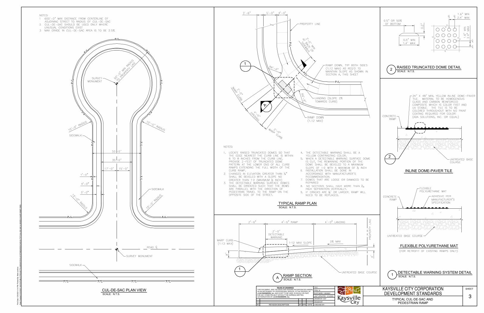
1A
1
2
REUSE OF DRAWINGSTHIS DOCUMENT, AND THE IDEAS AND DESIGNS INCORPORATED HEREIN,AS AN INSTRUMENT OF PROFESSIONAL SERVICE, IS THE PROPERY OFJ-U-B ENGINEERS, Inc. AND IS NOT TO BE USED, IN WHOLE OR PART,FOR ANY OTHER PROJECT WITHOUT THE EXPRESS WRITTENAUTHORIZATION OF J-U-B ENGINEERS, Inc.
REVISION DESCRIPTIONNO.
PROJ. #:
DESIGN BY:
DRAWN BY:
CHECKED BY:APR. DATEBY
SHEETFILE:
LAST UPDATED: 12/3/2020
PLOT DATE: 1/20/2021
Plo
t Dat
e:1/
20/2
021
4:14
PM
Plo
tted
By:
Mar
k Je
nkin
s
Dat
e C
reat
ed:1
2/3/
2020
\\K
AY
S\P
UB
LIC
\PR
OJE
CT
S\J
UB
\KA
YS
VIL
LE\S
TA
ND
AR
DS
\CA
D\0
3-T
YP
CU
L-D
E-S
AC
& W
HE
ELC
HA
IR R
AM
P.D
WG
KAYSVILLE CITY CORPORATIONDEVELOPMENT STANDARDS
TYPICAL CUL-DE-SAC AND PEDESTRIAN RAMP
3KEF
SCALE:A RAMP SECTION N.T.S.
SCALE:2 RAISED TRUNCATED DOME DETAIL N.T.S.
SCALE:1 DETECTABLE WARNING SYSTEM DETAIL N.T.S.
FLEXIBLE POLYURETHANE MAT
SCALE:CUL-DE-SAC PLAN VIEW
N.T.S.
SCALE:TYPICAL RAMP PLAN
N.T.S.
INLINE DOME-PAVER TILE
AutoCAD SHX Text
SURVEY MONUMENT
AutoCAD SHX Text
SIDEWALK
AutoCAD SHX Text
SIDEWALK
AutoCAD SHX Text
SURVEY MONUMENT
AutoCAD SHX Text
SIDEWALK
AutoCAD SHX Text
ROAD
AutoCAD SHX Text
NOTES: 1. 600'-0" MAX DISTANCE FROM CENTERLINE OF 600'-0" MAX DISTANCE FROM CENTERLINE OF ADJOINING STREET TO RADIUS OF CUL-DE-SAC. 2. CUL-DE-SAC SHOULD BE USED ONLY WHERE CUL-DE-SAC SHOULD BE USED ONLY WHERE UNUSUAL CONDITIONS EXIST. 3. MAX GRADE IN CUL-DE-SAC AREA IS TO BE 2.5%.MAX GRADE IN CUL-DE-SAC AREA IS TO BE 2.5%.
AutoCAD SHX Text
WARP CURB (1:12 MAX)
AutoCAD SHX Text
PROPERTY LINE
AutoCAD SHX Text
UNTREATED BASE COURSE
AutoCAD SHX Text
1:12 MAX SLOPE
AutoCAD SHX Text
2% MAX
AutoCAD SHX Text
RAMP DOWN (1:12 MAX)
AutoCAD SHX Text
LANDING (SLOPE 2% TOWARDS CURB)
AutoCAD SHX Text
RAMP DOWN, TYP BOTH SIDES (1:12 MAX) AS REQ'D TO MAINTAIN SLOPE AS SHOWN IN SECTION A, THIS SHEET
AutoCAD SHX Text
PROPERTY LINE
AutoCAD SHX Text
NOTES: 1. LOCATE RAISED TRUNCATED DOMES SO THAT LOCATE RAISED TRUNCATED DOMES SO THAT THE EDGE NEAREST THE CURB LINE IS WITHIN 6 TO 8 INCHES FROM THE CURB LINE. PROVIDE 2-FEET OF TRUNCATED DOME PATTERN AT THE LOWER END OF ALL CURB RAMPS EXTENDING THE FULL WIDTH OF THE CURB RAMP. 2. CHANGES IN ELEVATION GREATER THAN " CHANGES IN ELEVATION GREATER THAN " 14" SHALL BE BEVELED WITH A SLOPE NO GREATER THAN 1:2 (MAXIMUM INCH). 12 INCH). 3. THE DETECTABLE WARNING SURFACE DOMES THE DETECTABLE WARNING SURFACE DOMES SHALL BE ORIENTED SUCH THAT THE ROWS ARE PARALLEL WITH THE DIRECTION OF PEDESTRIAN TRAVEL TO THE RAMP ON THE OPPOSITE SIDE OF THE STREET. 4. THE DETECTABLE WARNING SHALL BE A THE DETECTABLE WARNING SHALL BE A YELLOW CONTRASTING COLOR. 5. WHEN A DETECTABLE WARNING SURFACE DOME WHEN A DETECTABLE WARNING SURFACE DOME IS CUT, THE REMAINING PORTION OF THE DOME SHALL BE BEVELED TO A MAXIMUM SLOPE OF 1:2 WITH A MAXIMUM OF INCH. 12 INCH. 6. INSTALLATION SHALL BE DONE IN INSTALLATION SHALL BE DONE IN ACCORDANCE WITH MANUFACTURER'S RECOMMENDATION. 7. DOMES THAT ARE LOOSE OR DAMAGED TO BE DOMES THAT ARE LOOSE OR DAMAGED TO BE REPAIRED. 8. NO SECTIONS SHALL HAVE MORE THAN NO SECTIONS SHALL HAVE MORE THAN 116INCH SEPARATION VERTICALLY. 9. IF CRACKS ARE " OR LARGER, RAMP WILL IF CRACKS ARE " OR LARGER, RAMP WILL 18" OR LARGER, RAMP WILL NEED TO BE REPLACED.
AutoCAD SHX Text
AutoCAD SHX Text
AutoCAD SHX Text
AutoCAD SHX Text
AutoCAD SHX Text
CONCRETE RAMP
AutoCAD SHX Text
24" X 48" MIN. YELLOW INLINE DOME-PAVER TILE. MATERIAL TO BE HOMOGENOUS GLASS AND CARBON REINFORCED COMPOSITE WHICH IS COLOR FAST AND UV STABLE. THE TILE IS TO BE COLORED THROUGHOUT WITH NO PAINT COATING REQUIRED FOR COLOR. (ADA SOLUTIONS, INC. OR EQUAL)
AutoCAD SHX Text
UNTREATED BASE COURSE
AutoCAD SHX Text
CONCRETE RAMP
AutoCAD SHX Text
FLEXIBLE POLYURETHANE MAT
AutoCAD SHX Text
ADHESIVE PER MANUFACTURER'S SPECIFICATION
AutoCAD SHX Text
UNTREATED BASE COURSE
AutoCAD SHX Text
(FOR RETROFIT OF EXISTING RAMPS ONLY)

KAYSVILLE CITY CORPORATION WATER SERVICE INFORMATIONSERVICE
SIZEMETER BOX
SIZE TYPE OF MATERIAL FOR METER BOX WATER METER CONNECTIONTYPE BYPASS DIST. BETWEEN
FLANGE
REUSE OF DRAWINGSTHIS DOCUMENT, AND THE IDEAS AND DESIGNS INCORPORATED HEREIN,AS AN INSTRUMENT OF PROFESSIONAL SERVICE, IS THE PROPERY OFJ-U-B ENGINEERS, Inc. AND IS NOT TO BE USED, IN WHOLE OR PART,FOR ANY OTHER PROJECT WITHOUT THE EXPRESS WRITTENAUTHORIZATION OF J-U-B ENGINEERS, Inc.
REVISION DESCRIPTIONNO.
PROJ. #:
DESIGN BY:
DRAWN BY:
CHECKED BY:APR. DATEBY
SHEETFILE:
LAST UPDATED: 12/3/2020
PLOT DATE: 1/20/2021
Plo
t Dat
e:1/
20/2
021
4:21
PM
Plo
tted
By:
Mar
k Je
nkin
s
Dat
e C
reat
ed:1
2/3/
2020
\\K
AY
S\P
UB
LIC
\PR
OJE
CT
S\J
UB
\KA
YS
VIL
LE\S
TA
ND
AR
DS
\CA
D\0
4-W
AT
ER
SE
RV
ICE
CO
NN
EC
TIO
N D
ET
AIL
S.D
WG
KAYSVILLE CITY CORPORATIONDEVELOPMENT STANDARDS
TYPICAL WATER SERVICE CONNECTIONDETAILS
4KEF
SCALE:2 REDUCED PRESSURE BACKFLOW PREVENTION ASSEMBLY N.T.S.
SCALE:3 TYPICAL WATER CONNECTION N.T.S.
SCALE:1 TYPICAL FLANGED METER SETTER WATER CONNECTION N.T.S.
AutoCAD SHX Text
STANDARD 4'-0" SIDEWALK
AutoCAD SHX Text
CONCRETE MANHOLE SECTION WITH FLAT LID, CENTERED ACCESS. MIN HEIGHT 2'-0"
AutoCAD SHX Text
12" GRAVEL FOUNDATION REQUIRED
AutoCAD SHX Text
12" CONCRETE BLOCKS
AutoCAD SHX Text
DOUBLE CHECK VALVE
AutoCAD SHX Text
CAST IRON COVER D&L SUPPLY 2240. COVER TO BE LEVEL WITH TBC
AutoCAD SHX Text
STANDARD CURB & GUTTER
AutoCAD SHX Text
FLANGE METER SETTER W/ CHECK VALVE
AutoCAD SHX Text
VALVED BYPASS, NOT METERED
AutoCAD SHX Text
BLUE POLY PIPE
AutoCAD SHX Text
COMPRESSION CORP. STOP (MUELLER, FORD OR APPROVED EQUAL)
AutoCAD SHX Text
CULINARY WATER MAIN
AutoCAD SHX Text
BLUE POLY PIPE
AutoCAD SHX Text
CULINARY WATER MAIN
AutoCAD SHX Text
COMPRESSION CORP. STOP (MUELLER, FORD OR APPROVED EQUAL)
AutoCAD SHX Text
BRONZE DOUBLE STRAP SERVICE SADDLE FOR AC. O.D. CONTROLLED BRONZE SADDLE FOR PVC.
AutoCAD SHX Text
ASPHALT ROAD SURFACE
AutoCAD SHX Text
STANDARD CURB & GUTTER
AutoCAD SHX Text
CAST IRON COVER, D&L SUPPLY 2240. COVER TO BE " ABOVE TBC 38" ABOVE TBC (2" HOLE IN LID)
AutoCAD SHX Text
STANDARD 4'-0" SIDEWALK
AutoCAD SHX Text
CHECK VALVE
AutoCAD SHX Text
METER TO BE SUPPLIED AND INSTALLED BY CITY
AutoCAD SHX Text
PRECAST CONCRETE, OR DOUBLE WALL POLYETHYLENE METER BOX
AutoCAD SHX Text
COMPRESSION FITTINGS
AutoCAD SHX Text
BLUE POLY PIPE
AutoCAD SHX Text
LOCKING ANGLE COPPER-SETTER (MUELLER H-1434-2A OR APPROVED EQUAL) WITH RISER AS APPROPRIATE.
AutoCAD SHX Text
UNTREATED BASE COURSE
AutoCAD SHX Text
TAP ON AC AND PVC PIPE
AutoCAD SHX Text
DIRECT TAP ON D.I. PIPE
AutoCAD SHX Text
(MAX. SERVICE SIZE 1" FOR DIRECT TAP)
AutoCAD SHX Text
NOTES: 1. METER BOX AND YOKE INSTALLED BY DEVELOPER. METER BOX AND YOKE INSTALLED BY DEVELOPER. 2. METER BOX SHALL BE CENTERED IN PARKSTRIP 3". METER BOX SHALL BE CENTERED IN PARKSTRIP ±3".3. METER SETTER MUST BE CENTERED IN METER BOX METER SETTER MUST BE CENTERED IN METER BOX VERTICALLY WITHIN 2". 4. MUST HAVE 12" UNDER METER TO DIRT.MUST HAVE 12" UNDER METER TO DIRT.
AutoCAD SHX Text
STUB OUT 10' PAST PROPERTY LINE
AutoCAD SHX Text
OF ROAD
AutoCAD SHX Text
PROPERTY LINE
AutoCAD SHX Text
3/4"
AutoCAD SHX Text
18" DIA
AutoCAD SHX Text
CONCRETE, GALVANIZED, POLYETHYLENE
AutoCAD SHX Text
BY CITY
AutoCAD SHX Text
NPT
AutoCAD SHX Text
NO
AutoCAD SHX Text
---
AutoCAD SHX Text
1"
AutoCAD SHX Text
24" DIA
AutoCAD SHX Text
CONCRETE, GALVANIZED, POLYETHYLENE
AutoCAD SHX Text
BY CITY
AutoCAD SHX Text
NPT
AutoCAD SHX Text
NO
AutoCAD SHX Text
---
AutoCAD SHX Text
2"
AutoCAD SHX Text
48" DIA
AutoCAD SHX Text
CONCRETE
AutoCAD SHX Text
OCTAVE (TURBINE METER)
AutoCAD SHX Text
FLANGE
AutoCAD SHX Text
1"
AutoCAD SHX Text
15 "14"
AutoCAD SHX Text
3"
AutoCAD SHX Text
60" DIA
AutoCAD SHX Text
CONCRETE
AutoCAD SHX Text
OCTAVE (TURBINE METER)
AutoCAD SHX Text
FLANGE
AutoCAD SHX Text
1"
AutoCAD SHX Text
*
AutoCAD SHX Text
4"
AutoCAD SHX Text
4'X6' BOX
AutoCAD SHX Text
CONCRETE
AutoCAD SHX Text
OCTAVE (TURBINE METER)
AutoCAD SHX Text
FLANGE
AutoCAD SHX Text
2"
AutoCAD SHX Text
*
AutoCAD SHX Text
*CONTACT KAYSVILLE CITY
AutoCAD SHX Text
GRAVEL
AutoCAD SHX Text
COMPACTED SUBGRADE
AutoCAD SHX Text
UNION
AutoCAD SHX Text
4" PVC SLEEVE WITH CAP
AutoCAD SHX Text
REDUCED PRESSURE BACKFLOW PREVENTION ASSEMBLY
AutoCAD SHX Text
FINISH GRADE
AutoCAD SHX Text
STOP AND WASTE VALVE
AutoCAD SHX Text
FROM WATER METER
AutoCAD SHX Text
NOTE: ALL FITTINGS AND NIPPLES FROM POINT OF CONNECTION TO MAINLINE SHALL BE BRASS.
AutoCAD SHX Text
UNION

SIDE THRUST PER 100 PSI PRESSURE PER DEGREE OFDEFLECTION
PIPE SIZE - IN SIDE THRUST - LBS PIPE SIZE - IN SIDE THRUST - LBS
SIDE THRUST PER 100 PSI PRESSURE PER DEGREE OFDEFLECTION
PIPE SIZE - IN DEAD END OR TEE 90° ELBOW 45° ELBOW 22.5° ELBOW
REUSE OF DRAWINGSTHIS DOCUMENT, AND THE IDEAS AND DESIGNS INCORPORATED HEREIN,AS AN INSTRUMENT OF PROFESSIONAL SERVICE, IS THE PROPERY OFJ-U-B ENGINEERS, Inc. AND IS NOT TO BE USED, IN WHOLE OR PART,FOR ANY OTHER PROJECT WITHOUT THE EXPRESS WRITTENAUTHORIZATION OF J-U-B ENGINEERS, Inc.
REVISION DESCRIPTIONNO.
PROJ. #:
DESIGN BY:
DRAWN BY:
CHECKED BY:APR. DATEBY
SHEETFILE:
LAST UPDATED: 1/20/2021
PLOT DATE: 1/20/2021
Plo
t Dat
e:1/
20/2
021
4:21
PM
Plo
tted
By:
Mar
k Je
nkin
s
Dat
e C
reat
ed:1
/19/
2021
\\K
AY
S\P
UB
LIC
\PR
OJE
CT
S\J
UB
\KA
YS
VIL
LE\S
TA
ND
AR
DS
\CA
D\0
5-F
IRE
HY
DR
AN
T_T
HR
US
T B
LOC
K.D
WG
KAYSVILLE CITY CORPORATIONDEVELOPMENT STANDARDS
TYPICAL FIRE HYDRANT AND THRUST BLOCKDETAILS
5KEF
SCALE:THRUST BLOCK DETAILS
N.T.S.
SCALE:TYPICAL FIRE HYDRANT CONNECTION
N.T.S.
AutoCAD SHX Text
STANDARD 4'-0" SIDEWALK
AutoCAD SHX Text
CONCRETE THRUST BLOCK THRUST BLOCK SHALL NOT PLUG WEEP HOLES
AutoCAD SHX Text
1 CU YD. OF ROCK
AutoCAD SHX Text
MJxMJxFL TEE
AutoCAD SHX Text
CONCRETE THRUST BLOCK
AutoCAD SHX Text
6" GATE VALVE MJxFL
AutoCAD SHX Text
FIRE HYDRANT MUELLER CENTURION OR CLOW MEDALLION
AutoCAD SHX Text
UNTREATED BASE COURSE
AutoCAD SHX Text
ASPHALT ROAD SURFACE
AutoCAD SHX Text
PROPERTY LINE
AutoCAD SHX Text
EXAMPLE THRUST BLOCK CALCULATION: 1. 8" 90 ELBOW, PRESSURE = 200 PSI 8" 90° ELBOW, PRESSURE = 200 PSI2. FROM TABLE, THRUST = 94 X 200 = 18,800 LBS FROM TABLE, THRUST = 94 X 200 = 18,800 LBS 3. ASSUME BEARING STRENGTH OF SOIL = 2000 PSF ASSUME BEARING STRENGTH OF SOIL = 2000 PSF 4. = 9.4 FT² = AREA OF BEARING REQ'D FOR THRUST BLOCK188002000 = 9.4 FT² = AREA OF BEARING REQ'D FOR THRUST BLOCK
AutoCAD SHX Text
POSITION FIRE HYDRANT IN THE CENTER OF THE PARKSTRIP AND SET VERTICALLY PLUMB
AutoCAD SHX Text
NOTE; MEGALUGS REQUIRED ON ALL FITTINGS.
AutoCAD SHX Text
CONCRETE COLLAR TO BE ROUND
AutoCAD SHX Text
WRAP IN PLASTIC. WEEP HOLES SHALL NOT BE COVERED
AutoCAD SHX Text
RB14-2T-SW SNAKEPIT OR APPROVED EQUAL
AutoCAD SHX Text
100%
AutoCAD SHX Text
UNDISTURBED EARTH TYP.
AutoCAD SHX Text
PLUG OR CAP
AutoCAD SHX Text
100%
AutoCAD SHX Text
100% OF 90° TEE
AutoCAD SHX Text
75%
AutoCAD SHX Text
100% OF TEE
AutoCAD SHX Text
75%
AutoCAD SHX Text
75% OF TEE
AutoCAD SHX Text
100%
AutoCAD SHX Text
DETAIL NOTES: 1. ALL MJ AND FLANGED FITTINGS TO BE WRAPPED WITH POLYETHYLENE WRAP ALL MJ AND FLANGED FITTINGS TO BE WRAPPED WITH POLYETHYLENE WRAP PRIOR TO POURING THRUST BLOCK. 2. FIGURE (100%) AT THRUST BLOCK INDICATES PERCENT OF TOTAL THRUST FIGURE (100%) AT THRUST BLOCK INDICATES PERCENT OF TOTAL THRUST TO BE APPLIED FOR BEARING AREA. 3. ARROW INDICATES THRUST DIRECTION ARROW INDICATES THRUST DIRECTION 4. CONCRETE FOR THRUST BLOCKS TO BE 2000 PSI MIX.CONCRETE FOR THRUST BLOCKS TO BE 2000 PSI MIX.
AutoCAD SHX Text
4
AutoCAD SHX Text
35
AutoCAD SHX Text
14
AutoCAD SHX Text
377
AutoCAD SHX Text
6
AutoCAD SHX Text
72
AutoCAD SHX Text
16
AutoCAD SHX Text
486
AutoCAD SHX Text
8
AutoCAD SHX Text
122
AutoCAD SHX Text
18
AutoCAD SHX Text
665
AutoCAD SHX Text
10
AutoCAD SHX Text
197
AutoCAD SHX Text
20
AutoCAD SHX Text
790
AutoCAD SHX Text
12
AutoCAD SHX Text
278
AutoCAD SHX Text
24
AutoCAD SHX Text
1150
AutoCAD SHX Text
4
AutoCAD SHX Text
19
AutoCAD SHX Text
27
AutoCAD SHX Text
15
AutoCAD SHX Text
7
AutoCAD SHX Text
6
AutoCAD SHX Text
39
AutoCAD SHX Text
55
AutoCAD SHX Text
30
AutoCAD SHX Text
15
AutoCAD SHX Text
8
AutoCAD SHX Text
67
AutoCAD SHX Text
94
AutoCAD SHX Text
51
AutoCAD SHX Text
26
AutoCAD SHX Text
10
AutoCAD SHX Text
109
AutoCAD SHX Text
154
AutoCAD SHX Text
84
AutoCAD SHX Text
43
AutoCAD SHX Text
12
AutoCAD SHX Text
155
AutoCAD SHX Text
218
AutoCAD SHX Text
119
AutoCAD SHX Text
61
AutoCAD SHX Text
14
AutoCAD SHX Text
210
AutoCAD SHX Text
296
AutoCAD SHX Text
161
AutoCAD SHX Text
82
AutoCAD SHX Text
16
AutoCAD SHX Text
272
AutoCAD SHX Text
383
AutoCAD SHX Text
209
AutoCAD SHX Text
106
AutoCAD SHX Text
18
AutoCAD SHX Text
351
AutoCAD SHX Text
494
AutoCAD SHX Text
269
AutoCAD SHX Text
137
AutoCAD SHX Text
20
AutoCAD SHX Text
434
AutoCAD SHX Text
611
AutoCAD SHX Text
333
AutoCAD SHX Text
169
AutoCAD SHX Text
24
AutoCAD SHX Text
623
AutoCAD SHX Text
878
AutoCAD SHX Text
478
AutoCAD SHX Text
244
AutoCAD SHX Text
TABLE NOTES: 1. USE THE MAXIMUM INTERNAL PRESSURE ANTICIPATED (I.E. HYDROSTATIC TEST USE THE MAXIMUM INTERNAL PRESSURE ANTICIPATED (I.E. HYDROSTATIC TEST PRESSURE, POSSIBLE SURGE PRESSURE DUE TO PUMP SHUT-0FF, ETC.) 2. SEE SOILS REPORT FOR BEARING STRENGTH OF SOIL. IN THE ABSENCE OF A SOILS SEE SOILS REPORT FOR BEARING STRENGTH OF SOIL. IN THE ABSENCE OF A SOILS REPORT, AN AVERAGE SOIL (SPADABLE MEDIUM CLAY) CAN BE ASSUMED TO HAVE A BEARING STRENGTH OF 2000 PSF.
AutoCAD SHX Text
NOTE: MULTIPLY THRUST BY DEGREE OF DEFLECTION TO OBTAIN TOTAL THRUST
AutoCAD SHX Text
50%
AutoCAD SHX Text
50%
AutoCAD SHX Text
50%
AutoCAD SHX Text
50%
AutoCAD SHX Text
WEIGHT OF CONCRETE TO RESIST 100% OF TOTAL THRUST
AutoCAD SHX Text
2-#5 BARS
AutoCAD SHX Text
38" TIE RODS
AutoCAD SHX Text
5° MAX. DEFLECTIONJOINT FOR PIPES 3"-12" AND 3° MAX.FOR 14"-24"
AutoCAD SHX Text
%%UCURVE
AutoCAD SHX Text
%%UVERTICAL BEND
AutoCAD SHX Text
100%
AutoCAD SHX Text
38" TIE RODS
AutoCAD SHX Text
%%UVALVE
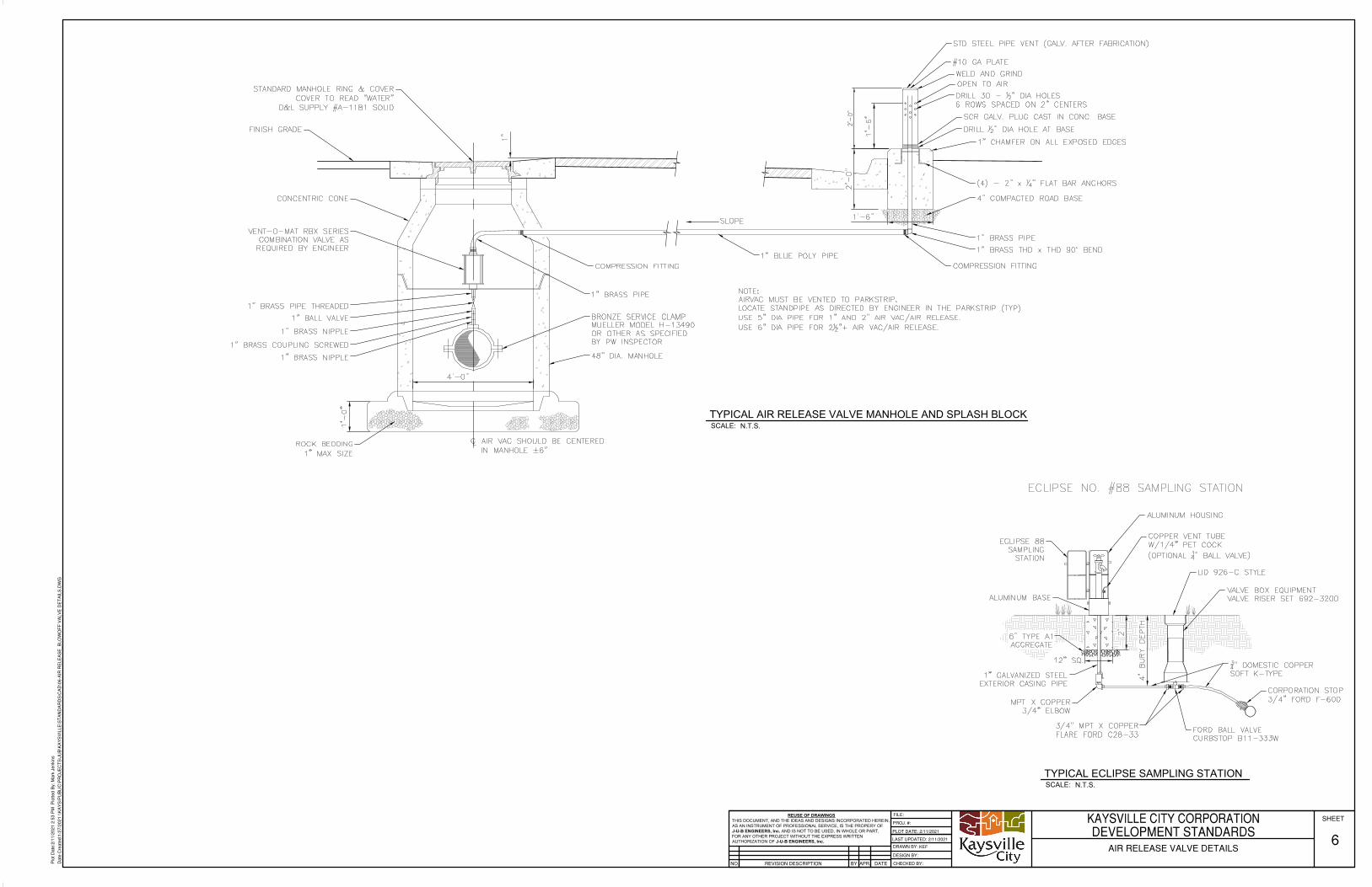
REUSE OF DRAWINGSTHIS DOCUMENT, AND THE IDEAS AND DESIGNS INCORPORATED HEREIN,AS AN INSTRUMENT OF PROFESSIONAL SERVICE, IS THE PROPERY OFJ-U-B ENGINEERS, Inc. AND IS NOT TO BE USED, IN WHOLE OR PART,FOR ANY OTHER PROJECT WITHOUT THE EXPRESS WRITTENAUTHORIZATION OF J-U-B ENGINEERS, Inc.
REVISION DESCRIPTIONNO.
PROJ. #:
DESIGN BY:
DRAWN BY:
CHECKED BY:APR. DATEBY
SHEETFILE:
LAST UPDATED: 2/11/2021
PLOT DATE: 2/11/2021
Plo
t Dat
e:2/
11/2
021
2:53
PM
Plo
tted
By:
Mar
k Je
nkin
s
Dat
e C
reat
ed:1
/27/
2021
\\K
AY
S\P
UB
LIC
\PR
OJE
CT
S\J
UB
\KA
YS
VIL
LE\S
TA
ND
AR
DS
\CA
D\0
6-A
IR R
ELE
AS
E_B
LOW
OF
F V
ALV
E D
ET
AIL
S.D
WG
KAYSVILLE CITY CORPORATIONDEVELOPMENT STANDARDS
AIR RELEASE VALVE DETAILS6
KEF
SCALE:TYPICAL AIR RELEASE VALVE MANHOLE AND SPLASH BLOCK
N.T.S.
SCALE:TYPICAL ECLIPSE SAMPLING STATION
N.T.S.
AutoCAD SHX Text
STD STEEL PIPE VENT (GALV. AFTER FABRICATION)
AutoCAD SHX Text
#10 GA PLATE
AutoCAD SHX Text
WELD AND GRIND
AutoCAD SHX Text
OPEN TO AIR
AutoCAD SHX Text
DRILL 30 - " DIA HOLES 12" DIA HOLES 6 ROWS SPACED ON 2" CENTERS
AutoCAD SHX Text
SCR GALV. PLUG CAST IN CONC. BASE
AutoCAD SHX Text
DRILL " DIA HOLE AT BASE12" DIA HOLE AT BASE
AutoCAD SHX Text
1" CHAMFER ON ALL EXPOSED EDGES
AutoCAD SHX Text
(4) - 2" x " FLAT BAR ANCHORS14" FLAT BAR ANCHORS
AutoCAD SHX Text
4" COMPACTED ROAD BASE
AutoCAD SHX Text
1" BRASS PIPE
AutoCAD SHX Text
1" BRASS THD x THD 90° BEND
AutoCAD SHX Text
COMPRESSION FITTING
AutoCAD SHX Text
1" BLUE POLY PIPE
AutoCAD SHX Text
ROCK BEDDING 1" MAX SIZE
AutoCAD SHX Text
BRONZE SERVICE CLAMP MUELLER MODEL H-13490 OR OTHER AS SPECIFIED BY PW INSPECTOR
AutoCAD SHX Text
1" BRASS PIPE
AutoCAD SHX Text
1" BRASS NIPPLE
AutoCAD SHX Text
1" BRASS COUPLING SCREWED
AutoCAD SHX Text
1" BRASS NIPPLE
AutoCAD SHX Text
1" BALL VALVE
AutoCAD SHX Text
1" BRASS PIPE THREADED
AutoCAD SHX Text
VENT-O-MAT RBX SERIES COMBINATION VALVE AS REQUIRED BY ENGINEER
AutoCAD SHX Text
CONCENTRIC CONE
AutoCAD SHX Text
FINISH GRADE
AutoCAD SHX Text
STANDARD MANHOLE RING & COVER COVER TO READ "WATER" D&L SUPPLY #A-1181 SOLID
AutoCAD SHX Text
NOTE: AIRVAC MUST BE VENTED TO PARKSTRIP. LOCATE STANDPIPE AS DIRECTED BY ENGINEER IN THE PARKSTRIP (TYP). USE 5" DIA PIPE FOR 1" AND 2" AIR VAC/AIR RELEASE. USE 6" DIA PIPE FOR 2 "+ AIR VAC/AIR RELEASE.12"+ AIR VAC/AIR RELEASE.
AutoCAD SHX Text
SLOPE
AutoCAD SHX Text
AIR VAC SHOULD BE CENTERED IN MANHOLE ±6"
AutoCAD SHX Text
AutoCAD SHX Text
48" DIA. MANHOLE
AutoCAD SHX Text
COMPRESSION FITTING
AutoCAD SHX Text
6" TYPE A1 AGGREGATE
AutoCAD SHX Text
ECLIPSE NO. #88 SAMPLING STATION
AutoCAD SHX Text
ECLIPSE 88 SAMPLING STATION
AutoCAD SHX Text
ALUMINUM HOUSING
AutoCAD SHX Text
ALUMINUM BASE
AutoCAD SHX Text
COPPER VENT TUBE W/1/4" PET COCK (OPTIONAL " BALL VALVE)14" BALL VALVE)
AutoCAD SHX Text
LID 926-C STYLE
AutoCAD SHX Text
1" GALVANIZED STEEL EXTERIOR CASING PIPE
AutoCAD SHX Text
MPT X COPPER 3/4" ELBOW
AutoCAD SHX Text
3/4" MPT X COPPER FLARE FORD C28-33
AutoCAD SHX Text
FORD BALL VALVE CURBSTOP B11-333W
AutoCAD SHX Text
CORPORATION STOP 3/4" FORD F-600
AutoCAD SHX Text
34" DOMESTIC COPPER SOFT K-TYPE
AutoCAD SHX Text
VALVE BOX EQUIPMENT VALVE RISER SET 692-3200

ƒ
3" BYPASS ELEVATION VIEW
MATERIAL LIST
ELEVATION VIEW
PLAN VIEW
REUSE OF DRAWINGSTHIS DOCUMENT, AND THE IDEAS AND DESIGNS INCORPORATED HEREIN,AS AN INSTRUMENT OF PROFESSIONAL SERVICE, IS THE PROPERY OFJ-U-B ENGINEERS, Inc. AND IS NOT TO BE USED, IN WHOLE OR PART,FOR ANY OTHER PROJECT WITHOUT THE EXPRESS WRITTENAUTHORIZATION OF J-U-B ENGINEERS, Inc.
REVISION DESCRIPTIONNO.
PROJ. #:
DESIGN BY:
DRAWN BY:
CHECKED BY:APR. DATEBY
SHEETFILE:
LAST UPDATED: 3/4/2021
PLOT DATE: 3/4/2021
Plo
t Dat
e:3/
4/20
21 3
:10
PM
Plo
tted
By:
Mar
k Je
nkin
s
Dat
e C
reat
ed:2
/11/
2021
\\K
AY
S\P
UB
LIC
\PR
OJE
CT
S\J
UB
\KA
YS
VIL
LE\S
TA
ND
AR
DS
\CA
D\0
7-P
RE
SS
UR
E R
ELI
EF
VA
LVE
.DW
G
KAYSVILLE CITY CORPORATIONDEVELOPMENT STANDARDSTYPICAL PRESSURE RELIEF VAVLE
7KEF
AutoCAD SHX Text
MARK
AutoCAD SHX Text
DESCRIPTION
AutoCAD SHX Text
SIZE
AutoCAD SHX Text
1
AutoCAD SHX Text
6
AutoCAD SHX Text
7
AutoCAD SHX Text
8
AutoCAD SHX Text
FL
AutoCAD SHX Text
GATE VALVE
AutoCAD SHX Text
SCR
AutoCAD SHX Text
QUANTITY
AutoCAD SHX Text
1
AutoCAD SHX Text
2
AutoCAD SHX Text
SCR
AutoCAD SHX Text
2
AutoCAD SHX Text
PIPE SUPPORT
AutoCAD SHX Text
4
AutoCAD SHX Text
FLG
AutoCAD SHX Text
FLxPE
AutoCAD SHX Text
2
AutoCAD SHX Text
FL
AutoCAD SHX Text
1
AutoCAD SHX Text
"
AutoCAD SHX Text
2
AutoCAD SHX Text
MJ/MJ
AutoCAD SHX Text
10
AutoCAD SHX Text
BOLTS, NUTS, GASKETS, FOLLOWERS
AutoCAD SHX Text
AS REQ'D.
AutoCAD SHX Text
PER PLANS
AutoCAD SHX Text
AS REQ'D.
AutoCAD SHX Text
11
AutoCAD SHX Text
SLEEVE
AutoCAD SHX Text
MJ/MJ
AutoCAD SHX Text
2
AutoCAD SHX Text
12
AutoCAD SHX Text
BALL VALVE; CONNECT TO 1/4" AIR HOSE
AutoCAD SHX Text
BALL VALVE
AutoCAD SHX Text
SCR
AutoCAD SHX Text
1"
AutoCAD SHX Text
1
AutoCAD SHX Text
1
AutoCAD SHX Text
1"
AutoCAD SHX Text
SCR
AutoCAD SHX Text
UNION
AutoCAD SHX Text
A
AutoCAD SHX Text
PI
AutoCAD SHX Text
8
AutoCAD SHX Text
1
AutoCAD SHX Text
1
AutoCAD SHX Text
6
AutoCAD SHX Text
8
AutoCAD SHX Text
19
AutoCAD SHX Text
17
AutoCAD SHX Text
15
AutoCAD SHX Text
7
AutoCAD SHX Text
14
AutoCAD SHX Text
7
AutoCAD SHX Text
14
AutoCAD SHX Text
12
AutoCAD SHX Text
11
AutoCAD SHX Text
3
AutoCAD SHX Text
AS REQ'D.
AutoCAD SHX Text
4
AutoCAD SHX Text
1
AutoCAD SHX Text
9
AutoCAD SHX Text
PI
AutoCAD SHX Text
JOINT
AutoCAD SHX Text
2
AutoCAD SHX Text
5
AutoCAD SHX Text
1
AutoCAD SHX Text
IN INCHES
AutoCAD SHX Text
2
AutoCAD SHX Text
26
AutoCAD SHX Text
15
AutoCAD SHX Text
18
AutoCAD SHX Text
7
AutoCAD SHX Text
7
AutoCAD SHX Text
2
AutoCAD SHX Text
3
AutoCAD SHX Text
4
AutoCAD SHX Text
4
AutoCAD SHX Text
1
AutoCAD SHX Text
10
AutoCAD SHX Text
1
AutoCAD SHX Text
6
AutoCAD SHX Text
5
AutoCAD SHX Text
FLOOR SUMP 12" x 3 1/2" DEEP
AutoCAD SHX Text
FLOW
AutoCAD SHX Text
FLOW
AutoCAD SHX Text
FLOW
AutoCAD SHX Text
DUCTILE IRON PIPE
AutoCAD SHX Text
PRESSURE REDUCING VALVE [CLA-VAL #90-01]
AutoCAD SHX Text
13
AutoCAD SHX Text
FL
AutoCAD SHX Text
1
AutoCAD SHX Text
REDUCING TEE
AutoCAD SHX Text
14
AutoCAD SHX Text
15
AutoCAD SHX Text
90^ ELBOW
AutoCAD SHX Text
DUCTILE IRON PIPE
AutoCAD SHX Text
FLxPE
AutoCAD SHX Text
FL
AutoCAD SHX Text
3"
AutoCAD SHX Text
3"
AutoCAD SHX Text
2
AutoCAD SHX Text
AS REQ'D.
AutoCAD SHX Text
16
AutoCAD SHX Text
FL
AutoCAD SHX Text
N/A
AutoCAD SHX Text
3"
AutoCAD SHX Text
1
AutoCAD SHX Text
17
AutoCAD SHX Text
PRESSURE REDUCING VALVE [CLA-VAL #90-01]
AutoCAD SHX Text
FL
AutoCAD SHX Text
2"
AutoCAD SHX Text
1
AutoCAD SHX Text
18
AutoCAD SHX Text
GATE VALVE
AutoCAD SHX Text
FLG
AutoCAD SHX Text
3"
AutoCAD SHX Text
3
AutoCAD SHX Text
19
AutoCAD SHX Text
SLEEVE
AutoCAD SHX Text
MJ/MJ
AutoCAD SHX Text
2"
AutoCAD SHX Text
1
AutoCAD SHX Text
20
AutoCAD SHX Text
21
AutoCAD SHX Text
1"
AutoCAD SHX Text
1"
AutoCAD SHX Text
1
AutoCAD SHX Text
1
AutoCAD SHX Text
BLOW-OFF (ALL BRASS MATERIAL)
AutoCAD SHX Text
21
AutoCAD SHX Text
20
AutoCAD SHX Text
22
AutoCAD SHX Text
8
AutoCAD SHX Text
13
AutoCAD SHX Text
14
AutoCAD SHX Text
14
AutoCAD SHX Text
24
AutoCAD SHX Text
22
AutoCAD SHX Text
RESTRAINING BOLT (TYP. 2 180^ OFFSET)
AutoCAD SHX Text
22
AutoCAD SHX Text
C MH
AutoCAD SHX Text
L
AutoCAD SHX Text
C MH
AutoCAD SHX Text
L
AutoCAD SHX Text
C
AutoCAD SHX Text
L
AutoCAD SHX Text
(MIN)
AutoCAD SHX Text
(MIN)
AutoCAD SHX Text
(MIN)
AutoCAD SHX Text
(MIN)
AutoCAD SHX Text
C PIPE
AutoCAD SHX Text
L
AutoCAD SHX Text
FLOW
AutoCAD SHX Text
ALL SMALL PIPE FITTINGS AT INSTRUMENTS AND
AutoCAD SHX Text
AIR-VAC, ETC. NEED TO BE BRASS OR BRONZE
AutoCAD SHX Text
ANCHOR FEMALE AIR HOSE QUICK CONNECT TO CEILING WITH ACCESS NEAR LID
AutoCAD SHX Text
-
AutoCAD SHX Text
DUCTILE IRON REDUCER
AutoCAD SHX Text
TYPICAL NOTE:
AutoCAD SHX Text
6" OR 8"
AutoCAD SHX Text
6" OR 8"
AutoCAD SHX Text
6" OR 8"
AutoCAD SHX Text
6" OR 8"
AutoCAD SHX Text
6" OR 8" X 3"
AutoCAD SHX Text
8,10, OR 12" X 6, OR 8"
AutoCAD SHX Text
6" OR 8" D.I.
AutoCAD SHX Text
6" OR 8" D.I.
AutoCAD SHX Text
23
AutoCAD SHX Text
24
AutoCAD SHX Text
25
AutoCAD SHX Text
REDUCING CROSS
AutoCAD SHX Text
3"
AutoCAD SHX Text
1
AutoCAD SHX Text
1
AutoCAD SHX Text
2
AutoCAD SHX Text
6" OR 8" X 3"
AutoCAD SHX Text
3" X 2"
AutoCAD SHX Text
25
AutoCAD SHX Text
25
AutoCAD SHX Text
23
AutoCAD SHX Text
DUCTILE IRON REDUCER
AutoCAD SHX Text
26
AutoCAD SHX Text
AS REQ'D
AutoCAD SHX Text
2"
AutoCAD SHX Text
DUCTILE IRON PIPE
AutoCAD SHX Text
26
AutoCAD SHX Text
18
AutoCAD SHX Text
18
AutoCAD SHX Text
25
AutoCAD SHX Text
25
AutoCAD SHX Text
CAST IRON "Y" STRAINER - MUELLER STEAM SPECIALTY #752
AutoCAD SHX Text
CAST IRON "Y" STRAINER - MUELLER STEAM SPECIALTY #752
AutoCAD SHX Text
PRESSURE RELIEF VALVE [CLA-VAL #50-01]
AutoCAD SHX Text
10
AutoCAD SHX Text
6,8,10, OR 12"
AutoCAD SHX Text
27
AutoCAD SHX Text
27
AutoCAD SHX Text
VALVE POSITION INDICATOR [CLA-VAL #X101]
AutoCAD SHX Text
2
AutoCAD SHX Text
FLOW
AutoCAD SHX Text
10
AutoCAD SHX Text
27
AutoCAD SHX Text
FIT A 2",6"OR 8" VALVE
AutoCAD SHX Text
28
AutoCAD SHX Text
28
AutoCAD SHX Text
28
AutoCAD SHX Text
28
AutoCAD SHX Text
28
AutoCAD SHX Text
4
AutoCAD SHX Text
6"OR 8"
AutoCAD SHX Text
MEGA LUG FOLLOWERS W/1/4" STEEL PLATES ON BOTH SIDES OF WALL
AutoCAD SHX Text
WITH BALL VALVE & FAUCET/HOSE BIB TO FLUSH OUT SYSTEM
AutoCAD SHX Text
WITH BALL VALVE & FAUCET/HOSE BIB TO FLUSH OUT SYSTEM
AutoCAD SHX Text
COMBINATION AIR VALVE, VENT-O-MAT SERIES RBX 2521 OR EQUAL
AutoCAD SHX Text
GROUT OPENING W/ NON-SHRINK GROUT FLUSH BOTH SIDES (TYP)
AutoCAD SHX Text
1" BLOW-OFF VENTED OUTSIDE (ALL BRASS MAT'L.)
AutoCAD SHX Text
1" VENT-O-MAT SERIES RBX 2521 OR EQUAL
AutoCAD SHX Text
8, 10, OR 12" PVC (SEE CALLOUTS ON PLAN SHEET)
AutoCAD SHX Text
STANDARD RUNG LADDER TO BE PROVIDED WITH PRE-CAST VAULT
AutoCAD SHX Text
30" SOLID MANHOLE RING & VENTED COVER. COVER TO SAY "WATER"
AutoCAD SHX Text
ACCESS MANHOLE 36" SOLID MANHOLE RING & VENTED COVER. COVER TO SAY "WATER"
AutoCAD SHX Text
CONC. COLLAR PER KAYSVILLE CITY STANDARDS (TYP. 2 PLCS)
AutoCAD SHX Text
BITUMINOUS SURFACE COURSE NOTE: THICKNESS IS TO BE 4" OR TO MATCH EXISTING THICKNESS, WHICHEVER IS GREATER.
AutoCAD SHX Text
CONCRETE PRECAST VAULT W/ FLAT LID. CONTRACTOR TO SUBMIT SHOP DRAWINGS OF VAULT AND REBAR SCHEDULE TO ENGINEER FOR REVIEW.
AutoCAD SHX Text
8, 10, OR 12" PVC (SEE CALLOUTS ON PLAN SHEET)
AutoCAD SHX Text
12" THK. 1" WASHED GRAVEL FOUNDATION MATERIAL PER SPEC. (SEE DIVISION 2)
AutoCAD SHX Text
8, 10, OR 12" PVC (SEE CALLOUTS ON PLAN SHEET)
AutoCAD SHX Text
8, 10, OR 12" PVC (SEE CALLOUTS ON PLAN SHEET)
AutoCAD SHX Text
STANDARD RUNG LADDER TO BE PROVIDED WITH PRE-CAST VAULT
AutoCAD SHX Text
FLOOR SUMP: 12" X 312" DEEP
AutoCAD SHX Text
SEE DETAIL SHEET 13
AutoCAD SHX Text
(TYP)
AutoCAD SHX Text
(4) 1" PVC CONDUITS. EXTEND AND CAP
AutoCAD SHX Text
3" D.I.
AutoCAD SHX Text
5

MATERIAL LIST
3" PRESSURE RELIEF ELEVATION VIEW PLAN VIEW
REUSE OF DRAWINGSTHIS DOCUMENT, AND THE IDEAS AND DESIGNS INCORPORATED HEREIN,AS AN INSTRUMENT OF PROFESSIONAL SERVICE, IS THE PROPERY OFJ-U-B ENGINEERS, Inc. AND IS NOT TO BE USED, IN WHOLE OR PART,FOR ANY OTHER PROJECT WITHOUT THE EXPRESS WRITTENAUTHORIZATION OF J-U-B ENGINEERS, Inc.
REVISION DESCRIPTIONNO.
PROJ. #:
DESIGN BY:
DRAWN BY:
CHECKED BY:APR. DATEBY
SHEETFILE:
LAST UPDATED: 2/11/2021
PLOT DATE: 2/11/2021
Plo
t Dat
e:2/
11/2
021
3:37
PM
Plo
tted
By:
Mar
k Je
nkin
s
Dat
e C
reat
ed:2
/11/
2021
\\K
AY
S\P
UB
LIC
\PR
OJE
CT
S\J
UB
\KA
YS
VIL
LE\S
TA
ND
AR
DS
\CA
D\0
8-P
RE
SS
UR
E R
ELI
EF
VA
LVE
DE
TA
ILS
.DW
G
KAYSVILLE CITY CORPORATIONDEVELOPMENT STANDARDSTYPICAL PRESSURE RELIEF VALVE
DETAILS
8KEF
AutoCAD SHX Text
MARK
AutoCAD SHX Text
DESCRIPTION
AutoCAD SHX Text
SIZE
AutoCAD SHX Text
1
AutoCAD SHX Text
QUANTITY
AutoCAD SHX Text
1
AutoCAD SHX Text
FLxPE
AutoCAD SHX Text
BOLTS, NUTS, GASKETS, FOLLOWERS
AutoCAD SHX Text
AS REQ'D.
AutoCAD SHX Text
PER PLANS
AutoCAD SHX Text
AS REQ'D.
AutoCAD SHX Text
AS REQ'D.
AutoCAD SHX Text
4
AutoCAD SHX Text
JOINT
AutoCAD SHX Text
2
AutoCAD SHX Text
1
AutoCAD SHX Text
IN INCHES
AutoCAD SHX Text
DUCTILE IRON PIPE
AutoCAD SHX Text
3"
AutoCAD SHX Text
90° ELBOW
AutoCAD SHX Text
FL
AutoCAD SHX Text
3"
AutoCAD SHX Text
3
AutoCAD SHX Text
FL
AutoCAD SHX Text
3"
AutoCAD SHX Text
1
AutoCAD SHX Text
SCREENED DOWNWARD (180°) ELBOW (#14 MESH, NON-CORRODIBLE)
AutoCAD SHX Text
2
AutoCAD SHX Text
1
AutoCAD SHX Text
3
AutoCAD SHX Text
EXISTING OR FUTURE CURB & GUTTER
AutoCAD SHX Text
SCREENED DOWNWARD ELBOW (#14 MESH, NON-CORRODIBLE)
AutoCAD SHX Text
TAP " HOLE IN BOTTOM OF 14" HOLE IN BOTTOM OF PIPE & DRAIN TO 1'X2' GRAVEL SUMP
AutoCAD SHX Text
(4) 1" PVC CONDUITS. EXTEND AND CAP
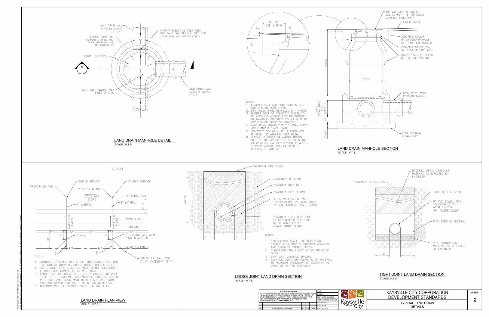
A
SCALE:LOOSE-JOINT LAND DRAIN SECTION
N.T.S.
SCALE:LAND DRAIN MANHOLE DETAIL
N.T.S.
SCALE:LAND DRAIN MANHOLE SECTION
N.T.S.
SCALE:TIGHT-JOINT LAND DRAIN SECTION
N.T.S.
SCALE:LAND DRAIN PLAN VIEW
N.T.S.
REUSE OF DRAWINGSTHIS DOCUMENT, AND THE IDEAS AND DESIGNS INCORPORATED HEREIN,AS AN INSTRUMENT OF PROFESSIONAL SERVICE, IS THE PROPERY OFJ-U-B ENGINEERS, Inc. AND IS NOT TO BE USED, IN WHOLE OR PART,FOR ANY OTHER PROJECT WITHOUT THE EXPRESS WRITTENAUTHORIZATION OF J-U-B ENGINEERS, Inc.
REVISION DESCRIPTIONNO.
PROJ. #:
DESIGN BY:
DRAWN BY:
CHECKED BY:APR. DATEBY
SHEETFILE:
LAST UPDATED: 2/11/2021
PLOT DATE: 2/11/2021
Plo
t Dat
e:2/
11/2
021
3:11
PM
Plo
tted
By:
Mar
k Je
nkin
s
Dat
e C
reat
ed:2
/11/
2021
\\K
AY
S\P
UB
LIC
\PR
OJE
CT
S\J
UB
\KA
YS
VIL
LE\S
TA
ND
AR
DS
\CA
D\0
9-S
UB
SU
RF
AC
E D
RA
IN D
ET
AIL
S.D
WG
KAYSVILLE CITY CORPORATIONDEVELOPMENT STANDARDS
TYPICAL LAND DRAINDETAILS
9KEF
AutoCAD SHX Text
LAND DRAIN MAIN (VARIOUS SIZES) 8" TYP.
AutoCAD SHX Text
OUTSIDE SHAPE OF CONCRETE BASE AND ROCK BEDDING MAY BE IRREGULAR
AutoCAD SHX Text
SLOPE 8% (TYP.)
AutoCAD SHX Text
CONTOUR FLOWLINE AND SIDES OF M.H.
AutoCAD SHX Text
O-RING GASKET AS SEEP RING USE SAME DIAMETER AS USED FOR JOINT SEAL OR LARGER (TYP.)
AutoCAD SHX Text
LAND DRAIN MAIN (VARIOUS SIZES) 8" TYP.
AutoCAD SHX Text
CONCRETE COLLAR 18" AROUND MANHOLE 12" THICK. SEE NOTE 5
AutoCAD SHX Text
CONCRETE GRADE RING AS REQUIRED (10" MAX)
AutoCAD SHX Text
JOINTS SHALL BE FILLED WITH BITUMEN MASTIC
AutoCAD SHX Text
LAND DRAIN MAIN (VARIOUS SIZES)
AutoCAD SHX Text
ROCK BEDDING 1" MAX SIZE
AutoCAD SHX Text
30" M.H. RING & COVER D&L SUPPLY 1181 OR EQUAL STAMPED "LAND DRAIN"
AutoCAD SHX Text
FINISH GRADE
AutoCAD SHX Text
NOTES: 1. MANHOLE WALL AND CONE SECTION SHALL MANHOLE WALL AND CONE SECTION SHALL CONFORM TO ASTM C 478. 2. LIFT HOLES SHALL BE FILLED WITH GROUT. LIFT HOLES SHALL BE FILLED WITH GROUT. 3. RUBBER BOOT OR CONCRETE COLLAR TO RUBBER BOOT OR CONCRETE COLLAR TO BE INSTALLED AROUND PIPE ON OUTSIDE OF MANHOLE (CONCRETE COLLAR MUST BE GROUTED ON INSIDE OF MANHOLE). 4. LAND DRAIN MANHOLE TO BE NON-VENTED LAND DRAIN MANHOLE TO BE NON-VENTED AND STAMPED "LAND DRAIN". 5. CONCRETE COLLAR - 12" IF FIBER MESH CONCRETE COLLAR - 12" IF FIBER MESH IS USED, 18" WITH NO FIBER MESH. 6. INSTALL 12 GAUGE OR LARGER TRACER INSTALL 12 GAUGE OR LARGER TRACER WIRE UP TO MANHOLE LID. NOTCH IN TOP OF CONE OR MANHOLE SECTION " WIDE x 14" WIDE x 1" DEEP SAWCUT FROM EXTERIOR TO INTERIOR OF MANHOLE
AutoCAD SHX Text
12"-18"
AutoCAD SHX Text
12"-18"
AutoCAD SHX Text
PREFORMED WYE
AutoCAD SHX Text
PREFORMED WYE
AutoCAD SHX Text
SINGLE SERVICE
AutoCAD SHX Text
ROAD
AutoCAD SHX Text
DOUBLE SERVICE
AutoCAD SHX Text
4" LATERAL
AutoCAD SHX Text
PARK STRIP
AutoCAD SHX Text
SIDEWALK
AutoCAD SHX Text
8" LAND DRAIN
AutoCAD SHX Text
4" LATERAL
AutoCAD SHX Text
AutoCAD SHX Text
AutoCAD SHX Text
EXTEND LATERAL PAST UTILITY EASEMENT (TYP.)
AutoCAD SHX Text
4" DOUBLE WYE WITH PLUG IN CENTER
AutoCAD SHX Text
UTILITY EASEMENT
AutoCAD SHX Text
4" WYE
AutoCAD SHX Text
NOTES: 1. CONTRACTOR SHALL USE SINGLE OR DOUBLE PULL BOX CONTRACTOR SHALL USE SINGLE OR DOUBLE PULL BOX TO PROTECT WORKERS AND STABILIZE TRENCH SIDES. 2. ALL CONNECTIONS SHALL BE MADE USING PREFORMED ALL CONNECTIONS SHALL BE MADE USING PREFORMED FITTINGS CONFORMING TO ASTM D-3034. 3. LAND DRAIN LATERALS TO BE GREEN COLOR PVC WITH LAND DRAIN LATERALS TO BE GREEN COLOR PVC WITH TAPE ON THE LATERALS AND WRAPPED AROUND END OF PIPE AND LAND DRAIN MAIN TO DIFFERENTIATE FROM SANITARY SEWER LATERALS. MARK END WITH A 2x4. 4. MAXIMUM MANHOLE SPACING SHALL BE 500 FEET.MAXIMUM MANHOLE SPACING SHALL BE 500 FEET.
AutoCAD SHX Text
0.25% MIN. SLOPE
AutoCAD SHX Text
0.25% MIN. SLOPE
AutoCAD SHX Text
0.25% MIN. SLOPE
AutoCAD SHX Text
BACKFILL USING GRANULAR MATERIAL AS DIRECTED BY ENGINEER
AutoCAD SHX Text
8" PVC SEWER PIPE CONFORMING TO ASTM D-3034 MIN. SLOPE 0.25%
AutoCAD SHX Text
PIPE BEDDING MATERIAL
AutoCAD SHX Text
PIPE FOUNDATION MATERIAL AS DIRECTED BY ENGINEER
AutoCAD SHX Text
PAVEMENT STRUCTURE
AutoCAD SHX Text
UNDISTURBED EARTH
AutoCAD SHX Text
UNDISTURBED EARTH
AutoCAD SHX Text
CONCRETE PIPE BELL
AutoCAD SHX Text
CONCRETE PIPE SPIGOT
AutoCAD SHX Text
FILTER MATERIAL TO MEET SPECIFICATIONS AS DETERMINED BY GEOTECHNICAL INVESTIGATION
AutoCAD SHX Text
CONCRETE LUG-JOINT PIPE OR PERFORATED PVC PIPE TO BE WRAPPED WITH MIRAFI 140NC FABRIC
AutoCAD SHX Text
NOTES: 1. CONTRACTOR SHALL USE SINGLE OR CONTRACTOR SHALL USE SINGLE OR DOUBLE PULL BOX TO PROTECT WORKERS AND STABILIZE TRENCH SIDES. 2. DEWATERING SHALL NOT ALLOW PIPING OF DEWATERING SHALL NOT ALLOW PIPING OF FINES. 3. 500' MAX. MANHOLE SPACING 500' MAX. MANHOLE SPACING 4. BACKFILL USING GRANULAR FILTER MATERIAL BACKFILL USING GRANULAR FILTER MATERIAL TO MAXIMUM GROUNDWATER ELEVATION AS DIRECTED BY THE ENGINEER.
AutoCAD SHX Text
PAVEMENT STRUCTURE

REUSE OF DRAWINGSTHIS DOCUMENT, AND THE IDEAS AND DESIGNS INCORPORATED HEREIN,AS AN INSTRUMENT OF PROFESSIONAL SERVICE, IS THE PROPERY OFJ-U-B ENGINEERS, Inc. AND IS NOT TO BE USED, IN WHOLE OR PART,FOR ANY OTHER PROJECT WITHOUT THE EXPRESS WRITTENAUTHORIZATION OF J-U-B ENGINEERS, Inc.
REVISION DESCRIPTIONNO.
PROJ. #:
DESIGN BY:
DRAWN BY:
CHECKED BY:APR. DATEBY
SHEETFILE:
LAST UPDATED: 1/20/2021
PLOT DATE: 2/11/2021
Plo
t Dat
e:2/
11/2
021
3:12
PM
Plo
tted
By:
Mar
k Je
nkin
s
Dat
e C
reat
ed:1
/20/
2021
\\K
AY
S\P
UB
LIC
\PR
OJE
CT
S\J
UB
\KA
YS
VIL
LE\S
TA
ND
AR
DS
\CA
D\1
0-S
D C
OM
BO
BO
X.D
WG
KAYSVILLE CITY CORPORATIONDEVELOPMENT STANDARDS
STORM DRAIN COMBINATION INLET/CLEANOUT BOXDETAILS
10KEF
SCALE:COMBINATION INLET/CLEANOUT
N.T.S.
SCALE:TOP SLAB
N.T.S.
AutoCAD SHX Text
#5 @ 8" O.C.
AutoCAD SHX Text
OPENING
AutoCAD SHX Text
#5 @ 9"
AutoCAD SHX Text
CONCRETE FILL
AutoCAD SHX Text
#4 @ 12" O.C.
AutoCAD SHX Text
PRECAST RISER AS REQ'D
AutoCAD SHX Text
30" DIA. OPENING
AutoCAD SHX Text
#5 @ 9"
AutoCAD SHX Text
STANDARD MANHOLE RING & COVER COVER TO READ "STORM DRAIN" D&L SUPPLY #A-1181 SOLID
AutoCAD SHX Text
CONCRETE COLLAR 18" AROUND MANHOLE 12" THICK
AutoCAD SHX Text
D&L SUPPLY #1-3517 SINGLE UNIT CURB INLET BOX W/TYPE "L" GRATE
AutoCAD SHX Text
#4 @ 12" O.C. EACH WAY (TOP) #5 @ 9" O.C. EACH WAY (BTM)
AutoCAD SHX Text
(2) #6 BARS (BTM MAT - TYP)
AutoCAD SHX Text
#5 DIAG. BAR (TOP & BTM - TYP)
AutoCAD SHX Text
(2) #6 BARS (BTM MAT - TYP)
AutoCAD SHX Text
#5 ROOF DOWEL @ 9" O.C.
AutoCAD SHX Text
SEE NOTE BELOW
AutoCAD SHX Text
#4 @ 10" HORZ. (TYP)
AutoCAD SHX Text
#5 @ 9" VERT (TYP)
AutoCAD SHX Text
#5 @ 9" T&B EACH WAY
AutoCAD SHX Text
ADD #5 DIAGONAL BARS @ 4 SIDES OF PIPE LENGTH =PIPE SIZE+3'-0"
AutoCAD SHX Text
#4 @ 10" HORZ. (TYP)
AutoCAD SHX Text
#5 @ 9" VERT (TYP)
AutoCAD SHX Text
SEE NOTE BELOW
AutoCAD SHX Text
#5 @ 9" T&B EACH WAY
AutoCAD SHX Text
ROCK BEDDING 1" MAX. SIZE (TYP)
AutoCAD SHX Text
NOTE: USE 6" THICK WALLS FOR WALL HEIGHT UP TO 5'-0". FOR WALL HEIGHT GREATER THAN 5'-0", USE 8" THICK WALLS.
AutoCAD SHX Text
GENERAL NOTES: 1. ALL STRUCTURAL CONCRETE SHALL DEVELOP A MINIMUM COMPRESSIVE STRENGTH OF 4,000 PSI IN 28 DAYS. 2. REINFORCEMENT STEEL SHALL BE DEFORMED BARS CONFORMING IN QUALITY TO THE REQUIREMENTS OF ASTM DESIGNATION A-615, GRADE 60, INCLUDING SUPPLEMENTARY REQUIREMENTS (S1). 3. ALL DETAILING, FABRICATION AND PLACING OF REINFORCING BARS SHALL BE IN ACCORDANCE WITH THE "MANUAL OF STANDARD PRACTICE FOR DETAILING REINFORCED CONCRETE STRUCTURES" ACI-315, LATEST EDITION. 4. TOLERANCES IN PLACING REINFORCEMENT SHALL BE: ± INCH FOR MEMBERS WITH D < 8 INCHES 38 INCH FOR MEMBERS WITH D < 8 INCHES ± INCH FOR MEMBERS WITH D >= 8 INCHES 12 INCH FOR MEMBERS WITH D >= 8 INCHES 5. DOWELS, PIPES, WATERSTOPS AND OTHER INSTALLED MATERIALS AND ACCESSORIES SHALL BE HELD SECURELY IN POSITION WHILE CONCRETE IS BEING PLACED. 6. UNLESS OTHERWISE SHOWN, ASIDE FROM NORMAL ACCESSORIES USED TO HOLD REINFORCING BARS FIRMLY IN POSITION, THE FOLLOWING SHALL BE ADDED: A) IN SLABS #5 RISER BARS AT 36 INCHES O.C. MAXIMUM TO SUPPORT TOP REINFORCING BARS. B) IN WALLS WITH 2 CURTAINS #3 U OR Z SHAPE SPACES AT 6 FEET O.C. EACH WAY. 7. METAL CLIPS OR SUPPORTS SHALL NOT BE PLACED IN CONTACT WITH THE FORMS OR THE SUBGRADE. CONCRETE BLOCKS (OR DOBBIES) SUPPORTING BARS ON SUBGRADE SHALL BE IN SUFFICIENT NUMBERS TO SUPPORT THE BARS WITHOUT SETTLEMENT, BUT IN NO CASE SHALL SUCH SUPPORT BE CONTINUOUS. 8. DOWELS SHALL BE WIRED OR OTHERWISE HELD IN POSITION. THEY SHALL NOT BE SHOVED INTO FRESHLY PLACED CONCRETE. 9. REINFORCED BARS AND ACCESSORIES SHALL NOT BE IN CONTACT WITH ANY PIPE, PIPE FLANGE OR METAL PARTS EMBEDDED IN CONCRETE. A MINIMUM OF 2 INCHES CLEARANCE SHALL BE PROVIDED AT ALL TIMES. 10. STRUCTURES SHALL BE BACKFILLED WITH GRANULAR SOIL. 11. ALL CONSTRUCTION JOINTS SHALL BE ROUGHED AND CLEANED AND FREE OF LAITANCE. 12. STRUCTURES HAVE BEEN DESIGNED FOR THE FOLLOWING; IF CONDITIONS ARE EXCEEDED THE ENGINEER SHALL BE NOTIFIED. A) AASHTO HS-20 TRUCK LOAD B) 1'-6" MAX. SOIL ABOVE THE ROOF OF THE STRUCTURE C) GROUND WATER TO TOP OF STRUCTURE D) "AT-REST" LATERAL SOIL PRESSURE OF 60 PCF FOR DRY SOIL CONDITIONS AND 92.4 PCF WHEN GROUND WATER IS PRESENT. 13. A DOUBLE COMBINATION INLET/CLEANOUT BOX SHALL BE THE WIDTH OF THE DOUBLE CATCH BASIN, WITH ONE MANHOLE, RING & COVER. ALL OTHER APPLICABLE DETAILS ON THIS SHEET SHALL APPLY.
AutoCAD SHX Text
#5 ROOF DOWEL @ 9" O.C.

C
B
3
A
C
SCALE:1 PLAN AT DOUBLE CATCH BASIN N.T.S.
SCALE:A DOUBLE CATCH BASIN SECTION N.T.S.
SCALE:4 OPTIONAL FOOTING DETAIL AT WALL-PIPE CONNECTION N.T.S.
REUSE OF DRAWINGSTHIS DOCUMENT, AND THE IDEAS AND DESIGNS INCORPORATED HEREIN,AS AN INSTRUMENT OF PROFESSIONAL SERVICE, IS THE PROPERY OFJ-U-B ENGINEERS, Inc. AND IS NOT TO BE USED, IN WHOLE OR PART,FOR ANY OTHER PROJECT WITHOUT THE EXPRESS WRITTENAUTHORIZATION OF J-U-B ENGINEERS, Inc.
REVISION DESCRIPTIONNO.
PROJ. #:
DESIGN BY:
DRAWN BY:
CHECKED BY:APR. DATEBY
SHEETFILE:
LAST UPDATED: 1/20/2021
PLOT DATE: 2/11/2021
Plo
t Dat
e:2/
11/2
021
3:15
PM
Plo
tted
By:
Mar
k Je
nkin
s
Dat
e C
reat
ed:1
/20/
2021
\\K
AY
S\P
UB
LIC
\PR
OJE
CT
S\J
UB
\KA
YS
VIL
LE\S
TA
ND
AR
DS
\CA
D\1
1-S
TA
ND
AR
D C
AT
CH
BA
SIN
S.D
WG
KAYSVILLE CITY CORPORATIONDEVELOPMENT STANDARDS
STANDARD CATCH BASINDETAILS
11KEF
SCALE:C DOUBLE CATCH BASIN SECTION N.T.S.
SCALE:2 PLAN AT SINGLE CATCH BASIN N.T.S.
SCALE:B SINGLE CATCH BASIN SECTION N.T.S.
SCALE:3 CATCH BASIN DETAIL N.T.S.
SCALE:5 HORIZONTAL REINF. @ WALL INTERSECTION N.T.S.
AutoCAD SHX Text
6" CURB
AutoCAD SHX Text
D&L SUPPLY I-3517 SINGLE UNIT CURB INLET BOX WITH TYPE "L" GRATE
AutoCAD SHX Text
OPTIONAL CONSTRUCTION JOINT
AutoCAD SHX Text
#5 BAR @ 9" O.C.
AutoCAD SHX Text
#5 BAR @ 9" O.C.
AutoCAD SHX Text
CONCRETE FILL
AutoCAD SHX Text
ADD #5 DIAGONAL BARS @ 4 SIDES OF PIPE LENGTH = PIPE SIZE + 3'-0"
AutoCAD SHX Text
42" DIA MAX
AutoCAD SHX Text
(4) #4 X
AutoCAD SHX Text
OPTIONAL CONSTRUCTION JOINT ROUGHEN SURFACE IF C.J. IS USED
AutoCAD SHX Text
#4 BAR @ 12" O.C.
AutoCAD SHX Text
#4 BAR @ 9" O.C.
AutoCAD SHX Text
#5 BAR @ 9" O.C.
AutoCAD SHX Text
#5 BAR @ 9" O.C.
AutoCAD SHX Text
#5 BAR @ 9" O.C.
AutoCAD SHX Text
VARIABLE UP TO 3" MAXIMUM
AutoCAD SHX Text
TOP OF CHANNEL TO BE IN LINE WITH TOP AND FACE OF CURB
AutoCAD SHX Text
COMPACTION @ 95% IF IMPORTED MATERIAL IS USED
AutoCAD SHX Text
D&L SUPPLY I-3517 SINGLE UNIT CURB INLET BOX WITH TYPE "L" GRATE
AutoCAD SHX Text
6" CURB
AutoCAD SHX Text
MAXIMUM PIPE SIZE 24" DIA.
AutoCAD SHX Text
SEE SECTION A FOR REINFORCING
AutoCAD SHX Text
CONTROL JOINT
AutoCAD SHX Text
D&L SUPPLY I-3517 SINGLE UNIT CURB INLET BOX WITH TYPE "L" GRATE
AutoCAD SHX Text
GRATE TO MATCH SLOPE OF GUTTER
AutoCAD SHX Text
OPTIONAL CONSTRUCTION JOINT ROUGHEN SURFACE IF CONSTRUCTION JOINT IS USED
AutoCAD SHX Text
1:1
AutoCAD SHX Text
TYPICAL BOTTOM SLAB REINFORCEMENT
AutoCAD SHX Text
TYPICAL TOP SLAB REINFORCEMENT
AutoCAD SHX Text
Z
AutoCAD SHX Text
X
AutoCAD SHX Text
BAR SIZE
AutoCAD SHX Text
2'-2"
AutoCAD SHX Text
10"
AutoCAD SHX Text
#5
AutoCAD SHX Text
1'-8"
AutoCAD SHX Text
8"
AutoCAD SHX Text
#4
AutoCAD SHX Text
GENERAL NOTES: 1. ALL STRUCTURAL CONCRETE SHALL DEVELOP A MINIMUM ALL STRUCTURAL CONCRETE SHALL DEVELOP A MINIMUM COMPRESSIVE STRENGTH OF 4,000 PSI IN 28 DAYS 2. REINFORCEMENT STEEL SHALL BE DEFORMED BARS REINFORCEMENT STEEL SHALL BE DEFORMED BARS CONFORMING IN QUALITY TO THE REQUIREMENTS OF ASTM DESIGNATION A-615, GRADE 60, INCLUDING SUPPLEMENTARY REQUIREMENTS (S1). 3. ALL DETAILING, FABRICATION AND PLACING OF ALL DETAILING, FABRICATION AND PLACING OF REINFORCING BARS SHALL BE IN ACCORDANCE WITH THE "MANUAL OF STANDARD PRACTICE FOR DETAILING REINFORCED CONCRETE STRUCTURES" ACI-315, LATEST EDITION. 4. TOLERANCES IN PLACING REINFORCEMENT SHALL BE TOLERANCES IN PLACING REINFORCEMENT SHALL BE 4.1. 3/8 INCH FOR MEMBERS WITH D < 8 INCHES ±3/8 INCH FOR MEMBERS WITH D < 8 INCHES4.2. 1/2 INCH FOR MEMBERS WITH D >= 8 INCHES ±1/2 INCH FOR MEMBERS WITH D >= 8 INCHES5. DOWELS, PIPES, WATERSTOPS AND OTHER INSTALLED DOWELS, PIPES, WATERSTOPS AND OTHER INSTALLED MATERIALS AND ACCESSORIES SHALL BE HELD SECURELY IN POSITION WHILE CONCRETE IS BEING PLACED. 6. UNLESS OTHERWISE SHOWN, ASIDE FROM NORMAL UNLESS OTHERWISE SHOWN, ASIDE FROM NORMAL ACCESSORIES USED TO HOLD REINFORCING BARS FIRMLY IN POSITION. THE FOLLOWING SHALL BE ADDED 6.1. IN SLABS #5 BARS AT 36 INCHES O.C. MAXIMUM TO IN SLABS #5 BARS AT 36 INCHES O.C. MAXIMUM TO SUPPORT TOP REINFORCING BARS. 6.2. IN WALLS WITH 2 CURTAINS #3 U OR Z SHAPE IN WALLS WITH 2 CURTAINS #3 U OR Z SHAPE SPACES AT 6 FEET O.C. EACH WAY. 7. METAL CLIPS OR SUPPORTS SHALL NOT BE PLACED IN METAL CLIPS OR SUPPORTS SHALL NOT BE PLACED IN CONTACT WITH THE FORMS OR THE SUBGRADE. CONCRETE BLOCKS (OR DOBBIES) SUPPORTING BARS ON SUBGRADE SHALL BE IN SUFFICIENT NUMBERS TO SUPPORT THE BARS WITHOUT SETTLEMENT, BUT IN NO CASE SHALL SUCH SUPPORT BE CONTINUOUS. 8. DOWELS SHALL BE WIRED OR OTHERWISE HELD IN DOWELS SHALL BE WIRED OR OTHERWISE HELD IN POSITION. THEY SHALL NOT BE SHOVED INTO FRESHLY PLACED CONCRETE. 9. REINFORCED BARS AND ACCESSORIES SHALL NOT BE IN REINFORCED BARS AND ACCESSORIES SHALL NOT BE IN CONTACT WITH ANY PIPE, PIPE FLANGE OR METAL PARTS EMBEDDED CONCRETE. A MINIMUM OF 2 INCHES CLEARANCE SHALL BE PROVIDED AT ALL TIMES. 10. STRUCTURES SHALL BE BACKFILLED WITH GRANULAR SOIL. STRUCTURES SHALL BE BACKFILLED WITH GRANULAR SOIL. 11. ALL CONSTRUCTION JOINTS SHALL BE ROUGHED, CLEANED ALL CONSTRUCTION JOINTS SHALL BE ROUGHED, CLEANED AND FREE OF LAITANCE. 12. STRUCTURES HAVE BEEN DESIGNED FOR THE FOLLOWING: STRUCTURES HAVE BEEN DESIGNED FOR THE FOLLOWING: (IF CONDITIONS ARE EXCEEDED THE ENGINEER SHALL BE NOTIFIED) 12.1. AASHTO HS-20 TRUCK LOAD AASHTO HS-20 TRUCK LOAD 12.2. 1'-6" MAXIMUM SOIL ABOVE THE ROOF OF THE 1'-6" MAXIMUM SOIL ABOVE THE ROOF OF THE STRUCTURE 12.3. GROUND WATER TO TOP OF STRUCTURE GROUND WATER TO TOP OF STRUCTURE 12.4. "AT-REST" LATERAL SOIL PRESSURE OF 60 PCF FOR "AT-REST" LATERAL SOIL PRESSURE OF 60 PCF FOR DRY SOIL CONDITIONS AND 92.4 PCF WHEN GROUND WATER IS PRESENT
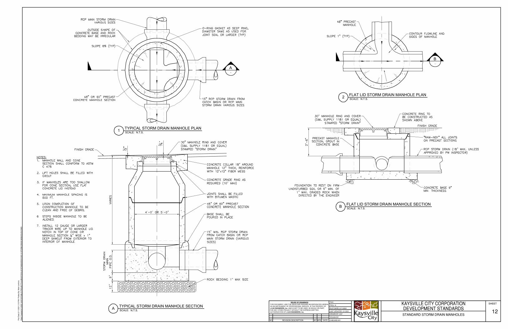
SCALE:B FLAT LID STORM DRAIN MANHOLE SECTION N.T.S.
SCALE:2 FLAT LID STORM DRAIN MANHOLE PLAN N.T.S.
SCALE:A TYPICAL STORM DRAIN MANHOLE SECTION N.T.S.
SCALE:1 TYPICAL STORM DRAIN MANHOLE PLAN N.T.S.
-B
-A
REUSE OF DRAWINGSTHIS DOCUMENT, AND THE IDEAS AND DESIGNS INCORPORATED HEREIN,AS AN INSTRUMENT OF PROFESSIONAL SERVICE, IS THE PROPERY OFJ-U-B ENGINEERS, Inc. AND IS NOT TO BE USED, IN WHOLE OR PART,FOR ANY OTHER PROJECT WITHOUT THE EXPRESS WRITTENAUTHORIZATION OF J-U-B ENGINEERS, Inc.
REVISION DESCRIPTIONNO.
PROJ. #:
DESIGN BY:
DRAWN BY:
CHECKED BY:APR. DATEBY
SHEETFILE:
LAST UPDATED: 2/1/2021
PLOT DATE: 2/11/2021
Plo
t Dat
e:2/
11/2
021
3:15
PM
Plo
tted
By:
Mar
k Je
nkin
s
Dat
e C
reat
ed:4
/1/2
020
\\KA
YS
\PU
BLI
C\P
RO
JEC
TS
\JU
B\K
AY
SV
ILLE
\ST
AN
DA
RD
S\C
AD
\12-
ST
OR
M D
RA
IN M
AN
HO
LES
.DW
G
KAYSVILLE CITY CORPORATIONDEVELOPMENT STANDARDSSTANDARD STORM DRAIN MANHOLES
12KEF
AutoCAD SHX Text
NOTES: 1. MANHOLE WALL AND CONE MANHOLE WALL AND CONE SECTION SHALL CONFORM TO ASTM C 478 2. LIFT HOLES SHALL BE FILLED WITH LIFT HOLES SHALL BE FILLED WITH GROUT 3. IF MANHOLES ARE TOO SHALLOW IF MANHOLES ARE TOO SHALLOW FOR CONE SECTION, USE FLAT CONCRETE LID INSTEAD 4. MAXIMUM MANHOLE SPACING IS MAXIMUM MANHOLE SPACING IS 500 FT. 5. UPON COMPLETION OF UPON COMPLETION OF CONSTRUCTION MANHOLE TO BE CLEAN AND FREE OF DEBRIS. 6. STEPS INSIDE MANHOLE TO BE STEPS INSIDE MANHOLE TO BE ALIGNED. 7. INSTALL 12 GAUGE OR LARGER INSTALL 12 GAUGE OR LARGER TRACER WIRE UP TO MANHOLE LID. NOTCH IN TOP OF CONE OR MANHOLE SECTION " WIDE x 1" 14" WIDE x 1" DEEP SAWCUT FROM EXTERIOR TO INTERIOR OF MANHOLE.
AutoCAD SHX Text
48" PRECAST MANHOLE
AutoCAD SHX Text
CONTOUR FLOWLINE AND SIDES OF MANHOLE
AutoCAD SHX Text
PRECAST MANHOLE SECTION, GROUT IN CONCRETE BASE
AutoCAD SHX Text
30" MANHOLE RING AND COVER (D&L SUPPLY 1181 OR EQUAL) STAMPED "STORM DRAIN"
AutoCAD SHX Text
CONCRETE RING TO BE CONSTRUCTED AS SHOWN ABOVE
AutoCAD SHX Text
FINISH GRADE
AutoCAD SHX Text
"RAM-NEK" ALL JOINTS ON PRECAST SECTIONS
AutoCAD SHX Text
RCP STORM DRAIN (18" MAX. UNLESS APPROVED BY PW INSPECTOR)
AutoCAD SHX Text
CONCRETE BASE 9" MIN. THICKNESS
AutoCAD SHX Text
FOUNDATION TO REST ON FIRM UNDISTURBED SOIL OR 6" MIN. OF 1" MAX. GRADED ROCK WHEN DIRECTED BY THE ENGINEER
AutoCAD SHX Text
15" MIN. RCP STORM DRAIN FROM CATCH BASIN OR RCP MAIN STORM DRAIN (VARIOUS SIZES)
AutoCAD SHX Text
ROCK BEDDING 1" MAX SIZE
AutoCAD SHX Text
BASE SHALL BE POURED IN PLACE
AutoCAD SHX Text
JOINTS SHALL BE FILLED WITH BITUMEN MASTIC
AutoCAD SHX Text
CONCRETE COLLAR 18" AROUND MANHOLE 12" THICK, REINFORCE WITH 12"x12" FIBER MESS
AutoCAD SHX Text
CONCRETE GRADE RING AS REQUIRED (10" MAX)
AutoCAD SHX Text
FINISH GRADE
AutoCAD SHX Text
30" MANHOLE RING AND COVER (D&L SUPPLY 1181 OR EQUAL) STAMPED "STORM DRAIN"
AutoCAD SHX Text
48" OR 60" PRECAST CONCRETE MANHOLE SECTION
AutoCAD SHX Text
48" OR 60" PRECAST CONCRETE MANHOLE SECTION
AutoCAD SHX Text
RCP MAIN STORM DRAIN VARIOUS SIZES
AutoCAD SHX Text
OUTSIDE SHAPE OF CONCRETE BASE AND ROCK BEDDING MAY BE IRREGULAR
AutoCAD SHX Text
SLOPE 8% (TYP)
AutoCAD SHX Text
O-RING GASKET AS SEEP RING, DIAMETER SAME AS USED FOR JOINT SEAL OR LARGER (TYP)
AutoCAD SHX Text
15" RCP STORM DRAIN FROM CATCH BASIN OR RCP MAIN STORM DRAIN VARIOUS SIZES
AutoCAD SHX Text
SLOPE 1" (TYP)
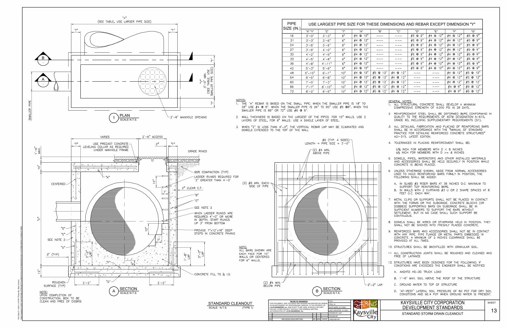
PIPESIZE (IN.)
USE LARGEST PIPE SIZE FOR THESE DIMENSIONS AND REBAR EXCEPT DIMENSION "Y"
"X" "Y" "Z" "T" "A" "B" "C" "D" "E" "F" "G"
SCALE:STANDARD CLEANOUT
N.T.S. (TYPE 1)
-A
-B
SCALE:1 PLANN.T.S.
SCALE:A SECTIONN.T.S. SCALE:B SECTION
N.T.S.
REUSE OF DRAWINGSTHIS DOCUMENT, AND THE IDEAS AND DESIGNS INCORPORATED HEREIN,AS AN INSTRUMENT OF PROFESSIONAL SERVICE, IS THE PROPERY OFJ-U-B ENGINEERS, Inc. AND IS NOT TO BE USED, IN WHOLE OR PART,FOR ANY OTHER PROJECT WITHOUT THE EXPRESS WRITTENAUTHORIZATION OF J-U-B ENGINEERS, Inc.
REVISION DESCRIPTIONNO.
PROJ. #:
DESIGN BY:
DRAWN BY:
CHECKED BY:APR. DATEBY
SHEETFILE:
LAST UPDATED: 2/1/2021
PLOT DATE: 2/11/2021
Plo
t Dat
e:2/
11/2
021
3:18
PM
Plo
tted
By:
Mar
k Je
nkin
s
Dat
e C
reat
ed:4
/1/2
020
\\KA
YS
\PU
BLI
C\P
RO
JEC
TS
\JU
B\K
AY
SV
ILLE
\ST
AN
DA
RD
S\C
AD
\13-
ST
OR
M D
RA
IN C
LEA
NO
UT
.DW
G
KAYSVILLE CITY CORPORATIONDEVELOPMENT STANDARDSSTANDARD STORM DRAIN CLEANOUT
13KEF
AutoCAD SHX Text
GENERAL NOTES: 1. ALL STRUCTURAL CONCRETE SHALL DEVELOP A MINIMUM ALL STRUCTURAL CONCRETE SHALL DEVELOP A MINIMUM COMPRESSIVE STRENGTH OF 4,000 PSI IN 28 DAYS. 2. REINFORCEMENT STEEL SHALL BE DEFORMED BARS CONFORMING IN REINFORCEMENT STEEL SHALL BE DEFORMED BARS CONFORMING IN QUALITY TO THE REQUIREMENTS OF ASTM DESIGNATION A-615, GRADE 60, INCLUDING SUPPLEMENTARY REQUIREMENTS (S1). 3. ALL DETAILING, FABRICATION AND PLACING OF REINFORCING BARS ALL DETAILING, FABRICATION AND PLACING OF REINFORCING BARS SHALL BE IN ACCORDANCE WITH THE "MANUAL OF STANDARD PRACTICE FOR DETAILING REINFORCED CONCRETE STRUCTURES" ACI-315, LATEST EDITION. 4. TOLERANCES IN PLACING REINFORCEMENT SHALL BE: TOLERANCES IN PLACING REINFORCEMENT SHALL BE: ± INCH FOR MEMBERS WITH D < 8 INCHES 38 INCH FOR MEMBERS WITH D < 8 INCHES ± INCH FOR MEMBERS WITH D >= 8 INCHES 12 INCH FOR MEMBERS WITH D >= 8 INCHES 5. DOWELS, PIPES, WATERSTOPS AND OTHER INSTALLED MATERIALS DOWELS, PIPES, WATERSTOPS AND OTHER INSTALLED MATERIALS AND ACCESSORIES SHALL BE HELD SECURELY IN POSITION WHILE CONCRETE IS BEING PLACED. 6. UNLESS OTHERWISE SHOWN, ASIDE FROM NORMAL ACCESSORIES UNLESS OTHERWISE SHOWN, ASIDE FROM NORMAL ACCESSORIES USED TO HOLD REINFORCING BARS FIRMLY IN POSITION, THE FOLLOWING SHALL BE ADDED: A. IN SLABS #5 RISER BARS AT 36 INCHES O.C. MAXIMUM TO IN SLABS #5 RISER BARS AT 36 INCHES O.C. MAXIMUM TO SUPPORT TOP REINFORCING BARS. B. IN WALLS WITH 2 CURTAINS #3 U OR Z SHAPE SPACES AT 6 IN WALLS WITH 2 CURTAINS #3 U OR Z SHAPE SPACES AT 6 FEET O.C. EACH WAY. 7. METAL CLIPS OR SUPPORTS SHALL NOT BE PLACED IN CONTACT METAL CLIPS OR SUPPORTS SHALL NOT BE PLACED IN CONTACT WITH THE FORMS OR THE SUBGRADE. CONCRETE BLOCKS (OR DOBBIES) SUPPORTING BARS ON SUBGRADE SHALL BE IN SUFFICIENT NUMBERS TO SUPPORT THE BARS WITHOUT SETTLEMENT, BUT IN NO CASE SHALL SUCH SUPPORT BE CONTINUOUS. 8. DOWELS SHALL BE WIRED OR OTHERWISE HELD IN POSITION. THEY DOWELS SHALL BE WIRED OR OTHERWISE HELD IN POSITION. THEY SHALL NOT BE SHOVED INTO FRESHLY PLACED CONCRETE. 9. REINFORCED BARS AND ACCESSORIES SHALL NOT BE IN CONTACT REINFORCED BARS AND ACCESSORIES SHALL NOT BE IN CONTACT WITH ANY PIPE, PIPE FLANGE OR METAL PARTS EMBEDDED IN CONCRETE. A MINIMUM OF 2 INCHES CLEARANCE SHALL BE PROVIDED AT ALL TIMES. 10. STRUCTURES SHALL BE BACKFILLED WITH GRANULAR SOIL. STRUCTURES SHALL BE BACKFILLED WITH GRANULAR SOIL. 11. ALL CONSTRUCTION JOINTS SHALL BE ROUGHED AND CLEANED AND ALL CONSTRUCTION JOINTS SHALL BE ROUGHED AND CLEANED AND FREE OF LAITANCE. 12. STRUCTURES HAVE BEEN DESIGNED FOR THE FOLLOWING; IF STRUCTURES HAVE BEEN DESIGNED FOR THE FOLLOWING; IF CONDITIONS ARE EXCEEDED THE ENGINEER SHALL BE NOTIFIED. A. AASHTO HS-20 TRUCK LOAD AASHTO HS-20 TRUCK LOAD B. 1'-6" MAX. SOIL ABOVE THE ROOF OF THE STRUCTURE 1'-6" MAX. SOIL ABOVE THE ROOF OF THE STRUCTURE C. GROUND WATER TO TOP OF STRUCTURE GROUND WATER TO TOP OF STRUCTURE D. "AT-REST" LATERAL SOIL PRESSURE OF 60 PCF FOR DRY SOIL "AT-REST" LATERAL SOIL PRESSURE OF 60 PCF FOR DRY SOIL CONDITIONS AND 92.4 PCF WHEN GROUND WATER IS PRESENT.
AutoCAD SHX Text
NOTES: 1. THE "H" REBAR IS BASED ON THE SMALL PIPE. WHEN THE SMALLER PIPE IS 18" TO THE "H" REBAR IS BASED ON THE SMALL PIPE. WHEN THE SMALLER PIPE IS 18" TO 36" USE #4 @ 6". WHEN THE SMALLER PIPE IS 24" TO 60" USE #5 @6". WHEN THE SMALLER PIPE IS 66" OR 72" USE #6 @ 6". 2. WALL THICKNESS IS BASED ON THE LARGEST OF THE PIPES. FOR 10" WALLS, USE 2 WALL THICKNESS IS BASED ON THE LARGEST OF THE PIPES. FOR 10" WALLS, USE 2 LAYERS OF STEEL, FOR 6" WALLS, USE A SINGLE LAYER OF STEEL. 3. WHEN "Z" IS LESS THAN 4'-0", THE VERTICAL REBAR LAP MAY BE ELIMINATED AND WHEN "Z" IS LESS THAN 4'-0", THE VERTICAL REBAR LAP MAY BE ELIMINATED AND DOWELS EXTENDED TO THE TOP OF THE WALL.
AutoCAD SHX Text
USE PRECAST CONCRETE LEVELING COLLAR AS REQUIRED UNDER MANHOLE FRAME
AutoCAD SHX Text
CENTERED
AutoCAD SHX Text
"D"
AutoCAD SHX Text
"E"
AutoCAD SHX Text
SEE NOTE 2
AutoCAD SHX Text
"D"
AutoCAD SHX Text
"F"
AutoCAD SHX Text
"G"
AutoCAD SHX Text
96% COMPACTION (TYP)
AutoCAD SHX Text
LADDER RUNGS REQUIRED FOR "Z" GREATER THAN 4'-0"
AutoCAD SHX Text
"B"
AutoCAD SHX Text
"C"
AutoCAD SHX Text
SEE NOTE 2
AutoCAD SHX Text
WHEN LADDER RUNGS ARE REQUIRED 4'-0" OR MORE IN DEPTH, START RUNGS UP 3" FROM BOTTOM
AutoCAD SHX Text
PROVIDE 7"x12"x16" DEEP STEPS IN CONCRETE PAVING
AutoCAD SHX Text
CONCRETE FILL TO I.D.12 I.D.
AutoCAD SHX Text
ROUGHEN SURFACE (TYP)
AutoCAD SHX Text
GRADE RINGS
AutoCAD SHX Text
2'-2" LAP
AutoCAD SHX Text
(2) #4 MIN. BELOW PIPE
AutoCAD SHX Text
(3) #5 MIN. EACH SIDE OF PIPE
AutoCAD SHX Text
(2) #4 MIN. ABOVE PIPE
AutoCAD SHX Text
#5 (TYP. 4 SIDES) LENGTH = PIPE SIZE + 3'-0"
AutoCAD SHX Text
NOTE: ALL BARS SHOWN ARE EACH FACE FOR 10" WALLS OR CENTERED FOR 6" WALLS.
AutoCAD SHX Text
NOTE: UPON COMPLETION OF CONSTRUCTION, BOX TO BE CLEAN AND FREE OF DEBRIS.
AutoCAD SHX Text
2'-6" MANHOLE OPENING
AutoCAD SHX Text
18
AutoCAD SHX Text
3'-0"
AutoCAD SHX Text
3'-3"
AutoCAD SHX Text
6"
AutoCAD SHX Text
#4 @ 12"
AutoCAD SHX Text
---
AutoCAD SHX Text
---
AutoCAD SHX Text
#5 @ 9"
AutoCAD SHX Text
#4 @ 12"
AutoCAD SHX Text
#4 @ 12"
AutoCAD SHX Text
#5 @ 9"
AutoCAD SHX Text
21
AutoCAD SHX Text
3'-3"
AutoCAD SHX Text
3'-6"
AutoCAD SHX Text
6"
AutoCAD SHX Text
#4 @ 12"
AutoCAD SHX Text
---
AutoCAD SHX Text
---
AutoCAD SHX Text
#5 @ 9"
AutoCAD SHX Text
#4 @ 12"
AutoCAD SHX Text
#4 @ 12"
AutoCAD SHX Text
#5 @ 9"
AutoCAD SHX Text
24
AutoCAD SHX Text
3'-6"
AutoCAD SHX Text
3'-9"
AutoCAD SHX Text
6"
AutoCAD SHX Text
#4 @ 12"
AutoCAD SHX Text
---
AutoCAD SHX Text
---
AutoCAD SHX Text
#5 @ 9"
AutoCAD SHX Text
#4 @ 12"
AutoCAD SHX Text
#4 @ 12"
AutoCAD SHX Text
#5 @ 9"
AutoCAD SHX Text
27
AutoCAD SHX Text
3'-9"
AutoCAD SHX Text
4'-0"
AutoCAD SHX Text
6"
AutoCAD SHX Text
#4 @ 12"
AutoCAD SHX Text
---
AutoCAD SHX Text
---
AutoCAD SHX Text
#5 @ 9"
AutoCAD SHX Text
#4 @ 12"
AutoCAD SHX Text
#4 @ 12"
AutoCAD SHX Text
#5 @ 9"
AutoCAD SHX Text
30
AutoCAD SHX Text
4'-2"
AutoCAD SHX Text
4'-5"
AutoCAD SHX Text
6"
AutoCAD SHX Text
#4 @ 12"
AutoCAD SHX Text
---
AutoCAD SHX Text
---
AutoCAD SHX Text
#5 @ 9"
AutoCAD SHX Text
#4 @ 12"
AutoCAD SHX Text
#4 @ 12"
AutoCAD SHX Text
#5 @ 9"
AutoCAD SHX Text
33
AutoCAD SHX Text
4'-5"
AutoCAD SHX Text
4'-8"
AutoCAD SHX Text
6"
AutoCAD SHX Text
#4 @ 12"
AutoCAD SHX Text
---
AutoCAD SHX Text
---
AutoCAD SHX Text
#5 @ 9"
AutoCAD SHX Text
#4 @ 12"
AutoCAD SHX Text
#4 @ 12"
AutoCAD SHX Text
#5 @ 9"
AutoCAD SHX Text
36
AutoCAD SHX Text
4'-8"
AutoCAD SHX Text
4'-11"
AutoCAD SHX Text
6"
AutoCAD SHX Text
#4 @ 12"
AutoCAD SHX Text
---
AutoCAD SHX Text
---
AutoCAD SHX Text
#5 @ 9"
AutoCAD SHX Text
#4 @ 12"
AutoCAD SHX Text
#4 @ 12"
AutoCAD SHX Text
#5 @ 9"
AutoCAD SHX Text
42
AutoCAD SHX Text
5'-3"
AutoCAD SHX Text
5'-6"
AutoCAD SHX Text
6"
AutoCAD SHX Text
#4 @ 12"
AutoCAD SHX Text
---
AutoCAD SHX Text
---
AutoCAD SHX Text
#5 @ 9"
AutoCAD SHX Text
#4 @ 12"
AutoCAD SHX Text
#4 @ 12"
AutoCAD SHX Text
#5 @ 9"
AutoCAD SHX Text
48
AutoCAD SHX Text
5'-10"
AutoCAD SHX Text
6'-1"
AutoCAD SHX Text
10"
AutoCAD SHX Text
#4 @ 12"
AutoCAD SHX Text
#5 @ 12"
AutoCAD SHX Text
#4 @ 12"
AutoCAD SHX Text
---
AutoCAD SHX Text
---
AutoCAD SHX Text
#4 @ 12"
AutoCAD SHX Text
#5 @ 12"
AutoCAD SHX Text
54
AutoCAD SHX Text
6'-5"
AutoCAD SHX Text
6'-8"
AutoCAD SHX Text
10"
AutoCAD SHX Text
#4 @ 12"
AutoCAD SHX Text
#5 @ 12"
AutoCAD SHX Text
#4 @ 12"
AutoCAD SHX Text
---
AutoCAD SHX Text
---
AutoCAD SHX Text
#4 @ 12"
AutoCAD SHX Text
#5 @ 12"
AutoCAD SHX Text
60
AutoCAD SHX Text
7'-0"
AutoCAD SHX Text
7'-3"
AutoCAD SHX Text
10"
AutoCAD SHX Text
#4 @ 12"
AutoCAD SHX Text
#5 @ 12"
AutoCAD SHX Text
#4 @ 12"
AutoCAD SHX Text
---
AutoCAD SHX Text
---
AutoCAD SHX Text
#4 @ 12"
AutoCAD SHX Text
#5 @ 12"
AutoCAD SHX Text
66
AutoCAD SHX Text
7'-7"
AutoCAD SHX Text
8'-10"
AutoCAD SHX Text
10"
AutoCAD SHX Text
#4 @ 12"
AutoCAD SHX Text
#5 @ 12"
AutoCAD SHX Text
#4 @ 12"
AutoCAD SHX Text
---
AutoCAD SHX Text
---
AutoCAD SHX Text
#4 @ 9"
AutoCAD SHX Text
#5 @ 12"
AutoCAD SHX Text
72
AutoCAD SHX Text
8'-2"
AutoCAD SHX Text
8'-5"
AutoCAD SHX Text
10"
AutoCAD SHX Text
#4 @ 12"
AutoCAD SHX Text
#5 @ 12"
AutoCAD SHX Text
#4 @ 12"
AutoCAD SHX Text
---
AutoCAD SHX Text
---
AutoCAD SHX Text
#4 @ 9"
AutoCAD SHX Text
#5 @ 12"
AutoCAD SHX Text
"A"
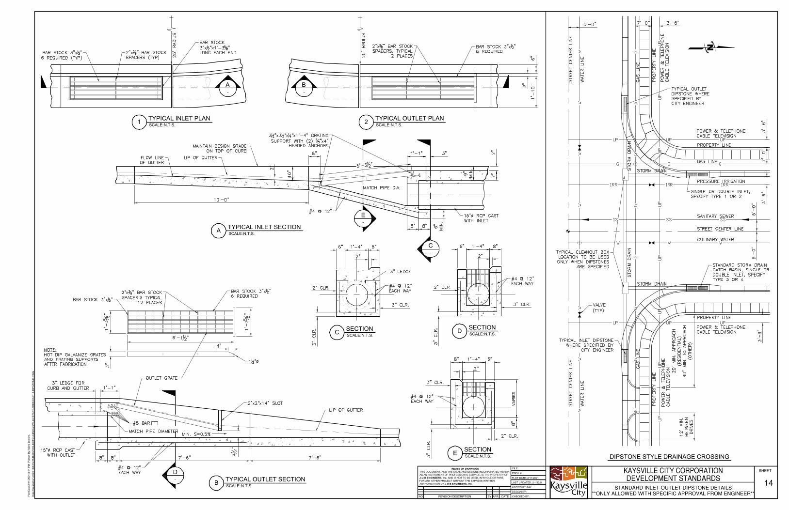
-A
-B
SCALE:A TYPICAL INLET SECTIONN.T.S.
SCALE:1 TYPICAL INLET PLANN.T.S. SCALE:2 TYPICAL OUTLET PLAN
N.T.S.
SCALE:B TYPICAL OUTLET SECTIONN.T.S.
SCALE:C SECTIONN.T.S. SCALE:D SECTION
N.T.S.
SCALE:E SECTIONN.T.S.
-C
-E
-D
N
DIPSTONE STYLE DRAINAGE CROSSING
REUSE OF DRAWINGSTHIS DOCUMENT, AND THE IDEAS AND DESIGNS INCORPORATED HEREIN,AS AN INSTRUMENT OF PROFESSIONAL SERVICE, IS THE PROPERTY OFJ-U-B ENGINEERS, Inc. AND IS NOT TO BE USED, IN WHOLE OR PART,FOR ANY OTHER PROJECT WITHOUT THE EXPRESS WRITTENAUTHORIZATION OF J-U-B ENGINEERS, Inc.
REVISION DESCRIPTIONNO.
PROJ. #:
DESIGN BY:
DRAWN BY:
CHECKED BY:APR. DATEBY
SHEETFILE:
LAST UPDATED: 2/1/2021
PLOT DATE: 2/11/2021
Plo
t Dat
e:2/
11/2
021
3:21
PM
Plo
tted
By:
Mar
k Je
nkin
s
Dat
e C
reat
ed:4
/1/2
020
\\KA
YS
\PU
BLI
C\P
RO
JEC
TS
\JU
B\K
AY
SV
ILLE
\ST
AN
DA
RD
S\C
AD
\14-
DIP
ST
ON
E.D
WG
KAYSVILLE CITY CORPORATIONDEVELOPMENT STANDARDS
STANDARD INLET-OUTLET DIPSTONE DETAILS**ONLY ALLOWED WITH SPECIFIC APPROVAL FROM ENGINEER**
14KEF
AutoCAD SHX Text
25' RADIUS
AutoCAD SHX Text
25' RADIUS
AutoCAD SHX Text
MATCH PIPE DIA.
AutoCAD SHX Text
MIN. S=0.5%
AutoCAD SHX Text
NOTE: HOT DIP GALVANIZE GRATES AND FRATING SUPPORTS AFTER FABRICATION
AutoCAD SHX Text
LIP OF GUTTER
AutoCAD SHX Text
2"x2"x14" SLOT
AutoCAD SHX Text
OUTLET GRATE
AutoCAD SHX Text
BAR STOCK 3"x "12"
AutoCAD SHX Text
2"x " BAR STOCK 38" BAR STOCK SPACER'S TYPICAL 12 PLACES
AutoCAD SHX Text
BAR STOCK 3"x " 12" 6 REQUIRED
AutoCAD SHX Text
1 " 12"
AutoCAD SHX Text
#4 @ 12" EACH WAY
AutoCAD SHX Text
MATCH PIPE DIAMETER
AutoCAD SHX Text
15" RCP CASTWITH OUTLET
AutoCAD SHX Text
#4 @ 12" EACH WAY
AutoCAD SHX Text
#4 @ 12" EACH WAY
AutoCAD SHX Text
#4 @ 12" EACH WAY
AutoCAD SHX Text
3" LEDGE
AutoCAD SHX Text
15" RCP CASTWITH INLET
AutoCAD SHX Text
#4 @ 12"
AutoCAD SHX Text
LIP OF GUTTER
AutoCAD SHX Text
MAINTAIN DESIGN GRADE ON TOP OF CURB
AutoCAD SHX Text
FLOW LINE OF GUTTER
AutoCAD SHX Text
3 "x3 "x "x1'-4" GRATING 12"x3 "x "x1'-4" GRATING 12"x "x1'-4" GRATING 14"x1'-4" GRATING SUPPORT WITH (2) "x4" 58"x4" HEADED ANCHORS
AutoCAD SHX Text
BAR STOCK 3"x " 12" 6 REQUIRED
AutoCAD SHX Text
2"x " BAR STOCK 38" BAR STOCK SPACERS, TYPICAL 2 PLACES
AutoCAD SHX Text
BAR STOCK 3"x "x1'-3 " 12"x1'-3 " 58" LONG EACH END
AutoCAD SHX Text
BAR STOCK 3"x " 12" 6 REQUIRED (TYP)
AutoCAD SHX Text
2"x " BAR STOCK 38" BAR STOCK SPACERS (TYP)
AutoCAD SHX Text
PROPERTY LINE
AutoCAD SHX Text
STREET CENTER LINE
AutoCAD SHX Text
TYPICAL OUTLET DIPSTONE WHERE SPECIFIED BY CITY ENGINEER
AutoCAD SHX Text
TYPICAL CLEANOUT BOX LOCATION TO BE USED ONLY WHEN DIPSTONES ARE SPECIFIED
AutoCAD SHX Text
SINGLE OR DOUBLE INLET, SPECIFY TYPE 1 OR 2
AutoCAD SHX Text
STANDARD STORM DRAIN CATCH BASIN, SINGLE OR DOUBLE INLET, SPECIFY TYPE 3 OR 4
AutoCAD SHX Text
VALVE (TYP)
AutoCAD SHX Text
TYPICAL INLET DIPSTONE WHERE SPECIFIED BY CITY ENGINEER
AutoCAD SHX Text
SANITARY SEWER
AutoCAD SHX Text
CULINARY WATER
AutoCAD SHX Text
PRESSURE IRRIGATION
AutoCAD SHX Text
GAS LINE
AutoCAD SHX Text
PROPERTY LINE
AutoCAD SHX Text
GAS LINE
AutoCAD SHX Text
WATER LINE
AutoCAD SHX Text
STREET CENTER LINE
AutoCAD SHX Text
WATER LINE
AutoCAD SHX Text
STREET CENTER LINE
AutoCAD SHX Text
PROPERTY LINE
AutoCAD SHX Text
GAS LINE
AutoCAD SHX Text
STORM DRAIN
AutoCAD SHX Text
STORM DRAIN
AutoCAD SHX Text
STORM DRAIN
AutoCAD SHX Text
STORM DRAIN
AutoCAD SHX Text
POWER & TELEPHONE CABLE TELEVISION
AutoCAD SHX Text
POWER & TELEPHONE CABLE TELEVISION
AutoCAD SHX Text
PROPERTY LINE
AutoCAD SHX Text
POWER & TELEPHONE CABLE TELEVISION
AutoCAD SHX Text
POWER & TELEPHONE CABLE TELEVISION

REUSE OF DRAWINGSTHIS DOCUMENT, AND THE IDEAS AND DESIGNS INCORPORATED HEREIN,AS AN INSTRUMENT OF PROFESSIONAL SERVICE, IS THE PROPERY OFJ-U-B ENGINEERS, Inc. AND IS NOT TO BE USED, IN WHOLE OR PART,FOR ANY OTHER PROJECT WITHOUT THE EXPRESS WRITTENAUTHORIZATION OF J-U-B ENGINEERS, Inc.
REVISION DESCRIPTIONNO.
PROJ. #:
DESIGN BY:
DRAWN BY:
CHECKED BY:APR. DATEBY
SHEETFILE:
LAST UPDATED: 2/1/2021
PLOT DATE: 2/11/2021
Plo
t Dat
e:2/
11/2
021
3:21
PM
Plo
tted
By:
Mar
k Je
nkin
s
Dat
e C
reat
ed:4
/1/2
020
\\KA
YS
\PU
BLI
C\P
RO
JEC
TS
\JU
B\K
AY
SV
ILLE
\ST
AN
DA
RD
S\C
AD
\15-
ST
RE
ET
IMP
RO
VE
ME
NT
S-P
OW
ER
-CA
BLE
.DW
G
KAYSVILLE CITY CORPORATIONDEVELOPMENT STANDARDSSTANDARD STREET IMPROVEMENTS
POWER AND CABLE TELEVISION LINES
15KEF
N
SCALE:TYPICAL STREET IMPROVEMENT PLAN
N.T.S.
AutoCAD SHX Text
HIGH VOLTAGE JUNCTION VAULT
AutoCAD SHX Text
POWER
AutoCAD SHX Text
POWER
AutoCAD SHX Text
PROPERTY LINE
AutoCAD SHX Text
STORM DRAIN
AutoCAD SHX Text
WATER LINE
AutoCAD SHX Text
SANITARY SEWER
AutoCAD SHX Text
PRESSURE IRRIGATION
AutoCAD SHX Text
GAS LINE
AutoCAD SHX Text
STREET CENTER LINE
AutoCAD SHX Text
NOTES: 1. POWER AND CABLE TELEVISION CONDUITS TO BE INSTALLED IN SEPARATE POWER AND CABLE TELEVISION CONDUITS TO BE INSTALLED IN SEPARATE TRENCHES. POWER NEEDS TO BE ON THE STREET SIDE. ALL OTHER UTILITIES ON THE PROPERTY SIDE. 2. KAYSVILLE CITY POWER WILL SUPPLY POWER CONDUIT. KAYSVILLE CITY POWER WILL SUPPLY POWER CONDUIT. 3. **BACK FILL AND COMPACTION OF THE STREET CROSSING IS THE **BACK FILL AND COMPACTION OF THE STREET CROSSING IS THE RESPONSIBILTY OF THE DEVELOPER. 4. ***ANY UTILITIES STUBBED BEYOND THE PROPERTY LINE MUST MAINTAIN A ***ANY UTILITIES STUBBED BEYOND THE PROPERTY LINE MUST MAINTAIN A MINIMUM DEPTH OF 48". 5. GAS SHALL NOT BE ALLOWED IN JOINT TRENCH. GAS SHALL NOT BE ALLOWED IN JOINT TRENCH. SHALL NOT BE ALLOWED IN JOINT TRENCH. BE ALLOWED IN JOINT TRENCH. 6. ALL UTILITIES OTHER THAN POWER SHALL BE ROUTED AROUND AND NOT ALL UTILITIES OTHER THAN POWER SHALL BE ROUTED AROUND AND NOT UNDERNEATH POWER VAULTS AND TRANSFORMERS. THERE SHALL BE NO JUNCTIONS OR TERMINATION OF THESE OTHER UTILITIES IN THESE LOCATIONS. 7. TRENCH SHARING WITH POWER NOT ALLOWED UNLESS ELEVATION STAGGERED.TRENCH SHARING WITH POWER NOT ALLOWED UNLESS ELEVATION STAGGERED.
AutoCAD SHX Text
UTILITY EASEMENT
AutoCAD SHX Text
UTILITY EASEMENT
AutoCAD SHX Text
TELEPHONE & CABLE TELEVISION
AutoCAD SHX Text
TELEPHONE & CABLE TELEVISION

TYPICAL TRENCH SECTIONS
SCALE:3 TURF SURFACEN.T.S.
SCALE:2 GRAVEL SURFACEN.T.S.
SCALE:1 ASPHALT SURFACEN.T.S.
POWER AND CABLE T.V. TRENCH SECTION
REUSE OF DRAWINGSTHIS DOCUMENT, AND THE IDEAS AND DESIGNS INCORPORATED HEREIN,AS AN INSTRUMENT OF PROFESSIONAL SERVICE, IS THE PROPERY OFJ-U-B ENGINEERS, Inc. AND IS NOT TO BE USED, IN WHOLE OR PART,FOR ANY OTHER PROJECT WITHOUT THE EXPRESS WRITTENAUTHORIZATION OF J-U-B ENGINEERS, Inc.
REVISION DESCRIPTIONNO.
PROJ. #:
DESIGN BY:
DRAWN BY:
CHECKED BY:APR. DATEBY
SHEETFILE:
LAST UPDATED: 2/1/2021
PLOT DATE: 2/11/2021
Plo
t Dat
e:2/
11/2
021
3:29
PM
Plo
tted
By:
Mar
k Je
nkin
s
Dat
e C
reat
ed:4
/1/2
020
\\KA
YS
\PU
BLI
C\P
RO
JEC
TS
\JU
B\K
AY
SV
ILLE
\ST
AN
DA
RD
S\C
AD
\16-
TR
EN
CH
SE
CT
ION
S.D
WG
KAYSVILLE CITY CORPORATIONDEVELOPMENT STANDARDS
TYPICAL TRENCH SECTIONS16
KEF
AutoCAD SHX Text
NOTES: 1. SLOPE TRENCH TO MEET OSHA REQUIREMENTS SLOPE TRENCH TO MEET OSHA REQUIREMENTS (LATEST EDITION) OR USE TRENCH BOX. 2. FOUNDATION AND BEDDING MATERIAL AS REQUIRED. FOUNDATION AND BEDDING MATERIAL AS REQUIRED. 3. INSTALL PIPELINES ON STABLE FOUNDATION WITH INSTALL PIPELINES ON STABLE FOUNDATION WITH UNIFORM BEARING FOR FULL LENGTH OF BARREL, EXCAVATE IN BEDDING FOR ALL PIPE JOINTS. 4. IF GRAVEL MATERIAL IS USED FOR PIPE IF GRAVEL MATERIAL IS USED FOR PIPE EMBEDMENT, FABRIC IS TO BE USED ON TOP OF GRAVEL BEFORE BACKFILLING TRENCH. 5. FOR POTHOLES: USE STATE SPEC. FLOWABLE FILL FOR POTHOLES: USE STATE SPEC. FLOWABLE FILL PER SECTION 03575 UDOT SPECS. UP TO ASPHALT GRADE AND THEN PAVE PROPER ASPHALT DEPTH 6. THE INDIVIDUAL RESPONSIBLE FOR THE COMPLETE THE INDIVIDUAL RESPONSIBLE FOR THE COMPLETE REPAIR OF ALL ASPHALT SURFACES SHALL ALSO CRACK SEAL AND SURFACE TREATMENT THE ENTIRE EXCAVATED AREA AS DETERMINED BY KAYSVILLE CITY. ALL JOINTS SHALL BE CRACK SEALED PRIOR TO SLURRY SEAL. CRACK SEAL MUST BE INSPECTED BEFORE SLURRY SEAL IS APPLIED. SLURRY SEAL SHALL BE A TYPE 2 SLURRY WITH SAND.
AutoCAD SHX Text
96% COMPACTION (TYP)
AutoCAD SHX Text
90% COMPACTION (TYP)
AutoCAD SHX Text
CUT ASPHALT TO WIDTH OF TRENCH, CONSTRUCT PIPELINE AND RESTORE SUB-SURFACE. AFTER TRENCH BACKFILL, CUT ASPHALT 18" WIDER THAN TRENCH ON EACH SIDE THAT ASPHALT EXISTS. REMOVE ASPHALT AND FINISH RESTORATION
AutoCAD SHX Text
GROUND SURFACE
AutoCAD SHX Text
STREET SIDE
AutoCAD SHX Text
PROPERTY SIDE
AutoCAD SHX Text
NOTE: ANY UTILITIES STUBBED BEYOND THE PROPERTY LINE MUST HAVE A MINIMUM DEPTH OF 48".
AutoCAD SHX Text
(2) 4" KAYSVILLE CITY POWER CONDUITS
AutoCAD SHX Text
UNDISTURBED SOIL
AutoCAD SHX Text
(1) 2" CABLE TELEVISION CONDUIT
AutoCAD SHX Text
OTHER BURIED UTILITIES
AutoCAD SHX Text
UNDISTURBED SOIL
AutoCAD SHX Text
BACKFILL AND COMPACTION WITHIN THE ROADWAY SHALL CONFORM TO THE SPECIFICATIONS OF THE PAVEMENT DESIGN

REUSE OF DRAWINGSTHIS DOCUMENT, AND THE IDEAS AND DESIGNS INCORPORATED HEREIN,AS AN INSTRUMENT OF PROFESSIONAL SERVICE, IS THE PROPERY OFJ-U-B ENGINEERS, Inc. AND IS NOT TO BE USED, IN WHOLE OR PART,FOR ANY OTHER PROJECT WITHOUT THE EXPRESS WRITTENAUTHORIZATION OF J-U-B ENGINEERS, Inc.
REVISION DESCRIPTIONNO.
PROJ. #:
DESIGN BY:
DRAWN BY:
CHECKED BY:APR. DATEBY
SHEETFILE:
LAST UPDATED: 2/1/2021
PLOT DATE: 2/11/2021
Plo
t Dat
e:2/
11/2
021
3:25
PM
Plo
tted
By:
Mar
k Je
nkin
s
Dat
e C
reat
ed:5
/7/2
020
\\KA
YS
\PU
BLI
C\P
RO
JEC
TS
\JU
B\K
AY
SV
ILLE
\ST
AN
DA
RD
S\C
AD
\17-
FIB
ER
.DW
G
KAYSVILLE CITY CORPORATIONDEVELOPMENT STANDARDS
STANDARD FIBER DETAILS17
JDM
SRM
SRM
SCALE:TYPICAL LOT LAYOUT
N.T.S.
SCALE:PROFILE BOX VIEW
N.T.S.
AutoCAD SHX Text
LOT #
AutoCAD SHX Text
LOT #
AutoCAD SHX Text
LOT #
AutoCAD SHX Text
LOT #
AutoCAD SHX Text
4' SIDEWALK
AutoCAD SHX Text
PARK STRIP
AutoCAD SHX Text
STANDARD CURB & GUTTER
AutoCAD SHX Text
STANDARD RECTANGULAR BOX INSTALLED EVERY OTHER LOT LINE. (TYP)
AutoCAD SHX Text
STANDARD RECTANGULAR BOX 21 "x15 "x12 " 58"x15 "x12 " 34"x12 " 14" BLACK POLYOLEFIN (TYP)
AutoCAD SHX Text
4 WAY FIBER HDPE MICRODUCT 30" COVER (TYP)
AutoCAD SHX Text
STANDARD RECTANGULAR BOX 21 "x15 "x12 " 58"x15 "x12 " 34"x12 " 14" BLACK POLYOLEFIN
AutoCAD SHX Text
COMPACTED BACK FILL
AutoCAD SHX Text
UNDISTURBED SOIL

2021
LOW IMPACT DEVELOPMENT
MANUAL
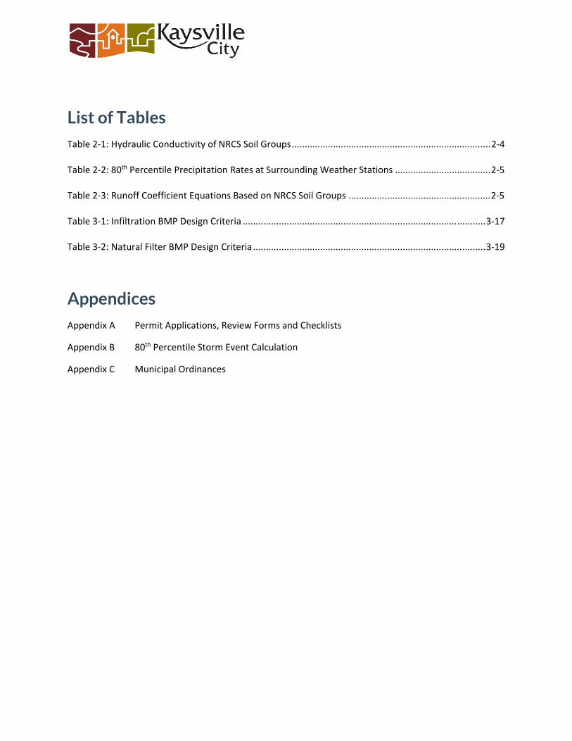
List of Tables
Table 2-1: Hydraulic Conductivity of NRCS Soil Groups ............................................................................. 2-4
Table 2-2: 80th Percentile Precipitation Rates at Surrounding Weather Stations ..................................... 2-5
Table 2-3: Runoff Coefficient Equations Based on NRCS Soil Groups ....................................................... 2-5
Table 3-1: Infiltration BMP Design Criteria .............................................................................................. 3-17
Table 3-2: Natural Filter BMP Design Criteria .......................................................................................... 3-19
Appendices
Appendix A Permit Applications, Review Forms and Checklists
Appendix B 80th Percentile Storm Event Calculation
Appendix C Municipal Ordinances

Section 1 > Introduction
1 1-1 KAYSVILLE CITY >> Low Impact Development Manual >> 2021
1. Introduction 1.1 Purpose
The purpose of this manual is to provide some basic information and understanding of how new construction and re-development, in accordance with Kaysville City ordinances, can fulfill the requirements outlined in Utah’s Permit for Discharges from Small Municipal Separate Storm Sewer Systems (MS4). Specific audiences include developers, designers, contractors and homeowners. This manual may not detail all Kaysville City, State or Federal requirements.
1.2 Background
Polluted storm water runoff is often transported to MS4s and ultimately discharges into local rivers and streams without treatment. EPA’s Storm Water Phase II Rule establishes an MS4 storm water management program that is intended to improve the Nation’s waterways by reducing the quantity of pollutants that are introduced into storm sewer systems during storm events. Common pollutants include oil and grease from roadways, roadway salts and deicing materials, pesticides and fertilizers from lawns, sediment from construction sites, and carelessly discarded trash, such as cigarette butts, paper wrappers, and plastic bottles. When deposited into nearby waterways through MS4 discharges, these pollutants can impair the waterways, thereby discouraging use of the resource, contaminating water supplies, and interfering with the habitat for fish, other aquatic organisms, and wildlife.
In 1990, EPA promulgated rules establishing Phase I of the National Pollutant Discharge Elimination System (NPDES) storm water program. The Phase I program for MS4s requires operators of “medium” and “large” MS4s, that is, those that generally serve populations of 100,000 or greater, to implement a storm water management program as a means to control polluted discharges from these MS4s. The Storm Water Phase II Rule extends coverage of the NPDES storm water program to certain “small” MS4s but takes a slightly different approach to how the storm water management program is developed and implemented. Kaysville City is currently regulated under the General Permit for Discharges from Small MS4s.
1.3 Scope
The scope of this manual is to provide information relative to the State of Utah proposed UPDES permit section 4.2.5.3.2 which states “…the program shall include a process which requires the evaluation of Low Impact Development (LID) approach…”, furthermore, “If an LID approach cannot be utilized, the Permittee must document an explanation of the reasons preventing this approach and the rationale for the chosen alternative controls on a case by case basis for the project.”
All determinations and approvals for LID designs and plans shall be made at the sole discretion of the City.
Section 2 > LID Principles
1 2-1 KAYSVILLE CITY >> Low Impact Development Manual >> 2021
2. Low Impact Development Principles
2.1 What is Low Impact development
As defined in the State of Utah’s “A Guide to Low Impact Development within Utah”, “ LID refers to engineered systems, either structural or natural, that use or mimic natural processes to promote infiltration, evapotranspiration, and/or reuse of storm water as close to its source as possible to protect water quality and aquatic habitat.” LID generally targets minimizing runoff and may incorporate man made treatment or a combination of processes.
Low Impact Development is not a replacement for Flood Control. LID techniques target water quality. These standards should be followed in conjunction with volume and flood control efforts.
2.2 Developing a Low Impact Development Plan
New construction or redevelopments that disturb one acre or more of land, or that are part of a larger common plan of development that disturbs one acre of more, will be required to incorporate LID measures into their design plans, and submit said plans to the City for review and approval. This requirement also applies to all redevelopment of property where existing development is demolished and rebuilt, or significantly improved where said improvements disturb one acre or more of land. This requirement does not apply to remodels or additions that disturb less than one acre of land. The design plans will be subjected to a review process prior to the issuance of approvals for permits and construction.
The purpose of this manual is to provide information that can be used to select the appropriate Best Management Practices (BMPs) for a given site. This manual describes some of the minimum standards and methods for sizing and designing LID facilities. This is a minimum standard. Other more rigorous methods may be used and will be evaluated on a case-by-case basis.
To develop a plan that works with the site, it is imperative to include consideration in the conceptual design phase of the project. It is also important to have a general understanding of the specific site and any site constraints that might exist.
2.2.1 BMP Determination and Feasibility
Most long-term LID BMPs can fit into two general functional categories; BMPs that infiltrate, and BMPs that filter. Some BMPs are hybrids that can accomplish more than one function at a time. The order of priority specified below shall are according to documented feasibility and apply to all projects.
1. Infiltration (Retention of the 80th percentile storm on site) 2. Natural Filters or Treatment 3. Man Made Filters or Treatment 4. Combination of the above

Section 2 > LID Principles
2 2-2 KAYSVILLE CITY >> Low Impact Development Manual >> 2021
Because of the retention requirement, BMPs that infiltrate are given the highest priority and should be utilized until the Water Quality Volume (as detailed in section 2.2.6 below) has been captured and stored. If it is not feasible to retain and infiltrate, then treating and releasing may be considered. If compliance is infeasible, the project Site and LID Plan shall document an explanation of the reasons preventing this approach and the rationale for the chosen alternative controls on a case by case basis for the project.
Infiltration/retention will be considered feasible only when all of the following criteria can be met:
• The lowest elevation of all retention facilities shall be a minimum of three feet above the documented water table
• Retention volumes must infiltrate or evaporate within two days or 48 hours after a storm has subsided
• Retention facilities can be no closer than thirty feet from the nearest structural foundation
• Retention facilities can be no closer than fifty feet horizontally from live streams or water bodies
• Retention facilities can be no closer than five feet horizontally from roads or parking lots • If a slope in the project vicinity is steeper than 20%, there must be a geotechnical
investigation to determine a safe setback from the top of slope to allow for any infiltration to occur
• Retention facilities cannot be placed on slopes exceeding 5% • Retention shall not be allowed in areas where a licensed geotechnical engineer
determines that infiltration would adversely impact the potential for geological hazards on the project site or on neighboring parcels of land
• Side slopes on all open retention facilities must be 3:1 or flatter • A project has no land drains • Soil infiltration rates must be 0.5 inches per hour, or greater • Infiltration will not be allowed in Zones 1 or 2 of any Drinking Water Source Protection
Plan for a Public Water System • Infiltration will not be allowed in HSG soil classifications C and D

Section 2 > LID Principles
3 2-3 KAYSVILLE CITY >> Low Impact Development Manual >> 2021
2.2.2 Determining Soil Characteristics
Soil characteristics play a major role in determining LID feasibility and sizing of facilities on a site. A basic soil evaluation will need to be conducted on each site. Kaysville has elected to standardize based on the Natural Resource Conservation Service (NRCS) Hydrologic Soil Group (HSG) classifications. The NRCS system includes four hydrologic soil groups: A, B, C, and D as described below:
Group A is sand, loamy sand or sandy loam types of soils. It has low runoff potential and high infiltration rates even when thoroughly wetted. They consist chiefly of deep, well to excessively drained sands or gravels and have a high rate of water transmission.
Group B is silt loam or loam. It has a moderate infiltration rate when thoroughly wetted and consists chiefly or moderately deep to deep, moderately well to well drained soils with moderately fine to moderately coarse textures.
Group C soils are sandy clay loam. They have low infiltration rates when thoroughly wetted and consist chiefly of soils with a layer that impedes downward movement of water and soils with moderately fine to fine structure.
Group D soils are clay loam, silty clay loam, sandy clay, silty clay or clay. This HSG has the highest runoff potential. They have very low infiltration rates when thoroughly wetted and consist chiefly of clay soils with a high swelling potential, soils with a permanent high water table, soils with a claypan or clay layer at or near the surface and shallow soils over nearly impervious material.
Soils analysis may be done utilizing information obtained from the National Cooperative Soil Survey. The NRCS mapping tool is called Web Soil Survey (WSS) and provides information on drainage characteristics, water table depth (in some cases) and soil groups: https://websoilsurvey.sc.egov.usda.gov/App/WebSoilSurvey.aspx.
2.2.3 Determining Water Table Depth
Water table depth is a major factor in determining feasibility and sizing of LID techniques that infiltrate. Shallow groundwater may severely hinder or prohibit the effectiveness of infiltration. A part of any geotechnical investigations at a site should include an assessment of the high groundwater level. This should include a measurement of the existing water table at the time of the investigation and careful review of the soil structure, looking for evidence of the historic high water.
2.2.4 Determining Existing Drainage Patterns
An assessment of the existing drainage system/patterns will also assist in locating/sizing LID facilities. A detailed site survey should be conducted and existing contours developed. Preliminary site plans will include existing contours and show existing drainage patterns. Any existing storm drains should be identified, located, and elevations established. It is easier to mimic pre-development hydrology if existing drainage patterns can be maintained. Locating LID facilities
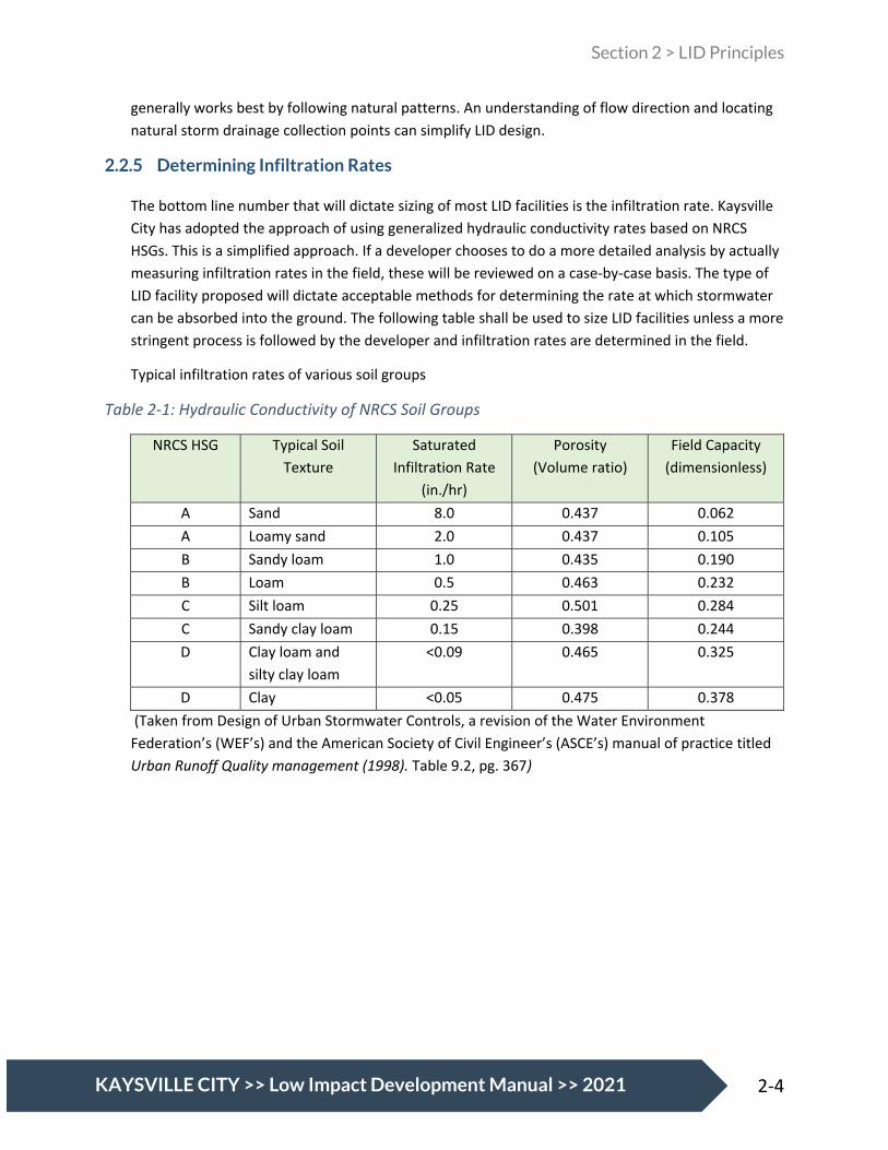
Section 2 > LID Principles
4 2-4 KAYSVILLE CITY >> Low Impact Development Manual >> 2021
generally works best by following natural patterns. An understanding of flow direction and locating natural storm drainage collection points can simplify LID design.
2.2.5 Determining Infiltration Rates
The bottom line number that will dictate sizing of most LID facilities is the infiltration rate. Kaysville City has adopted the approach of using generalized hydraulic conductivity rates based on NRCS HSGs. This is a simplified approach. If a developer chooses to do a more detailed analysis by actually measuring infiltration rates in the field, these will be reviewed on a case-by-case basis. The type of LID facility proposed will dictate acceptable methods for determining the rate at which stormwater can be absorbed into the ground. The following table shall be used to size LID facilities unless a more stringent process is followed by the developer and infiltration rates are determined in the field.
Typical infiltration rates of various soil groups
Table 2-1: Hydraulic Conductivity of NRCS Soil Groups
NRCS HSG Typical Soil Texture
Saturated Infiltration Rate
(in./hr)
Porosity (Volume ratio)
Field Capacity (dimensionless)
A Sand 8.0 0.437 0.062 A Loamy sand 2.0 0.437 0.105 B Sandy loam 1.0 0.435 0.190 B Loam 0.5 0.463 0.232 C Silt loam 0.25 0.501 0.284 C Sandy clay loam 0.15 0.398 0.244 D Clay loam and
silty clay loam <0.09 0.465 0.325
D Clay <0.05 0.475 0.378 (Taken from Design of Urban Stormwater Controls, a revision of the Water Environment Federation’s (WEF’s) and the American Society of Civil Engineer’s (ASCE’s) manual of practice titled Urban Runoff Quality management (1998). Table 9.2, pg. 367)

Section 2 > LID Principles
5 2-5 KAYSVILLE CITY >> Low Impact Development Manual >> 2021
2.2.6 Determining Water Quality Volume (WQV)
The General Permit for Discharges from Small Municipal Separate Storm Sewer Systems (MS4) Permit No. UTR090000, requires projects to “manage rainfall on-site, and prevent the off-site discharge of the precipitation from all rainfall events less than or equal to the 80th percentile rainfall event.” The volume of water generated from this 80th percentile event is being defined as the Water Quality Volume.
Table 2-2: 80th Percentile Precipitation Rates at Surrounding Weather Stations
Location Station Elevation Years of Record 80th Percentile Storm (inches)
Weber Basin USC00429346 4899.9 55 0.64 Fruit Heights US1UTDV0024 4801.8 6 0.64 Ogden Hinckley USW00024126 4470.1 25 0.50 Farmington Lower US1UTDV0001 4238.9 11 0.50 Triad Center USC00427606 4279.86 34 0.48 Salt Lake Airport USW00024127 4225.07 71 0.44
Information in Table 2-2 was taken from the Utah Climate Center. Elevations in Kaysville range from 4780 on the east side to 4230 on the west side. To simplify calculations, Kaysville City has chosen to use 0.48 inches or 0.04 feet as the 80th percentile storm depth.
The Water Quality Volume is calculated using the following equation:
WQV = RVdA
Where: WQV = 80th percentile volume, cf RV = Volumetric runoff coefficient, unitless d = 80th percentile precipitation depth, ft (convert from inches to feet if required) A = Project area or BMP drainage area, sf
The NRCS has developed regression equations to determine the runoff coefficient Rv. There are three equations based on soil type:
Table 2-3: Runoff Coefficient Equations Based on NRCS Soil Groups
NRCS Soil Group A B C/D
RV-A = 0.84i1.302 RV-B = 0.84i1.169 RV-C/D = 0.83i1.122
Note: “i” is runoff intensity, measured in in/hour

Section 2 > LID Principles
6 2-6 KAYSVILLE CITY >> Low Impact Development Manual >> 2021
Using these equations a WQV is calculated in cubic feet. This is the volume that needs to be retained (with no discharge) until it infiltrates or evapo-transpires.
2.3 Universal LID Best Management Practices
Not all LID BMPs include construction of a structure. Some LID BMPs involve the implementation of basic principles. These principles should be a general practice on all sites. If applicable and feasible for the given site conditions, the following measures are required and should be incorporated on all projects:
2.3.1 Eliminating Directly Connected Impervious Areas
One of the primary contributors to urban runoff is directly connected impervious areas or DCIAs. They affect both water quality and water volume. A directly connected impervious area is defined as a surface where stormwater conveys directly from an impervious area to a storm drain or waterway. Examples of directly connected impervious areas include; building downspouts that are piped to the gutter or storm drain pipe, and parking lots with inlets in the gutter that go straight to the storm drain pipe.
All new development should eliminate these direct connects and direct runoff through landscape areas and LID facilities whenever possible. Infiltration that occurs across landscape areas may be calculated and applied toward meeting WQV requirements. The amount of infiltration allowed will be a function of soils, vegetation and slope (residence time) of the landscape areas.
2.3.2 Utilizing Landscaped (Natural) Buffers
Much the same as eliminating DCIAs, maintaining landscaped buffers through which stormwater flows provides opportunities for natural filtering and infiltration that you don’t get in a pipe or gutter. The best buffers are ones where the pre-development ground and vegetation are left undisturbed; however, it is recognized that a more groomed approach is desirable in many cases. Development is strongly encouraged to utilized landscape areas as buffers and direct stormwater to these landscaped areas. Stormwater can be collected in the landscaped areas after it has had a chance to filter/infiltrate.

Section 3 > Various BMP Details and Abilities
1 3-1 KAYSVILLE CITY >> Low Impact Development Manual >> 2021
3. Various BMP Details and Abilities
3.1 Best Management Practice Categories
Structural BMPs shall be designed to manage and capture stormwater runoff. Most long-term stormwater BMPs can fit into three general functional categories; BMPs that infiltrate, BMPs that harvest, and BMPs that filter. Some BMPs are hybrids that can accomplish more than one function at a time. The order of priority specified below shall apply to all projects. Each type of BMP shall be implemented to the maximum extent feasible when determining the appropriate BMPs for a project before moving to the next priority.
1. Infiltration 2. Natural Filters 3. Combination of any of the above
Because of the retention requirement, BMPs that infiltrate are given the highest priority and should be utilized until the WQV has been captured and stored. If it is not feasible to retain the entire WQV (feasibility is defined in section 3.1.1 below) then harvesting should be considered. Utah water rights laws limit the amount of stormwater that can be harvested and reused. If the WQV cannot be handled by the first two priorities then treating and releasing may be considered. If partial or complete onsite compliance of any type is technically infeasible, the project Site and LID Plan shall be required to document an explanation of the reasons preventing this approach and the rationale for the chosen alternative controls on a case by case basis for the project.
3.1.1 Infiltration Feasibility
Infiltration will be considered feasible only when all of the following criteria can be met:
• The lowest elevation of all retention facilities shall be a minimum of three (3) feet above the measured water table
• Retention volumes must infiltrate or evaporate within two (2) days or 48 hours after a storm has subsided
• Retention facilities can be no closer than thirty (30) feet from the nearest structural foundation
• Retention facilities can be no closer than fifty (50) feet horizontally from live streams or water bodies
• Retention facilities can be no closer than five (5) feet horizontally from roads or parking lots .
• If a slope is steeper than 20%, there must be a geotechnical investigation to determine a safe setback from the top of slope to allow for any infiltration to occur.
• Retention facilities cannot be placed on slopes exceeding 5%

Section 3 > Various BMP Details and Abilities
2 3-2 KAYSVILLE CITY >> Low Impact Development Manual >> 2021
• Retention shall not be allowed in areas where a licensed geotechnical engineer determines that infiltration would adversely impact the potential for geological hazards on the project site or on neighboring parcels of land
• Side slopes on all open retention facilities must be 3:1 or flatter • BMPs that focus on infiltration will not be allowed if land drains are required for a
development. • Infiltration will not be allowed in Zones 1 or 2 of any Drinking Water Source Protection
Plan for a Public Water System • Infiltration will not be allowed in HSG soil classifications C and D.
3.1.2 Infiltration BMPs
The following paragraphs provide general descriptions of various types of infiltration BMPs.
3.1.2.1 Infiltration basin
Description: Infiltration basin consists of an earthen basin constructed in naturally pervious soils with a flat bottom typically vegetated with dry-land grasses or irrigated turf grass. An infiltration basin functions by retaining the design runoff volume in the basin and allowing the retained runoff to percolate into the underlying native soils over a specified period of time.
Application: Infiltration Basins are typically utilized for larger drainage areas
Water Quality Effectiveness:
Target Pollutant Relative Removal
Effectiveness Sediment Excellent Nutrients Excellent Metals Excellent Bacteria Excellent Oil/Grease Excellent
Design Criteria: The following criteria shall be met for all open infiltration basins:
Parameter Requirement Minimum depth to measured water table from the lowest elevation in the basin
3 feet
Maximum standing water time 48 hours Maximum side slope 3 H: 1 V Minimum freeboard 1 foot
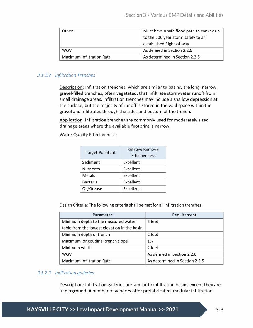
Section 3 > Various BMP Details and Abilities
3 3-3 KAYSVILLE CITY >> Low Impact Development Manual >> 2021
Other Must have a safe flood path to convey up to the 100 year storm safely to an established Right-of-way
WQV As defined in Section 2.2.6 Maximum Infiltration Rate As determined in Section 2.2.5
3.1.2.2 Infiltration Trenches
Description: Infiltration trenches, which are similar to basins, are long, narrow, gravel-filled trenches, often vegetated, that infiltrate stormwater runoff from small drainage areas. Infiltration trenches may include a shallow depression at the surface, but the majority of runoff is stored in the void space within the gravel and infiltrates through the sides and bottom of the trench.
Application: Infiltration trenches are commonly used for moderately sized drainage areas where the available footprint is narrow.
Water Quality Effectiveness:
Target Pollutant Relative Removal
Effectiveness Sediment Excellent Nutrients Excellent Metals Excellent Bacteria Excellent Oil/Grease Excellent
Design Criteria: The following criteria shall be met for all infiltration trenches:
Parameter Requirement Minimum depth to the measured water table from the lowest elevation in the basin
3 feet
Minimum depth of trench 2 feet Maximum longitudinal trench slope 1% Minimum width 2 feet WQV As defined in Section 2.2.6 Maximum Infiltration Rate As determined in Section 2.2.5
3.1.2.3 Infiltration galleries
Description: Infiltration galleries are similar to infiltration basins except they are underground. A number of vendors offer prefabricated, modular infiltration

Section 3 > Various BMP Details and Abilities
4 3-4 KAYSVILLE CITY >> Low Impact Development Manual >> 2021
galleries that provide subsurface storage and allow for infiltration. Infiltration galleries come in a variety of material types, shapes and sizes.
Infiltration galleries are best served when there is an isolator row or pretreatment device. Maintaining underground retention without the isolator row or pretreatment can be problematic and costly.
Application: Infiltration Galleries are typically utilized for drainage areas between 5 and 50 acres.
Water Quality Effectiveness:
Target Pollutant Relative Removal
Effectiveness Sediment Excellent Nutrients Excellent Metals Excellent Bacteria Excellent Oil/Grease Excellent
Design Criteria: The following criteria shall be met for all infiltration galleries:
Parameter Requirement Minimum depth to the measured water table from the lowest elevation in the basin
3 feet
Maximum standing water time 48 hours Other - Must have a safe flood path to
convey up to the 100 year storm safely to an established Right-of-way
- Must meet all the requirements of the manufacturer.
WQV As defined in Section 2.2.6 Maximum Infiltration Rate As determined in Section 2.2.5

Section 3 > Various BMP Details and Abilities
5 3-5 KAYSVILLE CITY >> Low Impact Development Manual >> 2021
3.1.2.4 Injection Wells
Description: An injection well is defined as an excavated, bored, drilled, or driven shaft or hole whose depth is greater than its width. Injection wells are similar to infiltration trenches in their design and function, as they are designed to temporarily store and infiltrate runoff, primarily from rooftops or other impervious areas with low pollutant loading. An injection well may be either a drilled borehole filled with aggregate or a prefabricated storage chamber or pipe segment.
Application: Injection wells are best suited for soils with high conductivity rates. They can contribute to aquifer recharge. As such, they should be registered as Class V Injection Wells with the State Division of Water Quality https://deq.utah.gov/legacy/programs/water-quality/utah-underground-injectioncontrol/drainage-wells/index.htm.
Water Quality Effectiveness:
Target Pollutant Relative Removal
Effectiveness Sediment Excellent Nutrients Excellent Metals Excellent Bacteria Excellent Oil/Grease Excellent
Design Criteria: The following criteria shall be met for all injection wells:
Parameter Requirement Minimum depth to the measured water table from the lowest elevation in the basin
3 feet
Maximum standing water time 48 hours Other - Must have a safe flood path to convey
up to the 100 year storm safely to an established Right-of-way.
- Must meet all the requirements of the manufacturer.
WQV As defined in Section 2.2.6 Maximum Infiltration Rate As determined in Section 2.2.5

Section 3 > Various BMP Details and Abilities
6 3-6 KAYSVILLE CITY >> Low Impact Development Manual >> 2021
3.1.2.5 Constructed Wetlands
Description: A constructed wetland is an artificial wetland created for the purpose of treating discharges such as municipal stormwater runoff. Constructed wetlands are engineered system that use natural functions of vegetation, soil, and organisms to treat water running through them. The wetlands should be designed to spread the flow, slow the velocity and maximize infiltration. The wetlands should also be designed to meet the specific needs of the water running through them including sediment removal, nutrient uptake, and heavy metals containment. Constructed wetlands may also serve a secondary purpose of providing habitat for native or migratory wildlife.
Application: Constructed wetlands can handle unlimited volumes of water provided there is a large enough footprint to process the flows. A good rule of thumb in sizing wetlands is to use 0.5% to 2.0% of the contributing drainage area for the wetland footprint (Tyndall & Bowman, 2016 – A NRS Cost Tool Overview). Constructed wetlands are typically not as effective when they are less than 0.25 acre in size.
Water Quality Effectiveness:
Target Pollutant Relative Removal
Effectiveness Sediment Excellent Nutrients Excellent Metals Excellent Bacteria Excellent Oil/Grease Excellent
Design Criteria: The following criteria shall be met for all constructed wetlands:
Parameter Requirement Maximum depth to the measured water table from the lowest elevation in the wetland
1.5 feet with no supplemental water
Supplemental water To keep a wetland viable it requires a fairly consistent water source. Stormwater, by itself in Utah, does not usually provide adequate water source. It is very likely that supplemental water will be needed.
Hydraulic residence time > 48 hours to achieve 80% reduction in Nitrogen
WQV As defined in Section 2.2.6 Maximum Infiltration Rate As determined in Section 2.2.5

Section 3 > Various BMP Details and Abilities
7 3-7 KAYSVILLE CITY >> Low Impact Development Manual >> 2021
3.1.2.6 Combined Measures
Any of the above infiltration type BMPs may be combined with any other BMPs to fit the site and to meet the allowable discharge requirements.
3.1.3 Natural Filters
Natural Filter facilities are landscaped shallow depressions that capture and filter stormwater runoff. As stormwater passes down through the planting soil, pollutants are filtered, adsorbed, and biodegraded by the soil and plants. Because they are not contained within an impermeable structure, they may allow for some infiltration.
Projects that have demonstrated they cannot manage 100% of the water quality design volume onsite through infiltration may manage the remaining volume through the use of a high removal efficiency natural filter BMP. A high removal efficiency natural filter BMP shall be sized to adequately capture 1.5 times the volume not managed through infiltration and/or capture and use.
3.1.3.1 Biofilter
Description: Most natural filter systems can be classified as biofilters. They normally consist of a ponding area, mulch layer, planting soils, plants, and in some cases an underdrain. Runoff that passes through a biofiltration system is treated by the natural absorption and filtration characteristics of the plants, soils, and microbes with which the water contacts. Plants are used to increase infiltration and nutrient uptake.
Application: Biofilters are typically incorporated into site landscaping elements and are commonly used in park strips and parking lot islands
Water Quality Effectiveness:
Target Pollutant Relative Removal
Effectiveness Sediment Excellent Nutrients Excellent Metals Excellent Bacteria Excellent Oil/Grease Excellent

Section 3 > Various BMP Details and Abilities
8 3-8 KAYSVILLE CITY >> Low Impact Development Manual >> 2021
Design Criteria: The following criteria shall be met for biofilters:
Parameter Requirement Minimum depth to the measured water table from the lowest elevation in the basin
3 feet
Maximum standing water time 48 hours Maximum ponding depth 1 foot WQV As defined in Section 2.3.5 Maximum Infiltration Rate As determined in Section 2.3.4 Minimum freeboard 6 inches Other Must have a safe flood path to convey up
to the 100 year storm safely to an established Right-of-way.
3.1.3.2 Rain Gardens
Description: Rain gardens are simply gardens designed to capture and treat runoff. Rain gardens usually consist of a small depression with engineered or native soils and a variety of plants. The plants are used to increase infiltration and nutrient uptake. They are often topped with wood or rock mulch. For projects with impervious areas exceeding 4,000 square feet; biofilters, planter boxes with infiltration, vegetated swales or natural buffer strips should be considered.
Application: Small sites – impervious areas < 4,000 square feet
Water Quality Effectiveness:
Target Pollutant Relative Removal
Effectiveness Sediment Excellent Nutrients Excellent Metals Excellent Bacteria Excellent Oil/Grease Excellent

Section 3 > Various BMP Details and Abilities
9 3-9 KAYSVILLE CITY >> Low Impact Development Manual >> 2021
Design Criteria: The following criteria shall be met for rain gardens:
Parameter Requirement Minimum depth to the measured water table from the lowest elevation in the basin
3 feet
Maximum standing water time 48 hours Maximum ponding depth 18 inches Maximum side slopes 3H:1V Minimum freeboard 6 inches Other Must have a safe flood path to convey up
to the 100 year storm safely to an established Right-of-way.
WQV As defined in Section 2.2.6 Maximum Infiltration Rate As determined in Section 2.2.5
3.1.3.3 Planter Boxes with infiltration
Description: Planter boxes with infiltration are natural filtration treatment control measures located in and around structures and facilities to handle larger volumes of water than a typical rain garden. They typically are constructed with vertical or near vertical sides and above ground. They can be equipped with underdrains if necessary. Planter boxes with infiltration should maintain setbacks from adjacent buildings, other structures, sidewalks or roadways.
Application: Planter boxes with infiltration are typically incorporated into site landscaping elements and are commonly used in park strips and parking lot islands. They are sometimes raised planters. Raised planters are most successful for treating stormwater from roof tops.
Water Quality Effectiveness:
Target Pollutant Relative Removal
Effectiveness Sediment Excellent Nutrients Excellent Metals Excellent Bacteria Excellent Oil/Grease Excellent

Section 3 > Various BMP Details and Abilities
10 3-10 KAYSVILLE CITY >> Low Impact Development Manual >> 2021
Design Criteria: The following criteria shall be met for planter boxes with infiltration:
Parameter Requirement Minimum depth to the measured water table from the lowest elevation in the basin
3 feet
Maximum standing water time 48 hours Maximum ponding depth 1 foot WQV As defined in Section 2.3.5 Maximum Infiltration Rate As determined in Section 2.3.4 Minimum freeboard 6 inches Other Must have a safe flood path to convey up
to the 100 year storm safely to an established Right-of-way.
3.1.3.4 Bio-Infiltration
Description: Bioinfiltration facilities are designed for partial infiltration of runoff and partial biotreatment. These facilities are similar to bioretention devices with underdrains but they include a raised underdrain above a gravel sump designed to facilitate infiltration and nitrification/denitrification. These facilities can be used in areas where there are little to no hazards associated with infiltration, but infiltration screening does not allow for infiltration BMPs due to low infiltration rates or high depths of fill.
Application: Bio-infiltration systems are typically incorporated into site landscaping elements and are commonly used in park strips and parking lot islands. Bio-infiltration includes a higher likelihood for infiltration than the basic biofilter.
Water Quality Effectiveness:
Target Pollutant Relative Removal
Effectiveness Sediment Excellent Nutrients Excellent Metals Excellent Bacteria Excellent Oil/Grease Excellent

Section 3 > Various BMP Details and Abilities
11 3-11 KAYSVILLE CITY >> Low Impact Development Manual >> 2021
Design Criteria: The following criteria shall be met for bio-infiltration:
Parameter Requirement Minimum depth to the measured water table from the lowest elevation in the basin
3 feet
Maximum standing water time 48 hours Maximum ponding depth 1 foot WQV As defined in Section 2.3.5 Maximum Infiltration Rate As determined in Section 2.3.4 Minimum freeboard 6 inches Other Must have a safe flood path to convey up
to the 100 year storm safely to an established Right-of-way.
3.1.3.5 Vegetated Swales
Description: Vegetated swales are open, shallow channels with dense, low-lying vegetation covering the side slopes and bottom that collect and slowly convey runoff to downstream discharge points. An effective vegetated swale achieves uniform sheet flow through the densely vegetated area for a period of several minutes. The vegetation in the swale can vary depending on its location and is the choice of the designer. Most swales are grass-lined.
Application: Vegetated swales serve a dual function. They are used both as a minor treatment alternative and as a conveyance system.
Water Quality Effectiveness:
Target Pollutant Relative Removal
Effectiveness Sediment Good Nutrients Fair Metals Good Bacteria Fair Oil/Grease Excellent
Design Criteria: The following criteria shall be met for vegetated swales:
Parameter Requirement Minimum depth to the measured water table from the lowest elevation in the basin
3 feet

Section 3 > Various BMP Details and Abilities
12 3-12 KAYSVILLE CITY >> Low Impact Development Manual >> 2021
Maximum longitudinal slope 5% Maximum side slope 3H:1V Maximum velocity 1.0 ft/s Maximum flow depth 2/3 vegetation height WQV As defined in Section 2.3.5 Minimum freeboard 6 inches Maximum Infiltration Rate As determined in Section 2.3.4 Minimum residence time 5. min Vegetative Cover >65%
3.1.3.6 Filter or buffer strips
Description: Filter strips are vegetated areas designed to treat sheet flow runoff from adjacent impervious surfaces such as parking lots and roadways, or intensive landscaped areas such as golf courses. While some assimilation of dissolved constituents may occur, filter strips are generally more effective in trapping sediment and particulate-bound metals, nutrients, and pesticides. Filter strips are more effective when the runoff passes through the vegetation and thatch layer in the form of shallow, uniform flow. Filter strips are primarily used to pretreat runoff before it flows to an infiltration BMP or another natural filtration BMP.
Application: Most effective when inflow is not concentrated, but comes in by sheet flow. Works well on road shoulders or off parking lots with no curb and gutter.
Water Quality Effectiveness:
Target Pollutant Relative Removal
Effectiveness Sediment Good Nutrients Fair Metals Good Bacteria Excellent Oil/Grease Excellent
Design Criteria: The following criteria shall be met for filter or buffer strips:
Parameter Requirement Minimum flow length 15 feet Maximum longitudinal slope 5H:1V Maximum flow velocity 1.0 ft/s Maximum flow depth 2/3 vegetation height Minimum freeboard 6 inches

Section 3 > Various BMP Details and Abilities
13 3-13 KAYSVILLE CITY >> Low Impact Development Manual >> 2021
Minimum vegetation cover >65% WQV As defined in Section 2.2.6 Maximum Infiltration Rate As determined in Section 2.2.5
3.1.3.7 Velocity Dissipaters
Description: Velocity dissipaters are BMPs designed to slow the velocity and minimize erosive action of flowing water. Check dams and level spreaders are two kinds of velocity dissipaters that are commonly used. Check dams are designed to create a series of step-downs with pools in between while level spreaders are designed like weirs to spread the flow out and to control water levels. Level spreaders are commonly used in wetland areas to maintain a uniform distribution of water and keep the flows from channelizing.
Application: Typically used in flow channels (concentrated flows) or to disperse water entering into a wetland area
Water Quality Effectiveness:
Target Pollutant Relative Removal
Effectiveness Sediment Good Nutrients Fair Metals Fair Bacteria Good Oil/Grease Fair
Design Criteria: The following criteria shall be met for velocity dissipaters:
Parameter Requirement Maximum flow velocity 1.0 f/s Minimum freeboard 6 inches WQV As defined in Section 2.2.6 Maximum Infiltration Rate As determined in Section 2.2.5

Section 3 > Various BMP Details and Abilities
14 3-14 KAYSVILLE CITY >> Low Impact Development Manual >> 2021
3.1.4 Man-made Treatment
3.1.4.1 Hydrodynamic Separators
Description: Hydrodynamic separators are stormwater management devices that work primarily based on vortex and gravity principles to separate stormwater from the pollutants. They are generally designed as flow-through systems with either on-line or off-line storage of pollutants. They include chambers for settling and storage of pollutants and are often used in conjunction with other BMPs as pretreatment. They are not especially effective for the removal of fine materials or dissolved pollutants. On-line separators are more susceptible to scour or re-suspension of pollutants than systems that incorporate off-line storage. They are generally not designed to treat stormwater flows exceeding 25 cfs.
Application: Typically limited by flow rates. Small footprint, but normally require depth for pollutant storage
Water Quality Effectiveness:
Target Pollutant Relative Removal
Effectiveness Sediment Excellent Nutrients Good Metals Excellent Bacteria Fair Oil/Grease Good
Design Criteria: The following criteria shall be met for hydrodynamic separators:
Parameter Requirement Maximum flow rate for prefabricated units 25 cfs Design per manufacturer’s requirements Typically need a high flow bypass WQV As defined in Section 2.2.6
3.1.4.2 Safl Baffle
Description: Safl Baffles are a brand name product designed primarily as a post-construction retrofit pretreatment system. They require a sump structure. A specially designed perforated metal plate is installed inside a sump manhole or vault. Water flows through the plate. This action facilitates improved settling and re-suspension characteristics. Sediment removal rates are generally less than with hydrodynamic separators. These baffles are a fair low cost alternative that require a minimal footprint.

Section 3 > Various BMP Details and Abilities
15 3-15 KAYSVILLE CITY >> Low Impact Development Manual >> 2021
Sediments are stored in the lower reaches of the manhole or vault. Safl Baffles are not effective for floatables.
Application: Typically can be used anywhere a hydrodynamic separator can be used, but can handle higher flow rates. Pollutant removal rates slightly worse than a hydrodynamic separator.
Water Quality Effectiveness:
Target Pollutant Relative Removal
Effectiveness Sediment Good Nutrients Fair Metals Good Bacteria Fair Oil/Grease Poor*
*When used in conjunction with a skimmer their performance with oil/grease is “Good”
Design Criteria: The following criteria shall be met for Safl Baffles:
Parameter Requirement Maximum flow rate 50 cfs Design per manufacturer’s requirements Removal efficiency goes down with higher flows WQV As defined in Section 2.2.6
3.1.4.3 Skimmer
Description: Skimmers are designed to trap floatables in a holding facility until they can be removed by absorbent materials or a vactor truck. They can take many shapes and sizes. They can be prefabricated or custom built to fit the needs of almost any project. They generally require a certain amount of standing water to maintain a seal so the floatables cannot escape. They also require relatively frequent inspection and maintenance because of small storage capacity. They work on the principle of baffles
Application: Skimmers are typically not used as standalone treatment options. They are best utilized when floatables are the primary pollutant of concern

Section 3 > Various BMP Details and Abilities
16 3-16 KAYSVILLE CITY >> Low Impact Development Manual >> 2021
Water Quality Effectiveness:
Target Pollutant Relative Removal
Effectiveness Sediment Poor Nutrients Poor Metals Poor Bacteria Poor Oil/Grease Good
Design Criteria:
Per Manufacturer’s recommendations
3.2 Sample Calculations
All categories of BMPs require a determination of the Water Quality Volume (WQV). Section 2.2.6 describes that calculation process.
3.2.1 Calculating Size Requirements for Infiltration BMPs
The main challenge associated with infiltration BMPs is preventing system clogging and subsequent infiltration inhibition. In addition, infiltration BMPs must be designed to drain in a reasonable period of time so that storage capacity is available for subsequent storms and so that standing water does not result in unwanted conditions. Infiltration BMPs should be designed according to the requirements listed in Table 3-1 and outlined in the following text:
Infiltration facilities must be sized to completely infiltrate the design capture volume within 72 hours.
Step 1: Calculate the Design Volume
Infiltration facilities shall be sized to capture and infiltrate the water quality volume as described in section 2.2.6.
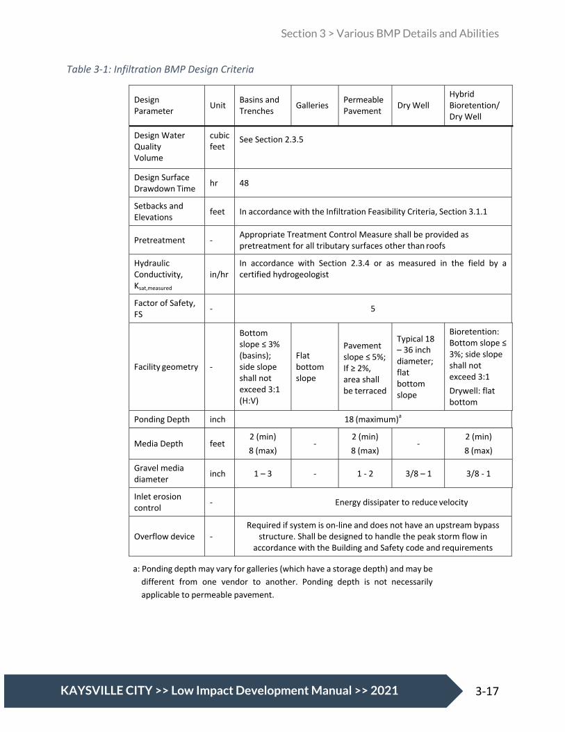
Section 3 > Various BMP Details and Abilities
17 3-17 KAYSVILLE CITY >> Low Impact Development Manual >> 2021
Table 3-1: Infiltration BMP Design Criteria
Design Parameter
Unit
Basins and Trenches
Galleries
Permeable Pavement
Dry Well
Hybrid Bioretention/ Dry Well
Design Water Quality Volume
cubic feet
See Section 2.3.5
Design Surface Drawdown Time
hr
48
Setbacks and Elevations
feet
In accordance with the Infiltration Feasibility Criteria, Section 3.1.1
Pretreatment
- Appropriate Treatment Control Measure shall be provided as
pretreatment for all tributary surfaces other than roofs
Hydraulic Conductivity, Ksat,measured
in/hr
In accordance with Section 2.3.4 or as measured in the field by a certified hydrogeologist
Factor of Safety, FS
-
5
Facility geometry
-
Bottom slope ≤ 3% (basins); side slope shall not exceed 3:1 (H:V)
Flat bottom slope
Pavement slope ≤ 5%; If ≥ 2%, area shall be terraced
Typical 18 – 36 inch diameter; flat bottom slope
Bioretention: Bottom slope ≤ 3%; side slope shall not exceed 3:1 Drywell: flat bottom
Ponding Depth inch 18 (maximum)a
Media Depth
feet
2 (min) 8 (max)
-
2 (min) 8 (max)
-
2 (min) 8 (max)
Gravel media diameter
inch
1 – 3
-
1 - 2
3/8 – 1
3/8 - 1
Inlet erosion control
-
Energy dissipater to reduce velocity
Overflow device
-
Required if system is on-line and does not have an upstream bypass structure. Shall be designed to handle the peak storm flow in
accordance with the Building and Safety code and requirements
a: Ponding depth may vary for galleries (which have a storage depth) and may be different from one vendor to another. Ponding depth is not necessarily applicable to permeable pavement.
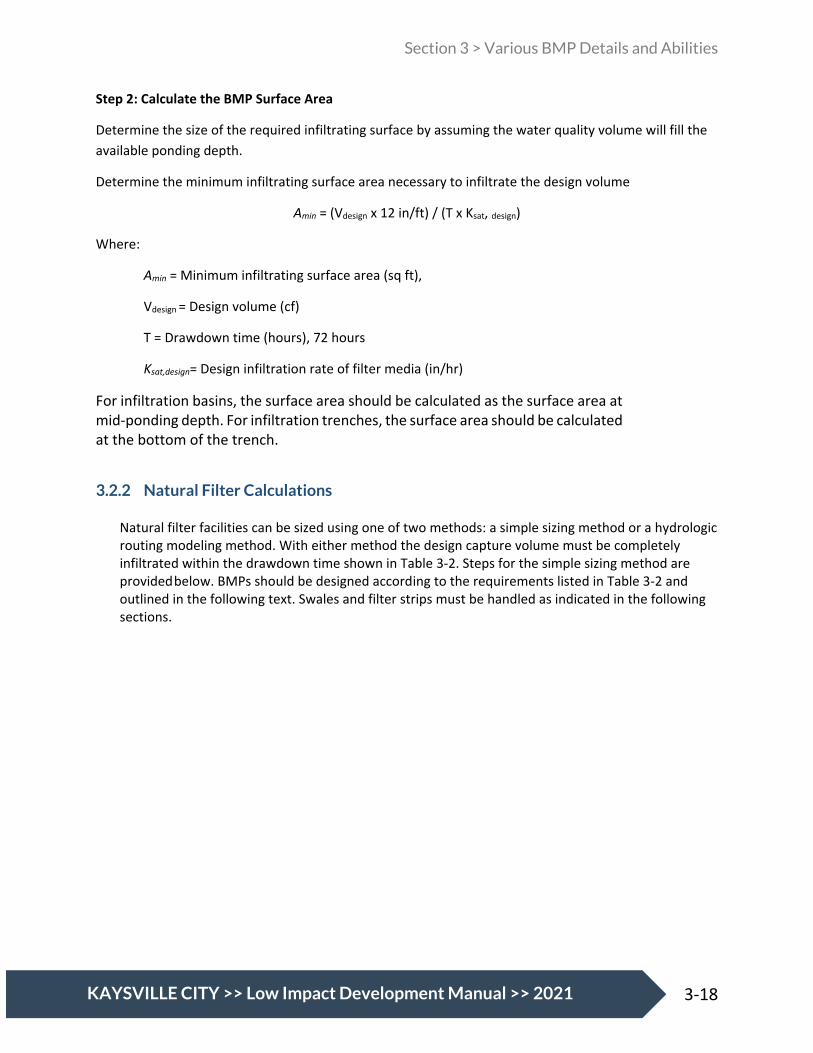
Section 3 > Various BMP Details and Abilities
18 3-18 KAYSVILLE CITY >> Low Impact Development Manual >> 2021
Step 2: Calculate the BMP Surface Area
Determine the size of the required infiltrating surface by assuming the water quality volume will fill the available ponding depth.
Determine the minimum infiltrating surface area necessary to infiltrate the design volume
Amin = (Vdesign x 12 in/ft) / (T x Ksat, design)
Where:
Amin = Minimum infiltrating surface area (sq ft),
Vdesign = Design volume (cf)
T = Drawdown time (hours), 72 hours
Ksat,design= Design infiltration rate of filter media (in/hr)
For infiltration basins, the surface area should be calculated as the surface area at mid-ponding depth. For infiltration trenches, the surface area should be calculated at the bottom of the trench.
3.2.2 Natural Filter Calculations
Natural filter facilities can be sized using one of two methods: a simple sizing method or a hydrologic routing modeling method. With either method the design capture volume must be completely infiltrated within the drawdown time shown in Table 3-2. Steps for the simple sizing method are provided below. BMPs should be designed according to the requirements listed in Table 3-2 and outlined in the following text. Swales and filter strips must be handled as indicated in the following sections.
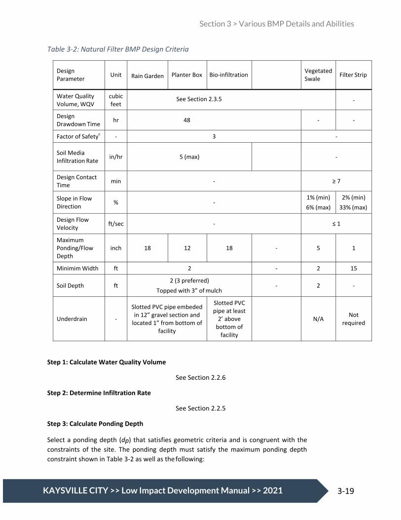
Section 3 > Various BMP Details and Abilities
19 3-19 KAYSVILLE CITY >> Low Impact Development Manual >> 2021
Table 3-2: Natural Filter BMP Design Criteria
Design Parameter
Unit Rain Garden
Planter Box
Bio-infiltration
Vegetated Swale
Filter Strip
Water Quality Volume, WQV
cubic feet
See Section 2.3.5
-
Design Drawdown Time
hr
48
-
-
Factor of Safetyc - 3 -
Soil Media Infiltration Rate
in/hr
5 (max)
-
Design Contact Time
min
-
≥ 7
Slope in Flow Direction
%
-
1% (min) 6% (max)
2% (min) 33% (max)
Design Flow Velocity
ft/sec
-
≤ 1
Maximum Ponding/Flow Depth
inch
18
12
18
-
5
1
Minimim Width ft 2 - 2 15
Soil Depth
ft 2 (3 preferred)
Topped with 3” of mulch
-
2
-
Underdrain
-
Slotted PVC pipe embeded in 12” gravel section and
located 1” from bottom of facility
Slotted PVC pipe at least
2’ above bottom of
facility
N/A
Not required
Step 1: Calculate Water Quality Volume
See Section 2.2.6
Step 2: Determine Infiltration Rate
See Section 2.2.5
Step 3: Calculate Ponding Depth
Select a ponding depth (dp) that satisfies geometric criteria and is congruent with the constraints of the site. The ponding depth must satisfy the maximum ponding depth constraint shown in Table 3-2 as well as the following:

Section 3 > Various BMP Details and Abilities
20 3-20 KAYSVILLE CITY >> Low Impact Development Manual >> 2021
dp (ft) = (Ksat,design x T) / 12
Where: dp = Ponding depth (ft)
Ksat,design= Design infiltration rate of filter media (in/hr)
T = Required surface drain time (hrs), from Table 4.2
Step 4: Calculate Surface Area
Amin = (Vdesign) / [(Tfill x Ksat/12)+ d]
Where:
Amin = Design infiltrating area (sq ft)
Tfill= Time to fill to max ponding depth with water (hrs) [unless a hydrologic routing model is used, assume a maximum of 3 hours]
Ksat,= Design infiltration rate of filter media (in/hr)
d = depth of ponded water (ft)
The calculated BMP surface area only considers the surface area of the BMP where infiltration through amended media can occur. The total footprint of the BMP should include a buffer for side slopes and freeboard.
3.2.3 Swale Sizing
Swales shall be designed with a trapezoidal channel shape with side slopes of 3:1 (H:V). They shall incorporate at least two feet of soil beneath the vegetated surface. Swale sizing will be determined on a case-by-case basis. As is the case with other biofiltration BMPs, the sizing criteria presented in Table 3-2 must be met.
3.2.4 Filter Strip Sizing
Because filter strips are most often used for pretreatment purposes, their design will depend on the desired flow-rate to be treated and the type of BMP downstream, among other factors. As a result, filter strip sizing is not covered in this manual, but will be determined on a case-by-case basis.

Section 4 > Offsite Mitigation Measures
1 4-1 KAYSVILLE CITY >> Low Impact Development Manual >> 2021
4. Offsite Mitigation Measures 4.1 Offsite Mitigation Measures
Offsite mitigation shall only be utilized after on-site mitigation opportunities are exhausted and after approval from the City. If on-site mitigation meets the minimum requirements no off-site mitigation will be required. The following criteria shall be implemented in considering off-site mitigation:
1. Locate off-site projects as close as possible to the project site. 2. Locate off-site projects within the same sub-watershed as the proposed project. 3. Off-site projects may be completed on either private or public land. 4. Secure needed easements and rights to the property on which off-site projects are completed. 5. Demonstrate that same level of water quality protection is achieved as if all the runoff were
retained on-site. 6. Demonstrate that the off-site project, including any on-site mitigation, addresses the same
volume of water that would have been addressed if BMPs were all constructed on-site. 7. The developer shall execute an Agreement in Perpetuity with the city and recorded with the
property, for on-going maintenance and upkeep of both on-site and off-site BMP(s).
4.2 Regional Facilities
In lieu of an independent off-site mitigation project designed specifically to meet the needs of a given project, the developer may be able to work together with the City and/or other groups to construct a larger regional water quality mitigation project. If a regional project is pursued, the following criteria should be considered:
1. An agreement shall be obtained with the City and/or other partners for the design, sizing, construction and maintenance of the regional facility.
2. The regional facility shall be sized to accommodate the water quality needs of all interested parties.
3. The same net level of water quality protection shall be achieved for the combined facility as would be required for each separate entity as if they were separate and distinct facilities.
4. The same total volume of water required to be addressed at each individual and independent site shall be addressed as the accumulated total volume at the regional facility.
5. All Maintenance Agreements in Perpetuity that would have been required for each separate facility shall be addressed in agreement(s) for the regional facility and shall be recorded with each parcel encompassed as part of the regional facility.

Kaysville LID Manual >> 2021
WATER QUALITY VOLUME REPORT FORM
APPENDIX A

Appendix A: Water Quality Volume Report Form
Kaysville LID Manual >> 2021
Water Quality Volume Report Form
PRACTICES HANDBOOK – P

Kaysville LID Manual >> 2021
B: PLANNING ACTIVITIES, 4TH ED. STORM WATER QUALITY REPORT
Date: _____________________________ Project Name: _____________________________ Project ID: _____________________________ Design Engineer: _____________________________
Is the project within a watershed that is 303(d) listed? (http://mapserv.utah.gov/surfacewaterquality/)
If yes:
Name of Receiving Water(s): ________________________________________
Listed Impairment(s): _______________________________________________
Does the watershed have an approved TMDL?
If yes:
Approved TMDL(s): _______________________________________________
I have reviewed the storm water quality design and find this report to be complete, accurate, and current.
_________________________________________________ (Name), Project Manager
_________________________________________________ (Name), Permittee’s Designated Storm Water Coordinator
_________________________________________________
(PE stamp required) (Name), Permittee’s Head of Maintenance

Kaysville LID Manual >> 2021
Project Information
Type of Project (New Development, Redevelopment): _________________________________________
Area of Land Disturbance (acre): _______________________
Project Impervious Area (acre): ____________________
Project Imperviousness (%): _____________________
Project Runoff Coefficient, Rv: ______________________
90th Percentile Storm Depth (in): ______________________
Project 90th Percentile Volume, Vgoal(cf): ____________________
Groundwater Information
Depth to Groundwater (ft): ____________________________
Historical High Depth to Groundwater, if known (ft): ______________________
Source: ___________________________
Soil Information
Infiltration Rate (in/hr): _____________________________
Source: _________________________________
LID Drainage Areas
(add additional rows as needed)
Contributing Drainage Area Area (acre) Impervious
Area (acre) Imperviousness
(%) Runoff
Coefficient, Rv
Water Quality Volume WQV (cf)
Total WQV (cf)

Kaysville LID Manual >> 2021
LID BMP Design
(add additional rows as needed)
Contributing Drainage Area LID BMP Type Water Quality
Volume WQV (cf) Runoff
Retained (cf) Percent of Runoff
Captured (%)
Total Volume Retained (cf)
Percent of Vgoal captured by LID BMPs: _______%
If 100% of Vgpal is not captured, document and provide narrative of technical infeasibilities and/or alternate compliance measures below:
_____________________________________________________________________________________
_____________________________________________________________________________________
_____________________________________________________________________________________
_____________________________________________________________________________________
Describe additional storm water quality measures incorporated into the site:
_____________________________________________________________________________________
_____________________________________________________________________________________
_____________________________________________________________________________________
_____________________________________________________________________________________

Kaysville LID Manual >> 2021
80TH PERCENTILE STORM EVENT CALCULATION
APPENDIX B

Appendix B: 80th Percentile Storm Event Calculations
Kaysville LID Manual >> 2021
Weber Basin
Fruit Heights
Ogden Hinkley Airport
Farmington Lower
Triad Center
Salt Lake International Airport
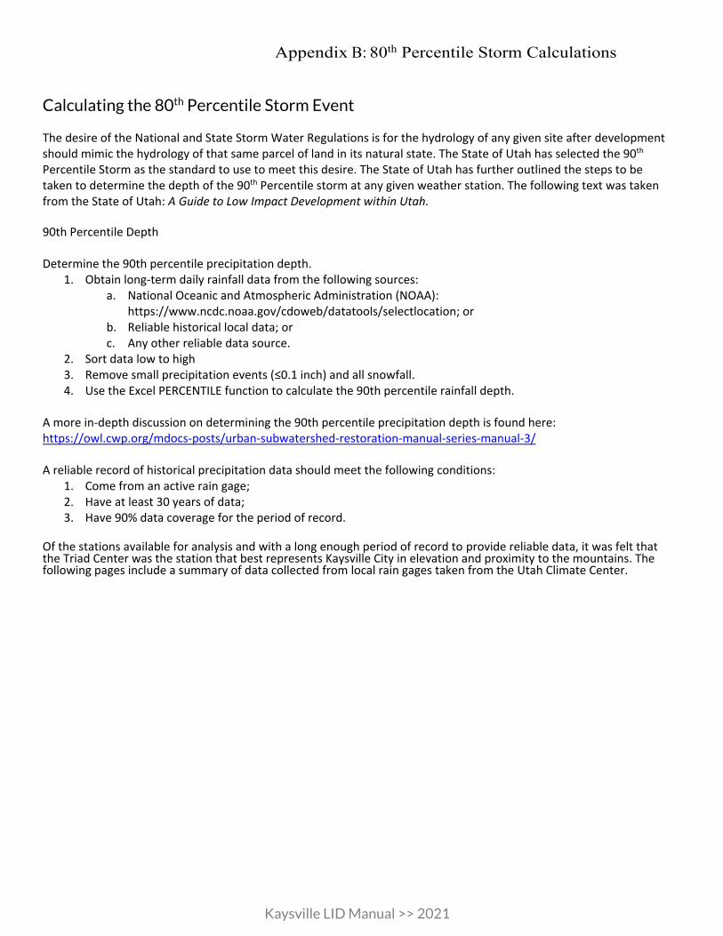
Appendix B: 80th Percentile Storm Calculations
Kaysville LID Manual >> 2021
Calculating the 80th Percentile Storm Event
The desire of the National and State Storm Water Regulations is for the hydrology of any given site after development should mimic the hydrology of that same parcel of land in its natural state. The State of Utah has selected the 90th Percentile Storm as the standard to use to meet this desire. The State of Utah has further outlined the steps to be taken to determine the depth of the 90th Percentile storm at any given weather station. The following text was taken from the State of Utah: A Guide to Low Impact Development within Utah. 90th Percentile Depth Determine the 90th percentile precipitation depth.
1. Obtain long-term daily rainfall data from the following sources: a. National Oceanic and Atmospheric Administration (NOAA):
https://www.ncdc.noaa.gov/cdoweb/datatools/selectlocation; or b. Reliable historical local data; or c. Any other reliable data source.
2. Sort data low to high 3. Remove small precipitation events (≤0.1 inch) and all snowfall. 4. Use the Excel PERCENTILE function to calculate the 90th percentile rainfall depth.
A more in-depth discussion on determining the 90th percentile precipitation depth is found here: https://owl.cwp.org/mdocs-posts/urban-subwatershed-restoration-manual-series-manual-3/ A reliable record of historical precipitation data should meet the following conditions:
1. Come from an active rain gage; 2. Have at least 30 years of data; 3. Have 90% data coverage for the period of record.
Of the stations available for analysis and with a long enough period of record to provide reliable data, it was felt that the Triad Center was the station that best represents Kaysville City in elevation and proximity to the mountains. The following pages include a summary of data collected from local rain gages taken from the Utah Climate Center.
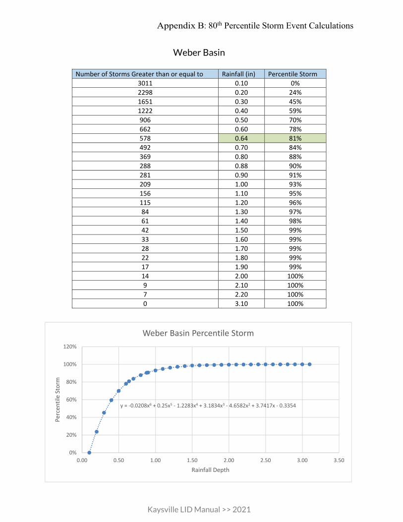
Appendix B: 80th Percentile Storm Event Calculations
Kaysville LID Manual >> 2021
Weber Basin
PRACTICES HANDBOOK – Part B: PLANNING ACTIVITIES,
Number of Storms Greater than or equal to Rainfall (in) Percentile Storm 3011 0.10 0% 2298 0.20 24% 1651 0.30 45% 1222 0.40 59% 906 0.50 70% 662 0.60 78% 578 0.64 81% 492 0.70 84% 369 0.80 88% 288 0.88 90% 281 0.90 91% 209 1.00 93% 156 1.10 95% 115 1.20 96% 84 1.30 97% 61 1.40 98% 42 1.50 99% 33 1.60 99% 28 1.70 99% 22 1.80 99% 17 1.90 99% 14 2.00 100% 9 2.10 100% 7 2.20 100% 0 3.10 100%
y = -0.0208x6 + 0.25x5 - 1.2283x4 + 3.1834x3 - 4.6582x2 + 3.7417x - 0.3354
0%
20%
40%
60%
80%
100%
120%
0.00 0.50 1.00 1.50 2.00 2.50 3.00 3.50
Perc
entil
e St
orm
Rainfall Depth
Weber Basin Percentile Storm

Appendix B: 80th Percentile Storm Calculations
Kaysville LID Manual >> 2021
ED. Fruit Heights
Number of Storms Greater than or equal to Rainfall (in) Percentile Storm 324 0.10 0% 248 0.20 23% 190 0.30 41% 134 0.40 59% 103 0.50 68% 78 0.60 76% 68 0.64 79% 52 0.70 84% 41 0.80 87% 32 0.86 90% 28 0.90 91% 20 1.00 94% 12 1.10 96% 9 1.30 97% 6 1.40 98% 4 1.60 99% 1 2.20 100% 0 2.80 100%
y = -0.0098x6 + 0.1289x5 - 0.7159x4 + 2.1398x3 - 3.6301x2 + 3.325x - 0.2997
-20%
0%
20%
40%
60%
80%
100%
120%
0.00 0.50 1.00 1.50 2.00 2.50 3.00 3.50
Perc
entil
e St
orm
Rainfall Depth
Fruit Heights Percentile Storm
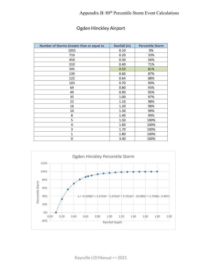
Appendix B: 80th Percentile Storm Event Calculations
Kaysville LID Manual >> 2021
Ogden Hinckley Airport
Number of Storms Greater than or equal to Rainfall (in) Percentile Storm 1055 0.10 0% 710 0.20 33% 459 0.30 56% 310 0.40 71% 205 0.50 81% 139 0.60 87% 122 0.64 88% 103 0.70 90% 69 0.80 93% 49 0.90 95% 35 1.00 97% 22 1.10 98% 16 1.20 98% 10 1.30 99% 8 1.40 99% 5 1.50 100% 4 1.60 100% 3 1.70 100% 1 1.80 100% 0 3.40 100%
y = -0.1668x6 + 1.4734x5 - 5.2354x4 + 9.7016x3 - 10.089x2 + 5.7698x - 0.4871
-20%
0%
20%
40%
60%
80%
100%
120%
0.00 0.20 0.40 0.60 0.80 1.00 1.20 1.40 1.60 1.80 2.00
Perc
entil
e St
orm
Rainfall Depth
Ogden Hinckley Percentile Storm

Appendix B: 80th Percentile Storm Calculations
Kaysville LID Manual >> 2021
Farmington Lower
Number of Storms Greater than or equal to Rainfall (in) Percentile Storm 518 0.10 0% 343 0.20 34% 237 0.30 54% 159 0.40 69% 105 0.50 80% 71 0.60 86% 65 0.64 87% 52 0.70 90% 37 0.80 93% 20 0.90 96% 14 1.00 97% 10 1.10 98% 5 1.20 99% 4 1.30 99% 3 1.40 99% 3 1.50 99% 2 1.60 100% 2 1.70 100% 0 1.80 100%
y = -0.3248x6 + 2.3808x5 - 7.1631x4 + 11.512x3 - 10.755x2 + 5.8043x - 0.4817
0%
20%
40%
60%
80%
100%
120%
0.00 0.20 0.40 0.60 0.80 1.00 1.20 1.40 1.60 1.80 2.00
Perc
entil
e St
orm
Rainfall Depth
Farmington Lower Percentile Storm

Appendix B: 80th Percentile Storm Event Calculations
Kaysville LID Manual >> 2021
Triad Center
Number of Storms Greater than or equal to Rainfall (in) Percentile Storm 1286 0.10 0% 831 0.20 35% 547 0.30 58% 369 0.40 71% 238 0.48 80% 164 0.60 87% 132 0.65 90% 108 0.70 92% 75 0.80 94% 46 0.90 96% 33 1.00 97% 20 1.10 98% 15 1.20 99% 8 1.30 99% 7 1.40 99% 4 1.50 100% 3 1.60 100% 1 1.70 100% 1 1.80 100% 0 1.90 100%
y = -0.2246x6 + 1.8514x5 - 6.212x4 + 10.954x3 - 10.906x2 + 6.0086x - 0.4981R² = 0.9998
0%
20%
40%
60%
80%
100%
120%
0.00 0.50 1.00 1.50 2.00 2.50
Perc
entil
e St
orm
Rainfall Depth (in)
Triad Percentile Storm
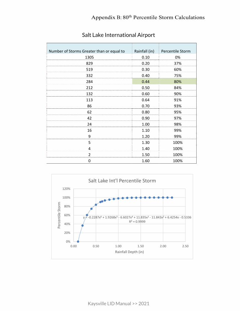
Appendix B: 80th Percentile Storm Calculations
Kaysville LID Manual >> 2021
Salt Lake International Airport
Number of Storms Greater than or equal to Rainfall (in) Percentile Storm
1305 0.10 0% 829 0.20 37% 519 0.30 60% 332 0.40 75% 284 0.44 80% 212 0.50 84% 132 0.60 90% 113 0.64 91% 86 0.70 93% 62 0.80 95% 42 0.90 97% 24 1.00 98% 16 1.10 99% 9 1.20 99% 5 1.30 100% 4 1.40 100% 2 1.50 100% 0 1.60 100%
y = -0.2287x6 + 1.9268x5 - 6.6027x4 + 11.835x3 - 11.843x2 + 6.4254x - 0.5336R² = 0.9999
0%
20%
40%
60%
80%
100%
120%
0.00 0.50 1.00 1.50 2.00 2.50
Perc
entil
e St
orm
Rainfall Depth (in)
Salt Lake Int'l Percentile Storm

Kaysville LID Manual >> 2021
MUNICIPAL ORDINANCES
APPENDIX C

Appendix C: Municipal Ordinances
Title 9 – Public Works
Chapter 3 ....................................................................................................... Storm Water
Chapter 3a ................................................................................ Storm Drainage System
Chapter 3b.................................................. Storm Water Management and Permit
Chapter 3c .......................................................................................... Prohibited Actions
Chapter 3d....................................................................... Violations and Enforcement
Title 18 – Building Regulations
Chapter 1 ............................................................................................. General Provisions
Chapter 2 .................................................................................................... Standard Codes
Chapter 3 ................................................................................. Residential Construction
Chapter 4 ...................... Commercial, Industrial, and Institutional Development
Chapter 5 ........................................................................... Commercial Building Design
Title 19 – Subdivision
Chapter 1 ........................................................................................... General Provisions
Chapter 2 .............................................................................. Development Procedures
Chapter 3 ................................................................................................. Preliminary Plat
Chapter 4 ............................................................................................................... Final Plat
Chapter 5 ..................................................................................... Subdivision Standards
Chapter 6 ........................................................ Subdivision Improvements Required
Chapter 7 ........................................................................................................................ Fees
PRACTICES HANDBOOK – Part B: PLANNING ACTIVITIES, 4TH ED.