Coulon, Pierre Marie and Kusch, Gunnar and Fletcher ... · an NH3 flow rate of 4000 sccm (V/III...
13
Coulon, Pierre Marie and Kusch, Gunnar and Fletcher, Philip and Chausse, Pierre and Martin, Robert W. and Shields, Philip A. (2018) Hybrid top-down/bottom-up fabrication of a highly uniform and organized faceted AlN nanorod scaffold. Materials, 11 (7). ISSN 1996- 1944 , http://dx.doi.org/10.3390/ma11071140 This version is available at https://strathprints.strath.ac.uk/64810/ Strathprints is designed to allow users to access the research output of the University of Strathclyde. Unless otherwise explicitly stated on the manuscript, Copyright © and Moral Rights for the papers on this site are retained by the individual authors and/or other copyright owners. Please check the manuscript for details of any other licences that may have been applied. You may not engage in further distribution of the material for any profitmaking activities or any commercial gain. You may freely distribute both the url ( https://strathprints.strath.ac.uk/ ) and the content of this paper for research or private study, educational, or not-for-profit purposes without prior permission or charge. Any correspondence concerning this service should be sent to the Strathprints administrator: [email protected] The Strathprints institutional repository (https://strathprints.strath.ac.uk ) is a digital archive of University of Strathclyde research outputs. It has been developed to disseminate open access research outputs, expose data about those outputs, and enable the management and persistent access to Strathclyde's intellectual output.
Transcript of Coulon, Pierre Marie and Kusch, Gunnar and Fletcher ... · an NH3 flow rate of 4000 sccm (V/III...

Coulon, Pierre Marie and Kusch, Gunnar and Fletcher, Philip and
Chausse, Pierre and Martin, Robert W. and Shields, Philip A. (2018)
Hybrid top-down/bottom-up fabrication of a highly uniform and
organized faceted AlN nanorod scaffold. Materials, 11 (7). ISSN 1996-
1944 , http://dx.doi.org/10.3390/ma11071140
This version is available at https://strathprints.strath.ac.uk/64810/
Strathprints is designed to allow users to access the research output of the University of
Strathclyde. Unless otherwise explicitly stated on the manuscript, Copyright © and Moral Rights
for the papers on this site are retained by the individual authors and/or other copyright owners.
Please check the manuscript for details of any other licences that may have been applied. You
may not engage in further distribution of the material for any profitmaking activities or any
commercial gain. You may freely distribute both the url (https://strathprints.strath.ac.uk/) and the
content of this paper for research or private study, educational, or not-for-profit purposes without
prior permission or charge.
Any correspondence concerning this service should be sent to the Strathprints administrator:
The Strathprints institutional repository (https://strathprints.strath.ac.uk) is a digital archive of University of Strathclyde research
outputs. It has been developed to disseminate open access research outputs, expose data about those outputs, and enable the
management and persistent access to Strathclyde's intellectual output.

materials
Article
Hybrid Top-Down/Bottom-Up Fabrication of a HighlyUniform and Organized Faceted AlNNanorod Scaffold
Pierre-Marie Coulon 1,*, Gunnar Kusch 2, Philip Fletcher 1 ID , Pierre Chausse 1,
Robert W. Martin 2 ID and Philip A. Shields 1 ID
1 Centre of Nanoscience & Nanotechnology & Department of Electronic and Electrical Engineering,University of Bath, Bath BA2 7AY, UK; [email protected] (P.F.); [email protected] (P.C.);[email protected] (P.A.S.)
2 Department of Physics, SUPA, University of Strathclyde, Glasgow G4 0NG, UK;[email protected] (G.K.); [email protected] (R.W.M.)
* Correspondence: [email protected]
Received: 12 June 2018; Accepted: 2 July 2018; Published: 5 July 2018�����������������
Abstract: As a route to the formation of regular arrays of AlN nanorods, in contrast to other III-Vmaterials, the use of selective area growth via metal organic vapor phase epitaxy (MOVPE) has sofar not been successful. Therefore, in this work we report the fabrication of a highly uniform andordered AlN nanorod scaffold using an alternative hybrid top-down etching and bottom-up regrowthapproach. The nanorods are created across a full 2-inch AlN template by combining DisplacementTalbot Lithography and lift-off to create a Ni nanodot mask, followed by chlorine-based dry etching.Additional KOH-based wet etching is used to tune the morphology and the diameter of the nanorods.The resulting smooth and straight morphology of the nanorods after the two-step dry-wet etchingprocess is used as a template to recover the AlN facets of the nanorods via MOVPE regrowth.The facet recovery is performed for various growth times to investigate the growth mechanismand the change in morphology of the AlN nanorods. Structural characterization highlights, first,an efficient dislocation filtering resulting from the ~130 nm diameter nanorods achieved after thetwo-step dry-wet etching process, and second, a dislocation bending induced by the AlN facetregrowth. A strong AlN near band edge emission is observed from the nanorods both before andafter regrowth. The achievement of a highly uniform and organized faceted AlN nanorod scaffoldhaving smooth and straight non-polar facets and improved structural and optical quality is a majorstepping stone toward the fabrication of deep UV core-shell-based AlN or AlxGa1-xN templates.
Keywords: AlN; nanorod; displacement Talbot lithography; etching; MOVPE; TEM; cathodoluminescence
1. Introduction
Since their emergence in early 2000, deep-ultraviolet (DUV) aluminum gallium nitride(AlGaN)-based light emitting diodes (LEDs) have gained significant attention owing to their widerange of applications, e.g., UV curing [1], medical diagnostics, phototherapy [2], optical sensing [3,4],security, communications [5], sterilization, and water and air purification [6–9]. However, despite theeffort made to increase the external quantum efficiency (EQE) of UV LEDs, the reported values are stilllow, and barely reach a few percent in the UVC wavelength range, which is too low for commercialapplications [8,10]. Various technical issues limit this efficiency, such as high defect densities in AlNand AlxGa1−xN materials [11–14], low carrier injection and related difficulties to efficiently p-dopeAlxGa1−xN alloys with high Al content [15,16], issues associated with the internal electric field inquantum wells [17,18], and poor light extraction [19–22].
Materials 2018, 11, 1140; doi:10.3390/ma11071140 www.mdpi.com/journal/materials

Materials 2018, 11, 1140 2 of 12
Some of these challenges can be addressed with the use of 3D core-shell nanostructures owing totheir low defect density [23–25], reduced quantum-confined Stark effect, high-quality non-polar growth,larger emitting surface [26,27], and improved extraction efficiency [28–30]. However, approaches tocreate AlN nanorod templates to act as a core for the subsequent growth of AlGaN/AlN MQW shellsare immature compared to the fabrication of GaN nanorod templates [31–33]. Whilst there exista large number of approaches, techniques, or strategies to create AlN nanorods, the vast majorityreport the formation of highly crystallographically-misoriented and inclined nanorods with respectto the substrate, with non-uniform diameters and poor position control [34,35]. These are criticalparameters for the subsequent growth of active shell material and for fabricating devices. Indeed most,if not all, visible InGaN/GaN-based, electrically-injected LEDs rely on nanorods created throughselective area growth, which results in good control of orientation, uniformity, and positioning [36,37].However, in the case of AlN, the SAG of Al(Ga)N-based nanorods has not been achieved due tothe very high sticking coefficient and the low diffusion length of Al atoms [38]. The alternativeof growing nitrogen-polar Al(Ga)N nanorods on Si by molecular beam epitaxy (MBE) [39–41] hassuccessfully shown the potential of AlN-based nanostructures to circumvent the challenges of planartechnology. However, these nanorods are only suitable for the growth of heterostructures with an axialrather than a core-shell geometry, with only the latter being able to provide a larger active volume.In addition, a GaN pedestal grown on Si is systematically used to initiate the nucleation of AlNnanostructures [39–43], which is detrimental to any UVC emitting device due to reabsorption of theemitted light by the GaN pedestal and poor transparency of the Si substrate for this spectral region.
An alternative route for creating AlN nanorods involves combining top-down etching andMOVPE regrowth. Already demonstrated for InGaN/GaN core-shell nanorod arrays [44–46], this routeallows the fabrication of uniform and organized AlN nanorod templates on a sapphire transparentsubstrate without any detrimental GaN present and the fabrication of subsequent AlGaN/AlNcore-shell devices [47,48]. However, the transfer of technology from GaN to AlN materials to createhigh-quality nanorod arrays with vertical sidewalls and well-defined facets is not trivial due tothe different chemistry associated with the Al versus the Ga species during both the etching andgrowth steps.
Therefore, in this paper we demonstrate and detail a process for the fabrication of highlyorganised and uniform AlN nanorod arrays with straight nonpolar facets that are suitable forsubsequent active layer growth. We explain the success of the recipe for successfully obtainingAlN nanorod templates having straight and smooth m-plane sidewall facets, and compare our resultswith those previously reported. We present results from transmission electron microscopy andhyperspectral cathodoluminescence that show the high structural and optical properties of the AlNnanorods and confirm their suitability for use in the hybrid top-down/bottom-up approach to achievenon-polar core-shell AlGaN/AlN nanorod arrays on a wafer scale and higher efficiency deep-UV lightemitting devices.
2. Materials and Methods
The AlN nanorod templates were fabricated by combining top-down etching and bottom-upMOVPE regrowth. The following process used a ~4–5 µm AlN template grown by MOVPE on a (0001)sapphire substrate sourced commercially (Nanowin, Suzhou, China). After spin-coating the waferwith a bottom antireflective layer (BARC) (Wide-30W, Brewer Science) and a high-contrast positiveresist (Ultra-i 123, Dow Electronic Materials, Dongguan, China) Displacement Talbot lithography(DTL) (PhableR 100, Eulitha, Switzerland) was employed to expose the resist through an amplitudemask comprising holes with a diameter of about 800 nm in a hexagonal pattern with a 1.5 µm pitch.By optimizing the resist thickness, the exposure time, and the development time, ~260 nm diameterhole openings in the resist were created along with the formation of an undercut profile in theunderlying bottom antireflective layer (Figure 1a). Metal layers (10 nm Au and 200 nm Ni) were thendeposited via e-beam evaporation, and subsequent lift-off with MF-CD-26 developer (Dow Electronic

Materials 2018, 11, 1140 3 of 12
Materials) was used to create a homogenous 1.5 µm pitch array of metal dots of diameter ~250 nm onthe surface of a full 2-inch AlN template (Figure 1b).
Figure 1. Secondary-electron plan-view SEM images of (a) the hole pattern in resist after DTL exposureand development, (b) the AlN template surface with the Au/Ni metal dot mask after lift-off, and (c)after Cl2/Ar plasma etching and (d) after AZ400k wet etching. The inset displays a cross-section imageof the nanorod after Cl2/Ar plasma etching.
Inductively coupled plasma (ICP) dry etching (System 100 Cobra, Oxford Instruments, Bristol,UK) was then used to obtain the AlN nanorods (inset in Figure 1c). A Cl2/Ar chemistry was usedwith flows of 50 sccm and 10 sccm, respectively, a temperature set to 150 ◦C, a pressure of 15 mTorr,80 W RF power, and 800 W ICP source power. The AlN nanorods were then cleaned in bufferedoxide etchant (BOE 5:1) to remove any passivation layer created after ICP etching. AZ400K potassiumhydroxide (KOH)-based developer (AZ Electronic Materials, Wiesbaden, Germany) was then usedat room temperature for 8 min to further smooth and shrink the AlN nanorod diameters (Figure 1d).Finally, the metal mask was etched away in aqua-regia solution (HCl:HNO3, 3:1). The bottom-upregrowth of AlN was carried out in a 1 × 2” horizontal MOVPE reactor (AIX 200/4HT RF-S, AIXTRON,Germany). The growth conditions employed to create smooth facets on the etched AlN nanorodswere as follows: a growth temperature of 1100 ◦C, a pressure of 20 mbar, a TMAl flow rate of 10 sccm,an NH3 flow rate of 4000 sccm (V/III ratio of 30554), and H2 as the carrier gas. ICP etching and AlNregrowth conditions follow the optimum parameters presented in our previous work [48].
The morphology and structural characterization of AlN nanorods were investigated using a TEMat 200 kV (JEM-2100, JEOL, Tokyo, Japan). The nanorods used for TEM observations were mechanicallyremoved from the wafer and deposited on a carbon grid.
Optical characterization was performed via cathodoluminescence hyperspectral imagingmeasurements in a modified field-emission SEM (Quanta 250, FEI, Hillsboro, OR, USA). Measurementswere carried out at room temperature using electron energies of 15 keV and beam currents ofapproximately 7 nA. A 125 mm focal length spectrograph with a 600 lines/mm grating and 50 µmentrance slit was used, coupled to a cooled electron-multiplying charge-coupled device (EMCCD)detector [49].
Materials 2018, 11, 1140 4 of 12
3. Results and Discussion
3.1. Morphology and Structural Quality of Top-Down Etched AlN Nanorods
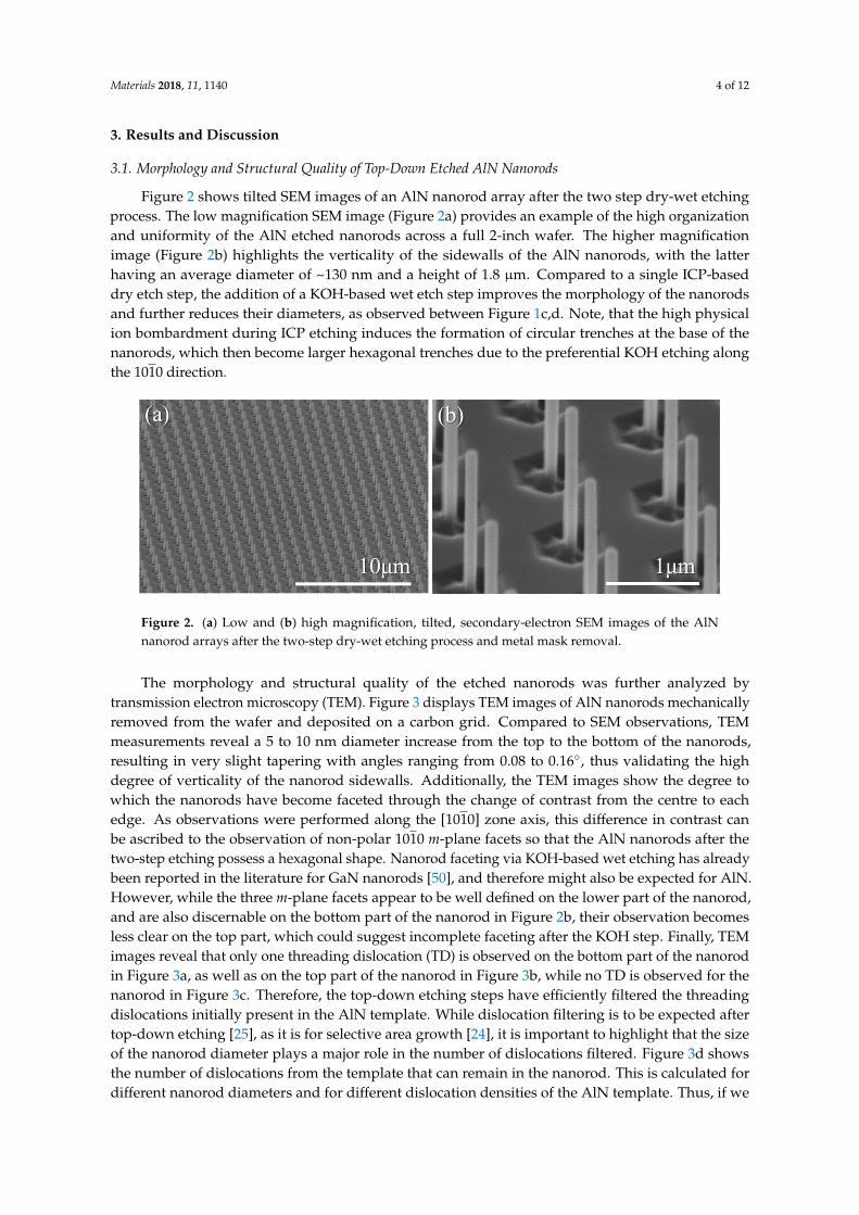
Figure 2 shows tilted SEM images of an AlN nanorod array after the two step dry-wet etchingprocess. The low magnification SEM image (Figure 2a) provides an example of the high organizationand uniformity of the AlN etched nanorods across a full 2-inch wafer. The higher magnificationimage (Figure 2b) highlights the verticality of the sidewalls of the AlN nanorods, with the latterhaving an average diameter of ~130 nm and a height of 1.8 µm. Compared to a single ICP-baseddry etch step, the addition of a KOH-based wet etch step improves the morphology of the nanorodsand further reduces their diameters, as observed between Figure 1c,d. Note, that the high physicalion bombardment during ICP etching induces the formation of circular trenches at the base of thenanorods, which then become larger hexagonal trenches due to the preferential KOH etching alongthe 1010 direction.などな博ど
などな博どなどな博ど
ƺ
Figure 2. (a) Low and (b) high magnification, tilted, secondary-electron SEM images of the AlNnanorod arrays after the two-step dry-wet etching process and metal mask removal.
The morphology and structural quality of the etched nanorods was further analyzed bytransmission electron microscopy (TEM). Figure 3 displays TEM images of AlN nanorods mechanicallyremoved from the wafer and deposited on a carbon grid. Compared to SEM observations, TEMmeasurements reveal a 5 to 10 nm diameter increase from the top to the bottom of the nanorods,resulting in very slight tapering with angles ranging from 0.08 to 0.16◦, thus validating the highdegree of verticality of the nanorod sidewalls. Additionally, the TEM images show the degree towhich the nanorods have become faceted through the change of contrast from the centre to eachedge. As observations were performed along the [1010] zone axis, this difference in contrast canbe ascribed to the observation of non-polar 1010 m-plane facets so that the AlN nanorods after thetwo-step etching possess a hexagonal shape. Nanorod faceting via KOH-based wet etching has alreadybeen reported in the literature for GaN nanorods [50], and therefore might also be expected for AlN.However, while the three m-plane facets appear to be well defined on the lower part of the nanorod,and are also discernable on the bottom part of the nanorod in Figure 2b, their observation becomesless clear on the top part, which could suggest incomplete faceting after the KOH step. Finally, TEMimages reveal that only one threading dislocation (TD) is observed on the bottom part of the nanorodin Figure 3a, as well as on the top part of the nanorod in Figure 3b, while no TD is observed for thenanorod in Figure 3c. Therefore, the top-down etching steps have efficiently filtered the threadingdislocations initially present in the AlN template. While dislocation filtering is to be expected aftertop-down etching [25], as it is for selective area growth [24], it is important to highlight that the sizeof the nanorod diameter plays a major role in the number of dislocations filtered. Figure 3d showsthe number of dislocations from the template that can remain in the nanorod. This is calculated fordifferent nanorod diameters and for different dislocation densities of the AlN template. Thus, if we

Materials 2018, 11, 1140 5 of 12
consider a homogenous dislocation density of ~1–3 × 1010 cm−2 and a nanorod diameter of ~130 nm(vertical black line), one or no dislocations should be observed in the AlN nanorod, which correlateswell with experimental data. Increasing the etched diameter core to higher values such as 500 nmcould result in an AlN nanorod containing almost ten dislocations.
などな博ど
などな博な
Figure 3. (a–c) TEM pictures of three different AlN etched nanorods acquired along the [1010] zone axis.The left and right hand-side of each image are related to the bottom and top of the nanorod, respectively.Note, the nanorod in (b) has been broken during mechanical removal and hence is shorter; (d) averagenumber of dislocations from the template which remain in the nanorod, calculated for different etchednanorod diameters as a function of the dislocation density in the planar template. The dashed lines arecontour lines to guide the eye. The vertical straight line corresponds to a nanorod diameter of 130 nm.
3.2. Morphology and Structural Quality of Bottom-Up Regrown AlN Nanorod
The AlN nanorod scaffold was subsequently placed in a MOVPE reactor for the regrowth ofAlN facets. Figure 4 presents SEM images of the resulting AlN nanorods for various AlN growth times,while Figure 5 displays the inner diameter (extracted from plan-view SEM images) and the m-planegrowth rate as a function of the growth time.
The morphology of the nanorod evolves as a function of the growth time. In the early stagesof growth, m-plane facets are visible on the nanorod sidewalls, but there is a small gap betweenneighbouring m-plane facets on the lower part. The top comprises a truncated pyramid with six (1011)semi-polar planes and a large top c-plane (Figure 4a,b). For intermediate growth times (Figure 4c,d),the sidewalls are solely comprised of m-plane facets with a truncated pyramid at the top, having asmall top c-plane. For the highest growth times (Figure 4e,f), the nanorod still has well-defined m-planesidewall facets, but the c-plane at the tip has been extinguished, leaving a complete pyramid on top.

Materials 2018, 11, 1140 6 of 12
Cross-section images, shown as insets in Figure 4, reveal the extremely good height uniformityresulting from the hybrid top-down bottom-up approach employed in this work. In addition, it can beobserved that the verticality of the nanorod sidewalls remains high until the longest growth time isreached (Figure 4f), in which the diameter becomes larger on the top part of the nanorod compared tothe bottom. As the c-plane is extinguished after 60 min and the top pyramid is completely formed,species on the slow-growing semi-polar planes can now only diffuse down the nanorod to the junctionwith the m-plane, thus resulting in a higher diameter at the top of the nanorods.
ƺ
ƺ
Figure 4. Cross-section SEM images of AlN nanorod arrays after a MOVPE regrowth time of (a) 5 min,(b) 15 min, (c) 30 min, (d) 45 min, (e) 60 min, and (f) 90 min. Each inset shows a cross-section of theAlN nanorods.
An increase of diameter as a function of growth time is observed from the SEM images in Figure 4and the graph in Figure 5. The increase is more significant in the early stages of growth (<15 min),after which the increase drops and becomes linear with growth time. The transition between higherand lower growth rate at around 15 min correlates with the complete coverage of the nanorod sidewallswith m-plane facets. For the growth conditions employed, the AlN m-plane growth rate is found tobe significantly lower than the c-plane growth rate of conventional planar AlN layers. An increaseof the growth rate from ~0.6 to ~1.7 nm·min−1 is first observed between 5 and 15 min, which thengradually decreases to stabilize at ~1 nm·min−1 after ~60 min. The low value extracted after 5 mincould be caused by an incubation or nucleation time. Once this time passed, growth takes place on them-plane and facets start to form. For the highest growth times, the nanorod diameter is observed to belower on the bottom. Therefore, the m-plane growth rate extracted from plan-view SEM pictures (i.e.,top diameter) represents the maximum value.
From these observations, the AlN regrowth time to create complete sidewall facets should bechosen with care if one wants to overgrow a quantum well, since a short growth time leads toincomplete faceting, whereas a long growth time induces preferential growth on the upper part of the

Materials 2018, 11, 1140 7 of 12
m-plane facets. For the nanorod geometry and growth conditions presented in this paper, an initialAlN growth time of 30 to 45 min would be suitable for subsequent quantum well growth.
穴沈 噺穴墜 ┻ ヂぬ にエ 訣堅剣拳建月堅欠建結 噺 岫堅沈暢潮蝶牒帳 伐 堅沈勅痛頂朕岻【訣堅剣拳建月建件兼結
などな博ど
Figure 5. The inner diameter (in black) and m-plane growth rate (in blue) as a function of the growthtime. The box plot representation displays the average (dark point in the box) and median (dark line inthe box) values, the dispersion of the measured values through the interquartile deviation (black box),and the largest and smallest values (extremities of the vertical line). Note, the outer circle of a hexagonintersects each corner, while the inner circle touches the middle of each facet, such that di = do.
√3/2.
The m-plane growth rate was then obtained by extracting the increase of the inner radius of the regrownnanorod compared to the etched nanorod, i.e., growth rate = (rMOVPE
i − retchi )/growth time.
Figure 6 shows TEM images of AlN faceted nanorods after 45 min growth. TEM measurementsconfirm the high verticality of the sidewalls with almost no fluctuation in the nanorod diameter acrossits height. Threading defects and pits are observed in Figure 6a–c, respectively. We ascribe thesedefects to TDs initially present in the AlN etched core that bend towards the lateral free surfaces andemerge on the sidewalls as pits.
穴沈 噺穴墜 ┻ ヂぬ にエ 訣堅剣拳建月堅欠建結 噺 岫堅沈暢潮蝶牒帳 伐 堅沈勅痛頂朕岻【訣堅剣拳建月建件兼結
などな博どFigure 6. (a–c) TEM images of three different AlN faceted nanorods acquired along the [1010zone axis. The left and right hand-side of each image corresponds to the bottom and the top ofthe nanorod, respectively.
Materials 2018, 11, 1140 8 of 12
3.3. Impact of the Etched Nanorod Morphology and Dimensions on the AlN Faceting
Figure 7 presents the effects of regrowing AlN on various etched AlN nanorod templates. In ourprevious work, we reported on the optimization of the dry etching conditions required to achievestraight AlN nanorods and the subsequent optimization of the MOVPE regrowth conditions to achievestraight and smooth sidewalls [48]. At this point in time, no additional KOH-based wet etch was used.In particular, we showed that the use of low pressure and a high V/III ratio enables a quasi-completecoverage of the AlN nanorods, leading to a smooth and straight sidewall profile (Figure 7b).
However, etching striations observed on the top of the nanorods after dry etching (Figure 7a)induced the formation of steps on the top part of the nanorods after regrowth (Figure 7b). In addition,the junction between neighboring m-plane facets was not completely formed on the bottom part ofthe nanorods (Figure 7b). By adding the wet-etch step and employing a two-step dry-wet etchingas presented in Figure 7c, the nanorod profile becomes straighter, and the etching striations can besuppressed, resulting in the absence of regrowth steps on the top of the nanorod (Figure 7d). The aimis to achieve m-plane facets along the entire side walls of the nanorods in order to achieve homogenousemission properties from any active region subsequently grown. This is aided by the reduction of thenumber of types of facet present in the structure in order to reduce competition in adatom incorporationon different facets. Whilst adding the wet-etch step has improved the nanorod homogeneity nearer thetop of the nanorod, for initial nanorod diameters around 400 nm, the SEM images from the regrowthstill show dark contrast between the m-planes nearer the bottom. We ascribe this to gap between them-planes rather than the existence of a-plane facets.
Figure 7. AlN etched nanorods achieved with (a) a 650-nm-diameter metal mask and a single stepdry etch, (b) a 650-nm-diameter metal mask and a two-step dry-wet etch, and (c) a 250-nm-diametermetal mask and a two-step dry-wet etch; (b,d,f) 90 min AlN faceting regrowth from (a,c,e).

Materials 2018, 11, 1140 9 of 12
In the present work, ~130 nm diameter AlN nanorods were achieved (Figure 7e) thanks to theoptimization of the fabrication process, i.e., DTL exposure and lift-off, and the two-step dry-wetetching, resulting in a complete facet recovery of the AlN nanorods (Figure 7f). Therefore, completeAlN facet recovery of smooth and straight sidewalls is achieved by a careful optimization of the initialnanorod diameter along with optimum growth conditions. However, it should be pointed out that thepitch of the nanorod array can also play a role in the facet recovery mechanism. In our case, a 1.5 µmpitch was employed to allow delivery of gas reactants to the bottom part of the nanorods. One couldexpect that for lower pitch (<500 nm), the larger filling factor would lead to preferential growth onthe top part of the nanorod and to the formation of close-packed hexagonal nanopyramids havingnon-straight sidewalls underneath [47].
3.4. Optical Properties
The optical emission of the AlN nanorods before and after regrowth was assessed by roomtemperature, high-resolution cathodoluminescence (CL) hyperspectral imaging. In the top rowof Figure 8, Figure 8b,c displays the AlN near band edge (NBE) and defect-related intensity mapsobtained after the two-step etching, alongside the corresponding SEM image in Figure 8a. In thebottom row, Figure 8d–f shows the corresponding SEM and CL maps after 45 min AlN regrowth.The defect-related emission already present in the initial AlN template could be due to O-complexesand/or Si-complexes and other native defects, such as vacancies [51,52]. Strong NBE emission between5.6–6.2 eV is observed from both samples, though after the overgrowth we can only extract NBEemission from the core of the nanorod, even when using lower acceleration energies. Whilst themeasurement conditions have changed slightly from sample to sample, we can nevertheless deducethat the relative intensity of the NBE emission has dropped slightly for the regrown sample. This ismost likely caused by an increase in material thickness, which reduces the amount of electrons reachingthe core. We suspect the reason as to why we only observe AlN NBE emission from the core is that theregrowth introduces a number of point defects in the regrown shell, which will act as effective carriertraps. On a positive note, the emission in the defect band does not noticeably increase for the regrownsample, and the defect-related emission is lower for the AlN nanorods compared to the planar layer.
Figure 8. (a) Tilted SEM image of the AlN nanorod array after the two-step dry-wet etching processand related CL intensity map extracted between (b) 5.6–6.2 eV for the AlN NBE and (c) 2.37–4.5 eV forthe defect band; (d) Tilted SEM image of the AlN nanorod array after 45 min AlN facet recovery andrelated CL intensity map extracted between (e) 5.6–6.2 eV for the AlN NBE and (f) 2.37–4.5 eV for thedefect band.

Materials 2018, 11, 1140 10 of 12
4. Conclusions
In conclusion, by employing a hybrid top-down/bottom-up approach, we fabricated a highlyuniform and organized faceted AlN nanorod scaffold. The successful fabrication of AlN nanorods withnonpolar (m-plane) facets is achieved by creating smooth vertical nanorods with a narrow diameterthanks to the combination of a two-step dry-wet etching process and by employing optimized MOVPEAlN regrowth conditions. The AlN faceted nanorods exhibit high structural and reasonable opticalquality. Such AlN nanorod templates will enable the mitigation of the quantum-confined Stark effectfor subsequent active layers, will improve the structural quality of deep-UV core-shell structures (henceincreasing the internal quantum efficiency), and will improve light extraction. Therefore, the hybridtop-down/bottom-up approach shows great promise for a novel, deep-UV core-shell architecture.
Supplementary Materials: This publication is supported by multiple data sets, which are openly available here:https://doi.org/10.15125/BATH-00522.
Author Contributions: P.-M.C. conceived the experimental work, supervised by P.A.S., P.-M.C. and P.C. performedthe DTL patterning and lift-off process. P.-M.C. carried out the nanorod fabrication, MOVPE growth experiment,and SEM characterization. P.F. carried out the TEM observations. G.K. and R.W.M. performed the CLcharacterization. All the authors contributed to analyzing and writing the results.
Funding: This research is supported by the EPSRC, UK via Grant No. EP/M015181/1, “Manufacturingnano-engineered III-nitrides”.
Conflicts of Interest: The authors declare no conflict of interest.
References
1. Anayaogu, K.C.; Ermoshkin, A.A.; Neckers, D.C.; Mejiritski, A.; Grinevich, O.; Fedorov, A.V. Performanceof the light emitting diodes versus conventional light sources in the UV light cured formulations. J. Appl.
Polym. Sci. 2007, 105, 803–808. [CrossRef]2. Morison, W.L. Phototherapy and Photochemotherapy of Skin Disease, 2nd ed.; Raven Press: New York, NY, USA, 1991.3. Hodgkinson, J.; Tatam, R.P. Optical gas sensing: A review. Meas. Sci. Technol. 2013, 24, 012004. [CrossRef]4. Wu, T.; Zha, Q.; Chen, W.; Xu, Z.; Wang, T.; He, X. Development and deployment of a cavity enhanced
UV-LED spectrometer for measurements of atmospheric HONO and NO2 in Hong Kong. Atmos. Environ.
2014, 95, 544–551. [CrossRef]5. Xu, Z.; Sadler, B.M. Ultraviolet communications: Potential and state-of-the-art. IEEE Commun. Mag. 2008,
46, 67–73.6. Vilhunen, S.; Särkkä, H.; Sillanpää, M. Ultraviolet light-emitting diodes in water disinfection. Environ. Sci.
Pollut. Res. 2009, 16, 439–442. [CrossRef] [PubMed]7. Würtele, M.A.; Kolbe, T.; Lipsz, M.; Külberg, A.; Weyers, M.; Kneissl, M.; Jekel, M. Application of GaN-based
deep ultraviolet light emitting diodes UV-LEDs for Water disinfection. Water Res. 2011, 45, 1481–1489.[CrossRef] [PubMed]
8. Kneissl, M.; Rass, J. III-Nitride Ultraviolet Emitters; Springer Series in Materials Science; Springer InternationalPublishing: Cham, Switzerland, 2016; Volume 227.
9. Zyara, A.M.; Heinonen-Tanski, H.; Veijalainen, A.-M.; Torvinen, E. UV-LEDs Efficiently Inactivate DNA andRNA Coliphages. Water 2017, 9, 46. [CrossRef]
10. Hirayama, H.; Maeda, N.; Fujikawa, S.; Toyoda, S.; Kamata, N. Recent progress and future prospects ofAlGaN-based high-efficiency deep-ultraviolet light-emitting diodes. Jpn. J. Appl. Phys. 2014, 53, 100209.[CrossRef]
11. Kneissl, M.; Kolbe, T.; Chua, C.; Kueller, V.; Lobo, N.; Stellmach, J.; Knauer, A.; Rodriguez, H.;Einfeldt, S.; Yang, Z.; et al. Advances in group III-nitride-based deep UV light-emitting diode technology.Semicond. Sci. Technol. 2011, 26, 014036. [CrossRef]
12. Martens, M.; Mehnke, F.; Kuhn, C.; Reich, C.; Kueller, V.; Knauer, A.; Netzel, C.; Hartmann, C.; Wollweber, J.;Rass, J.; et al. Performance Characteristics of UV-C AlGaN-Based Lasers Grown on Sapphire and Bulk AlNSubstrates. IEEE Photonics Technol. Lett. 2014, 26, 342–345. [CrossRef]
13. Amano, H.; Miyazaki, A.; Iida, K.; Kawashima, T.; Iwaya, M.; Kamiyama, S.; Akasaki, I.; Liu, R.; Bell, A.;Ponce, F.A.; et al. Defect and stress control of AlGaN for fabrication of high performance UV light emitters.Phys. Status Solidi 2004, 201, 2679–2685. [CrossRef]
Materials 2018, 11, 1140 11 of 12
14. Ban, K.; Yamamoto, J.; Takeda, K.; Ide, K.; Iwaya, M.; Takeuchi, T.; Kamiyama, S.; Akasaki, I.; Amano, H.Internal Quantum Efficiency of Whole-Composition-Range AlGaN Multiquantum Wells. Appl. Phys. Express
2011, 4, 052101. [CrossRef]15. Stampfl, C.; Neugebauer, J.; Van De Walle, C.G. Doping of AlxGa1−xN alloys. Mater. Sci. Eng. B 1999,
59, 253–257. [CrossRef]16. Khan, M.A.; Shatalov, M.; Maruska, H.P.; Wang, H.M.; Kuokstis, E. III-Nitride UV Devices. Jpn. J. Appl. Phys.
2005, 44, 7191. [CrossRef]17. Huang, M.-F.; Lu, T.-H. Optimization of the Active-Layer Structure for the Deep-UV AlGaN Light-Emitting
Diodes. IEEE J. Quantum Electron. 2006, 42, 820–826. [CrossRef]18. Shur, M.S.; Gaska, R. Deep-Ultraviolet Light-Emitting Diodes. IEEE Trans. Electron. Devices 2010, 57, 12–25.
[CrossRef]19. Nam, K.B.; Li, J.; Nakarmi, M.L.; Lin, J.Y.; Jiang, H.X. Unique optical properties of AlGaN alloys and related
ultraviolet emitters. Appl. Phys. Lett. 2004, 84, 5264–5266. [CrossRef]20. Taniyasu, Y.; Kasu, M. Surface 210 nm light emission from an AlN p–n junction light-emitting diode enhanced
by A-plane growth orientation. Appl. Phys. Lett. 2010, 96, 221110. [CrossRef]21. Kim, D.; Park, J.H.; Lee, J.W.; Hwang, S.; Oh, S.J.; Kim, J.; Sone, C.; Schubert, E.F.; Kim, J.K. Overcoming
the fundamental light-extraction efficiency limitations of deep ultraviolet light-emitting diodes by utilizingtransverse-magnetic-dominant emission. Light Sci. Appl. 2015, 4, e263. [CrossRef]
22. Park, J.-S.; Kim, J.K.; Cho, J.; Seonga, T.-Y. Review—Group III-Nitride-Based Ultraviolet Light-EmittingDiodes: Ways of Increasing External Quantum Efficiency. ECS J. Solid State Sci. Technol. 2017, 6, Q42–Q52.[CrossRef]
23. Coulon, P.-M.; Mexis, M.; Teisseire, M.; Jublot, M.; Vennéguès, P.; Leroux, M.; Zúñiga-Pérez, J. Double-polarityGaN micropillars grown by metalorganic vapour phase epitaxy: Cross correlation between structural andoptical properties. J. Appl. Phys. 2014, 115, 153504. [CrossRef]
24. Coulon, P.-M.; Alloing, B.; Brändli, V.; Vennéguès, P.; Leroux, M.; Zúñiga-Pérez, J. Dislocation-filtering andpolarity in the selective area growth of GaN nanowires by continuous-flow MOVPE. Appl. Phys. Express
2016, 9, 015502. [CrossRef]25. Wang, G.T.; Li, Q.; Wierer, J.J.; Koleske, D.D.; Figiel, J.J. Top-down fabrication and characterization of axial
and radial III-nitride nanowire LEDs. Phys. Status Solidi 2014, 211, 748–751. [CrossRef]26. Waag, A.; Wang, X.; Fündling, S.; Ledig, J.; Erenburg, M.; Neumann, R.; Al Suleiman, M.; Merzsch, S.; Wei, J.;
Li, S.; et al. The nanorod approach: GaN NanoLEDs for solid state lighting. Phys. Status Solidi 2011, 8,2296–2301. [CrossRef]
27. Li, S.; Waag, A. GaN based nanorods for solid state lighting. J. Appl. Phys. 2012, 111, 071101. [CrossRef]28. Ryu, H.Y.; Choi, I.G.; Choi, H.S.; Shim, J.I. Investigation of Light Extraction Efficiency in AlGaN
Deep-Ultraviolet Light-Emitting Diodes. Appl. Phys. Express 2013, 6, 062101. [CrossRef]29. Lee, D.; Lee, J.W.; Jang, J.; Shin, I.-S.; Jin, L.; Park, J.H.; Kim, J.; Lee, J.; Noh, H.-S.; Kim, Y.-I.; et al. Improved
performance of AlGaN-based deep ultraviolet light-emitting diodes with nano-patterned AlN/sapphiresubstrates. Appl. Phys. Lett. 2017, 110, 191103. [CrossRef]
30. Inoue, S.-I.; Tamari, N.; Taniguchi, M. 150 mW deep-ultraviolet light-emitting diodes with large-area AlNnanophotonic lightextraction structure emitting at 265 nm. Appl. Phys. Lett. 2017, 110, 141106. [CrossRef]
31. Bergbauer, W.; Strassburg, M.; Kölper, C.; Linder, N.; Roder, C.; Lähnemann, J.; Trampert, A.; Fündling, S.;Li, S.F.; Wehmann, H.H.; et al. Continuous-flux MOVPE growth of position-controlled N-face GaN nanorodsand embedded InGaN quantum wells. Nanotechnology 2010, 21, 305201. [CrossRef] [PubMed]
32. Choi, K.; Arita, M.; Arakawa, Y. Selective-area growth of thin GaN nanowires by MOCVD. J. Cryst. Growth
2012, 357, 58–61. [CrossRef]33. Coulon, P.-M.; Alloing, B.; Brändli, V.; Lefebvre, D.; Chenot, S.; Zúñiga-Pérez, J. Selective area growth of
Ga-polar GaN nanowire arrays by continuous-flow MOVPE: A systematic study on the effect of growthconditions on the array properties. Phys. Status Solidi 2015, 252, 1096–1103. [CrossRef]
34. Su, J.; Gherasimova, M.; Cui, G.; Tsukamoto, H.; Han, J.; Onuma, T.; Kurimoto, M.; Chichibu, S.F.;Broadbridge, C.; He, Y.; et al. Growth of AlGaN nanowires by metalorganic chemical vapor deposition.Appl. Phys. Lett. 2005, 87, 183108. [CrossRef]
Materials 2018, 11, 1140 12 of 12
35. Zheng, J.; Yang, Y.; Yu, B.; Song, X.B.; Li, X.G. [0001] Oriented Aluminum Nitride One-DimensionalNanostructures: Synthesis, Structure Evolution, and Electrical Properties. ACS Nano 2008, 2, 134–142.[CrossRef] [PubMed]
36. Yeh, T.-W.; Lin, Y.-T.; Stewart, L.S.; Dapkus, P.D.; Sarkissian, R.; O’Brien, J.D.; Ahn, B.; Nutt, S.R. InGaN/GaNMultiple Quantum Wells Grown on Nonpolar Facets of Vertical GaN Nanorod Arrays. Nano Lett. 2012,12, 3257–3262. [CrossRef] [PubMed]
37. Jung, B.O.; Bae, S.; Lee, S.; Kim, S.Y.; Lee, J.Y.; Honda, Y.; Amano, H. Emission Characteristics of InGaN/GaNCore-Shell Nanorods Embedded in a 3D Light-Emitting Diode. Nanoscale Res. Lett. 2016, 11, 215. [CrossRef][PubMed]
38. Banal, R.G.; Funato, M.; Kawakami, Y. Surface diffusion during metalorganic vapor phase epitaxy of AlN.Phys. Status Solidi 2009, 6, 599–602. [CrossRef]
39. Zhao, S.; Liu, X.; Woo, S.Y.; Kang, J.; Botton, G.A.; Mi, Z. An electrically injected AlGaN nanowire laseroperating in the ultraviolet-C band. Appl. Phys. Lett. 2015, 107, 043101. [CrossRef]
40. Zhao, S.; Liu, X.; Wu, Y.; Mi, Z. An electrically pumped 239 nm AlGaN nanowire laser operating at roomtemperature. Appl. Phys. Lett. 2016, 109, 191106. [CrossRef]
41. Sadaf, S.M.; Zhao, S.; Wu, Y.; Ra, Y.H.; Liu, X.; Vanka, S.; Mi, Z. An AlGaN Core−Shell Tunnel JunctionNanowire Light-Emitting Diode Operating in the Ultraviolet C Band. Nano Lett. 2017, 17, 1212–1218.[CrossRef] [PubMed]
42. Belloeil, M.; Gayral, B.; Daudin, B. Quantum Dot-Like Behavior of Compositional Fluctuations in AlGaNNanowires. Nano Lett. 2016, 16, 960–966. [CrossRef] [PubMed]
43. Bengoechea-Encabo, A.; Albert, A.; Müller, M.; Xie, M.-Y.; Veit, P.; Bertram, F.; Sanchez-Garcia, M.A.;Zúñiga-Pérez, J.; Mierry, P.D.; Christen, J.; et al. Selective Area Growth of AlN/GaN Nanocolumns on(0001) and (11–22) GaN/Sapphire for SemiPolar and Non-Polar AlN Pseudo-Templates. Nanotechnology
2017, 28, 365704. [CrossRef] [PubMed]44. Le Boulbar, E.D.; Gîrgel, I.; Lewins, C.J.; Edwards, P.R.; Martin, R.W.; Šatka, A.; Allsopp, D.W.E.; Shields, P.A.
Facet recovery and light emission from GaN/InGaN/GaN core-shell structures grown by metal organicvapour phase epitaxy on etched GaN nanorod arrays. J. Appl. Phys. 2013, 114, 094302. [CrossRef]
45. Le Boulbar, E.D.; Edwards, P.R.; Vajargah, S.H.; Griffiths, I.; Gîrgel, I.; Coulon, P.-M.; Cherns, D.; Martin, R.W.;Humphreys, C.J.; Bowen, C.R.; et al. Structural and Optical Emission Uniformity of m-Plane InGaN SingleQuantum Wells in Core–Shell Nanorods. Cryst. Growth Des. 2016, 16, 1907–1916. [CrossRef]
46. Li, C.; Wright, J.B.; Liu, S.; Lu, P.; Figiel, J.J.; Leung, B.; Chow, W.W.; Brener, I.; Koleske, D.D.; Luk, T.S.;et al. Nonpolar InGaN/GaN Core–Shell Single Nanowire Lasers. Nano Lett. 2017, 17, 1049–1055. [CrossRef][PubMed]
47. Tian, Y.; Yan, J.; Zhang, Y.; Zhang, Y.; Chen, X.; Guo, Y.; Wang, J.; Li, J. Formation and characteristics ofAlGaN-based three-dimensional hexagonal nanopyramid semi-polar multiple quantum wells. Nanoscale
2016, 8, 11012–11018. [CrossRef] [PubMed]48. Coulon, P.-M.; Kusch, G.; Le Boulbar, E.D.; Chausse, P.; Bryce, C.; Martin, R.W.; Shields, P.A. Hybrid
Top-Down/Bottom-Up Fabrication of Regular Arrays of AlN Nanorods for Deep-UV Core-Shell LEDs.Phys. Status Solidi 2017, 6, 599–602. [CrossRef]
49. Edwards, P.R.; Jagadamma, L.K.; Bruckbauer, J.; Liu, C.; Shields, P.; Allsopp, D.; Wang, T.;Martin, R.W. High-Resolution Cathodoluminescence Hyperspectral Imaging of Nitride Nanostructures.Microscopy Microanal. 2012, 18, 1212–1219. [CrossRef] [PubMed]
50. Li, Q.; Wright, J.B.; Chow, W.W.; Luk, T.S.; Brener, I.; Lester, L.F.; Wang, G.T. Single-Mode GaN NanowireLasers. Opt. Express 2012, 20, 17873–17879. [CrossRef] [PubMed]
51. Bryan, Z.; Bryan, I.; Bobea, M.; Hussey, L.; Kirste, R.; Sitar, Z.; Collazo, R. Homoepitaxial AlN thin filmsdeposited on m-plane (1¯100) AlN substrates by metalorganic chemical vapor deposition. J. Appl. Phys. 2014,115, 133503. [CrossRef]
52. Dadgar, A.; Krost, A.; Christen, J.; Bastek, B.; Bertram, F.; Krtschil, A.; Hempel, T.; Bläsing, J.; Haboeck, U.;Hoffmann, A. MOVPE growth of high-quality AlN. J. Cryst. Growth 2006, 297, 306–310. [CrossRef]
© 2018 by the authors. Licensee MDPI, Basel, Switzerland. This article is an open accessarticle distributed under the terms and conditions of the Creative Commons Attribution(CC BY) license (http://creativecommons.org/licenses/by/4.0/).