COSMOS Motion Tutorial
11
Four-Bar Mechanism Design Using COSMOS Motion By: Jesse Peterson For: Dr. Max Gassman 1
-
Upload
fabio-medeiros -
Category
Documents
-
view
17 -
download
1
description
ANALISE DE ELEMENTOS SOLIDWORKS
Transcript of COSMOS Motion Tutorial
Four-Bar Mechanism Design Using COSMOS Motion
By: Jesse Peterson For: Dr. Max Gassman
1

Introduction
This is a tutorial explaining how to design a four-bar mechanism using COSMOS Motion. This particular four-bar is a Grashoff crank-rocker mechanism because the driver can be driven continuously and the other arm rocks back and forth. This tutorial assumes that the user has a general knowledge of SolidWorks and engineering. Drawing the Bars Go to Start → Programs → SolidWorks 2001+ → SolidWorks Education Edition Click on File → New → Part Go to Tools → Add Ins → Check the box marked COSMOS/Motion and click “OK”
Note: To set the units to English, go to Tools → Options → Document Properties → Units → select English.
Figure 1: Standard Icons
Note: To see what an icon is for, let the curser rest over the icon until a name appears.
Sketch Tools
Manager Tabs
Standard Views Icons
Boss Extrude and Cut Extrude
Feature Manager Tree
1) Select the Front plane from the feature manager tree by clicking on Front (see Figure 1).
2) Select the Sketch icon on the right hand side of the window. 3) Select the Rectangle icon located below the sketch icon. 4) Place the curser on the origin. When the curser turns orange, it has snapped to the
origin. 5) Create the rectangle by depressing the left mouse button and then dragging and
releasing. 6) Click on the Dimension icon located on the sketch tool bar. 7) Click on the left vertical line and set the required dimension to 1.5 inches. Repeat
for the top horizontal line giving it a dimension of 1.5 inches also.
2

8) Select the Centerpoint Arc icon located below the sketch icon. 9) Click on the center of the top line of the rectangle (a diamond will show when the
center point is found). Then click on the top right corner of the rectangle. Sweep the arc up over the rectangle and then click on the top left corner of the rectangle. An arc should now be created.
10) Delete the top line of the rectangle. 11) Dimension the arc until it completely turns black. These dimensions should be a
radius of .75 inches and a distance from the center point to the bottom line of the rectangle of 1.5 inches (see Figure 2).
Figure 2: Base of Bar_4_2
12) To extrude the shape, select the Extrude icon located on the left hand side of the
window. Select the extrude to be from midplane with a depth of .5 inches. Click on the green check mark to say OK (see Figure 3).
Figure 3: Extrusion of Bar_4_2
3
Note: If the standard view icons are not on the screen, right click by any tool bar and then select the standard views.
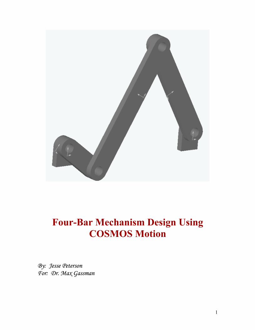
13) From the standard views icon, select the front view. 14) Select the Sketch icon and click on the front plane of the drawing. 15) Select the Circle icon located below the sketch icon. 16) Run the mouse along the radius of the arc, until the center point of the arc
appears. When this appears, click and hold on the center point with the left mouse button and drag a circle out and then release.
17) Set the dimension of this circle to .75 inches in diameter using the Dimension icon.
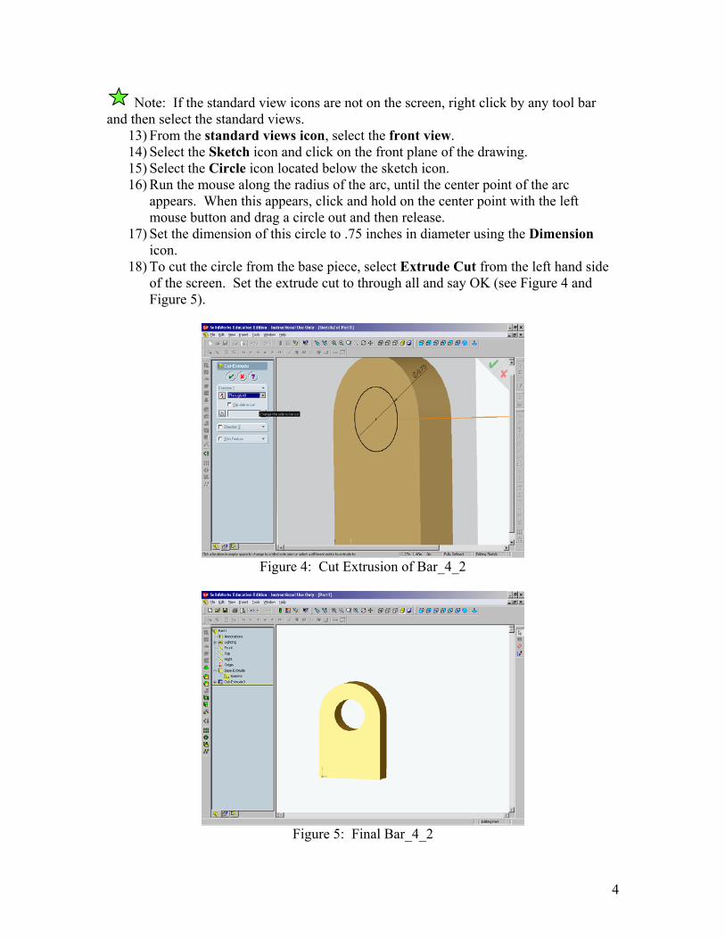
18) To cut the circle from the base piece, select Extrude Cut from the left hand side of the screen. Set the extrude cut to through all and say OK (see Figure 4 and Figure 5).
Figure 4: Cut Extrusion of Bar_4_2
Figure 5: Final Bar_4_2
4
19) Save this file as Bar_4_2. 20) Repeat steps 1-19 for Bar_5_2 using the same dimensions. 21) For bars 1-3, repeat steps 1-19 but also add an arc and hole to the other end of
the bar. The arc should be added before the base is extruded, and remember to delete the bottom line of the rectangle. The bottom hole should be added immediately after the top hole is produced. Save these files as Bar_1_2. Bar_2_2, Bar_3_2. The length from the center of the two holes should be 3.116 inches for bar one, 10.376 inches for bar two, and 8.224 inches for bar three.
Assembling the Four-Bar
1) In the feature manager tree, click on front. 2) Go to Insert → Component → From File 3) Click on Bar_4_2 and then click on Open
Note: When inserting components, make sure that you have selected the front view using the standard view icons.
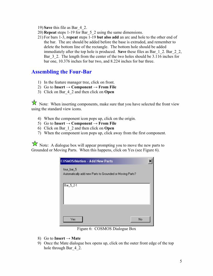
4) When the component icon pops up, click on the origin. 5) Go to Insert → Component → From File 6) Click on Bar_1_2 and then click on Open 7) When the component icon pops up, click away from the first component.
Note: A dialogue box will appear prompting you to move the new parts to Grounded or Moving Parts. When this happens, click on Yes (see Figure 6).
Figure 6: COSMOS Dialogue Box
8) Go to Insert → Mate 9) Once the Mate dialogue box opens up, click on the outer front edge of the top
hole through Bar_4_2.
5
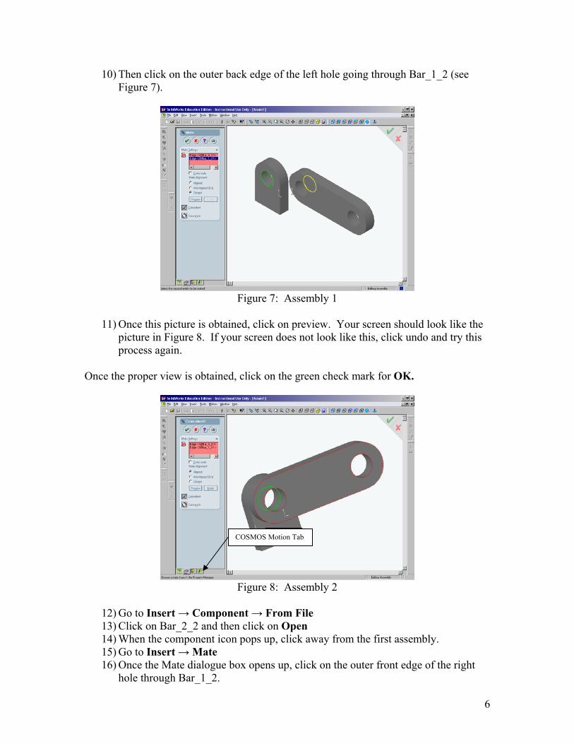
10) Then click on the outer back edge of the left hole going through Bar_1_2 (see Figure 7).
Figure 7: Assembly 1
11) Once this picture is obtained, click on preview. Your screen should look like the
picture in Figure 8. If your screen does not look like this, click undo and try this process again.
Once the proper view is obtained, click on the green check mark for OK.
COSMOS Motion Tab
Figure 8: Assembly 2
12) Go to Insert → Component → From File 13) Click on Bar_2_2 and then click on Open 14) When the component icon pops up, click away from the first assembly. 15) Go to Insert → Mate 16) Once the Mate dialogue box opens up, click on the outer front edge of the right
hole through Bar_1_2.
6
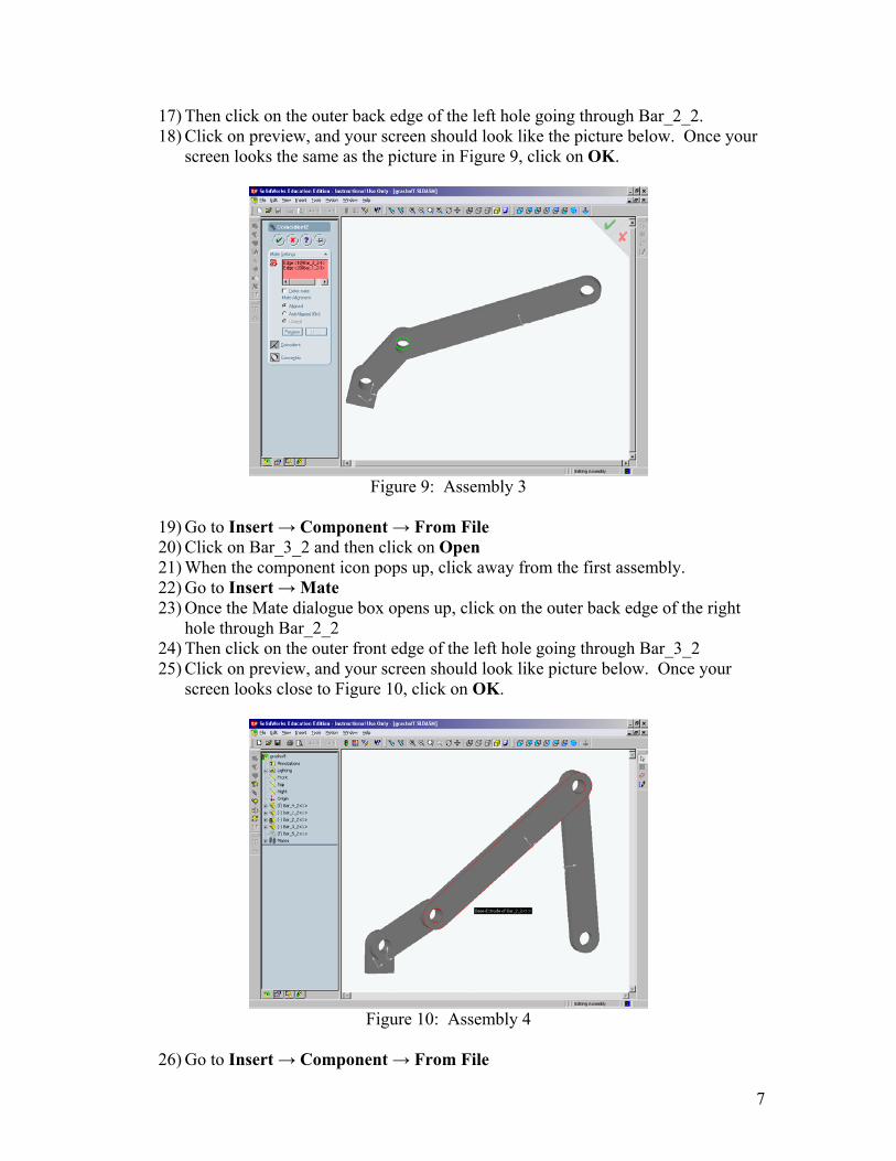
17) Then click on the outer back edge of the left hole going through Bar_2_2. 18) Click on preview, and your screen should look like the picture below. Once your
screen looks the same as the picture in Figure 9, click on OK.
Figure 9: Assembly 3
19) Go to Insert → Component → From File 20) Click on Bar_3_2 and then click on Open 21) When the component icon pops up, click away from the first assembly. 22) Go to Insert → Mate 23) Once the Mate dialogue box opens up, click on the outer back edge of the right
hole through Bar_2_2 24) Then click on the outer front edge of the left hole going through Bar_3_2 25) Click on preview, and your screen should look like picture below. Once your
screen looks close to Figure 10, click on OK.
Figure 10: Assembly 4
26) Go to Insert → Component → From File
7

27) Click on Bar_5_2 and then click on Open 28) When the component icon pops up, click away from the first assembly. 29) Go to Insert → Mate 30) Once the Mate dialogue box opens up, click on the front right vertex of Bar_4_2
and the front left vertex of Bar_5_2. Then click on the distance box and set it equal to 10 inches. Click on preview, and then say OK (see Figure 11).
Distance Box
Figure 11: Fixing the Base Points
31) Go to Insert → Mate 32) Once the Mate dialogue box opens up, click on the front bottom edge of Bar_4_2
and the front bottom edge of Bar_5_2. Then click on the distance box and set it equal to 0 inches. Click on preview, and then say OK.
Applying Joints
1) Go to Motion → Joints → Revolute 2) For the box marked “Select 1st Component”, click on Bar_4_2. For the 2nd
component, click on Bar_1_2. For the location, select the inside edge of the circle (see Figure 12).
8
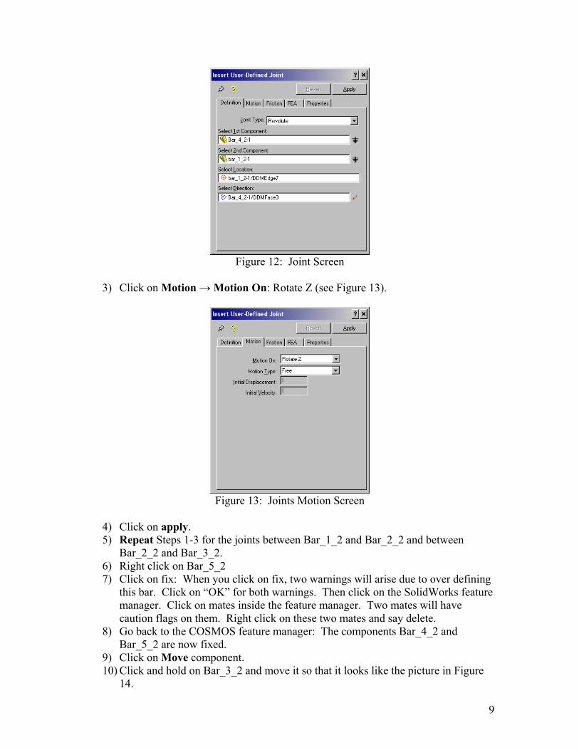
Figure 12: Joint Screen
3) Click on Motion → Motion On: Rotate Z (see Figure 13).
Figure 13: Joints Motion Screen
4) Click on apply. 5) Repeat Steps 1-3 for the joints between Bar_1_2 and Bar_2_2 and between
Bar_2_2 and Bar_3_2. 6) Right click on Bar_5_2 7) Click on fix: When you click on fix, two warnings will arise due to over defining
this bar. Click on “OK” for both warnings. Then click on the SolidWorks feature manager. Click on mates inside the feature manager. Two mates will have caution flags on them. Right click on these two mates and say delete.
8) Go back to the COSMOS feature manager: The components Bar_4_2 and Bar_5_2 are now fixed.
9) Click on Move component. 10) Click and hold on Bar_3_2 and move it so that it looks like the picture in Figure
14.
9

11) Click OK
Figure 14: Moving the Assembly
12) Go to Insert → Mate 13) Once the Mate dialogue box opens up, click on the outer back edge of the right
hole through Bar_3_2. 14) Then click on the outer front edge of the top hole going through Bar_5_2. Then
select the concentric button and click on preview. If this works, click on OK 15) Go to Motion → Joints → Revolute 16) For the box marked “Select 1st Component”, click on Bar_5_2. For the 2nd
component, click on Bar_3_2. For the location, select the inside edge of the circle.
17) Click on Motion → Motion On: Rotate Z 18) Click on apply.
Your assembly should look like Figure 15:
Moving Parts
Grounded Parts
Joints
Figure 15: Assembly with Joints
10
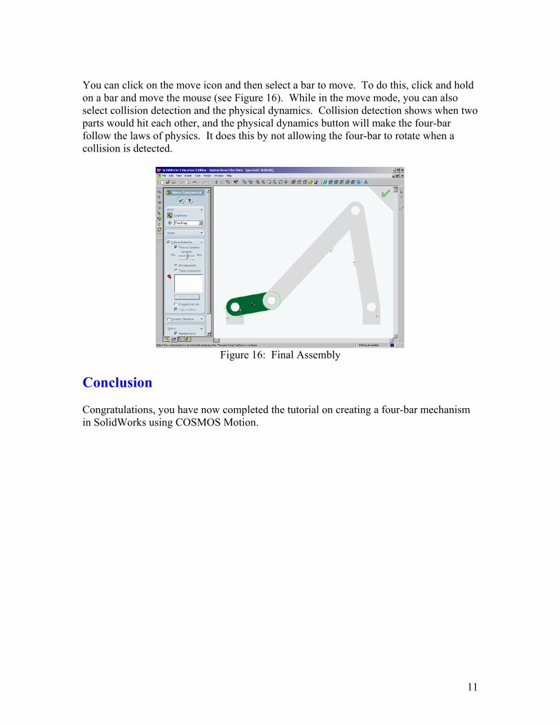
You can click on the move icon and then select a bar to move. To do this, click and hold on a bar and move the mouse (see Figure 16). While in the move mode, you can also select collision detection and the physical dynamics. Collision detection shows when two parts would hit each other, and the physical dynamics button will make the four-bar follow the laws of physics. It does this by not allowing the four-bar to rotate when a collision is detected.
Figure 16: Final Assembly
Conclusion Congratulations, you have now completed the tutorial on creating a four-bar mechanism in SolidWorks using COSMOS Motion.
11