Corporation of the Town of Collingwood Development... · July 2007 1 1 General Requirements 1.1...
127
July 2007 i Corporation of the Town of Collingwood Development Standards
Transcript of Corporation of the Town of Collingwood Development... · July 2007 1 1 General Requirements 1.1...

July 2007
i
Corporation of the Town of Collingwood
Development Standards

July 2007
i

July 2007
i
Town of Collingwood - Development StandardsINDEX
1 General Requirements ........................................................................................................11.1 Introduction.................................................................................................................................... 11.2 Definitions....................................................................................................................................... 11.3 Submissions to Government Agencies ......................................................................................... 21.4 Pre-Servicing Policy for Subdivision Development .................................................................... 21.5 Model Homes and/or Sales Office ................................................................................................ 41.6 Subdivision Agreement Schedules................................................................................................ 61.7 Administration Fees, Securities, Development Charges ............................................................ 6
2 Design Submissions ............................................................................................................92.1 Introduction.................................................................................................................................... 92.2 First Submission to the Engineering Department....................................................................... 92.3 Second Submission to the Engineering Department................................................................. 112.4 Interim Submissions .................................................................................................................... 122.5 Final Submission to the Engineering Department.................................................................... 12
3 Drawings............................................................................................................................133.1 Specifications for Engineering Drawings: ................................................................................. 133.2 General Drawing Requirements................................................................................................. 143.3 Computer Aided Drawings(CAD).............................................................................................. 143.4 General Plans ............................................................................................................................... 143.4.1 General Servicing Plans ..................................................................................................143.4.2 Composite Utility Plan.....................................................................................................153.5 Storm Drainage Plans.................................................................................................................. 153.6 Grading Plans............................................................................................................................... 163.7 Plan-Profile Drawings ................................................................................................................. 163.8 Erosion and Sediment Control Plans ......................................................................................... 173.9 Park Development ....................................................................................................................... 173.10 Trail and Walkways .................................................................................................................... 173.11 Landscaping ................................................................................................................................. 183.12 As-Constructed Drawings ........................................................................................................... 193.12.1 General..............................................................................................................................193.12.2 Storm Sewers...................................................................................................................193.12.3 Sanitary Sewers................................................................................................................203.12.4 Watermains ......................................................................................................................203.12.5 Roadways ..........................................................................................................................204 Design Requirements ........................................................................................................214.1 Introduction.................................................................................................................................. 214.2 Storm Drainage System............................................................................................................... 214.2.1 Sewer System....................................................................................................................214.2.2 Maintenance .....................................................................................................................214.2.3 Storm Sewer Design.........................................................................................................22
4.2.3.1 Run-off Calculations .......................................................................................224.2.3.2 Storm Sewer Requirements ...........................................................................234.2.3.3 Maintenance Hole Requirements...................................................................264.2.3.4 Catchbasin Requirements...............................................................................27

July 2007
ii
4.2.3.5 Roof Leaders, Foundation Drains and Storm Connections ................................284.2.3.6 Channel, Culvert and Overland Flow ...........................................................284.2.3.7 Culverts and Bridges.......................................................................................294.2.3.8 Open Channels.................................................................................................294.2.3.9 Watercourse Erosion and Bank Stability......................................................304.2.3.10 Overland Flow Routes.....................................................................................304.2.3.11 Inlet/Outlet Structures ....................................................................................304.2.3.12 Stormwater Management Ponds ....................................................................31
4.2.4 Stormwater Quantity Control ........................................................................................334.2.4.1 Stormwater Management Requirements...........................................................334.2.4.2 On Site Stormwater Management Reports...................................................33
4.2.5 Stormwater Quality Control...........................................................................................344.2.6 Hydrologic and Hydraulic Studies .................................................................................344.2.7 Meteorology ......................................................................................................................354.3 Sanitary Sewer System ................................................................................................................ 364.3.1 Sewer System....................................................................................................................364.3.2 Maintenance .....................................................................................................................364.3.3 Sanitary Sewer Design.....................................................................................................36
4.3.3.1 Design Flows ....................................................................................................364.3.3.2 Sanitary Sewer Requirements ............................................................................374.3.3.3 Sanitary Maintenance Hole Requirements.......................................................394.3.3.4. Sanitary Connections .........................................................................................41
4.4 Water Supply System .................................................................................................................. 414.4.1 Watermains .......................................................................................................................414.4.2 Maintenance .....................................................................................................................424.4.3 Watermain Design ...........................................................................................................42
4.4.3.1 Design Criteria.................................................................................................424.4.3.2 Flow Calculations ............................................................................................43
4.4.4 Watermain Requirements ...............................................................................................444.5 Roadways...................................................................................................................................... 474.5.1 Road Works......................................................................................................................474.5.2 Maintenance .....................................................................................................................484.5.3 Geometric Design .............................................................................................................484.5.4 Driveway Entrances.........................................................................................................484.5.5 Special Road Designs .......................................................................................................494.5.7 Top Course Asphalt .........................................................................................................494.5.8 Curbs and Gutters ..........................................................................................................504.6 Street Name And Traffic Signs................................................................................................... 504.6.1 Plan....................................................................................................................................504.6.2 Street Signs .......................................................................................................................504.7 Roadway Markings...................................................................................................................... 514.8 Traffic Signals .............................................................................................................................. 514.9 Streetlighting ................................................................................................................................ 514.9.1 Lighting Levels and Uniformity Ratio ...........................................................................524.9.2 Light Source .....................................................................................................................524.9.3 Light Fixture and Pole.....................................................................................................524.9.4 Approval and Construction ............................................................................................524.10 Pedestrian Ways........................................................................................................................... 53

July 2007
iii
4.10.1 Sidewalks and Walkways ................................................................................................534.10.2 Location ...........................................................................................................................534.10.3 Specification......................................................................................................................534.10.4 Trailways ..........................................................................................................................534.11 Fencing ......................................................................................................................................... 544.12 Residential Lot Drainage And Sodding ..................................................................................... 544.12.1 General..................................................................................Error! Bookmark not defined. 4.12.2 Lot Grading Criteria .......................................................................................................554.12.3 Sodding..................................................................................Error! Bookmark not defined. 4.12.4 Retaining Walls ................................................................................................................554.13 Block Grading .............................................................................................................................. 564.14 Erosion And Sediment Control .................................................................................................. 574.14.1 General..............................................................................................................................574.14.2 Catchbasin Sediment Control.........................................................................................574.14.3 Stone Pad Construction Entrance - Construction Access ............................................574.15 Utilities .......................................................................................................................................... 584.16 Canada Post.................................................................................................................................. 584.17 Landscaping ................................................................................................................................. 584.17.1 General Streetscape Standards.......................................................................................584.17.2 Notes for Streetscape Submission Drawings .................................................................584.17.3 List of Details and Specifications....................................................................................594.17.4 Minor Road Street Trees.................................................................................................604.17.5 Corner Lot Treatments ...................................................................................................604.17.6 General Planting Considerations for Internal Streets..................................................604.17.7 Standards and Guidelines for Naturalization Areas ....................................................614.17.8 Notes for Naturalization Submission Drawings ............................................................615 Geotechnical..............................................................................................................................615.1 Geotechnical Engineering Requirements .................................................................................. 615.2 Inspection - Consultants.............................................................................................................. 62
6 Lot Site Grading.......................................................................................................................636.1 Lot Grading Submission Procedure...............................................................................636.2 Lot Grading Inspection and Certification .....................................................................646.3 Block Grading ..................................................................................................................657 Landscaping Implementation Procedures .......................................................................657.1 Streetscape Works ....................................................................................................................... 657.2 Naturalization Works.................................................................................................................. 667.3 Maintenance Agreement for Naturalization Areas .................................................................. 667.4 Implementation of Streetscape Designs Flow Chart No. 1....................................................... 687.5 Implementation of Naturalization Designs Flow Chart No. 2 ................................................. 69
8 Standard Drawings - Index...............................................................................................70

July 2007
0

July 2007
1
1 General Requirements
1.1 Introduction
The Town of Collingwood Development Standards presented here are intended as guidelines for land development to aid in the uniform design throughout the Municipality. Innovative technological changes that improve or maintain the quality of the design on a life cycle cost basis may be considered at the discretion of the Town’s Engineering Department.
These standards are to be read in conjunction with the Ontario Provincial Standard Specifications (OPSS), the Ontario Provincial Standard Drawings (OPSD), the Town of Collingwood Standard Drawings and the Town of Collingwood Standard Subdivision Agreement. In the case of a discrepancy the Town Standards shall prevail.
It is the applicant’s responsibility to obtain and check with the Town of Collingwood for new revisions. Copies are available from the Town of Collingwood or can be downloaded from the web site at www.town.collingwood.on.ca; standard drawings are available on CD in ACAD format.
1.2 Definitions
In this specification the following definitions shall apply:
“Town” shall mean the Town of Collingwood.
“Contractor” shall mean the firm of Contractors, the company or individual acting as the Contractor and having entered into a contract with the Developer/Owner to install the services.
“Developer(s)/Owner(s)” shall mean the person(s) appearing on the subdivision agreement with the Corporation of the Town of Collingwood.
“Town Representative” shall mean any person assigned to a project by the Town to carry out work on their behalf. The name of the Representative shall be specified prior to the start of construction on any project.
“Consultant” shall mean professional engineers licensed to practice in Ontario and shall be responsible for the preparation of drawings and specifications to the satisfaction of the Town’s Engineering Department. The Consultant shall act on behalf of the Developer/Owner.
“AWWA” shall mean the American Water Works Association.
“CMUS” shall mean the Collingwood Municipal Utility Services.

July 2007
2
“COLLUS” shall mean the Collingwood Utility Services Corp.
“CPU” shall mean Collingwood Public Utilities Municipal Services Board
“CSA” shall mean the Canadian Standards Association.
“DFO” shall mean the Department of Fisheries and Oceans, Canada.
“MNR” shall mean the Ontario Ministry of Natural Resources.
“MOE” shall mean the Ontario Ministry of the Environment.
“MTO” shall mean the Ontario Ministry of Transportation.
“NVCA” shall mean the Nottawasaga Valley Conservation Authority.
“OHBDC” shall mean the Ontario Highway Bridge Design Code.
“OPSD” shall mean the Ontario Provincial Standard Drawings.
“OPSS” shall mean the Ontario Provincial Standard Specification.
1.3 Submissions to Government Agencies
The Consultant shall deal directly with the Ministry of the Environment (MOE), Ministry of Natural Resources (MNR), Nottawasaga Valley Conservation Authority (NVCA), Department of Fisheries and Oceans (DFO) and any other government agencies for works that fall within their jurisdiction. It is the responsibility of the Consultant to ensure that all correspondence, comments and approvals are provided to the Engineering Department.
1.4 Pre-Servicing Policy for Subdivision Development
Subsequent to Draft Plan Approval and prior to execution of a Subdivision Agreement, the Town may consider agreeing to pre-servicing of subdivision at the owner’s risk when the following conditions have been met:
a) Written acceptance from the Town and the executive Director of CMUS for specific works for which pre-servicing can proceed.
b) Engineering drawings have been accepted for construction for the works under consideration.

July 2007
3
c) Written approval of various agencies, e.g., MOE, NVCA, MNR, MTO, Ministry of Citizenship, Culture and Recreation, where they relate to installation of services permitted by pre-servicing.
d) Written confirmation from utility companies including, but not limited to, COLLUS, Rogers Cable and Enbridge Consumers Gas, that satisfactory agreement has been reached for provision of respective services.
e) Upon approval of the pre-servicing application, the Developer must execute and deposit with the Engineering Dept. a pre-servicing agreement.
f) No permission will be given to construct external services prior to full registration unless a Letter of Credit has been deposited with the Town, for the total cost of the services and all restoration. Connections to existing services may not be permitted until the plan is registered.
g) All other documents considered necessary to the works under the Pre-servicing Agreement including, 300 mm reserves, easements, etc., must be approved as to form and description.
h) The engineering and legal fees for the Town must be paid to the Town prior to the commencement of any works.
i) The required Insurance Certificate is to be submitted as per Pre-servicing Agreement. A certified cheque to cover the insurance deductible is to be attached.
j) A cash or Letter of Credit deposit as security for possible emergency maintenance work by the Town is to be submitted as required by the Engineering Department (5% of Schedule ‘E’, or a maximum of $25,000.00). The deposit is to be returned at the time of registration of the subdivision.
k) Any required rezoning by-laws must be in effect.
l) If the underground pre-servicing has been completed prior to the registration of the plan of subdivision, the Town will not require the full value of the Letter of Credit provided an appropriate reduction request has been submitted and approved by the Engineering Department.
m) Above ground works will not be permitted to commence unless approved by the Town.
July 2007
4
1.5 Model Homes and/or Sales Office
1.5.1 Model Homes
Subsequent to Draft Plan Approval and prior to execution of a Subdivision Agreement, the Town may consider allowing the construction of model homes, which may or may not be used as a sales office, at the owner’s risk when the following conditions have been met:
a) A Pre-Servicing Agreement has been executed and all requirements met.
b) Zoning for the proposed development is in place
c) An agreement for the construction of model homes has been executed with the Town dealing with:
� Provision of a builder’s road � Provision of fire protection � Provision of services (sewer, water, hydro) if available. If not Fire Dept. approval
will be required. � The overall grading plan has been approved and there has been preliminary
acceptance of the drainage system for the model home lots. � For each model home building permit application, security is provided to the Town
in the amount of $10,000.00 to ensure that the obligations of the Developer are carried out as required by the terms of the Agreement or provide for the demolition and removal of the structure if the subdivision plan does not proceed to registration within one year.
� Confirmation that the model homes shall not be occupied until after the registration of the Subdivision Agreement Plan and all requirements within the Subdivision Agreement are met.
� Confirmation that issuance of building permits for model homes is entirely at the risk of the Developer and without liability or responsibility to the Municipality. The Developer shall indemnify the Municipality from all damages arising in connection with the issuance of building permits for model homes.
� Confirmation that the Developer agrees that the use of model home lots shall be restricted to the following: parking; a sales office; model homes display.
� The number of model homes permitted. One model unit will be allowed for every ten (10) units however the total shall not exceed five (5).
1.5.2 Sales Office
In the event the owner intends to utilize a trailer or temporary structure or combination of both as a sales office subsequent to Draft Plan Approval or registration of a Site Plan Agreement and prior to registration of a Plan of Subdivision or Condominium the Town may consider allowing the construction under the following conditions:

July 2007
5
a) The sales office is to be located on a proposed lot fronting on an existing opened road allowance.
b) Zoning for the proposed development is in place
c) An agreement for the sales office has been executed with the Town dealing with:
� An acceptable site plan � Provision of fire protection � Provision of services (sewer, water, hydro) if available. If not Fire Dept. approval
will be required. � The overall grading plan has been approved and there has been preliminary
acceptance of the drainage system for the sales office lot. � Security is provided to the Town in the amount of $10,000.00 to ensure that the
obligations of the Developer are carried out as required by the terms of the Agreement or provide for the demolition and removal of the structure if the subdivision plan does not proceed to registration within one year.
� Confirmation that issuance of a building permit for the sales office is entirely at the risk of the Developer and without liability or responsibility to the Municipality. The Developer shall indemnify the Municipality from all damages arising in connection with the issuance of building permits for the sales office.
� Confirmation that the Developer agrees that the use of the sales office lot shall be restricted to parking and the sales office.
� One sales office will be allowed for marketing homes within the development

July 2007
6
1.6 Subdivision Agreement Schedules
The following schedules will be required under the Subdivision Agreement:
SCHEDULE “A”- Description of Lands affected by this Agreement
SCHEDULE "B"- List of Engineering Drawings
SCHEDULE “B-2”- Draft Plan of Subdivision
SCHEDULE “C”- List of Easements and Transfers to be granted
SCHEDULE “D”- Estimated costs of Public Works
SCHEDULE “E”- Unsuitable Lots
SCHEDULE “F”- Architectural Guidelines
SCHEDULE “G”- Services to be Installed and Constructed, and Specifications
SCHEDULE "H"- No Occupancy Agreement
SCHEDULE "I"- Form of Letter of Credit
SCHEDULE "J"- Restrictive Covenants
1.7 Administration Fees, Securities, Development Charges
The administration fees, securities and development charges applicable to subdivision development are stipulated in the subdivision agreement. Reductions in securities will be considered in accordance with the provisions of the subdivision agreement. A sample letter is enclosed overleaf.

July 2007
7
SCHEDULE ‘D’
SUBDIVISION: DEVELOPER: CONSULTING ENGINEER:
SUMMARY
A. Town Works
Internal Work Rough Grading $__________ Sanitary Sewers $__________ Watermain $__________ Roads To Base Asphalt $__________ Storm Drainage Works $__________ Storm Water Management Facilities $__________ Top Curb and Sidewalk $__________ Top Asphalt $__________ Street lights $__________ Street Signs and Barricades $__________ Streetscape, Landscaping and Boulevard Sodding $__________ Fencing $__________ Sub-Total $__________
External Work Watermain $__________ Sanitary Sewer $__________ Storm Sewer $__________ Roads to Top Asphalt $__________ Sub-Total $__________Internal & External Sub-Total $__________Contingencies allowance 5% $__________ Sub-Total $__________Engineering 5% $__________
Total $__________
B. Town of Collingwood Administration Fees
Town Eng. Review/Supervision Fee at 4% ($10,000 min) $__________ Lot grading ____ lots at $1,000.00 per lot ($25,000. max.) $__________
C. Notes:
1. Lot grading deposits will be held back on the Letter of Credit, in order to secure that adequate lot grading and drainage is maintained to the satisfaction of the Town of Collingwood.

July 2007
8
Sample Letter - Request For Reduction In Letter of Credit
Date:
Town of Collingwood 97 Hurontario Street Box 157Collingwood, Ontario L9Y 3Z5
Attention: Town Engineer
Re: (Name of Subdivision) Plan.
On behalf of the owners of the above development, we would appreciate your consideration and approval of a reduction in the amount of the letter of credit held by the Town as performance and maintenance security.
We have attached hereto a summary listing the value of the work completed to date, based upon Schedule D of the Subdivision Agreement revised as noted to reflect all required alterations to the works. The current value of securities is calculated as follows:
1) Value of outstanding work $ (incl. contingency and engineering fees)
2) 10% of original securities $
3) Lot Grading Deposit $_______________
Total $
We are also attaching a Statutory Declaration by the owner that all outstanding accounts relative to work in this subdivision have been paid.
Yours very truly,
(Signature of Engineer) Name of Engineering Firm

July 2007
9
2 Design Submissions
2.1 Introduction
This section outlines the required submissions to be made to the Collingwood Engineering Department. All submissions are to be coordinated by the Consulting Engineer.
Second and Final submissions are not to be made until the Town’s comments regarding the first and second submission, respectively, have been received and incorporated.
Prints of drawings for all submissions shall be in accordance with Town standards and each print shall be stamped with the submission number (1, 2, or 3) and date of submission.
All submissions are to be accompanied by a CD/DVD containing all documents, reports, engineering drawings, and correspondence in a *.PDF format. This is required as per Section 1.1 of Bill 51, where all materials that are to be filed as part of an application are to be made available to the public.
2.2 First Submission to the Engineering Department
The following submissions shall be compiled and submitted to the Town simultaneously.
Engineering Submission
1) A Letter of Retainer from the Consulting Engineer stating that they have been engaged for the design and general construction inspection of all works, and coordination of sub-consultants.
2) Five complete sets of the following drawings are required: � Proposed Plan for Registration � Cover Sheet � General servicing plan � Composite utility plan � Storm drainage plans � Erosion and Sediment control plan(s) � Plan and profile drawings � Miscellaneous and special detail drawings � Grading plan � Landscape plan � Grading plans for park blocks � Grading plan for school blocks � Copies of detail drawings for outlets and watercourse improvements � Copy of draft M Plan

July 2007
10
3) Ten copies of the General Servicing Plan and the Landscape Plan for circulation in advance of the first Development Committee Meeting
4) Two copies of the Storm Water Management Report and storm sewer calculations on standard design sheets
5) Two copies of water supply and distribution report providing calculations to support the design of the distribution works including main sizes, fire flows and anticipated flows and pressures for domestic and other users.
6) Two copies of sanitary design calculations on standard design sheets.
7) Two copies of the Traffic Report (if required)
8) Two copies of the Acoustical Report (if required)
9) Two copies of the Arborist Report (if required)
10) Two copies of the Geotechnical Report (see section 5)
11) A letter from the Consultant, summarizing the contents of the submission and certifying that the design conforms with the Town Development Standards.
12) Development Agreement Information Form
Municipal Structures Submission
When a new roadway structure is proposed, a specific submission related to the structure is required, which includes the following information.
1) Two copies of the General Arrangement drawing(s), prepared in general accordance with the MTO Structural Manual. It includes the roadway structure plan, profile, elevation and cross sections.
2) Two copies of the Design Report which includes but is not limited to the description of the works, how the detail was arrived at, different options and cost analysis/least expensive alternate.
3) Two copies of the Design Criteria Sheet which includes but is not limited to the type/class of roadway, volume of traffic, geometric information and cost estimate.
4) Two copies of the Geotechnical Report.
5) Two copies of the Hydrology Report.
6) A letter from the Engineer responsible for the design which certifies that: � the bridge type, length and width are appropriate;

July 2007
11
� OHBDC requirements are met; � Ministry standards have been followed; � the most economical life cycle cost solution has been selected for the site.
7) The structural design drawings and details included as part of the Subdivision Agreement shall be stamped and signed by the Engineer who designed the roadway structure and by the professional engineer who checked the structural design drawings.
Parks and Landscaping Submission
1) A Letter of Retainer from the Consulting Landscape Architect stating that they have been engaged for the design and complete general construction inspection of all landscape works, plus an outline of the items contained within the submission.
2) A covering letter from the Consulting Engineer stating that the landscape work is in conformity with the proposed grading and municipal services for the development, plus an outline of the items contained within the submission.
3) Two copies of the following drawings (where applicable): � Existing Natural Features Assessment � Tree Survey/Vegetation Analysis and Tree Preservation Plan � Streetscape and Buffer Planting Plans � Detailed Park Development Plans � Stormwater Management Pond Planting Plan
2.3 Second Submission to the Engineering Department.
The following submissions shall be compiled and submitted to the Town simultaneously.
Engineering Submission
1) Detailed chart or report with all of the First Submission comments and how they have been met.
2) Copies of all other applicable approval agencies comments.
3) Two complete sets of all revised drawings, proposed M- and R- Plans.
4) Original plus one copy of Ministry of Environment application forms, signed by the Developer and the Consulting Engineer.
5) Two copies of the Subdivision Agreement Schedules Pertaining to Engineering Submission, and all applicable cost estimates.

July 2007
12
6) Two copies of Composite Utility Plan
7) In addition to storm sewers, sanitary sewers and watermains, MOE approval is required for proposed engineered channels, storm water detention ponds and storm water management features. The Town will not sign the MOE Application until satisfied with the engineering design. It is the Consultant’s responsibility to forward the complete application to the MOE.
Landscaping and Parks Submissions
1) A covering letter from the Consulting Landscape Architect outlining the submission contents.
2) Two sets of revised landscape drawings as per Town comments.
3) One complete set of landscaping cost breakdowns.
2.4 Interim Submissions
Submit two sets of only the material requiring revisions.
2.5 Final Submission to the Engineering Department
The following plans and documents shall be compiled and submitted in their entirety by the Consultant in one complete package. Any incomplete submissions, delivered to the Town, shall be returned immediately.
1) One copy of the Proposed M-Plan and R-Plan.
2) Two complete sets of all drawings listed in Schedule ‘B’ of the Subdivision Agreement.
3) Drawing originals (stamped and signed by the Consulting Engineer).
4) A digital copy of the complete set of engineering drawings in accordance with the Town CAD requirements.
5) Two copies of the final storm drainage plan and the storm sewer design sheet labeled final design.
6) Copies of all required approvals - i.e. MOE, NVCA, etc.
7) Detail cost breakdown of all proposed works.
8) Two copies of the Owners insurance certificate as per the Subdivision Agreement.

July 2007
13
9) The Developer shall submit evidence in writing that agreements are in place with the Bell Telephone Company, Cable TV, and Hydro for the installation these utilities in a common trench in the prescribed locations on road allowances within the plan of subdivision.
10) The Developer shall submit evidence in writing that agreements are in place with COLLUS or any other approved Contractor for the installation of streetlighting.
11) The Developer shall submit evidence in writing that satisfactory arrangements are in place with Canada Post for the Location of mailboxes.
The drawing originals will be signed accepted for construction and will be returned to the Consultant. Five copies of the complete set shall be returned to the Town. Only drawings accepted for construction shall be utilized during construction of the works. Any changes in drawing originals by the Consulting Engineer are subject to approval by the Town.
Upon completion of the construction of the services, the Consultant shall obtain the 'as-constructed’ field information and revise the original drawings accordingly.
12) A summary of lot area and frontage for each Lot/Block to be developed to confirm By-law compliance prior to registration and Building Department Administration.
3 Drawings
3.1 Specifications for Engineering Drawings:
Size:� Drawings to be Metric Standard A1 (566mm X 841mm) or Imp. equivalent
Format: � Same as Town of Collingwood standard sheets unless otherwise approved.
Materials for Final Submission and “as-constructed” drawings:� Bond for Final Submission � Translucent Mylar for "as-constructed" (.04mm matte) � Black Ink (permanent) � Digital copies on CD in AutoCAD and *.PDF or *.TIFF formats
Materials for Preliminary Submissions: � Bond � Black Ink (permanent)

July 2007
14
3.2 General Drawing Requirements
Work on the drawings to be done neatly and legibly.
The following basic information shall apply in preparation of the drawings: � all plans shall include a north arrow and Key Plan in the upper right hand quadrant � drawings shall be signed and sealed by the Professional responsible for the design � elevations are to be geodetic and related to the Geodetic Survey of Canada datum � a local benchmark note shall appear in each drawing � rubber stamps shall not be used except for the Professional’s seal � nothing shall be affixed to the drawing with tape or adhesive � the drawings shall indicate the submission phase to which they apply � existing information shall be shown light or background line weight � proposed information shall be shown bold or foreground line weight � in general east-west streets shall have zero chainage at their westerly limit and north-
south streets shall have their zero chainage at their southerly limits.� chainage on a plan-profile shall increase from left to right.
3.3 Computer Aided Drawings(CAD)
All drawings shall be prepared using the Town of Collingwood digital engineering standards. Template Drawings for Subdivision Cover Sheet, Plan and Plan and Profile are available in AutoCAD format. The Town’s Typical Layering Scheme shall be followed for all Drawings.
3.4 General Plans
3.4.1 General Servicing Plans
General plans showing aboveground services and appurtenances are to be drawn to a scale of 1 to 1000 and shall indicate but not be limited to the following:
� roadways and street names; � watermains and appurtenances, with notes showing sizes; � maintenance hole numbers; � sewers with notes showing sizes, and direction of flow;� lot numbers per registered plan with provision to add street addresses when
available;� school signs; � street signs; � future land use signs; � barricades;
July 2007
15
� fencing; � retaining walls; � rear lot/block catchbasins; � easements including dimensions and descriptions; � driveway locations; � bus stop platforms; � community mail boxes; � hydro vaults, street lights, sidewalks, and trails.
3.4.2 Composite Utility Plan
The Composite Utility Plan shall show all the above ground requirements of the General Servicing Plans as well as the proposed location of Bell, Hydro, Gas and Cable TV. All locations must be established and resolved by the Consulting Engineer in conjunction with the Utility companies and in accordance with the locations shown on the typical cross-section.
3.5 Storm Drainage Plans
Storm drainage plans are to be drawn to a scale of 1 to 1000 (a scale not exceeding 1 to 5000 will be accepted for large external drainage areas) and are to indicate the total area to be drained by the proposed storm sewers. The storm drainage plan is to be compatible with the grading plan and the Town’s latest contour mapping.
The storm drainage plan shall indicate but not be limited to the following: � existing contours; � drainage patterns of adjacent lands; � runoff coefficients and areas (ha) of tributary areas outside the development and for
each section of the storm sewers within the development; � direction of runoff; � street names; � maintenance hole numbers; � sewer sizes, slope and directions of flow; � any catchbasins or swales, on the lots or blocks, required to collect the runoff; � temporary or permanent quantity and quality storm water management facilities; � major and minor overland flow routes; � culverts and other drainage appurtenances.

July 2007
16
3.6 Grading Plans
Grading plans are to be drawn to a scale of 1 to 500 or larger showing existing contours established from a topographic survey of pre-development conditions.
The grading plans shall indicate but not be limited to the following: � existing contours extended outside the subject lands far enough to determine the
existing drainage pattern; � driveway, water service box locations and building envelopes; � centre line elevations of existing roads at 20m intervals; � elevations at existing trees, structures, watercourses, etc.; � proposed elevations of roads at 20m intervals; � proposed elevations at front and rear building envelope; � proposed elevations at the corners of each lot and block; � proposed elevations side yard highpoints if applicable; � proposed 0.5m contours for grading within large blocks and parks; � proposed grades for major and minor overland flow routes; � lot fabric of subject lands including lot, block and easement description; � physical structures such as fencing, retaining walls, etc.; � proposed grades for storm system to intercept block and external drainage.
3.7 Plan-Profile Drawings
Plan-profile drawings are to be drawn to a horizontal scale of 1 to 500 and a vertical scale of 1 to 50 and are to conform to the following:
� where multiple drawings are required for one street, match lines must be used and there shall be no overlap or duplication of information;
� where intersecting streets or easements are shown on a plan-profile, only the diameter of the pipe and direction of flow of the intersecting sewers shall be shown;
� on profile portion of drawings the type of sewer, diameter, length, grade and class of pipe shall be shown;
� on profile portion of drawings the watermain diameter, length and class of pipe shall be shown;
� only the type and diameter of pipe shall be shown in the plan portion; � where possibility of conflict with other services exist, connections are to be plotted on
the profile or a crossings chart included; � pavement/road base designs for the particular roadway are to be indicated on all
plan-profile drawings; � the detail information from all borehole logs is to be plotted on the profile drawings
and located on the plan; � gutter drainage details for turning radii, cul-de-sacs and intersections.

July 2007
17
3.8 Erosion and Sediment Control Plans
Erosion and sediment control plans are to be prepared in accordance with the Provincial and Conservation Authority Standards.
3.9 Park Development
Detailed Park Development Plans are to be submitted by the Consulting Landscape Architect. A complete set of detailed design plans and working drawings are required. Park plans are to be submitted at a scale of 1:500 and shall indicate but not be limited to the following:
� existing contours; � drainage structures and direction of overland drainage; � species and size of existing plant material to remain and be protected; � species and size of plant material to be removed; � layout of all proposed recreation facilities; � layout of parking lot and spaces (including handicapped parking); � layout of all trails; � proposed site amenities including benches, bike racks, trash receptacles, signs; � perimeter fencing; � park lighting; � all surface treatments; � all proposed plant materials.
A Park Development Cost Estimate based on estimated quantities with corresponding unit prices is required. The Developer's responsibility for park development includes rough grading and installation of perimeter fencing according to Town's standards.
3.10 Trail and Walkways
The Developer may be required to design and construct a trail system, pathways and linkages to existing trail systems. Trail development will be implemented according to Town of Collingwood Trail Standards. Pathways will be required adjacent to parkland and walkway easements adjoining parallel roads or acting as service access shall be fenced, gated and planted according to Town standards. The provision of new trails shall be consistent and support the exiting Town-wide trails network. The trail system in Collingwood consists of a comprehensive trails network that includes the regional Georgian Trail and a series of multi-use community wide trails.
The Town’s trails network is generally comprised of: � multi-use urban cycle trails, 3.0 m width (hard surface, multiple user); � multi-use rural soft surface trails, 3.0 m width (crusher fines, multiple users); � greenway trails, 2.0 m width (soft surface, 4-season multi-use trails); � snowmobile trails;

July 2007
18
� road-based cycle routes.
Proposed trails should link together local points of interest, all open space amenities, civic institutions, and connect to the regional trails network. To the extent possible the route should utilize public open spaces, unopened right-of-ways, blocks and easements away from roadways. In the event trails are located along roadways additional right-of-way width may be required by the Town.
Trails connecting through urban areas located within the road right-of-way should be paved multi-purpose cycle ways.
Trails through sensitive natural features should be designed as soft surface paths and located to avoid fragile areas.
Entrance points to the trail system should be marked with signage co-coordinated with the Town.
3.11 Landscaping
All landscape plans shall be drawn and stamped by a Full Member of the Ontario Association of Landscape Architects. All landscape plans shall be drawn at a minimum scale of 1:500.
The landscape documents may include the following drawings: � Existing Natural Features Assessment; � Tree Survey/Vegetation Analysis; � Tree Preservation Plan and Details; � Streetscape and Buffer Planting Plans and Details; � Detailed Park Development Plans and Details; � Trails Master Plans and Details; � Landscape Restoration Plans and Details; � Stormwater Management Pond Planting Plan.
Detailed Cost Estimates will be required for all approved landscape plans. This estimate will be used for security purposes. All streetscape plans shall be consistent with the Town of Collingwood Subdivision Design Guidelines and will require Town approval before implementation of the plans.
The Streetscape Plan shall show the following: � all existing trees and natural features to remain; � all building envelopes, driveways and sidewalks; � all walkways, trails and easements; � all required fencing including privacy, acoustic and chain link; � all proposed plantings; � all entry features;
July 2007
19
� location of street lighting; � location of public utility boxes and easements and hydrants.
Construction details will be required for all landscape elements to be implemented as part of the development.
Any required landscape Restoration Plans and Stormwater Management Facility Planting Plans will require both the Town of Collingwood’s and the appropriate Conservation Authority’s approval prior to implementation of the plans.
Developers are required to display approved landscape plans at the sales pavilions for the homebuilders in the new subdivision.
3.12 As-Constructed Drawings
3.12.1 General
Prior to final acceptance of the subdivision by the Town, the Developer’s Consulting Engineer shall provide a set of Mylar ‘as-constructed’ original drawings for the development to the Town.
All drawings shall be revised to reflect the "as-constructed" condition within the lands to be accepted by the Town. Lots and Blocks are to be numbered according to the Registered Plan and a separate distinct number for the municipal street address will be provided by the Town. Specific requirements for Storm System, Sanitary Sewers, Watermains and Roadways are noted in the following sections. The drawings shall be sealed and signed by a Registered Professional Engineer and stamped "As-Constructed" and dated.
The Town performs a spot check of elevations and locations. If the Town finds major differences, the drawings will be returned to the consultant for correction.
Drawings supplied in a digital format in addition to the standard Mylar shall conform to the most recent requirements and AutoCAD standards of the Town. Drawings shall also be supplied in either *.PDF or *.TIFF formats.
3.12.2 Storm Sewers
All actual storm system invert elevations shall be indicated on the "as-constructed" drawings. If the difference is greater than 150 mm from the design vertical alignment, affected portions of the sewer or overland drainage route shall be redrawn in profile. Any maintenance hole which differs from the proposed horizontal location by more than 1.50m shall be redrawn in both plan and profile.

July 2007
20
In addition the following shall be indicated on the "as-constructed" drawings: � pipe/culvert size, grade, type, class/gauge, bedding; � chainage from MH along main to service tees.
NOTE: 1. If as-constructed grade of sewer differs by more than 10% of the design grade, the Consultant shall submit hydraulic calculations. 2. QACTUAL and QDESIGN will also be required on as-constructed sheets.
3.12.3 Sanitary Sewers
All actual sanitary sewer invert elevations shall be indicated on the "as-constructed" drawings. If difference is greater than 150mm from the design vertical alignment, affected portions of the sewer shall be redrawn in profile. Any maintenance hole which differs from proposed horizontal location by more than 1.50m shall be redrawn in both plan and profile.
In addition the following shall be indicated on the “as-constructed” drawings: � pipe size, grade, type, class, bedding; � chainage from MH along main to service tees; � dimensions from lot corners and elevations for service laterals.
3.12.4 Watermains
All actual watermain obvert elevations at 50m intervals shall be indicated on the "as-constructed" drawings. If the difference is greater than 150mm from design vertical alignment, affected portions of the watermain shall be redrawn in profile. If horizontal alignment changes exceed 1.5m the affected portions of the watermain shall be redrawn in plan.
In addition the following shall be indicated on the “as-constructed” drawings: � pipe size, type, class, bedding; � swing-ties to all main appurtenances (valves, bends, tees, etc), however GPS
coordinates are preferred. � chainage from appurtenance along main to main stops; � dimensions from lot corners and elevations for service laterals.
3.12.5 Roadways
All actual roadway centre line elevations, at a maximum 20m interval, shall be indicated on the "as-constructed" drawings. Gutter elevations shall be indicated for cul-de-sacs and intersections to show drainage into storm system. If horizontal road alignment changes more than 1.5m or vertical geometry changes greater than 150mm the plan and/or profile shall be redrawn as appropriate.

July 2007
21
In addition the following shall be indicated on the “as-constructed” drawings: � driveways, lay-byes, curb depressions; � road signage; � laneway marking and stop bar locations.
4 Design Requirements
4.1 Introduction
The purpose of this section is to outline the minimum design requirements for the construction of municipal services in the Town of Collingwood. These requirements are general in nature and do not relieve the Developer of the responsibility for submitting a completed product demonstrating competent engineering design in full compliance with all applicable legislation. Any deviation from the minimum Town standards shall be specifically referred to by the applicant and/or his agent with a copy of written approval of the Town attached.
4.2 Storm Drainage System
4.2.1 Sewer System
Storm sewers designed and constructed in accordance with the most recent requirements and specifications of the Town of Collingwood are required on every street within all proposed plans of subdivision. Storm sewers shall be of adequate size and depth to provide service for the development of lands within the upstream watershed and/or for the drainage of any areas designated by the Town. Storm drainage shall be directed to an outlet considered adequate in the opinion of the Town and applicable agencies.
Channel works, bridges, culverts and all other drainage structures or works shall be designed and constructed in accordance with the most recent drawings and specifications of all applicable agencies having jurisdiction. Also they shall be approved by applicable agencies having jurisdiction including the Town, MOE, NVCA, MTO, MNR, DFO etc.
4.2.2 Maintenance
The Developer shall maintain the complete storm sewer system, including routine cleaning for the duration of the maintenance period. The storm sewers shall be maintained until assumption of all municipal services in the subdivision.
Channel works and stormwater management ponds (including headwall structures) shall be maintained until assumption of the subdivision.

July 2007
22
4.2.3 Storm Sewer Design
4.2.3.1 Run-off Calculations
Storm sewers shall be designed to drain all lands based on the Rational Method. The Rational Method calculations must be checked using a model approved by the Town Engineer where the drainage area is greater than 10 hectares. The larger of the flows is to be used in the design of the sewer system unless approved otherwise.
Q = 0.0028 C I A where: Q = Flow in cubic metres per second A = Area in Hectares C = Run-off coefficient
I = Intensity in mm/hr
Intensity of Rainfall
The intensity of rainfall is to be determined from the Intensity-Duration-Frequency values from the Atmospheric Environment Services Owen Sound Station. The Town of Collingwood Standard 110 "Rainfall Intensity Curves" is based on this data.
Time of Concentration
The minimum initial time of concentration is to be 10 minutes.
Pre-Development
To calculate the initial time of concentration (tc) for upstream, undeveloped lands, the following formulas may be used: Bransby Williams, SCS Curve Number, SCS Upland Method, etc. The most appropriate method will be determined at the discretion of the Town.
Post-Development
To calculate the initial external time of concentration (tc) for external lands that are scheduled for future development, a straight line is to be drawn from the furthest point within the watershed to the proposed inlet. The top 50 metres shall have an initial tc of 10 minutes and the remainder shall have a tc assuming the velocity in the sewer is 2m/s The summation of the two tc‘s will give the future external time of concentration.
If the upstream area has adequate storm sewers, channels, or culverts, the velocity of the flow through these sewers, channels, or culverts shall supersede the 2m/s calculation.
Run-off Coefficient
Run-off coefficients are to be determined from the most recent MOE Guidelines.

July 2007
23
A minimum run-off coefficient of 0.55 is to be used for undeveloped upstream area where future residential development is expected and 0.75, where future industrial, high-density residential or commercial development is expected.
Drainage Area
Drainage systems must be designed to accommodate all upstream drainage areas considering interim and ultimate conditions.
4.2.3.2 Storm Sewer Requirements
Storm Sewer System
A storm sewer system shall be defined as the upper part of a drainage system draining areas less than 100 ha of land. Storm sewer systems shall be designed to accommodate a 10 year storm where direct foundation drains will be connected. Indirect storm connections in accordance with Town Standard No. 530 shall be designed to a 5 year storm with allowance for additional potential flows.
Trunk Sewer System
A trunk sewer system shall be defined as part of a drainage system that drains an area of 100 ha of land or greater. Trunk storm sewer systems shall be designed to accommodate a 25 year storm.
Pipe Capacities
Manning’s formula shall be used in determining the capacity of all storm sewers. The capacity of the sewer shall be determined on the basis of the pipe flowing full.
The value of the roughness coefficient ‘n’ used in the Manning’s formula shall be as follows: � concrete Pipe 0.013 � concrete box culverts 0.013 � corrugated Metal 68 x 13mm corrugations 0.024 � corrugated Metal 25% paved invert 0.021 � PVC Pipe 0.013 � HDPE smooth wall ribbed pipe 0.013 � Open Channel As Per MTO Drainage Manual
Flow Velocities (Flowing full)
For circular pipes the minimum acceptable velocity is 0.75 m/s and the maximum acceptable velocity is 4.0 m/s
Minimum Sizes

July 2007
24
The minimum size for an on street storm sewer shall be 300mm.
Depth of Storm Sewers
Storm sewers shall have a minimum frost cover of 1.5m. Where the minimum cover is not possible the Engineer shall provide a design solution with consideration for additional loading due to frost.
Location
The storm sewers shall be located as shown on the standard Town of Collingwood road cross section drawings.
A minimum clearance of 500mm shall be provided between the obvert of the sanitary sewer and the invert of the storm sewer. The sanitary sewer connections are required to go under the storm sewer.
Radius Pipes
Radius pipe shall be allowed for storm sewers 975mm in diameter and larger provided that a maintenance hole is located at the beginning or at the end of the radial section. The minimum centre line radius allowable shall be in accordance with the minimum radii table as provided by the manufacturers
Limits of Construction
Sewers shall be terminated with a maintenance hole at the subdivision limits when external drainage areas are considered in the design. The design of the terminal maintenance holes must allow for the future extension of the sewer.
Sewer Alignment
Storm sewers shall be laid in a straight line between maintenance holes unless radius pipe has been designed. Joint burial (common trenching) with sanitary sewers will be considered when supported by the recommendations of a soils report prepared by a qualified Geotechnical Engineering Consultant.
Changes in Pipe Size
No decrease of pipe size from a larger upstream to a smaller size downstream will be allowed regardless of the increase in grade.
Standard Easement Requirements

July 2007
25
The minimum width of easements for storm sewers shall be in accordance with the following guidelines:
Size of Pipe Depth of Invert Minimum Width of Easement
250 to 375mm 3.0 m maximum 4.0 m 450 to 675mm 3.0 m maximum 4.5 m 750 to 1500mm 3.0 m maximum 6.0 m 1650mm and up 4.0 m maximum 4.0 m plus 3 times O.D. of Pipe
For easements containing more than one pipe or underground service the minimum width will be based on the above chart for the maximum pipe size plus 3.0m.
Regardless of the preceding, all situations will be reviewed and judged on individual cases at the discretion of the Town.
Pipe Material Classification and Bedding
Storm sewer pipe shall be a minimum of concrete pipe with rubber gasket connections Class C14ES for sizes up to 450 mm diameter and Class C76 for sizes over 450 mm diameter; PVC ASTM-D3034 SDR-35 for 250 and 300 mm; HDPE Smooth Wall Ribbed pipe, Bell & Spigot CSA B182.6 - M92 300 mm to 750 mm. All storm sewer pipes shall conform to the requirements of CSA and OPSS.
The class of pipe and the type of bedding shall be designed to suit loading and proposed construction conditions. Details are illustrated in the OPSD standard Bedding and Backfill details. In general, Type “B” bedding (Granular A bedding with granular over the sewer) shall be used for storm sewers in new developments.
In areas where it is difficult to control the infiltration of ground water into the sewer trenches a clear stone may be used provided it is completely wrapped in a suitable geotextile, selected and installed in accordance with the manufacturer’s requirement.
The width of trench at the top of the pipe must be carefully controlled to ensure that the maximum trench width is not exceeded unless additional bedding or higher strength pipe is utilized.
Testing and Acceptance
All storm works shall be thoroughly flushed and/or cleaned of debris and all pipes shall have a CCTV inspection as per OPSS 409 as part of the final acceptance inspections.
July 2007
26
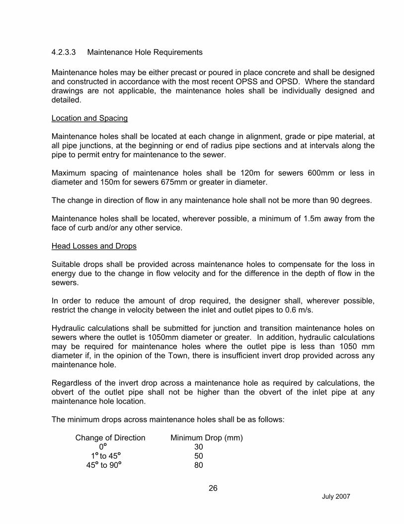
4.2.3.3 Maintenance Hole Requirements
Maintenance holes may be either precast or poured in place concrete and shall be designed and constructed in accordance with the most recent OPSS and OPSD. Where the standard drawings are not applicable, the maintenance holes shall be individually designed and detailed.
Location and Spacing
Maintenance holes shall be located at each change in alignment, grade or pipe material, at all pipe junctions, at the beginning or end of radius pipe sections and at intervals along the pipe to permit entry for maintenance to the sewer.
Maximum spacing of maintenance holes shall be 120m for sewers 600mm or less in diameter and 150m for sewers 675mm or greater in diameter.
The change in direction of flow in any maintenance hole shall not be more than 90 degrees.
Maintenance holes shall be located, wherever possible, a minimum of 1.5m away from the face of curb and/or any other service.
Head Losses and Drops
Suitable drops shall be provided across maintenance holes to compensate for the loss in energy due to the change in flow velocity and for the difference in the depth of flow in the sewers.
In order to reduce the amount of drop required, the designer shall, wherever possible, restrict the change in velocity between the inlet and outlet pipes to 0.6 m/s.
Hydraulic calculations shall be submitted for junction and transition maintenance holes on sewers where the outlet is 1050mm diameter or greater. In addition, hydraulic calculations may be required for maintenance holes where the outlet pipe is less than 1050 mm diameter if, in the opinion of the Town, there is insufficient invert drop provided across any maintenance hole.
Regardless of the invert drop across a maintenance hole as required by calculations, the obvert of the outlet pipe shall not be higher than the obvert of the inlet pipe at any maintenance hole location.
The minimum drops across maintenance holes shall be as follows:
Change of Direction Minimum Drop (mm) 0o 30 1o to 45o 50 45o to 90o 80

July 2007
27
Frame and Grate
All maintenance hole covers shall be as per OPSD 401.01 with Type A closed cover.
4.2.3.4 Catchbasin Requirements
Catchbasins may be either precast or poured in place and shall be designed and constructed in accordance with the most recent OPSD and OPSS requirements.
Location and Spacing
Catchbasins shall be selected, located and spaced in accordance with the conditions of design. The design of the catchbasin location and type shall take into consideration the lot areas, the lot grades, pavement widths, road grades and intersection locations.
Maximum spacing for catchbasins including cul-de-sac gutters shall be as follows: � Road grade 0.5% to 3.0% - 110m � Road grade 3.1% to 4.5% - 90m � Road grade greater than 4.6% - 75m
Catchbasins shall be generally located upstream of pedestrian crossings. Catchbasins shall not be located in driveway curb depressions.
Catchbasins Types
Typical details for single, double and rear lot type catchbasins are shown in the OPSD.
Any special catchbasins and inlet structures must be fully designed and detailed by the Engineer for approval by the Town.
Double catchbasins are to be installed at the low point or sag of any road.
Catchbasin Leads
For single catchbasins the minimum size of connection shall be 250mm and the minimum grade shall be 2.0%. For double catchbasins, including rear lot catchbasins, the minimum size of connection shall be 300mm and the minimum grade shall be 2.0%.
In general, catchbasins located in close proximity to a downstream maintenance hole shall have their leads connected to the storm sewer. Long catchbasin connections (in excess of 20m) shall be connected to a maintenance hole.

July 2007
28
Frame and Grate
The frame and cover for catchbasins in roadway or walkway areas shall be as detailed in the OPSD 400.02. Catchbasins located within the traveled portion of a roadway shall have the frame elevation set flush with the surface of the base course asphalt. The adjustment and setting of the frame and cover shall be completed in accordance with the details provided in the OPSD 704.010. Catchbasins located in grassed areas shall have the Birdcage Grate per OPSD 400.120.
4.2.3.5 Roof Leaders, Foundation Drains and Storm Connections
Roof Leaders
Roof leaders shall not be connected directly to the Town sewer systems. Leaders shall discharge to concrete splash pads in landscaped areas and directed to side yard swales.
Foundation Drains
It is the Town policy that foundation drains shall not be connected directly to the Town sewer systems. A sump pump system shall discharge to a 100mm residential storm sewer connection. Where storm sewer connections are not available, the sump pump system shall discharge to a concrete splash pad in a landscaped area and with the water directed to side yard swales. The geotechnical report shall consider the ground water table elevation and recommend minimum basement elevations. Foundation drain discharge water that becomes a nuisance shall be corrected.
Storm Connections
All newly proposed residential developments will be required to provide a storm sewer connection to all residential dwellings. The residential storm sewer system will be oversized to accommodate these additional flows.
The Geotechnical report will need to consider seasonal high water level or other ground water issues in addition to finished lot grading prior to recommending a deviation from the above mentioned policy.
Residential storm connections shall be PVC 100mm SDR28 colour white.
Residential storm connection shall terminate at 1.0 m right of sanitary connection (when facing lot) with a gasketed cap/plug and an 89 mm x 38 mm marker painted white.
4.2.3.6 Channel, Culvert and Overland Flow

July 2007
29
For channel, culvert, bridge and/or erosion control projects the proponent is responsible for obtaining all necessary approvals from the governing agencies, such as the NVCA, MNR, DFO and/or MOE.
4.2.3.7 Culverts and Bridges
Road Classification Design Flood Frequency
Arterial 1:100 Year to Regional Collector 1:50 Year Urban Local 1:25 Year Rural Local 1:25 Year Temporary Detour 1:10 Year Driveway 1:5 Year
Headwalls are required on driveway culvert ends where road speed is 50 km/hr or less. For roads exceeding 50 km/hr all culverts must be of sufficient length to provide for a minimum 5:1 slope off the driving surface to the ditch invert. All driveway culverts require entrance approval.
Bridges and other major drainage structures shall require special designs as determined by the Town. Hydraulic calculations will be required.
The frequency and magnitude of flooding or erosion shall not be increased on upstream or downstream properties.
4.2.3.8 Open Channels
The proposed criteria for an open channel design shall be submitted to the Town for approval prior to the actual design being undertaken. Open channels shall be defined as major system overland flow channels, minor system outfall channels or natural channels. Major system overland flow channel designs may be required to accommodate the Regional storm or the 100-year storm for new development.
“Natural” channel design criteria will be determined on a site by site basis. The following guidelines must be considered:
Open Channels Minimum Velocity Maximum Velocity
Grass lined - Natural 0.7 m/s 1.5 m/s Grass lined - Maintained 0.7 m/s 1.5 m/s Gabion lined 0.7 m/s 2.5 m/s Concrete lined 0.7 m/s 4.0 m/s

July 2007
30
4.2.3.9 Watercourse Erosion and Bank Stability
Where erosion or bank instability is already evident in an area to be developed or re-developed, the Town of Collingwood requires that the situation be stabilized by appropriate remedial measures. Where development will cause significantly increased downstream erosion, the Town also requires the Developer to mitigate further damage by appropriate remedial measures.
Where designing remedial erosion or bank stabilization works, preservation of the watercourse dynamics and natural valley aesthetics must be secondary only to achieving a sound technical solution. The proposed design shall reference the MNR Natural Channel Design Manual. A normal bank flow channel has a capacity of about the 1:2 year flood. Protection to this level will be adequate provided care is taken to prevent any damage by higher floods and provided that the channel bank is not coincident with a higher valley bank. In this latter case, it may be necessary to protect the bank to a level as high as the 1:100 year flood or even the flood resulting from the Regional Storm.
The proposed criteria for an erosion or bank stability design shall be submitted to the Town for approval prior to the actual design being undertaken.
4.2.3.10 Overland Flow Routes
An overland flow route continuous to the nearest major channel must be established through all areas and shall be contained within either the road right-of-way or by easements.
The depths of flooding permitted on streets and at intersections during the 1:100 year storm are as follows:
� no building shall be inundated at the ground line, unless the building has been flood proofed;
� for all classes of roads, the depth of water at the gutter shall not exceed 0.3m.
Flow across road intersections shall not be permitted for minor storms (generally 1:10 year). To meet the criteria for major storm run-off, low points in roads must have adequate provision for the safe overland flow.
4.2.3.11 Inlet/Outlet Structures
Inlet and outlet structures shall be fully detailed on the engineering drawings. The details provided shall include the existing topography, proposed grading and the works necessary to protect against erosion.
Adequate means such as gabion baskets, rip-rap or concrete shall be provided at all inlets to protect against erosion and to channel the flow to the inlet structure and at all outlets to prevent erosion. The extent of the erosion protection shall be indicated on the engineering

July 2007
31
drawings and shall be dependent upon the velocity of the flow in the storm sewer outlet, the soil conditions, the flow in the existing watercourse and site conditions.
The inlets and outlets must be protected to prevent unauthorized access and debris accumulation.
Outfall structures to existing channels or watercourses shall be designed to minimize potential erosion or damage in the vicinity of the outfall from maximum design flows.
The obvert of the outlet pipe is to be above the 25 year flood elevation of the receiving channel.
4.2.3.12 Stormwater Management Ponds
When designing a stormwater management pond, the aesthetic development criteria of the pond design shall incorporate the facility as an amenity with features such as enhanced trail requirements, natural building materials and signage in addition to corresponding to the general guidelines provided by the Ministry of the Environment entitled “Stormwater Management Practices Planning and Design Manual - 2001”. Specifically, the design of stormwater management ponds shall be completed with consideration of the following aesthetic and landscape design criteria:
� Stormwater management dry ponds shall be designed to limit the maximum depth of water to 1.8 m above the lowest point of the stormwater basin. An additional 0.3 m freeboard is required above the maximum peak flow flood level. The maximum depth of the extended detention zone shall not exceed 1.0 m above the lowest point of the pond.
� Maximum side slope will be 5:1 from the bottom of the dry pond to the limit of maximum extended detention, with a minimum horizontal length of 3.0 m. The minimum allowable gradient on the bottom of the basin shall be 1.0% and the maximum gradient shall be 5%.
� Stormwater management wetlands shall be designed to limit the maximum depth of water to 2.1 m above the lowest point of the stormwater basin excluding micropools. An additional 0.3 m freeboard is required above the maximum peak flow flood level. The maximum depth of the extended detention zone shall not exceed 1.0 m above the permanent pool elevation. Maximum peak flow attenuation zone shall not exceed 1.8 m above the permanent pool elevation. The permanent pool depth shall range between a minimum depth of 0.15 m to a maximum depth of 0.45 m.
� A maximum 5:1 slope below the permanent pool level shall be permitted around the entire stormwater management wetland. A maximum 5:1 slope above the permanent pool level shall be permitted around the entire stormwater management wetland. The slope shall extend from the permanent pool level, to the limit of maximum extended detention. The horizontal distance of this slope must be a minimum of 3.0 m.

July 2007
32
� Stormwater management wet ponds shall be designed to limit the maximum depth of water to 3.3 m above the lowest point of the stormwater basin. An additional 0.3 m freeboard is required above the maximum peak flow flood level. The maximum depth of the extended detention zone shall not exceed 1.0 m above the permanent pool elevation. The permanent pool depth shall range between a minimum depth of 1.0 m to a maximum depth of 1.5 m.
� A maximum 5:1 slope below the permanent pool level shall be permitted around the entire stormwater management wet pond. The horizontal distance of this slope must be a minimum of 3.0 m. A slope commencing from this point to the lowest point of the stormwater basin shall be a maximum of 3:1. A maximum 5:1 slope above the permanent pool level shall be permitted around the entire stormwater management wet pond. The slope shall extend from the permanent pool level to the limit of maximum extended detention. The horizontal discharge of this slope shall be a minimum of 3.0 m.
� Fencing of stormwater management facilities is not desired. However, fencing may be required if the Town considers it a safety issue. Where stormwater management facilities to be owned by the Town abut private property, fencing may be required at the discretion of the Town. At a minimum, demarcation of property boundaries is required. Fencing and/or property demarcation shall be to Town standards.
� In situations where existing natural areas are proposed to be used for stormwater management, exemptions to the depth and slope criteria may be provided to minimize disturbance to the natural feature, at the discretion of the Town of Collingwood.
� Designed pedestrian access areas shall not exceed a maximum slope of 6:1.
� Notwithstanding the above slope and depth criteria, in the case of headwall design, the depth of water related to adjoining side slopes may vary and fencing is required for safety purposes.
� Areas subject to the collection of contaminants or spills shall be fitted with adequate oil/grit separators.
� In the event that a community trail has been identified and/or required by the Town in the vicinity or adjacent to a storm water management pond, they shall be implemented above the maximum extended detention level or 5 year storm level, which ever is greater, in order to prevent frequent flooding. Trails shall have a minimum width of 3.0m.
� To enhance user comfort and safety, a 3.0m zone on each side of the community trail shall be designed in such a way that sightlines are preserved. If barriers are required, they must not interfere with visibility or create entrapment areas. In situations where a community trail is designed within the maximum peak flow depth zone, the 3.0m

July 2007
33
separation above the trail shall have a maximum slope of 3:1. Below the trail, the 3.0m separation shall have a maximum slope of 6:1. This zone shall be planted with low ground covers.
� Prior to the Department of Public Works accepting the storm water management pond as shown on the approved landscape plan, the Subdivider agrees to erect one or more information signs at (a) Public Access Points detailing the purpose of the pond, phone number for further information and any other relevant information.
� Maintenance access requirements are to be determined on a site-by-site basis, however, the following general criteria are recommended: Controlled maintenance access routes shall be provided to both inlet and outlet structures and forebays. A minimum 3.0 m wide surface to accommodate maintenance vehicles within a minimum 10 m turning radius (inside radius) and a flat 10 m loading areas is required. Maintenance access routes shall not exceed a maximum slope of 10:1. The design of maintenance routes and loading areas shall be to the approval of the Public Works Department.
� Structural materials utilised within the pond design must have regard for natural aesthetic principles (i.e. Armour Stone). Man made structures such as concrete headwalls, gabion baskets, and gabion rock are undesirable in pond designs.
4.2.4 Stormwater Quantity Control
Storm water management is required to control increases in storm runoff due to development. Typical methods of quantity control are temporary storage of water on flat roof tops and parking lots, discharging rainwater leaders onto grassed areas and downstream stormwater retention or detention ponds. Stormwater quantity controls are to be implemented on all applications in accordance with the applicable master drainage or subwatershed plan or site specific stormwater management plan.
4.2.4.1 Stormwater Management Requirements
The stormwater management requirements generally must reflect district solutions and vary depending upon the watershed, and in some cases the storm sewer shed, that the site is located. Site specific requirements can be obtained from the Town. A stormwater management report will be required for all development applications.
4.2.4.2 On Site Stormwater Management Reports
Where on site stormwater quantity controls are required, a stormwater management report addressing the points listed below must be submitted:
� the modified rational method, or equivalent, is to be used for the analysis;

July 2007
34
� a control device (orifice) must have a diameter of no less than 75mm in order to prevent clogging of the opening;
� storm connections from the building roof and foundation drains must be made downstream of the maintenance hole and/or catchbasin inlet controls;
� ponding limits and available storage are to be depicted on the site servicing drawings, and the maximum ponding depth in parking areas is not to exceed 250mm;
� an overland flow route shall be clearly marked on drawings. The grading of parking lots and landscaped areas must provide a safe path for the overland flow route to the surrounding municipal right of way during storms exceeding the design storm event;
� roof drains should be selected to give a minimum discharge of 0.042 cms/ha of roof area;
� details and concepts are to conform to the Urban Drainage Design Guidelines, set out by the MOE;
� all on-site storm water management requires a Certificate of Approval from the MOE. Two completed MOE Application forms are to be submitted to the Town signed by the developer and consultant;
� where applicable, approval will be required from NVCA; � a Professional Engineer must approve and stamp the on-site storm water
management report and site servicing drawings;
4.2.5 Stormwater Quality Control
Water Quality controls are to be implemented on applications in accordance with the applicable Master Drainage or Sub watershed Plan or site specific plan. A sub watershed plan for Black Ash Creek has been prepared by the Nottawasaga Valley Conservation Authority in association with the Town of Collingwood et al. In the absence of an established plan the MOE - Stormwater Management Practices, Planning and Design Manual should be used.
4.2.6 Hydrologic and Hydraulic Studies
Required hydrologic studies shall employ an appropriate modelling technique with defensible parameter values. The study shall describe the modelling parameters and the criteria for their selection as well as input and output data. The consultant is to assume full responsibility for the proper application of the hydrologic models. The Town recommends that the Consultant follow the MTO Drainage Management Technical Guidelines. To facilitate municipal review, the following documentation must be submitted.
1) Map showing the modelling sub catchments.
2) Summary tables that provide the following data on each modelling sub catchment: � total drainage area; � pre and post-development impervious area;

July 2007
35
� pre and post-development runoff coefficient to each ground cover element (rooftop, street, grass, etc.);
� total drainage area devoted to each hydrologic soil group; � storage volumes associated with pre and post-development runoff control measures.
3) Map showing the drainage areas with modelling parameters, proposed facilities and pre and post-development flows at all crossings.
4.2.7 Meteorology
The intensity-duration frequency curves used for the Town of Collingwood were originally derived from rainfall data taken from the Owen Sound Atmospheric Environment Services weather station. The equations for these curves are as follows:
2 Year Storm I= 807.44 (T.C.+6.75)0.828
5 Year Storm I = 1135.4(T.C. + 7.5) 0.841
10 Year Storm I = 1387(T.C. + 7.97) 0.852
25 Year Storm I = 1676.2(T.C. + 8.3) 0.858
50 Year Storm I = 1973.1(T.C. + 9.0) 0.868
100 Year Storm I = 2193.1 (T.C.+9.04)0.871
Based on these IDF curves, the Consultant is to develop the proper design storms for use in hydrologic studies.
In general, the SCS design storms should be used for determining the hydrographs for undeveloped watersheds and for checking detention storages required for quantity control. The Chicago design storms should be used for determining hydrographs in urban areas and also for checking detention storage. In many cases, the consultant will be required to run both sets of design storms to make sure that the more stringent is used for each individual element of the drainage system (pipe flow, street flow, channel flow, detention storage).
The time step for discretization of the design storm can vary according to the size of the sub-watershed, but must not exceed the estimated time of concentration. The maximum rainfall intensity should be compatible with that of real storms on record.

July 2007
36
4.3 Sanitary Sewer System
4.3.1 Sewer System
Sanitary sewers designed and constructed in accordance with the most recent requirements and specifications of the Town of Collingwood are required to carry domestic commercial and industrial sewage from each area of the subdivision under consideration. Flow is to be by gravity and pumping will be considered only where other alternatives are not possible and only with the approval of the Town.
(The Town commissioned a report entitled “Servicing Study for Lands Acquired Under County Restructuring in the Town of Collingwood” in 1994). Among other issues the report reviews the existing collection and treatment works, provides calculations of potential sewage flows from the newly acquired area and analyses the impact on the existing collection works and assesses options collecting and pumping sewage from the acquired areas.
4.3.2 Maintenance
The Developer shall maintain the complete sanitary sewer system including routine flushing for the duration of the maintenance period. The sanitary sewers will not be released from the maintenance period until assumption of the subdivision.
4.3.3 Sanitary Sewer Design
4.3.3.1 Design Flows
The sewers are to be sized for maximum design flows plus an allowance for infiltration. Maximum velocities and slopes are to be determined for maximum design flows without infiltration.
The average daily domestic flow is to be taken at 450 L/capita/day.
Equivalent domestic flows for areas intended for uses other than residential shall be calculated on an area basis and reviewed with the Town prior to design.

July 2007
37
Maximum design flows are to be determined using average daily flows and peaking factors.
A wet weather infiltration rate of 20,000 L/ha/day = 0.23 L/ha/s is to be used. To satisfy self-cleaning requirements in sanitary sewers assume dry weather infiltration reduces to zero for several days during dry months.
4.3.3.2 Sanitary Sewer Requirements
The system shall be designed to service all areas within the subdivision to their maximum future development in accordance with the Town’s Official Plan. Allowance shall be made for inflows from the appropriate adjacent subdivisions or areas and shall meet with the approval of the Town. Discharges of the system are to be into appropriate sewers and are to be approved by the Town. The exact location for connecting to sewers in adjacent subdivisions or areas shall be as approved by the Town.
Pipe Capacities
Manning’s formula shall be used in determining the capacity of all sanitary sewers. The capacity of the sewer shall be determined on the basis of the pipe flowing full. A roughness coefficient of n= 0.13 shall be used for all smooth wall types of pipe.
Flow Velocities
The minimum velocity for sewers operating partially full shall result in self-cleansing equivalent to that produced by flow in sewer operating full at a velocity of 0.6 m/s.
For circular pipes (flowing full) the minimum acceptable velocity is 0.75 m/s and the maximum acceptable velocity is 3.0 m/s
Pipe Grades
The maximum and minimum grades for pipes shall be the grade necessary to meet the maximum and minimum velocity requirements except that the required grade for the minimum velocity requirement shall not exceed 2% or the road grade where the road grade exceeds 2%.
Minimum Sizes
The minimum size for an on street sanitary sewer shall be 200mm.
Depth of Sanitary Sewers
Sanitary sewers shall be located a minimum of 1.0 m below basement floor elevations to allow for the installation of sewer laterals. In areas of no sanitary sewer connection the sewers shall have a minimum frost cover of 1.6m.

July 2007
38
Location
The sanitary sewers shall be located as shown on the standard Town of Collingwood road cross section drawings.
A minimum vertical separation of 500mm shall be provided between the obvert of the sanitary sewer and the invert of the storm sewer. The sanitary sewer connections are required to go under the storm sewer.
Limits of Construction
Sewers shall be terminated with a maintenance hole at the subdivision limits when external drainage areas are considered in the design. The design of the terminal maintenance holes must allow for the future extension of the sewer.
Sewer Alignment
Sanitary sewers shall be laid in a straight line between maintenance holes unless radius pipe has been designed. Joint burial (common trenching) with storm sewers will be considered when supported by the recommendations of a soils report prepared by a qualified Geotechnical Engineering.
Changes in Pipe Size
No decrease of pipe size from a larger upstream to a smaller size downstream will be allowed regardless of the increase in grade.
Standard Easement Requirements
The minimum width of easements for storm sewers shall be in accordance with the following guidelines:
Size of Pipe Depth of Invert Minimum Width of Easement
250 to 375mm 3.0 m maximum 4.0 m 450 to 675mm 3.0 m maximum 4.5 m 750 to 1500mm 3.0 m maximum 6.0 m 1650mm and up 4.0 m maximum 4.0 m plus 3 times O.D. of Pipe
For easements containing more than one pipe or underground service the minimum width will be based on the above chart for the maximum pipe size plus 3.0m.
Regardless of the preceding, all situations will be reviewed and judged on individual cases at the discretion of the Town.

July 2007
39
Pipe Material Classification and Bedding
Sanitary sewers shall be PVC. Concrete or HDPE may be considered in some applications. All sanitary sewer pipes shall conform to the requirements of CSA and OPSS.
For sewer applications requiring pressure pipe, pipe design should reference MOE guidelines.
The class of pipe and the type of bedding shall be designed to suit loading and proposed construction conditions. Details are illustrated in the OPSD standard Bedding and Backfill details. In general, Type “B” bedding (Granular A bedding with granular over the sewer) shall be used for sanitary sewers in new developments.
In areas where it is difficult to control the infiltration of ground water into the sewer trenches a clear stone may be used provided it is wrapped in a suitable geotextile, selected and installed in accordance with the manufacturer’s requirement.
The width of trench at the top of the pipe must be carefully controlled to ensure that the maximum trench width is not exceeded unless additional bedding or higher strength pipe is utilized.
Testing and Acceptance
The complete sewer system including service connections to the property line and maintenance holes shall be tested in accordance with OPSS. Deflection testing test as per OPSS is required on all pipe works prior to substantial performance. All pipe works shall have a CCTV inspection as per OPSS 409 complete as part of the substantial performance and final acceptance inspections.
4.3.3.3 Sanitary Maintenance Hole Requirements
Maintenance holes may be either precast or poured in place concrete and shall be designed and constructed in accordance with the most recent OPSS and OPSD. Where the standard drawings are not applicable, the maintenance holes shall be individually designed and detailed.
Location and Spacing
Maintenance holes shall be located at each change in alignment, grade or pipe material, at all pipe junctions, at the beginning or end of radius pipe sections and at intervals along the pipe to permit entry for maintenance to the sewer.
Maximum spacing of maintenance holes shall be 120m for sewers 600mm or less in diameter and 150m for sewers 675mm or greater in diameter.

July 2007
40
Maintenance Hole Details
Maintenance holes shall be designed as follows: � the change in direction of flow in any maintenance hole shall not be more than 90
degrees;� where the difference in elevation between the obvert of the inlet and outlet pipes
exceed 0.9 m, a drop pipe as indicated on OPSD 1003.010 shall be placed on the inlet pipe;
� all maintenance holes shall be benched as per OPSD 701.021; � maintenance holes shall be located, wherever possible, a minimum of 1.5m away
from the face of curb and/or any other service; � all maintenance holes shall have frost straps as per OPSD 701.100; � all connections to maintenance holes shall have rubber boot pipe connection; � safety platforms shall be provided as per OPSS; � safety chains shall be provided on the downstream side of maintenance holes for
sewers larger than 1.2m.
Head Losses and Drops
Suitable drops shall be provided across maintenance holes to compensate for the loss in energy due to the change in flow velocity and for the difference in the depth of flow in the sewers.
In order to reduce the amount of drop required, the designer shall, wherever possible, restrict the change in velocity between the inlet and outlet pipes to 0.6 m/s.
Regardless of the invert drop across a maintenance hole as required by calculations, the obvert of the outlet pipe shall not be higher than the obvert of the inlet pipe at any maintenance hole location.
The minimum drops across maintenance holes shall be as follows:
Change of Direction Minimum Drop (mm) 0o 30 1o to 45o 50 45o to 90o 80
Frame and Grate
Where maintenance holes are located in areas to be flooded by the major design storm, maintenance hole covers shall be of the sealed variety and the maintenance hole is to be suitably vented.
All other maintenance hole covers shall be as per OPSD 401.01 with Type A closed cover.

July 2007
41
4.3.3.4. Sanitary Connections
Sanitary Connections
Sanitary connections are to be sized in accordance with the following sizes:
Single family residential: � single 125 mm diameter (min.) PVC SDR 28, green colour
Multiple family residential block, institutional, commercial and industrial blocks: � designed in accordance with Section 4.3.3.2.; � Min. size 200 mm diameter, green colour
Sanitary connections shall be in accordance with the following Standards: � OPSD 1006.010 Sewer Service Connection for Rigid Pipe; � OPSD 1006.020 Sewer Service Connection for Flexible Pipe.
Residential connections shall terminate 2.5 m right of water service (facing the lot) with a gasketed cap, 125 mm x 100 mm reducer, plug suitably braced to withstand test pressures and 89 mm x 38 mm marker placed from the invert of the connection to 600 mm above grade painted green.
Joints and Bedding:
Joints and Bedding for connections are to be equivalent to joints and bedding as specified for sanitary sewer pipe.
4.4 Water Supply System
4.4.1 Watermains
Watermains designed and constructed in accordance with the most recent requirements and specifications of the Town of Collingwood are required on every street within all proposed plans of subdivision. Watermains shall be of adequate size to provide service for the development of adjacent lands designated by the Town.
The Town commissioned a report entitled “Servicing Study for Lands Acquired Under County Restructuring in the Town of Collingwood” in 1994. Among other issues, the report reviews the existing water supply, distribution and storage system, assesses the additional water supply and storage works which might be required to service the acquired lands and summarizes the trunk watermains required within the acquired lands.
This specification is applicable to installation of services and watermains up to and including 400 mm in diameter. Installations of watermains larger than 400 mm in diameter or for any special installation shall be reviewed on an individual basis by the Town.

July 2007
42
4.4.2 Maintenance
The watermain system shall be maintained as required by regulation by CPU at the developer’s cost until assumption of all services in the subdivision. It should be noted that once the watermain has been tested and approved, only CPU can operate the system.
4.4.3 Watermain Design
4.4.3.1 Design Criteria
The proposed development must be serviced from the existing municipal water distribution system. The Developer shall provide and construct at his own cost a watermain suitable for supplying the entire project and interconnected where possible, the connection from the nearest 150 mm diameter or larger watermain, including any necessary easements, to the satisfaction of Collingwood Public Utilities. Abutting private owners may connect to this connecting watermain without charge by the Developer.
In order to provide proper and reliable water distribution systems within the development, reasonable looping of these systems shall be provided to the satisfaction of the Town. Permanent dead ends, such as on cul-de-sacs, are to be avoided.
All water testing and watermain chlorination will be conducted by CPU at the Developer’s cost. It should be noted that watermains are not to be connected to existing watermains until bacteriological testing has been successfully completed. The drawing STD No. 128 shows a typical temporary connection detail for new watermains. It should also be noted that if the developer intends to phase the servicing this type of detail will need to be incorporated at each phase connection point.
Should the Developer/Owner propose to “phase” the servicing of this development, the Town reserves the right to comment and/or alter the proposal, in order to service the development in a logical order.
Watermains shall be designed to accommodate the development. Watermain size shall be determined by fire flow plus maximum day use. Fire flows shall meet the following criteria: Flows to be calculated using typical hydrant flow calculations found herein.
a) Residential Single Family Streets: minimum 57 I/sec (750 gpm) @ 138 kpa residual (20 psi); preferred 76 I/sec (1000 gpm) @ 138 kpa residual (20 psi).
b) Institutional/Convenience Commercial: minimum 91 I/sec (1200 gpm) @ 138 kpa residual (20 psi); preferred 114 I/sec (1500 gpm) @ 138 kpa residual (20 psi).
c) Industrial/Commercial Subdivisions: minimum 136 I/sec (1800 gpm) @ 138 kpa residual (20 psi); preferred 152 I/sec (2000 gpm) @ 138 kpa residual (20 psi).

July 2007
43
d) Downtown Commercial: minimum 136 I/sec (1800 gpm) @ 138 kpa residual (20 psi); preferred 189 I/sec (2500 gpm) @ 138 kpa residual (20 psi).
4.4.3.2 Flow Calculations
Hydrant Flow
Typical Hydrant Flow Calculations:
Calculate flow at 20 P.S.I. Residual Pressure
QA = QT htha
QA = Flow at 20 P.S.I.
QT = Flow at Test
ha = Pressure Drop Available
ht = Pressure Drop Test
Example: Static - 56 PSIG; Residual - 40 PSIG; Flow - 976 GPM
QA = 976 40562056
��
= 1464 GPM
Design Flows
Watermains shall be designed to carry maximum day demand plus fire flows based on the latest publication of the Public Fire Protection Survey, or peak hour flow whichever is greater.
The average daily demand is to be taken as 450 litres/capita/day.
The estimated populations and areas for the different neighbourhoods shall be in accordance with the Official Plan.
The maximum day and peak hour factors shall be determined from the current MOE design guidelines although the following are considered minimums:
- Maximum daily demand factor: 2.0 - Peak hourly demand factor: 4.5

July 2007
44
Peak flows, other than domestic flows shall be determined on an individual basis.
4.4.4 Watermain Requirements
Selection of Main Sizes and Pressures
The Hazen-Williams formula (V= 0.85 C R 0.85 SH 0.54) shall be used for computing friction losses and subsequently sizing the watermains.
For new mains the values of “C” coefficient shall be 120 for 150 mm diameter pipe and 110 for 200 mm diameter pipe regardless of pipe material.
The minimum size of mains shall be 150 mm in diameter in residential subdivisions and 200 mm diameter industrial developments.
The minimum pressure during the peak hourly demand shall be 275 kPa.
The maximum pressure under static load or during the minimum hourly demand shall be 550 kPa.
The minimum fire flow in a residential area is to be 38 litres per second and the minimum fire flow in an industrial area is to be 75 litres per second. Watermains are to be sized accordingly.
The minimum pressure when the system is tested for fire flow in conjunction with the design maximum daily demand shall be 140 kPa.
A hydraulic network analysis of a water distribution system shall be carried out if design flow rates result in excessive head losses and main sizes greater than the minimum specified (150 mm) main sizes or when requested by the Town. Hydraulic analysis shall include allowances for demands of adjacent areas anticipated to be met by transmission through the design area.
In addition, the proposed water distribution system will require inclusion in the Town’s overall hydraulic network analysis. This work is to be carried out by CPU’s consultant at the Developer’s cost. CPU’s consultant will require digital plans showing the proposed distribution system and finished ground elevation in order to undertake this work.
Minimum Size
The minimum size for watermains shall be 150 mm. The Town may require larger mains in certain locations for circulation or other reasons and this cost shall be borne by the developer.

July 2007
45
Depth of Watermains
The minimum ground cover on watermains service laterals and hydrant leads shall be 1.7 m at all points.
Separation of Watermains and Sanitary Sewers
Minimum separation between watermains and sanitary sewers shall be provided in accordance with MOE guidelines.
Location
The watermain shall be located as shown on the Town of Collingwood standard road cross section drawings.
Extra Mains and Extra Fittings
No roadway leading out of the subdivision shall be completed and accepted by the Town until connecting watermains are installed complete to the subdivision limits.
Extra fittings shall be installed at any point on the watermains requested by the Town to provide for future connections.
Pipe Classification and Bedding
Watermains shall be class 52 or pressure class 350 cement lined ductile iron pipe as approved by the Municipality. Tracer wire shall be installed if continuity of pipe is broken. Tracer wire must be 12 AWG TWH solid plastic covered, TW4 75°C 600V or approved equivalent. A continuity test must also be completed and accepted.
Pipe bedding and cover shall be as per OPSS and OPSD.
Thrust blocks shall be required where pipe is placed in undisturbed native soils or where minimum soil bearing capacity exceeds 200 kPa. Where soil conditions are suspect, pipe restrainers shall be used.
Corrosion Resistance
The geotechnical report shall test the native material to determine soil corrosivity and comment on the requirement for corrosion resistance measures.
Fire Hydrants

July 2007
46
Fire hydrants shall be Canada Valve, Century No. 1 open left with 2 CSA hose ports, one 33 B pumper port and a break away type 6” MJ base. The hydrant lead shall be minimum 150 mm with resilient seated gate valve shut off “Open Left” by Clow or Meuller. The hydrants shall be self draining and installed as per OPSD 1105.010.
Hydrants are to be 1.85m (5’6”) long. Sections may be added if required to be installed below 1.85m section.
Hydrants shall be spaced at a maximum distance of 90 m in residential, commercial or industrial areas.
Wherever possible hydrants shall be located on the projection of side lot lines. A hydrant shall be placed at the end of every cul-de-sac and dead end street as well as at the high points in roads.
All hydrants shall be painted yellow with silver ports and bonnets. All hydrants shall have a Flexstake Hydrant Marker Model FHV804, 48" long, yellow in colour with a reflective hydrant graphic on both sides at the top of the marker. The required hydrant marker is positioned on the right port as viewed from the street. All hydrants shall have a fire hydrant anti tamper device for Century hydrants colour coded blue.
Valves
Valves shall be resilient seat gate valves RSGV Mechanical Joint, open left Clow or Mueller. Valve boxes shall be 5-SL-48 sliding or approved equal with cap painted blue.
Generally gate valves shall be located on the projection of side lot lines at or near intersections as required for spacing. Generally 4 valves shall be placed at cross intersections and 3 valves at tee intersections, such that broken sections can be isolated without jeopardizing flow to other sections.
Where watermains are terminated pending future extension, a valve and 2 additional lengths of watermain with plug, blow-off and thrust block shall be installed.
Valves shall have a maximum spacing of 150 m for distribution watermains and 400 m for trunk supply mains.
Air valves shall be considered at high points of all watermains where possible, installed together with valves in valve chambers.
Drains shall be considered at low points of all watermains and where possible, installed together with valves in valve chambers.
Service Connections

July 2007
47
Service connections shall be 20 mm type K copper pipe. Residential connections terminate at the property line at the centre of the lot with the fittings listed below and a 89 mm x 38 mm marker from the invert of the service to 600 mm above grade painted blue.
Service connections for industrial, commercial, institutional or multiple dwelling use will be considered on an individual basis. Fire connections may be required for industrial, commercial, institutional or multiple dwelling lots.
Water service fittings shall be as follows:
Main stop - Cambridge Brass 201-A3H3 (AWWA thread by compression) Curb stop - Cambridge Brass 203-H3H3 (AWWA compression by compression) Service Box - Clow or Mueller #7 or #8 D-I with 24” stainless steel rod, cap painted blue
Fittings
All fittings shall be mechanical joint ductile iron to meet AWWA/ANSI C153/A 21.53 specification. Also all mechanical joints shall use Rolmac gripper ring restraining glands for pipes up to 300 mm and Sigma one lock restraining glands for pipes larger than 300 mm.
Testing and Acceptance
The complete water system including service connections to the property line and hydrants shall be tested in accordance with OPSS prior to acceptance of the system as substantially performed. The complete water system shall be disinfected in accordance with requirements of Ontario Regulation 459/00 for chlorination of potable water supplies and the satisfaction of the Town. All water used for testing will be metered or estimated, recorded and charged to the Developer.
4.5 Roadways
4.5.1 Road Works
Asphalt roadways complete with concrete curbs and gutters designed and constructed in accordance with the most recent requirements and specifications of the Town, OPSS and OPSD are required on all road allowances within the plan of subdivision. The geometric standard of the roadway shall be as stipulated in the Town Standards and Drawings and designated by the Town. The balance of the road allowance not occupied by the roadway, driveways, splash pad or sidewalks shall be graded and completely top soiled and sodded to the satisfaction of the Town.
Roadways with a rural, open ditch, cross section will only be considered for developments with large lot frontages (over 45 m) and where groundwater levels are proven to be well below proposed ditch grade and shall not be provided unless approved by the Town.
July 2007
48
4.5.2 Maintenance
Above ground works shall be guaranteed for a minimum period of one year after the issuance of preliminary acceptance of the top course asphalt. Notwithstanding the above ground works shall be maintained until assumption of all services in the subdivision.
4.5.3 Geometric Design
Roadway geometric design will be in accordance with the Town of Collingwood Geometric Design Standards and Road Sections as outlined on Town Standard Drawings No. 201 to No. 230
Road widths and Rights-of-Way will be in accordance with the most recent Town of Collingwood Standards.
1) Geometric Design Standards for Roads (STD 100) 2) Urban Local Residential (20.0 m ROW 8.5m Paved) (STD 201) 3) Rural Local Residential (20.0 m ROW 7.0m Paved) (STD 202) 4) Urban Local Divided Road (26.0 m ROW 2X6.0m Paved) (STD 203) 5) Urban Collector (26.0 m ROW 15.0 m Paved) (STD 205) 6) Local Industrial (26.0 m ROW 8.0 m Paved) (STD 206) 7) Minor Arterial Road / Industrial Collector (30.0 m ROW 16.0 m Paved) (STD 207) 8) Minor Arterial Road with Urban Trail (32.0 m ROW 16.0 m Paved) (STD 208) 9) Industrial Cul-de-sac (STD 220) 10) Residential Cul-de-sac (STD 221) 11) Temporary Cul-de-sac (STD 223) 12) Road Elbow Design (STD 224)
4.5.4 Driveway Entrances
Driveway entrances and curb cuts shall be in accordance with OPSD 350.010 and 351.010.
All new residential driveways shall be paved with 50 mm HL3A from curb to the property line on a base of a minimum of 150 mm granular ‘A’ or 150 mm of 19 mm crusher run limestone.
The minimum clear distance between the edge of driveway and a utility structure or hydrant shall be 1.2m.
Rural driveways shall include an entrance culvert unless the driveway is sited at a ditch highpoint. All rural driveways require an entrance approval permit.

July 2007
49
4.5.5 Special Road Designs
Special road designs, which are not covered by Town of Collingwood Standards, shall be in accordance with the most recent provisions of the geometric design standards manual and urban street geometrics, as adopted by the Municipal Engineers Association. i.e. Special Design will be required in high density residential, commercial and industrial areas.
4.5.6 Pavement Design (Roadways)
Pavement design shall be completed by the geotechnical consultant in accordance with the most recent Town of Collingwood Standards, OPSS and OPSD.
Tests of subgrade materials must be conducted by a recognized soils laboratory and be acceptable to the Town. Copies of tests, along with proposed road designs, shall be submitted to the Town. Minimum thickness of asphalt and granular material shall be as indicated on Town Standard Drawings in all cases:
� base course asphalt shall be O.P.S.S. HL8. with a minimum insitu A.C. content of 4.5%;
� the wearing course of asphalt shall be: - for Local Roads, Collector Roads and Industrial Roads - O.P.S.S. H.L3; - for Arterial Roads O.P.S.S. H.L3. � O.P.S.S. Granular ‘A’ and Granular ‘B’ materials are most commonly used for road
construction in the Town of Collingwood. The Town will consider crushed products with the following provisions: - where roadways which contain four or more paved lanes, the curb lane roadway
pavement specification shall be increased as follows: - the binder course (base) asphalt under the bus route or curb lane must be
increased by 50 mm; - on four lane roadways and bus routes, the base course asphalt shall be HDBC
(OPSS 1149).
4.5.7 Top Course Asphalt
Approval to place top asphalt is required from the Town Engineer. The following must be completed:
� building permit to be issued for minimum 80% of all lots; � all sidewalk, curb and boulevard work; � raise maintenance hole and catchbasin frames; � install delineation for raised frames 40 mm above asphalt lift; � flush and sweep surface and evenly apply tack coat on full width; � base course asphalt pad as required in accordance with OPSS;

July 2007
50
� final sewer video inspection; � place top course asphalt in accordance with OPSS.
4.5.8 Curbs and Gutters
New Town streets shall be constructed with curb and gutter as per OPSD 600.04 (Barrier Curb with Standard Gutter) or OPSD 600.07 (Barrier Curb with Standard Gutter-Two Stage) and OPSS 353. The Town prefers two stage curb. Mountable curb (OPSD 600.100) may be considered acceptable on low volume local streets at the discretion of the Town. Prior to final acceptance all curb blemishes will be rectified by removing a minimum 1 m section of curb and replacing.
A driveway entrance is required for each lot. Curb depressions are required at each intersection as per OPSD 310.030.
A minimum of 300 mm of Granular ‘B’ material compacted to 95% Standard Proctor Density will be required as a base for all curb installations.
Minimum grade on curb is 0.75% desirable, 0.5% absolute minimum.
Driveway entrances are not permitted in conjunction with the use of the Urban-Local divided road Std. No. 203
4.6 Street Name And Traffic Signs
4.6.1 Plan
The above ground plan shall show the proposed location of signs to be installed in the subdivision. The plan shall be part of the engineering drawings, which must be approved by the Town. The signs must be clearly shown without cluttering other details.
4.6.2 Street Signs
Street name signs shall be placed at every intersection and shall be double sided. These signs shall be placed in the locations and shall be of the type shown on Town Standard Drawing. Street name and traffic signs shall be supplied and erected by the Developer.
Temporary regulatory signs must be reflective. All permanent signs must be to Town Standard.
Unassumed road signs (Use at own risk) are to meet following requirements
� Black lettering on Yellow reflective backing

July 2007
51
� 60cm wide by 90cm tall � Located on street post
Traffic control signs shall conform to the most recent versions of the Ontario Traffic Manual or the Highway Traffic Act Regulations for Ontario.
Signs are to be aluminum, anodized both sides, according to the following requirements: Sizes Material
600 mm - 1.6 mm utility series 600 mm - 900 mm - 2.0 mm No. 655T6 over 900 mm - 3.2 mm No. 655T6
All traffic control signs are to be made with high intensity type reflective sheeting approved by the Ministry of Transportation Ontario, the current standards of the Ontario Traffic Manual, the Highway Traffic Act Regulation for Ontario and The Town Engineer, including colours.
4.7 Roadway Markings
The Developer will design pavement markings for all roadways over two lanes in width or as required by the Town. The design shall be in accordance with the Ontario Traffic Manual and approved by the Town. These pavement markings will be installed on the top coat of asphalt and in some circumstances on the base coat of asphalt. The Developer shall be responsible for stop bars on roadways that are up to two lanes in width. All Roadway markings shall be installed in accordance with OPSS 532.
4.8 Traffic Signals
Traffic Signals are to be designed on individual site-specific bases.
4.9 Streetlighting
Streetlights are to be designed by an Electrical Consultant and installed along all streets and most public walkways in accordance with the most recent lighting requirements and standards of the Town of Collingwood. Electrical work is to be designed and constructed in accordance with the most recent requirements and specifications of the Town and COLLUS.
Approval by Collingwood Public Utilities is required before any street lighting will be assumed into the Town’s streetlight inventory. The Developer must guarantee and maintain the lighting until Final Acceptance. Energy charges will be paid by the Town upon energization of the street lighting, but not until the first occupancy has occurred. If the

July 2007
52
development wishes to energize the lights before the first occupancy, arrangements must be made with COLLUS for payment of energy charges.
4.9.1 Lighting Levels and Uniformity Ratio
Streetlighting shall be supplied and installed on all streets and pedestrian walkways in the subdivision.
Road Classification (ROW/Pavement) Illumination Level / Uniformity Ratio
Residential 20m/8.5m 2 Lux/6:1 Urban Collector 26m/14.5m 6 Lux/3:1 Minor Arterial, Ind. Collector 30m/16.0m 9 Lux/3:1 Walkways 2 Lux/6:1
Estate Residential development lighting shall be based on an average pole spacing of 100 meters.
4.9.2 Light Source
The light source shall be High Pressure Sodium or for certain applications and with site specific approval, metal halide. Minimum wattage of lights shall be 100 watts and all intersections must have a light located at the intersection with a wattage a minimum 50 watts higher that the main street wattage.
4.9.3 Light Fixture and Pole
The light luminaire and pole shall be as approved by the Town Engineer and in accordance with Town Standard drawing. Architectural style luminaries and poles will be considered on a case by case basis. The Town reserves the right to limit the number of alternative styles and types within the Town.
4.9.4 Approval and Construction
Approval of plans for streetlighting must be obtained from the Town. The Developer must guarantee and maintain the lighting until final acceptance of the development. The Town, upon energization of the streetlighting, will pay energy charges.

July 2007
53
4.10 Pedestrian Ways
4.10.1 Sidewalks and Walkways
Where the development generates the need, in the opinion of the Town, sidewalks may be required on existing streets external to the Subdivision or streets where reverse frontage is proposed.
Walkways shall be constructed as required within the plan for the proper circulation of pedestrian traffic and shall be in accordance with the most recent requirements and specifications of the Town. All walkways shall be contained within Blocks, generally 3.0m wide, deeded to the Town. Walkway Blocks may be located within larger service easements.
4.10.2 Location
Sidewalks shall be constructed as shown on the Town’s Road Cross-Section Standards. Streetlight poles should be located on the same side as the sidewalk. Local roads shall have, as a minimum, a sidewalk constructed on one side of the right-of-way and Arterial/Collector Roads shall have sidewalk on both sides. The requirement for sidewalks may be deleted at the discretion of the Town on short, low volume local roads (cul-de-sacs and crescents) on a site specific basis.
4.10.3 Specification
Sidewalks shall be constructed according to OPSD 310.010, 310.020, 310.030, 350.010, 351.010 and OPSS 351. Concrete sidewalks shall be placed on a minimum 150 mm compacted granular A base.
4.10.4 Trailways
The Developer may be required to design and construct a trail system, walkways and linkages to existing trail systems. Trail developments will be implemented according to Town standards. All trail and walkway developments shall be shown on the landscape plans.
The minimum standard for the multi-use urban trail shall be:

July 2007
54
� 3.0 m width, of 150 mm concrete; � 30 MPa with 6-8% entrained air; � 6x6 6Ga welded wire mesh; � 200 mm granular A base compacted to 95% SPDD; � broom finish with tooled edges and control joints.
4.11 Fencing
Fencing shall be in accordance with the most recent requirements and specifications of the Town as shown on the standard drawings.
Fencing is required: � along side yard flankage and/or rear yards backing onto roadways unless noise
attenuation barriers are required (in accordance with Town Standard 502); � along public walkways (In accordance with Town Standard 501); � parks, ponds and open space blocks (in accordance with Town Standard 501); � adjacent to commercial, industrial or institutional land uses where privacy is required
in accordance with Town Standard 502 or 504); � as designated by the Town Engineer; � acoustic fencing per approved report.
The minimum requirement for residential chain link fence is 1.5m high and screen fencing is 1.8m.
4.12 Residential Lot Drainage And Sodding
4.12.1 General
All lot drainage shall conform to the Stormwater Management Report and Town standards. The Developer shall be responsible for the grading of lots.
The Developer and his Consultant shall be responsible for approval and certification of the following for each lot:
� certification that the lot grading plan conforms to the storm drainage plan. Plan and certificate are to be submitted with the building permit application;
� certification that the final footing and top of foundation are in conformance with the certified grading plan (Tolerance 100 mm);
� certification of the final grading for each lot conforms to the storm drainage plan and lot grading plan.

July 2007
55
4.12.2 Lot Grading Criteria
The lot grading shall provide for the following:� rear to front lot grading is preferred and a maximum of three rear lots shall outlet
between any two lots; � rear lot catchbasins shall be eliminated wherever possible; � maximum number of lots drained by a rear lot CB shall be 5 lots in a row; � where rear lot catchbasins are used all structures shall be protected from flooding if
the inlet is blocked or surcharged by a major storm event; � maximum ponding depth for drainage swales is 0.35 m. � where several lots drain through a swale to a rear lot catchbasin on private property,
an easement shall be provided for the CB and lead; � minimum slope for swales shall be 2.0%; � a minimum of ¾ of the rear yard shall be graded at 2% - 5% slope; � each lot shall have at least one side yard with a maximum slope of 2% for 1.0 m
continuous width from front to rear yard; � maximum slope between houses shall be 4:1; � driveways shall have minimum 2% and maximum 6% slope; � grade around houses shall be a minimum of 2% away from houses from a point 200
mm below top of foundation wall or as required by OBC. � a maximum of three rear lots may drain overland to a boulevard before a rear lot
catchbasin (RLCB) can be used.
4.12.3 Sodding
The subdivision shall be sodded according to the following: � all lots shall be sodded using 100 mm top soil and No. 1 nursery sod from the street
line to the rear building line; � all swales, drainage easements, slopes greater than 10% and septic tile beds shall
be sodded using 100 mm top soil and No. 1 nursery sod; � all other areas of residential lots shall have a minimum of 100 mm top soil and seed
with variety and coverage approved by the Town; � where the combined side yard between buildings is less than 1.5 m the surface
treatment shall be 75 mm of clear stone over a vegetation suppressing geotextile.
4.12.4 Retaining Walls
Retaining walls shall be constructed according to the following: � where retaining walls are required they shall be constructed on the higher lot such
that the wall and tie-back do not cross property lines; � retaining wall design and construction shall be certified by the Engineer;

July 2007
56
� retaining walls shall be constructed on private property, not on property to be assumed by the Town.
4.13 Block Grading
All block grading shall conform to the storm water management report. The Developer shall be responsible for the grading of blocks until assumption of the subdivision. The Developer and his Consultant shall be responsible for approval and certification of the following:
� certification that the block grading plan conforms to the storm drainage plan. The block grading plan and certification shall be submitted with the building permit application;
� certification of the final grading for each block conforms to the storm drainage plan and the block grading plan.
4.13.1 Block Grading Criteria
The criterion for block grading is as follows: � rear to front block grading is preferred; � where catchbasins are used for block drainage all buildings and structures shall be
protected from storm water if the inlet is blocked or surcharged by a major storm event;
� where block drainage is surcharged to an existing overland flow route the route shall be protected from erosion;
� no more than 5% of the block surface area shall drain directly into the abutting road allowance;
� minimum slope for swales shall be 2%; � maximum ponding depth for swales shall be 0.35 m.
4.13.2 Ground Cover
The requirement for block ground cover is as follows: � all blocks shall be sodded using 100 mm topsoil and No. 1 nursery sod for 5 m width
around their perimeter when base course asphalt is placed, the remainder of the block shall be at minimum seeded using 100 mm topsoil, with seed of the quality and quantity approved by the Town, and mulch;
� the Developer shall be responsible to maintain the block until a building permit is granted, or in the case of blocks to be deeded to the Town, until the subdivision is assumed;
� all swales, drainage easements and slopes greater than 10% shall be sodded using 100 mm topsoil and No. 1 nursery sod.

July 2007
57
4.14 Erosion And Sediment Control
4.14.1 General
All erosion and sediment controls are temporary measures constructed prior to any other site work, and shall be maintained until assumption of the subdivision. Prior to assumption of the subdivision all temporary measures shall be removed and any disturbed areas stabilized.
All erosion and sediment control measures shall be inspected by the Consultant once per week and after each rainfall of 1cm or greater. Inspection reports shall be forwarded to the Town Engineering department within 5 days of inspection.
Erosion and sediment control measures shall be designed in accordance with Provincial guidelines.
4.14.2 Catchbasin Sediment Control
The requirement for catchbasin sediment control is as follows: � during construction, all catchbasins shall be provided with sediment control and this
shall be maintained until assumption;� catchbasins shall be cleaned as a minimum at least once before base course asphalt
is applied and just prior to assumption of the subdivision.
4.14.3 Stone Pad Construction Entrance - Construction Access
In order to reduce the tracking of mud onto paved streets, a pad of crushed stone shall be constructed at the site entrance and exit leading onto any existing road. The stone pad shall be a minimum of 450mm thick, 30m long and 6m wide. The first 15m from the entrance/exit shall be constructed with 50mm clear stone. The remaining 15m shall be constructed with 150mm rip rap.
This stone pad must be maintained as required given the site conditions to ensure mud tracking is kept to a minimum.
In some cases the drawings shall specify a required truck hall route.

July 2007
58
4.15 Utilities
The appropriate utility company or their approved contractor shall install the services for Bell, Hydro, Gas, and Cable TV. The Developer must bear the cost of any surcharges for underground installation made and must grant any necessary easements for their services. Utility crossings for new roads shall be placed prior to placement of granular road base material. Utility crossings for existing roads shall have the asphalt surface saw cut and removed for a width of the trench plus a minimum of 0.5 metres out from each side of the trench walls.
Compaction of backfill for utility trenches shall be 95% Standard Proctor Dry Density.
4.16 Canada Post
The Engineer must communicate directly with Canada Post for locating of their proposed facilities. All proposed locations must be shown on the Composite Utility Plan. Any temporary placement of post boxes must be placed in accordance with the approved final location.
4.17 Landscaping
4.17.1 General Streetscape Standards
The standard details and specifications found in this section govern planting and fence construction along roads of all classifications. The Streetscape design must conform to the Town of Collingwood Subdivision Design Guidelines.
4.17.2 Notes for Streetscape Submission Drawings
The following notes pertaining to layout requirements are to be included on all streetscape submission drawings:
NOTE 1
Depicted on this plan are the species and the approximate location of street trees. Once driveways, utilities and light standards have been installed, the exact location of street trees will be staked on site by the Landscape Architect and approved by the Town prior to planting.

July 2007
59
NOTE 2
Minimum clearances for Street Trees (when trees are planted 1.5 m from the curb): � 2.0 m from water hydrants; � 2.0 m from driveways; � 2.0 m from neighbourhood mailboxes; � 3.0 m from hydro transformers; � 5.0 m from streetlight poles; � 15.0 m minimum from street line (street intersection as measured from back of curb)
and behind the daylight triangle as per the Geometric Design Standards for Ontario Highways;
� 18.0 m from face of all warning signs.
When the minimum distances noted above are not achievable, street trees may be planted in an alternate location, 0.5 m from the property line (0.8 m behind the sidewalk) and adjacent to any fences. In cul-de-sac locations the street tree may be planted just inside the private property line. If a tree is planted in an alternate location, the distances marked with an asterisk must still be maintained.
NOTE 3
The tree pits and planting beds for all trees and shrubs located within 1 metre of underground utilities are to be hand dug.
NOTE 4
Minimum clearance for fences from fire hydrants is 1.0 m.
NOTE 5
All plant material must conform to the Canadian Standards for Nursery Stock and must be guaranteed for a minimum period of 24 months following acceptance of the work by the Town.
4.17.3 List of Details and Specifications
The following standard details are to be referenced on the drawings
1) Deciduous Tree Planting (Std. No. 1101)

July 2007
60
2) Coniferous Tree Planting (Std. No. 1102) 3) Shrub Planting (Std. No. 1103) 4) Tree Preservation Detail (Std. No. 1110) 5) Chain Link Fence (Std. No. 501) 6) Wood Privacy Fence (Std. No. 502) 7) Residential Screen Fence (Std. No. 504) 8) Emergency Access and Walkway Gate (Std. No. 510) 9) Removable Bollard (Std. No. 515) 10) Multi-Use Urban Trail (Paved) Std. No. 1120) 11) Multi-Use Recreational Trail (Std. No. 1121) 12) Walking/Hiking Trail (Std. No. 1122)
4.17.4 Minor Road Street Trees
Minor Roads should be planted with high branching deciduous trees (60mm caliper minimum). It is recommended that a variety of species be employed in groups.
4.17.5 Corner Lot Treatments
Corner lots exposed to Minor Roads require special privacy measures that may include fencing, tree planting or a combination of both to ensure a useable private amenity area
4.17.6 General Planting Considerations for Internal Streets
The following list of planting design guidelines represents the general streetscape planting objectives for the Town. Streetscape and buffer plans should meet the Town of Collingwood Subdivision Design Guidelines.
Tree Spacing – The recommended spacing is a minimum of one street tree planted every ten metres along all minor internal streets.
Lot configuration - The planting design must address the variations in lot configurations. The recommended spacing suggests that most lots will receive at least one tree, although the shape and configuration of the property will be the final determinant of tree layout.
Utilities - The presence of utilities, mailbox clusters and the curbs may interfere with the preferred placement of street trees. The planting design must be flexible enough to accommodate on-site adjustments.
Horticultural accents – In locations where the subdivision layout and roadway design permits horticultural accent plantings, the use of smaller flowering trees and shrubs encouraged in continuous mulched beds.

July 2007
61
Walkway Easements - Walkway easements adjacent to side yards and rear yards shall be fenced to discourage trespassing.
Landscape Buffers – In locations where landscape screening is required along primary roadways, the use of a wide variety of evergreen and deciduous trees and evergreen and deciduous shrubs is encouraged. The materials should be planted in naturalistic groupings in continuous mulched beds.
Plant Materials – All Proposed nursery grown plant materials must conform to the Canadian Standards for Nursery Stock.
Boulevard Restoration – The boulevards along the Town’s road right-of-way must be sodded.
4.17.7 Standards and Guidelines for Naturalization Areas
All disturbed natural open-space blocks, and lands adjacent to conservation areas, as well as the lands surrounding stormwater management facilities are to be re-vegetated using naturalizing plant materials. The planting design must employ native plants using a variety of trees shrubs and ground covers to re-establish the local ecosystem. If the site had been previously disturbed, landscape restoration strategies must be employed to reinstate a naturalized landscape condition.
4.17.8 Notes for Naturalization Submission Drawings
The following layout note is to be included on the submission drawings for all areas to be naturalized:
NOTE 1
All plantings and hard landscape features are to be staked out on site and approved by the Landscape Architect and Town prior to installation. Any deviations from the approved landscape plans require prior Town approval.
5 Geotechnical
5.1 Geotechnical Engineering Requirements
At the preconstruction meeting, the General and Geotechnical Consultant are required to provide the Town with a Schedule of the works, together with the names of all inspectors to be on site during the construction of the various phases of the works.

July 2007
62
The General Consultant must have their own site representative on site during any grading and/or construction works.
The Geotechnical Consultant must ensure that OPSS 514.07.08 regarding backfilling and compaction within road allowances and lots where fill exceeds 1.0m in thickness is strictly adhered to. The Geotechnical Consultant’s certification must make reference to this specification.
5.2 Inspection - Consultants
In new developments, the owner shall engage a Geotechnical Engineering Consultant to prepare a report on the existing soil conditions which is to include: 1) The identification, description and limits of the existing soil regimes, including the extent
of topsoil and its suitability for reuse. 2) The suitability of native materials for trench backfill. 3) The conditions under which the native material may be used as trench backfill. 4) The procedures to be used for high moisture contents and water table levels which may
affect the proposed servicing or structural works of the concerned area and surrounding lands.
5) The extent of native material which is unsuitable for trench backfill and the procedure for dealing with it such that it will not affect the structural stability of the proposed municipal services.
6) Areas and procedures to be followed where blasting may be required with due consideration to surrounding structures and services.
7) The road material depths for pavement design. 8) Any special recommendation for bedding materials. 9) Potential corrosive or chemical problems that may affect services or structures (e.g. high
sulphates) and the method of resolving such problems. 10) Recommendations in dealing with filling conditions within the road allowances, on
building lands, in the construction of berms etc. 11) Identify problem areas and recommend mitigating procedures regarding the stability of
existing slopes and the extent of unstable soils or conditions. 12) Any special recommendations to be followed in the design and construction of building
foundations including recommended foundation elevations in relation to the groundwater elevation.
13) The engineering properties of the native material including frost susceptibility, natural moisture content, compaction characteristics, relative density and structural integrity.
14) Recommendations in achieving proper compaction 15) Recommendations in dealing with deep excavation of trenches 16) Recommendations in dealing with septic or well systems that may be affected by the
proposed building and servicing works. 17) The report is to confirm that sufficient boreholes have been taken to establish definite
requirements and recommendations for the servicing and building works. General Soils Report must identify minimum bearing capacity of the native soil (i.e. 75 kPa) preferably on a hole by hole basis. Boreholes located in the area of proposed underground

July 2007
63
municipal services are to be taken to a depth of at least one (1) meter below the deepest trench.
18) Requirements and recommendations contained within this report along with borehole logs and grain size analysis of the native soils are to be incorporated by the engineering consultant into his first submission to the Town Engineer. Any such requirements and recommendations that are not so incorporated are to be drawn to the Town’s attention with specific reasons.
19) During construction, the owner is to retain a geotechnical consultant to supervise the installation of bedding and the backfilling of all trenches within road allowances and easements. A trench backfill certification is required to indicate that sufficient tests have been carried out to obtain a representative report as to the compaction of the backfill and they find the backfill to be in compliance with Town Specifications and requirements.
20) A final subgrade certification is to confirm that the final subgrade conditions are equal to or better than those anticipated in the preparation of the pavement design. If these conditions are less than what was anticipated, the owner and the Town are to be immediately advised with a new pavement design recommendation.
“This certification has been made to the best of the Geotechnical Consultant’s knowledge and information. This certification, however does not relieve the Contractor, the Owner or any other parties of their respective responsibilities pertaining to maintenance or otherwise.”
� Where grading operations require the placement of “engineered fill” the Geotechnical Engineer must certify that the fill located at 1.0m below finished grade and deeper has been sufficiently compacted to assure a minimum bearing capacity of 75 kPa and a 98% Standard Proctor Density.
NOTE: The material testing of any major structure, as determined by the Town, is to be carried out by an independent testing firm. Such testing is to be carried out in accordance with the latest revision of the O.P.S.S. and C.S.A. requirements. All test results are to be forwarded to the owner, the engineering consultant, and the Town, with the appropriate comments and recommendations. Upon completion of the material testing, the testing firm is to certify to the owner and the Town that the material requirements for the concerned structure have been achieved.
6 Lot Site Grading
6.1 Lot Grading Submission Procedure
Two (2) certified copies of the proposed lot grading plan are to accompany all building permit applications
The proposed and final grading certificates and drawings are to be certified by the Engineering Consultant responsible for the original design of the Subdivision.
July 2007
64
The submission to the Planning and Development Department and the Town Engineer for preliminary lot grading certification will require the appropriate grading plan which is to contain the following wording: “I hereby certify that the proposed grading, building type and appurtenant drainage and storm water management works comply with sound engineering design and that the proposed grading is in conformity with the approved overall grading plan.”
The wording is to be followed by the Professional Engineers stamp and signature.
6.2 Lot Grading Inspection and Certification
It is the Developer’s responsibility to correct any drainage problems during the term of the Subdivision Agreement. The Developer is also responsible for certification of each lot’s grading and sodding as required by the Town of Collingwood, prior to occupancy.
Builders’ site grading plans are to show underside of footing elevations and top of foundation wall elevations. Where multi-level footings and/or foundation walls are intended, all levels are to be shown. Engineered fill level is to be shown where applicable.
Prior to a building’s superstructure proceeding, the Developer’s Engineer or OLS must certify that the final footing and foundation elevations conform to the site grading plans and the Building Code.
The following shall take place before the Town Engineer will accept a Lot Grading Certificate from a Consulting Engineer:
1) The Consulting Engineer has advised the Town - in writing - that he has completed an initial inspection of the site to assure himself that the lots which he proposes to certify have been graded and with topsoil in accordance with the grading plan and the preliminary Lot Grading Certificate, and the house has been built and the ground elevation adjacent to the house are compatible with the lot grading which has been carried out.
2) The Consulting Engineer will then arrange for he and/or his representative, the builder and/or his representative, and the Town Engineer and/or his representative to visit the site and review each lot in the plan which is to be certified, and to agree on those lots which can be certified by a visual inspection. Further, this inspection is also to reveal those lots that require more surveying or more work to determine how they can be certified. The Consulting Engineer will immediately certify all lots in writing where an agreement has been reached by the parties in the field.
3) The Consulting Engineer will re-survey those lots which cannot be certified by a visual inspection, or, if necessary, require the builder to do further work in order that such lots can be made certifiable. It should be noted that if the builder will not correct the work as instructed by the Consulting Engineer, this responsibility will fall directly upon the Developer.
4) Lots which cannot be certified due to poor grading or due to changes in the type of house which was built on the lot, will be brought to the attention of the Town Engineer -

July 2007
65
in writing - by the Consulting Engineer. The Consulting Engineer, on behalf of the Developer, will prepare a new grading plan(s) for the lots which have not been built according to plan and will submit the revised plan to the Town, to the builder, and to the homeowner (if applicable).
5) The foregoing is an attempt to establish a system which will likely cover 98% of the lot grading problems presently being experienced. However, it is acknowledged that there are going to be problems that cannot be covered by this procedure. These problems will be dealt with between the Town, the Consulting Engineer, the Developer and the Builder, as they arise.
6) Prior to assumption, if the residing homeowner modified grades within his own lot, causing adverse affects to neighbouring lands, the Developer will be required to rectify the grading infraction to the satisfaction of the Town Engineer.
It is recommended that the Developer’s consultant file with the Town the actual grades being certified including underside of footing and top of foundation wall. This will allow a record to be kept for the duration of the Subdivision Agreement. This record will be available to resolve disputes involving changing or certified grades between certification and the Town’s assumption of the subdivision.
6.3 Block Grading
The Developer is responsible for the correction of all drainage problems on the blocks during the term of the Engineering Agreement and for sodding/seeding undeveloped blocks prior to assumption.
7 Landscaping Implementation Procedures
Once the infrastructure of the subdivision is in place and housing is under construction, the developer must hire a landscape contractor to install the approved landscape components. The landscape architect shall inspect and certify the installation.
7.1 Streetscape Works
Flow Chart No. 1, (Section 7.4), Implementation of Streetscape Designs, summarizes the steps that need to be taken in completing streetscape work, while outlining the respective responsibilities of the parties involved.
The process begins with the developer hiring a contractor to install the landscape elements called for in the approved landscape plans. The consulting Landscape Architect will inspect the work, report on progress to the Town and provide the Town with as-built drawings. An important part of the Landscape Architect’s duties will be to maintain a Summary Chart documenting the history of each new tree planted in the parcel of land being developed. At the appropriate times, the Town will conduct its own inspections. All streetscape works are

July 2007
66
to be guaranteed and maintained until assumption of services or 24 months whichever is longer.
7.2 Naturalization Works
Flow Chart No. 2, (Section 7.5), Implementation of Naturalization Designs, illustrates the process and describes the responsibilities entailed in completing the naturalization of open space blocks and the stormwater pond.
As with streetscape works, the process begins with the developer hiring a contractor to install the landscape elements called for in the approved landscape plans. The developer’s landscape architect will supervise the work and report on progress to the Town. At the appropriate times, the Town will conduct its own inspections. All naturalization works are to be guaranteed and maintained until assumption of services or 24 months whichever is longer.
7.3 Maintenance Agreement for Naturalization Areas
Carrying out a maintenance program for the first two years after planting the naturalization areas will significantly reduce the mortality rate of the trees, shrubs, grasses, etc. and help to establish healthy vegetative cover.
At the time of planting, the planting details and specifications should be followed faithfully. This means, among other things, the proper transportation and handling of plant material, the use of fertile planting soil, the proper staking of trees and the proper installation of rodent protection.
Maintenance shall include: � apply appropriate fertilizer to promote growth; � prune dead or diseased tissue; � remove dead plant material; � replace dead coniferous naturalization species to maintain a minimum live-stocking
standard of 90%; � replace dead deciduous and shrub naturalization species to maintain a minimum live-
stocking standard of 90%; � suppress weed growth around new trees and shrubs by adding mulch and/or removing
weeds by hand. Weeds shall not be cut down with a power trimmer.
An assessment of plant material is to be carried out annually by the Landscape Architect between mid-July and early September and reported to the developer, the contractor and the Municipality in the form of a Naturalization Assessment Report. Plant vigor can be determined by a visual inspection of the current year’s foliage.
The initial inspection and assessment will be conducted in the summer following the planting. It will take account of the survival and condition of the plants. It will also include a
July 2007
67
summary of the maintenance operations performed. Finally, the assessment will propose any additional maintenance measures thought necessary, and recommended where, the following spring, plants need to be replaced or new plants added.
The second assessment will be conducted the following year, and will provide similar information to the first.
The third and final assessment will take place just prior to assumption. The final report will provide a complete summary of the initial plantings, as well as a record of the replacements and maintenance services carried out during the guarantee period. The report will also make note of any additional work that should be performed prior to the Town conducting their own final inspection.

July 2007
68
7.4 Implementation of Streetscape Designs Flow Chart No. 1
FLOW CHART NO. 1 IMPLEMENTATION OF STREETSCAPE DESIGNS
At the time streetscape designs are approved, the final locations of driveways might not be known. Moreover, the locations of some streetlights and above-ground utility boxes could change during construction. Therefore, the number and species of trees might need to be adjusted accordingly, within the approved design intent.
The Town conducts preliminary and interim inspections between April 1 and November 30 (weather permitting).
The Landscape Architect’s final inspection report will remind the Contractor to (1) remove all stakes, wires, and tree wrap, (2) prune trees, and (3) add mulch and fertilizer in order to obtain final acceptance by the Town.
The Town conducts final inspections while the leaves are still on the trees, between May 15 and October 15 (weather permitting).
The Contractor plants the trees and installs fencing and other landscape works, and maintains them for 2 years.
A Town official will inspect the trees and fencing, and issue Landscape Acceptance Certificate, providing the work is found to be satisfactorily
The L.A. will inspect the trees and shrubs after one year and again a few months before the guarantee expires. Inspection reports will inform the Contractor of any replacements necessary. (Replacements will be noted on the Summary Chart and must carry a guarantee of a further 2 years.)
Upon receipt of the L.A. s Completion Certificate, the Town will issue a Certificate of Final Acceptance and authorize reductions in the Letters of Credit once the 2-year guarantee period has expired and the trees and shrubs are certified by the Town to be healthy.
The L.A. will provide the Town with as-built drawings of the streetscape.
Developer hires a Contractor to plant street trees and shrubs, and to construct fencing under the direction of the Landscape Architect (L.A.).
The L.A. and a Town official will mark street tree locations with spray paint on curbs, making adjustments as required due to the as-built locations of driveways and utilities.
The L.A. will issue a Certificate of Landscape Completion once the Contractor’s work has been satisfactorily completed. The L.A. will also prepare a Summary Chart tracking the history of each tree until the Town issues a Final Acceptance

69
7.5 Implementation of Naturalization Designs Flow Chart No. 2
FLOW CHART NO. 2 IMPLEMENTATION OF NATURALIZATION DESIGNS
A copy of the maintenance agreement between the Developer and the Contractor is to be filed with the Town
The Town conducts performance acceptance inspections between April 1 and November 30 (weather permitting).
The Landscape Architect’s final inspection report will remind the Contractor to (1) remove all stakes, wires, rodent guards, and tree wrap, (2) prune trees, and (3) add mulch and fertilizer in order to obtain final acceptance by the Town.
The Town conducts final inspections while the leaves are still on the trees, between May 15 and October 15 (weather permitting).
The Developer hires a Contractor to plantnaturalization areas.
The Contractor plants trees and shrubs, and seeds open spaces.
Planting is to be maintained by the Developer/ Contractor for a minimum of 2 years, as per the maintenance agreement the Developer has with the
The Developers Landscape Architect (L.A.) will inspect newly planted material. Once the work has been completed to the satisfaction of the L.A., the L.A. will send a Certificate of Landscape Completion to the Town, who will issue a Landscape Acceptance Certificate (providing they agree with the L.A.), and the maintenance period will start.
For each of the next 2 years, the L.A. will conduct interim inspections between mid-July and early September, and prepare reports indicating any remedial or replacement work to be carried out by the Contractor. A copy of these reports will be sent to the Town.
The L.A. will conduct a final inspection prior to assumption and submit a final inspection report to the Town.
When all deficiencies have been rectified by theContractor, the Town will conduct a final inspection. Once the guarantee period has expired and the new plantings are certified to be healthy, having returned the required areas to a natural state, the Town will issue a Final Acceptance Certificate and release any outstanding money in the developer’s Letter of Credit covering the naturalization portion of the work.

8 Standard Drawings - Index
Revision Revision Number Date
General
100 Geometric Design Standards for Roads Rev. 0 January, 03 110 Rainfall Intensity Curves Rev. 0 January, 03 122 General Construction Notes Rev. 1 July, 04 123 Notes - Storm Sewers Rev. 1 July, 04 124 Notes - Sanitary Sewers Rev. 1 July, 04 125 Notes - Water Mains Rev. 2 April, 07 126 Notes - Roads Rev. 0 January 03 127 Notes - Materials Rev. 2 April, 07 128 Typical Temporary Connection for Watermains Rev. 1 April, 07
Roads
201 Urban - Local Residential (20m ROW 8.5m Asphalt Surface) Rev. 0 January, 03 202 Rural - Local Residential (20m ROW 7.0m Asphalt Surface) Rev. 0 January, 03 203 Urban - Local Divided Road Rev. 1 April, 07 (26m ROW 2x6.0m Asphalt Surface) 205 Urban - Collector (26m ROW 15.0m Asphalt Surface) Rev. 1 April, 07 206 Local Industrial (26 m ROW 8.0 m Asphalt Surface) Rev. 0 January, 03 207 Minor Arterial Road Industrial Collector Rev. 0 January, 03 (30m ROW 16m Asphalt Surface) 208 Minor Arterial with Urban Trail Rev. 0 January, 03 (32.0 m ROW 16 m Asphalt Surface) 210 100mmØ Subdrain Detail Rev. 0 January, 03 220 Industrial Cul-de-sac Rev. 0 January, 03 221 Residential Cul-de-sac Rev. 0 January, 03 223 Temporary Cul-de-sac Rev. 0 January, 03 224 Road Elbow Design Rev. 0 January, 03
Grading
301 Minimum Requirements for Lot Grading Plans Rev. 0 January, 03 302 Lot Drainage and Grading Rev. 0 January, 03 310 Catchbasin Sediment Trap Rev. 0 January, 03 311 Catchbasin Sediment Barrier Rev. 0 January, 03
Traffic Control
401 Standard Street Name and Regulatory Signs Rev. 0 January, 03 405 Driveway Entrance Detail Rev. 0 January, 03 406 Rural Driveway Entrance with Culvert Detail Rev. 0 January, 03 410 Temporary Mailbox Location Detail Rev. 0 January, 03

Fencing and Miscellaneous
501 Chain Link Fence and Gate Rev. 1 June, 05 502 Privacy Fence with Gate Rev. 0 January, 03 503 Masonry Column for Privacy Fence Rev. 0 January, 03 504 Residential Screen Fence Rev. 0 July, 04 505 Acoustic Fence Rev. 0 January, 03 510 Walkway and Gate Detail Rev. 0 April, 07 515 Removable Bollard Rev. 1 June, 05 520 Concrete Light Pole Rev. 1 June, 05 530 Residential Storm Connection Rev. 0 July, 04
Drawing Standards
600 Standard Title Sheet January, 03 601 Standard Plan Sheet (Horizontal Title Block) January, 03 602 Standard Plan & Profile Sheet January, 03 603 Standard Plan Sheet (Vertical Title Block) January, 03 605 Standard Symbols Existing Features January, 03 606 Standard Symbols Proposed Features January, 03
Landscaping
1101 Deciduous Tree Planting Rev. 1 July, 04 1102 Coniferous Tree Planting Rev. 1 July, 04 1103 Shrub Planting Rev. 1 July, 04 1110 Tree Protection January, 03 1120 Multi-Use Urban Trail January, 03 1121 Multi-Use Recreational Trail January, 03 1122 Walking/Hiking Trail January, 03

ROAD DESIGN STANDARDS
ArterialDesign Element urban rural urban rural industrialROW 20 20 26 26 30 26Design Speed 50 60 60 70 70 80Posted Speed 40 50 50 60 60 60
Design Element 40 50 60 70 80 90 100stopping sight distance (SSD) 45 65 85 110 135 160 185horizontal curve radius (m) 55 90 130 190 250 340 420maximum grade (%) rural - 12 6-12 6-12 6-8 6-8 6-7 urban 8-12 8-12 6-12 6-12 6-8 - -minimum grade 0.5 0.5 0.5 0.5 0.5 0.5 0.5vertical curve - minimum 'k' crest curve 4 8 15 25 35 50 70 sag curve 8 12 18 25 30 40 45 sag curve (illuminated road) 4 5 8 12 15 20 25
INTERSECTION DESIGN STANDARDS
Design Elementlocal - local
local - collector
collector - collector
collector - arterial
arterial - arterial
angle of intersection (degrees) 70-110 70-110 70-110 80-100 80-100minimum curb radius (m) 5 7.5 10 15 18minimum corner rounding (m) 5 5 - - -minimum daylight triangle (m) 3 x 3 5 x 5 10 x 10 15 x 15 15 x 15
minimum grade through intersection (%) major road 0.15 0.15 0.15 0.15 0.15 minor road 0.5 0.5 0.5 0.5 0.5
maximum grade through intersection (%) major road 3 3 3 3 3 minor road 2 2 2 2 2minimum tangent on approach - from centre of intersection (m) major road 40 45 45 75 75 minor road 40 40 45 45 75
NOTES1. Horizontal curves not required for deflections less than 0 degrees 30 minutes2. Vertical curves not required for changes in alignment of 0.5% or less3. Increase curb radius to 18.0 metres in industrial areas or if high right turning truck volumes
Intersecting Roads
Road ClassificationLocal Residential Collector
Design Speed (km/h)