· (Corporate Contracts Department) The Tata Power Company Limited, 2nd Floor, Sahar Receiving...
245
(Corporate Contracts Department) The Tata Power Company Limited, 2nd Floor, Sahar Receiving Station Sahar Airport Road, Andheri East, Mumbai-400059 Procedure to Participate in Tender Tender Enquiry No. Work Description Estimated Cost/EMD (Rs.) Tender Participation Fee (Rs.) Last date and time for Payment of Tender Participation Fee TPC/ENGG/ENQ / 022/20-21 Rate Contract for supply of Power Transformers 33/11kV, 12.5/16MVA along with SITC of NIFPS at Odisha 3.02 Cr / 6.50 Lacs Rs. 5000 03.06.2020, 1500 Hrs Please note that corresponding details mentioned in this document will supersede any other details mentioned anywhere else in the Tender Document. Procedure to Participate in Tender. Following steps to be done before “Last date and time for Payment of Tender Participation Fee” as mentioned above 1. Eligible and Interested Bidders to submit duly signed and stamped letter on Bidder's letterhead indicating a. Tender Enquiry number b. Name of authorized person c. Contact number d. e-mail id e. Details of submission of Tender Participation Fee 2. Non-Refundable Tender Participation Fee, as indicated in table above, to be submitted in the form of Direct deposit in the following bank account and submit the receipt along with a covering letter clearly indicating the Tender Reference number – Beneficiary Name – The Tata Power Co. Ltd. Bank Name – HDFC Bank Ltd. Branch Name – Fort Branch, Mumbai Address – Maneckji Wadia Building, Nanik Motwani Marg, Fort, Mumbai 400023. Branch Code – 60 Bank & Branch Code – 400240015 Account No – 00600110000763 Account type – CC IFSC Code – HDFC0000060
Transcript of · (Corporate Contracts Department) The Tata Power Company Limited, 2nd Floor, Sahar Receiving...

(Corporate Contracts Department) The Tata Power Company Limited, 2nd Floor, Sahar Receiving Station
Sahar Airport Road, Andheri East, Mumbai-400059
Procedure to Participate in Tender
Tender Enquiry
No. Work Description
Estimated
Cost/EMD
(Rs.)
Tender
Participation
Fee (Rs.)
Last date and time for
Payment of Tender
Participation Fee
TPC/ENGG/ENQ
/ 022/20-21
Rate Contract for supply
of Power Transformers
33/11kV, 12.5/16MVA
along with SITC of NIFPS
at Odisha
3.02 Cr /
6.50 Lacs Rs. 5000 03.06.2020, 1500 Hrs
Please note that corresponding details mentioned in this document will supersede any other details mentioned anywhere else in the Tender Document.
Procedure to Participate in Tender. Following steps to be done before “Last date and time for Payment of Tender Participation Fee” as mentioned above
1. Eligible and Interested Bidders to submit duly signed and stamped letter on Bidder's letterhead indicating
a. Tender Enquiry number
b. Name of authorized person
c. Contact number
d. e-mail id
e. Details of submission of Tender Participation Fee
2. Non-Refundable Tender Participation Fee, as indicated in table above, to be submitted in the form of
Direct deposit in the following bank account and submit the receipt along with a covering letter clearly indicating the Tender Reference number –
Beneficiary Name – The Tata Power Co. Ltd.
Bank Name – HDFC Bank Ltd.
Branch Name – Fort Branch, Mumbai
Address – Maneckji Wadia Building, Nanik Motwani Marg, Fort, Mumbai 400023.
Branch Code – 60
Bank & Branch Code – 400240015
Account No – 00600110000763
Account type – CC
IFSC Code – HDFC0000060

E-mail with necessary attachment of 1 and 2 above to be send to [email protected] with copy to [email protected] and [email protected] before “Last date and time for Payment of Tender Participation Fee”
Interested bidders to submit Tender Participation Fee and Authorization Letter before Last date and time as indicated above after which link from Tata Power E-Tender system (Ariba) will be shared for further communication and bid submission.
Please note all future correspondence regarding the tender, bid submission, bid submission date extension, Pre-bid query etc will happen only through Tata Power E-Tender system (Ariba). User manual to guide the bidders to submit the bid through e-Tender system (Ariba) is also enclosed.
No e-mail or verbal correspondence will be responded. All communication will be done strictly with the bidder who have done the above step to participate in the Tender.
Also it may be strictly noted that once date of “Last date and time for Payment of Tender Participation Fee” is lapsed no Bidder will be sent link from Tata Power E-Tender System (Ariba). Without this link vendor will not be able to participate in the tender. Any last moment request to participate in tender will not be entertained.
Any payment of Tender Participation Fee / EMD by Bidder who have not done the pre-requisite will not be refunded.
Also all future corrigendum’s to the said tender will be informed on Tender section on website https://www.tatapower.com

TENDER DOCUMENT

NIT No.: TPC/ENGG/ENQ/022/20-21
Property of TPC – Not to be reproduced without prior written permission of TPC
Page | 1
OPEN TENDER NOTIFICATION
FOR
RC FOR SUPPLY OF POWER TRANSFORMER- 33/11KV 12.5/16
MVA ALONG WITH SITC of NIFPS AT ODISHA
Tender Enquiry No.: TPC/ENGG/ENQ/022/20-21
Due Date for Bid Submission: 10.06.2020 [15:00 Hrs.]
The Tata Power Company Limited
Mumbai, Maharashtra
CONTENTS OF THE ENQUIRY
NIT No.: TPC/ENGG/ENQ/022/20-21
Property of TPC – Not to be reproduced without prior written permission of TPC
Page | 2
S. NO. PARTICULARS
1. Event Information
2. Evaluation Criteria
3. Submission of Bid Documents
4. Bid Opening & Evaluation process
5. Award Decision
6. Order of Preference/Contradiction
7. Post Award Contract Administration
8. Specifications and Standards
9. General Conditions of Contract
10. Safety
Annexures
I. Annexure I – Schedule of Items
II. Annexure II – Technical Specifications
III. Annexure III – Schedule of Deviations
IV. Annexure IV – Schedule of Commercial Specifications
V. Annexure V – Document Check List
VI. Annexure VI – Acceptance Form for Participation in Reverse Auction Event
VII. Annexure VII – Scope of Work & Service Level Agreement
VIII Annexure VIII – Inspection Test Plan
IX. Annexure IX – General Condition of Contract

NIT No.: TPC/ENGG/ENQ/022/20-21
Property of TPC – Not to be reproduced without prior written permission of TPC
Page | 3
1.0 Event Information
1.1 Scope of work
Open Tender is invited in e-tender bidding process from interested and eligible Bidders for entering
into a Rate Contract valid for a period of 1 Year as defined below:
S.
No. Description
EMD Amount
(Rs.)
Tender Fee
(Rs.)
1 One Year RC for Supply of Power Transformer: 33/11kV
12.5/ 16 MVA along with NIFPS (2 Nos.) at Odisha 6,50,000 5,000
1.2 Availability of Tender Documents
Refer “Procedure to Participate in Tender”
1.3 Calendar of Events
(a) Date of availability of tender documents
from TPC Website From 22.05.2020 onwards
(b)
Date by which Interested and Eligible
Bidder to pay Tender Fee and confirm
participation as mentioned in “Procedure
to Participate in Tender”
03.06.2020, 15:00 Hrs
(c) Date & Time of Pre-Bid Meeting (If any) NA
(d) Last Date of receipt of pre-bid queries, if
any 05.06.2020, 15:00 Hrs
(e) Last Date of Posting Consolidated replies
to all the pre-bid queries as received 08.06.2020
(f) Last date and time of receipt of Bids 10.06.2020, 15:00 Hrs
(g) Date & Time of opening technical bids &
EMD (Envelope-1 & 2)
Participating Bidders will get mail intimation
from Tata Power E-Tender system (Ariba)when
their Technical Bids are opened. Refer Section
4.2 for details
(h) Date & Time of opening of Price of
qualified bids
Bidders will get mail intimation from Tata
Power E-Tender system (Ariba) when their
Price Bids are opened (Refer Section 4.5)
Note :- In the event of last date specified for submission of bids and date of opening of bids is
declared as a closed holiday for TPC, Mumbai office the last date of submission of bids and date of
opening of bids will be the following working day at appointed times.
1.4 Mandatory documents required along with the Bid
1.4.1 EMD of requisite value and validity
1.4.2 Tender Fee in case the tender is downloaded from website
1.4.3 Requisite Documents for compliance to Qualification Criteria mentioned in Clause 1.7.
1.4.4 Drawing, Type Test details along with a sample of each item as specified at Annexure I (as
applicable)
1.4.5 Duly signed and stamped ‘Schedule of Deviations’ as per Annexure III on bidder’s letter
head.

NIT No.: TPC/ENGG/ENQ/022/20-21
Property of TPC – Not to be reproduced without prior written permission of TPC
Page | 4
1.4.6 Duly signed and stamped ‘Schedule of Commercial Specifications’ as per Annexure IV on
bidder’s letter head.
1.4.7 Proper authorization letter/ Power of Attorney to sign the tender on the behalf of bidder.
1.4.8 Copy of PAN, GST, PF and ESI Registration (In case any of these documents is not available
with the bidder, same to be explicitly mentioned in the ‘Schedule of Deviations’)
Please note that in absence of any of the above documents, the bid submitted by a bidder shall be
liable for rejection.
1.5 Deviation from Tender
Normally, the deviations to tender terms are not admissible and the bids with deviation are liable for
rejection. Hence, the bidders are advised to refrain from taking any deviations on this Tender. Still in
case of any deviations, all such deviations shall be set out by the Bidders, clause by clause in the
‘Annexure III - Schedule of Deviations’ and same shall be submitted as a part of the Technical Bid.
1.6 Right of Acceptance/ Rejection
Bids are liable for rejection in absence of following documents:-
1.6.1 EMD of requisite value and validity
1.6.2 Tender fee of requisite value
1.6.3 Price Bid as per the Price Schedule mentioned in Annexure-I
1.6.4 Necessary documents against compliance to Qualification Requirements mentioned at
Clause 1.7 of this Tender Document.
1.6.5 Filled in Schedule of Deviations as per Annexure III
1.6.6 Filled in Schedule of Commercial Specifications as per Annexure IV
1.6.7 Receipt of Bid within the due date and time
TPC reserves the right to accept/reject any or all the bids without assigning any reason thereof.
1.7 Qualification Criteria
• The bidder should have an average annual turnover of Rs. 75 Cr in last 3 financial years. Copy of
audited P&L Account to be submitted in this regard.
• The bidder should have its own manufacturing facility to manufacture power transformers of
same or higher ratings. Self-undertaking to be submitted in this regard. TPC reserves the right to
inspect the said manufacturing facility as a proof of compliance to this parameter.
• The bidder should have performance certificates for 2 year satisfactory performance from at
least 2 reputed companies for transformers of similar or higher rating. The work against these
issued certificates should be completed in last seven years from the date of bid submission.
In case the bidder has a previous association with TPC for similar products and services, the
performance feedback for that bidder by TPC’s User Group shall only be considered irrespective
of performance certificates issued by any third organization. Copy of performance certificates.
• The bidder must have supplied for same or higher size and voltage.
a minimum of 15 nos. power transformers during last 3 years or
a single order of 8 nos. in last 3 years or
two orders of 5 nos. each in last 3 years.
Order copies /completion certificates
• The bidder must have in-house routine and acceptance testing facilities for acceptance as per
relevant IS/IEC. Self- undertaking to be submitted in this regard. TPC reserves the right to inspect
the said manufacturing facility as a proof of compliance to this parameter.
1.8 Marketing Integrity

NIT No.: TPC/ENGG/ENQ/022/20-21
Property of TPC – Not to be reproduced without prior written permission of TPC
Page | 5
We have a fair and competitive marketplace. The rules for bidders are outlined in the General
Condition of Contracts. Bidders must agree to these rules prior to participating. In addition to other
remedies available, TPC reserves the right to exclude a bidder from participating in future markets
due to the bidder’s violation of any of the rules or obligations contained in the General Condition of
Contracts. A bidder who violates the market place rules or engages in behavior that disrupts the fair
execution of the marketplace, may result in restriction of a bidder from further participation in the
marketplace for a length of time, depending upon the seriousness of the violation. Examples of
violations include, but are not limited to:
Failure to honor prices submitted to the marketplace
Breach of terms as published in TENDER/NIT
1.9 Supplier Confidentiality
All information contained in this tender is confidential and shall not be disclosed, published or
advertised in any manner without written authorization from TPC. This includes all bidding
information submitted to TPC. All tender documents remain the property of TPC and all suppliers are
required to return these documents to TPC upon request. Suppliers who do not honor these
confidentiality provisions will be excluded from participating in future bidding events.
2.0 Evaluation Criteria
The bids will be evaluated technically on the compliance to tender terms and conditions.
The bids will be evaluated commercially on the overall lowest cost as calculated in Schedule
of Items [Annexure I].
Bidder has to mandatorily quote against each item of Schedule of Items [Annexure I]. Failing
to do so, TPC may reject the bids.
NOTE: In case of a new bidder not registered, factory inspection and evaluation shall be carried out
to ascertain bidder’s manufacturing capability and quality procedures. However TPC reserves the
right to carry out factory inspection and evaluation for any bidder prior to technical qualification. In
case a bidder is found as Disqualified in the factory evaluation, their bid shall not be evaluated any
further and shall be summarily rejected. The decision of TPC shall be final and binding on the bidder
in this regard.
Price Variation Clause: The prices shall be applicable as per PV formulae below.
PRICE VARIATION FORMULA FOR POWER TRANSFORMER
P = P0/100 (10+29*(C/C0) +27*(ES/ES0) +7*(IS/IS0) + 5*(IM/IM0) +7*(TO/TO0) +15*(W/W0))
P = Price payable as adjusted in accordance with above formula
P0 = Price as per RC/RO.
C0 = Average LME settlement price of copper wire bars (as per IEEMA circular). This price is as
applicable on the 1st working day of the month, one month prior to the due date of tender.
ES0 = Price of CRGO Electrical steel lamination (as per IEEMA circular). This price is as applicable on
the 1st working day of the month, one month prior to the due date of tender.
IS0 = Average Price of Steel Plates 10mm thick (as per IEEMA circular). The price is as applicable on
the 1st working day of the month, one months prior to the due date of tender.
IM0 = Price of insulating materials (as per IEEMA circular). This price is as applicable on the 1st
working day of the month, one month prior to the due date of tender.

NIT No.: TPC/ENGG/ENQ/022/20-21
Property of TPC – Not to be reproduced without prior written permission of TPC
Page | 6
TO0 = Price of transformer oil (as per IEEMA circular). This price is as applicable on the 1st working
day of the month, one month prior to the due date of tender.
W0 = All India average consumer price index number for Industrial workers as published by the
Labour Bureau, Ministry of Labour, Govt. of India (Base: 2001=100) as per IEEMA circular. This index
number is as applicable on the 1st working day of the month, three months prior to the due date of
tender.
C = Average LME settlement price of copper wire bars (as per IEEMA circular). This price is as
applicable on the 1st working day of the month, one month prior to the month of issue of MDCC
(under contractual delivery period).
ES = Price of CRGO Electrical steel sheets (as per IEEMA circular). This price is as applicable on the 1st
working day of the month, one month prior to the month of issue of MDCC (under contractual
delivery period).
IS = Average Price of Steel Plates 10mm thick (as per IEEMA Circular). The price is as applicable on
the 1st working day of the month, one month prior to the month of issue of MDCC (under
contractual delivery period).
IM = Price of insulating materials (as per IEEMA circular). This price is as applicable on the 1st
working day of the month, one month prior to the month of issue of MDCC (under contractual
delivery period).
TO = Price of transformer oil (as per IEEMA circular). This price is as applicable on the 1st working
day of the month, one month prior to the month of issue of MDCC (under contractual delivery
period).
W = All India average consumer price index number for Industrial workers as published by the
Labour Bureau, Ministry of Labour, Govt. of India (Base: 2001=100) as per IEEMA circular. This price
is as applicable on the 1st working day of the month, three months prior to the month of issue of
MDCC (under contractual delivery period).
3.0 Submission of Bid Documents
3.1 Bid Submission
Bidders are requested to submit their offer in line with this Tender document.
Please note all future correspondence regarding the tender, bid submission, bid submission date
extension, Pre-bid query etc will happen only through Tata Power E-Tender system (Ariba).
No e-mail or verbal correspondence will be responded. All communication will be done strictly with
the bidder who have done the above step to participate in the Tender.
Bids shall be submitted in 3 (Three) parts:
FIRST PART: “EMD” of Rs. 6,50,000 (Rupees Six Lakh Fifty Thousand only) shall be submitted. The
EMD shall be valid for 210 days from the due date of bid submission in the form of Bank Guarantee
favoring ‘The Tata Power Company Limited”. The EMD has to be strictly in the format as mentioned
in General Condition of Contract, failing which it shall not be accepted and the bid as submitted shall
be liable for rejection. A separate non-refundable tender fee of stipulated amount also needs to be
transferred online in case the tender document is downloaded from our website.

NIT No.: TPC/ENGG/ENQ/022/20-21
Property of TPC – Not to be reproduced without prior written permission of TPC
Page | 7
TPC Bank Details for transferring Tender Fee is as below:
Account Name: The Tata Power Co. Ltd.
Bank Name: HDFC Bank, Fort Branch, Mumbai
Bank Account No. : 00600110000763
IFSC Code : HDFC0000060
EMD is strictly preferred in form of Bank Guarantee and to be delivered at the following address.
However in view of present situation if Bidder is finding it difficult to make and submit BG for EMD
amount, they can do online transfer of EMD amount in the abovementioned Account and submit
proof of the same as part of Bid Submission.
Please note that in such case, Tender Fee and EMD should be strictly 2 separate transactions.
Please note as return of EMD from Bank Account is non standard practice the same may take more
time than return of EMD BG
EMD Original Hard Copy shall be delivered at the following address in Envelope clearly indicating
Tender Reference Number, Name of Tender and Bidder Name
Head Contracts Transmission and Distribution
The Tata Power Company Limited
Smart Center of Procurement Excellence, 2nd Floor, Sahar Receiving Station
Sahar Airport Road, Andheri East, Mumbai-400059 Maharashtra.
SECOND PART: “TECHNICAL BID” shall contain the following documents:
a) Documentary evidence in support of qualifying criteria
b) Technical literature/GTP/Type test report etc. (if applicable)
c) Qualified manpower available
d) Testing facilities (if applicable)
e) No Deviation Certificate as per the Annexure III – Schedule of Deviations
f) Acceptance to Commercial Terms and Conditions viz Delivery schedule/period, payment terms
etc. as per the Annexure IV – Schedule of Commercial Specifications.
g) Quality Assurance Plan/Inspection Test Plan for supply items (if applicable)
The technical bid shall be properly indexed and is to be submitted in Soft Copy through Tata Power
E-Tender system (Ariba) only. Hard Copy of Technical Bids not be submitted.
THIRD PART: “PRICE BID” shall contain only the price details and strictly in format as mentioned in
Annexure I along with explicit break up of basic prices, Taxes & duties, Freight etc. In case any
discrepancy is observed between the item description stated in Schedule of Items mentioned in the
tender and the price bid submitted by the bidder, the item description as mentioned in the tender
document (to the extent modified through Corrigendum issued if any) shall prevail. Price Bid is to be
submitted in Soft Copy through Tata Power E-Tender system (Ariba) only. Hard Copy of Price Bid
not be submitted.

NIT No.: TPC/ENGG/ENQ/022/20-21
Property of TPC – Not to be reproduced without prior written permission of TPC
Page | 8
SIGNING OF BID DOCUMENTS:
The bid must contain the name, residence and place of business of the person or persons making the
bid and must be signed and sealed by the Bidder with his usual signature. The names of all persons
signing should also be typed or printed below the signature.
The Bid being submitted must be signed by a person holding a Power of Attorney authorizing him to
do so, certified copies of which shall be enclosed.
The Bid submitted on behalf of companies registered with the Indian Companies Act, for the time
being in force, shall be signed by persons duly authorized to submit the Bid on behalf of the
Company and shall be accompanied by certified true copies of the resolutions, extracts of Articles of
Association, special or general Power of Attorney etc. to show clearly the title, authority and
designation of persons signing the Bid on behalf of the Company. Satisfactory evidence of authority
of the person signing on behalf of the Bidder shall be furnished with the bid.
A bid by a person who affixes to his signature the word ‘President’, ‘Managing Director’, ‘Secretary’,
‘Agent’ or other designation without disclosing his principal will be rejected.
The Bidder’s name stated on the Proposal shall be the exact legal name of the firm.
3.2 Contact Information
Please note all correspondence regarding the tender, bid submission, bid submission date extension,
Pre-bid query etc will happen only through Tata Power E-Tender system (Ariba).
No e-mail or verbal correspondence will be responded. All communication will be done strictly with
the bidder who have done the above step to participate in the Tender.
Communication Details:
Package Owner
Name : Mr. Abrar Khan
E-maid ID : [email protected]
Escalation Matrix
Head Contracts – T&D
Name: Mr. Milan Patel
Contact No: 022 6717 3903
E-Mail ID: [email protected]
Chief – Procurement & Stores:
Name: Mr. Shrikant Naphade
Contact No.: 9223305441
E-Mail ID: [email protected]
Bidders are strictly advised to communicate with Package Owner through Tata Power E-tender
System (Ariba) only. They need to pay Tender Participation Fee and receive the Ariba log-in. Above
escalation details are for reference purpose only.

NIT No.: TPC/ENGG/ENQ/022/20-21
Property of TPC – Not to be reproduced without prior written permission of TPC
Page | 9
3.3 Bid Prices
Bidders shall quote for the entire Scope of Supply/ work with a break up of prices for individual
items and Taxes & duties. The bidder shall complete the appropriate Price Schedules included
herein, stating the Unit Price for each item & total price with taxes, duties & freight up to destination
at various sites of TPC. The all-inclusive prices offered shall be inclusive of all costs as well as Duties,
Taxes and Levies paid or payable during the execution of the supply work, breakup of price
constituents.
The quantity break up shown else-where other than Price Schedule is tentative. The bidder shall
ascertain himself regarding material required for completeness of the entire work. Any items not
indicated in the price schedule but which are required to complete the job as per the Technical
Specifications/ Scope of Work/ SLA mentioned in the tender, shall be deemed to be included in
prices quoted.
3.4 Bid Currencies
Prices shall be quoted in Indian Rupees Only.
3.5 Period of Validity of Bids
Bids shall remain valid for 180 days from the due date of submission of the bid.
Notwithstanding clause above, the TPC may solicit the Bidder’s consent to an extension of the Period
of Bid Validity. The request and responses thereto shall be made in writing.
3.6 Alternative Bids
Bidders shall submit Bids, which comply with the Bidding documents. Alternative bids will not be
considered. The attention of Bidders is drawn to the provisions regarding the rejection of Bids in the
terms and conditions, which are not substantially responsive to the requirements of the bidding
documents.
3.7 Modifications and Withdrawal of Bids
The bidder is not allowed to modify or withdraw its bid after the Bid’s submission. The EMD as
submitted along with the bid shall be liable for forfeiture in such event.
3.8 Earnest Money Deposit (EMD)
The bidder shall furnish, as part of its bid, an EMD amounting as specified in the tender. The EMD is
required to protect the TPC against the risk of bidder’s conduct which would warrant forfeiture.
The EMD shall be forfeited in case of:
a) The bidder withdraws its bid during the period of specified bid validity.
Or
b) The case of a successful bidder, if the Bidder does not
i) accept the purchase order, or
ii) furnish the required performance security BG
3.9 Type Tests (if applicable)

NIT No.: TPC/ENGG/ENQ/022/20-21
Property of TPC – Not to be reproduced without prior written permission of TPC
Page | 10
The type tests specified in TPC specifications should have been carried out within five years prior to
the date of opening of technical bids and test reports are to be submitted along with the bids. If type
tests carried out are not within the five years prior to the date of bidding, the bidder will arrange to
carry out type tests specified, at his cost. The decision to accept/ reject such bids rests with TPC.
4.0 Bid Opening & Evaluation process
4.1 Process to be confidential
Information relating to the examination, clarification, evaluation and comparison of Bids and
recommendations for the award of a contract shall not be disclosed to Bidders or any other persons
not officially concerned with such process. Any effort by a Bidder to influence the TPC's processing of
Bids or award decisions may result in the rejection of the Bidder's Bid.
4.2 Technical Bid Opening
The bids shall be opened internally by TPC. Participating Bidders will get mail intimation from Tata
Power E-Tender system (Ariba) when their Technical Bids are opened.
First the envelope marked “EMD” will be opened. Bids without EMD/ cost of tender (if applicable) of
required amount/ validity in prescribed format, shall be rejected.
4.3 Preliminary Examination of Bids/ Responsiveness
TPC will examine the Bids to determine whether they are complete, whether any computational
errors have been made, whether required sureties have been furnished, whether the documents
have been properly signed, and whether the Bids are generally in order. TPC may ask for submission
of original documents in order to verify the documents submitted in support of qualification criteria.
Arithmetical errors will be rectified on the following basis: If there is a discrepancy between the unit
price and the total price per item that is obtained by multiplying the unit price and quantity, the unit
price shall prevail and the total price per item will be corrected. If there is a discrepancy between the
Total Amount and the sum of the total price per item, the sum of the total price per item shall
prevail and the Total Amount will be corrected.
Prior to the detailed evaluation, TPC will determine the substantial responsiveness of each Bid to the
Bidding Documents including production capability and acceptable quality of the Goods offered. A
substantially responsive Bid is one, which conforms to all the terms and conditions of the Bidding
Documents without material deviation.
Bid determined as not substantially responsive will be rejected by the TPC and/or the TPC and may
not subsequently be made responsive by the Bidder by correction of the non-conformity.
4.4 Techno Commercial Clarifications
Bidders need to ensure that the bids submitted by them are complete in all respects. To assist in the
examination, evaluation and comparison of Bids, TPC may, at its discretion, ask the Bidder for a
clarification on its Bid for any deviations with respect to the TPC specifications and attempt will be
made to bring all bids on a common footing. All responses to requests for clarification shall be in
writing and no change in the price or substance of the Bid shall be sought, offered or permitted
owing to any clarifications sought by TPC.

NIT No.: TPC/ENGG/ENQ/022/20-21
Property of TPC – Not to be reproduced without prior written permission of TPC
Page | 11
4.5 Price Bid Opening
Price Bid of only Technically and / or Safety Qualitied Bidders shall be considered and open internally
by TPC. Bidders will get mail intimation from Tata Power E-Tender system (Ariba) when their Price
Bids are opened.
The EMD of the bidder withdrawing or substantially altering his offer at any stage after the technical
bid opening will be forfeited at the sole discretion of TPC without any further correspondence in this
regard.
4.6 NIL
4.7 Reverse Auctions
TPC reserves the right to conduct the reverse auction (instead of public opening of price bids) for the
products/ services being asked for in the tender. The terms and conditions for such reverse auction
events shall be as per the Acceptance Form attached as Annexure VI of this document. The bidders
along with the tender document shall mandatorily submit a duly signed copy of the Acceptance
Form attached as Annexure VI as a token of acceptance for the same.
5.0 Award Decision
TPC will award the contract to the successful bidder whose bid has been determined to be the
lowest-evaluated responsive bid as per the Evaluation Criterion mentioned at Clause 2.0. The Cost
for the said calculation shall be taken as the all-inclusive cost quoted by bidder in Annexure I
(Schedule of Items) subject to any corrections required in line with Clause 4.3 above. The decision to
place purchase order/LOI solely depends on TPC on the cost competitiveness across multiple lots,
quality, delivery and bidder’s capacity, in addition to other factors that TPC may deem relevant.
TPC reserves all the rights to award the contract to one or more bidders so as to meet the delivery
requirement or nullify the award decision without assigning any reason thereof.
In case any supplier is found unsatisfactory during the delivery process, the award will be cancelled
and TPC reserves the right to award other suppliers who are found fit.
6.0 Order of Preference/Contradiction:
In case of contradiction in any part of various documents in tender, following shall prevail in order of
preference:
1. Schedule of Items (Annexure I)
2. Post Award Contract Administration (Clause 7.0)
3. Submission of Bid Documents (Clause 3.0)
4. Scope of Work and SLA (Annexure VII)
5. Technical Specifications (Annexure II)
6. Inspection Test Plan (Annexure VIII)
7. Acceptance Form for Participation in Reverse Auction (Annexure VI)
8. General Conditions of Contract (Annexure IX)
7.0 Post Award Contract Administration
7.1 Special Conditions of Contract
• This Rate contract shall be valid for one year from date of issuance.
• TPC appreciates and welcomes the engagement/employment of persons from SC/ST community
or any other deprived section of society by their BAs.

NIT No.: TPC/ENGG/ENQ/022/20-21
Property of TPC – Not to be reproduced without prior written permission of TPC
Page | 12
• Any change in statutory taxes, duties and levies during the contract period shall be borne by
TPC.
• All the terms and conditions of TPC GCC shall be applicable.
7.2 Drawing Submission and Approval
Maximum Time to be taken for GTP & Drawing CAT-A approval from the date of issuance of Order is
21 days. TPC Timelines to approve the drawings - 7 days after 1st submission; 4 days for subsequent
submissions.
Please Note - Mutual face to face discussion in TPC Engineering office after 3-5 days of drawing
submission by vendor required. Re- discussion face to face in TPC Engineering office to be done if
required as per the direction of concerned TPC Engineer.
7.3 Delivery Timelines
For First Release Order: The total time for completion of delivery of transformer and NIFPS shall be
27 weeks from the date of receipt of Release order by the vendor. The total time for commissioning
of NIFPS shall be 3 weeks from the date of site clearance. For calculation of LD, if any, total time of
30 weeks shall be considered. In case, there is a delay in delivery/ commissioning of Power
Transformer due to reasons attributable to BA, Tata Power DDL shall examine if the delay has
impacted the commissioning of Project. If it is established that the delay has not impacted the
commissioning of project, LD shall not be levied on BA.
For Subsequent Release Order: The total time for completion of delivery of transformer and NIFPS
shall be 24 weeks from the date of receipt of Release order by the vendor. The total time for
commissioning of NIFPS shall be 3 weeks from the date of site clearance. For calculation of LD, if any,
total time of 27 weeks shall be considered. In case, there is a delay in delivery/ commissioning of
Power Transformer due to reasons attributable to BA, Tata Power DDL shall examine if the delay has
impacted the commissioning of Project. If it is established that the delay has not impacted the
commissioning of project, LD shall not be levied on BA. IHI Completion shall be considered as job
completion date for PTR vendor. It shall not be linked to HOTO of complete work.
7.4 Warranty Period
The warranty period shall be as per specification i.e. 60 months. However, warranty period shall be
start from date of commissioning of Power Transformer.
7.5 Payment Terms
90% of all inclusive prices of supply payment will be released post completion of supply of PTR and
NIFPS at site and balance 10% will be released after commissioning of NIFPS at Site and certification
by TPC EIC. If there is any delay in readiness of site for more than 3 months reasons attributable to
TPC, then balance 10% will also be released.
Payment shall be released Release order wise within 90 days of submission of Bill/Invoice complete
in all respects.
7.6 Performance Bank Guarantee
1% against the Rate Contract and 5% against each RO issued against the RC. The validity of the PBG
submitted against the RC shall be till period of Rate Contract plus one month and validity of PBG

NIT No.: TPC/ENGG/ENQ/022/20-21
Property of TPC – Not to be reproduced without prior written permission of TPC
Page | 13
submitted against each RO shall be till the warranty period of the Power Transformer plus one
month
7.7 Climate Change
Significant quantities of waste are generated during the execution of project and an integrated
approach for effective handling, storage, transportation and disposal of the same shall be adopted.
This would ensure the minimization of environmental and social impact in order to combat the
climate change.
7.8 Ethics
• TPC is an ethical organization and as a policy TPC lays emphasis on ethical practices across its
entire domain. Bidder should ensure that they should abide by all the ethical norms and in
no form either directly or indirectly be involved in unethical practice.
• TPC work practices are governed by the Tata Code of Conduct which emphasizes on the
following:
• We shall select our suppliers and service providers fairly and transparently.
• We seek to work with suppliers and service providers who can demonstrate that they share
similar values. We expect them to adopt ethical standards comparable to our own.
• Our suppliers and service providers shall represent our company only with duly authorized
written permission from our company. They are expected to abide by the Code in their
interactions with, and on behalf of us, including respecting the confidentiality of information
shared with them.
• We shall ensure that any gifts or hospitality received from, or given to, our suppliers or
service providers comply with our company’s gifts and hospitality policy.
• We respect our obligations on the use of third party intellectual property and data.
Bidder is advised to refer GCC attached at Annexure IX for more information.
Any ethical concerns with respect to this tender can be reported to the following e-mail ID:
8.0 Specification and standards
As per Annexure-II
9.0 General Condition of Contract
Any condition not mentioned above shall be applicable as per GCC for Supply attached along with
this tender at Annexure IX.
10.0 Safety
Safety related requirements as mentioned in our safety Manual put in the Company’s website which
can be accessed by:
http://www.tatapower.com
All Associates shall strictly abide by the guidelines provided in the safety manual at all relevant
stages during the contract period.

NIT No.: TPC/ENGG/ENQ/022/20-21
Property of TPC – Not to be reproduced without prior written permission of TPC
Page | 14
ANNEXURE I
Schedule for Items
S. No.
Item Description UoM Qty HSN/ SAC Code
Unit Rate (Rs.)
Appl. Taxes
& Duties (Rs.)
Total All Inclusive
Unit Rate (Rs.)
Total All Inclusive
Value (Rs.)
1 Supply of 33/11KV, 12.5/16 MVA Power Transformer along with NIFPS
EA 2
2 ITC of NIFPS for 33/11KV 12.5/16 MVA PTR
EA 2
Total All Inclusive Value for Complete BoQ (Rs.)
NOTE:
The quantities as mentioned above are indicative and for evaluation purpose only. Actual
quantities may vary as per requirements during contract period & TPC shall place Release Orders
(ROs) accordingly, as and when required.
The bidders are advised to quote prices strictly in the format attached and for all the line
items as mentioned in it. Failing to do so, bids are liable for rejection.
The bidder must fill each and every column of the format attached. Mentioning
“extra/inclusive” in any of the column may lead for rejection of the price bid.
No cutting/ overwriting in the prices is permissible.
The unit price to be indicated in col. No. 6 should be exclusive of taxes & duties which are to
be indicated in separate columns meant for the purpose.
The prices shall be FOR TPC Locations at Odisha.

NIT No.: TPC/ENGG/ENQ/022/20-21
Property of TPC – Not to be reproduced without prior written permission of TPC
Page | 15
Annexure II
Technical Specifications
ATTACHED AS ANNEXURE TO THIS DOCUMENT
NIT No.: TPC/ENGG/ENQ/022/20-21
Property of TPC – Not to be reproduced without prior written permission of TPC
Page | 16
ANNEXURE III
Schedule of Deviations
Bidders are advised to refrain from taking any deviations on this TENDER. Still in case of any
deviations, all such deviations from this tender document shall be set out by the Bidders, Clause by
Clause in this schedule and submit the same as a part of the Technical Bid.
Unless specifically mentioned in this schedule, the tender shall be deemed to confirm the TPC’s
specifications:
S. No. Clause No. Tender Clause Details Details of deviation with justifications
By signing this document we hereby withdraw all the deviations whatsoever taken anywhere in
this bid document and comply to all the terms and conditions, technical specifications, scope of
work etc. as mentioned in the standard document except those as mentioned above.
Seal of the Bidder:
Signature:
Name:

NIT No.: TPC/ENGG/ENQ/022/20-21
Property of TPC – Not to be reproduced without prior written permission of TPC
Page | 17
ANNEXURE IV
Schedule of Commercial Specifications
(The bidders shall mandatorily fill in this schedule and enclose it with the offer Part I: Technical Bid. In the
absence of all these details, the offer may not be acceptable.)
S. No. Particulars Remarks
1. Prices firm or subject to variation Firm / Variable
(If variable indicate the price variation
clause with the ceiling if applicable)
1a. If variable price variation on clause given Yes / No
1b. Ceiling --------- %
1c. Inclusive of Excise Duty Yes / No (If Yes, indicate % rate)
1d. Sales tax applicable at concessional rate Yes / No (If Yes, indicate % rate)
1e. Octroi payable extra Yes / No (If Yes, indicate % rate)
1f. Inclusive of transit insurance Yes / No
2. Delivery Weeks / months
3. Guarantee clause acceptable Yes / No
4. Terms of payment acceptable Yes / No
5. Performance Bank Guarantee acceptable Yes / No
6. Liquidated damages clause acceptable
Yes / No
7. Validity (180 days) Yes / No
(From the date of opening of technical bid)
8. Inspection during stage of manufacture Yes / No
9. Rebate for increased quantity Yes / No (If Yes, indicate value)
10. Change in price for reduced quantity Yes / No (If Yes, indicate value)
11. Covered under Small Scale and Ancillary Yes / No
Industrial Undertaking Act 1992 (If Yes, indicate, SSI Reg’n No.)

NIT No.: TPC/ENGG/ENQ/022/20-21
Property of TPC – Not to be reproduced without prior written permission of TPC
Page | 18
ANNEXURE V
Checklist of all the documents to be submitted with the Bid
Bidder has to mandatorily fill in the checklist mentioned below:-
S. No. Documents attached Yes / No /
Not Applicable
1 EMD of required value
2 Tender Fee as mentioned in this RFQ
3 Company profile/ organogram
4 Signed copy of this RFQ as an unconditional acceptance
5 Duly filled schedule of commercial specifications (Annexure IV)
6 Sheet of commercial/ technical deviation if any (Annexure III)
7 Balance sheet for the last completed three financial years; mandatorily
enclosing Profit & loss account statement
8 Acknowledgement for Testing facilities if available (duly mentioned on
bidder letter head)
9 List of Machine/ tools with updated calibration certificates if applicable
10 Details of order copy (duly mentioned on bidder letter head)
11 Order copies as a proof of quantity executed
12 Details of Type Tests if applicable (duly mentioned on bidder letter
head)
13 All the relevant Type test certificates as per relevant IS/ IEC (CPRI/
ERDA/ other certified agency) if applicable
14 Project/ Supply Completion certificates
15 Performance certificates
16 Client Testimonial/ Performance Certificates
17 Credit rating/ Solvency certificate
18 Undertaking regarding non blacklisting (On company letter head)
19 List of trained/ Untrained Manpower

NIT No.: TPC/ENGG/ENQ/022/20-21
Property of TPC – Not to be reproduced without prior written permission of TPC
Page | 19
Annexure VI
Acceptance Form for Participation In Reverse Auction Event
(To be signed and stamped by the bidder)
In a bid to make our entire procurement process more fair and transparent, TPC intends to use the
reverse auctions as an integral part of the entire tendering process. All the bidders who are found as
technically qualified based on the tender requirements shall be eligible to participate in the reverse
auction event.
The following terms and conditions are deemed as accepted by the bidder on participation in the
bid event:
1. TPC shall provide the user id and password to the authorized representative of the bidder.
(Authorization Letter in lieu of the same shall be submitted along with the signed and stamped
Acceptance Form).
2. TPC will make every effort to make the bid process transparent. However, the award decision by
TPC would be final and binding on the supplier.
3. The bidder agrees to non-disclosure of trade information regarding the purchase, identity of
TPC, bid process, bid technology, bid documentation and bid details.
4. The bidder is advised to understand the auto bid process to safeguard themselves against any
possibility of non-participation in the auction event.
5. In case of bidding through Internet medium, bidders are further advised to ensure availability of
the entire infrastructure as required at their end to participate in the auction event. Inability to
bid due to telephone line glitch, internet response issues, software or hardware hangs, power
failure or any other reason shall not be the responsibility of TPC.
6. Further, TPC has sole discretion to extend or restart the auction event in case of any glitches in
infrastructure observed which has restricted the bidders to submit the bids to ensure fair &
transparent competitive bidding. In case of an auction event is restarted, the best bid as already
available in the system shall become the start price for the new auction.
7. In case the bidder fails to participate in the auction event due any reason whatsoever, it shall be
presumed that the bidder has no further discounts to offer and the initial bid as submitted by
the bidder as a part of the tender shall be considered as the bidder’s final no regret offer. Any
offline price bids received from a bidder in lieu of non-participation in the auction event shall be
out-rightly rejected by TPC.
8. The bidder shall be prepared with competitive price quotes on the day of the bidding event.
9. The prices as quoted by the bidder during the auction event shall be inclusive of all the
applicable taxes, duties and levies and shall be FOR at TPC site.
10. The prices submitted by a bidder during the auction event shall be binding on the bidder.
11. No requests for time extension of the auction event shall be considered by TPC.
12. The original price bids of the bidders shall be reduced on pro-rata basis against each line item
based on the final all inclusive prices offered during conclusion of the auction event for arriving
at Contract amount.
Signature & Seal of the Bidder
NIT No.: TPC/ENGG/ENQ/022/20-21
Property of TPC – Not to be reproduced without prior written permission of TPC
Page | 20
Annexure VII
Scope of Work & Service Level Agreement
Scope of Work
The scope shall include design, engineering, manufacture, supply, shop testing at manufacturer’s
works, packing, loading, transportation, freight, transit insurance and unloading at TPC site/store
and dragging up to 50 Meters of “Power Transformer” in accordance with the enclosed Technical
and Commercial Specifications” as per schedule of item/quantity. Supply of spares for PTR & OLTC as
mentioned in specification is also in bidder scope.
The scope of ITC of NIFPS is including erection, testing & commissioning in all respect as per TPC
specification. However, any civil work required for this activity shall be in TPC scope. Also please
note that following activities are also included in work of NIFPS: -
a. SITC of control cables
b. Rapid pressure rise relay (RPRR)
c. FRLS 12Cx1.5sqmm cable along with accessories up to 350 meter
d. Supply of pipe connection between TRS-FEC-Oil pit
e. All civil works excluded from this tender
Specification and standards
The material supplied should conform to the standards and specifications of PC specifications,
enclosed along with the tender as annexure- II, unless otherwise specified in the special conditions
of contract.

NIT No.: TPC/ENGG/ENQ/022/20-21
Property of TPC – Not to be reproduced without prior written permission of TPC
Page | 21
Annexure VIII
Inspection Test Plan
ATTACHED AS ANNEXURE TO THIS DOCUMENT

NIT No.: TPC/ENGG/ENQ/022/20-21
Property of TPC – Not to be reproduced without prior written permission of TPC
Page | 22
Annexure IX
General Conditions of Contract
ATTACHED AS ANNEXURE TO THIS DOCUMENT

TECHNICAL SPECIFICATIONS

Specification- Power Transformer- 33/11kV 12.5/16 MVA
Contents
12.5/16 MVA Power Transformers ..................................................................................... 2
1. SCOPE ...................................................................................................................................... 2
2. SPECIFIC TECHNICAL REQUIREMENTS ..................................................................................... 3
3. SERVICE CONDITIONS .............................................................................................................. 7
4. SYSTEM CONDITIONS .............................................................................................................. 7
5. CODES & STANDARDS .............................................................................................................. 7
6. GENERAL CONSTRUCTIONAL FEATURES .................................................................................. 9
7. DETAILED DESCRIPTION ......................................................................................................... 13
8. INSPECTION AND TESTING .................................................................................................... 52
9. LIQUIDATED DAMAGES FOR EXCESSIVE LOSSES ................................................................... 65
10. SPARE PARTS ...................................................................................................................... 65
11. COMMISSIONING ............................................................................................................... 66
12. GUARANTEE ....................................................................................................................... 67
13. Technical data schedule for 12.5/16 MVA, 33/11 kV Power Transformer ........................ 78

Specification- Power Transformer- 33/11kV 12.5/16 MVA
12.5/16 MVA Power Transformers
1. SCOPE
1.1 This specification provides for design, engineering, manufacture, assembly, stage inspection, final
inspection and testing before dispatch, packing and delivery at destination stores by road transport,
transit insurance of 12.5/16 MVA, 33/11kV Power Transformer(s), complete with all fittings,
accessories, associated equipment’s, spares, 10% extra Transformer Oil, required for its satisfactory
operation in any of the sub-stations of the purchaser.
1.2 The core shall be constructed from high grade, non-aging Cold Rolled Grain Oriented (CRGO) annealed
silicon steel laminations, having low loss and good grain properties, coated with hot oil proof
insulation conforming to HIB grade of BIS certified with lamination thickness not more than 0.23mm
to 0.27mm or better (Quoted grade and type shall be used) bolted together to the frames firmly to
prevent vibration or noise. The grade of core shall be M3 or better. All core clamping bolts (If any)
shall be effectively insulated. Only one grade and one thickness of core shall be accepted and no
mixing of different grades shall be allowed. The complete design of the core must ensure permanency
of the core losses with continuous working of the transformers. The value of the maximum flux
density allowed in the design & grade of laminations used shall be clearly stated in the offer.
1.3 The maximum flux density in any part of the cores and yoke at normal voltage and frequency shall be
such that it should under 10% overvoltage condition should not be more than 1.9 Tesla. The supplier
shall provide saturation curve of the core material, proposed to be used. Laminations of different
grade(s) and different thickness (s) are not allowed to be used in any manner or under any
circumstances.
1.4 The scope of supply includes the provision of type test. The equipment offered should have been
successfully type tested within five years from date of tender and the designs should have been in
satisfactory operation for a period not less than three years as on the date of order. Compliance
shall be demonstrated by submitting, (i) authenticated copies of the type test reports and (ii)
performance certificates from the users, specifically from Central Govt./State Govt. or their
undertakings.
1.5 The Power Transformer shall conform in all respects to highest standards of engineering, design,
workmanship, this specification and the latest revisions of relevant standards at the time of offer and
the employer shall have the power to reject any work or material, which, in his judgment, is not in
full accordance therewith. The Transformer(s) offered, shall be complete with all components,
necessary for their effective and trouble free operation. Such components shall be deemed to be
within the scope of supply, irrespective of whether those are specifically brought out in this
specification and / or the commercial order or not.
The Engineer reserves the right to reject the transformers if on testing the losses exceed the declared
losses beyond tolerance limit as per IS or the temperature rise in oil and / or winding exceeds the value,
specified in technical particular or impedance value differ from the guaranteed value including tolerance as

Specification- Power Transformer- 33/11kV 12.5/16 MVA
per this specification and if any of the test results do not match with the values, given in the guaranteed
technical particulars and as per technical specification.
2. SPECIFIC TECHNICAL REQUIREMENTS
1(a) Natural Cooling Rating (MVA) (ONAN) 12.5MVA
1(b) Forced Cooling Rating (MVA) (ONAF) 16MVA
2 No. of phases 3
3 Type of installation Outdoor
4 Frequency 50 Hz (± 5%)
5 Cooling medium Insulating Oil (ONAN)
6 Type of mounting On Wheels, Mounted on rails.
7 Rated voltage
7 (a) High voltage winding 33kV
7 (b) Low voltage winding 11kV
8 (a) Highest continuous system voltage
a) Maximum system voltage ratio (HV / LV )
36KV / 12 KV
8 (b) b) Rated voltage ratio (HV / LV ) 33KV /11KV
9 No. of windings Two winding Transformers
10 Type of cooling ONAN (Oil natural / Air natural) &
ONAF (Oil natural / Air forced)
11 MVA Rating corresponding to ONAN a n d
O N A F Cooling system
100%
12 Method of connection:
HV :
LV :
Delta
Star
13 Connection symbol Dyn 11
14 System earthing Neutral of LV side to be solidly
earthed.
15 Intended regular cyclic overloading of windings As per IEC –76-1, Clause 4.2
16(a) Anticipated unbalanced loading Around 10%
16(b) Anticipated continuous loading of windings (HV / LV) 110 % of rated current
17(a) Type of tap changer On load tap changer
17(b) Range of taping + 5% to – 15% in 9 equal steps of
2.5% each for off-load tap and in
17 equal steps of 1.25% each for
On-load tap changer on HV
winding
18 Neutral terminal to be brought out On LV side only
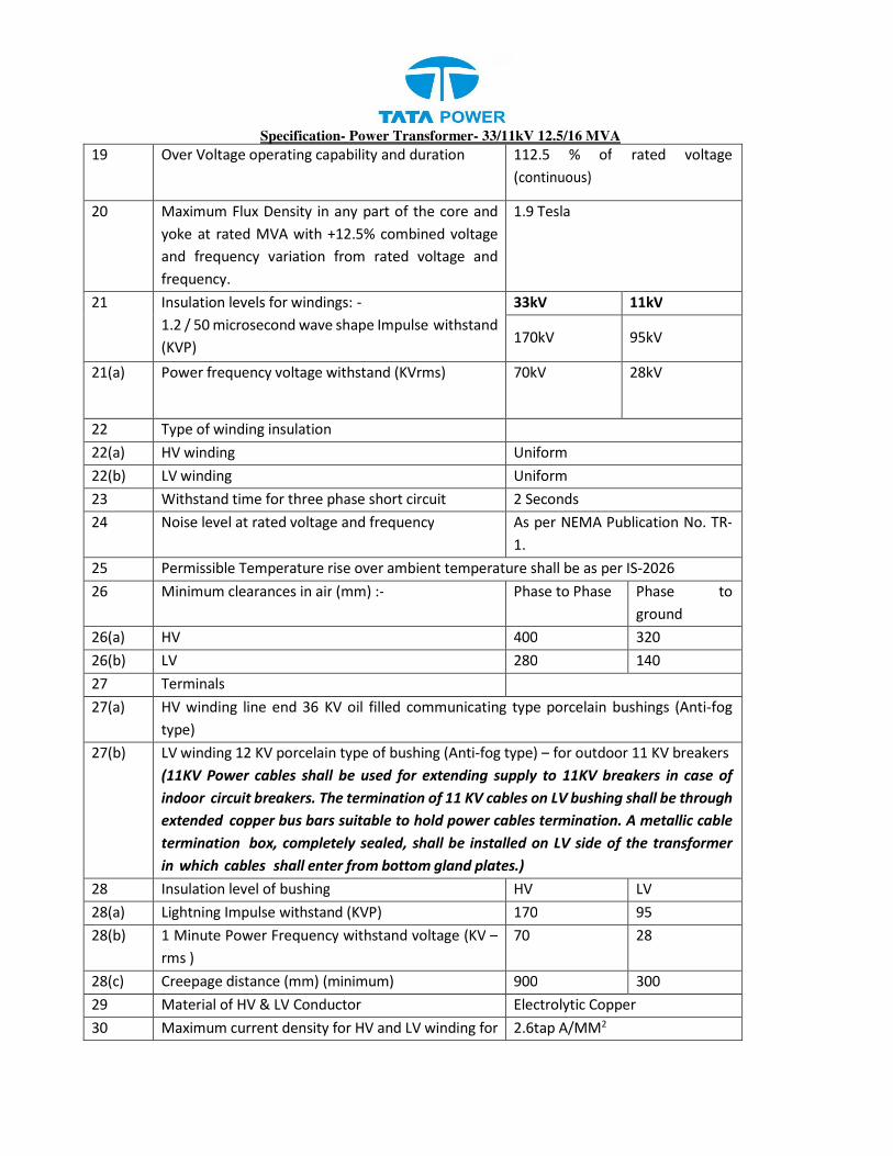
Specification- Power Transformer- 33/11kV 12.5/16 MVA
19 Over Voltage operating capability and duration 112.5 % of rated voltage
(continuous)
20 Maximum Flux Density in any part of the core and
yoke at rated MVA with +12.5% combined voltage
and frequency variation from rated voltage and
frequency.
1.9 Tesla
21 Insulation levels for windings: -
1.2 / 50 microsecond wave shape Impulse withstand
(KVP)
33kV 11kV
170kV 95kV
21(a) Power frequency voltage withstand (KVrms) 70kV 28kV
22 Type of winding insulation
22(a) HV winding Uniform
22(b) LV winding Uniform
23 Withstand time for three phase short circuit 2 Seconds
24 Noise level at rated voltage and frequency As per NEMA Publication No. TR-
1.
25 Permissible Temperature rise over ambient temperature shall be as per IS-2026
26 Minimum clearances in air (mm) :- Phase to Phase Phase to
ground
26(a) HV 400 320
26(b) LV 280 140
27 Terminals
27(a) HV winding line end 36 KV oil filled communicating type porcelain bushings (Anti-fog
type)
27(b) LV winding 12 KV porcelain type of bushing (Anti-fog type) – for outdoor 11 KV breakers
(11KV Power cables shall be used for extending supply to 11KV breakers in case of
indoor circuit breakers. The termination of 11 KV cables on LV bushing shall be through
extended copper bus bars suitable to hold power cables termination. A metallic cable
termination box, completely sealed, shall be installed on LV side of the transformer
in which cables shall enter from bottom gland plates.)
28 Insulation level of bushing HV LV
28(a) Lightning Impulse withstand (KVP) 170 95
28(b) 1 Minute Power Frequency withstand voltage (KV –
rms )
70 28
28(c) Creepage distance (mm) (minimum) 900 300
29 Material of HV & LV Conductor Electrolytic Copper
30 Maximum current density for HV and LV winding for 2.6tap A/MM2

Specification- Power Transformer- 33/11kV 12.5/16 MVA
rated current
31 Polarization index (HV to LV, HV to Earth & LV to
earth)
IR Test = 1 minute value/ 15
seconds value will not be less
than 1.5.
IR Test = 10 minutes value / 1
minute value will not be more
than 5 and less than 1.5.
32 Core Assembly Boltless type
33 Temperature Indicator
33(a) Oil One number
33(b) Winding One number
34 Losses: - The losses shall not exceed the value given below
MVA Rating No-load losses
(Fixed loss) KW
Load losses at
75°C KW
Percentage impedance voltage on
normal tap and MVA base at 75o C
12.5/16 9.7 70 10
2.1 MARSHALLING BOX
A metal enclosed, weather, vermin and dust proof marshalling box fitted with required glands,
locks, glass door, terminal Board, heater with switch, illumination lamp with switch etc. shall be
provided with each transformer to accommodate temperature indicators, terminal blocks etc. It shall
have degree of protection of IP 55 or better as per IS: 2147 (Refer Clause 3.12).
2.2 CAPITALIZATION OF LOSSES AND LIQUIDATED DAMAGES
Capitalization of losses will be as per Annexure B which is attached herewith. No (+)ve tolerance shall
be allowed at any point of time, on the quoted losses after the award. In case, the losses during
type testing, routine testing etc. are found above the quoted losses, the award shall stand cancelled.
In such a case, the CPG money shall also be forfeited.
2.3 PERFORMANCE
i) Transformer shall be capable of withstanding for two seconds without damage to any external
short circuit, with the short circuit MVA available at the terminals.
ii) The maximum flux density in any part of the core and yoke at rated Voltage and frequency
shall be such that the flux density with +12.5% combined voltage and frequency variation from
rated voltage and frequency shall not exceed 1.9Tesla.
iii) Transformer shall under exceptional circumstances due to sudden disconnection of the load, be
capable of operating at the voltage approximately 25% above normal rated voltage for a period
of not exceeding one minute and 40% above normal for a period of 5 seconds.
iv) The transformer may be operated continuously without danger on any particular tapping at

Specification- Power Transformer- 33/11kV 12.5/16 MVA
the rated MVA± 1.25% of the voltage corresponding to the tapping.
v) The thermal ability to withstand short circuit shall be demonstrated by calculation.
vi) Transformer shall be capable of withstanding thermal and mechanical stress caused by any
symmetrical and asymmetrical faults on any winding.
2.4 DRAWINGS/ DOCUMENTS INCORPORATING THE FOLLOWING PARTICULARS SHALL BE
SUBMITTED WITH THE BID
a) General outline drawing showing shipping dimensions and overall dimensions, net weights
and shipping weights, quality of insulating oil, spacing of wheels in either direction of
motion, location of coolers, marshalling box and tap changers etc.
b) Assembly drawings of core, windings etc. and weights of main components / parts.
c) Height of center line on HV and LV connectors of transformers from the rail top level.
d) Dimensions of the largest part to be transported.
e) GA drawings / details of various types of bushing
f) Tap changing and Name Plate diagram
g) Type test certificates of similar transformers.
h) Illustrative & descriptive literature of the Transformer.
i) Maintenance and Operating Instructions.
2.5 MISCELLANEOUS
i) Padlocks along with duplicate keys as asked for various valves, marshalling box etc. shall be
supplied by the contractor, wherever locking arrangement is provided.
ii) Foundation bolts for wheel locking devices of Transformer shall be supplied by the Contractor.
2.6 DELIVERY
The full quantity of the equipment’s shall be delivered as per the delivery schedule appended to this
specification.
2.7 SCHEDULES
All Schedules annexed to the specification shall be duly filled by the bidder separately.
2.8 ALTITUDE FACTOR
Necessary correction factors as given in the Indian Standard for oil temperature rise, insulation
level etc. shall be applied to the Standard Technical Parameters given above.
2.9 NAME PLATE
Transformer rating plate shall contain the information as given in clause 15 of IS-2026 (part-I). The
details on rating plate shall be finalized during the detailed engineering. Further, each
transformer shall have inscription of Employer’s name. The name plate shall also include (i) The
short circuit rating , (ii) Measured no load current and no load losses at rated voltage and rated

Specification- Power Transformer- 33/11kV 12.5/16 MVA
frequency, (iii) measured load losses at 75° C ( normal tap only ), (iv) D.C resistance of each
winding at 75° C.
3. SERVICE CONDITIONS
CLIMATIC CONDITIONS
The service conditions shall be as follows:
1. Maximum altitude above sea level 1,000m
2. Maximum ambient air temperature 50°C
3. Maximum daily average ambient air temperature 35°C
4. Minimum ambient air temperature 0°C
5. Maximum relative humidity 95%
6. Average number of thunderstorm days per annum (isokeraunic level) 70
7. Average number of rainy days per annum 120
8. Average annual rainfall 150cm
9. Earthquakes of an intensity in horizontal direction - equivalent to seismic acceleration of 0.3g
10. Earthquakes of an intensity in vertical direction - equivalent to seismic acceleration of 0.15g
(g being acceleration due to gravity)
13 .Wind velocity: 300 km/hr, 200 km/hr and 160 km/hr
Environmentally, the region where the equipment will be installed includes coastal areas, subject to high relative
humidity, which can give rise to condensation. Onshore winds will frequently be salt laden. On occasions,
the combination of salt and condensation may create pollution conditions for outdoor insulators. Therefore,
outdoor material and equipment shall be designed and protected for use in exposed, heavily polluted, salty,
corrosive, tropical and humid coastal atmosphere.
4. SYSTEM CONDITIONS
The equipment shall be suitable for installation in supply systems of the following characteristics.
Frequency 50 Hz± 5%
Nominal system voltages 33 KV
11 KV
Maximum system voltages 33KV System 36.3 KV
11 KV System 12 KV
Nominal short circuit level
(Basing on apparent power)
33KV System 31.5KA
11 KV System 13.1KA
Insulation levels : 1.2/50 μ sec
impulse withstand voltage
33KV System 170KV (peak)
11 KV System 75 KV (peak)
Power frequency one minute
withstand (wet and dry)
voltage
33KV System 70KV (rms)
11 KV System 28KV (rms)
Neutral earthing arrangements 11 KV System Solidly earthed
5. CODES & STANDARDS

Specification- Power Transformer- 33/11kV 12.5/16 MVA
5.1 The design, material, fabrication, manufacture, inspection, testing before dispatch and performance
of power transformers at site shall comply with all currently applicable statutory regulations
and safety codes in the locality where the equipment will be installed. The equipment shall also
conform to the latest applicable standards and codes of practice. Nothing in this specification
shall be construed to relieve the contractor of this responsibility.
5.2 The equipment and materials covered by this specification shall conform to the latest applicable
provision of the following standards.
IS:5 Colour for ready mixed paints
IS:325 Three Phase Induction Motors
IS:335 New insulating oil for transformers, switch gears
IS:1271 Classification of insulating materials for electrical machinery
and apparatus in relation to their stability in services
IS:2026(Part I to IV) Power Transformer
IS:2071 Method of high voltage testing
IS:2099 High voltage porcelain bushings
IS:2147 Degree of protection
IS:2705 Current Transformers
IS:3202 Code of practice for climate proofing of electrical equipment
IS:3347 Dimensions for porcelain Transformer Bushings
IS:3637 Gas operated relays
IS:3639 Fittings and accessories for power Transformers
IS:5561 Electric Power Connectors
IS:6600/BS:CP‟10:0 Guide for loading of oil immersed Transformers
IS:10028 Code of practice for selection, installation and maintenance
of transformers, Part I. II and III
C.B.I.P. Publication Manual on Transformers
If the standard is not quoted for any item, it shall be presumed that the latest version of Indian Standard
shall be applicable to that item.
The equipment complying other internationally accepted standards, may also be considered if they
ensure performance superior to the Indian Standards.
5.3 DRAWINGS
a) The contractor shall furnish, within fifteen days after issuing of Letter of Award. Six copies each of
t h e following drawings/documents incorporating the transformer rating for approval.
i) Detailed overall general arrangement drawing showing front and side elevations and plan
of the transformer and all accessories including radiators and external features with details
of dimensions, spacing of wheels in either direction of motion, net weights and shipping

Specification- Power Transformer- 33/11kV 12.5/16 MVA
weights, crane lift for un-tanking, size of lugs and eyes, bushing lifting dimensions,
clearances between HV and L.V terminals and ground, quantity of insulating oil etc.
ii) Assembly drawings of core and winging and weights of main components / parts
iii) Foundation plan showing loading on each wheel land jacking points with respect to centre
line of transformer.
iv) GA drawings details of bushing and terminal connectors.
v) Name plate drawing with terminal marking and connection diagrams.
vi) Wheel locking arrangement drawing.
vii) Transportation dimensions drawings.
viii) Magnetization characteristic curves of PS class neutral and phase side current transformers,
if applicable.
ix) Interconnection diagrams.
x) Over fluxing withstand time characteristic of transformer.
xi) GA drawing of marshalling box.
xii) Control scheme/wiring diagram of marshalling box.
xiii) Technical leaflets of major components and fittings.
xiv) As built drawings of schematics, wiring diagram etc.
xv) Setting of oil temperature indicator, winding temperature indicator.
xvi) Completed technical data sheets.
xvii) Details including write-up of tap changing gear.
xviii) HV & LV bushing.
xix) Bushing Assembly.
xx) Bi-metallic connector suitable for connection to 100 mm2 up to 232 mm2 AAAC Conductor.
xxi) GA of LV cable Box.
xxii) Radiator type assembly.
b) All drawings, documents, technical data sheets and test certificates, results calculations shall be
furnished.
5.4 Any approval given to the detailed drawings by the Employer’s shall not relieve the contractor of
the responsibility for correctness of the drawing and in the manufacture of the equipment. The
approval given by the employer shall be general with overall responsibility with contractor.
6. GENERAL CONSTRUCTIONAL FEATURES
6.1 All material used shall be of best quality and of the class most suitable for working under the
conditions specified and shall withstand the variations of temperature and atmospheric conditions
without distortion or deterioration or the setting up of undue stresses which may impair suitability
of the various parts for the work which they have to perform.
6.2 Similar parts particularly removable ones shall be interchangeable.

Specification- Power Transformer- 33/11kV 12.5/16 MVA
6.3 Pipes and pipe fittings, screws, studs, nuts and bolts used for external connections shall be as per
the relevant standards. Steel bolts and nuts exposed to atmosphere shall be galvanized.
6.4 Nuts, bolts and pins used inside the transformers and tap changer compartments shall be
provided with lock washer or locknuts.
6.5 Exposed parts shall not have pockets where water can collect.
6.6 Internal design of transformer shall ensure that air is not trapped in any location.
6.7 Material in contact with oil shall be such as not to contribute to the formation of acid in oil.
Surface in contact with oil shall not be galvanized or cadmium plated
6.8 Labels, indelibly marked, shall be provided for all identifiable accessories like Relays, switches
current transformers etc. All label plates shall be of in corrodible material.
6.9 All internal connections and fastenings shall be capable of operating under overloads and over-
excitation, allowed as per specified stands without injury.
6.10 Transformer and accessories shall be designed to facilitate proper operation, inspection,
maintenance and repairs.
6.11 No patching, plugging, shimming or other such means of overcoming defects, discrepancies or
errors will be accepted.
6.12 Schematic Drawing of the wiring, including external cables shall be put under the prospane sheet on
the inside door of the transformer marshalling box.
6.13 Painting
6.13.1 All paints shall be applied in accordance with the paint manufacturer’s recommendations.
Particular attention shall be paid to the following:
a) Proper storage to avoid exposure as well as extremes of temperature.
b) Surface preparation prior to painting.
c) Mixing and thinning
d) Application of paints and the recommended limit on time intervals between coats.
e) Shelf life for storage.
6.13.2 All paints, when applied in normal full coat, shall be free from runs, sags, wrinkles, patchiness, brush
marks or other defects.

Specification- Power Transformer- 33/11kV 12.5/16 MVA
6.13.3 All primers shall be well marked into the surface, particularly in areas where painting is evident, and
the first priming coat shall be applied as soon as possible after cleaning. The paint shall be applied by
airless spray according to the manufacturer’s recommendations. However, wherever airless spray is
not possible, conventional spray be used with prior approval of Employer.
6.13.4 The supplier shall, prior to painting protect nameplates, lettering gauges, sight glasses, light fittings
and similar such items.
6.13.5 Cleaning and Surface Preparation
1. After all machining, forming and welding has been completed, all steel work surfaces shall be
thoroughly cleaned of rust, scale, welding slag or spatter and other contamination prior to any
painting.
2. Steel surfaces shall be prepared by Sand/Shot blast cleaning or chemical cleaning by seven tank
process including Phosphate to the appropriate quality.
3. The pressure and Volume of the compressed air supply for the blast cleaning shall meet the work
requirements and shall be sufficiently free from all water contamination prior to any painting.
4. Chipping, scraping and steel wire brushing using manual or power driven tools cannot remove
firmly adherent mill-scale and shall only be used where blast cleaning is impractical.
5. Protective Coating As soon as all items have been cleaned and within four hours of the subsequent
drying, they shall be given suitable anticorrosion protection.
6.13.6 Paint Material
Followings are the type of paints that may be suitably used for the items to be painted at shop and supply
of matching paint to site:
i) Heat resistant paint (Hot oil proof) for inside surface.
ii) For external surfaces one coat of Thermo Setting Paint or 2 coats of Zinc chromate
followed by 2 coats of POLYURETHANE. The color of the finishing coats shall be dark
admiral grey conforming to No.632 or IS 5:1961.
6.13.7 Painting Procedure
1. All painting shall be carried out in conformity with both specifications and with the paint
manufacture’s recommendations. All paints in any one particular system. Whether shop or site
applied, shall originate from one paint manufacturer.
2. Particular attention shall be paid to the manufacture’s instructions on storage, mixing, thinning
and pot life. The paint shall only be applied in the manner detailed by the manufacturer e.g.
brush, roller, conventional or airless spray and shall be applied under the manufacturer’s
recommended conditions. Minimum and maximum time intervals between coats shall be closely
followed.
3. All prepared steel surfaces should be primed before visible re-rusting occurs or within 4 hours

Specification- Power Transformer- 33/11kV 12.5/16 MVA
whichever is sooner. Chemical treated steel surfaces shall be primed as soon as the surface is dry
and while the surface is warm.
4. Where the quality of film is impaired by excess film thickness, (wrinkling, mud cracking or general
softness) the supplier shall remove the unsatisfactory paint coatings and apply another. As a
general rule, dry film thickness should not exceed the specified minimum dry film thickness by
more than 25%. In all instances, where two or more coats of the same paints are specifies, such
coatings may or may not be of contrasting colors.
5. Paint applied to items that are not be painted, shall be removed at supplier's expense, leaving
the surface clean, un-stained and undamaged.
6.13.8 Damages to Paints Work
1. Any damage occurring to any part of the painting scheme shall be made good to the same
standard of corrosion protection and appearance as that originally employed.
2. Any damaged paint work shall be made as follows:
a) The damaged area, together with an area extending 25mm around its boundary, shall be cleaned
down to bare metal.
b) A priming coat shall immediately applied, followed by a full paint finish equal to that originally
applied and extending 50mm around the perimeter of the originally damaged.
3. The repainted surface shall present a smooth surface. This shall be obtained by carefully chamfering
the paint edges before & after priming.
6.13.9 Dry Film Thickness
1. To the maximum extent practicable, the coats shall be applied as a continuous film of uniform
thickness and free of pores. Over-spray, skips, runs, sags and drips should be avoided. The different
coats may or may not be same color.
2. Each coat of paint shall allowed to hardened before the next is applied as per manufacture’s
recommendations.
3. Particular attention must be paid to full film thickness at edges.
4. The requirement for the dry film thickness (DFT) of paint and the material to be used shall be as
given below:
Sl. No Paint Type Area to be
painted
No of
Coats
Total Dry film
thickness(Min)
1 Liquid paint
a) Zinc
Chromate(Primer)
b) POLYURETHANE
Paint (Finish
Coat)
c) Hot Oil paint
Outside
Outside
Inside
02
02
01
45 micron
35 micron
35 micron

Specification- Power Transformer- 33/11kV 12.5/16 MVA
7. DETAILED DESCRIPTION
7.1 Tank
7.1.1 The Transformer tank and cover shall be fabricated from high grade low carbon plate steel of
tested quality. The tank shall be of welded construction.
7.1.2 Tank shall be designed to permit lifting by crane or jacks of the complete transformer assembly
filed with oil. Suitable lugs and bossed shall be provided for this purpose.
7.1.3 All breams, flanges, lifting lugs, braces and permanent parts attached to the tank shall be
welded and where practicable, they shall be double welded.
7.1.4 The main tank body of the transformer, excluding tap changing compartments and radiators,
shall be capable of withstanding pressure of 760mm of Hg.
7.1.5 Inspection hole(s) with welded flange(s) and bolted cover(s) shall be provided on the tank cover. The
inspection hole(s) shall be of sufficient size to afford easy access to the lower ends of the bushings,
terminals etc.
7.1.6 Gaskets of nitrile rubber or equivalent shall be used to ensure perfect oil tightness. All gaskets
shall be closed design (without open ends) and shall be of one piece only. Rubber gaskets used for
flange type connections of the various oil compartments, shall be laid in grooves or in groove-
equivalent sections on bolt sides of the gasket, throughout their total length. Care shall be taken to
secure uniformly distributed mechanical strength over the gaskets and retains throughout the total
length. Gaskets of neoprene and / or any kind of impregnated / bonded core or cork only which
can easily be damaged by over-pressing are not acceptable. Use of hemp as gasket material
is also not acceptable.
7.1.7 Suitable guides shall be provided for positioning the various parts during assemble or dismantling.
Adequate space shall be provided between the cores and windings and the bottom of the tank for
collection of any sediment.
7.1.8 The transformer tank and cover shall be fabricated from good commercial grade low carbon steel
suitable for welding and shall be of adequate thickness.
7.1.9 The tank and the cover shall be of welded construction. All seams shall be welded and where
practicable they shall be double welded.
7.1.10 The tank shall have sufficient strength to withstand without permanent distortion (i) filling by vacuum
and (ii) continuous internal gas pressure of 0.35 atmospheric with oil and operating level.
7.1.11 The tank material shall be as per IS: 2026 or equivalent with ultrasonic testing done for elimination
of defects in rolled plates.
7.1.12 The welding shall be as per prior approved WPS (Welding Procedure Specs) by trained and tested
welders.
7.1.13 The welding plan shall be shown in general i.e. Category-wise or for each type of weld in the
mechanical fabrication drawing, which shall be submitted to Purchaser.
7.1.14 All fittings like elbows, bends etc. shall be seamless as per applicable American or Indian Standards.
7.1.15 No resistance welding of fasteners shall be done anywhere on the transformer.
7.1.16 The tank shall have an oil tight bolted flanged joint near the base of the transformer so that the tank

Specification- Power Transformer- 33/11kV 12.5/16 MVA
can be lifted off to provide access to the core and coils.
7.1.17 To ensure oil tightness, recessed neoprene or equivalent gaskets shall be used.
7.1.18 Manholes with welded flange and bolted covers shall be provided on the tank.
7.1.19 The manhole shall be of sufficient size to afford easy access to the lower ends of all the bushings,
OLTC terminals etc. to permit replacement of auxiliaries without removing tank covers.
7.1.20 Inspection covers on elevation (on vertical plane) shall be provided for all HV bushing turrets.
7.1.21 Suitable guides shall be provided for positioning the various parts during assembly or dismantling.
7.1.22 Adequate space shall be provided between the cores and windings and the bottom of the tank for
collection of any sediment.
7.1.23 All joints including bolted as well as flanged, shall have machined matching surfaces/inner edges with
smooth finish, to ensure leak proof joints.
7.1.24 Lifting eyes or lugs shall be provided on all parts of the transformer requiring independent handling
during assembly or dismantling. In addition, the transformer tank shall be provided with lifting lugs
and bosses properly secured to the sides of the tank, for lifting the transformer either by crane or by
jacks.
7.1.25 The design of the tank, the lifting lugs and bosses shall be such that the complete transformer
assembly filled with oil can be lifted with the use of these lugs without any damage or distortions.
7.1.26 The tank shall be provided with two nos. of suitable copper alloy lugs for the purpose of grounding.
7.1.27 The grounding pads should be mirror finished. Two grounding pads, located on opposite sides of the
tank shall be provided with two tapped holes for connecting it with station ground mat. Necessary
hardware like M10 GS bolts and spring washers shall also be provided for connections.
7.1.28 Each tank shall be equipped with the following valves with standard flange connection for external
piping:
a) One drain valve located on the low voltage side of the transformer and placed to completely drain
the tank. At the option of the Purchaser’s a large valve may be furnished with an eccentric reducer.
This valve shall be equipped with a small sampling cock.
b) One filter valve located at the top of the tank on the high-voltage side. The opening of this valve
shall be baffled to prevent aeration of the oil.
c) One filter valve, located slightly above the bottom of the tank.
d) One relief valve to operate at a pressure below the test pressure for the tank.
e) Other two nos. valves shall also be provided, as required for proper functioning of the transformer.
f) A suitable locking arrangement shall be provided for locking these valves in close/open position.
7.1.29 All valves should be provided with clear open/close position indications. Wherever rising spindle type
valves are provided the valves should be clockwise rotating for closing operations.
7.1.30 For the auxiliary lead wiring from individual instrument to marshalling box, the cables shall be
provided in the conduits.
7.1.31 All the transformers shall be provided with a ladder having 'anti-climbing' device.
7.1.32 Transformer tank shall be of welded sheet steel construction and provided with gaskets steel cover
plates.
7.1.33 Base shall be suitably reinforced to prevent any distortion during lifting. Base channels shall be
Specification- Power Transformer- 33/11kV 12.5/16 MVA
provided with skids and pulling eyes to facilitate handling.
7.1.34 All seams shall be electrically double welded for absolute oil tightness.
7.1.35 Equipotential strips to be provided at the gasket joints and at any other suitable locations.
7.1.36 Suitable arrangement shall be made for mounting HV and LV lightning arrestors of the transformer.
7.1.37 Guards shall be provided for drain, bottom sampling and filter valves to prevent oil pilferage.
7.1.38 Minimum Thickness for the transformer shall be as follows:
Tank Side wall (mm) 10
Tank Top Cover (mm) 12
Tank Bottom Plate (mm) 12
Conservator (mm) 06
7.2 Tank Cover
The transformer top shall be provided with a detachable tank cover with bolted flanged gasket joint.
Lifting lugs shall be provided for removing the cover. The surface of the cover shall be suitable sloped
so that it does not retain rain water.
7.3 UNDER CARRIAGE
The transformer tank filled with oil shall be supported on steel structure with detachable plain rollers.
Suitable channels for movement of roller with transformer shall be space accordingly, rollers wheels
shall be provided with suitable rollers bearings, which will resist rust and corrosion and shall be
equipped with fittings for lubrication.
7.4 CORE
7.4.1 Each lamination shall be insulated such that it will not deteriorate due to mechanical pressure and
the action of hot transformer oil.
7.4.2 The core shall be constructed either from high grade, non-aging Cold Rolled Grain Oriented (CRGO)
silicon steel laminations conforming to HIB grade with lamination thickness not more than 0.23mm
to 0.27mm or better( Quoted grade and type shall be used). The maximum flux density in any part of
the cores and yoke at normal voltage and frequency shall not be more than 1.69 Tesla. The Bidder
shall provide saturation curve of the core material, proposed to be used. Laminations of different
grade(s) and different thickness (s) are not allowed to be used in any manner or under any
circumstances.
CRGO steel for core shall be purchased only from the approved vendors, list of which is available at
http://apps.powergridindia.com/ims/ComponentList/Power-former%20upto%20420%20kV-
CM%20List.pdf
7.4.3 The bidder should offer the core for inspection starting from the destination port to enable
Employer for deputing inspecting officers for detail verification as given below and approval by the

Specification- Power Transformer- 33/11kV 12.5/16 MVA
Employer during the manufacturing stage. Bidder‟s call notice for the purpose should be
accompanied with the following documents as applicable as a proof towards use of prime core
material: The core coils, if found suitable, are to be sealed with proper seals which shall be
opened in presence of the inspecting officers during core- cutting at the manufacturer’s or it’s sub-
vendor’s premises as per approved design drawing.
a) Purchase Order No. & Date.
b) Invoice of the supplier
c) Mills test certificate
d) Packing list
e) Bill of lading
f) Bill of entry certificate to customs
Core material shall be directly procured either from the manufacturer or through their
accredited marketing organization of repute, but not through any agent.
Please refer to “Check-list for Inspection of Prime quality CRGO for Transformers” attached at
Annexure-A. It is mandatory to follow the procedure given in this Annexure.
7.4.4 The laminations shall be free of all burrs and sharp projections. Each sheet shall have an
insulting coating resistant to the action of hot oil.
7.4.5 Purchaser shall impose heavy penalty or black list bidders using seconds/ defective CRGO sheets or
load losses found to be more than stipulated limit
7.4.6 The core frame shall be provided with lugs suitable for lifting the complete core and coil assembly
of the transformer.
7.4.7 The insulation structure for the core to bolts and core to clamp plates, shall be such as to withstand
2000 V DC voltage for one minute.
7.4.8 The completed core and coil shall be so assembled that the axis and the plane of the outer surface
of the core assemble shall not deviate from the vertical plane by more than 25mm.
7.4.9 All steel sections used for supporting the core shall be thoroughly shot or sand blasted, after cutting,
drilling and welding.
1. The finally assembled core with all the clamping structures shall be free from deformation
and shall not vibrate during operation.
7.4.10 The core clamping structure shall be designed to minimize eddy current loss.
7.4.11 The framework and clamping arrangements shall be securely earthed.

Specification- Power Transformer- 33/11kV 12.5/16 MVA
7.4.12 The core shall be carefully assembled and rigidly clamped to ensure adequate mechanical
strength.
7.4.13 Oil ducts shall be provided, where necessary, to ensure adequate cooling inside the core. The
welding structure and major insulation shall not obstruct the free flow of oil through such ducts.
7.4.14 The design of magnetic circuit shall be such as to avoid static discharges, development of short
circuit paths within itself or to the earth clamping structure and production of flux component at
right angle to the plane of the lamination, which may cause local heating. The supporting
framework of the cores shall be so designed as to avoid the presence of pockets, which would
prevent complete emptying of the tank through the drain valve or cause trapping of air during
filling.
7.4.15 The construction is to be of boltless core type. The core shall be provided with lugs suitable for
lifting the complete core and coil assembly. The core and coil assemble shall be so fixed in the tank
that shifting will not occur during transport or short circuits. The supporting frame work of the core
shall be so designed as to avoid presence of pockets which would prevent complete emptying of
tank through drain valve or cause trapping of air during oil filling
7.4.16 The temperature gradient between core & surrounding oil shall be maintained less than 20 deg.
Centigrade. The manufacturer shall demonstrate this either through test (procurement to be
mutually agreed) or by calculation.
7.4.17 Suitable buffer locking arrangement to be provided by providing guide channel, stopper and other
suitable insulating material so that core and its associated channel do not move during
transportation.
7.5 INTERNAL EARTHING
7.5.1 All internal metal parts of the transformer, with the exception of individual laminations and their
individual clamping plates shall be earthed.
a) The grounding lead from the core shall be brought out of the tank through a 11 kV class
bushing and grounded externally.
7.5.2 A protective cover shall be provided for the bushing.
7.5.3 The core grounding rod (stem) through the bushing shall be solid rod (stem).
7.5.4 The design of core grounding arrangement shall be such that the grounding links shall not come out
of core during installation as well service conditions.
7.5.5 The supplier shall submit a drawing clearly showing the details of core grounding.
7.5.6 The core / frame grounding’s both connections shall be brought out through a suitable bushing for
provision of external grounding.
7.5.7 The magnetic circuit shall be connected to the clamping structure at one point only and this shall be

Specification- Power Transformer- 33/11kV 12.5/16 MVA
brought out of the top cover of the transformer tank through a suitably rated insulator. A
disconnecting link shall be provided on transformer tank to facilitate disconnections from ground for
IR measurement purpose.
7.5.8 Coil clamping rings of metal at earth potential shall be connected to the adjacent core clamping
structure on the same side as the main earth connections.
7.6 WINDING
7.6.1 Winding shall be subjected to a shrinking and seasoning process, so that no further shrinkage
occurs during service. Adjustable devices shall be provided for taking up possible shrinkage in
service.
7.6.2 All low voltage windings for use in the circular coil concentric winding shall be wound on a
performed insulating cylinder for mechanical protection of the winding in handling and placing
around the core.
7.6.3 Winding shall not contain sharp bends which might damage the insulation or produce high
dielectric stresses. No strip conductor wound on edge shall have width exceeding six times the
thickness.
The conductors shall be of electrolytic grade copper free from scales and burrs. The conductor
insulation shall be made from high-density (at least 0.75 gm/cc) paper having high mechanical
strength. The barrier insulation including spacers shall be made from high- density pre- compressed
pressboard (1.1 gm/cc minimum for load bearing and 1 to 1.3 gm/cc minimum for non-load
bearing) to minimize dimensional changes.
7.6.4 Materials used in the insulation and assembly of the windings shall be insoluble, non catalytic and
chemically inactive in the hot transformer oil and shall not soften or the otherwise affected
under the operating conditions.
7.6.5 Winding and connections shall be braced to withstand shocks during transport or short circuit.
7.6.6 Permanent current carrying joints in the windings and leads shall be welded or brazed. Clamping
bolts for current carrying parts inside oil shall be made of oil resistant material which shall not be
affected by acidity in the oil steel bolts, if used, shall be suitably treated.
1. Terminals of all windings shall be brought out of the tank through bushings for external
connections. The winding shall be brought out through bushing and provided with suitable
terminal connectors, the details of which will be forwarded later.
2. The tolerance for the winding resistance measurement for different phases but at same taps shall
be limited to 1%. The windings shall be brought out through bushing. The windings shall be
designed to withstand the specified thermal and dynamic short-circuit stresses.
3. The end turns of the high voltage windings shall have reinforced insulation to take care of the
voltage surges likely to occur during switching or any other abnormal condition.

Specification- Power Transformer- 33/11kV 12.5/16 MVA
4. Winding shall be suitable for connection of reactors or capacitors which would be subjected to
frequent switching. All the windings shall be capable of withstanding stresses that may be caused
by such switching.
5. Primary and secondary windings shall be constructed from high- conductivity (copper conductors),
Double Paper Covered (DPC) with minimum 30% overlapping of insulation at each layer copper
conductor.
6. The insulation between core and bolts and core and clamps shall withstand 2.5 kV for one minute.
7. Proper bonding of inter layer insulation with the conductor shall be ensured. Test for bonding
strength shall be conducted as per standards.
8. All turns of windings shall be adequately supported (by which material) to prevent movement. The
core/coil assembly shall be securely held in position to avoid any movement under short circuit
conditions.
9. The joints in the winding shall be avoided but if it is necessary then, these shall be properly
brazed and the resistance of the joints shall be less than that of parent conductor. Crimping is
not allowed at any joints.
7.6.7 The completed core and coil assemble shall be dried in vacuum at not more than 0.5mm of mercury
absolute pressure and shall be immediately impregnated with oil after the drying process to ensure
the elimination of air and moisture within the insulation. Vacuum may be applied in either vacuum
over or in the transformer tank.
7.6.8 The winding shall be so designed that all coil assembles of identical voltage ratings shall be
interchangeable and field repairs to the winding can be made readily without special equipment. The
coils shall have high dielectric strength.
7.6.9 Coils shall be made of continuous smooth high grade electrolytic copper conductor, shaped and
braced to provide for expansion and contraction due to temperature changes.
7.6.10 Adequate barriers shall be provided between coils and core and between high and low voltage coil.
End turn shall have additional protection against abnormal line disturbances.
7.6.11 The insulation of winding shall be designed to withstand voltage stress arising from surge in
transmission lines due to atmospheric or transient conditions caused by switching etc.
7.6.12 Tapping shall not be brought out from inside the coil or from intermediate turns and shall be so
arranged as to preserve as far as possible magnetic balance of transformer at all voltage ratios.
7.6.13 Magnitude of impulse surges transferred from HV to LV windings by electromagnetic induction and
capacitance coupling shall be limited to BILL of LV winding.

Specification- Power Transformer- 33/11kV 12.5/16 MVA
7.6.14 The coils shall be supported between adjacent sections by insulating spacers, and the barriers
bracings and other insulation used in the assembly of the windings shall be arranged to ensure a free
circulation of the oil and to reduce hot spots in the windings
7.6.15 Coils should be transposed to minimize magnetic forces and extra supports shall provide for inter-
disc connection.
7.6.16 All materials used in the insulation and assembly of the winding shall be new, insoluble, non-catalytic,
and chemically inactive in the hot transformer oil, and shall not soften or otherwise be adversely
affected under the operating conditions.
7.6.17 The current density of coil shall not exceed 2.6 Amps/ square mm at min tap of respective PTR’s
higher rating.
7.6.18 All threaded connections shall be provided with locking facilities. All leads from the winding to the
terminal board and bushings shall be rigidly supported to prevent injury from vibration. Guide tubes
shall be used where practicable.
7.7 Insulating paper and insulating press board
1. The bidder shall submit characteristics along with make for all the type of insulation papers and
Pressboards to be used with the offer.
2. Inter layer insulation both for HV and LV windings shall be Epoxy diamond dotted Kraft paper and
compressed pressboard of reputed make (subject to approval of Tata Power).
3. For Winding insulation, only Double Paper Covered insulation is acceptable with laying in opposite
direction to each other and each paper must have overlapping more than 60% of its width.
4. Kraft paper and Pressboard should be made of pure Cellulose from soft wood pulp manufactured from
sulphate process. No additive, adhesive or coloring matter shall be present.
5. Kraft paper and Pressboard should be of class A (105°C) insulation material.
6. All spacers, axial wedges / runners used in windings shall be made of pre-compressed solid pressboard.
7. All axial wedges/runners shall be properly milled to dovetail shape so that they pass through the
designed spacers freely.
8. Insulation shearing, milling and punching operations shall be carried out in such a way, that there
should not be any burr, sharp edges and dimensional variations.
9. Kraft paper self-adhesive tape to be used for bonding of insulating paper layer, spanner and
paperboards that are immersed in the oil filled transformer.
Below required values could be verified if required at any stage of the inspection and it should fulfill
the requirement as per below table:
Characteristics Kraft Paper Pressboard (all Sizes)

Specification- Power Transformer- 33/11kV 12.5/16 MVA
1. Dimension As specified by bidder with +5%
tolerance.
As specified by bidder with
tolerance as per IS1576.
2. Apparent Density >0.80 g/cm3 as per IS1576 w.r.t Thickness
3. pH of Aqueous extract 6-8% 6-8%
4. Electrical strength i) in
air
ii) In Oil
7KV/mm
----------
12KV/mm
35KV/mm
5. Ash content Maximum 1% Maximum 0.7
6. Moisture content Maximum 8% Maximum 8%
7. Oil absorption ----------------- Minimum 9%
Bidder has to submit the test certificates as per IS-9335, IS-1576 for all type of insulating materials covering above
stated parameters along with below parameters during stage inspection:
1. Substance (Grammage) (g/m3)
2. Compressibility
3. Tensile strength
4. Conductivity of water extract
5. Shrinkage in air
6. Flexibility
7. Cohesion between plies1.
8. Elongation
9. Air permeability
10. Tear index
11. Heat stability
7.8 INSULATING OIL
7.7.1 The insulating oil for the transformer shall be of EHV grade, generally conforming to IS: 335. No
inhibitors shall be used in the oil.
7.7.2 The quantity of oil required for the first filling of the transformer and its full specification shall be
stated in the bid. transformer shall supplied complete with all fittings, accessories and new
transformer oil required for first filling plus 10% extra oil. The extra quantity of oil shall be
supplied in non-returnable drums along with the oil required for the radiator banks.
7.7.3 The design and materials used in the construction of the transformer shall be such as to reduce
the risk of the development of acidity in the oil.
7.7.4 The oil parameters shall be as per Table-1 of IS 335.
7.9 VALVES
i) Valves shall be of forged carbon steel upto 50mm size and of gun mental or of cast iron bodies
with gun metal fittings for sizes above 50mm. They shall be of full way type with screwed ends and

Specification- Power Transformer- 33/11kV 12.5/16 MVA
shall be opened by turning counter clockwise when facing the hand wheel. There shall be no oil
leakage when the valves are in closed position.
Each valve shall be provided with an indicator to show the open and closed positions and shall be
provided with facility for padlocking in either open or closed position. All screwed valves shall be
furnished with pipe plugs for protection. Padlocks with duplicate keys shall be supplied along
with the valves.
ii) All valves except screwed valves shall be provided with flanges having machined faced drilled to suit
the applicable requirements, Oil tight blanking plates shall be provided for each connection for use
when any radiator is detached and for all valves opening to atmosphere. If any special radiator
valve tools are required the contractor shall supply the same.
iii) Each transformer shall be provided with following valves on the tank:
a) Drain valve so located as to completely drain the tank & to be provided with locking
arrangement.
b) Two filter valves on diagonally opposite corners of 50mm size & to be provided with locking
arrangement.
c) Oil sampling valves not less than 8mm at top and bottom of main tank & to be provided with
locking arrangement.
d) One 15mm air release plug.
e) Valves between radiators and tank. Drain and filter valves shall be suitable for applying vacuum
as specified in the specifications.
7.10 ACCESSORIES
7.10.1 Bushing
i) All porcelain used in bushings shall be homogeneous, non-porous, uniformly glazed to brown
colour and free from blisters, burns and other defects.
ii) Stress due to expansion and contraction in any part of the bushing shall not lead to deterioration.
iii) Bushing shall be designed and tested to comply with the applicable standards.
iv) Bushing rated for 400A and above shall have non-ferrous flanges and hardware.
v) Fittings made of steel or malleable iron shall be galvanized
vi) Bushing shall be so located on the transformers that full flashover strength will be utilized.
Minimum clearances as required for the BIL shall be realized between live parts and live parts to
earthed structures.
vii) All applicable routine and type tests certificates of the bushings shall be furnished for approval.
viii) Bushing shall be supplied with bi-metallic terminal connector/ clamp/ washers suitable for fixing to
bushing terminal and the Employers specified conductors. The connector/clamp shall be rated to
carry the bushing rated current without exceeding a temperature rise of 550 Co ver an ambient
of 500 C. The connector/clamp shall be designed to be corona free at the maximum rated line to
Specification- Power Transformer- 33/11kV 12.5/16 MVA
ground voltage.
ix) Bushing of identical voltage rating shall be interchangeable.
x) The insulation class of high voltage neutral bushing shall be properly coordinated with the
insulation class of the neutral of the low voltage winding.
xi) Each bushing shall be so coordinated with the transformer insulation that all flashover will occur
outside the tank.
xii) The extended bushing bus bars shall be used for termination of 11 KV cables. LV busing shall be
housed in completely sealed metallic enclosure.
xiii) Sheet steel, weather, vermin and dust proof cable box fitted with required glands, locks, glass
door, terminal Board, heater with switch, illumination lamp with switch, water- tight hinged and
padlocked door of a suitable construction shall be provided with each transformer to
accommodate 11 KV cables etc. The box shall have slopping roof and the interior and exterior
painting shall be in accordance with the specification. Padlock along with duplicate keys shall be
supplied for marshaling box. The degree of protection shall be IP-55 or better. To prevent
internal condensation, a metal clad heater with thermostat shall be provided. The heater shall be
controlled by a MCB of suitable rating mounted in the box. The ventilation louvers, suitably padded
with felt, shall also be provided. The louvers shall be provided with suitable felt pads to prevent
ingress of dust. All incoming cables shall enter the kiosk from the bottom and the minimum
4mm thick, non-magnetic, gland plate shall not be less than 600 mm from the base of the box. The
gland plate and associated compartment shall be sealed in suitable manner to prevent the
ingress of moisture from the cable trench – for those transformers which are used in partly indoor
substation, If required as per BOQ, a cable box for LV bushings shall be provided.
7.10.2 Protection & Measuring Devices
i) Oil Conservator Tank
a) The Conservator tank shall have adequate capacity between highest and lowest visible levels
to meet the requirement of expansion of the total cold oil volume in the transformer and cooling
equipment.
b) The conservator tank shall be bolted into position so that it can be remove for cleaning
purposes.
c) The conservator shall be fitted with magnetic oil level gauge with low level electrically insulated
alarm contact.
d) Plain conservator fitted with silica gel breather.
ii) Oil preserving equipment shall be conservator (expansion tank) type. The conservator shall have two
filter valves, one at the bottom at one end, the other at the top, opposite end, in addition to the valve
specified in the Accessories for the main tank. The conservator or expansion tank shall also have a
shutoff valve and a small drain valve and sampling cock, the latter so arranged as not to interfere with
oil lines. The oil level gauges (prismatic and magnetic) shall be mounted on the conservator or
expansion tank. The top of the conservator shall have contact with atmosphere through two silica gel

Specification- Power Transformer- 33/11kV 12.5/16 MVA
breathers to facilitate replacement of breather without having to keep Buchholz relay inoperative.
The silica gel breathers shall have Polyurethane Type body & it should be transparent and UV
protected.
iii) Conservator oil preservation bag (atmoseal bag) shall be provided with a design such that it can be
installed at site with ease without any special tools and tackles. The price for COPS bag shall be clearly
mentioned in the price schedule at the specified place. With COPS type conservator shall supply air
or nitrogen filing arrangement with all accessories needed at the time of commission and pressure
gauge arrangement shall be provided for monitoring COPS bag pressure.
iv) Proper valve arrangement (Two top valve & one bottom valve on conservator) is to be provided for
proper oil filling.
v) Prismatic oil level indicators with red colour float shall be provided on main tank and OLTC tank
Conservator. Dual contacts are required for both MOGs (Main Tank & OLTC conservator).
a) Separate conservator tank shall be provided for OLTC. 120L tank shall be used for 66KV.
vi) Pressure Relief Device.
The pressure relief device provided shall be of sufficient size for rapid release of any pressure that
may be generated in the tank and which may result in damage of the equipment. The device shall
operate at a static pressure of less than the hydraulic test pressure of transformer tank. It shall be
mounted direct on the tank. A pair of electrically insulated contract shall be provided for alarm
and tripping.
vii) Buchholz Relay
A double float type Buchholz relay shall be provided with reed switch. Any gas evolved in the
transformer shall collect in this relay. The relay shall be provided with a test cock suitable for a
flexible pipe connection for checking its operation. A copper tube shall be connected from the gas
collector to a valve located about 1200 mm above ground level to facilitate sampling with the
transformer in service. The device shall be provided with two electrically independent potential free
contracts, one for alarm on gas accumulation and the other for tripping on sudden rise of pressure.
viii) Temperature Indicator
a) Oil Temperature Indicator (OTI)
The transformers shall be provided with a micro switch contact type thermometer with 150 mm
dial for top oil temperature indication. The thermometer shall have adjustable, electrically
independent potential free alarm and trip contacts. Maximum reading pointer and resetting
device shall be mounted in the local control panel. A temperature sensing element suitably
located in a pocket on top oil shall be furnished. This shall be connected to the OTI by means of
capillary tubing. Accuracy class of OTI shall be ± 1% or better. One No electrical contact capable of
operating at 5 A ac at 230 volt supply.

Specification- Power Transformer- 33/11kV 12.5/16 MVA
b) Winding Temperature indicator (WTI)
A device for measuring the hot spot temperature of the winding shall be provided. It shall
comprise the following.
i) Temperature sensing element.
ii) Image Coil.
iii) Micro switch contacts.
iv) Auxiliary CTS, If required to match the image coil, shall be furnished and mounted in the local
control panel.
v) 150mm dial local indicating instrument with maximum reading pointer mounted in local panel
and with adjustable electrically independent ungrounded contacts, besides that required for
control of cooling equipment, one for high winding temperature alarm and on for trip.
vi) Two number electrical contact each capable of operating at 5 A ac at 230 Volt supply.
7.10.3 Oil Preservation Equipment
7.10.3.1 O i l Sealing
The oil preservation shall be diaphragm type oil sealing in conservator to prevent oxidation and
contamination of oil due to contact with atmospheric moisture.
The conservator shall be fitted with a dehydrating filter breather. It shall be so designed that.
i) Passage of air is through a dust filter & Silica gel.
ii) Silica gel is isolate from atmosphere by an oil seal.
iii) Moisture absorption indicated by a change in color of the crystals of the silica gel can be easily
observed from a distance.
iv) Breather is mounted not more than 1400 mm above rail top level.
7.11 MARSHALLING BOX
i) Sheet steel, weather, vermin and dust proof marshaling box fitted with required glands, locks, glass
door, terminal Board, heater with switch, illumination lamp with switch, water- tight hinged
and padlocked door of a suitable construction shall be provided with each transformer to
accommodate temperature indicators, terminal blocks etc. The box shall have slopping roof and the
interior and exterior painting shall be in accordance with the specification. Padlock along with
duplicate keys shall be supplied for marshaling box. The degree of protection shall be IP-55 or better.
ii) The schematic diagram of the circuitry inside the marshaling box be prepared and fixed inside the
door under a propone sheet.
iii) The marshaling box shall accommodate the following equipment:
a) Temperature indicators.
b) Space for accommodating Control & Protection equipment in future for the cooling fan (for

Specification- Power Transformer- 33/11kV 12.5/16 MVA
ONAF type cooling, may be provided in future).
c) Terminal blocks and gland plates for incoming and outgoing cables.
All the above equipment except c) shall be mounted on panels and back of panel wiring shall be used
for inter-connection. The temperature indicators shall be so mounted that the dials are not more
than 1600 mm from the ground level and the door (s) of the compartment(s) shall be provided
with glazed window of adequate size. The transformer shall be erected on a plinth which shall
be 2.5 feet above ground level.
iv) To prevent internal condensation, a metal clad heater with thermostat shall be provided. The
heater shall be controlled by a MCB of suitable rating mounted in the box. The ventilation
louvers, suitably padded with felt, shall also be provided. The louvers shall be provided with
suitable felt pads to prevent ingress of dust.
v) All incoming cables shall enter the kiosk from the bottom and the gland plate shall not be less
than 450 mm from the base of the box. The gland plate and associated compartment shall be
sealed in suitable manner to prevent the ingress of moisture from the cable trench.
7.12 TAPCHANGER
7.12.1 ON-LOAD TAP-CHANGERS
i) The 12.5/16 MVA transformers shall be provided with On-load Taps. Specification of OLTC is
attached herewith as Annexure.
ii) The Transformer with off-load tap changing gear shall have taps ranging from +5% to -15% in 9
equal steps of 2.5% each for Off Load Tap.
iii) The tap changing switch shall be located in a convenient position so that it can be operated from
ground level. The switch handle shall be provided with locking arrangement along with tap
position indication, thus enabling the switch to be locked in position
iv) The tapping range of On Load Tap Changer shall be +5% to -15% in steps of 1.25% each. The
no of taps shall be 17.The On Load Tap Changer shall be supplied with RTCC panel and AVR
(Automatic Voltage Regulating Relay)
v) The Continuous current rating of the tap changer shall be based on connected winding rating and
shall have liberal and ample margin. Lower rated tap changers connected in parallel are not
acceptable.
vi) The on-load tap changing equipment shall have the provision for mechanical and electrical
control from a local position and electrical control from a remote position. For local mechanical
operation, the operating handle shall be brought outside the tank for operation from floor level
with provision to lock the handle in each tap position. Remote electrical operation shall have
an AUTO-MANUAL selection at the remote location. When selected AUTO, the tap changing gear

Specification- Power Transformer- 33/11kV 12.5/16 MVA
shall maintain steady voltage within practical limit on the transformers secondary bus from which
the reference shall not respond to transient variation of voltage due to grid disturbance and
system fault.
vii) The required voltage relay shall not be sensitive to frequency variation and shall be suitable
for sensing voltage from the secondary of potential transformers mounted on the 33KV, or 11KV
bus.
viii) The tap changer shall be provided with over-current protection in order to prevent the tap-
change operation during a short circuit, which would to greatly stress the contacts of the diverter
switch. The function of protection shall be arranged as follows;
(i) Whenever over current occurs, the control circuit for commanding OLTC motor operation shall
be blocked by the normally close contracts of the over current relays.
(ii) If during tap change over current occurs, the OLTC motor circuit shall be blocked through the
mechanical cam switch, which is close from the very beginning to the very end of every
tap change operation and to the normally open contacts of the over current relays. The stop
action of the motor shall be made through the motor brake contactor.
ix) The design of the tap changing equipment shall be such that the mechanism will not stop in any
intermediate position; however, if the mechanism through faulty operation does stop in an
intermediate position, the full load must be carried by the transformer without injury to the
equipment. The mechanical position indicator shall be equipped in the motor drive cubicle. The
motor shall be designed to be of step control. In any case the operation shall be of step by step.
x) The voltage regulating relay shall be supplied together with the timer and under voltage relay. The
signal order from the voltage regulating relay to execute the tap changer operation, when the
regulating voltage is out of the voltage regulating level shall be designed to be delayed by the
adjustable timer. If the control voltage abnormally falls, the movement of the tap changer shall be
locked by the contact of the under voltage relay, even if the contacts of the voltage regulating relay
are working.
xi) The control circuit of the transformer shall be completely designed and provisions shall be made for
parallel operation with another transformer.
xii) The following accessories, control and selector switches and other necessary accessories shall be
furnished.
Remote tap changer control board
(Placed in the control room)
• Voltmeter
• “AUTO-MANUAL” control switch
• “RAISE-LOWER” control switch
• Tap position indicator
• Tap changer operation program indicator.
Transformer Tap Changer driving mechanism control cubicle

Specification- Power Transformer- 33/11kV 12.5/16 MVA
• “REMOTE-LOCAL-TEST” selector switch
• “AUTOMATIC-MANUAL” control switch
• “RAISE-LOWER” control switch
• Tap position indicator
• Tap changer operation program indicator
• Voltmeter
• Tap change operation counter
• Means for manual operation when power supply is lost
1. OLTC shall have the entire feature to meet the requirement. The equipment shall conform to the latest
applicable Indian standard / IEC standard. Equipment complying with any other authoritative standards such
as British, VDE etc. shall also be considered if offered.
2. The OLTC gear shall be designed to complete successfully tap changes for the maximum current to which
transformer can be loaded i.e. 120% of the rated current. Devices shall be incorporated to prevent tap change
when the through current is in excess of the safe current that the tap changer can handle. The OLTC gear shall
withstand through fault currents without injury.
3. When a tap change has been commenced it shall be completed independently of the operation of the control
relays and switches. Necessary safeguards shall be provided to allow for failure of auxiliary power supply or any
other contingency which may result in the tap changer movement not being completed once it is commenced.
4. OLTC shall be a separate compartment & should be external to transformer tank. Oil in compartments which
contain the making and breaking contacts of the OLTC shall not mix with oil in other compartments of the OLTC
or with transformer oil. Gases released from these compartments shall be conveyed by a pipe to a separate oil
conservator or to a segregated compartment within the main transformer conservator. A OSR with shut off
valves and MOG shall be installed between OLTC and conservator tank. The OLTC conservator shall be provided
with prismatic oil level gauges with red color float. The length and alignment of the MOG and OSR pipe shall be
such that, the transformer does not trip by the vibration of the pipe.
5. Oil in compartments of OLTC which do not contain the make and break contacts, shall be maintained under
conservator head through valve pipe connections. Any gas leaving these compartments shall pass through the
OSR relay before entering the conservator. The cable entry of OSR should be from bottom end instead from
side
6. Oil filled compartments shall be provided with filling plug, drain valve with plug, air release vent, oil sampling
device, inspection opening with gasket and bolted cover with lifting handles.
7. The OLTC motor shall be provided with 415 V auto changeover facilities. For the control of OLTC, Tap change
control relay (a-eberle make) shall be provided by purchaser. Tap position indication along with the various
alarms of tap changer shall be indicated in the marshaling box.
8. Separate OLTC tank should be provided at a height lower than that of the main conservator tank so that the
same is easily accessible for maintenance.
9. OLTC driving mechanism and its associated control equipment shall be mounted in an outdoor, weather proof
cabinet, which shall include:

Specification- Power Transformer- 33/11kV 12.5/16 MVA
• Driving motor (415 V - 3 phase, 50 Hz, AC squirrel cage)
• Motor starting contactor with thermal overload relays, isolating switch and HRC fuses.
• Duplicate sources of power supply with automatic changeover from the running source to the standby source
and vice versa.
• End Limit Switch shall be provided to prevent operation beyond extreme taps & Contacts shall be provided
for operation through SCADA.
• Limit switch to cut off electrical operation on insertion of manual handle (Contacts shall be provided for
operation through SCADA).
• Local/Remote selector switches shall be provided with status indication.
• Control switch: Raise/off/lower (spring return to normal type). (Contacts shall be provided for operation
through SCADA).
• Remote/local selector switch (maintained contact type). (Contacts shall be provided for operation through
SCADA).
• Mechanical tap position indicator showing rated tap voltage against each position and resettable maximum
and minimum indicators.
• Limit switches to prevent motor over travel in either direction & final mechanical stops.
• Brake or clutches to permit only one tap change at a time on manual operation.
• Emergency manual operating device (hand crank or hand wheel).
• Electrically interlocked reversing contactors (preferably also mechanically interlocked).
• 240V, 50 HZ, AC space heaters with switch and MCB.
• Interior lighting fixture with lamp door switch and MCB.
• Gasketted and hinged door with locking arrangement.
• Terminal blocks, internal wiring, earthing terminals and cable glands for power and control cables.
• Necessary relays, contactors, current transformers etc.
• Thermal device or other means shall be provided to protect the motor and control circuit. All relays, switches,
fuses etc. shall be mounted in local OLTC control cabinet and shall be clearly marked for the propose of
identification.
• A five digit counter shall be fitted to the tap changing equipment to indicate the number of operation
completed.
• The equipment shall be suitable for supervisory control and indication with make before break multi-way
switch, having one potential free contact for each tap position. This switch shall be provided in addition to any
other switch/switches which may be required for remote tap position indication.’
• Operation from the local or remote control switch shall cause one tap movement only until the control switch
is returned to the off position between successive operations.
• OLTC shall be provided with PRV.
• Suitable manholes covers should be provided on the sidewalls to give access to the selector switches of the
OLTC. There should be ample access for opening /Reconnecting tap-leads to the OLTC from all sides.
• Suitable valves shall be provided to take sample of oil from the OLTC chamber during operation of the
transformer.
10. Control Requirements for OLTC-

Specification- Power Transformer- 33/11kV 12.5/16 MVA
The following electrical control features shall be provided:
• Positive completion of load current transfer, once a tap change has been initiated, without stopping on any
intermediate position, even in case of failure of external power supply.
• Only one tap change from each tap change impulse even if the control switches or push button is maintained
in the operated position.
• Cut-off of electrical control when manual control is resorted to. It shall not be possible to operate the electric
drive when the manual operating gear is in the use.
• Cut-off of a counter impulse for a reverse tap change until the mechanism comes to rest and resets the circuits
for a fresh operation.
• Cut-off of electrical control when it tends to operate the tap beyond its extreme position. Mechanical limit
switches shall be provided for this purpose to achieve suitable interlocking.
11. Automatic / Parallel Operation with OLTC
OLTC shall be able to do automatic / parallel operations through Transformer Monitoring Unit (TMU).
12. Alarms-
The following alarms shall be provided with the additional contact arrangement for connection to SCADA.
• End Limit Switch
• Manual Operation Insertion
• A.C. supply failure
• Drive motor auto tripped
• Tap Stuck up change delayed
• OSR trip
• MOG Alarms
• PRV Trip
• TC in Progress.
• Any other protective feature, if considered essential by the Bidder.
13. Tap Changer Control and Transformer Monitoring Unit (TMU.) This equipment is not required to be supplied by
the bidder of the Transformer.
14. Auxiliary Power Supply of OLTC, Cooler Control and Power Circuit :
i. Two auxiliary power supplies, 415 volt, three phase four wire shall be provided by the Purchaser for OLTC and
power circuit.
ii. All loads shall be fed by one of the two feeders through an electrically interlocked automatic transfer switch
housed in the marshalling box for on load tap changer control and cooler circuits.
iii. Design features of the transfer switch shall include the following:
a) Provision for the selection of one of the feeder as normal source and other as standby.
b) Upon failure of the normal source, the load shall be automatically transferred after an adjustable time delay
to standby sources.

Specification- Power Transformer- 33/11kV 12.5/16 MVA
c) Indication to be provided at marshalling box for failure of normal source and for transfer to standby source
and also for failure to transfer.
d) Automatic re-transfer to normal source without any intentional time delay following re-energization of the
normal source.
e) Both the transfer and the re-transfers shall be dead transfers and AC feeders shall not be paralleled at any
time.
15. Manual Control
The cranking device for manual operation of the OLTC gear shall be removable and suitable for operation by a
man standing at ground level.
The mechanism shall be complete with the following :
a) Mechanical tap position indicator which shall be clearly visible from near the transformer.
b) A mechanical operation counter.
c) Mechanical stops to prevent over-cranking of the mechanism beyond the extreme tap positions.
d) The manual control considered as back up to the motor operated load tap changer control shall be
interlocked with the motor to block motor start-up during manual operation. The manual operating mechanism
shall be able to show the direction of operation for raising the HV terminal voltage and vice-versa.
1. Bushings provided by the bidder shall be as per IS2099-1986. The bushings shall have high factors of safety
against leakage to ground and shall be so located as to provide adequate electrical clearance between bushings
and grounded parts. Bushings of identical voltage rating shall be interchangeable. All bushings shall be equipped
with suitable terminals of approved type and size and all external current carrying contact surfaces shall be
plated, adequately. The insulation class of the high voltage neutral bushing shall be properly co-ordinate with
the insulation class of the neutral of the high voltage winding.
2. All main winding leads shall be brought out through outdoor type bushings as specified which shall be so located
that the full flashover strength will be utilized and the adequate phase clearance shall be realized.
3. Each bushing shall be so coordinated with the transformer insulation that all flash-over will occur outside the
tank.
4. All porcelain used in bushings shall be of the wet process, homogeneous and free from cavities or other flaws.
The insulation (porcelain) shall be without any joint up to 145kV class. The glazing shall be uniform in colour
and free from blisters, burns and other defects. Stresses due to expansion and contraction in any part of the
bushing shall not lead to deterioration.
5. All oil filled bushing shall be provided with prismatic type oil gauge with red colored float inside the gauge for
oil level indication. The oil gauge glass shall be so designed that it shall give satisfactory service (without
melting/cracking or bulging) at specified site conditions, throughout the life of transformer/bushing. It shall
not turn opaque during the service.
6. In case of oil communicating type bushing (for 33 KV & 11 KV), venting screw of the hollow stud, shall be
provided with Teflon gaskets, to avoid oil leakage problem through the same. Angle of inclination to vertical for
any bushing shall not exceed 30 deg. All bushings shall have puncture strength greater than the dry flash-over
value.
Specification- Power Transformer- 33/11kV 12.5/16 MVA
7. Main terminals shall be solder less terminals, and shall be of the type and size specified in the drawings. The
spacing between the bushings must be adequate to prevent flashover between phases under all conditions of
operation.
8. The Bidder shall give the guaranteed withstand voltages for the above and also furnish a calibration curve with
different settings of the co-ordination gap, to the purchaser to decide the actual gap setting. Bidder’s
recommendations are also invited in this respect.
9. The following routine tests shall be carried out on all bushings in the presence of purchaser’s representative, in
addition to any other specified in the IS:
a) Visual examination
b) One minute dry withstand test
c) Oil tightness test
10. The bushings shall have a link type isolating facility for tap for maintenance tests viz. power factor measurement
etc. (Terminal shall be provided for the measurement of power factor and tan delta).
7.13.2 Gaskets
1. All bolted connection to the tank shall be fitted with suitable oil-tight gaskets which shall give
satisfactory service under the operating conditions. Gaskets shall be of rubber/Nitrate.
2. Special attention shall be given to the methods of making the oil-tight joints between the tank and the
cover as also between the cover and the bushings and all other outlets to ensure that the joints can
be remade satisfactorily and with ease, with the help of semi-skilled labor.
3. Where compressible gaskets are used, steps shall be provided to prevent over compression.
4. All the bolts provided shall be of hot dip galvanized.
5. All bolts shall be provided with one spring washer and two numbers of flat washers and with locking
bolts.
All gasket joints shall be provided with equalizing links to extend earth connections.
7.13.3 Radiators
1. The radiators of cooler units shall be epoxy painted the entire surface including edges should be
cleaned properly before painting to avoid peeling of paint at the edges.
2. Radiators shall be metal spray painted.
3. Bidder shall submit procedure for surface preparation and painting/galvanising of radiators along with
the bid.
4. Price for galvanized radiators shall be quoted separately.
5. The colour shade for the radiator shall be shade 631 as per IS: 5.
6. Tank mounted radiators/coolers shall be of the detachable type with bolted and gasketted flanged
connections.
7. The following accessories shall be provided for radiator:
a) Shut off valves and blanking plates on transformer tank at each point of connection.
b) Top and bottom shut off valves and blanking plates on each radiator.
c) Lifting lugs

Specification- Power Transformer- 33/11kV 12.5/16 MVA
d) Top oil filling plug.
e) Air release plug at top.
f) Oil drain plug at bottom.
g) Top oil filling pump.
8. All radiators shall be tested for:
a) Vacuum test for one hour
b) Hydraulic pressure test using transformer oil for one and half hour (as per ASME)
c) Air test can be done in place of hydraulic pressure test provided.
d) Water tank will be made available for submerging the radiators into water for leak detection.
e) All the tests shall be done in black condition (i.e. before applying any paint).
9. The transformer design shall be such that the radiators and conservator can be mounted on either side
of the tank.
7.13.4 Cooling equipment and its control
1. The transformer shall be provided with ONAF cooling system, which shall be designed to give 80%
output at ONAN and 100% at ONAF. The cooling system shall comprise of two Nos. (2) 50% capacity
radiator banks, to the sides of the tank.
2. The radiators shall have one (1) spare fan for each bank with the automatic switching scheme. In case
of separately mounted radiator banks, it shall be possible to completely isolate each bank for
maintenance and both the banks shall be interchangeable with each other. Bidder shall provide
adequate number of fans of rating 0.25 kW each for cooling of the radiator.
3. Cooling fans shall not be directly mounted on radiator bank which may cause undue vibration. These
shall be located vertically at the sides radiators but on separate support structure so as to prevent
ingress of rain water. Each fan shall be suitably protected by galvanised wire guard to prevent
accidental contact with the blades, the mesh being not greater than 25mm.The exhaust air flow from
cooling fan shall not be directed towards the main tank in any case.
4. Cooling fan must be provided with metal net cover arrangement so that direct contract of birds and
rodents can be avoided with fan blades.
5. An oil flow indicator shall be provided for the confirmation of the oil pump operating in a normal state.
An indication shall be provided in the flow indicator to indicate reverse flow of oil/loss of oil flow.
6. Radiator’s fans motors shall be suitable for operation from 415 volts, three phase 50 Hz power supply
and shall conform to IS:325. Each cooling fan shall be provided with starter thermal overload and short
circuit protection. The motor winding insulation shall be conventional class 'B' type. Motors shall have
hose proof enclosure equivalent to IP55 as per IS:4691.
7. Expansion joint shall be provided, one each on top and bottom cooler pipe connections. Air release
device and oil plug shall be provided on oil pipe connections. Drain valves shall be provided in order
that each section of pipe work can be drained independently.
8. Terminal covers and greasing cups of fan motors shall be accessible without removing the guard. The
air blower shall be removable without dismantling supporting framework. The cooler and its
accessories should be hot dip galvanised or corrosion resistant paint should be applied to it.

Specification- Power Transformer- 33/11kV 12.5/16 MVA
9. Radiators shall be designed to withstand the vacuum and pressure conditions specified for the tank.
Coolers shall be so designed as to accessible for cleaning and painting, to prevent accumulation of
water on the outer surface, to completely drain oil into the tank and to ensure against formation of
gas pockets when the tank is being filled.
10. Radiators shall be connected to the tank by machined steel flanges welded to the cooler units and to
the tank and provided with gaskets. Each cooler unit connection shall be provided on the tank and an
indication for shut off valve which can be fastened in either open or closed position shall be provided.
A separate oil tight blank flange shall be provided for each connection for use when the cooler unit is
detached. Each cooler unit shall have a lifting eye.
11. Automatic operation control of fans shall be provided (with temperature change) from contacts of
winding temperature indicator. The Bidder shall recommend the setting of WTI for automatic
changeover of cooler control from ONAN to ONAF. The setting shall be such that hunting i.e. frequent
start-up operations for small temperature differential do not occur.
12. Suitable manual control facility for cooler fans shall be provided. The changeover to standby fans in
case of failure of service fans shall be automatic. Selector switches and push buttons, shall also be
provided in the cooler control cabinet to disconnect the automatic control and start/stop the fans and
manually.
13. Cooling Fans shall be suitable for operation with a 415 volts, 3 phase, 4 wire, 50 Hz supply. Auto
changeover facility shall be provided to an alternate power supply. The auto changeover scheme shall
be designed based on under-voltage relay logic, to take care voltage dips on 415V supply. Similarly 2
separate control transformers 415/220V with auto changeover facility shall be provided 220V control
circuits for light and heaters in marshalling box.
14. Control equipment for fan motors shall be mounted in a marshalling cabinet adjacent to the
transformer and shall include the necessary connections with automatic control and annunciator
equipment and provision for manual control.
15. The main and starter control circuit and each feeder shall be provided with fuses at both ends so that
in case of fault on any contactor coil only that particular fan will be cut out and other fans can remain
in service. Each feeder shall also be provided with double pole switches to enable isolation of the
corresponding contactor in case the replacement of same is necessitated.
16. Anodized aluminum plate showing details of all terminals nos.& drawing shall be provided along with
marshalling box.
17. Wiring from the current transformers and other control and alarm equipment shall be carried out in
conduits or alternatively in concealed trays and terminated in marshalling box.
18. All terminal blocks for WTI, OTI etc shall be of disconnecting type. Terminal blocks for short circuiting
the current transformer shall be provided separate from the terminal blocks accommodating the
control and indicating circuits. The direct and alternating current terminals shall be isolated from each
other.
19. All tapings of all CTs shall be brought to terminals in the marshalling box. The terminals for the current
transformer leads shall be suitable for accommodating , 6 sq.mm cable leads, with disconnecting type
links, while the terminals for the control and other circuits shall be suitable for accommodating 4

Specification- Power Transformer- 33/11kV 12.5/16 MVA
sq.mm. cable leads. All wires shall be stranded copper, 1.1kV grade insulation, fire resistant and shall
be of reputed make. A minimum of ten spare terminals for control wiring shall be provided.
20. Suitably rated switches shall be provided to enable the control supply to the transformer to be cut off
from the cabinet.
21. Enough Space shall be provided at the bottom of the operating cabinet to mount the Purchaser's
control cables double compression type glands. The number and size of the cable glands shall be
intimated later. All terminal blocks for control shall be rated for 10 Amps.
22. Wire and cable bunching rods shall be provided on all terminal blocks on either side. The wire terminals
shall be engraved or otherwise indelibly marked ferrules and the wires shall be colour coded.
23. All terminal blocks shall have terminal nos. on either side of terminals.
24. Stud type fuse mounts shall be provided with an insulating cover as protection against accidental
contact with live terminals.
25. Drawing pouch with cooler control scheme drawings and TB Schedule covered in the polythene paper
shall be provided inside marshalling box on the door.
26. Acrylic name plates shall be provided on doors of marshalling box cabinet, CT junction box and thermo
junction box. Name plates shall also be provided for all the components inside the marshalling box and
to each cooler component (i.e. Fan No.1, Pump No.1 etc.).
27. Additional 230V, 15 Amps, 3 pin plug point shall be provided for testing purposes inside the marshalling
box.
28. A suitably rated light point with its associated control switches shall be provided inside the housing for
use in emergency.
29. All alarm and control devices shall be ungrounded.
30. Bidder shall furnish a list of the relays, control switches, timers, and other accessories like Bidder,
bushing, MOG etc. indicating the make, type, auxiliary supply requirements, contact rating etc. along
with quotation.
31. The make of devices shall be subject to approval by purchaser, after finalization of order. The bidder
shall furnish O & M manual for all the auxiliary equipment’s.
32. A single metal-enclosed main isolating switch, with HRC fuses, shall be provided for the cooling plant.
33. The contactors, starters and relays provided in the marshalling box shall be reputed make such as
Siemens, L&T, ABB or equivalent make as per purchaser’s approval.
34. The switching in or out of the cooling equipment shall be controlled by winding/oil temperature and
there shall be provided for automatic switching in or out at predetermined temperature levels which
should be capable of adjustment in settings.
35. The local mechanical indication scheme for all annunciation shall be provided in the marshalling box
with mechanical target relays/contactors.
36. The following alarm indication shall be provided each with 2NO contacts.
i. Fan failure
ii. Failure of power supply/control supply.
iii. Conservator oil level low (MOG)/ Oil Level High
iv. PRD Trip./PRV TRIP

Specification- Power Transformer- 33/11kV 12.5/16 MVA
v. Buchholz relay trip/alarm.
vi. Winding Temperature high.
vii. Winding Temperature high-high.
viii. Oil Temperature high.
ix. Oil Temperature high-high.
x. Bucholz/OSR of OLTC trip
xi. OLTC oil level low / OLTC oil level high
SPR Trip
7.13.5 Indicating devices
Following lamp indications shall be provided in Marshalling Box:
a) Control Supply failure.
b) Cooling fan failure for each bank.
c) Common thermal overload trip.
d) One potential free initiating contact for all the above conditions shall be wired independently to
the terminal blocks of marshalling box cabinet
7.13.6 Valves
1. All valves upto and including 100 mm shall be of gun metal or of cast steel. Larger valves may be of
gun metal or may have cast iron bodies with gun metal fittings. They shall be of full way type with
internal screw and shall open when turned counter clock wise when facing the hand wheel.
2. Suitable means shall be provided for locking the valves in the open and close positions. Provision is not
required for locking individual radiator valves.
3. Each valve shall be provided with the indicator to show clearly the position of the valve.
4. All valves flanges shall have machined faces.
5. All valves in oil line shall be suitable be suitable for continuous operation with transformer oil at 100°C.
6. The oil sampling point for main tank shall have two identical valves to be put in series .Oil sampling
valve shall have provision to fix rubber hose of 10 mm size to facilitate oil sampling.
7. A valve or other suitable means shall be provided to fix the on line dissolved gas monitoring system to
facilitate continuous dissolved gas analysis. The location & size of the same shall be finalised during
detail engineering stage.
8. After testing, inside surface of all cast iron valves coming in contact with oil shall be applied with one
coat of oil resisting paint/varnish with two coats of red oxide zinc chromate primer followed by two
coats of fully glossy finishing paint conforming to IS:2932 and of a shade (preferably red or yellow)
distinct and different from that of main tank surface.
9. Outside surface except gasket setting surface of butterfly valves shall be painted with two coats of red
oxide zinc chromate conforming to IS:2074 followed by two coats of fully glossy finishing paint.
All hardware used shall be cadmium plated/electro galvanized
7.13.7 Insulation

Specification- Power Transformer- 33/11kV 12.5/16 MVA
1. The dielectric strength of the winding insulation and of the bushings shall conform to the values given
in IS 2026 (latest version).
2. For rated system voltage 36 the following impulse test voltage shall be offered. System voltage : 12
KV, 36KV, Impulse Test Voltage: 75 kV, 170KV,
3. The transformer shall be capable of operating continuously at its normal rating without exceeding
temperature limits as specified below:
Type of cooling Temperature rise
Winding Natural-oil Forced-air cooled (ONAF) 55 deg.C
Oil All types 45 deg.C
7.13 FITTINGS AND ACCESSORIES
The following fittings and accessories shall be provided on the transformers:
i) Conservator with isolating valves, oil filling hole with cap and drain valve. The conservator vessel
shall be filled with constant oil pressure diaphragm oil sealing system.
1. Magnetic type oil level gauge (150 mm dia) with low oil level alarm contacts. One magnetic-type
oil-level gauge each in Main Tank and OLTC Tank with low and high level alarm contacts for main tank
MOG and low level alarm for OLTC tank MOG and a dial showing minimum, maximum and normal oil
levels. The gauge shall be readable from the transformer base level. It should have cable disconnecting
facility at top of MOG, to facilitate testing of MOG. Along with MOG, prismatic type oil level indicator
(glass window) shall also be provided on conservator.
MOG technical parameters should be according to the below mentioned specifications.
General Technical Requirements for MOG:
S No DESCRIPTION UNITS
1 Mounting Pad
Diameter Mm 150
2 Electric Switch Two no’s Micro Switches
3 Contact Rating 5 Amps 240V AC, 0.25 Amp 24V DC.
4 Switch Operation
Normally open, closes when oil level drops to near
empty condition.
Switch recovers automatically on rising of oil level
5 Mounting of
indicator Vertical
6 Dial Marking Maximum, Minimum, 1/4, 1/2 & 3/4
7 Movement of float
arm In the plane perpendicular to seating face
8 Conservator Dia mm 900 mm

Specification- Power Transformer- 33/11kV 12.5/16 MVA
9 Air cell in
conservator Yes
10 Switches for Low Oil level Alarm, High oil level Alarm.
11 Color Black marking with white/yellow background.
12
Readable from
transformer base
level
Yes
13
Cable disconnecting
facility at top of MOG
to facilitate testing of
MOG
Yes
14 Mechanical
Protection degree IP55
15 Suitable for
transformer rating MVA
16 Packing
Supplier shall ensure that the equipment covered
by this specification shall be prepared for rail/road
transport (local equipment) and be packed in such
a manner so as to protect the equipment from
damage in transit.
17 Marking
The unit shall be appropriately marked as "PROP
ERTY OF TPCODL, BHUBANESWAR" and with
the name of the vendor, Manufacturer
type/serial no. , and year of manufacturing
at suitable location.
18 Warranty
2 years from the date of purchase. In case any
defects are found, the vendor shall replace the
product free of cost.
19 Test Reports
Test certificates to be provided :
1) Specified levels.
2) Switch operation
3) HV Test
4) Leakage Test
5) Insulation Test
20 Acceptance test
Following tests shall be carried out:
1) Specified levels
2) Switch operation
3) HV Test
4) Leakage Test
5) Insulation Test
2. One oil filling valve (inlet)
3. One oil drain valve
4. One filter valve located at the top of the tank on the HV side.

Specification- Power Transformer- 33/11kV 12.5/16 MVA
5. Oil sampling valves.
ii) Prismatic/ toughened glass oil level gauge.
iii) Silica gel breather with oil seal and connecting pipe complete with first fill of activated silica gel or
Alumina mounted at a level of 1300 mm above ground level.
iv) One double float gas detector relay (Buchholz relay) with alarm and tripping contacts to detect
accumulation of gas and sudden changes of oil pressure complete with shut off valves between Relay
and Conservator Tank flange-couplings to permit easy removal without lowering oil level in the main
tank, a bleed valve for gas venting and test valve. The installation shall be weather proof to avoid any
water seepage inside the relay. The cable entry should be from bottom end of Buchholz relay instead
from side.
v) Buchholz relays: should be according to the following general technical parameters as mentioned in below
table.
S. No. Description Unit Requirements
1 Type of relay
Magnetic reed switch type
Buchholz relays suitable for nominal pipe bore of
80 mm with
2 sets of potential free contacts suitable for 24V
to 48V DC.
2 No. of Switching systems 2
3 Suitable for Transformer Rating MVA above 10
4 Nominal Pipe Bore mm 80
5 Type of Flange Round
6 Diameter of flange mm 185
7 Diameter of bolt circle mm 145
8 Number of the bolts 4
9 Size of the bolts M16
10 Flange Thickness mm 16
11 Surge Test (TRIP ) cm/s 90 to 160
12 Gas Volume (ALARM) cc 200 to 300
13 Velocity Test cm/s 90 to 160
14 Relay operating range: Oil
Temperature 10°C to 100°C

Specification- Power Transformer- 33/11kV 12.5/16 MVA
15 Relay operating range: Oil Viscosity
65 to 75 centistokes at 10°C, 2 to
3.5 centistokes at 100°C
16 Element Test With oil, at 1.75Kg/cm2 for 15 minutes,
17 High Voltage Test
Shall be able to withstand 2000 V at 50 Hz for 1
minute
18 Insulation Resistance Test
Shall be Greater than 10 Mega ohms with 500 V
megger
19 Porosity Test
With oil, at 1.5 kg/cm2 for 4 hours
- There shall not be any leakage or mechanical
damage
20 Mechanical Strength Test With oil at 8 kg/cm2 for 1 minute
21 Resistance of the Switch
Not to exceed 0.1 ohm across the electrodes of
magnetic switch
22 Cable entry in terminal box From bottom side
vi) Pressure relief devices (including pressure relief valve) and necessary air equalizer connection
between this and the conservator with necessary alarm and trip contacts. Pressure relief device
a). Spring-loaded Pressure Relief Device (PRV) with mechanical flag indicator shall be provided on the
main tank top of the transformer.
b). Oil splashguard along with draining arrangement (with wire net on both side) up to ground level to
be provided for prevention of oil splashing.
c). Arrangement for air-release through a gate valve should be provided at the base of the PRV.
d). The PRV shall not be located in the vicinity of the Marshalling Box or OLTC Box for safety of
operating personnel.
e). A pair of potential free contacts shall be provided to trip the transformer on action of the pressure
relief device.
f). It shall have the limit switch with 2NO and 2NC contacts, flag, switch operated rod etc.
g). PRV shall be tested for all the applicable test such as Leakage Test, Switch operation, break down
test.
vii) Air release plugs in the top cover.
viii) Inspection cover, access holes with bolted covers for access to inner ends of bushing etc.
ix) Winding temperature (hot spot) indicating device for local mounting complete in all respects.
Winding Temperature Indicator (WTI) in one winding of each phase as described below:
a) It shall be indicating type, responsive to the combination of top oil temperature and winding
current, calibrated to follow the hottest spot temperature of the transformer winding.

Specification- Power Transformer- 33/11kV 12.5/16 MVA
b) The winding temperature detector shall operate a remote alarm in the event the hottest spot
temperature approaches a dangerous level and in the case of ONAN (Oil Natural and Air Natural)
Thus WTI shall have 4 independent NO contacts for alarm and trip and cooler control.
x) Equipment for remote winding and oil temperature Indicators including these to be installed in the
Purchaser's control room shall be provided. Pocket with heater coil and CT for RTD for winding hot
spots shall be provided.
xi) For purpose of remote recording and data acquisition system Top oil temperature detector along
with suitable transducer and other necessary devices to provide two sets of 4-20 mA signals with PT-
100 type of sensors. Winding temperature indicator shall have two set of contacts to operate at
different settings :
a) To provide winding temperature high alarm
b) To provide temperature too high trip
xii) Dial thermometer with pocket for oil temperature indicator with one set of alarm and one set of trip
contacts and maximum reading pointer.
xiii) Lifting eyes or lugs for the top cover, core and coils and for the complete transformer.
xiv) Jacking pads
xv) Haulage lugs.
xvi) Protected type mercury / alcohol in glass thermometer and a pocket to house the same.
xvii) Top and bottom filter valves on diagonally opposite ends with pad locking arrangement on both
valves.
xviii) Top and bottom sampling valves.
xix) Drain valve with pad locking arrangement
xx) Rating and connection diagram plate.
xxi) Two numbers tank earthing terminals with associated nuts and bolts for connections to
Employer’s grounding strip.
xxii) Marshaling Box (MB)
xxiii) Shut off valve on both sides of flexible pipe connections between radiator bank and transformer
tank.
xxiv) Cooling Accessories :
a) Requisite number of radiators provided with :-
- One shut off valve on top
- One shut off valve at bottom
- Air release device on top
- Drain and sampling device at bottom
- Lifting lugs.
b) Air release device and oil drain plug on oil pipe connectors:
xxv) Terminal marking plates for Current Transformer and Main Transformer
xxvi) On Load Tap changer as per BOQ
xxvii) Oil Preservation Equipment
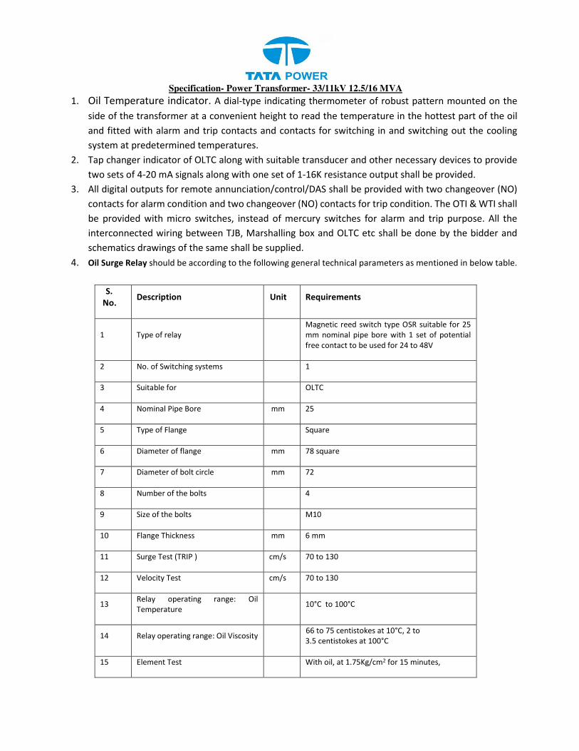
Specification- Power Transformer- 33/11kV 12.5/16 MVA
1. Oil Temperature indicator. A dial-type indicating thermometer of robust pattern mounted on the
side of the transformer at a convenient height to read the temperature in the hottest part of the oil
and fitted with alarm and trip contacts and contacts for switching in and switching out the cooling
system at predetermined temperatures.
2. Tap changer indicator of OLTC along with suitable transducer and other necessary devices to provide
two sets of 4-20 mA signals along with one set of 1-16K resistance output shall be provided.
3. All digital outputs for remote annunciation/control/DAS shall be provided with two changeover (NO)
contacts for alarm condition and two changeover (NO) contacts for trip condition. The OTI & WTI shall
be provided with micro switches, instead of mercury switches for alarm and trip purpose. All the
interconnected wiring between TJB, Marshalling box and OLTC etc shall be done by the bidder and
schematics drawings of the same shall be supplied.
4. Oil Surge Relay should be according to the following general technical parameters as mentioned in below table.
S.
No. Description Unit Requirements
1 Type of relay
Magnetic reed switch type OSR suitable for 25
mm nominal pipe bore with 1 set of potential
free contact to be used for 24 to 48V
2 No. of Switching systems 1
3 Suitable for OLTC
4 Nominal Pipe Bore mm 25
5 Type of Flange Square
6 Diameter of flange mm 78 square
7 Diameter of bolt circle mm 72
8 Number of the bolts 4
9 Size of the bolts M10
10 Flange Thickness mm 6 mm
11 Surge Test (TRIP ) cm/s 70 to 130
12 Velocity Test cm/s 70 to 130
13 Relay operating range: Oil
Temperature 10°C to 100°C
14 Relay operating range: Oil Viscosity
66 to 75 centistokes at 10°C, 2 to
3.5 centistokes at 100°C
15 Element Test With oil, at 1.75Kg/cm2 for 15 minutes,

Specification- Power Transformer- 33/11kV 12.5/16 MVA
16 High Voltage Test
Shall be able to withstand 2000 V at 50 Hz for 1
minute
17 Insulation Resistance Test
Shall be Greater than 10 Mega ohms with 500 V
megger
18 Porosity Test
With oil, at 1.5 kg/cm2 for 4 hours
- There shall not be any leakage or mechanical
damage
19 Mechanical Strength Test With oil at 8 kg/cm2 for 1 minute
20 Resistance of the Switch
Not to exceed 0.1 ohm across the electrodes of
magnetic switch
22 Cable entry in terminal box From bottom side
xxviii) Transformer shall be supplied with all control cable, WTI & OTI, sensing cable, glands, lugs etc
(complete control).
xxix) Radiators shall be complete with motors, fans etc as described in clause 5.10.
xxx) Oil Preserving Equipment
xxxi) Eye bolts and lugs on all parts for ease of handling.
xxxii) Two grounding terminals.
xxxiii) Diagram and rating plate.
xxxiv) One set of equipment for control, protection, indication and annunciation for each transformer
comprising motor contactors, detecting elements or devices, indicating apparatus instruments, relay,
annunciators, etc.
xxxv) Separate tank mounted marshalling box for terminal blocks for current transformer secondary only
with Cable conduits for cables from devices to marshalling box.
xxxvi) Provision shall be made for installing resistance temperature detectors for temperature recording
instruments arranged separately for the following:
a) Hot oil
b) Winding hot spot
xxxvii) Two silica gel breathers (more than 5kg) each of 100% capacity for main tank.
xxxviii) Ladder with ant-climbing arrangement and lock. Ladder should mount on side of transformer and not
on HV/ LV side bushing.
xxxix) Inspection covers for transformer inspections on all phases (on vertical plane)
xl) The equipment and accessories furnished with the transformer shall be suitably mounted on the
transformer for ease of operation, inspection and maintenance, and the mounting details shall be
subject to the approval of the purchaser. All valves shall be provided either with blind companion
flanges or with pipe plugs, for protection. All valves shall have open/close position clearly marked.
Indication, alarm and relay equipment shall have contacts suitable for operation with 24/48V Volts
DC supply. Any other accessories or appliances recommended by the Bidder for the satisfactory

Specification- Power Transformer- 33/11kV 12.5/16 MVA
operation of the transformers shall be supplied
Note:
1. The fittings listed above are indicative and any other fittings which are generally required for
satisfactory operation of the transformer are deemed to be included in the quoted price of the
transformer.
2. The contacts of various devices required for alarm and trip shall be potential free and shall be
adequately rated for continuous, making and breaking current duties as specified.
ANTI RUSTING/ CORROSION TREATMENT
1. The bidder shall ensure that all fabrication i.e. transformer tank, radiators, marshalling boxes and other
accessories are treated for highest quality performance for the entire life of the transformer. The
Bidder shall submit plan for extra measures he is taking for prevention of corrosion, along with the
offer.
2. Finishes on transformer and appurtenant parts, edges (exposed to atmosphere)
3. NO GAS CUT EDGE OR SURFACE shall be acceptable unless smoothly ground to plane surface without
irregular projections and corners (which cannot be blasted to the required roughness).
4. For all radiators the following painting procedure shall be followed. The metal spray (99.95% assay
zinc) to a thickness about 100 microns with surface roughening and two coats of paints with proper
supervision and quality checks. Bidder shall indicate separate price for metal spray of radiators.
5. In this corrosion prevention measure it is imperative that the job is fully monitored for optimizing the
proper conduct of the procedure as given in the various national standards. The coating shall be as per
BS: 2569 (latest revision). The coating requirement shall be to BS: 5493 Gr. SC10Z.
6. The Bidder shall submit a Quality Plan, giving the parameters and checking methods, (major, critical,
minor).
7. The paint shade used shall be shade 631 as per IS:5.
The following shall be the check points for the metal spray of Radiators:-
a) Metal Spray
b) Surface preparation
c) Chemical analysis of actual material used for spray (batch wise identification).
d) Coating Process (the first trial job will be witnessed to see if the written procedure is
followed).
e) Coating thickness test, adhesion test as per BS.
f) Repair area classification major or minor and accordingly the repair from blasting onwards
otherwise.
Bidder may quote for galvanized radiators instead of metal spray radiators as an alternative.
Centre of Gravity

Specification- Power Transformer- 33/11kV 12.5/16 MVA
The centre of gravity of the assembled transformer shall be low and as near the vertical centre line as possible.
The transformer shall be stable with or without oil. If the centre of gravity is eccentric relative to track either
with or without oil, its location shall be shown on the outline drawing.
CENTRAL LINE MARKING
Central line of the transformer, tank, cooler bank, cable box etc. shall be marked properly with indication to
avoid any confusion during installation of the transformer
Painting
1. Before painting, surface preparation shall be done by sand blasting and procedure for sand blasting
has to be submitted by the Vendor along with the bid. The surface preparation for all external surface
prior to painting or coating shall be witnessed by customer or shall be treated as customer hold points.
After sand blasting at all edges Belzona E metal to be applied.
2. Before shipment all steelwork not under oil shall be painted with a primary coat of anti-corrosive paint
of durable nature and two coats of battleship grey paint (Shade 631 of IS:5). Paint shall be epoxy type.
The interior surfaces shall be painted as per bidder’s standard practice. All the paint including primer
shall be applied after testing such as air test, hydraulic test etc. Bidder shall submit their procedure for
painting for Purchaser’s approval, along with the offer.
3. Painting of Marshalling box: Two coats of red oxide primer & two coats of synthetic enameled paint
after chemical treatment.
4. Metal parts not accessible for painting shall be made of corrosion resistant material.
5. Paint shall be as per Indian Standard/International Standard for quality, surface preparation,
application method, thickness check and any other test.
Additional paint shall be supplied along with the transformer for applying touch up paint at site during
installation. The shade of the paint used shall be shade 631 as per IS: 5
NITROGEN INJECTION DRAIN AND STIR SYSTEM
1. Fire prevention and extinguishing system shall work on the oil drain, nitrogen injection and stir
method. The system shall operate during internal fault in transformer or external fire on transformer,
which includes fire due to bursting of transformer bushing and Fire in OLTC tank.
2. Fire detector provided on the transformer shall take minimum time for detection of fire and initiate
the fire protection system on receipt of other required signals.
3. System shall operate on station’s DC auxiliary supply (24/48 VDC). The system shall be capable of
working in Auto/Remote Electrical/Local manual modes.
4. Provision shall be available to keep the system “ISOLATED” /”OUT OF SERVICE” which is necessary for
preventing any mal-operation during transformer maintenance.
5. The protection system shall be compatible of being hooked on to the SCADA or fire alarm system.
Suitable spare contacts shall be made available for operation of fire system. System using PLC shall be
only considered.

Specification- Power Transformer- 33/11kV 12.5/16 MVA
6. Fire protection system shall operate in Auto mode under two logic:
a. In Transformer Explosion prevention Logic it shall operate on receipt of minimum three positive
feedback signals, namely differential relay, pressure relief valve or rapid pressure rise relay or Buccholz
relay and electrical isolation of transformer through master trip relay or HV & LV circuit breaker in
series to avoid any mal-operation of system .
b. In Transformer Fire Prevention logic, Fire protection system shall operate in Auto mode on receipt
of minimum three positive feedback signals, namely fire detector, pressure relief valve or rapid
pressure rise relay or Buchholz relay / OSR (in case of fire in OLTC and electrical isolation of transformer
through master trip relay or HV & LV circuit breaker in series to avoid any mal-operation of system.
c. Provision shall be made in system so that any of the above two logic can be disabled by operator
from local panel only.
d. Supply and installation of Rapid Pressure Rise Relay shall be in the scope of the bidder.
7. Fire protection system shall operate in Remote electrical mode on receipt of signal for electrical
isolation of transformer and by operating switch provided in a box which shall be accessible only after
breaking the glass cover on control panel.
8. The Local manual operating system shall be used only in case if the system fails in Auto mode/ Remote
electrical mode/ power failure. System if kept in manual mode must be clearly visible by a different
alarm / LED.
9. The system shall start operation in auto or remote electrical or local manual, initially draining a pre-
determined quantity of oil from the tank top through outlet valve to reduce the tank pressure and
simultaneously closing Isolation valve in the conservator line and then inject nitrogen gas with
appropriate flow rate at high pressure from lower side of the tank through inlet valves to create stirring
action and reduce the temperature of top oil surface below flash point to extinguish the fire.
10. Isolation valve in the conservator line shall operate mechanically on transformer oil flow rate with
electrical signal for monitoring on control panel. However in case of bursting of transformer bushing
conservator oil should be isolated from main transformer tank without any additional signal to operate
isolation valve.
11. Provision shall be available so that in case of accidental leakage of Nitrogen, the same should not affect
the operation of Transformer.
12. The system shall have built in facility for monitoring or display of the following.
i) Open /Close status of valves.
ii) Healthiness of all sensors.
iii) Operation of PRV
iv) Healthiness of control cable
v) Healthiness of control supply
13. Provision shall be available for annunciation (along with audible alarm) and a mimic panel of the
following.
i) Detection of fire due to external causes
ii) Low nitrogen pressure.
iii) System initiated

Specification- Power Transformer- 33/11kV 12.5/16 MVA
iv) Tank pressure beyond the set limit
v) Operating signal cable faulty.
vi) Operation of conservator isolation valve (PNRV)
vii) Supply failure.
14. However bidder shall confirm whether it is advisable to initiate the system even when transformer is
not electrically isolated due to stuck breaker problem etc.
15. The system shall have built-in-on-line testing facility, which will be operable without affecting the
functioning of the transformer.
16. All valves used in system shall be stainless steel ball / butterfly type and of Legris make or equivalent
as per the purchaser’s approval. Limit switches shall be provided wherever required.
17. The connecting cables shall be fire retardant low smoke (FRLS) armoured cable. Cables passing along
the top of the transformer shall be the fire survival (FS) type.
18. The Pipe Line used for the system shall be of Class ‘C’ type.
19. All the hardware used in the system shall be stainless steel.
20. Limit switches used in the panel shall be of schmersal make or equivalent as per the purchaser’s
approval.
21. Control cable gland used in system shall be of Lapp, Germany make or equivalent as per the
purchaser’s approval.
22. Fire extinguishing cubicle shall be of 3mm thick CRCA sheet with PU painting and IP 55 enclosure
protection class and shall accommodate nitrogen gas cylinder of adequate capacity and associated
accessories like regulator, high pressure tubing etc.
23. The remote control panel, to be mounted inside the control room shall accommodate the necessary
control units, operating switches push buttons etc. and also alarm annunciation unit.
24. The bidder shall, furnish the complete details including bill of materials of the fire prevention and
extinguishing system offered. The list of all accessories including FRLS, fire survival cable, pipes, valves,
sensors, control cubicle, nitrogen gas cylinder etc. shall be listed out and furnished in the offer.
25. The bidder shall ensure that fire prevention and extinguishing system offered is full proof and reliable.
Installation, testing and commissioning of the fire protection system shall also be in the successful
bidder’s scope.
26. Bidder shall ensure that fire prevention and extinguishing system shall not affect the normal operation
of power transformer.
27. Fire protection scheme to the power transformer should have authentic certification regarding
performance similar to one issued by LAPEM (MEXICO)/TAC/RDSO /any other approved standard
laboratory.
28. Similar units offered by bidder shall be in successful operation for a minimum period of two years.
29. The bidder shall also furnish performance certificate for similar systems in proof of the satisfactory
operation.
30. NIDS is to be supplied with transformer unless specified elsewhere in the Bidding document.
31. In All conditions Transformer shall have provision for future implementation of NIDS.
In any condition OEM(PTR) guarantee shall remain the same as mention in “Guarantee” clause

Specification- Power Transformer- 33/11kV 12.5/16 MVA
Surface preparation and painting
1. The paint shall be applied by airless spray.
2. Steel surfaces shall be prepared by shot blast cleaning (IS-9954) to grade Sq.2.5 of ISO 8501-1 or chemical
cleaning including phosphating of the appropriate quality (IS 3618).
3. Heat resistant (Hot oil proof) paint shall be used for the inside surface and whereas for external surface
one coat of thermosetting powder paint or one coat of epoxy primer (zinc chromate) followed by two
coats of polyurethane (P.U.) base paint. as per table given below:
S. No. Paint type
(should be UV restraint,
non-fading)
Area to
be
painted
No of
coats
Total dry film
thickness (min);
micron
1. Thermosetting powder
paint
Inside
Outside
01
01
30
60
2. Liquid Paint
a. Epoxy (primer) Outside 01 30
b. P.U. Paint (finish paint) Outside 02 25 (each)
c. Hot oil resistant paint Inside 01 35
The two coats shall be of oil and weather-resistant nature with final coat as flossy and non-fading paint of
shade 631 as per IS 5 or RAL 7032.
4. The dry film thickness shall not exceed the specified minimum dry film thickens by more than 25%.
5. Any damaged part shall be cleaned to bare metal with an area extending 25 mm around its boundary. A
priming coat shall be immediately applied followed by full paint finish equal to that originally applied and
extending 50 mm around the perimeter of the original damage. The repainted surface shall present a
smooth surface which shall be obtained by carefully chamfering the paint edges before and after priming.
6. Painting shall not affect by weather changes & performance against pilling out or fading etc. to be
guaranteed for 5 Years.
Name plate and marking
1. A stainless steel rating plate, of at least 1 mm thickness, shall be fitted to each transformer in a visible
position and shall carry all the information as specified in the standards.
2. The letters on the rating plate shall be engraved black on the white/silver back ground.
3. Fixing screws for outdoor use shall be of stainless steel or any other corrosion resistant metals.
4. The Name plate shall be embossed with “PO no. with date” & “PROPERTY OF TPCODL”.
5. Danger notice shall have red lettering on a white background or they may be pictorial as approved by
the Purchaser.
The name plate shall contain following information:
a) Type of transformer (Two Winding Transformer)
b) Relevant standard.

Specification- Power Transformer- 33/11kV 12.5/16 MVA
c) Manufacturer’s Name
d) Manufacturer’s Serial No.
e) Year of Manufacture
f) No. of phases
g) Rated kVA
h) Rated frequency
i) Rated Voltage
j) Rated current
k) Connection symbol
l) Percentage impedance voltage at rated current.
m) Type of cooling (ONAN / ONAF).
n) Total Mass.
o) Mass and Volume of insulating Oil.
p) Connection diagram showing the internal connections.
q) Temperature rise
r) Insulation levels of the windings, including neutral end of windings with non-uniform
insulation.
s) Transportation weight
t) Un-tanking weight.
u) Core and windings weight
v) Table giving the tapping voltage, tapping current and tapping power for each tapping.
w) Values of short circuit impedance on the extreme tapings and on the principal tapping and
indication of the winding to which the impedance is related.
x) A table of all guaranteed particulars.
y) Quantity of oil required for normal filling.
z) HV and LV phase to phase clearances.
aa) Vector diagram
bb) Indication of the winding which is fitted with tapping.
cc) Table giving the tapping voltage, the tapping current and the tapping power of each winding,
for each tap.
dd) Value of short circuit impedance on the extreme tapping and on the principal tapping and
indication of the winding to which the impedance is related.
ee) Information of the ability of the transformer to operate at a voltage exceeding 110 % of the
tapping voltage or, for the principal tapping, 110 % of the rated voltage
Valve schedule plate
The name plate shall contain information of all the valves, their locations, quantities and schematic for the
valves
On load tap changer plate
Specification- Power Transformer- 33/11kV 12.5/16 MVA
The name plate shall contain following information:
a) Type
b) S.No.
c) Year of Manufacturing
d) Motor
i. Operating Voltage
ii. Normal Working Current
iii. Max. rated Though current
e) Phase
f) Frequency (Hz)
g) Steps (Numbers)
h) Step Voltage
i) Weight / Volume
i. Tap Changer Without Oil (Kg)
ii. Oil (Kg)
iii. Total
j) Control Voltage (V)
k) Transition resistance (ohms)
Marshalling box
a) Manufacture’s Name.
b) Manufacture’s Serial No.
c) Year of Manufacturing.
d) Purchase Order No.
The following shall be clearly mentioned / Engraved on the Plate: “Property of
TPCODL, Bhubaneswar” Engraved drawing of control circuit, CT / PT circuit and TB
shall be available on Marshalling Box and OLTC Box
Oil filling instruction plate for conservator
The name plate shall contain
a) step wise process for filling oil in conservator
b) Table of fittings with functions
c) Conservator diagram with oil filling process
d) Precautions in detail
7.14 CONTROL CONNECTIONS AND INSTRUMENT AND WIRING TERMINAL BOARD AND FUSES
i) Normally no fuses shall be used anywhere instead of fuses MCB‟s (both in AC & DC circuits) shall
be used. Only in cases where a MCB cannot replace a fuse due to system requirements, a HRC
fuse can be accepted.
ii) All wiring connections, terminal boards, fuses MCB‟s and links shall be suitable for tropical

Specification- Power Transformer- 33/11kV 12.5/16 MVA
atmosphere. Any wiring liable to be in contact with oil shall have oil resisting insulation and the
bare ends of stranded wire shall be sweated together to prevent seepage of oil along the wire.
iii) Panel connections shall be neatly and squarely fixed to the panel. All instruments and panel
wiring shall be run in PVC or non-rusting metal cleats of the compression type. All wiring to a
panel shall be taken from suitable terminal boards.
iv) Where conduits are used, the runs shall be laid with suitable falls, and the lowest parts of the run
shall be external to the boxes. All conduit runs shall be adequately drained and ventilated. Conduits
shall not be run at or below ground level.
v) When 400 volt connections are taken through junction boxes or marshaling boxes, they shall be
adequately screened and 400 volts Danger Notice must be affixed to the outside of the junction
boxes or marshaling box. Proper colour code for Red, Yellow, Blue wires shall be followed.
vi) All box wiring shall be in accordance with relevant ISS. All wiring shall be of stranded copper (48
strands ) of 1100 Volt grade and size not less than 2.5 sq.mm
vii) All wires on panels and all multi-core cables shall have ferrules, for easy identifications, which bear
the same number at both ends, as indicated in the relevant drawing.
viii) At those points of interconnection between the wiring carried out by separate contractors,
where a change of number cannot be avoided double ferrules shall be provided on each wire.
The change of numbering shall be shown on the appropriate diagram of the equipment.
ix) The same ferrule number shall not be used on wires in different circuits on the same panels.
x) Ferrules shall be of white insulating material and shall be provided with glossy finish to prevent the
adhesion of dirt. They shall be clearly and durably marked in black and shall not be affected by
dampness or oil.
xi) Stranded wires shall be terminated with tinned Ross Courtney terminals, claw washers or crimped
tubular lugs. Separate washers shall be suited to the size of the wire terminated. Wiring shall, in
general, be accommodated on the sides of the box and the wires for each circuit shall be separately
grouped. Back of panel wiring shall be arranged so that access to the connecting items of relays
and other apparatus is not impeded.
xii) All circuits in which the voltage exceeds 125 volts, shall be kept physically separated from the
remaining wiring. The function of each circuit shall be marked on the associated terminal
boards.
xiii) Where apparatus is mounted on panels, all metal cases shall be separately earthed by means of
stranded (48 No.) copper wire of strip having a cross section of not less than 2 sq. mm where
strip is used, the joints shall be sweated. The copper wire shall have green coloured insulation for
earth connections.
xiv) All wiring diagram for control and relay panel shall preferably be drawn as viewed from the back
and shall show the terminal boards arranged as in services.
xv) Terminal block rows should be spaced adequately not less than 100 mm apart to permit convenient
access to external cables and terminations.
xvi) Terminal blocks shall be placed with respect to the cable gland ( at a minimum distance of 200

Specification- Power Transformer- 33/11kV 12.5/16 MVA
mm) as to permit satisfactory arrangement of multicore cable tails .
xvii) Terminal blocks shall have pairs of terminals for incoming and outgoing wires. Insulating barriers
shall be provided between adjacent connections. The height of the barriers and the spacing
between terminals shall be such as to give adequate protection while allowing easy access to
terminals. The terminals shall be adequately protected with insulating dust proof covers. No live
metal shall be exposed at the back of the terminal boards. CT terminals shall have shorting
facilities. The terminals for CTs should have provision to insert banana plugs and with isolating
links.
xviii) All interconnecting wiring, as per the final approved scheme between accessories of transformer
and marshaling box is included in the scope of this specification and shall be done by the
Transformer supplier.
xix) The schematic diagram shall be drawn and fixed under a transparent prospane sheet on the inner
side of the marshaling box cover.
xx) To avoid condensation in the Marshaling Box, a space heater shall be provided with an MCB and
thermostat.
xxi) Suitable MV, CFL light shall be provided in the Marshaling Box for lightning purpose.
7.15 RADIO INTERFERENCE AND NOISE LEVEL
Transformers shall be designed with particular care to suppress at least the third and fifth
harmonic voltages so as to minimize interference with communication circuits. Transformer noise
level when energized at normal voltage and frequency shall be as per NEMA stipulations.
8. INSPECTION AND TESTING
(i) The Contractor shall carry out a comprehensive inspection and testing programme during
manufacture of the transformer. This is, however, not intended to form a comprehensive
programme as it is contractor’s responsibility to draw up and carry out such a programme duly
approved by the Employer.
(ii) Transformer of each rating will be as per pre-type tested design.
(iii) The pre-shipment checks shall also be carried out by the contractor.
(iv) The requirements on site tests are as listed in the specifications.
(v) Certified test report and oscillograms shall be furnished to the Employer Consultants for evaluation
as per the schedule of distribution of documents. The Contractor shall also evaluate the test results
and rectify the defects in the equipment based on his and the Employers evaluations of the tests
without any extra charges to the Employer. Manufacturer’s Test Certificates in respect of all
associated auxiliary and ancillary equipment shall be furnished.
(vi) The bidder shall state in his proposal the testing facilities available at his works. In case full testing
facilities are not available, the bidder shall state the method proposed to be adopted so as to
ascertain the transformer characteristics corresponding to full capacity.

Specification- Power Transformer- 33/11kV 12.5/16 MVA
8.1 INSPECTION
Transformers not manufactured as per Type- Tested design shall be rejected.
I. Tank and Conservator
a) Inspection of major weld.
b) Crack detection of major strength weld seams by dye penetration test.
c) Check correct dimensions between wheels, demonstrate turning of wheels, through 900 and further
dimensional check.
d) Leakage test of the conservator.
II. Core
a) Sample testing of core materials for checking specific loss, properties, magnetization characteristics
and thickness.
b) Check on the quality of varnish if used on the stampings.
c) Check on the amount of burrs.
d) Visual and dimensional check during assembly stage.
e) Check on completed core for measurement of iron loss, determination of maximum flux density,
f) Visual and dimensional checks for straightness and roundness of core, thickness of limbs and suitability
of clamps.
g) High voltage DC test (2 KV for one minute) between core and clamps.
Please refer to “Check-list for Inspection of Prime quality CRGO for Transformers” attached at Annexure-A.
It is mandatory to follow the procedure given in this Annexure.
iii) Insulating Material
a) Sample check for physical properties of materials.
b) Check for dielectric strength
c) Check for the reaction of hot oil on insulating materials.
iv) Winding
a) Sample check on winding conductor for mechanical and electrical conductivity.
b) Visual and dimensional checks on conductor for scratches, dent mark etc.
c) Sample check on insulating paper for PH value, electric strength.
d) Check for the bonding of the insulating paper with conductor.
e) Check and ensure that physical condition of all materials taken for windings is satisfactory and
free of dust.
f) Check for absence of short circuit between parallel strands.
v) Checks Before Drying Process
a) Check condition of insulation on the conductor and between the windings.

Specification- Power Transformer- 33/11kV 12.5/16 MVA
b) Check insulation distance between high voltage connections, between high voltage connection cables
and earth and other live parts.
c) Check insulating distances between low voltage connections and earth and other parts.
d) Insulating test for core earthing.
vi) Check During Drying Process
a) Measurement and recording of temperature and drying time during vacuum treatment.
b) Check for completeness of drying
vii) Assembled Transformer
a) Check completed transformer against approved outline drawing, provision for all fittings, finish level
etc.
b) Jacking test on the assembled Transformer.
viii) Oil all standard tests in accordance with IS: 335 shall be carried out on Transformer oil sample
before filling in the transformer.
ix) Test Report for bought out items: The contractor shall submit the test reports for all bought out /
sub contracted items for approval.
a) Buchholz relay
b) Sudden pressure rise relay on Main Tank
c) Winding temperature indicators
d) Oil temperature indicators
e) Bushings
f) Marshaling box
g) On/Off Load Tap changer as per BOQ
h) Any other item required to complete the works.
i) Porcelain, bushings, winding coolers, control devices, insulating oil and other associated
equipment shall be tested by the contractor in accordance with relevant IS . If such requirement
is purchased by the contractor on a sub-contract, he shall have them tested to comply with these
requirements.
8.2 FACTORY TESTS
i) All standards routine tests in accordance IS: 2026 with dielectric tests corresponding as per latest
amendments to IS: 2026 shall be carried out.
ii) All routine, acceptance & type tests shall be carried out in accordance with the relevant IS/IEC. All
routine/acceptance tests shall be witnessed by the purchaser/his authorized representative. All the
components and fittings shall also be type tested as per the relevant standards. Following tests shall
be necessarily conducted on the Power Transformers in addition to others specified in IS/IEC
standards. Test for the OLTC shall be done as per the IS 8468

Specification- Power Transformer- 33/11kV 12.5/16 MVA
iii) All auxiliary equipment shall be tested as per the relevant IS. Test certificates shall be submitted for
bought out items.
iv) High voltage withstand test shall be performed on auxiliary equipment and wiring after complete
assembly.
v) Following additional routine tests shall also be carried out on each transformer:
a) Magnetic Circuit Test Each core shall be tested for 1 minute at 2000 Volt AC
b) Oil leakage test on transformer
8.2.1 Type Test
8.2.1.1 The measurements and tests should be carried out in accordance with the standard specified in
each case as indicated in the following table if the same tests were not conducted earlier at CPRI
or any NABL accredited Laboratory on the transformers of the offered design without any cost
implication on employer.
8.2.1.2 Transformer type tests
Type Test Standard
Temperature Rise Test IEC 76/IS 2026/IS6600
Impulse Volt age Withstand Test, including Full
Waves and Chopped Waves as listed below
IEC 76/IS 2026
Noise Level Measurement IEC 551
In accordance with IEC 76-3 the following sequence of impulses should have been/ should be
applied;
• One full wave at 50% BIL;
• One full wave at 100% BIL;
• One chopped wave at 50% BIL
• Two chopped waves at 100% BIL and
• Two full waves at 100% BIL.
The type tests to be carried out by the Bidder shall include but not limited to the following:
1. Measurement of winding resistance.
2. Measurement of voltage ratio and check of voltage vector relationship.
3. Measurement of impedance voltage / short-circuit impedance (Principal tapping) and load loss.
4. Measurement of no load loss and current.
5. Measurement of insulation resistance.
6. Dielectric Test.
7. Temperature rise for determining the maximum temperature rise after continuous full load run. The ambient
temperature and time should be stated in the test certificate.

Specification- Power Transformer- 33/11kV 12.5/16 MVA
8. Tests on on-load tap-changer.
9. Short Circuit withstand test
10. Test to verify IP55 of Marshalling and cable boxes.
11. Lightning Impulse voltage test with chopped wave.
Note: The bidder shall submit the test report from CPRI or ERDA for g, i and k of the above mentioned.
Following type tests shall be carried out on one transformer of each rating, at the works of the bidder, in presence of
Purchaser’s representative.
1. Temperature rise test including DGA (DGA shall be done before & after the heat run test).
2. Impulse Test (Including chopped wave on all the three limbs of HV & LV).
The NIDS shall be subjected to the operational test at manufacturing works of Nitrogen Injection Fire
Prevention and extinguishing system in presence of Purchaser’s representative. The manufacture’s test
certificates of various accessories of NIDS shall be furnished at the time of Inspection to the inspecting officer.
8.2.1.3 If the type test report(s) submitted by the bidder do not fulfill the criteria, as stipulated in this
technical specification/ Bidder’s offer, the relevant type test(s) has/ have to be conducted by the
Bidder at his own cost in CPRI/ NABL accredited laboratory in the presence of employers
representative(s) without any financial liability to employer in the event of order placed on him.
8.2.1.4 The offered transformer must be manufactured as per type tested design. A copy of type test
certificate must be submitted by manufacturer to Engineer/Employer. Transformers offered
without type tested however design shall not be accepted. In case manufacturer agrees for type
testing of transformers, testing shall be conducted on manufacturer’s cost. No claim shall be
acceptable towards type testing. The transformers shall be accepted only on acceptance of type
testing results by employer.
8.2.1.5 The supplier shall furnish calculations in accordance with IS: 2026 to demonstrate the Thermal
ability of the transformers to withstand Short Circuit forces.
8.2.1(A) Special Test
The short circuit test shall be a mandatory test for each design shall be supplied by the manufacturer
and no exception shall be allowed. The test shall be conducted as per latest standard tabled below:
The following tests shall be carried out by mutual agreement between the purchaser and the bidder.
All Tests shall be done as per the relevant standard. Test certificates shall be submitted for bought
out items. High voltage withstand test shall be performed on auxiliary equipment and wiring after
complete assembly.
Short Circuit Test IEC 76 / IS 2026

Specification- Power Transformer- 33/11kV 12.5/16 MVA
a) Measurement of the harmonics of the No-Load Current.
b) Determination of transient voltage transformer characteristics.
c) Measurement of insulation resistance to earth of the windings, and / or measurement of
Dissipation factor (tan δ) of the insulation system capacitances.( Theses are reference
values for comparison with later measurement in the field. No limitation for the values are
given here.).
d) Lightning impulse test on Neutral terminals.
e) Long duration induced AC voltage test (ACLD) transformer winding 72.5 <Um≤ 170kV.
f) Magnetic circuit (isolation) test.
g) SFRA Test.
8.2.2 Stage Inspection
The supplier shall offer the core, windings and tank of each transformer for inspection by the
Employers representative(s). During stage Inspection, all the measurements like diameter, window
height, leg Centre, stack width, stack thickness, thickness of laminations etc. for core assembly,
conductor size, Insulation thickness, I.D., O.D, winding height, major and minor insulations for
both H.V and L.V windings, length, breadth, height and thickness of plates of Transformer tank,
the quality of fittings and accessories will be taken / determined. The supplier can offer for final
inspection of the transformers subject to clearance of the stage Inspection report by the Employer.
8.2.3 Routine Tests
Transformer routine tests shall include tests stated in latest issue of IS: 2026 (Part –1). These tests
shall also include but shall not be limited to the following:
(i) Measurement of winding DC resistance.
(ii) Voltage ratio on each tapping and check of voltage vector relationship.
(iii) Impedance voltage at all tapping’s.
(iv) Magnetic circuit test as per relevant ISS or CBIP manual or latest standard being followed.
(v) Measurement of Load losses at normal tap and extreme taps.
(vi) No load losses and no load current at rated voltage and rated frequency, also at 25% to 120 %
of rated voltage in steps.
(vii) Absorption index i.e insulation resistance for 15 seconds and 60 seconds (R 60/ R 15 ) and
polarization index i.e Insulation Resistance for 10 minutes and one minute (R 10 mt / R 1 mt).
(viii) Induced over voltage withstand test.
(ix) Separate source voltage withstand test.
(x) Tan delta measurement and capacitance of each winding to earth (with all other windings
earthed) & between all windings connected together to earth.
(xi) Measurement of zero sequence impedance
(xii) Tests on On/Off Load Tap changer as per BOQ (fully assembled on transformer) as per IS 2026
(xiii) Auxiliary circuit tests
(xiv) Oil BDV tests

Specification- Power Transformer- 33/11kV 12.5/16 MVA
(xv) Measurement of neutral unbalance current which shall not exceed 2% of the full rated current
of the transformer.
(xvi) Magnetic balance test
(xvii) Leakage test.
Sr.
No.
Test to be done Reference BIS Clause no.
1 Measurement of Winding Resistance IS 2026 (Part 1) 16.2.1 &
16.2..3
2 Measurement of voltage ratio, polarity and vector
group check
IS 2026 (Part 1)
16.3, 8.6,
8.7
3 Measurement of short impedance and load loss
at 50% and 100% load
IS 2026 (Part 1) 16.4
4 Measurement of no load losses and magnetizing
current at rated frequency and 90%, 100% and
112.5% of rated voltage
IS 2026 (Part 1) 16.5
5 Measurement of insulation resistance IS 2026 (Part 1) 16.6
6 Dielectric Test. IS : 2026 (Part
III)-2009
7 Test on -Load Tap Changer. IS : 2026-2011
(Part I)
10.8
8 Measurement of Zero-sequence impedance on
three phase transformer.
IS : 2026-2011
(Part I)
3.7.3
9 Bushing shall be tested for Capacitance and Power
factor and shall meet the manufacture’s
requirement.
IS : 2026 (Part
III)
10
10 All CTs and resistance of image coil for winding
temperature indicator shall be checked for ratio
test, polarity and knee point voltage test.
11 Determination of Capacitances and dissipation
factor winding-to-earth and between windings.
12 Magnetic balance test.
13 Measurement of Magnetizing current at low
voltage.
14 Vacuum withstand test on tanks and radiators.
15 The total Losses shall comprise of the No Load
Losses, Load Losses (I²R loss + stray loss) and
Auxiliary Losses at rated output duly converted at
75 °C average winding temperature and shall also
be indicated in the test report. Load loses shall be
that corresponding to rated load on HV, LV
windings.
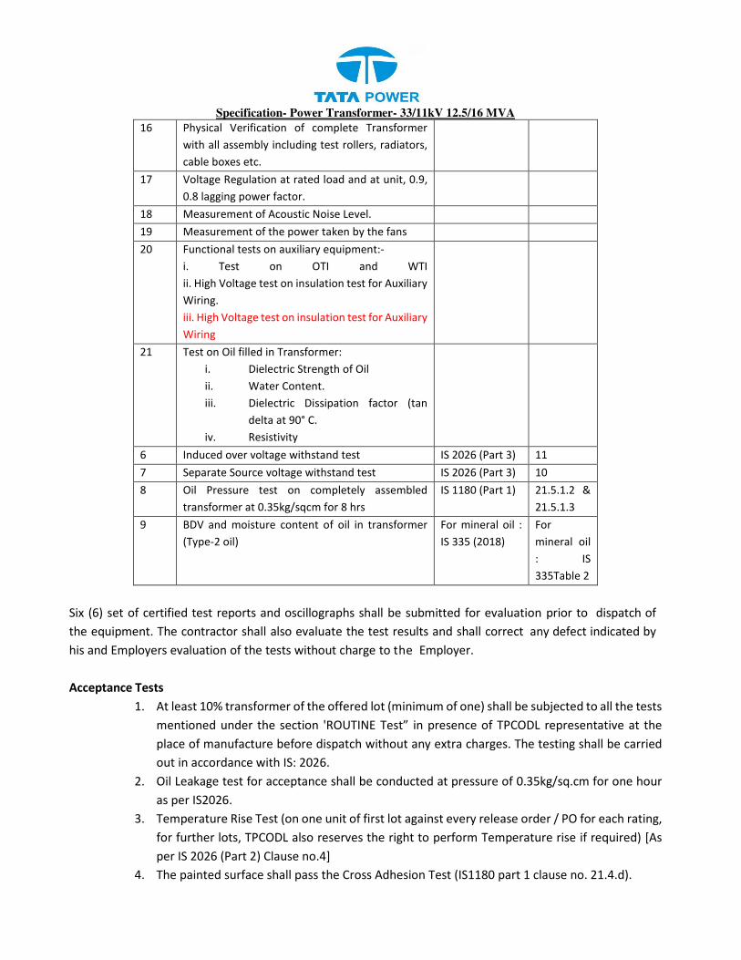
Specification- Power Transformer- 33/11kV 12.5/16 MVA
16 Physical Verification of complete Transformer
with all assembly including test rollers, radiators,
cable boxes etc.
17 Voltage Regulation at rated load and at unit, 0.9,
0.8 lagging power factor.
18 Measurement of Acoustic Noise Level.
19 Measurement of the power taken by the fans
20 Functional tests on auxiliary equipment:-
i. Test on OTI and WTI
ii. High Voltage test on insulation test for Auxiliary
Wiring.
iii. High Voltage test on insulation test for Auxiliary
Wiring
21 Test on Oil filled in Transformer:
i. Dielectric Strength of Oil
ii. Water Content.
iii. Dielectric Dissipation factor (tan
delta at 90° C.
iv. Resistivity
6 Induced over voltage withstand test IS 2026 (Part 3) 11
7 Separate Source voltage withstand test IS 2026 (Part 3) 10
8 Oil Pressure test on completely assembled
transformer at 0.35kg/sqcm for 8 hrs
IS 1180 (Part 1) 21.5.1.2 &
21.5.1.3
9 BDV and moisture content of oil in transformer
(Type-2 oil)
For mineral oil :
IS 335 (2018)
For
mineral oil
: IS
335Table 2
Six (6) set of certified test reports and oscillographs shall be submitted for evaluation prior to dispatch of
the equipment. The contractor shall also evaluate the test results and shall correct any defect indicated by
his and Employers evaluation of the tests without charge to the Employer.
Acceptance Tests
1. At least 10% transformer of the offered lot (minimum of one) shall be subjected to all the tests
mentioned under the section 'ROUTINE Test” in presence of TPCODL representative at the
place of manufacture before dispatch without any extra charges. The testing shall be carried
out in accordance with IS: 2026.
2. Oil Leakage test for acceptance shall be conducted at pressure of 0.35kg/sq.cm for one hour
as per IS2026.
3. Temperature Rise Test (on one unit of first lot against every release order / PO for each rating,
for further lots, TPCODL also reserves the right to perform Temperature rise if required) [As
per IS 2026 (Part 2) Clause no.4]
4. The painted surface shall pass the Cross Adhesion Test (IS1180 part 1 clause no. 21.4.d).

Specification- Power Transformer- 33/11kV 12.5/16 MVA
5. At stage inspection -Checking of weight, dimensions, fitting and accessories, tank sheet
thickness, oil quantity, material finish and workmanship, physical verification of core coil
assembly and measurement of flux density on one unit of each rating of the offered lot with
reference to the GTP and contract drawings.
6. At Final inspection, the incoming raw material and its movement/consumption record in the
related jobs of TPCODL will be verified by inspecting officer. In case of any deviation or non-
availability of such records, the offered lot may get rejected.
The format of final inspection as per annexure
Further tests
The purchaser reserves the right of having any other reasonable tests carried out at his own expense either
before shipment, or at site to ensure that the transformer complies with the requirements of this
specification.
8.2.4 TANK TESTS
a) Oil leakage Test :
The tank and oil filled compartments shall be tested for oil tightness completely filled with air or oil of viscosity
not greater than that of insulating oil conforming to IS : 335 at the ambient temperature and applying a
pressure equal to the normal pressure plus 35 KN/ m2 measured at the base of the tank. The pressure shall
be maintained for a period of not less than 12 hours of oil and one hour for air and during that time no leak
shall occur.
b) Pressure Test
Where required by the Employer, one transformer tank of each size together with its radiator, conservator
vessel and other fittings shall be subjected to a pressure corresponding to twice the normal head of oil or to
the normal pressure plus 35 KN / m2 whichever is lower, measured at the base of the tank and maintained
for one hour.
c) Vacuum Test
One transformer tank of each size shall be subjected to the vacuum pressure of 60 mm of mercury.
The tanks designed for full vacuum shall be tested at an internal pressure of 3.33 KN/m2 (25 mm of
mercury) for one hour. The permanent deflection of flat plates after the vacuum has been released shall
not exceed the value specified in C.B.I.P. Manual on Transformers (Revised 1999) without affecting the
performance of the transformer.
8.3 PRE-SHIPMENT CHECK AT MANUFACTURERS WORKS
i) Check for proper packing and preservation of accessories like radiators, bushings, explosions
vent, dehydrating breather, rollers, buchholz relay, control cubicle connecting pipes and
conservator etc.
ii) Check for proper provision of bracing to arrest the movement of core and winding assembly

Specification- Power Transformer- 33/11kV 12.5/16 MVA
inside the tank.
iii) Gas tightness test to conform tightness.
1. Equipment shall be subject to inspection by a duly authorized representative of the Purchaser.
Inspection may be made at any stage of manufacture at the option of the purchaser and the equipment
if found unsatisfactory as to workmanship or material, the same is liable to rejection.
2. Bidder shall grant free access to the places of manufacture to Purchaser’s representatives at all times
when the work is in progress.
3. Inspection by the Purchaser or its authorized representatives shall not relieve the supplier of his
obligation of furnishing equipment in accordance with the specifications.
4. Material shall be dispatched after specific MDCC (Material Dispatch Clearance Certificate) is issued by
Purchaser.
Following documents shall be sent along with material:
a) Test reports
b) MDCC issued by TPCODL
c) Invoice in duplicate
d) Packing list
e) Drawings & catalogue
f) Guarantee / Warrantee card
g) Delivery Challan
h) Other Documents (as applicable)
5. In respect of raw material such as core stampings, winding conductors, insulating paper and oil, bidder
shall use materials manufactured/supplied by standard manufacturers and furnish the manufacturers’
test certificate as well as the proof of purchase from these manufacturers (excise gate pass) for
information of the purchaser. The bidder shall furnish following documents along with their offer in
respect of the raw materials:
a) Invoice of supplier.
b) Mill’s certificate
c) Packing List.
d) Bill of Landing
e) Bill of entry certificate by custom
6. After the main raw-material i.e. core and coil material and tanks are arranged and transformers are
taken for production on the shop floor, to ensure the quality of transformers, the inspection shall be
carried out by the purchase’s representative at following stages:
i. Stage Inspection I – Bidder has to facilitate for stage inspection of Tank, HV and LV windings
and Core of the offered transformers. Bidder has to facilitate for stage inspection of Tank, HV
and LV windings in one inspection call without any extra charges. Multiple inspections calls for
stage inspection-I will not be considered and the delay will be accountable at bidder end. At

Specification- Power Transformer- 33/11kV 12.5/16 MVA
this stage checking of weights, dimensions, tank sheet thickness, Pressure and vacuum test
and quality of material, finish & workmanship as per GTP/QA plan and approved drawings.
During stage inspection TPCODLreserves the rights to dismantle the assembled core to ensure
that the CRGO laminations used are of good quality.
ii. Stage inspection II – Bidder has to facilitate for stage inspection -II for Core coil assembly of
the offered transformers in without any extra charges. The testing shall be carried out in
accordance with IS : 2026 and as per GTP/QA plan/Drawing.
Note: For Stage inspection, Annexure –II will be referred.
iii. Final Inspection - Bidder has to facilitate for final inspection once the offered transformer is
ready for dispatch. Inspection will be done as per w.r.t tests mentioned in Clause 7.2 and
inspection test plan format in Annexure-III.
7. To ascertain the quality of the transformer oil, the original manufacturer’s tests report shall be
submitted at the time of inspection. Arrangements shall also be made for testing of transformer oil,
after taking out the sample from the manufactured transformers and tested in the presence of
purchaser’s representative.
8. The Bidder shall intimate the purchaser in advance for inspection, so that an officer for carrying out
inspection could be deputed, as far as possible within 07days (Within Bhubaneswar)/ 12Days (outside
Bhubaneswar) from the date of intimation.
9. Further, about the readiness of the transformers, for final inspection for carrying out tests as per
relevant IS/IECs shall be sent by the Bidder along with routine test certificates. The inspection shall
normally be arranged by the purchaser at the earliest after receipt of offer for pre-delivery inspection.
10. In case of any defect/ defective workmanship observed at any stage by the purchaser’s Inspecting
officer, the same shall be pointed out to the Bidder in writing for taking remedial measures. Further
processing shall only be done after clearance from the inspecting officer / purchaser.
11. All tests and inspection shall be carried out at the place of manufacture unless otherwise specifically
agreed upon by the manufacturer and purchaser at the time of purchase/tender.
12. The manufacturer shall offer the inspector representing the Purchaser all reasonable facilities, without
charges, to satisfy him that the material is being supplied in accordance with this specification. This
will include Stage Inspection during manufacturing stage as well as during Acceptance Tests.
13. The bidder shall provide all services to establish and maintain quality of workmanship in his works and
to ensure the mechanical / electrical performance of components, compliance with drawings,
identification and acceptability of all materials, parts and equipment as per latest quality standards of
ISO 9000.
The Purchaser has the right to have the test carried out at his own by an independent agency wherever there
is a dispute regarding the quality supplied. Purchaser has right to test 1% of the supply selected either from
the stores or field to check the quality of the product. In case of any deviation purchaser have every right to
reject the entire lot or penalize the bidder, which may lead to blacklisting, among other things

Specification- Power Transformer- 33/11kV 12.5/16 MVA
8.4 INSPECTION AND TESTING AT SITE
On receipt of transformer at site, shall be performed detailed inspection covering areas right
from the receipt of material up to commissioning stage. An indicative program of inspection as
envisaged by the Engineer is given below.
8.4.1 Receipt and Storage Checks
i) Check and record conditions of each package visible parts of the transformers etc for any
damage.
ii) Check and record the gas pressure in the transformer tank as well as in the gas cylinder.
iii) Visual check of core and coils before filling up with oil and also check condition of core and
winding in general.
iv) The material received at Purchaser’s store shall be inspected for acceptance and shall be liable for
rejection, if found different from the reports of the pre-dispatch inspection and one copy of the report
shall be sent to Project Engineering department.
v) In case the transformers proposed for supply against the order are not exactly as per the tested
design, the Bidder shall be required to carry out the short circuit test and impulse voltage withstand
test at its own cost in the presence of the representative of the Purchaser. The supply shall be
accepted only after such test is done successfully, as it confirms on successful withstand of short
circuit and healthiness of the active parts thereafter on un-tanking after a short circuit test. Apart
from dynamic ability test, the transformers shall also be required to withstand thermal ability test or
thermal withstand ability will have to be established by way of calculations.
vi) The Purchaser reserves the right to conduct all tests on Transformer after arrival at site / stores and
the manufacturer shall guarantee test certificate figures under actual service conditions.
vii) The Purchaser reserves the right to conduct short circuit test and impulse voltage withstand test in
accordance to IS, afresh on each ordered rating at purchaser cost, even if the transformer of the same
rating and similar design are already tested. This test shall be carried out on a transformer to be
selected by the purchaser either at the manufacturer’s works when they are offered in a lot for supply
or randomly from the supplies already made to purchaser’s stores. The findings and conclusions of
these tests shall be binding on the bidder.
viii) Test at TPCODLstore/Site: after receipt of transformers at TPCODLstores/Site, following minimum
tests will be carried out.
a) Total weight of the transformer. (It should be as per the offer, subjected to tolerance as per
approved drawings & GTPs).
b) Oil level in the transformer
c) Verifications of all the fittings.
d) Physical verification of all the transformers for any damages, oil leakage, quality of painting etc.
ix) Test at site: The purchaser reserves the right to conduct all tests on Transformer after arrival at
site/stores and the manufacturer shall guarantee test certificate figures under actual service
conditions.

Specification- Power Transformer- 33/11kV 12.5/16 MVA
Shock/impact recorder data analysis to be submitted by bidder to ascertain the concealed damage if any
during transportation/movement of transformer.
8.4.2 Installation Checks
i) Inspection and performance testing of accessories like tap changers etc.
ii) Check choking of the tubes of radiators
iii) Test on oil samples taken from main tank top and bottom and cooling system. Samples should be
taken only after the oil has been allowed to settle for 24 hours.
iv) Check the whole assembly for tightness, general appearance etc.
v) Oil leakage tests.
8.4.3 Pre-Commissioning Tests
After the transformer is installed, the following pre-commissioning tests and checks shall be done before
putting the transformer in service.
i) Megger Test
ii) Phase relationship test ( Vector group test )
iii) Buchholz relay alarm & surge operation test (Physical)
iv) Ratio test on all taps
v) Low oil level ( in conservator ) alarm
vi) Temperature Indicators (Physical)
vii) Marshaling kiosk (Physical)
8.4.4 The following additional checks shall be made:
i) All oil valves are incorrect position closed or opened as required
ii) All air pocket are cleared.
iii) Thermometer pockets are filled with oil
iv) Oil is at correct level in the bushing, conservator, diverter switch & tank etc.
v) Earthing connections are made.
vi) Bushing arcing horn is set correctly and gap distance is recorded.
vii) C T polarity and ratio is correct.
8.5 PERFORMANCE
The performance of the transformer shall be measured on the following aspects.
i) The transformer shall be capable of being operated without danger on any tapping at the rated
KVA with voltage variations and ± 10% corresponding to the voltage of the tapping
ii) Radio interference and Noise Level
iii) The transformer shall be designed with particular attention to the suppression of third and fifth
harmonics so as to minimize interference with communication circuits.
iv) The all accessories of transformer viz. OTI, WTI, buchholz relay, etc. shall be SCADA compatible.

Specification- Power Transformer- 33/11kV 12.5/16 MVA
8.6 FAULT CONDITIONS
a) The transformer shall be capable of withstanding for two(2) seconds without damages any
external short circuit to earth
b) Transformer shall be capable of withstanding thermal and mechanical stresses conveyed by
symmetrical or asymmetrical faults on any winding. This shall be demonstrated through calculation
as per IS : 2026.
c) Transformer shall accept, without injurious heating, combined voltage and frequency fluctuation
which produce the 125% over fluxing condition for one minute and 140% for 5 seconds.
8.7 WITNESSING OF TESTS AND EXCESSIVE LOSSES
The Employer reserves the right to reject the Transformer if losses exceed the maximum specified
as per Clause No 2. SPECIFIC TECHNICAL REQUIREMENTS (STANDARD CONDITIONS), item-35of
this specification or if temperature rise of oil and winding exceed the values specified at item -26 of
the above clause.
9. LIQUIDATED DAMAGES FOR EXCESSIVE LOSSES
There is no positive tolerance on the guaranteed losses offered by the bidder. However, the
transformer(s) shall be rejected out rightly, if any of the losses i.e. no load loss or load loss or both
exceed (s) the guaranteed maximum permissible loss figures quoted by the bidder in the Technical
Data Schedule with the bid.
10. SPARE PARTS
In case the manufacturer goes out of production of spare parts, then he shall make available the
drawings of spare parts and specification of materials at no extra cost to the Employer to
fabricate or procure spare parts from other sources.
Mandatory Spare Parts
The suppliers shall provide the following mandatory spare s for each of Transformer supplied
1. H.V. & L.V. Bushing & Studs –Each 2 Nos
2. Bimetallic connector for H.V & L.V. Bushings – Each 2 sets
10.1 INSTRUCTION MANUAL
Eight sets of the instruction manuals shall be supplied at least four (4) weeks before the actual
dispatch of equipment. The manuals shall be in bound volumes and shall contain all the drawings
and information required for erection, operation and maintenance of the transformer. The
manuals shall include amongst other, the following particular:
a) Marked erection prints identifying the components, parts of the transformer as dispatched with
assembly drawings.
b) Detailed dimensions, assembly and description of all auxiliaries.
c) Detailed views of the core and winding assembly, winding connections and tapings tap changer
construction etc. These drawings are required for carrying out overhauling operation at site.

Specification- Power Transformer- 33/11kV 12.5/16 MVA
d) Salient technical particulars of the transformer.
e) Copies of all final approved drawings.
f) Detailed O&M instructions with periodical check lists and Performa etc.
10.2 COMPLETENESS OF EQUIPMENT
All fittings and accessories, which may not be specifically mentioned in the specification but
which are necessary for the satisfactory operation of the transformer, shall be deemed to be
included in the specification and shall be furnished by the supplier without extra charges. The
equipment shall be complete in all details whether such details are mentioned in the specification
or not, without any financial liability to the Employer under any circumstances.
11. COMMISSIONING
The utility will give a 10 days’ notice to the supplier of transformer before commissioning. The
manufacturer will depute his representative to supervise the commissioning. In case, the
manufacturer fails to depute his representative, the utility will go ahead with the commissioning and
under these circumstances, it would be deemed that commissioning is done as per recommendations
of manufacturer.
Packing
1. Bidder shall ensure that all the equipment covered under this specification shall be prepared for
rail/road transport in a manner so as to protect the equipment from damage in transit.
2. The packing may be in accordance with the bidder’s standard practice but he should give full
particulars of packing for the approval of the purchaser. Special arrangement should be made to
facilitate handling and to protect the projecting connections from damage in transit.
3. The transformer shall be shipped filled with oil/without oil but with the tank filled with Nitrogen under
pressure complete with gas cylinder reducer, connection and pressure gauges. (After testing dew point
of the Nitrogen filled. Dispatch clearance will be given only after achieving satisfactory dryness i.e. dew
point measurement results). These accessories will be part of purchase. However, if neutral grounding
transformer and reactors are included in the scope, these can be transported with oil. (Whichever way
desired by the purchaser depending on the size etc.)
4. Provisions for monitoring of oil and gas pressure during transport and storage and a make-up Nitrogen
cylinder shall be made.
5. A shock recorder also shall be provided during transport.
6. Bushings shall be packed in proper containers for transport.
7. All parts shall be adequately marked to facilitate field erection.
8. Boxes and crates shall be marked with the contract number and shall have a packing list enclosed
showing the parts contained therein.
9. Unloading, dragging of transformer up to 50 meters & keeping it on foundation at TPCODL site/stores
will be in the scope of supplier. The bidder shall take care of this point while quoting the rates for
Freight & Insurance charges.

Specification- Power Transformer- 33/11kV 12.5/16 MVA
10. Impact recorder to be mounted on the transformer at strategic locations after discussing with
purchaser so that any impact due to transportation can be recorded and accordingly necessary action
can be taken. Suitable software and diagnosis tool to be provided that of impact recorder.
Note: One use plastic not to be used for packing of the material
12. GUARANTEE
The manufacturers of the transformer shall provide a guarantee of 60 months from the date of receipt
of transformer at the stores of the Utility. In case the transformer fails within the guarantee period,
the supplier will depute his representative within 15 days from date of intimation by the utility for
joint inspection. In case, the failure is due to the reasons attributed to supplier, the transformer will
be replaced/repaired by the supplier within 2 months from the date of joint inspection.
1. Bidder shall stand guarantee towards design, materials, workmanship & quality of process/
manufacturing of items under the contract for due and intended performance of the same, as an
integrated product delivered under this contract.
2. In the event any defect is found by the Purchaser up to a period of 48 months from the date of
commissioning or 60 months from the date of last supplies made under the contract, whichever is
earlier.
3. Bidder shall be liable to undertake to replace/rectify such defects at his own costs, within mutually
agreed timeframe, and to the entire satisfaction of the Purchaser, failing which the Purchaser will be
at liberty to get it replaced/rectified at Bidder’s risks and costs and recover all such expenses plus the
Purchaser’s own charges (@ 20% of expenses incurred), from the Bidder or from the “Security cum
Performance Deposit” as the case may be.
4. In case of Two Winding Power Transformer fails within the guarantee period the purchaser will
immediately inform the Bidder who shall take back the failed Two Winding Power Transformer within
15 days from the date of intimation at his own cost and replace / repair the transformer within forty
five days of date of intimation with a roll over guarantee.
The outage period i.e. period from the date of failure till unit is repaired / replaced shall not be
counted for arriving at the guarantee period.
Bidder shall further be responsible for ‘free replacement’ for another period of THREE years from the
end of the guarantee period for any ‘Latent Defects’ if noticed and reported by the Purchaser
Quality control
1. The bidder shall submit with the offer Quality assurance plan indicating the various stages of
inspection, the tests and checks which will be carried out on the material of construction, components
during manufacture and bought out items and fully assembled component and equipment after
finishing.
2. As part of the plan, a schedule for stage and final inspection within the parameters of the delivery
schedule shall be furnished.
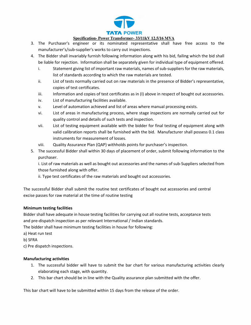
Specification- Power Transformer- 33/11kV 12.5/16 MVA
3. The Purchaser's engineer or its nominated representative shall have free access to the
manufacturer’s/sub-supplier's works to carry out inspections.
4. The Bidder shall invariably furnish following information along with his bid, failing which the bid shall
be liable for rejection. Information shall be separately given for individual type of equipment offered.
i. Statement giving list of important raw materials, names of sub-suppliers for the raw materials,
list of standards according to which the raw materials are tested.
ii. List of tests normally carried out on raw materials in the presence of Bidder’s representative,
copies of test certificates.
iii. Information and copies of test certificates as in (I) above in respect of bought out accessories.
iv. List of manufacturing facilities available.
v. Level of automation achieved and list of areas where manual processing exists.
vi. List of areas in manufacturing process, where stage inspections are normally carried out for
quality control and details of such tests and inspection.
vii. List of testing equipment available with the bidder for final testing of equipment along with
valid calibration reports shall be furnished with the bid. Manufacturer shall possess 0.1 class
instruments for measurement of losses.
viii. Quality Assurance Plan (QAP) withholds points for purchaser’s inspection.
5. The successful Bidder shall within 30 days of placement of order, submit following information to the
purchaser.
i. List of raw materials as well as bought out accessories and the names of sub-Suppliers selected from
those furnished along with offer.
ii. Type test certificates of the raw materials and bought out accessories.
The successful Bidder shall submit the routine test certificates of bought out accessories and central
excise passes for raw material at the time of routine testing
Minimum testing facilities
Bidder shall have adequate in house testing facilities for carrying out all routine tests, acceptance tests
and pre-dispatch inspection as per relevant International / Indian standards.
The bidder shall have minimum testing facilities in house for following:
a) Heat run test
b) SFRA
c) Pre dispatch inspections.
Manufacturing activities
1. The successful bidder will have to submit the bar chart for various manufacturing activities clearly
elaborating each stage, with quantity.
2. This bar chart should be in line with the Quality assurance plan submitted with the offer.
This bar chart will have to be submitted within 15 days from the release of the order.

Specification- Power Transformer- 33/11kV 12.5/16 MVA
Spares accessories and tools
1. Bidder shall provide a list of recommended spares with quantity and unit prices for 5 years of operation
after commissioning.
2. The Purchaser may order all or any of the spare parts listed at the time of contract award and the spare
parts so ordered shall be supplied as part of the definite works.
3. The Purchaser may order additional spares at any time during the contract period at the rates stated
in the Contract Document.
4. Bidder shall give an assurance that spare parts and consumable items will continue to be available
through the life of the equipment which shall be 25 years minimum.
5. However, the Purchaser shall be given a minimum of 12 months’ notice in the event that the Bidder
or any sub-vendor plans to discontinue manufacture of any component used in this equipment.
6. Any spare apparatus, parts or tools shall be subject to the same specification, tests and conditions as
similar material supplied under the Contract. They shall be strictly interchangeable and suitable for
use in place of the corresponding parts supplied with the equipment and must be suitably marked and
numbered for identification.
The bidder shall also provide the following mandatory spares along with the transformer.
i) HT Bushing (1 no.)
ii) LT Bushing (1no.)
iii) Neutral Bushing (1 no.)
iv) Buchholz Relay (1 no.)
v) Valves (1Set)
vi) OTI, WTI (1 each)
vii) PRV (1 no); OSR (1 no); MOG (1 no)
viii) Transducers for OTI, WTI, PTI
ix) Air cell (1 no.)
x) Fan contactor with overload relay (1 no.)
xi) Cooling fan (1 no.)
xii) Set of gaskets (1 no.)
xiii) Set of mandatory spares for tap changer (1 set)
xiv) Oil – 10% extra
xv) Radiator tube plug – 5 No
xvi) Radiator tube valves – 2 No
xvii) Radiator tube plug oil seals – 12 No
xviii) MCCB (1 no.)
xix) MCB (1 no.)
xx) L/R switch (1 no.)
xxi) R/L switch (1 no.)
xxii) OLTC counter (1 no.)
xxiii) Space heater & thermostat (1 no.)

Specification- Power Transformer- 33/11kV 12.5/16 MVA
Drawing and Documents
a. Following drawings and documents shall be prepared based on TPCODL specifications and statutory
requirements and shall be submitted with the bid:
b. Completely filled in Technical Particulars and compliance to each clause of the specification
General Technical Requirements to Additional Details.
c. Description of the transformer and all components including brochures.
d. General arrangement for Transformer.
e. Bill of material.
f. Experience Certificate and list
g. Type test certificates.
h. List of makes of major components as listed above.
1. Drawings / documents to be submitted after the award of the contract are as under:
Sr. No Description For
Approval
For Review
Information
Final
Submission
1. Technical Parameters √ √ √
2. GA Drawing of Transformer √ √ √
3. HV and LV bushing internal
view with terminal
connector
√ √ √
4. Internal coil arrangement
with dimensions
√ √ √
5. Breather Drawing √ √
6. Rating Plate √ √ √
7. Cooling calculation with
no. of radiators and fins
mentioned specifically
√ √ √
8. Prismatic oil level gauge
drawing
√
9. Installation Instruction √ √
10. QA & QC Plan √ √
11. Test Certificates √ √ √
12. Shipping drawings showing
dimensions and weights of
each package.
√ √ √
13. Assembly drawings and
weight of main component
parts.
√ √ √
14. Drawings giving Weights
for foundations
√ √ √

Specification- Power Transformer- 33/11kV 12.5/16 MVA
Sr. No Description For
Approval
For Review
Information
Final
Submission
15. Tap changing and name
plate diagram.
√ √ √
16. Schematic control along
with logic block diagram
and wiring diagram for all
auxiliary equipment.
√ √
17. Schematic diagram
showing the flow of oil in
the cooling system as well
as each limb and winding.
Longitudinal and cross-
sectional views showing
the duct sizes, cooling
pipes etc.
√ √ √
18. Large scale drawings of
high and low tension
windings of the
transformers showing the
nature and arrangement of
insulation and terminal
connections.
√ √ √
19. Bushing drawing and
specifications.
√ √ √
20. Crane requirement for
assembly and dismantling.
√ √
21. Overhead Conductor
Connections.
√ √
22. Foundation drawing of
transformer, radiator
supports, etc.
√ √ √
23. Valve Schedule details √ √ √
24. HV , LV Bushing fixing and
connection Details
√ √
25. Radiator drawing and their
fixing arrangement.
√ √
26. Marshlling junction box
details
√ √ √
27. Thermo junction box
details.
√ √ √
28. Neutral arrangement √ √ √

Specification- Power Transformer- 33/11kV 12.5/16 MVA
Sr. No Description For
Approval
For Review
Information
Final
Submission
29. Drawing showing
conservator with air bag
and oil filling instructions
√ √ √
In addition to the above, the following drawing / information for each item
pertaining to marshalling box and OLTC shall also be supplied.
30. General arrangement
drawing of the marshaling
box
√ √ √
31. Shipping drawings showing
dimensions and weight of
each package
√ √ √
32. Drawing giving the weight
for its foundation.
√ √ √
33. Schematic control drawing
and TB schedule / wiring
diagram for all elements
√ √ √
34. Valve Schedule √ √ √
35. Test report of all bought
out elements.
√ √ √
36. Cooler Control drawing √ √ √
37. The tightening torque
chart
√ √ √
38.
2. List of Calculations to be submitted:
All the calculations shall be step by step showing the use of formulas and other practical
considerations. Concise calculations in table or excel sheet shall not be accepted. Also, the reference
(only standard sources as IS, IEC or any such standard is acceptable) of the formulas shall be
mentioned.
1. Resistance Calculation ( 75 deg. C )
2. Load Losses Calculation ( at 75 deg. C )
3. No load Loss Calculation.
4. Auxiliary & Stray Loss Calculation.
5. Weight of Copper (Bare and with Insulation also).
6. Weight of Core.
7. BH curve & Loss/Kg graph of core material offered.
8. Flux Density calculations.
9. Efficiency vs Load curve of the offered design.
10. Current Density Calculations.
11. Short Circuit withstand.

Specification- Power Transformer- 33/11kV 12.5/16 MVA
12. Temperature Rise Calculations.
13. Cooling Calculations.
14. Calculation sheet for Lifting lug design and mounting lug design to be submitted by
Bidder.
3. Additional Documents to be submitted :
1. List of raw materials as well as bought out accessories and the names of sub-suppliers
selected from those furnished along with offer.
2. Type test certificates of the raw materials and bought out accessories.
3. The successful Bidder shall submit the routine test certificates of bought out accessories
and central excise passes for raw material at the time of routine testing.
All the documents & drawings shall be in English language. After the receipt of the order, the successful bidder
will be required to furnish all relevant drawings/parameters/ calculation to TPCODLfor approval.
Instruction Manuals: Bidder shall furnish two softcopies (CD) and four (4) hard copies of nicely bound
manuals (In English language) covering erection and maintenance instructions and all relevant
information and drawings pertaining to the main equipment as well as auxiliary devices

Specification- Power Transformer- 33/11kV 12.5/16 MVA
Annexure-B
Methodology for computing total owning cost for
Power Transformer
TOC = IC + (A xWi) + (B xWc) ; Losses in KW
Where,
TOC = Total Owning Cost
IC = Initial cost
including
taxe
s
of transform
er
as quote
d
by The
manufacturer
A factor = Cost of no load losses in Rs/KW (A = 334447)
B factor = Cost of load losses in Rs/KW (B = 151616)
Wi = No load losses quoted by the manufacturer in KW
Wc = Load losses quoted by the manufacturer in KW

Specification- Power Transformer- 33/11kV 12.5/16 MVA
Annexure - A
Check-list for Inspection of Prime quality CRGO for Transformers
During inspection of PRIME CRGO, the following points needs to be checked by the Transformer
manufacturer. Utility’s inspector shall verify all these points during inspection:-
i) In case PRIME CRGO cutting is at works of Transformer Manufacturer:
Review of documents:
Purchase Order (unpriced) to PRIME CRGO supplier/Authorized Agency
Manufacturer’s test certificate
Invoice of the Supplier
Packing List
Bill of Lading
Bill of Entry Certificate by Customs Deptt.
Reconciliation Statement as per format below
Certificate of Origin
BIS Certification
Format for Reconciliation/Traceability records
Packing List No./date /Quantity of PRIME CRGO received
Name of Manufacturer
Manufacturer test certificate No./date
Serial
No.
Deatails of
Package/Job
Drawing
Reference
Quantity
Invoved
Commulative
Quantity
Consumed
Balance
Stock
(i) 2.1 Inspection of PRIME CRGO Coils:
PRIME CRGO-Manufacturer’s Identification Slip on PRIME CRGO Coils
Visual Inspection of PRIME CRGO Coils offered as per packing list (for verification of coil details as
per Test certificate & healthiness of packaging).
Unique numbering inside of each sample of PRIME CRGO coil and verification of records to be
maintained in the register for consumption of CRGO coil.
ISI logo sticker on packed mother coil and ISI logo in Material TC.
2.2. During inspection of PRIME CRGO, surveillance testing of sample shall be carried out for Stacking
Factor, Permeability, Specific watt loss at 1.5 Tesla and/or 1.7 Tesla depending on the grade of PRIME

Specification- Power Transformer- 33/11kV 12.5/16 MVA
CRGO and aging test etc. applicable as per relevant IS/ IEC standard, Tech. Spec., MQP and
Transformer manufacturer plant standard.
Inspection Clearance Report would be issued after this inspection
3 Inspection of PRIME CRGO laminations: Transformer manufacturer will maintain records for
traceability of laminations to prime CRGO coils and burr/bow on laminations shall be measured.
Utility can review these records on surveillance basis.
4. Inspection at the time of core building:
Visual Inspection of PRIME CRGO laminations. In case of suspected mix-up/ rusting/decoloration,
samples may be taken for testing on surveillance basis for tests mentioned in A.2.2 above.
Above tests shall be witnessed by Utility. In case testing facilities are not available at Manufacturer’s
work, the sample(s) sealed by Utility to be sent to approved labs for testing.
Inspection Clearance Report would be issued after this inspection
(i) In case PRIME CRGO cutting is at Sub-vendor of Transformer Manufacturer:
Review of documents:
Purchase Order (unpriced) to PRIME CRGO supplier/ Authorized Agency
Purchase Order (unpriced) to Core Cutter
Manufacturer test certificate
Invoice of the Supplier
Packing List
Bill of Lading
Bill of Entry Certificate by Customs Deptt.
Reconciliation Statement as per format below
Certificate of origin
BIS Certification
Format for Traceability records as below:-
Packing List No./date /Quantity of PRIME CRGO received
Name of Manufacturer
Manufacturer test certificate No./date
Serial
No.
Name of
Customer
Deatails of
Package/Job
Drawing
Reference
Quantity
Invoved
Commulative
Quantity
Consumed
Balance
Stock
Dispatch
details
(ii) 1 Inspection of PRIME CRGO Coils:
Specification- Power Transformer- 33/11kV 12.5/16 MVA
PRIME CRGO-Manufacturer’s Identification Slip on PRIME CRGO Coils
Visual Inspection of PRIME CRGO Coils offered as per packing list (for verification of coil details as
per Test certificate & healthiness of packaging).
Unique numbering inside of each sample of PRIME CRGO coil and verification of records to be
maintained in the register for consumption of CRGO coil.
ISI logo sticker on packed mother coil and ISI logo in Material TC.
2.2.During inspection of PRIME CRGO, surveillance testing of sample shall be carried out for Stacking
Factor, Permeability, Specific watt loss at 1.5 Tesla and/or 1.7 Tesla, thickness depending on the grade
of PRIME CRGO and aging test etc. applicable as per relevant IS/ IEC standard, Tech. Spec., MQP and
Transformer manufacturer plant standard.
Inspection Clearance Report would be issued after this inspection
3 Inspection of PRIME CRGO laminations:
Transformer manufacturer representative will inspect laminations and issue their internal Inspection
Clearance Report. Inspection will comprise of review of traceability to prime CRGO coils, visual
Inspection of PRIME CRGO laminations and record of burr/bow. After clearance given by transformer
manufacturer, Utility will issue an Inspection Clearance Report after record review. If so desired by
Utility, their representative may also join transformer manufacturer representative during this
inspection.
Inspection Clearance Report would be issued after this inspection
vi) Inspection at the time of core building:
Visual Inspection of PRIME CRGO laminations. In case of suspected mix-up/rusting/decoloration,
samples may be taken for testing on surveillance basis for tests mentioned in B.2.2.
Inspection Clearance Report would be issued after this inspection
NOTE:-
a) Transformer Manufacturer to ensure that PRIME CRGO is procured from POWERGRID approved
vendors and CRGO manufacturer should have valid BIS Certificate for respective offered Grade.
14.1 Transformer Manufacturer should also involve themselves for ensuring the quality of CRGO
laminations at their Core Cutter’s works. They should visit the works of their Core cutter and carry out
necessary checks.
a) General
Specification- Power Transformer- 33/11kV 12.5/16 MVA
If a surveillance sample is drawn and sent to TPL (if testing facility not available with the manufacturer),
the Transformer manufacturer can continue manufacturing at their own risk and cost pending TPL test
report on PRIME CRGO sample drawn. Decision for acceptance of PRIME CRGO shall be based upon
report of the sample drawn.
These checks shall be read in-conjunction with approved Quality Plan, specification as a whole and
conditions of contract.
Sampling Plan (PRIME CRGO)
33 / 11 kV -1st transformer and subsequently at random 10% of
Transformers (min. 1) offered for inspection.
DTs and other ratings -1st transformer and subsequently at random 2% of
Transformers (min. 1) offered for inspection.
NOTE:- One sample for each lot of CRGO shall be drawn on surveillance basis.
CRGO has to be procured only from POWERGRID approved vendors. List of such vendors is available at the
following website. Since the list is dynamic in nature, the site may be checked from time to time to see the
list of approved vendors.
http://apps.powergridindia.com/ims/ComponentList/Power-former%20upto%20420%20kV-CM%20List.pdf
13. Technical data schedule for 12.5/16 MVA, 33/11 kV Power Transformer
S.No. Description Particulars
1 Name of Manufacturer
2 Address
3 Country of origin
4 Applicable standard
5 Maximum continuous rating (in MVA) in ONAN & ONAF conditions
6 No load voltage ratio ai Principal (Nominal) tap (in KV/KV)
7 Rated frequiency (in Hz)
8 Number of phases
9 Type of cooling
10 Connections
(i) H.V. Winding
(i) L.V. Winding
11 Vector Symbol
12 Tapping
(a) Range
(b) Number of Steps

Specification- Power Transformer- 33/11kV 12.5/16 MVA
(c) Variation of voltage in each step (in KV)
(d) No load voltage ratio in each tap (in KV/KV) for 33/11 KV
Tap Number Voltage Ratio in KV/KV
1 5.456
2 5.391
3 5.326
4 5.261
5 5.196
6 5.131
7 5.066
8 5.001
9 4.936
13 (i)Temperature rise under normal operating condition above 50 Deg C
ambient temperature
(a) Top oil (in degree C)
(b) Windings (in degree C)
(ii) Maximum hot spot temperature of copper windings (in degree C)
14 Magnetising current refferd to H.V. AT Rated frequiency
(a) at 90% rated voltage : (in Amps)
(b) at 100% rated voltage ; (in Amps)
(c) at 110% rated voltage ; (in Amps)
15 Power factor of magnetizing current at 100% Rated Voltage & Frequency
16 No load current at rated voltage and at rated frequiency
17 No load loss in KW at rated frequiency and voltage
(a) at Lowest Tap
(b) at principal Tap
(c) at highest Tap
18 Load loss in KW AT 75 Deg. C. at rated output and frequiency
(a) at Lowest Tap
(b) at principal Tap
(c) at highest Tap
19 Percentage Regulation at full load 75 Deg.C
(a) at unity power factor
(b) at 0.8power factor lagging
20 Efficiencies at 75 Deg.C (I percentage)
(a) at full load
(i) at unity power factor
(ii) at 0.8power factor lagging
(b) at 3/4 full load
(i) at unity power factor
(ii) at 0.8power factor lagging

Specification- Power Transformer- 33/11kV 12.5/16 MVA
(c) at 1/2 full load
(i) at unity power factor
(ii) at 0.8power factor lagging
21 Impendance voltage on rated MVA base at rated current and frequency for
the Principal tapping 75 Deg. C. (in percentage)
22 (a) Reactance voltage at rated current and frequency for the
principal tapping at 75 degree.C. (in percentage)
(b) resistance voltage at rated current and frequency for the principal
tapping at75 degree.C. (in percentage)
23 Resistance at 75 Deg, C.
(a) HV at Principal Tap
(b) LV
24 Reactance at H.V. base at 75 Deg, C.
(a) at Lowest Tap
(b) at principal Tap
(c) at highest Tap
25 Withstand time without injury for three phase dead short circuit at terminal
(in seconds)
26 Short time current rating for short circuitwith duration
(a) HV winding (in K.Amps)
(b) LV winding (in K.Amps)
(c) Duration (in seconds)
27 Permissible overloading with time
28 Core :
i) Type
ii) Flux density of core and yoke at principal tap
iii) Type of construction
iv) Core assembly details
a) at 100% rated voltage at 50 Hz (in Tesla)
b) at 112.5% rated voltage at 50 Hz (in Tesla)
iii) Thickness of stamping (in mm)
iv) Type of insulation between core laminations
v) Core bolt withstand insulation (in KV rms for 1 min)
vi) Apporximate area of cross section of core and yoke (on sq. mm)
vii) Material of core clamping plate
viii) Thickness of core clamping plate (in mm)
ix) Insulation of core clamping plate
x) Describe location / Mathod of core grounding
29 Terminal Arrangement
i) High voltage
ii) Low voltage
30 Positive squence Impendance at reference temperature of 75 Deg. C at
principal tap (in percentage)
i) at principal tapping (in percentage)

Specification- Power Transformer- 33/11kV 12.5/16 MVA
ii)at lowest tapping (in percentage)
at highest tapping (in percentage)
31 Zero squence impedance at referance temperature of 75 degree.C at
principal tap (in percentage)
32 Details of Windings
i) Type of winding
(a) High voltage
(b) Low voltage
33
i)
ii)
iii)
IV)
v)
VI)
VII)
VIII)
Winding conductor
Material of the conductor
(a) High voltage
(b) Low voltage
(c) LV conductor size (mm)
(d) HV conductor size (mm)
(e) HV conductor size (mm)
Conductor Area
(a) High voltage (in sq. mm)
(b) Low voltage (in sq. mm)
Current density of windings at rated MVA
(a) High voltage (Amp. per sq. mm)
(b) Low voltage (Amp. per sq. mm)
Insulation material used for
(a) High voltage Winding
(b) Low voltage winding
Insulation material used between
(a) High Voltage and low voltage winding
(b) Low Voltage winding and core
Whether adjustable coil clamps are provided for H.V. & L.V.
winding(if yes,details may be given)
Type of axial coil supports
(a) HV winding
(b) LV winding
Type of Radial Coil Supports
(a) HV winding
(b) LV winding
34 Insulation withstand Test voltages
i) Lightning Impulse withstand test voltages (kv peak)
ii) Power frequncy withstand test voltage(in kv rms for 1 min)
iii) Induced over voltage with stand test (in kv rms)
35 Current in the winding at rated MVA

Specification- Power Transformer- 33/11kV 12.5/16 MVA
(a) High voltage(in Amps)
(b) Low voltage (in Amps)
36 Voltage per turn (kv per turn)
37 Ampere turn
38 Number of turns
(a) High voltage
(b) Low voltage
39 Details of tapchanger
i) Number of steps
ii) Number of Plus taps
iii) Number of minus taps
iv) Position of taps on HV
v) Type of tap changing arrangement
40
i)
ii)
iii)
iv)
a)
b)
v)
vi)
vii)
Bushing:
Make
Type
Ap[lication standard
Bushing:
Lightning Impulse withstand test voltage(1.2x50 mcs in kv Peak)
Power frequency with stand test voltage (in KV rms for 1 min)
1) Dry
2) Wet
Creepage distance (total in mm)
Minimum height of the bushing
Mounting
41 Minimun clearance (in mm)
i) H.V.
ii) L.V.
iii) Core- LV
iv) LV-HV
v) Ph-Ph
vi) HV-Tank
42 Particulars of bushing & Neutral
C.T.
i) Type
ii) Ratio
iii) Accuracy class
iv) Knee point voltage
v) RCT at 75 deg.C
vi) Magnetising current at knee point voltage
Specification- Power Transformer- 33/11kV 12.5/16 MVA
vii) Additional winding particulars of testing on CT
viii) Short time rating
ix) Referance standard
43 Approximate weight of transformers in KG
i) Core with clamping
ii) Core with insulation
iii) Core and winding
44 Tank and fitting with accessories
i) Un-tanking weight
ii) Oil required for first filling
iii) Total weight with core,winding, oil,fittings (Kg)
45
i)
ii)
iii)
iv)
v)
Details of tank
Type of tank
a) Tank length (mm)
b) Tank width (mm)
c) Tank Height (mm)
Approximate thickness of sheet (in mm)
a) sides
b) Bottom
c) Cover
d) Radiators
Vaccum recommended for hot oil
Vaccum to which the tank can be subjected without distortion (in torr.)
Under carriage dimensions
a) No. of directional wheels provided
b) Track gauge required for the wheels
Dimension of base channel (in mm x mm)
vi)
vii)
Type of pressure relief device/ Explosion Vent and pressure at which
operates
Tank Material
46 Conservator
i) Total volume (in litre)
ii) Volume between the highest and lowest visible oil level (in ltrs)
iii) Type
iv)Thickness of sheet
v) Dimension ( Dia x Length ) (mm x mm)
47 Oil Quality
i) Applicable standard
ii) Total quantity of oil (in ltr)
ii) BDV value of oil
a) New unfiltered oil (KV rms) (Min)

Specification- Power Transformer- 33/11kV 12.5/16 MVA
b) After Filteration of oil (KV rms) (Min)
48 Radiator
i) Number of radiators banks
ii) Number of tubes/fins in each radiator bank
iii) Thickness of tubes/fins (in mm)
iv) Overall dimensions (in mm)
a) Center to center
b) Breadth
c) Number of tubes/fins in each radiator bank
v) Type of mounting
vi) Vaccum withstand cabability
49 Gas and Oil Actuated relay
i) Make
ii) Type
iii) Number of float contacts
50 Temperature indicators
i) Make
ii) Type
iii) Permissible setting ranges for alarm and trip
iv) Number of contacts
v) Current rating of each contact
51 Approximate overall dimensions (inmm)
a) Length
b) Breadth
c) Height
d) Minimum height of bottom most portion of bushing from bottom of base
channel
52 Minimum clearance height for lifiting tank cover(inmm)
53 Make of OLTC
54 Whether OLTC is Type tested
55 Whether OLTC is in line with the specification
56 Make of RTCC
57 Highest System voltage
58 Maximum system voltage ratio
59 System earthing details
60 No of winding
61 Type of Mounting (Transformer)
62 MVA Rating corresponding to ONAN cooling system
63 Paint Shade
64 Polarization Index

Specification- Power Transformer- 33/11kV 12.5/16 MVA
65 Absorption index
66 Noise Level at rated voltage
67 Specify transport dimension
68 Anticipated unbalanced loading
69 Overvoltage operation capability & duration
70 Anticipated continuous loading of winding
71 Performance criteria
72 Temp. gradient between core & surrounding oil

Specification- Power Transformer- 33/11kV 12.5/16 MVA
A) INSPECTION TEST PLAN FOR STAGE INSPECTION- II OF POWER TRANSFORMER
S No. Particulars Details
( A ) GENERAL INFORMATION:
1 Name of firm
2 Order No. and Date
3 Details of offer
a) Rating
b) Quantity
c) Serial Numbers
4 Details of last stage inspected lot:
a) Total quantity inspected
b) Serial Numbers
c) Date of stage inspection
d) Quantity offered for final inspection of (a) above with date
(B) Position of manufacturing for the offered quantity:
a) Complete tanked assembly
b) Core and coil assembly ready
c) Core assembled
d) Coils ready for assembly
i) HV coils
ii) LV coils
Note: i) The stage inspection-II shall be carried out in case:-
a) 100% quantity of core coil assembly shall be ready for inspection.

Specification- Power Transformer- 33/11kV 12.5/16 MVA
ii) Quantity offered for stage inspection should be offered for next level of Inspection within 15 days from the date
of issuance of clearance for stage inspection, otherwise stage inspection already cleared shall be liable for
cancellation.
ANNEXURE-C
Inspection Test Plan for Power Transformers
1 Name of the firm / BA
2 Date of inspection
3 Details of offer made
(i) Order No. and date
(ii) Rating
(iii) Quantity
(iv) Sl. No. of transformers
4 Date of stage inspection of the lot
5 Reference of stage inspection clearance
6 Sample Quantity (10% of the offered lot, min. one) Sr. No.------------------------------------------
S.
No. Name of test
Specified
value(Range)
Reference
documents Test Result Pass/Fail
1 Visual inspection for material, finish and
workmanship
Free from cracks,
nicks, protrusion and
other visible defects.
TPCODL
specification
2
Physical Verification of complete
Transformer with all assembly including test
rollers, radiators, cable boxes etc. and
Checking of weights, Dimensions.
GTP Values TPCODL
specification
3 Measurement of Winding Resistance GTP Values IS : 2026-2011
(Part I) cl. 10.2

Specification- Power Transformer- 33/11kV 12.5/16 MVA
4 Measurement of voltage ratio and phase
displacement GTP Values
IS : 2026-2011
(Part I) cl. 10.3
5 Verification of vector group relationship DYn11
IS : 2026-2011
(Part I) cl. 8.6,
8.7
6 Measurement of short-circuit impedance
and Load Loss. GTP Values
IS : 2026-2011
(Part I) cl. 10.4
7
Measurement of No-Load Loss and Current
(Losses at 90, 100 and 110% of rated
voltage).
GTP Values IS : 2026-2011
(Part I) cl. 10.5
8 Measurement of insulation resistance.
GTP Values
IS : 2026-2011
(Part I) cl.
10.1.3
9 Dielectric Test GTP Values/TPCODL
Specification
IS : 2026 (Part
III)-2009
10 Test on ON-Load Tap Changer GTP Values/TPCODL
Specification
IS : 2026-2011
(Part I) cl. 10.8
11 Zero-Phase sequence Measurement GTP Values IS : 2026-2011
(Part I) cl. 10.7
12
Oil Pressure/leakage test on completely
assembled transformer at 0.35kg/sq.cm for 8
hrs.
Should withstand TPCODL
Specification
13
Bushing shall be tested for Capacitance and
Power factor and shall meet the
manufacture’s requirement.
GTP / TPCODL
Specification
IS : 2026 (Part
III) cl. 10
14
All CTs and resistance of image coil for
winding temperature indicator shall be
checked for ratio test, polarity and knee
point voltage test
GTP / TPCODL
Specification
TPCODL
Specification
15
Determination of Capacitances and
dissipation factor winding-to-earth and
between windings.
GTP / TPCODL
Specification
IS : 2026 (Part
I) cl.10.1.3
16 Magnetic balance test GTP / TPCODL
Specification
Specification- Power Transformer- 33/11kV 12.5/16 MVA
17 Measurement of Magnetizing current at low
voltage
IS : 2026-2011
(Part I) cl.
10.1.3
18 Voltage Regulation at rated load and at unit,
0.9, 0.8 lagging power factor
GTP/TPCODL
specification TPCODL
19 Measurement of Acoustic Noise Level GTP/TPCODL
specification TPCODL
20 Measurement of the power taken by the
fans
GTP/TPCODL
specification
TPCODL
specification
21
Functional tests on auxiliary equipment:
i. Test on OTI and WTI
ii. High Voltage test on insulation test for
Auxiliary Wiring.
GTP/TPCODL
specification
TPCODL
specification
22
Test on Oil filled in Transformer
i. Dielectric Strength of Oil
ii. Water Content.
iii. Dielectric Dissipation factor (tan delta at
90° C.
iv. Resistivity
GTP/TPCODL
specification
TPCODL
specification,
23 Temperature rise test GTP/TPCODL
specification
IS : 2026 (Part
II)
24 Short Circuit withstand test Should withstand IS : 2026 (Part
V)
25 Test to verify IP55 of Marshalling and cable
boxes. Should Confirm IP55
TPCODL
Specification
26 Lightning Impulse voltage test with chopped
wave.
GTP/TPCODL
Specification
IS : 2026 (Part
III) cl. 13
PURCHASER’S OFFICER BIDDER’S REPRESENTATIVE
DATE OF INSPECTION
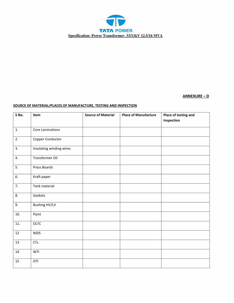
Specification- Power Transformer- 33/11kV 12.5/16 MVA
ANNEXURE – D
SOURCE OF MATERIAL/PLACES OF MANUFACTURE, TESTING AND INSPECTION
S No. Item Source of Material Place of Manufacture Place of testing and
Inspection
1. Core Laminations
2. Copper Conductor
3. Insulating winding wires
4. Transformer Oil
5. Press Boards
6. Kraft paper
7. Tank material
8. Gaskets
9. Bushing HV/LV
10. Paint
11. OLTC
12 NIDS
13 CTs
14 WTI
15 OTI

Specification- Power Transformer- 33/11kV 12.5/16 MVA

INSPECTION TEST PLAN

Initiator
HOG
(Material Quality)
Property of TPC – Not to be reproduced without permission of TPC
INSPECTION TEST PLAN FOR STAGE INSPECTION-I OF POWER TRANSFORMER
S No. Particulars Details
1 Name of firm/BA with Location
2 Order No. and Date
3 Date of stage inspection-I
4 Details of inspection offered
a) Rating
b) Quantity offered for inspection
c) Serial Numbers offered for inspection
5 Position of manufacturing for the offered quantity:
a) Tank ready
b) Core assembled
c) Coils/Winding ready for assembly
i) HV coils
ii) LV coils
6 Verification of Raw Material (approved) w.r.t consumption records.
OK/Not OK
Note: i) The stage inspection-I shall be carried out in case:-
a) 100% quantity of core and coil shall be ready for inspection. b) 100% Quantity of Tank and its mountings i.e Marshalling box, conservator etc. shall be
ready for inspection.
ii) Quantity offered for stage inspection should be offered for next level of Inspection within 15 days from the date of issuance of clearance for stage inspection, otherwise stage inspection already cleared shall be liable for cancellation.
S No. Particulars As offered
As observed Deviation and Remarks
(A) Inspection of Core : (I) Core Material
1) Manufacturer’s characteristic certificate in respect of grade of lamination used. (Please furnish test certificate)
2) Thickness of core lamination
3) Remarks regarding Rusting and smoothness of core.
(II) Core Construction :
(1) Core Diameter (mm)
(2) Total cross sectional area of core
(3) Effective cross sectional area of core
(4) Whether top yoke is cut for LV connection.
(5) If yes, at 4 above, whether Reinforcement is done.
(6) Core length (leg center to leg center)
(7) Window height.
(8) Core height
(9) Core weight only
(B) INSPECTION OF WINDING (I) Winding material
(1) Material used for
a) HV winding

Initiator
HOG
(Material Quality)
Property of TPC – Not to be reproduced without permission of TPC
b) LV winding
(2) Grade of material for
a) HV winding
b) LV winding
(3) Test certificate of manufacturer (enclosed copy) for winding material of:
a) HV
b) LV
(II) Construction Details 1) Size of Cross sectional area of conductor for :
a) HV winding
a) LV winding
2) Type of insulation for conductor of :
a) HV winding
b) LV winding
3) Diameter of coils in:
a) LV winding
a) Internal Diameter (mm)
ii) Outer diameter (mm)
b) HV winding
a) Internal diameter (mm)
ii) Outer diameter (mm)
4) Current density of winding material used for:
a) HV
b) LV
5) Total No. of turns
a) HV coils
b) LV coils
6) Total weight of coils of
a) LV winding (Kg)
b) HV winding (Kg)
(C) INSULATION MATERIALS
(I) DPC Paper Insulation
a) Type of Paper (Dotted Kraft or Diamond Dotted Kraft)
b) Make
c) Thickness (mm)
d) DPC laying direction
e) Percentage Overlapping
II) Interlayer Insulation
a) Type of Paper
b) Make
c) Thickness (mm)
III) Between HV and LV winding
a) Type of Paper
i. Make
ii. Thickness (mm) (all size)
b) Type of Pressboards
i. Make
ii. Thickness (mm) (all size)

Initiator
HOG
(Material Quality)
Property of TPC – Not to be reproduced without permission of TPC
IV) Between core and LV
Type of Paper
i. Make
ii. Thickness (mm) (all size)
Type of Pressboards
i. Make
ii. Thickness (mm) (all size)
V) Material used for top and bottom yoke and insulation
a) Type of Material
i. Make
ii.Thickness (mm) (all size)
VI) Material used for Spanner, wedge and Axial for insulation
a) Type of Material
i. Make
ii. Thickness (mm) (all size)
iii. Visual condition( i.e free from dust, burr, damage and sharp edges)
VII) Test certificate of manufacturer (enclose copy for all type of papers and pressboard used)
(D) TANK :
(I) Construction Details:
1) Shape
2) Thickness of side wall (mm)
3) Thickness of top and bottom plate (mm)
4) Provision of sloping top cover
5) Tank internal dimensions (mm)
a) Length X Width
b) Height
(II) General Details :
1) Inside painted by oil corrosion resistant paint (please specify which type of coating done)
2) Provision of lifting lugs.
a) Numbers
b) Reinforcement done by welding all side of Lug
3) Provision of air release plug
4) Provision of hot dip galvanized GI Nuts Bolts with 1no. plain and 1no. spring washer.
5) Deformation of side wall of tank when subject to:
a) Vacuum of (-) 0.7 Kg/sq.cm for 30 minutes.
b) Pressure of 0.8 Kg/sq.cm. for 30 minutes.
(E) TERMINALS:
1) Material whether of Brass Rods
a) HV
b) LV
2) Size (dia. In mm )
a) HV
b) LV
(F) BUSHINGS – Two part

Initiator
HOG
(Material Quality)
Property of TPC – Not to be reproduced without permission of TPC
1) Whether HV & LV bushings mounted as per drawing.
a) HV- Top Inclined
b) LV – Side
2) Bushing Clearance: (mm)
a) LV to Earth
b) HV to Earth
3) Bushing are two part and inner part shall be sealed and external part is replaceable without affecting sealing and need of opening of top cover.
(G) TANK BASE:
1) Whether tank base is welded folded upwards, as Specified in specification.
(H) OIL:
1) Name of supplier
2) Breakdown voltage of oil: (kV)
a) Filled in tanked transformer
b) In storage tank (to be tested by Inspecting officer).
3) Supplier’s test certificate (enclose copy)
(I) ENGRAVING:
1) Engraving of Sl. No. and name of firm and YoM.
a) On bottom of clamping channel of core-coil assembly.
b) b) On Body of tank (on Yellow base with Black paint)
(J) NAME PLATE DETAILS:
Whether Name Plate is as per approved drawing
(K) COLOUR OF TRANSFORMER
1) Tank body (Inner side) 2) Tank body (Outer side)
SOURCE OF MATERIAL/PLACES OF MANUFACTURE, TESTING
S No. Item Source of Material
Place of Manufacture
Place of testing and Inspection
1. Core Laminations
2. Copper Conductor
3. Insulating winding wires
4. Transformer Oil
5. Press Boards
6. Kraft paper
7. Tank material
8. Gaskets
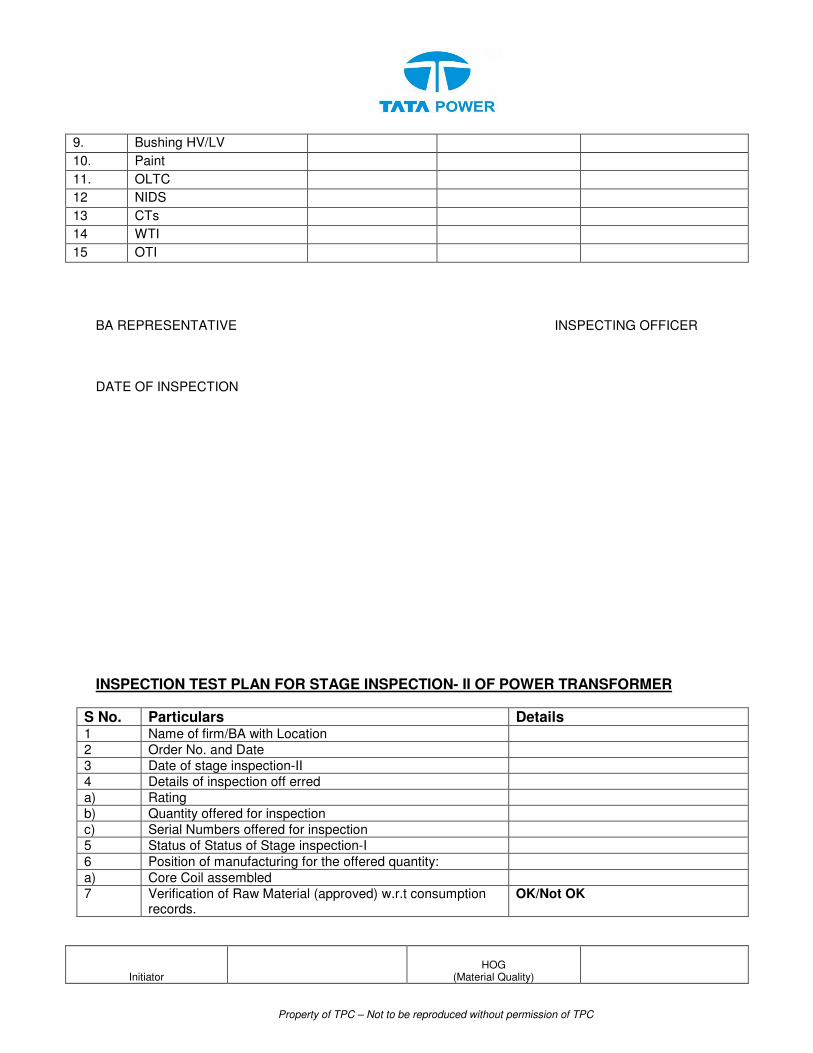
Initiator
HOG
(Material Quality)
Property of TPC – Not to be reproduced without permission of TPC
9. Bushing HV/LV
10. Paint
11. OLTC
12 NIDS
13 CTs
14 WTI
15 OTI
BA REPRESENTATIVE INSPECTING OFFICER DATE OF INSPECTION
INSPECTION TEST PLAN FOR STAGE INSPECTION- II OF POWER TRANSFORMER
S No. Particulars Details 1 Name of firm/BA with Location
2 Order No. and Date
3 Date of stage inspection-II
4 Details of inspection off erred
a) Rating
b) Quantity offered for inspection
c) Serial Numbers offered for inspection
5 Status of Status of Stage inspection-I
6 Position of manufacturing for the offered quantity:
a) Core Coil assembled
7 Verification of Raw Material (approved) w.r.t consumption records.
OK/Not OK
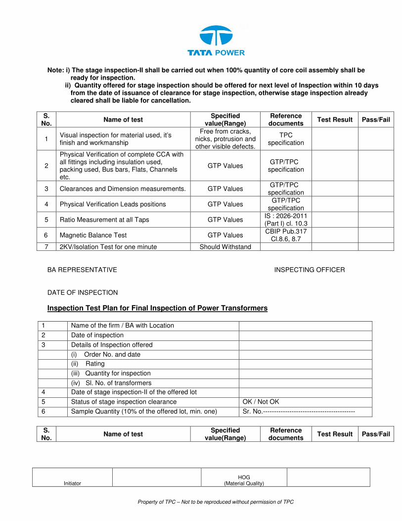
Initiator
HOG
(Material Quality)
Property of TPC – Not to be reproduced without permission of TPC
Note: i) The stage inspection-II shall be carried out when 100% quantity of core coil assembly shall be ready for inspection.
ii) Quantity offered for stage inspection should be offered for next level of Inspection within 10 days from the date of issuance of clearance for stage inspection, otherwise stage inspection already cleared shall be liable for cancellation.
S. No.
Name of test Specified
value(Range) Reference documents
Test Result Pass/Fail
1 Visual inspection for material used, it’s finish and workmanship
Free from cracks, nicks, protrusion and other visible defects.
TPC specification
2
Physical Verification of complete CCA with all fittings including insulation used, packing used, Bus bars, Flats, Channels etc.
GTP Values GTP/TPC
specification
3 Clearances and Dimension measurements. GTP Values GTP/TPC
specification
4 Physical Verification Leads positions GTP Values GTP/TPC
specification
5 Ratio Measurement at all Taps GTP Values IS : 2026-2011 (Part I) cl. 10.3
6 Magnetic Balance Test GTP Values CBIP Pub.317
Cl.8.6, 8.7
7 2KV/Isolation Test for one minute Should Withstand
BA REPRESENTATIVE INSPECTING OFFICER DATE OF INSPECTION
Inspection Test Plan for Final Inspection of Power Transformers
1 Name of the firm / BA with Location
2 Date of inspection
3 Details of Inspection offered
(i) Order No. and date
(ii) Rating
(iii) Quantity for inspection
(iv) Sl. No. of transformers
4 Date of stage inspection-II of the offered lot
5 Status of stage inspection clearance OK / Not OK
6 Sample Quantity (10% of the offered lot, min. one) Sr. No.------------------------------------------
S.
No. Name of test
Specified value(Range)
Reference documents
Test Result Pass/Fail
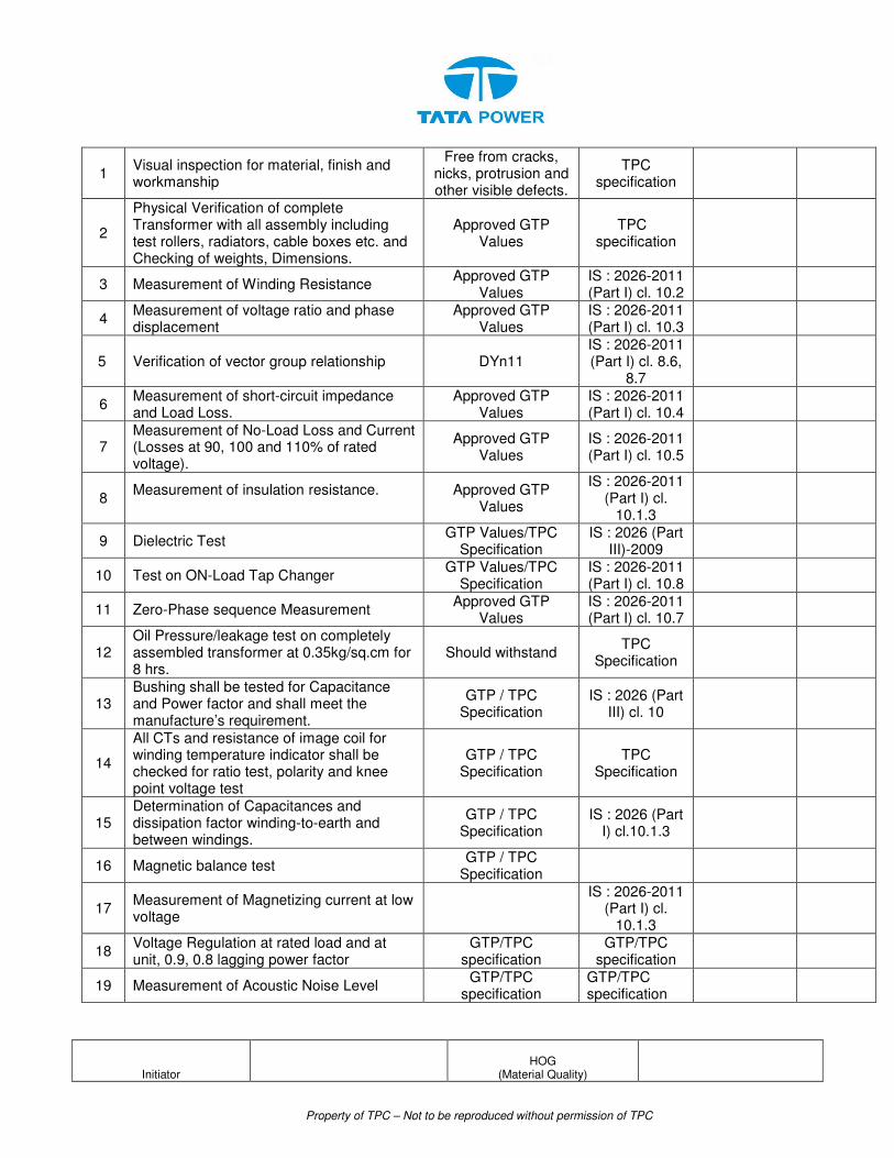
Initiator
HOG
(Material Quality)
Property of TPC – Not to be reproduced without permission of TPC
1 Visual inspection for material, finish and workmanship
Free from cracks, nicks, protrusion and other visible defects.
TPC specification
2
Physical Verification of complete Transformer with all assembly including test rollers, radiators, cable boxes etc. and Checking of weights, Dimensions.
Approved GTP Values
TPC specification
3 Measurement of Winding Resistance Approved GTP
Values IS : 2026-2011 (Part I) cl. 10.2
4 Measurement of voltage ratio and phase displacement
Approved GTP Values
IS : 2026-2011 (Part I) cl. 10.3
5 Verification of vector group relationship DYn11 IS : 2026-2011 (Part I) cl. 8.6,
8.7
6 Measurement of short-circuit impedance and Load Loss.
Approved GTP Values
IS : 2026-2011 (Part I) cl. 10.4
7 Measurement of No-Load Loss and Current (Losses at 90, 100 and 110% of rated voltage).
Approved GTP Values
IS : 2026-2011 (Part I) cl. 10.5
8 Measurement of insulation resistance.
Approved GTP Values
IS : 2026-2011 (Part I) cl.
10.1.3
9 Dielectric Test GTP Values/TPC
Specification IS : 2026 (Part
III)-2009
10 Test on ON-Load Tap Changer GTP Values/TPC
Specification IS : 2026-2011 (Part I) cl. 10.8
11 Zero-Phase sequence Measurement Approved GTP
Values IS : 2026-2011 (Part I) cl. 10.7
12 Oil Pressure/leakage test on completely assembled transformer at 0.35kg/sq.cm for 8 hrs.
Should withstand TPC
Specification
13 Bushing shall be tested for Capacitance and Power factor and shall meet the manufacture’s requirement.
GTP / TPC Specification
IS : 2026 (Part III) cl. 10
14
All CTs and resistance of image coil for winding temperature indicator shall be checked for ratio test, polarity and knee point voltage test
GTP / TPC Specification
TPC Specification
15 Determination of Capacitances and dissipation factor winding-to-earth and between windings.
GTP / TPC Specification
IS : 2026 (Part I) cl.10.1.3
16 Magnetic balance test GTP / TPC
Specification
17 Measurement of Magnetizing current at low voltage
IS : 2026-2011
(Part I) cl. 10.1.3
18 Voltage Regulation at rated load and at unit, 0.9, 0.8 lagging power factor
GTP/TPC specification
GTP/TPC specification
19 Measurement of Acoustic Noise Level GTP/TPC
specification GTP/TPC specification
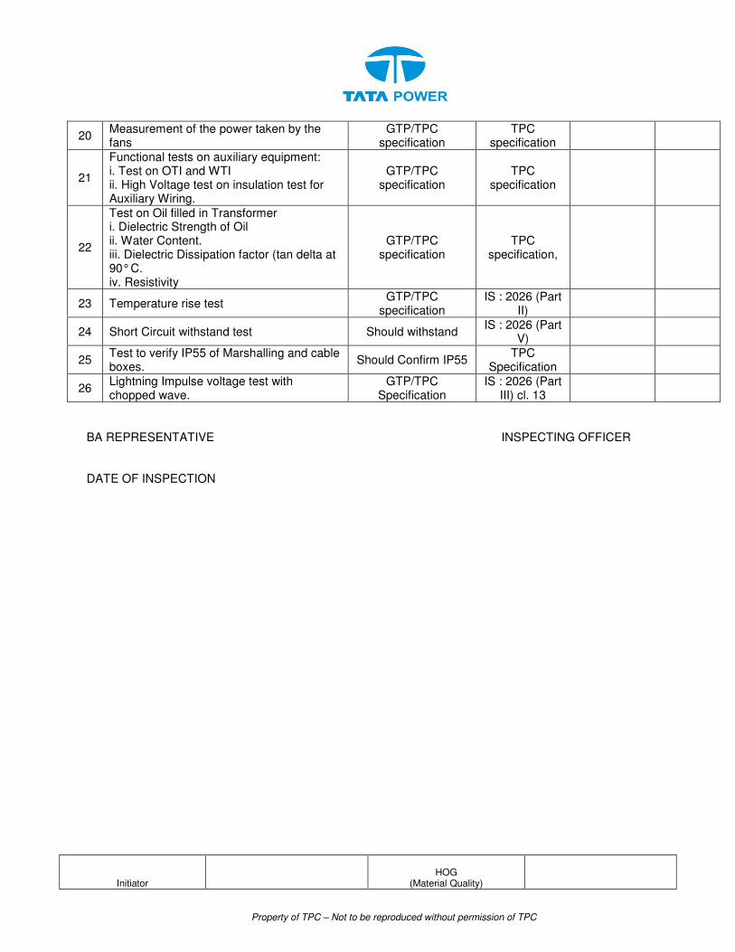
Initiator
HOG
(Material Quality)
Property of TPC – Not to be reproduced without permission of TPC
20 Measurement of the power taken by the fans
GTP/TPC specification
TPC specification
21
Functional tests on auxiliary equipment: i. Test on OTI and WTI ii. High Voltage test on insulation test for Auxiliary Wiring.
GTP/TPC specification
TPC specification
22
Test on Oil filled in Transformer i. Dielectric Strength of Oil ii. Water Content. iii. Dielectric Dissipation factor (tan delta at 90° C. iv. Resistivity
GTP/TPC specification
TPC specification,
23 Temperature rise test GTP/TPC
specification IS : 2026 (Part
II)
24 Short Circuit withstand test Should withstand IS : 2026 (Part
V)
25 Test to verify IP55 of Marshalling and cable boxes.
Should Confirm IP55 TPC
Specification
26 Lightning Impulse voltage test with chopped wave.
GTP/TPC Specification
IS : 2026 (Part III) cl. 13
BA REPRESENTATIVE INSPECTING OFFICER DATE OF INSPECTION

GENERAL CONDITIONS OF CONTRACT

THE TATA POWER COMPANY LIMITED
WORK INSTRUCTION /OPERATING GUIDELINES
Doc. Title GENERAL CONDITIONS OF CONTRACT FOR COMPOSITE WORK
Rev. No 0 Page 1 of 103
CONTENTS
CLAUSE NO. DESCRIPTION
1.0 ORGANIZATIONAL VALUES
2.0 ETHICS
3.0 CONTRACT PARAMETERS
3.1 Issue/ Award of Contract
3.2 Contract Commencement Date
3.3 Contract Completion Date
3.4 Contract Period/Time
3.5 Contract Execution Completion Date
3.6 Contract Execution Period/Time
3.7 Contract Price /Value
3.8 Contract Document
3.9 Contract Language
3.10 Reverse Auction
4.0 SCOPE OF WORK
4.1 Indemnity
4.2 Display of notice boards at work site
4.3 Disposal of waste at site
4.4 Deployment of workforce
4.5 Damage of Properties
4.6 Issuance of material
4.7 Company's right to use works
4.8 Rights of TPC to vary the scope work
5.0 PRICES/RATES/TAXES
5.1 For Supply part of Contract
5.2 For Service part of Contract
5.3 Changes in statutory Tax Structure
6.0 TERMS OF PAYMENT

Doc. Title GENERAL CONDITIONS OF CONTRACT FOR COMPOSITE WORKS
Rev. No 0 Page 2 of 103
CONTENTS
CLAUSE NO. DESCRIPTION
6.1 Pre-Requisites for Payment
6.2 Bills & Invoices
6.3 Payment & Statutory Deductions
6.4 Guidelines for Raising Running/Final Bills
6.5 Quantity Variation
6.6 Full and Final Payment
7.0 MODE OF PAYMENT
8.0 SECURITY CUM PERFORMANCE DEPOSIT
9.0 STATUTORY COMPLIANCE
9.1 Compliance to Various Acts
9.2 SA 8000
9.3 Affirmative Action
9.4 Compliance to Labour Laws
9.5 Compliance to C&D Waste Management Rules & Environment (Protection) Amendment Rules
10.0 QUALITY
10.1 Knowledge of Requirements
10.2 Material/Equipment/Works Quality
10.3 Adherence to Rules & Regulations
10.4 Specifications and Standards
11.0 SAFETY
12.0 INSPECTION/PARTICIPATION
12.1 Right to Carry Out Inspection
12.2 Facilitating Inspection
12.3 Third Party Nomination
12.4 Waiver of Inspections
12.5 Incorrect Inspection Call
13.0 MDCC & DELIVERY OF MATERIALS
13.1 Material Dispatch Clearance Certificate
13.2 Right to Rejection on Receipt

Doc. Title GENERAL CONDITIONS OF CONTRACT FOR COMPOSITE WORKS
Rev. No 0 Page 3 of 103
CONTENTS
CLAUSE NO. DESCRIPTION
13.3 Consignee
13.4 Submission of Mandatory Documents on delivery
13.5 Dispatch and Delivery Instructions
14.0 GUARANTEE
14.1 Guarantee of Performance
14.2 Guarantee period
14.3 Failure in Guarantee period (GP)
14.4 Cost of repairs on failure in GP
14.5 Guarantee Period for Goods Outsourced
14.6 Latent Defect
14.7 Support beyond the Guarantee Period
15.0 LIQUIDATED DAMAGES
15.1 LD Waiver Request
15.2 Material Recovery
16.0 ASSIGNMENT OR SUBCONTRACTING
17.0 UNLAWFUL ACTIVITIES
18.0 CONFIDENTIALITY
18.1 Documents
18.2 Geographical Data
18.3 Associate’s Processes
18.4 Exclusions
18.5 Violation
19 INTELLECTUAL PROPERTY RIGHTS
20 INDEMNITY
21 LIABILITY & LIMITATIONS
21.1 Liability
21.2 Limitation of Liability
22.0 FORCE MAJEURE
23.0 SUSPENSION OF CONTRACT

Doc. Title GENERAL CONDITIONS OF CONTRACT FOR COMPOSITE WORKS
Rev. No 0 Page 4 of 103
CONTENTS
CLAUSE NO. DESCRIPTION
23.1 Suspension for Convenience
23.2 Suspension for Breach of Contract Conditions
23.3 Compensation in lieu of Suspension
24.0 TERMINATION OF CONTRACTS
24.1 Termination for default/breach of contract
24.2 Termination for convenience of associate
24.3 Termination for Convenience of TPC
25.0 Dispute resolution and Arbitration
25.1 Governing laws and jurisdiction
26.0 ATTRIBUTES OF GCC
26.1 Cancellation
26.2 Severability
26.3 Order of Priority
27.0 INSURANCE
28.0 ERRORS AND OMISSIONS
29.0 TRANSFER OF TITLES
30.0 SUGGESTIONS & FEEDBACK
31.0 CONTACT POINTS
32.0 LIST OF ANNEXURES

Doc. Title GENERAL CONDITIONS OF CONTRACT FOR COMPOSITE WORKS
Rev. No 0 Page 5 of 103
1.0 ORGANIZATIONAL VALUES
The Tata Group has always been a value driven organization. These values continue to
direct the Group’s growth and businesses. The Six core Tata Values underpinning the way
we do business are:
Integrity - We must conduct our business fairly, with honesty and transparency. Everything
we do must stand the test of public scrutiny.
Understanding - We must be caring, respectful, compassionate and humanitarian towards
our colleagues and customers around the world and always work for the benefit of India.
Excellence - We must constantly strive to achieve the highest possible standards in our day
to day work and in the quality of goods and services we provide.
Unity - We must work cohesively with our colleagues across the group and with our
customers and partners around the world to build strong relationships based on tolerance,
understanding and mutual co-operation.
Responsibility - We must continue to be responsible and sensitive to the countries,
communities and environments in which we work, always ensuring that what comes from the
people goes back to the people many times over.
Agility - We must work in a speedy and responsive manner and be proactive and innovative
in our approach.
2.0 ETHICS
In our effort towards Excellence and in Management of Business Ethics at TPC, an Ethics
Management Team is constituted.
The main objective of the Ethics Management Team is to:
1. Record, address and allay the issues and concerns on ethics raised by different
stakeholders like employees, consumers, vendors, Associates etc. by initiating
immediate corrective actions.
2. Ensure proper communication of the ethics policies and guidelines through prominent
displays at all offices of TPC and through printed declarations in all concerned
documents where external stakeholders are involved.
3. Ensure proper framework of policies as preventive measures against any ethics
violation recorded by them.
4. Prepare and submit MIS of all issues and concerns, corrective and preventive actions
on monthly basis to the top management for their information.
All members of Team TPC, Associates and Stakeholders are requested to register any
grievance on ethics violation our website www.tatapower.com.
3.0 CONTRACT PARAMETERS
3.1 Issue/Award of Contract
TPC awards the contract to the Associate in writing in the form of Purchase order or Rate
Contract (RC) hereafter referred as Contract, through in any or all of following modes-
physical handover / post / e-mail / web document / fax with all the attachments/enclosures
which shall be part of the contract document
Doc. Title GENERAL CONDITIONS OF CONTRACT FOR COMPOSITE WORKS
Rev. No 0 Page 6 of 103
On receipt of the contract, the associate shall return to TPC copy of the contract document
duly signed by legally authorized representative of associate, within two days of Effective
Date of Contract for contracts having contract execution time less than 30 days and within
five days for all other contracts.
3.2 Contract Commencement Date
The date of issue/award of contract shall be the Effective Date of Contract or Contract
Commencement date.
3.3 Contract Completion Date
The date of expiry of Guarantee Period (detailed in section 12 of this document) shall be
deemed as the Contract Completion Date.
3.4 Contract Period/Time
The period from Contract Commencement Date to Contract Completion Date shall be
deemed as the Contract Period/Time.
3.5 Contract Execution Completion Date
The stipulated date for completing the execution of all items in the schedule of quantities
(Supply, Service and or both as applicable) shall be deemed as the Contract Execution
Completion Date.
3.6 Contract Execution Period/Time
The Period from Contract Commencement Date to Contract Execution Completion Date
shall be the Contract Execution Period/Time. Timely Completion of Works/Timely Delivery of
Materials is the essence of the contract. The period from effective date of contract to the
date stipulated for completion of delivery of all items/completion of all the works/services, as
per schedule of quantities of the contract is defined as contract execution completion time.
The Delivery of Materials /The Completion of Works, as applicable, should be achieved in all
respects as per schedules of quantities and all the terms and conditions of the contract, in
the contract execution time.
Any revision/amendment in the originally stipulated contract execution time has to be
approved by authorized representative of TPC.
3.7 Contract Price /Value
The total all inclusive price/value mentioned in the LOI/PO/RC of the contract document is
the Contract Price/Value and is based on the quantity, unit rates and prices quoted and
awarded and shall be subject to adjustment based on actual quantities supplied/actual
measurement of work done and accepted and certified by the authorized representative of
the company unless otherwise specified in schedule of quantities or in contract documents.
3.8 Contract Document
The Contract Document shall mean and include but not limited to the following:
NIT/Tender Enquiry, QR, Instruction to Bidders, Special Condition of Contract (SCC) of
tender, GCC, Technical & Commercial Specifications including relevant annexure and
attachments).
Bids & Proposals Received from Associate including relevant annexure/attachments.

Doc. Title GENERAL CONDITIONS OF CONTRACT FOR COMPOSITE WORKS
Rev. No 0 Page 7 of 103
Letter of Intent (LOI/RC/PO) with agreed deviations from the tender/bid documents.
All the Inspection and Test reports, Detailed Engineering Drawings.
Material Dispatch Clearance Certificate (MDCC).
Minutes of Meeting (MoM)
3.9 Contract Language
All documents, instructions, catalogues, brochures, pamphlets, design data, norms and
calculations, drawings, operation, maintenance and safety manuals, reports, labels, on
deliveries and any other data shall be in English Language.
The Contract documents and all correspondence between the TPC, Third Parties associated
with the contract, and the Associate shall be in English language.
However, all signboards required indicating "Danger" and/or security at site and otherwise
statutory required shall be in English, Hindi, and local languages.
3.10 Reverse Auction
TPC reserves the right to conduct the reverse auction (instead of public opening of price
bids) for the products / services being asked for in the tender. The terms and conditions for
such reverse auction events shall be as per the Acceptance Form attached in Annexure J.
The bidders along with the tender document shall mandatorily submit a duly signed copy of
the Acceptance Form as mentioned in the Annexure J as a token of acceptance for the
same.
4.0 SCOPE OF WORK
All the activities that are to be undertaken by the Associate to realize the contractual
deliverables in completeness form Scope of Work. Following clauses list, but not limited to,
major requirements of the scope of work.
The associate shall satisfy himself and undertake fully the technical/commercial
requirements of items to be supplied as listed in the Schedule of Quantities together with the
tests to be performed /test reports to be furnished before dispatch, arrangement of stage and
final inspections during manufacturing as per terms and conditions of contract, technical
parameters & delivery terms and conditions including transit insurance to be met in order to
fully meet TPC’s requirements.
Completeness: Any supplies and services which might have not been specifically mentioned
in the Contract but are necessary for the scope mentioned in Special Terms & Conditions
and/or completeness of the works at the highest possible level, including any royalties,
licence fees & compensation to be paid, whether incurred by the associates or by a third
party for the work covered in the scope, regardless of when incurred, shall be
supplied/provided by the associate without any extra cost and within the time schedule for
efficient , smooth and satisfactory operation and maintenance of the works at the highest
possible level under Indian conditions (but according to international standards for facility of
this type), unless expressly excluded from the scope of supplies and services in this
Contract.
TPC have the right, during the performance of the Contract, to change the scope and/or
technical character of the Project and/or of the supplies and services stipulated in the

Doc. Title GENERAL CONDITIONS OF CONTRACT FOR COMPOSITE WORKS
Rev. No 0 Page 8 of 103
Contract by submitting a request in writing to the Associate. The Associate shall, within
fifteen days of receipt of such request from the TPC, provide Purchaser with a reasonably
detailed estimate of the cost of the change outlined in the request.
In the event, TPC requests a change, the Contract price and time shall be adjusted upwards
or downwards, as the case may be and shall be mutually agreed to. The associate shall not
be entitled to any extension of time unless such changes adversely affect the time schedule.
The Associate shall not proceed with the changes as requested till adjustment of contract
price and time schedule where so applicable in terms of or otherwise directed by the TPC.
4.1 Indemnity
Associates shall undertake to fully indemnify TPC (also referred to as the Company in the
GCC) against all kinds of liabilities or damages, of whatsoever nature, including
compensation arising from any accident to the person or property of those in Associate’s
employment or to any other person or properties including those of TPC, arising due to
reasons attributable to any, act, omission or negligence of the Associate the Associates, for
the entire period of contract including period of guarantee.
Within 7 days of award of work, the Associates shall submit Indemnity Bond in the format as
per Annexure-E to Order Issuing Authority.
Contract having value more than Rs 2 Cr per Annum, Associates shall submit Indemnity
Bond on Rs 100/- Non Judicial Stamp Paper in the format as per Annexure- E to Order
Issuing Authority.
4.2 Display of Notice Boards at Work Sites
The Associate shall put up display notice board at each project site where the works are in
progress indicating the information given below:
Name of the Project.
Estimated Cost of Project.
Date of Commencement.
Expected date of completion.
Name of Associate and his telephone number.
Name of Engineer-in-Charge and his telephone number.
4.3 Disposal of Waste at Site
Significant quantities of waste are generated during the execution of project and an
integrated approach for effective handling, storage, transportation and disposal of the same
shall be adopted. This would ensure the minimization of environmental and social impact in
order to combat the climate change.
The associates shall follow the below criteria for disposal of waste at site during the
execution of project.
Associate shall ensure that the detailed project plan include the waste management,
segregation of all designated waste material (Recyclable/ Non-Recyclable), collecting,
storing, disposing and transferring the same to pre-arranged facility/destination in timely
and safe manner as per environmental legislations during the execution of project. The
project plan shall also include the innovative construction practice to eliminate or
minimize waste, protect surface/ground water, control dust and other emissions to air
Doc. Title GENERAL CONDITIONS OF CONTRACT FOR COMPOSITE WORKS
Rev. No 0 Page 9 of 103
and control noise during the execution of project. The copy of same shall be given to
EIC before the commencement of project.
The purchase policy of BA shall encourage the procurement of material with recycled
and minimum packaging of goods during delivery. Associate shall provide the
appropriate means for site to site transportation of materials to avoid damage and litter
generation.
Associate shall educate and inform to its project team about the requirement and
responsibilities for waste minimization and disposal in general and provide training of
practices that support this. Waste management should be treated like a safety program.
In the event that area of contaminated or biological hazard is identified, Associate shall
ensure that plant, equipment, personnel and any activity associated with the work is
carried out in consultation with EIC of TPC.
Associate shall ensure that the residents living near the site are kept informed about
proposed working schedule and shall informed timings and duration of any abnormal
noise full activity that is likely to happen.
Associate shall ensure the regular maintenance and monitoring of vehicles and
equipment for efficient fuel use so that emissions and noise are within acceptable limits
to avoid air pollution.
4.4 Deployment of Work Force
Associate shall deploy adequate labour, as considered necessary by TPC for execution of
the contract including Sundays and Holidays whenever required to do so with no extra cost
to TPC. However, prior permission shall be taken from the site Engineer to carry out the
work beyond normal working hours or on Sundays and Holidays. Female employees shall
not be deployed beyond normal working hours/days and no child labour shall ever be
deployed. Associate shall depute full time qualified and experienced engineers to supervise
the work at site. All such staff shall be maintained from commencement to completion of all
works to the entire satisfaction of the Engineer-in-Charge. Associate’s employees deployed
for the works under this contract will not be considered in Company’s employment at any
time. Associate shall continue to be responsible for all such employees, their safety, all types
of statutory compliances related thereto and in any other manner whatsoever. The company
will stand indemnified by the Associate in respect of all the above. At the same time
Company upon noticing any breach or default on any statutory compliances, may at their
sole discretion, decide to act in a manner as deemed fit at the risks and costs of the
Associate.
TPC shall have the right to instruct the Associate to change the Sub- Associates or skilled
/unskilled workers in case the conduct, the workmanship or speed of the work is not
satisfactory.
Associates shall submit duly signed undertaking regarding engagement of competent staff /
employee commensurate to the nature of job to Engineer–in–charge in the format attached
as Annexure – H.
4.5 Damages to Properties
The Associates shall take necessary steps to ensure that the equipment and installations of
the Company, Third parties, including other utility services like water supply pipelines; open

Doc. Title GENERAL CONDITIONS OF CONTRACT FOR COMPOSITE WORKS
Rev. No 0 Page 10 of 103
drains telephone cables etc. are not damaged during execution of the works. The Associates
shall be responsible for all such damages and shall have to repair/ replace and/or
compensate for the entire claims in respect of such damages at its own cost.
4.6 Issuance of Material
The material issued to the Associate shall be in the custody of the Associates who shall be
fully responsible for the same. After completion of the works, the Associates will reconcile
the material. Any cost of material which is short or damaged/lost will be deducted from
Associate bill/ deposits.
4.7 Company’s Right To Use Works
If Taking Over Certificate is delayed for any reason, for which TPC’s decision shall be final
and binding upon the Associate, the Company shall be entitled to use the works or portion
thereof without affecting Associate’s responsibility and liability to complete the balance works
as per company’s directives from time to time, though Associate shall be afforded
reasonable opportunity by the company to enable Associates to complete all balance works
required for issuance of ‘Taking Over Certificate’ by the company.
4.8 Rights of TPC to vary the scope work
TPC shall have the right, during the performance of the Contract, to change the scope
and/or technical character of the Project and/or of the supplies and services stipulated in the
Contract by communicating the intent to do so in writing to the Associate. On receipt of such
communication the Associate shall, within the time frame specified in the contract shall
provide TPC with a reasonably detailed estimate of the cost of the change in scope outlined
in the TPC communication. The change in the Contract price and time shall be revised
upwards or downwards, as the case may be, and shall be mutually agreed to. The Associate
shall not be entitled to any extension of time unless such changes adversely affect the time
schedule.
The Associate shall not proceed with the changes in the scope of work till such time revision
of Contract price and time schedule are approved and communicated to the associate by
TPC.
Any change in the Scope of Work and/or Terms & Conditions of the order shall be intimated
by TPC through an amendment to the contract. The amendment shall be treated valid only if
signed by the authorized signatory of the original contract.
5.0 PRICES/ RATES/ TAXES
5.1 For Supply part of Contract
Unless specified elsewhere in the contract document, the prices/rates are inclusive of cost of
finished product for which MDCC will be issued by TPC, packaging and forwarding charges,
freight and transit insurance charges covering loading at Associate’s works, transportation to
TPC store/site & unloading & delivery at TPC stores/TPC site, cost of documentation
including all the relevant test certificates and other supportive documents to be furnished.
The Prices/Rates are inclusive of all taxes, levies, cesses and duties, particularly Goods and
Services Tax as applicable. All government levy / taxes shall be paid only when the invoice
is submitted according to the relevant act.

Doc. Title GENERAL CONDITIONS OF CONTRACT FOR COMPOSITE WORKS
Rev. No 0 Page 11 of 103
The prices/rates shall remain firm till actual completion of entire supply of
goods/material/equipment as per contract is achieved and shall remain valid till the
completion of the contract.
The prices shall remain unchanged irrespective of TPC making changes in quantum in all or
any of the schedules of items of contract.
5.2 For Service part of Contract
The Prices and Rates are inclusive of cost of materials supplied as per contract terms and
for which MDCC is issued by TPC and to the extent required for completion of works, cost of
service executed as per schedule of quantities, cost of testing as per contract terms, cost of
documentations including all relevant test certificates and other supportive documents to be
furnished as per contract terms. The rates shall remain firm till actual completion of contract.
The Prices/Rates are inclusive of all taxes, levies, cesses and duties, particularly Goods and
Services Tax as applicable. All government levy / taxes shall be paid only when the invoice
is submitted according to the relevant act.
The prices shall remain unchanged irrespective of TPC making changes in quantum in all or
any of the schedules of items of contract.
5.3 Changes in Statutory Tax Structure
If rate of any or all of the statutory taxes and duties applicable to the contract changes, such
changes shall be incorporated by default if the changes occur within the contract execution
time and shall be applicable if the contract is executed by the Associate within the Contract
Execution Time.
For execution of contracts beyond contract execution time, where the delay is not
attributable to TPC no upward revision in tax /duties shall be considered irrespective of
changes in the statutory tax structure either within the contract execution time or beyond.
However, in such cases, benefits due to any downward revisions in statutory tax rates shall
be passed on to TPC.
6.0 TERMS OF PAYMENT
A. 5% of the Release Order/ Purchase Order price shall be paid as initial interest free
advance on fulfillment of the following by the Associate:
a) Acceptance of PO/ LOI.
b) Submission of advance payment BG of 15% of the Release Order/ Purchase
Order price which shall remain valid till the advance is fully adjusted.
c) Submission of Contract Performance Bank Guarantee of 5/10% of the RC/
PO price valid till 30 days after taking over of the works.
B. 10% of the Release Order/ Purchase Order price shall be paid as interest free
advance against approval of drawings under Category-1 of major drawings, Quality
Plans, Pert Chart, Field Quality Plan, posting of Project Manager
and commencement of the first mile stone of the work mutually agreed including C-3
Form, and submission of a true copy of ‘Erection All Risk Insurance Policy’ taken for
the awarded jobs. The drawing list shall be mutually agreed at the time of award of
work.

Doc. Title GENERAL CONDITIONS OF CONTRACT FOR COMPOSITE WORKS
Rev. No 0 Page 12 of 103
C. 50% on account payment of the total of item wise cost of material Release Order/
Purchase Order shall be paid against receipt of material at site in good condition and
certification by TPC along with bills complete in all respects viz. MDCCs etc.
D. 20% on account payment of the actual executed value shall be paid against
mechanical completion of erection on prorate basis against monthly bills and 70% on
account of the actual executed value shall be paid against the service line item
including composite line item. In case this milestone is not completed beyond 120
days for reasons attributable to TPC, the payment corresponding to supply part shall
be released subject to submission of BG of equivalent amount by the BA valid for a
period of further 12 months. If required, it shall be extended by the BA on request of
TPC.
E. 15% payment of the actual executed Release Order/ Purchase Order shall be paid
after completion of acceptance test and Taking Over of the complete systems
specified in the enquiry, including clearance of Electrical Inspection, compliance of
final punch point and after reconciliation & adjustment of payments, if any, towards
Quantities of materials issued from purchaser’s stock and consumed by the
contractor for expeditious completion of the job. In case this milestone is not
completed beyond 120 days beyond schedule for reasons attributable to TPC, the
payment corresponding to supply part shall be released subject to submission of BG
of equivalent amount by the BA valid for a period of further 12 months. If required, it
shall be extended by the BA on request of TPC.
The Contractor shall submit all Operation & Maintenance manuals and “As Built
Drawings” etc. and shall also submit Equipment Warranty Bank Guarantee (EWBG)
equivalent to 5/10% of actual executed contract price before the release of this last
payment and return of CPBG. The validity of EWBG shall be for a period of 15
months from the date of taking over of the works or specified guarantee period in
drawing/tender/technical specification documents etc. whichever is later. The
associate shall also submit ‘No Demand Certificate’ at the time of receipt of full and
final payment.
6.1 Pre-Requisites for Payment
Associate should have completed execution of that part of contract, for which payment is
sought, to the satisfaction of TPC’s Engineer-in-Charge responsible for the contract and
obtained certification for execution of the work.
Associate has undertaken joint measurement of the work executed along with TPC’s
Engineer-in-charge
Associate’s bills/invoices submitted have been certified by Engineer-In-Charge.
6.2 Bills & Invoices
Unless specified otherwise in the special conditions of contract, Associate shall raise not
more than one invoice/contract per month for the services rendered in the prescribed Tax
Format and the invoice shall be submitted within 15 days of the following month at TPC.
All Bills shall be supported by joint measurement of work done, quality test report and a copy
of wage sheet, if applicable (showing proof of having disbursed wages as per applicable law)
and a copy of statement substantiating that statutory payments having been affected.

Doc. Title GENERAL CONDITIONS OF CONTRACT FOR COMPOSITE WORKS
Rev. No 0 Page 13 of 103
Bills/ invoices shall mention Associate’s GST Number, PAN number as applicable.
Final bill submission after completion of project or execution of job must be within 30 days
from the actual date of completion/execution of work awarded.
6.3 Payment & Statutory Deductions
Payment shall be released within 30 days from the submission of the bills. The associate
shall submit “No Demand Certificate” in the format as per Annexure-D at the time of receipt
of full and final payment. In case any non-compliance to contract conditions comes to TPC’s
notice, TPC will be entitled to deduct 30% of estimated wages plus 20% of wages as TPC’s
overheads. Associates would be obliged to provide the copy of monthly wage sheet in any
case, failing which no payment shall be made. TPC at their sole discretion may deposit the
PF etc. with statutory authorities. TPC will deduct the amounts of TDS as per statutory
requirement under the income tax act and the DVAT Act and certificates (wherever
applicable) will be issued to associate accordingly.
In case of non-submission of PAN No TDS @ 20% shall be deducted from all payable
amounts for which no TDS certificate shall be issued. TDS once deducted as above shall not
be revised in any condition.
6.3.1 Statutory Deductions
TPC will deduct the amounts of TDS, TCS as per statutory requirement under the income tax
act, the Goods and Services tax act, BOCW Act, or any other applicable tax act and
certificates (wherever applicable) will be issued to associate accordingly. For consumption of
TPC’s Water and Electricity by Associate for execution of Contract, Associate shall pay 0.5%
& 1.0% respectively of contract value and it shall be deducted from the running bills. The
Engineer-in-Charge as stated in the Order shall be responsible for certification of the work
executed and the bills. Bills (including original) shall be submitted in triplicate at Bill Inward
Receipt Desk (BIRD) located at Civil lines-III, Near Vidhan Sabha, TPC.
6.4 Guidelines for Raising Running/Final Bills
Contract Value Up to 5 Lakhs One Final Bill
Contract Value More than 5 lakhs Monthly Running Bill & One Final Bill
All Bills shall be processed only when all bank Guarantees are in place and before payments
of Final Bill Associate have to furnish NDC.
6.5 Quantity Variation
Payment will be made on the basis of actual quantity of supplies/actual measurement of
works accepted by TPC and not on the basis of contract quantity.
6.6 Full and Final Payment
Full & Final Payment in all contracts shall be made subject to the associate submitting “No
Demand Certificate” in the format as per Annexure-D.
7.0 MODE OF PAYMENT
Payment shall be made through RTGS mode for which Business Associated shall submit the
details of Bank Account and other details as per annexure K. Further, for any payments
made, TPC is not responsible for any consequences/disputes Associate have among the

Doc. Title GENERAL CONDITIONS OF CONTRACT FOR COMPOSITE WORKS
Rev. No 0 Page 14 of 103
owners channel partners, sub-Associates and all such dispute/concerns shall be settled
solely by the Associate.
The quantities of items indicated are estimated and preliminary. However, payments shall be
made on the basis of actual quantity of work carried out and measured jointly by the
Company and the Associate. Associates shall be responsible to organize joint
measurements of works with TPC Engineer-in-Charge before raising any bill of work done.
In the event Associate fails to do so, TPC at their sole discretion, may take measurements of
work done and proceed as deemed fit and in such an event Associate’s right to lodge any
subsequent claim shall stand forfeited.
8.0 SECURITY CUM PERFORMANCE DEPOSIT
Associates shall submit within 15 days from the effective date of issue of PO/RC, Security
cum Performance Guarantee (SPBG) in the format as per Annexure B of this document from
banks acceptable to TPC for:
(a) 5% of the PO value if purchase order value is more than Rs 5 Crores.
(b) 10% of the PO value if purchase order value is less than Rs 5 Crores.
This shall remain valid till the end of the Guarantee Period of contract, plus one month.
(c) 5% of the RC value in case of Rate Contract. This shall remain valid till the Guarantee
period plus one month.
For PO/RC values less than Rs. 5 lacs, Associate may request for deduction of amount
equivalent to SPBG value from their first invoice. Such amount shall be withheld by TPC
while processing the invoice and shall be released after completion of Guarantee Period
plus one month.
For PO/RC values less than Rs. 3 lacs, the clause (8.0) for Security cum Performance
Bank Guarantee (SPBG) shall not be applicable.
In case of RC (Rate Contract) after the expiry of RC validity, Associate shall have to
submit SPBG. However, the Associate has the option to re-submit the SPBG as per
actual RO (Release Order) value issued against the RC, valid for Guarantee Period plus
one month. The Guarantee Period shall be considered as per the last RO issued against
the said RC. The original SPBG as submitted against the RC shall be released on
submission of the new SPBG to TPC. Alternatively, Associate may extend the validity of
original SPBG only till the requisite period, i.e. Guarantee Period plus one month.
9.0 STATUTORY COMPLIANCE
9.1 Compliance to Various Acts
Associate should ensure adherence to all applicable laws, rules and regulation applicable
under this contract from time to time. In case of violation any risk, costs etc shall be in
associates account and keep TPC indemnified always till completion of contracts.
9.2 SA 8000
Further being TPC is SA 8000 complied and expects its Associates to follow guidelines of
SA8000: 2014 on the following aspects
1. Child Labour
2. Forced or Compulsory Labour
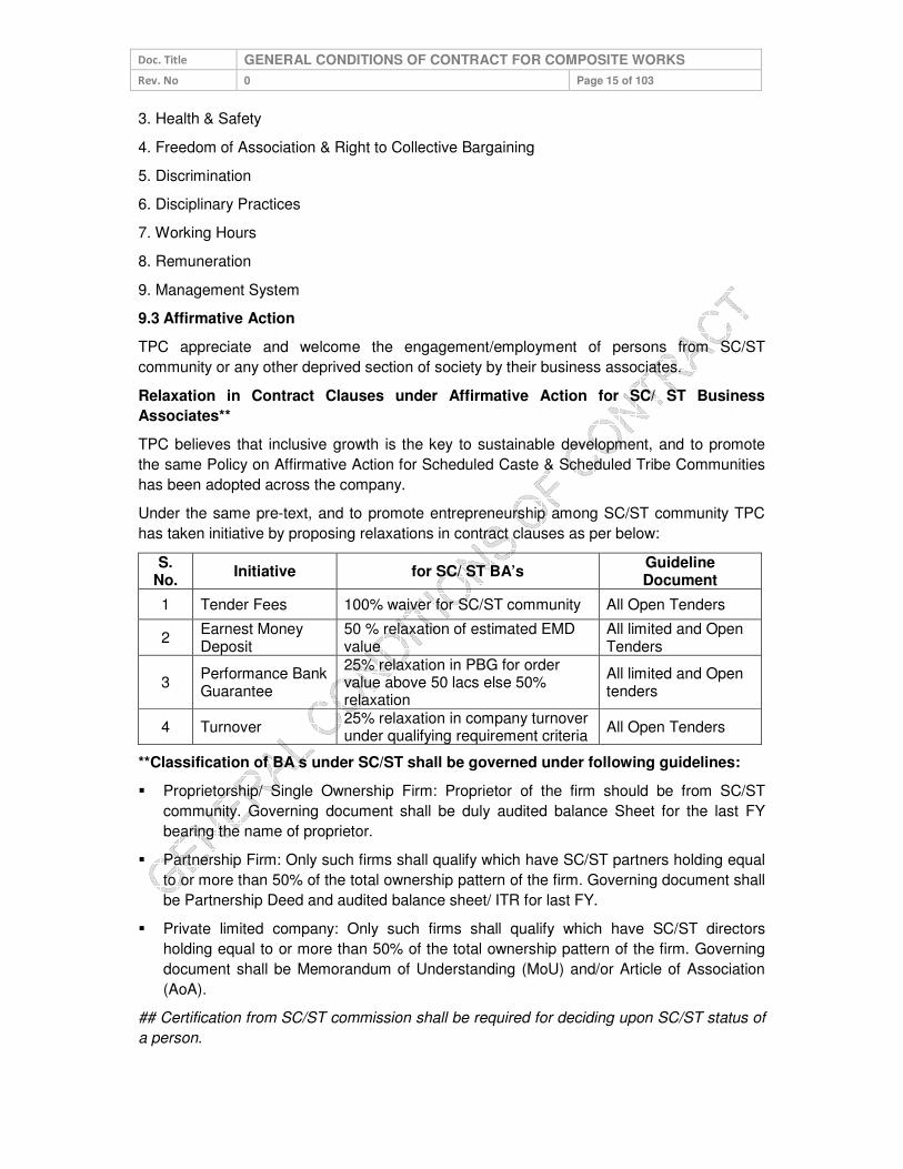
Doc. Title GENERAL CONDITIONS OF CONTRACT FOR COMPOSITE WORKS
Rev. No 0 Page 15 of 103
3. Health & Safety
4. Freedom of Association & Right to Collective Bargaining
5. Discrimination
6. Disciplinary Practices
7. Working Hours
8. Remuneration
9. Management System
9.3 Affirmative Action
TPC appreciate and welcome the engagement/employment of persons from SC/ST
community or any other deprived section of society by their business associates.
Relaxation in Contract Clauses under Affirmative Action for SC/ ST Business
Associates**
TPC believes that inclusive growth is the key to sustainable development, and to promote
the same Policy on Affirmative Action for Scheduled Caste & Scheduled Tribe Communities
has been adopted across the company.
Under the same pre-text, and to promote entrepreneurship among SC/ST community TPC
has taken initiative by proposing relaxations in contract clauses as per below:
S. No.
Initiative for SC/ ST BA’s Guideline Document
1 Tender Fees 100% waiver for SC/ST community All Open Tenders
2 Earnest Money Deposit
50 % relaxation of estimated EMD value
All limited and Open Tenders
3 Performance Bank Guarantee
25% relaxation in PBG for order value above 50 lacs else 50% relaxation
All limited and Open tenders
4 Turnover 25% relaxation in company turnover under qualifying requirement criteria
All Open Tenders
**Classification of BA s under SC/ST shall be governed under following guidelines:
Proprietorship/ Single Ownership Firm: Proprietor of the firm should be from SC/ST
community. Governing document shall be duly audited balance Sheet for the last FY
bearing the name of proprietor.
Partnership Firm: Only such firms shall qualify which have SC/ST partners holding equal
to or more than 50% of the total ownership pattern of the firm. Governing document shall
be Partnership Deed and audited balance sheet/ ITR for last FY.
Private limited company: Only such firms shall qualify which have SC/ST directors
holding equal to or more than 50% of the total ownership pattern of the firm. Governing
document shall be Memorandum of Understanding (MoU) and/or Article of Association
(AoA).
## Certification from SC/ST commission shall be required for deciding upon SC/ST status of
a person.

Doc. Title GENERAL CONDITIONS OF CONTRACT FOR COMPOSITE WORKS
Rev. No 0 Page 16 of 103
9.4 Compliance to Labor Laws
Bidder needs to ensure compliance to applicable labor laws including timely disbursement of
wages. In case wages are not disbursed as per the stipulated timelines, then TPC shall pay
the wages to BA employees on behalf of BA. Apart from deducting the amount of wages
paid, TPC shall deduct an additional service charge equivalent to 25% of the wages paid
from the payment due to BA.
9.5 Compliance to Construction and Demolition Waste Management Rules &
Environment (Protection) Amendment Rules
BA is liable to follow the Construction and Demolition Waste Management Rules- 2016,
Environment (Protection) Amendment Rules- 2018 and Guidelines on dust mitigation
measures in handling construction material and C&D wastes issued by CPCB.
Following are some main points of above Rules/Guidelines for Construction work, cable
laying jobs etc.
1. Barricading to be provided at site to cover complete area. 2. Construction material and waste should be inside the closed area made by using
barricading. 3. Water sprinkling/fine spray from nozzles to be done to suppress the dust. 4. The board of Dust mitigation measures shall be displayed at site for public viewing
with required details. 5. Loose sand or soil and construction material that causes dust shall be covered. 6. Transport material that are easily wind borne need to be covered by a sheet made of
either jute, tarpaulin, plastic or any other effective material. 7. All areas for storing C&D waste/construction material to be demarcated and
preferably barricaded particularly those materials that have potential to be dust borne.
8. Grinding and cutting of building materials in open area shall be prohibited. 9. Construction material and waste should be stored only within earmarked area and
road side storage of construction material and waste shall be prohibited. 10. No uncovered vehicles carrying construction material and waste shall be permitted. 11. Construction and demolition waste processing and disposal site shall be identified
and required dust mitigation measures to be notified at the site.
10.0 QUALITY
10.1 Knowledge of Requirements
The Associate shall be deemed to have carefully examined and to have knowledge of the
equipment, the general and other conditions, specifications, schedules, drawings, etc.
forming part of the Contract and also to have satisfied himself as to the nature and character
of the work to be executed and the type of the equipment and duties required including
wherever necessary of the site conditions and relevant matters and details. Any information
thus procured or otherwise obtained from TPC/Consultants shall not in any way relieve the
Associate from his responsibility and executing the works in accordance with the terms of
contract.
10.2 Material/Equipment/Works Quality
The items / works under the scope of the Associate shall be of the best quality and
workmanship according to the latest engineering practice and shall be manufactured from

Doc. Title GENERAL CONDITIONS OF CONTRACT FOR COMPOSITE WORKS
Rev. No 0 Page 17 of 103
materials of best quality considering strength and durability for their best performance and, in
any case, in accordance with the specifications set forth in this Contract. All material shall be
new. Substitution of specified material or variation from the process of
fabrication/construction/manufacture may be permitted but only with the prior written
approval of the TPC.
10.3 Adherence to Rules & Regulations
The Associate shall procure and/or fabricate/erect all materials and equipment in
accordance with all requirements of Central and State enactment, rules and regulations
governing such work in India and at site. This shall not be construed as relieving the
Associate from complying with any requirement of TPC as enumerated in the Contract which
may be more rigid than and not contrary to the above mentioned rules, nor providing such
construction as may be required by the above mentioned rules and regulations. In case of
variance of the Technical Specification from the laws, ordinance, rules and regulations
governing the work, the Associate shall immediately notify the same to the TPC. It is the sole
responsibility of the Associate, however, to determine that such variance exists. Wherever
required by rules and regulations, the Associate shall also obtain the statutory authorities'
approval for the plant, machinery and equipment to be supplied by the Associate.
10.4 Specifications and Standards
The Associate shall follow all codes and standards referred in the Contract Document.
Codes and standards of other may be followed by the Associate with the prior written
approval of TPC, provided materials, supplies and equipment according to the standard are
equal to or better than the corresponding standards specified in the Contract.
Brand names mentioned in the Contract documents are for the purpose of establishing the
type and quality of products to be used. The Associate shall not change the brand name
and qualities of the bought out items without the prior written approval of the TPC. All such
products and equipment shall be used or installed in strict accordance with original
manufacturer's recommendations, unless otherwise directed by the TPC. In any
circumstances the codes, specimen and standards prescribed by any government agency
should not be violated.
11.0 SAFETY
All Associates shall strictly abide by the guidelines provided in TPC’s Contractor Safety
Management System (CSMS) as applicable at all stages during the contract period.
Associate shall execute the contracts ensuring the following in and as order of priority:
Safety of Human Beings.
Safety of equipment/Assets.
Timely Completion of Contract.
Safety related requirements as mentioned in our Contractor Safety Management System is
attached as annexure L and is an integral part of this GCC.
12.0 INSPECTION/PARTICIPATION
12.1 Right to Carry Out Inspection
TPC reserves the right to send its representatives for inspection or participation at various
stages of contract execution listed below, applicable as per contract construction.

Doc. Title GENERAL CONDITIONS OF CONTRACT FOR COMPOSITE WORKS
Rev. No 0 Page 18 of 103
During basic design and detail engineering of material/ Equipment carried out by
Associate /Outsourced Agencies.
During manufacturing stages of the product at Associate’s/Associate’s Outsourced
Agency’s Plant/Facility.
During Pre-dispatch Inspection and Testing of finished/manufactured product at
Associate’s/Associate’s outsourced Agency’s Plant/Facility.
During Installation & Commissioning Activities/Stages.
Prior to Clearing of the completed installation for commissioning.
Any other stage as find appropriate by TPC during contract execution time.
All inspections and participations shall be carried out within maximum of two weeks of TPC
giving written intimation to the Associate or receiving appropriate advance written inspection
call from the Associate, unless otherwise specified elsewhere in the contract document.
12.2 Facilitating Inspection
The Associate shall provide all opportunities and information to TPC’s engineers to get
acquainted with the technical know-how and the methods and practices adopted by the
Associate in basic and detail engineering. The Associate shall provide documents, drawings,
calculations etc. as may be required by TPC’s Engineers.
The Associate shall provide free of charge office accommodation, office facilities, secretarial
services, communication facilities, general and drawing office stationary, etc. as may be
reasonably required by the TPC’s engineers. Similarly, facilities shall also be provided by
Associate's outsource agencies/partners/authorized dealers (collectively termed as sub-
associates) if such basic and detail engineering activities are carried out in the design offices
of sub-Associates.
The Associate shall be responsible for the safety of employees of TPC/Third Party Agency
when they are at the Associate’s /Associate’s outsource agency’s plant or facility for carrying
out/witnessing inspection/testing. All statutory safety precautions as applicable shall be
followed by the Associate during Inspection Testing. If TPC inspectors are not satisfied with
the safety arrangements at the plant, TPC have the right to call off inspection till such time
corrective action is taken by the Associate.
Before raising the call for pre-dispatch final inspection and testing, the Associate shall
conduct all the tests—type tests, routine tests etc-as specified in the contract document and
submit copies of the test certificates to TPC along with the inspection call, for scrutiny of
TPC.
The Associate and TPC shall jointly document all the observations, comments and action
points after completion of inspection and it shall be binding on the Associate to provide
compliance on all the points requiring compliance and furnish the compliance report to the
designated authority of TPC for receiving clearance for dispatch of materials.
12.3 Third Party Nomination
TPC also may nominate a third party for the purpose of carrying out the inspection and such
an agency shall be entitled to all the rights and privileges of TPC as far as conducting the
inspection.

Doc. Title GENERAL CONDITIONS OF CONTRACT FOR COMPOSITE WORKS
Rev. No 0 Page 19 of 103
12.4 Waiver of Inspections
TPC on its own discretion shall chose to waive off any inspection and ask the Associate to
submit all the test reports as applicable as per contract specifications, related to inspection
and testing of the goods ordered for scrutiny and clearance for dispatch.
12.5 Incorrect Inspection Call
In case it is observed that the material offered for inspection is not ready at the time of TPC inspection visit rendering it as futile, all costs towards such inspection shall be recovered from the BA. Taxes as applicable on such recoveries shall be borne by the BA.
13.0 MDCC & DELIVERY OF MATERIALS
13.1 Material Dispatch Clearance Certificate
Associate shall deliver material/goods/equipment against Supply Contracts or Supply Part of
Composite/Service Contracts only after receiving Material Dispatch Clearance Certificate
(hereafter termed as MDCC) issued by designated authority of TPC. Material delivered at
TPC stores or at project site without a valid MDCC issued by the designated official of TPC
shall be rejected. MDCC shall be issued to associate furnishing compliance report on the
action points documented during pre-dispatch inspection and testing at Associate’s/ Sub-
Associate’s plant/ facility. In case Pre-dispatch inspection is waived at the discretion of TPC,
then, MDCC shall be issued on receiving all the test reports-routine& type-from the
Associate and finding them in order.
The associate shall include and provide for securely protecting and packing the materials so
as to avoid loss or damage during handling and transport by air, sea, rail and road or any
other means.
All such packing shall allow to the extent possible for easy removal and checking at Site.
The associate shall take special precautions to prevent rusting of steel and iron parts during
transit by sea. Gas seals or other materials shall be utilised by the associate for protection
against moisture during transit of all Plant and Equipment.
Each Equipment or parts of Equipment shall be tagged with reference to the assembly
drawings and corresponding part numbers. Each bale or package shall contain a packing
note quoting specifically the name of the associate, item description, quantity, item / package
identification.
All packing cases, containers, packing and other similar materials shall be new and supplied
free by the associate and it shall not be required to be returned to the associate.
Notwithstanding anything stated in this clause, the associate shall be entirely responsible for
loss, damage or depreciation or deterioration to the materials and supplies due to faulty
and/or insecure packing or otherwise during transportation to the Site until otherwise
provided herein.
In case of the consignments dispatched by road, the associate shall ensure that it or its sub-
contractors:
i) Identify and obtain the correct type of trucks/trailers, keeping in view the nature of
consignments to be dispatched.

Doc. Title GENERAL CONDITIONS OF CONTRACT FOR COMPOSITE WORKS
Rev. No 0 Page 20 of 103
ii) Take such actions as may be necessary to avoid all possible chances of damages during
transit and to ensure that all packages are firmly secured.
Timelines for inspection and MDCC is as below:
S. No.
Inspection MDCC issuance time including
inspection time (max.)
1 Outside Bhubaneswar 12 days
2 Within Bhubaneswar 5 days
3 Waiver* 3 working days
* Associate is expected to raise the inspection call assuming that Inspection shall be carried
out by TPC. The decision for waiver of inspection shall be on sole discretion of TPC.
13.2 Right to Rejection on Receipt
Goods/Material/Equipment delivered in condition physically damaged & incomplete as a
product ordered, or not packed and transported as per the terms and conditions of the
contract is liable to be rejected. Such item shall be lifted back by Associates within 15 days
from receipt of rejection note from TPC and have to supply back the material within next 30
days or within the timeframe mutually decided by Associate and TPC.
If delivery of the material is beyond the agreed time, Liquidated damage clause, mentioned
in this GCC separately shall be applicable; but the period for levy of LD shall be considered
as per the original delivery schedule and not from the agreed timelines for material
rectification.
13.3 Consignee
Unless otherwise specified in the Contract Document, Materials/Goods/Equipment shall be
consigned to “Stores-In-Charge”, TPC Bhubaneswar.
13.4 Submission of mandatory documents on Delivery
Following documents shall be mandatorily submitted by BA along with supply of material to
TPC stores/site:
S. No. Documents Requisite
1 Invoice copy in original With all consignments
2 LR copy Wherever required
3 Packing list With all consignments
4 MDCC With all consignments
5 Purchase order / Release order Signed copy
6 Test certificates With all consignments
7 Inspection/JVR report In case pre-dispatch inspection is conducted
8 Device data in CD as per template for metering items
Wherever applicable

Doc. Title GENERAL CONDITIONS OF CONTRACT FOR COMPOSITE WORKS
Rev. No 0 Page 21 of 103
13.5 Dispatch and Delivery Instructions
S. No. Instructions
1 Purchase order/ Release order no. shall be mentioned on invoice and on material
2 TPC material code and material description shall be mentioned in invoice and on material.
3 “Property of TPC” shall be embossed on material.
4 The material shall be properly sealed and packed in standard packing as per purchase order terms & conditions.
5 The weight and quantity of material shall be mentioned wherever applicable
6 The material supplied shall be co-related with the packing list.
7
The name plate detail on equipment shall include Material code, Material description, specification detail of material [as applicable], Serial No. Year of manufacturing, PO/RO no. and date, “PROPERTY OF TPC, Bhubaneswar”, Guarantee period and Associate’s name.
8
In case of manual unloading, supplier / transporter shall deploy sufficient Labour for unloading the material at TPC central store. For heavy item(s), crane will be provided by TPC [unloading cost will be recovered from the associate].
9 The driver should have valid License and one helper in truck. All the documents of truck like registration papers, PUC etc should be available in Truck.
10 BA representative should accompany the material and get it unloaded / stacked in his presence wherever possible.
14.0 GUARANTEE
14.1 Guarantee of Performance
Associates shall stand guarantee that the equipment and material supplied/service or work
rendered under the contract is free from design, manufacturing, material, construction,
erection & installation and workmanship & quality defects and is capable of its due, rated
and intended quality performance, as an integrated product delivered under the contract. for
a specific period termed as Guarantee Period(as elaborated elsewhere in this clause) The
Associate should also guarantee that the equipment/material is new and unused except for
the usage required for the tests and checks required as part of quality assurance.
14.2 Guarantee Period
The Guarantee Period will be equipment/service/work specific and shall be as specified in
the Standard Specifications of TPC for the equipment/material/service/work and where
standard specifications are not part of contract documents or guarantee period is not
specified in the standard specifications,, the guarantee period shall be as per the Special
Terms and Conditions of the Contract. In case of no mention of the guarantee period in
standard specifications or SCC Guarantee Period will be 15 Months from the Date of
Commissioning or 24 months from the date of delivery of final lot of supplies made,
whichever is earlier.
14.3 Failure in Guarantee Period (GP)
If the equipment and material supplied/service or work rendered under the contract fails to
perform its due, rated & intended quality performance, during the Guarantee period, the
Doc. Title GENERAL CONDITIONS OF CONTRACT FOR COMPOSITE WORKS
Rev. No 0 Page 22 of 103
associate is liable to undertake repair/rectify/replace the equipment and material
supplied/service or work rendered under the contract within time frame specified in the SCC
or elsewhere in the contract documents at associate’s cost to make the equipment and
material supplied/service or work rendered under the contract of performing its due, rated
and intended quality performance. If Associate fails to repair/rectify/replace the equipment or
material supplied/service or work rendered under the contract, failed in Guarantee Period,
TPC will be at liberty to get the same done at Associate’s risks and costs and recover all
such expenses plus the TPC’s own charges (@ 20% of expenses incurred), from the
Associate or from the “Security cum Performance Deposit” as the case may be.
If during the Warranty/ Guarantee period some parts of the supplies are replaced owing to
the defects/ damages under the Warranty, the Warranty period for such replaced parts shall
be until the expiry of twelve months from the date of such replacement or renewal or until the
end of original Guarantee period, whichever is later.
Any repairs during the Guarantee Period shall be carried out by the Associate within 30 days
of reporting the issue to Associate by TPC. However, if replacement of the Equipment is
required, Associate shall notify the same to TPC within 7 days of reporting the issue by TPC.
Thereafter, the total time for supply of new equipment/ material shall be equal to the original
delivery period of that equipment/ material as specified in the Contract. In case the Associate
is not able to rectify/ replace the faulty equipment/ material within the stipulated timelines as
mentioned above, penalty shall be levied as per the Liquidated Damages clause mentioned
in this document. The penalty amount shall be recovered from the payment due to the
vendor or by encashment of the SPBG as the case may be.
14.4 Cost of repairs on failure in GP
The cost of repairs/rectification /replacement, apart from the actual cost of
repairs/rectification/replacement is also inclusive of all associate costs of required
transportation, site inspection /mobilization/dismantling and re-installation costs as
applicable, to be borne by the Associate. The Associate has to ensure that the interruption in
the usage of intended purpose of the equipment is minimized to the maximum extent In lieu
of the time taken for repairs/rectification/replacement.
14.5 Guarantee period for Goods Outsourced
If the Associate outsources partly equipment/materials/services from third party as mutually
agreed upon at the pre award stage of contract, TPC shall have the benefit of any additional
guarantee period if provided by the third party for the part supplied/executed by them.
14.6 Latent Defect
Hidden defects in manufacturing or design of the product supplied and which could not be
identified by the tests conducted but later manifested during operation of the equipment are
termed as latent defects. Associates shall further be responsible for ‘free replacement’ for
another period of THREE years from the end of the guarantee period for any ‘Latent Defects’
if noticed and reported by the Company.
14.7 Support beyond the Guarantee Period
The Associate shall ensure availability of spares and necessary support for a period of at
least 10 years post completion of guarantee period of equipment supplied against the
contract.

Doc. Title GENERAL CONDITIONS OF CONTRACT FOR COMPOSITE WORKS
Rev. No 0 Page 23 of 103
15.0 LIQUIDATED DAMAGES
Liquidated damages @1% of the total executed contract value per week or part thereof, for
the period of delay in integrated completion, subject to maximum 10% of the value of the
contract shall become leviable without prejudice to other rights of the TPC. This amount shall
be recoverable from any amount due or becoming due to the Business Associates under this
or any other contract. In specific cases, TPC reserves the right to apply LD only on the
unexecuted portion of the supply and works for standalone use, provided full quantity is
executed within a maximum 30% additional time. Deduction of LD shall be on landed cost i.e
contract value inclusive of taxes and in pursuant statutory compliance GST would be
applicable at the stipulated rate and the same shall be borne by Business Associate. In case
of LD deduction, a GST invoice shall be issued by TPC as a proof of deduction/ recovery.
15.1 LD Waiver Request
Any request of LD waiver shall be submitted within thirty (30) days of deducting LD. Request submitted beyond the timeline shall not be entertained.
15.2 Material Recovery
In case of any recoveries for materials or services (for material free issued by TPC and not reconciled by BA or for services claimed and paid in excess at the time of running bills), the total cost which shall be recovered from the BA, shall be the gross amount of material or services (i.e. including taxes) plus applicable taxes as prevailing at the time of such recoveries.
16.0 ASSIGNMENT OR SUBCONTRACTING
Associates shall not assign/subcontract/outsource the schedule of activities of contract TPC
enters with the associate, in part or full, without TPC’s prior written approval. However
outsourcing of materials/equipment/services by Associate to make the integrated product for
which TPC’s has placed the contract with the associate from suppliers, makes and agencies
which have been mutually agreed upon during contract pre-award stage is permitted subject
to following conditions.
In such cases where outsourcing is done by the Associate
Shall ensure that outsourced suppliers comply with the technical and financial
qualification requirements specified by TPC in the contract document
Shall furnish all particulars about the proposed outsourcing agencies and the details of
the goods/services/work outsourced to the Associate while seeking approval of TPC for
inclusion for outsourcing. The Associate shall give approval or shall refuse approval in
writing within thirty (30) days of receipt of such request. However the Associate shall not
be entitled for any additional contract execution time whatsoever in lieu of the process for
approval for outsourcing agencies, and shall be held responsible for any delay in the
project execution time.
Shall remain jointly and severally liable for any action, deficiency, and/or negligence on
the part of his outsourcing agencies. The approval extended by the Associate to
outsourcing agencies recommended by the Associate shall not discharge the later from
his Contract obligations.

Doc. Title GENERAL CONDITIONS OF CONTRACT FOR COMPOSITE WORKS
Rev. No 0 Page 24 of 103
Shall submit to the Associate unpriced copies of purchase orders with technical
specifications included in the orders, placed on outsourcing agencies as soon as the
respective orders have been placed by the Associate.
17.0 UNLAWFUL ACTIVITIES
The Associate shall have to ensure that none of its employees are engaged in any unlawful
activities (whether covered under the scope of the present GCC or not) subversive of the
TPC’s interest failing which appropriate action (legal or otherwise) may be taken against the
Associate by the TPC, in accordance with the terms of the present GCC.
18.0 CONFIDENTIALITY
Associate and its employees or representatives thereof shall strictly maintain the
confidentiality of various information they come across while executing the contract as
detailed below.
18.1 Documents
All maps, plans, drawings, specifications, schemes and other documents or information
related to the Contract/Project and the subject matter contained therein and all other
information given to the Associate by the TPC in connection with the performance of the
contract shall be held confidential by the Associate and shall remain the property of the TPC
and shall not be used or disclosed to third parties by the Associate for any purpose other
than for which they have been supplied or prepared. The Associate may disclose to third
parties, upon execution of confidentiality agreements, such part of the drawings,
specifications or information if such disclosure is necessary for the performance of the Work
provided such third parties agree in writing to keep such information confidential to the same
extent and degree as provided herein, for the benefit of the TPC.
18.2 Geographical Data
Maps, layouts and photographs of the unit/plant including its surrounding regions showing
vital installation for national security of country or those of TPC shall not be published or
disclosed to the third parties or taken out of the country without prior written approval of the
TPC and upon execution of confidentiality agreements satisfactory to the TPC with such
third parties prior to disclosure.
18.3 Associate’s Processes
Title to secret processes if any developed by the Associate on an exclusive basis and
employed in the design of the equipment shall remain with the Associate. TPC shall hold in
confidence such processes and shall not disclose such processes to the third parties without
prior approval of the Associate and execution by such third parties of secrecy agreements
satisfactory to the Associate prior to disclosure. Upon completion of contract, such
processes shall become the property of the TPC. Title to technical specifications, drawings,
flow sheets, norms, calculations, diagrams, interpretations of test results, schematics,
layouts and such other information, which the Associate has supplied to the TPC under the
Contract shall be passed on to the TPC. The TPC shall have the right to use these for
construction, erection, start-up, Trial Run, operation, maintenance, modifications and/or
expansion of the works including for the manufacture of spare parts.
Doc. Title GENERAL CONDITIONS OF CONTRACT FOR COMPOSITE WORKS
Rev. No 0 Page 25 of 103
18.4 Exclusions
The provision of Clauses 16.1 to 16.3 shall not apply to information:
Which at the time of disclosure are in the public domain which later on become part of
public domain through no fault of the party concerned, or
Which were in the possession of the party concerned prior to disclosure to him by the
other party, or
Which were received by the party concerned after the time of disclosure without
restriction on disclosure or use, from a third party who did not acquire such information
directly or indirectly from the other party or has no obligation of confidentiality for such
information.
18.5 Violation
In case of violation of this clause, the Associate is liable to pay compensation and damages
as may be determined by the competent authority of TPC.
19.0 INTELLECTUAL PROPERTY RIGHTS
If, in the course of performance of its functions and duties as envisaged by the scope of the
present GCC, the Associate acquires or develops, any unique knowledge or information
which would be covered, or, is likely to be covered within the definition of a trademark,
copyright, patent, business secret, geographical indication or any other form of intellectual
property right, it shall be obliged, under the terms of this present GCC, to share such
knowledge or information with the TPC. All rights, with respect to, or arising from such
intellectual property, as afore mentioned, shall solely vest in TPC.
Moreover, the Associate undertakes not to breach any intellectual property right vesting in a
third party/parties, whether by breach of statutory provision, passing off, or otherwise. In the
event of any such breach, the Associate shall be wholly liable to compensate, indemnify or
make good any loss suffered by such third party/parties, or any compensation/damages
arising from any legal proceeding/s, or otherwise. No liability of TPC shall arise in this
respect, and any costs, damages, expenses, compensation payable by TPC in this regard to
a third party/parties, arising from a legal proceeding/s or otherwise, shall be recoverable
from the Associate.
20.0 INDEMNITY
The Associate shall at all times indemnify, keep indemnified and hold harmless the TPC and
its officers, directors, employees, affiliates, agents, successors and assigns against all
actions, claims, demands, costs, charges and expenses arising from or incurred by reason
of any infringement of patent, trade mark, registered design, copy rights and/or industrial
property rights by manufacture, sale or use of the equipment supplied by the Associate
whether or not the TPC is held liable for by any court judgement. In this connection, the
TPC shall pass on all claims made against him to the Associate for settlement.
The Associate assumes responsibility for and shall indemnify and save harmless the TPC
from all liability, claims, costs, expenses, taxes and assessments including penalties,
punitive damages, attorney's fees and court costs which are or may be required to be paid
by the TPC and its officers, directors, employees, affiliates, agents, successors and assigns
arising from any breach of the Associate’s obligations under the Contract or for which the

Doc. Title GENERAL CONDITIONS OF CONTRACT FOR COMPOSITE WORKS
Rev. No 0 Page 26 of 103
Associate has assumed responsibilities under the Contract including those imposed under
any local or national law or laws, or in respect to all salaries, wages or other compensation
for all persons employed by the Associate or his Sub-Associates or suppliers in connection
with the performance of any work covered by the Contract. The Associate shall execute,
deliver and shall cause his Sub-Associate and suppliers to execute and deliver, such other
further instruments and to comply with all the requirements of such laws and regulation as
may be necessary there under to conform and effectuate the Contract and to protect the
TPC.
The TPC shall not be held responsible for any accident or damages incurred or claims
arising, due to the Associate’s error there from prior to completion of work. The Associate
shall be liable for such accidents and after completion of work for such accidents as the case
may be due to negligence on his part to carry out Work in accordance with Indian laws and
regulations and the specifications set forth herein.
21.0 LIABILITY & LIMITATIONS
21.1 Liability
Except for any specific liability which may be identified in the Contract and which may be
payable hereunder, Associate shall not be liable for any special, incidental, indirect, or
consequential Damages or any loss of business Contracts, revenues or other financial loss
(or equivalents thereof no matter how claimed, computed or characterized) arising out of or
in connection with the Performance of the Work or supply of Goods unless caused by
Associate’s negligence, willful misconduct or breach of contract.
TPC shall have no liability or any special, incidental, indirect or consequential Damages for
any loss of Business Contracts, revenues or other financial loss arising out of this Contract.
21.2 Limitation of Liability
The total liability of Associate against any contract shall be limited to the Total All Inclusive
Contract Value.
22.0 FORCE MAJEURE
Force Majeure applies if the performance by either Party ("the Affected Party") of its
obligations under Contract is materially and adversely affected.
“Force Majeure” shall mean any event or circumstance or combination of events or
circumstances referred below and their consequences that wholly or partly prevents or
unavoidably delays any Party in the performance of its obligations under this Agreement, but
only and to the extent that such events and circumstances are not within the reasonable
control, directly or indirectly, of the Affected Party and could not have been avoided even if
the Affected Party had taken reasonable care:
Act of war (whether declared or undeclared), invasion, armed conflict or act of foreign
enemy, embargo, blockade, revolution, riot, bombs, religious strife or civil commotion,
etc.
Politically motivated sabotage, or terrorism, etc.
Action or Act of Government or Governmental agency for which remedy is beyond the
control of the affected parties.

Doc. Title GENERAL CONDITIONS OF CONTRACT FOR COMPOSITE WORKS
Rev. No 0 Page 27 of 103
Any act of God.
Note: Causes like power breakdown/ shortages/fire/strikes, accidents etc do not fall under
Force Majeure.
Time being the essence of the Contract, if either party is prevented from the performance of
its obligations in whole or in part due to an event of Force Majeure, then provided Notice of
happening of any event by the Affected Party is given to the other party within seven (7)
days from the date of occurrence of such event, which DIRECTLY has impact on works and
submitted details and quantum of resulting effect, but at the same time had made all
possible efforts to mitigate and overcome effects thereof, the Affected Party’s performance
under this Contract shall be suspended until such event ceases and the Scheduled
Completion shall be delayed accordingly.
If Force Majeure event(s) continue for a period of more than three months, the parties shall
hold consultation to discuss the further course of action.
Neither party shall be considered to be in default or in breach of its obligation under the
Contract to the extent that performance of such obligation by either party is prevented by any
circumstances of Force Majeure which arise after effective date of Contract.
Neither party can claim any compensation from the other party on account of Force Majeure.
23.0 SUSPENSION Of CONTRACT
23.1 Suspension for Convenience
TPC may, at any time and at its sole option, suspend execution of all or any portions of the
schedule of items of contract to be supplied/work to executed by Associate under the
contract by providing to the Associate atleast two business days written notice for contracts
having contract completion period less than sixty days and atleast seven business days’
notice for all other contracts.
Upon receipt of any such notice, the Associate shall respond as follows as applicable as per
contract construction.
Immediately discontinue further supply of material/goods specified in the suspension
notice for supply contracts
Immediately discontinue further service/work and supply of materials of those
services/materials/work specified in the suspension notice for service /composite
contract
Promptly make every reasonable effort to obtain suspension, upon terms satisfactory to
TPC, of all orders, outsourcing arrangements, and rental Contracts to the extent that
they relate to performance of the portion of Work suspended by the notice.
Protect and maintain the portion of the service/Work already completed, including the
portion of the Work suspended hereunder, unless otherwise specifically stated in the
notice.
Continue delivering/carrying out the supply/service/work items as per contract conditions,
which do not fall under purview of the suspension notice.

Doc. Title GENERAL CONDITIONS OF CONTRACT FOR COMPOSITE WORKS
Rev. No 0 Page 28 of 103
On receipt of resumption notice from TPC, the Associate shall resume execution of contract
as specified in the resumption notice, within the time frame specified in the resumption
notice,
23.2 Suspension for Breach of Contract conditions.
TPC shall suspend execution of whole/or part thereof the contract till such time Associate
complies with the conditions stipulated under section clause 27 for breach/default of contract
conditions.
23.3 Compensation in lieu of Suspension
If the suspension of the contract in whole or in part is for convenience of TPC and not due to
any breach of contract conditions by the associate, TPC at its discretion shall consider
compensating all reasonable additional costs incurred by Associate in lieu of suspension of
whole or part of contract, on representation of the Associate providing justified estimates of
such additional costs and such estimates are found acceptable and approved by competent
authority of TPC.
If the suspension of contract in whole or part thereof is due to breach of contract conditions
(refer clause 24.3) by the Associate, Associate shall not be entitled for any compensation for
any cost incurred in lieu of suspension of whole or part of contract and also shall be liable for
compensating all the losses arising to TPC in lieu of suspension of contract. Resumption
notice shall be subject to the Associate taking corrective action for the breach of contract
conditions within the time frame and as per the terms specified in the suspension notice.
24 TERMINATION OF CONTRACTS
24.1 Termination for Default/Breach of Contract
The contract / PO shall be subject to termination by TPC in case of breach of the contract by
the Associate which shall include but not be limited to the following:
a. Withdrawal or intimation by the Associate of its intent to withdraw or surrender the
execution / completion of the contracted work /PO or failure in ensuring adherence to
any delivery schedules, in deviation of the contract/ PO.
b. Refusal or neglect on the part of the Associate to supply material/equipment of quantity
or quality as specified by TPC and within the timeframe as specified in the contract
document or refusal or neglect to execute the services/work in terms of the agreed
standards of quantity or quality and/or within the timeframe specified in the contract/PO.
c. Failure in any respect to perform any portion of the Work contracted with promptness,
diligence, or in accordance with the terms of the contract.
d. Failure to furnish guarantees as specified and /or failure to comply with the terms
thereof.
e. Failure to furnish such relevant documents or information within the time specified which
may be necessary for due execution / completion of the works and documentation.
f. Liquidation, bankruptcy either voluntary or involuntary OR entering into any composition
or compromise with its creditors, or Insolvency.

Doc. Title GENERAL CONDITIONS OF CONTRACT FOR COMPOSITE WORKS
Rev. No 0 Page 29 of 103
g. In case any reasonable information has been received by TPC that Associate has
adopted/ or attempted to adopt any unethical conduct, action in award of the contract
/PO or at any time thereafter.
h. Failure to comply with applicable statutory provisions as contained in the contract or
failure to comply with the applicable laws.
i. Failure to comply with safety regulations/clauses stipulated in the contract or as may be
generally instructed by TPC.
If the default or breach as specified under clause 24 (except sub clause g thereof) be
committed by the associate for the first time, TPC shall issue, along the with notice of default
or breach, a warning notice instructing the associate to take remedial/corrective action within
the time frame stipulated in the warning notice and not to repeat the same in future. The
timeframe for corrective action by the associate shall be specific to the nature of breach of
contract and the same shall not be objected to by the Associate. If the Associate fails to
comply with the instructions in the warning notice or in taking corrective action to the
satisfaction of TPC then TPC may terminate the entire or part of contract at its discretion by
issuing termination notice without incurring any liability on this ground.
In case the contract is terminated for any breach of the nature specified in clause 24 g stated
above, TPC shall have the right to terminate all the contracts TPC is having with the
Associate by issuing termination notice which shall be without prejudice to the other rights of
TPC available to it under law.
Without prejudice to its right to terminate for breach of contract, TPC may, without assigning
any reason, terminate the Contract in whole or in part at any time at its discretion while the
contract is in force by serving a written notice of two weeks to the Associate.
In the event of TPC having proceeded with termination of the contract the associate shall
comply and proceed further in the following manner:
i) Associate shall discontinue the supply, on the expiry of the said period of two weeks.
ii) Associate shall ensure that no further steps are being taken towards discharge of the
obligations, terms and conditions as contained in the contract/PO. This shall include initiation
of actions not limited to discontinuation of other allied and associated arrangements which
the associate might have entered into with third parties for due discharge of its obligations
under the contract with TPC.
iii) The Associate shall perform thereafter such tasks as may be necessary to preserve and
protect the terminated portion of the material/service/work in progress and the materials and
equipment at TPC sites or in transit thereto. However the associate shall continue to fulfill its
contractual obligations with regard to the part of contract not terminated.
iv) It shall be open for TPC to conduct a joint assessment with the associate of the material
,supplies, equipment ,works or in general as to the subject matter of the contract in regard
to which the associate claims having completed its obligations before or during such
termination.
v) It shall be open to TPC to seek invocation of the performance bank guarantee or any
other guarantee or other security deposit by whatever name called submitted by the
associate, which shall not be objected to or protested against by the associate.

Doc. Title GENERAL CONDITIONS OF CONTRACT FOR COMPOSITE WORKS
Rev. No 0 Page 30 of 103
In case of termination of the contract the parties agree to be governed inter alia by the
following:
a) In case TPC exercises its right of termination as stated above the associate shall not
dispute or object to the same.
b) The Associate shall be entitled to receive and claim only such payments OR sums of
money from TPC as may be found payable to it in regard to works executed by it under the
terms of the contract and no other claim of any nature whatsoever shall be made by the
Associate.
c) All such provisions which the parties have agreed to survive and prevail even after
termination of the contract shall remain effective despite the termination.
In the event of such termination, TPC may finish the Work by whatever method it may deem
expedient, including the hiring of services and /or purchase of material equipment from such
third parties as TPC may deem fit or may itself provide any labor or materials and perform
any part of the Work. The associate undertakes to bear the incremental costs if any paid by
TPC in such a case attributable to failure on the part of the associate. The Associate in such
a case shall not be entitled to receive any further payments and any sums found payable to
it may be adjusted by TPC against the amount recoverable from him on this ground. The
same shall be without prejudice to other rights available to TPC under law against the
associate.
Upon the termination of any of the contract due to occurrence of any circumstances provided
in clauses stated above and constituting repeated breach or misconduct , TPC shall be
entitled to bar the associates its agents , affiliates from undertaking any negotiation /
tendering, bidding, participation activities concerning TPC for a period of two years from date
of such termination. The same shall be without prejudice to other rights available to TPC.
24.2 Termination for convenience of Associate
Associate at its convenience may request for termination of contract, clearly assigning the
reason for such request. TPC has full right to accept, reject or partially accept such request.
This convenience will be available to associate only after one year from the contract effective
date. For this purpose, associate will provide a notice period of 90 days to TPC, Associate
will have to pay TPC a ‘termination convenience fee’ equivalent to 5% of unexecuted
contract value.
24.3 Termination for Convenience of TPC
TPC at its sole discretion may terminate the contract by giving 30 days prior notice in writing
or through email to the Associate. TPC shall pay the Associate for all the supplies/ services
rendered till the actual date of contract termination against submission of invoice by the
Associate to that effect.
25.0 DISPUTE RESOLUTION & ARBITRATION
In case of any dispute or difference the parties shall endeavor to resolve the same through
conciliatory and amicable measures within 15 Days failing which the matter may be referred
by either party for resolution by the sole arbitrator to be appointed mutually by both the
parties. The arbitral proceedings shall be conducted in accordance with Arbitration and
Conciliation Act 1996 and the place of arbitration shall be Bhubaneswar. The language to be
used at proceedings shall be English and the award of the arbitrator shall be final and
Doc. Title GENERAL CONDITIONS OF CONTRACT FOR COMPOSITE WORKS
Rev. No 0 Page 31 of 103
binding on the parties. The parties shall bear their respective costs of arbitration. The
associate shall continue to discharge its obligations towards due performance of the works
as per the terms of the contract during the arbitration proceedings unless otherwise directed
in writing by TPC or suspended by the arbitrator. Further, TPC shall continue making such
payments as may be found due and payable to the associate for such works.
25.1 Governing law and jurisdiction
The parties shall be subject to the jurisdiction of the courts of law in Bhubaneswar and any
matter arising here from shall be subject to applicable law in force in India.
26.0 ATTRIBUTES OF GCC
26.1 Cancellation
The Company reserves the right to cancel, add, delete at its sole discretion, all or any terms
of this GCC or any contract, order or terms agreed between the parties in pursuance without
assigning any reasons and without any compensation to the Associates.
26.2 Severability
If any portion of this GCC is held to be void, invalid, or otherwise unenforceable, in whole or
part, the remaining portions of this GCC shall remain in effect.
26.3 Order of Priority
In case of any discrepancies between the stipulations in General Conditions of the Contract
(GCC) and Special Conditions of Contract (SCC), the GCC shall stand superseded by the
SCC to the extent stipulated hereinabove while balance portion of respective clauses of
GCC shall continue to be applicable.
27.0 INSURANCE
The Associate shall arrange accident insurance policy for his foreign
experts/specialists/personnel deputed to Site and Associate's/his sub-Associates'
manufacturing works as well as for his Indian engineers and supervisory staff. The Associate
shall also take out for his Indian workmen, where applicable, a separate policy as required
under Workmen's Compensation Act.
Associates shall be responsible to suitably insure their entire work-force (to the extent of at
least meeting requirements under Workmen Compensation Act) Tools, Plant, Third party
liability at the project site, All Risk comprehensive insurance for the entire works (insurance
for free issue items will be in TPC scope) for total contract (PO/RO) value or any other such
risks during execution of works, till the works are handed over to the company, in
consultation with TPC and shall submit copies of such insurances to the Engineer-in-Charge
for review / acceptance before commencing the work. Engineer-in-charge must ensure
compliance to insurance requirement by Associate before commencement of works. TPC
shall stand fully indemnified in this respect.
28.0 ERRORS AND OMISSIONS
The Associate shall be responsible for all discrepancies, errors and omissions in the
drawings, documents or other information submitted by him, irrespective of whether these
have been approved, reviewed or otherwise accepted by the TPC or not. However any error

Doc. Title GENERAL CONDITIONS OF CONTRACT FOR COMPOSITE WORKS
Rev. No 0 Page 32 of 103
in design/drawing arising out of any incorrect data/written information from TPC will not be
considered as error and omissions on part of the Associate.
29.0 TRANSFER OF TITLES
The title of ownership and property to all equipment, installations, erections, constructions
materials, drawings & documents shall pass to the TPC after Commissioning and complete
handing over-taking over.
However, such passing of title of ownership and property to the TPC shall not in any way
absolve, dilute or diminish the responsibility and obligations of the Associate under this
Contract including loss or damages and all risks, which shall vest with the Associate.
The Associate shall take all corrective measures arising out of discrepancies, errors and
omissions in drawings and other information within the time schedule and without extra cost
to the TPC.
The Associate shall also be responsible for any delay and/or extra cost if any, in carrying out
engineering, and site works by other agencies arising out of discrepancies, errors and
omissions stated in as well as of any late revision/s of drawings and information submitted
by the Associate.
30.0 SUGGESTIONS & FEEDBACK
We welcome all our Business Associates to write to us about their experience with TPC; be
it our Company, our services or our people. Each and every concern, issue, query and
suggestion from you will help us to become a better company to work with and shall help us
develop a strong bonding of trust and a long term relationship with you.
You may send your feedback by filling up our Business Associate Feedback Form enclosed
herewith as Annexure-I. You can also log on to our website www.tatapower.com to provide
your feedback according to the guidelines mentioned below:
31.0 CONTACT POINTS
In case Business Associate needs information with respect to payments or has any
grievances, same may be submitted by log on to our website www.tatapower.com
32.0 LIST OF ANNEXURES
S. No. Subject Annexure
1. Performa for Bid Security Bank Guarantee A
2. Performa for Advance Payment Bank Guarantee B
3. Performa for Performance Bank Guarantee (CP cum EP) C
4. Performa for No Demand Certificate by Associate D
5. Performa for Indemnification on Statutory Compliance E
6. Performa For Application For Issuance of Consolidated TDS
Certificate F
7. HR Service Level Agreement G
8. Under taking for competence of workmen H

Doc. Title GENERAL CONDITIONS OF CONTRACT FOR COMPOSITE WORKS
Rev. No 0 Page 33 of 103
9. Business Associate Feedback Form I
10. Acceptance Form For Participation In Reverse Auction Event J
11. NEFT or RTGS payment request form K
12 Contractor Safety Management System L
13 Vendor Appraisal Form M
14 Manufacturers Authorization Form N

Doc. Title GENERAL CONDITIONS OF CONTRACT FOR COMPOSITE WORKS
Rev. No 0 Page 34 of 103
ANNEXURE-A
PROFORMA FOR BID SECURITY BANK GUARANTEE
The Tata Power Company Limited
Mumbai
HEREAS, (Name of the Bidder) ____________________ (hereinafter called “the BIDDER”)
has submitted his bid dated______________ for the (Name of Contract)
__________________________________ (hereinafter called “the BID”).
KNOW ALL men by these presents we (Name of the Bank)
_______________________________ of (Name of the Country) _______________ having
our registered office at_______________________(hereinafter called “the BANK) are bound
unto The Tata Power Company Limited (TPC) in the sum of ______________________ for
which payment well and truly to be made to the TPC the Bank binds himself, his successors
and assigns by these presents.
SEALED with the Common Seal of the said Bank this _______ day of _________ 20_____.
The CONDITIONS of this obligation are:
i) If the Bidder withdraws his Bid during the period of bid validity specified in the Proforma
of Bid
or
ii) If the Bidder having been notified of the acceptance of his Bid by the TPC during the
period of bid validity fails or refuses to furnish the Contract Performance Bank
Guarantee, in accordance with the Instructions to Bidders.
We undertake to pay the TPC upto the above amount upon receipt of its first written
demand, provided that in its demand the TPC will note that amount claimed by it is due to it
owing to the occurrence of one or both conditions, specifying the occurred condition or
conditions.
This Guarantee will remain in force upto and including the date (No of days as mentioned in
tender enquiry) days after the closing date of submission of bids as stated in the Invitation to
Bid or as extended by you at any time prior to this date, notice of which extension to the
Bank being hereby waived, and any demand in respect thereof should reach the Bank not
later than the above date.
Liability against this Bank Guarantee will be discharged only after issue of Discharge Letter
by TPC.
For any correspondence in relation to extension / invocation / discharge of bank guarantee
contact us at Bank Tel No._____________ and Bank branch email id___________
DATE……………… SIGNATURE OF THE
BANK………………………..
WITNESS……………………………. SEAL………………………...
(Signature, Name & Address)

Doc. Title GENERAL CONDITIONS OF CONTRACT FOR COMPOSITE WORKS
Rev. No 0 Page 35 of 103
(At least 2 witnesses)
ANNEXURE-B
PROFORMA FOR ADVANCE PAYMENT BANK GUARANTEE
(On Rs.100/- Stamp Paper)
Note:
(a) Format shall be followed in toto
(b) Claim period of six months must be kept up
(c) The guarantee to be accompanied by the covering letter from the bank confirming the
signature to the guarantee
---------------------------------------------------------------------------------------------------------------------------
---------
The Tata Power Company Limited
Mumbai
Advance Payment B.G.No……………………
Contract No…………………dated……………
1. You have entered into a Contract
No________________________________________ with
M/s._________________________________________ (hereinafter referred to as “the
Vendor”) for the supply and delivery of ________________________________
(hereinafter referred to as" the said Equipment”) for the price and on the terms and
conditions contained in the said contract.
2. In accordance with the terms of the said contract, you have agreed to make an advance
payment of Rs._______________
(Rupees_____________________________________ only) being _______%
(________percent) of the total value of the contract on “the Vendor” furnishing you with
an irrevocable, unconditional and acceptable bank guarantee to be valid till the date of
receipt of “the said equipment” covered by your above mentioned contract. For this
purpose you have agreed to accept our guarantee.
3. In consideration thereof, we, __________________________________________
hereby irrevocably and unconditionally guarantee to pay to you on demand but in any
case before the end of five working days from the date of the claim and without demur
and without reference to “the Vendor” such amount or amounts not exceeding the sum
of Rs.___________ (Rupees ___________________________________ only) being
______% (______percent) of the total value of the contract on receipt of your intimating
that “the Vendor” has not fulfilled his contractual obligations. You shall be the sole

Doc. Title GENERAL CONDITIONS OF CONTRACT FOR COMPOSITE WORKS
Rev. No 0 Page 36 of 103
judge for such non-fulfillment and “the Vendor” shall have no right to question such
judgment.
4. You shall have the right to file / make your claim on us under the guarantee for a further
period of one months from the date of expiry.
5. This guarantee shall not be revoked without express consent and shall not be affected
by your granting time or any other indulgence to “the Vendor”, which shall include but
not be limited to, postponement from time to time of the exercise the same in you or any
right which you may have against “the Vendor” and to exercise the same in any
covenant contained or implied in the said contract or any other course or remedy or
security available to you, and our Bank shall not be released from its obligations under
this guarantee by your exercising any of your rights with reference to matters aforesaid
or any of them or by reasons of any other act or forbearance or other acts of omission
or commission on your part or any other indulgence shown by you or by any other
matter or thing whatsoever which under the law would, but for this provision have the
effect of relieving our bank from its obligation under this guarantee.
6. We also agree that you shall be entitled at your option to enforce this guarantee against
our bank as a principal debtor, in the first instance, notwithstanding any other security or
guarantee that you may have in relation to “the Vendor’s” liabilities in respect of the
premises
7. This guarantee shall not be affected by any change in the constitution of our Bank or
“the Vendor” or for any other reason whatsoever.
8. Any claim / extension under the guarantee can be lodge-able at outstation banks or at
Mumbai branch and claim will also be payable at Mumbai Branch (to be confirmed by
Mumbai Branch by a letter to that effect)
9. Notwithstanding anything herein contained, our liability under this guarantee is limited to
Rs.___________________
(Rupees___________________________________________ only) and the guarantee
will remain in force upto and including _________(Date) and shall be extended from
time to time for such period or period as may be desired by “the Vendor”.
10. Unless a demand or claim under this guarantee is received by us in writing within one
month from____________ (expiry date) i.e. on or before _____________ (claim period
end date), we shall be discharged from all liabilities under this guarantee thereafter.
Dated at ___________________this _______________ day of ___________ 200_____
Witness
Bank’s rubber stamp
1. ________________________ Banks full address
Designation of Signatory
2. ________________________ Bank official number

Doc. Title GENERAL CONDITIONS OF CONTRACT FOR COMPOSITE WORKS
Rev. No 0 Page 37 of 103
ANNEXURE- C
PROFORMA FOR PERFORMANCE BANK GUARANTEE (CP cum EP)
(On Rs.100/- Stamp Paper)
Note:
(a) Format shall be followed in toto
(b) Claim period of one month must be kept up
(c) The guarantee to be accompanied by the covering letter from the bank confirming the
signature to the guarantee
---------------------------------------------------------------------------------------------------------------------------
--------
The Tata Power Company Limited
Mumbai CP cum EP BG No.…………………………….
Order/Contract No…………………dated……………
1. You have entered into a Contract No _____________________________________ with M/s._____________________________________________ (hereinafter referred to as “the Vendor”) for the supply cum erection / civil work of ___________________________________ (hereinafter referred to as" the said Equipment”) for the price and on the terms and conditions contained in the said contract.
2. In accordance with the terms of the said contract, “the Vendor” agreed to furnish you with an irrevocable, unconditional and acceptable bank guarantee for 10% of the value of contract and to be valid till the end of Guarantee period plus one month towards “Contract cum Equipment performance”. For this purpose you have agreed to accept the guarantee.
3. In consideration thereof, we, ______________________________________________ hereby irrevocably and unconditionally guarantee to pay to you on demand but in any case before the end of five working days from the date of the claim and without demur and without reference to “the Vendor” such amount or amounts not exceeding the sum of Rs.___________ (Rupees _______________________________________________________ only) being _______% (_______ percent) of the total value of the contract on receipt of your intimating that “the Vendor” has not fulfilled his contractual obligations. You shall be the sole judge for such non-fulfillment and “the Vendor” shall have no right to question such judgment.
4. You shall have the right to file / make your claim on us under the guarantee for a further period of one month from the date of expiry.
5. This guarantee shall not be revoked without express consent and shall not be affected by your granting time or any other indulgence to “the Vendor”, which shall include but not be limited to, postponement from time to time of the exercise the same in you or any right which you may have against “the Vendor” and to exercise the same in any covenant contained or implied in the said contract or any other course or remedy or security available to you, and our Bank shall not be released from its obligations under this guarantee by your exercising any of your rights with reference to matters aforesaid or
Doc. Title GENERAL CONDITIONS OF CONTRACT FOR COMPOSITE WORKS
Rev. No 0 Page 38 of 103
any of them or by reasons of any other act or forbearance or other acts of omission or commission on your part or any other indulgence shown by you or by any other matter or thing whatsoever which under the law would, but for this provision have the effect of relieving our bank from its obligation under this guarantee.
6. We also agree that you shall be entitled at your option to enforce this guarantee against our bank as a principal debtor, in the first instance, notwithstanding any other security or guarantee that you may have in relation to “the Vendor’s” liabilities in respect of the premises
7. This guarantee shall not be affected by any change in the constitution of our Bank or “the Vendor” or for any other reason whatsoever.
8. Any claim / extension under the guarantee can be lodge-able at outstation banks or at Mumbai branch and claim will also be payable at Mumbai Branch (to be confirmed by Mumbai Branch by a letter to that effect in case BG is from the branch outside Mumbai)
9. Notwithstanding anything herein contained, our liability under this guarantee is limited to Rs.___________________ (Rupees________________________________________ only and the guarantee will remain in force upto and including _________(Date) and shall be extended from time to time for such period or period as may be desired by “the Vendor”.
10. Unless a demand or claim under this guarantee is received by us in writing within one months from____________ (expiry date) i.e. on or before _____________ (claim period end date), we shall be discharged from all liabilities under this guarantee thereafter.
Dated at___________________ this_______________ day of ___________ 200__
Witness
Bank’s rubber stamp
1. ________________________ Banks full address
Designation of Signatory
2. ________________________ Bank official number

Doc. Title GENERAL CONDITIONS OF CONTRACT FOR COMPOSITE WORKS
Rev. No 0 Page 39 of 103
ANNEXURE-D
PROFORMA FOR “NO DEMAND CERTIFICATE” BY ASSOCIATE
(On Company’s Letter head or with Company Seal)
(To be submitted by the Associate to TPC Accounts Department at the time of
receipt of full and final payment)
(Certificate No. CCP/002)
Name of the Project
Order/ Contract No.
Dated
Name of the Associate
Scheme No. / Job No.
We, M/s.____________________________________________ (Associate) do hereby
acknowledge and confirm that we have received the full and final payment due and payable
to us from TPC, in respect of our aforesaid Order No _____________ dated___________
including amendments, if any, issued by TPC to our entire satisfaction and we further
confirm that we have no claim whatsoever pending with TPC under the said contract / W.O.
Notwithstanding any protest recorded by us in any correspondence, documents,
measurement books and / or final bills etc., we waive all our rights to lodge any claim or
protest in future under this contract.
We are issuing this “NO DEMAND CERTIFICATE” in favour of TPC, with full knowledge and
with our free consent without any undue influence, misrepresentation, coercion etc.
Dated Signature
Place Name
Designation
(Company Seal)

Doc. Title GENERAL CONDITIONS OF CONTRACT FOR COMPOSITE WORKS
Rev. No 0 Page 40 of 103
ANNEXURE – E
PROFORMA FOR “INDEMNIFICATION ON STATUTORY COMPLIANCES”
(To be submitted by the successful Bidder within seven days of award of work)
(Certificate No. CCP/001)
Name of the Project
Letter of Award / Contract No.
Dated
Name of the Associate
Scheme No. / Job No.
By this confirmation we, ___________________________________________________
(Associate) are formally bound to M/s. TPC towards any sum which may be imposed, levied
or hereinafter recovered by the Provident Fund Organization under the provisions of the
Employees of the Provident Fund and Miscellaneous Provisions Act 1952 in respect of
employees employed by us.
We well and truly bind ourselves and our heirs executors administrators and representatives
jointly severely and respectively for the above payment only to be paid to M/s. TPC.
AND WHEREAS we, _______________________________________________ (Associate)
is making compliance of the Employees Provident Fund and Miscellaneous Provisions Act
1952, have entered into the above written bond for the indemnity to M/s. TPC against all
losses from the acts or default of the said Associate in respect of compliance of the
Provident Fund Act.
Similarly we hereby confirm that we have complied with all statutory and local laws and
nothing is outstanding with regard to Local Sales Tax, Labour Laws, Local Municipal dues,
Electricity dues etc. We have entered into the above written bond for the indemnity to M/s.
TPC against all losses from the acts or default of the said Associate in respect of compliance
of the Local Sales Tax Laws, Local Laws, Labour Laws, Local Municipal Dues, Electricity
dues etc.
NOW THE CONDITION, of the above written bond is as such that if the Associate during the
period of this contract commits any default or fails to make payment of Contributions in
respect of his employees to the Employees Provident Fund Organization, he shall indemnify
the Principal Employer M/s. TPC from all and every loss and damage caused to them from
any act, omissions or negligence of the said Associate in respect of compliances under the
Employees Provident Fund and Miscellaneous Provisions Act, 1952.
IN WITNESS to the above written bond we have here to set our hands, with our free
consent.
Dated Signature
Place Name
Designation (Company Seal)

Doc. Title GENERAL CONDITIONS OF CONTRACT FOR COMPOSITE WORKS
Rev. No 0 Page 41 of 103
ANNEXURE-F
PROFORMA FOR APPLICATION FOR ISSUANCE OF CONSOLIDATED TDS
CERTIFICATE
To be printed on the letterhead
To,
The Tata Power Company Limited,
Bhubaneswar
Sub: Application for issuance of Consolidated TDS Certificate for the FY _________
Dear Sir,
I / we hereby request / authorize you to issue me / us a consolidate TDS Certificate for the
financial year _______ against tax deducted at source by you from my / our payments / bills
during the said year from time to time under Chapter XVII – B of the Income Tax Act, 1961.
For and on behalf of
Signature
Name
Address
Contact No. (Land Line)
(Mobile)
PAN #
Assessing authority
ATTACH THE COPY OF PAN CARD
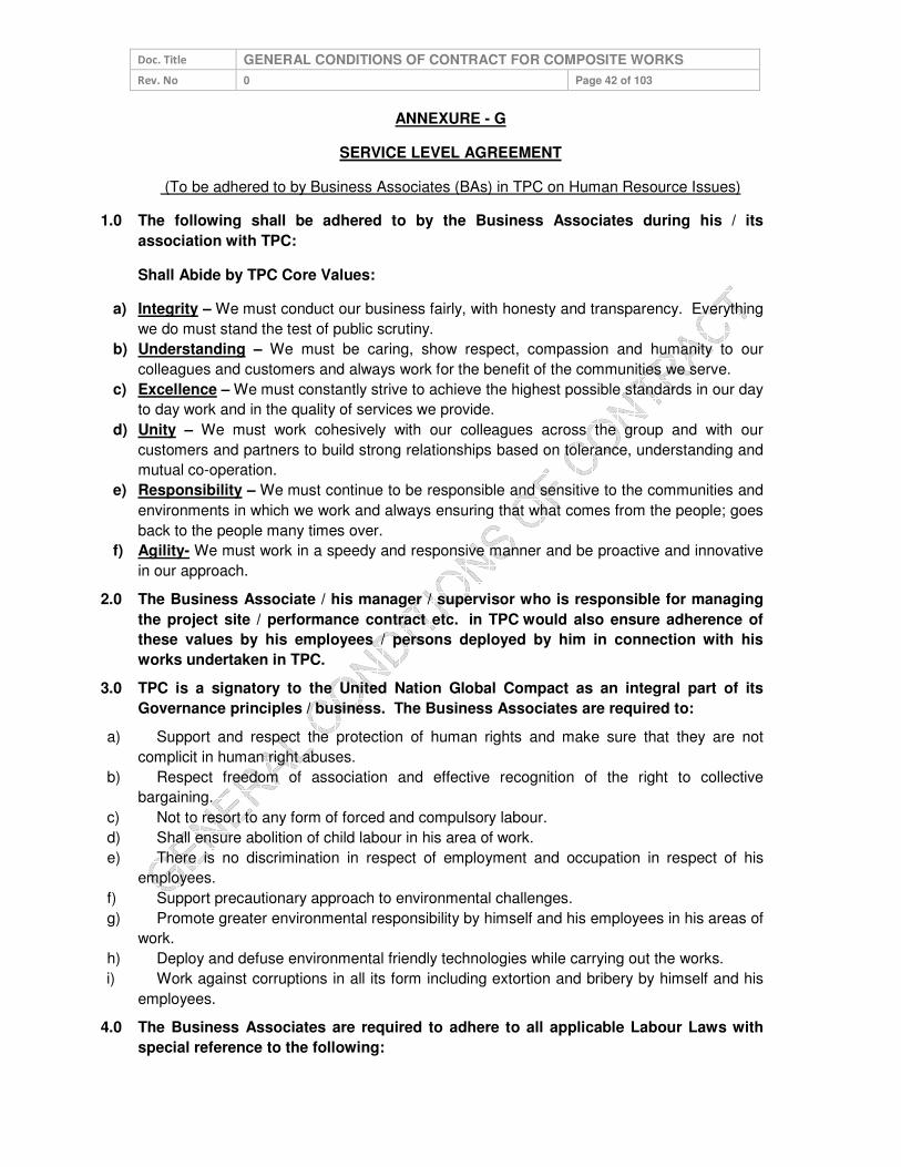
Doc. Title GENERAL CONDITIONS OF CONTRACT FOR COMPOSITE WORKS
Rev. No 0 Page 42 of 103
ANNEXURE - G
SERVICE LEVEL AGREEMENT
(To be adhered to by Business Associates (BAs) in TPC on Human Resource Issues)
1.0 The following shall be adhered to by the Business Associates during his / its
association with TPC:
Shall Abide by TPC Core Values:
a) Integrity – We must conduct our business fairly, with honesty and transparency. Everything
we do must stand the test of public scrutiny.
b) Understanding – We must be caring, show respect, compassion and humanity to our
colleagues and customers and always work for the benefit of the communities we serve.
c) Excellence – We must constantly strive to achieve the highest possible standards in our day
to day work and in the quality of services we provide.
d) Unity – We must work cohesively with our colleagues across the group and with our
customers and partners to build strong relationships based on tolerance, understanding and
mutual co-operation.
e) Responsibility – We must continue to be responsible and sensitive to the communities and
environments in which we work and always ensuring that what comes from the people; goes
back to the people many times over.
f) Agility- We must work in a speedy and responsive manner and be proactive and innovative
in our approach.
2.0 The Business Associate / his manager / supervisor who is responsible for managing
the project site / performance contract etc. in TPC would also ensure adherence of
these values by his employees / persons deployed by him in connection with his
works undertaken in TPC.
3.0 TPC is a signatory to the United Nation Global Compact as an integral part of its
Governance principles / business. The Business Associates are required to:
a) Support and respect the protection of human rights and make sure that they are not
complicit in human right abuses.
b) Respect freedom of association and effective recognition of the right to collective
bargaining.
c) Not to resort to any form of forced and compulsory labour.
d) Shall ensure abolition of child labour in his area of work.
e) There is no discrimination in respect of employment and occupation in respect of his
employees.
f) Support precautionary approach to environmental challenges.
g) Promote greater environmental responsibility by himself and his employees in his areas of
work.
h) Deploy and defuse environmental friendly technologies while carrying out the works.
i) Work against corruptions in all its form including extortion and bribery by himself and his
employees.
4.0 The Business Associates are required to adhere to all applicable Labour Laws with
special reference to the following:

Doc. Title GENERAL CONDITIONS OF CONTRACT FOR COMPOSITE WORKS
Rev. No 0 Page 43 of 103
a) No person below the age of 18 years and no child labour will be engaged directly or
indirectly for executing the work connected with the business of TPC.
b) Minimum wages along with other statutory dues like PF, ESI, etc. as applicable to the
workers shall be made within the prescribed period of 7th / 10th day of the following month.
c) Deduction / deposit / record keeping and all other requirements under Employees PF Act
1952, Employees State Insurance Act 1948 and other applicable acts (if any) shall be
adhered to.
d) Only statutorily authorized deductions (if any) shall be made in accordance with the
relevant statutes.
e) All the provisions of Contract Labour (R&A) Act 1970 shall be complied with in respect of
the workers engaged for TPC work. The work will be commenced only after completing
necessary formalities for obtaining Labour License (if applicable).
f) Necessary registers / records, filing of returns etc. shall be maintained for verification by
Statutory / TPC authorities.
g) Payment of wages shall be made only in presence of and with certification of authorized
representative of TPC or shall be made in the form of cheque / bank transfer to the
employee.
h) During the period of contract, the Business Associate will arrange for deployment of his
supervisor / manager for total supervision and control of the work and their manpower. All
the activities related to their manpower e.g. attendance, leave, wage disbursement etc. will
be done under the supervision & control of Business Associates, While adhering to the
prescribed standard / norms of production / productivity & quality. During execution of the
work, Business Associate shall engage only such qualified / skilled manpower as may be
envisaged / required for ensuring level of production / service into the contract / work order.
i) Clearances as follows shall be obtained from IR & Welfare Group:
i. Clearance for commencement (before start of the work).
ii. No Objection Certificate (after completion / before final settlement).
iii. Copies of PF / ESI Challans shall be deposited with IR & Welfare Group every month
j) The Business Associate shall indemnify TPC from any liabilities under applicable Labour
Statutes.
k) The Business Associate shall ensure safety and health of his employees and shall also
maintain hygienic working environment / condition in his area of work.
l) The Business Associate and his employee shall abide by Laws of Land and shall not
violate any applicable provisions.
m) The Business Associate appreciates with and acquiesces to the right of TPC as principal
employer to fulfil any of his legal obligations, if he fails to do so under applicable labour laws
and deduct the same from his running bills / final payments / enchasing security deposit /
Bank Guarantee as the case may be. If there is any further shortfall TPC has the right to
recover the same from the Business Associate.
n) The Business Associate ensures that person employed by him adhere to the moral and
legal conduct and shall not violate any standard conduct envisaged in the premise of TPC by

Doc. Title GENERAL CONDITIONS OF CONTRACT FOR COMPOSITE WORKS
Rev. No 0 Page 44 of 103
all such as, Transparency, Safety, Discipline, Integrity etc. The Business Associate or his
employees should refrain from corrupt practices, giving or taking bribe in connection with any
TPC business.
5.0 The ‘Statutory Compliance Enforcement System’ in TPC is detailed below for
adherence by all concerned. Corporate IR & Welfare Group will be the process owner
for implementation of the system with the help of concerned Engineer I/c or Officer
I/c.
a) Statutory Compliance being a professed value in TPC Code of Conduct, the concerned
Engineer / Officer in charges are requested to adhere to the provisions and advise
respective Business Associates in their domain to comply in letter and spirit.
b) Immediately after issuance of letter of intent, the authorized representative of the Business
Associate will report to Corporate IR & Welfare group for completion of statutory
requirements.
c) Normally, the work will be started only after ‘Clearance for Commencement of Work (CCW)
is issued by IR & W group to the Business associate. However in exceptional exigencies in
engineer I/c / Officer I/c may direct the Business Associate to start the work and inform IR &
W group about the same. Statutory requirements in this case may be completed parallely.
d) First monthly bill will be released only after producing CCW to the finance department.
Similarly closure of work and final settlement will be affected after issuance of no objection
certificate from IR & W group.
6.0 Requirements for ‘Clearance for Commencement of Work’ (CCW):
a) Submission of filled up Form ‘A’ for database (Annexure-1).
b) Copy of PF Code allocation letter.
c) Copy of ESI Code allocation letter.
d) Submission of duly filled up Form IV CL(R&A) act (In case more than or equals to 20
workers during the period of contract).
e) Submission of duly filled up Form VI A (Notice of Commencement).
f) Copy of insurance cover note under WC Act 1923 (if applicable).
g) Copy of Contract Agreement.
h) Copy of indemnity bond (if applicable).
i) Affidavit with regard to payment of wages through cheque / bank transfer only.
7.0 Requirements during execution of work:
a) Copy of receipt of application for license / license (if applicable).
b) Copy of PF Challan (latest by 26th day of every Month).
c) Copy of ESI Challan (latest by 26th day of every Month).
d) Copy of Wage disbursement sheet / Bank statement.
e) Filing / Maintenance of all statutory registers / reports / returns for inspection by Statutory/
TPC authorities.
f) Certification of wage disbursement by authorized representative of TPC.
g) Copy of ‘Labour Welfare Fund’ deposit certificate / Challan.
h) Insuring safe working practices at the work place.
8.0 Requirements for ‘No Objection Certificate’ (NOC) for closure of work:
a) Submission of duly filled up Form VI A (Notice of Completion).

Doc. Title GENERAL CONDITIONS OF CONTRACT FOR COMPOSITE WORKS
Rev. No 0 Page 45 of 103
b) Copy of Half yearly / Annual return for ESI / PF / CL(R&A).
c) Consolidated copy of wage sheet of last month indicating full & final settlement of all dues
like retrenchment benefit, bonus, leave encashment etc. Copy of individual declaration by
employees in Form X regarding termination of employment.
d) Confirmation certificate regarding filling up of form for transfer / withdrawal of PF by the
concerned workers.
In case any of the above are deviated / not complied with the Letter of Award/Order
shall be liable to be withdrawn / cancelled.
Enclosure:
1) Form A
2) Form X
3) Form XI
4) Form VI A
5) Form XXIV

Doc. Title GENERAL CONDITIONS OF CONTRACT FOR COMPOSITE WORKS
Rev. No 0 Page 46 of 103
FORM (A)
[To be submitted by the Business Associate to the Principal Employer within a week from LoA
issuance]
A. Details of the Agency
1. Name of Agency :
2. Nature of work :
3. Local Address with Ph.No. :
(With Father’s name) :
4. Permanent Address (Full) :
5. PF code no. & Place :
6. ESI Code no. & Place :
7. Name and address of :
Sub-contractor (if any)
B. Details of Work
8. Name of work (as specified in LOI/LOA) :
9. LOI/LOA Nos. & Dates :
10. Period of contract (Specify Dates) :
[Including Extension period, if any] :
11. Work Area [Department / Location] :
12. Name / Cell no. of Officer I/c :
13. Maximum No. of workers and staff to be engaged on any day during the year.
Supervisory Staff :
Workers :
14. Do you have any other contract in TPC : Yes/No
If yes, furnish details:

Doc. Title GENERAL CONDITIONS OF CONTRACT FOR COMPOSITE WORKS
Rev. No 0 Page 47 of 103
15. Details of Workmen’s compensation Policy, if applicable
Name of Insurance Company ……………………………………………………………………………...
………………………………………Policy No ……………………………… Number of persons
covered …………… Period of coverage: From ……………………. To …………………….…..
If no, I hereby undertake the liability arising out of Workmen’s Compensation Act and Rules made there under.
C. Details of workers to be engaged
No. of Workers
S. No. Unskilled* Semi-skilled* Skilled* Clerical / Supervisory
* Number to be indicated
I/We shall fulfill all obligations arising from and under all relevant law in force from time to time. I/We
undertake to keep the TPC indemnified against any loss or liability arising out of failure of my / our
abiding the relevant laws.
The name of my / our representatives is …………………………………………… to enter the TPC
Premises on my behalf.
Date:
(Signature of the Business Associate
or his Authorized Representative)
This Business Associate is / will be engaged in TPC.
(Signature and seal of
Officer I/c of the Work)

Doc. Title GENERAL CONDITIONS OF CONTRACT FOR COMPOSITE WORKS
Rev. No 0 Page 48 of 103
Form X
Undertaking
I _________________________________________________ hereby undertake that all the
dues in respect of my employment with M/s ____________________________________ for
the period of _______________________________ to __________________________have
been settled and final payments including retrenchment benefit have been made to me in full.
( )
______________________________
Date:

Doc. Title GENERAL CONDITIONS OF CONTRACT FOR COMPOSITE WORKS
Rev. No 0 Page 49 of 103
Form XI
Undertaking
With reference to the contract job awarded by M/s The Tata Power Company Ltd to
M/s__________________________________________________________________ vide work
order No.______________________________________________ dated__________________
I _______________________on behalf of
M/s _________________________________________________hereby undertake:
1. that the dues in respect of the workmen/ employee(s) engaged by us for the said contract,
payable as per the provisions of relevant statute pertaining to
i. wages/ salary
ii. PF & ESI, Bhubaneswar Labour Fund
iii. All other statutory obligation
has been paid /settled in full and no amount/ compliance is due/ pending.
2. That in case any dispute / claim is raised by the concerned workers i.r.o. any dues / payments,
M/s ____________________________________ will settle the same on it’s own and such
liability will be borne by M/s ____________________________________________________
3. That M/s _________________________________________ hereby indemnify M/s TPC from
any future liability i.r.o. any statutory obligation in respect of said contract.
Date:
________________________
( )
Authorized Signatory
For M/s _____________________

Doc. Title GENERAL CONDITIONS OF CONTRACT FOR COMPOSITE WORKS
Rev. No 0 Page 50 of 103
FORM- VI A
Notice for Commencement /Completion of contract work
I/We, Sh. / M/s ____________________________________________________ (Name
and Address of the Contractor) hereby intimate that the contract work
_______________________________________________ (name of work) in establishment
of the ________________________________________ (name and address of the
Principal Employer) for which License
No.___________________________________________dated_____________________ha
s been issued to me/us by the Licensing Officer _______________________(name of the
Headquarters), has been commenced / completed with effect from
______________________date / on date.
Signature of Contractor
With Office Seal
The Inspector
__________________________
__________________________

Doc. Title GENERAL CONDITIONS OF CONTRACT FOR COMPOSITE WORKS
Rev. No 0 Page 51 of 103
FORM XXIV
[See Rule 82(1)]
Return to be sent by the Contractor to the licensing Officer (in duplicate)
Half -Yearly Ending_______
1. Name and address of the Contractor
2. Name and address of the Establishment
3. Name and address of the Principal Employer
4. Duration of Contract: From _______________to _________________
5. No. of days during the half year on which
(a) the establishment of the principal employer had worked
(b) the contractor’s establishment had worked
6. Maximum No. of contract labour employed on any day during the half –year:
Men Women Children Total
7. (i) Daily hours of work and spread over
(ii) (a) whether weekly holiday observed and on what day
(b) if so, whether it was paid for
(iii) No. of man – hours of overtime worked
8. No. of man days worked by
Men Women Children Total
9. Amount of wages paid
Men Women Children Total
10. Amount of deductions from wages, if any
Men Women Children Total
Whether the following have been provided –
(i) Canteen : _____________
(ii) Rest rooms : _____________
Doc. Title GENERAL CONDITIONS OF CONTRACT FOR COMPOSITE WORKS
Rev. No 0 Page 52 of 103
(iii) Drinking water : _____________
(iv) Crèches : _____________
(v) First Aid : _____________
Signature of contractor
Place _________________
Date __________________

Doc. Title GENERAL CONDITIONS OF CONTRACT FOR COMPOSITE WORKS
Rev. No 0 Page 53 of 103
ANNEXURE – H
UNDERTAKING FOR COMPETENCE OF WORKMEN
Name of Associate :
Tender No. :
Item :
With reference to the tender mentioned above, I/We _______________________________,
hereby undertake that the workmen/ employee(s) engaged by M/s
__________________________ for the job against said tender shall be competent in all
respect, commensurate to the nature of job.
Date: _____________________________
( )
Authorized Signatory
For M/s
Seal

Doc. Title GENERAL CONDITIONS OF CONTRACT FOR COMPOSITE WORKS
Rev. No 0 Page 54 of 103
ANNEXURE-I
BUSINESS ASSOCIATE FEEDBACK FORM
With an objective to improve our internal processes and systems, and serve you better, we
solicit your valuable feedback & suggestions. It is estimated that it will take about 10 minutes
to complete this survey. We assure you that your feedback shall be kept confidential.
Please send the duly filled feedback form in the "TPC addressed - attached envelop"
You are associated with us as OEMs Service Contractor Material Suppliers Material & Manpower Supplier You are associated with us for Less than 1 year More than 1 year but less than 3 years More than 3 years Your office is located at Bhubaneswar / NCR Within 200 kms from Bhubaneswar More than 200 kms from Bhubaneswar Your nearly turnover with TPC Less than 25 Lacs 25 Lacs to 1 Crore More than 1 Cr.
Additional information
Your Name
Your Designation
Your Organization
Contact Nos.
We once again thank you for your participation in this survey. Please spare 10 minutes to
give your feedback on following pages (Section A to E)
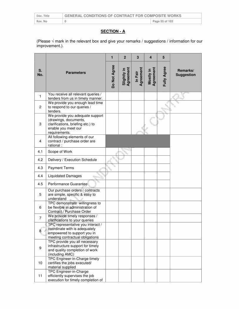
Doc. Title GENERAL CONDITIONS OF CONTRACT FOR COMPOSITE WORKS
Rev. No 0 Page 55 of 103
SECTION - A
(Please √ mark in the relevant box and give your remarks / suggestions / information for our improvement.).
S. No.
Parameters
1 2 3 4 5
Remarks/ Suggestion
Do
No
t A
gre
e
Slig
htl
y i
n
Ag
ree
men
t
In F
air
A
gre
em
en
t
Mo
stl
y in
A
gre
em
en
t
Fu
lly A
gre
e
1 You receive all relevant queries / tenders from us in timely manner.
2 We provide you enough lead time to respond to our queries / tenders.
3
We provide you adequate support (drawings, documents, clarifications, briefing etc.) to enable you meet our requirements.
4 All following elements of our contract / purchase order are rational :
4.1 Scope of Work
4.2 Delivery / Execution Schedule
4.3 Payment Terms
4.4 Liquidated Damages
4.5 Performance Guarantee
5 Our purchase orders / contracts are simple, specific & easy to understand
6 TPC demonstrate willingness to be flexible in administration of Contract / Purchase Order
7 We provide timely responses / clarifications to your queries
8
TPC representative you interact / coordinate with is adequately empowered to support you in meeting contractual obligations
9
TPC provide you all necessary infrastructure support for timely and quality completion of work (including AMC)
10 TPC Engineer-in-Charge timely certifies the jobs executed/ material supplied
11 TPC Engineer-in-Charge efficiently supervises the job execution for timely completion of
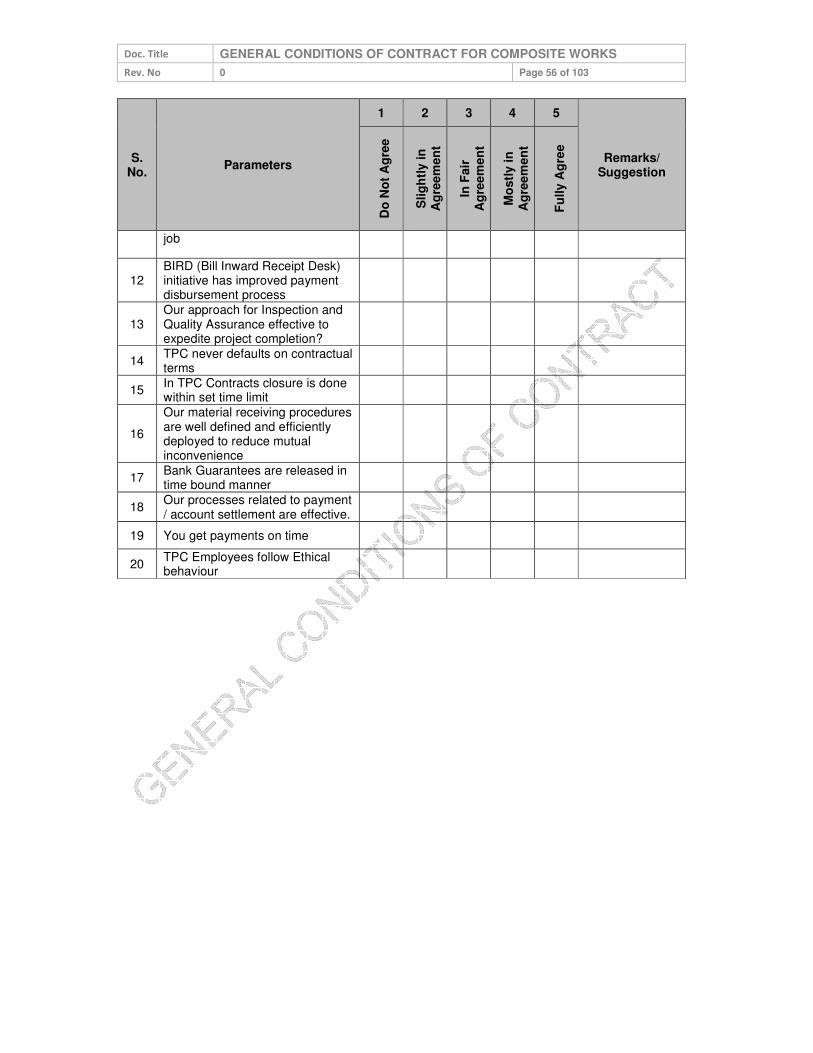
Doc. Title GENERAL CONDITIONS OF CONTRACT FOR COMPOSITE WORKS
Rev. No 0 Page 56 of 103
S. No.
Parameters
1 2 3 4 5
Remarks/ Suggestion
Do
No
t A
gre
e
Slig
htl
y i
n
Ag
ree
men
t
In F
air
A
gre
em
en
t
Mo
stl
y in
A
gre
em
en
t
Fu
lly A
gre
e
job
12 BIRD (Bill Inward Receipt Desk) initiative has improved payment disbursement process
13 Our approach for Inspection and Quality Assurance effective to expedite project completion?
14 TPC never defaults on contractual terms
15 In TPC Contracts closure is done within set time limit
16
Our material receiving procedures are well defined and efficiently deployed to reduce mutual inconvenience
17 Bank Guarantees are released in time bound manner
18 Our processes related to payment / account settlement are effective.
19 You get payments on time
20 TPC Employees follow Ethical behaviour
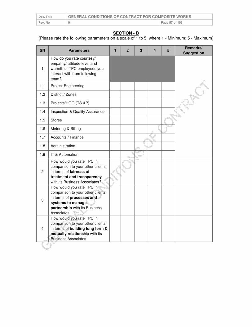
Doc. Title GENERAL CONDITIONS OF CONTRACT FOR COMPOSITE WORKS
Rev. No 0 Page 57 of 103
SECTION - B (Please rate the following parameters on a scale of 1 to 5, where 1 - Minimum; 5 - Maximum)
SN Parameters 1 2 3 4 5 Remarks/
Suggestion
1
How do you rate courtesy/
empathy/ attitude level and
warmth of TPC employees you
interact with from following
team?
1.1 Project Engineering
1.2 District / Zones
1.3 Projects/HOG (TS &P)
1.4 Inspection & Quality Assurance
1.5 Stores
1.6 Metering & Billing
1.7 Accounts / Finance
1.8 Administration
1.9 IT & Automation
2
How would you rate TPC in
comparison to your other clients
in terms of fairness of
treatment and transparency
with its Business Associates?
3
How would you rate TPC in
comparison to your other clients
in terms of processes and
systems to manage
partnership with its Business
Associates
4
How would you rate TPC in
comparison to your other clients
in terms of building long term &
mutually relationship with its
Business Associates

Doc. Title GENERAL CONDITIONS OF CONTRACT FOR COMPOSITE WORKS
Rev. No 0 Page 58 of 103
SECTION–C
Please √ mark in the relevant box and give your remarks / suggestions / information for our improvement.
SNo Parameters
Cert
ain
ly N
O
Pro
ba
bly
NO
Pro
bab
ly Y
ES
Ce
rtain
ly Y
ES
Remarks/ Suggestion
1 Based on your experience with TPC, would you like to continue your relationship with TPC?
2 If someone asks you about TPC, would you talk “positively” about TPC?
3
Would you refer TPC name to others in your community, fraternity and society as a professional & dynamic organization?
SECTION - D
If we ask you to rate us on a scale of 1 to 10, how will you rate TPC, that truly
represents your overall satisfaction with us (please tick appropriate box) -
1 2 3 4 5 6 7 8 9 10

Doc. Title GENERAL CONDITIONS OF CONTRACT FOR COMPOSITE WORKS
Rev. No 0 Page 59 of 103
SECTION – E
Please √ mark in the relevant box and give your remarks / suggestions / information for our
improvement.
Please spare your thoughts for TPC’s improvement in particular areas of weaknesses,
particularly relating to some great practices, attitudes that you have seen elsewhere in Indian
and International Organizations, which you recommend TPC to adopt. Please give your
valuable salient recommendations.
Please spare your thoughts for TPC’s improvement in particular areas of major concerns for
you. We also welcome your suggestions to adopt any best practices, altitudes that you have
observed / experienced elsewhere in Indian/ International organization.
Recommendation Please tick (√) your top 5 expectations out of the following 10 points listed below -
(Please list down improvement you expect from TPC)
Timely payment
1 Flexibility in Contracts/PO
Clarity in PO,s & Contracts
2 Timely response to quarries
Timely certification of works executed
3 Clarity in Specs,drawings,other docs etc
Adequate information provided on website for tender notification, parties qualified etc.
4 Timely receipt of material at site for execution
Performance Guarantee/EMD released in time
5 Inspection & quality assurance support for timely job completion
We thank you for your time and courtesy!!

Doc. Title GENERAL CONDITIONS OF CONTRACT FOR COMPOSITE WORKS
Rev. No 0 Page 60 of 103
ANNEXURE-J
ACCEPTANCE FORM FOR PARTICIPATION IN REVERSE AUCTION EVENT
(To be signed and stamped by the bidder prior to participation in the auction event)
In a bid to make our entire procurement process more fair and transparent, TPC intends to use the
reverse auctions through SAP-SRM tool as an integral part of the entire tendering process. All the
bidders who are found as technically qualified based on the tender requirements shall be eligible to
participate in the reverse auction event.
The following terms and conditions are deemed as accepted by the bidder on participation in
the bid event:
1. TPC shall provide the user id and password to the authorized representative of the bidder.
(Authorization Letter in lieu of the same shall be submitted along with the signed and stamped
Acceptance Form).
2. TPC will make every effort to make the bid process transparent. However, the award decision by
TPC would be final and binding on the supplier.
3. The bidder agrees to non-disclosure of trade information regarding the purchase, identity of TPC,
bid process, bid technology, bid documentation and bid details.
4. The bidder is advised to understand the auto bid process to safeguard themselves against any
possibility of non-participation in the auction event.
5. In case of bidding through Internet medium, bidders are further advised to ensure availability of
the entire infrastructure as required at their end to participate in the auction event. Inability to bid
due to telephone line glitch, internet response issues, software or hardware hangs, power failure
or any other reason shall not be the responsibility of TPC.
6. In case of intranet medium, TPC shall provide the infrastructure to bidders. Further, TPC has sole
discretion to extend or restart the auction event in case of any glitches in infrastructure observed
which has restricted the bidders to submit the bids to ensure fair & transparent competitive
bidding. In case an auction event is restarted, the best bid as already available in the system
shall become the start price for the new auction.
7. In case the bidder fails to participate in the auction event due any reason whatsoever, it shall be
presumed that the bidder has no further discounts to offer and the initial bid as submitted by the
bidder as a part of the tender shall be considered as the bidder’s final no regret offer. Any offline
price bids received from a bidder in lieu of non-participation in the auction event shall be outrightly
rejected by TPC.
8. The bidder shall be prepared with competitive price quotes on the day of the bidding event.
9. The prices as quoted by the bidder during the auction event shall be inclusive of all the applicable
taxes, duties and levies and shall be FOR at TPC site.
10. The prices submitted by a bidder during the auction event shall be binding on the bidder.
11. No requests for time extension of the auction event shall be considered by TPC.
12. The original price bids of the bidders shall be reduced on pro-rata basis against each line item
based on the final all inclusive prices offered during conclusion of the auction event for arriving at
Contract amount.
Signature & Seal of the Bidder

Doc. Title GENERAL CONDITIONS OF CONTRACT FOR COMPOSITE WORKS
Rev. No 0 Page 61 of 103
ANNEXURE-K
To,
DGM (Finance) The Tata Power Company Limited
Bhubaneswar
Sub: e-Payments through National Electronic Fund Transfer (NEFT) OR Real Time
Gross Settlement System (RTGS)
Dear Sir,
We request and authorize you to affect e-payment through NEFT/RTGS to our Bank Account as per the details given below:-
Vendor Code :
Title of Account in the Bank :
Account Type :
(Please mention here whether account is
Savings/Current/Cash Credit)
Bank Account Number :
Name & Address of Bank
:
Bank Contact Person’s Names :
Bank Tele Numbers with STD Code :
Bank Branch MICR Code :
(Please enclose a Xerox a copy of a cheque.
This cheque should not be a payable at par
cheque)
Bank Branch IFSC Code :
(You can obtain this from branch where you
have your account)
Email Address of accounts person (to
:

Doc. Title GENERAL CONDITIONS OF CONTRACT FOR COMPOSITE WORKS
Rev. No 0 Page 62 of 103
send payment information)
Name of the Authorized Signatory :
Contact Person’s Name
Official Correspondence Address
:
:
We confirm that we will bear the charges, if any, levied by our bank for the credit of
NEFT/RTGS amounts in our account. Any change in above furnished information shall be
informed to TPC well in time at our own. Further, we kept TPC indemnified for any loss
incurred due to wrong furnishing of above information.
Thanking you,
For ____________________
(Authorized Signatory)
(Signature with Rubber Stamp)
Certification from Bank:
We confirm that we are enabled for receiving NEFT/RTGS credits and we further confirm
that the account number (specify Bank a/c no.) of (Please mention here name of the account
holder), the signature of the authorized signatory and the MICR and IFSC Code of our
branch mentioned above are correct.
This also is certified that the above information is correct as per Bank record
(Manager’s/ Officers Signature under Bank Stamp)
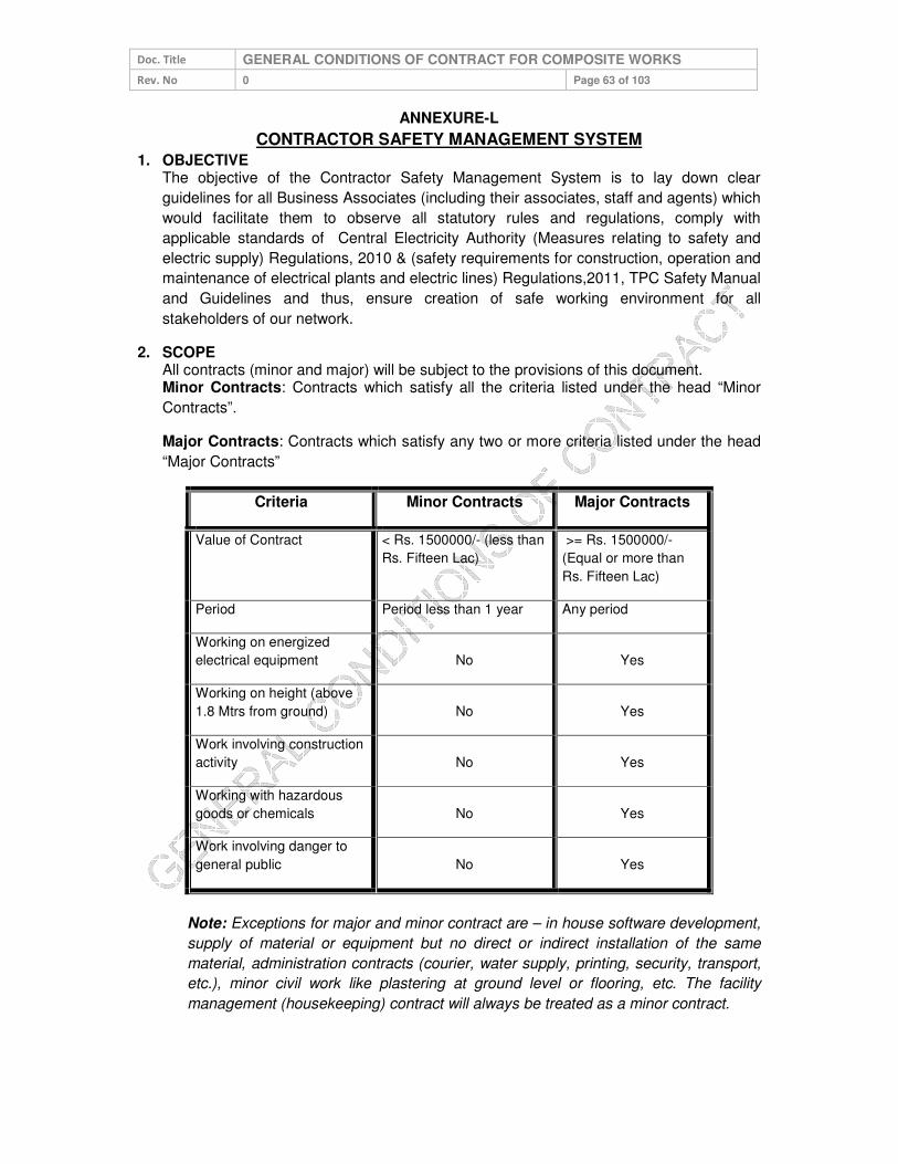
Doc. Title GENERAL CONDITIONS OF CONTRACT FOR COMPOSITE WORKS
Rev. No 0 Page 63 of 103
ANNEXURE-L
CONTRACTOR SAFETY MANAGEMENT SYSTEM
1. OBJECTIVE The objective of the Contractor Safety Management System is to lay down clear
guidelines for all Business Associates (including their associates, staff and agents) which
would facilitate them to observe all statutory rules and regulations, comply with
applicable standards of Central Electricity Authority (Measures relating to safety and
electric supply) Regulations, 2010 & (safety requirements for construction, operation and
maintenance of electrical plants and electric lines) Regulations,2011, TPC Safety Manual
and Guidelines and thus, ensure creation of safe working environment for all
stakeholders of our network.
2. SCOPE All contracts (minor and major) will be subject to the provisions of this document. Minor Contracts: Contracts which satisfy all the criteria listed under the head “Minor
Contracts”.
Major Contracts: Contracts which satisfy any two or more criteria listed under the head
“Major Contracts”
Criteria Minor Contracts Major Contracts
Value of Contract < Rs. 1500000/- (less than
Rs. Fifteen Lac)
>= Rs. 1500000/-
(Equal or more than
Rs. Fifteen Lac)
Period Period less than 1 year Any period
Working on energized
electrical equipment No Yes
Working on height (above
1.8 Mtrs from ground) No Yes
Work involving construction
activity No Yes
Working with hazardous
goods or chemicals No Yes
Work involving danger to
general public No Yes
Note: Exceptions for major and minor contract are – in house software development,
supply of material or equipment but no direct or indirect installation of the same
material, administration contracts (courier, water supply, printing, security, transport,
etc.), minor civil work like plastering at ground level or flooring, etc. The facility
management (housekeeping) contract will always be treated as a minor contract.
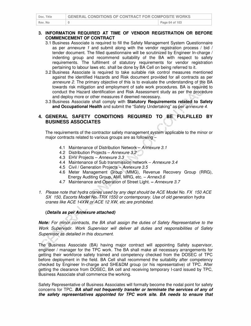
Doc. Title GENERAL CONDITIONS OF CONTRACT FOR COMPOSITE WORKS
Rev. No 0 Page 64 of 103
3. INFORMATION REQUIRED AT TIME OF VENDOR REGISTRATION OR BEFORE COMMENCEMENT OF CONTRACT 3.1 Business Associate is required to fill the Safety Management System Questionnaire
as per annexure 1 and submit along with the vendor registration process / bid / tender document. The filled questionnaire will be scrutinized by Engineer In-charge / indenting group and recommend suitability of the BA with respect to safety requirements. The fulfilment of statutory requirements for vendor registration pertaining to labour laws etc. shall be done by BA Cell on being referred to it.
3.2 Business Associate is required to take suitable risk control measures mentioned against the identified Hazards and Risk document provided for all contracts as per annexure 2. The primary objective of this is to evaluate the understanding of the BA towards risk mitigation and employment of safe work procedures. BA is required to conduct the Hazard identification and Risk Assessment study as per the procedure and deploy more or other measures if deemed necessary.
3.3 Business Associate shall comply with Statutory Requirements related to Safety and Occupational Health and submit the “Safety Undertaking” as per annexure 4.
4. GENERAL SAFETY CONDITIONS REQUIRED TO BE FULFILLED BY BUSINESS ASSOCIATES
The requirements of the contractor safety management system applicable to the minor or major contracts related to various groups are as following –
4.1 Maintenance of Distribution Network – Annexure 3.1 4.2 Distribution Projects – Annexure 3.2 4.3 EHV Projects – Annexure 3.3 4.4 Maintenance of Sub transmission network – Annexure 3.4 4.5 Civil / Generation Projects – Annexure 3.5 4.6 Meter Management Group (MMG), Revenue Recovery Group (RRG),
Energy Auditing Group, AMI, MRG, etc. – Annex3.6 4.7 Maintenance and Operation of Street Light. – Annexure 3.7
1. Please note that hydra cranes used by any dept should be ACE Model No. FX 150 ACE SX 150, Escorts Model No. TRX 1550 or contemporary. Use of old generation hydra cranes like ACE 14XW or ACE 12 XW, etc are prohibited.
(Details as per Annexure attached)
Note: For minor contracts, the BA shall assign the duties of Safety Representative to the
Work Supervisor. Work Supervisor will deliver all duties and responsibilities of Safety
Supervisor as detailed in this document.
The Business Associate (BA) having major contract will appointing Safety supervisor, engineer / manager for the TPC work. The BA shall make all necessary arrangements for getting their workforce safety trained and competency checked from the DOSEC of TPC before deployment in the field. BA Cell shall recommend the suitability after competency checked by Engineer In-charge and SHE&DM group (or his representative) of TPC. After getting the clearance from DOSEC, BA cell and receiving temporary I-card issued by TPC, Business Associate shall commence the working.
Safety Representative of Business Associates will formally become the nodal point for safety concerns for TPC. BA shall not frequently transfer or terminate the services of any of the safety representatives appointed for TPC work site. BA needs to ensure that

Doc. Title GENERAL CONDITIONS OF CONTRACT FOR COMPOSITE WORKS
Rev. No 0 Page 65 of 103
Safety representative is available at all points of time; failing which the work being carried out in the interim (period when Safety representative is not available) shall be treated as working under improper supervision and due penal provisions shall be initiated against the BA. BA will be required to provide all applicable infrastructure and power to ensure smooth working of the safety representative to maintain a sound safety management system. In all contracts safety representative will not be assigned any other activity at site apart from the works related to safety management. The duties are detailed in clause 5.5 of this document. TPC will be auditing the facilities provided to the BA`s safety team time to time.
The Safety Representative of the BA shall be required to meet and follow the instructions of the Engineer In-charge and SHE&DM Group of TPC. He shall be responsible for providing the MIS and/or any other relevant information, as and when desired, within the stipulated time frame as per the requirements of TPC. Any non-conformance to safety will lead to the negative marking or issue of safety violation challan/ tokens which shall affect the monthly evaluation and performance of BA.
All contracts where BA has to depute vehicle for their staff and equipment to move from one location to other, the BA shall ensure that vehicle complies all required statutory clearances and requirement as per The Motor Vehicle Act, 1988 as well as TPC Road Safety Policy and are in good & safe state of working.
5. QUALIFICATION AND EXPERIENCE OF THE SAFETY AND SITE PERSONNEL
Qualification and experience required for the safety and site personnel are as following:
5.1 Safety Supervisor: It is mandatory that educational qualification of safety supervisor be ITI (of relevant trade) / Diploma (Any branch of engineering) and he has a working experience on electrical system / relevant field of work at least 5 yrs for ITI and 3 years for Diploma holder. Having formal experience of the safety systems will be an added advantage
5.2 Safety Engineer: It is mandatory that educational qualification of safety engineer be at least Diploma (relevant branch) and he has working experience on electrical system of at least 3 yrs. Having the formal experience of the safety systems will be an added advantage.
5.3 Safety Manager: The educational qualification of safety manager should be graduate engineer with working experience on electrical system / network of at least 3 yrs. OR Diploma in Industrial Safety with working experience of 05 years including at least 02 years on electrical network.
However, clause 5.1, 5.2 and 5.3 are not applicable for minor contracts. In such cases, BA shall assign the duties of Safety Representative to the Work Supervisor. Work Supervisor will deliver required duties of Safety Representative (as per clause 5.5) in addition to other duties without diluting the importance of safety.
5.4 Site Skilled Personnel: For all responsibility related to site activities and operations, the BA shall employ only qualified and skilled persons and shall comply the provisions of section 19 & 29 of Central Electricity Authority (Measures relating to safety and electric supply) Regulations, 2010. Persons holding valid approvals only by any Government approved agency or a competency assessment panel or a team set up by TPC shall be

Doc. Title GENERAL CONDITIONS OF CONTRACT FOR COMPOSITE WORKS
Rev. No 0 Page 66 of 103
allowed to perform the High Risk / High Hazard activities (refer page 1). The skill / qualification required for the electrician and electrical supervisor are given in annexure 5. The contracts related to maintenance of Distribution Network, Distribution Projects, EHV Projects, maintenance of Sub-Transmission Network, MMG & EAG, maintenance and operation of street lights, shall preferably have at least 20 per cent of ITI qualified electricians in the first year of the contract. This figure shall preferably be incremented by 15 per cent every subsequent year.
Note: For the competency assessment may please refer the work instructions. An employee shall have to necessarily undergo the competency assessment check once in every eighteen months.
5.5 Requirements from the Safety Representative(s) of the Business Associate: 5.5.1 Safety training of 2 hrs/employee/month and one day of safety induction training
to all new employees joining the BA will be conducted by the BA as per Safety training modules of TPC.
5.5.2 Safety Talk / tool box talk before start of shift to BA employees. 5.5.3 Ensuring the availability & proper usage of the standard safety equipment (PPE) 5.5.4 Periodic inspection of PPE to ensure their serviceability and maintaining the
10% buffer stock of standard PPEs. 5.5.5 Ensuring the adherence to standard operating procedures of TPC as mentioned
in TPC Safety standard and O & M and concerned function’s manual. 5.5.6 Safety inspections / audits as per the process of TPC 5.5.7 Working in close coordination SHE&DM Group of TPC. 5.5.8 Reporting of unsafe acts, unsafe conditions, near miss, incident or accident to
Engineer In-Charge and SHE&DM Group of TPC immediately after its occurrence.
5.5.9 Regular HIRA at site and comply the control measures as stated in the detailed HIRA as per the annexure 2. Also deployment of JSA based checklist shall be ensured.
5.5.10 Ensuring compliance with safety and other laws as may be applicable and providing for safety assurance.
5.6 Training and Syllabus: The BA shall not deploy any person at work place / site or send newly recruited personnel directly to DOSEC for competency assessment without Safety Induction Training.
5.6.1 All new BA employees have to necessarily undergo one and half days Safety training and Competency assessment at training centre of BA cell. This training will be conducted once in a week. After the completion of Safety training & Competency assessment I-card will be issued to all competent BA employees
5.6.2 BA is expected to initially train and judge the capability of the workman at his own end before further recommending the workmen for Competency assessment. If any BA workman sent for competency assessment. In case any BA workman fails in the Competency test at DOSEC, it will be deemed that BA has not imparted sufficient training at his end and actual cost of training ₹ 7500/ BA employee/ failed attempt will be recovered. 5.6.3 The workers who have imparted Safety Training and issued I-Cards of TPC, are not deployed at TPC worksites/ voluntarily left the job by workers/ used somewhere else other than TPC by the BA, in that case Management reserves the rights to intervene and recover the actual cost of training i.e. ₹ 7500/BA employee. (Exempted for attrition rate of BA workers less than or equal to 10% of total workforce deployed at TPC)

Doc. Title GENERAL CONDITIONS OF CONTRACT FOR COMPOSITE WORKS
Rev. No 0 Page 67 of 103
5.7 It is desired that Safety representative of the BA to impart the general safety training to each employee of duration 2 hrs per month. The training will be organized at BA level and the record to be sent to engineer in-charge and SHE&DM group of TPC every month. Please refer schedule and syllabus in annexure 6.
List of Personal Protective Equipment (PPE) and Maintenance schedule: BA shall commence the project or any work only when the required PPE are made available to the team of employees involved in the work. Each PPE of BA shall be checked / inspected by the safety representative / supervisor at zone before the work start or as prescribed in the list. Safety representative shall regularly check the healthiness of each PPE allocated to lineman. Suitable record shall be maintained at zone. Defective PPE shall be immediately replaced or within 24 hours by the BA. In no case linemen or any other official of BA may be allowed to work with defective PPE. It is preferred that BA ensures minimum stock of each PPE at zone for immediate replacement with defective one. The PPE shall be IS / BS / CE marked and exactly as per the standard or specification mentioned in the annexure 7. Working without PPE / non-standard PPE shall be treated as safety violation and penalty as stated in section 6.0 of this document. If TATA POWER- DDL finds that BA has not provided the adequate / appropriate PPE to their staff, TPC reserves the rights to stop the work and call the BA to provide appropriate PPEs at the risk. If the BA fails to provide the required PPEs at the risk then the same shall be provided by TPC at the actual cost of the PPE. The amount shall be charged to BA and same shall be first recovered from the current bill of BA or any future payment to be made to BA. In the event of any balance amount still left for recovery, the same shall be adjusted against retention amount or by invoking bank guarantee submitted by BA.
5.8 Safety Audit / Inspection & HIRA: The BA shall get the required safety inspection / audit conducted by his technical team comprising of safety representative as per the annexure 8. The safety representative will be required to conduct the HIRA (Hazard Identification and Risk Assessment) as per annexure 2 of the process and work undertaken at least two times in a year or every time if a new process / activity / machine is introduced or whenever an accident take place. The risk identified to be addressed suitably with –
• Engineering Control
• Management Control, and
• Personal Protective Equipment.
The safety representative of BA shall inform and educate for the identified risk and hazard control methods to employees, supervisor and engineer as well as the engineer in-charge and SHE&DM group of TPC.
5.9 Safety Performance and Safety MIS: The BA shall maintain good practice of safety all through the contract duration. Safety shall always be of paramount importance during the contract period. Safety performance will be monitored on yearly basis throughout the period and no relaxation will be given for bad performance. BA with good track record and excellent performance will be rewarded suitably as per clause 6.0 of this document. The BA has to provide monthly “Performance Report – Safety” to engineer in-charge and SHE&DM group TPC this shall be part of monthly bill along with training details. Performa of the report is enclosed as annexure 9.
5.10 Pre – Employment Medical Check-up and Fitness of employees engaged for the
critical works: The BA shall submit the health fitness certificate for all those workers involved in climbing the pole or working at height for following diseases:
5.10.2 Epilepsy

Doc. Title GENERAL CONDITIONS OF CONTRACT FOR COMPOSITE WORKS
Rev. No 0 Page 68 of 103
5.10.3 Colour blindness 5.10.4 Deafness 5.10.5 Vertigo & height phobia
Every year BA will give an undertaking stating that all the employees are fit to work and have not developed aforesaid diseases. The Record of such medical check-ups shall be submitted to BA Cell before issue of temporary identity card. The records shall be maintained at BA Cell. All such medical check-ups shall be repeated once in a year for all workers involved in climbing the pole or working on electrical network.
6. REWARD AND PUNITIVE MEASURES
6.1 To support the enforcement of good SHE & DM practices by the Business Associate and to eliminate repeated or continuing safety violations, use of appropriate reward and punitive measures shall be made. Each unsafe act or violation of the safety guidelines as described in the Safety Manual of the TPC will be audit criteria of this system. Broadly the measures identified are following:
6.1.1 Working without PPE/ Safety Gadgets 6.1.2 Working without proper tools and tackles, barricading, Poor condition of
Crane / Hydra / Vehicle, using without certification / Licence, Incompetent driver/ Helper
6.1.3 Working without creation of effective safety zone 6.1.4 Improper Supervision at worksite, Lineman/ Supervisor working without
competency 6.1.5 Working without adherence to PTW process or authorization/ not
adherence to SOPs / W.I. of TPC. 6.1.6 Improper Working at height equal to or above 1.8 mtrs without taking
proper fall protection measures/ Poor condition of Ladder
6.2 Measures of Reward and Punitive Measures
The Engineer In-Charge, NSO, SC, ASOs, CSI / SIs and SHE &DM group will conduct the surprise audits of the work / project and if any non-conformance is found the same will be booked and entered in the format “Safety Violation Record” annexure 10. The flow of the information is given below:
Safety Violation Escalation & Monitoring process
Action Responsibility
Safety Violation form has been filled and counter foil sent to
SHE&DM team for information. The main form is to be given
to BA supervisor / Engineer in-charge. (Automatically
generated if Site audit done through Mobile App.)
Engineer In-charge/ NSO /
SC / SHE&DM Group /CSI/
ASO/ Any authorised TPC
official.
↓ Entry of the violation in the master record and sending the
information to concerned Manager, HoG, HoD, Head and
Chief (O &S). (Automatically generated if Site audit done
through Mobile App.).
SHE&DM Group
↓
Forwarding the information Centralized Account Payable
(CAPS) for amount deduction from the current bill of the BA,
Engineer In-charge
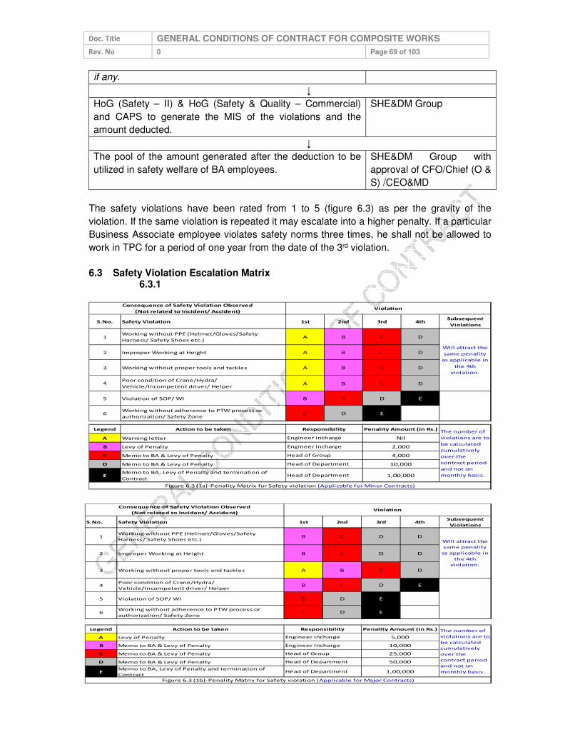
Doc. Title GENERAL CONDITIONS OF CONTRACT FOR COMPOSITE WORKS
Rev. No 0 Page 69 of 103
if any.
↓
HoG (Safety – II) & HoG (Safety & Quality – Commercial)
and CAPS to generate the MIS of the violations and the
amount deducted.
SHE&DM Group
↓
The pool of the amount generated after the deduction to be
utilized in safety welfare of BA employees.
SHE&DM Group with
approval of CFO/Chief (O &
S) /CEO&MD
The safety violations have been rated from 1 to 5 (figure 6.3) as per the gravity of the
violation. If the same violation is repeated it may escalate into a higher penalty. If a particular
Business Associate employee violates safety norms three times, he shall not be allowed to
work in TPC for a period of one year from the date of the 3rd violation.
6.3 Safety Violation Escalation Matrix 6.3.1
S.No. Safety Violation 1st 2nd 3rd 4thSubsequent
Violations
1Working without PPE (Helmet/Gloves/Safety
Harness/ Safety Shoes etc.)A B C D
2 Improper Working at Height A B C D
3 Working without proper tools and tackles A B C D
4Poor condition of Crane/Hydra/
Vehicle/Incompetent driver/ HelperA B C D
5 Violation of SOP/ WI B C D E
6Working without adherence to PTW process or
authorization/ Safety ZoneC D E
Legend Action to be taken
A Warning letter
B Levy of Penalty
C Memo to BA & Levy of Penalty
D Memo to BA & Levy of Penalty
EMemo to BA, Levy of Penalty and termination of
Contract
Figure 6.3 (1a)-Penality Matrix for Safety violation (Applicable for Minor Contracts)
10,000
Head of Department 1,00,000
Consequence of Safety Violation Observed
(Not related to Incident/ Accident)Violation
Will attract the
same penality
as applicable in
the 4th
violation.
Responsibility Penality Amount (in Rs.)The number of
violations are to
be calculated
cumulatively
over the
contract period
and not on
monthly basis.
Engineer Incharge Nil
Engineer Incharge 2,000
Head of Group 4,000
Head of Department
S.No. Safety Violation 1st 2nd 3rd 4thSubsequent
Violations
1Working without PPE (Helmet/Gloves/Safety
Harness/ Safety Shoes etc.)B C D D
2 Improper Working at Height B C D D
3 Working without proper tools and tackles A B C D
4Poor condition of Crane/Hydra/
Vehicle/Incompetent driver/ HelperB C D E
5 Violation of SOP/ WI C D E
6Working without adherence to PTW process or
authorization/ Safety ZoneC D E
Legend Action to be taken
A Levy of Penalty
B Memo to BA & Levy of Penalty
C Memo to BA & Levy of Penalty
D Memo to BA & Levy of Penalty
EMemo to BA, Levy of Penalty and termination of
Contract
Figure 6.3 (1b)-Penality Matrix for Safety violation (Applicable for Major Contracts)
Engineer Incharge 10,000
Head of Group 25,000
Head of Department 50,000
Consequence of Safety Violation Observed
(Not related to Incident/ Accident)Violation
Will attract the
same penality
as applicable in
the 4th
violation.
Responsibility Penality Amount (in Rs.) The number of
violations are to
be calculated
cumulatively
over the
contract period
and not on
monthly basis.
Engineer Incharge 5,000
Head of Department 1,00,000

Doc. Title GENERAL CONDITIONS OF CONTRACT FOR COMPOSITE WORKS
Rev. No 0 Page 70 of 103
Once the BA reaches the “BLACK” (color – “5”) category, i.e. highest level of safety violation,
“Termination” notice to BA will be issued from the office of the Head of Department
(equivalent to Addl GM/ GM/ Sr. GM level) and further, if required, continuation / extension of
contract will only be initiated by Functional Head of the department (equivalent to Sr. GM /
VP level) and approved by CEO & MD. Till the extension, the contract will remain
suspended.
TPC encourages the reportage of the safety violation during the contract work by BA. Any
TPC employee can register a safety violation against the BA in the “Safety Violation Form”
annexure 10. Initially the observer has to fill the form and handover the counterfoil (lower
portion) of the document to the supervisor of the BA, inform the site engineer of TPC and
send the top portion of the Safety Violation Form to SHE&DM group for the further
necessary action against the BA. The cumulative nos. of Safety Violations pertaining to
any particular BA shall be calculated on yearly basis.
Safety violations resulting in incident / accident will be treated as per gravity of the injury /
fatality and its impact as well as type i.e. minor or Major. Consequences of incident /
accident are shown in the matrix (figure 6.3(2) for major and 6.3(3) for minor) below. In case
of any accident, findings and recommendations of Accident Enquiry Committee will be final
and binding and will supersede the arbitration clause of GCC.
Sl. No Type of the injury 1st 2nd 3rd 4th
1 Slight injury (First Aid Case)
2Minor injury (No or Hospitalization less then
48 Hrs)F G G H
3Major injury (Bone injury or burn or
Hospitalization more then 48 Hrs)G G H I
4 Single fatality J K
5Multiple fatalities (Two or more fatalities
during one event)K
Legend Action to be taken Penalty (in Rs.)
F Memo to BA and levy of penalty 5,000/-
G Memo to BA and levy of penalty 20,000/-
H Memo to BA and levy of penalty 50,000/-
I Memo to BA and levy of penalty 2,00,000/-
J Memo to BA and levy of penalty 5,00,000/-.
KMemo to BA, levy of penalty, termination of
contract and black listing of BA 10,00,000/-
Figure 6.3 (2) - Penalty Matrix for Incident / Accident in Major Contracts
Responsibility
The number of
violations are to be
calculated
cumulatively over the
contract period and
not on monthly basis.
Engineer Incharge
Head of Group
Head of Group
Head of Department
Head of Department
Functional Head
Consequence Of an Incident / Accident
(In case of MAJOR contract)Incident / Accident
Actio
n
Req
uired
F(Strengthening of process through continuous improvement in the w ork procedure)
Take risk red
uctio
n
measu
resIn
tolerab
le
(For example: In major contracts, if there is first incidence of major injury say bone injury (Cat. 3)
where worker was hospitalized for more than 48 hrs then a penalty of amount Rs.20000/- will be
deducted from the current bill produced for the payment. This penalty will be similar for first two
incidents. However, it will increment to next higher category i.e. Rs. 50,000/- on subsequent incidents
as per the above matrix)
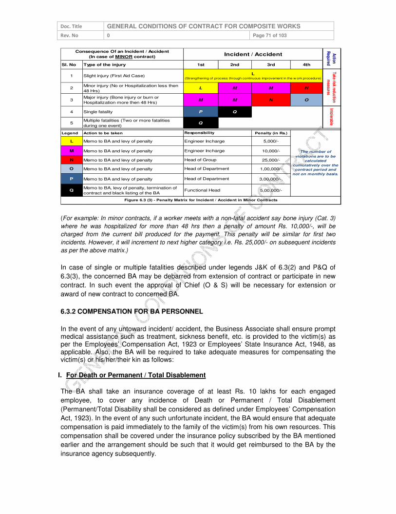
Doc. Title GENERAL CONDITIONS OF CONTRACT FOR COMPOSITE WORKS
Rev. No 0 Page 71 of 103
Sl. No Type of the injury 1st 2nd 3rd 4th
1 Slight injury (First Aid Case)
2Minor injury (No or Hospitalization less then
48 Hrs)L M M N
3Major injury (Bone injury or burn or
Hospitalization more then 48 Hrs)M M N O
4 Single fatality P Q
5Multiple fatalities (Two or more fatalities
during one event)Q
Legend Action to be taken Penalty (in Rs.)
L Memo to BA and levy of penalty 5,000/-
M Memo to BA and levy of penalty 10,000/-
N Memo to BA and levy of penalty 25,000/-
O Memo to BA and levy of penalty 1,00,000/-
P Memo to BA and levy of penalty 3,00,000/-.
QMemo to BA, levy of penalty, termination of
contract and black listing of the BA 5,00,000/-
Engineer Incharge
Engineer Incharge
Head of Group
Head of Department
Head of Department
Functional Head
Figure 6.3 (3) - Penalty Matrix for Incident / Accident in Minor Contracts
The number of
violations are to be
calculated
cumulatively over the
contract period and
not on monthly basis.
Responsibility
IntolerableTake risk reduction
measures
Consequence Of an Incident / Accident
(In case of MINOR contract)Incident / Accident
Action
Required
L(Strengthening of process through continuous improvement in the w ork procedure)
(For example: In minor contracts, if a worker meets with a non-fatal accident say bone injury (Cat. 3)
where he was hospitalized for more than 48 hrs then a penalty of amount Rs. 10,000/-, will be
charged from the current bill produced for the payment. This penalty will be similar for first two
incidents. However, it will increment to next higher category i.e. Rs. 25,000/- on subsequent incidents
as per the above matrix.)
In case of single or multiple fatalities described under legends J&K of 6.3(2) and P&Q of
6.3(3), the concerned BA may be debarred from extension of contract or participate in new
contract. In such event the approval of Chief (O & S) will be necessary for extension or
award of new contract to concerned BA.
6.3.2 COMPENSATION FOR BA PERSONNEL
In the event of any untoward incident/ accident, the Business Associate shall ensure prompt medical assistance such as treatment, sickness benefit, etc. is provided to the victim(s) as per the Employees’ Compensation Act, 1923 or Employees’ State Insurance Act, 1948, as applicable. Also, the BA will be required to take adequate measures for compensating the victim(s) or his/her/their kin as follows:
I. For Death or Permanent / Total Disablement
The BA shall take an insurance coverage of at least Rs. 10 lakhs for each engaged
employee, to cover any incidence of Death or Permanent / Total Disablement
(Permanent/Total Disability shall be considered as defined under Employees’ Compensation
Act, 1923). In the event of any such unfortunate incident, the BA would ensure that adequate
compensation is paid immediately to the family of the victim(s) from his own resources. This
compensation shall be covered under the insurance policy subscribed by the BA mentioned
earlier and the arrangement should be such that it would get reimbursed to the BA by the
insurance agency subsequently.

Doc. Title GENERAL CONDITIONS OF CONTRACT FOR COMPOSITE WORKS
Rev. No 0 Page 72 of 103
II. For Permanent Partial Disablement and Temporary Total Disablement
The compensation in this case will be as per provisions of the Employees’ Compensation
Act, 1923 or Employees’ State Insurance Act, 1948, as applicable.
Accordingly, the BA shall obtain a suitable Insurance Policy on award of Contract and submit
documentary evidence of the policy to the BA Cell before commencement of work. The BA
shall ensure that the Insurance policy is active at all times and all employees are covered in
all respects till the conclusion of contract period or till working with TPC. The BA shall submit
a copy of the policy after periodic renewals to the BA Cell.
However, on occurrence of such unfortunate incident, if it is found that the victim(s) is/are not
covered under any insurance policy, the BA shall be liable to pay the entire sum of Rs. 10
lakhs from his own resources.
Further, in case of an accident resulting in Death or Permanent / Total Disablement while on
duty, the appointed BA Nodal Officer will ensure that the BA complies with all statutory
provisions and benefits i.e. PF, Compensation, Gratuity etc., and that all these are made
available to the employees’ nominee(s) as per the stipulated timelines.
6.3.3 TPC rewards the BA with good track record of safety management. It is proposed that
BA complying with Contractors Safety Management, Safety Manual and Safety process will
be rewarded suitably as per the procedure, rule and regulations of the TPC. In any case
major accident is reported during an assessment period BA will not be eligible for this reward
scheme. Assessment of contracts will be once in year. Generally the assessment cycle is
calendar year and guidelines will be declared time to time.
Abbreviations Used in the Document
TPC The Tata Power Company Ltd
BA Business Associate
HIRA Hazard Identification & Risk Assessment
JSA Job Safety Analysis
EHV Extra High Voltage
SHE&DM Safety, Occupation Health, Environment & Disaster
Management
MMG Meter Management Group
EAG Energy Audit Group
PPE Personal Protective Equipment
SOP Standard Operating Procedures
CSI/SI Circle Safety In-charge / Safety In-charge
ASO Area Safety Officer
NSO Nodal Safety Officer
SC Safety Coordinator
HoG / HoD Head of Group / Head of Department
AGM / GM / VP Assistant General Manager / General Manager / Vice
President

Doc. Title GENERAL CONDITIONS OF CONTRACT FOR COMPOSITE WORKS
Rev. No 0 Page 73 of 103
CFO / Chief (O & S)/
CEO & MD
Chief Finance Officer / Chief (Operating & Safety) / Chief
Executive Officer & Managing Director
COS Corporate Operation Services
CAP Centralized Account Payable System
PTW Permit To Work
GCC General Conditions of Contract.
- END -
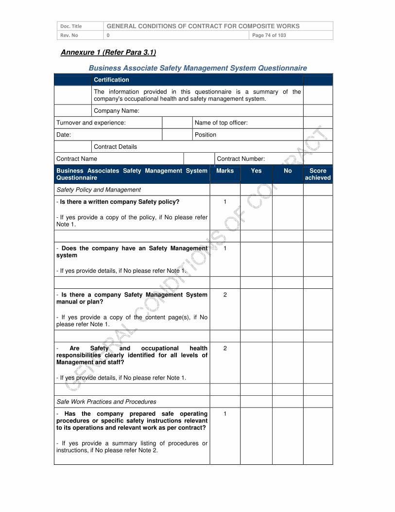
Doc. Title GENERAL CONDITIONS OF CONTRACT FOR COMPOSITE WORKS
Rev. No 0 Page 74 of 103
Annexure 1 (Refer Para 3.1)
Business Associate Safety Management System Questionnaire
Certification
The information provided in this questionnaire is a summary of the company's occupational health and safety management system.
Company Name:
Turnover and experience: Name of top officer:
Date: Position
Contract Details
Contract Name Contract Number:
Business Associates Safety Management System Questionnaire
Marks Yes No Score achieved
Safety Policy and Management
- Is there a written company Safety policy?
- If yes provide a copy of the policy, if No please refer Note 1.
1
- Does the company have an Safety Management system
- If yes provide details, if No please refer Note 1.
1
- Is there a company Safety Management System manual or plan?
- If yes provide a copy of the content page(s), if No please refer Note 1.
2
- Are Safety and occupational health responsibilities clearly identified for all levels of Management and staff?
- If yes provide details, if No please refer Note 1.
2
Safe Work Practices and Procedures
- Has the company prepared safe operating procedures or specific safety instructions relevant to its operations and relevant work as per contract?
- If yes provide a summary listing of procedures or instructions, if No please refer Note 2.
1

Doc. Title GENERAL CONDITIONS OF CONTRACT FOR COMPOSITE WORKS
Rev. No 0 Page 75 of 103
Certification
- Comments
- Is there a register of injury or accident? - If yes provide a copy (format)
1
- Is there a documented incident or accident investigation procedure?
- If yes provide a copy of a standard incident report form, if No please refer Note 2.
- Comments
1
Safety Training
- Describe how occupational health and safety training is conducted in your company
If No please refer Note 1.
2
- Is a record maintained of all training and induction programs undertaken for employees in your company?
- If yes provide examples of safety training records, if No please refer Note 2.
1
- Are regular safety inspections / audits are undertaken at worksites?
-If yes provide details (formats), if No please refer Note 3.
1
- Is there a procedure by which employees can report hazards at workplaces?
- If yes provide details if No please refer Note 1.
1
Safety Monitoring
- Is there an officer / supervisor responsible for monitoring workplace / worksite safety?
1

Doc. Title GENERAL CONDITIONS OF CONTRACT FOR COMPOSITE WORKS
Rev. No 0 Page 76 of 103
Certification
- If yes provide details
Safety Performance Monitoring
- Are employees regularly provided with information on company health and safety performance?
- If yes provide details
1
- Has the company ever been convicted of an occupational health and safety offence?
- If yes provide details
NO Marks (Negative mark ONE for each
case)
- Has there been any major accident of employee at TPC site in past
NO Marks (Negative mark ONE for each
case
- Has there been any fatal accident of employee at TPC site in past.
- (Note: Bid evaluation committee has to take cognizance of the incident and shall evaluate the bid only after formal approval of competent authority i.e. CTO.
- In case of yes please refer Note 4.
NO Mark (Negative mark FIVE
for each case)
Minimum of 75% marks is required for qualification. Total Marks achieved
Company Reference
1. Name of company 2. Name of company
Note
1: If company does not have formal procedure on Safety Management System than vendor
may submit proposed Safety road map along with safety action plan and brief safety policy
on his letter head signed by head of the organization.
2: The vendor may submit the same in the Safety Action Plan.
3: The vendor may utilize the same format of TPC or on request SHE&DM group will assist
the vendor in developing the audit system. For other points also vendor may take the
assistance of SHE&DM group for development of Safety management system.

Doc. Title GENERAL CONDITIONS OF CONTRACT FOR COMPOSITE WORKS
Rev. No 0 Page 77 of 103
4: The vendor may submit the Safety Improvement Plan and Safety Action Plan for his
employees based on following points.
i. Action plan for enhancing safety awareness
ii. Action plan for safety training of employee
iii. Action plan for increasing safety audit in field
iv. Action plan for provision and utilization of safety PPE.
v. Action plan for fatality reduction.
vi. Action plan for enhanced supervision at site
vii. Action plan for making employee more responsible and accountable for
safety.
viii. Action plan for availability and utilization of all required tool and equipment.
ix. Safety Improvement done in last two years, specially highlighting those which
have been taken after the fatal accident along with results.
x. Safety initiatives planed or started recently.
xi. Any other point.
Based on above points and documentary evidences vendor will be required to submit a
detailed report in support of his bid. The bid evaluation committee and competent authority
will scrutinize the facts and the evidence submitted. If found satisfactory competent authority
i.e. CTO may accord his approval for bid opening otherwise his tender shall be disqualified.

Doc. Title GENERAL CONDITIONS OF CONTRACT FOR COMPOSITE WORKS
Rev. No 0 Page 78 of 103
Annexure 2 (Refer Para 3.2 and 5.8)
Risk Assessment Form
Specific Task/Activity
Potential Hazards/Conseque
nces
Class of
Risk Control Measures
Working at Height Fall from height 2
1. Mandatory usage of JSA checklist prior to start of work
2. Use appropriate ladder
3. Use full body safety harness having double lanyard.
4. Use Electrical Safety Shoes if working on electrical network otherwise use safety shoes.
5. Use Safety helmet.
6. Use PPE as per the annexure 7 of this CSM document
7. Refer Work instruction related to Working at Height for other details
8. Use of metal scaffold to be ensured in height work (cup lock type)
9. Deploy competent workforce who are medically fit
Business Associate:
Scope of the work:
BA’s Representative:
Telephone:
Signature:
Date:

Doc. Title GENERAL CONDITIONS OF CONTRACT FOR COMPOSITE WORKS
Rev. No 0 Page 79 of 103
Specific Task/Activity
Potential Hazards/Conseque
nces
Class of
Risk Control Measures
Working on electrical equipment / network
Electric flash / electrocution
3
1. Mandatory usage of JSA checklist prior to start of work
2. Use Electrical Safety Shoes while working on electrical network.
3. Use Electrical Safety gloves of appropriate voltage rating.
4. Use face shield / visor attached with helmet.
5. Use Safety helmet.
6. Use PPE as per the annexure 7 of this CSM document
7. Mandatory usage of Insulated tools & tackles on electrical system
8. Mandatory compliance for Lock Out & Tag out system. Refer Work instruction related to Working on electrical equipment / network for other details
Excavation / Civil work
Collapse of soil, Fall in excavated pit leading to Injury
2
1. Use safety shoes.
2. Use Safety helmet.
3. Use PPE as per the annexure 7 of this CSM document
4. Hard Barricading of the worksite.
5. Refer Work instruction related to excavation / civil work for other details
Material lifting & Mechanical Erection work
Fall of material/object, Topple of crane,
2
1. Mandatory compliance of crane checklist
2. Visual condition check of lifting tools and tackles such as wire rope sling,belt sling, chain, pulley block, D-shackles, etc. shall be ensured.
3. The operator’s physical fitness and alertness should be judged by sup. / EIC.
4. Use PPE as per the annexure 7 of this CSM document
5. Refer Work instruction related to Material lifting & Mechanical Erection work
Road Safety Road Accidents 3
1. Mandatory compliance of TPC Road Safety policy W07(COR-P-12)

Doc. Title GENERAL CONDITIONS OF CONTRACT FOR COMPOSITE WORKS
Rev. No 0 Page 80 of 103
Specific Task/Activity
Potential Hazards/Conseque
nces
Class of
Risk Control Measures
Note: This information for the general indication purpose. The detailed risk assessment shall be conducted before start of the work by the authorized representative of the BA. The report of same shall be submitted to engineer in-charge along with annexure 4 of the CSM document.
Guidelines for filling the Risk Assessment Form
• Specific Task/Activity - The documentation of each major task associated with the contract.
• Potential Hazards - The identification of hazards associated with each activity or task to be carried out.
• Class of Risk - Each hazard should be evaluated as a level of risk, described as Risk Class 1, 2 or 3 defined above.
• Control Measure - The identification and documentation of actions required to eliminate or reduce the hazards that could lead to accident or injury.
Hazard / Risks shall be classified according to the following schedule:
• Class 1: Potential to cause injury treatable with first aid • Class 2: Potential to cause death or permanent injury • Class 3: Potential to cause more than one or more lost time injuries.

Doc. Title GENERAL CONDITIONS OF CONTRACT FOR COMPOSITE WORKS
Rev. No 0 Page 81 of 103
Annexure 3.1 (Refer Para 4.0)
General Safety Conditions for the Maintenance of Distribution Network
Contracts:
A BA awarded a contract (O&M) work of maintenance of distribution network will be required
to fulfil the following conditions:
• BA shall provide Safety Policy and safety objectives of their company.
• BA shall comply with all statutory requirements like: applicable acts, regulations, codes of practice, OHSAS Standards, etc.
• BA shall provide the filled safety management questionnaire as per Annexure 1
• BA shall conduct a job risk assessment and provide information as per Annexure 2
• BA shall abide by Safety manuals, guidelines of TPC.
• BA shall provide its organisation structure & responsibilities in terms of Safety Management to TPC.
• BA shall document the work practices and procedures in terms of Safety Management.
• BA shall ensure safety training and induction program for the employees
• BA shall conduct safety audits & inspections as per TPC procedures provided by SHE&DM group.
• BA shall provide and ensure the proper usage of the safety equipment (PPE) as per the TPC approved list in annexure 7.
• BA shall ensure periodic inspection of PPE to ensure its serviceability as per the specification given by TPC.
• BA shall ensure the adherence to standard operating procedures or guidelines laid down by TPC.
• BA shall ensure reporting of any unsafe act, unsafe conditions, near miss, incident or accident to engineer in-charge and SHE&DM team of TPC.
• BA shall provide safety performance and Safety MIS (annexure 9) to engineer in-charge and SHE&DM group periodically. Based on any non-confirmation to the safety procedures and guidelines, BA is liable to be negatively marked for his performance and suitable penalty will be imposed.
• BA shall ensure to depute a Safety Supervisor for managing a complete safety management system in a district. In case the BA has been awarded work in more than one district, then the following safety structure will be adopted.

Doc. Title GENERAL CONDITIONS OF CONTRACT FOR COMPOSITE WORKS
Rev. No 0 Page 82 of 103
Annexure 3.2 (Refer Para 4.0)
General Safety Conditions for the Distribution Projects Major Contracts:
A BA awarded a major contract work of TS&P in area of a circle will be required to fulfil the
following conditions:
• BA shall provide Safety Policy and safety objectives of their company.
• BA shall comply with all statutory requirements like: applicable acts, regulations, codes of practice, OHSAS Standards, etc.
• BA shall provide the filled safety management questionnaire as per Annexure 1.
• BA shall conduct a job risk assessment and provide information as per Annexure 2
• BA shall abide by Safety manuals, guidelines of TPC.
• BA shall provide its organisation structure & responsibilities in terms of Safety Management to TPC.
• BA shall document the work practices and procedures in terms of Safety Management.
• BA shall ensure safety training and induction program for the employees
• BA shall conduct safety audits & inspections as per TPC procedures provided by SHE&DM group.
• BA shall provide and ensure the proper usage of the safety equipment (PPE) as per the TPC approved list in annexure 7.
• BA shall ensure periodic inspection of PPE to ensure its serviceability as per the specification given by TPC.
• BA shall ensure the adherence to standard operating procedures or guidelines laid down by TPC.
• BA shall ensure reporting of any unsafe act, unsafe conditions, near miss, incident or accident to engineer in-charge and SHE&DM team of TPC.
• BA shall provide safety performance and Safety MIS (annexure 9) to engineer in-charge and SHE&DM group periodically. Based on any non-confirmation to the safety procedures and guidelines, BA is liable to be negatively marked for his performance and suitable penalty will be imposed.
• BA shall ensure to depute a Safety Supervisor for managing a complete safety management system in the area. In case the BA has been awarded work in more than one circle, then the following safety structure will be adopted.

Doc. Title GENERAL CONDITIONS OF CONTRACT FOR COMPOSITE WORKS
Rev. No 0 Page 83 of 103
Annexure 3.3 (Refer Para 4.0)
General Safety Conditions for the major EHV Projects Contracts:
A BA awarded a major contract work of EHV projects will be required to fulfil the following
conditions:
• BA shall provide Safety Policy and safety objectives of their company.
• BA shall comply with all statutory requirements like: applicable acts, regulations, codes of practice, OHSAS Standards, etc.
• BA shall provide the filled safety management questionnaire as per Annexure 1
• BA shall conduct a job risk assessment and provide information as per Annexure 2
• BA shall abide by Safety manuals, guidelines of TPC.
• BA shall provide its organisation structure & responsibilities in terms of Safety Management to TPC.
• BA shall document the work practices and procedures in terms of Safety Management.
• BA shall ensure safety training and induction program for the employees
• BA shall conduct safety audits & inspections as per TPC procedures provided by SHE&DM group.
• BA shall provide and ensure the proper usage of the safety equipment (PPE) as per the TPC approved list in annexure 7.
• BA shall ensure periodic inspection of PPE to ensure its serviceability as per the specification given by TPC.
• BA shall ensure the adherence to standard operating procedures or guidelines laid down by TPC.
• BA shall ensure reporting of any unsafe act, unsafe conditions, near miss, incident or accident to engineer in-charge and SHE&DM team of TPC.
• BA shall provide safety performance and Safety MIS (annexure 9) to engineer in-charge and SHE&DM group periodically. Based on any non-confirmation to the safety procedures and guidelines, BA is liable to be negatively marked for his performance and suitable penalty will be imposed.
• BA shall ensure to depute a Safety Supervisor for managing a complete safety management system in the area. In case the BA has been awarded work in more than one circle, then the following safety structure will be adopted.
• BA shall refer Construction Safety Manual in TPC Safety Manual for details.

Doc. Title GENERAL CONDITIONS OF CONTRACT FOR COMPOSITE WORKS
Rev. No 0 Page 84 of 103
Annexure 3.4 (Refer Para 4.0)
General Safety Conditions for the Maintenance of Sub – Transmission Network
Contracts:
A BA awarded a major contract work of maintenance of sub – transmission network in area
of a power system will be required to fulfil the following conditions:
• BA shall provide Safety Policy and safety objectives of their company.
• BA shall comply with all statutory requirements like: applicable acts, regulations, codes of practice, OHSAS Standards, etc.
• BA shall provide the filled safety management questionnaire as per Annexure 1
• BA shall conduct a job risk assessment and provide information as per Annexure 2
• BA shall abide by Safety manuals, guidelines of TPC.
• BA shall provide its organisation structure & responsibilities in terms of Safety Management to TPC.
• BA shall document the work practices and procedures in terms of Safety Management.
• BA shall ensure safety training and induction program for the employees
• BA shall conduct safety audits & inspections as per TPC procedures provided by SHE&DM group.
• BA shall provide and ensure the proper usage of the safety equipment (PPE) as per the TPC approved list in annexure 7.
• BA shall ensure periodic inspection of PPE to ensure its serviceability as per the specification given by TPC.
• BA shall ensure the adherence to standard operating procedures or guidelines laid down by TPC.
• BA shall ensure reporting of any unsafe act, unsafe conditions, near miss, incident or accident to engineer in-charge and SHE&DM team of TPC.
• BA shall provide safety performance and Safety MIS (annexure 9) to engineer in-charge and SHE&DM group periodically. Based on any non-confirmation to the safety procedures and guidelines, BA is liable to be negatively marked for his performance and suitable penalty will be imposed.
• BA shall ensure to depute a Safety Coordinator for managing a complete safety management system in the area. In case the BA has been awarded work in more than one area power system, then the following safety structure will be adopted.

Doc. Title GENERAL CONDITIONS OF CONTRACT FOR COMPOSITE WORKS
Rev. No 0 Page 85 of 103
Annexure 3.5 (Refer Para 4.0)
General Safety Conditions for the major contract work in Civil / Generation Projects:
A BA awarded a major contract work of / in civil or Generation project will be required to fulfil
the following safety conditions:
• BA shall provide Safety Policy and safety objectives of their company.
• BA shall comply with all statutory requirements like: applicable acts, regulations, codes of practice, OHSAS Standards, etc.
• BA shall provide the filled safety management questionnaire as per Annexure 1
• BA shall conduct a job risk assessment and provide information as per Annexure 2
• BA shall abide by Safety manuals, guidelines of TPC.
• BA shall provide its organisation structure & responsibilities in terms of Safety Management to TPC.
• BA shall document the work practices and procedures in terms of Safety Management.
• BA shall ensure safety training and induction program for the employees
• BA shall conduct safety audits & inspections as per TPC procedures provided by SHE&DM group.
• BA shall provide and ensure the proper usage of the safety equipment (PPE) as per the TPC approved list in annexure 7.
• BA shall ensure periodic inspection of PPE to ensure its serviceability as per the specification given by TPC.
• BA shall ensure the adherence to standard operating procedures or guidelines laid down by TPC.
• BA shall ensure reporting of any unsafe act, unsafe conditions, near miss, incident or accident to engineer in-charge and SHE&DM team of TPC.
• BA shall provide safety performance and Safety MIS (annexure 9) to engineer in-charge and SHE&DM group periodically. Based on any non-confirmation to the safety procedures and guidelines, BA is liable to be negatively marked for his performance and suitable penalty will be imposed.
• BA shall ensure to depute a Safety Supervisor (for workforce upto 100 at site) / a safety engineer (for workforce upto 250 at site) / safety manager (for more than two safety engineers) for managing a complete safety management system at the project site. In case the BA has been awarded more than one major contracts, then the following safety structure will be adopted.
• BA shall refer Construction Safety Manual in TPC Safety Manual for details.

Doc. Title GENERAL CONDITIONS OF CONTRACT FOR COMPOSITE WORKS
Rev. No 0 Page 86 of 103
Annexure 3.6 (Refer Para 4.0)
General Safety Conditions for the major contract work in Commercial Department like
- MMG, RRG, EAG, etc.:
A BA awarded a major contract work in meter management group & energy auditing group
will be required to fulfil the following safety conditions:
• BA shall provide Safety Policy and safety objectives of their company.
• BA shall comply with all statutory requirements like: applicable acts, regulations, codes of practice, OHSAS Standards, etc.
• BA shall provide the filled safety management questionnaire as per Annexure 1
• BA shall conduct a job risk assessment and provide information as per Annexure 2
• BA shall abide by Safety manuals, guidelines of TPC.
• BA shall provide its organisation structure & responsibilities in terms of Safety Management to TPC.
• BA shall document the work practices and procedures in terms of Safety Management.
• BA shall ensure safety training and induction program for the employees
• BA shall conduct safety audits & inspections as per TPC procedures provided by SHE&DM group.
• BA shall provide and ensure the proper usage of the safety equipment (PPE) as per the TPC approved list in annexure 7.
• BA shall ensure periodic inspection of PPE to ensure its serviceability as per the specification given by TPC.
• BA shall ensure the adherence to standard operating procedures or guidelines laid down by TPC.
• BA shall ensure reporting of any unsafe act, unsafe conditions, near miss, incident or accident to engineer in-charge and SHE&DM team of TPC.
• BA shall provide safety performance and Safety MIS (annexure 9) to engineer in-charge and SHE&DM group periodically. Based on any non-confirmation to the safety procedures and guidelines, BA is liable to be negatively marked for his performance and suitable penalty will be imposed.
• BA shall ensure to depute a Safety Supervisor for managing a complete safety management system for the work as per the following safety structure.
• The BA for the RRG work shall depute one Safety supervisor.

Doc. Title GENERAL CONDITIONS OF CONTRACT FOR COMPOSITE WORKS
Rev. No 0 Page 87 of 103
Annexure 3.7 (Refer Para 4.0)
General Safety Conditions for the major contract work in O&M of street light group:
A BA awarded a major contract work in operation and maintenance of street light group will
be required to fulfil the following safety conditions:
• BA shall provide Safety Policy and safety objectives of their company.
• BA shall comply with all statutory requirements like: applicable acts, regulations, codes of practice, OHSAS Standards, etc.
• BA shall provide the filled safety management questionnaire as per Annexure 1
• BA shall conduct a job risk assessment and provide information as per Annexure 2
• BA shall abide by Safety manuals, guidelines of TPC.
• BA shall provide its organisation structure & responsibilities in terms of Safety Management to TPC.
• BA shall document the work practices and procedures in terms of Safety Management.
• BA shall ensure safety training and induction program for the employees
• BA shall conduct safety audits & inspections as per TPC procedures provided by SHE&DM group.
• BA shall provide and ensure the proper usage of the safety equipment PPE as per the TPC approved list in annexure 7.
• BA shall ensure periodic inspection of PPE to ensure its serviceability as per the specification given by TPC.
• BA shall ensure the adherence to standard operating procedures or guidelines laid down by TPC.
• BA shall ensure reporting of any unsafe act, unsafe conditions, near miss, incident or accident to engineer in-charge and SHE&DM team of TPC.
• BA shall provide safety performance and Safety MIS (annexure 9) to engineer in-charge and SHE&DM group periodically. Based on any non-confirmation to the safety procedures and guidelines, BA is liable to be negatively marked for his performance and suitable penalty will be imposed.
• Each BA shall ensure to depute a Safety Supervisor for managing a complete safety management system for the work awarded as per the below structure.

Doc. Title GENERAL CONDITIONS OF CONTRACT FOR COMPOSITE WORKS
Rev. No 0 Page 88 of 103
Annexure 4 (Refer Para 3.3)
Safety Undertaking by way of Affidavit
I_______________ s/o_______R/o________ (AUTHORIZED
REPRESENTATIVE/PARTNER/DIRECTOR/PROPRIETOR ) of M/S ___________(name of
company/firm)__ having its office at (Complete address of Company), authorized vide power
of attorney dated ------/Board resolution dated----/letter of authority dated----, hereinafter
referred to as Contractor [or Business Associate (BA)] which expression shall, unless it
be repugnant to or inconsistent with the meaning or context thereof, be deemed to include its
heirs, executors, administrators, and assigns do hereby affirm and undertake as under :
1. The present undertaking shall remain in force from the date of execution of contract
awarded by TPC and shall be valid till the date of termination of the said contract by
either parties. The undertaking is binding on me (contractor) as well as my sub-
contractor and its employees, representatives etc.
2. That I(the contractor) will be responsible and liable to comply and abide by all the
safety rules, instructions and regulations as may be specified and laid down by The
Tata Power Company Limited (TPC) so as enable TPC to achieve its goal of Zero
On site incidences.
3. That the Contractor shall be fully responsible for ensuring occupational health and
safety of its employees, representatives, agents as well as of its subcontractor’s
employees, at all times during the discharge of their respective obligations under the
contract including any methods adopted for performance of their tasks / work.
4. That Contractor shall ensure ,at its own expense to arrange for and procure,
implement all requisite accident prevention tools, first aid boxes, personal protective
equipment, fire extinguisher, safety training, Material Safety Data Sheet, pre-
employment medical test, etc. for operations & activities including as & when so
specified by TPC specifically. , failing which TPC shall be entitled, but not obliged, to
provide the same and recover the actual cost thereof from the Contractor’s
payments.
5. That the Contractor shall engage adequate and competent Safety – Supervisor /
Engineer / Manager / Skilled persons at site as per the Para 5 (Qualification and
experience of safety personnel) and Annexure 3 of Contract Safety Management.
6. That the Contractor shall engage the competent Site – Supervisor with each group
of workers for safe and correct workmanship, proper co-ordination of material and
site work as per contract.
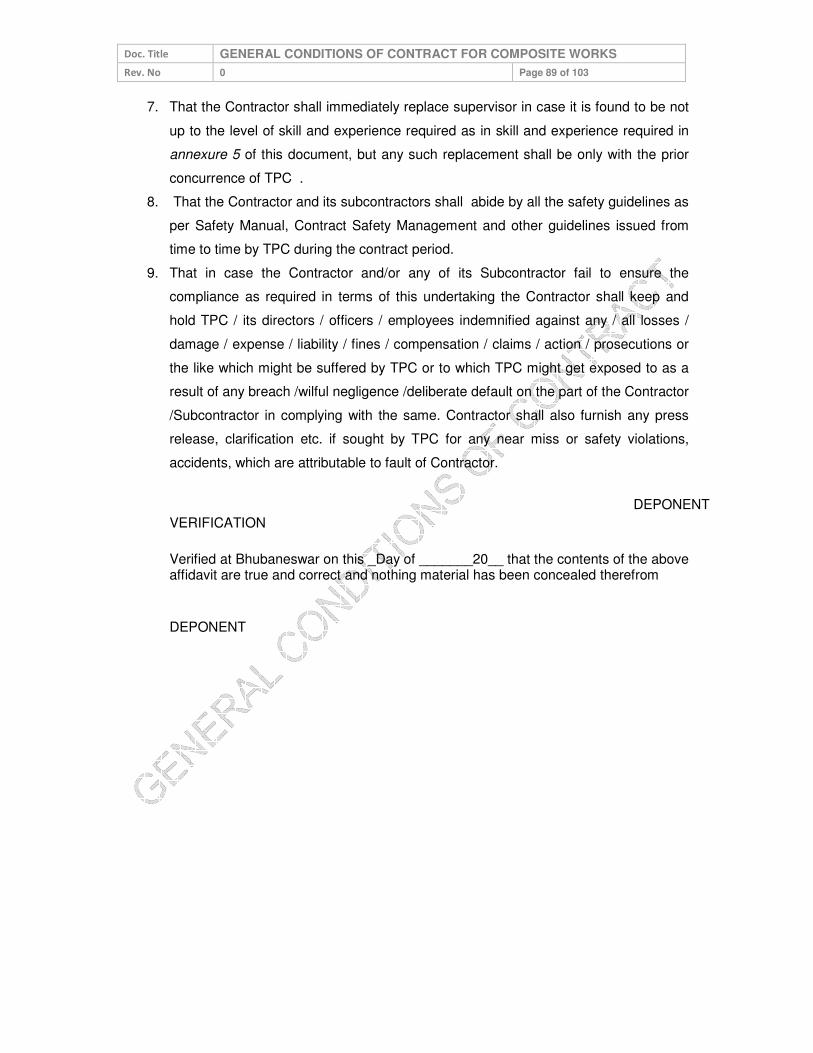
Doc. Title GENERAL CONDITIONS OF CONTRACT FOR COMPOSITE WORKS
Rev. No 0 Page 89 of 103
7. That the Contractor shall immediately replace supervisor in case it is found to be not
up to the level of skill and experience required as in skill and experience required in
annexure 5 of this document, but any such replacement shall be only with the prior
concurrence of TPC .
8. That the Contractor and its subcontractors shall abide by all the safety guidelines as
per Safety Manual, Contract Safety Management and other guidelines issued from
time to time by TPC during the contract period.
9. That in case the Contractor and/or any of its Subcontractor fail to ensure the
compliance as required in terms of this undertaking the Contractor shall keep and
hold TPC / its directors / officers / employees indemnified against any / all losses /
damage / expense / liability / fines / compensation / claims / action / prosecutions or
the like which might be suffered by TPC or to which TPC might get exposed to as a
result of any breach /wilful negligence /deliberate default on the part of the Contractor
/Subcontractor in complying with the same. Contractor shall also furnish any press
release, clarification etc. if sought by TPC for any near miss or safety violations,
accidents, which are attributable to fault of Contractor.
DEPONENT
VERIFICATION
Verified at Bhubaneswar on this _Day of _______20__ that the contents of the above affidavit are true and correct and nothing material has been concealed therefrom
DEPONENT

Doc. Title GENERAL CONDITIONS OF CONTRACT FOR COMPOSITE WORKS
Rev. No 0 Page 90 of 103
Annexure 5 (Refer Para 5.4)
SKILL / QUALIFICATION REQUIRED FOR ELECTRICIAN AND ELECTRICAL
SUPERVISOR
Skill / Qualifications Required for Electrician (Certificate of Competency Class-II):
1. Formal education in ITI – Wireman/ Electrician trade.
OR
2. Working experience of minimum three years of practical wiring.
OR 3. Have completed three years apprenticeship course through Apprenticeship
Advisor, Govt. of Odisha/ other state Govt. in the trade of Lineman / Wireman /
Electrician.
4. A candidate must have attained the age of Eighteen years.
Skill / Qualifications Required for Electrical Supervisor (Certificate of Competency
Class-I):
1. Have at least five years’ experience of practical wiring after passing the
certificate of competency class-II i.e. electrician.
OR 2. Recognized Degree or Diploma or equivalent qualification in Electrical
Engineering from any Technical institute / College or University recognized by
the Board.
AND Must have completed the training/job in rectifying the common defects in electrical line and power installation for a period of one and three years after passing Degree or Diploma respectively
OR 3. Possessing the valid certificate of certificate of competency class – 1 (Electrical
Supervisor)

Doc. Title GENERAL CONDITIONS OF CONTRACT FOR COMPOSITE WORKS
Rev. No 0 Page 91 of 103
Annexure 6 (Refer Para 5.6)
Training Module for BAs Worker & Supervisor
Training for BA Supervisor Duration – 02 Hrs / Month Methodology: Lecture and Practical Demonstration of Safety Zone Creation
Session: 1
Topic: Electrical Safety Aspects Sub Topics:
1. Learning specifics of HT & LT Network of zone 2. Major type of HT / LT / service lines / street light maintenance works 3. Understanding the need of Safety 4. Understanding the safe process of maintenance :
• Planning of the maintenance job
• Availability of men, material & machine, PPEs, Safety gear and approved PTW
• Briefing of the job by the supervisor of the TPC
• Identification of Risks associated with the maintenance work and planning for controlling measures by TPC supervisor
• Creation of safety zone by TPC supervisor and satisfying that the network is dead – Use of Neon Tester, Shorting Chain and Safety Tagging
• Start of the work – Right person for the right job
• Alert supervision
• Completion of the job – Check points
• Energization of network
• Actions to be taken in case of some accident
Session: 2
Topic: Use of Electrical Testing Equipment
Methodology: Lecture and Practical Demonstration
Sub Topics:
1. Meggar, Hi Pot, Clamp On Meter, Neon Tester, Discharge Rod, Line tester etc.
Session: 3
Topic: Awareness of Electrical Safety Aspects A. Understanding the need of this Training and Safety B. Learning specifics of HT & LT Network C. Major type of work to be carried out in zones D. Switching Operations (Do’s & Don’ts) including Street Light Switching E. Working on Height (practical demo also) F. Understanding the Safe Process of Maintenance / Working:
• Planning of the job
• Availability of men, material & machine, PPEs, Safety gear and approved PTW
• Briefing of the job by the supervisor
• Permit to Work
• Safety Tagging and Lock Out Tag out
Doc. Title GENERAL CONDITIONS OF CONTRACT FOR COMPOSITE WORKS
Rev. No 0 Page 92 of 103
• Identification of Risks associated with the work to be carried out and planning for controlling measures by proper supervision
• Concept of “Safety Zone”
• Identification and use of Neon Tester, Shorting Chain, Clamp On Meter, Hi Pot, Meggar etc.
• Completion of the job – Check points
• Accident Theory & Incident Reporting
• Actions to be taken in case of some accident
Session: 4
Topic: Identification, Demonstration and Usages of Tools, PPEs and other Safety
Gears and demonstration of working on HT pole
Session: 5
Topic: Practical demonstration of Safety Zone creation
FREQUENCY
Regular Safety Training Program
• It will be conducted for all field & supervisor staff of BA in such a manner that all BA Personnel attend at least two hours safety training during every month.
One Day Induction Safety Training Programs:
• This training will be for the new BA’s personnel, who have been cleared by the Cross Functional Panel to undergo Safety training and who are likely to be deployed at various work sites of TPC by the BA, as a part of AMC / Work Contract.
Duration / Periodicity:
• Duration and periodicity has been defined above. However, this is subject to change at the discretion of TPC.

Doc. Title GENERAL CONDITIONS OF CONTRACT FOR COMPOSITE WORKS
Rev. No 0 Page 93 of 103
Annexure 7 (Refer Para 5.7)
LIST OF PERSONAL PROTECTIVE EQUIPMENT AND TESTING FREQUENCY
Sl.
No. Name of PPE
IS / EN
Standard Testing Frequency Remarks
Ref Brand &
Model
01
Leather Safety
Shoes (Color –
Black) with PU toe
cap.
IS:15298
(Part-2)
Monthly and visual
check every day for any
crack or damage in the
leather or sole.
BATA (Model
No.- Endura L/C)
Liberty (Model
No. – 7198-01
HT Barton Black
– Warrior)
02
HDPE Safety
helmet with chin
strap and ratchet
type for
adjustment.
IS:2925-1984
Monthly and visual
check every day for any
crack in shell.
Karam (PN
Safetech )
Joseph Leslie
Accent Industries
Honeywell
03 Full body harness
(Safety belt) EN 361
Monthly and visual
check every day of the
bends and the harness.
Karam (PN
Safetech )
Joseph Leslie
Accent Industries
04 Electrical Safety
Gloves
EN: 60903
CE marked
Weekly and visual
check for any crack and
blow test before every
work.
Manufactured
not beyond 12
months.
Make Sparian /
Sumitech / CATU
supplied with
inner cotton
glove with over
glove of split
leather.
05 Full face visor with
safety helmet
EN: 166 CE marked (Visor)
Monthly and visual
check every day for any
crack in shell.
Clear acrylic
visor attached
with safety
helmet.
Karam (PN
Safetech )
Joseph Leslie
Accent Industries
Honeywell
06
Fire Proof jacket
for chest
protection
Monthly and visual
check every day.
07
Safety Chain for
shorting cum
earthing.
As per TPC
standard
Weekly and visual
check before every
work.
Made of brass,
Total length –
5.5 meters and
made of 12
SWG.
Note:

Doc. Title GENERAL CONDITIONS OF CONTRACT FOR COMPOSITE WORKS
Rev. No 0 Page 94 of 103
1. Any other Personal Protection Equipment required beyond above list will be
according to BIS or EN Standards.
2. All Personal Protection Equipment will be checked by the engineer in-charge or
SHE&DM group of TPC.
3. Safety Representative of the BA has to maintain the record of the availability,
condition and checking of the PPEs.
4. All tools required as per the contract must be according to respective IS / EN
standards.
5. TPC may revise or add the above list of PPE and their specifications as and when
feel necessary. The information about new specifications /models will be circulated
by the Engineer In-charge (EIC), which shall adhere by the business associated in
the shortest possible time. The EIC shall issue a memo / instruction to BA with
timeline for implementation. Any delay will be treated as non- compliance / safety
violations. Refer picture of each PPE given in next page.
Pictures of PPE for reference purpose.
Sl.
No. Name of PPE
IS / EN
Standard Picture
01
Leather Safety
Shoes (Color –
Black) with PU
toe cap.
IS:15298(Part-
2) and with test
report of
electrical
resistance.
02
HDPE Safety
helmet with chin
strap and ratchet
type for
adjustment.
IS:2925-1984
03
Full body harness
(Safety belt)
The straps at
shoulder and
thigh shall have
full pad for
comfort. The back
shall be so
designed that
harness straps do
not tangle with
each other.
EN 361:2002
EN 358 : 2000
IS:
3521:1991/2002
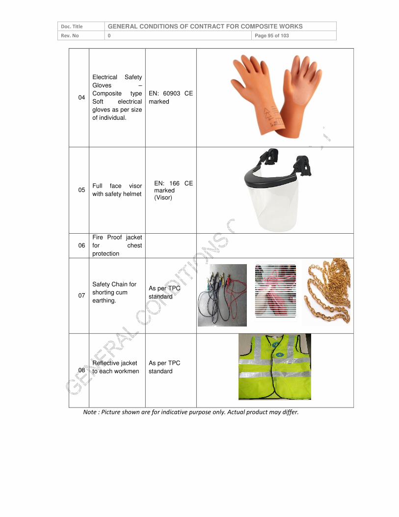
Doc. Title GENERAL CONDITIONS OF CONTRACT FOR COMPOSITE WORKS
Rev. No 0 Page 95 of 103
04
Electrical Safety
Gloves –
Composite type
Soft electrical
gloves as per size
of individual.
EN: 60903 CE
marked
05 Full face visor
with safety helmet
EN: 166 CE marked (Visor)
06
Fire Proof jacket
for chest
protection
07
Safety Chain for
shorting cum
earthing.
As per TPC
standard
08 Reflective jacket
to each workmen
As per TPC
standard
Note : Picture shown are for indicative purpose only. Actual product may differ.

Doc. Title GENERAL CONDITIONS OF CONTRACT FOR COMPOSITE WORKS
Rev. No 0 Page 96 of 103
Annexure 8 (Refer Para 5.8) LIST OF AUDITS TO BE CONDUCTED
Note:
1. (BA Safety Representative has to use the formats as per Safety process COR –
P – 12 of TPC)
Audits Responsibility Freq. Ref. Doc.
Permit to Work & Field Audit
BA Safety Representative
Weekly F04 (COR P -
12)
Tool Bag & PPE’s Audit Weekly F06 (COR P -
12)
First Aid Box Maintenance Record
Fortnightly F08 (COR P -
12)
Fire Extinguisher Record
(Applicable for the BA involved in major
construction works and have storage of flammable
material at worksite)
Monthly F09 (COR P -
12)
Safety Talk Register Weekly F18 (COR P -
12)
Site Safety Audit Daily F29A (COR P -
12)

Doc. Title GENERAL CONDITIONS OF CONTRACT FOR COMPOSITE WORKS
Rev. No 0 Page 97 of 103
Annexure 9 (Refer Para 5.9)
PERFORMANCE REPORT – SAFETY
FOR THE MONTH OF…………………
Name of BA : ………………………………………………………………………………………......
Name of the Project and Purchase order No: ………………………………………………………
Date of commencement of work: …………………………………………………………………….
Man Hour Worked in this month (No. of employees X 8 Hrs + Overtime): ……………………
Cumulative Man Hour worked: ………………………………………………………………………
Total Number of Minor Injury (this month): ………… Minor Injury (Total) ………………….
Major Injury (this month): ……….. Major Injury (Total): ……………
Detail of the Incident / Sub Standard Acts and Condition
Activity This
Month
Cumulative
(Total)
Day Lost (this
month)
Days Lost
(Cumulative)
No. of the Incident
No. of lost time injuries
No. of dangerous
occurrences
No. of near miss reported
Substandard Act/Conditions
observed
Attach details of observation
of this month
Safety Violation Notice
received (from TPC) (both in
numbers and in Rs.)
No. No. No. of violation letter received
and compliance report for the
TPC. Rs. Rs.
Note: Cumulative means total from date of commencement of work according to the
contract.
Detail of the Accident / Near Miss Incidents:
Date and
Time
Type of the
incident
Name of
Employee
Brief
Description
Corrective and
Preventive actions
recommended
Details of the Safety Violations:
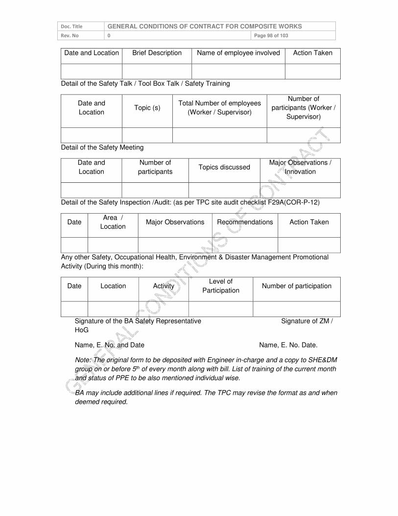
Doc. Title GENERAL CONDITIONS OF CONTRACT FOR COMPOSITE WORKS
Rev. No 0 Page 98 of 103
Date and Location Brief Description Name of employee involved Action Taken
Detail of the Safety Talk / Tool Box Talk / Safety Training
Date and
Location Topic (s)
Total Number of employees
(Worker / Supervisor)
Number of
participants (Worker /
Supervisor)
Detail of the Safety Meeting
Date and
Location
Number of
participants Topics discussed
Major Observations /
Innovation
Detail of the Safety Inspection /Audit: (as per TPC site audit checklist F29A(COR-P-12)
Date Area /
Location Major Observations Recommendations Action Taken
Any other Safety, Occupational Health, Environment & Disaster Management Promotional
Activity (During this month):
Date Location Activity Level of
Participation Number of participation
Signature of the BA Safety Representative Signature of ZM /
HoG
Name, E. No. and Date Name, E. No. Date.
Note: The original form to be deposited with Engineer in-charge and a copy to SHE&DM
group on or before 5th of every month along with bill. List of training of the current month
and status of PPE to be also mentioned individual wise.
BA may include additional lines if required. The TPC may revise the format as and when
deemed required.

Doc. Title GENERAL CONDITIONS OF CONTRACT FOR COMPOSITE WORKS
Rev. No 0 Page 99 of 103
ANNEXURE-M
VENDOR APPRAISAL FORM
TO BE SUBMITTED BY VENDOR (To be filled as applicable)
VENDOR:
1.0 DETAILS OF THE FIRM
1.1 NAME (IN CAPITAL LETTERS) :
1.2 TYPE OF CONCERN (PROPRIETORY) Partnership, Pvt. Ltd., Public Ltd. etc.
:
1.3 YEAR OF ESTABLISHMENT :
1.4
LOCATION OF OFFICE POSTAL ADRESS TELEGRAPHIC ADDRESSES, TELEX NO. FAX NO.
:
1.5 LOCATION OF MANUFACTURING UNITS :
i) UNITS 1 :
ii) OTHER UNITS :
2.0 PRODUCTS MANUFACTURED :
3.0 TURNOVER DURING THE LAST 3 YEARS (TO BE VERIFIED WITH THE LATEST PROFIT & LOSS STATEMENT).
:
4.0 VALUE OF FIXED ASSETS :
5.0 NAME & ADDRESS OF THE BANKERS :
6.0 BANK GUARANTEE LIMIT :
7.0 CREDIT LIMIT :
8.0 TECHNICAL
8.1 NO.OF DESIGN ENGINEERS (INDICATE NO.OF YEARS EXPERIENCE IN RELATED FIELDS)
:
8.2 NO.OF DRAUGHTSMEN :
8.3 COLLABORATION DETAILS (IF ANY) :
8.3.1 DATE OF COLLABORATION :
8.3.2 NAME OF COLLABORATOR :
Doc. Title GENERAL CONDITIONS OF CONTRACT FOR COMPOSITE WORKS
Rev. No 0 Page 100 of 103
8.3.3 RBI APPROVAL DETAILS :
8.3.4 EXPERIENCE LIST OF
COLLABORATOR :
8.3.5 DURATION OF AGREEMENT :
8.4
AVAILABILITY OF STANDARDS / DESIGN PROCEDURES / COLLABORA-TOR’S / DOCUMENTS (CHECK WHETHER THESE ARE LATEST/CURRENT
:
8.5
TECHNICAL SUPPORT, BACK-UP GUARANTEE, SUPERVISION, QUALITY CONTROL BY COLLABORATOR (WHEREVER ESSENTIAL). (THIS CLAUSE IS RELEVANT WHEN VENDOR’S EXPERIENCE IS INADEQUATE)
:
8.6 QUALITY OF DRAWINGS :
9.0 MANUFACTURE
9.1 SHOP SPACE, LAYOUT LIGHTING, VENTILATION, ETC.
:
9.2 POWER (KVA) :
MAINS INSTALLED :
UTILISED :
STANDBY POWER SOURCE :
9.3 MANUFACTURING FACILITIES (ATTACH LIST OF EQUIPMENT AS APPLICABLE)
:
9.3.1 MATERIAL HANDLING :
9.3.2 MACHINING :
9.3.3 FABRICATION :
9.3.4 HEAT TREATMENT :
9.3.5 BALANCING FACILITY :
9.3.6 SURFACE TREATMENT PRIOR TO PAINTING/ COATING, POLISHING, PICKLING, PASSIVATION, PAINTING, ETC.
:
9.4 SUPERVISORY STAFF :
9.5 ADEQUACY OF SKILLED LABOURS (MACHINISTS, WELDERS, ETC.)
:
9.6 NO. OF SHIFTS :
9.7 TYPE OF MATERIAL HANDLED (SUCH AS CS, SS, ETC.)

Doc. Title GENERAL CONDITIONS OF CONTRACT FOR COMPOSITE WORKS
Rev. No 0 Page 101 of 103
9.8 WORKMANSHIP :
9.9 MATERIAL IN STOCK AND VALUE :
9.10 TRANSPORT FACILITIES :
9.11 CARE IN HANDLING :
10.0 INSPECTION / QC / QA / TESTING
10.1 NUMBER OF PERSONNEL (INDICATE NO.OF YEARS OF EXPERIENCE)
:
10.2 INDEPENDENCE FROM PRODUCTION :
10.3 AVAILABILITY OF PROCEDURAL WRITE UP/QUALITY PLAN
:
10.4 INCOMING MATERIAL CONTROL AND DOCUMENTATION
:
10.5 RELIABILITY/REPUTATION OF SUPPLY SOURCES
:
10.6 STAGE INSPECTION AND DOCUMENTATION :
10.7 SUB-ASSEMBLY & DOCUMENTATION :
10.8 FINAL INSPECTION AND DOCUMENTATION :
10.9 PREPARATION OF FINAL DOCUMENTATION PACKAGE
:
10.10 TYPE TEST FACILITIES :
10.11 ACCEPTANCE TEST FACILITIES :
10.12 CALIBRATION OF INSTRUMENTS AND GAUGES (WITH TRACEABILITY TO NATIONAL STANDARDS) (ATTACH LIST)
:
10.13 STATUTORY APPROVALS LIKE BIS, IBR, ETC.(AS APPLICABLE)
:
10.14 SUB-VENDOR APPROVAL SYSTEM AND QUALITY CONTROL
:
10.15 DETAILS OF TESTS CARRIED OUT AT INDEPENDENT RECOGNISED LABORATORIES
:
i) FURNISH LIST OF TESTS CARRIED OUT AND THE NAME OF THE LABORATORY WHERE THE TESTS WERE CONDUCTED
:
ii) CHECK AVAILABILITY OF
CERTIFICATES AND REVIEW THESE WHEREVER POSSIBLE
:
11.0 EXPERIENCE (INCLUDING CONSTRUCTION / ERECTION / COMMISSIONING) TO BE FURNISHED IN THE FORMAT INDICATED IN APPENDIX)
:
12.0 SALES, SERVICE AND SITE ORANISATIONAL DETAILS :
Doc. Title GENERAL CONDITIONS OF CONTRACT FOR COMPOSITE WORKS
Rev. No 0 Page 102 of 103
13.0 CERTIFICATE FROM CUSTOMERS (ATTACH COPIES OF DOCUMENTS)
:
14.0 POWER SITUATION :
15.0 LABOUR SITUATION :
16.0 * APPLICABILITY OF SC/ST RELAXATION (Y/N) IF YES, SUPPORTING DOCUMENTS TO BE ATTACHED
17.0
ORGANIZATIONAL DETAILS 1. PF NO 2. ESI NO 3. INSURANCE FOR WORK MAN COMPENSATION
ACT NO 4. ELECTRICAL CONTRACT LIC NO 5. ITCC / PAN NO 6. SALES TAX NO 7. WC TAX REG. NO
:
18.0
DOCUMENTS TO BE ENCLOSED: 1. FACTORY LICENSE 2. ANNUAL REPORT FOR LAST THREE YEARS 3. TYPE TEST REPORT FOR THE ITEM 4. PAST EXPERIENCE REPORTS 5. ISO CERTIFICATE –QMS, EMS, OHAS, SA 6. REGISTRATION OF SALES TAX 7. COPY OF TIN NO. 8. COPY OF SERVICE TAX NO. 9. REGISTRATION OF CENTRAL EXCISE 10. COPY OF INCOME TAX CLEARANCE. 11. COPY OF PF REGISTRATION 12. COPY OF ESI REGISTRATION 13. COPY OF INSURANCE FOR WORK MAN
COMPENSATION ACT NO 14. COPY OF ELECTRICAL CONTRACT LIC NO 15. COPY OF PAN NO 16. COPY OF WC TAX REGISTRATION 17. DOCUMENTS IN SUPPORT OF SC/ST
RELAXATION AT S.NO.16.0 18. GST Registration No
* Classification of BA s under SC/ST shall be governed under following guidelines:
Proprietorship/ Single Ownership Firm: Proprietor of the firm should be from SC/ST community. Governing document shall be Proprietorship Deed.
Partnership Firm: Only such firms shall qualify which have SC/ST partners holding equal to or more than 50% of the total ownership pattern of the firm. Governing document shall be Partnership Deed.
Private Limited Company: Only such firms shall qualify which have SC/ST directors holding equal to or more than 50% of the total ownership pattern of the firm. Governing document shall be Memorandum of Understanding (MoU) and/or Article of Association (AoA).
NOTE: Certification from SC/ST Commission shall be required for deciding upon SC/ST status of a person.

Doc. Title GENERAL CONDITIONS OF CONTRACT FOR COMPOSITE WORKS
Rev. No 0 Page 103 of 103
ANNEXURE-N
MANUFACTURER AUTHORIZATION FORM
(To be submitted on OEM’s Letter Head)
Date: …………….
Tender Enquiry No.: …………..
To,
Chief (Procurement & Stores)
The Tata Power Company Limited, Mumbai
Sir,
WHEREAS M/s. [name of OEM], who are official manufacturers of ………… having factories at [address of OEM] do hereby authorize M/s [name of bidder] to submit a Bid in relation to the Invitation for Bids indicated above, the purpose of which is to provide the following Goods, manufactured by us
………………………………………………………………………………………………………….
and to subsequently negotiate and sign the Contract.
We hereby extend our full guarantee and warranty in accordance with the Special Conditions of Contract or as mentioned elsewhere in the Tender Document, with respect to the Goods offered by the above firm in reply to this Invitation for Bids.
We hereby confirm that in case, the channel partner fails to provide the necessary services as per the Tender Document referred above, M/s [name of OEM] shall provide standard warranty on the materials supplied against the contract. The warranty period and inclusion / exclusion of parts in the warranty shall remain same as defined in the contract issued to their channel partner against this tender enquiry.
Yours Sincerely,
For ……………..
Authorized Signatory

SUPPLIER REFERENCE MANUAL

CONFIDENTIAL 1
SUPPLIER MANUAL ANSWERING
TO
E-BIDDING & E-AUCTION
Version 1.1
Company Confidential DEC - 2016

CONFIDENTIAL 2
INDEX
1 ACCESSING ARIBA SOURCING ........................................................................................................................ 3
2 VENDOR SCREEN...................................................................................................................................................4
3 SUBMITTING YOUR ANSWERS / PROPOSAL................................................................................................ 4
3.1.1 Review and Approve “Prerequisites” ..................................................................................................................6
3.1.2 Select Items or Lots ..............................................................................................................................................6
3.1.3 Entering Your Prebid ..........................................................................................................................................7
3.1.4 Entering Your Prebid for e-auction.....................................................................................................................8
3.1.5 Participate to the e-auction ................................................................................................................................9
3.1.5.1 How to submit a price...........................................................................................................................................................9
3.1.5.2 What to do If you have a problem during the e-auction? ...................................................................................................10
4 COMMUNICATING WITH UPM NEGOTIATOR..........................................................................................10
5 SUPPLIER FREQUENTLY ASKED QUESTION ...........................................................................................11

CONFIDENTIAL 3
1- Accessing Ariba Sourcing Step 1: You will get an invitation to your email from Ariba System. Keep this email, it contains your login Information and a direct link to Ariba. Step 2: Click “Click Here” to access the Ariba Web Site.
Step 3: Supplier has to click on "Continue"

CONFIDENTIAL 4
Step 4: The registration process only takes a few moments, with a simple one-page registration Define your password and secret question. Click “OK”
Step 5: If it’s the first time you are invited to use UPM Ariba, you’ll need to accept the “Participant Terms”. Select “I accept the terms of this agreement”. Click “Submit”.

CONFIDENTIAL 5
2 Vendor Screen
2.1.1 If vendor goes through mail invitation then directly Screen 3.1.1 will appear, but if If you have used Ariba before and have already accessed an event for the buyer-specific account with your current log in ID, click the Login button to continue. Log in with your Ariba username and password in order to participate in the event OR you have to follow the following steps.
Step 1 - Log on supplier.ariba.com
Step 2 - Put your USER ID and Password in following screen
Step 3 - Go to ARIBA APPS and click on Proposals.

CONFIDENTIAL 6
3 Submitting Your Answers / Proposal 3.1.1 Review and Approve “Prerequisites”
Step 1: Review and download all documents & then Click on “Review Prerequisites”
Step 2: Review and accept “Bidder Agreement”.
3.1.2 Select Items or Lots Step 1: Select Items. - If you do not want to quote for any items/lots then you do not select that lot / items and then go ahead for select and submit lot. Step 2: Click “Submit Select Lots”.

CONFIDENTIAL 7
3.1.3 Entering your offer for RFQ
Step 1: as per following screen Vendor Dashboard will appear where RFQ from TATA Power will be visible.
Step 2 - Follow all the steps of 3.1.1 to 3.1.3 Step 3 - Vendor has to submit their techno commercial offer in 2.1. In this field Do No attach any price content. For Price Bid put all the unit price and taxes and duties in provided field. Put "0" (ZERO) in not applicable field.
Step 4 - After successfully putting Techno commercial offer and price part then click on "Submit Entire Response"
CONFIDENTIAL 8
3.1.4 Entering Your Prebid for e-auction Before participation to the e-auction you must place a pre-bid. If you haven’t placed a Prebid in the Prebid time you won’t be able to participate to the auction itself. Step 1: Populate Your Answers. Step 2: Click “Submit Entire Response”.
When the Prebid time is still open you can still modify your Prebid:
Click on “revise Prebid” and repeat in step 1 and step 2.

CONFIDENTIAL 9
3.1.5 Participate to the e-auction
If you have placed a bid in the Prebid time you will be able to participate to the e-action. E-auctions are rather sort in time (usually less than 20 min per item). Once the time is closed you won’t be able to bid anymore.
When you want to submit your price presses “submit current lot” In case the new price you submit is lower by 10% of the starting price (Prebid Price) the following warning Message will be displayed. To submit the new price, check the box and press submit. If you made a mistake press cancel so that you Mistake would not be submitted.

CONFIDENTIAL 10
3.1.5.2 What to do if you have a problem during the e-auction?
If you have any problem related the system: - Call first Tata Power e- Bidding / Auction Cell
� e- Bidding /Auction Cell details:-
4 Communicating with Tata Power Buyer & Auction team during auction
/ e- bidding Step 1: Click “Compose Message”.
Step 2: Compose Your Message and click “Send”.
Core team
Contact Person E-Mail Id Contact Details
Ravi Shingare [email protected] 9029004168
Himanshu Ranjan [email protected] 9820339961
Escalation Matrix
Paresh Bhatt [email protected]
C T Prakash [email protected] 9223545185

CONFIDENTIAL 11
SUPPLIER- FREQUENTLY ASKED QUESTIONS
If I registered on my buyer's Ariba Sourcing site in the past, do I need to register again?
Answer- Yes. Although you have registered on your buyer's Ariba Sourcing site in the past, registering on the Ariba Commerce Cloud is required. The registration process only takes a few moments, with a simple one-page registration. Registering on the Ariba Commerce Cloud gives you access to all your buyer relationships with one username and password.
What is the Ariba Commerce Cloud?
Answer: - The Ariba Commerce Cloud is your entry point to all of your seller solutions. Rather than managing log in information for multiple buyers' sites, you will have one log in and one account. This means fewer passwords to remember, easier user maintenance for your company, and a unified profile for your organization.
Do I need to add Product and Service Categories during registration?
Answer:-Yes; this is a required field. Product and Service Categories classify what your company sells, and the system uses this information to match potential business opportunities with your products and services. Click Add Product and Service Categories to select one or more categories from the list of options. During registration, you only need to choose one category, preferably related to the event you are joining. You can add, refine, or remove categories any time after the registration process.
Do I need to add ship-to or service locations during registration?
Answer: - Yes; this is a required field. Ship-to or Service locations inform buyers where your company sells its products or provides its services, and the system uses this information to match potential business opportunities with your products and services. Click Add Ship-to or Service Locations to select one or more sales territories from a list. You
can add, refine, or remove ship-to or service locations any time after the registration process.
Do I need to enter a D-U-N-S number when I register?
Answer: - No; this is an optional field. You are only required to complete the fields marked with an asterisk (*). If you enter a D-U-N-S number, and you get a message that the value is already in use, leave the field blank, as D-U-N-S numbers must be unique within the Ariba Commerce Cloud. Your company can have multiple Ariba accounts, but only one account can use the D-U-N-S number. Additional Information: - D-U-N-S is a registered trademark of Dun & Bradstreet or its subsidiaries in the United States and other countries.
Do I need to enter a Tax ID when I register?
Answer: - No, the Tax ID is an optional field. You are only required to fill in the fields marked with an asterisk (*).
What is the difference between the Email and Username fields in my profile?
Answer: - The Email field represents the email address where you wish to receive email notifications. The Username field is the identifier that you use to access your account. The Username field must be in email format, but you do not have to use a valid email address.

CONFIDENTIAL 12
Note: Leave the This is my username box checked if you want your email address to be the same as your username.
How do I participate in my buyer's event using an email invitation?
Answer: - Use the Click here link in the email notification to access the sourcing event.
While buyers might customize the email content you receive, all email invitations contain a link to access the event.
Depending on your previous experience with Ariba solutions, do one of the following to access the event after you click the link:
• If you are new user, click Continue on the welcome page. You continue to register an Ariba account to link with your buyer and participate in the event.
• If you have used Ariba before and have already accessed an event for the buyer-specific account with your current log in ID, click the Login button to continue. Log in with your Ariba username and password in order to participate in the event.
• If you already have an existing Ariba Network, Ariba Discovery, or Ariba Sourcing supplier account, but you have not accessed any events for the inviting buyer's site, use the Click here if you already have an Ariba Commerce Cloud, Ariba Discovery or Ariba Network account link. After clicking the link, log in with your existing account to move your information to your buyer's site.
Additional Information :- Registering an Ariba account provides you with a consolidated view of all your customer relationships. With this one profile, you can view business opportunities, participate in sourcing events, participate in contract negotiations, and manage orders, catalogs, and invoices.
Why doesn't the link in the email invitation to participate in a sourcing event work?
Answer:-If you cannot click the link, or the link does not open the log in page, highlight and copy the Uniform Resource Locator (URL), and then paste the URL into your web browser.
Can my company have multiple accounts?
Answer:-Your Company can have multiple Ariba accounts, depending on your business needs. For example, if your company has several locations around the world, you might want a separate account for each region.
Most companies choose to have one account with multiple customer relationships, which provides a centralized location to maintain their company profile information and all of their customer relationships.
Additional Information
Consider the following items when deciding whether to have more than one account:
• Administrators: For each account, you can have only one account administrator, but the account administrator can provide access to multiple users. All users from your company have their own Username and Password to access the account.
• DUNS (data universal numbering system) numbers: You can add your company's DUNS number to only one account. If you plan to have multiple accounts, leave the DUNS number blank during registration.

CONFIDENTIAL 13
How do I complete registration if my username already exists?
Answer: - This message means that you already have an Ariba Network, Ariba Discovery, or Ariba Sourcing supplier account registered under username you entered. You can either register ua new account by creating a new username, or access one of the following sites to request a password reset for the registered username:
• Ariba Network (This login page is used for all Ariba Network, Ariba Sourcing, or Ariba Contracts suppliers).
• Ariba Discovery login page
To reset your password, click the Having trouble logging in? Link on the Login page.
Nothing happens when I click Forgot Username and enter my email address
Issue: - Nothing happens when I click the Forgot Username link and enter my email address. Cause: - After you submit your request to retrieve your username, the Ariba Network sends an email notification with usernames that match the email address you submitted. Some possible reasons why you may not receive this username retrieval email notification:
• The email address on your account does not match the email address you entered when submitting the request.
• Your buyer-specific account was deactivated before you could move it to the Ariba Commerce Cloud. Generally, that means you probably have not participated in an event with that buyer for a while.
Solution: - • To ensure you receive this email notification: • Make sure you type the email address configured within your account.
If your buyer-specific account has been deactivated, contact your buyer to determine how to proceed.
Where is my password reset email?
Answer: - After you submit your request for a password reset, Ariba sends instructions to the email address associated with your account. If you didn't receive a password reset email, check the following scenarios to troubleshoot.
The username you entered is in the wrong format, or it isn't associated with the email address you are checking.
• Keep in mind, your username is in the format of a full email address, but it can be associated with any email address you entered previously.
• Your username is also case-sensitive. • To confirm that you are using the correct username and format, return to the Ariba login page,
and click the Having trouble logging in? link (Forgot Username if you're working in Ariba Discovery).
o Choose I forgot my username, and click Continue. o Enter the email address associated with your account, and click Submit. o You will receive an email that lists the exact format of the username associated with
the email you entered.

CONFIDENTIAL 14
You entered the correct username, but you still didn't receive the password reset email notification.
• This can occur if the configured email address is different from the account you are checking. • You might have multiple accounts for your company, so make sure you are attempting to
access the correct account.
Your email configuration or company's security settings might also prevent you from receiving the
password reset email. To find out, check your junk mail folder or email filter settings to verify that
automated emails from Ariba are not blocked from your email account.
Why do I get this message on the SAP Ariba Login page: "The username and password
pair you entered was not found"?
Answer: - You entered an incorrect Username or Password. You might receive this message if you entered a previous Username or Password. Remember that your Username has the format of an email address, and both the Username and Password are case sensitive. Click the Having trouble logging in? Link on the Login page if you don't remember your log in
information.