Cornering Forces and Geometry
16
0 of 4 Conduction 3 Steady State ornering Timothy T. Maxwell Advanced Vehicle Engineering La boratory Texas Tech University 2006
-
Upload
mohamedashrafsayed -
Category
Documents
-
view
215 -
download
0
Transcript of Cornering Forces and Geometry

8/17/2019 Cornering Forces and Geometry
http://slidepdf.com/reader/full/cornering-forces-and-geometry 1/16
0 of 4Conduction 3
Steady State
ornering
Timothy T. Maxwell
Advanced Vehicle Engineering Laboratory
Texas Tech University
2006

8/17/2019 Cornering Forces and Geometry
http://slidepdf.com/reader/full/cornering-forces-and-geometry 2/16
8/17/2019 Cornering Forces and Geometry
http://slidepdf.com/reader/full/cornering-forces-and-geometry 3/16
2Steady State Cornering
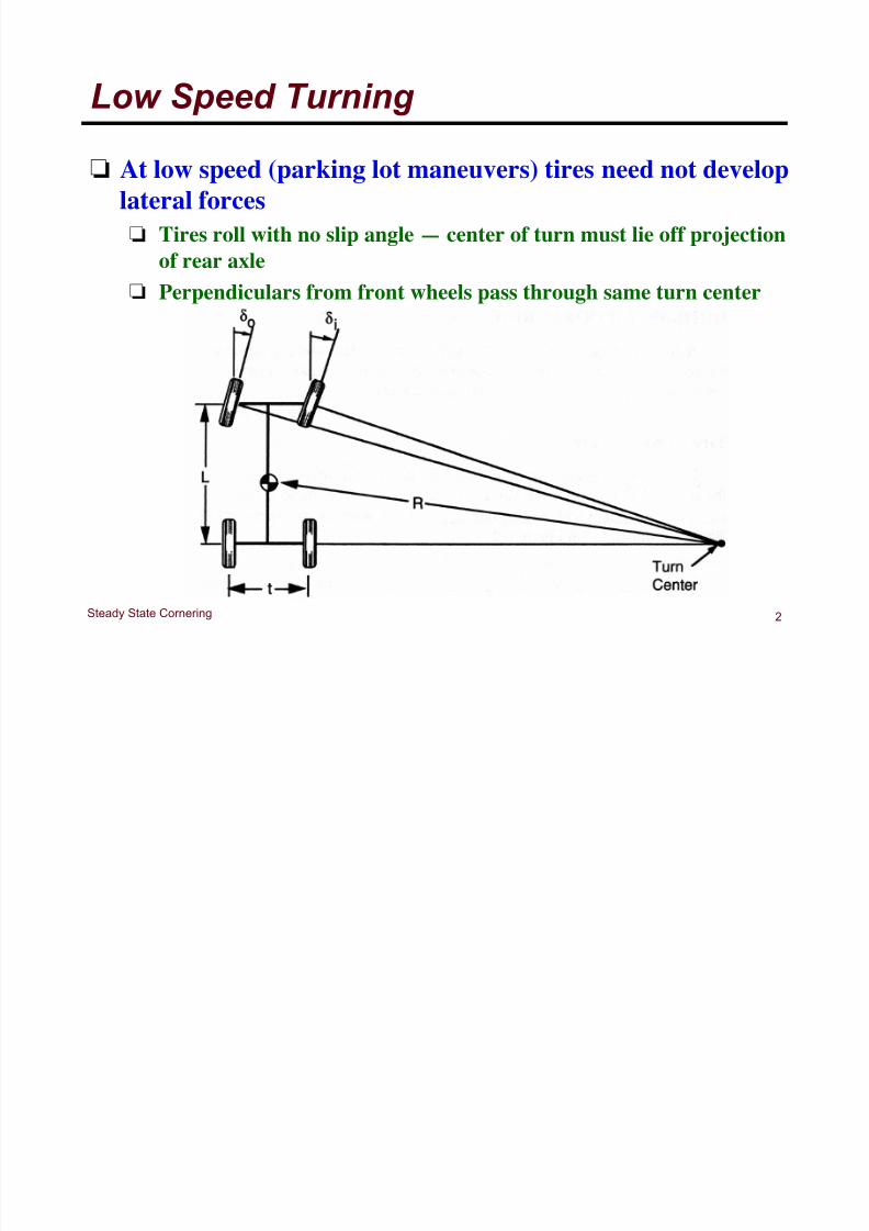
Low Speed Turning
! At low speed (parking lot maneuvers) tires need not developlateral forces
! Tires roll with no slip angle — center of turn must lie off projection
of rear axle
!
Perpendiculars from front wheels pass through same turn center

8/17/2019 Cornering Forces and Geometry
http://slidepdf.com/reader/full/cornering-forces-and-geometry 4/16
3Steady State Cornering
Low Speed Turning
! Ideal turning angles
! Average angle is the
Ackerman Angle
! o =
L
R + t 2( )
! i =
L
R " t 2( )
! ! L
R
8/17/2019 Cornering Forces and Geometry
http://slidepdf.com/reader/full/cornering-forces-and-geometry 5/16
4Steady State Cornering
Ackerman Angle (Low Speed)
! Ackerman angle or Ackerman Geometry
! Exact geometry of front wheels as on previous slide
! Correct angles depend on vehicle wheelbase & turn angle
! Deviations from Ackerman angles for the right or left
steer angles can significantly affect tire wear! Deviations do not significantly affect directional response
for low speed turns
! Deviations do affect steering torques
! With correct Ackerman geometry, steering torques
increase with steer angle and provide feedback to driver
! With parallel steering, steering torque increases initiallyand then decreases! Steering torque can become negative so that vehicle turns more
deeply into turn

8/17/2019 Cornering Forces and Geometry
http://slidepdf.com/reader/full/cornering-forces-and-geometry 6/16
5Steady State Cornering
Off–Tracking at Low Speed
! Off–tracking at rear wheels
! Off–tracking distance
! Recall series form of cos
! Then
!
Off–tracking is primarily a concern for longwheelbase vehicles like trucks and buses
! For articulated vehicle — Tractrix equations
! = R 1" cos L R( )#
$ %
&
cos z = 1! z
2
2!
+ z
4
4!
!
z6
6!
+ z
8
8!
!
! =
L2
2 R

8/17/2019 Cornering Forces and Geometry
http://slidepdf.com/reader/full/cornering-forces-and-geometry 7/16
6Steady State Cornering
High Speed Cornering
! High speed cornering produces different equations
wrt low speed cornering
! Tires must develop significant lateral forces to
counteract the lateral acceleration! Slip angles will be present at each wheel

8/17/2019 Cornering Forces and Geometry
http://slidepdf.com/reader/full/cornering-forces-and-geometry 8/16
7Steady State Cornering
Tire Cornering Forces
! Tire slip–angle between direction of heading and
direction of travel
! Lateral or cornering force grows with slip angle

8/17/2019 Cornering Forces and Geometry
http://slidepdf.com/reader/full/cornering-forces-and-geometry 9/16
8Steady State Cornering
Slip Angles
! Below about5˚ sliprelationshipis linear
! C ! — cornering stiffness
! Positive slip angle produces negative force (to the
left) on tire! Thus, C ! must be negative
! SAE defines C !
as the negative of the slope
F y = C ! !

8/17/2019 Cornering Forces and Geometry
http://slidepdf.com/reader/full/cornering-forces-and-geometry 10/16
9Steady State Cornering
Slip Angle
!Cornering stiffness depends on several variables
!Tire size
Number of plies
!Tire type (radial or bias ply) Cord angles
!Wheel width Load
!Tread design Inflation pressure
! Speed not a strong influence on cornering forces
produced by tire
8/17/2019 Cornering Forces and Geometry
http://slidepdf.com/reader/full/cornering-forces-and-geometry 11/16
10Steady State Cornering
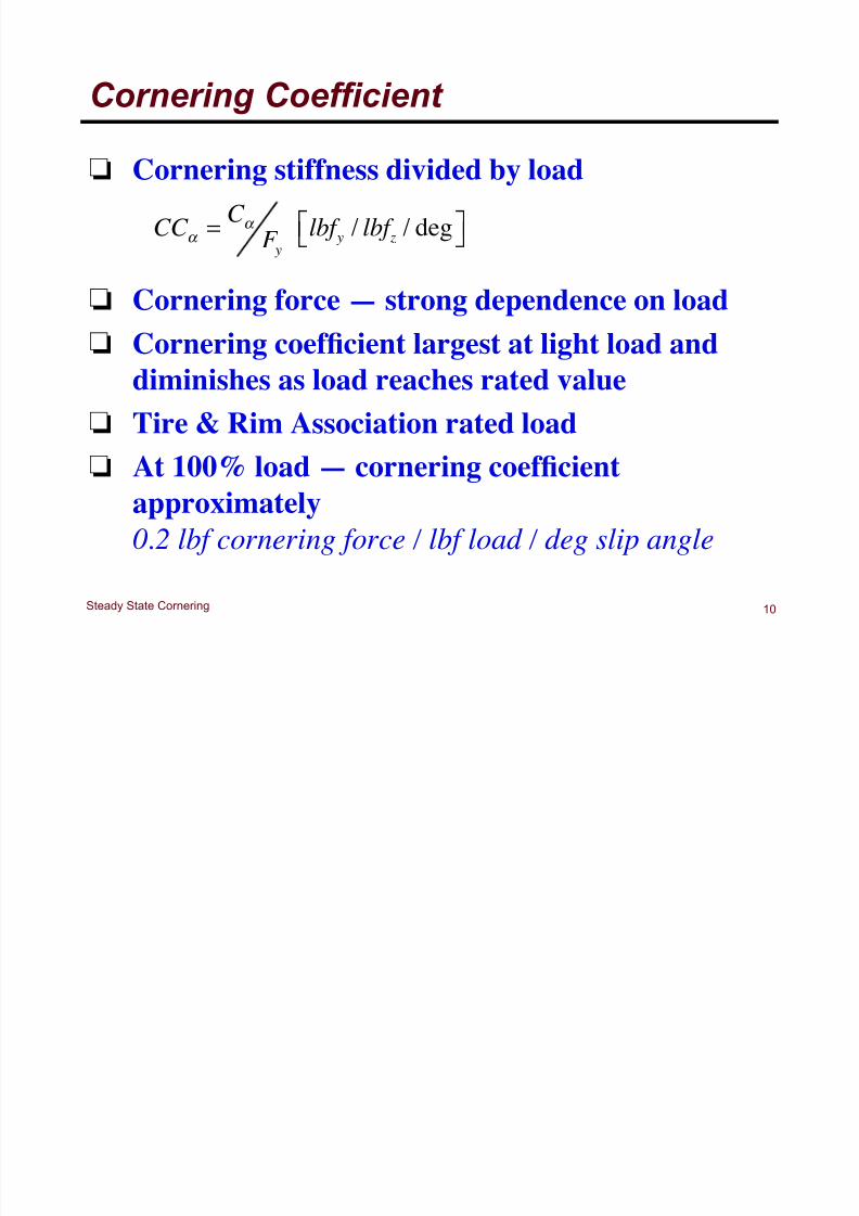
Cornering Coefficient
! Cornering stiffness divided by load
! Cornering force — strong dependence on load! Cornering coefficient largest at light load and
diminishes as load reaches rated value
! Tire & Rim Association rated load
! At 100% load — cornering coefficient
approximately
0.2 lbf cornering force / lbf load / deg slip angle
CC ! =
C !
F ylbf y / lbf z / deg"# $%

8/17/2019 Cornering Forces and Geometry
http://slidepdf.com/reader/full/cornering-forces-and-geometry 12/16
11Steady State Cornering
Slip Angle Dependence
8/17/2019 Cornering Forces and Geometry
http://slidepdf.com/reader/full/cornering-forces-and-geometry 13/16
12Steady State Cornering
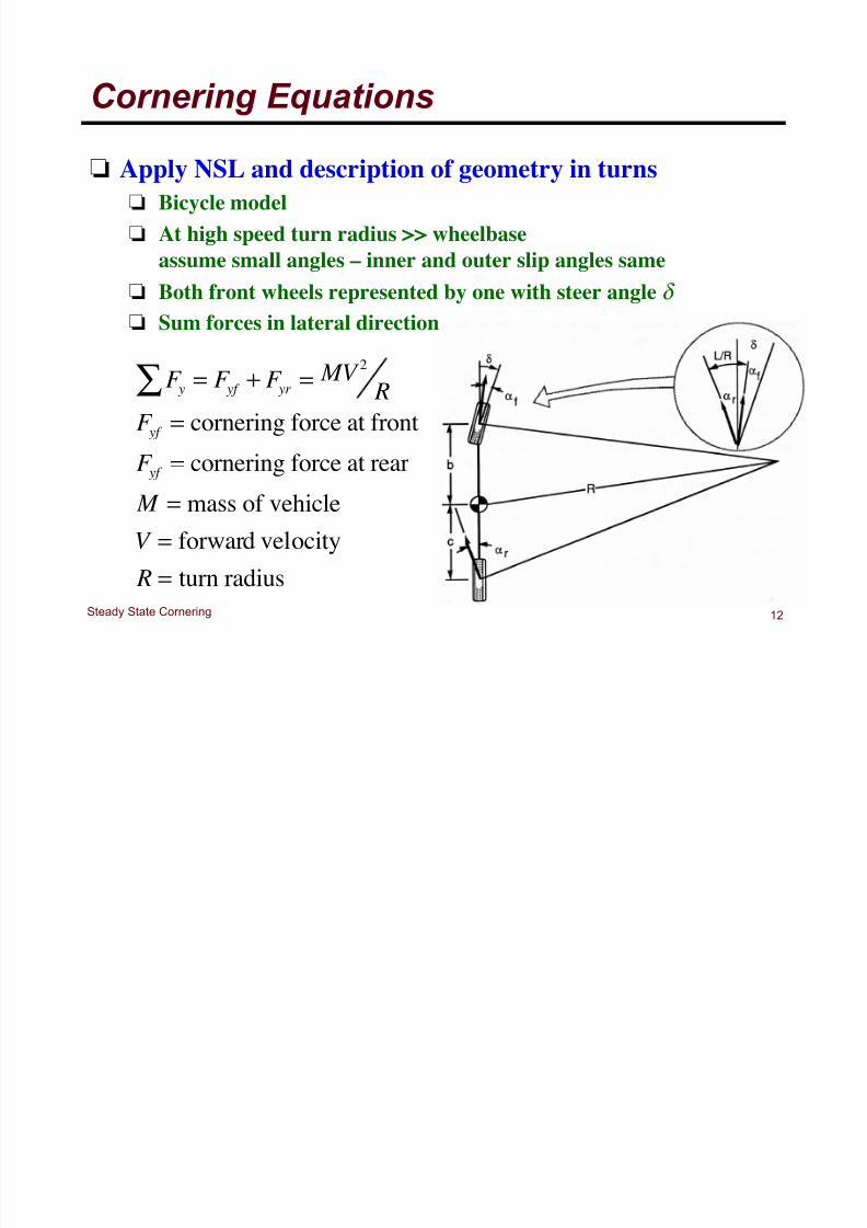
Cornering Equations
! Apply NSL and description of geometry in turns
! Bicycle model
! At high speed turn radius >> wheelbase
assume small angles – inner and outer slip angles same
! Both front wheels represented by one with steer angle "
! Sum forces in lateral direction
F y! = F yf + F yr = MV
2
R
F yf = cornering force at front
F yf = cornering force at rear
M = mass of vehicle
V = forward velocity
R = turn radius
8/17/2019 Cornering Forces and Geometry
http://slidepdf.com/reader/full/cornering-forces-and-geometry 14/16
13Steady State Cornering
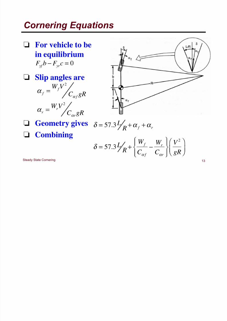
Cornering Equations
! For vehicle to be
in equilibrium
! Slip angles are
! Geometry gives
! Combining
F yf b ! F yrc = 0
! f =
W f V 2
C ! f gR
! r =W rV
2
C ! rgR
! = 57.3 L R
+" f +" r
! = 57.3 L R
+
W f
C " f
# W r
C " r
$%&
'&
()&
*&
V 2
gR
+ , -
. / 0
8/17/2019 Cornering Forces and Geometry
http://slidepdf.com/reader/full/cornering-forces-and-geometry 15/16
14Steady State Cornering
Understeer Gradient
! Previous equation is the Understeer Gradient
! Lateral acceleration
! Magnitude and direction
of steering inputs required
! = 57.3 L R
+ ka y
V 2
gR
W f
C ! f
"
W r
C ! r

8/17/2019 Cornering Forces and Geometry
http://slidepdf.com/reader/full/cornering-forces-and-geometry 16/16
15Steady State Cornering
Understeer Gradient
! Neutral Steer
! Understeer
! Oversteer
W f
C ! f
=
W r
C ! r
" K = 0"! f = ! r
W f
C ! f
>W r
C ! r
"K > 0"! f > ! r
W f
C ! f
<W r
C ! r
"K < 0"! f <! r


![Techniques for aerodynamic analysis of cornering vehicles€¦ · aerodynamic effects experienced during sinusoidal motion [6, 7]. The modified vehicle geometry differed from the](https://static.fdocuments.in/doc/165x107/5f0de72a7e708231d43ca664/techniques-for-aerodynamic-analysis-of-cornering-vehicles-aerodynamic-effects-experienced.jpg)