Copyright © 2000 MIL 3, Inc. Modeling Custom Wireless Effects– 1 OPNET UNIVERSITY 2000...
99
Copyright © 2000 MIL 3, Inc. Modeling Custom Wireless Effects– 1 OPNET UNIVERSITY 2000 Transceiver Pipeline and Radio Modeling
-
Upload
baldric-hines -
Category
Documents
-
view
213 -
download
1
Transcript of Copyright © 2000 MIL 3, Inc. Modeling Custom Wireless Effects– 1 OPNET UNIVERSITY 2000...

Copyright © 2000 MIL 3, Inc. Modeling Custom Wireless Effects– 1
OPNET UNIVERSITY
2000
Transceiver Pipeline and Radio Modeling

Copyright © 2000 MIL 3, Inc. Modeling Custom Wireless Effects– 2
OPNET UNIVERSITY
2000Goals
• Introduce the OPNET Transceiver Pipeline– Capabilities
– Defaults
• Modify pipeline– Show openness and extensibility
– Model custom wireless effects

Copyright © 2000 MIL 3, Inc. Modeling Custom Wireless Effects– 3
OPNET UNIVERSITY
2000Overview
• Wireless modeling overview
• Transceiver pipeline
• Pipeline architecture and default stages– Lab: Closure - Custom Pipeline Statistic
– Break
– Lab: Channel Match - Doppler Shifts
– Break
– Lab: Power, Inoise, ECC - Signal Lock vs. Power Lock
• Conclusion

Copyright © 2000 MIL 3, Inc. Modeling Custom Wireless Effects– 4
OPNET UNIVERSITY
2000Wireless Modeling Overview
• Wireless communications– Broadcast medium
– Communication more likely to be problematic
– Less of a controlled environment than wireline
• Wireless channels need to be characterized appropriately– Model real-world channel behavior
- Frequencies, power, line-of-sight, interference, etc.
– Channel characteristics affect higher layer protocol behavior
• Simulation tool must support wireless modeling– Node mobility
- Car, ship, aircraft, satellite, etc.
– Link-budget-analysis computation

Copyright © 2000 MIL 3, Inc. Modeling Custom Wireless Effects– 5
OPNET UNIVERSITY
2000Transceiver Pipeline
• Models packet transmission across communications channel
• Implements physical layer characteristics
• Divided into multiple stages
• Determines if packet can be received
Tx Rx
S1 S2 S3 S13. . .Each stage models an aspect of the channel’s behavior
Packet

Copyright © 2000 MIL 3, Inc. Modeling Custom Wireless Effects– 6
OPNET UNIVERSITY
2000Pipeline Stages
• Sequence of ‘C’ or ‘C++’ procedures– Computes line-of-sight, signal strength, bit errors, etc.
– Can indicate packet is not receivable
• Each procedure has a defined interface (prototype)– Argument is typically a packet
– Information typically obtained and stored as Transmission Data Attributes (TDA)

Copyright © 2000 MIL 3, Inc. Modeling Custom Wireless Effects– 7
OPNET UNIVERSITY
2000Transmission Data Attributes (TDA)
• Scope– Special packet storage areas
- Part of every packet
– Carry numerical values- Integer, Object ID, floating point, or pointer
– Initialized by kernel at start of transmission– Readable during a packet’s life– Writable only in pipeline
• Purpose– Carry pipeline information
- Kernel to pipeline stage- Pipeline stage to kernel- Between pipeline stages
User-DefinedPre-Defined TDA
Tx Rx

Copyright © 2000 MIL 3, Inc. Modeling Custom Wireless Effects– 8
OPNET UNIVERSITY
2000Pipeline Models
• Scope– Each stage uses a pipeline model– Stages are referenced via a pipeline model object attributes
- Point-to-Point - link attributes- Bus -Bus attributes- Radio - transceiver attributes
– Stages must be compiled prior to reference
• Modeling method– Create stage in context of the pipeline model– Compile stage into object form– Change pipeline model object attribute to reference stage
• NOTE: Stage and procedure (pipeline model context) can be used interchangeably

Copyright © 2000 MIL 3, Inc. Modeling Custom Wireless Effects– 9
OPNET UNIVERSITY
2000Pipeline Model Attributes
• Point-to-point– 4 stages
– Specified as link attributes
• Bus– 6 stages
– Specified as bus attributes
• Radio– 14 stages
– Specified as transceiver attributes

Copyright © 2000 MIL 3, Inc. Modeling Custom Wireless Effects– 10
OPNET UNIVERSITY
2000Default Pipeline Stage Location
• Default stages– <mil3_dir>/<rel_dir>/models/std/links
• Default stage prefixes– dpt_* - default point-to-point– dbu_* - default bus– dra_* - default radio
• NOTE: OPNET can access pipeline stages from any path in mod_dirs

Copyright © 2000 MIL 3, Inc. Modeling Custom Wireless Effects– 11
OPNET UNIVERSITY
2000Pipeline Stage Conventions
• File naming– <name>.ps.c - C procedure– <name>.ps.cpp - C++ procedure– <name>.ps.o - object form
• Procedure naming– Same as file name w/o extension
• Compilation– op_mko -type ps -m <name>– Generates <name>.ps.o
• NOTE: Choices for pipeline stages in OPNET are taken from the set of .ps.o files located in mod_dirs.

Copyright © 2000 MIL 3, Inc. Modeling Custom Wireless Effects– 12
OPNET UNIVERSITY
2000Point-to-Point Pipeline Models
• Execution for one transmission
receiver
transmitter
TransmissionDelay
0
PropagationDelay
1
ErrorAllocation
ErrorCorrection
23

Copyright © 2000 MIL 3, Inc. Modeling Custom Wireless Effects– 13
OPNET UNIVERSITY
2000Bus Pipeline Models
• Execution sequence for one transmission
multiple receivers
transmitter
TransmissionDelay
ClosurePropagation
DelayPropagation
DelayPropagation
DelayClosureClosureClosure
CollisionCollisionCollisionCollision
ErrorAllocation
ErrorAllocation
ErrorAllocation
ErrorAllocation
ErrorCorrection
ErrorCorrection
ErrorCorrection
PropagationDelay
ErrorCorrection
01 2
345
stage 0 executed once per transmission
stages 2 and up are executed separately for each receiver
collision stage may be executed zero or more times

Copyright © 2000 MIL 3, Inc. Modeling Custom Wireless Effects– 14
OPNET UNIVERSITY
2000Radio Pipeline Models
• Execution sequence for one transmission
transmitter
(Continued on the next slide)
ReceiverGroupReceiverGroupReceiverGroupReceiverGroup
TransmissionDelay
LinkClosure
LinkClosure
LinkClosure
LinkClosure
ChannelMatchChannelMatchChannelMatch
Tx AntennaGain
Tx AntennaGain
Tx AntennaGain
Tx AntennaGain
PropagationDelay
PropagationDelay
PropagationDelay
PropagationDelay
ChannelMatch1
2 3
45
0
executed once at the start of simulation for each pair of transmitter and receiver channels
stage 1 executed once per transmission
stages 2-6 executed separately for each receiver

Copyright © 2000 MIL 3, Inc. Modeling Custom Wireless Effects– 15
OPNET UNIVERSITY
2000Radio Pipeline Models (cont.)
• Execution sequence for one transmission (cont.)
multiple receivers
ReceivedPower
BackgroundNoise
InterferenceNoise
Signal-to-NoiseRatio
Bit ErrorRate
ErrorAllocation
ErrorAllocation
ReceivedPowerReceived
PowerRx Antenna
Gain
BackgroundNoise
BackgroundNoiseReceived
Power
InterferenceNoise
InterferenceNoise
Signal-to-NoiseRatio
Signal-to-NoiseRatio
InterferenceNoise
Bit ErrorRate
Bit ErrorRate
Signal-to-NoiseRatio
ErrorAllocation
ErrorAllocation
ErrorAllocation
ErrorAllocation
ErrorAllocation
BackgroundNoise
Bit ErrorRate
6 8 8
91011
12
Stages 9-11 may be executed zero or more times
Stages 10-12 may be executed one or more times
Rx AntennaGain
Rx AntennaGain
Rx AntennaGainError
Correction13

Copyright © 2000 MIL 3, Inc. Modeling Custom Wireless Effects– 16
OPNET UNIVERSITY
2000Radio Pipeline Model Attributes
Radio Transmitter Radio Receiver
8 Stages (6-13) Associated with Radio Receiver
6 Stages (0-5) Associated with Radio Transmitter
•Receiver Group•Transmission Delay•Link Closure•Channel Match•Tx Antenna Gain•Propagation Delay
•Rx Antenna Gain•Received Power•Background Noise•Interference Noise•Signal-to-Noise Ratio•Bit Error Rate•Error Allocation•Error Correction

Copyright © 2000 MIL 3, Inc. Modeling Custom Wireless Effects– 17
OPNET UNIVERSITY
2000Stage 0: Receiver Group
• Invocation– Once at start of simulation
• Purpose– Filter out ineligible receiver channels
- Simulation runtime improvements
– Possible uses- Disjunct frequency bands- Excessive physical separation- Antenna Nulls
• Requirements– Return value of OPC_TRUE or OPC_FALSE
• Results– Defines destination channel set for each transmitting channel
Tx
Rx 0
Rx 1
Rx 2
Rx 3
Rx 0Rx 1Rx 3
Example:

Copyright © 2000 MIL 3, Inc. Modeling Custom Wireless Effects– 18
OPNET UNIVERSITY
2000Stage 0: Receiver Group (default)
• Name– dra_rxgroup
• Computation– None
• Result– All receivers are potential destinations
- Returns OPC_TRUE
Tx
Rx
Rx
RxRx
Default:
Tx
Rx
Rx
RxRx
Custom:

Copyright © 2000 MIL 3, Inc. Modeling Custom Wireless Effects– 19
OPNET UNIVERSITY
2000Stage 1: Transmission Delay
• Invocation– First dynamic stage
– Start of packet transmission
– Single invocation for all destination channels
• Purpose– Computes time required to transmit packet
• Requirements– Sets TX_DELAY TDA
• Results– Kernel schedules end-of-transmission event
- Signals start of transmission of next packet in transmitter queue

Copyright © 2000 MIL 3, Inc. Modeling Custom Wireless Effects– 20
OPNET UNIVERSITY
2000Stage 1: Transmission Delay (default)
• Name– dra_txdel
• Computation– Based on channel data rate and packet length
- Data rate (bits/sec) from TX_DRATE TDA
- Packet length (bits) from op_pk_total_size_get ()
• Result– Places computed delay value in TX_DELAY TDA
TxTx
TimeTx Start Tx End
Tx Delay
Default:
Data Rate
gthPacket LenDelay

Copyright © 2000 MIL 3, Inc. Modeling Custom Wireless Effects– 21
OPNET UNIVERSITY
2000Stage 2: Closure
• Invocation– Once for each destination channel– Called immediately after stage 1 - no intervening events
• Purpose– Determines if signal can reach destination– Allows dynamic enabling/disabling of links
• Requirements– Sets PROP_CLOSURE TDA
• Results– Occlusion (obstruction)
- Packet destroyed by kernel- No further stages are called for packet

Copyright © 2000 MIL 3, Inc. Modeling Custom Wireless Effects– 22
OPNET UNIVERSITY
2000Stage 2: Closure (default)
• Name– dra_closure
• Computation– Based on ray-tracing line of sight model
– Assumes Earth is spherical
– Three occlusion checks- Case 1: 90o
- Case 2: 90o , < 90o
- Case 3: 90o, 90o, d Earth Radius
• Result– If any case fails, occlusion exists
- PROP_CLOSURE set to OPC_FALSE
Tx
Rx
T
> 90
D
R
Case 1:
Case 2:
Case 3:
TxRx
T
< 90
D
R
> 90
d
Tx
Rx
T
< 90
D
R
< 90

Copyright © 2000 MIL 3, Inc. Modeling Custom Wireless Effects– 23
OPNET UNIVERSITY
2000Lab: Link Closure - Overview
• Problem– Higher layer protocols implemented and tested to operate over wireline
– Models were updated to include wireless transceivers
– Results show no traffic received
• Goals– Determine link closure status
- Modify closure stage to record statistic
– Eliminate any occlusions- Use closure stage that guarantees link closure is met
• Purpose– Show how stages can be modified
– Guarantee link closure

Copyright © 2000 MIL 3, Inc. Modeling Custom Wireless Effects– 24
OPNET UNIVERSITY
2000Lab: Link Closure - Project/Scenario
• Start OPNET Modeler (Radio)– Double desktop icon
• Open project– Closure
• View scenario– Zero_Antenna_Height_Failure
- Transmitter
- Receiver
• NOTE: When OPNET is not being used, minimize application
Copyright © 2000 MIL 3, Inc. Modeling Custom Wireless Effects– 25
OPNET UNIVERSITY
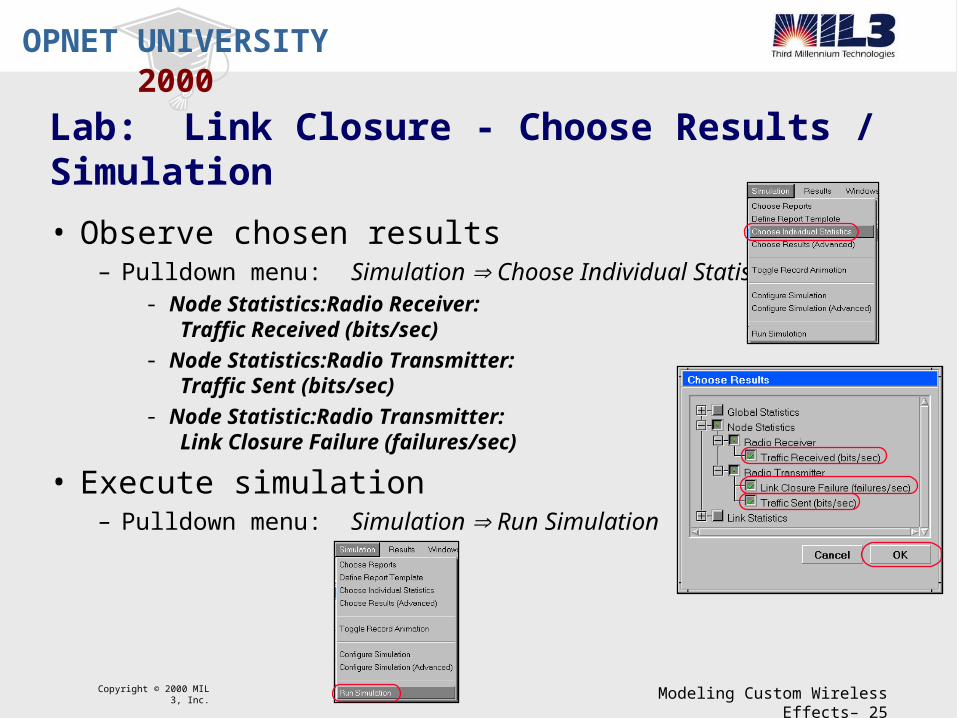
2000Lab: Link Closure - Choose Results / Simulation
• Observe chosen results– Pulldown menu: Simulation Choose Individual Statistics
- Node Statistics:Radio Receiver: Traffic Received (bits/sec)
- Node Statistics:Radio Transmitter: Traffic Sent (bits/sec)
- Node Statistic:Radio Transmitter: Link Closure Failure (failures/sec)
• Execute simulation– Pulldown menu: Simulation Run Simulation

Copyright © 2000 MIL 3, Inc. Modeling Custom Wireless Effects– 26
OPNET UNIVERSITY
2000Lab: Closure - View Results
• View Results– Pulldown menu: Results View Results– Select statistics
- Object Statistics:Closure:Transmitter:Radio Transmitter: Traffic Sent (bits/sec)
- Object Statistics:Closure:Receiver:Radio Receiver: Traffic Received (bits/sec)
• Show results– Click Show
• Conclusion– Traffic is being generated by transmitter– Traffic is not being received by receiver
Copyright © 2000 MIL 3, Inc. Modeling Custom Wireless Effects– 27
OPNET UNIVERSITY
2000Lab: Closure - Stage Modification Overview
• Goal– Modify the link closure stage
– Collect a custom statistic
• Approach– Modify the pipeline stage
- Add code to collect new statistic
– Update Models- Project: Create new scenario
- Node: Update node model
– Execute simulation
– View results

Copyright © 2000 MIL 3, Inc. Modeling Custom Wireless Effects– 28
OPNET UNIVERSITY
2000Lab: Closure - Open Pipeline Stage
• Open pipeline stage– Open Windows NT Explorer
- Double click desktop icon
– Go to directory containing file- c:\users\student\op_models
– Double click to open file- opnetwork_closure_stats.ps.c
– Pipeline stage should open in Microsoft Development Studio

Copyright © 2000 MIL 3, Inc. Modeling Custom Wireless Effects– 29
OPNET UNIVERSITY
2000Lab: Closure - Modify Pipeline Stage
• Modify stage– Observe code block at end of file
- Line 99 through 142
– Cut lines- Line 103: #if 0- Line 142: #endif
– Save file
• NOTE: When Microsoft Development Studio is not being used, minimize application

Copyright © 2000 MIL 3, Inc. Modeling Custom Wireless Effects– 30
OPNET UNIVERSITY
2000Lab: Closure - Compile Pipeline Stage
• Compile the pipeline stage– Open a Command Prompt window
- Double click desktop icon
– Execute the compile command- op_mko -type ps -m opnetwork_closure_stats
• NOTE: When Command Prompt is not being used, minimize application

Copyright © 2000 MIL 3, Inc. Modeling Custom Wireless Effects– 31
OPNET UNIVERSITY
2000Lab: Closure - Duplicate Scenario
• Return to OPNET Modeler (Radio)– Maximize application
• Refresh model directories– Pulldown menu: File Refresh Model Directories
– Required for OPNET to know about new files
• Duplicate scenario– Pulldown menu: Scenarios Duplicate Scenario
– Scenario name: Zero_Antenna_Height_Failure_Stats
Copyright © 2000 MIL 3, Inc. Modeling Custom Wireless Effects– 32
OPNET UNIVERSITY
2000Lab: Closure - Update Node Model
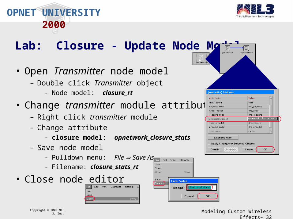
• Open Transmitter node model– Double click Transmitter object
- Node model: closure_rt
• Change transmitter module attribute– Right click transmitter module
– Change attribute- closure model: opnetwork_closure_stats
– Save node model- Pulldown menu: File Save As
- Filename: closure_stats_rt
• Close node editor
Copyright © 2000 MIL 3, Inc. Modeling Custom Wireless Effects– 33
OPNET UNIVERSITY
2000Lab: Closure - Update Network Model
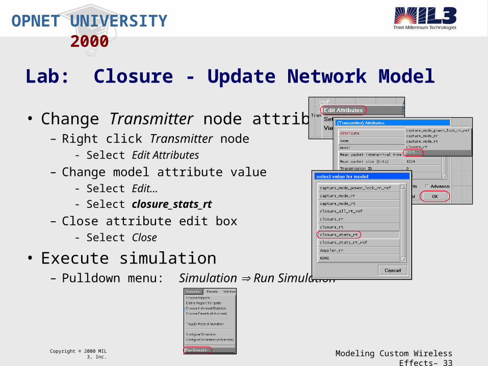
• Change Transmitter node attribute– Right click Transmitter node
- Select Edit Attributes
– Change model attribute value- Select Edit...
- Select closure_stats_rt
– Close attribute edit box- Select Close
• Execute simulation– Pulldown menu: Simulation Run Simulation

Copyright © 2000 MIL 3, Inc. Modeling Custom Wireless Effects– 34
OPNET UNIVERSITY
2000Lab: Closure - View Results
• View Results– Pulldown menu: Results View Results
– Select Statistics- Object Statistics:Closure:Transmitter:Radio Transmitter: Link Closure Failure (failures/sec)
• Show results– Click Show
• Conclusion– Closure is failing, causing undesired packet loss

Copyright © 2000 MIL 3, Inc. Modeling Custom Wireless Effects– 35
OPNET UNIVERSITY
2000Lab: Closure - Stage Modification Overview
• Goal– Modify the link closure model to eliminate closure failure
• Approach– Update Models
- Project: Create new scenario
- Node: Update node model
– Execute simulation
– View results

Copyright © 2000 MIL 3, Inc. Modeling Custom Wireless Effects– 36
OPNET UNIVERSITY
2000Lab: Closure - Duplicate Scenario
• Duplicate scenario– Pulldown menu: Scenarios Duplicate Scenario
- Scenario name: Zero_Antenna_Height_Success

Copyright © 2000 MIL 3, Inc. Modeling Custom Wireless Effects– 37
OPNET UNIVERSITY
2000Lab: Closure - Update Node Model
• Open Transmitter node model– Double click Transmitter object
- Node model: closure_stats_rt
• Change module attribute– Right click transmitter module
– Change attribute- closure model: dra_closure_all
– Save node model- Pulldown menu: File Save As
- Filename: closure_all_rt
• Close node model

Copyright © 2000 MIL 3, Inc. Modeling Custom Wireless Effects– 38
OPNET UNIVERSITY
2000Lab: Closure - Closure All Stage
• Open pipeline stage– Return to Windows NT Explorer
– Go to directory containing file- c:\users\student\op_models
– Double click to open file- dra_closure_all.ps.c
• Closure All– Performs no computation
– Link closure met for all destination channels
– Sets CLOSURE TDA to OPC_TRUE
Copyright © 2000 MIL 3, Inc. Modeling Custom Wireless Effects– 39
OPNET UNIVERSITY
2000Lab: Closure - Update Network Model
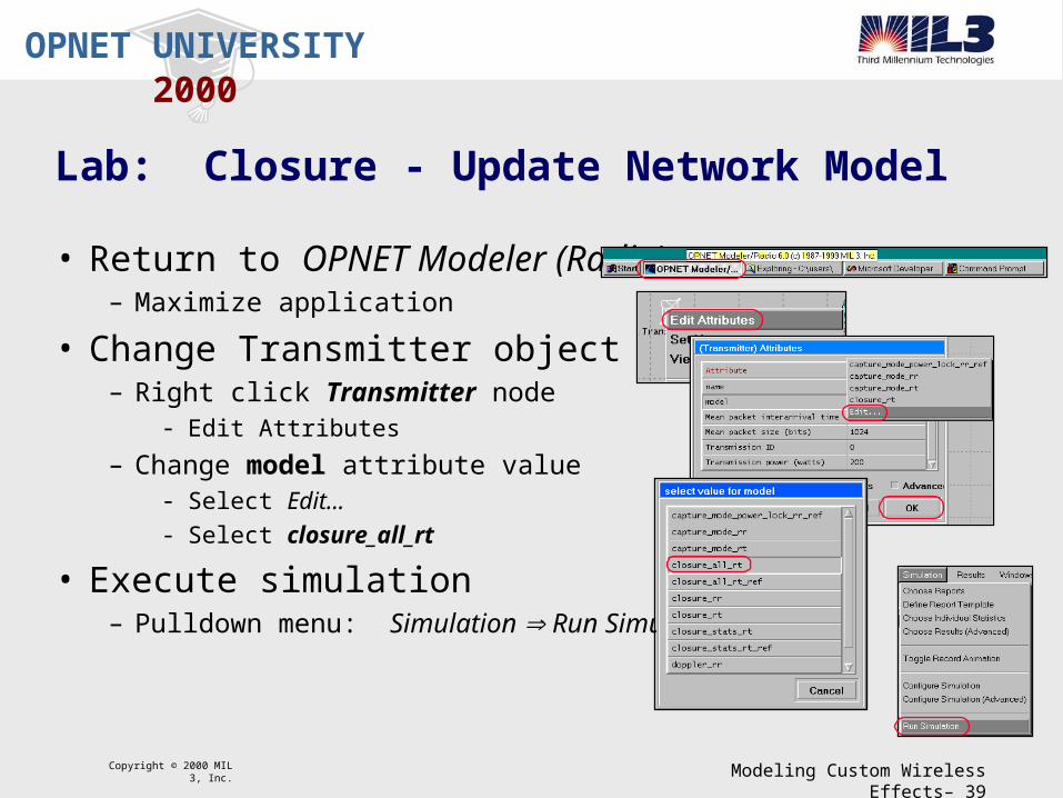
• Return to OPNET Modeler (Radio)– Maximize application
• Change Transmitter object– Right click Transmitter node
- Edit Attributes
– Change model attribute value- Select Edit...
- Select closure_all_rt
• Execute simulation– Pulldown menu: Simulation Run Simulation

Copyright © 2000 MIL 3, Inc. Modeling Custom Wireless Effects– 40
OPNET UNIVERSITY
2000Lab: Closure - View Results
• View Results– Pulldown menu: Results View Results– Select statistics
- Object Statistics:Closure:Transmitter:Radio Transmitter: Traffic Sent (bits/sec)
- Object Statistics:Closure:Receiver:Radio Receiver: Traffic Received (bits/sec)
• Show results– Click Show
• Conclusion– Traffic is being generated by transmitter– Traffic is being received by receiver– Closure was failing due to occlusions

Copyright © 2000 MIL 3, Inc. Modeling Custom Wireless Effects– 41
OPNET UNIVERSITY
2000Lab: Closure - Summary
• Zero antenna height (altitude)– common problem of packet loss
• Pipeline stage modification– Record custom statistic
- Helps assess problem
– Use of dra_closure_all- Eliminates closure computations
- Causes no link failures due to occlusions
• NOTE: Another common problem of packet loss in the pipeline is due to the ECC threshold. The same approach as above can be applied to isolate the problem and counter with a pipeline modification.

Copyright © 2000 MIL 3, Inc. Modeling Custom Wireless Effects– 42
OPNET UNIVERSITY
2000Stage 3: Channel Match
• Invocation– Once for each destination channel satisfying stage 2– Called immediately after stage 2 - no intervening events
• Purpose– Classifies the transmission
- Valid, noise, or ignore- Based on frequency, bandwidth, data rate, spreading code, etc.
• Requirements– Sets MATCH_STATUS TDA
• Results– Kernel destroys ignored packets– If ignore, no further stages are called for packet

Copyright © 2000 MIL 3, Inc. Modeling Custom Wireless Effects– 43
OPNET UNIVERSITY
2000Stage 3: Channel Match (default)
• Name– dra_chanmatch
• Computation– Accounts for frequency overlap, data rate,
modulation, and spreading code
– Three cases- Case 1: No frequency overlap - ignored
- Case 2: Partial characteristic match - noise
- Case 3: Full characteristic match - valid
• Result– Sets MATCH_STATUS TDA based on case
Case 1:
Case 2:
Case 3:
ModTx ModRx
DRTx DRRx
FTx FRx
DRTx DRRx
ModTx ModRx
FTx FRx
FTx FRx

Copyright © 2000 MIL 3, Inc. Modeling Custom Wireless Effects– 44
OPNET UNIVERSITY
2000Stage 4: Transmitter Antenna Gain
• Invocation– Once for each destination channel satisfying stage 2 and stage 3
– Called immediately after stage 3 - no intervening events
• Purpose– Computes transmitter antenna gain in the direction of the receiver
• Requirements– Sets TX_GAIN TDA
• Results– Typically used by stage 7 for receiver power computation
Copyright © 2000 MIL 3, Inc. Modeling Custom Wireless Effects– 45
OPNET UNIVERSITY
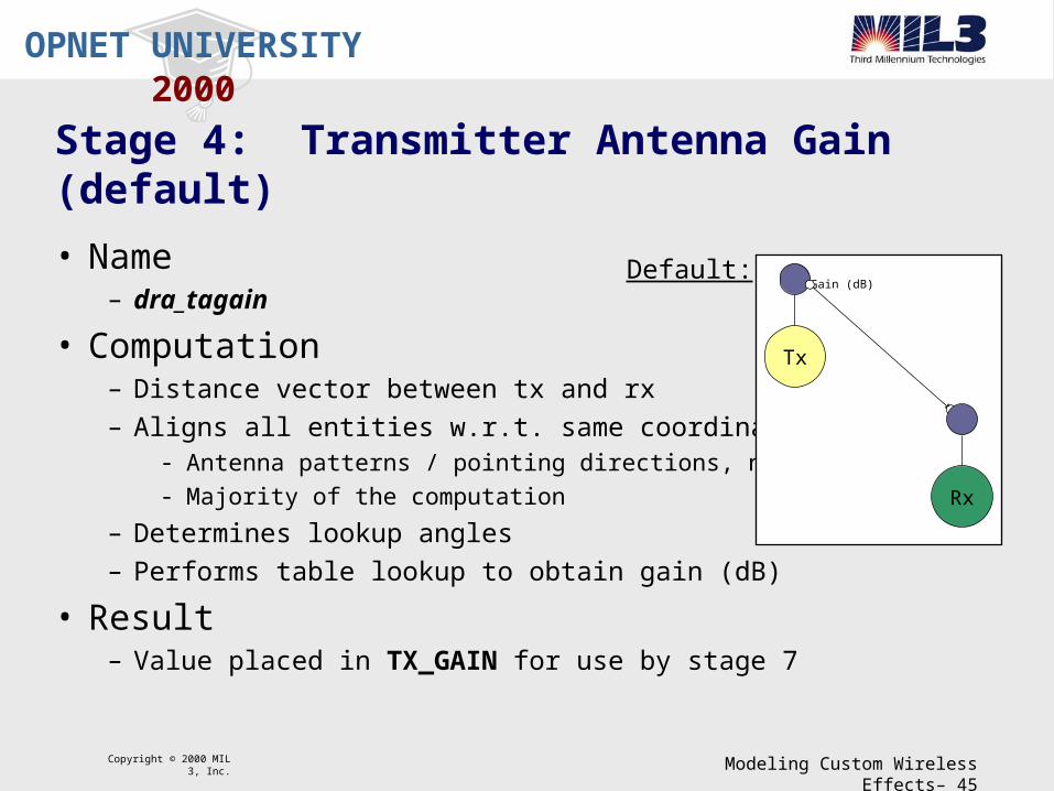
2000Stage 4: Transmitter Antenna Gain (default)
• Name– dra_tagain
• Computation– Distance vector between tx and rx
– Aligns all entities w.r.t. same coordinate system- Antenna patterns / pointing directions, node locations
- Majority of the computation
– Determines lookup angles
– Performs table lookup to obtain gain (dB)
• Result– Value placed in TX_GAIN for use by stage 7
Gain (dB)
Tx
Rx
Default:
Copyright © 2000 MIL 3, Inc. Modeling Custom Wireless Effects– 46
OPNET UNIVERSITY
2000Stage 5: Propagation Delay
• Invocation– Once for each destination channel– Called immediately after stage 4 - no intervening events
• Purpose– Calculates signal propagation time from transmitter to receiver– Usually dependent on distance and propagation velocity
• Requirements– Sets START_PROPDEL and END_PROPDEL TDAs
• Results– Kernel schedules
- Start of reception event- End of reception event

Copyright © 2000 MIL 3, Inc. Modeling Custom Wireless Effects– 47
OPNET UNIVERSITY
2000Stage 5: Propagation Delay (default)
• Name– dra_propdel
• Computation– Based on distance and propagation velocity– Computed for start and end of transmission
- Takes into account mobility
– Obtains distances (in meters)- START_DIST and END_DIST TDAs
• Result– Places computed values in START_PROPDEL and END_PROPDEL TDAs– Kernel schedules start and end reception events
Default:
Rx
TimeRx Start Rx End
Prop Delay
Rx
Velocity
DistanceDelay

Copyright © 2000 MIL 3, Inc. Modeling Custom Wireless Effects– 48
OPNET UNIVERSITY
2000Lab: Doppler Shifts - Overview
• Problem– Doppler shifts - caused by transceiver mobility
– Receiver must handle frequency effects
– Default stages assume no frequency shift
• Goals– Determine appropriate stage location
– Implement Doppler shifting and record frequency shift statistic
• Purpose– Show pipeline stage modifications to account for Doppler shifts
– Show use of external files

Copyright © 2000 MIL 3, Inc. Modeling Custom Wireless Effects– 49
OPNET UNIVERSITY
2000Lab: Doppler - Project/Scenario
• Return to OPNET Modeler (Radio)– Maximize application
• Open project– Doppler
• View scenario– No_Doppler_Shift
- Transmitter - aircraft
- Receiver

Copyright © 2000 MIL 3, Inc. Modeling Custom Wireless Effects– 50
OPNET UNIVERSITY
2000Lab: Doppler - Choose Results / Simulation
• Observe chosen results– Pulldown menu: Simulation Choose Individual Statistics
- Node Statistics:Radio Receiver: Traffic Received (bits/sec)
- Node Statistics:Radio Transmitter: Traffic Sent (bits/sec)
- Node Statistic:Radio Transmitter: Transmission Frequency - Unshifted (Hz)
- Node Statistic:Radio Transmitter: Transmission Frequency - Shifted (Hz)
• Execute simulation– Pulldown menu: Simulation Run Simulation

Copyright © 2000 MIL 3, Inc. Modeling Custom Wireless Effects– 51
OPNET UNIVERSITY
2000Lab: Doppler - View Results
• View Results– Pulldown menu: Results View Results
– Select statistics- Object Statistics:Doppler:Transmitter:Radio Transmitter: Transmission Frequency - Unshifted (Hz)
• Show results– Click Show
• Conclusion– Default behavior observed
– No shift in frequency
– No Doppler shift computations

Copyright © 2000 MIL 3, Inc. Modeling Custom Wireless Effects– 52
OPNET UNIVERSITY
2000Lab: Doppler - Stage Modification Overview
• Goal– Modify the pipeline to compute Doppler shifts
– Record the shifted frequency
• Approach– Find the appropriate pipeline location
– Modify the pipeline stage- Add code to compute Doppler shift
– Update Models- Project: Create new scenario
- Node: Update node model
– Execute simulation
– View results

Copyright © 2000 MIL 3, Inc. Modeling Custom Wireless Effects– 53
OPNET UNIVERSITY
2000Lab: Doppler - Stage Location
• Stage Location dependencies– Requires computed results from previous stages
– Prior to computations in future stages
– Similar computations already exist
• Stage Location Possibilities– Channel match model obtains frequency information
- Results could be used for MATCH_STATUS TDA
– Computations require start and end distance computations- START_DIST and END_DIST TDAs
- Initialized by kernel at start of transmission
• Stage Location– Channel match model

Copyright © 2000 MIL 3, Inc. Modeling Custom Wireless Effects– 54
OPNET UNIVERSITY
2000Lab: Doppler - Open Pipeline Stage
• Open pipeline stage– Return to Windows NT Explorer
– Go to directory containing file- c:\users\student\op_models
– Double click to open file- opnetwork_chanmatch_no_doppler.ps.c

Copyright © 2000 MIL 3, Inc. Modeling Custom Wireless Effects– 55
OPNET UNIVERSITY
2000Lab: Doppler - Modify Pipeline Stage
• Modify stage– Change procedure name and FIN
- Lines 17 and 26- opnetwork_chanmatch_doppler
– Cut lines- Line 45: #if 0- Line 47: #endif
– Save file- opnetwork_chanmatch_doppler
Copyright © 2000 MIL 3, Inc. Modeling Custom Wireless Effects– 56
OPNET UNIVERSITY
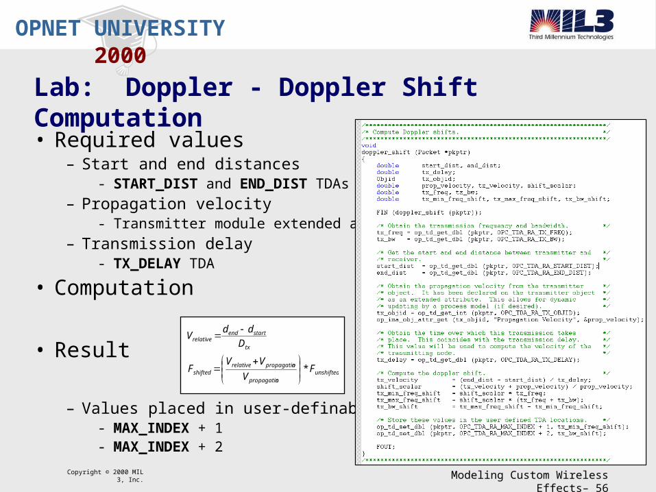
2000Lab: Doppler - Doppler Shift Computation
• Required values– Start and end distances
- START_DIST and END_DIST TDAs
– Propagation velocity- Transmitter module extended attribute
– Transmission delay- TX_DELAY TDA
• Computation
• Result
– Values placed in user-definable TDAs- MAX_INDEX + 1- MAX_INDEX + 2
unshiftednpropagatio
npropagatiorelativeshifted
tx
startendrelative
FV
VVF
D
ddV
*

Copyright © 2000 MIL 3, Inc. Modeling Custom Wireless Effects– 57
OPNET UNIVERSITY
2000Lab: Doppler - Compile Stage / External File
• Compile the pipeline stage– Return to a Command Prompt
– Execute the compile command- op_mko -type ps -m opnetwork_chanmatch_doppler- op_mko -type ex -m doppler_shift

Copyright © 2000 MIL 3, Inc. Modeling Custom Wireless Effects– 58
OPNET UNIVERSITY
2000Lab: Doppler - Duplicate Scenario
• Return to OPNET Modeler (Radio)– Maximize application
• Refresh model directories– Pulldown menu: File Refresh Model Directories
– Required for OPNET to know about new files
• Duplicate scenario– Pulldown menu: Scenarios Duplicate Scenario
– Scenario name: Doppler_Shift
• Include external file– Pulldown menu: File Declare External Files
- Change doppler_shift status to included

Copyright © 2000 MIL 3, Inc. Modeling Custom Wireless Effects– 59
OPNET UNIVERSITY
2000Lab: Doppler - Update Node Model
• Open Transmitter node model– Double click Transmitter object
- Node model: no_doppler_rt
• Change transmitter module attribute– Right click transmitter module
– Change attribute- chanmatch model: opnetwork_chanmatch_doppler
– Save node model- Pulldown menu: File Save As
- Filename: doppler_rt
• Close node model

Copyright © 2000 MIL 3, Inc. Modeling Custom Wireless Effects– 60
OPNET UNIVERSITY
2000Lab: Doppler - Update Network Model
• Return to the Project/Scenario– Doppler-Doppler_Shift
• Change Transmitter node attribute– Right click Transmitter node
- Select Edit Attributes
– Change model attribute value- Select Edit...
- Select doppler_rt
– Close attribute edit box- Select Close
• Execute simulation– Pulldown menu: Simulation Run Simulation

Copyright © 2000 MIL 3, Inc. Modeling Custom Wireless Effects– 61
OPNET UNIVERSITY
2000Lab: Doppler - View Results
• View Results– Pulldown menu: Results View Results– Select Statistics
- Object Statistics:Doppler:Transmitter:Radio Transmitter: Transmission Frequency - Unshifted (Hz)
- Object Statistics:Doppler:Transmitter:Radio Transmitter: Transmission Frequency - Shifted (Hz)
• Show results– Click Show
• Conclusion– Frequency shifts +/- 40 Hz

Copyright © 2000 MIL 3, Inc. Modeling Custom Wireless Effects– 62
OPNET UNIVERSITY
2000Lab: Doppler - Summary
• Doppler shifts– Common problem in mobile systems
– Potential packet loss due to receivers inability to lock onto shifting frequency
• Pipeline stage modification– Computed Doppler shifts
– Did not use computed shift, but recorded shift statistic- Observed that a shift does exist
– Use of external file- Shows how procedures can be called from within a stage
- Useful for interfacing to other applications
Copyright © 2000 MIL 3, Inc. Modeling Custom Wireless Effects– 63
OPNET UNIVERSITY
2000Stage 6: Receiver Antenna Gain
• Invocation– Once for each destination channel
– First stage after start of reception event
• Purpose– Computes receiver antenna gain in the direction of the transmitter
• Requirements– Sets RX_GAIN TDA
• Results– Typically used by stage 7 for receiver power computation

Copyright © 2000 MIL 3, Inc. Modeling Custom Wireless Effects– 64
OPNET UNIVERSITY
2000Stage 6: Receiver Antenna Gain (default)
• Name– dra_ragain
• Computation– Distance vector between tx and rx
– Aligns all entities w.r.t. same coordinate system- Antenna patterns / pointing directions, node locations
- Majority of the computation
– Determines lookup angles
– Performs table lookup to obtain gain (dB)
• Result– Value placed in TX_GAIN for use by stage 7
Gain (dB)
Tx
Rx
Default:
Copyright © 2000 MIL 3, Inc. Modeling Custom Wireless Effects– 65
OPNET UNIVERSITY
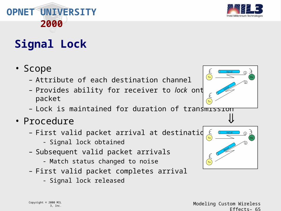
2000Signal Lock
• Scope– Attribute of each destination channel
– Provides ability for receiver to lock onto arriving packet
– Lock is maintained for duration of transmission
• Procedure– First valid packet arrival at destination channel
- Signal lock obtained
– Subsequent valid packet arrivals- Match status changed to noise
– First valid packet completes arrival- Signal lock released
RxTx
Tx
1
2
Valid
Valid
RxTx
Tx
1
2
Valid
Noise

Copyright © 2000 MIL 3, Inc. Modeling Custom Wireless Effects– 66
OPNET UNIVERSITY
2000Stage 7: Receiver Power
• Invocation– Once for each destination channel– Called immediately after stage 6 - no intervening events
• Purpose– Computes signal power level at receiver– Typically based on transmitter power and frequency, distance, and antenna gains– Computed only for valid and noise packets
• Requirements– Sets RCVD_POWER TDA
• Results– Kernel uses value to record receiver power channel statistic– Places packets in separate lists based on match status

Copyright © 2000 MIL 3, Inc. Modeling Custom Wireless Effects– 67
OPNET UNIVERSITY
2000Stage 7: Receiver Power (default)
• Name– dra_power
• Computation– Determines if signal lock is active
– Computes received power- valid and noise packets
- Computes path loss - free space
- Determines in-band transmission power
- Obtains tx and rx antenna gains
• Result– Value placed in RCVD_POWER for use by stage 9
(watts) GainAntenna Receiver
(watts) GainAntenna r Transmitte
(watts) Power Received
Bandwidth
(Hz) FrequencyMinimum
(Hz) FrequencyMaximum
(watts) Power dTransmitte
FrequencyInband
quencyCenter Fre
Lightof Speed
Distance
Wavelength
Pathloss
rx
tx
min
max
G
G
P
B
f
f
P
P
f
C
D
L
rx
tx
i
c
p
rxptxir
tx
c
p
GLGPB
ffPP
f
C
DL
x
minmaxi
2
P
4

Copyright © 2000 MIL 3, Inc. Modeling Custom Wireless Effects– 68
OPNET UNIVERSITY
2000Stage 8: Background Noise
• Invocation– Called immediately after stage 7 - no intervening events
• Purpose– Represents effects of all background noise sources– Typically includes
- thermal or galactic noise- neighboring electronics emissions- other unmodeled radio transmissions (commercial/amateur radio, TV)
• Requirements– Sets BKGNOIS TDA
• Results– Typically used by stage 10 in signal-to-noise computation

Copyright © 2000 MIL 3, Inc. Modeling Custom Wireless Effects– 69
OPNET UNIVERSITY
2000Stage 8: Background Noise (default)
• Name– dra_bknoise
• Computation– Constant ambient noise
– Constant background noise
– Constant thermal noise
• Result– Value placed in BKGNOISE for use by stage 10 in signal-to-noise computation
ab
rxa
rxbkrxb
bk
rx
NNN
BN
kBTTN
k
T
NFT
26
23
E0.1
E379.1
0.290
0.290*)0.1(
NoiseN
N
N
B
k
T
T
NF
a
b
rx
bk
rx
NoiseAmbient
Noise Background
andwidthReceiver B
Constant sBoltzmann'
eTemperatur Background
eTemperaturReceiver
FigureNoise

Copyright © 2000 MIL 3, Inc. Modeling Custom Wireless Effects– 70
OPNET UNIVERSITY
2000Packet Segments
• Portion of packet with constant signal-to-noise– Segmentation performed by kernel
– SNR computation performed by pipeline model
– Upon packet completion, kernel subtracts SNR of completing packet
SNR Variations
1 2 3 4 1SNR Variations
1 2 3 2 1
SNR Variations1 2 3 2 1

Copyright © 2000 MIL 3, Inc. Modeling Custom Wireless Effects– 71
OPNET UNIVERSITY
2000Stage 9: Interference Noise
• Invocation– Only if packet collision occurs
• Purpose– Accounts for concurrent transmissions– Compute the effect of noise on valid packets
• Requirements– Sets NOISE_ACCUM TDA– Sets NUM_COLLS TDA
• Results– Accumulates noise of interfering packets– Noise from packet completing reception is subtracted by kernel– Typically used in stage 10 for signal-to-noise ratio computations
Copyright © 2000 MIL 3, Inc. Modeling Custom Wireless Effects– 72
OPNET UNIVERSITY
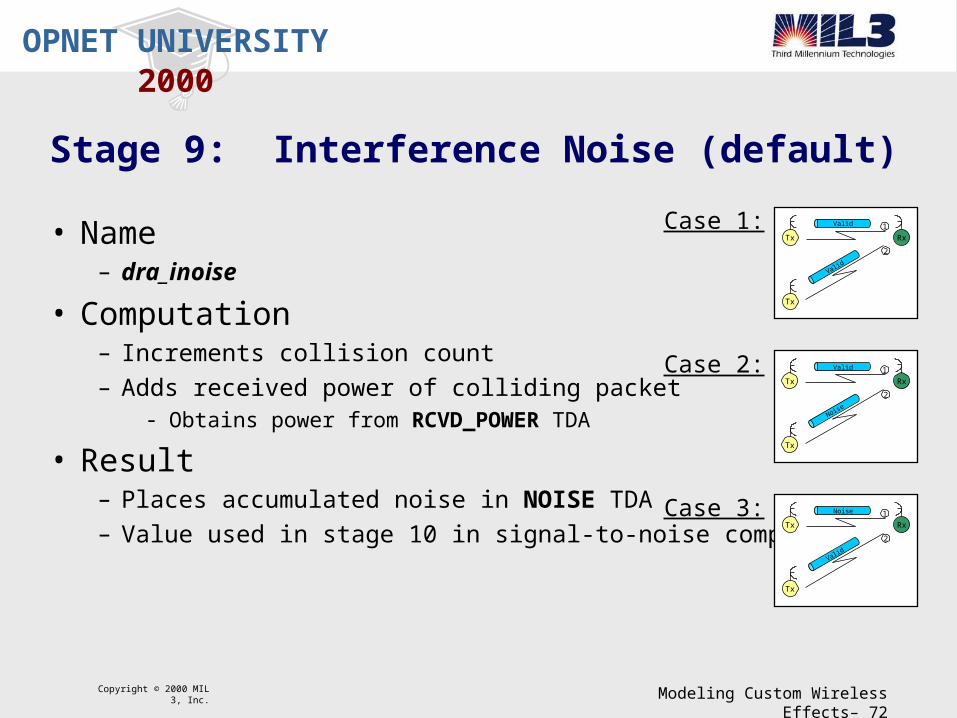
2000Stage 9: Interference Noise (default)
• Name– dra_inoise
• Computation– Increments collision count
– Adds received power of colliding packet- Obtains power from RCVD_POWER TDA
• Result– Places accumulated noise in NOISE TDA
– Value used in stage 10 in signal-to-noise computation
RxTx
Tx
1
2
Valid
Valid
RxTx
Tx
1
2
Noise
Valid
RxTx
Tx
1
2
Valid
Noise
Case 1:
Case 2:
Case 3:

Copyright © 2000 MIL 3, Inc. Modeling Custom Wireless Effects– 73
OPNET UNIVERSITY
2000Stage 10: Signal-to-Noise Ratio
• Invocation (only for valid packets)– Operates on valid packets - those in valid list
– Does not require collision for invocation
• Purpose– Computes the current average SNR
– Typically based on received power and noise
• Requirements– Sets SNR TDA
• Results– Used by kernel to update receiver channel statistics
– Used by later stages
RxTx
Valid
RxTx
Tx
1
2
Noise
Valid
RxTx
Tx
1
2
Valid
Noise
Case 1:
Case 2:
Case 3:

Copyright © 2000 MIL 3, Inc. Modeling Custom Wireless Effects– 74
OPNET UNIVERSITY
2000Stage 10: Signal-to-Noise Ratio (default)
• Name– dra_snr
• Computation– Obtains received power from RCVD_POWER TDA
- Computed in stage 7
– Obtains background noise from BKGNOISE_TDA- Computed in stage 8
– Obtains interference noise from NOISE_ACCUM TDA- Computed in stage 9
– Computes signal-to-noise ratio (in dB)
• Result– Places in SNR TDA– Value used in stage 11 in bit-error-rate computation
)/(log10 10 ibr PPPSNR
(watts) Noise eInterfernc
(watts) Noise Backgroun
(watts) Power Received
i
b
r
P
P
P

Copyright © 2000 MIL 3, Inc. Modeling Custom Wireless Effects– 75
OPNET UNIVERSITY
2000Stage 11: Bit Error Rate
• Invocation– Operates on valid packets - those in valid list– Does not require collision for invocation
• Purpose– Derives the probability of bit errors– Computed for each packet segment - constant SNR– Value typically obtained from modulation curve
• Requirements– Sets BER TDA
• Results– Used by the kernel to record BER statistic– Typically used in stage 12 for allocating errors
RxTx
Valid
RxTx
Tx
1
2
Noise
Valid
RxTx
Tx
1
2
Valid
Noise
Case 1:
Case 2:
Case 3:

Copyright © 2000 MIL 3, Inc. Modeling Custom Wireless Effects– 76
OPNET UNIVERSITY
2000Stage 11: Bit Error Rate (default)
• Name– dra_ber
• Computation– Obtains signal-to-noise ratio from SNR TDA
- Computed in stage 10
– Obtains processing gain from PROC_GAIN TDA- Attribute of receiver channel
– Computes effective SNR
– Determines expected bit-error-rate- Modulation table lookup
• Result– Records BER TDA for use in stage 12 in error allocation computation
pactualeffective GSNRSNR Gain ProcessingpG

Copyright © 2000 MIL 3, Inc. Modeling Custom Wireless Effects– 77
OPNET UNIVERSITY
2000Stage 12: Error Allocation
• Invocation– Called immediately after stage 11 - no intervening events
• Purpose– Estimates bit errors for packet segment
• Requirements– Sets bit-error accumulation in NUM_ERRORS TDA
– Sets empirical bit error rate in ACTUAL_BER TDA
• Results– Kernel maintains a bit accumulator - NUM_ERRORS TDA
– Kernel updates BER statistic - ACTUAL_BER TDA
– Typically used in stage 13 for error correction

Copyright © 2000 MIL 3, Inc. Modeling Custom Wireless Effects– 78
OPNET UNIVERSITY
2000Stage 12: Error Allocation (default)
• Name– dra_error
• Computation– Does not perform bit-by-bit error computations
- Cannot retain bit-error location
– Obtains probability of error - BER TDA
– Computes probability of k errors
– Generates uniform random number: r = (0 1]
– Integrates probability mass over possible outcomes
• Result– Records NUM_ERRORS TDA
N
kk
kNkk
rP
k
NppP
0
)1(
ErrorsofNumber
)1(__
(bits) gthPacket Len
Errorofy Probabilit
Errors ofy Probabilit
k
uniformdistopr
N
p
kPk

Copyright © 2000 MIL 3, Inc. Modeling Custom Wireless Effects– 79
OPNET UNIVERSITY
2000Stage 13: Error Correction
• Invocation– Once for each valid packet– Called immediately after stage 12 - no intervening events
• Purpose– Determines acceptability of arriving packet
• Requirements– Sets PK_ACCEPT TDA
• Results– Rejected
- destroyed by Kernel
– Accepted- forwarded on output stream

Copyright © 2000 MIL 3, Inc. Modeling Custom Wireless Effects– 80
OPNET UNIVERSITY
2000Stage 13: Error Correction (default)
• Name– dra_ecc
• Computation– Obtains threshold from ECC_TRESH TDA
- Percentage of packet in error that still yields acceptability
– Obtains packet length from op_pk_total_size_get ()– Obtains number of errors from NUM_ERRORS TDA
– Computes the percent error
• Result– Packet accepted or rejected depending on threshold and error
– Releases signal lock
length
errors
P
NError%
Copyright © 2000 MIL 3, Inc. Modeling Custom Wireless Effects– 81
OPNET UNIVERSITY
2000Lab: Capture Mode - Overview
• Problem– Default pipeline stages use signal lock
– Systems can lock on to lowest power signal- Higher power signal does not have lock, but dominates channel
- Drowns out lower powered signal
- Causes both communications to fail
• Goals– Modify stages to incorporate signal lock and power lock
– Compare results between the two capture modes
• Purpose– Show additional stage modification
– Incorporate power lock capability

Copyright © 2000 MIL 3, Inc. Modeling Custom Wireless Effects– 82
OPNET UNIVERSITY
2000Lab: Capture Mode - Project/Scenario
• Return to OPNET Modeler (Radio)– Maximize application
• Open project– Capture_Mode
• View scenario– Signal_Lock
- High powered transmitter- Low powered transmitter- Receiver

Copyright © 2000 MIL 3, Inc. Modeling Custom Wireless Effects– 83
OPNET UNIVERSITY
2000Lab: Capture Mode - Choose Results / Simulation
• Observe chosen results– Pulldown menu: Simulation Choose Individual Statistics
- Node Statistics:Radio Transmitter: Traffic Sent (bits/sec)
- Node Statistics:Radio Receiver: Traffic Received (bits/sec)
- Node Statistic:Radio Receiver: Traffic Received High Powered Tx (bits/sec)
- Node Statistic:Radio Receiver: Traffic Received Low Powered Tx (bits/sec)
• Execute simulation– Pulldown menu: Simulation Run Simulation

Copyright © 2000 MIL 3, Inc. Modeling Custom Wireless Effects– 84
OPNET UNIVERSITY
2000Lab: Capture Mode - View Results
• View Results– Pulldown menu: Results View Results– Select statistics
- Object Statistics:Capture Mode:High Powered Transmitter:Radio Transmitter: Traffic Sent (bits/sec)
- Object Statistics:Capture Mode:Low Powered Transmitter:Radio Transmitter: Traffic Sent (bits/sec)
- Object Statistics:Capture Mode:Receiver:Radio Receiver: Traffic Received (bits/sec)
- Object Statistics:Capture Mode:Receiver:Radio Receiver: Traffic Received High Powered Tx(bits/sec)
- Object Statistics:Capture Mode:Receiver:Radio Receiver: Traffic Received Low Powered Tx(bits/sec)
Copyright © 2000 MIL 3, Inc. Modeling Custom Wireless Effects– 85
OPNET UNIVERSITY
2000Lab: Capture Mode - View Results (cont.)
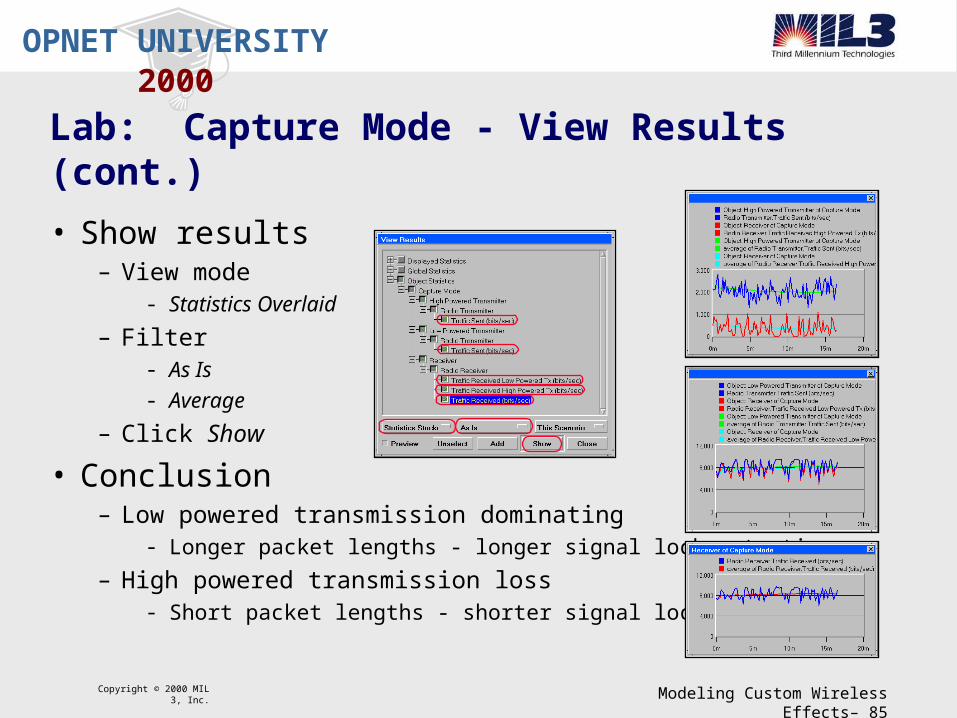
• Show results– View mode
- Statistics Overlaid
– Filter- As Is
- Average
– Click Show
• Conclusion– Low powered transmission dominating
- Longer packet lengths - longer signal lock retention
– High powered transmission loss- Short packet lengths - shorter signal lock retention

Copyright © 2000 MIL 3, Inc. Modeling Custom Wireless Effects– 86
OPNET UNIVERSITY
2000Lab: Capture Mode - Stage Modification Overview
• Goal– Modify three pipeline stages to model power lock– Modifications will eliminate signal lock
• Approach– Modify the pipeline stages
- power model- inoise model- ecc model
– Update Models- Project: Create new scenario- Node: Update node model
– Execute simulation– View results

Copyright © 2000 MIL 3, Inc. Modeling Custom Wireless Effects– 87
OPNET UNIVERSITY
2000Lab: Capture Mode - Open Pipeline Stage
• Open pipeline stage– Return to Windows NT Explorer
– Go to directory containing file- c:\users\student\op_models
– Double click to open file- opnetwork_capture_mode_power.ps.c

Copyright © 2000 MIL 3, Inc. Modeling Custom Wireless Effects– 88
OPNET UNIVERSITY
2000Lab: Capture Mode - Modify Pipeline Stage
• Modify stage– Observe code block in middle of file
- Line 59 through 91
– Cut entire else statement- Line 59: start cutting
- Line 91: end cutting
– Save file

Copyright © 2000 MIL 3, Inc. Modeling Custom Wireless Effects– 89
OPNET UNIVERSITY
2000Lab: Capture Mode - Modify Pipeline Stage (cont.)
• Open pipeline stage– Return to Windows NT Explorer
– Go to directory containing file- c:\users\student\op_models
– Double click to open file- opnetwork_capture_mode_inoise.ps.c
• Modify stage– Modifications already complete
– Observe code block at end of file- Line 69

Copyright © 2000 MIL 3, Inc. Modeling Custom Wireless Effects– 90
OPNET UNIVERSITY
2000Lab: Capture Mode - Modify Pipeline Stage (cont.)
• Open pipeline stage– Return to Windows NT Explorer
– Go to directory containing file- c:\users\student\op_models
– Double click to open file- opnetwork_capture_mode_ecc.ps.c
• Modify stage– Modifications already complete
– Observe code block at end of file- Line 60

Copyright © 2000 MIL 3, Inc. Modeling Custom Wireless Effects– 91
OPNET UNIVERSITY
2000Lab: Capture Mode - Compile Stages
• Compile the pipeline stage– Return to a Command Prompt
– Execute the compile command- op_mko -type ps -m opnetwork_capture_mode_power- op_mko -type ps -m opnetwork_capture_mode_inoise- op_mko -type ps -m opnetwork_capture_mode_ecc

Copyright © 2000 MIL 3, Inc. Modeling Custom Wireless Effects– 92
OPNET UNIVERSITY
2000Lab: Capture Mode - Duplicate Scenario
• Return to OPNET Modeler (Radio)– Maximize application
• Refresh model directories– Pulldown menu: File Refresh Model Directories
– Required for OPNET to know about new files
• Duplicate scenario– Pulldown menu: Scenarios Duplicate Scenario
– Scenario name: Power_Lock

Copyright © 2000 MIL 3, Inc. Modeling Custom Wireless Effects– 93
OPNET UNIVERSITY
2000Lab: Capture Mode - Update Node Model
• Open Receiver node model– Double click High Powered Receiver object
- Node model: no_doppler_rt
• Change receiver module attribute– Right click receiver module– Change attribute
- power model: opnetwork_capture_mode_power- inoise model: opnetwork_capture_mode_inoise- ecc model: opnetwork_capture_mode_ecc
– Save node model- Pulldown menu: File Save As- Filename: capture_mode_power_lock_rr
• Close node Model

Copyright © 2000 MIL 3, Inc. Modeling Custom Wireless Effects– 94
OPNET UNIVERSITY
2000Lab: Capture Mode - Update Network Model
• Return to the Project/Scenario– Capture_Mode-Power_Lock
• Change Receiver node attribute– Right click Receiver node
- Select Edit Attributes
– Change model attribute value- Select Edit...
- Select capture_mode_power_lock_rr
– Close attribute edit box- Select Close
• Execute simulation– Pulldown menu: Simulation Run Simulation

Copyright © 2000 MIL 3, Inc. Modeling Custom Wireless Effects– 95
OPNET UNIVERSITY
2000Lab: Capture Mode - View Results
• View Results– Pulldown menu: Results View Results– Select statistics
- Object Statistics:Capture Mode:High Powered Transmitter:Radio Transmitter: Traffic Sent (bits/sec)
- Object Statistics:Capture Mode:Low Powered Transmitter:Radio Transmitter: Traffic Sent (bits/sec)
- Object Statistics:Capture Mode:Receiver:Radio Receiver: Traffic Received (bits/sec)
- Object Statistics:Capture Mode:Receiver:Radio Receiver: Traffic Received High Powered Tx(bits/sec)
- Object Statistics:Capture Mode:Receiver:Radio Receiver: Traffic Received Low Powered Tx(bits/sec)

Copyright © 2000 MIL 3, Inc. Modeling Custom Wireless Effects– 96
OPNET UNIVERSITY
2000Lab: Capture Mode - View Results (cont.)
• Show results– View mode
- Statistics Overlaid
– Filter- As Is
- Average
– Click Show
• Conclusion– High powered transmission dominating
- Obtaining power lock
– Low powered transmission loss

Copyright © 2000 MIL 3, Inc. Modeling Custom Wireless Effects– 97
OPNET UNIVERSITY
2000Lab: Capture Mode - Summary
• Signal lock– Representative of most systems– Locks on to first arriving signal– All other signals are noise, regardless of power level
• Power lock– Locks on to highest power signal– All other signals are noise– Example: IS-95
- Mobile unit moving between cells- Soft handoff process- Constantly demodulates 3 incoming signals in parallel- Monitors 4th incoming signal- Any of 3 active signals become weak, mobile can switch to high-powered signal

Copyright © 2000 MIL 3, Inc. Modeling Custom Wireless Effects– 98
OPNET UNIVERSITY
2000Conclusion
• Transceiver pipeline– Scope– Capabilities– Default
• Pipeline Modifications– Closure model– Channel match model– Power, Inoise, and ECC models
• Pipeline stages– Flexible– Open– Extensible

Copyright © 2000 MIL 3, Inc. Modeling Custom Wireless Effects– 99
OPNET UNIVERSITY
2000Further Information
• Documentation– Modeling Concepts
- Communication Mechanisms
– General Models- Pipeline Stages / Bus Link
- Pipeline Stages / Point-to-Point Link
- Pipeline Stages / Radio Link