Copper Removal From Steel Scrap Using A Sulfur Matteinfohouse.p2ric.org/ref/25/24371.pdf · COPPER...
218
COPPER REMOVAL FROM STEEL SCRAP USING A SULFUR MA7TE CMP REPORT NUMBER 91-6 February 1991 Prepared by Center for Iron and Steelmaking Research Camegie Mellon University Pittsburgh, PA 15213 principal Investigators R. J. Fruehan A. W. Cramb Prepared for Electric Power Research Institute Center for Materials Production Camegie Mellon Research Institute 4400 Fifth Avenue Pittsburgh, PA 15213-2683 Joseph E. Goodwill CMP Director
Transcript of Copper Removal From Steel Scrap Using A Sulfur Matteinfohouse.p2ric.org/ref/25/24371.pdf · COPPER...

COPPER REMOVAL FROM STEEL SCRAP USING A SULFUR MA7TE
CMP REPORT NUMBER 91-6
February 1991
Prepared by
Center for Iron and Steelmaking Research Camegie Mellon University
Pittsburgh, PA 15213
principal Investigators
R. J. Fruehan A. W. Cramb
Prepared for
Electric Power Research Institute Center for Materials Production
Camegie Mellon Research Institute 4400 Fifth Avenue
Pittsburgh, PA 15213-2683
Joseph E. Goodwill CMP Director

r
FINAL REPORT TO
DEPARTMENT OF ENERGY
Copper Removal from Solid Ferrous Scrap
R. J. Fruehan A. W. Cramb
Center for iron and Steelmaking Research Carnegle Mellon University
Pittsburgh, PA
Co-sponsors
Center for Metals Production Consolidated Natural Gas Center for Iron and Steelmaking Research The Joseph Company uSS Division of USX

'7

Introduction
As discussed in detail in the Appendix, copper is detrimental to the properties of steel. Copper is
present in most forms of recycled swap, such as bundles and shredded scrap. Typical levels of copper in
these forms of swap are 0.2 to 0.4%, whereas critical grades of steel require less than 0.1 and often
0.06% Cu. Therefore, these forms of scrap cannot be used alone to produce quality steels. Steelmakers
must dilute the copper from lower quality scrap with expensive high quality scrap or direct reduced iron
pellets.
Currently there is no effective method lor removing copper from scrap. The only proven method is
improved physical separation which is labor intensive, expensive, and only marginally reduces the copper
content. Chemical treatments, such as sulfide treatment of liquid metal and vacuum, are not effective as
discussed in the Appendix in detail.
Camegie Meilon University developed a concept for removing copper from solid ferrous scrap at
900-1000°C using a FeS-N+S reagent. Small laboratory tests showed 90% of the Cu from simulated
solid scrap could be removed. Based on this concept, DOE funded a project to further develop the
process with cost sharing from the Center for Metals Production, Consolidated Natural Gas, The Joseph
Company and the Center for iron and Steelmaking Research (CMU).
The major results of this study are summarized in this report. Details are given in the reports in the
Appendix.
Scope of Work
Kiln Tests: The major work was run in a large rotary kiln, 0.7 m diameter x 4 m long, using 60-100
kg of scrap. These tests were run to determine the copper removal as a function of time, temperature,
matte composition and scrap type.
Basic Laboratory Tests: Laboratory tests were conducted to determine the rate of the reaction
and the controlling mechanism, the solubility of Cu2S in the matte and the wetability of matte on the
metal.
Dlp Tests: Specific types of scrap, such as motors, were dipped into a bath of matte (10 kg) to
see if Cu could be removed.
Dralnage and Remelt Tests: Special tests were run in the Wln to determine if the matte could be
1
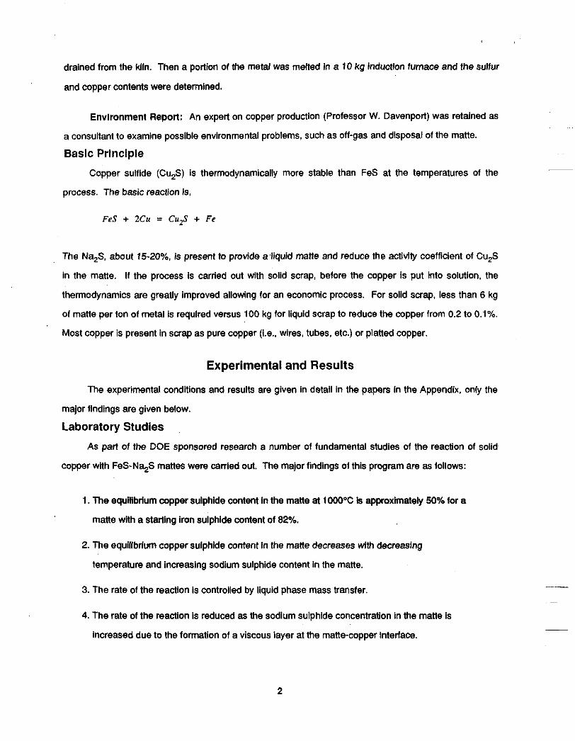
drained from the Wln. Then a poriion of the metal was melted in a 10 kg induction furnace and the sulfur
and copper contents were determined.
Environment Repon: An expert on copper production (Professor W. Davenport) was retained as
a consultant to examine possible environmental problems, such as off-gas and disposal of the matte.
Basic Principle
Copper sulflde (Cu,S) is thermodynamically more stable than FeS at the temperatures of the
process. The basic reaction is,
FeS + 2Cu = CuzS + Fe
The Na,S, about 15-2096, is present to provide a liquid matte and reduce the activity coefficient of Cu,S
in the matte. If the process is carried out with solid scrap, before the copper Is put into solution, the
thermodynamics are greatly improved allowing for an economic process. For solid scrap, less than 6 kg
of matte per ton of metal is requlred versus 100 kg for liquid scrap to reduce the copper from 0.2 to 0.1%.
Most copper is present in scrap as pure copper (i.e., wires, tubes, etc.) or platted copper.
Experimental and Results
The experimental condltions and results are given in detail in the papers in the Appendix, only the
malor findings are given below.
Laboratory Studies
As part of the DOE sponsored research a number of fundamental studies of the reaction of solid
copper with FeS-Na$ mattes were carried out. The major findings of this program are as follows:
1. The equillbrlum copper sulphide content in the mane at 1000°C Is approximately 50% for a
matte with a starting iron sulphide content of 82%.
2. The equilibrium copper sulphide content in the matte decreases with decreasing
temperature and increasing sodium sulphide content in the matte.
3. The rate of the reaction is controlled by liquid phase mass transfer.
4. The rate of the reaction is reduced as the sodium sulphide concentration in the matte is
increased due to the formation of a viscous layer at the matte-copper interface.
2

5. The matte penetrates the grain boundaries of the copper causing smaii pieces of copper to
flake from the whole. In this manner the copper disintegrates as it reacts. The dissolution
reaction rate is therefore quite high and the overall reaction rate is limited by transfer of iron
sulphide in the matte to the reaction zone. Reaction rates of up to 0.15 grams per minute
per cm2 were measured.
6. The matte wets copper, iron and alumina and contact angles of less than 5 degrees were
measured in each case.
7. The reaction should be carried out in a non-oxidizing atmosphere as scale build-up can
interfere with the reaction.
These findings indicate that the process should be carried out within a reaction vessel which
promotes liquid phase mass transfer and a rotating kiln was chosen as an appropriate vessel. in addition,
the 82% FeS - 18% Na,S matte was chosen as the appropriate starting composition.
Tests were also conducted to determine the composition of any gases coming off the process by
analysis with a mass spectrometer. it was found that the sulfur was coming off as SO,.
To determine the efficiency of matte drainage L angles of steel (40 x 40 x 3 mm), steel piate (40 x 2
mm) and a copper sheet (40 x 2) were dipped into an 18% N+S - 82% FeS bath at temperatures of 800,
900 and tO00"C. The samples were emersed for 3 to 5 minutes before being withdrawn from the bath
and air cooled.
The copper sheet was completely dissolved at all temperatures. Results of the drainage
experiments indicated that the amount of mane adhering to the scrap was minimal at 1000°C; however,
signlflcant amounts of matte remained attached to the swap at lower temperatures. These results
suggested that the optimum operating temperature of the kiln would be 1 O0OoC.
Dip Tests
Possible difficult pieces of scrap containing copper were tested by dipping them into a bath (10 kg)
of sulfide matte heated in an induction furnace. Of particular interest were electric motors, a major source
in these tests __
of copper, which may be expected to give problems for the matte to contact the wires. ~
virtually ail of the copper wires were removed by the matte.
3

Kiln Experimental Procedures An externally fired rotary kiln was purchased from CORECO Corp in Milwaukee, Wisconsin. A
schematic of the kiln is given in Figure 1.
The kiln and its supporting frame, hydraulic pump mechanism and exhaust system is approximately
15 feet long, 6 feet wide and 9 feet high. the kiln is fired with natural gas and can reach temperatures in
excess of 1000°C. The stainless steel cylinder which forms the working area of the kiln is two feet in
diameter and twelve feet long. The rotation speed of the kiln can be varied from 1 to 10 rpm. The kiln is
set up so that it can be tilted using a hydraulic pump to facilitate drainage of the matte. The heat is
transported by conduction through the tube wails into the kiln working area. The hot zone was measured
and the experiments carried out within the zone of constant temperature. The steel cylinder surface Is
therefore the hottest part of the working area of the kiln due to this indirect heating method. In order to
contain a pool of matte within the kiln a stainless steel ring was welded into the Inside of the kiln as a
matte dam. Nitrogen gas was fed into the kiln to ptovide a protective atmosphere and an extraction fan
connected to the kiln chimney to exhaust the kiln.
~
In each experiment, 40 - 50 kg of matte and 70 - 80 kg of assorted ferrous scrap (rods, pipes,
angles, plates, etc.) were placed inside the kiln. The matte amount was determined by the minimum
amount necessary to have reasonable matte pool in the kiln. The natural gas was Ignited and kiln rotated
at 2 rpm. Within 20 minutes a pool of liquid matte had formed and the kiln rotation speed increased to 5
rpm. 30 to 40 minutes later, when the matte has completely melted, and the temperature had reach
1000°C, the rotation speed was Increased to 10 rpm.
Once the Wln was at temperature a matte sample was taken. After this sample, additional
quantities of scrap were added to the kiln. The second scrap addltion was of specially prepared scrap
which had a preweighed amount of copper in the form of wire, plpe or tube. In this manner M e total
amount of copper added to the kiln was determined. Generally 3 to 4 kilograms of copper were added to
the kiln during the second scrap addition. The matte was then sampled in 5 minute Increments for 30
minutes. After treatment was completed the kiln was hydraulically tilted, the matte drained into a
collection ladle and a final sample was taken from the ladle.
__.
~
A
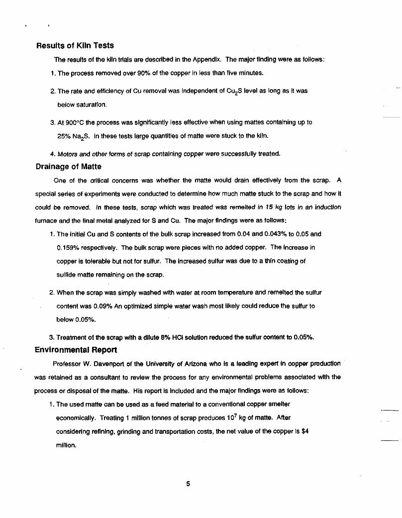
Results of Kiln Tests
The results of the kiln trials are described in the Appendix. The major finding were as foliows:
1. The process removed over 90% of the copper in less than five minutes.
2. The rate and efficiency of Cu removal was independent of Cu,S level as long as it was
below saturation.
3. At 900°C the process was significantly less effective when using mattes containing up to
25% N%S. in these tests large quantities of matte were stuck to the kiln.
4. Motors and other forms of scrap contahlng copper were successfully treated.
Drainage of Matte One of the critical concerns was whether the matte would drain effectively from the scrap. A
special series of experiments were conducted to determine how much matte stuck to the scrap and how it
could be removed. In these tests, scrap which was treated was remelted in 15 kg lots in an induction
furnace and the final metal analyzed for S and Cu. The major findings were as follows:
1. The initial Cu and S contents of the bulk scrap increased from 0.04 and 0.043% to 0.05 and
0.159% respectively. The bulk scrap were pieces with no added copper. The increase in
copper is tolerable but not for sulfur. The increased sulfur was due to a thin coating of
sulfide matte remaining on the scrap.
2. When the scrap was simply washed with water at room temperature and remelted the sulfur
content was 0.09% An optimized simple water wash most likely could reduce the sulfur to
below 0.05%.
3. Treatment of the scrap with a dilute 8% HCI solution reduced the sulfur content to 0.05%.
Environmental Repon Professor W. Davenport of the University of Arizona who Is a leading expert In copper production
was retained as a consultant to review the process for any environmental problems associated wlth the
process or disposal of the matte. His report Is included and the major findings were as follows:
1. The used matte can be used as a feed material to a conventional copper smelter
economically. Treating 1 million tonnes of scrap produces 10’ kg of matte. After
considering refining, grinding and transportation costs, the net value of the copper is $4
million.
5
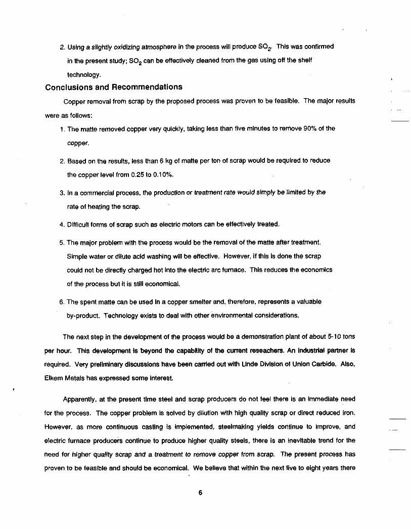
2. Uslng a slightly oxidizing atmosphere In the process will produce SO,. This was confirmed
in the present study; SO, can be effectively cleaned from the gas using off the shelf
technology.
Conclusions and Recommendations
Copper removal from scrap by the proposed process was proven to be feasible. The major results
were as follows:
1. The matte removed copper very quickly, taking less than five minutes to remove 90% of the
copper.
2. Based on the results, less than 6 kg of matte per ton of scrap would be required to reduce
the copper level from 0.25 to 0.10%.
3. In a commercial process, the production or treatment rate would simply be limited by the
rate of heating the scrap.
4. Difficult forms of scrap such as electric motors can be effectively treated.
5. The major problem with the process would be the removal of the matte after treatment.
Simple water or dilute acid washing will be eflective. However, if this is done the scrap
could not be directly charged hot into the electric arc furnace. This reduces the economics
of the process but it is still economical.
6. The spent matte can be used in a copper smelter and, therefore, represents a valuable
by-product. Technology exists to deal with other environmental considerations.
The next step in the development of the process would be a demonstmtion plant of about 5-10 tons
per hour. This development Is beyond the capability of the current reseachers. An Industrial parmer Is
required. Very prelimlnaty discussions have been carried out with Unde Division of Union Carbide. Also,
Elkem Metals has expressed some Interest.
Apparently, at the present time steel and scrap producers do not feel there is an Immediate need
for the process. The copper problem is solved by dilution with high quality scrap or direct reduced iron.
However, as more continuous casting is Implemented, steelmaking yields continue to improve, and
electric furnace produceis continue to produce higher quality steels. there is an inevitable trend for the
need for higher quali i scrap and a treatment to remove copper from scrap. The present process has
proven to be feasible and should be economical. We believe that within the next five to eight years there
__
~
6

will be sufficient incentive for a scrap processor to employ this technology. in the short term the potential
of the process could keep down the price of high quality scrap by providing a potentlal altemative.
7

stainless steel ring
I Matte 7
I
a

Optimum Atmospheric Conditions for Decopperizing Steel with FeS-Na,S Matte
W. G. Davenport, Ph.D., P.E. University of Arizona
Tucson, AZ '85721 November 5,1990
9

Optimum Atmospheric Conditions for Decopperizing Steel uith FpS-IU9.S M p t t ~
The proposed steel decopperization process consists of contacting solid steel with liquid FeS-Na$ matte at 900-1000°C. The matte absorbs Cu from the steel until the thermodynamic activity of Cu in steel and matte is nearly the same.
A potential difficulty with the process is sulfur evolution into the workplace and/or environment. However, the equilibrium sulfur pressure of Fe-saturated Cu,S:FeS matte at 1000°C is only l@' atmospheres") so that sulfur evolution should not be rapid.
The question this report addresses is whether the decopperization process should be carried out under:
(a) oxidizing conditions in which case the evolved sulfur will be oxidized and leave the furnace as SO2;
(b) reducing conditions in which case the evolved sulfur will be in the form of gaseous sulfur and H,S.
Industrial contacts indicate that oxidizing conditions would be preferable. The author of this report concurs with their suggestion.
The rationale of the suggestion is that proven off-the-shelf technologies exist for removing SO, from furnace gases.* Further, it is likely that sulfur and H,S gases (from decopperization under reducing conditions) would most easily be removed by after- burning and SO, removal. This would seem to be overly complex.
'Depending on the quantity of SO,, sodium or calcium hydroxide solutions are used in the off-the-shelf SO, absorption systems.
~
'Gaskell, D. R., Palacios, J. and Somsiri, C., 'The Physical Chemistry of Copper Mattes," in The Eliott Svmu . osium, Iron and Steel Society (AIME), New York, 1990, pp. 151-162.
10

Feasibility of Selling Steel-Decopperization Byproduct Matte
W. G. Davenport, Ph.D., P.E. University of Arizona Tucson, AZ 85721 November 5, 1990
1 1

Feasibility of Selling Steel-Decopperization Byproduct Matte
The byproduct matte from steel decopperization is similar in composition to the concentrates normally treated by primary copper smelters. Industrial personnel contacted during this study indicate that the byproduct matte could be smelted along with normal copper concentrates. The matte would have to be crushed and ground to -100” (-150 mesh) for this purpose.
Having concluded that smelting of the matte poses no significant problems, the rest of this report examines the economics of smelting the matte in a primary copper smelter.
1. Decopperization matte production rate
About 106 tonnes of steel will be decopperized per year. About 10 kg of byproduct matte (34% Cu,S, 65% FeS, I%Na$, i.e. 27% Cu) will be generated per tonne of steel. This is equivalent to a production of 10 x 106 kg or 10 000 tonnes of byproduct matte per year.
This quantity of matte is equivalent to 1/2 to 1 week’s input to a western U.S.A. copper smelter. It is about 100 train-car loads of crushed matte.
2. Prices and costs
Electrolytic copper is currently selling at a spot price of $1.30 per pound (New York Times, November 3, 1990).
The cost of smelting the matte and refining and selling the resulting copper will be about $0.50 per pound of copper (industry source). The cost of transporting the matte from the eastern U.SA to a western U.S.A. smelter will be about $0.10 per pound of copper. Therefore, the total treatment cost will be about $0.60 per pound of copper.
Smelting the matte will generate a sizeable positive cash flow @lease see appendix). There will, of course, be handling costs at the seller’s site but these will be incurred whether or not the matte is sold.
3. Crushing and grinding
The matte will have to be crushed and probably ground before smelting. It will probably be crushed to about -2 inch diameter before shipping; then ground at the smelter site. Most smelters have suitable grinding facilities. A small crushing and grinding cost will be incurred.
12

4. Impurities
This report assumes that the matte contains no impurities except sodium. Normally, there is nothing in steel that should be a problem in a copper smelter. Zinc from galvanizing might be a problem if it is more than 1% in the matte.
5. Conclusion
Smelting of steel-decopperizing matte by primary copper smelters is technically and economically feasible. It will be the best way of dealing with the matte.
13

Appendix
Calculation of Cash Flow from Treatment of Steel Decopperization Matte
Assumptions:
10 000 tonnes of matte per year, 27% Cu This is equivalent to 2700 tonnes of Cu per year or:
= 6 x 10⁶ pounds Cu per yr. 22 nds ytrGe 2700 tonnes Cu per year x
Net return $ per pound of Cu = Sales price per pound of Cu - Costs per pound of Cu
= $1.30 - $0.60 = $0.70
Net cash flow, $ per year = pounds of Cu per year x net return, $ per pound of Cu
= 6 x lo6 pounds Cu per year x $0.70 per pound of Cu
= $4 x lo6 per year
14
APPENDIX


APPENDIX CONTENTS
Page
A New Process for Copper Removal from Ferrous Scrap
Recent Progress on Ferrous Scrap Pretreatment
ClSR Progress Report: Refining of Copper from Solid Ferrous Scrap
1
39
57
Report for Prellmlnary Experiment: Observation of interfaces Between Solid Copper and Llquld Matte, and between Solid-iron and Llquld Matte 89
ClSR Progress Report: Preliminary Experlments for Removlng Copper from Ferrous Scrap 99
ClSR Progress Report: Removing Solid Copper from Solid Scrap-lnltlal Kiln Experlments 107
ClSR Progress Reports: Removlng Copper from Ferrous Scrap In a Kiln 123
Decopperlzation of Ferrous Scrap 145
ClSR Progress Report: Fundamentals of Decopperlratlon from Solid Scrap 155
ClSR Progress Report: Fundamentals of Decopperlzatlon from Solid Scrap 165

0

A New Process For Copper Removal From Ferrous Scrap
by
Alan W. Cramb and Richard J. Fruehan
Deparlment of Materials Sdence and Metallurgical Engineering Camegie Mellon Unlverslty
Pittsburgh. PA 15213
Summaw
A new process for the separafion of solid copper from solid ferrous scrap has been developed within
the Center for Iron and Steel Research at Camegle Mellon University. The process which uses a liquid
Iron sulphide - sodium sulphide matte to react with solid copper at 1oooOC. has been shown to be
technically viable in small scale (100 kg) experiments In a rotary kiln. The process is optimal if run under
a nonoxldWng atmosphere and complete separation of the matte from the scrap can be affected by
drainage at temperahrre followed by a hot add wash. Details of the experimental program and Its findings.
suggested matte chemistries and potential problems are disfflssed.
Introduction
The potential build-up of residual elements In steel Is a cause for concern wlthln both the steel and the
scrap hdusWes. High levels of elements such as copper, nickel, molybdenum, tin and chromlum are
thought to be deleterious to product consistency and have also been shown to cause pmblems dudng
casting and subsequent processing.lll The absoiute ievei at which a “I e m bec~nes
deleterious to product quality Is dependent upon the applicatlon; however, it seems reasonable to assume
that, at some time In the Mure, prudent background levels of residual elements WI be exceeded, leading
to scrap sorling or pretreatment as a routine operation before charging Into an e l d c arc fumace. __
__ The problem of Increasing copper residuals In steel Is recognized to be a future problem in the steel
industry. The growth of electric arc fumace steelmaklng’ and the decreasing quantities of ”home” saap in
the major integrated producers, due to Increased use of continuous casters, has lead to a greater
1

demand for quality scrap and Increased residual levels In steel products. Large integrated producers can
always dilute with hot metal and tolerate higher scrap copper contents; however, even this practice has
limits. The problem Is more difficult for electric fumaca operators who must have an exact scrap analysts
in order to meet the maximum allowed residual levels for a certain grade. Dilution, Wh prereduced Iron. is
also an option for electric arc furnace operators If it is economically feasible. A simpler solution is to find a
method of removing copper from the solid scrap or to remove the copper from liquld steel.
Due to the future Importance of this problem, a number of studies have been carried out at Camegie
Meilon University to develop an economical refining process to extract copper from contaminated scrap
121. The outcome of the inMal work was the realization that ladle processes were unlikely to be economical
due lo low copper distribution ratio's and high reagent or equipment costs. A lower temperature ( 10W°C)
solld scrap treatment process was conceptualized and initial laboratory scale experiments indicaied that
the process was chemically feasible. As a result a projeci was proposed to and accepted by the
Department of Energy and, in October of 1988, trials were lnltlaied to determine the technical feaslbfllty of
a low temperature matte pmcess for the separalton of solid copper from saap. The purpose of thk paper
k lo report the results of this expedmental program whlch Indicates that li is teohnlcally feasible to
separate solid copper from solld scrap ai 1000°C uslng a llquld FeS-Na$ matte.
Backqround
Copper Induced Defects
The CopperresMual prOMemiswel1 reoognized h boththesdldnlcetlon anddetonnation pIocessingof
steel. Qms defeds have been found during the testing, fulling and welding of steels wlth slgniticant
copper resldualsP4~, while variations In product properties have been correlated to copper variations In the allofl.
Casting and rolling defects are caused by embrlttlement due to the formation of a llquid copper film
which forms when the iron is preferentially oxidized during the formation .of s~aIe~~*~1. This preferential
oxidation causes an enrichment in copper and other residuals such as nickel, tin and antimony in the
grain boundaries. As can be seen In Figure 1, concentration of copper In the grain boundaries leads to
2

the formation of a liquid Rim at temperatures greater than 11 oO°C and causes the phenomenon classically
known as 'hot shortness', Le.. intergranular decoheslon which leads to aad(1ng upon subjecting the
casting to a shear stress at high temperatures. This phenomenon of liquid copper film embmiement of
steels in an oxidizing atmosphere is well documented, was originally proposed by Pfeli~lo~ and was
discussed by a number of authors during the slk-ties~ll - "1. One suggested method of eliminating this
defect is to ensure that a solid lntermetalilc compound of copper and nickel is formed by setting the
copper to nldcel ratio In the steel at 3 : 1 or large@; however, at higher copper levels (0.35%) substantial
quantities of nickel (0.12%) would have to be intentionally added, or blended by scrap sorting, to ensure
avoidance of the defect. An aematlve approach is to ensure that copper residual levels are low or that
scale formation is minimized during processing.
A copper Induced crack which is very common in continuous cast slabs and blooms is the star aack. ThIs aedc is caused by localized surface concentrations of copper which are due to wear of the
contmuous casting mold. Again the cracks are caused by thin liquid copper films which penetrate the
grain boundaries leading to embrfttlement. This problem is generally countered by coating the molds with
a more abrasive resistant materiai such as chromium or nickelIf5W
Treatment of Liquid steel
The copper problem is well recognized In pradlce and in the literature and has been the subject of a
number of studies over the past thitly years. A major goal of a number of researchers was to develop a
technique to remove copper from the liquid steel after scrap melting. A review of ladle processes for the
removal of copper from UquM steel was recently published by Jimbo et ai~21 and deWls of the various
technigues aregiven hTabk 1.
Reagent treatment of liquid steel, either by liquid lead or by a sulphide matte. Is pradicany lnfeaslbk
due to the low copper distribution ratlo's. Le., the equlllbrium ratio of copper In the reagent to copper In
the liquid steel at a given temperature. which are found in the ament chemical ladle processes. For
example, in blais at the Bureau of Mlnesl'v in a 1.5 ton pilot operation. only 40% of the copper was
removed from the liquid steel using 200 ib of an FeS-N+S mixture per ton of carbon saturated Iron. in
both the sulphide slagging and the lead process, reagent costs will be high and results poor. Although
technically feasible, thew processes are economically Infeasible due to equipment and reagent costs.
- __
~
3

Vacuum processes for copper removal are kinetically limited and not feasible for large heat sizes. Even
for small heat sizes the process would be capitally expensive and time consuming. Therefore, removal 01
copper from liquid steel In the ladle does not seem a viable altemative at this time.
Treatment of Solid Steel
90% of the copper present in smap exists primarily as pure copper in the form of wire or platted
materlai. In Table Ii processes for copper removal from solid scrap such as physical separation,
preferential meltlng, acid treatment and the matte process, which is the subject of this paper, are
reviewed.
Cumntly physical separation and pracUces of raw material segregation are widespread in the s a a p
i ndu~by [~~ .~~1 . In Table 111, the beneMs of a scrap sorting program are Indicated. Although major
reductfons In scrap copper content can be affected through saap sorting It Is not possible to reduce
copper levels to very low levels using this technique. Physical separatlon and sorting of scrap Is time
consuming. labor Intensive, expensive and cannot reduce the overall copper contents to less than 0.05%;
a level necessary for the production of flat products vla an electtic steelmaking mute.
Preferential melting technlques proved unsuccessful due to dWculties In the seperauMl of the IiguM
copper from the steel[202rl. If copper can cause hot shortness then liquid copper must be able to
penetrate and flow along grain boundaries. Therefore, copper wets solid Iron and preferential melting of
copper will be unsuccessful as a large portion of the copper will plate the Iron surface making separation
very dMwIt. The last two processes: that of a matte treatment at temperatures less than 1000°C and 811
add treatment both appear to be conceptually feasible.’ The dissolvtion of copper in an add Is chemically
feasibletherefore~uchapmxscouldbedeveloped.~
The low temperature matte process was Invented at Camegle MeNon Unhrerse and %ill be the
subjeu of the remainder of this paper. The process Is an extension of the sulphide slagging or matte
process that was used In the ladle. The major difference Is that the procsss Is canied out at loooOC while
the scrap is solid and the matte Is liquid. Clearly the procass Is also a swap preheating procass which
4

means that H may be possible to combine both functions in one process. Due to the economic
lmplicatlons of a preheated scrap source, 1.0.. H Is cost effective to preheat scrap with a cheap energy
source such as natural gas before charging to an electric fumace. this process was subjected to an
ecunomic analysis which suggested that direct charging of the preheated treated scrap could result in a
total process cost savings of $ 20 per ton of steel produced, due to cost savings at the electric arc
furnace, if the low copper scrap dlfferentiai was $40.00 per ton. Due to this Overall process potential the
matte process was developed at CMU.
Process Principles
This process Is based upon two fundamental principles: (1) Copper can be transformed by chemical
reactlon from the solid state to a liquld, and, (2) The copper containing liquid can be completely separated
(by drainage) from the scrap. In this manner solid copper can be completely removed from solid screp.
Chemistry
The chemistry of the process is based upon the fobwing readion:
2 Cu + FeS - Cu,S + Fe .... [I]
where solid copper ream wrth iron sulphide to form copper sulphide while precipltaling solid Iron at the
tmpera t” of interest (e loooOC ). This is, of course, the readion which was the basis for the ladle
sulphide slagglng pmcess oflginated by Jordan In 1Q5d2)1; however, in tMs process, the reaction takes place at a much lower temperature while the s a a p and copper are solid and separate.
Reaction 1 proceeds as written at temperatures above 61 4OC if the products and reactants are solld. At
lOOOOC the equilibrium constant of reaction 1 has a value of 2 6 and solld copper can reduce iron
sulphide. Low temperature solid-solid reactions are generally slow being limited by the rate of diffusion
and the contact area’ Uquld-solid reactions are usually preferred as there is a larger contad area and the
liquid phase dlffusivilies are much higher than that of the solid. Fortunately, mixtures of sodium sulphide,
iron sulphide and copper sulphide have large areas of their phase diagrams which are liquid below
5

1000°C thus, the process can be Initiated wltfi a liquid matte contahling a mixture of iron and sodium
sulphide. As can be seen in figure 2, the liquid phase field at looO°C stretches from approximately 15 to
83% iron sulphide.. Sodium sulphide is present Only to iiquify the matte at treatment temperatures and the
reaction of Interest is with iron sulphide; therefore. high iron sulphlde containing mattes are chosen to
initiate the process. Normally the starting matte chemistry for the process was 82% Iron sulphide and
18% sodium sulphide for funs at 1000°C and 75% iron sulphide and 25% sodium suiphlde for runs at
900%.
As the reaction proceeds the iron sulphide in the matte is replaced by copper sulphide in an Ionic
exchange reaction where solid iron is precipitated and copper Ions enter the matte phase. Thus the solid
capper is transformed into copper ions dissolved in the liquid matte until either the copper sulphide
solubility limit In the matte or the equilibrium condition of equation 1 is reached. Fortunately copper
sulphide is almost completely miscible in the liquid Iron sulphide - sodium sulphide mattes which are
appropriate for this process (flgure 3) and the matte fluidity increases "I quite large additions of copper
sulphide. This is Important as process SUCCBSS depends upon nol only reaction of copper wlth the matte
bot subsequent drainage of the matte In order to allow separation of the copper from the scrap. The steps
of reaction plus separation are the keys to any successful high temperature procsss and failure to
accomplish both steps will lead to plocess failure.
Recalculaflon of the thermodynamics ot reaction 1 for the reaction of solid copper with a liquid iron
sulphide to form a liquid copper sulphide and solid iron yields a an equiilbrium constant at 1000°C of
approximately 5 for this thermodynamically favorable reaction. The equllibiium constant for reaction 1
can be written as follows:
'F* 'Cq
'Cu 'Fa 2 K =
Thus to maximize the amount of copper In the matte it is necessary to maxlmke the actMty of copper and
iron sulphide and to minimize the activity of copper sulphide In the starting matte. it is also more faVorable
to treat solid copper (a, - 1) than to treat copper dissolved in ilquld Iron. In addition. as sodium sulphide
reduces the activity of copper sulphide in the matte, it also aids in Improving the thermodynamics of
copper removal.
6
Reactlon Rate
As part of the DOE sponsored research a number of fundamental studies of the reaction of solid
copper with FeS-N%S mattes were carried out. The studies will be reported in detail in a subsequent
publication [24]. The major findings of this program are as follows:
1 . he equilibrium copper sulphide content in the matte at looO°C is approximately 50% for a
matte with a starting Iron sulphide content of 82%.
2.The equilibrium copper sulphide content in the matte decreases wlth decreasing
temperature and increasing sodium sulphide content In the matte.
3. The rate of the reaction Is controlled by liquid phase mass transfer.
4. The rate of the reaction Is reduced as the sodium sulphide concentratlon in the matte is
inmased due to the formation of a viscous layer at the matte - copper interface.
5. The matte penetrates the grain boundaries of the copper causlng small plecas of copper to
flake from the whole. In this manner the copper disintegrates as It reads. The dissolution
reactlon rate is therefore qulte high and the overall reaction rate Is limffed by transfer of Iron
sulphide in the mane to the reactlon zone. Reaction rates of up to 0.15 grams per minute
per cm2 were measured.
6. The matte wets wpper, Iron and alumina and contact angles of less than 5 degrees were
measured in each case.
7.The reaction should be canled out In a non-oxldlzing trrmoephere as soale bulld-up 08n
Interfere wlth the reectlon.
These flndlngs indicate that lhe process should be carried out Whin a reactlon vessel which promotes
liquid phase mass transfer and a rotating kiln was chosen as an appropriate vessel.
Matte Drainage from Scrap
- To determine the efficiency of matte drainage L angles of steel (40 x 40 x 3 mm). steel plate (40 x 2
mm) and a copper sheet (40 x 2) were dipped into an 18% N e - 82% FeS bath at temperatures of 800.
7

900 and 1000 C. The samples were Immersed for 3 to 5 minutes before being withdrawn from the bath
and air cooled.
The copper sheet was completely dissolved at all temperatures. Results of the drainage experiments
are given In Figures 4 and 5. where the AM% Is the weight gain upon removal from the matte. In both
cases the amount of matte adhering to the scrap was minimal at 1000°C; however, significant amounts of
matte remalned attached to the scrap at lower temperatures. These results suggested that the optimum
operating temperature of the kiln would be 1000°C.
Kiln Desiun
An externally fired rotary kiln was purchased from CORECO, Cop In Milwaukee, Wisconsin. A
schematlc of the klln is glven In figwe 6. The Idin was installed at the USX pibt fadlity in Universal, PA,
where a bulldlng was constructed to house the Idin. Elec(cldty and gas hodcvps and supply were
supplled by the AIS1 direct steelmaklng task force who were also on-site at the Hme of the tdals.
The Wln and Its supporting frame, hydraulic pump mechanism and exhaust system is approximately 15
feet long, 6 feet wide and 9 feet high. The kiln Is Rred with natural gas and can reach temperahnes In excess of 1 OOOOC. The stainless steel cylinder whlch forms the woddng area of the kiln is two feet In
diameter and twelve feet long. The rotation speed of the kiln can be varied from 1 to 10 rpm The Win is
setup so that it can tilted uslng a hydraulic pump to fadlltate drainage of the matte. The heat is
transported by conductlon through the lube walls into the kiln woddng area. The hot zone was measured
and the experiments carried outwllhln the zone of amstant temp”. The steel cyilnder surface is therefore the hottest part ofthe d n g area ofthe ldln duet0 WS indirect heating “ad. In onierta
contaln a pool of matte within the kiln a stalnless steel ring was welded Into the Inside of the kiln a8 a
matte dam. Nitrogen gas was fed Into the kiln to provide a protective atmosphere and an extraction fan
connected to the kiln chhnney to exhaust the kiln. A schematlc of the lntemal configuration of the kiln is
given In figure 7 and operational and drainage schematics are given in figure 8.
8

Experimental Procedure
A typical experimental procedure and schedule of sampling is outlined In figure 9. In each experiment
40 - 50 kg of matte and 70 - 80 kg of assorted ferrous scrap ( rods, pipes, angles. plates etc..) were
placed inslde the Win. The matte amount was determined by the minimum amount necessary to have
reasonable matte pool in the Win. The natural gas was ignited and the Win rotated at 2 rpm. Within 20
minutes a pool of liquid matte had fomed and the Win rotation speed increased to 5 rpm. 30 to 40
minutes later, when the matte had completely melted and the temperature had reached 1000°C, the
rotation speed was increased to 10 rpm.
The matte, at temperature, was very fluid and could be seen to wet the scrap easily. Generally, the
matte was added In its hydrated state. A small amount of fume was given off during initial pool formation
but no eruptlon or excessive amounts of reaction were noted. Apparently. the slow heating rate was
sufficient to drive off any water content in the original matte starling materials. A limited amount of gas
sampling was canled out to determine the composition of the gaseous spedes given off from the matte.
In an open atmosphere a limited amount ol SO2 could be detected. During klln operation a small amount
of smoke could be seen in the Win.
Once the idin was at t e m p " a matte sample was taken. After this sample addltlonai quarttitles of
scrap were added to the klln. The second scrap addition was of specially prepared scrap whlch had a
prewelghed amount of copper In the form of wire, pipe or tube. In this manner the total amount of copper
added to the kiln was detennined. Qenerally 3 to 4 kliograms of copper were added to the kiln during the
second scrap addition. The matte was then sampled in 5 mlnute i " e n t s for 30 minutes. Alter
tmabnent was completed the klkr was hydraulically tilted, the matte drained Into a cdledlon ladle end a
final sample was taken from the ladle.
After the treat" was complete and the matte drained. only a thln layer ol matte was left sticklng to
the kiln. After the experiment the matte and scrap was carefully examined for the presence of solid
copper. In no case was any solld copper discovered in either the matte or the saap .
9

Results and Discussion
A number of trials were conducted in the Win. The major emphasis in the kiln Mais were to determine:
1. The viability of the process.
2. The ability of the process to remove copper from electric motors.
3. The temperature range over which the process is applicable.
4. The effectiveness of matte drainage after prOC%SSing
Chemical analysis of the matte was used to determine the effediveness of the process and swap
remelting was carried out to determine the detrimental effects of the matte which was left sUcWng to the
scrap.
Initial Experiments
The fitst series of experiments which were carried out after assembly, setup and thermal
characterization of the kiln were dmed at detemdnlng the basic operational vieMlHy of the Mln. The
temperature was set at 1 oooOC and the initial matte chemistry was 82% FeS - 1 B%Na$.
Initial experimental results for copper sulphlde picitup and the change in iron sulphide and sodium
sulphide contents are given In figures 10 - 12. As can be seen In these figures % CyS increases far the
first 7 minutes of the bid, followed by a gradual deaease, Sodium sulphide decreases throughout the
experiment while Iron sulphkle deaeases at first and then kraeases. Theoretical emlysk of
the reaction assuming a linear reactIan rate would give the curve shown In flgure 13 and hrdlcates that
iron and sodium sulphide contents should deaease In the matte as the copper sulphide content
increases. The actual results Indicate that something else must be happening during the reaction which
affects the matte. In addition to the matte chemical analysis. a mass balance for copper In the process
indicated that the maximum recovery of the copper in the matte was 90.2% withln 5 minutes of addition
and that recovery deaeased to 66.6% after 35 minutes. The matte was either increasing In volume as a
function of time or the copper was reprecipitating from the matte. The matte was thoroughly examined for
any solid copper content and none was found; however, It was noted during the experiments that the
__
__
10

ends of the saap rods were significantly thinner at the end of the experiment than at the beginning. n was
postulated that the reoxidation of iron resulted in the formation of FeO which dissolved in the matte. This
seemed reasonable as the sodium sulphide content decrease was too large to be accounted for by
stoichiometry and that the iron sulphide content decrease was not large enough.
Matte dremlcal analysis was by a "wet" technique where the matte was first dissolved in add and the
concentraUons of iron, sodium and copper determined. in this analysis technique we determine total iron
and all graphs are plotted assuming that ail iron is present as iron sulphide. Therefore the presence of
iron oxide in the matte would appear as increased iron sulphide contents in the matte chemistly.
A second set of experiments were conducted on mattes with higher starting copper sulphide Content
than the inifid experiments (10% vs %) and revealed similar results ( figures 14 and 15) where the
copper sulphide deaeased as a function of time after reaching a maximum value. The calculated copper
reawecy in the matte only reached 85% before deaeasing to an apparent 55% after 45 minutes. Again
the ends of the scrap rods were signMcenUy thinner at the end of the experiment than at the beginning
and the apparent lron sulphide content of the matte increased near the end of the experiment indicating a
reoxldation problem.
The atmosphere inside the Idin. elthough attempts had been made to purge with nltrogen. dearly was
not inert due to difficulues in sealing the hot kiln. In addition. due to some smoke problems, an exhaust
extradion fan was added to the Win which caused a draught through the Idin. Thus, the iron oxide which
was formed dlssdved into the matte, increasing Its volume. and accounted for the apparent increase in
matte volume. Thls effect was dew seen dudng a tdal using a 75% FeS - 25% Na$ matte at 1000°C.
lni igm 16 the typical coppersulpMde resun can be seen where within 7 minutes a maximum Is reached
which ac" lsfor95%of the copper added tothe Idln. Subsequently the copper sulphMe man In the
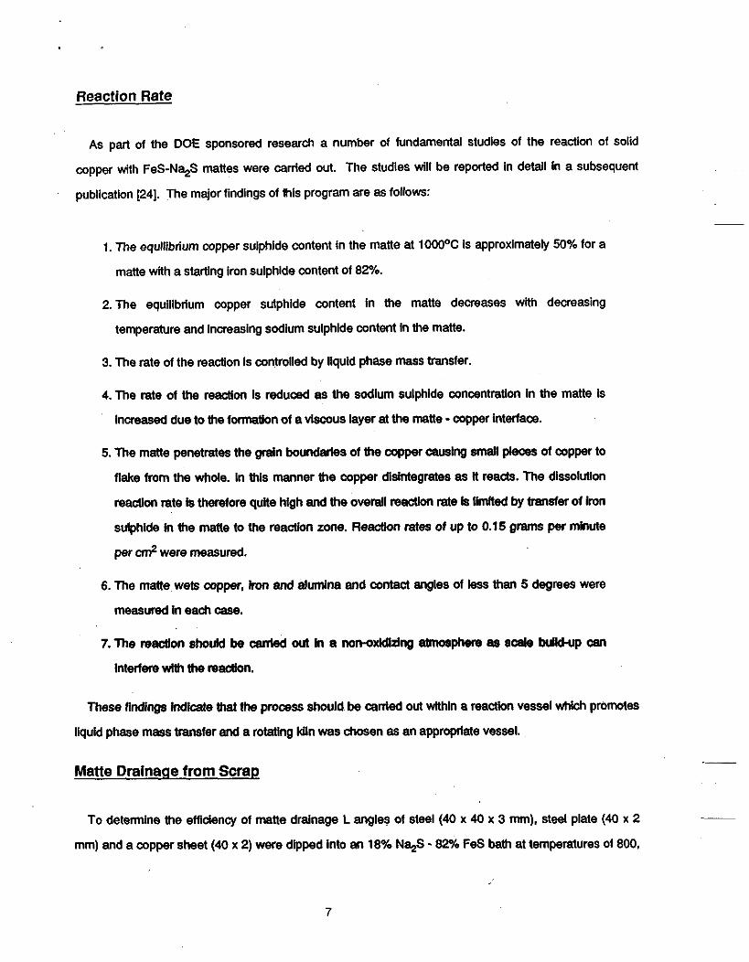
math deawases. In figure 17 Ihe total manechemlstryehangs Is plotted and the tnmsulphldeconienl
apparenlly imases while the sodium sulphide content decreases as a function of time. Due to this
pIoMem trial times were reduced to a maximum of 15 minutes.
__ The major finding from the initial trials was that the process is effective on a larger scale. Copper mixed
with scrap reacts with and becomes part of the liquid matte. in the inltial experiments at 1000°C both a
75-25 and an 82-18 matte formulation gave similar experimental results and both formulations appear to
be appropriate. Trials at higher copper sulphide contents where some of the previous matte had been
-
11

recyded were also successful; although the time to reaction completion was longer. For fresh matte the
reaction was complete by 7 minutes while in trials with 10% initial copper suiphlde, the reaction was
complete within 12 minutes (by visual observation).
Drainage of the matte from the kiln at 1000% was straight forward and only a thin layer of matte was
left on the kiln surface after reaction. This layer could be simply washed out of the kUn after the kiln had
cooled to ambient temperatures. A thin layer of matte could be seen sticking sporadically to the treated
Saap.
It was also clear from the Initial experiments that reoxIdation within the kiln would have to be eliminated
in an industrial process.
Treatment of Electric Motors
A series of experiments was conducted to determine if copper windings could be removed from an
elect& motor in the kiln. The matte pool was formed at 1oooOC and the motor added to the pool. The
added motor was contained In an alumlnum jackel and the copper Wires were plastic coated. A
photograph of the motor before addifion and after addition is gfven In figures 18 and 19. As can be seen
In the figures. the copper was completely separated from the motor. The process is quite smokey as the
plastic covering bums off the wires. but the process is effective. Typical matte chemlshy changes are
given In figure 20. In these trials dnce the motor is completely immersed there is no oxldation pmMem
and all copper can be accounted for by matte chemistry.
Trials at Lower Temperatures
wem carded out using a matte ChemIsUy of 82% FeS - 1% N e at goooC. As
suggested by the phase diagram, the liquid matte formed a very thick and vlscws pod. Upon dissolution
of the oopper, the matte Mdked and coated the walls of the kiln. It w& impossible to draln the matte from
the kiln under these conditions. Experiments using a matte of chemistry 75% FeS - 25% N e were also
i
carrled out wilh similar results; although. in this case some of the matte could be dralned from the Mln. in __
both cases a large quantity of matte was left sticking to the scrap making operation at 9oooC impractical.
12

Matte Drainage From Scrap
To determine the effect of the matte left sticking to the scrap a Mal was run at 1000°C using the 82%
FeS - 18% Na$ matte where 3.4 kg of copper were added to kiln after It contained 80 kg of scrap.
Subsequently, the scrap divided into 15 kg segments. A sample of the treated scrap, In this case ail of the
initial scrap was cut and sized iron rod of known composition, was then remelted and samples chemically
analysed fw copper and sulphur contents.
The inltial copper content of the selected scrap was approximately 0.04% and the Rnai content was
approximately 0.05% indicating that the copper contaminated scrap had been successfully treated by the
process. if the process had been unsuccessful the copper content after remelt would have reached
4.12%. In all cases after treatment no significant copper lncfease could be measured upon remelting
treated scrap.
me sulphur content of the remelted scrap Increased from 0.043% to 0.159%. Thus, the amount of
matte stiddng to the scrap is sufficient to slgniflcantly lnaease the remelted scrap sulphur content 15 Kg
of scrap was remelted in this test therefore 17.4 grams of sulphur or approximately 47 grams of matte
remained sHddng to the scrap. If the matte contained 8% this would be the equivalent of
approximately 2 9 g of copper which m i d only ralse the copper content of the scrap by 0.02 % which is
within the error of chemical analysis and afi of the copper content change In the scrap can be expitlined
solely by the amount of matte sticking to the surface of the scrap.
A second batch of the treated scrap was washed with tap water at room temperature before remelting.
chemical analysis of the remelted scrap revealed no apparent ch8nge in copper Went but the sulphur
content Inmased from 0.043% lo 0.091%. In Utls case apptuximatdy 20 grams of matte was lett sticking
tothe 15 kg of scrap aflertreahent. Thus a water flushing oflhe scrap can reduce the m n t of matte
sticking to the s a a p by at least a factor of two. Agaln If the matte contained 8% Cu.$ there would be
approximately 1.2 g of copper which could only Increase the copper content of the scrap by 0.008% which
is within lhe accuracy of chemical analysis. ___
The third batch of treated s a a p was placed Into a hot (98OC) 8% HCI solution for thirty minutes. Upon
remelting no difference In copper content could be measured and the sulphur content increased by only
0.01% indicating only 4 g of matte remained sticking to the scrap. Thus the sulphur pickup problem can
-
13

be minimized by treatment with a hot add solution.
The process has been proven to be technically feasible; however, for the scrap to be directly hot
charged into an electtic fumace alter treatment some desuiphurization of the melt would be necessary
due to excessive sulphur pickup from the small amount of matte left sticking to the scrap. If the swap was
treated off-slte f” a steelmaker. then, the treated scrap could be washed in a hot acid solution to
completely remove the matte from the scrap surface.
Thk process la more altractive for large swap pieces which have a large volume to surface area ratio.
Due to the large surface area of tumlngs. elc., k would be diMcult to effectively separate the scrap from
the matte wt~en treating this matetial.
It is possible to enhance matte drainage by Increasing the drainage temperature. in these experiments
the hot zone was small and drainage was carried out Mhin a cold zone in the rotary wkr. Therefore, k is
posalMe that the residual matte pmblem will be less once the Mln design is optimized. For example, in our
leboratocy testa the amounl of matte left on the dip samples wss indgniflcant; therefore It may be possible
toaftect a lage seperation of the matte from the treated scrap in practice.
Conclusions
The pmc988 Is ViaMe and technlcelly feasible Il canled out in a nonoxidizing environment It is possible
to effecthdy m v e copper from solid steel saap and, Wnh an add wash, to completely remove the
minimal a“t of matte WMCh remains sticking to the saap.
uedricel motors can be effecliveiy treated using the process.
Acknowledaements
Initial studies of the decopperlration of solid scrap were funded by the member companies of the __
Center for Iron and SteeimaMng Research at Cmegie Melion University. The larger scale trials and
much d the bask research related to the process was funded by the Depatiment of Energy with
cosponsorship by the center for Metals Produdion, The David Joseph Company. and Consolidated
Natural Qas Senitx Companu. Qene Eckhardl of the DOE was a major driving force in the project adding
__
14

technical advice, management and encouragement at the appropriate times.
The project could not have continued without the support of the USX Corporation, which allowed us
access to their pilot facility, and, the AIS1 Direct Steelmaking Team who arranged for vital power and gas
connections and helped us keep a perspective on the task. In particular we would like to acknowledge the
aid of Dr. A. Rathbone and J. Zaranak of USX and Egii Aukrust and Ken Downing of the AISI. ~
Much of the work briefly reported here Is due to the efforts of ltaru Jimbo, Bahri Ozturk, Yuting Zhang
and Ufei Uao of the Center for Iron and Steel Research at Camegie Melion University. Their efforts are
greatly appreciated.
This is a Center for Iron and Steel Research publication.
References
1. Residual and Unsrw3fled Elements In Steel, A. S. Melllli and E. (3. Nisbet, editors, ASTM.
2.1. Jimbo. M. S. Sulsky and R. J. F N d " Iron and Steelmaker, August 1988, Vol. 15, No. 8.
3. M. H. Burden, G. D. Funnell, A. (3. Whitaker and J. M. Young: "Investlgatlon of Surface Cracking Experienced at the Round Oak Steel Works", lntematbnal Conferertsa on the Casting and SolMilication of Metals. The Metals Soclety, London, 1979, pp279 - 289.
4. Manfred M. Won: "Fine Intergranular Surface Cracks In Bloom Casting', Tmns ISIJ, Vol. 24,
5. Roberi J. Christoffel and Alan J. Silva: *Embtittlement of a Copper Containing Weld Metal",
1989.
p20-23.
1984. pp351 - 358. Residual and Unspecified Elements In Steel. ASTM S* 1042. A. S. Melllli and E. G. Nlsbet, Eds.. Amerlcan Society for Testing and Materials. Philadelphia, 1989, pp232 - 242.
6. D. Shaddeton: British Welding Joumal, Vol. 14. Nov. 1967, pp592 - 597.
7. Richard L Bodnar, Bruce L Bramfftt and Raymond F. Cappellink The Influence of ResMual Copper In Annealed and Postweld Heal Treated 2-1/4Cr - 1Mo Steel." , Residual and Unspedfied Elements In Steel, ASTM STP 1042. A. S. Mellln and E. Q. Nkbet. E&., American Society for Testing and Materials. Philadelphia, 1989, pp202 - 231.
8.J. A. McN1chd:"Some Aspects of the Effect of Copper In Cast Iron and Steel", The Australian Engineer, October 7,1953. pp54 - 60.
9.0. Kubaschewski: Iron-Binary Phase Diagram, Springer-Veriag, 1982. p35.
10. L 8. Well: Joumal of the Iron and Steel Institute, 1929. Vol. 119. pp501 - 547.
11. D. A Meiford: "Surface Hot Shortness In Mild Steel", Journal of the Iron and Steel Institute,
12. A. D. Nicholson and J. D. Murray: "Surface Hot Shortness In Low Carbon Steel". Joumal of
13. D. A. Melford: "Influence of Antimony and Arsenic on Surface Hot Shortness in Copper
1962, Vol 200, pp290 - 299.
the iron and Steel Institute, 1965, Vol. 203. pp1007 - 1018
15

Containing Mild Steels", Journal of the Iron And Steel Institute, 1966, Vol. 204, pp495 - 496.
14. W. J. M. Salter: Journal of Me Iron and Steel institute, 1966. Vol204, pp478 - 488.
15. R. Rosegger: Radex Rdsch., 1964, No. 5. ~277.
16. K. G. Speith and A. Bungeroth: Stahl und Eisen. 84, 1964, p1297.
17. V. G. Leak and M. Fine: Bureau of Mines Report of Investigation 7809.
18. J. Peace and D. Engledow: "Developments of Scrap Benefidatlon by the British Steel
19. D. A. Pflaum: "Residual Problems and the Scrap Industly". Residual and Unspecified
20. R. R. Brown and F. E. Block: U.S. Bureau of Mines, Rep. Invest. No. 7218. 1968. p 15
21. G. W. Elyer, W. L. Hunter and C. E. Amantrout: US. Bureau of Mines, Rep. Invest. No. 7210,1968, p 17.
22.A. W. Cramb and A. J. Fruehan: "Recent Progress on Ferrous Scmp Pretreatment". Second International Symposium: Recycling of Metals and Engineered Materials, Ed. J. van Unden, D. L. Stewatl and Y. Sahal TMS, 1990, p 3 - 19.
Corparation", lronmaking and Steelmaking, 1987, Vo1.14, No.5, pp248 - 252
Elements In Steel, ASTM STP 1042.1989, pp l l - 25.
23. J. F. Jordan: US Patent 2,512,578. June 20, 1950.
24. Y. Bang, A. W. C m b and R. J. FNehan: 'Fundamental Studles Of the Reaction Of Solid Copper with Iron Sulphide - Sodlum Sulphide Mattes", In preparation.
25. R. J. SchmHt: 'Automotive Shredder Residue - The Problem and Potential Solutions", Second lntematlonal Symposlum: Recycling of Metals and Englneered MatetiaIs", Ed. J. van Unden, D. L Stewart and Y. Sahai. TMS, 1990, p 315 - 332.
Table I: Ladle Processes for Copper
Process Comments
Lead Extraction
Vacuum Distillation
Sulphlde Slagging
Low dlsMbution ratio, high amounts of lead.
Low surface to volume ratlo, low volatliization
rate
Low distribution ratio, long reaction times,
carbon saturation .of melt prefened.
16

Table I[: Processes for Copper Removal from Solid ScrapIzl
Process Comments
Physical Separation Labor intensive
Preferenfal Meltlng High fuel cost, metal loss and refractory wear
Matte Treatment High fuel cost.
Acid Treatment Dlspsal Problem?
Table 111: Decrease In Average Copper Values Due to Scrap Preparatlon, After P f lau~n~~~]
IYP?
Shredded
#1 Heavy Melt
#2 Heavy Melt
Tumings
#2 Bundles
Before
023
After
0.16
0.24 0.19
0.46 0.37
0.29 0.18
6.51 0.42
17

Figure 1: Phase O @ m of Fe-Cu
18

Na2S-FeS
Figure 2 Phase Dlagram of F e S - N g system.
19

...
20

1 l a 800 900 1000
Temperature of sulfides melt ("C)
flgum 4: Matte Adherence Tdal for Steel L Angle.
I.
21

10
5 -
e .
-
l a
- Flgure 5: Mane Adherence T M for Meel Plate.
22

23

exhaust
fo(dralnage rf- cylinder small holes gas stalnless ,steel ring ,of the kiln
exhaust
I 4"
dralnage of I ' 'L burner matte-
Y Contalnar
Flgure 7: Schematic of the lntemal Klln Configuration
!
24

stainless steel ring
Matte 7
I /
flgum 8 SchemaUc of (A) operatkn KIln Posltlon and (8) Mabrage Kiln POSltion
25

. natural gas
rpm-1 rpm-5 rpm-10
Note: @ The 1st sample. Same as others.
26

14.-
.
5 10 15 20 25 30 35 %(mill.)
. . .
27

12.5-
1 0 -
7 . 5 - .
5 -.
2.5..
% N%S
Flgure 12: VdaUon ol Sodhnn Sulphlde in Matte Ddng the lnltial Tdab
28
. . .,

60- % EeS
40.-
20-
Figure 11: Varlatlonof Imn sulphide h Mane Dwtngthe InitlalTrllllS
-
29

10
30

7.5.'
5
2.5. .
Flgure 14: VeuWionot Capper Sulphide Content fora Matte with a Hlghw M n g copper SUPW -
-.
31

100
80
60
weight 46 40
20
32

I * 5 10 15 20 25 30 35 - (&I
Flgure 16: Varlatlon of Cbpper SulpNde Content M n g a76- 25 MatteTW.
c
33
Flgum II: Variation In Matte ChedsbleS du(ng a 76 - 25 Matte Tdal
34

Figure 18: ElecMc Motor before Additbn to Kiln
35

flgure 19 ueclrlc Motor AiW Addition to Kiln
36

Weight % ai. 2 0 ; ;
% N%S - - “curs - -
Figure 20: Matte ChemlstrY Changes duting Addltkn of Eledrlo Motor
.I
37

38

RECENT PROGRESS ON FERROUS SCRAP PRETREATMENT
Alan W. Cramb and Richard J. Fruehan Department of Materials Science and Metallurgical Engineering
Carnegie Meilon University Pittsburgh, PA 15213
The potential build-up of residual elements in steel is a cause for concern within both the steel and the scrap industries. High levels of elements such as copper, nickel, molybdenum, tin and chromium are thought to be deleterious to product consistency and have aiso been shown to cause problems during casting and subsequent processingjll The absolute level at which a residual element becomes deleterious to product quality is dependent upon the application; however, it seems reasonable to assume that, at some time in the future, prudent background levels of residual elements will be exceeded, leading to scrap sotling or pretreatment as a routine operation before charging into an electric arc furnace.
in addition to the residual problem, the growth in recycled automotive galvanized sheet scrap has resulted in increasing zinc content in the exhaust dusts of the steelmaking furnaces. This dust is considered hazardous by the EPA and disposal is expensive as it is classified as a hazardous waste. Thus zinc must also be removed from scrap before it is charged into the steelmaking furnace.
The purpose of this article wiii be to review scrap pretreatment for the removal of copper and zinc from scrap. Some recent efforts at Camegie Mellon University to develop a method of scrap pretreatment which would allow solid copper to be separated from solid scrap will be highlighted.
39

The Cower Problem
me United States has a tremendous ferrous scrap surplus. To produce steel from scrap takes less than one third of the energy that it does when starting with ore. In addition, many of the major environmental problems are eliminated, In particular those assodated with coke making. However, much of the scrap cannot be used becam9 it contains elements, such as copper and zinc, which are detrimental to the steelmaking process or the propelties of the Steel produced. If these unwanted elements can be removed, considerably more steel can be recycled and other environmental problems related to steelmaking reduced.
Backwound The copper residual problem is well recognized in both the solidification and deformation processing of liquid steel. Gross defects have been found during the casting, rolling and welding of steels with significant copper re~iduals[~-~1, while variations in product properties have been correlated to copper variations in the aiioy[61.
Generally copper residual contents are limited to less than 0.35%' in most alloy steels with the exception of weathering steels (0.5%) and steels exposed to nuclear radiation (O.lo/o); however, copper contents of less than 0.25% have been shown to cause fine intergranular cracks on bloom castingd31. The maximum allowable copper levels for various grades of steel are given In Table I. In general the copper levels in steels produced by integrated producers of flat products are controlled to lower levels than those produced via electric arc furnaces.
Table I: Maximum Allowable Copper Levels
Application
Deep Drawing Steel 0.06%
Tin Plate (critical)
Drawing Quality
O.O6?h
0.10%
Steel Forgings 0.35%
Irradiated Steels 0.10%
Bar Products 0.35%
Casting and roiling defects are caused by embrittlement due to the formation of a liquid copper film which forms when the iron is preferentially oxidized during the formation of ~cale[~sfl. This preferential oxidation causes an enrichment in copper and other residuals such as nickel, tin and antimony in the grain boundaries. Copper rich phases found in cracks on bloom surfaces at Round Oak Steel Works in England were found to contain 85% Cu. 5% Fe, 5%Sn, 4% Ni and 1% Sb which would be molten
__
~
'supplementary requirement SI of ASTM Specification for Steel Forgings, General Requiremenk (A 788)
40

below 1 100°C (Figure l[al) and give rise to classical 'hot shortness' due to penetration of the liquid film along the grain boundary. This phenomenon of liquid copper film embrittlement of steels in an oxidizing atmosphere is well documented, was originally proposed by F'feiligl and was discussed by a number of authors during the sixtiesilo - l31. One suggested method of eliminating this defect is to ensure that a solid intermetallic compound of copper and nickel is formed by ensuring that the copper to nickel ratio in the steel is 3 : 1 or largedg1; however, at higher copper levels (0.35%) substantial quantities of nickel (0.12%) would have to be intentionally added to ensure avoidance of the defect. A listing of the factors which can favorably affect the hot workability of copper containing steels is given in Table JI.
Flgure 1: Phase Diagram of FoCu systeme.
Table JI: Factors Favorably Affectlng the Hot Workability of Copper Comalnlng Steels, after 8. F. Glasgal, [l]
Low Copper Residuals
Fast Heating Rates
Reduced Time at Temperature
Limited Scale Formation
Nickel:Copper Ratio greater than 1:3
Another copper induced crack which is very common in continuously cast slabs and blooms is the star crack. This crack is caused by localized surface concentrations of copper which are due to wear of the
41

continuous casting mold. Again the cracks are caused by thin liquid copper films which penetrate the grain boundaries leading to embrittlement. This problem is generally countered by mating the molds with a more abrasive resistant material such as chromium or n i ~ k e l [ ~ ~ * ~ ~ I .
Copper provides a modest degree of solid solution strengthening in ferrite and, as reviewed by Bodnar et al[6i, can lead to irradiation and stress relief embrittlement; to reductions in hot tensile strength and aeep rupture ductility: and, lu temper embrittlement. In addition Bodnar et al. have shown that variations in copper content can lead to gross variations in the yield strength of tubesheet f o r g i n g ~ ~ ~ l
Due to the growing body of evidence which suggests that copper levels in steels must be controlled and, due to concerns that the background copper levels in steei scrap are increasing due to increased recycling and decreased production of home scrap, there have been numerous studies over the last forty years to determine an efficient method of copper removal from steel. These studies are based on either the treatment of liquid steel or the treatment of solid scrap.
Treatment of Liquid Steel A review of the most recent techniques for copper removal from liquid steel was carried out by Jimbo et alIc61 and a commentary on liquid and solid techniques is given in Table Ill. Sulphide slagging has been the most extensively researched method of removing copper from liquid steel. This process, originated by Jordanl’n in 1950, is based upon the following reaction:
2 9 + FeS = Cu2S +& [I 1
At temperatures above 6OOOC copper sulphide is more stable than iron sulphide: therefore, solid copper when in contact with a matte containing iron sulphide forms copper sulphide and precipitates iron. In the actual process an Ionic exchange reaction occurs:
- Cu + Fe2+ = 2 Cu+ +B 121
where electrons are transferred from the copper to the Inn and the rate of reaction will be determined by liquid phase mass transport of copper in the liquid steel. Sudium sulphide Is normally added to iron sulphide to lower the melting polnt and the viscosity of the matte[I*I and carban is added to the liquid steel to increase the activity coefficient of copper in the liquid steelli81. Jimbo et al[I6] have shown that the optimum copper distribution ratio for FeS-Na2S mattes at 16OO0C is approximately 20. Thus, to reduce liquid steel copper content from 0.3% to O.l%, 100 kg of matte per 1000 kg of metal would be required. At current prices of Iron and sodium sulphide this would make the process prohibitively expensive.
Solid Scrap Treatment __ 90% of the copper present in scrap exists primarily as pure copper in the form of wire or platted material. This has lead to physical separation as a means of reducing the overall copper content of scrap and to practices of raw material segregation being widespread in the scrap ind~s t ry l~ ,~~1. In Table I V typical copper levels and standard deviations are given for various scrap types (after fflaum [21]) and, in Table V, the benefits of a scrap sorting program are indicated. Unfortunately, physical separation and sorting of scrap is time consuming, labor intensive, expensive and cannot reduce the overall copper contents to less than 0.05%; a level necessary for the production of flat products via a
~
42

Table m: Processes for Copper Removal from Scrap['I
Process Comments
Physical Separation Labor intensive
Lead Extraction
Preferential Melting
Low distribution ratio, high amounts of lead.
High fuel cost, metal loss and refractory wear
Vacuum Distillation
Sulphide Slagging
Low surface to volume ratio, low volatilization rate
Low distribution ratio, long reaction times, carbon saturation of melt Dreferred.
Matte Treatment High fuel cost.
Acid Treatment Disposal Problem?
steelmaking route that indudes scrap remelting.
Table N: Average Copper Contents, after Pflaum [21]
Type Average Standard Error
#l Bundles 0.021 0.012
Bushelings 0.032 0.014
#2 Steel 0.236 0.115
#I Steel 0.117 0.005
Turnings 0.063 0.057
Pit Scrap 0.074 0.071
Home Scrap 0.071 0.008
Laboratory Studies
An alternate to scrap sorting was invented by R. J. Fruehan, who combined the preferential melting
43
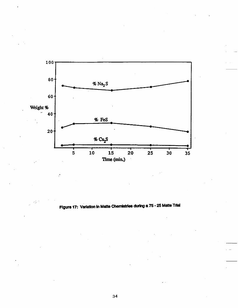
Table V: Decrease in Average Copper Values Due to Scrap Pteparatlon, After Pflaum [21]
mE
Shredded
Before
0.23
After - 0.16
#1 Heavy Melt 0.24 0.19
#2 Heavy Melt 0.46 0.37
Turnings 0.29 0.18
#2 Bundles 0.51 0.42
technique with Sulphide slagging to develop a new technique capable of the removal of solid copper from solid scrap at temperatures lower than the melting point of copper (1083OC). Fruehan’s process, which operates at loOO°C or below, is based on an analysis of the chemistry of the system. For example, the equilibrium constant of equation 1 is as follows:
and,
‘FI “ C G
%,’.FlS K =
“Fe ‘Cu$ AGO = u p [ - - .C?“Fd R T ]
where A G O is the standard free energy of reaction 1. In Fruehan’s process solid iron is precipitated upon reaction.
In the above equation A G O is negative (the reaction is spontaneous), and the value for K is approximately 2 at 1000°CI‘61. Thus to maximize the amount of copper in the matte one needs a law starting activity of copper sulphide in the matte, a high iron sulphide activity in the matte and a high copper activity. The activity of solid iron is 1.
Thus the starling matte composition should be high in iron sulphide and low in copper sulphide. In addition the matte must be liquid and fluid at treatment temperatures, and sodium sulphide is normally added as the matte‘s liquidus can be lowered to 700°C by such additionstz] (Figure 2). Sodium sulphide also decreases the activity of copper sulphide in the matte, thus improving the thermodynamics of copper removal. A normal mane starting composition is 82% FeS - 18% Naps.
44

Na2S-FeS
Flgure 2: Phase Diagram of Fe-SNa,S system.
MelUng scrap puts copper into solution in liquid iron and significantly reduces its activity when referred to pure liquid copper. Even in carbon saturated iron, where the copper activity coefficient is high, the activity of copper in solution in liquid iron is reduced by a factor of 25 - 50 as compared with pure copper. Due to the low copper activity in the meit the partition of copper between the matte and the liquid steel is significantly lowered and trials at the Bureau of in a 1.5 ton pilot operation could only remove 40% of the copper from the metal using 200 Ib of an FeS-Na,S mixture per ton of carbon saturated iron. The activity of copper as a pure solid is by definition unity. Thus it is more thermodynamically feasible to remove solid copper from solid scrap than to remove copper from scrap which has been remelted.
The iron sulphide - sodium sulphide matte reacts with solid copper, displaces solid iron and forms a iron sulphide - sodium sulphide - copper sulphide matte which is liquid and fluid at temperature (Figure 3). This matte can then be drained from the scrap.
Initial trials of the concept were carried out by Jimbo et alj161 on a laboratory scale at Camegie Mellon University using a matte containing 19 to 25% Na,S. Simulated scrap consisting of pieces of iron and copper were treated in a rotating crucible with FeS-Na,S fluxes (Figure 4). Approximately 100 grams of simulated scrap containing from 0.4% to 1% Cu was treated. over 90% of the copper could be removed at 1000 C and nearly 80% at 800 C. Initial trials indicated that only 4 kg of matte per metric ton of scrap would be necessary to treat steel containing up to 1% copper.
Process Benefits
Due to the success of the Small scale tests in proving that Fruehan’s concept had potential, a detailed comparison of solid and liquid scrap treatment was made. The advantages of the solid scrap treatment
45

Figure 3 Phase Diagram of the FeS-Na,S-Cu,S system.
thermocouplc rotary shilfl
\
Figure 4: Schematic of Rotary Mlxer Used in inltlal Tests, after Jlmboq6
process were as follows:
.-.Lower Matte Weight. To reduce Fpper from 0.4 to 0.1% in the scrap less than 10 kg of matte would be thermodynamically necessary via the solid process, while 120 - 200 kg
46

would be needed for liquid processing.
One Step Process. In the liquid treatment the slag would have to be removed, the matte added and the steel carburized before treatment and decarburized after treatment. In the solid process the matte would mixed with th8 saap, and, after reaction, drained.
.Lower Na,S Loss. Evaporation losses from the matte are much lower at lower temperatures.
Increased Matte Copper Content. Matte copper content could be as high as 30% in the solid process: therefore, recovery of copper from the matte may be economically feasible.
Decreased Resulphurization of Metal. In the liquid treatment there will be a significant sulphur pick-up by the liquid steel which would necessitate extensive desulphurization after processing. In the solid scrap process sulphur pick-up would be determined by the amount of matte which did not drain from the scrap.
Process Flexibiliiy, The solid scrap treatment process could be a stand alone unit off-site from the remelter or an onsite unit supplying preheated low copper saap to an electric arc furnace. The liquid process would require an advanced ladle metallurgy statio!, equipped with reheat, slag skimming and injection facilities. The solid treatment would not affect process cycle time after melting,' while the liquld treatment stage would have a considerable impact on productivity.
In addition, an economlc assessment of the process was made which suggested that the energy cost of treatment would be approximately $5.00 per ton, and the reagent cost approximately $2.00 per ton. If the hot scrap Is charged directly into the electric furnace there would be a decrease in electrical energy of approximately 250 kwh\ton and corresponding decreases in heat time and refractory wear which should lead to increased productivity and lower operating costs. Although it is difficult to exactly calculate total cost savings due to variations in raw material prices, we estimate that it may be possible, if there is a $40.00 per ton differential between high copper scrap and low copper scrap, that cost savings of approximately $20.00 per ton for direct electric arc furnace charging and $ 10.00 per ton.for a stand alone processor may be possible.
Practical Concerns
The initial small scale experimentation resulted in a number of questions concerning this new process:
What was the rate controlling step in the reaction?
Would the matte spread and wet scrap?
Could the matte be effectively drained from the scrap?
Could the process be carried out in air?
Would it be possible to treat electrical motors with this process?
To answer the above questions a number of experiments were carried out before large scale, industrial tests were initiated.
1. Rate Controlling Step.
It was assumed that liquid phase mass transfer would be the rate controlling step in the reaction. Thus, a rotating cylinder experiment was attempted under conditions where the mass transfer was well
47

documented. Typical experimental results from the work Of Y. Zhang' are given in Figures 5 and 6. where the increase of matte copper sulphide WncentratiOn can be seen as a function of time and rotation speed (Figure 4) with the attendant decreases of sodium sulphide and iron sulphide (Figure 5). At higher rotation speeds the reaction was found to be controlled by mass transfer; however, at low rotation speeds the matte formed a viscous layer which impeded mass transfer. Thus it is important to carry out the matte process in an environment, such as rotating kiln, which stimulates matte movement.
4 0
3 0
2 0
1 0
0
t Oq'
I-
F y l * I , I I I ,
I I I , I 0 15 30 45 6 0 75 9 0 105 120
Time (min)
Flgure 5: Concentratlon of Copper Suiphlde In Matte as a Function of T" and Rotation Speed.
2. Matte wettabiiity.
Experiments were carried out using an X-Ray Radiographic Technique to determine the contact angle between the matte and iron, copper and an alumina refractory. The results of this study indicated that the matte wet and spread upon iron, copper and the alumina refractory. Contact angles in all experiments were less than 5 degrees.
3. Matte Drainage.
To determine the efficiency of matte drainage L angles of steel (40 x 40 x 3 mm), steel plate (40 x 2 mm) and a copper sheet (40 x 2) were dipped into an 18% Na,S - 82% FeS bath at temperatures of 800, 900 and 1000 C. The samples were emersed for 3 to 5 minutes before being withdrawn from the bath and air cooled.
q. Zhang. A. W. Cramb. and R. J. Fwhan: unpublished research. CISR. Camegie Mellon University. 1990
4 8

s o
6 0
c’ u a 3 4 0 - E
2 0
0 0 2 0 4 0 6 0 so 100 120
Time(min) Figure 6: Concentratlon of Sodium Sulphide and Iron Sulphide in Matte as a Functlon of Time and Rotation Speed.
The copper sheet was completely dissolved at all temperatures. Results of the drainage experiments are given in Figures 7 and 8, where the AM% is the weight gain upon removal from the matte. In both cases the amunt of matte adhering to the scrap was minimal at 1000°C; however. significant amounts of matte remained attached to the scrap at lower temperatures.
4. Process Feasibility in Air.
The above dip tests were carried out in air with no apparent deleterious effects; however, the time at temperature was small. Other experiments, carried out over longer time periods, indicated that if the copper was allowed to significantly oxidize, the process efficiency greatly decreased. In addition, if the iron was allowed to significantly oxidize, iron oxide would be picked up in the matte.
5. Removal of Copper from Electrical Motors.
To determine the efficiency of drainage from a copper wound motor, a large bath of matte (40 kg) was melted in an induction furnace using a carbon crucible. The motor was lowered into the matte and slowly rotated. The matte temperature was 1000 C during the experiment. Initially there was a large quantity of smoke as the plastic coverings. etc.. on the copper windings burned off. The motor was rotated for 20 minutes and then removed. All copper which was emersed in the matte was removed from the motor.
Larger Scale Trials
In view of the process potential larger scale experiments were proposed to and accepted by the DOEz4. A rotary kiln was purchased from CORECO, and set-up in the pilot facility of USX Corporation
49

15
10
Q 5 -
Figure 7: Matte Adherence Trial for Steel L Angle.
-
4B
-
-
I a
20
a 15 3
10
5 -
0
-
I 0

\ . . . . - 'INDIRECT HEATING '.
Figure 9: A Schematlc of the CORECO Rotary Kiln.
been treated. Copper tubing and wire have been used to simulate the solid copper content of scrap. The process was operated at 1000°C and up to 4 kg of copper was removed from solid scrap in less than 10 minutes. At 1000°C there have been no problems in draining the matte from the kiln and copper removal efficiencies are approximately 90%. An example of the increase In copper sulphide content of the matte during a large scale trial is given in Figure 10. The fast rate of copper pick-up can be seen (4 kg of copper in less than 10 minutes). The copper sulphide content decreases as a function of time due to increasing matte FeO content as a consequence of oxidation of the scrap; therefore, it is best to carry out these experiments in a nonoxidizing atmosphere.
The Zinc Problem
The melting point of zinc under 1 atmosphere pressure Is 419.58OC and its boiling point is 907%. Thus, in any steelmaking process where temperatures can rise to 16OO0C, zinc will vaporize, potentially oxidize and be found in the exhaust dust of the process. Electric furnace dusts are considered hazardous by the Environmental Protection A g e n ~ y ~ * ~ ~ ~ ~ ] , due to the leachability of the toxic tramp elements of lead, cadmium and chromium and disposal of this dust is expensive. This has lead to numerous attempts to remove the zinc from the scrap before it is charged into the steelmaking
in order to produce a material which can be more easily and profitably recycled.
The problem is being exacerbated by the growth in the amount of automotive galvanized sheet steel scrap which was estimatedIz51 to increase to 1.4 million net tons by 1990 by CMP. Automotive scrap is estimated to be only 10% of the galvanized scrap production, with the remainder joining the scrap problem in future years due to obsolescence of the galvanized part.
51

nmc (min)
Figure IO: Copper Sulphlde Valfatlon In Large Scale KIIn Experiments.
Thus it is of great interest to develop saap pretreatment proceses which will cause separation of the zinc from the scrap before charging into the vessel. Three basic methods of zinc removal have been suggested:
Chemical Treatment
Electrochemical Treatment
Thermal Treatment
A number of the processes are combined chemical and electrochemical where the zinc is dissolved into an acidic or basic solution and electrochemistry is used to accelerate this p r ~ c e s s ~ ~ ~ ~ l . A benefit of the chemical processes is that the zinc can be recovered from the liquor.
Thermal treatment methods indude plasma processing, induction heating, processing in conventional steelmaking furnaces and high temperature scrap
Plasma p r o c e ~ s e s [ ~ ~ ~ ~ 1 pass a gas through an electric arc between 60 electrodes to produce an ionized gas which forms the plasma. Temperatures range from 3000 to 50OO0C. Major problems in this technology are related to operational cost but the process is feasible[26].
Other thermal treatment methods include induction heating[=], controlled addition to conventional steelmaking to ensure that the average dust content is kept at tolerable levels. and scrap preheating. Of these methods, scrap preheating in a rotary kiln seems advantageous as the energy cost can be alleviated by direct charging into an electric furnace. In fact, the process outlined earlier for copper removal, as it operates above the boiling point of zinc could also be developed to remove zinc from scrap if the vaporized zinc were oxidized and the dust
52

Any scrap preheating system which increases the scrap temperature above the boiling point of zinc will result in zinc removal from the scrap; therefore, processes such as the CONSTEEL and KORFS EOF process have the potential to remove zinc from galvanized scraplS1. However, recondensation of zinc in a commercial vessel can cause a sticking problem in the vessel and it is probably best to remove zinc in a process specifically designed for zinc removal where condensation is strictly controlled or the zinc oxidized to a fine dust for ease of collection[sl. For example, Daido steel has a process where zinc is oxidized in a kiln and the scale is removed in a ball mill.
Conclusions
Scrap pretreatments for the separation of copper and zinc from steel scrap may become commercialized in the next few years due to the need to r e d w the copper residuals in melted scrap and to eliminate the furnace dust problem. A number of processes are under development towards this goal and a rotary kiln type of process is technically feasible for both zinc and copper removal from ferrous scrap. A new process, developed at Carnegie Mellon University, allows both scrap preheating and mpper removal. A slmilar type of process could easily be adapted to allow zinc removal as the process temperature is above the boiling point of zinc.
Initial studies of the decopperization of solid scrap were funded by the member companies of the Center for Iron and Steelmaking Research at Camegie Mellon University. The larger scale trials and much of the basic research related to the process was funded by the Department of Energy with cosponsorship by the Center for Metals Production, The David Joseph Company, and Consolidated Natural Gas Service Company.
The project could not have continued without the support of the USX Corporation, who allowed us access to their pilot facility, and, the AIS1 Direct Steelmaking Team who arranged for vital power and gas connections and helped us keep a perspective on the task.
Much of the work briefly reported here is due to the efforts of ltaru Jimbo, Bahri Ozturk, Yuting Zhang and LiFei Liao. Their efforts are greatly appreciated.
References
1. Residual and Unspecified Elements in Steel, A. S. Melilli and E. G. Nisbet, editors, ASTM, 1989.
2. M. H. Burden, G. D. Funnell, A. G. Whitaker and J. M. Young: "Investigation of Surface Cracking Experienced at the Round Oak Steel Works", International Conference on the Casting and Solidification of Metals, The Metals Society, London, 1979, pp279 - 289.
3. Manfred M. Wolf: "Fine Intergranular Surface Cracks in Bloom Casting", Trans ISIJ. Vol.
4. Robert J. Christoffel and Alan J. Silva: "Embrittlement of a Comer Containina Weld
24,1984, pp351- 358.
Metal". Residual and Unspecified Elements In Steel, ASTM STP 1042. A. S. Mekli and E. G. Nisbet. Eds.. American Societv for Testina and Materials. Philadebhia. 1989. - . . pp232 - 242.
5. D. Shackleton: British Welding Journal, VoI. 14, Nov. 1967, pp592 - 597.
6. Richard L. Bodnar, Bruce L. Bramfitt and Raymond F. Cappellini: The Influence of
53

Residual Copper in Annealed and Postweld Heat Treated 2-1/4Cr - 1Mo Steel." , Residual and. Unspecified Elements in Steel, ASTM STP 1042, A. S. Melilli and E. G. Nisbet, Eds., American Society for Testing and Materials, Philadelphia, 1989, pp202 - 231.
7. J. A. McNicho1:"Some Aspects of the Effect of Copper in Cast Iron and Steel", The
8.0. Kubaschewski: Iron-Binary Phase Diagram, Springer-Verlag, 1982, p35. 9. L. B. Pfeil: Journal of the Iron and Steel Institute. 1929, Vol. 119, pp501 - 547.
Australian Engineer, October 7, 1953, pp54 - 60.
lo. D. A Melford: "Surface Hot Shortness in Mild Steel", Journal of the Iron and Steel Institute, 1962, Vol200, pp290 - 299.
11. A. D. Nicholson and J. D. Murray: "Surface Hot Shortness in Low Carbon Steel", Journal of the Iron and Steel Institute. 1965, Vol. 203, pp1007 - 1018
12. D. A. Melford: "Influence of Antimony and Arsenic on Surface Hot Shortness in Copper Containing Mild Steels", Journal of the Iron And Steel Institute. 1966, Vol. 204, pp495 - 496.
13. W. J. M. Salter: Journal of the Iron and Steel Institute, 1966, Vol204, pp478 - 488.
14. R. Rosegger: Radex Rdsch., 1964. No. 5. p277.
15. K. G. Speith and A. Bungeroth: Stahl und Eisen. 84,1964, p1297.
16. I. Jimbo, M. S. Sulsky and R. J. Fruehan: Iron and Steelmaker, August 1988, pp20.23.
17. J. F. Jordan: US Patent 2,512,578. June 20.1950.
18. N. Kopylov and S. Novoselov: Zh. Neorgan Khlm., 9 (8). 1964, p1919.
19. W. Oelsen, E. Schuermann and G. Helnrichs: Archiv fur das Eisenhuttenwessen, 30,
20. J. Peace and D. Engledow: "Developments of Scrap Benefclation by the British Steel
1959, pp649 - 654.
Corporation", lronmaking and Steelmaking, 1987, Vo1.14 , N0.5, pp248 - 252 21. D. A. Pflaum: "Residual Problem and the Scrap Industv. Residual and Unspecified
Elements in Steel, ASTM STP 1042.1989, pp l l - 25.
22. V. G. Leak and M. Fine: Bureau of Mines Report of Investigation 7809.
23. N. Kopylov and S. Novoselev: Zh. Neorgan. Khim., 9(8), 1964, plO42.
24. R. J. Fruehan and A. W. Cramb: "Removal of Copper from Scrap", A proposal to the DOE. December 14.1987.
25. R. J. Fruehan: "Scrap in Iron and Steelmaking", Recycle and Secondary Recovery of -3 Metals P. R. Taylor, H. Y. Sohn and N. Jarrett, eds.. TMS, 1985, pp13 - 34.
26. 0. F. Angeles and Edward F. Petras: 'Dezincing of Galvanized Steel Sheet Scrap" CMP
27. H. 0. Reitere and W. Morth. European Patent No. 73186, March 2, 1983.
28. Belgian Patent No. 892,897, October 19. 1982.
29. J. Frenay, J. Hissel and S. Ferlay: "Recovery of Lead and Zinc from Electric Steelmaking Furnace Dusts by the Cebedeau Process", Recycle and Secondary Recovery of Metals,
30. R. J. Fruehan: "Plasma Processes for Metals Production: A %ping Study", CMP Report
31. T. Knoepke: "Initial Results from the VoestAlpine Plasma Furnace", Iron and Steel
32. J. A. Dalessandro and D. L. McBride: "Superheating Blast Furnace Iron with Channel
Report No. 86-1, May 1986.
TMS 1985, pp195 - 202.
NO. 85-3, 1985.
Engineer, May 1985, pp23 - 26.
54
Induction Furnaces", Iron and Steel Engineer, February 1985, pp29 - 36. 33. Japanese Patent No. 57/85916,1982.
34. J. A. Vallomy: " Continuous Steelmaking Via Electric Furnace, The CONSTEEL
35. J. E. Bonestell and R. Weber: "EOF (Energy Optimization Furnace) Steelmaking ", Iron
36. D. R. MacRae: "Electric Arc Furnace Dust - Disposal, Recycle and Recovery" CMP
Process", AIM€ Electric Furnace Conference, 1984.
and Steel Engineer, October 1985, pp16 - 22.
Report No. 85-2, May 1985.
55

56

ClSR PROGRESS REPORT
REFINING OF COPPER FROM SOLID FERROUS SCRAP
L Llao, Research Associate
A.W. Cramb, Asslstant Professor R.J. Fruehan, Professor
Feb. 2,1989
Introduction
The United States has a great abundance of ferrous scrap and will have a surplus for the
foreseeable future. The American steel industry currently uses more Iron units from scrap than
from ore for the production of steel.' However, scrap often contains detrimental elements which
can not be refined In the normal steelmaking operation. The most troublesome of these
detrimental elements is copper, which has been identified as a major concern of American
steelmakers.' An extensive review of the possible pyrometallurgical refining methods of removing
Cu was carried out3-I' Of ail the proposed methods a sulfide treatment appears to be the most
promising. There are two options for refining of Cu from ferrous scrap. One is the refining of Cu
from liquid ferrous another Is from solid ferrous swap." The required quantity of matte
for removal of Cu from liquid scrap is too large to lead to an economical refining process,
accordingly the refining of Cu from liquid scrap Is not practical.
Reflnlng of Cu from solld scrap
A new concept for copper removal from ferrous scrap Le. a refining of Cu from solid scrap
was developed by R.J. Fmehan." Copper is primarily present in ferrous scrap as pure copper, for
example. wires and plated metals. The themwdynamics of removlng copper before it Is put into
solution in liquid Iron is greatly improved. When the scrap Is melted and the copper is in solution in
iron, its chemical activity is greatly reduced, even when the effect of carbon, which inceases the __
activity coefficient of copper, is taken into account. in another words, if the Cu is not put into
57

solution, the reaction for Cu removal will be more favorable. In addition, the treatment of solid
scrap has other advantages:
(1) It lends itself to some of the scrap preheating technologies currenlly under development;
(2) There is no need for desulfurization, caltxlrization and decarburization processes as is the
case for treatment of scrap which is melted prior to treatment.
Experiments were pertormed using a rotating graphite crucible, simulating a rotating kiln
with a revolution speed of 20, 40, 60 tpm. In these experiments 100 grams of sythetic scrap
containing 0.5 or 1.0% Cu was treated with 8 grams of FeS-Na2S containing 19 to 25% Na,S at
the temperature of 800 'C, 9OO'C, and IOOO'C. The experimental results showed that over 75%
of copper can be removed in duration time of 20 m'nutes. A crude evaluation indicated that to
remove copper level from 0.4 to 0.1% about 10 kg of an 80% FeS-20% Na2S matte per tonne of
scrap is requlred. . .
>! 3
Experlments prior to settlng up a klln
Based on the above experimental results a large scale rotary kiln will be set up for further
pre-pilot experiments for removing Cu from soUd scrap. Prior to setting up the kiln two types of
experiments were planed. The first is a static experiment in a Lindberg horizontal furnace. The
purpose of this experlmenl is lo determine the contact angle and wettability between the sulfide
melt and the sample and to determine It there Is any reaction between the melt and sample at
1OOo'C in an argon or air atmosphere. The second is a wefiability experiment in a Undberg
vertical fumace. In which a metal sample will be insetted into a crucible with sulfide melt in it and
then withdrawn out of it to determine rate of matte dralnage. An electrobalance above the vertical
furnace will be used to determine the change of weight of the sample as a function of time,
temperature and at different FeS : Na2S ratio, at 1OOo'C and under a controlled atmosphere.
Different types of steel e.g. 1008, 4150. 304, 409, 446. 18-8 etc. will be used for the
experiments.
58

To date the static experiment in the horizontal furnace have been completed. Once
Undberg vertical furnace is set up, the experiments to determine matte separation efficiency will
be conducted.
Work to Date
(1) ExPed"
A Lindberg horizontal furnace capable of temperature exceeding 1OOo'C was used for
experiments. The schematic diagram of the furnace that contains a alumina tube is shown in
Figure 1. Inside the furnace tube was put a silica glass tube which is 4 1/2 ' L x 1" D with one end
open and another end close and with a gas inlet and a outlet.
The sample with FeS-Na2S mixture (7525 or 82:18) was placed in the center part of the
silica glass tube ( hot zone about 10 cm long) under an argon or air atmosphere at 1OOo'C for 1,2,
4 and 20 hrs. The sheets of AIS1 1008, AIS1 4150,304,409,446. 18-8 and Cu were used as
sample for experiments. The chemical composition for above steel is shown in Table 1. After the
sample was removed from the silica glass tube and cooled. pictures were taken. Some of those
samples were cut. ground, polished, etched. The samples of 1008 and 4150 were etched in a
7% nital solution while the stainless steel 18-8 was etched in a superpicral etchant solution with
0.5% HCI. Finally the pollshed, etched samples were photographed using SEM to obselve the
microstmcture of the transverse section of the sheet and to determine the depth of attack.
(2) Results and Discusskn
Alter the sample was placed inside the glass tube for 10-15 minutes, the sulfides on the
sample began to met no matter what FeS:Na$ ratio was used and run all over the surface of the
sample. There was no a droplet formation and accordingly no contact angle between melted
sulfides and sample could be measured, as shown in Figures 2 and 3. The contact angle is very
low ( c 5'). The depth of the layer of sulfides which melted on the sample was about O.lmm . In an uncontrolled atmosphere (open air) all the steel samples were oxidized with different
extent regardless of whether the melted sulfide mixture was 75% FeS:25% Na,S or 82% FeS:
59

18% Na2S. The AIS1 4150 steel ( containing Cf, Ni. and Moc 1% ) was oxdized most heavily,
followed by AIS1 1008 ( low carbon steel ) and finally by 18-8 stainless steel. Figures 4 to 9 show
that the unpolished and unetched photographs of the sample and the flake for 4150, 1008, and
18-8 at 1OOO'C and open air. The longer the time, the deeper the depth attacked, but within 1 hr
the sample was slightly oxdired for 4150 & 1008 samples. After 2 or 4 hrs both the 4150 and
1008 were oxidized heavily. The 4150 was oxidized so badly that It was totally encased in the
scale with 0.12"thickness. as shown in Figure 10. In contrast with the uncontrolled atmosphere.
in argon atmosphere, no matter whether 4150,1008 or Stainless steel (e.g. 18-8, 304, 409,446)
samples were used, none of the steel samples were oxidized to any extent as shown in Figure
1 I .12 and 13. lt was noted that a copper sample was totally oxidized and formed a melted mixture
of copper oxide and copper sulfides which was brittle. but the copper was not oxidized under
argon atmospher. as shown in Figure 14 and 15.
~
The analysis of the SEM photographs of the unpolished sulfaca reveals essentially the same
results as the above Figures. At the uncontrolled atmosphere in all cases of the steel, the
sulfaces were oxidlzed so badly that pieces of the scale flaked off. Each of these samples was
photographed along with the corresponding flakes. These photographs confirmed the analysis
of the visual inspection.
Figures 16 to 21 show that the pholographs of the transveme section of each of the samples
polished and etched for 4150,1008 and 18-8. The polished and etched samples might not show
a twe depth of attack at air atmpsphere. This was due to the fad that 1 was impossible to polish the
samples and retain any of the scale layer. The photographs were analyzed for depth of attack and
the results are shown In Table 2. The results show that under an argon atmosphere the surface of
the steel samples will not be attacked, while at open air attacked to different extent. The worst
case was the 4150 followed by 1008. With the few samples that were attacked under argon __
atmosphere, if could have been because the argon tank ran out before samples were removed
from the furnace. Unfortunately lhese results are not very amfate due to the large amount of
flaking of t:j3 scale that occured.
-
60

Other experiments were canied out for samples of 304,409, and 446 under argon or air
atmosphere at 1OOo'C for 1, 2,4 even 20 hrs in the fumace. All of them were completely wet and
no obious attack could be found on the surface of the sample. Thus the higher chromium
containing steel appear to be more resistant to both oxidation and attack by the sulfide matte, and
these 3 steels are suggested as potential container materials for the kiln. It was also found that the
sulfides of 75%FeS : 25%Na2S melted more easier than that of 82%FeS : 18%NazS. That was
probably due to the poor uniformity of premelted sulfides melt (82%FeS:18%Na2S).
(3) & W o n
1) All types of steel 1008,4150,304,409,446.18-8 etc and Cu samples were completely
wet. The sulfides on the sample began to melt dght after 10-15 minutes heating, and melted
sulfides which covered the surface of the sample was about 0.1 mm thin.
2) All types of steel and Cu samples were oxidized and scaled while not under an Ar
atmosphere. Therefore, it is favorable to treat the solid ferrous scrap to remove Cu under a
controlled argon atmosphere in the fumace, or kiln.
3) Container matedais for the kiln shoud be made out of either 304.409 or 446.
Future work
Based on the results of the above experiments, lt is known that the wettability is good
enough for treating different types of the metal such as 1008, 4150. 304 400. 446 and Cu.
However, a quantative relationship between the sample and the sulfide melt which covers on the
the surface of the metal under different conditions must be known. Also, a large scale experiment
on a several - kilogram - capacity kiln was planed to be set up to furiher determine the practical and
economical feasibility using the experimental results obtained. So the future work is as follows:
(1) A Undberg vertical fumace will be set up to do further experiments.
(2) A few specific expedments will be conducted on Udberg vertical furnace to find out the
change of weight of the sample as a function of Ume , temperature and FeS : NazS ratio etc.
61

(3) A kiln will be set up to do pre-pilot experiments. The kiln will be delievered within 8
weeks. Drawings of the kiln have been reviewed and the site Is being cleared. attention will also
be paid to the following problems:
1) Will the malle make sufficient wntad with the saap ?
2) CanUlemattebewnpletelyseperatedfromthescrap?
62

REFERENCES
1. R. J. Fruehan and E. Ozturk, . Refining of Cu from liquid ferrous scrap",
A preproposal to ClSR at MEMS De@. in Camegie Mellon University, 1985 . 2. I. Jlmbo, M. S. Sulsky and R. J. Fruehan, " Refining of copper from liquid ferrous scrap *,
ClSR Progrees Reports, March 3,1986: October 1,1966; March 20,1987;
September 20,1987.
3. Hanis and Davenport, Met. Trans. E, vol. 138,1982, p.581.
4. R. Ohno and T. Ishida, JISI. 1968. p.904.
5. R. Morales and N. Sano. IronmaWng and SteelmaWng, 1982, vol. 9, p.64.
6. V. 0. Leak and M. M. Fine, Bureau of Mines Report of Instigation, p. 7809.
7. D. T. Chin, Recent Advance in Seperation Techniques 11. AlChE Symposium, 1980, p. 39.
8. H. V. Maker and E. W. Dunning, J. of Metals, Juky 1969, p. 19.
9. H. V. Maker and R. E. Brow, Bureau of Mines Report of Instigation 7914,1974.
10. J. R. Leis, S. M. Sanghvi and R. M. Steiberg, Oak Ridge NatiOMl Laboratory Report,
ORNLIMIT-350.1982.
11. A. A. Safiak and F. R. Sale, JISI, 1972, p. 52.
12. H. Skenck, H. Roth and E. Seinmek. Archiv Eselnhittenwesen, 1970, p. 595.
13. 1. Jim, M.S. Sulsky, RJ. Fruehan, *Thermodynamics of copper removal from Carb3n-
saturated iron with FeSNa&CuS matte ., A ClSR Report, at MEMS Dept. in C-MU.
14. I. J im , M. S. Sulsky and R. J. Fruehan, 'The refining of cower from f w " J scrap.,
Iron & SteelmaWng, Aug. 1988, pp. 20-23.
63

Figure 1.
Figure 2.
Figure 3.
Figure 4.
Figure 5.
Figure 8.
Figure 7.
Figure 8.
Figure 9.
Figure 10.
Figure 11.
Figure 12.
Figure 13.
Figure 14.
Schematic diagram of Undberg horizontal furnace used for static experiments
Sulfides mixture on AIS1 1008
Sulfides mixture on AIS1 1008
Unpolished sample for 4150 at open air and 1OOo'C with FeS : NazS - 75 : 25
sanple(above), flake(bebw)
Unpolished sample for4150 at open air and 1OOo'C with FeS : NazS - 88 : 12
sanple(above), f@e(bebw)
Unpolished sample for 1008 at open air and IOWC with FeS : NazS = 75 : 25
sanple(above), Ibke(bekW
Unpolished sample for 1008 at open air and 1OOo'C with FeS : NaG - 82 : 18
Mnple(above). fhke(bebw)
Unpolished sample for 18-8 at open air and 1OOo'C with FeS : Na2S = 75 : 25
sanPle(W)* W(beb)
Unpolished sample for 18-8 at open air and 1OOo'C with FeS : NazS - 82 : 18
=-@e(-)*
AIS1 4150 steel and scale and scale casing at open air and 1OOo'C
Polished and etched sample lor 4150 at Ar atmosphere and 1OOo'C with
FeS:Na&5-75:25(abare), 82: 18(bebw)
Pollshed and etched sample for 1008 at AI atmosphere and 1OOo'C with
FeS : Nas-75 : 25 (abare), 82: 18 ( b k w )
Polished and etched sample lor 18-8 at Ar atmosphere and 1OOo'C with
FeS:Na&5=75:25(above). 82: 18(bebw)
At open air and 1000% for 20 hrs the Cu sample showed a embrittlement with
O x M i J r l
64

Figure 15. At Ar atmosphere and 1000'C for 20 hrs the Cu Sample remained unchanged with
nookdation
Polished and etched sample for 4150 at open air and 1000'C with
FeS : N a s = 75 : 25 ( above),
Polished and etched sample for 1008 at open air and 1000' C with
FeS : Na$3 I 75 : 25 (above),
Polished and etched sample for 18-8 at open air and 1oOo'C with
FeS:Nas -75:25(above), 82 :18(bebw)
Polished and etched sample for 4150 at Ar atmosphere and 1OOo'C with
FeS:Nas =75:25(&ve), 82:18(bakw)
Polished and etched sample for 1008 at Ar atmosphere and 1000' C with
FeS : N%S-75 :25 (above), 82 : 18 (below)
Polished and etched sample for 18-8 at Ar atmosphere and1000'C with
FeS : Nas-75 : 25 (above). 82 : 18( bebw)
Figure 16
82 : 18 (below)
Figure 17
82 : 18 (below)
Figure 18
Figure 19
Figure 20
Figure 21
65

Table 1 The chemical composition of steels used for experiments
C Mn Si Cr Ni ' Mo Ti
304
409 I
0.049 1.09 0.57 18.26 8.45 0.31
0.024 0.26 0.51 11.35 0.23 0.03 0.378
446
1 8 - 8
1008
66
0.027 0.33 0.57 27.21 1.93 3.31 0.41
0.02 0.4 0.6 18 8
0.05 0.5 0.3

Table 2 The depth of attack for 1008, 4150, and 18-8 at 1000 C
67

furnace
/ sulfide, mixture
/ alumina %oat sample
Figure 1 Schematic diagram of static experiments.
silica gia& tube
Lindberg horizontal furnace used for
68
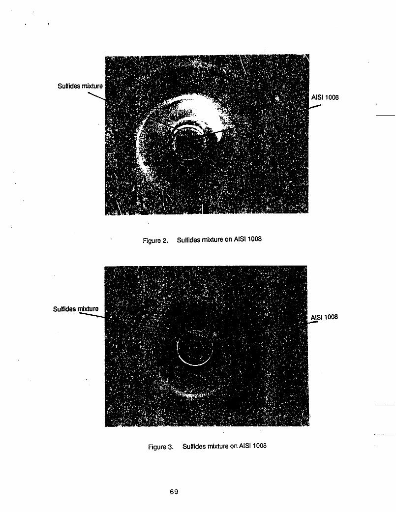
Sulfides mixture \
Figure 2. Sulfides mixture on AIS1 1008
1 i008
Sulfi des mixture \
Figure 3. Sulfides mixture on AIS1 1008
1008
69

Figure 4. Unpolished sample for 4150 at open air and IOOO'C with FeS : Na2S = 75 : 25
sanple(above), flake(below)
70

ngure 5. Unpolished sample for 4150 at open air and 1OOo'C with FeS : Na2S = 88 : 12
sanple(above), flake(bebw)
71

Figure 6. __ Unpolished sample for 1008 at open air and 1OOo'C with FeS : Na2S = 75 : 25
sanple(above), f!ake(bebw)
72

Figure.7. Unpolished sample for 1008 at open air and 1OOo'C with FeS : Na2S = 82 : 18
sanple(above), fhke(bebw)
73

,
Figure 8. Unpolished sample for 18-8 at open air and 1 OOO’C with FeS : Na2S = 75 : 25
74
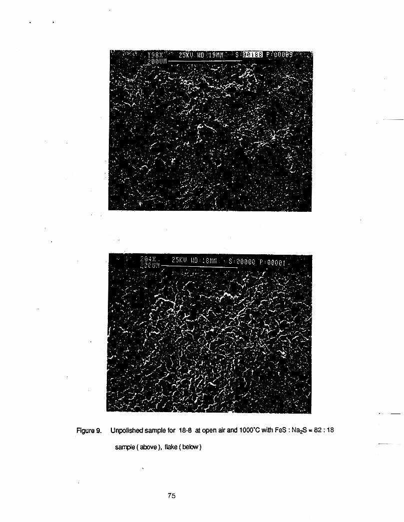
Figure 9. Unpolished sample for 18-8 at open air and IOOO'C with FeS : Na2S = 82 : 18
sar@e(abxe), flake(bebw)
75

Figure 10. AIS1 4150 @eel and scale and scale casing at open air and 1OOo'C
76

Figure 11. Polished and etched sample lor 4150 at A i atmosphere and IOOO'C
FeS : Nas-75 :25 ( above). 82 : 18 (below)
77

Figure 12. Polished and etched sample for 1008 at Ar atmosphere and IOOO'C
FeS : Na2S-75 :25 (above), 82: 18 (bebw)
78

Figure 13. Polished and etched sample for 18-8 at Ar atmosphere and 1OOO'C
FeS : Na2S =75 : 25 (above), 82 : 18 (bebw)
79

Figure 14 At open air and IOOO'C for 20 hrs the Cu sample showed a l x f & m W W m
80

-re 15 At AradmoJphere and I W C f o r 2 0 lusthe Cu sample remained
UnhargedHlilhmmddaliOn
81

Figure 16 Polished and etched sample for 4150 at open air and IOOO'C with
FeS : N&S -75 : 25 (above), 82 : 18 ( b b w )
82

Figure 17 Polished and etched sample for 1008 at open air and 1000' C with
FeS : N*S-75 :25 (above). 82 : 18 (bebw)
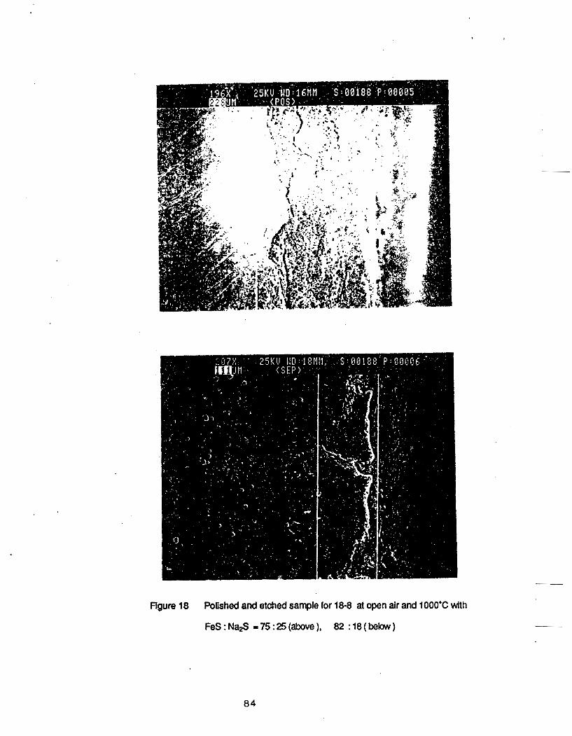
Rgure 18 Polished and etched sample for 18-8 at open air and 1OOo'C with
FeS:Nas -75:25(above), 82 :18(below)
8 4

Figure 19 Polished and etched sample for 4150 at Ar atmosphere and 1OOO'C with
FeS : N a S 175 : 25 (above), 82 : 18 ( balow)
85

Figure 20 Polished and etched sample for 1008 at Ar atmosphere and 1000' C with
.FeS : N& S = 75 : 25 (above), 82 : 18 (bebw)
86

Figure 21 Polished and etched sample for 18-8 at Ar atmosphere and1000'C with
FeS : Na,S- 75 :25 (above), 82 : 18 (below)
87


Report for Preliminary Experiment: Observation of Interfaces
between Solid Copper and Liquid Matte, and between Solid Iron and Liquid Matte
1. Jlmbo and A. W. Cramb
Deparbneni of Metallurgld Engineering and Materials Sdence
Camegie Melion University PHtsburgh, PA 15213
89

1. Introduction
As discussed in previous reports ' a z , the authors have found that solid scrap treatment is a
promising method to remove solid copper from ferrous scrap. The major merits for this process
can be summarized as follows:
1. Lower temperature; below the melting point of copper (l08SC)
2. Very high copper padon ratio; about 500
3. No sulfur pick-up 4. No need to carburize or decarburize the liquid metal
Based on these findtngs, a large scale experiment using a several-hundred-kiiogram-
capacity rotary kiln is planned. One of the important factors in this pilot plant scale experiment Is
to determine the mechanism of drainage of liquid sulfide from solid iron to facilitate the separation
of fenous scrap from liquid matte after refining. In this study, we have measured wetiability of
liquid sulfide to solid iron and solid copper. This report describes the result of a preliminary
experiment to determine the extent of wetting between llquld matte and solid iron and solid
copper. In addhion, the interfacial reaction was photographed using X-ray radiography.
II. Experlmental Procedure
Experiments were carried out to observe the wettabiilty of a liquid FeSMa$ sulfide on solid
iron and copper using X-ray radlographic technlque. The wmposfflon of the premelted sufflde
mixture was 75 wt% - iron sufflde (FeS) I25 WWO sodium sufflde (Na$). The estimated melting
temperature of which is about 810OC. A high pwily (99.6%) alurnlna crudble, which con!alned a
wlumnar piece of copper (7 mm In diameter, 19 mm long) or iron (15 mm in diameter, 30 mm
long) along with the sulfide particles, was charged into the preheated electric lumace. The
experimental temperature was 1000°C, and the atmosphere was agOn-5% c a h n monoxide.
The condition for X-ray photography was 50 kVp, 100 mA tube ament, and exposure time 0.5
second. A diagram of the experimental apparatus is given In Figure 1,
90
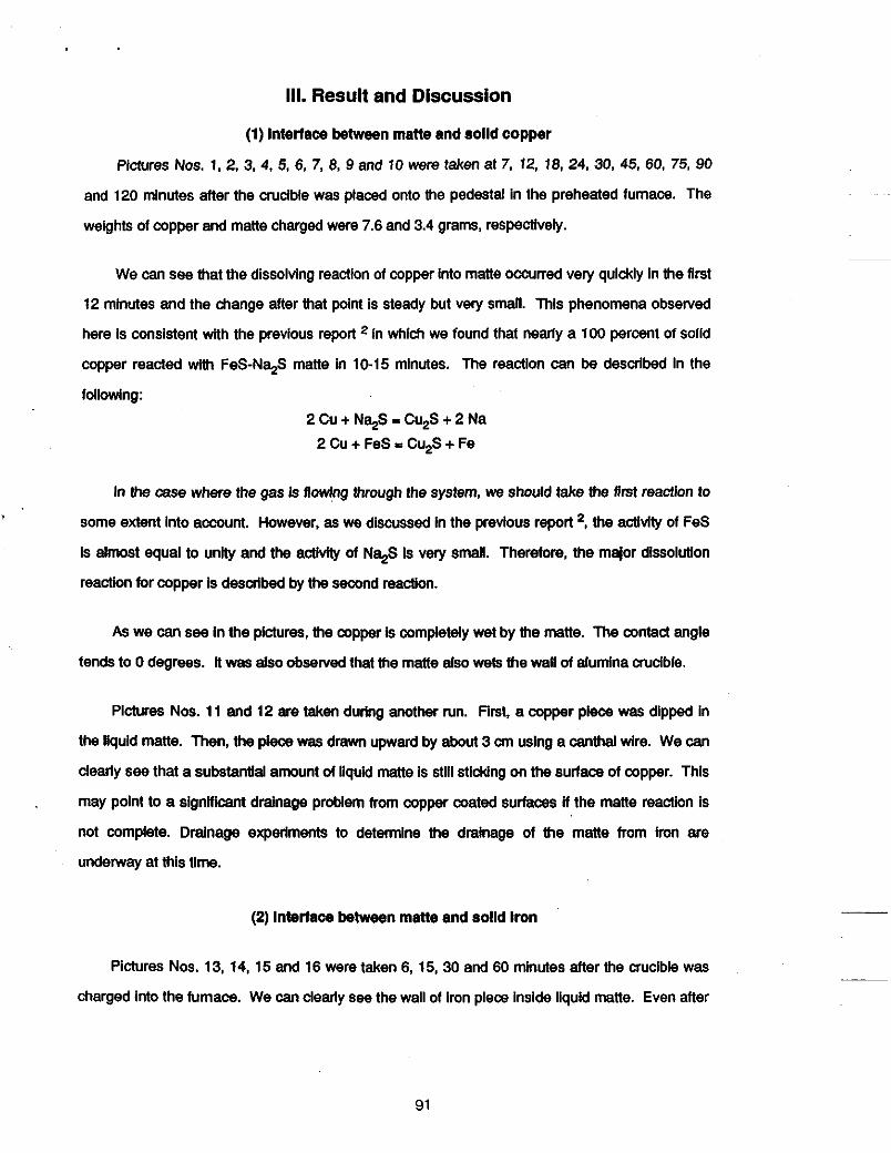
111. Result and Discussion
(1) Interface between matte and solld copper
Pictures Nos. 1. 2. 3. 4. 5, 6, 7, 8, 9 and 10 were taken at 7. 12. 18, 24, 30, 45, 60, 75, 90
and 120 minutes after the crucible was placed onto the pedestal in the preheated fumace. The
weights of copper and matte charged were 7.6 and 3.4 grams, respectively.
We can see that the dissolving reaction of copper into matte Occurred very quickly in the first
12 minutes and the change after that point is steady but very small. This phenomena obselved
here is consistent with the previous report in which we found that nearly a 100 percent of solld
copper reacted with FeS-Na$ matte in 10-15 minutes. The reaction can be described in the
following: 2 Cu + N+S - Cu,S + 2 Na
2Cu+FeS-Cu2S+Fe
in the case where the gas is flowing through the system, we should take the first reaction to
some extent into account. However, as we discussed in the previous report *, the aclivity of FeS
is almost equal to unHy and the activXy of N4S Is very small. Therefore, the major dissolutlon
reaction for copper is desuibed by the second reaction.
As we can see In the pictures, the copper is completely wet by the matte. The contact angle
tends to 0 degrees. It was also obselved that the matte also wets the wall of alumina crucible.
Pictures Nos. 11 and 12 are taken during another run. First, a copper piece was dipped in
the liquid matte. Then, the piece was drawn upward by about 3 an using a canthal wire. We can
dearly see that a substantial amount of liquid matte is still sticking on the surface of copper. This
may point to a signiiicant drainage problem from copper coated surfaces ii the matte reaction is
not complete. Drainage experiments to determine the drainage of the matte from iron are
undenvay at this time.
(2) Interface between matte and solld Iron
Pictures Nos. 13, 14, 15 and 16 were taken 6, 15,30 and 60 minutes after the mcibie was
charged into the fumace. We can clearly see the wail of iron pleca inside liquid matte. Even after
91

60 minutes, the iron has not reacted with the matte. The interface remains constant during the
experiment. The system is saturated with FeS, and the activity of Na$ is veIy small. Therefore,
the following reaction Fe + N+S = FeS + 2 Na
does not proceed. From the pictures. we can see that the matte wets the iron, although this
is not as large an effect as for copper.
IV. Closing Remarks
As expected, FeS-Na$ matte showed a slgnMcant wetting behavlor to solid copper and
solid iron. A substantial amount of matte stuck to copper when copper was drawn out of the
liquid matte. Future experiments will be conducted to enhance drainage of the matte from steel
samples.
V. References
1.1. Jlmbo, M. S. Suisky and R. J. Fruehan: l&S Maker, Vol. 15, No. 8, (1988),
2. I. Jimbo and R. J. Fruehan: Unpublished Report, Center of lnxl and Steelmakhg
pP.20-23.
Research. Carnegle Meilon University (1987).
92

X I I Alumina Tube :-Ray Source Crucible
Mullite Tube Sample \ '-d
\ I \
I 1 Collimeter
X-Ray 4
Film C
Aluminum Foil I ' Aluminum Foil Ceramic Fiber
High Temperature Ceramic Fiber Layer Ceramic Fiber
FiPure 1. ExDerimental Apparatus
\ Casset
Film
lassette
tte Hold .er

Plcture 2 12 min at 1 OOO°C
Plctum 4: 24 mln at 1000%
Plcture 6 45 min at 1OOO"C __
Plcturea 1 - 6 Solld copper Immersed In FeS-Na,S matte
9 4

Plctun 7: 60 min at 1000°C Pktun 8: 75 min at 1 Mx)"C
Plcture g: 90 min at 1000°C Plctun 10 120min at 1000eC
Plctures 7 - 1 0 Solld copper immersed In FeS-Nq matte
95

Plcture 12
Plchms 11 and 1 2 SoUd copper In contact with FeS-Nq matte at 1000°C
96

PIcture 13: 6 min at 1000bC Plchtre 14: 15 mln at 1000°C
Plcture 15: 30 min at 1000°C
plcturecl13 - 1 6 Solid iron immersed in FeS-Na$ matte
97


ClSR Progress Report
Preliminary Experiments for Removing Copper from Ferrous Scrap
L. Llao, Research Assoclate
A. W. Cramb, Assoclate Professor
R. J. Fruehan, Professor
Prior to setting up the kiln in the pilot plant at Universal, Pa, a number of prelminary experiments
were conducted in the experimental melt shop at CMU. The objectives of the experiments were to
determine the difficulty of drainage of matte from a sample after reaction; to determine if the matte would
easily penetrate motor windings and remove the copper; and, to determine if hydrous sodium sulphide
could be used in copper remval experiments. This effort is complimemtary to the efforts previously
reported by Mr. Zhang.
Matte Drainage
Small scale experimentation had indicated that the matte wet iron, copper and the alumina crucible
materials. This is a necessary first step for copper removal. Reaction of the matte with copper has also
been shown. The last step which must be tested, to ensure that the process is viable, is to prove that the
reacted matte can be easily seperated from the scrap.
To detem.ne the efficiency of drainage of matte from scrap two seperale experiments were
conducted. In the first a rotor and stator of a motor were dipped into a bath of molten matte at IOOOC.
The experimental set-up is shown In figure 1. After 15 minutes the pieces were removed and the matte
was seen to drain freely from the motor, leaving a very thin layer of matte on the motor. In this
experiment, as there was significant weight loss of the sample due to copper loss, it was difficult to
determine the exact amount of matte left upon the motor.
___
~
The second series of experiments were run with a simulated scrap charge. L angles of steel (40 x
99

40 x 3mm). steel plate (40 x 2 mm) and copper sheet were separately dipped into an 82% N+S, 18%
FeS bath at tenperatures of 800,900 and 1000 C. Emersion time was from 3 to 5 minutes in each case.
Copper Sheet
At all temperatures the copper sheet was completely dissolved within 3 minutes.
L Angle of Steel
Results of the drainage experiments for L angles of steel are shown in figure 2 where AM% is the weight
gain upon removal from the matte. At lOOOC the weight gain was minimal: however, signilcant amounts
of matte were found sticking to the samples as the temperature was lowered.
Steel Plate
Results of the Steel plate drainage trials are shown in figure 3. Again the amount of matte adhering to the
plate at 1000 C is very small: significant quantities of matte adhered to the plate at lower temperatures.
Motor Dip Tests
As noted earlier the motor dip tests were conducted at 1000 C. The rotor or stator was Inserted Into
the melt and slowly rotated at 22 rpm. Mer 20 minutes all of the copper windings in the bottom halt of the
motor windings were gone, as shown schematically in figure 4. Initially there was a quantity Ot smoke
released as the covering on the copper windings burned: however, after thls time. fume generation was
minimal. In a second set of experiments hydrous sodium sulphide was used. Copper removal results were
similar; however, fume generation was greater due to the reaction of H,O with the matte releasing some
so2
Discussion These preliminary results show that:
1. The matte (Na2S:FeS - 8298) is an effective reagent for copper removal from scrap.
2. 1000 Cis the best tempertaure of operation to ensure matte drainage from the sample.
3. Hydrous Na,S can be used to remove copper: however, fume generation Is higher than
4. Copper remval from motors is possible by simply dipping the motor into the matte.
when anhydrous sodium sulphide is used.
100
5. Reaction rates for copper removal are high.
Future Work
1. Determine the exact chemical species of offgases from decopperization experiments.
2. Complete larger scale dip testing.
3. Determine exact quantities of matte sticking to scrap at 1000 C.
101

Figure 1 Schematic of experimental arrangement for rotating rotor in sulfides melt at 1000 C
102

d
0 0
l o t g a
I I a 800 900 1000
Temperature of sulfides melt (OC) Figure 2 Drainage experiments for L steel angle
at different temperatures

3 3 c 3 a - a .c tn
104

Cu winnding
3opper winding ,-
Figure 4 Part of copper winding of rotor of a motor was dissolved by sulfides melt at 1000 C
-
105

106

PROGRESS REPORT
Removing Solid Copper from Solid Scrap - initial Kiln Experiments
L. Llao, Research Associate A. W. Cramb, Associate Professor
R. J. Fruehan, Professor
Aprll15,1990
INTRODUCTION
Based upon a series of indamental studies for removing copper from ferrous s q , large cale
experiments were conducted in a rotary kiln at Unhrersal, Pennsylvania. The objectives of these pre-pilot
experiments were to determine the efRdency of the procsss. to determine if the matte could be drained
from the Win and to determine if the scrap could easily be separated from the matte.
DESCRIPTION OF THE ROTARY KILN
The Win and Its supporting frame, hydraulic pump mechanism and exhaust system etc. Is
approximately 15 R long, 6 R wide and 9 R high. The gas bumer Is sltuated on one end with small holes
for matte drainage on the other, as Is shown In Figure 1 and 2. The worklng area of the Win consists of a
stainless steel cylinder which Is 2 R in diameter and 12 R long. The rotation speed of the Win can be
varied from 1 to 10 rpm. A hydraulic pump was used to tilt the Win. to hold the liquld matte In the kiln
during the experiment and to allow dralnage of the liquid matte from the Win. A stainless steel ring was
welded inside the Win as a matte dam In the high temperature area. Natural gas was used to heat the
shell of the Win and to lndirectiy heat the matte to the temperature needed for Mals. Nltrogen gas was fed
Into the Win to provlde protective atmosphere.
EXPERIMENTAL
The experimental pian and schedule of sampling are reviewed in Figure 3 and Table 1. For each
107

experiment 40-50 kg of matte was placed inslde the kiln. The FeS:Na$ ratio of the mane was 8218 at
1000°C or 7525 at 900%. 70-80 kg of assorled ferrous scrap (steel rods, plpes. angles, plates etc.) was
charged Into the klkt. The amount of matte used 1s more than that needed to remove the copper. but Is
the minimum necessary to have a liquid matte pool In the Wln.
After the natud gas was ignited the kiln rotation was initiated at 2 rpm. 20 mlnutes later, the mane
was parUy melted and liquid mane pool had formed. The klln rotatlon speed was then increased to 5 tpm.
35-40 minutes later, when the matte temperature reached 900°C, the rotation speed was increased to 10
rpm. At lhal time the matte had melted completely and a large llquld pool had formed. The matt8 was
very fluid and wet the scrap. After the flrst sample was taken, 3.4 kg of copper (tubing wound on steel
rods) was added to the kiln to Increase the copper content In the scrap to 4%. 2 minutes after addlng the
copper, a large pert of the copper, by visual Inspedlon, had dissolved Into the matte. 5 mlnutes later, a
second sample was taken. The copper tubing was found to have completely dlssolved Into the matte
withln 6 to 7 ndnutes after addition at 900°C and withh 4 to 5 mlnutes at 1ooo"C. Additional samples were taken every 10 mlnutes, as Is shown In Figure 3.
After the treatment, the liquid matte was completely draJned Into a conteinef by gradually tilting the
klln. Only a thin layer of matte stuck to the Inside surface of the kiln and the surface of the ferrous scrap.
The drainage of llquld matte was more complete at 1000°C than at 900%.
After each experiment, the matte and the scrap were carefully examined. No pieces of copper
were left in &her the matte or the map. The copper dissolved completely Into the matte. it was also
found that the scrap pieces became thhner during the trial, while the amount of matte Increased due to
the oddatlon of kon by air.
RESULTS AND DISCUSSION
Regardless of matte chemistry or kiln temperature, the llquld matte pool was formed within 20
mlnutes of heating In the Wln. The copper (around 4% In scrap) was completely dissolved within 6-7
minutes after addition at 900% and within mlnutes a! 1000°C. Thls shows that the matte process Is __
~~
effldent for removing copper from ferrous scrap and that the solid treatment process could be a
successful process technology. -
108

The chemical analyses for a typical experlment Is shown in Table 2, Figures 4 to 9. Figure 4 show
that 2 minutes after copper was added, copper content in matte increased to 1.47% and to 8.42% within 5
minutes. In other words, copper was removed by the matte within a very short time. Meanwhile the
amount of matte increased almost linearly f” 45.4 kg to 61.627 kg (from first sample to sixih), because
Iron In the swap was oxidized gradually and continuously dissolved into the matte in the form of iron
oxides. 1.578 kg of iron of scrap had dissolved Into the matte when third sample was taken; and 7.15 kg
of iron of scrap had gone into the matte when sixth sample was taken. Thus the copper in the matte
decreased after third sample and the content of Na and Fe in the matte also decreased from the
beginning until the end. Figure 5 shows the same results In terms of Cu$, Na& FeS. In future
experiments, once the copper is removed, it will be appropriate to minimize scrap residence time to
minimize iron loss, and to better seal the apparatus to stop oxidation.
FUTURE WORK 1. Determine the effect of increasing matte C u s content
2. Test the process as a means of recyding of eiecblc motors.
3. Measure accurately the amount of matte sticking on the metal. 4. Carry out continuous experiments in the kiln where s a a p containing copper Is continuously
added into the kiln and the refined product Is continuously removed.
109

because iron in the scrap was oxidized gradually and continuously dissolved into the matte in the form of
iron oxides. 1.578 kg of iron of scrap had dissolved into the matte when third sample was taken; and 7.15
kg of iron of scrap had gone into the matte when sixth sample was taken. Thus the copper in the matte
decreased after third sample and the Content Of Na and Fe in the matte also decreased from the
beginning until the end. Figure 5 shows the same results in term of Cu,S, Na2S, FeS. In future
experiments, once the copper is removed, it will be appropriate to minimize scrap residence time to
minimize iron loss, and to better seal the apparatus to stop oxidation.
FUTURE WORK 1. Determine the effect of increasing matte Cu2S cOntent
2. Test the process as a means of recycling of electric motors. 3. Measure accurately the amount of matte sticking on the metal.
4. Carry out continuous experiments in the kiln where scrap containing copper is continuously added into the Wln and the refined product is continuously removed.
110

Table 1 The experiments performed in the kiln
111

Table 2 Chemical analysis results of the matte of a typical experiment in the kiln
112

Figure 1 The rotary kiln for large scale experiments at Universal
11 3

ekhausf gas cylinder small holes exhaust
gas steel ring of the kiln for dralnage stainless
1 \
dralnage of matte
stalnless steel rlng
Figure 2 The rotary kiln and (A) the position for refining and (B) the position for drainage of the matte
114
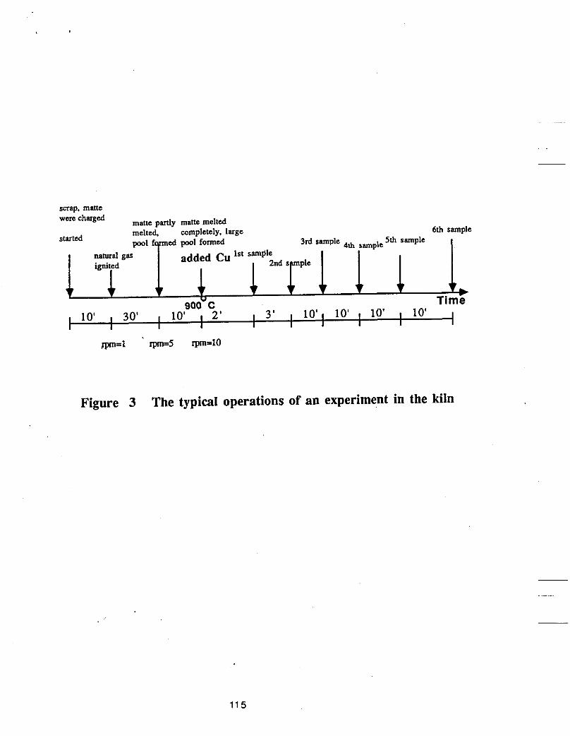
pool f m e d pml formed 3rd sample 4th sample 1st sample natural gas added Cu
Figure 3 The typical operations of an experiment in the kiln
115

0
0
Time (min)
Figure 4 The Change of copper in the matte as a function of time
116

1
11
4 8 Q Z
E
7
0
0 0
0
0
0 10 20 30 40
Time (min)
0
Figure 5 The Change of Na in the matte as a function of time
117

5 :
5
4
8 4 a L
4
4
4
0
0
I I 1 1 20 30 40 I 10
Time (min)
0
Figure 6 The Change of Fe in the matte as a function of time
118
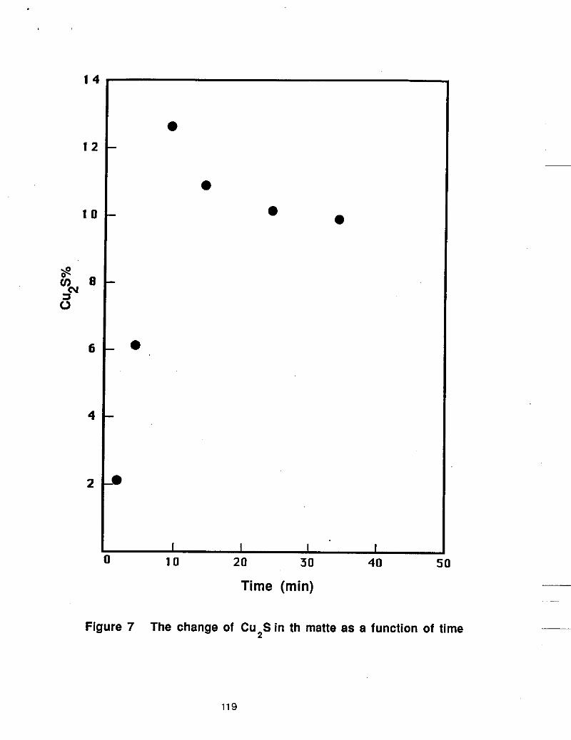
1 4
1 2
1 0
8 8
5
6
4
2
0
0
0 0
0
B
I I I 1
10 20 30 40 50
Time (min)
Figure 7 The change of Cu2S in th matte as a function of time
119

18
17
16
s ON v)
z 15
14
13
12
, o 0
0
I I I I 10 20 30 40 3
Time (min)
Figure 8 The change of Na 2 S in the matte as a function of time __
120

0
84
80
76
72
68
64
6o 0
0
-0
-
-
0
-
-
I I I I 10 20 30 40
0
0
I
Time (min) Figure 9 The change of FeS in the matte as a function of time
121

122

ClSR PROGRESS REPORT
Removing Copper from Ferrous Scrap in a Kiln
L. Liao, Research Associate
A. W. Cramb, Associate Professor
R. J. Fruehan, Professor
September 15, 1990
introduction
Based upon a series of fundamental studies for removing copper from ferrous scrap, large
scale experiments were conducted In a rotating kiln at Universal, Pennsylvania. The objectives of
these prepllot experime,nts were to determine the efficiency of the process, to determine If the
matte could be drained from the kiln and to determine if the scrap could easily be separated from
the matte.
Description of the Rotary Klln
The kiln and its suppotting frame, hydraulic pump mechanism, and exhaust system etc. is approximately 15 ft long. 6 ft wide and 9 ft high. The gas burner is situated on one end with small
holes for matte drainage on the other, as is shown in Figures 1 and 2. The working area of the kiln
consists of a stainless steel cylinder which is 2 ft in diameter and 12 ft long. The rotation speed of the kiln can be varied from 1 to 10 rpm. A hydraulic pump was used to tilt the kiln to hold the Kquld
matte in the kiln during the experiment and to allow drainage of the matte from the kiln. A stainless
steel dng was welded inside the kiln as a matte dam in the high temperature area. Natural gas was
used to heat the shell of the kiln and to indirectly heat the matte to the temperature needed for
trials. Nitrogen gas was fed into the kiln to provide a protective atmosphere.
Experimental
The experimental plan and schedule of sampling are reviewed in Figure 3 and Table 1. For each experiment 40-50 kg of matte was placed inside the kiln. The FeS:Na2S ratio of the matte
123

was 82:18 at 1OOo'C or 75:25 at 9OO'C. 70-80 kg of assorted ferrous scrap (steel rods, pipes,
angles, plates etc.) was charged into the kiln. The amount of matte used is more than that needed
to remove the copper, but is the minimum necessary to have a liquid matte pool in the kiln. The
natural gas was then ignited and the kiln rotated at 2 rpm. 20 minutes later, the matte was partly melted a liquid matte pool had formed. The kiln rotation was then increased lo 5 rpm. 3540
minutes later, when the matte temperature reached 9OO'C, the rotation speed was increased lo 10 rpm. At that time the matte had melted completely and a large liquid matte pool was formed.
The matte was very fluid and wet the scrap. After the first sample was taken, 3.4 kg of copper
(tubing wound on steel rods) was added to the kiln to increase the copper content in the scrap to
4%. 2 minutes after adding the copper, a large part of the copper, by visual Inspection, had
dissolved into the matte. 5 minutes later, a second sample was taken. The copper tubing was
found to have completely dissolved into the matte within 6 to 7 minutes after addition at 900%
and withln 4 to 5 minutes at 1OOO'C. Additional samples were taken every 10 minutes, as Is shown in Figure 3.
After the treatment process was finished, the liquid matte was completely drained through
the small holes into a container by gradually tilting the kiln. Only a thin layer of matte stuck to the
inside surface of the kiln and the surface of the ferrous scrap. The diainage of liquid matte was
more complete at 1OOO'C than at 9OO'C.
After each experiment. the matte and the scrap were carefully examined. No pieces of
oopper were left in either the matte or the scrap. The copper was dissolved completely Into the
matte. It was also found that the scrap pieces became thinner during the trial, while the amount of
matte increased due to the oxidation of iron by air.
Results and Discussion
Regardless of matte chemistry or kiln temperature, the liquid matte pool was formed within 20
minutes of heating in the kiln. The copper (around 4% in scrap) was completely dissolved within
6-7 minutes after addition at 9Oo'C and within 4-5 minutes at 1OOo'C. This shows that the matte
process is efficient for removing copper from ferrous scrap and that the solid treatment process
could be a successful process technology.
The chemical analysis for a typical experiment are shown in Table 2, Figures 4 to 9. Figure 4
shows that 2 minutes after copper was added, copper content in matte increased to 1.47% and to
8.42% within 5 minutes. In other words, copper was removed by the matte within a very short
time. Meanwhile the amount of malte increased almost linearly from 45.4 kg to 61.627 kg (from
first sample to sixth), because iron in the scrap was oxidized gradually and continuously dissolved
into the matte In the form of iron oxides. 1.578 kg of iron of scrap had dissolved Into the matte
124

when third sample was taken; and, 7.15 kg of iron of scrap had gone into the matte when sixth sample
was taken. Thus, the copper In the matte decreased after third sample and the content of Na and Fe In
the matte also decreased from the beginning until the end. Figure 5 show the same results In terms of
Cu,S, N+S and FeS. In future experiments, once the copper Is removed, it will be appropriate to
minimize scrap residence time to minimize iron loss, and to better seal the apparatus to stop oxidation.
No matter what ratio (FeS:Na&82:18 or 75:25) was used in experiments, even when the matte
with 9.35% Cu2S content was used, the copper in scrap was dissolved within 4-5 minutes at 1000°C, and
it was dissolved within 6-7 minutes at 900°C. The matte could be drained easily out of the kiln at lO0OoC,
while at 900% the matte could hardly be drained out of the kiln but stuck to the wall of the kiln.
In order to examine the change of the sulfur and copper content of the swap before and after
experiment, the scrap with sticking matte was remelted In the Induction furnace and cast Into a ingot
mold. Three samples were taken and analyzed for sulfur and copper contents. The analysis shows that
the copper content remained almost the same (0.5%), the sulfur content after experiment (0.159%) was
three times higher than the original sulfur content (0.043%). However, after the saap was washing using
water, remelted and analyzed, the sulfur content of the scrap deaeased from 0.159% to 0.095%.
Furlhennore, the scrap was placed Into the 8% HCI solution for washing and cleaning the sticking matte
at 102% for 30 minutes, then It was rinsed in the water and analyzed, the sulfur content of the scrap
decreased again from 0.095% to 0.053%. That means the problem with increased sulfur wntent after
experiment can be solved by the above measures.
Summary
1. The process is effective to remove copper from scrap and from electric motom at 1000°C.
2. The matte can be reused.
3. The problem of lnaeasing sulfur content of the saap after experiment can be solved by
using water and 8% diluted HCI soluthn to wash and dean the sticidng matte.
125
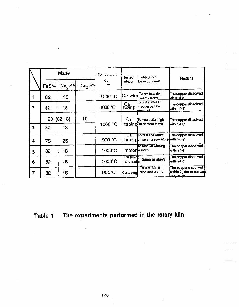
I I I
Matte Temperature Results tested objectives
OC object for experiment
To see how the
FeS% N%S% C y S % The copper dissolved
The copper dissolved
1000 ‘C within 4-5’
82 18 within 4-5’
82 18 cu wjrc”occsr wo*
90 (82:18) 10 CU To test initial high The copper disoolved 1000 ‘C tubinccucontent matte within 4-5’ 82 18
75 25 900 ‘C tubingof bwer temperature within 6-7’
82 18 1 OOO’C motor n motor within 4-5’
C;U To test the effeled The copper dissolved
The copper dissohred 10 test Cu Wlndlng
I I I I I I
I he copper dissolved 1 Ooo’c I cutubiT$ and mot r Sameasabove Llh,n44, 82 18
Table 1 The experiments performed in the rotary kiln
126

Table 2 Chemical analysis results of the matte of a typical experiment in the kiln
127

Figure 1 The rotary kiln for large scale experiments at Universal
128
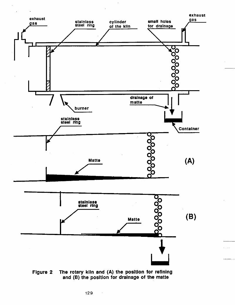
exhaust exhaust
small holes
stainless steel ring Y Container
/ L
I Matte
/- (A)
I stainless steel ring
I
c U
Figure 2 The rotary kiln and (A) the position for refining and (9) the position for drainage of the matte
129
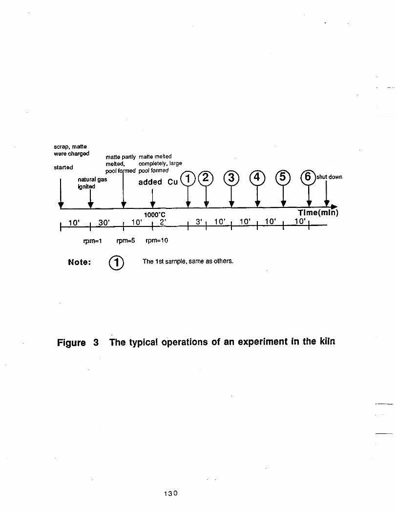
scrap, mane were charged mane Dafllv mane melted .~
melted. completely, large pool famed pool formed
started
added Cu natural gas
t c 10' I 1 10' I
1 I
rpm=l rpm4 rpm=lO
Note: @ The 1st sample, same asothers.
Figure 3 The typical operations of an experiment in the kiln
130

11
8
6 8 S 0
4
2
I 0 10 20 30 40
Time (min)
Figure 4 The change of copper in the matte as a function of time
131
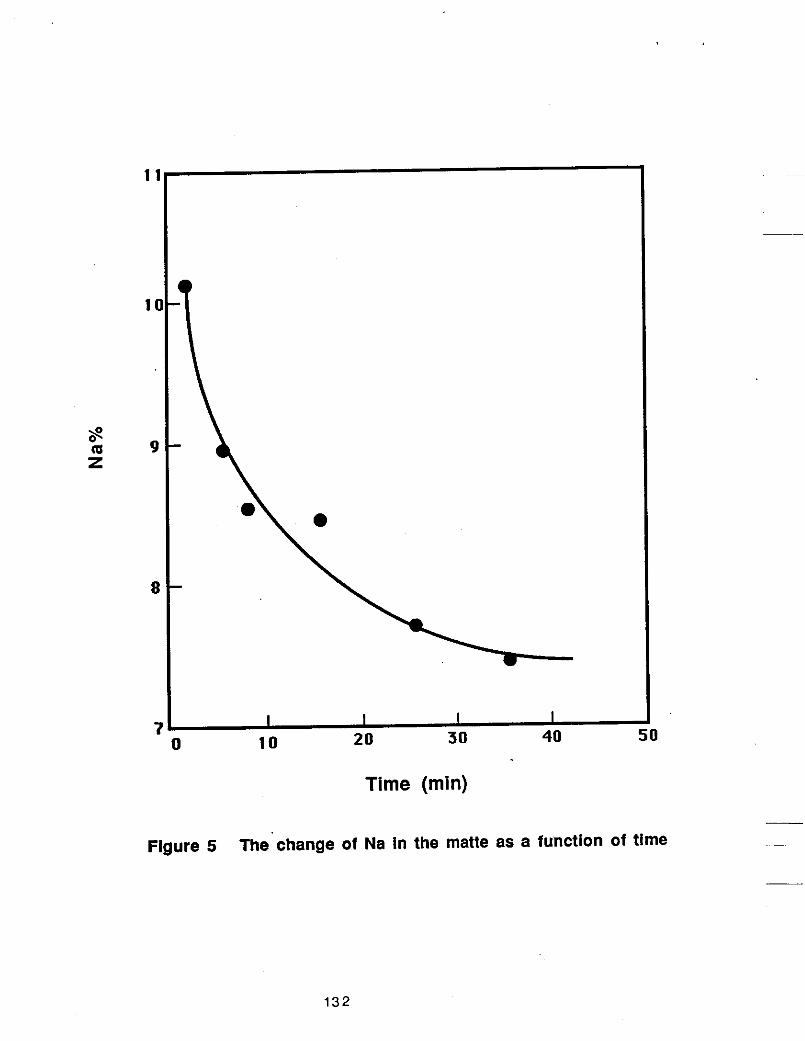
I I I I 1
0 10
Time (min)
Figure 5 The change of Na in the matte as a function of time
132

44
42
40 I
Figure 6 The change of Fe in the matte as a function of time
-
-
t I I I
Time (min)
133

1 4
1 2
1 0
S 8 viy 3
6
4
2
I I I I I 30 40 50 I 10 20
Time (min)
Figure 7 The change of Cu,S in the matte as a function of time
134

18
17
16
14
13
12
r
I I I I 10 20 30 40 0
Time (min)
Figure 8 The change of Na2S in the matte as a function of time ___
135

Experiment 1
1. Objective: To see how the process works. 2. Matte: 31.3 kg
FeS 20 kg Na2(60%) 7.5 kg (82:18)
copper (tubing) 1.02 kg 3. Ferrous scrap: 66 kg (steel rods, iron angles, steel pipes and steel sheets)
4. Temperature: 1000 'C
5. Experimental:
copper dissolved completely
0' 2 5 6' 15 . 26 1000 'C
6. Chemical analysis results:
136

Experiment 2
1. Objective: To see if more Cu tubing in scrap (Cu=4.08%) can be removed. 2. Matte: 50.5 kg
FeS 37 kg Na2S(60%) 13.5 kg (8238)
copper (tubing) 3.4 kg (Cu=4.08%) 3. Ferrousscrap: 79 kg
4. Temperature: 1000 'C
5. Experimental:
copper dissolved w mpletel y
matte was drained
0' 1' 5 1 5' 25 1000 'C
6. Chemical analysis results:
137

Experiment 3 1. Objective: To do experiment using high Cu,S content matte. 2. Matte: 41.66 kg
FeS 31.7 kg Na,S(60%) 11.6 kg (82:18) c u *s 4 kg (CU S=9.38%)
3. Ferrous scrap: 80 kg
4. Temperature: 1000 'C
5. Experimental:
copper (tubing) 3.4 kg (Cu=4.08%)
copper dissolved completely
matte was drained completely
0 ' 2 ' 5' 1 5' 25' 35' 1000 'C
6. Chemical analysis results:
cu 8.12 . 13.55 14.7 13.01 12.41 12.35
Fe 54.8 52.3 49.1 50.22 44.6 51.8
Na 8.47 5.98 5.89 6.22 5.89 4.97 i
5' 1 5' 25' 35' 45' I I I I
138

Experiment 4
1. Objective: To test the matte with FeSINa, S=75:25.
2. Matte: 42 kg FeS 31.5 kg Na2(60Y0) 17.5 kg (7525)
copper (tubing) 3.4 kg (cu=4.04%) 3. Ferrousscrap: 81 kg,
4. Temperature: 1000 'C
5. Experimental:
matte was drained
0 ' 1 3 7'8 18 28' 1000 'C
6. Chemical analysis results:
cu 1.47
2' 5' 15' 25' 35'
4.02 8.42 7.2 6.99 6.6
Fe
N a
~~~
Note: Before the matte was drained, it was very thick. The Cu tubing dissolved into the matte within 7.
I
51.39 44.3 44.77 47.09 48.83 44.1
10.11 8.92 8.69 8.6 7.77 7.56
139

Experiment 5 1. Objective: To test if the winding in the motor dissolves into-the matte.
2, Matte: 23.4 kg FeS 19.2 kg N%S(60%) 7 kg (82:18)
3. A motor was added (no ferrous scrap)
4. Temperature: 1000 'c 5. Experimental:
copper winding drained the in motor disslved gat matar malt8 out of added
motor out of the koln the Win
I 0' 1' 2' 4' 6 14' 16 18' Time(min)
1000 'C
b
1' 4'
cu 0.32 0.35
Fe 51.94 51.2
Na 10.55 9.84
14'
2.31
50.03
9.81
1' 4'
cu,s 0.41 0.44
FeS 81.37 80.67
Na, S 17.89 16.69
140
14'
2.89
78.69
16.63

Experiment 6
cu
Fe
N a
1. Objective: A demonstration. To test using both the motor and the Cu tubing.
2. Matte: 36.6 kg FeS 30 kg N%S(60%) 11 kg (82~18)
3. Ferrous scrap: 60 kg a motor copper (tubing) 3.8 kg
4. Temperature: 1 OOO'C
5. Experimental::
0.1 24 0.184 4.02 6.1 1
53.1 52.95 50.46 48.59
9.7 8.27 8.16 6.94
added drained the matte out of the kiln
b
3'
cu,s 0.1 4 0.23
F e S 83.61 83.25
Na, S 16.54 14.03
6.
6' 16'
5.03 7.64
79.33 76.39
13.84 11.76
0' 1' 3 5 6 1 OOO'C
Chemical analysis results:
1 6 18
I I I 3' 6' 16'
1 4 1

Experiment 7 1. Objective: To test how the process works under the conditions of:
(1) 9oO'C, (2) FeS:Na$=82:18. 2. Matte: 25 kg
FeS 20.5 kg N%S(60%) 7.5 kg (82~18)
3. Cubing 1.7 kg, stainless steel rod.
4. Temperature: 900 'C
5. Experimental: copper disso'ved copper dissolved, all the matte slowly' the matte stuck to the wall of the furnace.
The matte could not be drained ovt of the
b
cu
Fe
Ne
0' 1' 7 12 9OO'C
0.32 2.85 3.42
52.65 50.75 49.7
10.36 9.91 9.46
6. Chemical analysis results:
0' 7'
cu,s 0.32 3.57
FeS 82.81 79.83
Na, S 17.57 16.81
15' Time(min)
IT
4.28
78.25
16.04
0' 7' 12' ! ! I ! I
Note: The amount of the matte sticking to the rod/ the weigM of stainless steel rod=l.94%
1 4 2
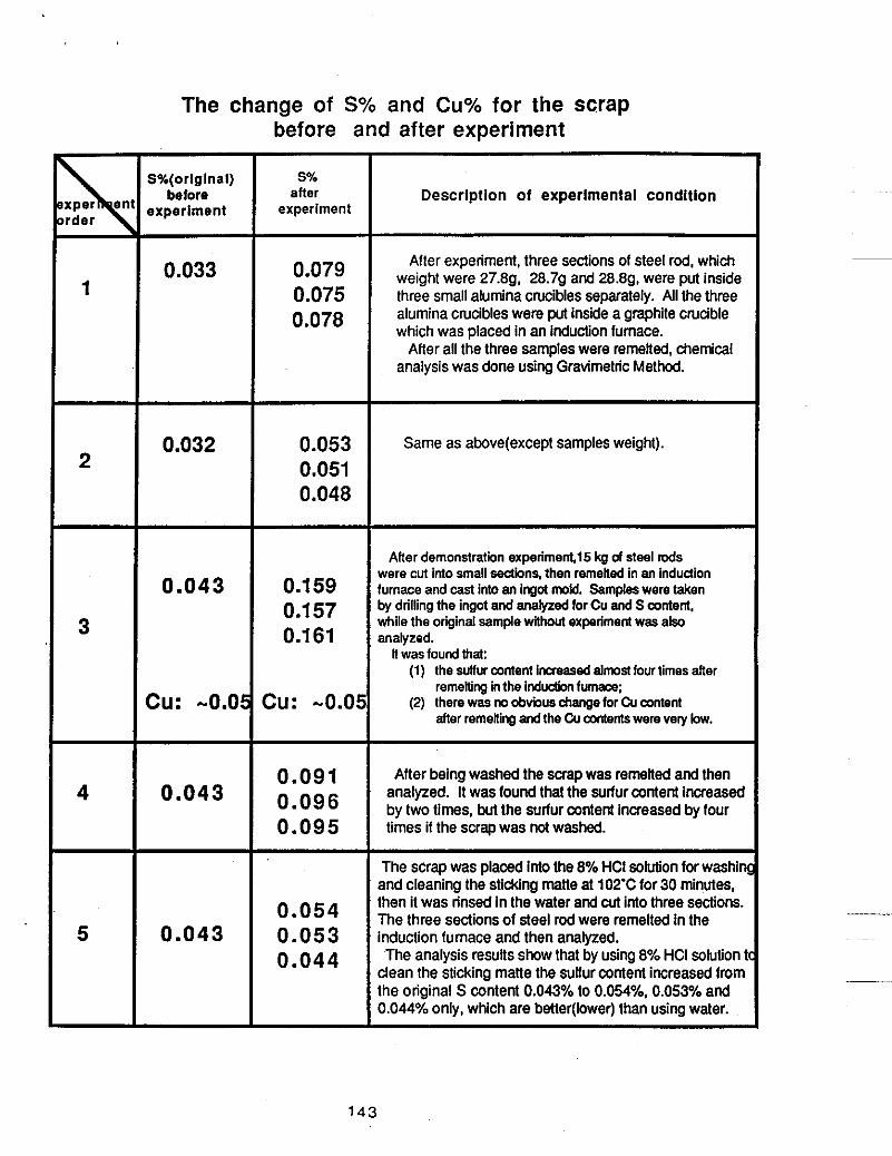
The change of S% and Cu% for the scrap before and after experiment
S%(orlglnal) before
experlment
0.033
0.032
0.043
cu: -O.O!
0.043
0.043
S% after
experiment
0.079 0.075 0.078
0.053 0.051 0.048
0.1 59 0.1 57 0.1 61
cu: -0.0
0.091 0.096 0.095
0.054 0.053 0.044
Descriptlon of experlmental condition
After experiment, three sections of steel rod, which weight were 27.8g, 28.7g and 28.89, were put inside three small alumina crucibles separately. All the three alumina crucibles were put inside a graphite crucible which was placed in an induction furnace.
After all the three samples were remelted, chemical analysis was done using Gravimetric Method.
Same as above(except samples weight).
After demonstration experiment15 kg of steel rods were cut into small &ions. then remetled in an induction furnace and cast Into an ingot mold. Samples were taken by drilling the ingot and anaiyzed for Cu and S content. while the original sample wlthoul experiment was also analyzed.
ll was found that: (1) the sulfur content ineased almost four times after
remetling in the induction fumaca; (2) there wes no obvious change for Cu content
after remeking and the Cu contents were very bw.
After being washed the scrap was remelted and then analyzed. It was found that the sulfur content increased by two times, but the sulfur content increased by four times if the scrap was nd washed.
The scrap was placed into the 8% HCI solution for washin and cleaning the stiddng matte at 102'C for 30 minutes. then it was rinsed In the water and cut into three sections. The three sections of steel rod were remelted in the induction furnace and then analyzed. The analysis results show that by using 8% HCI solution 1
clean the sticking matte the sulfur content increased from the original S content 0.043% to 0.054%, 0.053% and 0.044% only, which are betler(lower) than using water.
143

144

- - .I. , ,
Work Report
DECOPPERlZATlON OF FERROUS SCRAP
Ru@funW 8mIUng Is of mlnor interests nowedeys. However, a patent pubWm In
Crechoslovalda In 1b1O1 adopted this method fw copper recovery from iron saap. According to the
ab~rrad de9aiption, cu is melted wiective~~ in an tu& and separated from /=e In a iayer of
CeO-FeOSi02basetslag by vibration and gravltatlon andcoUeUed at bath bottom separallon fnthe
molten slag prevents oxldlzatlon and contact of Fe with CU. The mered products contalned CX 98-99
and Fe 0.4-0.8%.
__
(k) Vucuum d/sf/1/8t/on Is still interesting to a number of researchers [I1] and some Improvements
have been proposed. T. Matsuol'a investigated the copper and tin removal in a laboratory scale plasma
-
145

furnace uslng argOn-hydFogen and argon gas. Cu and Sn removal was much accelerated. Degrees Of
Cu and Sn "oval mached 90 and 60% respectively In 2 houn. It was concluded that a hlgh /-$content
In plasma gas and a hlgh lnltlal oarbon content were favorable. Effective removal of these elements m M
be obtained at pressures of 13X10'-2~tlO'Pa (0.12etm-020aen). C.N. Eslmal~f3~ also suggesled that
additlon of slllcon to the molten metal enhances the rapodretion of copper and tln. And tln evaporates
even faster than copper does. When add lOwt% Si, copper was removed from Iwt% to a final O.DGwp/.
and tin from lw% to O.O45wt%. Unfomnately, the Mgh SI content In the product may Rmlt the range of
usageofthereclalmedsCrq).
(v) S/ug reffnrng of copper hwn liquld scrap has been attracHng the most attention of the
reseamhers, slnce tMs technfque Is relertvely cheap and may be used In eltherfumace or ladle. Major
p"6 arethatlt q u h ~ ~ r e f l o n of liquld metal anda datively hlgh tempem Wch may cause vapodratlon of A+@. Also resuphurltaton was found after the treatment wMch Is unfavorable for
the aftemard steel Mnlng. Men?@ to find the slagglng agents other than N+ (or Ne04 or
methods to reduce Its veporlzatlon have been made, but there am no achievements yet without sacrlfldng
the decopperlzstlon eftldency. Major wocks revlewd are llsted In Table 1.
(vl) A low f e m w 0xMlrSllon method was revealed by CJ. Herter.@l In this procwss, a kiln
is malntalned at an oxidldng atmosphere at about 17OOF(927%). As ChaQW mwe thhmugh the Idln, the
atomsphere changes from oxldldng to new and redudng, klln tenperature r(ses to 19ooF(Iw8'C) at I
the dlsdullge end. Cu may be removed as Cvodust fromthe oxldlzlng pad of the rotacy kiln as a
nWalUc brlWe soale. Test results ohowed that the method could be VI&. However no detailed
publicatton related to thls wnd of technique could be found.
As the above lndlcatea m, system has been appcoved to be the only rellable fluxing agent
for copper removal from the liquid fenws scrap. Acmrdlngly, Fruehan dlsl also chose Fes-Nes,, for
their low temperature solid state treatment method. The pdndple of thk method then relles on that the
affinity of S for Cu Is greater than that for Fe. Thus, - q,) + $F"a, = (~sOdm#tc+; %) (1 )
__ While selves as a solute to reduce the msltfng temperatures of the matte.
146

T . l d etalrpl obtalned the l soact l~ ooeffident contours of &so, amd FeS for
~ g F e S C u S , , s ternary system at 1200% and showed that the advlty coeffldents of both
components decrease wlth imaslng (%NaSo.d. They expialned that Na# fonning many compounds
wlth Cu# and FeS mlght be the mason for the &crease In vas, and 7- wlth IncreSSing (%Ne,).
seeFig.1 and2
1. Jlmbo et@l also pbtted their experimentally obtained Raoultlan actMties at 1 W C of Gusod and FeS In the EJeso6FeSC&05 Mangle. But thelr data were too scattered fo form the Isopleth
(Fl6F3.4). However, they reasonably concluded that (Flg.6.6 and 7):
coeffldent of CuSod
~ccording to the CSR work phn on this project, the major task wln be setting up a pilot scaie mtaw Wln and testlng the concept on thls unit pmcess. And "e prellmlmy testa concemlng the Win
operatloneffldency arecunenny carlied OUtWl
(I) Foilowlng is a calculation on the mlnlmum amounts of matte and FeS required for sold state
decopperiradlon which show a minor dlfferm from that by 1. Jimbo!*l Assumlng wmaae kilograms
Initial matte Is requlred for extracting AW,, kilograms copper from solid scrap. After treatment completed.
the amount of matte becomes
__
1 4 7

or.
Therefore, the minimm matte requirement Is
whlch Is a little higher than Jlmbo's result 4l@lOOOkg.
In the above case,
148

w0,,,,,,e=23.7% w0-t 1383 kg 1-0M7Sx 34% AW,
Conseqixmtiy, the amount of FeS needed In the lnltial matte flux wFos would be
(n) The following are problems of mJof concern:
of copper dlssolurion Into the liquld matte ensudng a good mlxfng of capper includons in saap wlth the Squid matte and a higher rate
eUdnaUng adhesion of m e onto the femxrs element
4. Work Interests
0 T h e r " ( c pmpertles and Mdity of ternary Na%gFeSCuS,,, aquld matte at
temperatures of 700-1oooOC.
in Squid matte.
5. Relerrmceo
1. RJ. Fruehan; A.W. Cramb, Removal of Copper from Sccap, pmposcd to US DBpamnent
2 1. ambo; M.S. Sukky and RJ. Freuhan. /fun andsteeknsker. Aug..l988, Pp20-23
3. J. Peace and D. Engcedow, imnma/d~ahfSteehnatd~, 14(5),1987, pp240-252 4. P. VeJnar and V. Hrabak, Freiberg Forschungsh, A746, A I M , pp82-85 5. Y. Ogawa, J q m Patent, 16(1950), Jan. 11,1950
6. F.C. ~angenbeg and R.W. undsa/, r m . AIM, w i g w ) , pp9v-s~
7. W. Oelsen; E. Schuermann and Q, Helntichs, AtCh. B S e n h ~ 8 m , 90(1959), pp641-648
8. H. Schenck and W. Spleker, ,4&. Eisenhuettenw, 30(1959), pp641-648
9. H. Schenck and W. Spieker, &r. Pat. 1,146,891, Apr. 11,1963
of€mrgy, March 1.1988
10. E. Marecek; T. Langsadl and V. Rapmk, Czech. Pat CS240.566, Aug. 15,1987
11. D.N. Pocklington, Ironmaking and Stee/mMng, 12(1985). No.6. pp289
12. T. Malwuo. Trans. /SU, 28(1988). pp319-324
149

. . ..
13. C.N. Eslmal, Scand. J. Metali.. 16(1987). pp267-270
14. H. Schenck and (3. PerMx, Arch. WsenMenw, 33(1962),pp417-420
15. H. Schendq H. Roth and E. Stelnmetz, A&. Hsenhuttenw, 41(1970), prW95-603
16. H.V. Makar; E.W. Dunnlng Jr. and H.S. Caldwgfl Jr.. US Bur. M l m Res. Rep., RL7199,
17. H.V. Makar and B.W. Dunnlng Jr., J. Met&, 21(7),1969, pp12)-2;!
18. AA. Safiah and F.R. Sale, J. lmn and See/ Inst, 1972 pp52-56
19. X Uu and J.H.E. Jeffes, ImnWngandSwlWng, 12(1985), P@@-m 20. Y A Topkaya PhD Thesis. McMaster UnlverSlty, 1974
21. T. okazakl and D.G.C. Robertson, IrOnmeMng arni Sfe~31mahfng,12(1985), pp2905-B8
22. D.Q.C. Robertson, Pdvate comnunluaion
wm. 14pP
23. T. lmal and N. Sano, T m . /SU, 28(1988), 699-1005
24.1. Jlmbo, M.S. Sukky and RJ. FNehan. PIUC. Phllbrook M 8 d . d
25. LL Oden and G.W. Elgar. US Bur. M/m, 1987. R19139, lOpP 26. CJ. Herter, USPat No.4,617,016, May 14,1985
27. PJ. Koros and J. Chlpman, J. Met&, Aug. 1956, pp1102-1104
28. F.C. Langenberg, J. Metals, Aug. 1956, pp1024-10%
29. L Timberg; J.M. Togad andT. Azakamt. MetelL Trans, IZb(l981). ppnSZ9
30. S. Mod and E Kate. T m . /SU, 23(1983), pp5684 31. C.W. Bale and J.M. TOgUfI. &I& hi.&& Ouert. IS(1976), pp305918
3 2 RC. Shafma. Metali. Trans, llE(1980). pp575-583 33. Y.-Y. Chang; K.4 . Hsleh and Y A Chang, Metrrlt Trans, 168(1985), ppZ7-285
34. J.D. (3iIch1Ist. Exliedhe MeW&tm, 2nd Ed., Pergamon Press, 1980
35. F.D. Rl-, physical Cbedsfjy of Me& In M e W u f g y , vola Academic Press, London.
36. A.K. Blswas, Exfracdhe Metallurgy of copper, Pergamon f”s, I980
37. J.P. Pemler and C. Wagner. M W Tams., 66(1975). pp311a
38. H. Edc and M. Timudn, W. T w . , 126(1981). pp493-500 39. S.N. Sinha and M. Nagamod, Metall. Trans... 138(1982), pp461-470
40. L Uao; A.W. Cramb and R J. Fcuehan. Refining of Copperftvm Sdd Fenws Scrap, ClSR
conf, 1988. ppl33-144
New Yo* ppSl8
Progress Repoft, Feb. 2,1989
150
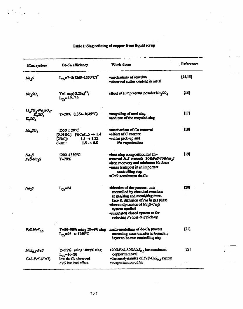
1uw)-13Hpc Y=7W
cfku of lmp - pOwd"a$O,
151

. . ~ . . -.
Table I: Slag rddag of copper hom Sqnid sarp (coatinfled)
152

153

-- w El a OI u u u w W M . d Z I
Fioue 5 - ~ffect of sodlu sulfide content on actlvlty coefficient of copper sulflde
00 I I I I I I I 00 0 , 0) a 04 OS 06 o?
W.rOd..1I@a
F I W ~ 6 - E f f e c t of sod im sulfide &tent on thc square root Of activity of iron sulfide
yd.v”d-uc1
Figure 7 - Effect of copper sulfide content on act iv i ty c a f f l c i e n t of copper sulfide
154

ClSR PROGRESS REPORT
Fundamentals of Decopperization from Solid Scrap
Y. Zhang, Research Associate
A. W. Cramb, Assoc. Professor
R. J. Fmehan, Professor
September 22,1989
INTRODUCTION
Steel can become contaminated by a number of non-ferrous metals which are present in the
various forms of scraps. Copper is a common contaminant and causes deleterious effects on certain
steel product properties. As conventional steelmaking processes cannot remove copper, researchers,
worldwide, are seeking a process to remove copper from steel scrap. At CMU, a procesi by which the
steel scrap is treated at 1000°C with a FeS-Na,Smatte to remove copper is under investigation.
Previous studies of the mechanism of removing copper from solid scrap using FeS-Na,S sulfide
matte[1-2-31 have highlighted the following facts:
*only about 10 kilograms of matte are needed to treat one ton of saap, which is
there is no need for carburization-decarburization or extensive desulfurization.
the treatment may not be conducted under an oxidizing atmosphere.
advantageous economically.
The concept of the method is that the affinity of Sfor Cu is greater that that for Fe at temperatures higher
that about 670°C. Therefore,
FeS + 2Cu = Cu$ + Fe
While the addition of N a 2 serves to make a liquid matte with FeS at temperatures even as low as 700°C
and improve the thermodynamics of copper remval by decreasing the activity coeffcient of C u g in the
matte.
155

CURRENT WORK
The objective of this study is to investigate the solid copper dissolution rate in the liquid sulfide
matte. This should help improve understanding of solid scrap decopperization and enhance large scale
experimental optimization.
To date, the following work has been accomplished:
m e experimental apparatus has been set up and initial experiments accomplished.
A method of preparing anhydrous N a g by Na+9H20 dehydration has been successfully
Experiments on the dissolution rate as a function of copper cylinder rotation speed has been
As the experimentai study being in progress, the mechanism of the solid copper being
developed.
completed.
dissolved by the liquid matte is under investigation.
EXPERIMENTAL
Fig.1 shows the experimental set-up. A carbon crucible 3cm In inner diameter and 9cm In height is
placed into the furnace. About 100 grams of FeS-NaS mixture were charged into the crucible through a
carbon funnel. A speed adjustable motor was mounted above the furnace. The commercial grade
copper cylinder, 1 5 a in length and of varying diameter, Is rotated In the melted matte by the motor. The
shaft connector between motor and the shaft which is attached to the copper cylinder also helps lower the
copper cylinder so as to start the reaction precisely at zero time. Argon gas is introduced at a flow rate of
2.5Vmin from the beginning of the experiment. During each run, matte samples are taken as a function of
time. Then they are kept in an air-pumped desiccator before being dissolved by nitric aad(5O percent in
volume). Na. Fe and Cu are analyzed by the atomic absorption method.
RESULTS
1. Dehydration of Na,S.SH,O __
Anhydrous N a s was prepared by dehydration of Na$SH& at temperatures below 300°C and
pressures between 3-3.5 mmHg. Efforts were made to avoid the hydrolysis reaction of the dried N a s and the decomposition of Nap was prevented by an adequate vacuum and by reducing the temperature
-
156

of the system to 200% after about three hours. Fig2 illustrates the operation pattern for Na+gH,O
dehydration. At late stages, the weight of the sample has been checked to determine the stoichiometry.
2. Solld copper dissolution rate In matte
As a preliminary step of study, the following conditions were set:
(l)FeSNa+50g/50g; (2)Copper cylinder diameter=lOmm;
(3)Temperature=900°C; (4)Rotation speed of copper cylinder-0,20,40 and 60rpm.
Liquid FeS-NaS matte had a height of 5.5cm in the crucible after melting. Its density was 3g/cm3.
The copper cylinder immersion depth was 4.5cm.
A typical result of solid copper dissolution rate In the liquid matte as a function of time is shown in
Fig.3. Copper cylinder rotation speed was 201pm. After about two and half hours, C u p content in matte
reached 30wPh. This is considered as approaching the equilibrium as predicted by I. Jimbo et a1[41 at
32wph. Ratio between the weight of initial FeS-Nas matte and the weight of removed copper(copper in
the matte phase) is about 4.1 7. FeScontent in matte reduced almost constantly as a function of time. At
the meantime, N a S behaved quite differently at different stages during the experiment. The extent of
decomposition of N a S at the beginning of the experiment accounted for the majority of the copper
dissolution. After about 30 minutes, Nasconcentration was constant. The overall reduction of the Na#
content in matte Is about 12wt%.
The effect ot copper cylinder rotation speed on the dissolution rate is shown in Fig.4. It does not
indicate that rotating the copper cylinder faster would result in a higher dissolution rate of copper. The
highest rate was obtained when the copper cylinder was rotated at 20rpm. lnaeasing the rotation speed
to 40rpm and 60rpm resulted in a decrease of the copper dissolution rate, however, FeSand N a s initial
concentrations in the case of rotation at 60rpm were not controlled accurately at 50wPh each. The
dissolution rate of copper into the liquid matte under the static condition (rotation speed=O) was almost
the same as that at 40rpm rotation speed. It is thus concluded that,
relative velocity between solid copper and liquid matte does not have significant influence on
the reaction between the liquid FeS-NaS matte and solid copper is quite complicated and
the dissolution rate of copper into the FeS-Nasmatte.
157

cannot be interpreted as simple m a s transfer control and topo-chemical reaction wntrol mechanism.
3. Prellmlnary observatlons on the reactlon mechanlm
After experimental runs, it was found that the part of copper cylinder that was immersed into the
matte was fully covered by a half-molten material, which could be dropped back to the crudbie by pulling
the cylinder out of the vessel and rotating it faster. Fig.5(a) shows an original copper cylinder and Fig.5(b)
shows the half-molten material.
The sticking materials obtained after the experiments at static condition and when rotation was at
20rpm speed have been analyzed for the average contents of Na. Fe and Cu elements. The table beiow
gives this result,
wt%Na wf%Fe W C U
0 rpm: 11.69 49.67 10.37
20 rpm: 10.58 48.22 20.17
I t is quite obvious that this material sticking to the copper cylinder contains mainly iron. But Na and Cu contents are less that those in the matte phase. This suggests that the sticking material hindered the
reaction by resisting the mass transfer of FeS from liquid phase to the vicinity of the unreacted solid
copper, and may explain that the rotation speed of copper cylinder has no significant effect on the
dissolutiin rate.
Attempts are underway to determine the concentration profiles of S, Na. f e and Cu along the
radius direction from the boundary of the unreacted solid copper to the edge of the sticking material by
SEM. - ~
In addition, Fig.5(c) shows clearly a quite uniform erosion of solid copper cylinder when it is rotated
during the experiments. Under the static condition. there is less dissolution of copper at the bottom which
suggests non-uniform distribution of the liquid matte composition along the copper cylinder.
-
158

FUTURE WORK
Future work will be concentrated on the following experiments:
dissolution rate as a function of initial matte composition;
dissolution rate and the equilibrium Cu;j concentration in matte as a function of
understand the reaction mechanism better and solve relevant problems.
temperature;
REFERENCES
1. R. J. Fruehan; A. W. Cramb, Removal of Copper from Scrap, Proposal to US Deparrmenf of €nergy, March 1, 1988
2. I. Jimbo; M. S. Sulsky and R. J. Fruehan, lron andSteelmaker, Aug.. 1988, pp20-23
3. L. Liao; A. W. Cramb and R. J. Fruehan. Refining of Copper from Solid Ferrous Scrap, ClSR progress Report, Feb.. 1989
4. I . Jimbo; M. S. Sulsky and R. J. Fruehan, P m . Philbrook Memorlal Symp. Conf., 1988, Pp133-144
159

M o t o r
S h a f t T
T h e r m o c o u p l e
Ar gas i n l e t
Fig.1 Experimental apparatus for testing the dissolution rate
of solid copper into liquid FeS-Na2S matte
160
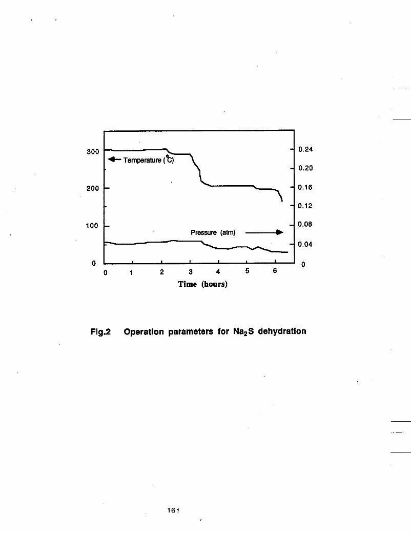
300
200
- 0.24
- 0.20
- - 0.16
- 4- Temperature (
300
. 1 0 . 1 2
1-7 4- Temperature (t)
100 t 200
4 0 . 0 8 Pressure (atm) 4
t I I I ‘ 0
0 1 2 3 4 5 6
Time (hours)
Fig9 Operation parameters for Na2S dehydration
161

Time (min)
Fig3 Solid copper dissolution rate as a function of time
162

I orpm I 50
40
30
20
10
0 - 0 20 40 60 80 100 120 140
Time (min)
Fig.4 Effect of copper cylinder rotation speed on reaction rate
163

a: copper cylinder before reaction
b: reacted portion covered by a half-molten material
c: qulte unlform erosion of copper along the reacted region
d: reacted under statlc condition
Fig.5 Preliminary observations on the reaction mechanism
1 6 4

ClSR PROGRESS REPORT
Fundamentals of Decopperization from Solid Scrap Y. Zhang, Research Associate A. W. Cramb, ASSOC. Professor
April 10,1990
R. J. FNehan, Prolessor
INTRODUCTION
Steel can become contaminated by a number of non-ferrous metals which are present in the
various forms of scraps. Copper is a common contaminant and causes detrimental effects on certain
steel product properties. As conventional steelmaking processes cannot remove copper, researchers.
worldwide, are seeking a process lo remove capper from sled scrap. At CMU, a process by which the
steel scrap is treated at 1000°Cwith a FeS-Nap matte to remove copper is under investlgation.
Previous studies of the mechanlsm of removing copper from solid scrap using FeS-Na3 sulfide
matte['2e31 have highlighted the following facts:
only about 10 kilograms of matte are needed to treat one tonne of scrap, which is
there is no need for carburization-decarburization or extensive desulfurization.
advantageous economically.
At temperatures greater than 670% C U ~ Is more stable that FeS. Thus copper will exchange with iron
if in contact with iron sulfide. The addition of N a p to FeS forms a liquid matte at temperatures even as
low as 7OO0C and improves the thermodynamics of copper removal by decreasing the activity coefficient
of C u p in the matte. Thus FeS-Nap mattes should react with solid copper.
The objective of this study is to investigate the klnetlcs and mechanism of the dissolution of solid
copper into a liquid FeS-Nap sulfirie mattes and therefore improve understanding of solid scrap
decoppperization and enhance large scale experimental optimization.
WORK TO DATE
165

To date the following work has been accomplished:
0 Initial experiments were carried out using FeS-NaS (50g508) matte14i.
A method of preparing anhydrous Nas by Na$.SH,O dehydration has been successfully developed.
A preliminary study on the klnetics of the dissolution of solid copper Into a liquid FeS-NaS matte has been completed. This includes the development of a theoretical model and experlments of the dissolutlon rate as a function of copper rotation speed.
Experiments on the equilibrium concentration of copper in the FeS-Na$(75g:25g) matte have been carried out.
SEM and microscopic obsewatlons have been used to study the mechanism of the process of solid copper dissolution into liquid matte.
EXPERIMENTAL
Fig.1 shows the experimental set-up. A graphite crucible 3cm in inner diameter and 9cm in height is
placed Into the furnace. 100 grams of FeS-NaS mlxlure are charged Into the crucible through a graphite
funnel. A speed adjustable motor is mounted above !he furnace. The commercial grade copper cylinder,
15cm in length and about l cm inner diameter, is rotated In the melted matte by a motor. The shaft
connector between the motor and the shaft, which is attached to the copper cyllnder, helps lower the
copper cylinder and start the reaction precisely at zero time. Argon gas is introduced at a flow rate of
2.5Umin from the beginning of the experiment. During each run, matte samples are taken as a function of
time. Then they are kept In an air-pumped desiccator before being dissolved by nitric acid (50 percent in
volume). Na, Fe and Cu are analyzed by the atomlc absorption method.
RESULTS AND DISCUSSIONS
1. Kinetics of copper dissolution In matte
Conditions of the experiments are as follows:
FeS-N@=758:258
copper cylinder diameter-10"
temperature=900°C
166

rotation speed of copper cylinder=O, 30, 50, 60, 90, 150, 200tpm
The depth of liquid FeS-Nap was 5.5 cm In the crucible. Its density was approximately 3g/cm3.
The copper cylinder was immersed Into the liquid, or that 4.5-4.8 cm of the cylinder was in contact with the
melt.
Fig.2 shows typical results of solid copper dissolution rate in the liquid matte FeS-Na#(75g:25g) as
a function of time. G u s content in matte increases as time Increases. The higher the copper cylinder
rotation speed, the faster the copper dissolution rate. Copper has a very high solubility in the liquid
FeS-Nap matte. By rotating two pieces of copper cylinder (changing a second one after the first copper
cylinder has wom out), the Cu concentration In matte was found to be 40%, which Is equivalent to a 50%
G u s content in matte in case that there is mlnlmal solubility In matte. In another experlment, FeS-Nas
(6g:2g) matte was melted in a copper cruclble at 9OOOC for 16 hours. Flnal Cu content In llquid matte
phase was 37%. which corresponds to a G u s content of about 46%.
Fig.3 gives the variation of FeS and N a s concentrations in matte as a fUnCtIOn of time. FeS
content in matte decreases as time Increases. According lo mass balance, weight percent of Nap in
matte decreases mainly because the dilution effect as FeS Is repiaced by G u s in matte.
Theoretically, supposing that the dissolution rate of solid copper is controlled by mass transfer of
Cu in liquid matte phase, we would have the following expression:
At zero time, copper content In liquid matte phase Is zero and the mass transfer coefficient kd can be
solved by
if copper dissolution is controlled by mass transfer of Cu In liquid matte phase, kd calculated above should
obey the relationship thatlq ___
kd = 0.0791 (Re)‘.- (SC)‘.~ (3 )
In case that the initial diameter of the copper cylinder is the same in each experiment, ~
167

where A is a constant,
2ro 4.30 A = 0.0791 [-] ( S C ) ~ . ~
V
Fig.4 shows the relationship of the calculated &,, from Eq.(2) with the rotation speed of the copper
cylinder assuming mass transfer control mechanism. Thus this relationship is consistent with the
theoretical relationship of mass transfer control mechanism when the rotation speed is greater that 90
rpm. At lower rotation speeds, mass transfer of Cu in liquid matte is not the rate limning step. When
uslng higher N a s content (50%) in matte, the results of low rotation sped (even at 60rpm) were
observed to have even larger deviation from mass transfer control mechanism as shown in Fig.5.
__
Fig.6 shows the typical observations of the reacted copper cylinder. At lower rotation speeds, the
reacted portion of the copper cylinder was covered by a layer of hail-molten material (FigSb), this formed
a barrier for mass transfer and thus hindered the reaction. But at higher rotallon speed, lhe sticking layer
did not form around the copper cylinder and was found to settle to the bottom of Ule crucible. Thus under
high rotation speeds, there exists a very dear Interface beween the liquid matte and the solid copper
(Fig.&). In addltion, when a higher Na;s content Is used, a more stable stidcing layer around the copper
cylinder Is formed and thus retards the reaction rate.
Eq(1) can also be Integrated over time. From mass balance, I can be estimated that,
Then we have,
where,
168
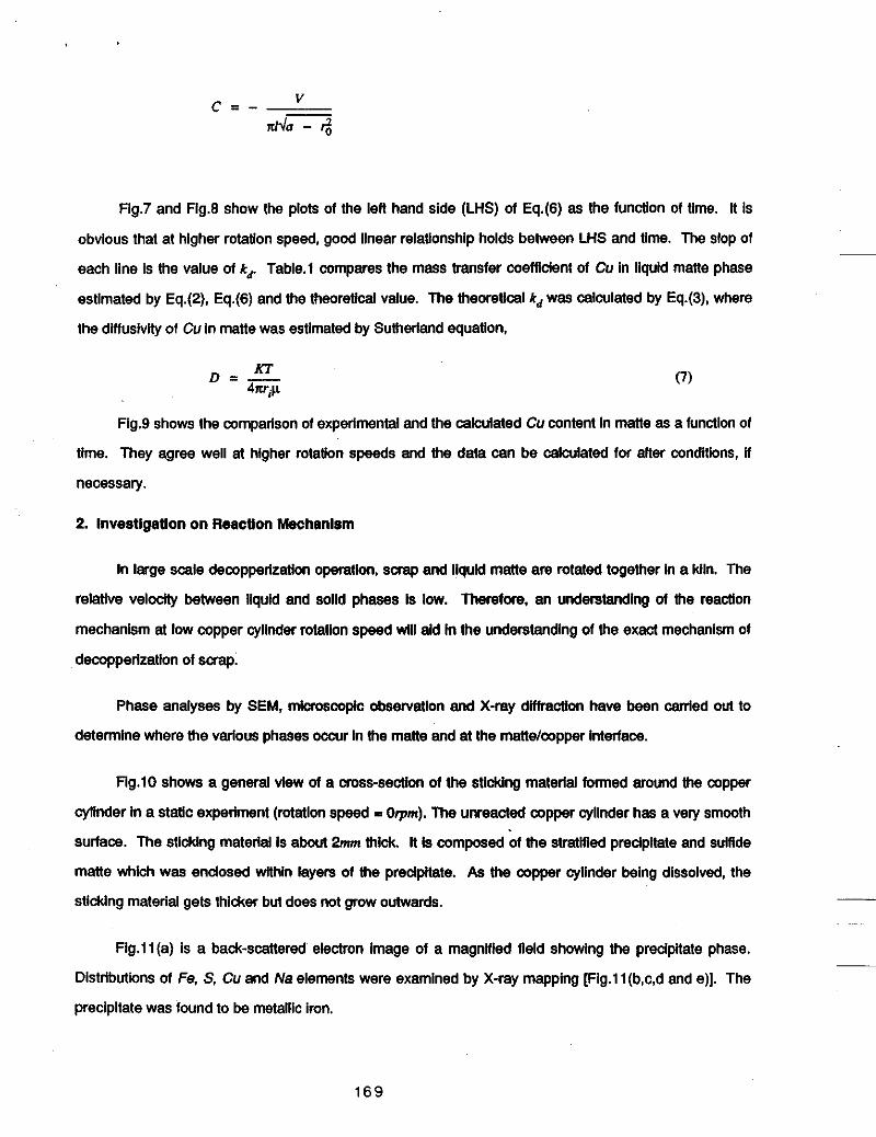
Fig.7 and Fig.8 show the plots of the left hand side (LHS) of Eq.(6) as the function of time. it is
obvious that at higher rotation speed, good linear relationship holds between LHS and time. The slop of
each line is the value of k6 Table.1 compares the mass transfer coefficient of Cu in liquid matte phase
estimated by Eq.(2). Eq.(6) and the theoretical value. The theoretical kd was calculated by Eq.(3), where
the diffusivity of Cu in matte was estimated by Sutheriand equation,
Fig.9 shows the comparison of experimental and the calculated Cu content in matte as a function of
time. They agree well at higher rotation speeds and the data can be calculated for alter conditions, if
necessary.
2. lnvestigatlon on Reaction Mechanism
in large scale decopperization operation, scrap and liquid matte are rotated together in a kiln. The
relative veiodly between liquid and solid phases is low. Therefore, an understanding of the reactlon
mechanism at low copper cylinder rotation speed will aid in the understanding of the exact mechanism of
decopperization of scrap.
Phase analyses by SEM, microscopic observation and X-ray dntraction have been canied out to
determine where the various phases occvr in the matte and at the matte/copper interface.
Flg.10 shows a general view of a cross-section of the sticking material formed around the copper
cylinder in a statlc experiment (rotation speed I Otpm). The unreacted copper cylinder has a very smooth
surface. The sticking material is about 2" thick. it is composed of the stratified precipitate and sulfide
matte which was enclosed within layers of !he precipitate. As the copper cylinder being dissolved, the
sticking material gets thicker but does not grow outwards.
Fig.ll(a) is a back-scattered electron image of a magnified fleid showing the precipitate phase.
Distributions of Fe. S, Cu and Na elements were examined by X-ray mapping [Fig.l l(b,c,d and e)]. The
precipitate was found to be metallic iron.
169

Small pieces of copper were found in the Vicinity of the copper cylinder. Fig.lZ(a) shows a very
small copper piece with an imeguiar shape which was found in the mane phase of the sticking material.
Fig.lZ(b) and (c) show the distribution of Cu and S in the field of observation.
it was also found that inside the solid copper cylinder, a thin layer of copper sulfide was formed
(about 0.5mm from the interface). Fig.ll(a) shows the foreign phase inside the near-interface region of
the solid copper cylinder. Fig.l3(b) and (c) show distributions of Sand Cu elements. This suggests that
sulfur may have dmusad into the solid copper cylinder. although the details of this need further
investigation.
Once the major phases in the system were Mentifled. optical observations were made. Spedal
efforts were taken during preparation of the specimen to prevent sample degradation as the sulRde
absorbs water from the atmosphere. b ?
From Fig.14 it can be seen that F 8 did not nucleate vely close to the copper cylinder, but at a
small distance (about 0.2-0.3”) away from It. Close to the cylinder, there is much less Fe nucleation,
while copper with a relatively small size distribution can be found. Fig.15 shows some detailed
observations at the interface between the copper cylinder and the matte phase in the sticking material.
There is evidence that small copper pieces break off from the copper cylinder in these observations.
Fig.l6(a) and (b) show the morphology of the copper suifide phase in the copper cylinder in two
dimensions. Its shape Is much like that of a thin scale. It is believed that Me formation of this copper
sulfide phase inside the copper cylinder caused small copper pieces break oft from It.
Fig.17 shows the observations on the mane phase (cooled In air) fat a horizontal cross-section of
the crucible. Fig.l7(a) shows the matte phase, its morphology was formed depending on the coding
direction. Rg.l7(b) was taken at a higher magnification. Metallic iron inclusions were scatrered in the
matte. These F 8 inclusions are considered to precipitate during soldificetion or as a result of reaction In
solid statelel. Therefore it is reasonable to assume that there is no Feo or Cd’ in bulk matte phase in
chemical analysis. __
~
SUMMARY
1. At low copper cylinder rotation speed, a layer of half-molten sticWng material was formed around
1 7 0

the unreacted copper rod in place of the reacted copper. in this case, reaction mechanism was found to
be complicated. At high copper cylinder rotation speed, the precipitate settled to the bottom of the
crucible and there existed a clear interface between solid copper and liquid matte. It has been lound that
the mass transfer of Cu in matte phase (from interface to bulk region) is the rate-controlling step. Mass
transfer coefficient of Cu in matte was evaluated.
2. At 900°C, equilibrium content of Cu In liquid FeS-Na+(Cus) phase would be up to 37-40%.
Equilibrium experiments showed no significant Na evaporation.
3. A theoretical expression for copper dissolution from a rotating copper cylinder into the liquid
matte was proposed based on that mass transfer of Cu in liquid matte is the rate-controlling step. The
calculated results can explain the experimental ones of higher copper cylinder rotation speed.
4. SEM X-ray mapping method was used and metallic Fe, Cu phases in the sticidng material and
copper sulfide phase in the solid copper cylinder have been identified.
At the static condition, layers of solid metallic iron precipitates around the copper rod and encloses
very thin layers of sulfide matte, and therefore sticks to the copper cylinder firmly and forms a barrier for
mass transfer.
Reaction mechanism is very complicated. interiadai reaction between solid copper and matte
needs further study. And lt is obvious that S dMfuses into the solid Cu forming copper sulfide and breaks
small pieces of solid copper into matte so that the kinetics of the pmcass is enhanced.
REFERENCES
1. R.J. Fruehan; A.W. Cramb, Removal of Copper from Scrap, Proposal to US Department of
2.1. Jimbo; M.S. Sulsky and R.J. Fruehan. Iron and Sfeelmaker. Aug.. 1988, pp20-23
3. I. Jimbo; M.S. Suisky and R.J. Fruehan. P m . PhiIbmok Memorial S y q . Conf., 1988.
4. Y. Zhang; A.W. Cramb and R.J. Fruehan, CISR Progress Report, Sept.22.1989
5. M. Eisenberg; C.W.Tob1asandC.R. Wiike, Chem. Eng. Prog. Symp., No.16, 1955, p1
E new, March 1,1988
ppl33-144
6. R.W. Ruddie, Physlcal Chemisffy of Copper SmeMng, inst. of Mining & Metail., London, 1953
1 7 1
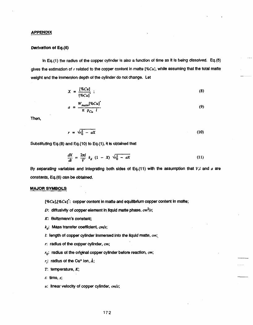
APPENDIX
Derlvation of Eq.(6)
in Eq.(l) the radius of the copper cylinder is also a function of time as it is being dissolved. Eq.(5)
gives the estimation of r related to the copper content in matte [%CUI, while assuming that the total matle
weight and the immersion depth of the cylinder do not change. Let __
Then,
r = d + - d
Substituting Eq.(B) and Eq.(lO) to Eq.(l), il is obtained that
dX 2n1 - E - kd (1 - X ) 44 - O X a l v By separating variables and integrating both sides of Eq.(ll) with the assumption that V,l and a are
constants, Eq.(6) can be obtalned.
MAJOR SYMBOLS
[%Cu],[%Cu]’: copper content in matte and equilibrium copper content In matte;
D: diffuslvity of copper element in liquid matte phase, em%;
K: Boikmann’s constant;
kd: Mass transfer coefficient, 4 s ;
I : length of copper cylinder immersed into Ihe liquid malle, cm;,
r: radius of the copper cylinder, cm;
ro: radius of the original copper cylinder before reaction, on;
r; radius of the Cu+ ion, A; T: temperature, K;
t: time, S;
u: linear velocity of copper cylinder, c d s ;
172

V: total volume of liquid matte phase, em3;
Wd,e: weight of liquid matte, g;
p: viscosity of liquid matte, g/cms;
v: dynamic viscosity of liquid matte, em%;
pcu: density of solid copper, &m3.
1 7 3

Table.1 comparison of mass transfer coefficients by different estimations

h l o t o r
S h a f t T
Ar gas II i n l e t
T h e r ni oca u p I e Y- Fig.1 .Experimental apparatus for testing the dissolution rate
of solid copper into liquid FeS-Na,S matte
175

6 0
5 0
4 0
5i 3” s 0 30
Y s 2 0
1 0
0 1 0 5 120 3 0 45 6 0 7 5 9 0
Time (min)
0 1 5
Fig.2 Concentration of Cu 2 S in matte as a function of time.
176

80
6 0
- - :: g
4 0
2 0
I I I I 0
0 2 0 4 0 6 0 8 0 100 1 2 0
Time( min)
Fig.3 Concentrations of FeS and Na2S in matte as a function
of time.
177

-2.3
- 2 . 5
-2 .7
2 0) -2.9 0 -
-3.1
-3.3
-3.5
Fig.4 Comparison of the experimental results of the coefficient
k theoretical relationship kd=A'u .
assuming mass transfer control mechanism with the 0.7 d

-2.3
. ' -2 .5
-2.7
-3.1
-3.3
-3 .5
Fig.5 Observation on the reaction mechanism when using the
matte with higher NaZS content.
179
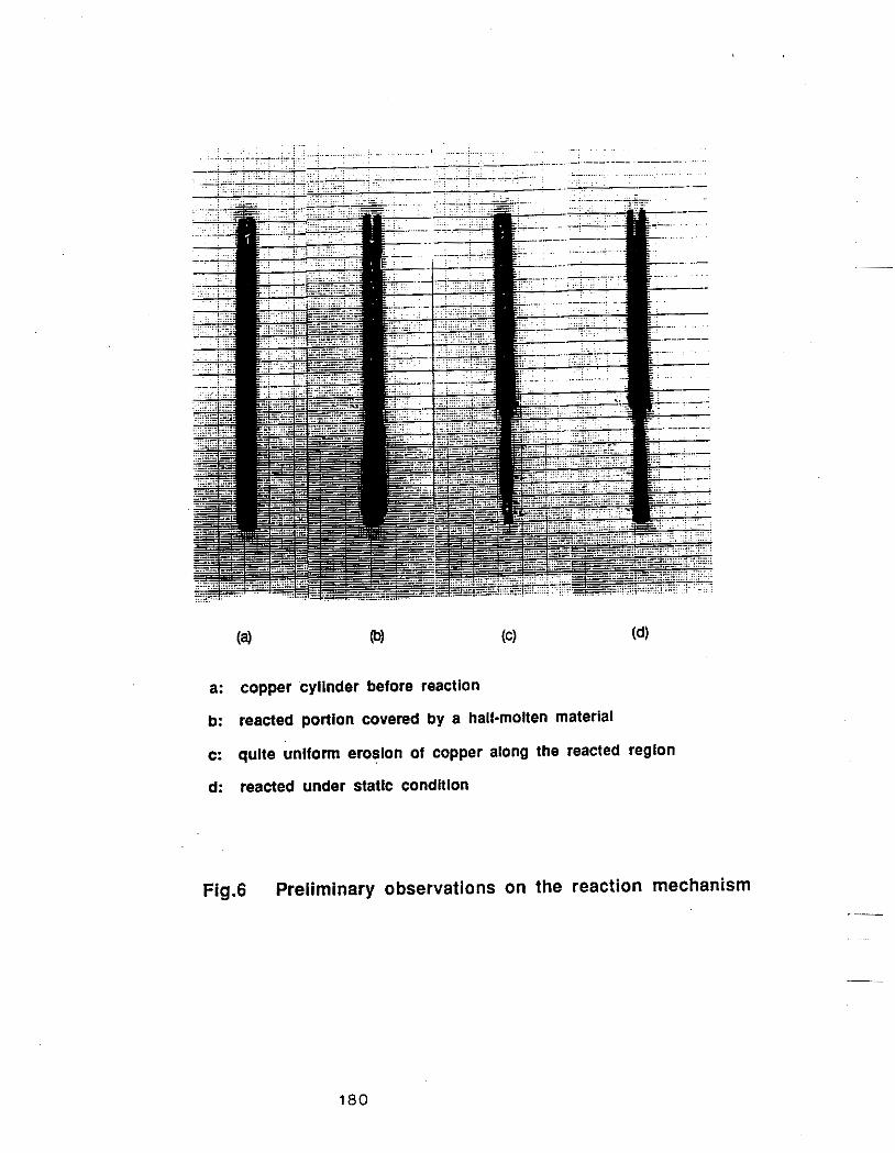
a: copper cylinder before reaction
b: reacted portion covered by a hail-molten material
c: quite uniform erosion of copper along the reacted region
d: reacted under static condition
Fig.6 Preliminary observations on the reaction mechanism
180

-0.04 I I I I I
A orpm 0 o 30rpm - 0
-0.05 - -
3 - 5 -0.06 - w l i
0 (I)
- - - 3 -0.07 - 0
- - A
0
A - -
-0.08 -
I I I I I -0.09
0
A A
Fig.7 Plot of the left-hand side of eq.(6) as a function of
time on the data of low revolution speed.
. i
181

-0.01
-0.03
z- - -0 .05 ci
W 0 cn 3 -0.07
..-
-0.09
-0.1 1 0 1 0 20 30 4 0 5 0 60
Time (min)
Fig.8 Plot of the left-hand side of eq.(6) as a function of time on the data of high revolution speed.
182

Time (min)
Fig.9 Comparison of experimental data with the calculated
values.
183

Fig.10 Sticking material around the unreacted copper cylinder (the arrow points where the magnification of Fig.9 was taken)
184

Fig.1 l(a) Back-scattered Electron image of a maginified field showing the precipitate phase
Fig.1 l(b) Distribution of Fe element by X-ray mapping
185

Fig.1 l(c) Distribution of S element by X-ray mapping
Fig.1 l(d) Distribution of Cu element by X-ray mapping
186

Fig1 l(e) Distribution of Na element by X-ray mapping
187

Fig. 12(a) Back-scattered Electron image of a piece of copper in the sticking material near the copper rod

Fig.l2(b) Distribution of Cu element by X-ray mapping
Fig.l2(c) Distribution of S element by X-ray mapping
189

Fig.l3(a) Back-scattered Electron image of copper sulfide phase in the boundary layer of copper rod
1 9 0

Fig.l3(b) Distribution of S element by X-ray mapping
Fig.l3(c) Distribution of Cu element by X-ray mapping
191

COPP rod
Fig.14 Fe nucleation around the copper cylinder (magnification 200x)
1 9 2

:OPI :od
QPF rod
193
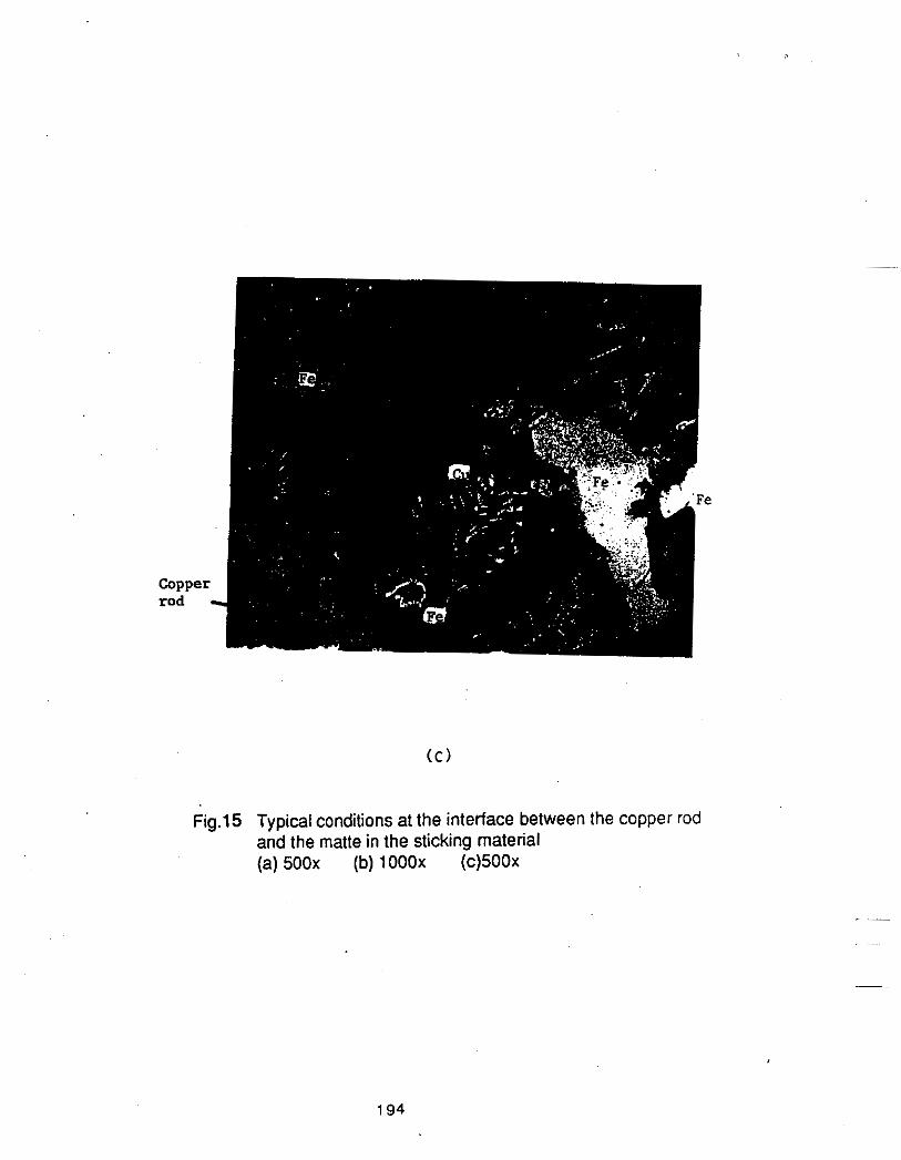
coppel rod
Fig.15 Typical conditions at the interface between the copper rod and the matte in the sticking material (a) 500x (b) 1 OOOx (c)500x
194

4
' , 'bpper . .
I ' .rod, ., [, ;. 1. . _ .. . . . . . ... . ., . .' . '. ' .I
.
(b)
Fig.16 Formation of copper sulfide phase in the boundary layer of copper rod (a) horizontal cross-section; 1 OOx (b) longitudinal cross-section: 200x
195

(b)
Fig.17 Microscopic observation on the matte phase (a) horizontal cross-section of crucible;ZOOx (b) scattered small iron phase; 1OOOx
196