
Cooling Photovoltaic Thermal Solar Panel by Using Heat Pipe at...
15
International Journal of Mechanical & Mechatronics Engineering IJMME-IJENS Vol:17 No:06 171 I J E N S IJENS © December 2017 IJENS - IJMME - 9595 - 06 1733 Cooling Photovoltaic Thermal Solar Panel by Using Heat Pipe at Baghdad Climate Laith Jaafer Habeeb 1 , Dheya Ghanim Mutasher 2 , Faez Abid Muslim Abd Ali 3 1,2 University of Technology, Mechanical Engineering Department College University of Kufa, Engineering 3 [email protected] Abstract-- This paper represents an experimental investigation of cooling the photovoltaic panel by using heat pipe. The test rig is constructed from photovoltaic panel with dimension (1200×540) mm with 0.07 mm thickness copper plate base, four thermosyphon heat pipes with 55% distilled water filing ratio and water box heat exchanger with a capacity of 16.2 litter. The novel panel compared with the traditional panel, the panels are installed south direction on months tilt angle. The experiments are carried out o and 45 April, May and July in 2017, Baghdad, the test begins at 8:00 a.m. till 14:00 p.m. In the theoretical investigation, the theoretical model consists of two parts; in the first part, an electrical equation is applied to find electrical characteristics while in the second part, heat balance equations are achieved to find thermal characteristics to the whole domain. A MATLAB program is used to compute the model and establishing characteristic curves. The experimental thermal result proved that, the novel method is successful in cooling the solar panel and that the module is colder than traditional panel in a rate of (15-35) % and the electrical efficiency are improved by (11-14) % and theoretical results revealed good agreement with a small deviation of about (3-6) %. Index Term-- Cooling photovoltaic panel, thermosyphon heat pipe. NOMENCLATURE ‒‒‒‒ Curve-fitting parameter for the four-parameter model a ‒‒‒‒ Curve-fitting parameter for the four-parameter model at reference condition ref a 2 m Module area A J Energy-band gap q E 2 W/m Solar irradiance intensity G 2 W/m Solar irradiance at reference condition ref G A Current of the module I A Light-generated current L I A Light-generated current at reference condition L,ref I A Current at maximum-power point mp I A Current at maximum-power point at reference condition mp,ref I A Diode reverse saturation-current o I A Diode reverse saturation-current at reference condition o,ref I A Short-circuit current sc I A Short-circuit current at reference condition sc,ref I ‒‒‒‒ Number of cells in series in one module S N W Power at maximum-power point mp P Coulomb Electron charge (1.60218×10 -19 ) q Ω Series resistance S R Ω Series resistance at reference condition s,ref R Ω Shunt resistance sh R K Cell temperature c T K Cell temperature at reference condition c,ref T V Voltage of the module V V Voltage at maximum-power point mp V V Voltage at maximum-power point at reference condition mp,ref V V Open-circuit voltage oc V V Open-circuit voltage at reference condition oc,ref V ‒‒‒‒ Efficiency of the module at maximum-power point V/K Temperature coefficient of open-circuit voltage ˌ A/K Temperature coefficient of reference current ˌ
Transcript of Cooling Photovoltaic Thermal Solar Panel by Using Heat Pipe at...
International Journal of Mechanical & Mechatronics Engineering IJMME-IJENS Vol:17 No:06 171
I J E N SIJENS © December 2017 IJENS -IJMME-9595-061733
Cooling Photovoltaic Thermal Solar Panel by Using
Heat Pipe at Baghdad Climate
Laith Jaafer Habeeb1, Dheya Ghanim Mutasher 2, Faez Abid Muslim Abd Ali3 1,2 University of Technology, Mechanical Engineering Department
College University of Kufa, Engineering3 [email protected]
Abstract-- This paper represents an experimental investigation
of cooling the photovoltaic panel by using heat pipe. The test rig is
constructed from photovoltaic panel with dimension (1200×540)
mm with 0.07 mm thickness copper plate base, four thermosyphon
heat pipes with 55% distilled water filing ratio and water box heat
exchanger with a capacity of 16.2 litter. The novel panel compared
with the traditional panel, the panels are installed south direction
on months tilt angle. The experiments are carried out oand 45
April, May and July in 2017, Baghdad, the test begins at 8:00 a.m.
till 14:00 p.m. In the theoretical investigation, the theoretical
model consists of two parts; in the first part, an electrical equation
is applied to find electrical characteristics while in the second part,
heat balance equations are achieved to find thermal
characteristics to the whole domain. A MATLAB program is used
to compute the model and establishing characteristic curves. The
experimental thermal result proved that, the novel method is
successful in cooling the solar panel and that the module is colder
than traditional panel in a rate of (15-35) % and the electrical
efficiency are improved by (11-14) % and theoretical results
revealed good agreement with a small deviation of about (3-6) %.
Index Term-- Cooling photovoltaic panel, thermosyphon heat
pipe.
NOMENCLATURE
‒‒‒‒ Curve-fitting parameter for the four-parameter model a
‒‒‒‒ Curve-fitting parameter for the four-parameter model at reference condition refa 2m Module area A
J Energy-band gap qE 2W/m Solar irradiance intensity G 2W/m Solar irradiance at reference condition refG
A Current of the module I A Light-generated current LI
A Light-generated current at reference condition L,refI
A Current at maximum-power point mpI
A Current at maximum-power point at reference condition mp,refI A Diode reverse saturation-current oI
A Diode reverse saturation-current at reference condition o,refI A Short-circuit current scI
A Short-circuit current at reference condition sc,refI
‒‒‒‒ Number of cells in series in one module SN
W Power at maximum-power point mpP Coulomb Electron charge (1.60218×10⁻¹⁹) q
Ω Series resistance SR
Ω Series resistance at reference condition s,refR Ω Shunt resistance shR
K Cell temperature cT
K Cell temperature at reference condition c,refT V Voltage of the module V
V Voltage at maximum-power point mpV
V Voltage at maximum-power point at reference condition mp,refV
V Open-circuit voltage ocV
V Open-circuit voltage at reference condition oc,refV ‒‒‒‒ Efficiency of the module at maximum-power point 𝜂 V/K Temperature coefficient of open-circuit voltage 𝜇𝑉ˌ𝑜𝑐
A/K Temperature coefficient of reference current 𝜇𝐼ˌ𝑟𝑒𝑓

International Journal of Mechanical & Mechatronics Engineering IJMME-IJENS Vol:17 No:06 172
I J E N SIJENS © December 2017 IJENS -IJMME-9595-061733
1. INTRODUCTION
Solar energy presents the main source of energy for life on
earth, and for humans’ development. It is not only that the
sunlight conversion into electricity or heat is essential for
various applications, but also a reliable storage of the sunlight
converted energy is highly useful since many applications
require storing the harvested solar energy to meet certain
consumption pattern [1]. Electrical energy, mostly because of
its ability to be easily transferred to work, is more valuable than
thermal energy. The most efficient way to obtain electrical
energy is from direct solar irradiance via photovoltaic cells (PV
cells). Although the overall efficiency of PV cells ranges from
about 5% - 20%, it is still higher than the total indirect
efficiency when it comes to wind and biomass efficiency.
However, it has been shown that the overall efficiency of
photovoltaic cells drops drastically with an increase in
temperature. The rate of decrease ranges from 0.25% to 0.5%
per degree Celsius, depending on the cell material used [2].
Akbarzadeh and Wadowski [3] introduced a passive method
based on thermosiphons which can effectively cool the
Photovoltaic cells under concentrated light. A prototype of an
east-west trough solar concentrator using the profile developed
for the reflecting surface, and incorporating a thermosiphon
cooling system for the photovoltaic cells, has been
manufactured and successfully tested. Tonui et al. [4] studied
the photovoltaic/thermal (PV/T) solar collectors with heat
extraction by forced or natural air circulation, air-cooling, either
by forced or natural flow, prepare a non-expensive and simple
method of photovoltaic panel cooling and the solar preheated
air could be used in manufactured, industrial and agricultural
section. William et al. [5] wrote a research about heat pipe
cooling of Concentrating Photovoltaic (CPV) systems, this
work successfully demonstrated the feasibility of a heat pipe
cooling solution for concentrating photovoltaic cells. Heat
pipes can be used to passively remove the heat, accepting a high
heat flux at the CPV cell, and rejecting the heat to fins by
natural convection. Tang et al. [6] studied experimentally the
micro heat pipe arrangement to cooling photovoltaic panel, air-
cooling and water-cooling, the temperature of cell can be
reduced to effectively increase the photoelectric conversion
efficiency of solar panel. The temperature decreases by 4.7 oC
and output power increases by 8.4%, for air-cooling compared
with ordinary solar panel and the temperature decreases by 8 oC
and output power increases by 13.9 % for water-cooling.
Souliotis et al. [7] studied the design and operation the
thermosyphon hybrid photovoltaic thermal solar systems, the
operating temperature of photovoltaic modules is reduced,
which is favorable, as it keeps their electrical efficiency at an
enough level. the experimental results of the outdoors tests
showed that thermosyphon type of PV/T systems can provide
both hot water and electricity for domestic applications with an
acceptable efficiency. Raj et al. [8] made an experimental study
on the performance of concentrated photovoltaic system with
cooling system for domestic applications, the cooling system is
component from heat pipe named Pulsating heat pipes. It has
been found that the electrical output of the water cooled CPV is
4.7 to 5.2 times more than the photovoltaic module without
concentration and cooling system. Hughes et al. [9] made a
computational study of improving the efficiency of
photovoltaic panels, this study focused on the performance of a
finned heat pipe assembled onto the rear of a photovoltaic panel
analyzed using CFD. They proposed and analyzed to determine
the improved heat dissipation and thus get better performance
efficiency of the photovoltaic panel. A prototype of the
arrangement is constructed for experimental testing to prove the
CFD modeling and proof of concept. Mutombo [10] present
study about the behavior of thermosyphon hybrid photovoltaic
thermal (PV/T) when exposed to differences of environmental
parameters and to prove the advantage of cooling photovoltaic
modules using a rectangular channel shape with water for the
thermal collector. The simulation result showed that the overall
efficiency of the PV/T module was 38.7% against 14.6% for a
standard PV module while the water temperature in the storage
tank reached 37.1 oC. This is a great reassurance to the
marketing of the hybrid photovoltaic thermal technology in
South Africa particularly during summer.
The present work is concerned with carrying out
experimental study and mathematical verification to study the
performance of photovoltaic panel by using heat pipe by
inventing a new technique to increase the conduction heat
transfer by using a copper plate to increase the thermal
conduction surface area from the panel to the heat pipe. Also,
coupled electrical and thermal model for calculating various
parameters related to the performance of photovoltaic cooling
by heat pipe system is developed and solving equations of the
problem numerically for all parts and determine PV model
parameters.
2.1. Heat Pipe Photovoltaic Module HP-PV/T The experimental setup, shown in Fig. (1), has been
designed and manufactured in this work. Schematic diagram of
the experimental rig with measurement devises and
thermocouples location are shown in Fig. (2) A and B
respectively.

International Journal of Mechanical & Mechatronics Engineering IJMME-IJENS Vol:17 No:06 173
I J E N SIJENS © December 2017 IJENS -IJMME-9595-061733
Fig. 1. Experimental setup system with measuring device.
Fig. 2. A: Schematic diagram of the experimental setup.

International Journal of Mechanical & Mechatronics Engineering IJMME-IJENS Vol:17 No:06 174
I J E N SIJENS © December 2017 IJENS -IJMME-9595-061733
Fig. 2. B: Schematic diagram of thermocouples location.
There are two photovoltaic panels used in the experimental
work (solar module panel and a traditional panel to compare
with), there were made of monocrystalline solar module 80(72)
M1240×541. The specifications of photovoltaic panels are
given in table (1), these are provided by the manufacturer for
the reference conditions of 1000 W/m2 of irradiance level, 25 oC of cell temperature.
Table I
Electrical characteristics data of the used solar module.
Four thermosyphon heat pipe manually making from copper
(14 mm) inner diameter, (16 mm) outer diameter and (1200
mm) evaporator length with filing ratio 55% distil water
working fluid, fitted on the back surface of the PV module. The
heat pipes and panel were covered from the back by a copper
plate 0.07 mm thickness, the new technique was done by
envelope around the heat pipe to increase the contact surface
Fig. (3); the system was insulated from the back of the panel by
50 mm glass wool. Condenser dimensions, with inner diameter
of 28 mm, outer diameter of 30 mm, and length of 150 mm
immersed at (540×150×300) mm3 water box Fig. (4). The space
between the two adjacent heat pipes were measured to be
approximately140 mm.
Specifications of PV Module GF 80C GRUNDFOS Model
80 W Peak Power (Pmax) 72 W Warranted Minimum Pmax
33.3 V Voltage at Maximum Power (Vmp)
2.4 A Current at Maximum Power (Imp)
41.5 V Open Circuit Voltage (Voc)
2.6 A Short Circuit Current (Isc)
68 (4×17) Total Number of Cells
(1200×541×35) mm Module Dimension

International Journal of Mechanical & Mechatronics Engineering IJMME-IJENS Vol:17 No:06 175
I J E N SIJENS © December 2017 IJENS -IJMME-9595-061733
Fig. 3. copper plate with heat pipe in the back of panel.
Fig. 4. water box with condensers.
3. MATHEMATICAL MODEL
A valuation of the operation of solar cells and the design of
power systems based on solar cells must be founded on the
electrical characteristics, the current voltage relationships of the
cells at various cell temperatures and under various levels of
radiation. For system design purposes, the model must offer the
means to calculate voltage, current, and power relationships of
cell arrays over the range of operating conditions to be
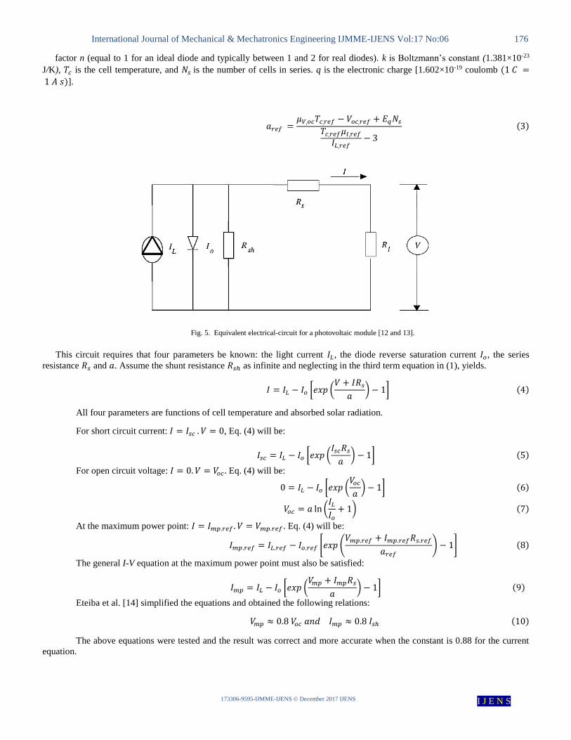
encountered. Fig. (5) is an equivalent circuit that can be used
for an individual cell, a module consisting of several cells, or
an array consisting of several modules [11 and 12]. At a fixed
temperature and solar radiation, the I-V characteristic of this
model is given by:
𝐼 = 𝐼𝐿 − 𝐼𝐷 − 𝐼𝑠ℎ = 𝐼𝐿 − 𝐼𝑜 [𝑒𝑥𝑝 (𝑉 + 𝐼𝑅𝑠
𝑎) − 1] −
𝑉 + 𝐼𝑅𝑠
𝑅𝑠ℎ
(1)
𝑎 is a parameter depending on the cell temperature calculated by:
𝑎 ≡𝑛𝑘𝑇𝑐𝑁𝑠
𝑞 (2)
International Journal of Mechanical & Mechatronics Engineering IJMME-IJENS Vol:17 No:06 176
I J E N SIJENS © December 2017 IJENS -IJMME-9595-061733
factor n (equal to 1 for an ideal diode and typically between 1 and 2 for real diodes). k is Boltzmann’s constant (1.381×10⁻²³
J/K), 𝑇𝑐 is the cell temperature, and 𝑁𝑠 is the number of cells in series. q is the electronic charge [1.602×10⁻¹⁹ coulomb (1 𝐶 =
1 𝐴 𝑠)].
𝑎𝑟𝑒𝑓 =𝜇𝑉ˌ𝑜𝑐𝑇𝑐ˌ𝑟𝑒𝑓 − 𝑉𝑜𝑐ˌ𝑟𝑒𝑓 + 𝐸𝑞𝑁𝑠
𝑇𝑐ˌ𝑟𝑒𝑓𝜇𝐼ˌ𝑟𝑒𝑓
𝐼𝐿ˌ𝑟𝑒𝑓− 3
(3)
Fig. 5. Equivalent electrical-circuit for a photovoltaic module [12 and 13].
This circuit requires that four parameters be known: the light current 𝐼𝐿 , the diode reverse saturation current 𝐼𝑜, the series
resistance 𝑅𝑠 and 𝑎. Assume the shunt resistance 𝑅𝑠ℎ as infinite and neglecting in the third term equation in (1), yields.
𝐼 = 𝐼𝐿 − 𝐼𝑜 [𝑒𝑥𝑝 (𝑉 + 𝐼𝑅𝑠
𝑎) − 1] (4)
All four parameters are functions of cell temperature and absorbed solar radiation.
For short circuit current: 𝐼 = 𝐼𝑠𝑐 . 𝑉 = 0, Eq. (4) will be:
𝐼𝑠𝑐 = 𝐼𝐿 − 𝐼𝑜 [𝑒𝑥𝑝 (𝐼𝑠𝑐𝑅𝑠
𝑎) − 1] (5)
For open circuit voltage: 𝐼 = 0. 𝑉 = 𝑉𝑜𝑐 . Eq. (4) will be:
0 = 𝐼𝐿 − 𝐼𝑜 [𝑒𝑥𝑝 (𝑉𝑜𝑐
𝑎) − 1] (6)
𝑉𝑜𝑐 = 𝑎 ln (𝐼𝐿
𝐼𝑜
+ 1) (7)
At the maximum power point: 𝐼 = 𝐼𝑚𝑝.𝑟𝑒𝑓 . 𝑉 = 𝑉𝑚𝑝.𝑟𝑒𝑓 . Eq. (4) will be:
𝐼𝑚𝑝.𝑟𝑒𝑓 = 𝐼𝐿.𝑟𝑒𝑓 − 𝐼𝑜.𝑟𝑒𝑓 [𝑒𝑥𝑝 (𝑉𝑚𝑝.𝑟𝑒𝑓 + 𝐼𝑚𝑝.𝑟𝑒𝑓𝑅𝑠.𝑟𝑒𝑓
𝑎𝑟𝑒𝑓
) − 1] (8)
The general I-V equation at the maximum power point must also be satisfied:
𝐼𝑚𝑝 = 𝐼𝐿 − 𝐼𝑜 [𝑒𝑥𝑝 (𝑉𝑚𝑝 + 𝐼𝑚𝑝𝑅𝑠
𝑎) − 1] (9)
Eteiba et al. [14] simplified the equations and obtained the following relations:
𝑉𝑚𝑝 ≈ 0.8 𝑉𝑜𝑐 𝑎𝑛𝑑 𝐼𝑚𝑝 ≈ 0.8 𝐼𝑠ℎ (10)
The above equations were tested and the result was correct and more accurate when the constant is 0.88 for the current
equation.

International Journal of Mechanical & Mechatronics Engineering IJMME-IJENS Vol:17 No:06 177
I J E N SIJENS © December 2017 IJENS -IJMME-9595-061733
𝑅𝑠 is assumed to be independent of both temperature and solar radiation so that:
𝑅𝑠 = 𝑅𝑠ˌ𝑟𝑒𝑓
𝑅𝑠ˌ𝑟𝑒𝑓 is calculated as:
𝑅𝑠ˌ𝑟𝑒𝑓 =
𝑎𝑟𝑒𝑓 ln (1 −𝐼𝑚𝑃ˌ𝑟𝑒𝑓
𝐼𝐿ˌ𝑟𝑒𝑓) − 𝑉𝑚𝑝ˌ𝑟𝑒𝑓 + 𝑉𝑂𝐶ˌ𝑟𝑒𝑓
𝐼𝑚𝑃ˌ𝑟𝑒𝑓
(11)
𝐼𝐿ˌ𝑟𝑒𝑓=𝐼𝑠𝑐ˌ𝑟𝑒𝑓
𝑇𝑐ˌ𝑟𝑒𝑓 = 298 (𝐾)
The light current 𝐼𝐿 for any operating conditions is related to the light current at reference conditions by:
𝐼𝐿 =𝐺
𝐺𝑟𝑒𝑓
[𝐼𝐿ˌ𝑟𝑒𝑓 + 𝜇𝐼ˌ𝑟𝑒𝑓(𝑇𝑐 − 𝑇𝑐ˌ𝑟𝑒𝑓)] (12)
Messenger and Ventre [15] present an equation from diode theory for the diode reverse saturation current, Io. The ratio of
their equation at the new operating temperature to that at the reference temperature yields:
𝐼𝑜 = 𝐼𝑜ˌ𝑟𝑒𝑓 (𝑇𝑐
𝑇𝑐ˌ𝑟𝑒𝑓
)
3
𝑒𝑥𝑝 [(𝐸𝑞𝑞
𝑘𝑎) (1 −
𝑇𝑐.𝑟𝑒𝑓
𝑇𝑐
)] (13)
Where 𝐸𝑞=1.124 (eV) = 1.794×10⁻¹⁹ J for mono-crystalline silicon.
𝐼𝑜ˌ𝑟𝑒𝑓 =𝐼𝐿.𝑟𝑒𝑓
exp (𝑉𝑜𝑐ˌ𝑟𝑒𝑓
𝑎𝑟𝑒𝑓) − 1
(14)
The electrical efficiency of the module at max-power point can be calculated by [16]:
𝜂 =𝑃𝑚𝑝
𝐺𝐴× 100 =
𝐼𝑚𝑝𝑉𝑚𝑝
𝐺𝐴× 100 (15)
A MATLAB 2016 is used to compute the four-parameter model and establishing (I-V) and (P-V) characteristic curves.
4. EXPERIMENTAL RESULTS
The experimental result of the study is about the average
temperature and characteristic of the solar panel obtained by the
multi-channel thermometer, solar power meter and solar
module analyzer device.
4.1 Radiation
In this study, the solar panel was installed to the south and
with tilted angle 45o, the intensity of the solar radiation was
measured perpendicular to the board. Therefore, the intensity of
the radiation increases gradually every hour until it reaches the
highest value at 12:00 and then gradually decreases. Fig. (6)
shows that the highest values of solar radiation are at 12:00.

International Journal of Mechanical & Mechatronics Engineering IJMME-IJENS Vol:17 No:06 178
I J E N SIJENS © December 2017 IJENS -IJMME-9595-061733
) with time.2Solar radiation (W/m Fig. 6.
4.2 Average Temperature The solar panel is influenced by several factors that affect
efficiency. These factors are angle of inclination, direction and
solar radiation, in addition to the temperature of the ambient.
Since the direction is fixed to the south and the tilted angle fixed
at 45°, the main influencing factors will be the solar radiation
and temperature on which the photovoltaic depends on the
generation of electricity. On 16/4 the average temperature of
the module is higher than the traditional panel This is because
at the beginning of the test it has been used a 0.15 mm thick
copper plate available in the market and its price is suitable,
which did not cool the module until increasing water flow rate
from ṁ=5 l/h to ṁ=15 l/h. After replacing the copper plate with
another (0.07 mm thick) higher purity, the performance of the
module improved, and the temperature of the photovoltaic
panel became lower than the older one of the traditional panel
with the first test on 30/4, where the value of the average
temperature for the module panel at 12:00 is 68.72 oC while for
the traditional panel is 79.1 oC in the rate of 15 % respectively
with flow rate 5 l/h, where the ambient temperatures are 40.4 oC. This was an encouraging start to completing the tests and
adopting the module. for May, the flow rate of water is kept
constant at 5 l/h and the average temperature for module panel
at 12:00 is 70.86 oC and for traditional panel is 84.36 oC in the
rate of 19 %, the ambient temperatures is 44.6 oC on 15/5. On
21/5, the water flow rate 15 l/h, and the average temperature on
the module panel at 12:00 is 68.92 oC and the traditional panel
is 80.62 oC, in the rate of 16.9 % with ambient temperatures is
37.2 oC. on 16/7 with flow rate ṁ=5 l/h and the average
temperature on the module panel at 12:00 is 65.02 oC and for
the traditional panel is 88.26 oC with ambient temperatures 48.5 oC. In all tests, the average temperature of module is lower than
traditional panel, Fig (7).
500
550
600
650
700
750
800
850
900
8 9 10 11 12 13 14 15
Ra
dia
tio
n(W
/m2)
Time (day hour)
APRIL
16-Apr
30-Apr
500
550
600
650
700
750
8 9 10 11 12 13 14 15
Ra
dia
tio
n(W
/m2)
Time (day hour)
JULY
16-Jul
26-Jul
500
550
600
650
700
750
800
850
8 9 10 11 12 13 14 15
Ra
dit
ion
W/m
2
Time (day time)
MAY
15-May
21-May

International Journal of Mechanical & Mechatronics Engineering IJMME-IJENS Vol:17 No:06 179
I J E N SIJENS © December 2017 IJENS -IJMME-9595-061733
Fig. 7. Average temperature.
4.3 Characteristics of Panel
This part of the research is the most important part, which
is the result of the study about the current, the voltage, the
power and the efficiency of the solar panel obtained by the solar
module analyzer device. On 30/4, at 12:00 the open voltage is
33.23 V, short current is 2.228 Ampere, max power is 50.74613
Watt, max voltage is 25.879 Volt, max current is 1.9609
Ampere and the efficiency is 16.91 % for the module while for
40
50
60
70
80
90
100
8 9 10 11 12 13 14 15
Tem
per
atu
r(℃
)
Time (day hour)
30/4
Module
Traditional
ṁ=5 l/h
40
50
60
70
80
90
100
8 9 10 11 12 13 14 15
Tem
per
atu
re(℃
)
Time (day hour)
16/7
Module
Traditional40
50
60
70
80
90
8 9 10 11 12 13 14 15
Tem
per
atu
re(℃
)
Time (day hour)
26/7
Module
Traditional
40
45
50
55
60
65
70
75
8 10 12 14 16
Tem
per
atu
re(℃
)
Time (day hour)
16/4
Module
Traditional
40
50
60
70
80
90
8 9 10 11 12 13 14 15
Tem
per
atu
re(℃
)
Time (day houre)
15/5
Module
Traditional
40
45
50
55
60
65
70
75
8 9 10 11 12 13 14 15
Tem
per
atu
re(℃
)
Time (day hour)
21/5
Module
Traditional

International Journal of Mechanical & Mechatronics Engineering IJMME-IJENS Vol:17 No:06 180
I J E N SIJENS © December 2017 IJENS -IJMME-9595-061733
traditional panel: the open voltage is 32.05 Volt, short current
is 2.092 Ampere, max power is 45.17859 Watt, max voltage is
24.911 Volt, max current is 1.8136 Ampere and the efficiency
is 15.05 %. with average temperature is 68.26 oC for module
and 79.1 oC for traditional panel. This means that the overall
characteristics are changed to the best with photovoltaic
temperature decrease as well as at 15/5, 21/5, 16/7, 26/7, as
shown in Fig. (8).
Fig. 8. Photovoltaic characteristics.
0
0.5
1
1.5
2
2.5
0 10 20 30 40
Cu
rren
t(A
)
Voltage (V)
I-V 30/4 12:00
Module
Traditional 0
10
20
30
40
50
60
0 0.5 1 1.5 2 2.5P
ow
er(W
)
Current (A)
I-P 30/4 12:00
Module
Traditional
0
0.5
1
1.5
2
2.5
0 10 20 30 40
Cu
reen
t(A
)
Voltage (V)
I-V 15/5 12:00
Module
Traditional 0
10
20
30
40
50
60
0 0.5 1 1.5 2 2.5
Po
wer
(W)
Current (A)
I-P 15/5 12:00
Module
Traditional
0
0.5
1
1.5
2
2.5
0 10 20 30 40
Cu
rren
t(A
)
Voltage (V)
I-V 21/5 12:00
Module
Traditional
0
10
20
30
40
50
60
0 0.5 1 1.5 2 2.5
Po
wer
(W
)
Current (A)
I-P 21/5 13:00
Module
Traditional

International Journal of Mechanical & Mechatronics Engineering IJMME-IJENS Vol:17 No:06 181
I J E N SIJENS © December 2017 IJENS -IJMME-9595-061733
Fig. 8. Continue.
5. THEORETICAL RESULTS
MATLAB computer program is used to solve the four-
parameter model to evaluate the characteristics of photovoltaic
panel. The photovoltaic cell temperature and intensity of solar
radiation are adopted from the experimental data. For
30/4/2017 at 12:00, it observes that, the theoretical
characteristics are higher than that for module and the
traditional panels, the increase in open voltage, max power and
efficiency is (6.56, 9.76, 9.64) % respectively for module and
(8.3, 8.9, 26.4) % respectively for the traditional panel, with
radiation (835 W/m2) and temperature 68.26 oC, Fig. (9) and
table (II). Figure (10) and table (III) reveal the characteristics
of the panels and theoretical result for 15/5/2017 at 12:00, it
observes that, the theoretical characteristics are higher than
traditional panel and closer to the module by (2.12, 0.8) % for
open voltaic and max power, respectively and low efficiency
from module by 2.28%, with radiation (791.3 W/m2) and
temperature (67.66oC). Figure (11) and table (IV) displays the
characteristics of the panels and theoretical result for 21/5/2017
at 12:00, it is noticed that, the open voltage and short cut current
for theoretical result, module and traditional panels are very
close together and the difference is in maximum power, where
the higher result was (52.201 W) for the module I panel in the
rate of 9.4%, (49.8759 W) for the traditional panel in the rate of
4.5% and (47.7155 W) for theoretical result with radiation (720
W/m2) and temperature (63.26 oC).
The theoretical result for 26/7/2017 at 12:00, it is noticed
that, the theoretical efficiency 16.16% is very close to the
module 16.89% by 4.2% with a small difference to the
traditional panel 15.38% by 4.8%. The theoretical open and
max voltage are higher than that for the panels while the short
cut and max current are less than that for the panels with
radiation (724.7 W/m2) and temperature 68.94 oC, Fig. (13) and
table (VI).
0
0.5
1
1.5
2
2.5
0 10 20 30 40
Cu
rren
t(A
)
Voltage (V)
I-V 16/7 12:00
Module
Traditional
0
10
20
30
40
50
60
0 0.5 1 1.5 2 2.5
Po
wer
(W)
Current (A)
I-P 16/7 12:00
Module
Traditional
0
0.5
1
1.5
2
2.5
0 10 20 30 40
Cu
rren
t(A
)
Voltage (V)
I-V 26/7 12:00
Module
Traditional0
10
20
30
40
50
60
0 0.5 1 1.5 2 2.5
Po
wer
(W)
Current (A)
I-P 26/7 12:00
Module
Traditional

International Journal of Mechanical & Mechatronics Engineering IJMME-IJENS Vol:17 No:06 182
I J E N SIJENS © December 2017 IJENS -IJMME-9595-061733
).2P) for 30/4/2017 at 12:00 with radiation (835 W/m-V) and (I-(I Fig. 9.
Table II Experimental and theoretical characteristics of PV for 30/4/2017 at 12:00.
Property Module Theoretical Traditional
Average Temperature (℃) 68.26 68.26 79.1
Vopen (V) 33.23 35.41 32.05
Ishort (A) 2.228 2.234 2.092
Pmax (W) 50.74613 55.6997 45.17859
Vmaxp (V) 25.879 28.3299 24.911
Imaxp (A) 1.9609 1.9661 1.8136
Efficiency (%) 16.91 18.54 14.67
).2W/m791.3/2017 at 12:00 with radiation (515/P) for -V) and (I-. (I10Fig.
0
0.5
1
1.5
2
2.5
0 10 20 30 40
Cu
rren
t(A
)
Voltage (V)
I-V 15/5
ModuleTraditionlTheoretical
0
0.5
1
1.5
2
2.5
0 10 20 30 40
Cu
rren
t (A
)
Voltage (V)
I-V 30/4
ModuleTraditionalTheoretical
0
10
20
30
40
50
60
0 0.5 1 1.5 2 2.5
Po
wer
(W)
Current (A)
I-P 30/4 Module
Traditional
Theoretical
0
10
20
30
40
50
60
0 0.5 1 1.5 2 2.5
Po
wer
(W)
Current (A)
I-P 15/5Module
Traditionl
Theoretical

International Journal of Mechanical & Mechatronics Engineering IJMME-IJENS Vol:17 No:06 183
I J E N SIJENS © December 2017 IJENS -IJMME-9595-061733
Table III Experimental and theoretical characteristics of PV for 15/5/2017 at 12:00.
Property Module Theoretical Traditional
Average Temperature ℃ 67.66 67.66 86.1
Vopen V 34.51 35.244 32.544
Ishort A 2.135 2.11 2.0998
Pmax W 52.06988 52.5133 48.20412
Vmaxp V 26.996 28.1954 25.032
Imaxp A 1.9288 1.8625 1.9257
EFF% 17.88 17.48 12.18
).2P) for 21/5/2017 at 12:00 with radiation (720 W/m-V) and (I-: (I11Fig.
Table IV Experimental and theoretical characteristics of PV for 21/4/2017 at 12:00.
Property Module Theoretical Traditional
Average Temperature ℃ 63.26 63.26 72.9
Vopen V 34.59 34.0855 34.17
Ishort A 2.1648 1.92 2.0968
Pmax W 52.201 47.7155 49.87593
Vmaxp V 26.994 28.2376 26.828
Imaxp A 1.9338 1.69 1.8591
EFF% 17.38 15.889 16.6
0
0.5
1
1.5
2
2.5
0 10 20 30 40
Cu
rren
t(A
)
Voltage (V)
I-V
Module
Traditional
Theoratical0
10
20
30
40
50
60
0 0.5 1 1.5 2 2.5
Po
wer
(W)
Current (A)
I-P
ModuleTraditionalTheoratical

International Journal of Mechanical & Mechatronics Engineering IJMME-IJENS Vol:17 No:06 184
I J E N SIJENS © December 2017 IJENS -IJMME-9595-061733
Fig. 12: (I-V) and (I-P) for 16/7/2017 at 12:00 with radiation (665 W/m2).
Table. V: Experimental and theoretical characteristics of PV for 16/7/2017 at 12:00.
Property Module I Theoretical Traditional
Co Average Temperature 65.02 65.02 88.26
Vopen V 34.286 34.781 31.872
Ishort A 2.1222 1.7756 2.1108
Pmax W 50.47768 43.476 45.9273
Vmaxp V 26.827 27.8247 23.82
Imaxp A 1.8816 1.5625 1.9281
EFF% 16.65 14.4776 15.36
).2P) for 26/7/2017 at 12:00 with radiation (724.7 W/m-V) and (I-(I .3Fig. 1
0
0.5
1
1.5
2
2.5
0 10 20 30 40
Cu
rren
t(A
)
Voltage (V)
I-V 26/7 12:00
Module
Traditional
Theoretical 0
10
20
30
40
50
60
0 0.5 1 1.5 2 2.5
Po
wer
(W)
Current (A)
I-P 26/7 12:00
ModuleTraditionalTheoretical
0
0.5
1
1.5
2
2.5
0 10 20 30 40
Cu
rren
t(A
)
Voltage (V)
I-V 16/7 12:00
Module
Traditional
Teoretecal0
10
20
30
40
50
60
0 0.5 1 1.5 2 2.5
Po
wer
(W)
Current (A)
I-P 16/7 12:00Module
Traditional
Theoretical

International Journal of Mechanical & Mechatronics Engineering IJMME-IJENS Vol:17 No:06 185
I J E N SIJENS © December 2017 IJENS -IJMME-9595-061733
Table. IV Experimental and theoretical characteristic of PV for 26/7/2017 at 12:00.
Property Module I Theoretical Traditional
Average Temperature (℃) 68.94 68.94 84.46
Vopen (V) 33.267 35.768 32.255
Ishort (A) 2.2448 1.927 2.077
Pmax (W) 50.72145 48.536 45.97214
Vmaxp (V) 25.1059 28.614 25.153
Imaxp (A) 2.0203 1.696 1.8277
Efficiency (%) 15.85 16.16 15.38
6. CONCLUSIONS
The present work studies the performance of cooling
photovoltaic panel by using heat pipe, the experiments carried
out at different intervals proved the success of this method in
reducing the temperature of the solar panel compared to the
traditional panel, which improved the characteristics of the
board and the resulting capacity and efficiency. The following
points can be concluded:
1- The average temperature for the module is between 55-
70 oC and for the traditional panel is 70-more than 80 oC.
2- The results of cooling photovoltaic panel by heat pipe
are acceptable in all experiments compared with the
traditional panel, the module is colder than the
traditional panel in a rate of (15-35) % and the
efficiency of the module is improved by (11-14) %
compared with traditional one.
3- The highest intensity of solar radiation is usually at
12:00 and sometimes at 13:00 and photovoltaic
power depends on the intensity of solar radiation.
4- Short circuit current (Isc) and open circuit voltage (Voc)
increase with increase solar radiation.
5- Design and manufacture of the heat pipe is acceptable.
REFERENCES [1] Sharma A., Tyagi V. V., Chen C.R., Buddhi D., (2009), “Review on
thermal energy storage with phase change materials and applications”,
Renew sustain Energy Rev, Vol.13, pp. 45-318.
[2] F. Grubišić-Čabo, S. Nižetić, T. Giuseppe Marco, (2016), “Photovoltaic
Panels: A Review of the Cooling Techniques”, Transactions of Famena Xl - Special issue 1, University of Catania, Italy.
[3] A. Akbarzadeh, T. Wadowski. (1996), “Heat pipe-based cooling system
for photovoltaic cells under concentrated solar radiation”, Applied Thermal Engineering, Vol. 16, No. 1, pp. 81-87.
[4] J. K. Tonui and Y. Tripanagnostopoulos, (2007), “Improved PV/T solar
collectors with heat extraction by forced or natural air circulation”, Renewable Energy 32, pp. 623–637.
[5] William G. Anderson, Sanjida Tamanna, David B. Sarraf, and Peter M.
Dussinger, (2008) “Heat Pipe Cooling of Concentrating Photovoltaic (CPV) Systems”, Advanced Cooling Technologies, Inc., Lancaster, PA,
17601.
[6] Tang X., Quan Z. and Zhao Y., (2010), “Experimental investigation of
solar panel cooling by a novel micro heat pipe array”, Energy and Power
Engineering, Vol.2, pp. 171-174. [7] Manolis Souliotis, Yiannis Tripanagnostopoulos and Soteris A.
Kalogirou, (2010), “Thermosiphonic Hybrid Photovoltaic Thermal Solar
Systems”, Journal "polska energetyka słoneczna ."
[8] A. Benuel Sathish Raj, S. Praveen Kumar, G. Manikandan, P. Jerry Titus, (2014), “An Experimental Study on the Performance Photovoltaic System
with Cooling System for Domesyic Applications”, International Journal of Engineering and Advanced Technology (IJEAT).
[9] Ben Richard Hughes, Ng Ping Sze Cherisa, and Osman Beg, (2011),
“Computational Study of Improving the Efficiency of Photovoltaic Panels in the UAE”, Mechatronic and Manufacturing Engineering Vol.5, No.1.
[10] N. Marc-Alain Mutombo, (2016), “Studied the Performance analysis of
thermosyphon hybrid photovoltaic thermal collector”, Journal of Energy
in Southern Africa. Vol.27, No.1.
[11] John A. Duffie and William A. Beckman, (2013), “Solar engineering of
thermal processes”, Book, Fourth Edition. [12] Ali Naci Celik, Nasır Acikgoz, (2006), “Modelling and experimental
verification of the operating current of mono-crystalline photovoltaic
modules using four- and five-parameter models”, Applied Energy 84, 1–15.
[13] Fanney AH, Dougherty BP, Davis MW., “Evaluation building-integrated
photovoltaic performance models”, Proceedings of the 29th IEEE photovoltaic specialists conference (PVSC), New Orleans, LA, USA;
2002. p. 194–9.
[14] M. B. Eteiba, E. T. El Shenawy, J. H. Shazly, A. Z. Hafez, (2013), “A Photovoltaic (Cell, Module, Array) Simulation and Monitoring Model
using MATLAB®/GUI Interface”, International Journal of Computer
Applications (0975 – 8887). [15] Messenger, R. A. and J. Ventre, “Photovoltaic Systems Engineering”, 2nd
ed., CRC Press, Boca Raton, FL (2004).
[16] Uzma Qureshi. (2015), “Effect of cooling on the performance of photovoltaic panel under enhanced illumination: A short review”,
Engineering & Technology, Vol. 2 Issue 12.