ControlWave Micro Quick Setup Guide (D301425X012) · PDF fileControlWave Micro Quick Setup...
64
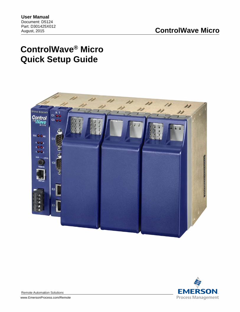
www.EmersonProcess.com/Remote Remote Automation Solutions User Manual Document: D5124 Part: D301425X012 August, 2015 ControlWave Micro ControlWave ® Micro Quick Setup Guide
Transcript of ControlWave Micro Quick Setup Guide (D301425X012) · PDF fileControlWave Micro Quick Setup...
www.EmersonProcess.com/Remote
Remote Automation Solutions
User Manual Document: D5124 Part: D301425X012 August, 2015
ControlWave Micro
ControlWave® Micro Quick Setup Guide
IMPORTANT! READ INSTRUCTIONS BEFORE STARTING!
Be sure that these instructions are carefully read and understood before any operation is attempted. Improper use of this device in some applications may result in damage or injury. The user is urged to keep this book filed in a convenient location for future reference.
These instructions may not cover all details or variations in equipment or cover every possible
situation to be met in connection with installation, operation or maintenance. Should problems arise that are not covered sufficiently in the text, the purchaser is advised to contact Emerson Process Management, Remote Automation Solutions for further information.
EQUIPMENT APPLICATION WARNING
The customer should note that a failure of this instrument or system, for whatever reason, may leave an operating process without protection. Depending upon the application, this could result in possible damage to property or injury to persons. It is suggested that the purchaser review the need for additional backup equipment or provide alternate means of protection such as alarm devices, output limiting, fail-safe valves, relief valves, emergency shutoffs, emergency switches, etc. If additional information is required, the purchaser is advised to contact Remote Automation Solutions.
RETURNED EQUIPMENT WARNING
When returning any equipment to Remote Automation Solutions for repairs or evaluation, please note the following: The party sending such materials is responsible to ensure that the materials returned to Remote Automation Solutions are clean to safe levels, as such levels are defined and/or determined by applicable federal, state and/or local law regulations or codes. Such party agrees to indemnify Remote Automation Solutions and save Remote Automation Solutions harmless from any liability or damage which Remote Automation Solutions may incur or suffer due to such party's failure to so act.
ELECTRICAL GROUNDING
Metal enclosures and exposed metal parts of electrical instruments must be grounded in accordance with OSHA rules and regulations pertaining to "Design Safety Standards for Electrical Systems," 29 CFR, Part 1910, Subpart S, dated: April 16, 1981 (OSHA rulings are in agreement with the National Electrical Code).
The grounding requirement is also applicable to mechanical or pneumatic instruments that
include electrically operated devices such as lights, switches, relays, alarms, or chart drives. EQUIPMENT DAMAGE FROM ELECTROSTATIC DISCHARGE VOLTAGE
This product contains sensitive electronic components that can be damaged by exposure to an electrostatic discharge (ESD) voltage. Depending on the magnitude and duration of the ESD, this can result in erratic operation or complete failure of the equipment. Read supplemental document S14006 for proper care and handling of ESD-sensitive components.
ControlWave Micro Quick Setup Guide
Revised Aug-2015 Before You Begin iii
Before You Begin
Thank you for choosing ControlWave Micro!
We hope you will find ControlWave Micro to be the best solution for your process automation needs.
From the start, we designed this unit to merge the simplicity and modularity of a programmable logic controller, with the full communication and programming capabilities of a remote process controller. The result - the ControlWave Micro Process Automation Controller, is a true PLC/RTU hybrid, incorporating the best features of both types of devices.
ControlWave Micro features a low-power, modular design, which supports all five IEC 61131-3 programming languages: ladder logic (LD), sequential flow chart (SFC), function block diagram (FBD), structured text (ST), and instruction list (IL). A full suite of PC-based configuration wizards and programming tools is provided.
Stay Safe!
Throughout your configuration activities, please be aware of the following items:
WARNING – SHOCK HAZARD
Always follow accepted safety guidelines. As with all electronic devices, improper installation, grounding, or usage can cause an electrical shock. If you have any doubts about how to install, ground, and use this product safely, please consult a qualified electrician.
To ensure safe use of this product, please review and follow the instructions in the following supplemental documentation:
Supplement Guide - ControlWave Site Considerations for Equipment Installation, Grounding, and Wiring (S1400CW)
ESDS Manual – Care and Handling of PC Boards and ESD Sensitive Components (S14006)
WARNING – EXPLOSION HAZARD
Because ControlWave Micro is sometimes used in Class I Division 2 hazardous locations, where there could be explosive vapors or other dangerous substances, you MUST observe and follow all regulations and warnings about proper installation, use, and repair in these environments. Failure to follow these instructions could result in an explosion, injury, or death.
Carefully review ALL warnings in the CI-ControlWave Micro hardware manual, especially those from Underwriter’s Laboratories (see Appendix A of CI-ControlWave Micro).
ControlWave Micro Quick Setup Guide
iv Before You Begin Revised Aug-2015
How to use this guide
This guide is intended to help you get “up-and-running” with a minimal amount of effort. Chapter 1 talks about setting up the hardware, and the remaining chapters talk about installing and using ControlWave Designer software, and about how to configure certain parameters.
See this: For information on:
Chapter 1 Setting up the hardware.
Chapter 2 Software installation.
Chapter 3 Creating a ControlWave project in ControlWave Designer.
Chapter 4 Setting up RTU parameters.
This guide does NOT, however, tell you everything you need to know about setting up and configuring a ControlWave Micro. We have included references throughout this book to other places in the documentation set, where you can get more details on a particular subject.
If you need help…
If you're having problems setting up and configuring your ControlWave, please call our technical support team.
The technical support phone number in the U.S. is: 1-800-537-9313; for international numbers use this link: http://www2.emersonprocess.com/en-US/brands/remote/systems_and_software/supportnet/support_contacts/Pages/support_contacts.aspx
Alternatively, log into SupportNet at this link: http://www3.emersonprocess.com/remote/support/support_login.html
ControlWave Micro Quick Setup Guide
Issued Aug-2015 Contents v
Contents
Chapter 1 – Setting up the Hardware 1-1
Chapter 2 – Installing ControlWave Designer Software on the PC 2-1 2.1 Recommended Requirements for the OpenBSI Workstation: .................................................. 2-1 2.2 Before You Begin the Software Installation .............................................................................. 2-2 2.3 Installing the ControlWave Designer Software ......................................................................... 2-2
Chapter 3 – Creating a Simple Project in Ladder Language (LD) 3-1 3.1 Connect the PC Workstation to the ControlWave Micro ........................................................... 3-1 3.2 Start ControlWave Designer: .................................................................................................... 3-1 3.3 Open a New Project .................................................................................................................. 3-2 3.4 Insert a new logical program organization unit (POU). ............................................................. 3-2 3.5 Name the POU, and specify it as a program in ladder (LD). .................................................... 3-3 3.6 Create a Contact Network ......................................................................................................... 3-3 3.7 Define the “WATER_LOW” variable. ........................................................................................ 3-5 3.8 Insert a parallel contact below, and define the “DRAIN_OPEN” variable ................................. 3-6 3.9 Define the START_PUMP variable: .......................................................................................... 3-7 3.10 Create a task, and associate the program with that task: ......................................................... 3-8 3.11 Compile the program: .............................................................................................................. 3-10 3.12 Download the project into the ControlWave Micro .................................................................. 3-11 3.13 Test the logic of the program in Debug Mode ......................................................................... 3-16
Chapter 4 – Configuring RTU Parameters 4-1 4.1 Starting the Flash Configuration Utility ...................................................................................... 4-1
4.1.1 Method 1: Starting from within LocalView ..................................................................... 4-1 4.1.2 Method 2: Starting from within NetView (ControlWave Micro Already in a Network) ... 4-3 4.1.3 Method 3: Starting from within TechView ..................................................................... 4-4
4.2 Using the Flash Configuration Utility ......................................................................................... 4-7 4.2.1 Flash Configuration Utility Buttons ................................................................................ 4-9
4.3 Setting Soft Switches .............................................................................................................. 4-14 4.3.1 Saving Changes When You Finish ............................................................................. 4-15
4.4 Setting Up a BSAP Slave Port ................................................................................................ 4-15 4.4.1 Saving Changes When You Finish ............................................................................. 4-17
4.5 Setting Up an Ethernet Port .................................................................................................... 4-17 4.5.1 Recommended Ranges for IP Addresses ................................................................... 4-19 4.5.2 Other Port Types: ........................................................................................................ 4-20 4.5.3 Saving Changes When You Finish ............................................................................. 4-20
4.6 Setting IP Parameters ............................................................................................................. 4-21 4.6.1 Saving Changes When You Finish ............................................................................. 4-22
4.7 Configuring Usernames and Passwords ................................................................................. 4-23 4.7.1 Adding a New User ..................................................................................................... 4-23 4.7.2 Modifying the Privileges of an Existing User ............................................................... 4-26 4.7.3 Deleting an Existing User ............................................................................................ 4-26 4.7.4 Saving Changes When You Finish ............................................................................. 4-26
4.8 What’s Next? ........................................................................................................................... 4-27
Appendix A – Troubleshooting Tips A-1

ControlWave Micro Quick Setup Guide
Revised Aug-2015 Setting up the Hardware 1-1
Chapter 1 – Setting up the Hardware
Note: Depending upon how you order it, your ControlWave Micro may ship from the factory already assembled, or as a separate housing and modules you must install yourself. If you order it pre-assembled, you can omit those portions of this chapter that discuss installation of individual modules.
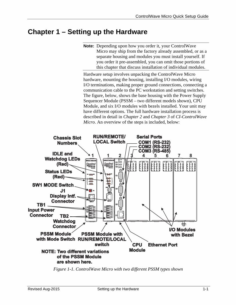
Hardware setup involves unpacking the ControlWave Micro hardware, mounting the housing, installing I/O modules, wiring I/O terminations, making proper ground connections, connecting a communication cable to the PC workstation and setting switches. The figure, below, shows the base housing with the Power Supply Sequencer Module (PSSM – two different models shown), CPU Module, and six I/O modules with bezels installed. Your unit may have different options. The full hardware installation process is described in detail in Chapter 2 and Chapter 3 of CI-ControlWave Micro. An overview of the steps is included, below:
PSSM Module withRUN/REMOTE/LOCAL
switch
PSSM Module withRUN/REMOTE/LOCAL
switch
PSSM Modulewith Mode Switch
PSSM Modulewith Mode Switch
CPUModule
CPUModule
I/O Moduleswith Bezel
I/O Moduleswith Bezel
1 2 3 4 5 6 7 81
Chassis SlotNumbers
Chassis SlotNumbers
Serial PortsSerial Ports
COM1 (RS-232)COM1 (RS-232)COM2 (RS-232)COM2 (RS-232)COM3 (RS-485)COM3 (RS-485)
Status LEDs(Red)
Status LEDs(Red)
IDLE andWatchdog LEDs
(Red)
IDLE andWatchdog LEDs
(Red)
RUN/REMOTE/LOCAL SwitchRUN/REMOTE/LOCAL Switch
SW1 MODE SwitchSW1 MODE Switch
J1Display Intf.Connector
J1Display Intf.Connector
TB1Input PowerConnector
TB1Input PowerConnector TB2
WatchdogConnector
TB2WatchdogConnector
Ethernet PortEthernet Port
3
5 6
4
21
12
1
2
1
3
{ {3
5 6
4
21
NOTE: Two different variationsof the PSSM Moduleare shown here.
NOTE: Two different variationsof the PSSM Moduleare shown here.
Figure 1-1. ControlWave Micro with two different PSSM types shown
ControlWave Micro Quick Setup Guide
1-2 Setting Up the Hardware Revised Aug-2015
1. Remove the base housing from its carton and install it at its assigned work site. (See Section 2.2 of CI-ControlWave Micro.)
2. Remove any expansion housing units from their cartons, and attach them to the base housing. (See Section 2.2 of CI-ControlWave Micro.)
3. Remove the Power Supply Sequencer Module (PSSM) from its carton. (See Section 2.3 of CI-ControlWave Micro.) Set jumpers based on your power DC power requirements (see Section 2.3.3 of CI-ControlWave Micro). Install the PSSM into base housing slot 1, that is, the first slot from the left end of the installed unit.
4. Remove the CPU module from its carton. (See Section 2.4 of CI-ControlWave Micro.) Enable the backup battery by installing backup battery board jumper JP8 onto pins 1 and 2. (See Section 2.4.1 of CI-ControlWave Micro.) Now, you must set CPU module DIP Switches.
Notes:
CPU Module DIP Switches must be configured before the CPU module has been installed into the base housing. (See Section 2.4.2 of CI-ControlWave Micro.)
For the initial configuration activities described in this manual, we recommend you leave the CPU switch settings in their default positions, as set at the factory as follows: o Switch bank SW1: all switches in the OFF position. o Switch bank SW2: all switches in the ON position, except
for SW2-4, which should be OFF.
5. Install the CPU module into base housing slot 2, which is the
second slot from the left end of the installed unit.
6. For the configuration activities, described in this manual, we will use RS-232 serial communication port 2 (Comm Port 2) on the ControlWave Micro, which is configured by default for 9600 baud. (For more information on RS-232 serial communication ports see Section 2.4.3 of CI-ControlWave Micro).
7. Plug one end of an RS-232 null modem cable into one of your PC communication ports.
Note: See Figure 2-17 in CI-ControlWave Micro for a wiring diagram of an RS-232 null modem cable.
8. Plug the other end of the RS-232 null modem cable into serial communication port 2 (Comm Port 2) of the ControlWave Micro.
ControlWave Micro Quick Setup Guide
Revised Aug-2015 Setting up the Hardware 1-3
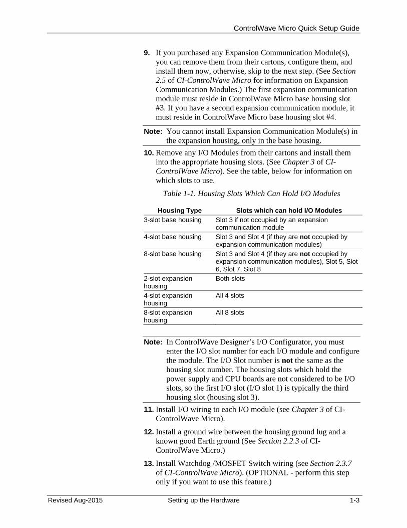
9. If you purchased any Expansion Communication Module(s), you can remove them from their cartons, configure them, and install them now, otherwise, skip to the next step. (See Section 2.5 of CI-ControlWave Micro for information on Expansion Communication Modules.) The first expansion communication module must reside in ControlWave Micro base housing slot #3. If you have a second expansion communication module, it must reside in ControlWave Micro base housing slot #4.
Note: You cannot install Expansion Communication Module(s) in the expansion housing, only in the base housing.
10. Remove any I/O Modules from their cartons and install them into the appropriate housing slots. (See Chapter 3 of CI-ControlWave Micro). See the table, below for information on which slots to use.
Table 1-1. Housing Slots Which Can Hold I/O Modules
Housing Type Slots which can hold I/O Modules 3-slot base housing Slot 3 if not occupied by an expansion
communication module
4-slot base housing Slot 3 and Slot 4 (if they are not occupied by expansion communication modules)
8-slot base housing Slot 3 and Slot 4 (if they are not occupied by expansion communication modules), Slot 5, Slot 6, Slot 7, Slot 8
2-slot expansion housing
Both slots
4-slot expansion housing
All 4 slots
8-slot expansion housing
All 8 slots
Note: In ControlWave Designer’s I/O Configurator, you must enter the I/O slot number for each I/O module and configure the module. The I/O Slot number is not the same as the housing slot number. The housing slots which hold the power supply and CPU boards are not considered to be I/O slots, so the first I/O slot (I/O slot 1) is typically the third housing slot (housing slot 3).
11. Install I/O wiring to each I/O module (see Chapter 3 of CI-ControlWave Micro).
12. Install a ground wire between the housing ground lug and a known good Earth ground (See Section 2.2.3 of CI-ControlWave Micro.)
13. Install Watchdog /MOSFET Switch wiring (see Section 2.3.7 of CI-ControlWave Micro). (OPTIONAL - perform this step only if you want to use this feature.)
ControlWave Micro Quick Setup Guide
1-4 Setting Up the Hardware Revised Aug-2015
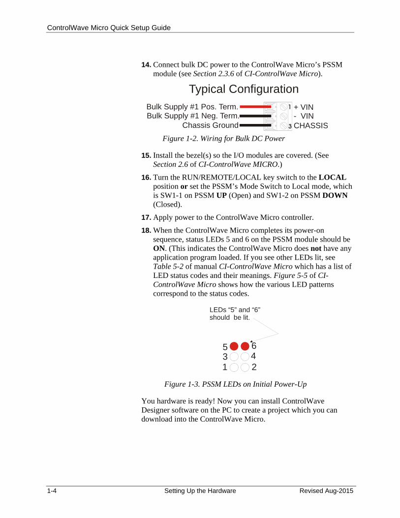
+ VIN- VINCHASSIS
Bulk Supply #1 Pos. Term.Bulk Supply #1 Neg. Term.
Chassis Ground
Typical Configuration
531
642
LEDs “5” and “6” should be lit.
14. Connect bulk DC power to the ControlWave Micro’s PSSM module (see Section 2.3.6 of CI-ControlWave Micro).
Figure 1-2. Wiring for Bulk DC Power
15. Install the bezel(s) so the I/O modules are covered. (See Section 2.6 of CI-ControlWave MICRO.)
16. Turn the RUN/REMOTE/LOCAL key switch to the LOCAL position or set the PSSM’s Mode Switch to Local mode, which is SW1-1 on PSSM UP (Open) and SW1-2 on PSSM DOWN (Closed).
17. Apply power to the ControlWave Micro controller.
18. When the ControlWave Micro completes its power-on sequence, status LEDs 5 and 6 on the PSSM module should be ON. (This indicates the ControlWave Micro does not have any application program loaded. If you see other LEDs lit, see Table 5-2 of manual CI-ControlWave Micro which has a list of LED status codes and their meanings. Figure 5-5 of CI-ControlWave Micro shows how the various LED patterns correspond to the status codes.
Figure 1-3. PSSM LEDs on Initial Power-Up
You hardware is ready! Now you can install ControlWave Designer software on the PC to create a project which you can download into the ControlWave Micro.
ControlWave Micro Quick Setup Guide
Revised Aug-2015 Installing ControlWave Designer 2-1
Chapter 2 – Installing ControlWave Designer Software on the PC
Note: This chapter outlines the basic steps in installing ControlWave Designer software. For more detailed instructions, see Chapter 2 of the OpenBSI Utilities Manual (D5081).
2.1 Recommended Requirements for the OpenBSI Workstation:
To run ControlWave Designer your PC workstation must meet the following minimum system requirements:
1 GHz processor at least 200 MB free disk space for use by OpenBSI 512 MB RAM (more recommended) CD-ROM drive VGA Monitor (minimum 256 colors 800x600). Optimal screen
resolution for OpenBSI web pages is 1024 x 768. Mouse Communication cable(s) to connect the PC to the ControlWave
Micro. Microsoft® Windows® 2003 Server, 2008 Server, XP
Professional, 7.0, or Vista. OpenBSI only supports 32-bit operating systems. We recommend you install the latest available service pack for your operating system.
Note: Emerson only tests OpenBSI and ControlWave Designer on the following platforms: Windows™ XP Professional, Windows Vista/7.0 and Windows™ 2003/2008 Server including both dual core, and dual-core dual-processor computers.
Microsoft® Internet Explorer Version 5 or newer (Required for ControlWave web pages).
Note: If you use Microsoft® Windows XP Service Pack 2 (or newer), you must change default operating system settings for certain OpenBSI features to work. Please see the Using OpenBSI with Microsoft® Windows XP Service Pack 2 notes in Chapter 2 of the OpenBSI Utilities Manual (D5081).
ControlWave Micro Quick Setup Guide
2-2 Installing ControlWave Designer Revised Aug-2015
2.2 Before You Begin the Software Installation
ControlWave Designer software is installed from within Windows. We recommend that all other Windows application programs you have running should be shut down before beginning installation.
Note: You must log in with Windows administrative privileges to install the software.
2.3 Installing the ControlWave Designer Software
1. Log into the workstation with administrative privileges.
2. Insert the OpenBSI CD-ROM in your CD-ROM drive.
3. If your CD-ROM drive has autorun enabled, skip to the next step. Otherwise, use Windows™ Explorer to locate the file BROWSER.EXE in the root directory of the CD. Double-click on BROWSER.EXE. When the CD browser screen appears, choose the Install OpenBSI option.
4. A screen reminds you to close all other programs, and warns you that older OpenBSI versions will be removed. Click Next.
5. A license agreement screen opens. Review the agreement, using the scroll bar to bring it into view. Click I accept the terms of the license agreement to proceed. Then click Next.
6. Now you must choose the installation directory on your computer for OpenBSI.. The default directory is \Program Files\Bristol\OpenBSI. Either accept the default or click Browse to specify a new directory. Then click Next.
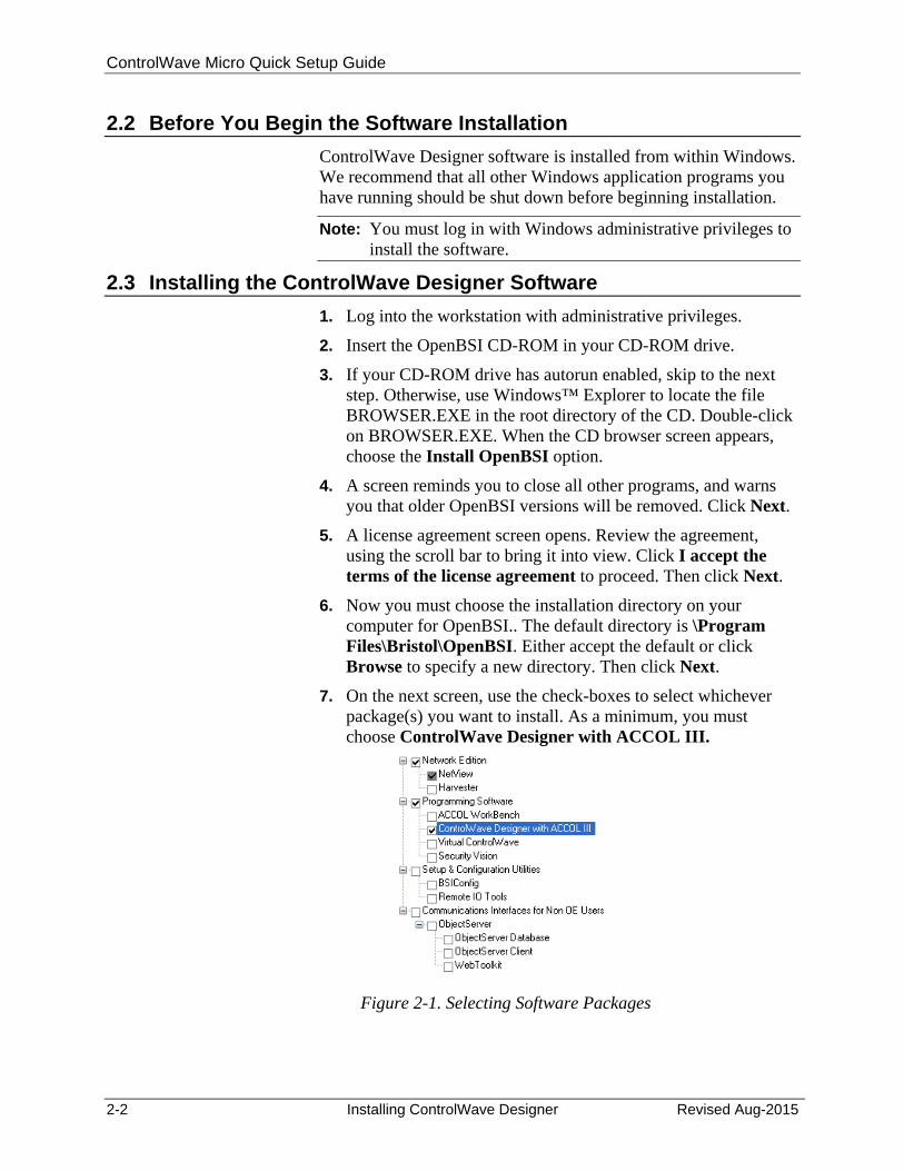
7. On the next screen, use the check-boxes to select whichever package(s) you want to install. As a minimum, you must choose ControlWave Designer with ACCOL III.
Figure 2-1. Selecting Software Packages
ControlWave Micro Quick Setup Guide
Revised Aug-2015 Installing ControlWave Designer 2-3
8. Once you make your choices, click Next.
9. On the next screen you can specify the user files folder. The system stores user files such as ControlWave projects, recipes, and network files in sub-folders of this folder. Note: If User Account Control (UAC) is enabled in Windows, you must have write access to this folder. The default is C:\OpenBSI. Use the default or use Browse to specify a different user files folder. When finished click Next.
10. This is your last opportunity to make any changes prior to starting the installation. If you want to make changes, you can click Back to go back to earlier pages. If you want to read the printed release notes for this version of OpenBSI, check the View the Release Notes box.
11. If you are ready to perform the installation, click Install, and the installation process starts. Be patient, as it may take several minutes to install all of the different utilities, depending upon which you choose.
12. When the installation completes, re-boot your computer when prompted. This must be done in order for OpenBSI to function properly. If you choose not to re-boot now, you must do so before running OpenBSI. Click Finish, and the installation will be complete, and re-boot will proceed, if you chose to do it now.
After re-boot, an “OpenBSI Tools” menu selection is added to your Windows Start Programs menu through which you can access the various OpenBSI utilities. If you prefer, you can create Windows shortcuts to the tools to provide access through icons on the desktop. See your Windows documentation for information on how to do this.
a Simple Project in Ladder Language (LD)

ControlWave Micro Quick Setup Guide
Revised: Aug-2015 Creating a Simple Project 3-1
Chapter 3 – Creating a Simple Project in Ladder Language (LD)
Now, let's create a very simple project to run in your ControlWave Micro. Let's say we have a water tank - when the water level in the tank goes below a certain level, a WATER_LOW signal is turned ON, and as a result, a START_PUMP signal needs to be turned ON to refill the tank. Similarly, we want to issue a START_PUMP signal any time the drain valve for the tank is open. Our project is so simple, we aren't going to handle turning off the pump, or what happens if the tank overflows; we just want to show how either of two conditions cause the pump to be started.
Note: We won't be defining the I/O for this project; we're keeping it as simple as possible.
3.1 Connect the PC Workstation to the ControlWave Micro
1. Plug one end of a null modem cable into your PC serial port.
2. Plug the other end of the cable into one of the RS-232 serial communication ports on the ControlWave Micro.
Note: Later in this chapter, you’ll need to know the baud rate of the ControlWave Micro serial port. See Table 4-1 in CI-ControlWave Micro for details on factory default baud rates for the ControlWave Micro serial ports.
3.2 Start ControlWave Designer:
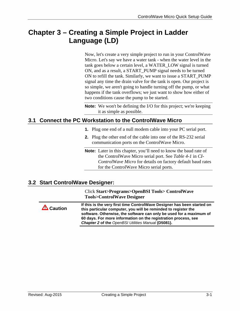
Click Start>Programs>OpenBSI Tools> ControlWave Tools>ControlWave Designer
Caution If this is the very first time ControlWave Designer has been started on this particular computer, you will be reminded to register the software. Otherwise, the software can only be used for a maximum of 60 days. For more information on the registration process, see Chapter 2 of the OpenBSI Utilities Manual (D5081).
ControlWave Micro Quick Setup Guide
3-2 Creating a Simple Project Revised: Aug-2015
3.3 Open a New Project
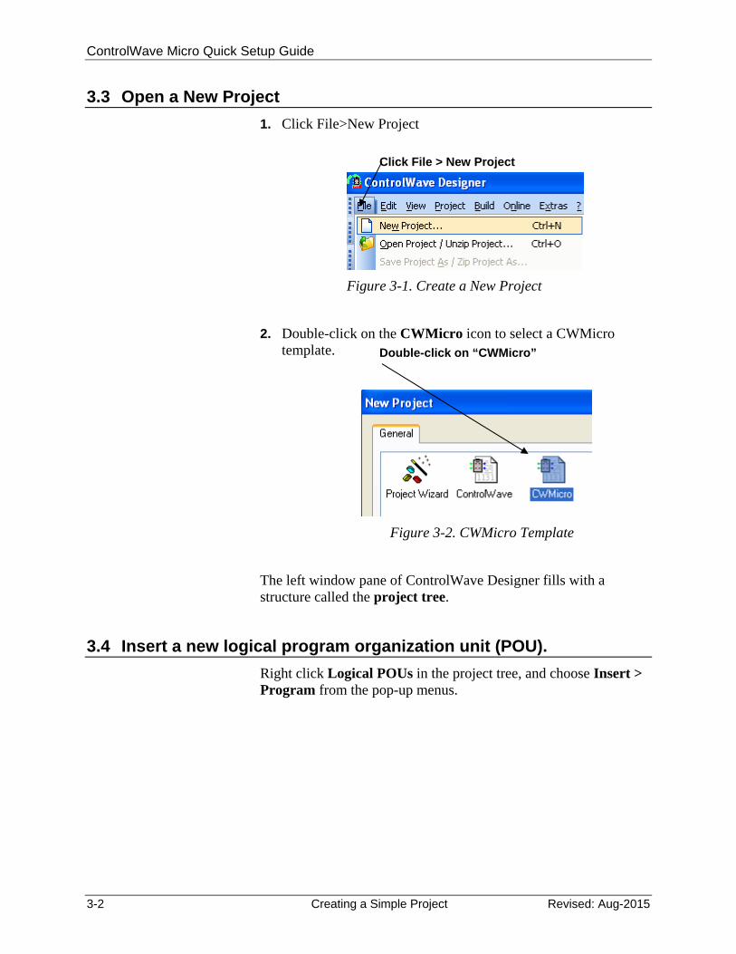
1. Click File>New Project
Figure 3-1. Create a New Project
2. Double-click on the CWMicro icon to select a CWMicro
template.
Figure 3-2. CWMicro Template
The left window pane of ControlWave Designer fills with a structure called the project tree.
3.4 Insert a new logical program organization unit (POU).
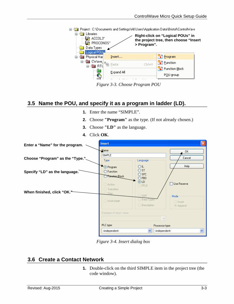
Right click Logical POUs in the project tree, and choose Insert > Program from the pop-up menus.
Click File > New Project
Double-click on “CWMicro”
ControlWave Micro Quick Setup Guide
Revised: Aug-2015 Creating a Simple Project 3-3
Figure 3-3. Choose Program POU
3.5 Name the POU, and specify it as a program in ladder (LD).
1. Enter the name “SIMPLE”.
2. Choose "Program" as the type. (If not already chosen.)
3. Choose "LD" as the language.
4. Click OK.
Figure 3-4. Insert dialog box
3.6 Create a Contact Network
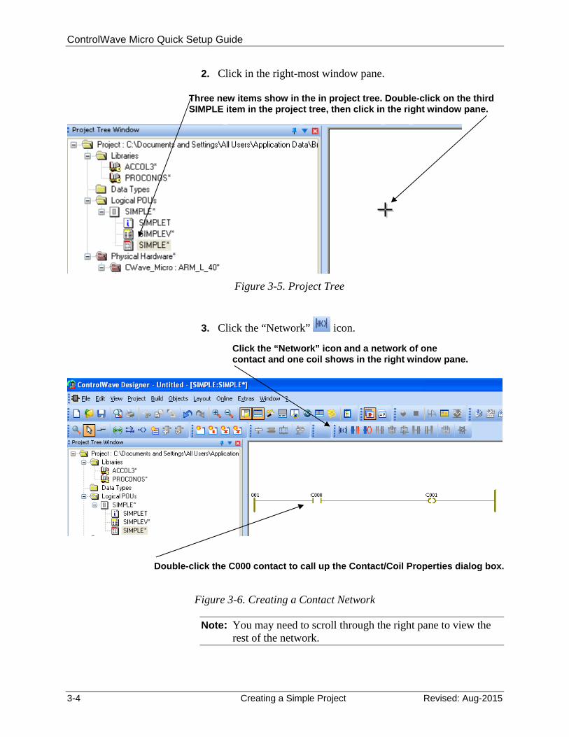
1. Double-click on the third SIMPLE item in the project tree (the code window).
Right-click on “Logical POUs” in the project tree, then choose “Insert > Program”.
Enter a “Name” for the program.
Choose “Program” as the “Type.”
Specify “LD” as the language.
When finished, click “OK.”
ControlWave Micro Quick Setup Guide
3-4 Creating a Simple Project Revised: Aug-2015
2. Click in the right-most window pane.
Figure 3-5. Project Tree
3. Click the “Network” icon.
Figure 3-6. Creating a Contact Network
Note: You may need to scroll through the right pane to view the rest of the network.
Three new items show in the in project tree. Double-click on the third SIMPLE item in the project tree, then click in the right window pane.
Click the “Network” icon and a network of one contact and one coil shows in the right window pane.
Double-click the C000 contact to call up the Contact/Coil Properties dialog box.
ControlWave Micro Quick Setup Guide
Revised: Aug-2015 Creating a Simple Project 3-5
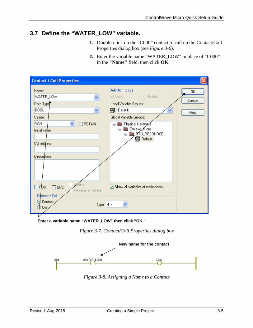
3.7 Define the “WATER_LOW” variable.
1. Double-click on the “C000” contact to call up the Contact/Coil Properties dialog box (see Figure 3-6).
2. Enter the variable name “WATER_LOW” in place of “C000” in the "Name" field, then click OK.
Figure 3-7. Contact/Coil Properties dialog box
Figure 3-8. Assigning a Name to a Contact
Enter a variable name “WATER_LOW” then click “OK.”
New name for the contact
ControlWave Micro Quick Setup Guide
3-6 Creating a Simple Project Revised: Aug-2015
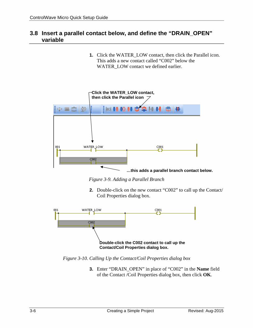
3.8 Insert a parallel contact below, and define the “DRAIN_OPEN” variable
1. Click the WATER_LOW contact, then click the Parallel icon.
This adds a new contact called “C002” below the WATER_LOW contact we defined earlier.
Figure 3-9. Adding a Parallel Branch
2. Double-click on the new contact “C002” to call up the Contact/ Coil Properties dialog box.
Figure 3-10. Calling Up the Contact/Coil Properties dialog box
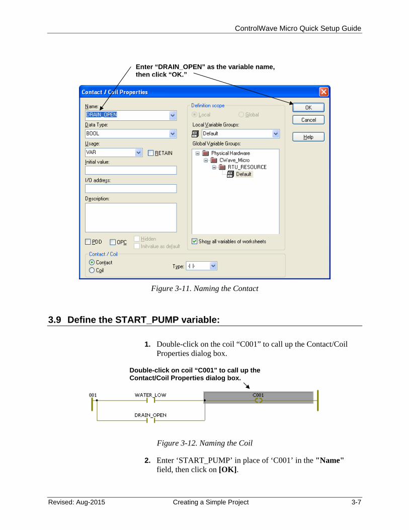
3. Enter “DRAIN_OPEN” in place of “C002” in the Name field of the Contact /Coil Properties dialog box, then click OK.
Click the WATER_LOW contact, then click the Parallel icon
…this adds a parallel branch contact below.
Double-click the C002 contact to call up the Contact/Coil Properties dialog box.
ControlWave Micro Quick Setup Guide
Revised: Aug-2015 Creating a Simple Project 3-7
Figure 3-11. Naming the Contact
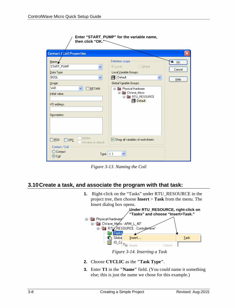
3.9 Define the START_PUMP variable:
1. Double-click on the coil “C001” to call up the Contact/Coil
Properties dialog box.
Figure 3-12. Naming the Coil
2. Enter ‘START_PUMP’ in place of ‘C001’ in the "Name" field, then click on [OK].
Enter “DRAIN_OPEN” as the variable name, then click “OK.”
Double-click on coil “C001” to call up the Contact/Coil Properties dialog box.
ControlWave Micro Quick Setup Guide
3-8 Creating a Simple Project Revised: Aug-2015
Figure 3-13. Naming the Coil
3.10 Create a task, and associate the program with that task:
1. Right-click on the “Tasks” under RTU_RESOURCE in the project tree, then choose Insert > Task from the menu. The Insert dialog box opens.
Figure 3-14. Inserting a Task
2. Choose CYCLIC as the "Task Type".
3. Enter T1 in the "Name" field. (You could name it something else; this is just the name we chose for this example.)
Enter “START_PUMP” for the variable name, then click “OK.”
Under RTU_RESOURCE, right-click on “Tasks” and choose “Insert>Task.”
ControlWave Micro Quick Setup Guide
Revised: Aug-2015 Creating a Simple Project 3-9
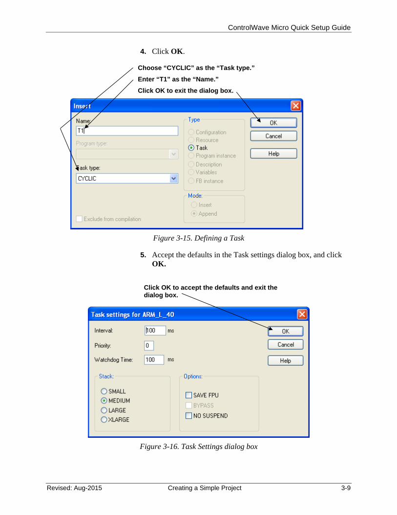
4. Click OK.
Figure 3-15. Defining a Task
5. Accept the defaults in the Task settings dialog box, and click OK.
Figure 3-16. Task Settings dialog box
Choose “CYCLIC” as the “Task type.”
Enter “T1” as the “Name.”
Click OK to exit the dialog box.
Click OK to accept the defaults and exit the dialog box.
ControlWave Micro Quick Setup Guide
3-10 Creating a Simple Project Revised: Aug-2015
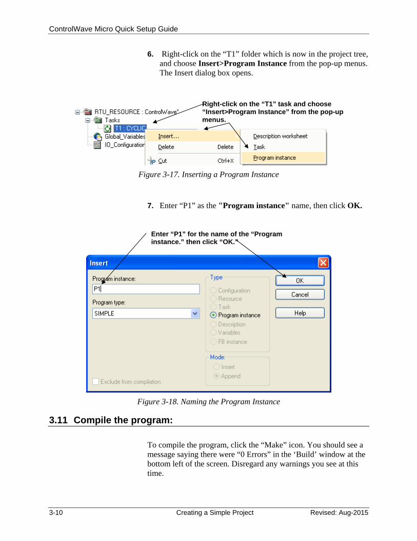
6. Right-click on the “T1” folder which is now in the project tree, and choose Insert>Program Instance from the pop-up menus. The Insert dialog box opens.
Figure 3-17. Inserting a Program Instance
7. Enter “P1” as the "Program instance" name, then click OK.
Figure 3-18. Naming the Program Instance
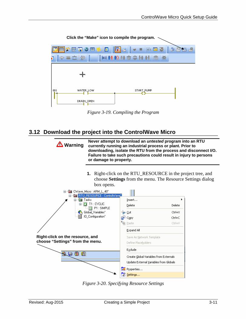
3.11 Compile the program:
To compile the program, click the “Make” icon. You should see a message saying there were “0 Errors” in the ‘Build’ window at the bottom left of the screen. Disregard any warnings you see at this time.
Right-click on the “T1” task and choose “Insert>Program Instance” from the pop-up menus.
Enter “P1” for the name of the “Program instance,” then click “OK.”
ControlWave Micro Quick Setup Guide
Revised: Aug-2015 Creating a Simple Project 3-11
Figure 3-19. Compiling the Program
3.12 Download the project into the ControlWave Micro
Warning Never attempt to download an untested program into an RTU currently running an industrial process or plant. Prior to downloading, isolate the RTU from the process and disconnect I/O. Failure to take such precautions could result in injury to persons or damage to property.
1. Right-click on the RTU_RESOURCE in the project tree, and
choose Settings from the menu. The Resource Settings dialog box opens.
Figure 3-20. Specifying Resource Settings
Click the “Make” icon to compile the program.
Right-click on the resource, and choose “Settings” from the menu.
ControlWave Micro Quick Setup Guide
3-12 Creating a Simple Project Revised: Aug-2015
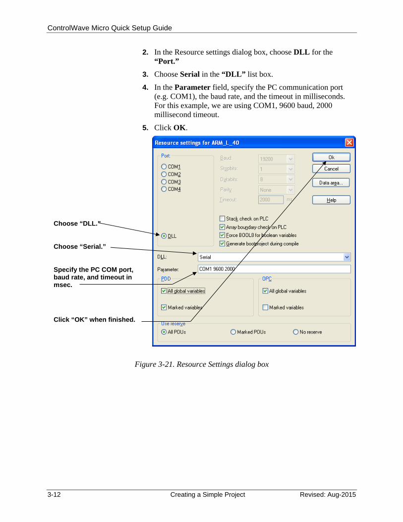
2. In the Resource settings dialog box, choose DLL for the “Port.”
3. Choose Serial in the “DLL” list box.
4. In the Parameter field, specify the PC communication port (e.g. COM1), the baud rate, and the timeout in milliseconds. For this example, we are using COM1, 9600 baud, 2000 millisecond timeout.
5. Click OK.
Figure 3-21. Resource Settings dialog box
Choose “DLL.”
Choose “Serial.”
Specify the PC COM port, baud rate, and timeout in msec.
Click “OK” when finished.
ControlWave Micro Quick Setup Guide
Revised: Aug-2015 Creating a Simple Project 3-13
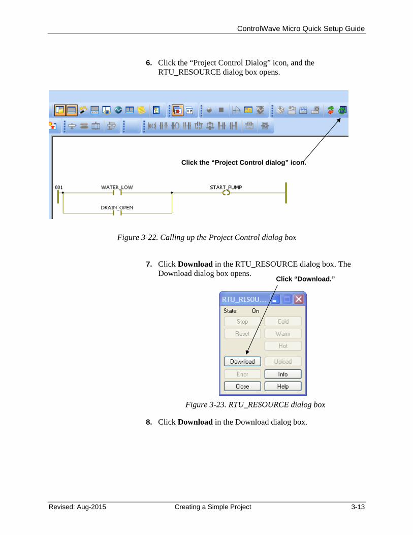
6. Click the “Project Control Dialog” icon, and the
RTU_RESOURCE dialog box opens.
Figure 3-22. Calling up the Project Control dialog box
7. Click Download in the RTU_RESOURCE dialog box. The
Download dialog box opens.
Figure 3-23. RTU_RESOURCE dialog box
8. Click Download in the Download dialog box.
Click the “Project Control dialog” icon.
Click “Download.”
ControlWave Micro Quick Setup Guide
3-14 Creating a Simple Project Revised: Aug-2015
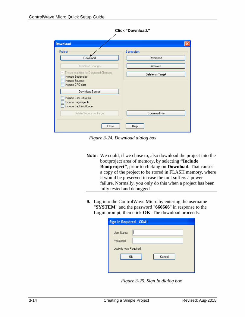
Figure 3-24. Download dialog box
Note: We could, if we chose to, also download the project into the bootproject area of memory, by selecting “Include Bootproject”, prior to clicking on Download. That causes a copy of the project to be stored in FLASH memory, where it would be preserved in case the unit suffers a power failure. Normally, you only do this when a project has been fully tested and debugged.
9. Log into the ControlWave Micro by entering the username
"SYSTEM" and the password "666666" in response to the Login prompt, then click OK. The download proceeds.
Figure 3-25. Sign In dialog box
Click “Download.”
ControlWave Micro Quick Setup Guide
Revised: Aug-2015 Creating a Simple Project 3-15
531
642
LED “6” should be lit, indicatingthat an application(project) is loaded.
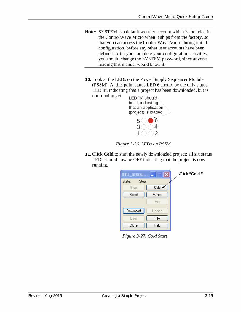
Note: SYSTEM is a default security account which is included in the ControlWave Micro when it ships from the factory, so that you can access the ControlWave Micro during initial configuration, before any other user accounts have been defined. After you complete your configuration activities, you should change the SYSTEM password, since anyone reading this manual would know it.
10. Look at the LEDs on the Power Supply Sequencer Module (PSSM). At this point status LED 6 should be the only status LED lit, indicating that a project has been downloaded, but is not running yet.
Figure 3-26. LEDs on PSSM
11. Click Cold to start the newly downloaded project; all six status LEDs should now be OFF indicating that the project is now running.
Figure 3-27. Cold Start
Click “Cold.”
ControlWave Micro Quick Setup Guide
3-16 Creating a Simple Project Revised: Aug-2015
3.13 Test the logic of the program in Debug Mode
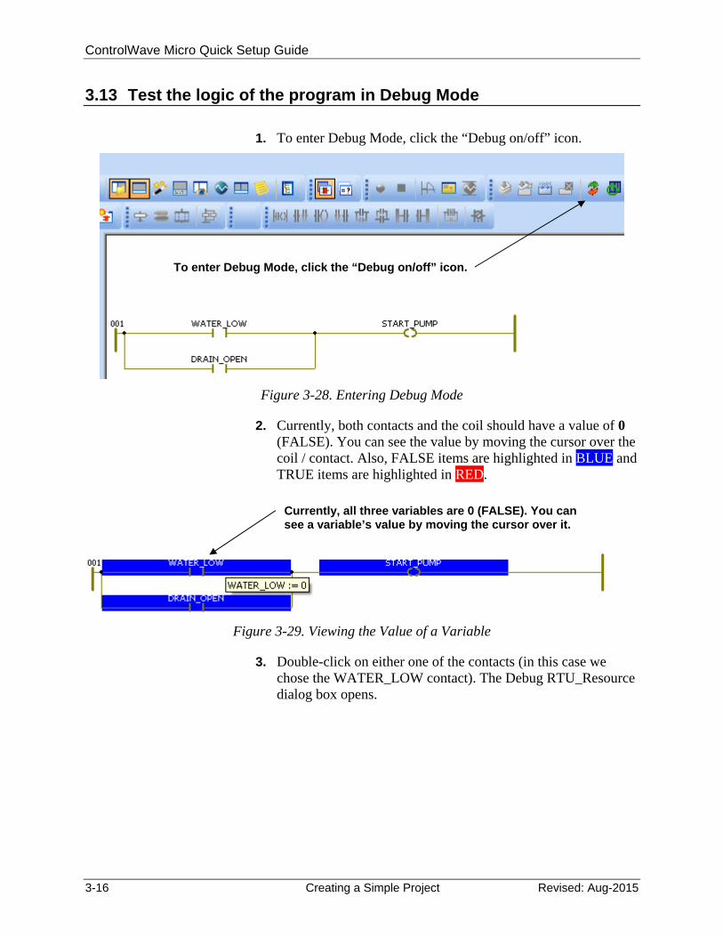
1. To enter Debug Mode, click the “Debug on/off” icon.
Figure 3-28. Entering Debug Mode
2. Currently, both contacts and the coil should have a value of 0 (FALSE). You can see the value by moving the cursor over the coil / contact. Also, FALSE items are highlighted in BLUE and TRUE items are highlighted in RED.
Figure 3-29. Viewing the Value of a Variable
3. Double-click on either one of the contacts (in this case we chose the WATER_LOW contact). The Debug RTU_Resource dialog box opens.
To enter Debug Mode, click the “Debug on/off” icon.
Currently, all three variables are 0 (FALSE). You can see a variable’s value by moving the cursor over it.
ControlWave Micro Quick Setup Guide
Revised: Aug-2015 Creating a Simple Project 3-17
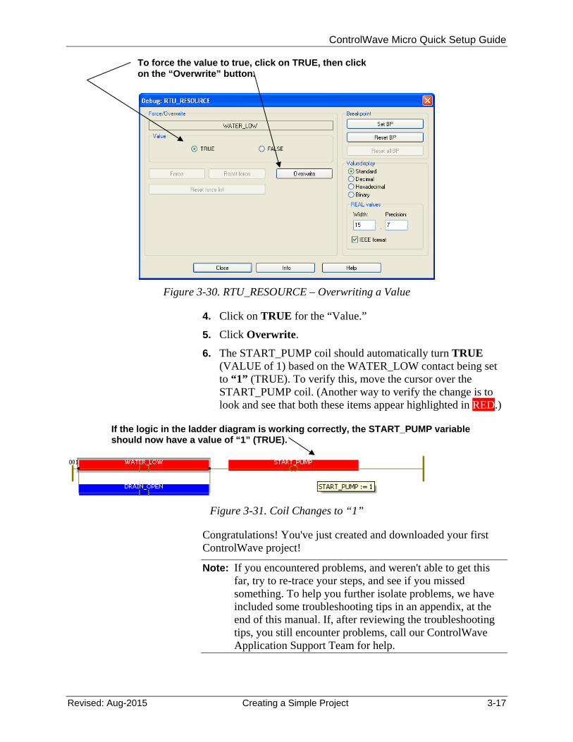
Figure 3-30. RTU_RESOURCE – Overwriting a Value
4. Click on TRUE for the “Value.”
5. Click Overwrite.
6. The START_PUMP coil should automatically turn TRUE (VALUE of 1) based on the WATER_LOW contact being set to “1” (TRUE). To verify this, move the cursor over the START_PUMP coil. (Another way to verify the change is to look and see that both these items appear highlighted in RED.)
Figure 3-31. Coil Changes to “1”
Congratulations! You've just created and downloaded your first ControlWave project!
Note: If you encountered problems, and weren't able to get this far, try to re-trace your steps, and see if you missed something. To help you further isolate problems, we have included some troubleshooting tips in an appendix, at the end of this manual. If, after reviewing the troubleshooting tips, you still encounter problems, call our ControlWave Application Support Team for help.
To force the value to true, click on TRUE, then click on the “Overwrite” button.
If the logic in the ladder diagram is working correctly, the START_PUMP variable should now have a value of “1” (TRUE).

ControlWave Micro Quick Setup Guide
Revised: Aug-2015 Configuring RTU Parameters 4-1
Chapter 4 – Configuring RTU Parameters
Note: This chapter assumes you already have a communication cable connected between the OpenBSI workstation and the ControlWave Micro.
Now that you've created a project, and downloaded it successfully, it's time to learn more about configuring the ControlWave Micro. The configuration in this part is performed using the Flash Configuration Utility.
We’re going to talk about using the Flash Configuration Utility to set your ControlWave Micro’s soft switches, configure its communication ports, set IP parameters, and configure security accounts for its users.
4.1 Starting the Flash Configuration Utility
The way you start the Flash Configuration Utility varies depending upon whether you use LocalView, NetView, or TechView to communicate with the ControlWave Micro.
4.1.1 Method 1: Starting from within LocalView
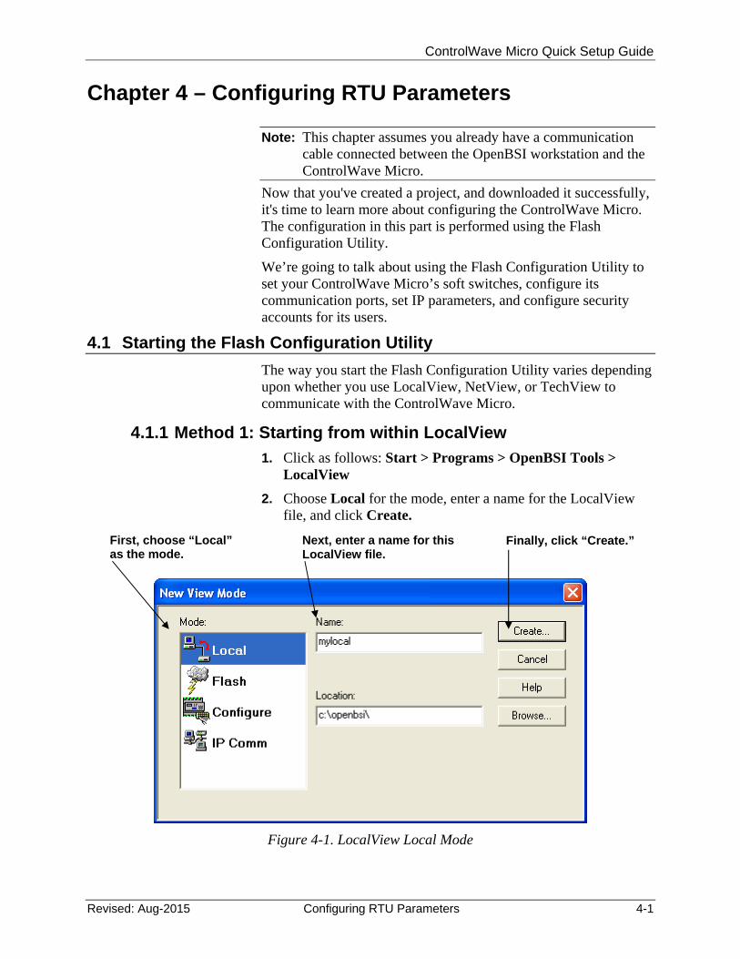
1. Click as follows: Start > Programs > OpenBSI Tools > LocalView
2. Choose Local for the mode, enter a name for the LocalView file, and click Create.
Figure 4-1. LocalView Local Mode
First, choose “Local” as the mode.
Next, enter a name for this LocalView file.
Finally, click “Create.”
ControlWave Micro Quick Setup Guide
4-2 Configuring RTU Parameters Revised: Aug-2015
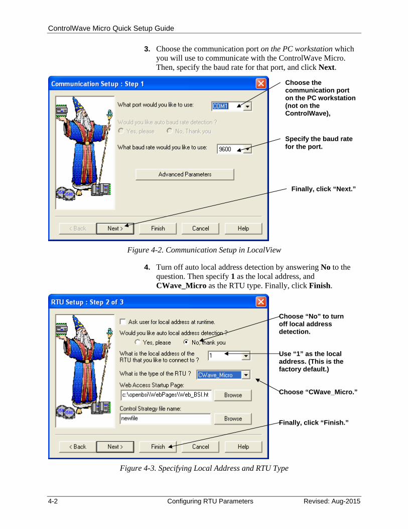
3. Choose the communication port on the PC workstation which you will use to communicate with the ControlWave Micro. Then, specify the baud rate for that port, and click Next.
Figure 4-2. Communication Setup in LocalView
4. Turn off auto local address detection by answering No to the question. Then specify 1 as the local address, and CWave_Micro as the RTU type. Finally, click Finish.
Figure 4-3. Specifying Local Address and RTU Type
Choose the communication port on the PC workstation (not on the ControlWave),
Specify the baud rate for the port.
Finally, click “Next.”
Choose “No” to turn off local address detection.
Choose “CWave_Micro.”
Finally, click “Finish.”
Use “1” as the local address. (This is the factory default.)
ControlWave Micro Quick Setup Guide
Revised: Aug-2015 Configuring RTU Parameters 4-3
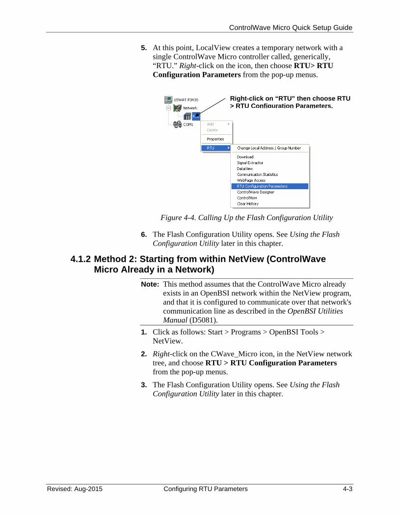
5. At this point, LocalView creates a temporary network with a single ControlWave Micro controller called, generically, “RTU.” Right-click on the icon, then choose RTU> RTU Configuration Parameters from the pop-up menus.
Figure 4-4. Calling Up the Flash Configuration Utility
6. The Flash Configuration Utility opens. See Using the Flash Configuration Utility later in this chapter.
4.1.2 Method 2: Starting from within NetView (ControlWave Micro Already in a Network)
Note: This method assumes that the ControlWave Micro already exists in an OpenBSI network within the NetView program, and that it is configured to communicate over that network's communication line as described in the OpenBSI Utilities Manual (D5081).
1. Click as follows: Start > Programs > OpenBSI Tools > NetView.
2. Right-click on the CWave_Micro icon, in the NetView network tree, and choose RTU > RTU Configuration Parameters from the pop-up menus.
3. The Flash Configuration Utility opens. See Using the Flash Configuration Utility later in this chapter.
Right-click on “RTU” then choose RTU > RTU Configuration Parameters.
ControlWave Micro Quick Setup Guide
4-4 Configuring RTU Parameters Revised: Aug-2015
Figure 4-5. Calling Up the Flash Configuration Utility
4.1.3 Method 3: Starting from within TechView
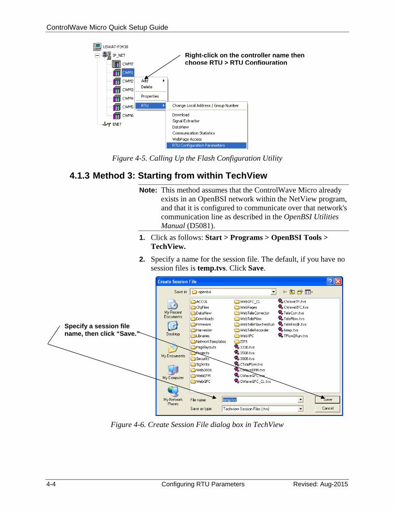
Note: This method assumes that the ControlWave Micro already exists in an OpenBSI network within the NetView program, and that it is configured to communicate over that network's communication line as described in the OpenBSI Utilities Manual (D5081).
1. Click as follows: Start > Programs > OpenBSI Tools > TechView.
2. Specify a name for the session file. The default, if you have no session files is temp.tvs. Click Save.
Figure 4-6. Create Session File dialog box in TechView
Right-click on the controller name then choose RTU > RTU Configuration
Specify a session file name, then click “Save.”
ControlWave Micro Quick Setup Guide
Revised: Aug-2015 Configuring RTU Parameters 4-5
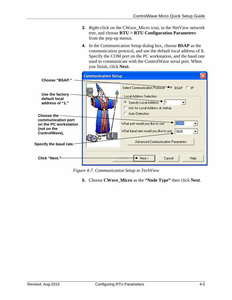
3. Right-click on the CWave_Micro icon, in the NetView network tree, and choose RTU > RTU Configuration Parameters from the pop-up menus.
4. In the Communication Setup dialog box, choose BSAP as the communication protocol, and use the default local address of 1. Specify the COM port on the PC workstation, and the baud rate used to communicate with the ControlWave serial port. When you finish, click Next.
Figure 4-7. Communication Setup in TechView
5. Choose CWave_Micro as the “Node Type” then click Next.
Use the factory default local address of “1.”
Choose “BSAP.”
Specify the baud rate.
Click “Next.”
Choose the communication port on the PC workstation (not on the ControlWave),

ControlWave Micro Quick Setup Guide
4-6 Configuring RTU Parameters Revised: Aug-2015
Figure 4-8. TechView Node Setup dialog box
6. In the Calibration Setup dialog box, specify “1” for the number of transmitters (TechView assumes you have at least one transmitter). Then click Finish.
Figure 4-9. Calling Up the Flash Configuration Utility
7. Now log into the ControlWave Micro with your Username and Password.
Choose CWave_Micro.
Click “Next.”
Click “Finish.”
First specify “1” for the number of transmitters.
ControlWave Micro Quick Setup Guide
Revised: Aug-2015 Configuring RTU Parameters 4-7
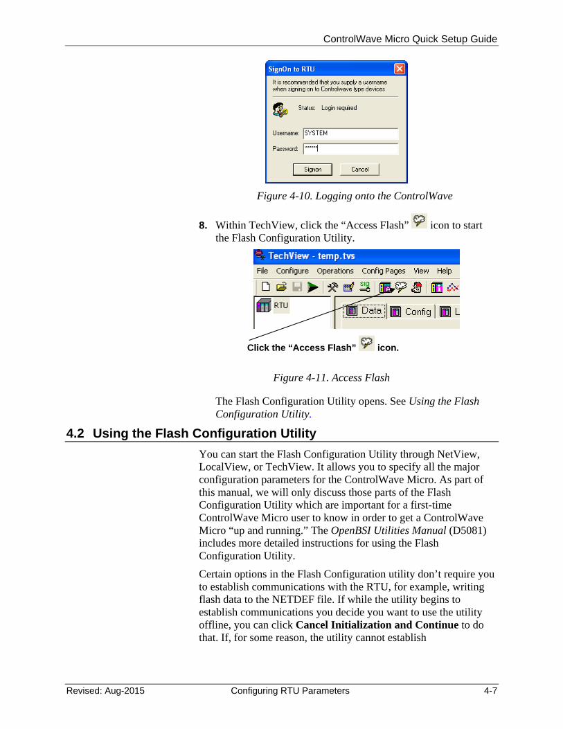
Figure 4-10. Logging onto the ControlWave
8. Within TechView, click the “Access Flash” icon to start the Flash Configuration Utility.
Figure 4-11. Access Flash
9. The Flash Configuration Utility opens. See Using the Flash Configuration Utility.ng the Flash Configuration Utility
4.2 Using the Flash Configuration Utility
You can start the Flash Configuration Utility through NetView, LocalView, or TechView. It allows you to specify all the major configuration parameters for the ControlWave Micro. As part of this manual, we will only discuss those parts of the Flash Configuration Utility which are important for a first-time ControlWave Micro user to know in order to get a ControlWave Micro “up and running.” The OpenBSI Utilities Manual (D5081) includes more detailed instructions for using the Flash Configuration Utility.
Certain options in the Flash Configuration utility don’t require you to establish communications with the RTU, for example, writing flash data to the NETDEF file. If while the utility begins to establish communications you decide you want to use the utility offline, you can click Cancel Initialization and Continue to do that. If, for some reason, the utility cannot establish
Click the “Access Flash” icon.
ControlWave Micro Quick Setup Guide
4-8 Configuring RTU Parameters Revised: Aug-2015
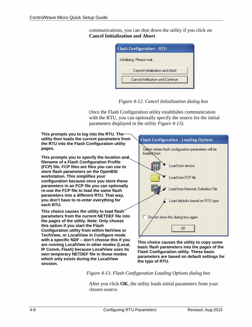
communications, you can shut down the utility if you click on Cancel Initialization and Abort.
Figure 4-12. Cancel Initialization dialog box
Once the Flash Configuration utility establishes communication with the RTU, you can optionally specify the source for the initial parameters displayed in the utility Figure 4-13).
Figure 4-13. Flash Configuration Loading Options dialog box
After you click OK, the utility loads initial parameters from your chosen source.
This prompts you to log into the RTU. The utility then loads the current parameters from the RTU into the Flash Configuration utility pages.
This prompts you to specify the location and filename of a Flash Configuration Profile (FCP) file. FCP files are files you can use to store flash parameters on the OpenBSI workstation. This simplifies your configuration because once you store these parameters in an FCP file you can optionally re-use the FCP file to load the same flash parameters into a different RTU. That way, you don’t have to re-enter everything for each RTU.
This choice causes the utility to copy some basic flash parameters into the pages of the Flash Configuration utility. These basic parameters are based on default settings for the type of RTU.
This choice causes the utility to load flash parameters from the current NETDEF file into the pages of the utility. Note: Only choose this option if you start the Flash Configuration utility from within NetView or TechView, or LocalView in Configure mode with a specific NDF – don’t choose this if you are running LocalView in other modes (Local, IP Comm, Flash) because LocalView uses its own temporary NETDEF file in those modes which only exists during the LocalView session.
ControlWave Micro Quick Setup Guide
Revised: Aug-2015 Configuring RTU Parameters 4-9
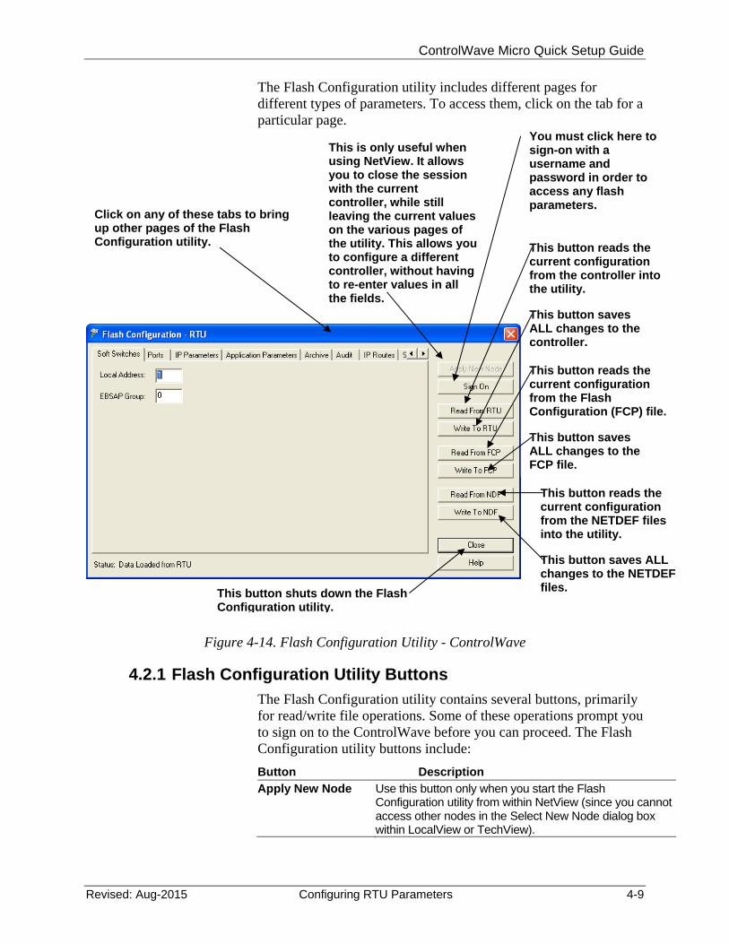
The Flash Configuration utility includes different pages for different types of parameters. To access them, click on the tab for a particular page.
Figure 4-14. Flash Configuration Utility - ControlWave
4.2.1 Flash Configuration Utility Buttons
The Flash Configuration utility contains several buttons, primarily for read/write file operations. Some of these operations prompt you to sign on to the ControlWave before you can proceed. The Flash Configuration utility buttons include:
Button Description
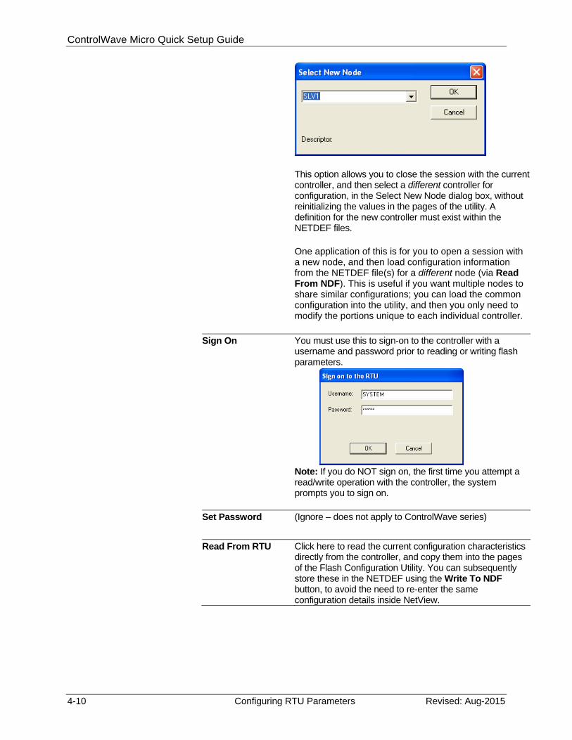
Apply New Node Use this button only when you start the Flash Configuration utility from within NetView (since you cannot access other nodes in the Select New Node dialog box within LocalView or TechView).
Click on any of these tabs to bring up other pages of the Flash Configuration utility.
This is only useful when using NetView. It allows you to close the session with the current controller, while still leaving the current values on the various pages of the utility. This allows you to configure a different controller, without having to re-enter values in all the fields.
You must click here to sign-on with a username and password in order to access any flash parameters.
This button reads the current configuration from the NETDEF files into the utility.
This button saves ALL changes to the NETDEF files.
This button reads the current configuration from the controller into the utility.
This button saves ALL changes to the controller.
This button reads the current configuration from the Flash Configuration (FCP) file.
This button saves ALL changes to the FCP file.
This button shuts down the Flash Configuration utility.
ControlWave Micro Quick Setup Guide
4-10 Configuring RTU Parameters Revised: Aug-2015
This option allows you to close the session with the current controller, and then select a different controller for configuration, in the Select New Node dialog box, without reinitializing the values in the pages of the utility. A definition for the new controller must exist within the NETDEF files. One application of this is for you to open a session with a new node, and then load configuration information from the NETDEF file(s) for a different node (via Read From NDF). This is useful if you want multiple nodes to share similar configurations; you can load the common configuration into the utility, and then you only need to modify the portions unique to each individual controller.
Sign On You must use this to sign-on to the controller with a username and password prior to reading or writing flash parameters.
Note: If you do NOT sign on, the first time you attempt a read/write operation with the controller, the system prompts you to sign on.
Set Password (Ignore – does not apply to ControlWave series)
Read From RTU
Click here to read the current configuration characteristics directly from the controller, and copy them into the pages of the Flash Configuration Utility. You can subsequently store these in the NETDEF using the Write To NDF button, to avoid the need to re-enter the same configuration details inside NetView.
ControlWave Micro Quick Setup Guide
Revised: Aug-2015 Configuring RTU Parameters 4-11
Note: LocalView prompts you to sign on when you click this button, if you did not sign on previously.
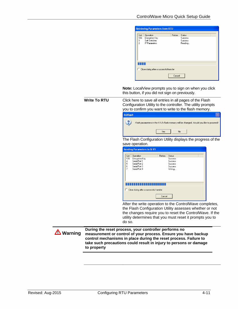
Write To RTU Click here to save all entries in all pages of the Flash Configuration Utility to the controller. The utility prompts you to confirm you want to write to the flash memory.
The Flash Configuration Utility displays the progress of the save operation.
After the write operation to the ControlWave completes, the Flash Configuration Utility assesses whether or not the changes require you to reset the ControlWave. If the utility determines that you must reset it prompts you to do so.
Warning During the reset process, your controller performs no measurement or control of your process. Ensure you have backup control mechanisms in place during the reset process. Failure to take such precautions could result in injury to persons or damage to property
ControlWave Micro Quick Setup Guide
4-12 Configuring RTU Parameters Revised: Aug-2015
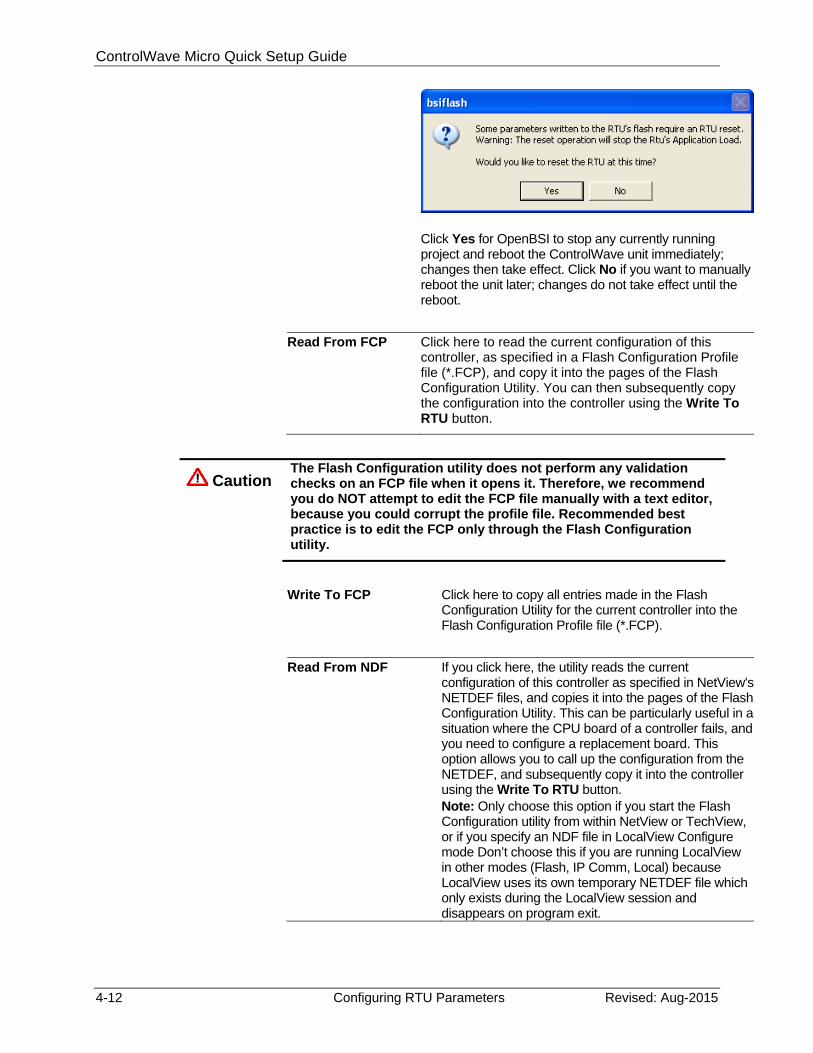
Click Yes for OpenBSI to stop any currently running project and reboot the ControlWave unit immediately; changes then take effect. Click No if you want to manually reboot the unit later; changes do not take effect until the reboot.
Read From FCP Click here to read the current configuration of this controller, as specified in a Flash Configuration Profile file (*.FCP), and copy it into the pages of the Flash Configuration Utility. You can then subsequently copy the configuration into the controller using the Write To RTU button.
Caution The Flash Configuration utility does not perform any validation checks on an FCP file when it opens it. Therefore, we recommend you do NOT attempt to edit the FCP file manually with a text editor, because you could corrupt the profile file. Recommended best practice is to edit the FCP only through the Flash Configuration utility.
Write To FCP Click here to copy all entries made in the Flash
Configuration Utility for the current controller into the Flash Configuration Profile file (*.FCP).
Read From NDF If you click here, the utility reads the current configuration of this controller as specified in NetView's NETDEF files, and copies it into the pages of the Flash Configuration Utility. This can be particularly useful in a situation where the CPU board of a controller fails, and you need to configure a replacement board. This option allows you to call up the configuration from the NETDEF, and subsequently copy it into the controller using the Write To RTU button. Note: Only choose this option if you start the Flash Configuration utility from within NetView or TechView, or if you specify an NDF file in LocalView Configure mode Don’t choose this if you are running LocalView in other modes (Flash, IP Comm, Local) because LocalView uses its own temporary NETDEF file which only exists during the LocalView session and disappears on program exit.
ControlWave Micro Quick Setup Guide
Revised: Aug-2015 Configuring RTU Parameters 4-13
Write To NDF If you click here, the utility copies all entries you made in the Flash Configuration Utility for the current controller into the current NETDEF file. This avoids the need to re-enter the same configuration information in NetView. Note: Only choose this option if you start the Flash Configuration utility from within NetView or TechView, or if you specify an NDF file in LocalView Configure mode. Don’t choose this if you are running LocalView in other modes (Flash, IP Comm, Local) because LocalView uses its own temporary NETDEF file which only exists during the LocalView session and disappears on program exit.
Close Click here to shut down the Flash Configuration Utility.
The various configuration settings are separated into different pages of the utility. You can access them by clicking on the tab for a particular page. The different pages include:
Soft Switches - the most important of these is the BSAP local address of the controller.
Ports - this includes all communication ports on the ControlWave Micro - up to eleven serial ports (COM1 through COM11), and one or two Ethernet IP ports. Note:: The number of ports varies depending upon the type of CPU module you purchased and whether or not you purchased expansion communication modules for your ControlWave Micro.
IP Parameters - if this controller performs IP communications, certain parameters such as the IP address of the Network Host PC (NHP), UDP socket numbers, and the address of the default gateway must be configured. Some of the parameters on this page are outside the scope of this manual.
Application Parameters - Most of these are “tuning” parameters which govern how the ControlWave Micro executes its application (project). A discussion of application parameters is outside the scope of this manual.
Archive - Archive data is one portion of the historical capabilities of the ControlWave MICRO controller. It allows ‘snapshots’ of many variables to be saved at the same instant, to provide a detailed historical record of process variables at a particular moment in time. The archive data is saved at the controller, in structures called archive files and is configured, in part, using the ARCHIVE function block in your ControlWave project. Archive files may be collected by OpenBSI Utilities such as DataView, or the Harvester. A discussion of archive configuration is outside the scope of this manual.
ControlWave Micro Quick Setup Guide
4-14 Configuring RTU Parameters Revised: Aug-2015
Audit - Audit data is one portion of the historical capabilities of the ControlWave MICRO controller. It allows records to be kept of when certain variables change value, as well as recording all alarms in the system. The Audit page specifies various parameters used to set up the Audit system. Configuration is also performed, in part, using the AUDIT function block in your ControlWave project. A discussion of audit configuration is outside the scope of this manual.
IP Routes - Dynamic IP routes allow messages which cannot successfully reach a particular destination address, to be re-routed through a different path in the IP network. A discussion of this subject is outside the scope of this manual.
Security - This page allows configuration of user accounts and privileges.
4.3 Setting Soft Switches
The ControlWave Micro controller, unlike earlier Network 3000 controller models, does not have physical DIP switches for setting the BSAP local address or EBSAP group number. Instead, you configure these from the Soft Switches tab of the Flash Configuration Utility.
Field Description
Local Address The default "Local Address" for a ControlWave Micro, when it ships from the factory, is 1. Local addresses are integer values from 1 to 127, and OpenBSI uses them to identify the location of a controller in a network. The local address of a particular controller must be unique within the network. The local address you enter here must match the local address you define in NetView.
Note: If you change the local address, be sure to make note of the new address because you will need to know it to communicate with this ControlWave in subsequent communication sessions, and if you want to include this ControlWave in a BSAP network. If you’re just setting up a single ControlWave Micro to experiment with, you should leave the local address at the default of 1.
EBSAP Group Leave the "EBSAP Group" number at 0, unless your network is configured for Expanded Node Addressing (EBSAP). EBSAP adds a level of complexity to network configuration, and is only necessary in very large networks where more than 127 slave controllers are defined underneath a given master controller, and for whatever reason, BSAP communication is required, instead of IP communication. For more information about Expanded Node Addressing, see the ControlWave Designer Programmer’s Handbook (D5125).
ControlWave Micro Quick Setup Guide
Revised: Aug-2015 Configuring RTU Parameters 4-15
Figure 4-15. Soft Switches tab
4.3.1 Saving Changes When You Finish
Click Write To RTU, and the utility sends the new configuration parameter values to FLASH memory in the ControlWave Micro. Depending upon which parameters you change, you may need to reset the unit for the changes to take effect.
4.4 Setting Up a BSAP Slave Port
You can configure any of the ControlWave Micro’s serial COM ports as a BSAP Slave port. BSAP stands for Bristol Synchronous / Asynchronous Protocol. It is a protocol used for communication by ControlWave and Network 3000 controllers.
You can use a BSAP Slave Port to:
communicate with OpenBSI software on the PC (such as. NetView, LocalView, DataView, and other programs)
communicate with ControlWave Designer software on the PC communicate with another controller on a higher level of the
BSAP network, which has a BSAP Master Port that addresses this controller
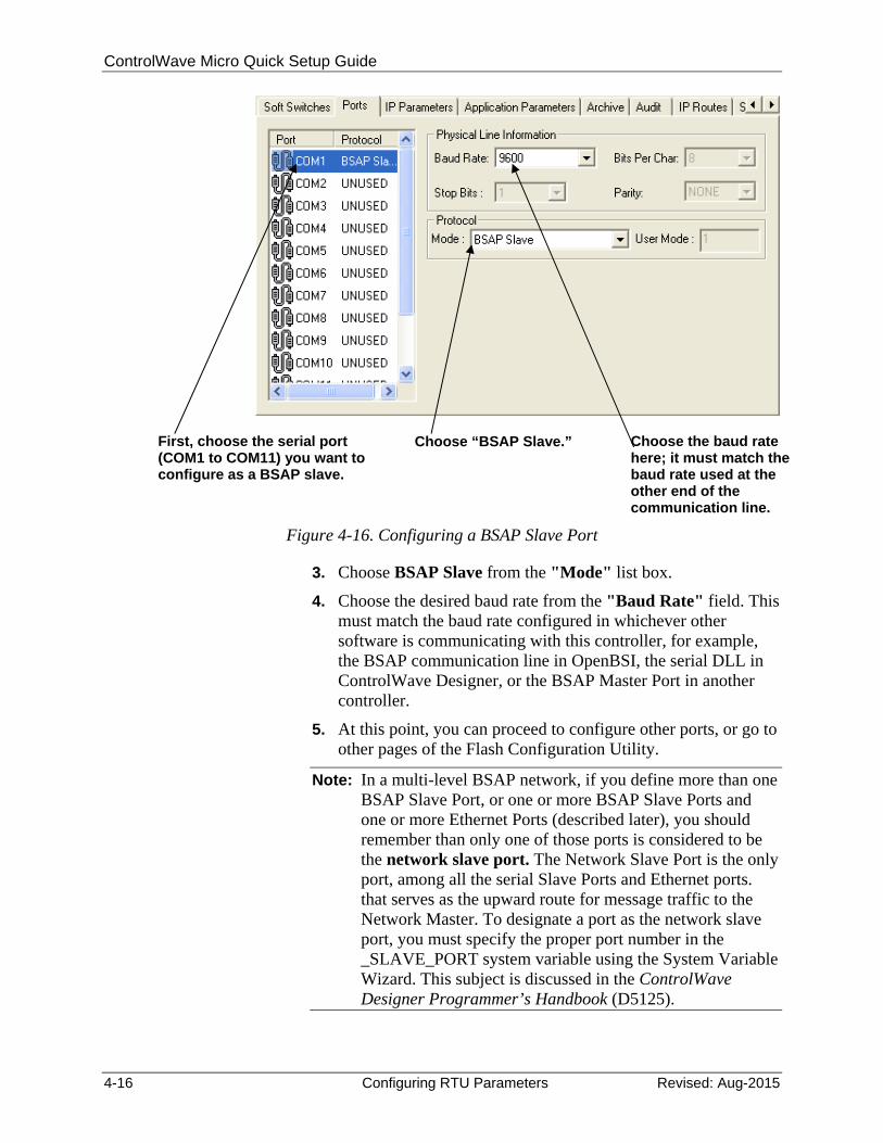
To configure the BSAP slave port, follow these steps. 1. Click the Ports tab, if you haven't already.
2. Click the icon for the ControlWave Micro port you want to configure as a BSAP Slave Port. Depending upon how many serial ports your ControlWave Micro has, a valid choice could range from COM1 through COM11.
You can specify the BSAP local address here. It must range from 1 to 127. The factory default is “1.”
If you’re not using EBSAP, you must leave this at “0.”
ControlWave Micro Quick Setup Guide
4-16 Configuring RTU Parameters Revised: Aug-2015
Figure 4-16. Configuring a BSAP Slave Port
3. Choose BSAP Slave from the "Mode" list box.
4. Choose the desired baud rate from the "Baud Rate" field. This must match the baud rate configured in whichever other software is communicating with this controller, for example, the BSAP communication line in OpenBSI, the serial DLL in ControlWave Designer, or the BSAP Master Port in another controller.
5. At this point, you can proceed to configure other ports, or go to other pages of the Flash Configuration Utility.
Note: In a multi-level BSAP network, if you define more than one BSAP Slave Port, or one or more BSAP Slave Ports and one or more Ethernet Ports (described later), you should remember than only one of those ports is considered to be the network slave port. The Network Slave Port is the only port, among all the serial Slave Ports and Ethernet ports. that serves as the upward route for message traffic to the Network Master. To designate a port as the network slave port, you must specify the proper port number in the _SLAVE_PORT system variable using the System Variable Wizard. This subject is discussed in the ControlWave Designer Programmer’s Handbook (D5125).
First, choose the serial port (COM1 to COM11) you want to configure as a BSAP slave.
Choose “BSAP Slave.” Choose the baud rate here; it must match the baud rate used at the other end of the communication line.
ControlWave Micro Quick Setup Guide
Revised: Aug-2015 Configuring RTU Parameters 4-17
4.4.1 Saving Changes When You Finish
Click Write To RTU, and the utility sends the new configuration parameter values to FLASH memory in the ControlWave Micro. Depending upon which parameters you change, you may need to reset the unit for the changes to take effect.
4.5 Setting Up an Ethernet Port
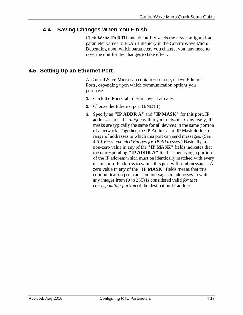
A ControlWave Micro can contain zero, one, or two Ethernet Ports, depending upon which communication options you purchase.
1. Click the Ports tab, if you haven't already.
2. Choose the Ethernet port (ENET1).
3. Specify an "IP ADDR A" and "IP MASK" for this port. IP addresses must be unique within your network. Conversely, IP masks are typically the same for all devices in the same portion of a network. Together, the IP Address and IP Mask define a range of addresses to which this port can send messages. (See 4.5.1 Recommended Ranges for IP Addresses.) Basically, a non-zero value in any of the "IP MASK" fields indicates that the corresponding "IP ADDR A" field is specifying a portion of the IP address which must be identically matched with every destination IP address to which this port will send messages. A zero value in any of the "IP MASK" fields means that this communication port can send messages to addresses in which any integer from (0 to 255) is considered valid for that corresponding portion of the destination IP address.
ControlWave Micro Quick Setup Guide
4-18 Configuring RTU Parameters Revised: Aug-2015
Figure 4-17. Setting the IP Address and Mask for the Ethernet Port
In Figure 4-17, the "IP ADDR A" for the port is 10.23.19.1 and the "IP MASK" is 255.255.0.0. This means that this port can send to any address in the format 10.23.y.z where y and z are any integer from 0 to 255. So, 10.23.127.76 and 10.23.35.93 would be valid destinations, but 24.1.1.1 would not because the 255 in the "IP MASK" indicates that the corresponding portion of the "IP ADDR A" MUST be 10.
Notes:
Leave the IP ADDR B field blank. It is reserved for redundant operations which we will not discuss in this manual.
There are other restrictions, for example, the non-zero mask entries must be all be in contiguous fields, and must begin in the left-most portion of the address. More details on these subjects are included in the OpenBSI Utilities Manual (D5081).
In newer ControlWave units, all Ethernet ports are pre-programmed at the factory with an initial IP address and mask. The optional Ethernet ports on the ControlWave Micro would default to the addresses shown below:
Port: Default IP Address: Default IP Mask: ETH1 10.0.1.1 255.255.255.0
ETH2 10.0.2.1 255.255.255.0
Scroll down and select the ENET1 port.
Specify the IP address and the IP mask.
ControlWave Micro Quick Setup Guide
Revised: Aug-2015 Configuring RTU Parameters 4-19
Because each unit shipping from the factory will have these addressesinitially pre-programmed, you should only use these addresses for “bench” testing and configuration. Each address must be changed before putting the ControlWave unit on an actual network, since an address conflict would exist as soon as the second ControlWave unit was placed online.
4. At this point, you can proceed to configure other ports, or go to
other pages of the Flash Configuration Utility.
4.5.1 Recommended Ranges for IP Addresses
If you are intend to connect your controller network directly to the global world-wide Internet, you must obtain a range of IP addresses from your Internet service provider (ISP) or from an Internet governing body such as the Internet Assigned Numbers Authority (IANA).
If you have no plans to connect your network to the global Internet, there is no restriction on your choice of IP addresses, however, the Internet Engineering Task Force recommends that IP addresses for private networks should be assigned from the following ranges:
10.0.0.0 to 10.255.255.255 172.16.0.0 to 172.31.255.255 192.168.0.0 to 192.168.255.255
Note: For information on the Internet Engineering Task Force recommendation see Rekhter, et al, Best Current Practice memo - "Address Allocation for Private Internets", Internet Engineering Task Force, RFC 1918, February, 1996. The full text of this memo is available at http://www.ietf.org.
These particular ranges of Internet addresses are reserved for private networks. Most Internet Service Providers (ISP) recognize any messages coming from these addresses as coming from private networks, and filter these messages out. This helps avoid addressing conflicts should an accidental connection occur between a private network, and the global Internet.
Devices (e.g. controllers, workstations) in our controller networks always use fixed IP addresses. This causes certain complexities if you choose to use Dynamic Host Configuration Protocol (DHCP) in your network. Because DHCP assigns IP addresses dynamically, as they are needed, you must examine your DHCP server to determine the addresses which have been assigned for each controller or workstation, and then manually enter those addresses in NetView. You should then specify the longest possible lease
ControlWave Micro Quick Setup Guide
4-20 Configuring RTU Parameters Revised: Aug-2015
time for the addresses, to help prevent the loss of a given address through a device failure.
It is also strongly recommended that you configure the DHCP server so that the addresses reserved for the controllers are permanently reserved (by tying them to the RTU MAC addresses within the DHCP configuration or by having them in a totally different address range). You should do the same when you configure RAS servers or other machines capable of providing dynamic addressing information. Otherwise, you could accidentally have duplicate IP addresses on your network.
4.5.2 Other Port Types:
There are several other possible port types which can be configured: “PPP,” “BSAP Master,” and others. These subjects are beyond the scope of this manual. See the online help in ControlWave Designer as well as Chapter 5 of the OpenBSI Utilities Manual (D5081) for more information.
4.5.3 Saving Changes When You Finish
Click Write To RTU, and the utility sends the new configuration parameter values to FLASH memory in the ControlWave Micro. Depending upon which parameters you change, you may need to reset the unit for the changes to take effect.
ControlWave Micro Quick Setup Guide
Revised: Aug-2015 Configuring RTU Parameters 4-21
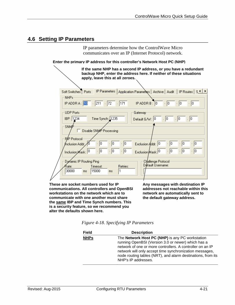
Configuring IP Parameters
4.6 Setting IP Parameters
IP parameters determine how the ControlWave Micro communicates over an IP (Internet Protocol) network.
Figure 4-18. Specifying IP Parameters
Field Description
NHPs The Network Host PC (NHP) is any PC workstation running OpenBSI (Version 3.0 or newer) which has a network of one or more controllers. A controller on an IP network will only accept time synchronization messages, node routing tables (NRT), and alarm destinations, from its NHP's IP addresses.
Enter the primary IP address for this controller’s Network Host PC (NHP)
If the same NHP has a second IP address, or you have a redundant backup NHP, enter the address here. If neither of these situations apply, leave this at all zeroes.
These are socket numbers used for IP communications. All controllers and OpenBSI workstations on the network which are to communicate with one another must share the same IBP and Time Synch numbers. This is a security feature, so we recommend you alter the defaults shown here.
Any messages with destination IP addresses not reachable within this network are automatically sent to the default gateway address.

ControlWave Micro Quick Setup Guide
4-22 Configuring RTU Parameters Revised: Aug-2015
IP ADDR A This is the primary IP address of the Network Host PC (NHP) which has the network which includes this controller.
IP ADDR B If the NHP identified above (in IP ADDR A) has a second IP address, that address may be entered here, in case the primary connection is broken. Alternatively, if there is a redundant backup NHP, its address should be entered here. If neither of these cases apply, "IP ADDR B" should be left at all zeroes.
UDP Ports UDP ports (sometimes referred to as sockets) have nothing to do with physical communication port hardware. They actually refer to entry points within the UDP communication protocol software (which is an industry standard Internet Protocol). The underlying details of UDP are beyond the scope of this document, but the parameters are included here as a security feature.
IBP IBP is the UDP port used by the IP driver software. Every OpenBSI Workstation and controller in a given network, which need to communicate via IP, MUST share the same IBP UDP socket number. For security purposes, we recommend you change the IBP port number to something other than the default value shown. This is particularly important if your network has a connection to the world-wide Internet.
Time Synch This is the UDP port used to send time synchronization messages to controllers. Every OpenBSI Workstation and controller in a given network, which needs to communicate via IP, must share the same time synch UDP socket number. For security purposes, it is recommended that you change the IBP port number to something other than the default value shown. This is particularly important if your network has a connection to the world-wide Internet.
Gateway Default G/W
If this controller receives any messages for which it cannot locate a direct route to a destination address, it sends them to the default gateway's IP address, as specified in this field. A default gateway is a device (PC workstation, remote process controller, router) which receives these messages, and attempts to route them to their destination.
SNMP, RIP Protocol, Dynamic IP Routing Ping, Challenge Protocol:
These IP parameters are used in more complicated network configurations, and to meet certain special IP security requirements. Explanations are beyond the scope of this document.
4.6.1 Saving Changes When You Finish
Click Write To RTU, and the utility sends the new configuration parameter values to FLASH memory in the ControlWave Micro.
ControlWave Micro Quick Setup Guide
Revised: Aug-2015 Configuring RTU Parameters 4-23
Depending upon which parameters you change, you may need to reset the unit for the changes to take effect.
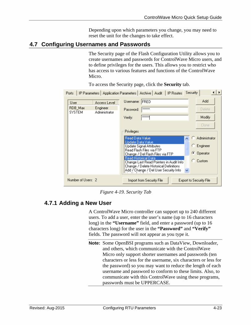
4.7 Configuring Usernames and Passwords
The Security page of the Flash Configuration Utility allows you to create usernames and passwords for ControlWave Micro users, and to define privileges for the users. This allows you to restrict who has access to various features and functions of the ControlWave Micro.
To access the Security page, click the Security tab.
Figure 4-19. Security Tab
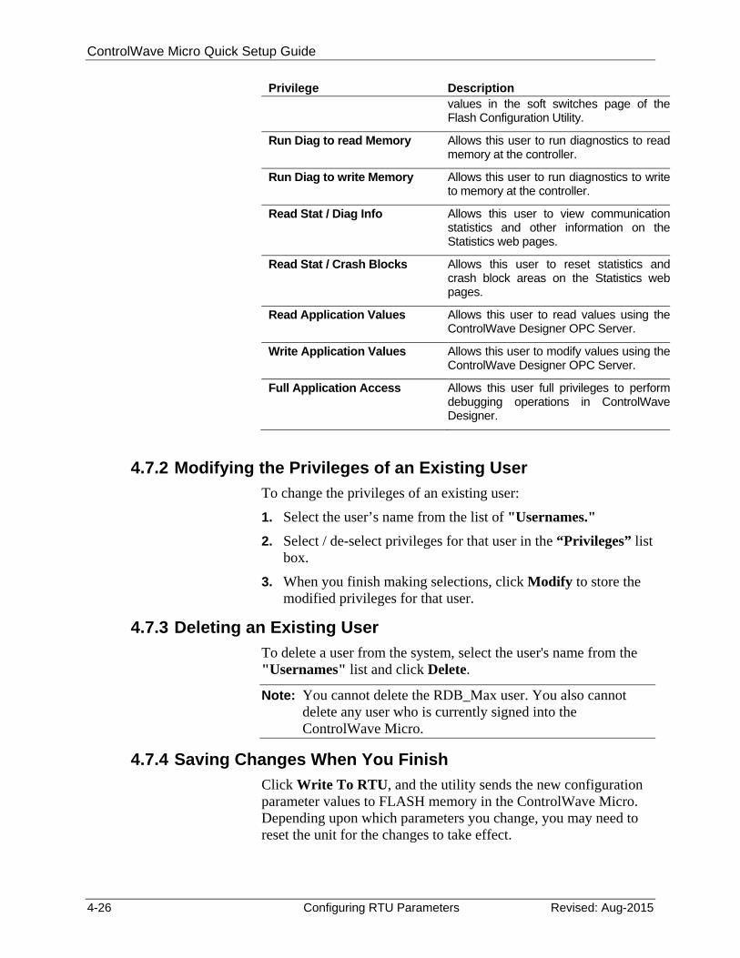
4.7.1 Adding a New User
A ControlWave Micro controller can support up to 240 different users. To add a user, enter the user’s name (up to 16 characters long) in the “Username” field, and enter a password (up to 16 characters long) for the user in the “Password” and “Verify” fields. The password will not appear as you type it.
Note: Some OpenBSI programs such as DataView, Downloader, and others, which communicate with the ControlWave Micro only support shorter usernames and passwords (ten characters or less for the username, six characters or less for the password) so you may want to reduce the length of each username and password to conform to these limits. Also, to communicate with this ControlWave using these programs, passwords must be UPPERCASE.
ControlWave Micro Quick Setup Guide
4-24 Configuring RTU Parameters Revised: Aug-2015
Next, select the privileges for this user by clicking “Custom” and then select the individual privileges in the “Privileges” list box, so they are highlighted. Alternatively, you can choose "Operator," "Engineer" or "Administrator" for a particular user, which automatically highlights privileges associated with those user categories. The tables, on the next page, show the privileges associated with these user categories, and list what all the various privileges mean.
When you have selected all desired privileges, click the Add button to add the user to the system.
Note: Every ControlWave Micro has a special user called RDB_Max. This user account defines the maximum privileges allowed for RDB protocol messages coming into the ControlWave Micro. (Programs such as DataView, the Harvester, and others use RDB messages to communicate.) You cannot delete the RDB_Max user, or rename it, but you can change its privileges.
The table below shows the privileges associated with the Operator, Engineer, and Administrator categories:
The table, below, shows the privileges associated with the Operator, Engineer, and Administrator categories:
Table 5-2. Standard User Privileges
Privilege Operator Engineer Administrator
Read Data Value
Update Data Value
Read Flash Files via FTP
Change/Del Flash Files via FTP
Read Historical Data
Change Last Read Pointers in Audit Info
Change/Delete Historical Definitions
Add / Change / Del User Security Info
Modify Soft Switches
Run Diag to read Memory
Run Diag to write Memory
ControlWave Micro Quick Setup Guide
Revised: Aug-2015 Configuring RTU Parameters 4-25
Privilege Operator Engineer Administrator
Read Stat / Diag Info
Read Stat / Crash Blocks
Read Application Values
Write Application Values
Full Application Access
Add New Historical Definitions
The table, below, describes the meaning of each privilege:
Table 5-3. User Privileges
Privilege Description
Read Data Value Allows this user to read data values fromthis controller.
Update Data Value Alows this user to change data values inthis controller.
Read Flash Files via FTP Allows this user read access (using FileTransfer Protocol) to files stored in thisControlWave's flash memory. Thisincludes the ControlWave boot project,source files (*.ZWT), etc.
Change/Del Flash Files via FTP
Allows this user (using File TransferProtocol) to change or delete files stored inthe ControlWave's flash memory. Thiscould include the ControlWave bootproject, source files (*.ZWT), etc.
Read Historical Data Allows this user to view historical data(Audit / Archive information) from thecontroller, using either web pages, orDataView.
Change Last Read Pointers in Audit Info
Allows this user to delete audit recordsfrom the controller.
Add New Historical Definitions Allows this user to create new archive filedefinitions, and / or to set up the alarm andevent buffers for audit configuration usingthe Flash Configuration Utility.
Change/Delete Historical Definitions
Allows this user to change or deletehistorical definitions via the FlashConfiguration Utility.
Add / Change / Del User Security Info
Allows this user to add, change, or deletesecurity configuration information via theFlash Configuration Utility security page.
Modify Soft Switches Allows this user to change soft switch
ControlWave Micro Quick Setup Guide
4-26 Configuring RTU Parameters Revised: Aug-2015
Privilege Description values in the soft switches page of theFlash Configuration Utility.
Run Diag to read Memory Allows this user to run diagnostics to readmemory at the controller.
Run Diag to write Memory Allows this user to run diagnostics to writeto memory at the controller.
Read Stat / Diag Info Allows this user to view communicationstatistics and other information on theStatistics web pages.
Read Stat / Crash Blocks Allows this user to reset statistics andcrash block areas on the Statistics webpages.
Read Application Values Allows this user to read values using theControlWave Designer OPC Server.
Write Application Values Allows this user to modify values using theControlWave Designer OPC Server.
Full Application Access Allows this user full privileges to performdebugging operations in ControlWaveDesigner.
4.7.2 Modifying the Privileges of an Existing User
To change the privileges of an existing user:
1. Select the user’s name from the list of "Usernames."
2. Select / de-select privileges for that user in the “Privileges” list box.
3. When you finish making selections, click Modify to store the modified privileges for that user.
4.7.3 Deleting an Existing User
To delete a user from the system, select the user's name from the "Usernames" list and click Delete.
Note: You cannot delete the RDB_Max user. You also cannot delete any user who is currently signed into the ControlWave Micro.
4.7.4 Saving Changes When You Finish
Click Write To RTU, and the utility sends the new configuration parameter values to FLASH memory in the ControlWave Micro. Depending upon which parameters you change, you may need to reset the unit for the changes to take effect.
ControlWave Micro Quick Setup Guide
Revised: Aug-2015 Configuring RTU Parameters 4-27
Unlike many of the other pages in the Flash Configuration Utility, once you click Write To RTU the changes take effect immediately.
Note: When you have finished configuring all of your user accounts, you should make sure the default switch (SW2-3) is turned ON; otherwise the special default security account (SYSTEM) remains active.
What's Next?
4.8 What’s Next?
Now that you have completed your initial configuration, you can begin developing a real ControlWave project for your particular industrial automation/control application, configure historical data parameters, etc. The table, below, lists other places in the documentation set where you can find more information:
For more information on: Please refer to:
Installation of other kits, such as OpenBSI Network Edition, OpenBSI Harvester
Chapter 2 of the OpenBSI Utilities Manual (D5081)
Creating a project in ControlWave. Example in the Getting Started with ControlWave Designer Manual (D5085)
ControlWave Designer, IEC 61131 terminology
Online help in ControlWave Designer
ACCOL3 Function Blocks Online help in ControlWave Designer
I/O Configurator Getting Started with ControlWave Designer Manual (D5085) and the ControlWave Designer Programmer’s Handbook (D5125)
OpenBSI OpenBSI Utilities Manual (D5081)
Flash Configuration Utility Chapter 5 of the OpenBSI Utilities Manual (D5081)
Historical System (audit/archive) ControlWave Designer Programmer’s Handbook (D125)
Web page controls Web_BSI Manual (D5087)
ControlWave Micro hardware CI-ControlWave Micro

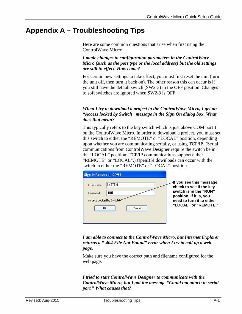
ControlWave Micro Quick Setup Guide
Revised: Aug-2015 Troubleshooting Tips A-1
Appendix A – Troubleshooting Tips
Here are some common questions that arise when first using the ControlWave Micro:
I made changes to configuration parameters in the ControlWave Micro (such as the port type or the local address) but the old settings are still in effect. How come?
For certain new settings to take effect, you must first reset the unit (turn the unit off, then turn it back on). The other reason this can occur is if you still have the default switch (SW2-3) in the OFF position. Changes to soft switches are ignored when SW2-3 is OFF.
When I try to download a project to the ControlWave Micro, I get an “Access locked by Switch” message in the Sign On dialog box. What does that mean?
This typically refers to the key switch which is just above COM port 1 on the ControlWave Micro. In order to download a project, you must set this switch to either the “REMOTE” or “LOCAL” position, depending upon whether you are communicating serially, or using TCP/IP. (Serial communications from ControlWave Designer require the switch be in the “LOCAL” position; TCP/IP communications support either “REMOTE” or “LOCAL”.) OpenBSI downloads can occur with the switch in either the “REMOTE” or “LOCAL” position.
I am able to connect to the ControlWave Micro, but Internet Explorer returns a “-404 File Not Found” error when I try to call up a web page.
Make sure you have the correct path and filename configured for the web page.
I tried to start ControlWave Designer to communicate with the ControlWave Micro, but I got the message “Could not attach to serial port.” What causes that?
If you see this message, check to see if the key switch is in the “RUN” position. If it is, you need to turn it to either “LOCAL” or “REMOTE.”
ControlWave Micro Quick Setup Guide
A-2 Troubleshooting Tips Revised: Aug-2015
This can occur if some other program is already using the serial port on the PC. For example, while you run NetView to communicate with the ControlWave Micro, you cannot use the same PC port simultaneously to communicate directly, using ControlWave Designer. You can, however, start ControlWave Designer from within NetView; and let OpenBSI handle communications.

ControlWave Micro Quick Setup Guide
For Customer Service and Technical Support Dial +1 800 537 9313
Headquarters: Emerson Process Management Remote Automation Solutions 6005 Rogerdale Road Houston, TX 77072 U.S.A. T +1 281 879 2699 | F +1 281 988 4445 www.EmersonProcess.com/Remote
© 2015 Remote Automation Solutions, a business unit of Emerson Process Management. All rights reserved.
Remote Automation Solutions, a business unit of Emerson Process Management, shall not be liable for technical or editorial errors in this manual or omissions from this manual. REMOTE AUTOMATION SOLUTIONS MAKES NO WARRANTIES, EXPRESSED OR IMPLIED, INCLUDING THE IMPLIED WARRANTIES OF MERCHANTABILITY AND FITNESS FOR A PARTICULAR PURPOSE WITH RESPECT TO THIS MANUAL AND, IN NO EVENT SHALL REMOTE AUTOMATION SOLUTIONS BE LIABLE FOR ANY INCIDENTAL, PUNITIVE, SPECIAL OR CONSEQUENTIAL DAMAGES INCLUDING, BUT NOT LIMITED TO, LOSS OF PRODUCTION, LOSS OF PROFITS, LOSS OF REVENUE OR USE AND COSTS INCURRED INCLUDING WITHOUT LIMITATION FOR CAPITAL, FUEL AND POWER, AND CLAIMS OF THIRD PARTIES.
Emerson Process Management Ltd, Remote Automation Solutions (UK), is a wholly owned subsidiary of Emerson Electric Co. doing business as Remote Automation Solutions, a business unit of Emerson Process Management. FloBoss, ROCLINK, ControlWave, Helicoid, and OpenEnterprise are trademarks of Remote Automation Solutions. AMS, PlantWeb, and the PlantWeb logo are marks owned by one of the companies in the Emerson Process Management business unit of Emerson Electric Co. Emerson Process Management, Emerson and the Emerson logo are trademarks and service marks of the Emerson Electric Co. All other marks are property of their respective owners.
The contents of this publication are presented for informational purposes only. While every effort has been made to ensure informational accuracy, they are not to be construed as warranties or guarantees, express or implied, regarding the products or services described herein or their use or applicability. Remote Automation Solutions reserves the right to modify or improve the designs or specifications of such products at any time without notice. All sales are governed by Remote Automation Solutions’ terms and conditions which are available upon request. Remote Automation Solutions does not assume responsibility for the selection, use or maintenance of any product. Responsibility for proper selection, use and maintenance of any Remote Automation Solutions product remains solely with the purchaser and end-user.
Europe: Emerson Process Management Remote Automation Solutions Unit 8, Waterfront Business Park Dudley Road, Brierley Hill Dudley UK DY5 1LX T +44 1384 487200 | F +44 1384 487258 www.EmersonProcess.com/Remote
North American/Latin America: Emerson Process Management Remote Automation Solutions 6005 Rogerdale Road Houston TX USA 77072 T +1 281 879 2699 | F +1 281 988 4445 www.EmersonProcess.com/Remote
Middle East/Africa: Emerson Process Management Remote Automation Solutions Emerson FZE P.O. Box 17033 Jebel Ali Free Zone — South 2 Dubai U.A.E. T +971 4 8118100 | F +971 4 8865465 www.EmersonProcess.com/Remote
Asia-Pacific: Emerson Process Management Remote Automation Solutions 1 Pandan Crescent Singapore 128461 T +65 6777 8211| F +65 6777 0947 www.EmersonProcess.com/Remote
Remote Automation Solutions