D5132 Bristol ControlWave Pump Controller Application User's Guide
116
www.EmersonProcess.com/Remote User’s Guide D5132 October, 2008 Bristol ControlWave Pump Controller Application Bristol ControlWave Pump Controller Application User’s Guide Remote Automation Solutions
Transcript of D5132 Bristol ControlWave Pump Controller Application User's Guide
www.EmersonProcess.com/Remote
User’s Guide D5132 October, 2008
Bristol ControlWave Pump Controller Application
Bristol ControlWave Pump Controller Application User’s Guide
Remote Automation Solutions

BLANK PAGE
ControlWave Pump Controller Application User’s Guide (D5132)
Issued Oct-08 Contents iii
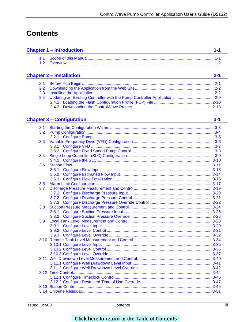
Contents
Chapter 1 – Introduction 1-1 1.1 Scope of this Manual.................................................................................................................1-1 1.2 Overview ...................................................................................................................................1-2
Chapter 2 – Installation 2-1 2.1 Before You Begin ......................................................................................................................2-1 2.2 Downloading the Application from the Web Site.......................................................................2-2 2.3 Installing the Application ...........................................................................................................2-2 2.4 Updating an Existing Controller with the Pump Controller Application .....................................2-9
2.4.1 Loading the Flash Configuration Profile (FCP) File ....................................................2-10 2.4.2 Downloading the ControlWave Project .......................................................................2-13
Chapter 3 – Configuration 3-1 3.1 Starting the Configuration Wizard .............................................................................................3-3 3.2 Pump Configuration ..................................................................................................................3-4
3.2.1 Configure Pumps ..........................................................................................................3-5 3.3 Variable Frequency Drive (VFD) Configuration ........................................................................3-6
3.3.1 Configure VFD ..............................................................................................................3-7 3.3.2 Configure Fixed Speed Pump Control ..........................................................................3-8
3.4 Single Loop Controller (SLC) Configuration..............................................................................3-9 3.4.1 Configure the SLC.......................................................................................................3-10
3.5 Station Flow.............................................................................................................................3-11 3.5.1 Configure Flow Input ...................................................................................................3-13 3.5.2 Configure Estimated Flow Input..................................................................................3-14 3.5.3 Configure Flow Totalization.........................................................................................3-15
3.6 Alarm Limit Configuration........................................................................................................3-17 3.7 Discharge Pressure Measurement and Control......................................................................3-19
3.7.1 Configure Discharge Pressure Input...........................................................................3-20 3.7.2 Configure Discharge Pressure Control .......................................................................3-21 3.7.3 Configure Discharge Pressure Override Control ........................................................3-22
3.8 Suction Pressure Measurement and Control ..........................................................................3-24 3.8.1 Configure Suction Pressure Input ...............................................................................3-25 3.8.2 Configure Suction Pressure Override .........................................................................3-26
3.9 Local Tank Level Measurement and Control ..........................................................................3-28 3.9.1 Configure Level Input ..................................................................................................3-29 3.9.2 Configure Level Control ..............................................................................................3-31 3.9.3 Configure Level Override ............................................................................................3-32
3.10 Remote Tank Level Measurement and Control ......................................................................3-34 3.10.1 Configure Level Input ..................................................................................................3-35 3.10.2 Configure Level Control ..............................................................................................3-36 3.10.3 Configure Level Override ............................................................................................3-37
3.11 Well Drawdown Level Measurement and Control...................................................................3-40 3.11.1 Configure Well Drawdown Level Input........................................................................3-41 3.11.2 Configure Well Drawdown Level Override ..................................................................3-42
3.12 Time Control............................................................................................................................3-44 3.12.1 Configure Timeclock Control.......................................................................................3-45 3.12.2 Configure Restricted Time of Use Override ................................................................3-47
3.13 Station Control.........................................................................................................................3-49 3.14 Chlorine Residual ....................................................................................................................3-51
ControlWave Pump Controller Application User’s Guide (D5132)
iv Contents Issued Oct-08
3.14.1 Configure CL2 Residual Monitor Input........................................................................3-52 3.15 Configure pH Monitor ..............................................................................................................3-53
3.15.1 Configure pH Monitor Input.........................................................................................3-54 3.16 Chemical Feed Pump..............................................................................................................3-55 3.17 Rain Gauge .............................................................................................................................3-56
3.17.1 Configure Rain Gauge Input .......................................................................................3-57 3.18 I/O Configuration .....................................................................................................................3-58
3.18.1 Configure All I/O..........................................................................................................3-59 3.18.2 Configure CL2 Probe ..................................................................................................3-64 3.18.3 Configure pH Probe ....................................................................................................3-65
3.19 Recipe .....................................................................................................................................3-66 3.19.1 Creating a Recipe .......................................................................................................3-67 3.19.2 Changing the Floating Point Format of Values ...........................................................3-68 3.19.3 Saving the Recipe.......................................................................................................3-69 3.19.4 Recalling a Saved Recipe, and Sending Its Values to the Pump Controller ..............3-69
3.20 Saving the Configuration.........................................................................................................3-70
Chapter 4 – Start Up 4-1 4.1 I/O Checkout .............................................................................................................................4-2 4.2 SLC Tuning ...............................................................................................................................4-3 4.3 Pump Checkout.........................................................................................................................4-4
4.3.1 Permissive and Interlock Details...................................................................................4-7
Chapter 5 – Operation 5-1 5.1 Fixed Speed (FS) Pump Control Settings.................................................................................5-2
Chapter 6 – Logs 6-1 6.1 View Archives............................................................................................................................6-2 6.2 View Audit Trail .........................................................................................................................6-6
6.2.1 Data Storage .................................................................................................................6-7 6.2.2 Search Criteria ..............................................................................................................6-8
6.3 Collection ..................................................................................................................................6-9
ControlWave Pump Controller Application User’s Guide (D5132)
Issued Oct-08 Introduction 1-1
Chapter 1 – Introduction
This manual explains how to install and configure the ControlWave Pump Controller application. This application may be used with either ControlWave MICRO or ControlWave Express controllers.
Chapter 1 details the structure of the manual, and discusses the basic features of the ControlWave Pump Controller application.
In This Chapter
1.1 Scope of this Manual .......................................................................1-1 1.2 Overview..........................................................................................1-2
1.1 Scope of this Manual
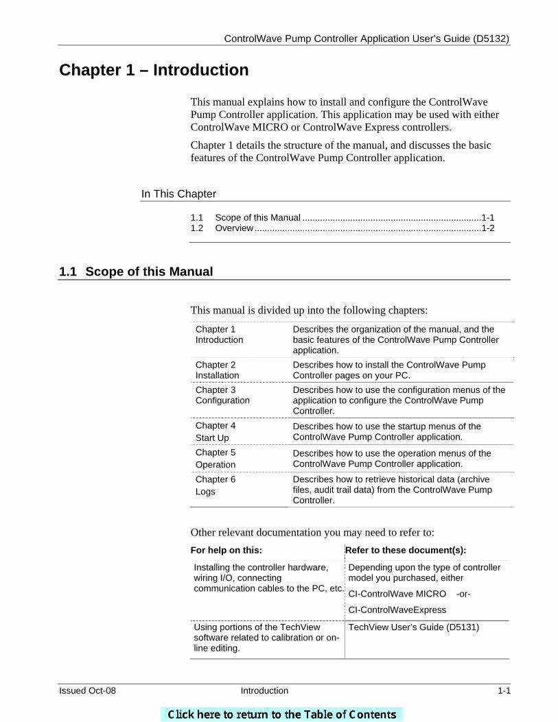
This manual is divided up into the following chapters:
Chapter 1 Introduction
Describes the organization of the manual, and the basic features of the ControlWave Pump Controller application.
Chapter 2 Installation
Describes how to install the ControlWave Pump Controller pages on your PC.
Chapter 3 Configuration
Describes how to use the configuration menus of the application to configure the ControlWave Pump Controller.
Chapter 4 Start Up
Describes how to use the startup menus of the ControlWave Pump Controller application.
Chapter 5 Operation
Describes how to use the operation menus of the ControlWave Pump Controller application.
Chapter 6 Logs
Describes how to retrieve historical data (archive files, audit trail data) from the ControlWave Pump Controller.
Other relevant documentation you may need to refer to: For help on this: Refer to these document(s):
Installing the controller hardware, wiring I/O, connecting communication cables to the PC, etc.
Depending upon the type of controller model you purchased, either
CI-ControlWave MICRO -or-
CI-ControlWaveExpress
Using portions of the TechView software related to calibration or on-line editing.
TechView User’s Guide (D5131)

ControlWave Pump Controller Application User’s Guide (D5132)
1-2 Introduction Issued Oct-08
1.2 Overview The Emerson ControlWave Pump Controller is a pre-programmed application that may be configured by the user to perform a variety of pump station control actions.
These actions include starting and stopping up to 3 fixed speed pumps based on:
a local or remote tank level indication, tank floats, local discharge and suction pressure, well drawdown level and time of day.
In addition, the fixed speed pumps may be operated to supplement a single variable frequency drive (VFD) pump.
The VFD may be operated to maintain either flow or discharge pressure setpoints.
The ControlWave Pump Controller monitors other typical parameters at a pump station, including chlorine residual, pH, and intrusion alarms.
The ControlWave Pump Controller generates alarms when any of these parameters exceed operator specified alarm limits, and maintains historical information (minimum, maximum, and averages or totals) on an hourly and daily basis.
There is no programming required to use the ControlWave Pump Controller. The user configures the controller using OpenBSI TechView, which presents operator menus for performing configuration, monitoring, and operating the pump station. Initial configuration can be done using the Configuration Wizard, which presents the user with a series of questions to be answered. After configuring the initial site, configuring additional sites can be performed by copying a previous configuration into the new ControlWave Pump Controller.

ControlWave Pump Controller Application User’s Guide (D5132)
Issued Oct-08 Introduction 1-3
The ControlWave Pump Controller is available in the following configurations:
Platform I/O Boards Configuration
ControlWave MICRO 2 Mixed I/O Boards CWM_2M
ControlWave MICRO 1 Mixed I/O Board 1 Mixed DI/O Board
CWM_1M_1D
ControlWave MICRO 1 Mixed DI/O Board 1 Mixed AI/O Board
CWM_1D_1A
ControlWave ExpressPAC
1 I/O Expansion Board
MPMP_1_0_D
Each of these configurations comes standard with two (2) RS-232 ports and one (1) RS-485 port. An Ethernet port can be added as an option to each.
A Keypad/Display is available as an option with each of these units.
The available I/O for each configuration is shown below:
Configuration DI DO DI/O AI AO HSC CNT/DI
CWM_2M 0 0 12 8 2 4 0
CWM_1M_1D 12 4 6 4 1 2 0
CWM_1D_1A 12 4 0 6 2 0 0
ExpressPAC 4 2 2 3 1 2 2

ControlWave Pump Controller Application User’s Guide (D5132)
Issued Oct-08 Installation 2-1
Chapter 2 – Installation
Chapter 2 discusses some preliminary activities which must be performed before you start, and then covers the process of loading the ControlWave Pump Controller application pages onto your PC.
In This Chapter
2.1 Before You Begin.............................................................................2-1 2.2 Downloading the Application from the Web Site .............................2-2 2.3 Installing the Application ..................................................................2-2
2.1 Before You Begin
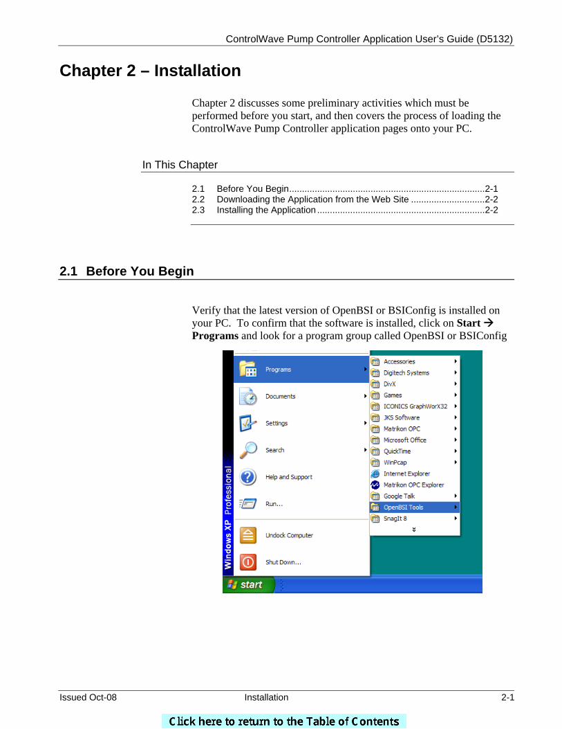
Verify that the latest version of OpenBSI or BSIConfig is installed on your PC. To confirm that the software is installed, click on Start Programs and look for a program group called OpenBSI or BSIConfig
ControlWave Pump Controller Application User’s Guide (D5132)
2-2 Installation Issued Oct-08
Verify that the ControlWave Pump Controller is wired to the field devices and power is applied to the unit.
2.2 Downloading the Application from the Web Site In your Internet browser, go to the Remote Automation Solutions web site, at the following address:
http://www.bristolbabcock.com/services/members/application_files/ap_controlwave_std_programs.htm
Download the file PUMP_APP.EXE, and save it on your desktop
2.3 Installing the Application
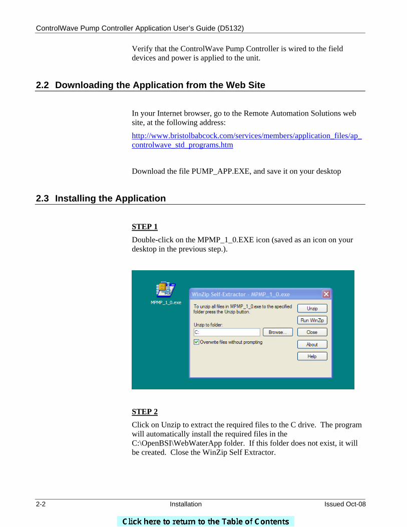
STEP 1 Double-click on the MPMP_1_0.EXE icon (saved as an icon on your desktop in the previous step.).
STEP 2 Click on Unzip to extract the required files to the C drive. The program will automatically install the required files in the C:\OpenBSI\WebWaterApp folder. If this folder does not exist, it will be created. Close the WinZip Self Extractor.
ControlWave Pump Controller Application User’s Guide (D5132)
Issued Oct-08 Installation 2-3
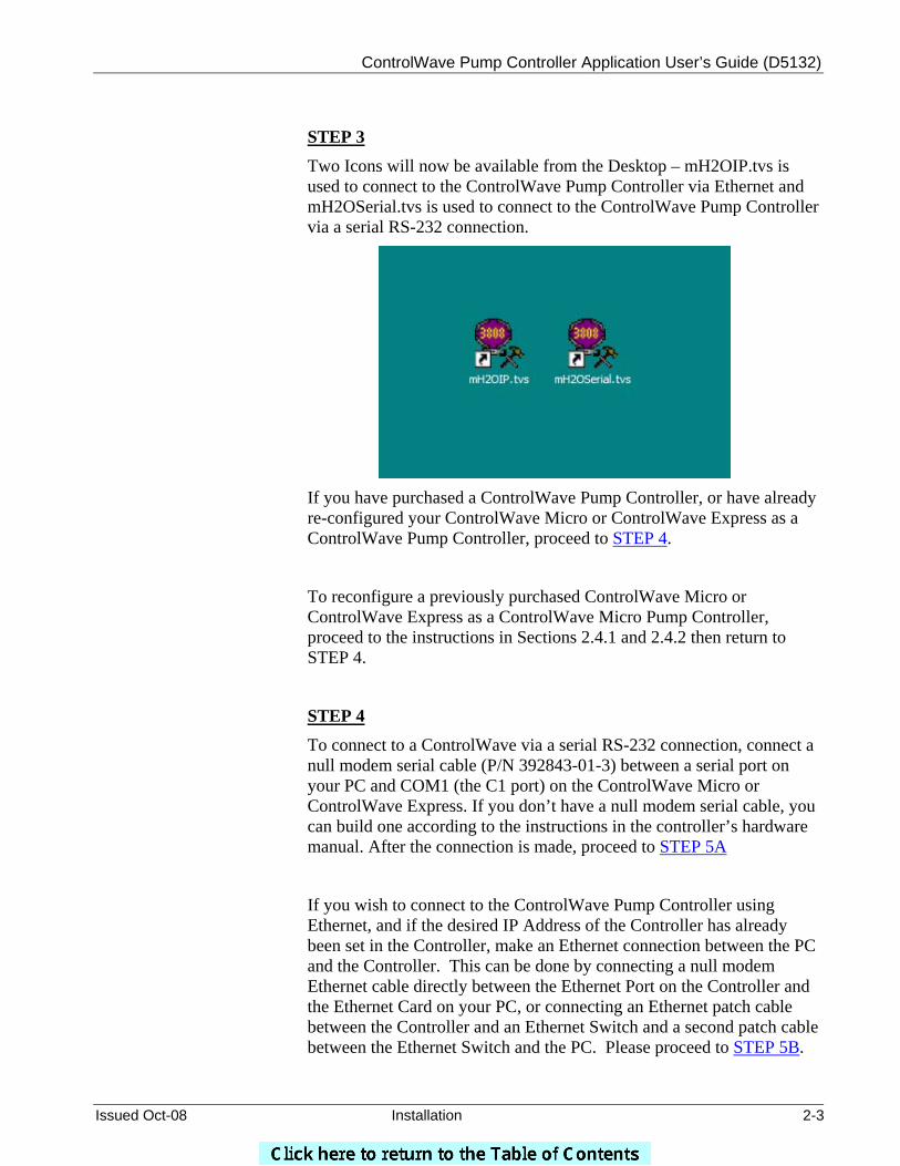
STEP 3 Two Icons will now be available from the Desktop – mH2OIP.tvs is used to connect to the ControlWave Pump Controller via Ethernet and mH2OSerial.tvs is used to connect to the ControlWave Pump Controller via a serial RS-232 connection.
If you have purchased a ControlWave Pump Controller, or have already re-configured your ControlWave Micro or ControlWave Express as a ControlWave Pump Controller, proceed to STEP 4.
To reconfigure a previously purchased ControlWave Micro or ControlWave Express as a ControlWave Micro Pump Controller, proceed to the instructions in Sections 2.4.1 and 2.4.2 then return to STEP 4.
STEP 4 To connect to a ControlWave via a serial RS-232 connection, connect a null modem serial cable (P/N 392843-01-3) between a serial port on your PC and COM1 (the C1 port) on the ControlWave Micro or ControlWave Express. If you don’t have a null modem serial cable, you can build one according to the instructions in the controller’s hardware manual. After the connection is made, proceed to STEP 5A
If you wish to connect to the ControlWave Pump Controller using Ethernet, and if the desired IP Address of the Controller has already been set in the Controller, make an Ethernet connection between the PC and the Controller. This can be done by connecting a null modem Ethernet cable directly between the Ethernet Port on the Controller and the Ethernet Card on your PC, or connecting an Ethernet patch cable between the Controller and an Ethernet Switch and a second patch cable between the Ethernet Switch and the PC. Please proceed to STEP 5B.
ControlWave Pump Controller Application User’s Guide (D5132)
2-4 Installation Issued Oct-08
If the IP Address in the Controller has not been set, follow the instructions in Section 2.4.1 and then return to STEP 5B.
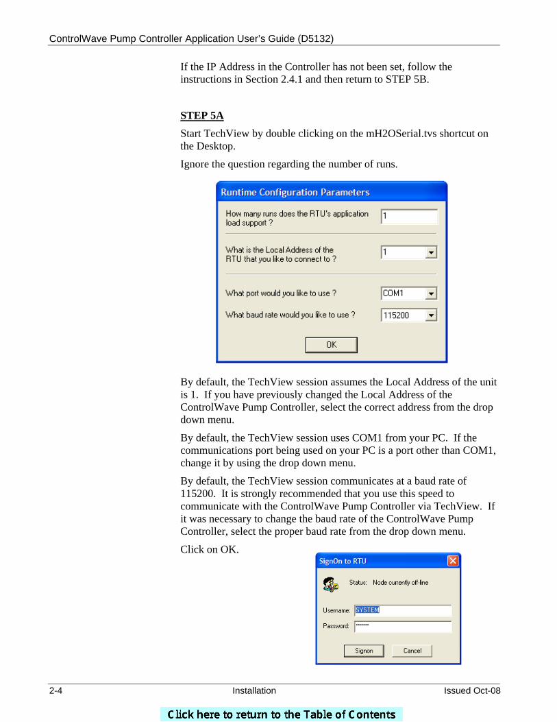
STEP 5A Start TechView by double clicking on the mH2OSerial.tvs shortcut on the Desktop.
Ignore the question regarding the number of runs.
By default, the TechView session assumes the Local Address of the unit is 1. If you have previously changed the Local Address of the ControlWave Pump Controller, select the correct address from the drop down menu.
By default, the TechView session uses COM1 from your PC. If the communications port being used on your PC is a port other than COM1, change it by using the drop down menu.
By default, the TechView session communicates at a baud rate of 115200. It is strongly recommended that you use this speed to communicate with the ControlWave Pump Controller via TechView. If it was necessary to change the baud rate of the ControlWave Pump Controller, select the proper baud rate from the drop down menu.
Click on OK.
ControlWave Pump Controller Application User’s Guide (D5132)
Issued Oct-08 Installation 2-5
You will be prompted for a Username and Password. By default, the Username is SYSTEM and the Password is 666666. Enter the Username and Password and click on Signon.
Proceed to STEP 6
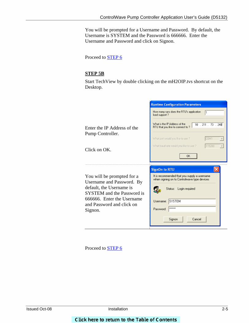
STEP 5B Start TechView by double clicking on the mH2OIP.tvs shortcut on the Desktop.
Enter the IP Address of the Pump Controller.
Click on OK.
You will be prompted for a Username and Password. By default, the Username is SYSTEM and the Password is 666666. Enter the Username and Password and click on Signon.
Proceed to STEP 6
ControlWave Pump Controller Application User’s Guide (D5132)
2-6 Installation Issued Oct-08
STEP 6
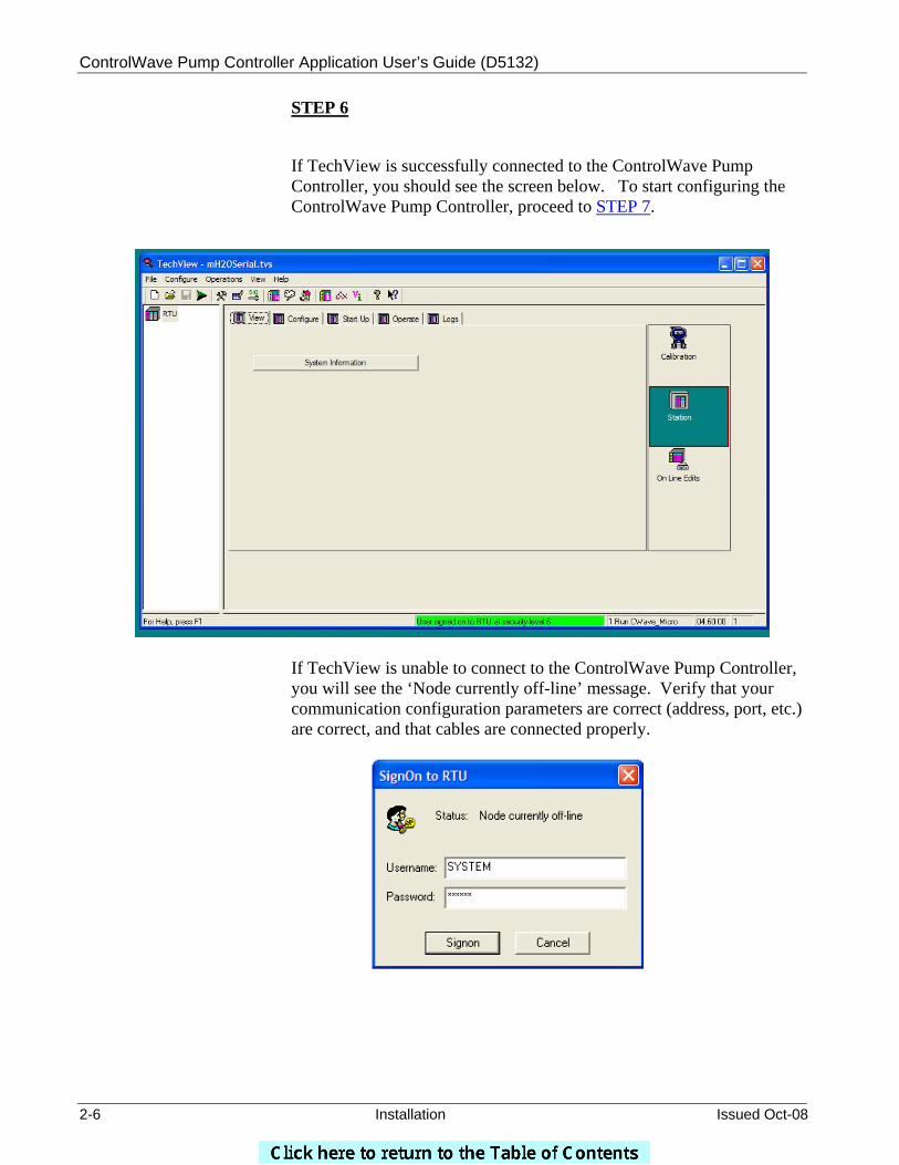
If TechView is successfully connected to the ControlWave Pump Controller, you should see the screen below. To start configuring the ControlWave Pump Controller, proceed to STEP 7.
If TechView is unable to connect to the ControlWave Pump Controller, you will see the ‘Node currently off-line’ message. Verify that your communication configuration parameters are correct (address, port, etc.) are correct, and that cables are connected properly.
ControlWave Pump Controller Application User’s Guide (D5132)
Issued Oct-08 Installation 2-7
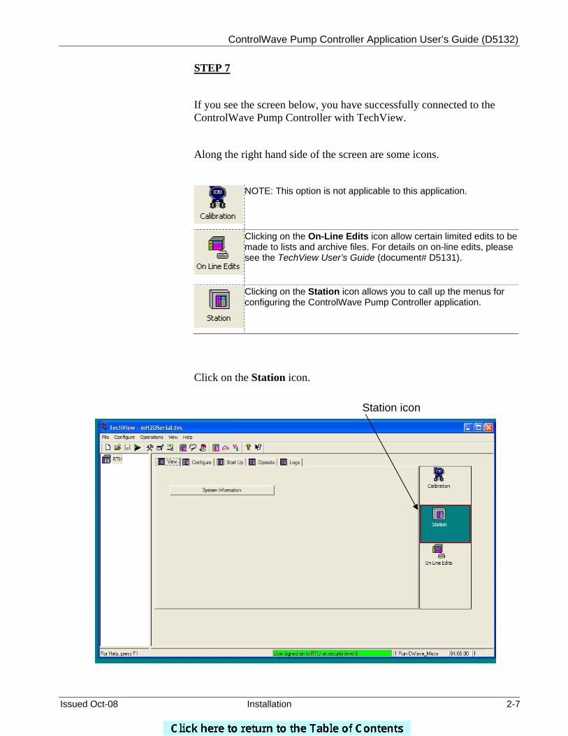
STEP 7
If you see the screen below, you have successfully connected to the ControlWave Pump Controller with TechView.
Along the right hand side of the screen are some icons.
NOTE: This option is not applicable to this application.
Clicking on the On-Line Edits icon allow certain limited edits to be made to lists and archive files. For details on on-line edits, please see the TechView User’s Guide (document# D5131).
Clicking on the Station icon allows you to call up the menus for configuring the ControlWave Pump Controller application.
Click on the Station icon.
Station icon
ControlWave Pump Controller Application User’s Guide (D5132)
2-8 Installation Issued Oct-08
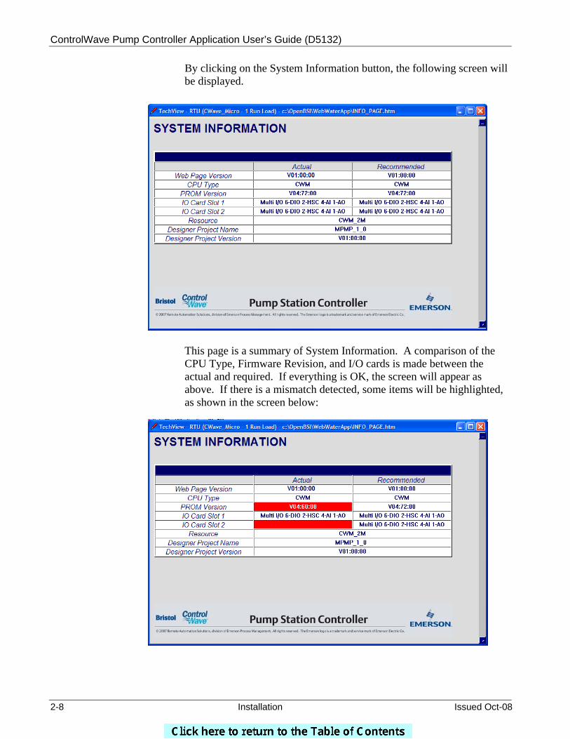
By clicking on the System Information button, the following screen will be displayed.
This page is a summary of System Information. A comparison of the CPU Type, Firmware Revision, and I/O cards is made between the actual and required. If everything is OK, the screen will appear as above. If there is a mismatch detected, some items will be highlighted, as shown in the screen below:
ControlWave Pump Controller Application User’s Guide (D5132)
Issued Oct-08 Installation 2-9
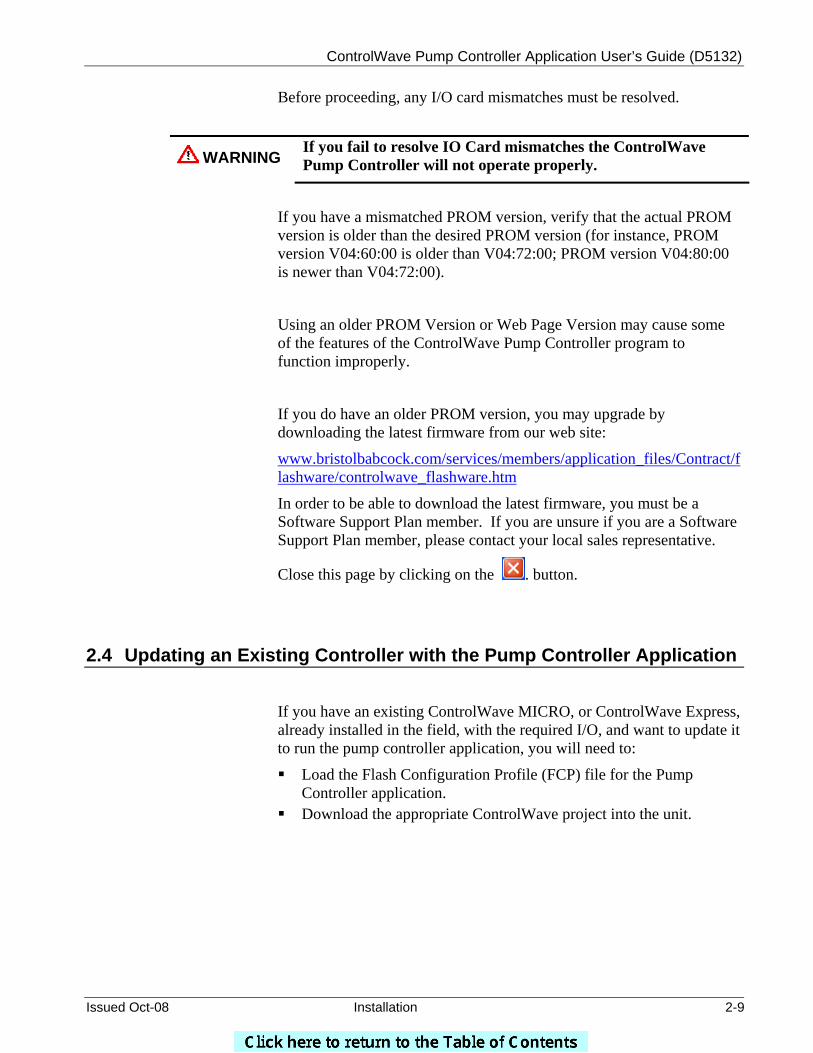
Before proceeding, any I/O card mismatches must be resolved.
WARNING If you fail to resolve IO Card mismatches the ControlWave Pump Controller will not operate properly.
If you have a mismatched PROM version, verify that the actual PROM version is older than the desired PROM version (for instance, PROM version V04:60:00 is older than V04:72:00; PROM version V04:80:00 is newer than V04:72:00).
Using an older PROM Version or Web Page Version may cause some of the features of the ControlWave Pump Controller program to function improperly.
If you do have an older PROM version, you may upgrade by downloading the latest firmware from our web site:
www.bristolbabcock.com/services/members/application_files/Contract/flashware/controlwave_flashware.htm
In order to be able to download the latest firmware, you must be a Software Support Plan member. If you are unsure if you are a Software Support Plan member, please contact your local sales representative.
Close this page by clicking on the . button.
2.4 Updating an Existing Controller with the Pump Controller Application
If you have an existing ControlWave MICRO, or ControlWave Express, already installed in the field, with the required I/O, and want to update it to run the pump controller application, you will need to:
Load the Flash Configuration Profile (FCP) file for the Pump Controller application.
Download the appropriate ControlWave project into the unit.
ControlWave Pump Controller Application User’s Guide (D5132)
2-10 Installation Issued Oct-08
2.4.1 Loading the Flash Configuration Profile (FCP) File
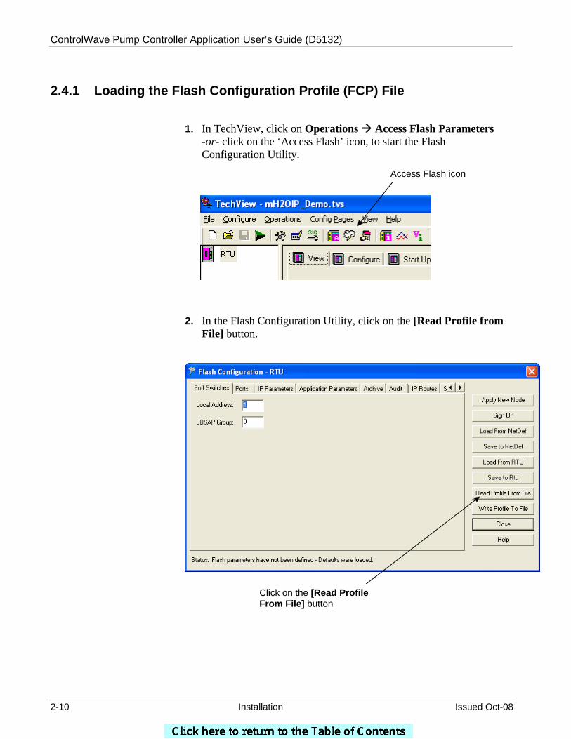
1. In TechView, click on Operations Access Flash Parameters -or- click on the ‘Access Flash’ icon, to start the Flash Configuration Utility.
2. In the Flash Configuration Utility, click on the [Read Profile from File] button.
Access Flash icon
Click on the [Read Profile From File] button
ControlWave Pump Controller Application User’s Guide (D5132)
Issued Oct-08 Installation 2-11
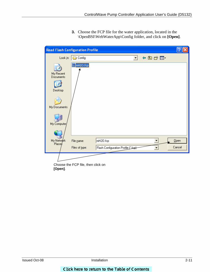
3. Choose the FCP file for the water application, located in the \OpenBSI\WebWaterApp\Config folder, and click on [Open].
Choose the FCP file, then click on [Open].
ControlWave Pump Controller Application User’s Guide (D5132)
2-12 Installation Issued Oct-08
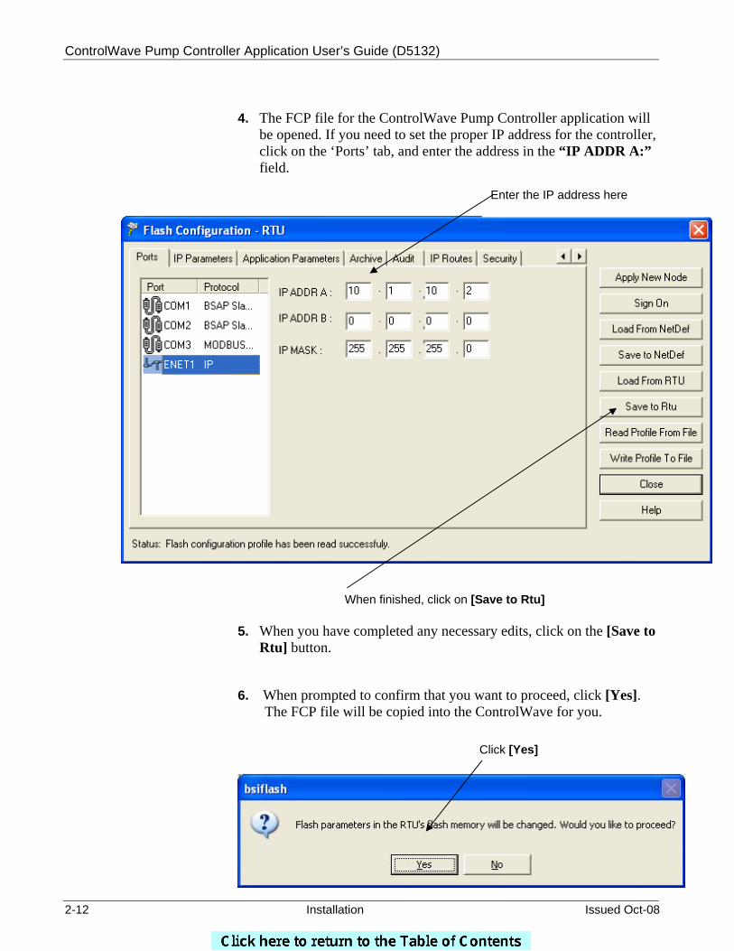
4. The FCP file for the ControlWave Pump Controller application will
be opened. If you need to set the proper IP address for the controller, click on the ‘Ports’ tab, and enter the address in the “IP ADDR A:” field.
5. When you have completed any necessary edits, click on the [Save to
Rtu] button.
6. When prompted to confirm that you want to proceed, click [Yes]. The FCP file will be copied into the ControlWave for you.
Enter the IP address here
When finished, click on [Save to Rtu]
Click [Yes]
ControlWave Pump Controller Application User’s Guide (D5132)
Issued Oct-08 Installation 2-13
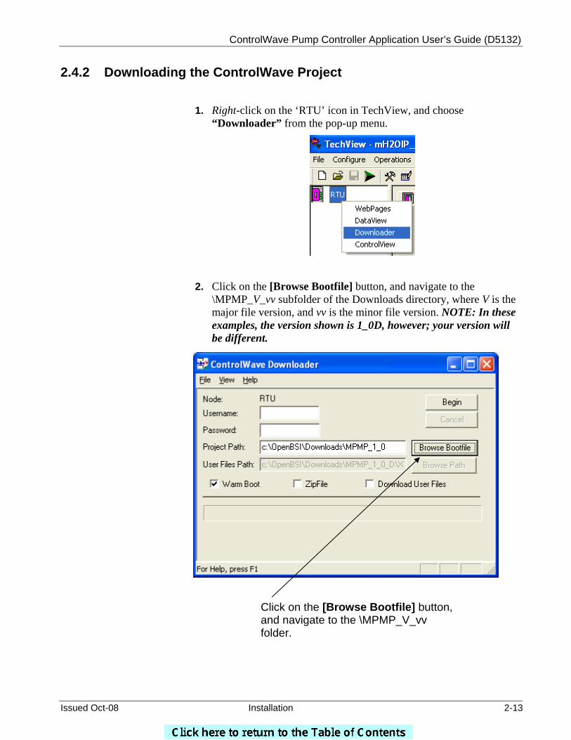
2.4.2 Downloading the ControlWave Project
1. Right-click on the ‘RTU’ icon in TechView, and choose “Downloader” from the pop-up menu.
2. Click on the [Browse Bootfile] button, and navigate to the \MPMP_V_vv subfolder of the Downloads directory, where V is the major file version, and vv is the minor file version. NOTE: In these examples, the version shown is 1_0D, however; your version will be different.
Click on the [Browse Bootfile] button, and navigate to the \MPMP_V_vv folder.
ControlWave Pump Controller Application User’s Guide (D5132)
2-14 Installation Issued Oct-08
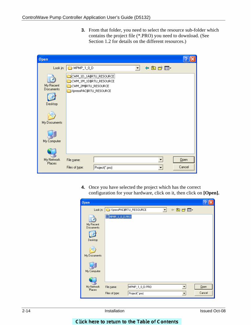
3. From that folder, you need to select the resource sub-folder which contains the project file (*.PRO) you need to download. (See Section 1.2 for details on the different resources.)
4. Once you have selected the project which has the correct configuration for your hardware, click on it, then click on [Open].
ControlWave Pump Controller Application User’s Guide (D5132)
Issued Oct-08 Installation 2-15
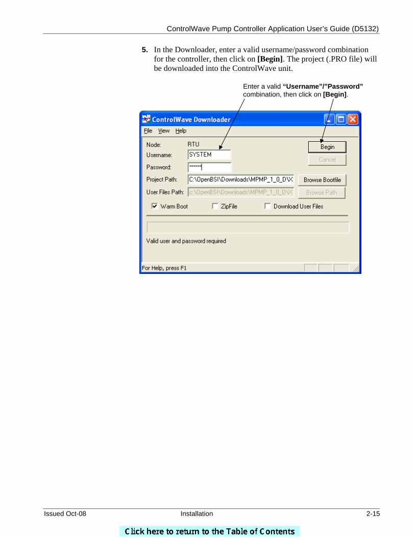
5. In the Downloader, enter a valid username/password combination for the controller, then click on [Begin]. The project (.PRO file) will be downloaded into the ControlWave unit.
Enter a valid “Username”/”Password” combination, then click on [Begin].

ControlWave Pump Controller Application User’s Guide (D5132)
Issued Oct-08 Configuration 3-1
Chapter 3 – Configuration
This chapter covers the steps necessary to configure the ControlWave Pump Controller application.
In This Chapter
3.1 Starting the Configuration Wizard....................................................3-3 3.2 Pump Configuration .........................................................................3-4
3.2.1 Configure Pumps..................................................................3-5 3.3 Variable Frequency Drive (VFD) Configuration ...............................3-6
3.3.1 Configure VFD......................................................................3-7 3.3.2 Configure Fixed Speed Pump Control .................................3-8
3.4 SLC Configuration ...........................................................................3-9 3.4.1 Configure the SLC..............................................................3-10
3.5 Station Flow ...................................................................................3-11 3.5.1 Configure Flow Input ..........................................................3-13 3.5.2 Configure Estimated Flow Input .........................................3-14 3.5.3 Configure Flow Totalization................................................3-15
3.6 Alarm Limit Configuration ..............................................................3-17 3.7 Discharge Pressure Measurement and Control ............................3-19
3.7.1 Configure Discharge Pressure Input ..................................3-20 3.7.2 Configure Discharge Pressure Control ..............................3-21 3.7.3 Configure Discharge Pressure Override Control................3-22
3.8 Suction Pressure Measurement and Control.................................3-24 3.8.1 Configure Suction Pressure Input ......................................3-25 3.8.2 Configure Suction Pressure Override ................................3-26
3.9 Local Tank Level Measurement and Control.................................3-28 3.9.1 Configure Level Input .........................................................3-29 3.9.2 Configure Level Control......................................................3-31 3.9.3 Configure Level Override ...................................................3-32
3.10 Remote Tank Level Measurement and Control.............................3-34 3.10.1 Configure Level Input .........................................................3-35 3.10.2 Configure Level Control......................................................3-36 3.10.3 Configure Level Override ...................................................3-37
3.11 Well Drawdown Level Measurement and Control .........................3-40 3.11.1 Configure Well Drawdown Level Input ...............................3-41 3.11.2 Configure Well Drawdown Level Override .........................3-42
3.12 Time Control ..................................................................................3-44 3.12.1 Configure Timeclock Control ..............................................3-45 3.12.2 Configure Restricted Time of Use Override .......................3-47
3.13 Station Control ...............................................................................3-49 3.14 Chlorine Residual ..........................................................................3-51
3.14.1 Configure CL2 Residual Monitor Input ...............................3-52 3.15 Configure pH Monitor.....................................................................3-53
3.15.1 Configure pH Monitor Input ................................................3-54 3.16 Chemical Feed Pump ....................................................................3-55 3.17 Rain Gauge....................................................................................3-56
3.17.1 Configure Rain Gauge Input...............................................3-57 3.18 I/O Configuration............................................................................3-58
3.18.1 Configure All I/O .................................................................3-59 3.18.2 Configure CL2 Probe..........................................................3-64 3.18.3 Configure pH Probe............................................................3-65
3.19 Recipe............................................................................................3-66 3.19.1 Creating a Recipe...............................................................3-67

ControlWave Pump Controller Application User’s Guide (D5132)
3-2 Configuration Issued Oct-08
3.19.2 Changing the Floating Point Format of Values ..................3-68 3.19.3 Saving the Recipe ..............................................................3-69 3.19.4 Recalling a Saved Recipe, and Sending Its Values to the Pump
Controller............................................................................3-69 3.20 Saving the Configuration ...............................................................3-70
To configure the ControlWave Pump Controller, click on the Configure tab and then click on the Station Configuration Wizard button.
The System Information screen was discussed earlier in Section 2.3.
This will open the Configuration Wizard screens.
First, click on the ‘Configure’ tab, then click on the Station Configuration Wizard button.
ControlWave Pump Controller Application User’s Guide (D5132)
Issued Oct-08 Configuration 3-3
3.1 Starting the Configuration Wizard
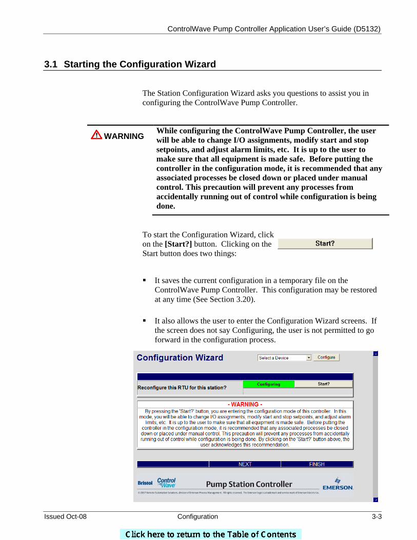
The Station Configuration Wizard asks you questions to assist you in configuring the ControlWave Pump Controller.
WARNING While configuring the ControlWave Pump Controller, the user will be able to change I/O assignments, modify start and stop setpoints, and adjust alarm limits, etc. It is up to the user to make sure that all equipment is made safe. Before putting the controller in the configuration mode, it is recommended that any associated processes be closed down or placed under manual control. This precaution will prevent any processes from accidentally running out of control while configuration is being done.
To start the Configuration Wizard, click on the [Start?] button. Clicking on the Start button does two things:
It saves the current configuration in a temporary file on the ControlWave Pump Controller. This configuration may be restored at any time (See Section 3.20).
It also allows the user to enter the Configuration Wizard screens. If
the screen does not say Configuring, the user is not permitted to go forward in the configuration process.
ControlWave Pump Controller Application User’s Guide (D5132)
3-4 Configuration Issued Oct-08
There are two ways to navigate through the Configuration Wizard:
Click on the NEXT button at the bottom of each page to sequentially move through the configuration, -or-
Use the ‘Select a Device’ drop down menu, to choose a particular
item to configure, and then click on Configure. (This option is accessible from all of the main configuration pages, and allows the user to quickly navigate the system to make changes to a particular item.)
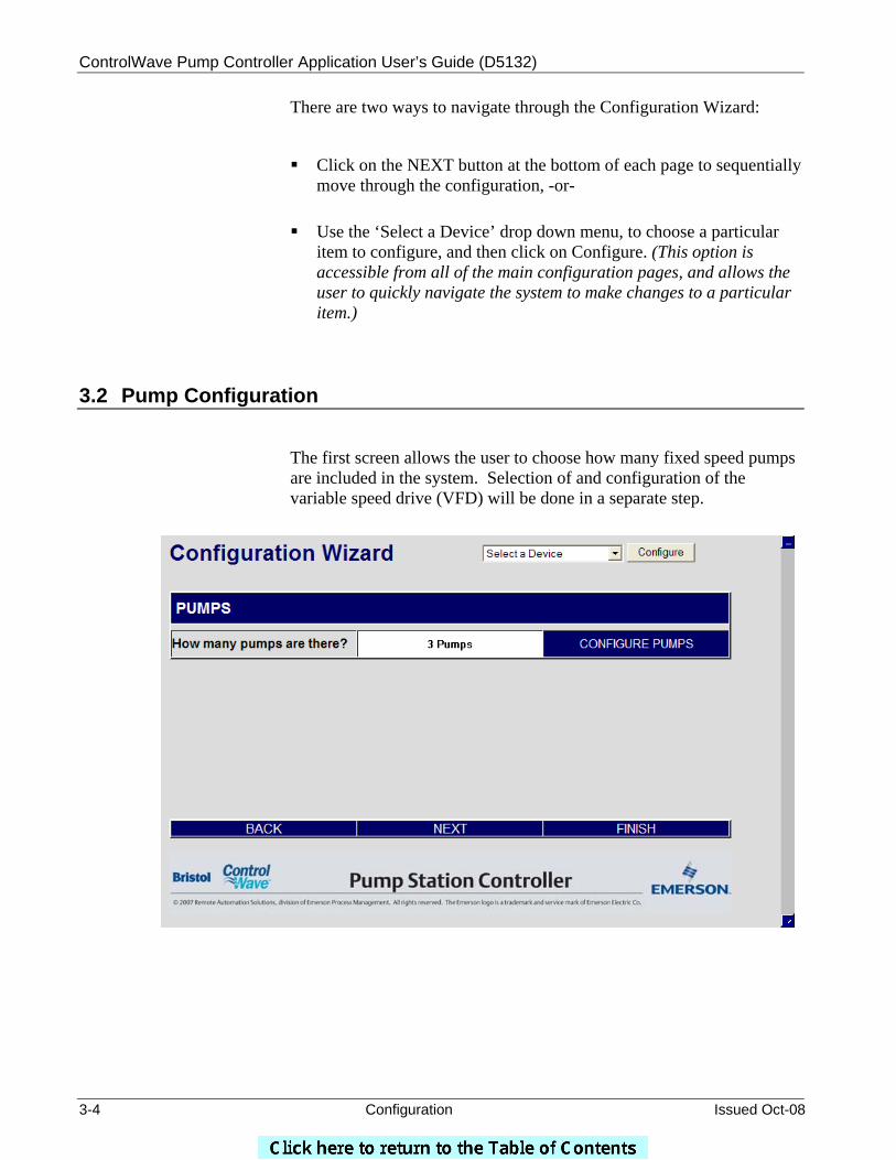
3.2 Pump Configuration
The first screen allows the user to choose how many fixed speed pumps are included in the system. Selection of and configuration of the variable speed drive (VFD) will be done in a separate step.
ControlWave Pump Controller Application User’s Guide (D5132)
Issued Oct-08 Configuration 3-5
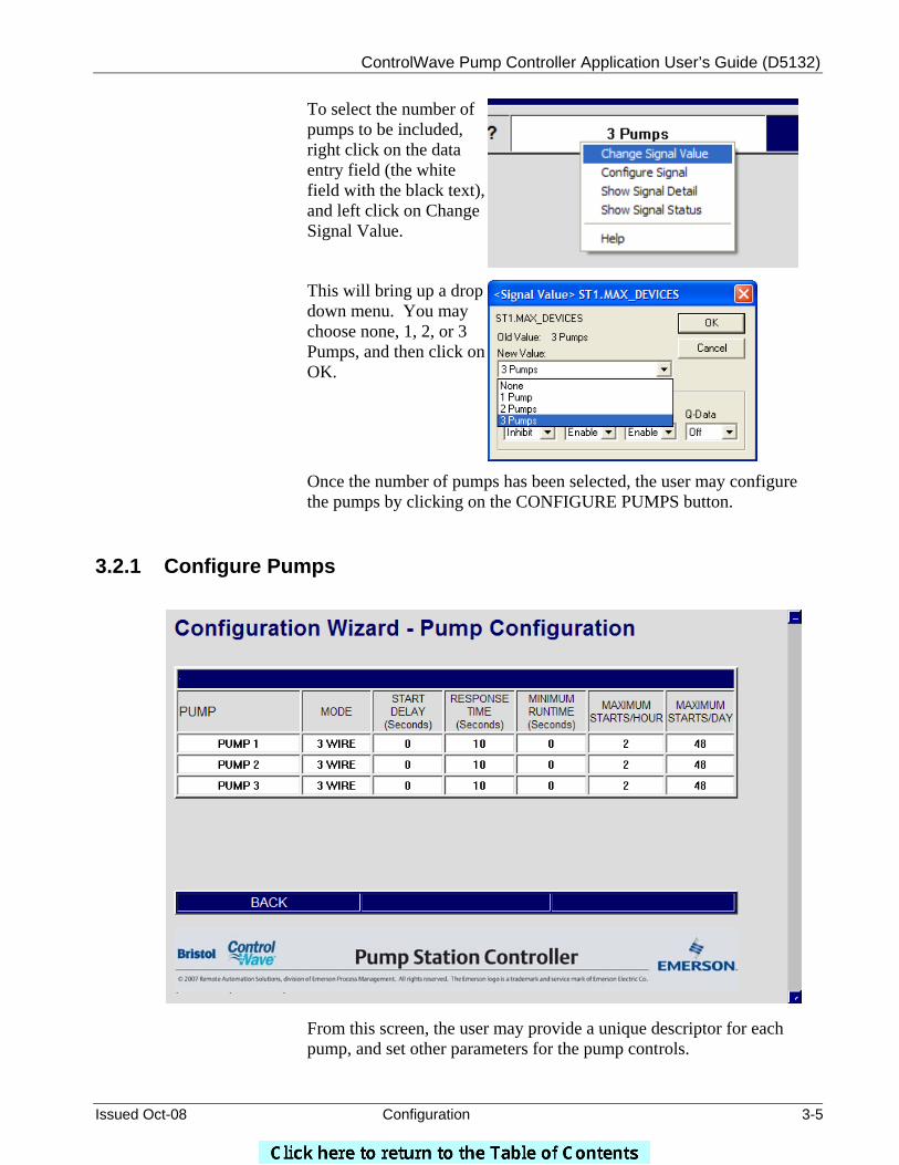
To select the number of pumps to be included, right click on the data entry field (the white field with the black text), and left click on Change Signal Value.
This will bring up a drop down menu. You may choose none, 1, 2, or 3 Pumps, and then click on OK.
Once the number of pumps has been selected, the user may configure the pumps by clicking on the CONFIGURE PUMPS button.
3.2.1 Configure Pumps
From this screen, the user may provide a unique descriptor for each pump, and set other parameters for the pump controls.
ControlWave Pump Controller Application User’s Guide (D5132)
3-6 Configuration Issued Oct-08
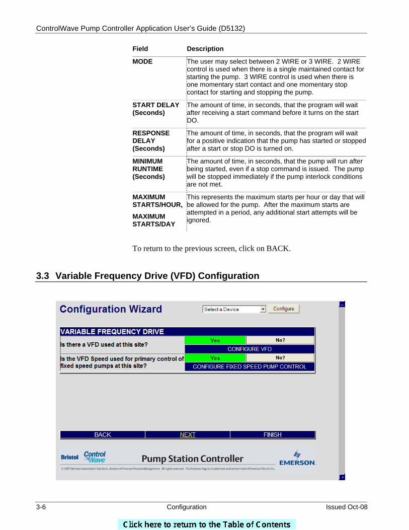
Field Description
MODE
The user may select between 2 WIRE or 3 WIRE. 2 WIRE control is used when there is a single maintained contact for starting the pump. 3 WIRE control is used when there is one momentary start contact and one momentary stop contact for starting and stopping the pump.
START DELAY (Seconds)
The amount of time, in seconds, that the program will wait after receiving a start command before it turns on the start DO.
RESPONSE DELAY (Seconds)
The amount of time, in seconds, that the program will wait for a positive indication that the pump has started or stoppedafter a start or stop DO is turned on.
MINIMUM RUNTIME (Seconds)
The amount of time, in seconds, that the pump will run after being started, even if a stop command is issued. The pump will be stopped immediately if the pump interlock conditions are not met.
MAXIMUM STARTS/HOUR,
MAXIMUM STARTS/DAY
This represents the maximum starts per hour or day that will be allowed for the pump. After the maximum starts are attempted in a period, any additional start attempts will be ignored.
To return to the previous screen, click on BACK.
3.3 Variable Frequency Drive (VFD) Configuration
ControlWave Pump Controller Application User’s Guide (D5132)
Issued Oct-08 Configuration 3-7
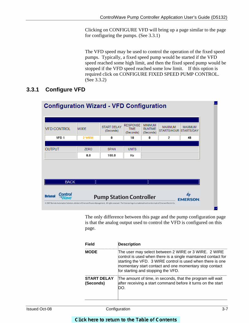
Clicking on CONFIGURE VFD will bring up a page similar to the page for configuring the pumps. (See 3.3.1)
The VFD speed may be used to control the operation of the fixed speed pumps. Typically, a fixed speed pump would be started if the VFD speed reached some high limit, and then the fixed speed pump would be stopped if the VFD speed reached some low limit. If this option is required click on CONFIGURE FIXED SPEED PUMP CONTROL. (See 3.3.2)
3.3.1 Configure VFD
The only difference between this page and the pump configuration page is that the analog output used to control the VFD is configured on this page.
Field Description
MODE
The user may select between 2 WIRE or 3 WIRE. 2 WIRE control is used when there is a single maintained contact for starting the VFD. 3 WIRE control is used when there is one momentary start contact and one momentary stop contact for starting and stopping the VFD.
START DELAY (Seconds)
The amount of time, in seconds, that the program will wait after receiving a start command before it turns on the start DO.
ControlWave Pump Controller Application User’s Guide (D5132)
3-8 Configuration Issued Oct-08
RESPONSE DELAY (Seconds)
The amount of time, in seconds, that the program will wait for a positive indication that the VFD has started or stopped after a start or stop DO is turned on.
MINIMUM RUNTIME (Seconds)
The amount of time, in seconds, that the VFD will run after being started, even if a stop command is issued. The VFD will be stopped immediately if the pump interlock conditions are not met.
MAXIMUM STARTS/HOUR,
MAXIMUM STARTS/DAY
This represents the maximum starts per hour or day that will be allowed for the VFD. After the maximum starts are attempted in a period, any additional start attempts will be ignored.
OUTPUT ZERO This is the speed command sent to the VFD when the output is 4 mA or 1 Volt.
OUTPUT SPAN The difference between the value of the speed command at 4 mA (or 1 volt) and its value at 20 mA (5 volts). For instance, if the ZERO is 5.0 Hz and the SPAN is 85.0 Hz, the SPAN is 80.0.
OUTPUT UNITS This is the engineering units of the speed command.
To return to the VFD screen, click on BACK.
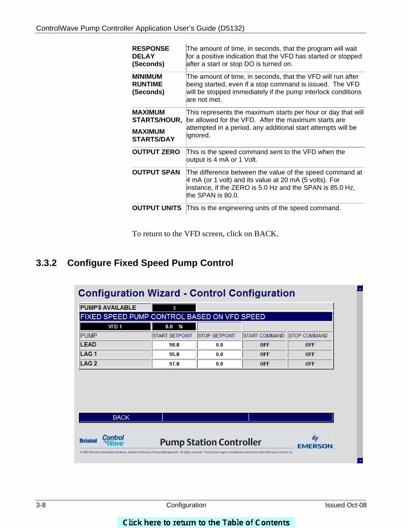
3.3.2 Configure Fixed Speed Pump Control
ControlWave Pump Controller Application User’s Guide (D5132)
Issued Oct-08 Configuration 3-9
Depending on the number of fixed speed pumps configured, the user may assign up to three start setpoints and three stop setpoints, to control the operation of the fixed speed pumps.
Field Description
START SETPOINT
If the actual VFD speed exceeds this value, the START COMMAND will be activated to start the associated fixed speed pump.
STOP SETPOINT
If the actual VFD speed falls below this value, the STOP COMMAND will be activated to stop the associated fixed speed pump.
START COMMAND
The START command is activated (and displays ‘START’ in this field) when the actual VFD speed exceeds the START SETPOINT. Otherwise, this field displays ‘OFF’.
STOP COMMAND
The STOP command is activated (and displays ‘STOP’ in this field) when the actual VFD speed falls below the STOP SETPOINT. Otherwise, this field displays ‘OFF’.
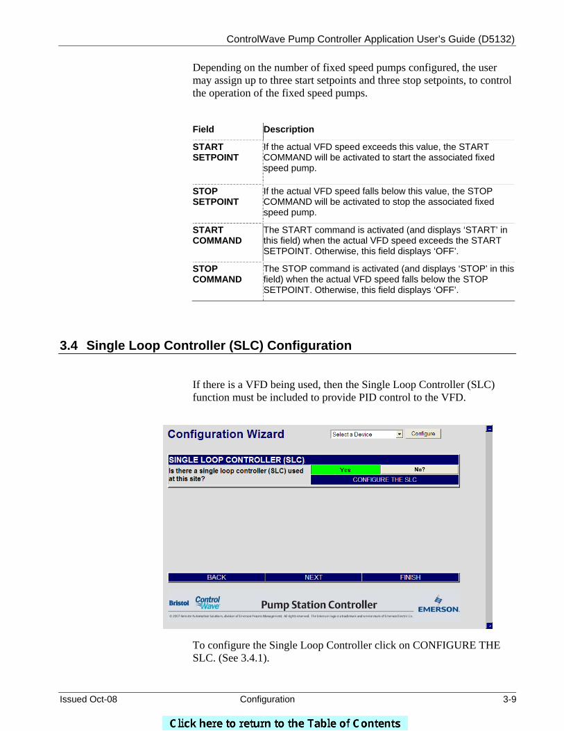
3.4 Single Loop Controller (SLC) Configuration
If there is a VFD being used, then the Single Loop Controller (SLC) function must be included to provide PID control to the VFD.
To configure the Single Loop Controller click on CONFIGURE THE SLC. (See 3.4.1).
ControlWave Pump Controller Application User’s Guide (D5132)
3-10 Configuration Issued Oct-08
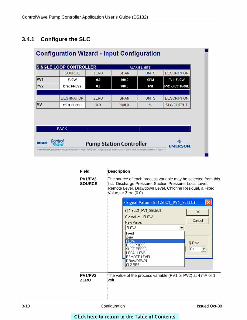
3.4.1 Configure the SLC
Field Description
PV1/PV2 SOURCE
The source of each process variable may be selected from this list: Discharge Pressure, Suction Pressure, Local Level, Remote Level, Drawdown Level, Chlorine Residual, a Fixed Value, or Zero (0.0)
PV1/PV2 ZERO
The value of the process variable (PV1 or PV2) at 4 mA or 1 volt.
ControlWave Pump Controller Application User’s Guide (D5132)
Issued Oct-08 Configuration 3-11
PV1/PV2 SPAN
The difference between the value of the process variable (PV1 or PV2) at 4 mA (or 1 volt) and its value at 20 mA (5 volts). For instance, if the ZERO is 0.0 GPM and the flow rate at 20 mA is 150.0 GPM, the SPAN is 150.0. If the ZERO is 15.0 GPM and the flow rate at 20 mA is 150.0 GPM, the SPAN is 135.0.
PV1/PV2 UNITS
The engineering units of the process variable (PV1 or PV2).
PV1/PV2 DESCRIPTION
A textual description of the process variable (PV1 or PV2)
MV DESTINATION
The destination of the manipulated variable (MV) is currently the VFD1 speed.
MV ZERO The value of the manipulated variable (MV) at 4 mA or 1 volt.
MV SPAN The difference between the value of the manipulated variable (MV) at 4 mA (or 1 volt) and its value at 20 mA (5 volts). For instance, if the ZERO is 0.0 GPM and the flow rate at 20 mA is 150.0 GPM, the SPAN is 150.0. If the ZERO is 15.0 GPM and the flow rate at 20 mA is 150.0 GPM, the SPAN is 135.0.
MV DESCRIPTION
A textual description of the manipulated variable (MV).
Tuning of the Single Loop Controller PID loops is done via the Startup or Operate pages.
To configure alarm limits, click on ALARM LIMITS. (See Section 3.6 for details.)
When finished, click on BACK.
3.5 Station Flow
The ControlWave Pump Controller will perform flow measurement in a variety of ways:
If there is an analog flow transmitter available, the flow rate measurement and flow totalization will be performed via an analog input to the ControlWave Pump Controller.
If there is a pulse type flow meter (turbine meter, ultrasonic meter,
propeller meter) the flow rate measurement and flow totalization will be performed via a high speed counter input to the ControlWave Pump Controller.

ControlWave Pump Controller Application User’s Guide (D5132)
3-12 Configuration Issued Oct-08
There are some flow meters that offer an analog variable for flow
rate and a pulse signal for flow totalization. In this case, both an analog input and a high speed counter input would be used on the ControlWave Pump Controller.
Finally, there are some systems where there is no flow measurement
device at all, but flow can be estimated based on the run status of the pumps.
To configure the Flow Rate Input from an analog transmitter, click on CONFIGURE FLOW INPUT and see Section 3.5.1.
To configure Estimated Flow, Click on ESTIMATE FLOW? button, then click on CONFIGURE ESTIMATED FLOW INPUT and see Section 3.5.2.
To configure flow totalization, click on CONFIGURE FLOW TOTALIZATION and see Section 3.5.3.
ControlWave Pump Controller Application User’s Guide (D5132)
Issued Oct-08 Configuration 3-13
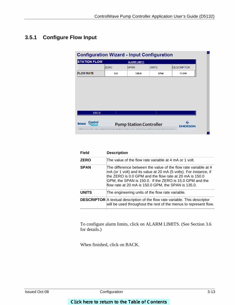
3.5.1 Configure Flow Input
Field Description
ZERO The value of the flow rate variable at 4 mA or 1 volt.
SPAN
The difference between the value of the flow rate variable at 4 mA (or 1 volt) and its value at 20 mA (5 volts). For instance, if the ZERO is 0.0 GPM and the flow rate at 20 mA is 150.0 GPM, the SPAN is 150.0. If the ZERO is 15.0 GPM and the flow rate at 20 mA is 150.0 GPM, the SPAN is 135.0.
UNITS The engineering units of the flow rate variable.
DESCRIPTOR A textual description of the flow rate variable. This descriptor will be used throughout the rest of the menus to represent flow.
To configure alarm limits, click on ALARM LIMITS. (See Section 3.6 for details.)
When finished, click on BACK.
ControlWave Pump Controller Application User’s Guide (D5132)
3-14 Configuration Issued Oct-08
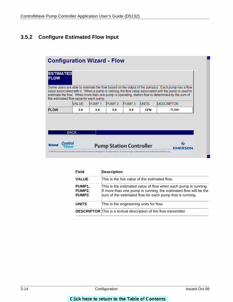
3.5.2 Configure Estimated Flow Input
Field Description
VALUE This is the live value of the estimated flow.
PUMP1, PUMP2, PUMP3
This is the estimated value of flow when each pump is running. If more than one pump is running, the estimated flow will be the sum of the estimated flow for each pump that is running.
UNITS This is the engineering units for flow.
DESCRIPTOR This is a textual description of the flow transmitter.
ControlWave Pump Controller Application User’s Guide (D5132)
Issued Oct-08 Configuration 3-15
3.5.3 Configure Flow Totalization
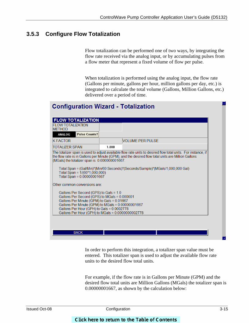
Flow totalization can be performed one of two ways, by integrating the flow rate received via the analog input, or by accumulating pulses from a flow meter that represent a fixed volume of flow per pulse.
When totalization is performed using the analog input, the flow rate (Gallons per minute, gallons per hour, million gallons per day, etc.) is integrated to calculate the total volume (Gallons, Million Gallons, etc.) delivered over a period of time.
In order to perform this integration, a totalizer span value must be entered. This totalizer span is used to adjust the available flow rate units to the desired flow total units.
For example, if the flow rate is in Gallons per Minute (GPM) and the desired flow total units are Million Gallons (MGals) the totalizer span is 0.00000001667, as shown by the calculation below:
ControlWave Pump Controller Application User’s Guide (D5132)
3-16 Configuration Issued Oct-08
TOTALIZER SPAN = (Gal/Minute) * (Minute/60 seconds) * (Seconds/Sample) * (MGals/1,000,000) GAL
TOTALIZER SPAN = 1/(60*1,000,000)
TOTALIZER SPAN = 0.00000001667
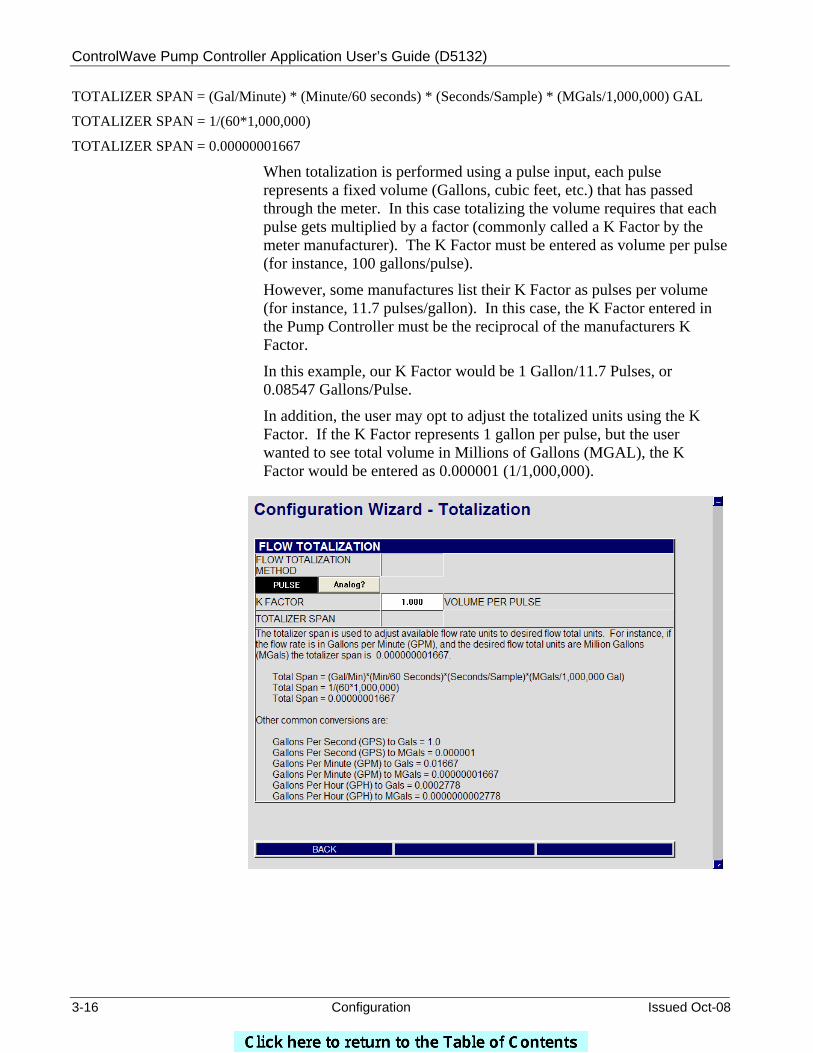
When totalization is performed using a pulse input, each pulse represents a fixed volume (Gallons, cubic feet, etc.) that has passed through the meter. In this case totalizing the volume requires that each pulse gets multiplied by a factor (commonly called a K Factor by the meter manufacturer). The K Factor must be entered as volume per pulse (for instance, 100 gallons/pulse).
However, some manufactures list their K Factor as pulses per volume (for instance, 11.7 pulses/gallon). In this case, the K Factor entered in the Pump Controller must be the reciprocal of the manufacturers K Factor.
In this example, our K Factor would be 1 Gallon/11.7 Pulses, or 0.08547 Gallons/Pulse.
In addition, the user may opt to adjust the totalized units using the K Factor. If the K Factor represents 1 gallon per pulse, but the user wanted to see total volume in Millions of Gallons (MGAL), the K Factor would be entered as 0.000001 (1/1,000,000).
ControlWave Pump Controller Application User’s Guide (D5132)
Issued Oct-08 Configuration 3-17
3.6 Alarm Limit Configuration
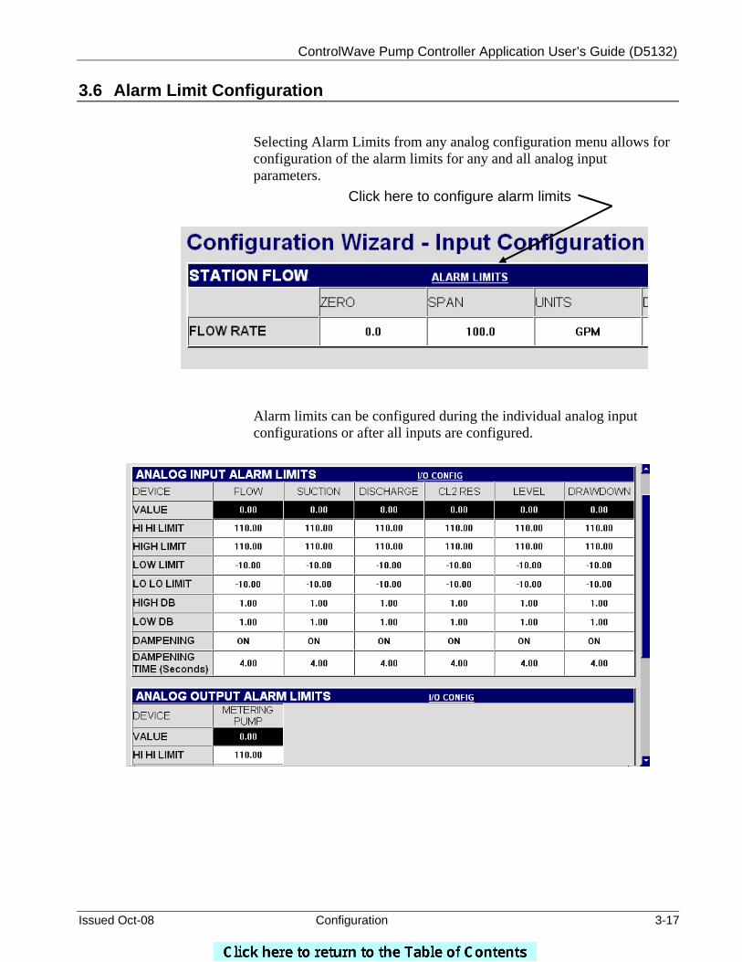
Selecting Alarm Limits from any analog configuration menu allows for configuration of the alarm limits for any and all analog input parameters.
Alarm limits can be configured during the individual analog input configurations or after all inputs are configured.
Click here to configure alarm limits
ControlWave Pump Controller Application User’s Guide (D5132)
3-18 Configuration Issued Oct-08
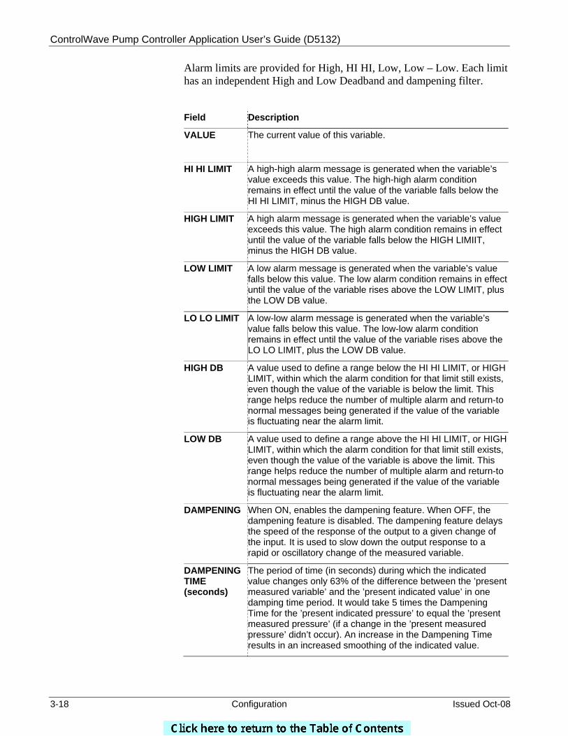
Alarm limits are provided for High, HI HI, Low, Low – Low. Each limit has an independent High and Low Deadband and dampening filter.
Field Description
VALUE
The current value of this variable.
HI HI LIMIT
A high-high alarm message is generated when the variable’s value exceeds this value. The high-high alarm condition remains in effect until the value of the variable falls below the HI HI LIMIT, minus the HIGH DB value.
HIGH LIMIT A high alarm message is generated when the variable’s value exceeds this value. The high alarm condition remains in effect until the value of the variable falls below the HIGH LIMIIT, minus the HIGH DB value.
LOW LIMIT A low alarm message is generated when the variable’s value falls below this value. The low alarm condition remains in effect until the value of the variable rises above the LOW LIMIT, plus the LOW DB value.
LO LO LIMIT A low-low alarm message is generated when the variable’s value falls below this value. The low-low alarm condition remains in effect until the value of the variable rises above the LO LO LIMIT, plus the LOW DB value.
HIGH DB A value used to define a range below the HI HI LIMIT, or HIGH LIMIT, within which the alarm condition for that limit still exists, even though the value of the variable is below the limit. This range helps reduce the number of multiple alarm and return-to normal messages being generated if the value of the variable is fluctuating near the alarm limit.
LOW DB A value used to define a range above the HI HI LIMIT, or HIGH LIMIT, within which the alarm condition for that limit still exists, even though the value of the variable is above the limit. This range helps reduce the number of multiple alarm and return-to normal messages being generated if the value of the variable is fluctuating near the alarm limit.
DAMPENING When ON, enables the dampening feature. When OFF, the dampening feature is disabled. The dampening feature delays the speed of the response of the output to a given change of the input. It is used to slow down the output response to a rapid or oscillatory change of the measured variable.
DAMPENING TIME (seconds)
The period of time (in seconds) during which the indicated value changes only 63% of the difference between the ’present measured variable’ and the ’present indicated value’ in one damping time period. It would take 5 times the Dampening Time for the ’present indicated pressure’ to equal the ’present measured pressure’ (if a change in the ’present measured pressure’ didn’t occur). An increase in the Dampening Time results in an increased smoothing of the indicated value.
ControlWave Pump Controller Application User’s Guide (D5132)
Issued Oct-08 Configuration 3-19
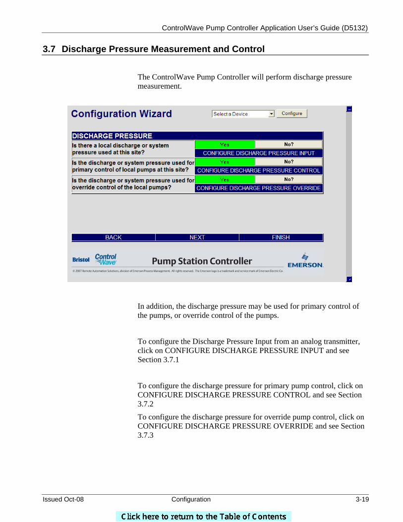
3.7 Discharge Pressure Measurement and Control
The ControlWave Pump Controller will perform discharge pressure measurement.
In addition, the discharge pressure may be used for primary control of the pumps, or override control of the pumps.
To configure the Discharge Pressure Input from an analog transmitter, click on CONFIGURE DISCHARGE PRESSURE INPUT and see Section 3.7.1
To configure the discharge pressure for primary pump control, click on CONFIGURE DISCHARGE PRESSURE CONTROL and see Section 3.7.2
To configure the discharge pressure for override pump control, click on CONFIGURE DISCHARGE PRESSURE OVERRIDE and see Section 3.7.3
ControlWave Pump Controller Application User’s Guide (D5132)
3-20 Configuration Issued Oct-08
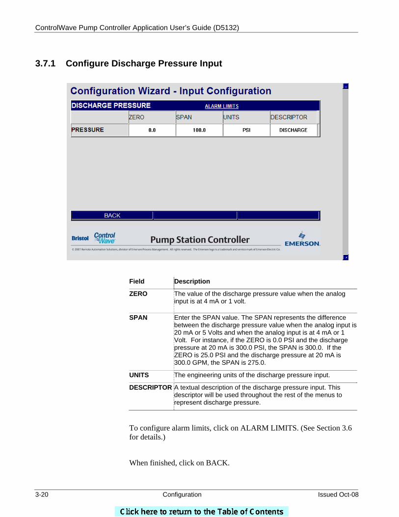
3.7.1 Configure Discharge Pressure Input
Field Description
ZERO
The value of the discharge pressure value when the analog input is at 4 mA or 1 volt.
SPAN
Enter the SPAN value. The SPAN represents the difference between the discharge pressure value when the analog input is 20 mA or 5 Volts and when the analog input is at 4 mA or 1 Volt. For instance, if the ZERO is 0.0 PSI and the discharge pressure at 20 mA is 300.0 PSI, the SPAN is 300.0. If the ZERO is 25.0 PSI and the discharge pressure at 20 mA is 300.0 GPM, the SPAN is 275.0.
UNITS The engineering units of the discharge pressure input.
DESCRIPTOR A textual description of the discharge pressure input. This descriptor will be used throughout the rest of the menus to represent discharge pressure.
To configure alarm limits, click on ALARM LIMITS. (See Section 3.6 for details.)
When finished, click on BACK.

ControlWave Pump Controller Application User’s Guide (D5132)
Issued Oct-08 Configuration 3-21
3.7.2 Configure Discharge Pressure Control
Field Description
PUMPS AVAILABLE
This represents the number of pumps available for control.
DISCHARGE
(or other name)
This is the DESCRIPTOR assigned to the Discharge Pressure Input. The field to the right is the live Discharge Pressure reading.
LEAD / LAG1 / LAG2 START SETPOINT
When the live pressure value drops below this setpoint, the appropriate pump START COMMAND will be set to START.
LEAD / LAG1 / LAG2 STOP SETPOINT
When the live pressure value rises above this setpoint, the appropriate pump STOP COMMAND will be set to STOP.
LEAD / LAG1 / LAG2 START COMMAND
When the live pressure value drops below the START SETPOINT, the corresponding START COMMAND is set to START, to start the pump. Otherwise, it is set to OFF.
LEAD / LAG1 / LAG2 STOP COMMAND
When the live pressure value rises above the STOP SETPOINT, the corresponding STOP COMMAND is set to STOP, to stop the pump. Otherwise, it is set to OFF.
To configure alarm limits, click on ALARM LIMITS. (See Section 3.6 for details.)
When finished, click on BACK.
ControlWave Pump Controller Application User’s Guide (D5132)
3-22 Configuration Issued Oct-08
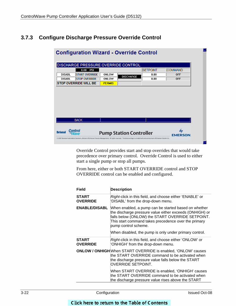
3.7.3 Configure Discharge Pressure Override Control
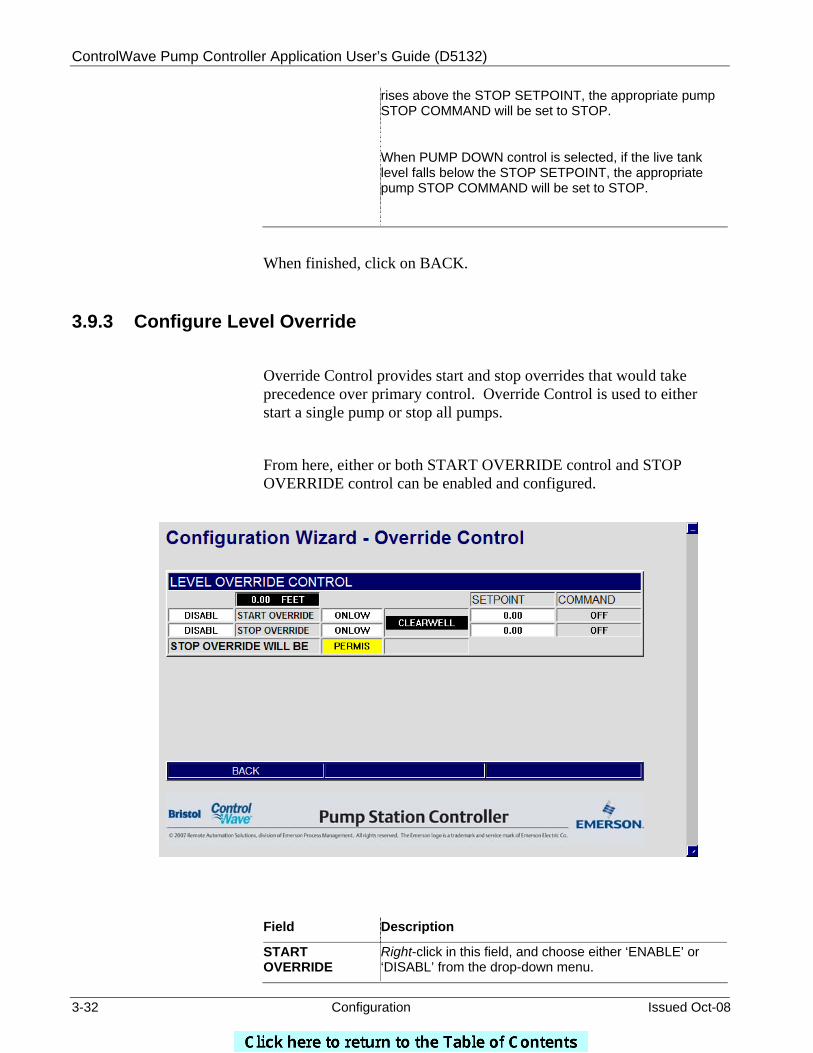
Override Control provides start and stop overrides that would take precedence over primary control. Override Control is used to either start a single pump or stop all pumps.
From here, either or both START OVERRIDE control and STOP OVERRIDE control can be enabled and configured.
Field Description
START OVERRIDE
ENABLE/DISABL
Right-click in this field, and choose either ‘ENABLE’ or ‘DISABL’ from the drop-down menu.
When enabled, a pump can be started based on whether the discharge pressure value either exceeds (ONHIGH) or falls below (ONLOW) the START OVERRIDE SETPOINT. This start command takes precedence over the primary pump control scheme.
When disabled, the pump is only under primary control.
START OVERRIDE
ONLOW / ONHIGH
Right-click in this field, and choose either ‘ONLOW’ or ‘ONHIGH’ from the drop-down menu.
When START OVERRIDE is enabled, ‘ONLOW’ causes the START OVERRIDE command to be activated when the discharge pressure value falls below the START OVERRIDE SETPOINT.
When START OVERRIDE is enabled, ‘ONHIGH’ causes the START OVERRIDE command to be activated when the discharge pressure value rises above the START

ControlWave Pump Controller Application User’s Guide (D5132)
Issued Oct-08 Configuration 3-23
OVERRIDE SETPOINT.
When START OVERRIDE is disabled, this field is ignored.
START OVERRIDE
SETPOINT
When START OVERRIDE is enabled, this is the trigger value for the discharge pressure at which a pump will be started.
When START OVERRIDE is disabled, this field is ignored.
START OVERRIDE
COMMAND
Displays ‘START’ when the START OVERRIDE condition exists or ‘OFF’ when the START OVERRIDE condition does not exist.
STOP OVERRIDE
ENABLE/DISABLE
Right-click in this field, and choose either ‘ENABLE’ or ‘DISABL’ from the drop-down menu.
When enabled, a pump can be stopped based on whether the discharge pressure value either exceeds (ONHIGH) or falls below (ONLOW) the STOP OVERRIDE SETPOINT. This stop command takes precedence over the primary pump control scheme.
When disabled, the pump is only under primary control.
STOP OVERRIDE
ONLOW / ONHIGH
Right-click in this field, and choose either ‘ONLOW’ or ‘ONHIGH’ from the drop-down menu.
When STOP OVERRIDE is enabled, ‘ONLOW’ causes the STOP OVERRIDE command to be activated when the discharge pressure value falls below the STOP OVERRIDE SETPOINT.
When STOP OVERRIDE is enabled, ‘ONHIGH’ causes the STOP OVERRIDE command to be activated when the discharge pressure value rises above the STOP OVERRIDE SETPOINT.
When STOP OVERRIDE is disabled, this field is ignored.
STOP OVERRIDE SETPOINT
When STOP OVERRIDE is enabled, this is the trigger value for the discharge pressure at which a pump will be stopped.
When STOP OVERRIDE is disabled, this field is ignored.
STOP OVERRIDE COMMAND
Displays ‘STOP’ when the STOP OVERRIDE condition exists or ‘OFF’ when the STOP OVERRIDE condition does not exist.
STOP OVERRIDE WILL BE PERMIS / INTLCK
The user can choose whether the STOP OVERRIDE is a PERMISSIVE OVERRIDE (PERMIS) or an INTERLOCKED OVERRIDE (INTLCK).
A PERMISSIVE STOP OVERRIDE may be overridden by a START OVERRIDE, but will not be overridden by a start command issued by any of the primary controls. An INTERLOCKED STOP OVERRIDE will not be overridden by any start command, whether issued by a primary control or an override control.
When finished, click on BACK.
ControlWave Pump Controller Application User’s Guide (D5132)
3-24 Configuration Issued Oct-08
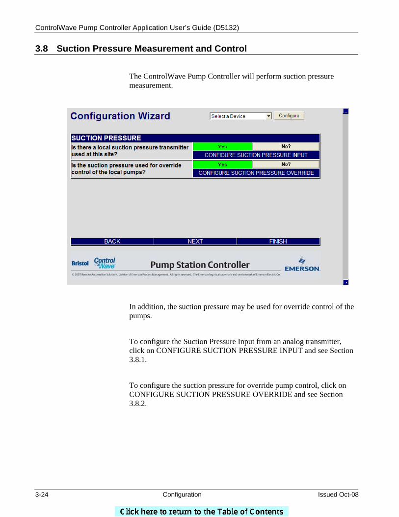
3.8 Suction Pressure Measurement and Control
The ControlWave Pump Controller will perform suction pressure measurement.
In addition, the suction pressure may be used for override control of the pumps.
To configure the Suction Pressure Input from an analog transmitter, click on CONFIGURE SUCTION PRESSURE INPUT and see Section 3.8.1.
To configure the suction pressure for override pump control, click on CONFIGURE SUCTION PRESSURE OVERRIDE and see Section 3.8.2.
ControlWave Pump Controller Application User’s Guide (D5132)
Issued Oct-08 Configuration 3-25
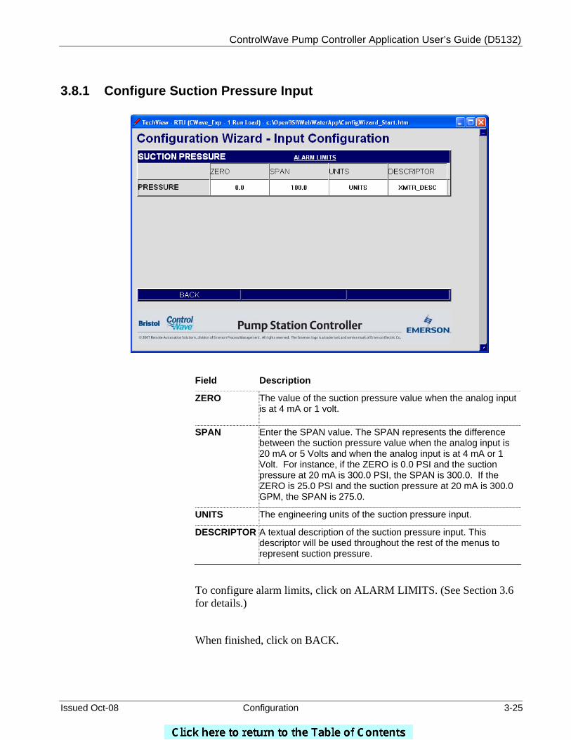
3.8.1 Configure Suction Pressure Input
Field Description
ZERO
The value of the suction pressure value when the analog input is at 4 mA or 1 volt.
SPAN
Enter the SPAN value. The SPAN represents the difference between the suction pressure value when the analog input is 20 mA or 5 Volts and when the analog input is at 4 mA or 1 Volt. For instance, if the ZERO is 0.0 PSI and the suction pressure at 20 mA is 300.0 PSI, the SPAN is 300.0. If the ZERO is 25.0 PSI and the suction pressure at 20 mA is 300.0 GPM, the SPAN is 275.0.
UNITS The engineering units of the suction pressure input.
DESCRIPTOR A textual description of the suction pressure input. This descriptor will be used throughout the rest of the menus to represent suction pressure.
To configure alarm limits, click on ALARM LIMITS. (See Section 3.6 for details.)
When finished, click on BACK.
ControlWave Pump Controller Application User’s Guide (D5132)
3-26 Configuration Issued Oct-08
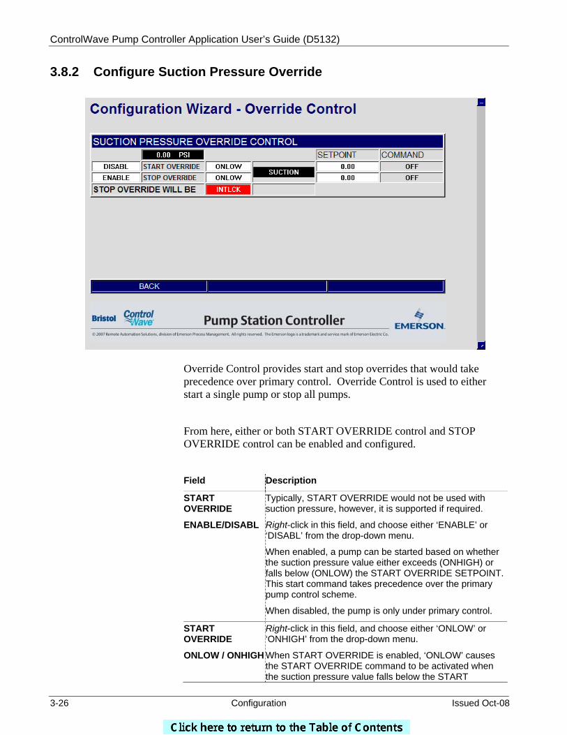
3.8.2 Configure Suction Pressure Override
Override Control provides start and stop overrides that would take precedence over primary control. Override Control is used to either start a single pump or stop all pumps.
From here, either or both START OVERRIDE control and STOP OVERRIDE control can be enabled and configured.
Field Description
START OVERRIDE
ENABLE/DISABL
Typically, START OVERRIDE would not be used with suction pressure, however, it is supported if required.
Right-click in this field, and choose either ‘ENABLE’ or ‘DISABL’ from the drop-down menu.
When enabled, a pump can be started based on whether the suction pressure value either exceeds (ONHIGH) or falls below (ONLOW) the START OVERRIDE SETPOINT. This start command takes precedence over the primary pump control scheme.
When disabled, the pump is only under primary control.
START OVERRIDE
ONLOW / ONHIGH
Right-click in this field, and choose either ‘ONLOW’ or ‘ONHIGH’ from the drop-down menu.
When START OVERRIDE is enabled, ‘ONLOW’ causes the START OVERRIDE command to be activated when the suction pressure value falls below the START
ControlWave Pump Controller Application User’s Guide (D5132)
Issued Oct-08 Configuration 3-27
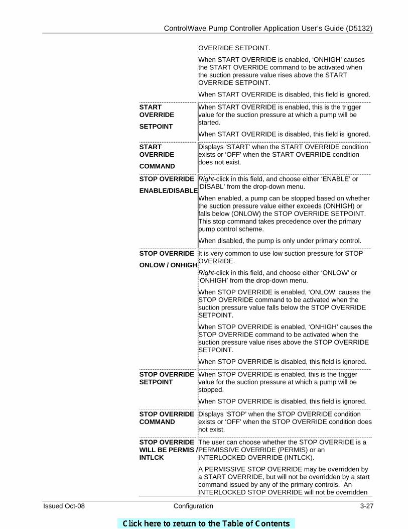
OVERRIDE SETPOINT.
When START OVERRIDE is enabled, ‘ONHIGH’ causes the START OVERRIDE command to be activated when the suction pressure value rises above the START OVERRIDE SETPOINT.
When START OVERRIDE is disabled, this field is ignored.
START OVERRIDE
SETPOINT
When START OVERRIDE is enabled, this is the trigger value for the suction pressure at which a pump will be started.
When START OVERRIDE is disabled, this field is ignored.
START OVERRIDE
COMMAND
Displays ‘START’ when the START OVERRIDE condition exists or ‘OFF’ when the START OVERRIDE condition does not exist.
STOP OVERRIDE
ENABLE/DISABLE
Right-click in this field, and choose either ‘ENABLE’ or ‘DISABL’ from the drop-down menu.
When enabled, a pump can be stopped based on whether the suction pressure value either exceeds (ONHIGH) or falls below (ONLOW) the STOP OVERRIDE SETPOINT. This stop command takes precedence over the primary pump control scheme.
When disabled, the pump is only under primary control.
STOP OVERRIDE
ONLOW / ONHIGH
It is very common to use low suction pressure for STOP OVERRIDE.
Right-click in this field, and choose either ‘ONLOW’ or ‘ONHIGH’ from the drop-down menu.
When STOP OVERRIDE is enabled, ‘ONLOW’ causes the STOP OVERRIDE command to be activated when the suction pressure value falls below the STOP OVERRIDE SETPOINT.
When STOP OVERRIDE is enabled, ‘ONHIGH’ causes the STOP OVERRIDE command to be activated when the suction pressure value rises above the STOP OVERRIDE SETPOINT.
When STOP OVERRIDE is disabled, this field is ignored.
STOP OVERRIDE SETPOINT
When STOP OVERRIDE is enabled, this is the trigger value for the suction pressure at which a pump will be stopped.
When STOP OVERRIDE is disabled, this field is ignored.
STOP OVERRIDE COMMAND
Displays ‘STOP’ when the STOP OVERRIDE condition exists or ‘OFF’ when the STOP OVERRIDE condition does not exist.
STOP OVERRIDE WILL BE PERMIS / INTLCK
The user can choose whether the STOP OVERRIDE is a PERMISSIVE OVERRIDE (PERMIS) or an INTERLOCKED OVERRIDE (INTLCK).
A PERMISSIVE STOP OVERRIDE may be overridden by a START OVERRIDE, but will not be overridden by a start command issued by any of the primary controls. An INTERLOCKED STOP OVERRIDE will not be overridden
ControlWave Pump Controller Application User’s Guide (D5132)
3-28 Configuration Issued Oct-08
by any start command, whether issued by a primary control or an override control.
When finished, click on BACK.
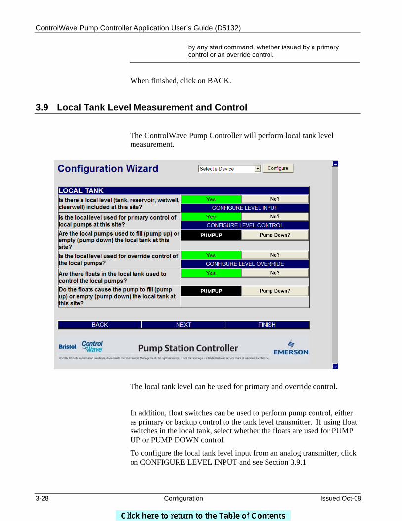
3.9 Local Tank Level Measurement and Control
The ControlWave Pump Controller will perform local tank level measurement.
The local tank level can be used for primary and override control.
In addition, float switches can be used to perform pump control, either as primary or backup control to the tank level transmitter. If using float switches in the local tank, select whether the floats are used for PUMP UP or PUMP DOWN control.
To configure the local tank level input from an analog transmitter, click on CONFIGURE LEVEL INPUT and see Section 3.9.1
ControlWave Pump Controller Application User’s Guide (D5132)
Issued Oct-08 Configuration 3-29
To configure the local tank level for primary pump control, first select whether operating the pumps will fill the tank (PUMP UP control) or operating the pumps will empty the tank (PUMP DOWN control). After selecting PUMP UP or PUMP DOWN control, click on CONFIGURE LEVEL CONTROL and see Section 3.9.2.
To configure the local tank level for override pump control, click on CONFIGURE LEVEL OVERRIDE and see Section 3.9.3.
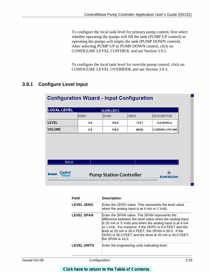
3.9.1 Configure Level Input
Field Description
LEVEL ZERO Enter the ZERO value. This represents the level value when the analog input is at 4 mA or 1 Volt).
LEVEL SPAN Enter the SPAN value. The SPAN represents the difference between the level value when the analog input is 20 mA or 5 Volts and when the analog input is at 4 mA or 1 Volt. For instance, if the ZERO is 0.0 FEET and the level at 20 mA is 35.0 FEET, the SPAN is 35.0. If the ZERO is 35.0 FEET and the level at 20 mA is 45.0 FEET, the SPAN is 10.0.
LEVEL UNITS Enter the engineering units indicating level.
ControlWave Pump Controller Application User’s Guide (D5132)
3-30 Configuration Issued Oct-08
LEVEL DESCRIPTOR
Enter a descriptor for the local level transmitter. This descriptor will be used throughout the rest of the menus to represent local level.
In addition to the level, it is possible in some cases to calculate the volume in the tank. This is only possible when there is a linear relationship between level and volume. In other words, if 1 foot of tank level always equals the same number of gallons in the tank, then volume can be calculated. However, if the tank is non-linear (for instance, a tank shaped like a sphere or a cylinder lying horizontally) volume measurement is not possible.
VOLUME ZERO Enter the ZERO value. This represents the volume value
when the level value is at zero.
VOLUME SPAN Enter the SPAN value. The SPAN represents the difference between the volume value when the level input is at 20 mA or 5 Volts and when the level input is at 4 mA or 1 Volt. For instance, if the ZERO is 0.0 GALLONS and the volume when the level input at 20 mA is 300,000 GALLONS, the SPAN is 300,000.0. If the ZERO is 10,000.0 GALLONS and the volume when the level input is at 20 mA is 50,000 GALLONS, the SPAN is 40,000.0.
VOLUME UNITS Enter the engineering units indicating volume.
VOLUME DESCRIPTOR
The volume descriptor will be generated automatically by appending the word ‘VOLUME’ to the LEVEL DESCRIPTOR. This descriptor will be used throughout the rest of the menus to represent volume of the local tank.
To configure alarm limits, click on ALARM LIMITS. (See Section 3.6 for details.)
When finished, click on BACK.
ControlWave Pump Controller Application User’s Guide (D5132)
Issued Oct-08 Configuration 3-31
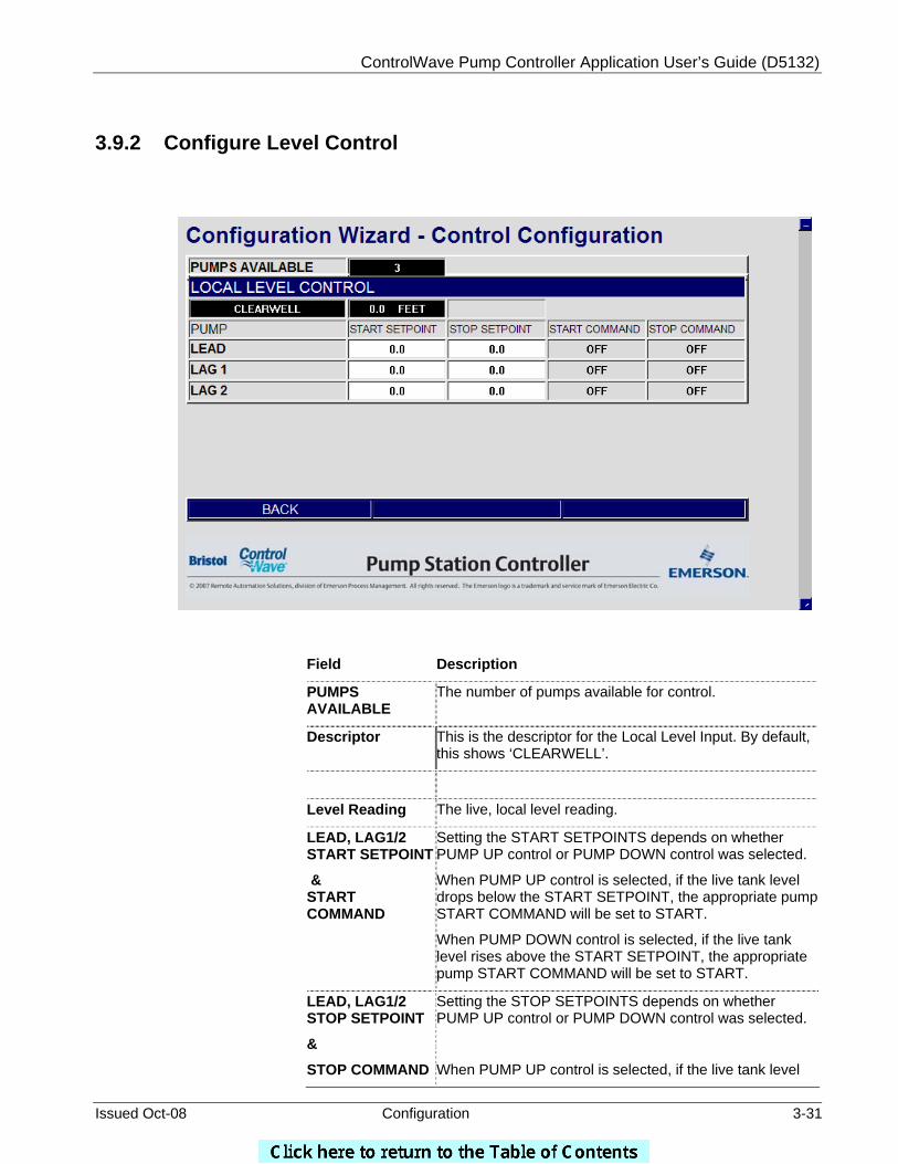
3.9.2 Configure Level Control
Field Description
PUMPS AVAILABLE
The number of pumps available for control.
Descriptor This is the descriptor for the Local Level Input. By default, this shows ‘CLEARWELL’.
Level Reading The live, local level reading.
LEAD, LAG1/2 START SETPOINT
& START COMMAND
Setting the START SETPOINTS depends on whether PUMP UP control or PUMP DOWN control was selected.
When PUMP UP control is selected, if the live tank level drops below the START SETPOINT, the appropriate pump START COMMAND will be set to START.
When PUMP DOWN control is selected, if the live tank level rises above the START SETPOINT, the appropriate pump START COMMAND will be set to START.
LEAD, LAG1/2 STOP SETPOINT
&
STOP COMMAND
Setting the STOP SETPOINTS depends on whether PUMP UP control or PUMP DOWN control was selected.
When PUMP UP control is selected, if the live tank level
ControlWave Pump Controller Application User’s Guide (D5132)
3-32 Configuration Issued Oct-08
rises above the STOP SETPOINT, the appropriate pump STOP COMMAND will be set to STOP.
When PUMP DOWN control is selected, if the live tank level falls below the STOP SETPOINT, the appropriate pump STOP COMMAND will be set to STOP.
When finished, click on BACK.
3.9.3 Configure Level Override
Override Control provides start and stop overrides that would take precedence over primary control. Override Control is used to either start a single pump or stop all pumps.
From here, either or both START OVERRIDE control and STOP OVERRIDE control can be enabled and configured.
Field Description
START OVERRIDE
Right-click in this field, and choose either ‘ENABLE’ or ‘DISABL’ from the drop-down menu.
ControlWave Pump Controller Application User’s Guide (D5132)
Issued Oct-08 Configuration 3-33
ENABLE/DISABL When enabled, a pump can be started based on whether the local tank level value either exceeds (ONHIGH) or falls below (ONLOW) the START OVERRIDE SETPOINT. This start command takes precedence over the primary pump control scheme.
When disabled, the pump is only under primary control.
START OVERRIDE
ONLOW / ONHIGH
Right-click in this field, and choose either ‘ONLOW’ or ‘ONHIGH’ from the drop-down menu.
When START OVERRIDE is enabled, ‘ONLOW’ causes the START OVERRIDE command to be activated when the local tank level value falls below the START OVERRIDE SETPOINT.
When START OVERRIDE is enabled, ‘ONHIGH’ causes the START OVERRIDE command to be activated when the local tank level value rises above the START OVERRIDE SETPOINT.
When START OVERRIDE is disabled, this field is ignored.
START OVERRIDE
SETPOINT
When START OVERRIDE is enabled, this is the trigger value for the local tank level at which a pump will be started.
When START OVERRIDE is disabled, this field is ignored.
START OVERRIDE
COMMAND
Displays ‘START’ when the START OVERRIDE condition exists or ‘OFF’ when the START OVERRIDE condition does not exist.
STOP OVERRIDE
ENABLE/DISABLE
Right-click in this field, and choose either ‘ENABLE’ or ‘DISABL’ from the drop-down menu.
When enabled, a pump can be stopped based on whether the local tank level value either exceeds (ONHIGH) or falls below (ONLOW) the STOP OVERRIDE SETPOINT. This stop command takes precedence over the primary pump control scheme.
When disabled, the pump is only under primary control.
STOP OVERRIDE
ONLOW / ONHIGH
Right-click in this field, and choose either ‘ONLOW’ or ‘ONHIGH’ from the drop-down menu.
When STOP OVERRIDE is enabled, ‘ONLOW’ causes the STOP OVERRIDE command to be activated when the local tank level value falls below the STOP OVERRIDE SETPOINT.
When STOP OVERRIDE is enabled, ‘ONHIGH’ causes the STOP OVERRIDE command to be activated when the local tank level value rises above the STOP OVERRIDE SETPOINT.
When STOP OVERRIDE is disabled, this field is ignored.
STOP OVERRIDE SETPOINT
When STOP OVERRIDE is enabled, this is the trigger value for the local tank level at which a pump will be stopped.
When STOP OVERRIDE is disabled, this field is ignored.
ControlWave Pump Controller Application User’s Guide (D5132)
3-34 Configuration Issued Oct-08
STOP OVERRIDE COMMAND
Displays ‘STOP’ when the STOP OVERRIDE condition exists or ‘OFF’ when the STOP OVERRIDE condition does not exist.
STOP OVERRIDE WILL BE PERMIS / INTLCK
The user can choose whether the STOP OVERRIDE is a PERMISSIVE OVERRIDE (PERMIS) or an INTERLOCKED OVERRIDE (INTLCK).
A PERMISSIVE STOP OVERRIDE may be overridden by a START OVERRIDE, but will not be overridden by a start command issued by any of the primary controls. An INTERLOCKED STOP OVERRIDE will not be overridden by any start command, whether issued by a primary control or an override control.
When finished, click on BACK.
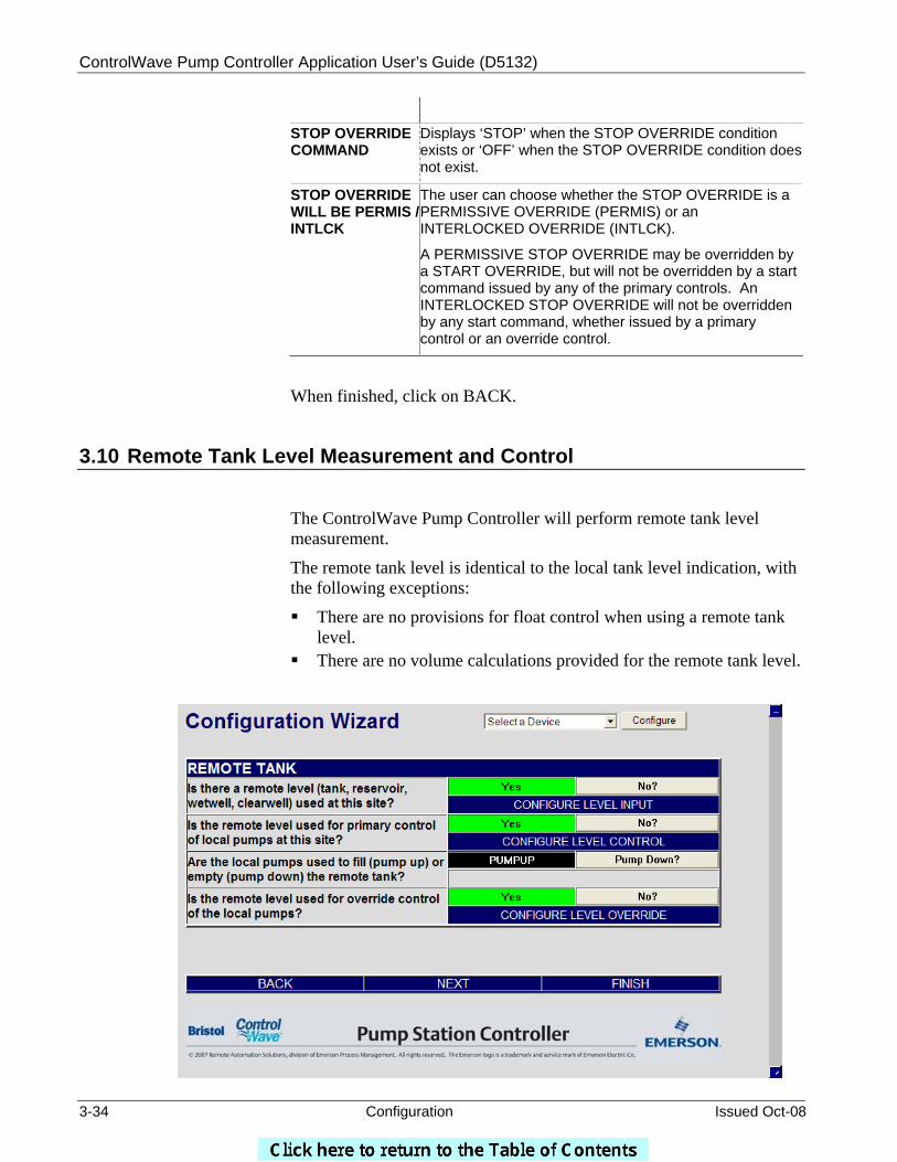
3.10 Remote Tank Level Measurement and Control
The ControlWave Pump Controller will perform remote tank level measurement.
The remote tank level is identical to the local tank level indication, with the following exceptions:
There are no provisions for float control when using a remote tank level.
There are no volume calculations provided for the remote tank level.
ControlWave Pump Controller Application User’s Guide (D5132)
Issued Oct-08 Configuration 3-35
To configure the remote tank level input, click on CONFIGURE LEVEL INPUT and refer to Section 3.10.1.
To configure the remote tank level for primary pump control, first select whether operating the pumps will fill the tank (PUMP UP control) or operating the pumps will empty the tank (PUMP DOWN control). After selecting PUMP UP or PUMP DOWN control, click on CONFIGURE LEVEL CONTROL and refer to Section 3.10.2.
To configure the level override, click on CONFIGURE LEVEL OVERRIDE and refer to Section 3.10.3.
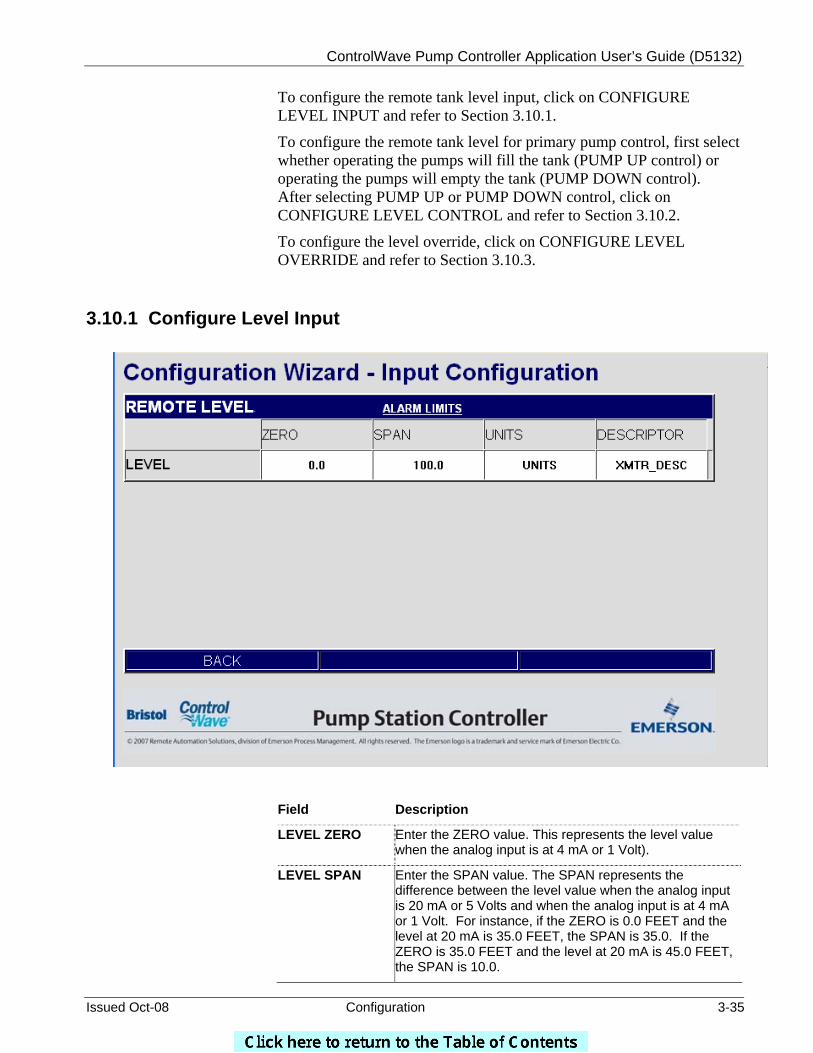
3.10.1 Configure Level Input
Field Description
LEVEL ZERO Enter the ZERO value. This represents the level value when the analog input is at 4 mA or 1 Volt).
LEVEL SPAN Enter the SPAN value. The SPAN represents the difference between the level value when the analog input is 20 mA or 5 Volts and when the analog input is at 4 mA or 1 Volt. For instance, if the ZERO is 0.0 FEET and the level at 20 mA is 35.0 FEET, the SPAN is 35.0. If the ZERO is 35.0 FEET and the level at 20 mA is 45.0 FEET, the SPAN is 10.0.
ControlWave Pump Controller Application User’s Guide (D5132)
3-36 Configuration Issued Oct-08
LEVEL UNITS Enter the engineering units indicating level.
LEVEL DESCRIPTOR
Enter a descriptor for the remote level transmitter. This descriptor will be used throughout the rest of the menus to represent local level.
To configure alarm limits, click on ALARM LIMITS. (See Section 3.6 for details.)
When finished, click on BACK.
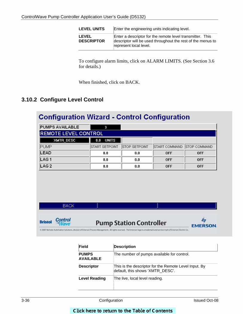
3.10.2 Configure Level Control
Field Description
PUMPS AVAILABLE
The number of pumps available for control.
Descriptor This is the descriptor for the Remote Level Input. By default, this shows ‘XMTR_DESC’.
Level Reading The live, local level reading.
ControlWave Pump Controller Application User’s Guide (D5132)
Issued Oct-08 Configuration 3-37
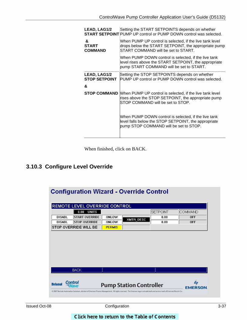
LEAD, LAG1/2 START SETPOINT
& START COMMAND
Setting the START SETPOINTS depends on whether PUMP UP control or PUMP DOWN control was selected.
When PUMP UP control is selected, if the live tank level drops below the START SETPOINT, the appropriate pump START COMMAND will be set to START.
When PUMP DOWN control is selected, if the live tank level rises above the START SETPOINT, the appropriate pump START COMMAND will be set to START.
LEAD, LAG1/2 STOP SETPOINT
&
STOP COMMAND
Setting the STOP SETPOINTS depends on whether PUMP UP control or PUMP DOWN control was selected.
When PUMP UP control is selected, if the live tank level rises above the STOP SETPOINT, the appropriate pump STOP COMMAND will be set to STOP.
When PUMP DOWN control is selected, if the live tank level falls below the STOP SETPOINT, the appropriate pump STOP COMMAND will be set to STOP.
When finished, click on BACK.
3.10.3 Configure Level Override
ControlWave Pump Controller Application User’s Guide (D5132)
3-38 Configuration Issued Oct-08
Field Description
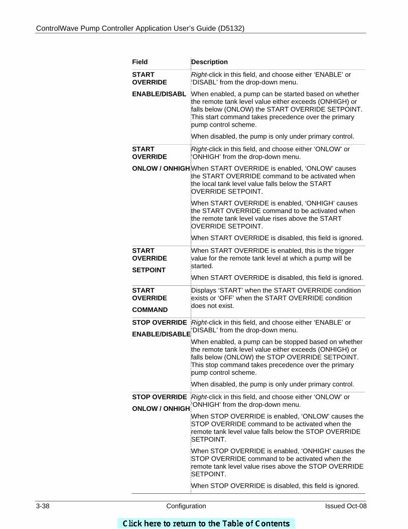
START OVERRIDE
ENABLE/DISABL
Right-click in this field, and choose either ‘ENABLE’ or ‘DISABL’ from the drop-down menu.
When enabled, a pump can be started based on whether the remote tank level value either exceeds (ONHIGH) or falls below (ONLOW) the START OVERRIDE SETPOINT. This start command takes precedence over the primary pump control scheme.
When disabled, the pump is only under primary control.
START OVERRIDE
ONLOW / ONHIGH
Right-click in this field, and choose either ‘ONLOW’ or ‘ONHIGH’ from the drop-down menu.
When START OVERRIDE is enabled, ‘ONLOW’ causes the START OVERRIDE command to be activated when the local tank level value falls below the START OVERRIDE SETPOINT.
When START OVERRIDE is enabled, ‘ONHIGH’ causes the START OVERRIDE command to be activated when the remote tank level value rises above the START OVERRIDE SETPOINT.
When START OVERRIDE is disabled, this field is ignored.
START OVERRIDE
SETPOINT
When START OVERRIDE is enabled, this is the trigger value for the remote tank level at which a pump will be started.
When START OVERRIDE is disabled, this field is ignored.
START OVERRIDE
COMMAND
Displays ‘START’ when the START OVERRIDE condition exists or ‘OFF’ when the START OVERRIDE condition does not exist.
STOP OVERRIDE
ENABLE/DISABLE
Right-click in this field, and choose either ‘ENABLE’ or ‘DISABL’ from the drop-down menu.
When enabled, a pump can be stopped based on whether the remote tank level value either exceeds (ONHIGH) or falls below (ONLOW) the STOP OVERRIDE SETPOINT. This stop command takes precedence over the primary pump control scheme.
When disabled, the pump is only under primary control.
STOP OVERRIDE
ONLOW / ONHIGH
Right-click in this field, and choose either ‘ONLOW’ or ‘ONHIGH’ from the drop-down menu.
When STOP OVERRIDE is enabled, ‘ONLOW’ causes the STOP OVERRIDE command to be activated when the remote tank level value falls below the STOP OVERRIDE SETPOINT.
When STOP OVERRIDE is enabled, ‘ONHIGH’ causes the STOP OVERRIDE command to be activated when the remote tank level value rises above the STOP OVERRIDE SETPOINT.
When STOP OVERRIDE is disabled, this field is ignored.

ControlWave Pump Controller Application User’s Guide (D5132)
Issued Oct-08 Configuration 3-39
STOP OVERRIDE SETPOINT
When STOP OVERRIDE is enabled, this is the trigger value for the remote tank level at which a pump will be stopped.
When STOP OVERRIDE is disabled, this field is ignored.
STOP OVERRIDE COMMAND
Displays ‘STOP’ when the STOP OVERRIDE condition exists or ‘OFF’ when the STOP OVERRIDE condition does not exist.
STOP OVERRIDE WILL BE PERMIS / INTLCK
The user can choose whether the STOP OVERRIDE is a PERMISSIVE OVERRIDE (PERMIS) or an INTERLOCKED OVERRIDE (INTLCK).
A PERMISSIVE STOP OVERRIDE may be overridden by a START OVERRIDE, but will not be overridden by a start command issued by any of the primary controls. An INTERLOCKED STOP OVERRIDE will not be overridden by any start command, whether issued by a primary control or an override control.
When finished, click on BACK.
ControlWave Pump Controller Application User’s Guide (D5132)
3-40 Configuration Issued Oct-08
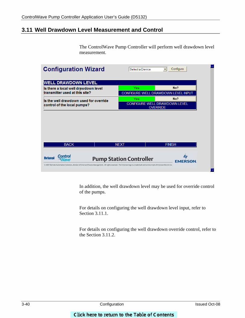
3.11 Well Drawdown Level Measurement and Control
The ControlWave Pump Controller will perform well drawdown level measurement.
:
In addition, the well drawdown level may be used for override control of the pumps.
For details on configuring the well drawdown level input, refer to Section 3.11.1.
For details on configuring the well drawdown override control, refer to the Section 3.11.2.
ControlWave Pump Controller Application User’s Guide (D5132)
Issued Oct-08 Configuration 3-41
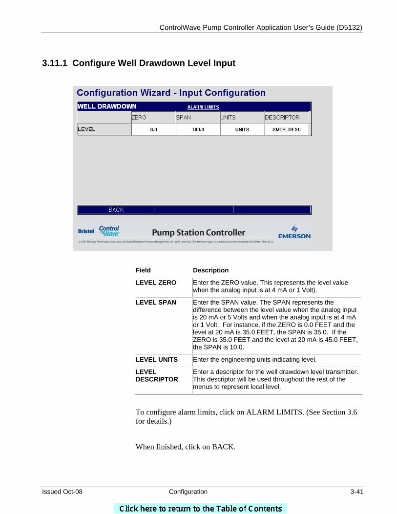
3.11.1 Configure Well Drawdown Level Input
Field Description
LEVEL ZERO Enter the ZERO value. This represents the level value when the analog input is at 4 mA or 1 Volt).
LEVEL SPAN Enter the SPAN value. The SPAN represents the difference between the level value when the analog input is 20 mA or 5 Volts and when the analog input is at 4 mA or 1 Volt. For instance, if the ZERO is 0.0 FEET and the level at 20 mA is 35.0 FEET, the SPAN is 35.0. If the ZERO is 35.0 FEET and the level at 20 mA is 45.0 FEET, the SPAN is 10.0.
LEVEL UNITS Enter the engineering units indicating level.
LEVEL DESCRIPTOR
Enter a descriptor for the well drawdown level transmitter. This descriptor will be used throughout the rest of the menus to represent local level.
To configure alarm limits, click on ALARM LIMITS. (See Section 3.6 for details.)
When finished, click on BACK.
ControlWave Pump Controller Application User’s Guide (D5132)
3-42 Configuration Issued Oct-08
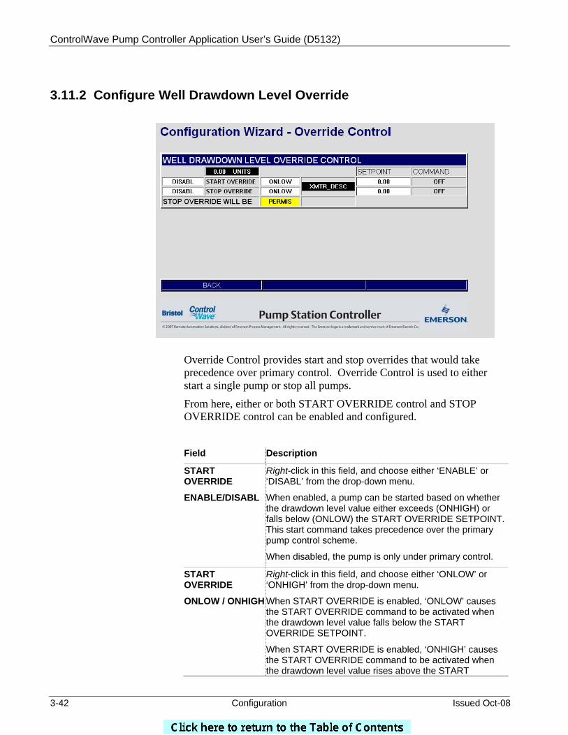
3.11.2 Configure Well Drawdown Level Override
Override Control provides start and stop overrides that would take precedence over primary control. Override Control is used to either start a single pump or stop all pumps.
From here, either or both START OVERRIDE control and STOP OVERRIDE control can be enabled and configured.
Field Description
START OVERRIDE
ENABLE/DISABL
Right-click in this field, and choose either ‘ENABLE’ or ‘DISABL’ from the drop-down menu.
When enabled, a pump can be started based on whether the drawdown level value either exceeds (ONHIGH) or falls below (ONLOW) the START OVERRIDE SETPOINT. This start command takes precedence over the primary pump control scheme.
When disabled, the pump is only under primary control.
START OVERRIDE
ONLOW / ONHIGH
Right-click in this field, and choose either ‘ONLOW’ or ‘ONHIGH’ from the drop-down menu.
When START OVERRIDE is enabled, ‘ONLOW’ causes the START OVERRIDE command to be activated when the drawdown level value falls below the START OVERRIDE SETPOINT.
When START OVERRIDE is enabled, ‘ONHIGH’ causes the START OVERRIDE command to be activated when the drawdown level value rises above the START
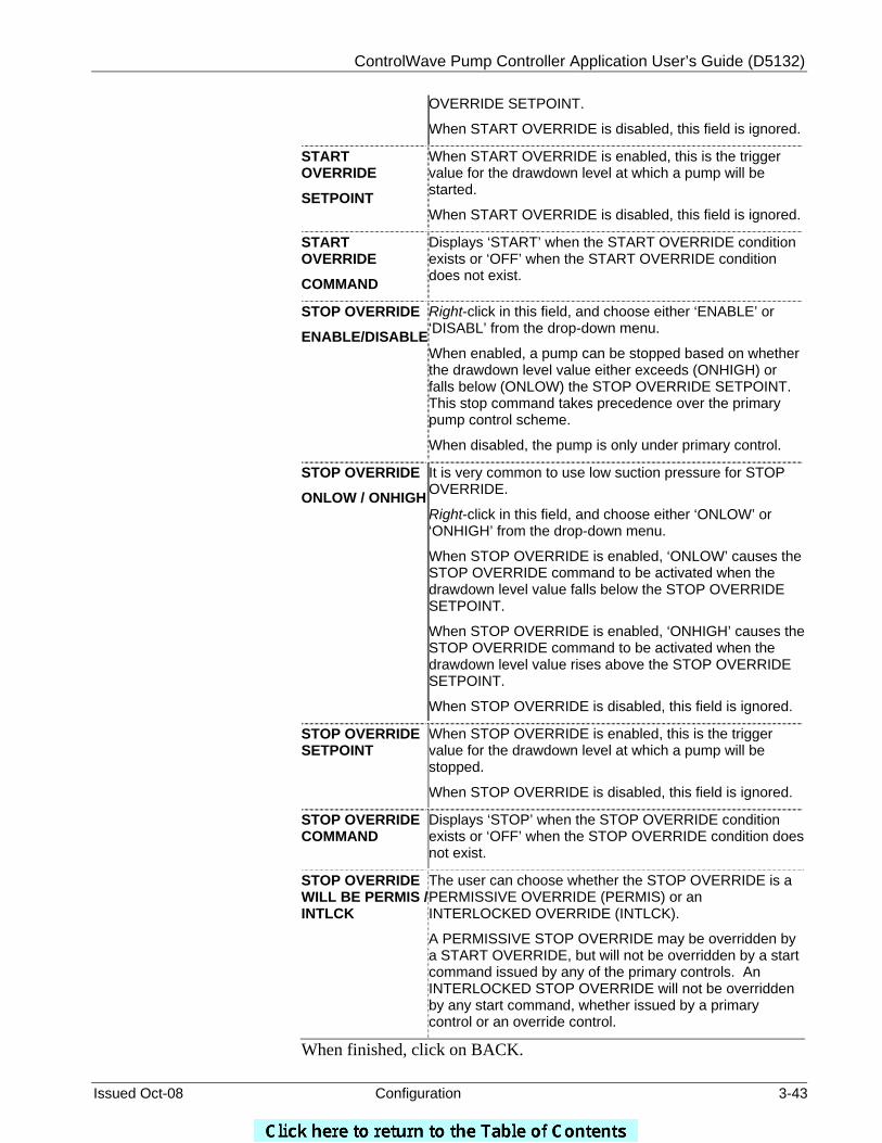
ControlWave Pump Controller Application User’s Guide (D5132)
Issued Oct-08 Configuration 3-43
OVERRIDE SETPOINT.
When START OVERRIDE is disabled, this field is ignored.
START OVERRIDE
SETPOINT
When START OVERRIDE is enabled, this is the trigger value for the drawdown level at which a pump will be started.
When START OVERRIDE is disabled, this field is ignored.
START OVERRIDE
COMMAND
Displays ‘START’ when the START OVERRIDE condition exists or ‘OFF’ when the START OVERRIDE condition does not exist.
STOP OVERRIDE
ENABLE/DISABLE
Right-click in this field, and choose either ‘ENABLE’ or ‘DISABL’ from the drop-down menu.
When enabled, a pump can be stopped based on whether the drawdown level value either exceeds (ONHIGH) or falls below (ONLOW) the STOP OVERRIDE SETPOINT. This stop command takes precedence over the primary pump control scheme.
When disabled, the pump is only under primary control.
STOP OVERRIDE
ONLOW / ONHIGH
It is very common to use low suction pressure for STOP OVERRIDE.
Right-click in this field, and choose either ‘ONLOW’ or ‘ONHIGH’ from the drop-down menu.
When STOP OVERRIDE is enabled, ‘ONLOW’ causes the STOP OVERRIDE command to be activated when the drawdown level value falls below the STOP OVERRIDE SETPOINT.
When STOP OVERRIDE is enabled, ‘ONHIGH’ causes the STOP OVERRIDE command to be activated when the drawdown level value rises above the STOP OVERRIDE SETPOINT.
When STOP OVERRIDE is disabled, this field is ignored.
STOP OVERRIDE SETPOINT
When STOP OVERRIDE is enabled, this is the trigger value for the drawdown level at which a pump will be stopped.
When STOP OVERRIDE is disabled, this field is ignored.
STOP OVERRIDE COMMAND
Displays ‘STOP’ when the STOP OVERRIDE condition exists or ‘OFF’ when the STOP OVERRIDE condition does not exist.
STOP OVERRIDE WILL BE PERMIS / INTLCK
The user can choose whether the STOP OVERRIDE is a PERMISSIVE OVERRIDE (PERMIS) or an INTERLOCKED OVERRIDE (INTLCK).
A PERMISSIVE STOP OVERRIDE may be overridden by a START OVERRIDE, but will not be overridden by a start command issued by any of the primary controls. An INTERLOCKED STOP OVERRIDE will not be overridden by any start command, whether issued by a primary control or an override control.
When finished, click on BACK.
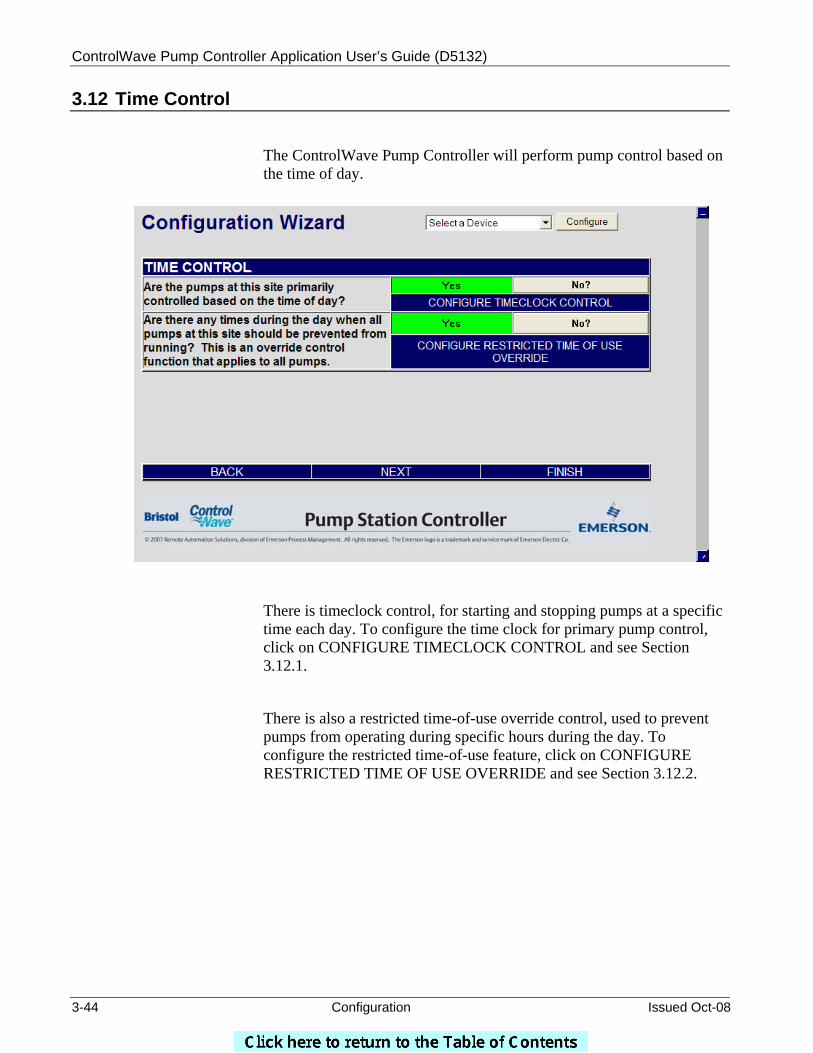
ControlWave Pump Controller Application User’s Guide (D5132)
3-44 Configuration Issued Oct-08
3.12 Time Control
The ControlWave Pump Controller will perform pump control based on the time of day.
There is timeclock control, for starting and stopping pumps at a specific time each day. To configure the time clock for primary pump control, click on CONFIGURE TIMECLOCK CONTROL and see Section 3.12.1.
There is also a restricted time-of-use override control, used to prevent pumps from operating during specific hours during the day. To configure the restricted time-of-use feature, click on CONFIGURE RESTRICTED TIME OF USE OVERRIDE and see Section 3.12.2.
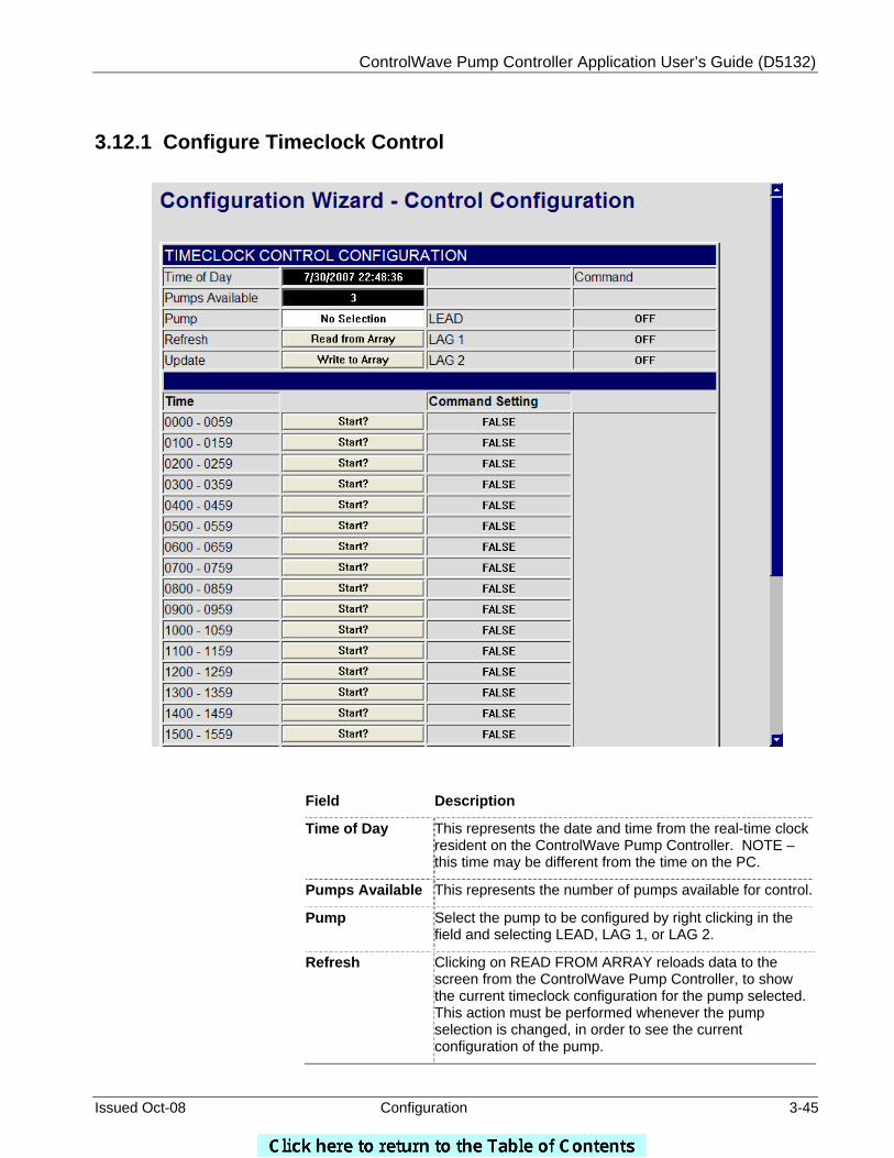
ControlWave Pump Controller Application User’s Guide (D5132)
Issued Oct-08 Configuration 3-45
3.12.1 Configure Timeclock Control
Field Description
Time of Day
This represents the date and time from the real-time clock resident on the ControlWave Pump Controller. NOTE – this time may be different from the time on the PC.
Pumps Available This represents the number of pumps available for control.
Pump Select the pump to be configured by right clicking in the field and selecting LEAD, LAG 1, or LAG 2.
Refresh
Clicking on READ FROM ARRAY reloads data to the screen from the ControlWave Pump Controller, to show the current timeclock configuration for the pump selected. This action must be performed whenever the pump selection is changed, in order to see the current configuration of the pump.

ControlWave Pump Controller Application User’s Guide (D5132)
3-46 Configuration Issued Oct-08
Update
Clicking on WRITE TO ARRAY will download the current timeclock settings from the screen to the configuration for the selected pump.
Lead/Lag1/Lag2
Command
These fields represent the current state of the START command being issued by the timeclock control for each of the pumps.
NOTE – When the timeclock START command transitions from START to OFF, a STOP command is issued for five (5) seconds. This will stop the appropriate pump, and this pump will not be restarted until another start command is issued by the program. The new start command may come from any source (discharge pressure, tank level, etc.)
Configuring the Timeclock:
To configure the timeclock, follow these steps:
1. Select the pump to be configured by right clicking on the PUMP field and selecting LEAD, LAG 1 or LAG 2 (as appropriate).
2. Click on REFRESH. This will allow the current settings for the selected pump to be reviewed before making changes.
3. To configure a pump to run during a particular hour, click on the START? button for that hour. (If the specific hour is not visible, use the scroll bar to bring it into view.). Once you have clicked on the appropriate START? Button, the field to the right should change from FALSE to START. If the field already indicates START, the pump is configured to run during that hour.
4. In order to set the timeclock control command for a specific hour to FALSE, click on the OFF? button. The field to the right should change from START to FALSE.
5. When the configuration settings are complete, click on the UPDATE button. The configuration for the pump selected will now be saved to the ControlWave Pump Controller.
Note: If the COMMAND SETTING field for a particular hour is false, other control parameters (tank level, discharge pressure, etc.) can cause the pump to start. The timeclock is not used to prevent a pump from running. To prevent a pump from being started during a particular time of day, the RESTRICTED TIME OF USE function must be used.
When finished, click on BACK.
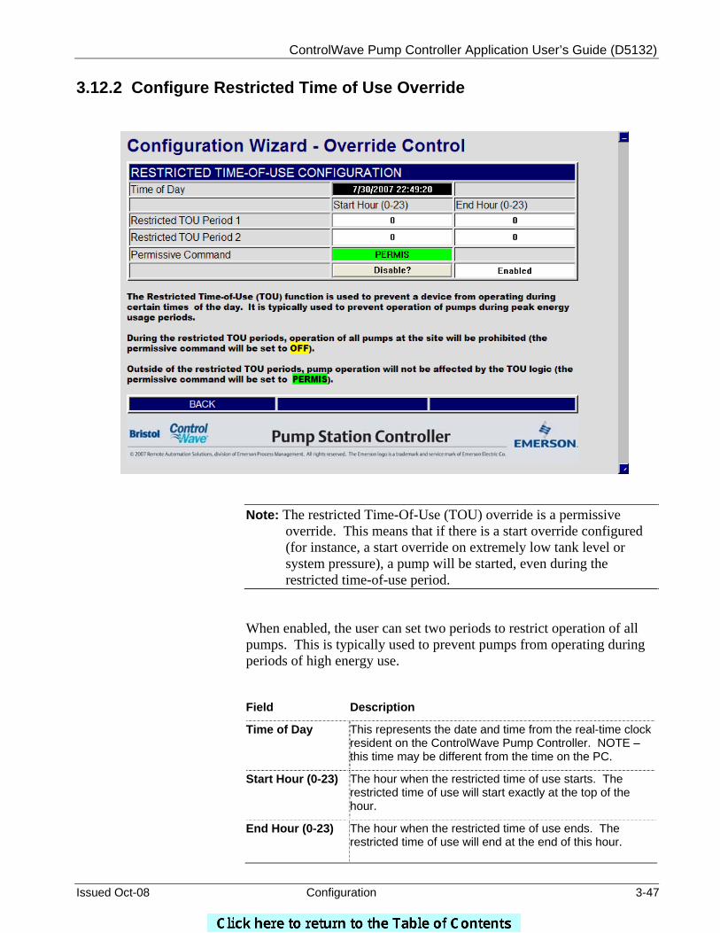
ControlWave Pump Controller Application User’s Guide (D5132)
Issued Oct-08 Configuration 3-47
3.12.2 Configure Restricted Time of Use Override
Note: The restricted Time-Of-Use (TOU) override is a permissive override. This means that if there is a start override configured (for instance, a start override on extremely low tank level or system pressure), a pump will be started, even during the restricted time-of-use period.
When enabled, the user can set two periods to restrict operation of all pumps. This is typically used to prevent pumps from operating during periods of high energy use.
Field Description
Time of Day
This represents the date and time from the real-time clock resident on the ControlWave Pump Controller. NOTE – this time may be different from the time on the PC.
Start Hour (0-23)
The hour when the restricted time of use starts. The restricted time of use will start exactly at the top of the hour.
End Hour (0-23)
The hour when the restricted time of use ends. The restricted time of use will end at the end of this hour.
ControlWave Pump Controller Application User’s Guide (D5132)
3-48 Configuration Issued Oct-08
Permissive Command
If the time-of-use control is enabled, then during the restricted time-of-use period, the permissive command will be set to OFF. This will prevent the pumps from operating, unless a start override command is issued.
If the time-of-use control is disabled, or if the time-of-use control is enabled and the time of day is outside the restricted time-of-use period, the permissive command will be set to PERMIS. This will allow the pumps to be started by any primary control or override control.
Disable ?/
Enable ?
Use this button to disable or enable the restricted time-of-use control.
When finished, click on BACK.
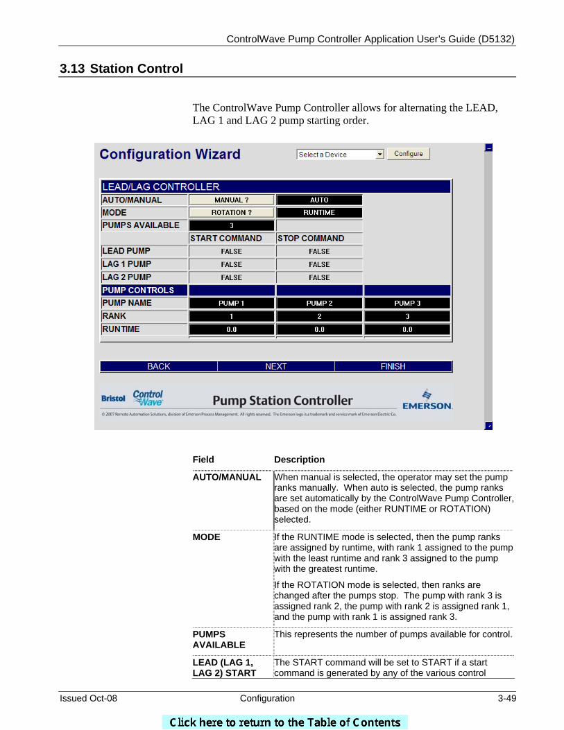
ControlWave Pump Controller Application User’s Guide (D5132)
Issued Oct-08 Configuration 3-49
3.13 Station Control
The ControlWave Pump Controller allows for alternating the LEAD, LAG 1 and LAG 2 pump starting order.
Field Description
AUTO/MANUAL
When manual is selected, the operator may set the pump ranks manually. When auto is selected, the pump ranks are set automatically by the ControlWave Pump Controller, based on the mode (either RUNTIME or ROTATION) selected.
MODE
If the RUNTIME mode is selected, then the pump ranks are assigned by runtime, with rank 1 assigned to the pump with the least runtime and rank 3 assigned to the pump with the greatest runtime.
If the ROTATION mode is selected, then ranks are changed after the pumps stop. The pump with rank 3 is assigned rank 2, the pump with rank 2 is assigned rank 1, and the pump with rank 1 is assigned rank 3.
PUMPS AVAILABLE
This represents the number of pumps available for control.
LEAD (LAG 1, LAG 2) START
The START command will be set to START if a start command is generated by any of the various control
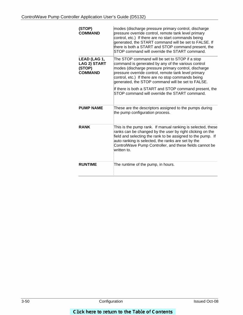
ControlWave Pump Controller Application User’s Guide (D5132)
3-50 Configuration Issued Oct-08
(STOP) COMMAND
modes (discharge pressure primary control, discharge pressure override control, remote tank level primary control, etc.) If there are no start commands being generated, the START command will be set to FALSE. If there is both a START and STOP command present, the STOP command will override the START command.
LEAD (LAG 1, LAG 2) START (STOP) COMMAND
The STOP command will be set to STOP if a stop command is generated by any of the various control modes (discharge pressure primary control, discharge pressure override control, remote tank level primary control, etc.) If there are no stop commands being generated, the STOP command will be set to FALSE.
If there is both a START and STOP command present, the STOP command will override the START command.
PUMP NAME
These are the descriptors assigned to the pumps during the pump configuration process.
RANK This is the pump rank. If manual ranking is selected, these ranks can be changed by the user by right clicking on the field and selecting the rank to be assigned to the pump. If auto ranking is selected, the ranks are set by the ControlWave Pump Controller, and these fields cannot be written to.
RUNTIME The runtime of the pump, in hours.
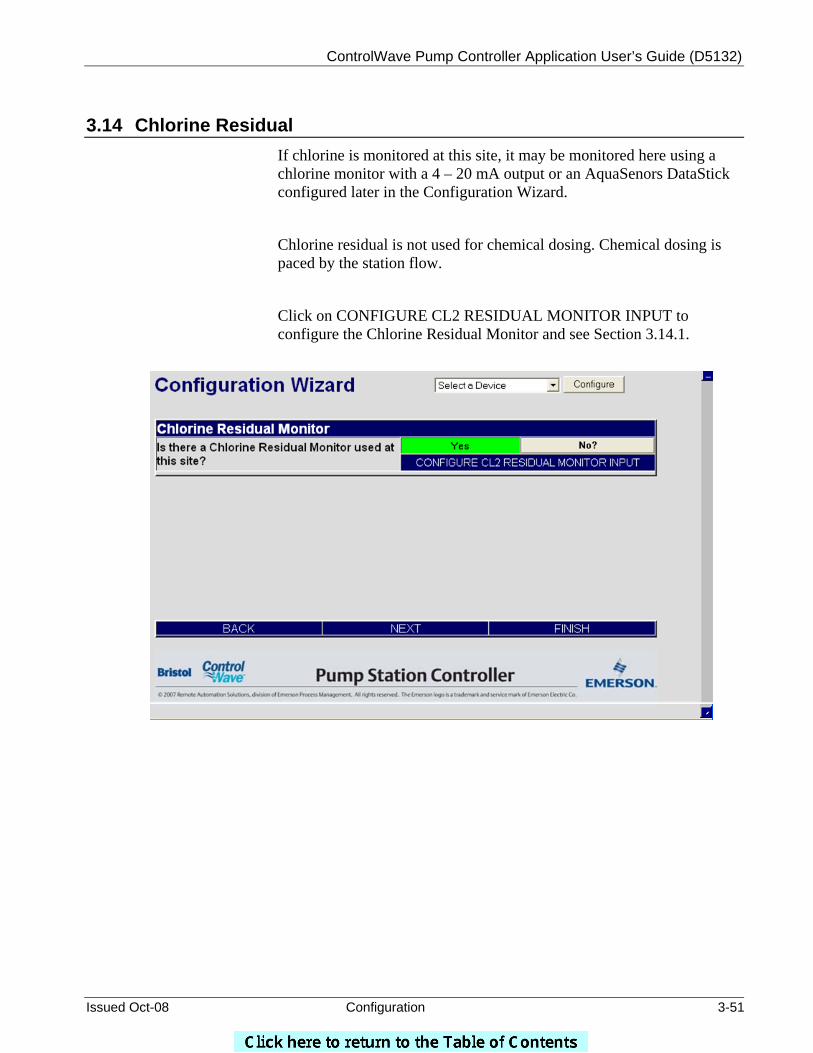
ControlWave Pump Controller Application User’s Guide (D5132)
Issued Oct-08 Configuration 3-51
3.14 Chlorine Residual If chlorine is monitored at this site, it may be monitored here using a chlorine monitor with a 4 – 20 mA output or an AquaSenors DataStick configured later in the Configuration Wizard.
Chlorine residual is not used for chemical dosing. Chemical dosing is paced by the station flow.
Click on CONFIGURE CL2 RESIDUAL MONITOR INPUT to configure the Chlorine Residual Monitor and see Section 3.14.1.
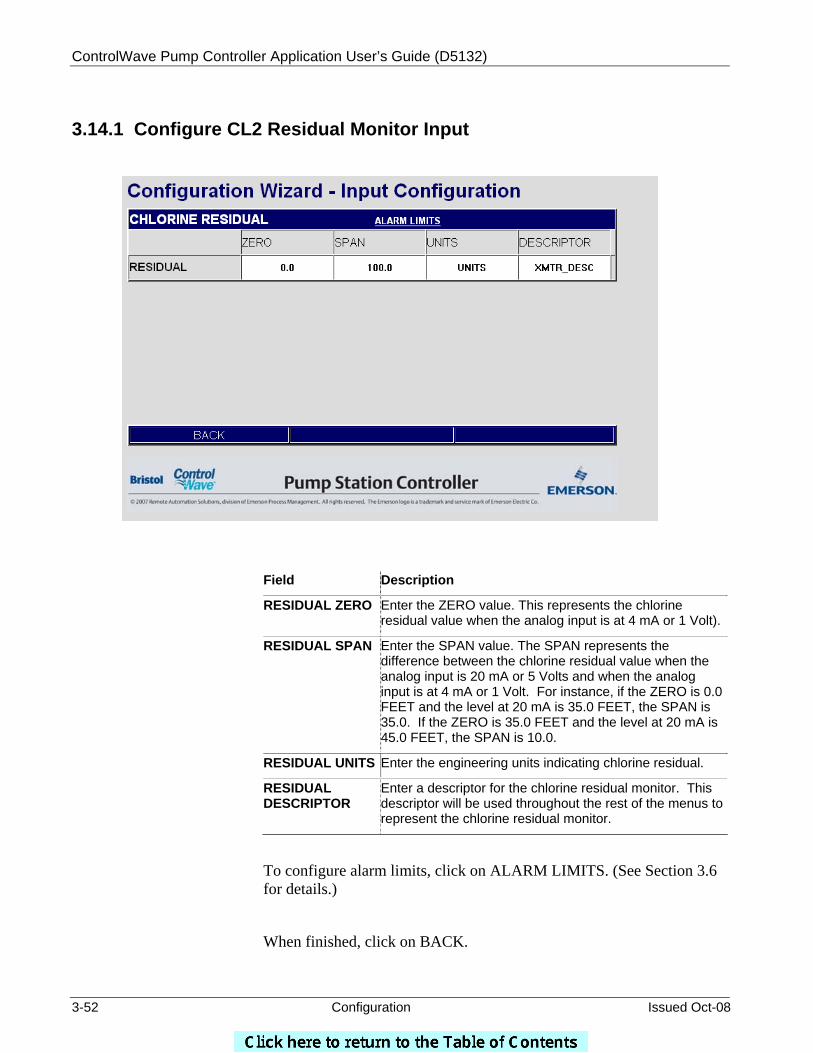
ControlWave Pump Controller Application User’s Guide (D5132)
3-52 Configuration Issued Oct-08
3.14.1 Configure CL2 Residual Monitor Input
Field Description
RESIDUAL ZERO Enter the ZERO value. This represents the chlorine residual value when the analog input is at 4 mA or 1 Volt).
RESIDUAL SPAN Enter the SPAN value. The SPAN represents the difference between the chlorine residual value when the analog input is 20 mA or 5 Volts and when the analog input is at 4 mA or 1 Volt. For instance, if the ZERO is 0.0 FEET and the level at 20 mA is 35.0 FEET, the SPAN is 35.0. If the ZERO is 35.0 FEET and the level at 20 mA is 45.0 FEET, the SPAN is 10.0.
RESIDUAL UNITS Enter the engineering units indicating chlorine residual.
RESIDUAL DESCRIPTOR
Enter a descriptor for the chlorine residual monitor. This descriptor will be used throughout the rest of the menus to represent the chlorine residual monitor.
To configure alarm limits, click on ALARM LIMITS. (See Section 3.6 for details.)
When finished, click on BACK.
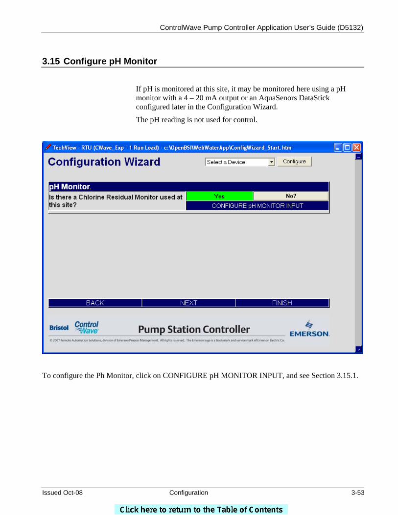
ControlWave Pump Controller Application User’s Guide (D5132)
Issued Oct-08 Configuration 3-53
3.15 Configure pH Monitor
If pH is monitored at this site, it may be monitored here using a pH monitor with a 4 – 20 mA output or an AquaSenors DataStick configured later in the Configuration Wizard.
The pH reading is not used for control.
To configure the Ph Monitor, click on CONFIGURE pH MONITOR INPUT, and see Section 3.15.1.
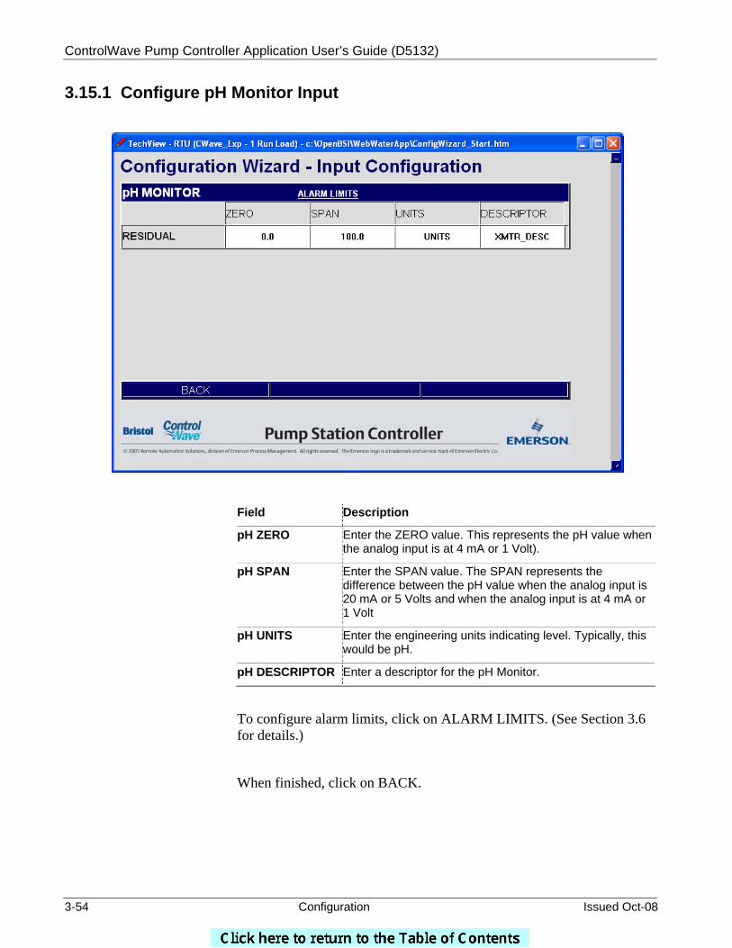
ControlWave Pump Controller Application User’s Guide (D5132)
3-54 Configuration Issued Oct-08
3.15.1 Configure pH Monitor Input
Field Description
pH ZERO Enter the ZERO value. This represents the pH value when the analog input is at 4 mA or 1 Volt).
pH SPAN Enter the SPAN value. The SPAN represents the difference between the pH value when the analog input is 20 mA or 5 Volts and when the analog input is at 4 mA or 1 Volt
pH UNITS Enter the engineering units indicating level. Typically, this would be pH.
pH DESCRIPTOR Enter a descriptor for the pH Monitor.
To configure alarm limits, click on ALARM LIMITS. (See Section 3.6 for details.)
When finished, click on BACK.
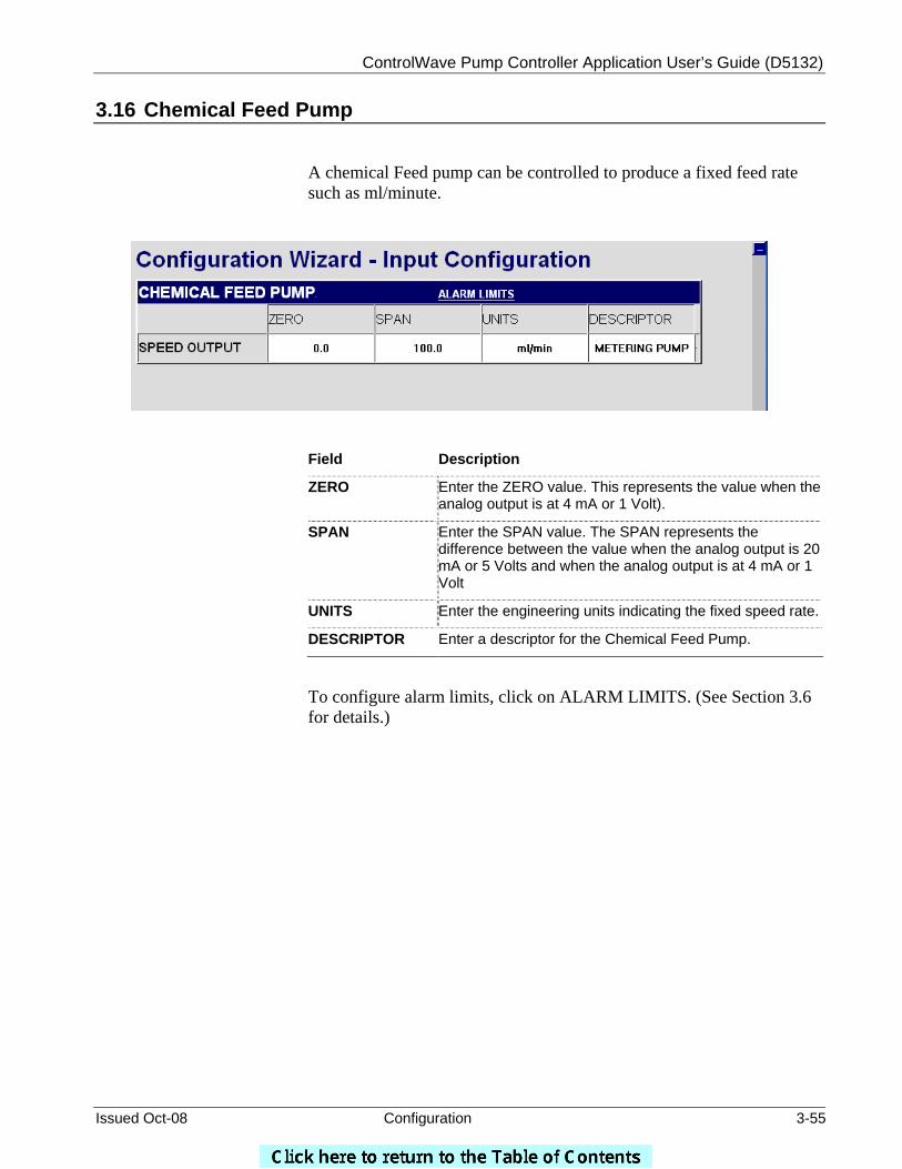
ControlWave Pump Controller Application User’s Guide (D5132)
Issued Oct-08 Configuration 3-55
3.16 Chemical Feed Pump
A chemical Feed pump can be controlled to produce a fixed feed rate such as ml/minute.
Field Description
ZERO Enter the ZERO value. This represents the value when the analog output is at 4 mA or 1 Volt).
SPAN Enter the SPAN value. The SPAN represents the difference between the value when the analog output is 20 mA or 5 Volts and when the analog output is at 4 mA or 1 Volt
UNITS Enter the engineering units indicating the fixed speed rate.
DESCRIPTOR Enter a descriptor for the Chemical Feed Pump.
To configure alarm limits, click on ALARM LIMITS. (See Section 3.6 for details.)
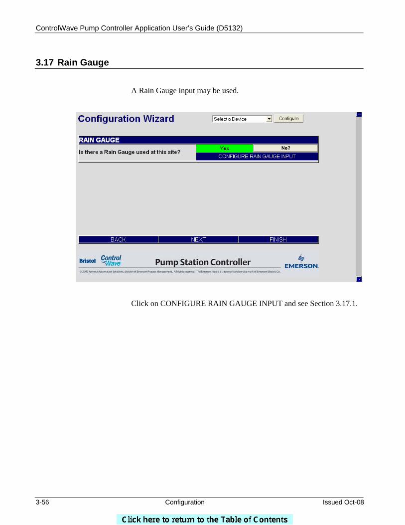
ControlWave Pump Controller Application User’s Guide (D5132)
3-56 Configuration Issued Oct-08
3.17 Rain Gauge
A Rain Gauge input may be used.
Click on CONFIGURE RAIN GAUGE INPUT and see Section 3.17.1.
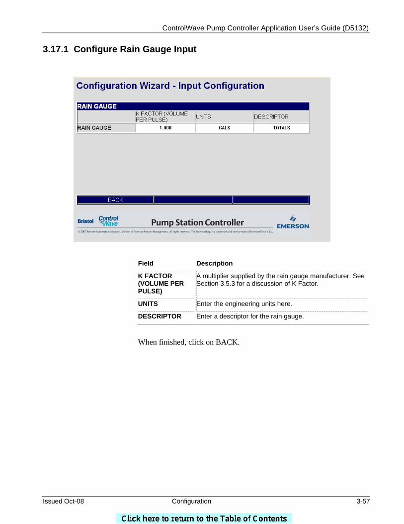
ControlWave Pump Controller Application User’s Guide (D5132)
Issued Oct-08 Configuration 3-57
3.17.1 Configure Rain Gauge Input
Field Description
K FACTOR (VOLUME PER PULSE)
A multiplier supplied by the rain gauge manufacturer. See Section 3.5.3 for a discussion of K Factor.
UNITS Enter the engineering units here.
DESCRIPTOR Enter a descriptor for the rain gauge.
When finished, click on BACK.
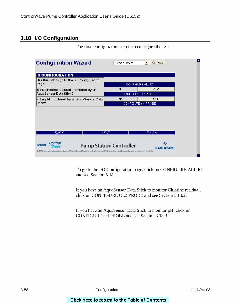
ControlWave Pump Controller Application User’s Guide (D5132)
3-58 Configuration Issued Oct-08
3.18 I/O Configuration
The final configuration step is to configure the I/O.
To go to the I/O Configuration page, click on CONFIGURE ALL IO and see Section 3.18.1.
If you have an AquaSensor Data Stick to monitor Chlorine residual, click on CONFIGURE CL2 PROBE and see Section 3.18.2.
If you have an AquaSensor Data Stick to monitor pH, click on CONFIGURE pH PROBE and see Section 3.18.3.

ControlWave Pump Controller Application User’s Guide (D5132)
Issued Oct-08 Configuration 3-59
3.18.1 Configure All I/O
A warning appears as a reminder to ensure that the system is in a safe mode prior to making I/O configuration changes. Click on [OK] to proceed.
ControlWave Pump Controller Application User’s Guide (D5132)
3-60 Configuration Issued Oct-08
MAX I/O This area provides information regarding the amount of I/O available considering the ControlWave model you are using. Field Description
DI, DO, AI, AO, HSC
Based on the specified type of ControlWave model you are using, this indicates the maximum number of I/O points of each type: DI (Discrete Input), DO (Discrete Output), AI (Analog Input), AO (Analog Output), or HSC (High Speed Counter).
NOTE: For mixed I/O boards, the Pump Controller Application has no way to detect which I/O is actually available, since, some I/O is configured only by jumpers on the hardware. As a result, these fields only display the maximum I/O that might be present, based on the board type.
PUMPS There are up to six inputs and two outputs that may be connected for each pump. The physical I/O available in the ControlWave model, and the indicator signals available from the particular model of pump, determine the number points you may assign to these inputs or outputs. Always On and Always Off are selectable when there is no connection to a physical input or output.
Field Description
DEVICE Identifies the pump to which the I/O is connected.
RUN STATUS
DI POINT
This DI point indicates whether or not the pump is actually running. Select the appropriate DI that reports this status. If you don’t have a DI that performs this function, choose either ‘Always Off’, or ‘Always On’, as appropriate to your application.
REMOTE DI POINT
If the pump is wired to a two-wire REMOTE-LOCAL switch, or a three-wire HAND-OFF-AUTO switch, specify the DI associated with the REMOTE or AUTO function. If you don’t have a DI that performs this function, choose either ‘Always Off’, or ‘Always On’, as appropriate to your application.
LOCAL DI POINT If the pump is wired to a two-wire REMOTE-LOCAL switch, specify the DI associated with the LOCAL function. If you don’t have a DI that performs this function, choose either ‘Always Off’, or ‘Always On’, as appropriate to your application.
TROUBLE DI POINT
If the pump has a trouble-indicator that can be wired to a DI, specify the DI associated with that function here. If you don’t have a DI that performs this function, choose either ‘Always Off’, or ‘Always On’, as appropriate to your application.
ControlWave Pump Controller Application User’s Guide (D5132)
Issued Oct-08 Configuration 3-61
POWER FAIL DI POINT
If the pump has a power fail-indicator that can be wired to a DI, specify the DI associated with that function here. If you don’t have a DI that performs this function, choose either ‘Always Off’, or ‘Always On’, as appropriate to your application.
TAGOUT DI POINT
If the pump has a ‘Tagout’ indicator, that means that the pump is out-of-service for maintenance or repair, specify the DI associated with that function here. If you don’t have a DI that performs this function, choose either ‘Always Off’, or ‘Always On’, as appropriate to your application. NOTE: All start commands for this pump via the Pump Controller Application are stopped if this DI is ON.
START DO POINT Specify the DO used to start the pump here. If you don’t have a DO that performs this function, choose either ‘Always Off’, or ‘Always On’, as appropriate to your application.
STOP DO POINT Specify the DO used to stop the pump here. If you don’t have a DO that performs this function, choose either ‘Always Off’, or ‘Always On’, as appropriate to your application.
TANK FLOATS Discrete inputs not assigned to the pumps are available for tank float inputs or building security. Field Description
DEVICE Identifies the tank to which the I/O is connected.
HI HI FLOAT DI POINT
This DI point is used to indicate that the tank float level has exceeded the HI HI alarm level. Specify the DI associated with this level, or, if you don’t have a DI for this function available, specify either ‘Always Off’ or ‘Always On’ as appropriate to your application.
HI FLOAT DI POINT
This DI point is used to indicate that the tank float level has exceeded the HI alarm level. Specify the DI associated with this level, or, if you don’t have a DI for this function available, specify either ‘Always Off’ or ‘Always On’ as appropriate to your application.
LO FLOAT DI POINT
This DI point is used to indicate that the tank float level has reach the LO alarm level. Specify the DI associated with this level, or, if you don’t have a DI for this function available, specify either ‘Always Off’ or ‘Always On’ as appropriate to your application.
LO LO FLOAT DI POINT
This DI point is used to indicate that the tank float level has reach the HI HI alarm level. Specify the DI associated with this level, or, if you don’t have a DI for this function available, specify either ‘Always Off’ or ‘Always On’ as appropriate to your application.
ControlWave Pump Controller Application User’s Guide (D5132)
3-62 Configuration Issued Oct-08
BUILDING SECURITY Discrete inputs not assigned to the pumps are available for tank float inputs and building security. Field Description
DEVICE Identifies the building security device.
INTRUSION DI This DI point indicates intrusion detection. Select the appropriate DI that reports this status. If you don’t have a DI that performs this function, choose either ‘Always Off’, or ‘Always On’, as appropriate to your application.
INTRUSION DISABLE DI
This DI point disables the intrusion detection DI. If you don’t have a DI that performs this function, choose either ‘Always Off’, or ‘Always On’, as appropriate to your application.
ANALOG INPUTS / ANALOG OUTPUTS Analog inputs or outputs may be assigned to the AI POINT or AO POINT fields, respectively Field Description
DEVICE Identifies the device associated with the input or output.
VALUE The current value of the AI or AO. If the input or output has no physical connection, the VALUE will be the ZERO value.
AI POINT / AO POINT
Select the appropriate AI or AO for the DEVICE. A Zero in the cell indicates that there is no connection to a physical input or output; in this case the value in the VALUE field will be the same value entered in the ZERO field.
ZERO Enter the ZERO value. This represents the value when the analog input (or output) is at 4 mA or 1 Volt).
SPAN Enter the SPAN value. The SPAN represents the difference between the value when the analog input (or output) is 20 mA or 5 Volts and when it is at 4 mA or 1 Volt.
UNITS Enter the engineering units here.
DESCRIPTOR Enter a descriptor here. This descriptor will be used throughout the rest of the menus.
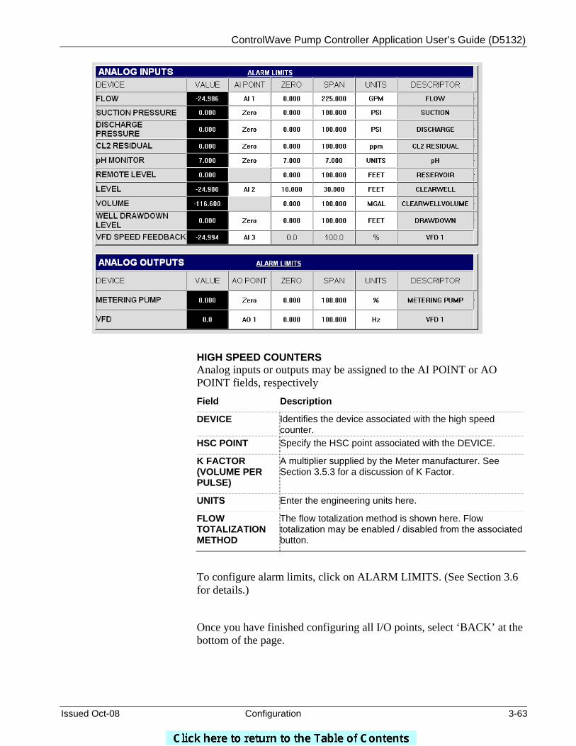
ControlWave Pump Controller Application User’s Guide (D5132)
Issued Oct-08 Configuration 3-63
HIGH SPEED COUNTERS Analog inputs or outputs may be assigned to the AI POINT or AO POINT fields, respectively Field Description
DEVICE Identifies the device associated with the high speed counter.
HSC POINT Specify the HSC point associated with the DEVICE.
K FACTOR (VOLUME PER PULSE)
A multiplier supplied by the Meter manufacturer. See Section 3.5.3 for a discussion of K Factor.
UNITS Enter the engineering units here.
FLOW TOTALIZATION METHOD
The flow totalization method is shown here. Flow totalization may be enabled / disabled from the associated button.
To configure alarm limits, click on ALARM LIMITS. (See Section 3.6 for details.)
Once you have finished configuring all I/O points, select ‘BACK’ at the bottom of the page.
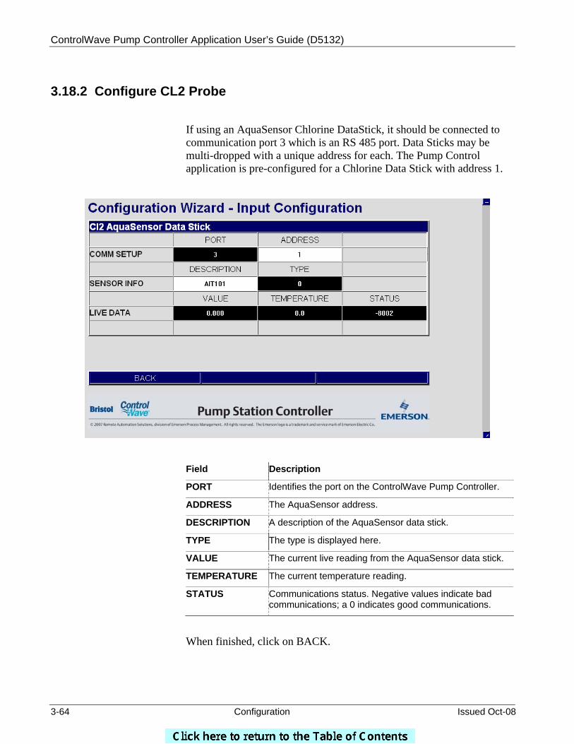
ControlWave Pump Controller Application User’s Guide (D5132)
3-64 Configuration Issued Oct-08
3.18.2 Configure CL2 Probe
If using an AquaSensor Chlorine DataStick, it should be connected to communication port 3 which is an RS 485 port. Data Sticks may be multi-dropped with a unique address for each. The Pump Control application is pre-configured for a Chlorine Data Stick with address 1.
Field Description
PORT Identifies the port on the ControlWave Pump Controller.
ADDRESS The AquaSensor address.
DESCRIPTION A description of the AquaSensor data stick.
TYPE The type is displayed here.
VALUE The current live reading from the AquaSensor data stick.
TEMPERATURE The current temperature reading.
STATUS Communications status. Negative values indicate bad communications; a 0 indicates good communications.
When finished, click on BACK.
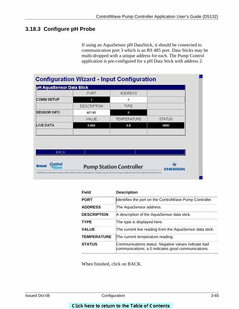
ControlWave Pump Controller Application User’s Guide (D5132)
Issued Oct-08 Configuration 3-65
3.18.3 Configure pH Probe
If using an AquaSensor pH DataStick, it should be connected to communication port 3 which is an RS 485 port. Data Sticks may be multi-dropped with a unique address for each. The Pump Control application is pre-configured for a pH Data Stick with address 2.
Field Description
PORT Identifies the port on the ControlWave Pump Controller.
ADDRESS The AquaSensor address.
DESCRIPTION A description of the AquaSensor data stick.
TYPE The type is displayed here.
VALUE The current live reading from the AquaSensor data stick.
TEMPERATURE The current temperature reading.
STATUS Communications status. Negative values indicate bad communications; a 0 indicates good communications.
When finished, click on BACK.

ControlWave Pump Controller Application User’s Guide (D5132)
3-66 Configuration Issued Oct-08
3.19 Recipe
When the configuration and setup is completed, click on ‘NEXT’ at the bottom of the page to advance to the Recipe page.
The Recipe page allows the user to save a set of initial values for the variables in the ControlWave Pump Controller application, in a file at the PC. The values to be saved in the recipe file can be loaded directly from the ControlWave Pump Controller application, or the user can type them in manually.
At any later time, the user can load the values from the file into the associated variables in the application. This can be useful, for example, if various tuning parameters for the optimum performance of the application have been determined, and they should be saved for later use. This also allows a pump control configuration to be easily modified for use at other similar pump sites without having to do re-do the entire configuration at the other sites.
A default recipe file is included that you can use to upload or download configuration values for the application. You may also edit this file, or create your own recipes as described in Section 3.19.1.
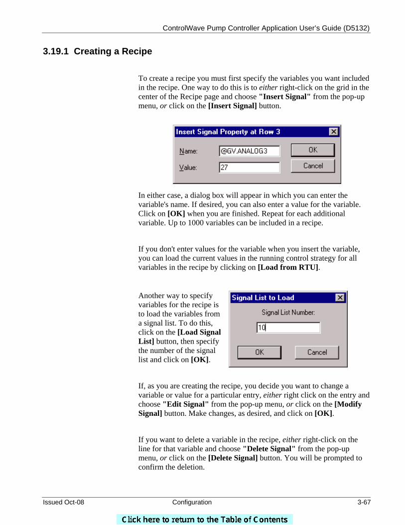
ControlWave Pump Controller Application User’s Guide (D5132)
Issued Oct-08 Configuration 3-67
3.19.1 Creating a Recipe
To create a recipe you must first specify the variables you want included in the recipe. One way to do this is to either right-click on the grid in the center of the Recipe page and choose "Insert Signal" from the pop-up menu, or click on the [Insert Signal] button.
In either case, a dialog box will appear in which you can enter the variable's name. If desired, you can also enter a value for the variable. Click on [OK] when you are finished. Repeat for each additional variable. Up to 1000 variables can be included in a recipe.
If you don't enter values for the variable when you insert the variable, you can load the current values in the running control strategy for all variables in the recipe by clicking on [Load from RTU].
Another way to specify variables for the recipe is to load the variables from a signal list. To do this, click on the [Load Signal List] button, then specify the number of the signal list and click on [OK].
If, as you are creating the recipe, you decide you want to change a variable or value for a particular entry, either right click on the entry and choose "Edit Signal" from the pop-up menu, or click on the [Modify Signal] button. Make changes, as desired, and click on [OK].
If you want to delete a variable in the recipe, either right-click on the line for that variable and choose "Delete Signal" from the pop-up menu, or click on the [Delete Signal] button. You will be prompted to confirm the deletion.
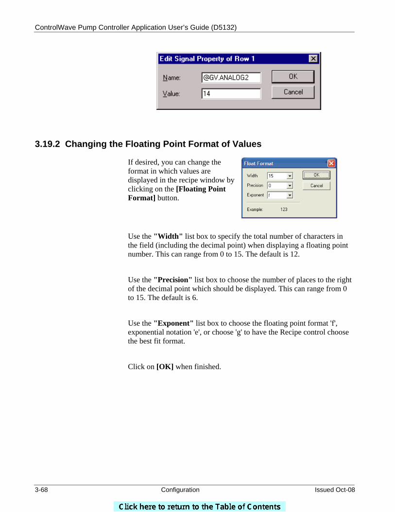
ControlWave Pump Controller Application User’s Guide (D5132)
3-68 Configuration Issued Oct-08
3.19.2 Changing the Floating Point Format of Values
If desired, you can change the format in which values are displayed in the recipe window by clicking on the [Floating Point Format] button.
Use the "Width" list box to specify the total number of characters in the field (including the decimal point) when displaying a floating point number. This can range from 0 to 15. The default is 12.
Use the "Precision" list box to choose the number of places to the right of the decimal point which should be displayed. This can range from 0 to 15. The default is 6.
Use the "Exponent" list box to choose the floating point format 'f', exponential notation 'e', or choose 'g' to have the Recipe control choose the best fit format.
Click on [OK] when finished.
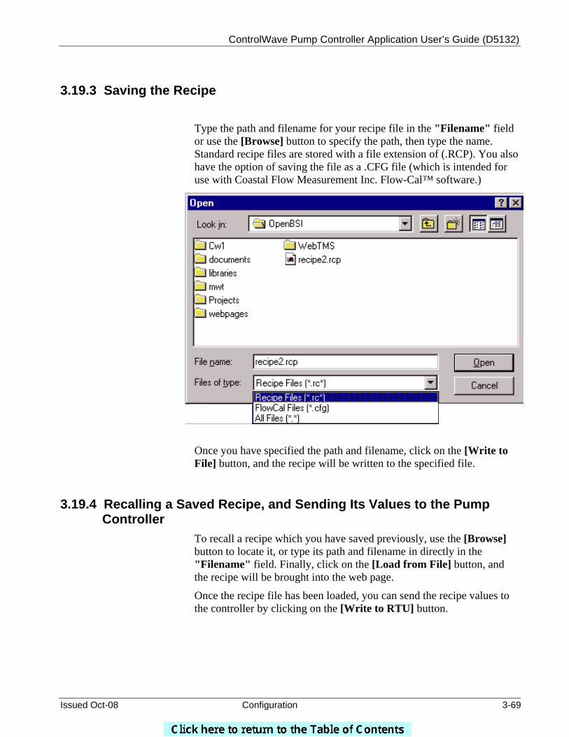
ControlWave Pump Controller Application User’s Guide (D5132)
Issued Oct-08 Configuration 3-69
3.19.3 Saving the Recipe
Type the path and filename for your recipe file in the "Filename" field or use the [Browse] button to specify the path, then type the name. Standard recipe files are stored with a file extension of (.RCP). You also have the option of saving the file as a .CFG file (which is intended for use with Coastal Flow Measurement Inc. Flow-Cal™ software.)
Once you have specified the path and filename, click on the [Write to File] button, and the recipe will be written to the specified file.
3.19.4 Recalling a Saved Recipe, and Sending Its Values to the Pump Controller
To recall a recipe which you have saved previously, use the [Browse] button to locate it, or type its path and filename in directly in the "Filename" field. Finally, click on the [Load from File] button, and the recipe will be brought into the web page.
Once the recipe file has been loaded, you can send the recipe values to the controller by clicking on the [Write to RTU] button.
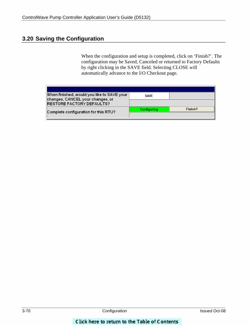
ControlWave Pump Controller Application User’s Guide (D5132)
3-70 Configuration Issued Oct-08
3.20 Saving the Configuration
When the configuration and setup is completed, click on ‘Finish?’. The configuration may be Saved, Canceled or returned to Factory Defaults by right clicking in the SAVE field. Selecting CLOSE will automatically advance to the I/O Checkout page.
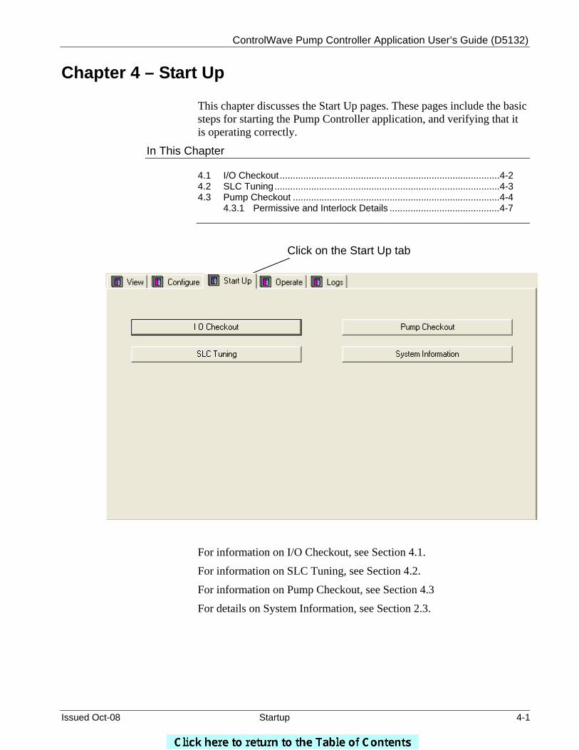
ControlWave Pump Controller Application User’s Guide (D5132)
Issued Oct-08 Startup 4-1
Chapter 4 – Start Up
This chapter discusses the Start Up pages. These pages include the basic steps for starting the Pump Controller application, and verifying that it is operating correctly.
In This Chapter
4.1 I/O Checkout ....................................................................................4-2 4.2 SLC Tuning......................................................................................4-3 4.3 Pump Checkout ...............................................................................4-4
4.3.1 Permissive and Interlock Details ..........................................4-7
For information on the IO Checkout screens, see Section 4.1.
For information on I/O Checkout, see Section 4.1.
For information on SLC Tuning, see Section 4.2.
For information on Pump Checkout, see Section 4.3
For details on System Information, see Section 2.3.
Click on the Start Up tab
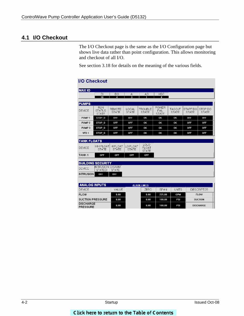
ControlWave Pump Controller Application User’s Guide (D5132)
4-2 Startup Issued Oct-08
4.1 I/O Checkout The I/O Checkout page is the same as the I/O Configuration page but shows live data rather than point configuration. This allows monitoring and checkout of all I/O.
See section 3.18 for details on the meaning of the various fields.

ControlWave Pump Controller Application User’s Guide (D5132)
Issued Oct-08 Startup 4-3
4.2 SLC Tuning
The SLC tuning page allows on-line tuning of the control loop. The setpoint is configurable as well as the KP, KI & KD tuning parameters. PV1 or PV2 may be manually selected or set to automatic for override control. The output can also be placed in manual mode to manually set the output valve.
Note: For a description of the tuning parameters and procedures, see the PID3TERM page of the ACCOL3 online help, in ControlWave Designer.
A live real-time trend is used to assist in optimizing the loop tuning.
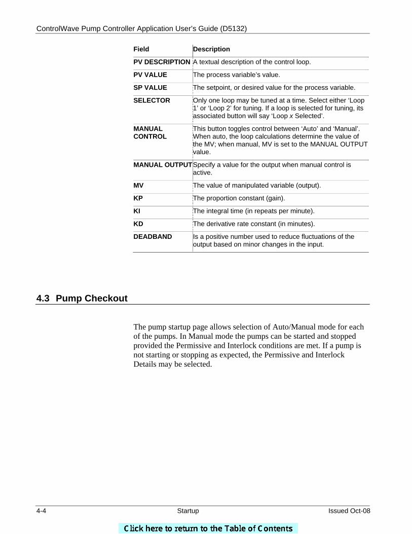
ControlWave Pump Controller Application User’s Guide (D5132)
4-4 Startup Issued Oct-08
Field Description
PV DESCRIPTION A textual description of the control loop.
PV VALUE The process variable’s value.
SP VALUE The setpoint, or desired value for the process variable.
SELECTOR Only one loop may be tuned at a time. Select either ‘Loop 1’ or ‘Loop 2’ for tuning. If a loop is selected for tuning, its associated button will say ‘Loop x Selected’.
MANUAL CONTROL
This button toggles control between ‘Auto’ and ‘Manual’. When auto, the loop calculations determine the value of the MV; when manual, MV is set to the MANUAL OUTPUT value.
MANUAL OUTPUTSpecify a value for the output when manual control is active.
MV The value of manipulated variable (output).
KP The proportion constant (gain).
KI The integral time (in repeats per minute).
KD The derivative rate constant (in minutes).
DEADBAND Is a positive number used to reduce fluctuations of the output based on minor changes in the input.
4.3 Pump Checkout
The pump startup page allows selection of Auto/Manual mode for each of the pumps. In Manual mode the pumps can be started and stopped provided the Permissive and Interlock conditions are met. If a pump is not starting or stopping as expected, the Permissive and Interlock Details may be selected.

ControlWave Pump Controller Application User’s Guide (D5132)
Issued Oct-08 Startup 4-5
Field Description
PUMP NAME The name of the pump.
COMPUTER A/M For each pump, a button is provided to toggle its mode between AUTO and MANUAL. The current mode is also displayed.
START A START button is provided for each pump. If the button label is ‘N/A’, the pump is not in MANUAL mode or not configured yet. The current running state of the pump is also displayed.
STOP A STOP button is provided for each pump. If the button label is ‘N/A’, the pump is not in MANUAL mode or not configured yet. The current running state of the pump is also displayed.
SPEED The field on the left shows the manual speed input; the field on the right is the actual speed.
AVAILABLE Displays whether or not the pump is available. If a pump is not available, it cannot be started/stopped.
REMOTE Displays whether the pump is in REMOTE mode.
LOCAL Displays whether the pump is in LOCAL mode.
PERMISSIVE If PERMIS is displayed, a permissive override is supported for this pump.
INTERLOCK If INTLCK is displayed, no override is allowed from any pump control.
ControlWave Pump Controller Application User’s Guide (D5132)
4-6 Startup Issued Oct-08
RUN STATUS Displays the current running status of the pump.
RUNTIME The accumulated running time of the pump is displayed here.
FAIL Indicates a pump failure. To clear the failure status indication, click on the RESET button.
Manually Starting/Stopping a Pump
To start or stop a pump, manually, follow these steps:
1. Check to see that the pump is currently in MANUAL mode. If not, click on the MANUAL? button, to put it into MANUAL mode.
2. Click on START? to start the pump, or STOP? to stop the pump.
3. Check the RUN STATUS field to whether the pump changes status, as desired.
4. If the pump does not start/stop as desired, check the permissive and interlock details, and review other possible error conditions.
To view information about overrides for each pump, click on PERMISSIVE AND INTERLOCK DETAILS and see Section 4.3.1.
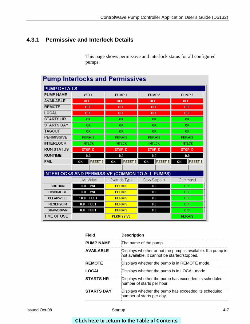
ControlWave Pump Controller Application User’s Guide (D5132)
Issued Oct-08 Startup 4-7
4.3.1 Permissive and Interlock Details
This page shows permissive and interlock status for all configured pumps.
Field Description
PUMP NAME The name of the pump.
AVAILABLE Displays whether or not the pump is available. If a pump is not available, it cannot be started/stopped.
REMOTE Displays whether the pump is in REMOTE mode.
LOCAL Displays whether the pump is in LOCAL mode.
STARTS HR Displays whether the pump has exceeded its scheduled number of starts per hour.
STARTS DAY Displays whether the pump has exceeded its scheduled number of starts per day.
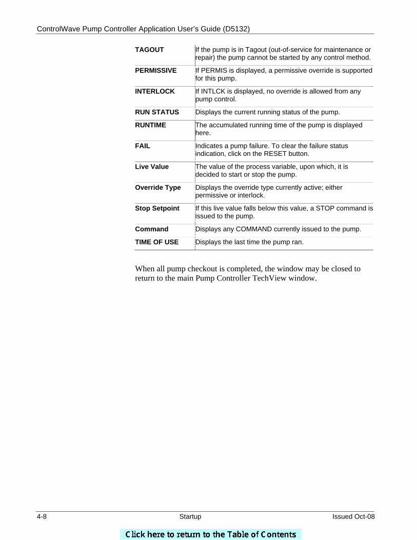
ControlWave Pump Controller Application User’s Guide (D5132)
4-8 Startup Issued Oct-08
TAGOUT If the pump is in Tagout (out-of-service for maintenance or repair) the pump cannot be started by any control method.
PERMISSIVE If PERMIS is displayed, a permissive override is supported for this pump.
INTERLOCK If INTLCK is displayed, no override is allowed from any pump control.
RUN STATUS Displays the current running status of the pump.
RUNTIME The accumulated running time of the pump is displayed here.
FAIL Indicates a pump failure. To clear the failure status indication, click on the RESET button.
Live Value The value of the process variable, upon which, it is decided to start or stop the pump.
Override Type Displays the override type currently active; either permissive or interlock.
Stop Setpoint If this live value falls below this value, a STOP command is issued to the pump.
Command Displays any COMMAND currently issued to the pump.
TIME OF USE Displays the last time the pump ran.
When all pump checkout is completed, the window may be closed to return to the main Pump Controller TechView window.
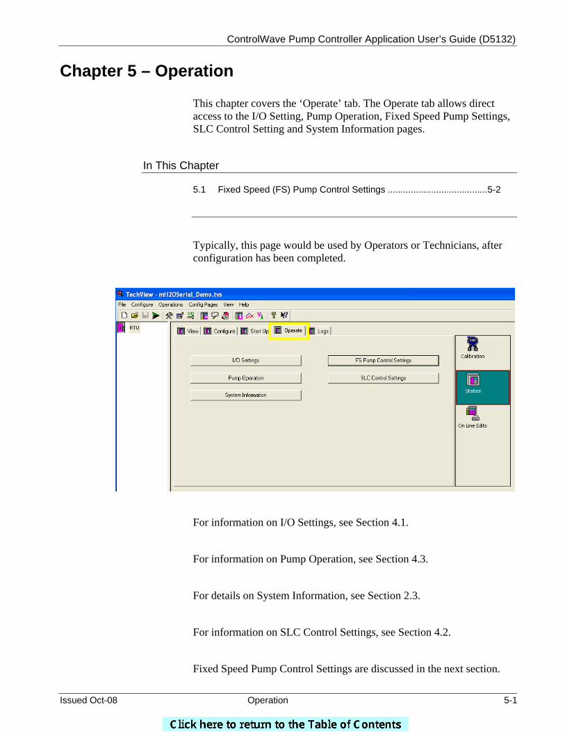
ControlWave Pump Controller Application User’s Guide (D5132)
Issued Oct-08 Operation 5-1
Chapter 5 – Operation
This chapter covers the ‘Operate’ tab. The Operate tab allows direct access to the I/O Setting, Pump Operation, Fixed Speed Pump Settings, SLC Control Setting and System Information pages.
In This Chapter
5.1 Fixed Speed (FS) Pump Control Settings .......................................5-2
Typically, this page would be used by Operators or Technicians, after configuration has been completed.
For information on I/O Settings, see Section 4.1.
For information on Pump Operation, see Section 4.3.
For details on System Information, see Section 2.3.
For information on SLC Control Settings, see Section 4.2.
Fixed Speed Pump Control Settings are discussed in the next section.
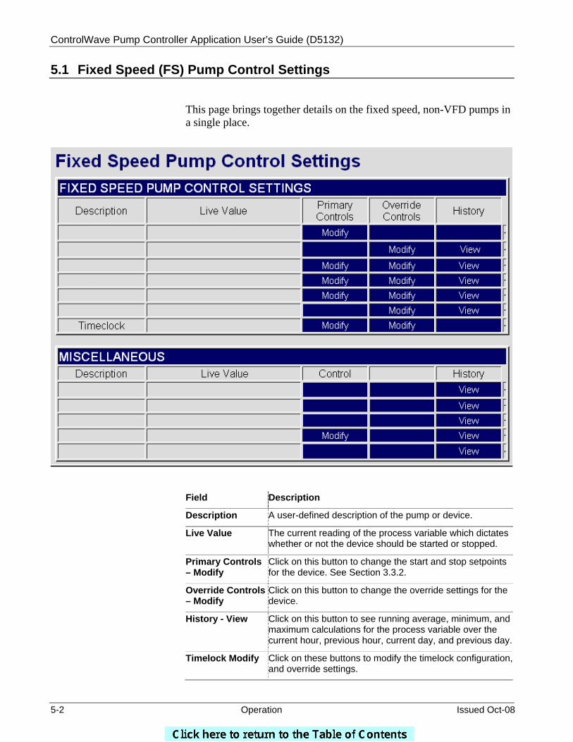
ControlWave Pump Controller Application User’s Guide (D5132)
5-2 Operation Issued Oct-08
5.1 Fixed Speed (FS) Pump Control Settings This page brings together details on the fixed speed, non-VFD pumps in a single place.
Field Description
Description A user-defined description of the pump or device.
Live Value The current reading of the process variable which dictates whether or not the device should be started or stopped.
Primary Controls – Modify
Click on this button to change the start and stop setpoints for the device. See Section 3.3.2.
Override Controls – Modify
Click on this button to change the override settings for the device.
History - View Click on this button to see running average, minimum, and maximum calculations for the process variable over the current hour, previous hour, current day, and previous day.
Timelock Modify Click on these buttons to modify the timelock configuration, and override settings.
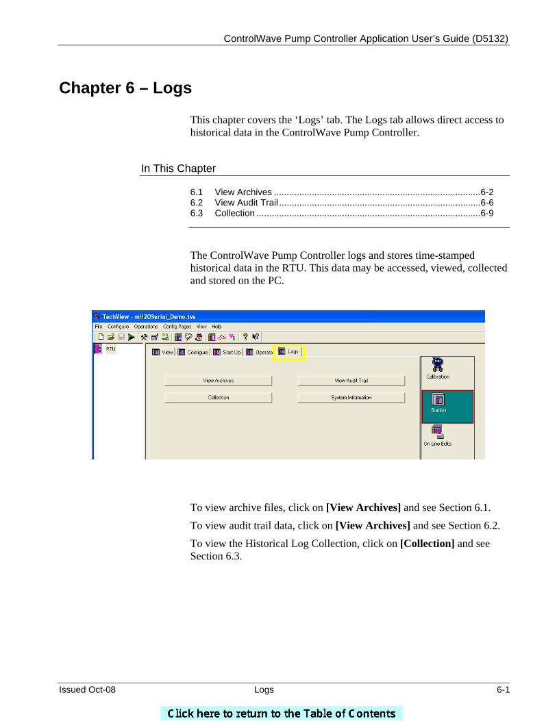
ControlWave Pump Controller Application User’s Guide (D5132)
Issued Oct-08 Logs 6-1
Chapter 6 – Logs
This chapter covers the ‘Logs’ tab. The Logs tab allows direct access to historical data in the ControlWave Pump Controller.
In This Chapter
6.1 View Archives ..................................................................................6-2 6.2 View Audit Trail ................................................................................6-6 6.3 Collection .........................................................................................6-9
The ControlWave Pump Controller logs and stores time-stamped historical data in the RTU. This data may be accessed, viewed, collected and stored on the PC.
To view archive files, click on [View Archives] and see Section 6.1.
To view audit trail data, click on [View Archives] and see Section 6.2.
To view the Historical Log Collection, click on [Collection] and see Section 6.3.
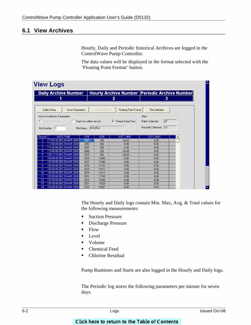
ControlWave Pump Controller Application User’s Guide (D5132)
6-2 Logs Issued Oct-08
6.1 View Archives
Hourly, Daily and Periodic historical Archives are logged in the ControlWave Pump Controller.
The data values will be displayed in the format selected with the ‘Floating Point Format’ button.
The Hourly and Daily logs contain Min. Max, Avg. & Total values for the following measurements:
Suction Pressure Discharge Pressure Flow Level Volume Chemical Feed Chlorine Residual
Pump Runtimes and Starts are also logged in the Hourly and Daily logs.
The Periodic log stores the following parameters per minute for seven days.
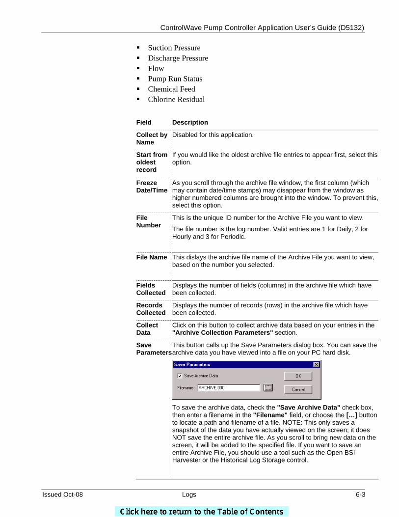
ControlWave Pump Controller Application User’s Guide (D5132)
Issued Oct-08 Logs 6-3
Suction Pressure Discharge Pressure Flow Pump Run Status Chemical Feed Chlorine Residual
Field Description
Collect by Name
Disabled for this application.
Start from oldest record
If you would like the oldest archive file entries to appear first, select this option.
Freeze Date/Time
As you scroll through the archive file window, the first column (which may contain date/time stamps) may disappear from the window as higher numbered columns are brought into the window. To prevent this, select this option.
File Number
This is the unique ID number for the Archive File you want to view.
The file number is the log number. Valid entries are 1 for Daily, 2 for Hourly and 3 for Periodic.
File Name This dislays the archive file name of the Archive File you want to view,
based on the number you selected.
Fields Collected
Displays the number of fields (columns) in the archive file which have been collected.
Records Collected
Displays the number of records (rows) in the archive file which have been collected.
Collect Data
Click on this button to collect archive data based on your entries in the "Archive Collection Parameters" section.
Save Parameters
This button calls up the Save Parameters dialog box. You can save the archive data you have viewed into a file on your PC hard disk.
To save the archive data, check the "Save Archive Data" check box, then enter a filename in the "Filename" field, or choose the […] button to locate a path and filename of a file. NOTE: This only saves a snapshot of the data you have actually viewed on the screen; it does NOT save the entire archive file. As you scroll to bring new data on the screen, it will be added to the specified file. If you want to save an entire Archive File, you should use a tool such as the Open BSI Harvester or the Historical Log Storage control.
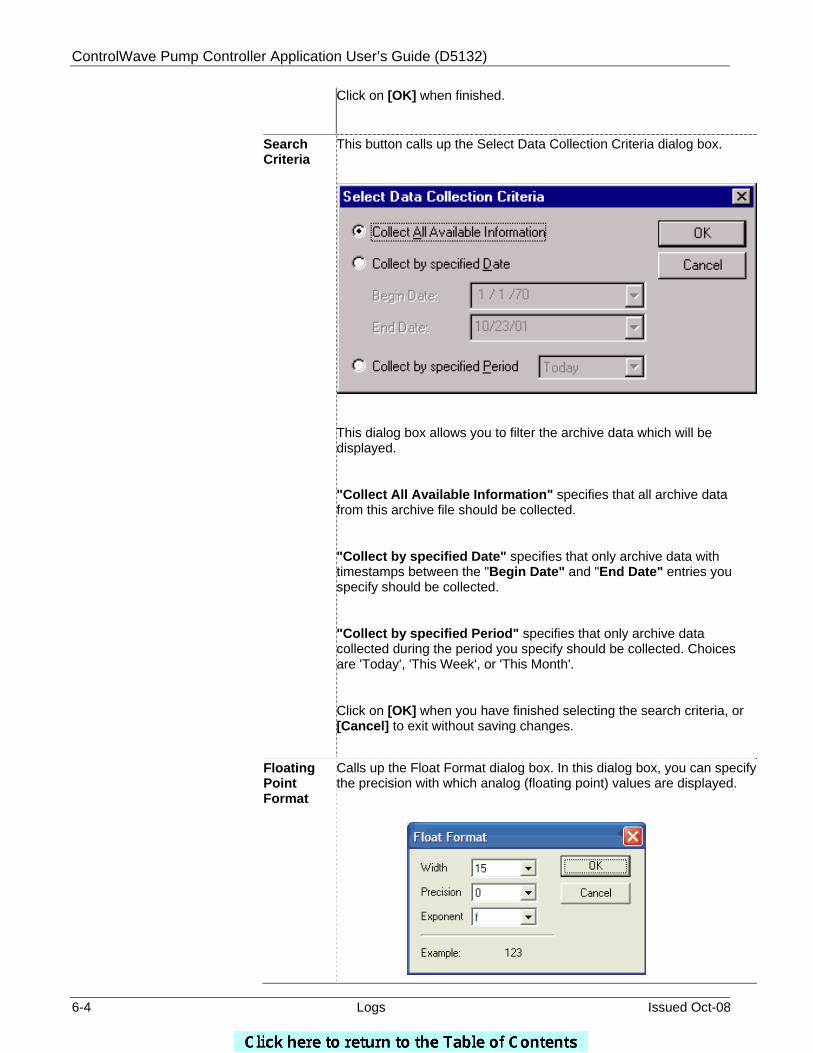
ControlWave Pump Controller Application User’s Guide (D5132)
6-4 Logs Issued Oct-08
Click on [OK] when finished.
Search Criteria
This button calls up the Select Data Collection Criteria dialog box.
This dialog box allows you to filter the archive data which will be displayed.
"Collect All Available Information" specifies that all archive data from this archive file should be collected.
"Collect by specified Date" specifies that only archive data with timestamps between the "Begin Date" and "End Date" entries you specify should be collected.
"Collect by specified Period" specifies that only archive data collected during the period you specify should be collected. Choices are 'Today', 'This Week', or 'This Month'.
Click on [OK] when you have finished selecting the search criteria, or [Cancel] to exit without saving changes.
Floating Point Format
Calls up the Float Format dialog box. In this dialog box, you can specify the precision with which analog (floating point) values are displayed.
ControlWave Pump Controller Application User’s Guide (D5132)
Issued Oct-08 Logs 6-5
Use the "Width" list box to specify the total number of characters in the field (including the decimal point) when displaying a floating point number. This can range from 1 to 15. The default is 12.
Use the "Precision" list box to choose the number of places to the right of the decimal point which should be displayed. This can range from 0 to 15. The default is 6.
Use the "Exponent" list box to choose the floating point format 'f', exponential notation 'e', or choose 'g' to have the Archive Collection control choose the best fit format.
Click on [OK] when finished.
File Definition
This button displays certain configuration parameters for this archive file, e.g. number of records. NOTE: These parameters CANNOT be changed here, they are only displayed.
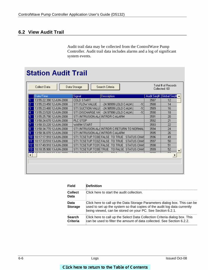
ControlWave Pump Controller Application User’s Guide (D5132)
6-6 Logs Issued Oct-08
6.2 View Audit Trail
Audit trail data may be collected from the ControlWave Pump Controller. Audit trail data includes alarms and a log of significant system events.
Field Definition
Collect Data
Click here to start the audit collection.
Data Storage
Click here to call up the Data Storage Parameters dialog box. This can be used to set up the system so that copies of the audit log data currently being viewed, can be stored on your PC. See Section 6.2.1.
Search Criteria
Click here to call up the Select Data Collection Criteria dialog box. This can be used to filter the amount of data collected. See Section 6.2.2.
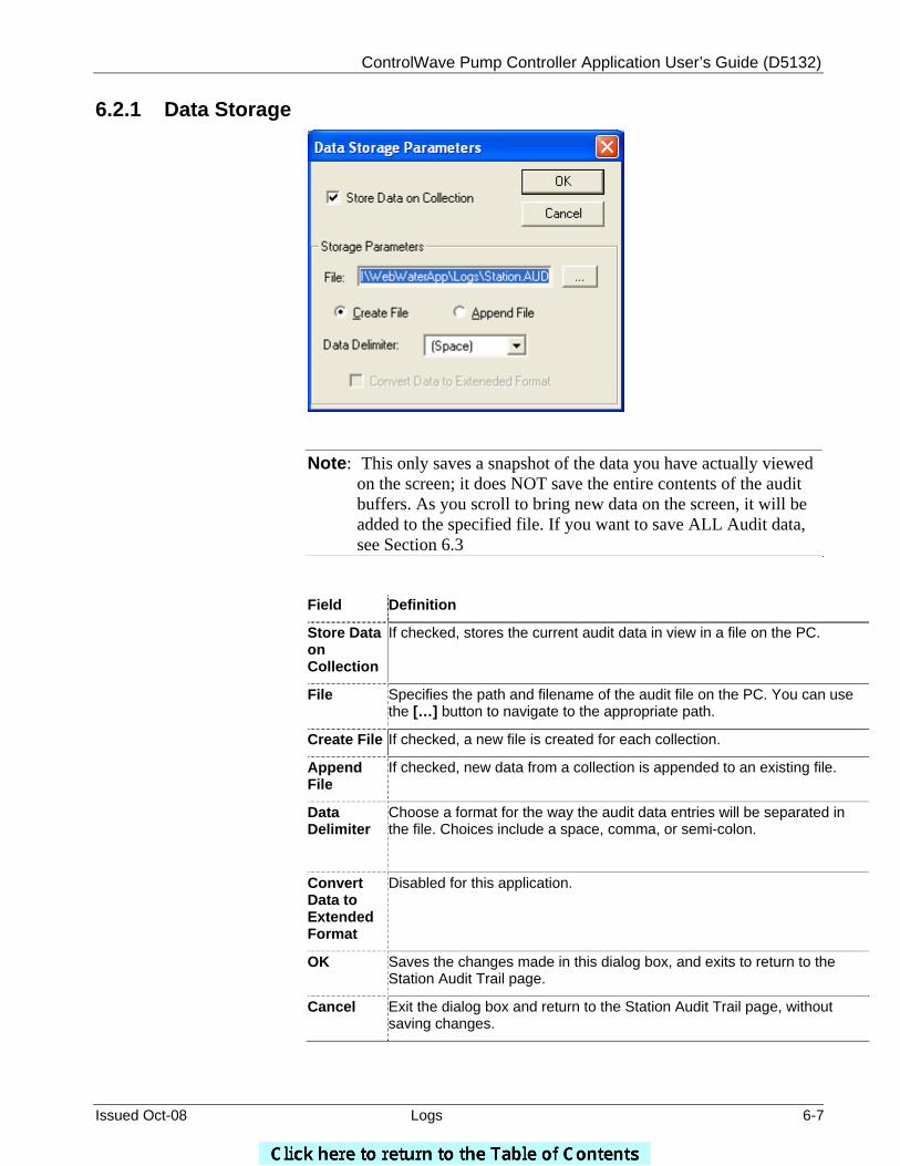
ControlWave Pump Controller Application User’s Guide (D5132)
Issued Oct-08 Logs 6-7
6.2.1 Data Storage
Note: This only saves a snapshot of the data you have actually viewed on the screen; it does NOT save the entire contents of the audit buffers. As you scroll to bring new data on the screen, it will be added to the specified file. If you want to save ALL Audit data, see Section 6.3
Field Definition
Store Data on Collection
If checked, stores the current audit data in view in a file on the PC.
File Specifies the path and filename of the audit file on the PC. You can use the […] button to navigate to the appropriate path.
Create File If checked, a new file is created for each collection.
Append File
If checked, new data from a collection is appended to an existing file.
Data Delimiter
Choose a format for the way the audit data entries will be separated in the file. Choices include a space, comma, or semi-colon.
Convert Data to Extended Format
Disabled for this application.
OK Saves the changes made in this dialog box, and exits to return to the Station Audit Trail page.
Cancel Exit the dialog box and return to the Station Audit Trail page, without saving changes.
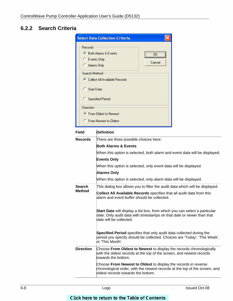
ControlWave Pump Controller Application User’s Guide (D5132)
6-8 Logs Issued Oct-08
6.2.2 Search Criteria
Field Definition
Records There are three possible choices here:
Both Alarms & Events
When this option is selected, both alarm and event data will be displayed.
Events Only
When this option is selected, only event data will be displayed.
Alarms Only
When this option is selected, only alarm data will be displayed.
Search Method
This dialog box allows you to filter the audit data which will be displayed.
Collect All Available Records specifies that all audit data from this alarm and event buffer should be collected.
Start Date will display a list box, from which you can select a particular date. Only audit data with timestamps on that date or newer than that date will be collected.
Specified Period specifies that only audit data collected during the period you specify should be collected. Choices are 'Today', 'This Week', or 'This Month'.
Direction Choose From Oldest to Newest to display the records chronologically with the oldest records at the top of the screen, and newest records towards the bottom.
Choose From Newest to Oldest to display the records in reverse chronological order, with the newest records at the top of the screen, and oldest records towards the bottom.
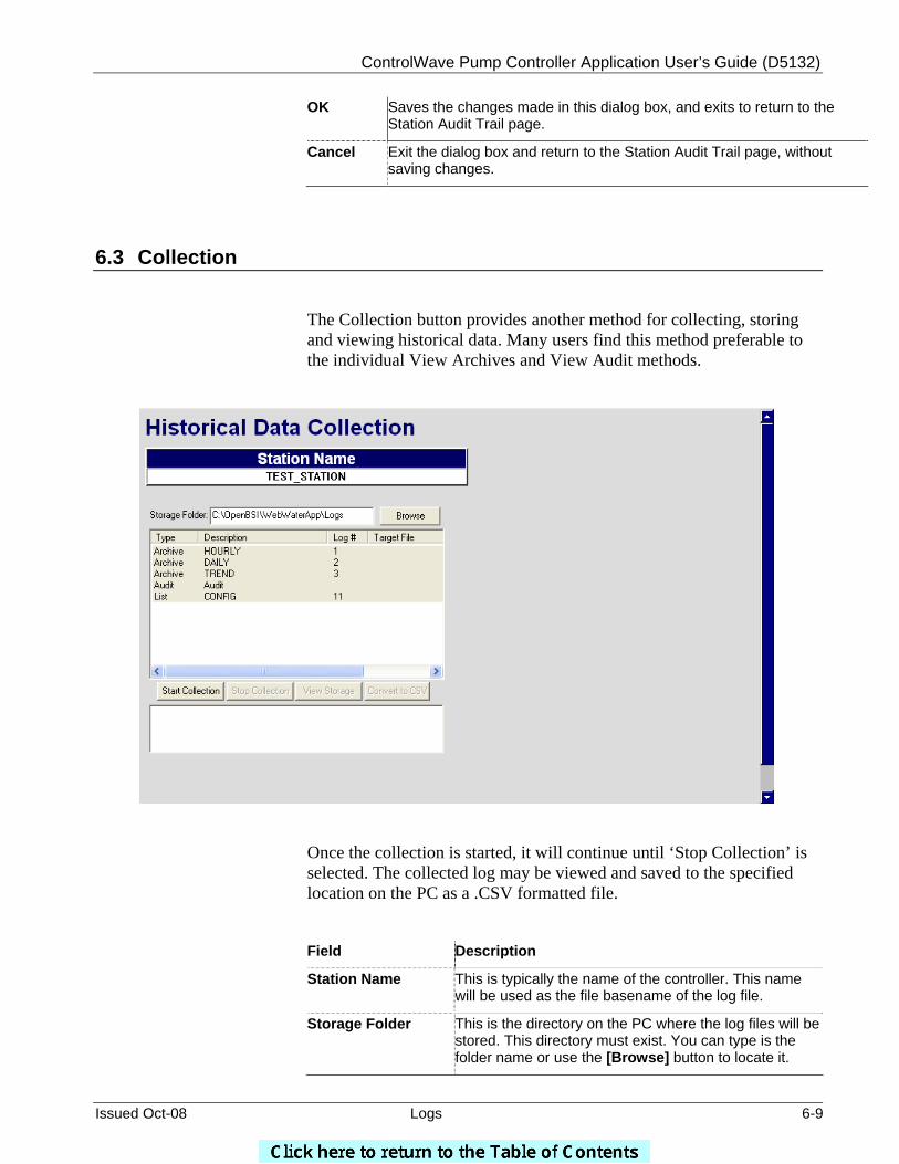
ControlWave Pump Controller Application User’s Guide (D5132)
Issued Oct-08 Logs 6-9
OK Saves the changes made in this dialog box, and exits to return to the Station Audit Trail page.
Cancel Exit the dialog box and return to the Station Audit Trail page, without saving changes.
6.3 Collection
The Collection button provides another method for collecting, storing and viewing historical data. Many users find this method preferable to the individual View Archives and View Audit methods.
Once the collection is started, it will continue until ‘Stop Collection’ is selected. The collected log may be viewed and saved to the specified location on the PC as a .CSV formatted file.
Field Description
Station Name This is typically the name of the controller. This name will be used as the file basename of the log file.
Storage Folder This is the directory on the PC where the log files will be stored. This directory must exist. You can type is the folder name or use the [Browse] button to locate it.
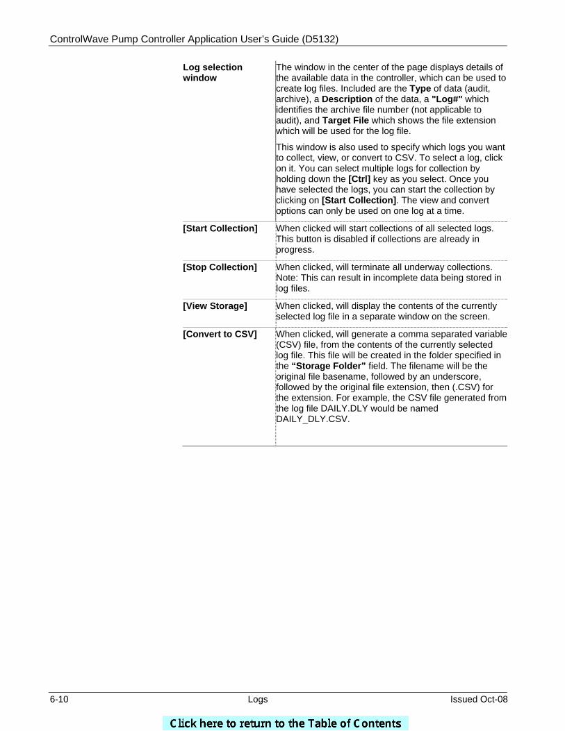
ControlWave Pump Controller Application User’s Guide (D5132)
6-10 Logs Issued Oct-08
Log selection window
The window in the center of the page displays details of the available data in the controller, which can be used to create log files. Included are the Type of data (audit, archive), a Description of the data, a "Log#" which identifies the archive file number (not applicable to audit), and Target File which shows the file extension which will be used for the log file.
This window is also used to specify which logs you want to collect, view, or convert to CSV. To select a log, click on it. You can select multiple logs for collection by holding down the [Ctrl] key as you select. Once you have selected the logs, you can start the collection by clicking on [Start Collection]. The view and convert options can only be used on one log at a time.
[Start Collection] When clicked will start collections of all selected logs. This button is disabled if collections are already in progress.
[Stop Collection] When clicked, will terminate all underway collections. Note: This can result in incomplete data being stored in log files.
[View Storage] When clicked, will display the contents of the currently selected log file in a separate window on the screen.
[Convert to CSV] When clicked, will generate a comma separated variable (CSV) file, from the contents of the currently selected log file. This file will be created in the folder specified in the “Storage Folder” field. The filename will be the original file basename, followed by an underscore, followed by the original file extension, then (.CSV) for the extension. For example, the CSV file generated from the log file DAILY.DLY would be named DAILY_DLY.CSV.

BLANK PAGE
User’s Guide
D5132 October, 2008
Bristol ControlWave Pump Controller Application
NOTICE “Remote Automation Solutions (“RAS”), division of Emerson Process Management shall not be liable for technical or editorial errors in this manual or omissions from this manual. RAS MAKES NO WARRANTIES, EXPRESSED OR IMPLIED, INCLUDING THE IMPLIED WARRANTIES OF MERCHANTABILITY AND FITNESS FOR A PARTICULAR PURPOSE WITH RESPECT TO THIS MANUAL AND, IN NO EVENT SHALL RAS BE LIABLE FOR ANY INCIDENTAL, PUNITIVE, SPECIAL OR CONSEQUENTIAL DAMAGES INCLUDING, BUT NOT LIMITED TO, LOSS OF PRODUCTION, LOSS OF PROFITS, LOSS OF REVENUE OR USE AND COSTS INCURRED INCLUDING WITHOUT LIMITATION FOR CAPITAL, FUEL AND POWER, AND CLAIMS OF THIRD PARTIES. Bristol, Inc., Bristol Canada, BBI SA de CV and Emerson Process Management Ltd, Remote Automation Solutions division (UK), are wholly owned subsidiaries of Emerson Electric Co. doing business as Remote Automation Solutions (“RAS”), a division of Emerson Process Management. FloBoss, ROCLINK, Bristol, Bristol Babcock, ControlWave, TeleFlow and Helicoid are trademarks of RAS. AMS, PlantWeb and the PlantWeb logo are marks of Emerson Electric Co. The Emerson logo is a trademark and service mark of the Emerson Electric Co. All other trademarks are property of their respective owners. The contents of this publication are presented for informational purposes only. While every effort has been made to ensure informational accuracy, they are not to be construed as warranties or guarantees, express or implied, regarding the products or services described herein or their use or applicability. RAS reserves the right to modify or improve the designs or specifications of such products at any time without notice. All sales are governed by RAS’ terms and conditions which are available upon request. RAS does not assume responsibility for the selection, use or maintenance of any product. Responsibility for proper selection, use and maintenance of any RAS product remains solely with the purchaser and end-user. ” © 2008 Remote Automation Solutions, division of Emerson Process Management. All rights reserved.
Emerson Process Management Remote Automation Solutions 1100 Buckingham Street Watertown, CT 06795 Phone: +1 (860) 945-2262 Fax: +1 (860) 945-2525 www.EmersonProcess.com/Remote Emerson Process Management Remote Automation Solutions 6338 Viscount Rd. Mississauga, Ont. L4V 1H3 Canada Phone: 905-362-0880 Fax: 905-362-0882 www.EmersonProcess.com/Remote Emerson Process Management Mexico Viveros de la Colina No 238 Col. Viveros de la Loma Tlalnepantla, Mexico 54080 T +52 (55) 57.28.08.00 F +52 (55) 53.66.26.18 www.EmersonProcess.com/Remote Emerson Process Management, Ltd. Remote Automation Solutions Blackpole Road Worcester, WR3 8YB United Kingdom Phone: +44 1905 856950 Fax: +44 1905 856969 www.EmersonProcess.com/Remote Emerson Process Management AP Pte Ltd. Remote Automation Solutions Division 1 Pandan Crescent Singapore 128461 Phone: +65-6770-8584 Fax: +65-6891-7841 www.EmersonProcess.com/Remote