Controlling light with metamaterial-based Photonic ... · dimensional periodic and quasi-periodic...
17
SUPPLEMENTARY INFORMATION DOI: 10.1038/NPHOTON.2015.17 NATURE PHOTONICS | www.nature.com/naturephotonics 1 Nadav Segal, Shay Keren-Zur, Netta Hendler, Tal Ellenbogen * Department of Physical Electronics, Fleischman Faculty of Engineering, Tel-Aviv University, Tel-Aviv 69978, Israel Corresponding author e-mail address: [email protected]; [email protected] Supplementary Section I: Numerical simulation based on a hydrodynamic model The Hydrodynamic Model The hydrodynamic model describes the nonlinear optical response of the charge carriers in the metal. It is based on modeling the electron fluid by Euler’s equation where n(r,t) represent the electron fluid density and v(r,t) represent the electron velocity field. ∂ ∂ + ( ∙ ∇) + = ∗ ( + × ) − 2 ∇ (1) − electron collision rate ∝ Fermi velocity ∇ ∙ = −̇ ( = ) (2) ∗ − electron effective mass After expanding all fields in a perturbative manner, it is possible to extract the nonlinear current terms which depend on the bulk polarization (1, 2 and refs. within): = 0 [ ̂ ( 1 ⊥ 1 ∥ )+ 1 2 3+ 2+ ( 1 ⊥ ) 2 ] (3) Controlling light with metamaterial-based nonlinear photonic crystals © 2015 Macmillan Publishers Limited. All rights reserved
Transcript of Controlling light with metamaterial-based Photonic ... · dimensional periodic and quasi-periodic...
SUPPLEMENTARY INFORMATIONDOI: 10.1038/NPHOTON.2015.17
NATURE PHOTONICS | www.nature.com/naturephotonics 1
Supplementary Information:
Controlling Light by Metamaterial based Nonlinear
Photonic Crystals
Nadav Segal, Shay Keren-Zur, Netta Hendler, Tal Ellenbogen*
Department of Physical Electronics, Fleischman Faculty of Engineering, Tel-Aviv University,
Tel-Aviv 69978, Israel
Corresponding author e-mail address: [email protected]; [email protected]
Supplementary Section I: Numerical simulation based on a hydrodynamic model
The Hydrodynamic Model
The hydrodynamic model describes the nonlinear optical response of the charge carriers in the
metal. It is based on modeling the electron fluid by Euler’s equation where n(r,t) represent the
electron fluid density and v(r,t) represent the electron velocity field.
∂𝐯𝐯∂𝑡𝑡 + (𝐯𝐯 ∙ ∇)𝐯𝐯 + 𝛾𝛾𝐯𝐯 = 𝑒𝑒
𝑚𝑚𝑒𝑒∗(𝐄𝐄 + 𝐯𝐯 × 𝐁𝐁) − 𝛽𝛽2
𝑛𝑛 ∇𝑛𝑛 (1) 𝛾𝛾 − electron collision rate
𝛽𝛽 ∝ Fermi velocity 𝐯𝐯𝐹𝐹
∇ ∙ 𝐉𝐉 = −𝑒𝑒�̇�𝑛 (𝐉𝐉 = 𝑒𝑒𝑛𝑛𝐯𝐯) (2) 𝑚𝑚𝑒𝑒∗ − electron effective mass
After expanding all fields in a perturbative manner, it is possible to extract the nonlinear current
terms which depend on the bulk polarization (1, 2 and refs. within):
𝐉𝐉𝑁𝑁𝑁𝑁 = 𝑖𝑖𝑖𝑖𝑛𝑛0𝑒𝑒 [�̂�𝐭(𝑃𝑃1
⊥𝑃𝑃1∥) + �̂�𝐧 1
23𝑖𝑖+𝑖𝑖𝑖𝑖2𝑖𝑖+𝑖𝑖𝑖𝑖
(𝑃𝑃1⊥)2] (3)
Controlling light with metamaterial-based nonlinear photonic crystals
© 2015 Macmillan Publishers Limited. All rights reserved

2
Supplementary Figure 1: Numerical simulation. (a) Illustrates one of the simulated SRR
geometrical configurations. The height of the SRR is 30nm. (b) Currents (arrows) and near-field
radiation patterns (color scale) from a uniform array for FH and (c) SH. The near-field radiation
patterns were taken 100nm above the SRRs. In the simulation we insert the obtained linear
polarization in b into Equation 3 to produce the currents and radiation at the SH shown in c. (d)
Inverted particles produce nonlinear radiation pattern with phase shift. This is the mechanism
used to construct the NLMPCs.
Supplementary Figure 2: Illustration of point-of-view of simulation results shown in Fig. 1
of the manuscript. (a) Simulation results of near-field at the FH and emitted SH for uniform
arrays. (b) Illustration of the simulation point-of-view.
© 2015 Macmillan Publishers Limited. All rights reserved
3
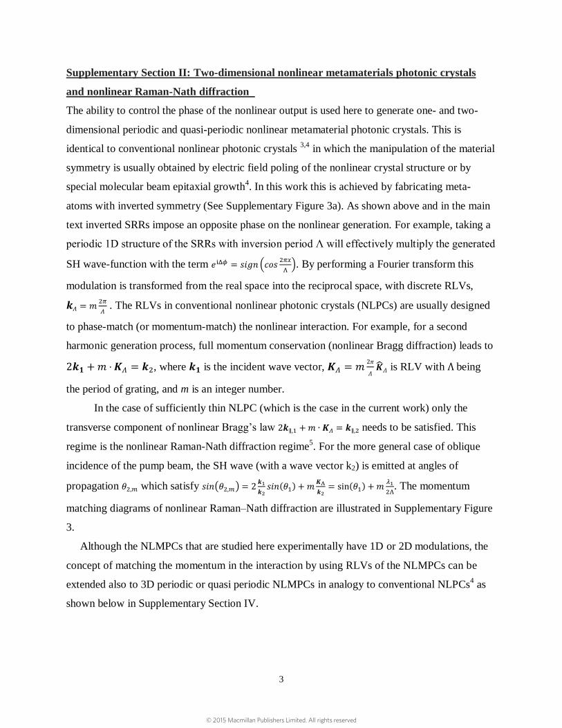
Supplementary Section II: Two-dimensional nonlinear metamaterials photonic crystals
and nonlinear Raman-Nath diffraction
The ability to control the phase of the nonlinear output is used here to generate one- and two-
dimensional periodic and quasi-periodic nonlinear metamaterial photonic crystals. This is
identical to conventional nonlinear photonic crystals 3,4
in which the manipulation of the material
symmetry is usually obtained by electric field poling of the nonlinear crystal structure or by
special molecular beam epitaxial growth4. In this work this is achieved by fabricating meta-
atoms with inverted symmetry (See Supplementary Figure 3a). As shown above and in the main
text inverted SRRs impose an opposite phase on the nonlinear generation. For example, taking a
periodic 1D structure of the SRRs with inversion period Λ will effectively multiply the generated
SH wave-function with the term 𝑒iΔ𝜙 = 𝑠𝑖𝑔𝑛 (𝑐𝑜𝑠2𝜋𝑥
Λ). By performing a Fourier transform this
modulation is transformed from the real space into the reciprocal space, with discrete RLVs,
𝒌𝛬 = 𝑚2𝜋
𝛬 . The RLVs in conventional nonlinear photonic crystals (NLPCs) are usually designed
to phase-match (or momentum-match) the nonlinear interaction. For example, for a second
harmonic generation process, full momentum conservation (nonlinear Bragg diffraction) leads to
2𝒌𝟏 + 𝑚 ∙ 𝑲𝛬 = 𝒌2, where 𝒌𝟏 is the incident wave vector, 𝑲𝛬 = 𝑚2𝜋
𝛬�̂�𝛬 is RLV with Λ being
the period of grating, and m is an integer number.
In the case of sufficiently thin NLPC (which is the case in the current work) only the
transverse component of nonlinear Bragg’s law 2𝒌∥,1 + 𝑚 ∙ 𝑲𝛬 = 𝒌∥,2 needs to be satisfied. This
regime is the nonlinear Raman-Nath diffraction regime5. For the more general case of oblique
incidence of the pump beam, the SH wave (with a wave vector k2) is emitted at angles of
propagation 𝜃2,𝑚 which satisfy 𝑠𝑖𝑛(𝜃2,𝑚) = 2𝒌1
𝒌2𝑠𝑖𝑛(𝜃1) + 𝑚
𝑲Λ
𝒌2= sin (𝜃1) + 𝑚
𝜆1
2Λ. The momentum
matching diagrams of nonlinear Raman–Nath diffraction are illustrated in Supplementary Figure
3.
Although the NLMPCs that are studied here experimentally have 1D or 2D modulations, the
concept of matching the momentum in the interaction by using RLVs of the NLMPCs can be
extended also to 3D periodic or quasi periodic NLMPCs in analogy to conventional NLPCs4 as
shown below in Supplementary Section IV.
© 2015 Macmillan Publishers Limited. All rights reserved
4
Supplementary Figure 3: Nonlinear Metamaterials Photonic Crystal and Raman-Nath
diffraction. (a) Exemplified real space and the appropriate reciprocal space of NLMPC with
one-dimensional modulation. (b) Phase-matching conditions for nonlinear Raman–Nath
diffraction for normal and (c) oblique incidence.
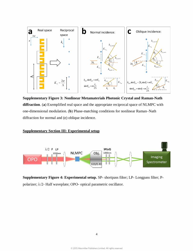
Supplementary Section III: Experimental setup
Supplementary Figure 4: Experimental setup. SP- shortpass filter; LP- Longpass filter; P-
polarizer; /2- Half waveplate; OPO- optical parametric oscillator.
© 2015 Macmillan Publishers Limited. All rights reserved

5
Supplementary Figure 5: Spectral measurement of the SH. Measurement of the SH emitted
from a uniform array which was illuminated with FH with 1200 nm wavelength. The
spectrometer was Andor Shamrock 303i with Newton 970 camera.
Supplementary Section IV: Increasing conversion efficiency by three-dimensional
NLMPCs
The ability to generate materials with artificial nonlinearity is exciting; however so far the
nonlinear metamaterials that were studied were made from extremely thin surfaces. One way to
increase the total nonlinear conversion efficiency is to use advanced fabrication methods6 to
construct three-dimensional metamaterials that provide longer interaction lengths.
However, in the case of multilayered metamaterials there are some considerations that have to
be taken into account, including phase matching of the nonlinear interaction, reflection,
transmission and absorption of the waves in the multilayered structures. These considerations
make the wave dynamics in nonlinear multilayered metamaterials much more complex in
comparison to conventional nonlinear materials.
In the following section we describe the problem in more details, analyze analytically and
numerically the major implications of stacking multiple layers for forming three-dimensional
nonlinear metamaterials and NLMPCs and show that by understanding the fundamental
problems of this configuration the total conversion efficiency can be increased substantially by
© 2015 Macmillan Publishers Limited. All rights reserved

6
using multilayered structures. In our studies we show about 500-fold increase of the total power
conversion efficiency in comparison to the performance of a single layer resonant SRR structure
which was studied before1. We believe that additional future studies can lead to even better
improvements in the conversion efficiencies of multilayered nonlinear metamaterials.
Quasi-phase-matching:
Momentum mismatch between the waves (for SHG Δ𝑘 = 𝑘𝑆𝐻 − 2𝑘𝐹𝐻), that is caused from
material dispersion, usually leads to accumulated phase mismatch as the waves propagate
resulting in a destructive interference of the generated nonlinear signal. Therefore, without phase
matching, the nonlinear interaction is inefficient even for thick, three-dimensional, nonlinear
materials.
In conventional materials the common solution to the phase matching problem is to use
birefringence7 in uniaxial or biaxial nonlinear crystals, or quasi-phase-matching (QPM) in poled
NLPCs8. NLPCs are widely used to control nonlinear optical interactions since in addition to
generating efficient nonlinear signal, they prevent walk-off of the interacting beams and enable
adjusting other aspects of the interaction such as the direction of the generated beams3 and their
spatial shape9,10
. Moreover, NLPCs can be used for active devices11
and efficient generation of
entangled photon pairs12
. Our work presented in the manuscript demonstrates experimentally
two-dimensional NLMPCs and gives motivation to create three-dimensional NLMPCs and to use
them for QPM and additional manipulations of nonlinear interactions.
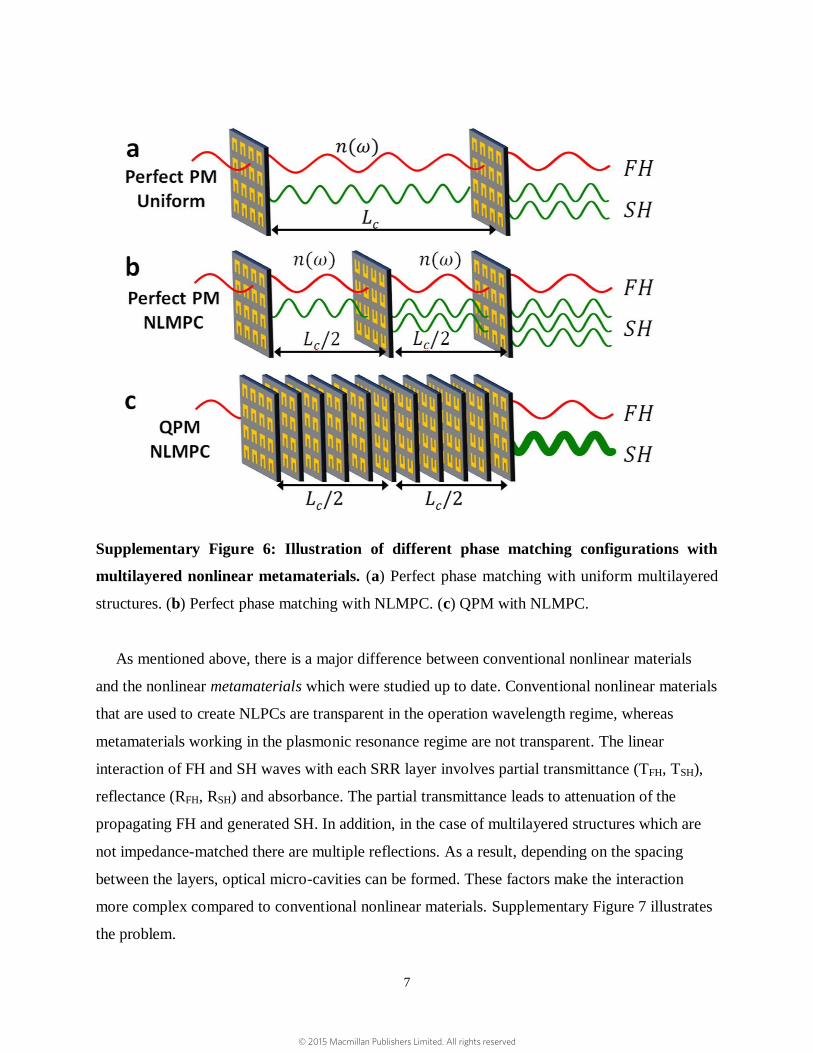
Supplementary Figure 6 illustrates three different phase matching schemes in three-
dimensional metamaterials based on multiple SRRs layers. Perfect phase matching can be
achieved by placing different SRR layers of the same orientation spaced at coherence lengths
(𝐿𝑐 = 2𝜋/Δ𝑘 ) or by placing the SRR layers at half coherence lengths and flipping the
orientation of the SRRs (and phase of nonlinear output) in successive layers. QPM can be
achieved by closely packing the SRR layers and flipping different regions of the structures (at
half coherence length distance). This is the same method which is used for construction of
conventional NLPCs where the inversion of (2)
is used to impose π phase shifts on the locally
generated radiation. Using QPM for the multilayered metamaterial structure will result in much
higher conversion efficiency per propagation length, since it allows packing many more SRR
layers in the same region in space.
© 2015 Macmillan Publishers Limited. All rights reserved
7
Supplementary Figure 6: Illustration of different phase matching configurations with
multilayered nonlinear metamaterials. (a) Perfect phase matching with uniform multilayered
structures. (b) Perfect phase matching with NLMPC. (c) QPM with NLMPC.
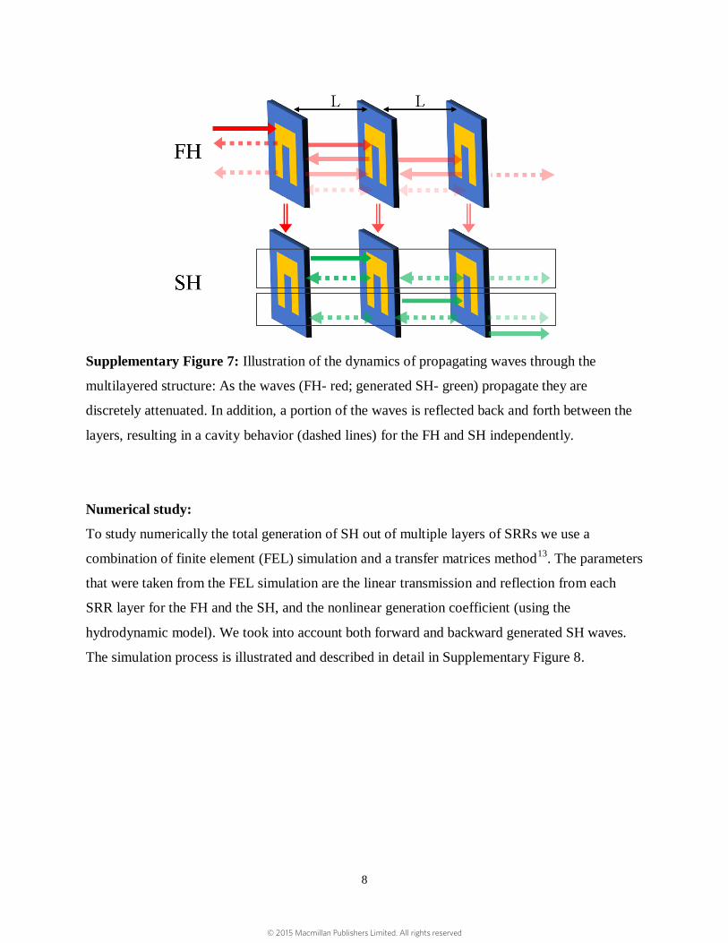
As mentioned above, there is a major difference between conventional nonlinear materials
and the nonlinear metamaterials which were studied up to date. Conventional nonlinear materials
that are used to create NLPCs are transparent in the operation wavelength regime, whereas
metamaterials working in the plasmonic resonance regime are not transparent. The linear
interaction of FH and SH waves with each SRR layer involves partial transmittance (TFH, TSH),
reflectance (RFH, RSH) and absorbance. The partial transmittance leads to attenuation of the
propagating FH and generated SH. In addition, in the case of multilayered structures which are
not impedance-matched there are multiple reflections. As a result, depending on the spacing
between the layers, optical micro-cavities can be formed. These factors make the interaction
more complex compared to conventional nonlinear materials. Supplementary Figure 7 illustrates
the problem.
© 2015 Macmillan Publishers Limited. All rights reserved
8
Supplementary Figure 7: Illustration of the dynamics of propagating waves through the
multilayered structure: As the waves (FH- red; generated SH- green) propagate they are
discretely attenuated. In addition, a portion of the waves is reflected back and forth between the
layers, resulting in a cavity behavior (dashed lines) for the FH and SH independently.
Numerical study:
To study numerically the total generation of SH out of multiple layers of SRRs we use a
combination of finite element (FEL) simulation and a transfer matrices method13
. The parameters
that were taken from the FEL simulation are the linear transmission and reflection from each
SRR layer for the FH and the SH, and the nonlinear generation coefficient (using the
hydrodynamic model). We took into account both forward and backward generated SH waves.
The simulation process is illustrated and described in detail in Supplementary Figure 8.
© 2015 Macmillan Publishers Limited. All rights reserved

9
Supplementary Figure 8: Illustration of simulation process for N layers: FEL simulation
produces linear transmission and reflection coefficients and the generated SH fields from each
single layer. The linear coefficients are used in the transfer matrix formulation to calculate the
FH everywhere in the multilayered structure. The local FH in the nth
layer is used to calculate the
locally generated SH in the nth
layer. The locally generated SH is fed to the SH transfer matrix
formulation which takes into account all the layers before and after the locally generated SH and
calculates the contribution of the locally generated SH in each layer to the output SH. The total
output SH is calculated as the sum of contributions of the locally generated SH from each layer
after interacting with the entire multilayered structure.
Results of numerical study:
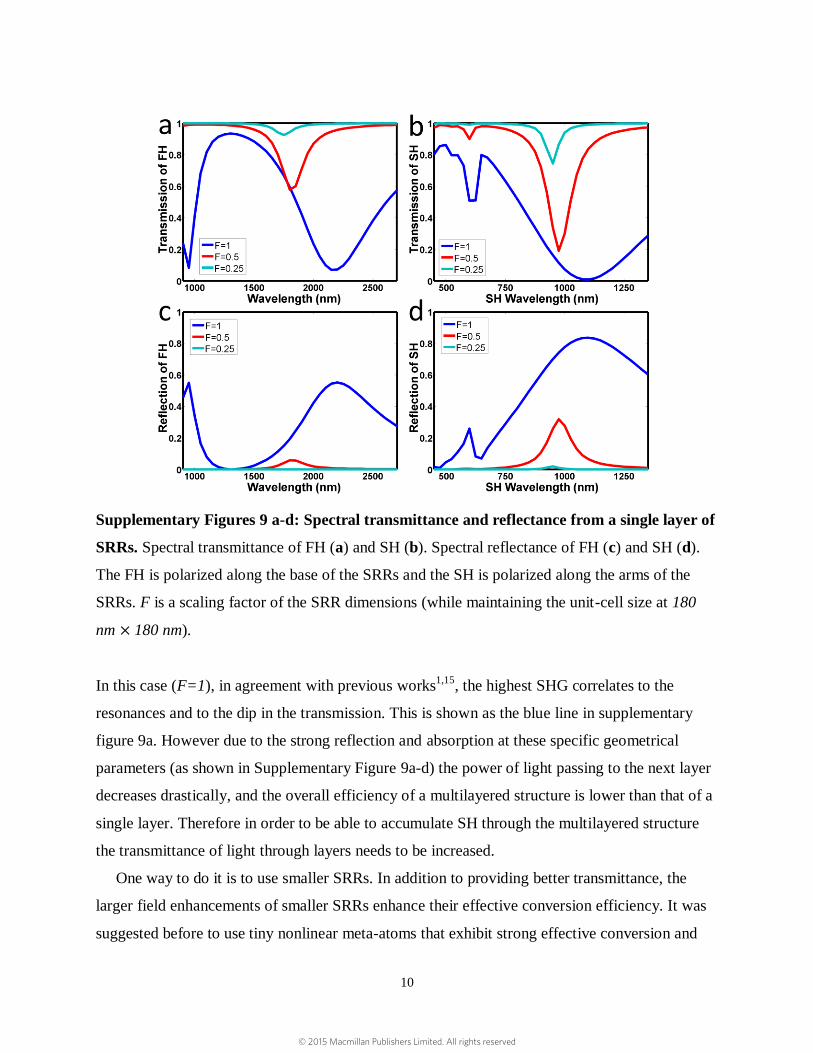
We started by examining the SHG from a single layer of SRRs with dimensions and unit-cell
size which were studied before by Ciraci et al.1, in a more realistic configuration for a
multilayered structure where the structure is embedded in silica glass14
. This added dispersion to
the problem (and need for phase matching) and led to a red shift of the resonances. The single
layer transmittance and reflectance of the FH (polarized along the base of the SRRs) and SH
(polarized along the arms of the SRRs) in this case are shown as the blue lines (F=1) in
Supplementary Figure 9a-d.
© 2015 Macmillan Publishers Limited. All rights reserved
10
Supplementary Figures 9 a-d: Spectral transmittance and reflectance from a single layer of
SRRs. Spectral transmittance of FH (a) and SH (b). Spectral reflectance of FH (c) and SH (d).
The FH is polarized along the base of the SRRs and the SH is polarized along the arms of the
SRRs. F is a scaling factor of the SRR dimensions (while maintaining the unit-cell size at 180
nm × 180 nm).
In this case (F=1), in agreement with previous works1,15
, the highest SHG correlates to the
resonances and to the dip in the transmission. This is shown as the blue line in supplementary
figure 9a. However due to the strong reflection and absorption at these specific geometrical
parameters (as shown in Supplementary Figure 9a-d) the power of light passing to the next layer
decreases drastically, and the overall efficiency of a multilayered structure is lower than that of a
single layer. Therefore in order to be able to accumulate SH through the multilayered structure
the transmittance of light through layers needs to be increased.
One way to do it is to use smaller SRRs. In addition to providing better transmittance, the
larger field enhancements of smaller SRRs enhance their effective conversion efficiency. It was
suggested before to use tiny nonlinear meta-atoms that exhibit strong effective conversion and
© 2015 Macmillan Publishers Limited. All rights reserved
11
pack them densely to obtain efficient total conversion, however it was shown that there is a limit
on the packing density due to collective effects which reduce the overall conversion efficiency16
.
Therefore, as we show next, the route to harness the maximal total conversion efficiencies of
multilayered structures is indeed to use layers of small nonlinear meta-atoms which are not
densely packed. This will cancel the collective effects that reduce the effective conversion and in
addition increase the layer transmittance and allow accumulation of the nonlinear signal.
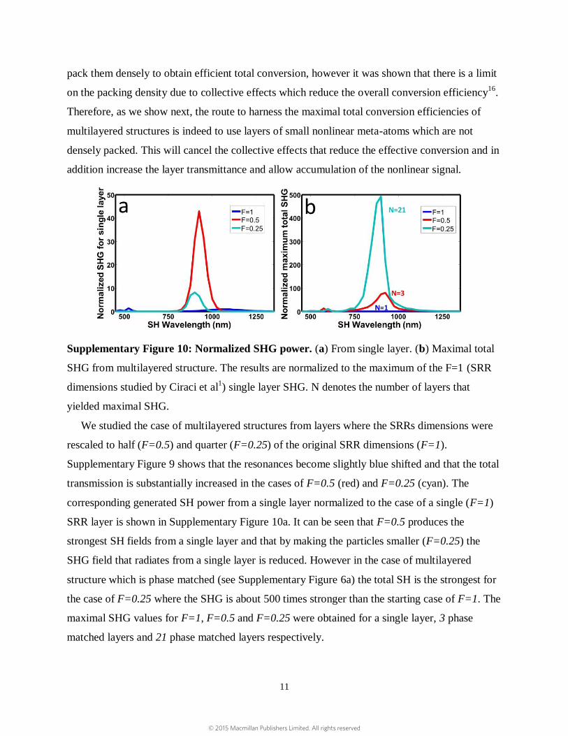
Supplementary Figure 10: Normalized SHG power. (a) From single layer. (b) Maximal total
SHG from multilayered structure. The results are normalized to the maximum of the F=1 (SRR
dimensions studied by Ciraci et al1) single layer SHG. N denotes the number of layers that
yielded maximal SHG.
We studied the case of multilayered structures from layers where the SRRs dimensions were
rescaled to half (F=0.5) and quarter (F=0.25) of the original SRR dimensions (F=1).
Supplementary Figure 9 shows that the resonances become slightly blue shifted and that the total
transmission is substantially increased in the cases of F=0.5 (red) and F=0.25 (cyan). The
corresponding generated SH power from a single layer normalized to the case of a single (F=1)
SRR layer is shown in Supplementary Figure 10a. It can be seen that F=0.5 produces the
strongest SH fields from a single layer and that by making the particles smaller (F=0.25) the
SHG field that radiates from a single layer is reduced. However in the case of multilayered
structure which is phase matched (see Supplementary Figure 6a) the total SH is the strongest for
the case of F=0.25 where the SHG is about 500 times stronger than the starting case of F=1. The
maximal SHG values for F=1, F=0.5 and F=0.25 were obtained for a single layer, 3 phase
matched layers and 21 phase matched layers respectively.
© 2015 Macmillan Publishers Limited. All rights reserved

12
The simulated accumulation through the multilayered structure for F=0.25 is shown in
Supplementary Figure 11. The FH wavelength in the simulation was 1750 nm and Lc in the silica
matrix was 83 m. In the case of perfect phase matching the layers were placed at Lc separations.
In the case of non-phase matched and QPM cases the layers were placed in separations of Lc/8 in
uniform orientations and in alternating orientation respectively (alternating orientation
configuration is shown in Supplementary Figure 6c). The buildup of the SH waves with respect
to the number of layers resembles the known dynamics for perfect phase matching, QPM and
non-phase matched nonlinear interactions17
with added losses due to the partial transmittance.
Supplementary Figure 11b shows the SH field accumulation in perfect phase matching and QPM
stacked layer configurations (shown as configurations a b and c in Supplementary Figure 6). It
can be seen that in the QPM case the maximal total SHG is slightly reduced in comparison to the
perfect phase matched cases, however it’s maximum is obtained much faster which means that it
can be used to significantly reduce the total dimensions of the converting device.
Supplementary Figure 11: Phase matching with multilayered metamaterials. Total SHG
output field for F=0.25 (a) as function of number of layers and (b) as function of propagation
length in the structure.
From the obtained results we can understand that multilayered structures can be used to
significantly enhance the efficiency from nonlinear metamaterials. The best efficiency will be
achieved for small particles which are not too closely packed to avoid collective effects. QPM by
alternating the orientation of the structures is highly important since it allows getting efficient
interaction in much shorter lengths compared to placing layers at Lc or Lc/2. We believe that this
© 2015 Macmillan Publishers Limited. All rights reserved
13
study gives the motivation to use QPM in three-dimensional metamaterials and opens many new
directions to study nonlinear dynamics in three-dimensional metamaterials which need further
investigations and are out of the scope of this work.
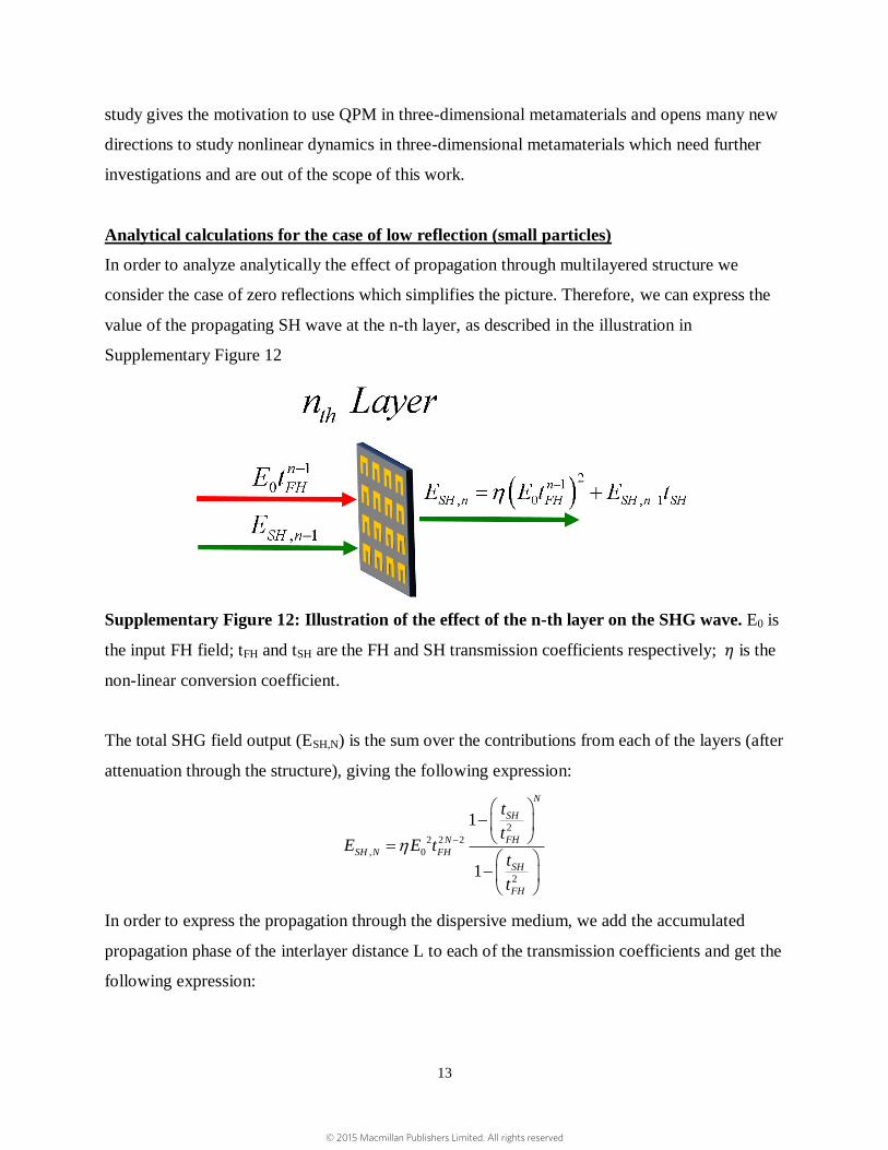
Analytical calculations for the case of low reflection (small particles)
In order to analyze analytically the effect of propagation through multilayered structure we
consider the case of zero reflections which simplifies the picture. Therefore, we can express the
value of the propagating SH wave at the n-th layer, as described in the illustration in
Supplementary Figure 12
Supplementary Figure 12: Illustration of the effect of the n-th layer on the SHG wave. E0 is
the input FH field; tFH and tSH are the FH and SH transmission coefficients respectively; 𝜂 is the
non-linear conversion coefficient.
The total SHG field output (ESH,N) is the sum over the contributions from each of the layers (after
attenuation through the structure), giving the following expression:
2
2 2 2
, 0
2
1
1
N
SH
FHN
SH N FH
SH
FH
t
tE E t
t
t
In order to express the propagation through the dispersive medium, we add the accumulated
propagation phase of the interlayer distance L to each of the transmission coefficients and get the
following expression:
© 2015 Macmillan Publishers Limited. All rights reserved
14
2
2 2 2 22
, 0
2
1 e
e
1 e
FH
N
iN kLSH
N i N k L FH
SH N FH
i kLSH
FH
t
tE E t
t
t
Where
2SH FHk k k
As shown by the formula for the total SHG field output, and as described above, the interlayer
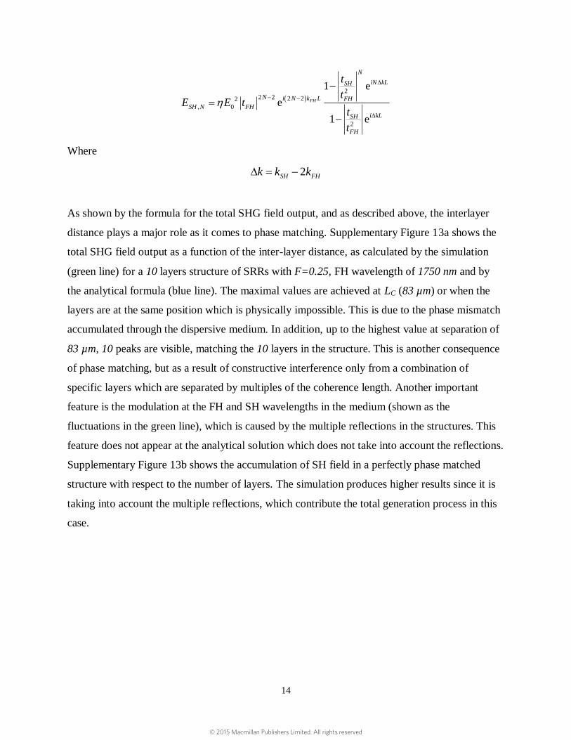
distance plays a major role as it comes to phase matching. Supplementary Figure 13a shows the
total SHG field output as a function of the inter-layer distance, as calculated by the simulation
(green line) for a 10 layers structure of SRRs with F=0.25, FH wavelength of 1750 nm and by
the analytical formula (blue line). The maximal values are achieved at LC (83 µm) or when the
layers are at the same position which is physically impossible. This is due to the phase mismatch
accumulated through the dispersive medium. In addition, up to the highest value at separation of
83 µm, 10 peaks are visible, matching the 10 layers in the structure. This is another consequence
of phase matching, but as a result of constructive interference only from a combination of
specific layers which are separated by multiples of the coherence length. Another important
feature is the modulation at the FH and SH wavelengths in the medium (shown as the
fluctuations in the green line), which is caused by the multiple reflections in the structures. This
feature does not appear at the analytical solution which does not take into account the reflections.
Supplementary Figure 13b shows the accumulation of SH field in a perfectly phase matched
structure with respect to the number of layers. The simulation produces higher results since it is
taking into account the multiple reflections, which contribute the total generation process in this
case.
© 2015 Macmillan Publishers Limited. All rights reserved
15
Supplementary Figure 13: Comparison between simulation and analytical results for small
particles (F=0.25) (a) Total SHG dependence of a structure of 10 layers of SRRs with uniform
orientations on inter-layer distance. (b) SH field accumulation Vs. layer number in a perfect
phase matched structure.
Supplementary Section V: Illustrations of the SH radiation emitted from the NLMPC
based FZP
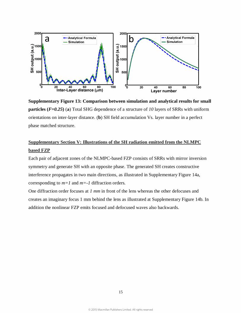
Each pair of adjacent zones of the NLMPC-based FZP consists of SRRs with mirror inversion
symmetry and generate SH with an opposite phase. The generated SH creates constructive
interference propagates in two main directions, as illustrated in Supplementary Figure 14a,
corresponding to m=1 and m=-1 diffraction orders.
One diffraction order focuses at 1 mm in front of the lens whereas the other defocuses and
creates an imaginary focus 1 mm behind the lens as illustrated at Supplementary Figure 14b. In
addition the nonlinear FZP emits focused and defocused waves also backwards.
© 2015 Macmillan Publishers Limited. All rights reserved
16
Supplementary Figure 14: Emission of nonlinear FZP (a) Simulation of far-field SH emission
from a one-dimensional NLMPC on glass. The asymmetry of emission is due to emission to air
on the right and glass on the left. (b) Illustration of the NLMPC-based FZP SH radiation pattern
showing forward and backward focusing and defocusing of nonlinear emission.
References:
1. Ciracì, C., Poutrina, E., Scalora, M. & Smith, D. R. Origin of second-harmonic generation
enhancement in optical split-ring resonators. Phys. Rev. B 85, 201403 (2012).
2. Scalora, M. et al. Second- and third-harmonic generation in metal-based structures. Phys.
Rev. A 82, 043828 (2010).
3. Berger, V. Nonlinear Photonic Crystals. Phys. Rev. Lett. 81, 4136–4139 (1998).
4. Arie, A. & Voloch, N. Periodic, quasi-periodic, and random quadratic nonlinear photonic
crystals. Laser Photon. Rev. 4, 355–373 (2010).
5. Sheng, Y., Kong, Q., Wang, W., Kalinowski, K. & Krolikowski, W. Theoretical
investigations of nonlinear Raman–Nath diffraction in the frequency doubling process. J.
Phys. B At. Mol. Opt. Phys. 45, 055401 (2012).
6. Soukoulis, C. M. & Wegener, M. Past achievements and future challenges in the
development of three-dimensional photonic metamaterials. Nat. Photonics 5, 523–530
(2011).
7. Armstrong, J., Bloembergen, N., Ducuing, J. & Pershan, P. Interactions between Light
Waves in a Nonlinear Dielectric. Phys. Rev. 127, 1918–1939 (1962).
© 2015 Macmillan Publishers Limited. All rights reserved
17
8. Fejer, M. M., Magel, G. A., Jundt, D. H. & Byer, R. L. Quasi-phase-matched second
harmonic generation: tuning and tolerances. IEEE J. Quantum Electron. 28, 2631–2654
(1992).
9. Ellenbogen, T., Dolev, I. & Arie, A. Mode conversion in quadratic nonlinear crystals. Opt.
Lett. 33, 1207–9 (2008).
10. Ellenbogen, T., Voloch-Bloch, N., Ganany-Padowicz, A. & Arie, A. Nonlinear generation
and manipulation of Airy beams. Nat. Photonics 3, 395–398 (2009).
11. Ellenbogen, T., Ganany-Padowicz, A. & Arie, A. Nonlinear photonic structures for all-
optical deflection. Opt. Express 16, 3077–82 (2008).
12. Tanzilli, S. et al. Highly efficient photon-pair source using periodically poled lithium
niobate waveguide. Electron. Lett. 37, 26 (2001).
13. Saleh, B. E. A. & Teich, M. C. in Fundam. Photonics 243–288 (Wiley, 2007).
14. Bass, M. et al. Handbook of Optics, Third Edition Volume IV: Optical Properties of
Materials, Nonlinear Optics, Quantum Optics (set): Optical Properties of Materials,
Nonlinear Optics, Quantum Optics (set). 1152 (McGraw Hill Professional, 2009).
15. Klein, M. W., Enkrich, C., Wegener, M. & Linden, S. Second-harmonic generation from
magnetic metamaterials. Science 313, 502–4 (2006).
16. Linden, S. et al. Collective Effects in Second-Harmonic Generation from Split-Ring-
Resonator Arrays. Phys. Rev. Lett. 109, 015502 (2012).
17. Boyd, R. W. Nonlinear Optics. Nonlinear Opt. 69–133 (Elsevier, 2008).
doi:10.1016/B978-0-12-369470-6.00002-2
© 2015 Macmillan Publishers Limited. All rights reserved