Controlling Criteria and Design Justification Process for ...
13
ENGINEERING DIRECTIVE Page 1 of 13 Patricia Leavenworth (signature on original) ____________________________________ CHIEF ENGINEER Controlling Criteria and Design Justification Process for MassDOT Highway Division Projects The purpose of this Engineering Directive is to indicate the controlling criteria and appropriate design guidance that shall be applied to MassDOT Highway Division projects, shown in Exhibit 1. This Directive updates MassDOT design criteria for pedestrian, bicycle, transit, and vehicle facilities and provides direction regarding the FHWA controlling criteria as presented in their Memorandum dated May 5, 2016. This Directive supersedes Engineering Directive E-14-006, dated December 19, 2014; updates Section 2.11 of the Project Development and Design Guide; and supports the MassDOT Healthy Transportation Policy Directive P-13-0001, dated September 9, 2013. This Directive applies to all projects not yet advertised for construction. Projects that have received 25% Project Approval as of December 31, 2019 are exempt from meeting the requirements of this Directive, unless directed otherwise by MassDOT on a case-by-case basis. The controlling criteria and processes contained herein apply to the projects listed in Exhibit 1. Exhibit 1 Applicable MassDOT Highway Division projects MassDOT Highway Division is the project proponent. MassDOT Highway Division is responsible for project funding (state or federal aid). MassDOT Highway Division controls the affected infrastructure (State Highway), including projects seeking Category II and III Highway Access Permits. The design guidance contained herein is intended to provide project proponents with sufficient flexibility to address the unique and diverse conditions encountered on the Commonwealth’s streets and highways. The specific criteria used for roadway and bridge design in Massachusetts vary based on the facility type and area type; these criteria are based on years of research and empirical data for safe and efficient movement of people. Departure from these criteria requires documentation to support the decision-making process. Number: E-20-001 Date: 01/02/20 Roadway and bridge projects advanced under programs, such as Chapter 90 and Massworks are not required to follow the process in this Directive; however, these projects should follow applicable design standards. (Refer to the requirements of the applicable program.)
Transcript of Controlling Criteria and Design Justification Process for ...

ENGINEERING DIRECTIVE
Page 1 of 13
Patricia Leavenworth (signature on original)____________________________________ CHIEF ENGINEER
Controlling Criteria and Design Justification Process for MassDOT Highway Division Projects
The purpose of this Engineering Directive is to indicate the controlling criteria and appropriate design guidance that shall be applied to MassDOT Highway Division projects, shown in Exhibit 1. This Directive updates MassDOT design criteria for pedestrian, bicycle, transit, and vehicle facilities and provides direction regarding the FHWA controlling criteria as presented in their Memorandum dated May 5, 2016. This Directive supersedes Engineering Directive E-14-006, dated December 19, 2014; updates Section 2.11 of the Project Development and Design Guide; and supports the MassDOT Healthy Transportation Policy Directive P-13-0001, dated September 9, 2013.
This Directive applies to all projects not yet advertised for construction. Projects that have received 25% Project Approval as of December 31, 2019 are exempt from meeting the requirements of this Directive, unless directed otherwise by MassDOT on a case-by-case basis.
The controlling criteria and processes contained herein apply to the projects listed in Exhibit 1.
Exhibit 1 Applicable MassDOT Highway Division projects MassDOT Highway Division is the project proponent. MassDOT Highway Division is responsible for project funding (state or federal aid). MassDOT Highway Division controls the affected infrastructure (State Highway), including projects seeking Category II and III Highway Access Permits. The design guidance contained herein is intended to provide project proponents with sufficient flexibility to address the unique and diverse conditions encountered on the Commonwealth’s streets and highways.
The specific criteria used for roadway and bridge design in Massachusetts vary based on the facility type and area type; these criteria are based on years of research and empirical data for safe and efficient movement of people. Departure from these criteria requires documentation to support the decision-making process.
Number: E-20-001 Date: 01/02/20
Roadway and bridge projects advanced under programs, such as Chapter 90 and Massworks are not required to follow the process in this Directive; however, these projects should follow applicable design standards. (Refer to the requirements of the applicable program.)

Page 2 of 13
MassDOT recognizes 14 controlling criteria. These criteria are:
1. Pedestrian Facilities 2. Bicycle Facilities 3. Transit Provisions 4. Ramp Length (for Roadways) 5. Design Speed 6. Design Loading Structural Capacity 7. Lane Width 8. Shoulder Width 9. Horizontal Curve Radius 10. Superelevation Rate 11. Stopping Sight Distance 12. Maximum Grade 13. Cross Slope 14. Vertical Clearance
Criteria 1-4 are referred to as the MassDOT Controlling Criteria. Criteria 5-14 are referred to as the FHWA Controlling Criteria. Criteria 1-3 are also referred to as the Complete Streets Criteria.
Definitions of the controlling criteria to be applied to MassDOT projects are contained in the most current editions of the guidance documents listed in Exhibit 2.
Exhibit 2 Applicable Design Guidance Documents
Author Guidance Document
AASHTO Guide for the Development of Bicycle Facilities AASHTO Guide for the Planning, Design, and Operation of Pedestrian Facilities AASHTO Guide on Geometric Design of Transit Facilities on Highways and Streets AASHTO A Guide on Achieving Flexibility in Highway Design AASHTO A Policy on Design Standards, Interstate System (“AASHTO Interstate”) AASHTO A Policy on Geometric Design of Highways and Streets (“Green Book”) FHWA Achieving Multimodal Networks FHWA Small Town and Rural Multimodal Networks FHWA Update to Controlling Criteria
MassDOT Project Development and Design Guide (“PDDG”) MassDOT Separated Bike Lane Planning and Design Guide
NACTO Urban Streets Design Guide (“NACTO”) NACTO Urban Bikeway Design Guide NACTO Transit Street Design Guide
Every reasonable effort should be made to design projects within the ranges of standards provided in these guidance documents.

Page 3 of 13
Design Justification Workbook
The Designer shall prepare and submit a Design Justification Workbook at the 25 Percent Design stage for all projects, except as described below. The latest version of the Workbook can be downloaded from http://www.mass.gov/. The Design Justification Workbook provides a uniform method for considering and evaluating controlling criteria and for documenting design decisions and shall be completed in its entirety by the Designer.
The following types of projects are exempt from the need to prepare and submit a Design Justification Workbook:
• Pavement preservation activities: * o Crack sealing o Fog sealing o Chip sealing o Rubber chip sealing
• Bridge preservation/maintenance treatments such as joint repair, deck repair, superstructure repair, and substructure repair *
• Non-roadway maintenance actions such as mowing, catch basin cleaning, or street sweeping
• Drainage only • Noise barrier only • Guardrail only • Lighting only • Traffic signal equipment only • Signing only • Landscape only • Vertical construction projects • Non-vehicular access permits • Minor vehicle access permits (Category I)
* In order to claim these exemptions, the purpose and need of the project must be solely to maintain the roadway surface or bridge structure, and the crash history must not indicate any apparent geometric deficiency.
In addition to the project type exemptions provided above, some of the controlling criteria are not applicable to every project that requires a Design Justification Workbook. Exhibit 3 lists all projects where a subset of the controlling criteria would not require formal approval if the criteria are not met.

Page 4 of 13
Exhibit 3 Exemptions from the Need to Comply with Certain Controlling Criteria
Project Work Type Pedestrian Facilities
Bicycle Facilities
Transit Provisions
Ramp Length
FHWA Controlling
Criteria Pavement preservation activities: *
• Microsurfacing • Cape seal • Ultra thin bonded wearing • Cold-in-place recycling • Hot-in-place recycling • Level and overlay • Mill and overlay • Full-depth reclamation
X X
Pavement marking only X X X X Sidewalk and/or curb ramps only X X X Work on facilities where pedestrians are not legally allowed X X Work on facilities where bicyclists are not legally allowed X Work on side streets where pedestrian facilities are not already present within 1500’ ** X
Work on side streets where bicycle facilities are not already present within 1500’ ** X
Work on roads with a functional classification of “local” X Work on facilities with no existing or proposed RTA or MBTA service X Projects designed under the Bridge R&R Program for Non-NHS Bridges (P-92-010) *** X X
Isolated single intersection safety improvement projects (with minimal work on approach roadways) X X
Categories of work marked with “X” do not require formal approval by the Chief Engineer, Secretary of Transportation, and/or FHWA (or their designees) in the event the applicable controlling criteria is not met.
*In order to claim this exemption, the purpose and need of the project must be solely to maintain the roadway surface, and the crash history must not indicate any apparent geometric deficiency.
**Refer to Figures 1 and 2.
***On rural local or rural collector roadways, these projects are also exempt from Pedestrian Facilities if no pedestrian facilities currently exist on the bridge or the approaches.

Page 5 of 13
The Design Justification Workbook contains entries for all 14 controlling criteria. Designers must fill out the workbook in its entirety regardless of whether exemptions from the need to comply with certain controlling criteria exist (as indicated in Exhibit 3).
If the designer cannot meet the standard for any criterion marked with a checkmark in Exhibit 4, the Design Justification Workbook shall require formal approval by the entities in Exhibit 5.
Exhibit 4 MassDOT and FHWA Controlling Criteria
Design Speed
Controlling Criteria <50 mph Facilities
>50 mph Facilities (1)
Stat
e-O
nly 1 Pedestrian Facilities ✔ ✔
2 Bicycle Facilities ✔ ✔ 3 Transit Provisions ✔ ✔ 4 Ramp Length (for Roadways) ✔ ✔
FHW
A &
Sta
te
5 Design Speed ✔ ✔ 6 Design Loading Structural Capacity ✔ ✔ 7 Lane Width ✔(2) ✔ 8 Shoulder Width ✔(2) ✔ 9 Horizontal Curve Radius ✔ 10 Superelevation Rate ✔ 11 Stopping Sight Distance ✔ 12 Maximum Grade ✔ 13 Cross Slope ✔ 14 Vertical Clearance ✔
(1) Includes any Interstate highways and other freeways regardless of speed. (2) These criteria are only reviewed and approved by MassDOT.
The Design Justification Workbook shall be prepared by the Designer and forwarded to the Project Manager as part of the 25 Percent Design submission; or, for permit projects, as part of the permit application.
Upon receipt of a Design Justification Workbook that requires approval of a substandard design element, the Project Manager shall forward a copy to the Chair of the Design Justification Review Committee and internal reviewers; the Workbook may require further signoff by the Chief Engineer, Secretary of Transportation, and/or the FHWA (or their designees).
MassDOT convenes a review committee responsible for tracking and reporting on all Design Justification issues, and for ensuring consistency in the application of design standards and in the documentation of design justifications. The Review Committee does not approve or reject workbooks.
Page 6 of 13
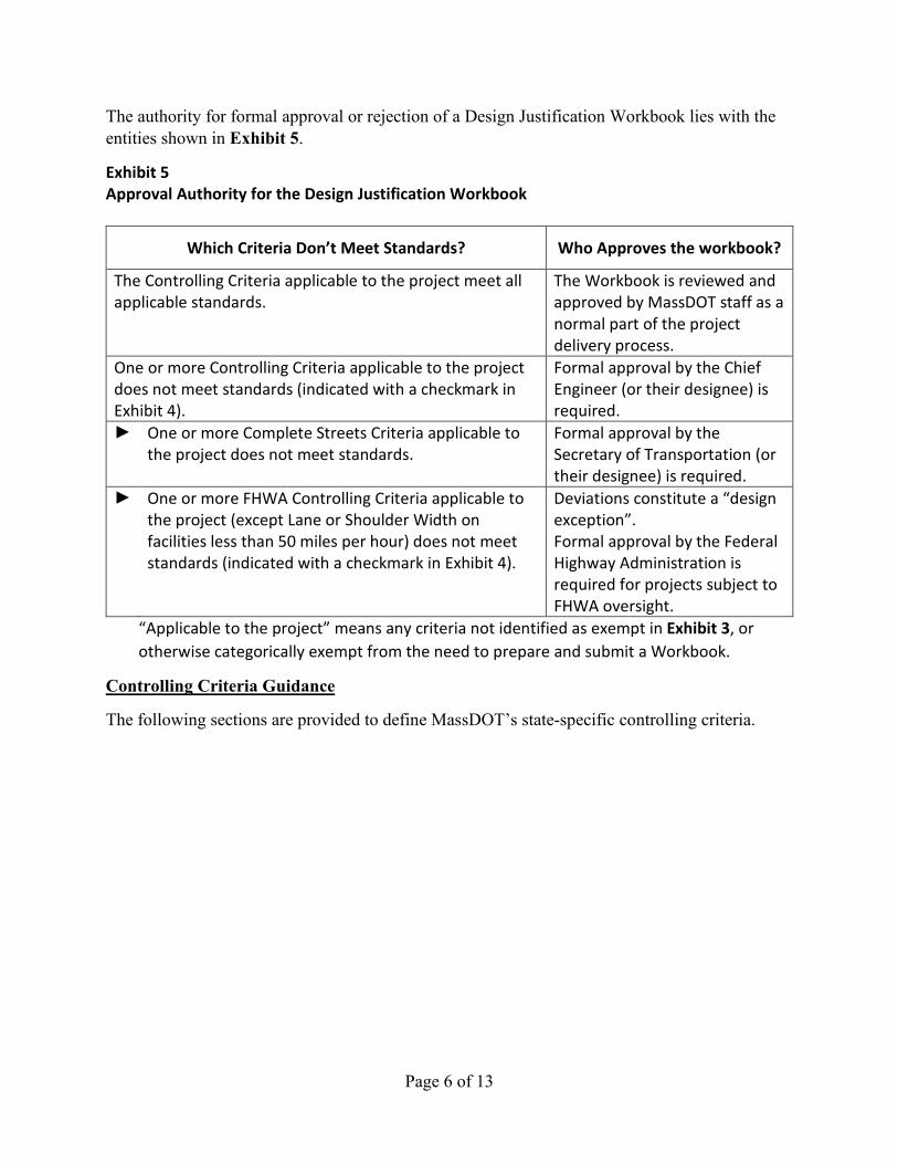
The authority for formal approval or rejection of a Design Justification Workbook lies with the entities shown in Exhibit 5.
Exhibit 5 Approval Authority for the Design Justification Workbook
Which Criteria Don’t Meet Standards? Who Approves the workbook?
The Controlling Criteria applicable to the project meet all applicable standards.
The Workbook is reviewed and approved by MassDOT staff as a normal part of the project delivery process.
One or more Controlling Criteria applicable to the project does not meet standards (indicated with a checkmark in Exhibit 4).
Formal approval by the Chief Engineer (or their designee) is required.
► One or more Complete Streets Criteria applicable to the project does not meet standards.
Formal approval by the Secretary of Transportation (or their designee) is required.
► One or more FHWA Controlling Criteria applicable to the project (except Lane or Shoulder Width on facilities less than 50 miles per hour) does not meet standards (indicated with a checkmark in Exhibit 4).
Deviations constitute a “design exception”. Formal approval by the Federal Highway Administration is required for projects subject to FHWA oversight.
“Applicable to the project” means any criteria not identified as exempt in Exhibit 3, or otherwise categorically exempt from the need to prepare and submit a Workbook.
Controlling Criteria Guidance
The following sections are provided to define MassDOT’s state-specific controlling criteria.

Page 7 of 13
Pedestrian Facilities
MassDOT is committed to providing facilities that are accessible to all users in accordance with all state and federal regulations. State regulations are issued by the Massachusetts Architectural Access Board (AAB) under 521 CMR. Federal regulations are issued by the United States Department of Justice (DOJ) under the 2010 ADA Standards for Accessible Design and the United States Department of Transportation (USDOT) under the 2006 ADA Standards for Transportation Facilities. It is recognized that full compliance with these regulations may not be feasible in all situations based on existing or latent field conditions. The Designer may request relief from State requirements as noted in 521 CMR 4.1, Variances; however, MassDOT is not involved in the approval or rejection of variances. Variance approval is considered “due diligence” and does not necessarily guarantee federal consent.
Definitions:
Pedestrian Facilities shall be designed in accordance with Chapters 5, 6, and 11 of the PDDG; Engineering Directives E-12-005 and E-12-007; and the AASHTO Guide for the Planning, Design, and Operation of Pedestrian Facilities.
Urbanized areas and urban clusters are as defined by the latest version of the “MassDOT Urban Boundaries” map, published by the MassDOT Office of Transportation Planning and available through GeoDOT.
Rural villages are defined in Section 3.2.1 of the PDDG.
Pedestrian facilities may include sidewalks, shared-use paths, or side paths.
Requirements:
Pedestrian facilities shall be provided on both sides of a roadway if any of the following apply:
• For all roadways in urbanized areas, urban clusters, or rural villages where pedestrians are legally allowed
• For all bridge projects where pedestrians are legally allowed including the roadway underneath the bridge.
• For all roadways with a High Potential for Walkable Trips, as defined in the latest version of the Massachusetts Pedestrian Transportation Plan
The minimum pedestrian facility width is 5’-0”. The minimum width of a pedestrian facility is exclusive of any curb width or buffer area. Other than shared-use paths and side paths, any pedestrian facilities shall be exclusive of any width intended for bicycle travel.
Marked crosswalks shall be provided across every leg of a signalized intersection where sidewalks are present and/or proposed.
Marked crosswalks shall be provided at existing crosswalks, regardless of the existence of any sidewalk(s).
Page 8 of 13
Bicycle Facilities
Definitions:
Bicycle Facilities shall be designed in accordance with Chapter 5 and 11 of the PDDG, the AASHTO Guide for the Development of Bicycle Facilities, MassDOT’s Separated Bike Lane Guide, and the NACTO Urban Bikeway Design Guide.
Bicycle facilities may include shared-use paths, side paths, separated bicycle lanes, buffered bicycle lanes, bicycle lanes, or paved outside shoulders. Facilities may provide service in a single direction of travel (“uni-directional”) or two directions of travel (“bi-directional”).
Requirements:
Bicycle facilities shall be provided and shall provide service for each direction of vehicular travel for all roadways where bicycles are legally allowed, except roadways classified as local.
The bicycle facility shall be a shared-use path, side path, separated bicycle lane, or buffered bicycle lane if any of the following apply:
• For all roadways with a posted (or statutory) speed limit greater than or equal to 40 miles per hour
• For all roadways with a volume greater than or equal to 10,000 vehicles per day • For all roadways at locations with more than one travel lane in a single direction • For all intersections with more than one travel lane in a single direction • For all roadways classified as a corridor with a High Potential for Everyday
Biking as defined in the Massachusetts Bicycle Transportation Plan
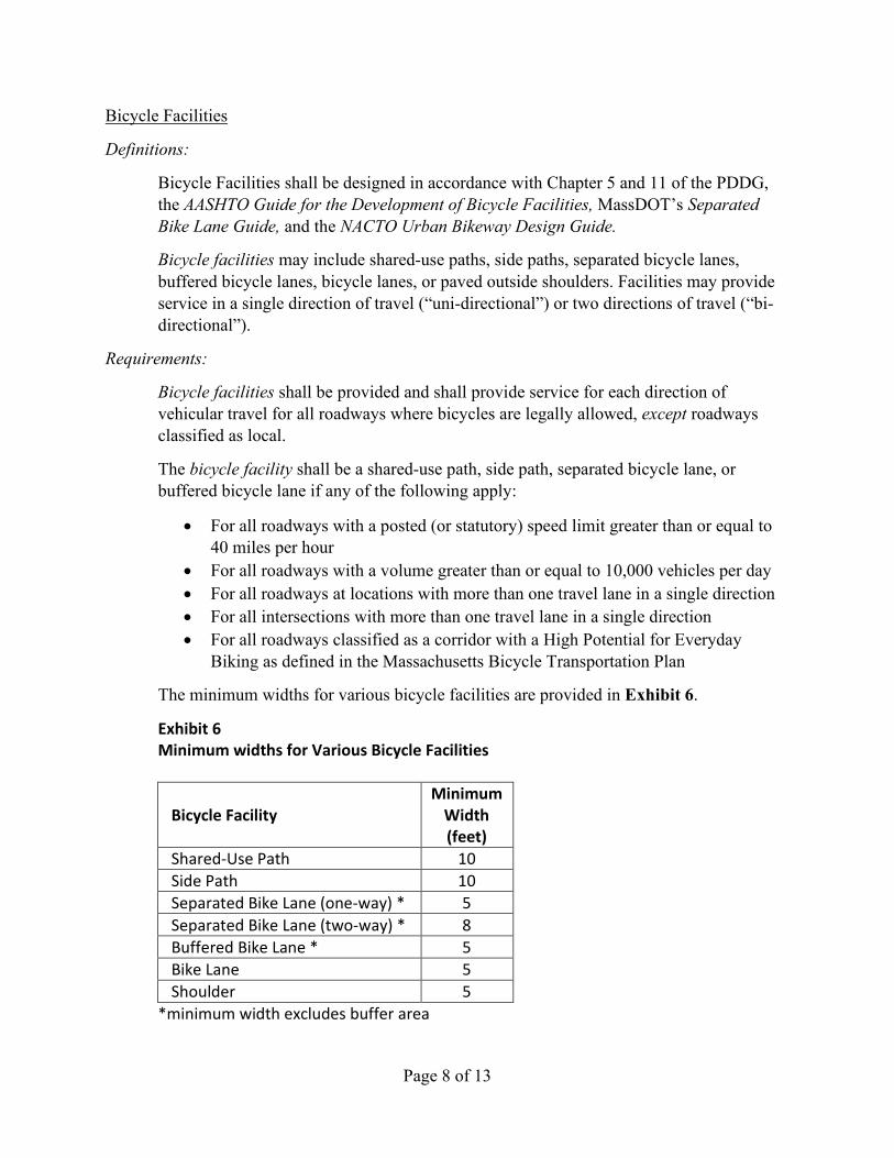
The minimum widths for various bicycle facilities are provided in Exhibit 6.
Exhibit 6 Minimum widths for Various Bicycle Facilities
Bicycle Facility Minimum
Width (feet)
Shared-Use Path 10 Side Path 10 Separated Bike Lane (one-way) * 5 Separated Bike Lane (two-way) * 8 Buffered Bike Lane * 5 Bike Lane 5 Shoulder 5
*minimum width excludes buffer area

Page 9 of 13
Transit Provisions
Definitions:
Transit Provisions shall be designed in accordance with Chapters 5 and 6 of the MassDOT Project Development Design Guide and the AASHTO Guide for Geometric Design of Transit Facilities on Highways and Streets.
For the purposes of this criterion, a transit route is any fixed-route bus, shuttle, streetcar, or trolley service owned or operated by a Regional Transit Authority (RTA), the Massachusetts Bay Transportation Authority (MBTA), or other public agency or state authority.
For the purposes of this criterion, a transit stop is any permanent location used for the boarding or alighting of passengers on a transit route; or, any permanent facility accepting or discharging passengers on intercity rail, regional rail, commuter rail, subways, streetcars, trolleys, or other fixed-guideway transit systems, regardless of owner or operator.
For the purposes of this criterion, a transit priority treatment is considered to be any means to improve transit operations, including, but not limited to, queue jumps, transit signal priority, and exclusive transit lanes.
Requirements:
For all projects that are located within the service district of an RTA or the MBTA and an existing or proposed transit route (considering both railroads and bus service) and containing facilities where pedestrians or bicyclists are legally allowed, the Designer shall submit a set of 25 Percent Design plans to the owner of the service and shall invite the owner to any planning or scoping meetings, as required.
Crosswalks or other means of facilitating accessible pedestrian access shall be provided between both sides of a roadway within 250 feet of existing or proposed transit stops.
A shelter or bench shall be provided at all transit stops with 100 or more boardings per day.
Transit priority treatments shall be provided along transit routes with headways of 15 minutes or less.
Page 10 of 13
Ramp Length (for Roadways)
Definitions:
Ramps (for roadways) are defined as any type, arrangement, or size of turning roadways that connect two or more legs at an interchange.
Requirements:
These Requirements shall be met in the following cases:
• Construction of a new ramp. • Major reconstruction/reconfiguration of an existing ramp.
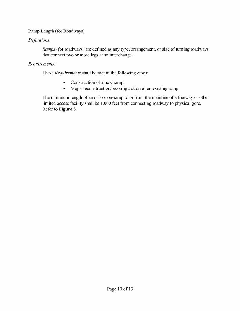
The minimum length of an off- or on-ramp to or from the mainline of a freeway or other limited access facility shall be 1,000 feet from connecting roadway to physical gore. Refer to Figure 3.

LIMIT OF WORK
1500'
EXIST. SIDEWALK
LIMIT OF WORK
If a side street has pedestrian facilities present within 1500-ft of the project
limits, a facility must be provided along the side street up to the limit of
work.
PROP. SIDEWALK
(For clarity, curb ramps and crosswalks are not shown on this figure; transitions between proposed and existing facilities are shown for illustrative purposes only and must be designed in accordance with applicable standards.)
FIGURE 1
Sidewalks
NOT TO SCALE

LIMIT OF WORKLIMIT OF WORK
1500'
PROP. BIKE LANE
1500'
EXIST. BIKE LANE
If a side street has bicycle facilities present within 1500-ft of the project limits, a facility must be provided along the side street up to the limit of work.
(For clarity, transitions between proposed and existing facilities are shown for illustrative purposes only and must be designed in accordance with applicable standards.)
FIGURE 2
Bike Lanes
NOT TO SCALE

R
a
m
p
L
e
n
g
t
h
Ram
p Length
Physical Gore
Physical Gore
Stop Bar
Edge of Connecting
Roadway
FIGURE 3
Ramp Length
NOT TO SCALE


![JUSTIFICATION TOOLKIT - ubmemeaensoprod.s3.amazonaws.com€¦ · F ORMA TTENDIN AC .PHAMAPACKEUROPE.COM JUSTIFICATION TOOLKIT Justification Letter Template Dear [Name]: I am writing](https://static.fdocuments.in/doc/165x107/5e176177a9d5b249e5069d31/justification-toolkit-ubmemeaensoprods3-f-orma-ttendin-ac-phamapackeuropecom.jpg)