Control Valves - clippard.com Full Line... · CHECK VALVES • Allow flow in one direction and...
17
CHECK VALVES • Allow flow in one direction and automatically prevent flow in the opposite direction • Durable brass body construction • Variety of porting options p. 116 EXHAUST VALVES • Compact, durable brass construction • #10-32, 1/8" NPT and 1/4" NPT p. 117 IN-LINE AIR CHOKES & VOLUME CHAMBERS • Provides time delay • Durable brass bodies p. 121 MUFFLERS • Recommended for controlling noise or speed • Durable brass bodies with porous sintered bronze air mesh p. 121 SHUTTLE VALVES • Allow flow from one inlet to outlet while blocking the other inlet • #10-32, 1/8" NPT and 1/4" NPT p. 127 PULSE VALVE • Available in #10-32, 1/8" NPT, or modular versions • Widely used in control circuits p. 128 Control Valves Control Valves 114
Transcript of Control Valves - clippard.com Full Line... · CHECK VALVES • Allow flow in one direction and...

CHECK VALVES
• Allow flow in one direction and automatically prevent flow in the opposite direction
• Durable brass body construction
• Variety of porting options
p. 116
EXHAUST VALVES
• Compact, durable brass construction
• #10-32, 1/8" NPT and 1/4" NPT
p. 117
IN-LINE AIR CHOKES & VOLUME CHAMBERS
• Provides time delay
• Durable brass bodies
p. 121
MUFFLERS
• Recommended for controlling noise or speed
• Durable brass bodies with porous sintered bronze air mesh
p. 121
SHUTTLE VALVES
• Allow flow from one inlet to outlet while blocking the other inlet
• #10-32, 1/8" NPT and 1/4" NPT
p. 127
PULSE VALVE
• Available in #10-32, 1/8" NPT, or modular versions
• Widely used in control circuits
p. 128
Control Valves
Control Valves114

877-245-6247 | clippard.com
FLOW CONTROLS
• Available in 4 styles
• Ideal for use with pneumatic cylinders
• Also used with air pilot valves for delay functions
pp. 118-120
GAUGES
• Display two pressure ranges
• Built-in pressure snubber
• Constructed with a steel case and plastic face
p. 121
NEEDLE VALVES
• Used to control the rate of flow in both directions
• Various port and needle configurations available
• Provide coarse or fine adjustment
pp. 122-123
PRESSURE REGULATORS
• Offered in either relieving or non-relieving versions
• Variety of adjustment options and mounting styles
pp. 124-126
SENSORS & AIR INDICATORS
• Non-contact proximity sensors
• Differential pressure sensors
• Whisker valves
• Single- and multi-pin air indicators
p. 128
SWITCHES
• Manual and pneumatic
• Convert air pressure to an electrical signal
p. 129
CON
TRO
L VA
LVES
Many items also available with metric ports. For more information, visit clippard.com/link/metric
877-245-6247 | clippard.com 115

Part No. Inlet Outlet Flow @ 50/100 psig Input Pressure Pressure to CrackMCV-1 #10-32M #10-32F MCV-1AA #10-32M #10-32M MCV-1AB #10-32F #10-32M MCV-1BB #10-32F #10-32F
MCV-2 #10-32F #10-32F 28 l/min @ 50 psig 100 psig 1 psig
MJCV-1 1/8” NPTF 1/8” NPTF MJCV-1AA 1/8” NPTM 1/8” NPTM MJCV-1AB 1/8” NPTF 1/8” NPTM MJCV-1BA 1/8” NPTM 1/8” NPTF GCV-4 1/4” NPTF 1/4” NPTF 39/2,000 l/min 300 psig 1 1/2 psigGCV-5 1/4” NPTF 1/4” NPTF 84/4,200 l/min
CHECK VALVES MCV, GCV & JPC SERIES
PILOT-OPERATED CHECK VALVES
Pilot-operated check valves work as standard check valves but can be opened with an air pilot signal to permit free flow in the normally “checked” direction. This provides the user with a reliable method to check flow in one direction with the ability to remotely signal a free flow through the valve. Clippard's JPC series all-in-one pilot-operated check valves are easy to connect and ideal for any circuit that might benefit from this useful function.
Medium Air, water, or oil Mount DirectTemp. Range 32 to 230°F Material ENP brass, anodized aluminum, stainless steel, nitrile seals
Medium AirMount Direct or in-lineTemp. Range 32 to 230°F
Not intended for pressure relief Arrow on valve indicates direction of flow
Min
imum
Pilo
t Pre
ssur
e (p
sig)
Supply Pressure (psig)
Minimum Pilot-to-Supply Pressure40
35
30
25
20
150 10 20 30 40 50 60 70 80 90 100
Flow
(l/m
in) (
Port
1 to
Por
t 2)
Supply Pressure (psig)
Flow-to-Supply Pressure800
600
400
200
0 10 20 30 40 50 60 70 80 90 100
JPC-3JPC-2
Multiple varieties of check valves permit flow in one direction only. Valve bodies provide in-line mounting, nitrile seals, and stainless steel springs (standard). The MCV-2 has a “duckbill” seal, the MCV-1 series has a brass poppet, and the MJCV-1 series has a Zytel 80G33 poppet.
6.5/325 l/min 300 psig 1/2 psig
20/1,000 l/min 1/2 psig300 psig(1,000 psig
hydraulic max.)
Min
imum
Pilo
t Pre
ssur
e (p
sig)
Supply Pressure (psig)
Minimum Pilot-to-Supply Pressure40
35
30
25
20
150 10 20 30 40 50 60 70 80 90 100
Flow
(l/m
in) (
Port
1 to
Por
t 2)
Supply Pressure (psig)
Flow-to-Supply Pressure800
600
400
200
0 10 20 30 40 50 60 70 80 90 100
JPC-3JPC-2
Contact Clippard for pilot-to-supply pressures above 100 psig
• High flow valve means low pressure drop
• Uses Clippard's superior poppet design
• #10-32 auxiliary port allows ease of plumbing
• Side port (port 2) rotates for ease of positioning
• Pressure range up to 300 psig (see charts below)
Part No. Cyl. Port Side Port Pilot Port
JPC-2NLN #10-32 M #10-32 F #10-32 F
JPC-2NPN 1/8” NPT #10-32 F #10-32 F
JPC-3FPN 1/8” NPT 1/8” NPT #10-32 F
JPC-3FPF 1/8” NPT 1/8” NPT 1/8” NPT
JPC-3FQF 1/4” NPT 1/8” NPT 1/8” NPT
Control Valves116
EXHAUST VALVES MEV, JEV & JLEV SERIES
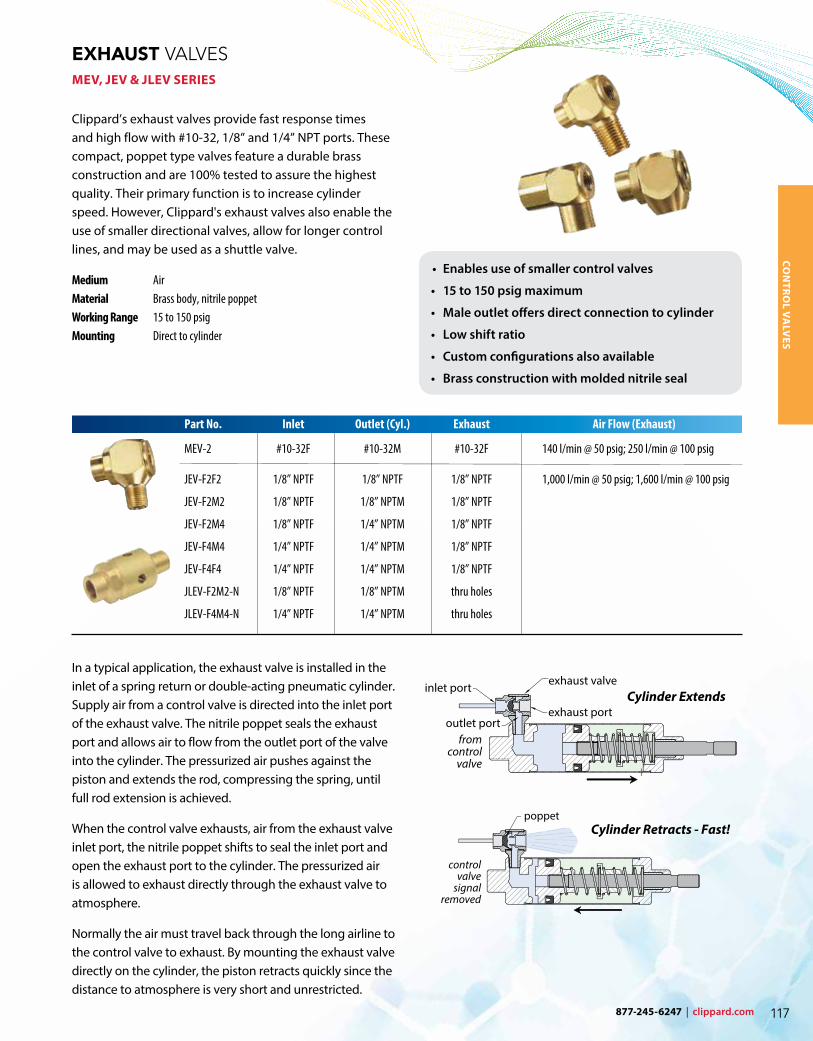
Clippard’s exhaust valves provide fast response times and high flow with #10-32, 1/8” and 1/4” NPT ports. These compact, poppet type valves feature a durable brass construction and are 100% tested to assure the highest quality. Their primary function is to increase cylinder speed. However, Clippard's exhaust valves also enable the use of smaller directional valves, allow for longer control lines, and may be used as a shuttle valve.
Medium AirMaterial Brass body, nitrile poppetWorking Range 15 to 150 psigMounting Direct to cylinder
Part No. Inlet Outlet (Cyl.) Exhaust Air Flow (Exhaust)
MEV-2 #10-32F #10-32M #10-32F 140 l/min @ 50 psig; 250 l/min @ 100 psig
JEV-F2F2 1/8” NPTF 1/8” NPTF 1/8” NPTF 1,000 l/min @ 50 psig; 1,600 l/min @ 100 psig
JEV-F2M2 1/8” NPTF 1/8” NPTM 1/8” NPTF
JEV-F2M4 1/8” NPTF 1/4” NPTM 1/8” NPTF
JEV-F4M4 1/4” NPTF 1/4” NPTM 1/8” NPTF
JEV-F4F4 1/4” NPTF 1/4” NPTM 1/8” NPTF
JLEV-F2M2-N 1/8” NPTF 1/8” NPTM thru holes
JLEV-F4M4-N 1/4” NPTF 1/4” NPTM thru holes
In a typical application, the exhaust valve is installed in the inlet of a spring return or double-acting pneumatic cylinder. Supply air from a control valve is directed into the inlet port of the exhaust valve. The nitrile poppet seals the exhaust port and allows air to flow from the outlet port of the valve into the cylinder. The pressurized air pushes against the piston and extends the rod, compressing the spring, until full rod extension is achieved.
When the control valve exhausts, air from the exhaust valve inlet port, the nitrile poppet shifts to seal the inlet port and open the exhaust port to the cylinder. The pressurized air is allowed to exhaust directly through the exhaust valve to atmosphere.
Normally the air must travel back through the long airline to the control valve to exhaust. By mounting the exhaust valve directly on the cylinder, the piston retracts quickly since the distance to atmosphere is very short and unrestricted.
Cylinder Extends
Cylinder Retracts - Fast!
• Enables use of smaller control valves
• 15 to 150 psig maximum
• Male outlet offers direct connection to cylinder
• Low shift ratio
• Custom configurations also available
• Brass construction with molded nitrile seal
CON
TRO
L VA
LVES
877-245-6247 | clippard.com 117
FLOW CONTROLS JFC & MFC SERIES
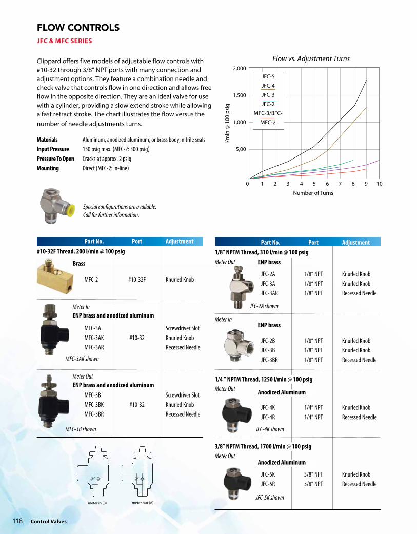
Clippard offers five models of adjustable flow controls with #10-32 through 3/8” NPT ports with many connection and adjustment options. They feature a combination needle and check valve that controls flow in one direction and allows free flow in the opposite direction. They are an ideal valve for use with a cylinder, providing a slow extend stroke while allowing a fast retract stroke. The chart illustrates the flow versus the number of needle adjustments turns.
Materials Aluminum, anodized aluminum, or brass body; nitrile sealsInput Pressure 150 psig max. (MFC-2: 300 psig)Pressure To Open Cracks at approx. 2 psigMounting Direct (MFC-2: in-line)
Number of Turns
l/min
@ 1
00 p
sig
JFC-5
JFC-4
JFC-3
JFC-2
MFC-3/BFC-
MFC-2
2,000
1,500
1,000
5,00
0 1 2 3 4 5 6 7 8 9 10
Flow vs. Adjustment Turns
#10-32F Thread, 200 l/min @ 100 psigPart No. Port Adjustment
MFC-2 #10-32F Knurled Knob
MFC-3A Screwdriver SlotMFC-3AK #10-32 Knurled KnobMFC-3AR Recessed Needle
MFC-3B Screwdriver SlotMFC-3BK #10-32 Knurled KnobMFC-3BR Recessed Needle
Special configurations are available. Call for further information.
MFC-3AK shown
MFC-3B shown JFC-4K shown
JFC-5K shown
JFC-2A shown
Brass
Meter InENP brass and anodized aluminum
Meter OutENP brass and anodized aluminum
ENP brass
ENP brass
Anodized Aluminum
Anodized Aluminum
Part No. Port Adjustment
JFC-2A 1/8” NPT Knurled KnobJFC-3A 1/8” NPT Knurled KnobJFC-3AR 1/8” NPT Recessed Needle
JFC-2B 1/8” NPT Knurled KnobJFC-3B 1/8” NPT Knurled KnobJFC-3BR 1/8” NPT Recessed Needle
JFC-4K 1/4” NPT Knurled KnobJFC-4R 1/4” NPT Recessed Needle
JFC-5K 3/8” NPT Knurled KnobJFC-5R 3/8” NPT Recessed Needle
1/8” NPTM Thread, 310 l/min @ 100 psigMeter Out
Meter In
1/4 ” NPTM Thread, 1250 l/min @ 100 psigMeter Out
3/8” NPTM Thread, 1700 l/min @ 100 psigMeter Out
mfc-3bk
meter in (B) meter out (A)
mfc-3ar
Control Valves118
877-245-6247 | clippard.com
FLOW CONTROLS PQ SERIES
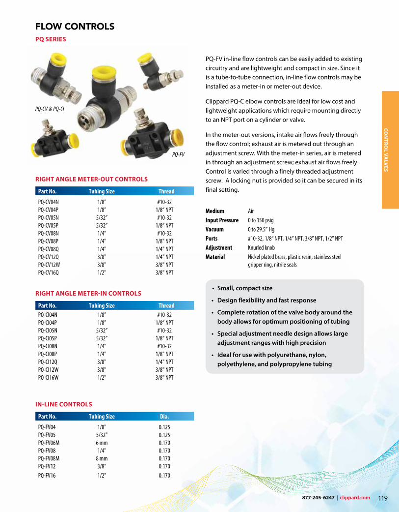
PQ-FV in-line flow controls can be easily added to existing circuitry and are lightweight and compact in size. Since it is a tube-to-tube connection, in-line flow controls may be installed as a meter-in or meter-out device.
Clippard PQ-C elbow controls are ideal for low cost and lightweight applications which require mounting directly to an NPT port on a cylinder or valve.
In the meter-out versions, intake air flows freely through the flow control; exhaust air is metered out through an adjustment screw. With the meter-in series, air is metered in through an adjustment screw; exhaust air flows freely. Control is varied through a finely threaded adjustment screw. A locking nut is provided so it can be secured in its final setting.
Medium AirInput Pressure 0 to 150 psig Vacuum 0 to 29.5” Hg Ports #10-32, 1/8” NPT, 1/4” NPT, 3/8” NPT, 1/2” NPTAdjustment Knurled knobMaterial Nickel plated brass, plastic resin, stainless steel gripper ring, nitrile seals
PQ-CV & PQ-CI
PQ-FV
• Small, compact size
• Design flexibility and fast response
• Complete rotation of the valve body around the body allows for optimum positioning of tubing
• Special adjustment needle design allows large adjustment ranges with high precision
• Ideal for use with polyurethane, nylon, polyethylene, and polypropylene tubing
RIGHT ANGLE METER-OUT CONTROLS
Part No. Tubing Size Thread
PQ-CV04N 1/8” #10-32PQ-CV04P 1/8” 1/8” NPTPQ-CV05N 5/32” #10-32PQ-CV05P 5/32” 1/8” NPTPQ-CV08N 1/4” #10-32 PQ-CV08P 1/4" 1/8" NPT PQ-CV08Q 1/4" 1/4" NPT PQ-CV12Q 3/8" 1/4" NPT PQ-CV12W 3/8" 3/8" NPT PQ-CV16Q 1/2" 3/8" NPT
RIGHT ANGLE METER-IN CONTROLS
Part No. Tubing Size ThreadPQ-CI04N 1/8” #10-32PQ-CI04P 1/8” 1/8” NPTPQ-CI05N 5/32” #10-32PQ-CI05P 5/32” 1/8” NPTPQ-CI08N 1/4” #10-32 PQ-CI08P 1/4" 1/8" NPT PQ-CI12Q 3/8" 1/4" NPT PQ-CI12W 3/8" 3/8" NPT PQ-CI16W 1/2" 3/8" NPT
IN-LINE CONTROLS
Part No. Tubing Size Dia.
PQ-FV04 1/8" 0.125 PQ-FV05 5/32" 0.125 PQ-FV06M 6 mm 0.170 PQ-FV08 1/4" 0.170 PQ-FV08M 8 mm 0.170PQ-FV12 3/8” 0.170PQ-FV16 1/2” 0.170
CON
TRO
L VA
LVES
877-245-6247 | clippard.com 119
FLOW CONTROLS BFC, BNV & BNM SERIES
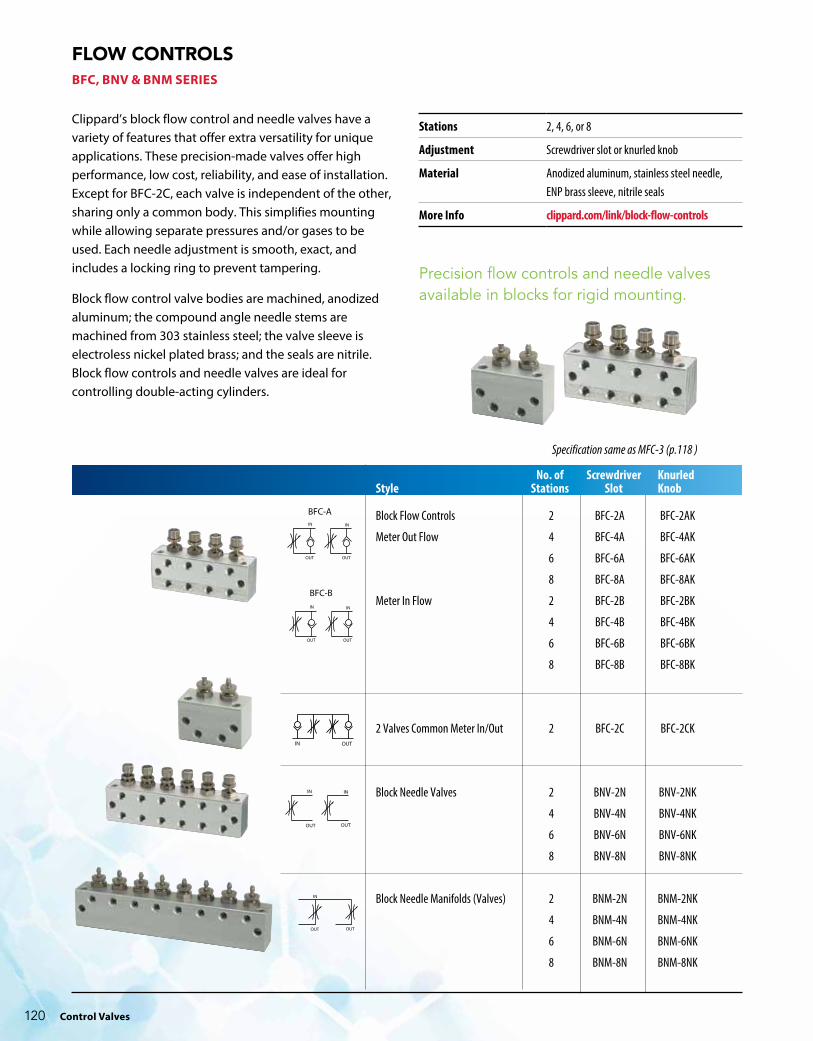
Clippard’s block flow control and needle valves have a variety of features that offer extra versatility for unique applications. These precision-made valves offer high performance, low cost, reliability, and ease of installation. Except for BFC-2C, each valve is independent of the other, sharing only a common body. This simplifies mounting while allowing separate pressures and/or gases to be used. Each needle adjustment is smooth, exact, and includes a locking ring to prevent tampering.
Block flow control valve bodies are machined, anodized aluminum; the compound angle needle stems are machined from 303 stainless steel; the valve sleeve is electroless nickel plated brass; and the seals are nitrile. Block flow controls and needle valves are ideal for controlling double-acting cylinders.
Specification same as MFC-3 (p.118 )
BFC-A
BFC-B
No. of Screwdriver KnurledStyle Stations Slot Knob
Block Flow Controls 2 BFC-2A BFC-2AK
Meter Out Flow 4 BFC-4A BFC-4AK
6 BFC-6A BFC-6AK
8 BFC-8A BFC-8AK
Meter In Flow 2 BFC-2B BFC-2BK
4 BFC-4B BFC-4BK
6 BFC-6B BFC-6BK
8 BFC-8B BFC-8BK
2 Valves Common Meter In/Out 2 BFC-2C BFC-2CK
Block Needle Valves 2 BNV-2N BNV-2NK
4 BNV-4N BNV-4NK
6 BNV-6N BNV-6NK
8 BNV-8N BNV-8NK
Block Needle Manifolds (Valves) 2 BNM-2N BNM-2NK
4 BNM-4N BNM-4NK
6 BNM-6N BNM-6NK
8 BNM-8N BNM-8NK
Stations 2, 4, 6, or 8
Adjustment Screwdriver slot or knurled knob
Material Anodized aluminum, stainless steel needle, ENP brass sleeve, nitrile seals
More Info clippard.com/link/block-flow-controls
Precision flow controls and needle valves available in blocks for rigid mounting.
Control Valves120

GAUGES, AIR CHOKES, VOLUME CHAMBERS & MUFFLERS
Medium: Air Material: BrassWorking Range: 0 to 300 psig max.
IN-LINE FIXED ORIFICE AIR CHOKESEach choke is calibrated for precise flow
IN-LINE VOLUME CHAMBERUsed for providing a time delay in pneumatic circuits.
Medium: AirMaterial: BrassInput Pressure: 150 psigMounting: Direct or in-line; mounting clamp with MAT-2.0 and MAT-4.0
SPEED CONTROL MUFFLERS
Speed control mufflers provide a variation of metering air flow at an acceptable sound level on valve exhaust ports. Knurled knob length based on minimum thread engagement. Solid brass body, sintered bronze muffler (40 micron).
Part No. Description
MAC-A Air Choke, 0.0135” HoleMAC-B Air Choke, 0.010” HoleMAC-C Air Choke, 0.0075” HoleMAC-D Air Choke, 0.006” Hole
The time delay of the PV-1, PV-1P and R-711 may be increased by adding standard Clippard volume chambers. The charts below show total time vs. volume for these combinations.
Time in SecondsVolume PV-1 R-711 0 0.042 0.117 0.1 0.074 0.180 0.25 0.124 0.245 0.5 0.210 0.350 1.0 0.390 0.450 1.2 0.580 0.700 2.0 0.760 1.000 2.4 0.950 1.300 3.6 1.200 1.900 4.0 1.500 N.R.
Volume Volume CU. IN. Chamber 0.1 MAT-.1 0.25 MAT-.25 0.50 MAT-.50 1.0 MAT-1.0 1.2 R-821 2.0 MAT-2.0 2.4 R-821 (2) 3.6 R-821 (3) 4.0 MAT-4.0
Part No. Description
MAT-(size) In-Line Volume Chamber, #10-32
Specify size per chart
Part No. Thread
SCM-P 1/8-27 NPTSCM-Q 1/4-18 NPTSCM-W 3/8-18 NPTSCM-Z 1/2-14 NPT
VACUUM GAUGE
Gauge measures pneumatic vacuum pressure; mounting bracket included.
Range Scale reading from 0 to 30” Hg and 0 to -1 bar
Construction Nickel-plated steel case. Dial shows two ranges: Hg (black) and bar (red). Built-in pressure snubber.
Ports Double threaded: O.D. male thread 1/8” NPT, I.D. tapped for #10-32 fitting
Part No. Description
VG-30 Vacuum Gauge
PRESSURE GAUGE
Gauge measures pneumatic system pressure; stud mounted.
Range Scale reading from 0 to 100 psig and 0 to 6.9 bar
Construction Steel case. Dial shows two ranges: psig (black) and bar (red). Built-in pressure snubber.
Ports Double threaded: O.D. male thread 1/8” NPT, I.D. tapped for #10-32 fitting
Part No. Description
PG-101-BKPG-101-NP
Pressure Gauge, Black CasePressure Gauge, Nickel-Plated
PRESSURE GAUGE
Gauge measures pneumatic system pressure; mounting bracket included.
Range Scale reading from 0 to 100 psig and 0 to 6.9 bar
Construction Steel case. Dial shows two ranges: psig (black) and bar (red). Built-in pressure snubber.
Ports Double threaded: O.D. male thread 1/8” NPT, I.D. tapped for #10-32 fitting
Part No. Description
PG-100 Pressure Gauge
CON
TRO
L VA
LVES
877-245-6247 | clippard.com 121
Part No. Needle Angle Inlet-Outlet Input Pressure Air Flow Mount Adjustment
MNV-1
15˚
#10-32-#10-32
2,000 psig max.85 l/min @ 50 psig; 170 l/min @ 100 psig
Direct
Screwdriver slot
MNV-1K Knurled knob
MNV-1P1/8" NPT-#10-32
Screwdriver slot
MNV-1KP Knurled knob
MNV-25˚ #10-32-#10-32 300 psig max.
28 l/min @ 50 psig; 71 l/min @ 100 psig
In-line (#15/32-32 thread)
Screwdriver slot
MNV-2K Knurled knob
MNV-3
3˚
#10-32-#10-32
2,000 psig max.71 l/min @ 50 psig; 140 l/min @ 100 psig
Direct
Screwdriver slot
MNV-3K Knurled knob
MNV-3P1/8" NPT-#10-32
Screwdriver slot
MNV-3KP Knurled knob
MNV-43˚ #10-32-#10-32 300 psig max. 140 l/min @ 100 psig Direct
Screwdriver slot
MNV-4K Knurled knob
MNV-4C3˚ Cartridge 150 psig max. 140 l/min @ 100 psig Cartridge
Screwdriver slot
MNV-4CK Knurled knob
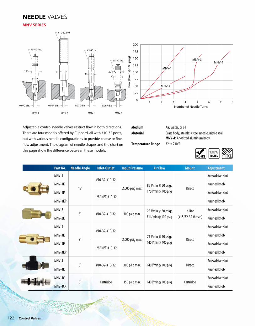
NEEDLE VALVES MNV SERIES
Adjustable control needle valves restrict flow in both directions.
There are four models offered by Clippard, all with #10-32 ports,
but with various needle configurations to provide coarse or fine
flow adjustment. The diagram of needle shapes and the chart on
this page show the difference between these models.
Number of Needle Turns
Flow
(l/m
in @
100
psi
g)
1 2 3 4 5 6 7 8
MNV-2
MNV-4MNV-3
MNV-1
200
175
150
125
100
75
50
25
0
Medium Air, water, or oil Material Brass body, stainless steel needle, nitrile seal MNV-4: Anodized aluminum bodyTemperature Range 32 to 230°F
Control Valves122
877-245-6247 | clippard.com
NEEDLE VALVES GNV SERIES
1 2 3 4 5 6 7 8Number of Turns
l/min
@ 1
00 p
sig
9 10
GNV-5GNV-4GNV-3
2,000
1,500
1,000
500
0
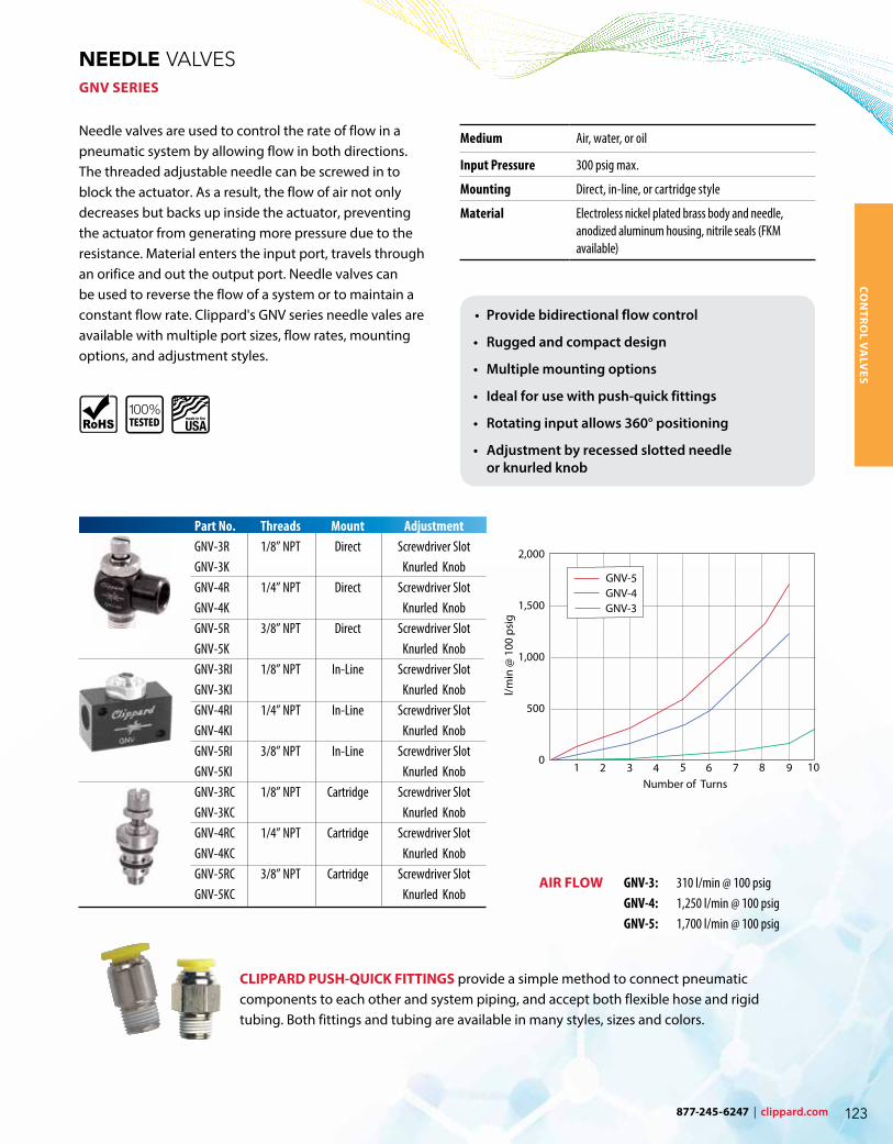
Needle valves are used to control the rate of flow in a pneumatic system by allowing flow in both directions. The threaded adjustable needle can be screwed in to block the actuator. As a result, the flow of air not only decreases but backs up inside the actuator, preventing the actuator from generating more pressure due to the resistance. Material enters the input port, travels through an orifice and out the output port. Needle valves can be used to reverse the flow of a system or to maintain a constant flow rate. Clippard's GNV series needle vales are available with multiple port sizes, flow rates, mounting options, and adjustment styles.
Part No. Threads Mount AdjustmentGNV-3R 1/8” NPT Direct Screwdriver SlotGNV-3K Knurled KnobGNV-4R 1/4” NPT Direct Screwdriver SlotGNV-4K Knurled KnobGNV-5R 3/8” NPT Direct Screwdriver SlotGNV-5K Knurled KnobGNV-3RI 1/8” NPT In-Line Screwdriver SlotGNV-3KI Knurled KnobGNV-4RI 1/4” NPT In-Line Screwdriver SlotGNV-4KI Knurled KnobGNV-5RI 3/8” NPT In-Line Screwdriver SlotGNV-5KI Knurled KnobGNV-3RC 1/8” NPT Cartridge Screwdriver SlotGNV-3KC Knurled KnobGNV-4RC 1/4” NPT Cartridge Screwdriver SlotGNV-4KC Knurled KnobGNV-5RC 3/8” NPT Cartridge Screwdriver SlotGNV-5KC Knurled Knob
CLIPPARD PUSH-QUICK FITTINGS provide a simple method to connect pneumatic components to each other and system piping, and accept both flexible hose and rigid tubing. Both fittings and tubing are available in many styles, sizes and colors.
GNV-3: 310 l/min @ 100 psigGNV-4: 1,250 l/min @ 100 psigGNV-5: 1,700 l/min @ 100 psig
AIR FLOW
• Provide bidirectional flow control
• Rugged and compact design
• Multiple mounting options
• Ideal for use with push-quick fittings
• Rotating input allows 360° positioning
• Adjustment by recessed slotted needle or knurled knob
Medium Air, water, or oil
Input Pressure 300 psig max.
Mounting Direct, in-line, or cartridge style
Material Electroless nickel plated brass body and needle, anodized aluminum housing, nitrile seals (FKM available)
CON
TRO
L VA
LVES
877-245-6247 | clippard.com 123
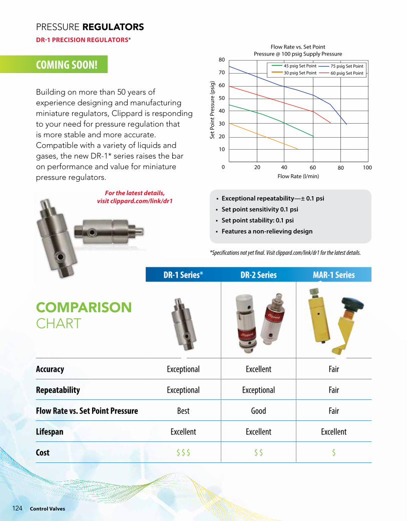
PRESSURE REGULATORS DR-1 PRECISION REGULATORS*
0 20 40 60 80Flow Rate (l/min)
Set P
oint
Pre
ssur
e (p
sig)
80
70
60
50
40
30
20
10
Flow Rate vs. Set PointPressure @ 100 psig Supply Pressure
100
45 psig Set Point30 psig Set Point
75 psig Set Point60 psig Set Point
Building on more than 50 years of experience designing and manufacturing miniature regulators, Clippard is responding to your need for pressure regulation that is more stable and more accurate. Compatible with a variety of liquids and gases, the new DR-1* series raises the bar on performance and value for miniature pressure regulators.
• Exceptional repeatability—± 0.1 psi
• Set point sensitivity 0.1 psi
• Set point stability: 0.1 psi
• Features a non-relieving design
COMING SOON!
For the latest details, visit clippard.com/link/dr1
DR-1 Series* DR-2 Series MAR-1 Series
COMPARISONCHART
Accuracy Exceptional Excellent Fair
Repeatability Exceptional Exceptional Fair
Flow Rate vs. Set Point Pressure Best Good Fair
Lifespan Excellent Excellent Excellent
Cost $ $ $ $ $ $
*Specifications not yet final. Visit clippard.com/link/dr1 for the latest details.
Control Valves124

877-245-6247 | clippard.com
ORDERING INFORMATION
PRESSURE REGULATORS DR-2 PRECISION REGULATORS
Flow Rate (l/min)
Set P
oint
Pre
ssur
e (p
sig)
80
70
60
50
40
30
20
10
0
Flow Rate vs. Set PointPressure @ 100 psig Supply Pressure
25 50 75 100 125 150 175 200
45 psig Set Point30 psig Set Point
75 psig Set Point60 psig Set Point
When Clippard invented miniature regulators in 1962, the MAR series (p. 126) became very popular as a simple, robust, cost-effective regulator with exceptionally long life. Today, the new DR-2 series maintains this same flow, performance, and durability while providing greater accuracy and repeatability in a sleek, compact package.
Regulators are offered in either relieving or non-relieving versions. The relieving design maintains a constant pressure output even when downstream conditions change, while non-relieving regulators do not automatically compensate for changes in downstream flow or pressure. There is no vent to atmosphere, as in a relieving type regulator, and the output pressure can increase due to a downstream event. Non-relieving versions can also accommodate compatible liquid applications.
Medium Relieving: AirNon-Relieving: Air, water, or oil
Input Pressure 300 psig max.
Repeatability ±0.1 psi typical (±0.15 psi max.)
Set Point Sensitivity 0.1 psi
Set Point Stability 0.1 psi
Temperature Range 32 to 230˚F
Mounting #15/32-32 thread; nuts & lockwashers furnished
Material Electroless nickel plated brass body, FKM seals, PFPE lube, stainless steel adjustment screw and spring
Adjustment An extended 0.25" shaft accepts an adjustment knob or furnished with an exposed screwdriver slot with micro-adjustment (32 pitch thread). Knobs ordered separately (#AK4-A)
More Details clippard.com/link/dr2
Not recommended for applications where accurate dead-end, no flow is required.
• Designed for applications where zero air consumption is required (non-bleed)
• Exceptional accuracy and repeatability
• Excellent corrosion resistance
• Relieving and non-relieving designs
• Manifold mount option
• Features non-rising internal adjustment
Consult Clippard for special configurations, preset options, or metric versions.
Inlet Outlet Base Part No.
#10-32 Female #10-32 Female DR-21/8” NPT Male #10-32 Female DR-2P#10-32 Male Manifold DR-2MCartridge Cartridge DR-2C1/8” NPT Male 1/8” NPT Female DR-2BP
Max. Pressure Range
(blank) 2 - 100 psig 1 0.5 - 10 psig 5 1 - 50 psig
Type
(blank) Relieving NR Non-Relieving
❑ ❑ - ❑
CON
TRO
L VA
LVES
Example Part Number:DR-2BP-5
877-245-6247 | clippard.com 125

PRESSURE REGULATORSMAR-1 REGULATORS
Since 1962, the MAR-1 has remained a popular choice as a simple, robust, cost-effective regulator in a small package with exceptionally long life. As regulator applications continue to increase, Clippard continues to meet the demand with a variety of new models, options and improvements.
Regulators are offered in either relieving or non-relieving versions. The relieving design maintains a constant pressure output even when downstream conditions change, while non-relieving regulators do not automatically compensate for changes in downstream flow or pressure. There is no vent to atmosphere, as in a relieving type regulator, and the output pressure can increase due to a downstream event. Non-relieving versions can accommodate compatible liquid applications.
Knurled Screwdriver Plastic Knob Slot Knob
Medium Relieving: AirNon-Relieving: Air, water, or oil
Input Pressure 300 psig max.
Air Flow 85 l/min @ 50 psig; 140 l/min @ 100 psig
Temperature Range 32 to 230˚F
Mounting #15/32-32 thread
Material Brass body, nitrile seals (FKM available), stainless steel stem and spring
Adjustment Knob with micro-adjustment (40 pitch thread); screwdriver slot and plastic adjustment also available
1C & 1CP: As plunger is depressed, pressure increases proportionally to the travel; when plunger is released, input is closed and output pressure is exhausted to atmosphere; 7/32" plunger travel
More Details clippard.com/link/mar
Inlet Outlet Base Part No.
#10-32 Female #10-32 Female MAR-11/8” NPT Male #10-32 Female MAR-1P#10-32 Male Manifold MAR-1MCartridge Cartridge MAR-1R1/8” NPT Male 1/8” NPT Female MAR-1BP
Adjustment
(blank) Knurled knobK Plastic knobF Screwdriver slotC Plunger style*
*Available in relieving version for MAR-1 and MAR-1P only
Max. Pressure Range
(blank) 10 to 100 psig2 10 to 20 psig3 10 to 30 psig4 10 to 40 psig5 10 to 50 psig6 10 to 60 psig7 10 to 70 psig
Type
(blank) Relieving NR Non-Relieving
NR not available on C & CP models
❑ ❑ ❑ - ❑
ORDERING INFORMATION
Example Part Number: MAR-1BP-2
FKM seals and electroless nickel plating
also available
Control Valves126

877-245-6247 | clippard.com
SHUTTLE VALVES MSV & JSV SERIES
These three shuttle valve models feature a shuttle that allows flow from one inlet to the outlet while blocking the other inlet. They may be mounted directly to valves and cylinders or in-line.
Medium Air, water, or oilInput Pressure MJSV/JSV: 300 psig max.; MSV: 250 psig max.Mounting Direct or in-lineExhaust Through port where pressure was last appliedMaterial Brass body, stainless steel shuttle, nitrile seal MJSV: Zytel® 80G33 shuttle; MSV: Brass shuttleNote Shuttle valves should not be used as a pressure selector
AC
B
mjsv-1
#10-32, 1/16” NPT, 1/8” NPT & 1/4” NPT Ports
Part No. Inlet 1 Inlet 2 Outlet Force to Shift Air Flow
MJSV-1 1/8” NPTF 1/8” NPTF 1/8” NPTF 1/2 psig 400 l/min @ 50 psig; 740 l/min @ 100 psig
JSV-2FPF 1/8” NPTF 1/8” NPTM 1/8” NPTF 1 psig 850 l/min @ 50 psig; 1,400 l/min @ 100 psigJSV-2PFF 1/8” NPTF 1/8” NPTF 1/8” NPTMJSV-2WFF 1/8” NPTF 1/8” NPTF 1/4” NPTMJSV-2WYY 1/4” NPTF 1/4” NPTF 1/4” NPTMJSV-2YFF 1/8” NPTF 1/8” NPTF 1/4” NPTFJSV-2YWY 1/4” NPTF 1/4” NPTM 1/4” NPTFJSV-2YYY 1/4” NPTF 1/4” NPTF 1/4” NPTF
MSV-1 #10-32F #10-32F #10-32M 1/2 psig 140 l/min @ 50 psig; 270 l/min @ 100 psigMSV-1FFF #10-32F #10-32F #10-32F
Custom SolutionsNeed a product that fits your application perfectly? Clippard can design or modify standard products to suit your exact needs.
Call 877-245-6247 today to discuss your application and specific requirements.
CON
TRO
L VA
LVES
877-245-6247 | clippard.com 127

A Normally-Open 3-Way valve that closes shortly after being pressurized and remains closed until supply pressure is exhausted and re-pressurized. Widely used in control circuits.
Time delay may be increased with Clippard volume chambers (not to exceed 3 cu. in.)
Medium AirInput Pressure 40 to 150 psig max.Mounting 1/8” NPT thread; nut furnishedVolume Chamber #10-32Operation Converts continuous supply of inlet air into pulse of approx. 100 msMaterial ENP brass body and poppet, nitrile seals, stainless steel spring2
3
pv-1
PULSE VALVES
Part No. Description
PV-1 Pulse Valve, #10-32PV-1P Pulse Valve, 1/8” NPT
2-WAY N-C WHISKER VALVESFor use with bleed pressure piloted control circuits. Whisker is easily replaceable and can be formed to different shapes.
1 2
mwv-1
Medium AirInput Pressure 150 psigAir Flow 28 l/min @ 50 psig; 42 l/min @ 100 psigForce for Stem Travel 1/4 oz. approx.Bleed To atmosphere around whisker stemWhisker Stainless steel, approx. 3” length.
Part No. Description
MWV-1 Normally-Closed Whisker Valve, #10-32MWV-1P Normally-Closed Whisker Valve, 1/8” NPT
Medium AirInput Pressure 4 to 10 psigProximity Distance 0.100” nominalOutput Signal Normal: -2” H2O @ 4 psig Supply Actuated: 7-1/2" H20Frequency Response 500 CPMAir Consumption 8.5 l/minSensing Capability Flat or curved surfaces with 1/8” min. radiusConnections #10-32 femaleMaterial Solid brass bright dipped
Part No. Description
1022 Non-Contact Air Limit Switch, #10-32
NON-CONTACT AIR PROXIMITY SWITCHNo moving parts—will sense any flat or curved object which presents a sensing surface of 1/4” or more to the sensing nozzle.
Medium AirInput Pressure 0.5 to 5 psigOutput -3” to 26” H2O @ 4 psigFrequency Response 1,000 cpmAir Consumption 7.1 l/min @ 4 psigSensing Capability Flat or curved surfaces with 1/32” min. radius. May be used for up to 4” gap with an additional auxiliary jetConnections #10-32 femaleMaterial Solid brass bright dipped
Part No. Description
1030 Non-Contact Gap Sensor, #10-32
NON-CONTACT GAP SENSORWill sense any flat or round object with a 1/32” min. radius. Produces positive signal when no object present; negative signal when an object interrupts its sensing system.
PULSE VALVES, SENSORS & AIR INDICATORS
MULTI-PIN AIR INDICATORPlunger type (when extended 7-pin color display signals “on”)
Part No. Description
IND-3-(color) Multi-Pin Air Indicator, #10-32IND-3P-(color) Multi-Pin Air Indicator, 1/8” NPT GN - ● WH - ● RD - ● YL - ●
Medium Air only Input Pressure 15 to150 psigResponse Approx. 10 ms @ 50 psigFiltration 40 micron recommendedPanel Thickness 3/16” max.Mounting IND-3: Panel mount, #15/32-32 nut & lockwasher provided; IND-3P: Direct mount, 1/8” NPT hole
Control Valves128
877-245-6247 | clippard.com
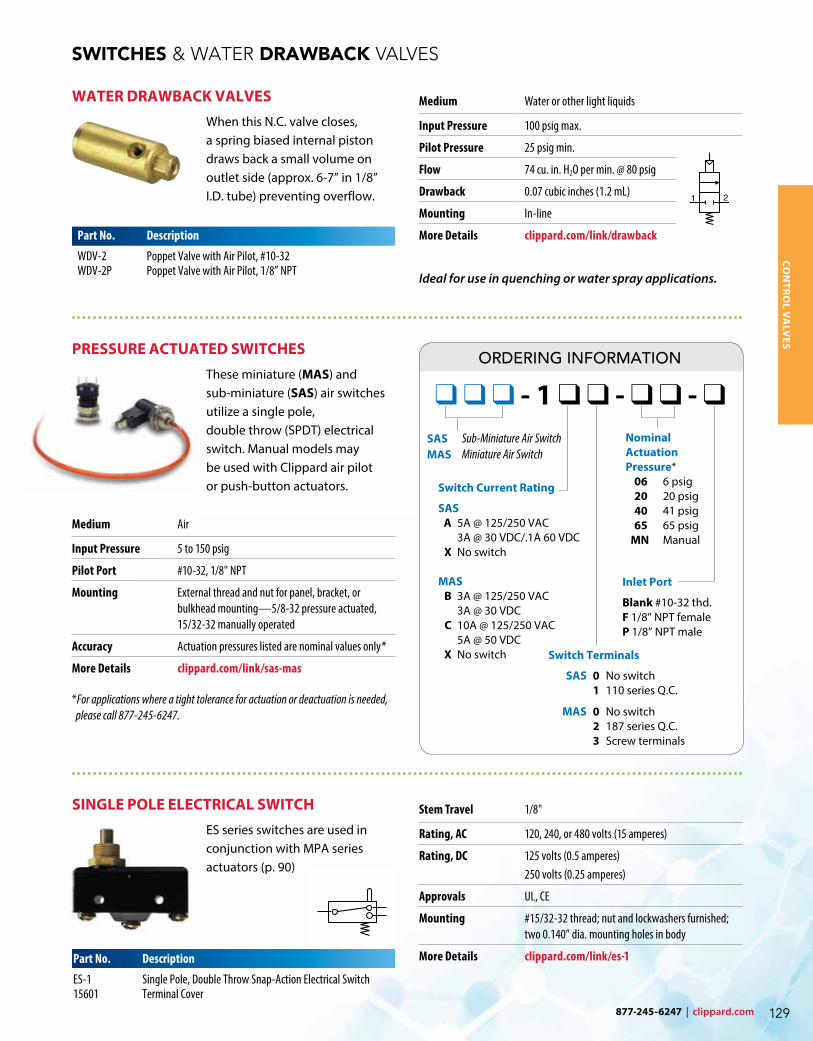
SWITCHES & WATER DRAWBACK VALVES
WATER DRAWBACK VALVESWhen this N.C. valve closes, a spring biased internal piston draws back a small volume on outlet side (approx. 6-7” in 1/8” I.D. tube) preventing overflow.
Part No. Description
WDV-2 Poppet Valve with Air Pilot, #10-32WDV-2P Poppet Valve with Air Pilot, 1/8” NPT
Medium Water or other light liquids
Input Pressure 100 psig max.
Pilot Pressure 25 psig min.
Flow 74 cu. in. H2O per min. @ 80 psig
Drawback 0.07 cubic inches (1.2 mL)
Mounting In-line
More Details clippard.com/link/drawback
Ideal for use in quenching or water spray applications.
1 2
wdv-2
SINGLE POLE ELECTRICAL SWITCHES series switches are used in conjunction with MPA series actuators (p. 90)
Stem Travel 1/8"
Rating, AC 120, 240, or 480 volts (15 amperes)
Rating, DC 125 volts (0.5 amperes) 250 volts (0.25 amperes)
Approvals UL, CE
Mounting #15/32-32 thread; nut and lockwashers furnished; two 0.140” dia. mounting holes in body
More Details clippard.com/link/es-1Part No. Description
ES-1 Single Pole, Double Throw Snap-Action Electrical Switch15601 Terminal Cover
Medium Air
Input Pressure 5 to 150 psig
Pilot Port #10-32, 1/8" NPT
Mounting External thread and nut for panel, bracket, or bulkhead mounting—5/8-32 pressure actuated, 15/32-32 manually operated
Accuracy Actuation pressures listed are nominal values only*
More Details clippard.com/link/sas-mas
*For applications where a tight tolerance for actuation or deactuation is needed, please call 877-245-6247.
PRESSURE ACTUATED SWITCHESThese miniature (MAS) and sub-miniature (SAS) air switches utilize a single pole, double throw (SPDT) electrical switch. Manual models may be used with Clippard air pilot or push-button actuators.
CON
TRO
L VA
LVES
Inlet Port
Blank #10-32 thd. F 1/8” NPT female P 1/8” NPT male
SAS Sub-Miniature Air Switch MAS Miniature Air Switch
Switch Current Rating
SAS A 5A @ 125/250 VAC 3A @ 30 VDC/.1A 60 VDC X No switch MAS B 3A @ 125/250 VAC 3A @ 30 VDC C 10A @ 125/250 VAC 5A @ 50 VDC X No switch Switch Terminals
SAS 0 No switch 1 110 series Q.C.
MAS 0 No switch 2 187 series Q.C. 3 Screw terminals
❑ ❑ ❑ - 1 ❑ ❑ - ❑ ❑ - ❑
Nominal Actuation Pressure* 06 6 psig 20 20 psig 40 41 psig 65 65 psig MN Manual
ORDERING INFORMATION
877-245-6247 | clippard.com 129

WORLDWIDE DISTRIBUTION
LIMITED WARRANTYClippard Instrument Laboratory, Inc. (seller) warrants its products to be free from defects in material and workmanship for a period of one (1) year from the date of sale. Seller’s liability shall be limited at seller’s option to repair, replacement or refund of purchase price of product found by seller’s examination to be defective. All claims under this warranty must be made in writing to seller’s factory sales department giving full details, prior to return of product, postpaid, to factory. Seller shall not be responsible for product failure due to normal wear, accident, buyer’s misapplication, abuse, neglect or alteration of product. Seller will not be responsible for any consequential damages. Clippard Instrument Laboratory, Inc. makes no other warranty of any kind, expressed or implied. Circuits shown in this catalog are for instructional purposes only. All circuits and components used on equipment and machinery should be thoroughly tested by qualified personnel under actual working conditions to determine their suitability for buyer’s intended use. All technical data and operations are average values based on standard production models. Some deviations can be expected and considerations should be given during initial design stages. All operating characteristics are based on new equipment, under normal conditions of use and environments and oil free air supply. Dimensions stated may be nominal and are subject to change without notice. Contact Clippard for specific dimensional tolerances when dimensions are critical. Clippard®, Maximatic®, and Minimatic® are registered trademarks of Clippard Instrument Laboratory, Inc.
CA PROPOSITION 65All products shipped to or sold to consumers in California include Proposition 65 documentation with the shipment and reference our website. There are over nine hundred (900) chemicals on the Proposition 65 list, some of which are used in Clippard materials and/or processes. Although not all products contain chemicals within the list, Clippard is being cautious and diligent in complying with the California Law.
As of August 30, 2018, chemicals we are aware of that are listed within Proposition 65 are detailed online at clippard.com/link/prop65, or for additional information please contact [email protected].
Clippard products are distributed through our worldwide network of sales and engineering specialists. All of our representatives are stocking distributors and keep a variety of Clippard products on hand to fill your immediate needs. Each of our distributors are backed by our own large inventory to ensure quick delivery.
To locate your nearest distributor, call 877-245-6247 or visit clippard.com/distributors
C O R P O R AT E O F F I C E United States ISO 9001:2015
7390 Colerain Avenue Cincinnati, OH 45239 877-245-6247
United States ISO 9001:2015
4141 Thunderbird Lane Fairfield, OH 45014 877-245-6247 clippard.com
Belgium Parc Scientifique Einstein; Rue du Bosquet B-1348 Louvain-la-Neuve-Sud 32-10-45-21-34 clippard.eu
China 3-1107, No. 599 Jianzhu Road Wuxi, Jiangsu 86-137-9527-9010 zh.clippard.com