Premix Analogue vs Premix Human Insulin in Clinical Practice (1)
Upload
trinhthuanCategory
view
214download
0
Reprinted from HYDROCARBON PROCESSING magazine, November 2001 issue, pgs 55-59. Used with permission.
Refi
ning
Dev
elop
men
ts
J. G. Seebold, Chevron Corp., San Francisco, California;and R. T. Waibel and T. L. Webster, John Zink Co. LLC.,Tulsa, Oklahoma
T he California Clean Air Act limits ozone-causingemissions [nitrogen oxides (NOx) and volatileorganic compounds (VOCs)] from existing furnaces
and boilers and requires refinery owners to implement bestavailable control technology (BACT). One refinery locatedin the San Francisco Bay area needed to reduce its dailyaverage NOx emissions to less than 0.033-lb NOx/MMBtufuel burned, equivalent to about 27-ppm NOx, correctedto 3% O2.
A baseline survey revealed that threemajor fired systems—the crude heaters,power boilers and hydrogen reform-ers—produced more than 50% of therefinery’s total NOx emissions. Therefinery researched methods to lowerNOx from these major sources andreduce the plant-wide emissions aver-age. This reduction would have thepotential to bring the entire plant intocompliance.
The refinery owners understoodthat the operating conditions, furnacedesign, fuel supplies and other miti-gating factors presented a challenge toproviding a cost-effective, long-termsolution that complied with BACTrequirements. A problem-solvingteam, composed of refinery personnel,an engineering consultant and burnerexperts, was assembled. They evalu-ated, recommended and implementedNOx-reduction technologies thatwould allow the refinery to achieve itscompliance goals in a timely and cost-effective manner, while avoiding thecost and complexity of back-endcleanup systems. For the participants,the resulting burner development pro-ject, which addressed a challenge com-mon to many refineries, produced a unique synergy notusually experienced.
CRUDE HEATER SOLUTION
The challenge. This refinery needed to reduce NOx emissionsfrom its No. 4 crude unit from 180 ppm to less than 20ppm. The crude unit has a combined firing rate of over onebillion Btu/hr. To meet local NOx emission standards, sup-port the refinery’s overall compliance plan and avoid installing
an expensive selective catalytic reduction (SCR) flue-gastreatment plant, the project team began to investigate devel-oping low-NOx burner.
The new technology would be able to emit less than 20-ppm NOx over a range of operating conditions, while firingrefinery fuel-gas mixtures from 800 Btu/scf to 1,450 Btu/scf.Since the No. 4 crude unit is the key operating unit, therefinery owner required that the new low-NOx burners beinstalled in the existing burner tile while the furnace was inoperation—a major constraint to overcome.
Crude-unit application. The No. 4 crude unit is comprisedof six furnaces—four atmospheric crude furnaces and two
vacuum furnaces. Each furnace has 32burners mounted on the side wall adja-cent to the floor. There are 16 burners oneach side, which are fired across thefloor to a central target wall. The radi-ant section heat-transfer tubes are hor-izontally mounted on the wall above theburners. Flue gases exit the radiant sec-tion through the convection section cen-tered above the target wall. Fig. 1 showsthe original burners firing.
Initial approach. The key to long-term, low-NOx combustion is to main-tain flame stability with increased pen-etration into the low-Btu regime. Inessence, the greater the penetration intothe low-Btu regime, the greater thereduction in combustion-zone temper-ature, the greater the reduction in NOxreaction rate, and the greater the reduc-tion in NOx emissions. Based on thisknowledge, the team focused on pro-ducing a low-Btu fuel.
Research showed that mixing flue gaswith the fuel resulted in lower NOx emis-sions than mixing the same amount withcombustion air. The initial plan was todevelop a NOx-reduction solution thatinvolved fuel-induced recirculation offlue gas for the crude unit.
Simulating field conditions. Burner engineers installeda duplicate burner of the one in the crude unit in the westwall of their test furnace to generate baseline data. Tosimulate field conditions, the burner was fired across abrick floor and toward a brick target wall opposite theburner. The interior of the water-jacketed test furnace waspartially insulated to create an operating temperature sim-ilar to that of the crude unit, which has a furnace bridge-wall temperature of 1,750°F. The specified fuel composi-tions are shown in Table 1.
Control refinery NOx emissions cost-effectivelyRefiner uses new ultra low-NOx burner technology to control emission levels from major sources
Fig. 1. Original burners firing in No. 4 crude unit.

Change of plan. The team originally planned tomodify the duplicate burner to enable fuel-induced recirculation. However, four factorswere identified that changed the initial NOx-reduction approach:
� First, despite best efforts to simulatethe furnace’s operating conditionsand fuel gas, baseline testing showedthe maximum NOx emissions gener-ated in the test furnace were about 90ppm, compared with 160 ppm to 180ppm actually generated in the No. 4crude unit. Due to the differencebetween the test-furnace and crude-unit baseline emissions, there wasconcern that the test furnace goal should be loweredbetween 10 ppm and 12 ppm NOx to ensure less than20 ppm in the field application.
� Second, although it was believed that an 80% to 90%reduction could be achieved with fuel-induced recircu-lation, a 95% reduction to 10 ppm that did not affect fur-nace performance was considered unlikely.
� Third, because crude unit No. 4 had experienced over-heating of the convection section, the team believed thatraising the flue-gas flow through the section couldincrease coking in the convection section tubes.
� Fourth, low-NOx emissions were being achieved withburners developed for radiant-wall furnaces. This factorchanged the project’s initial NOx-reduction approach.
Radiant-wall burners are used to heat high-temperature,wall-fired reformers and ethylene furnaces. Recent successin achieving low-NOx emissions with new radiant-wall burn-ers, which use a combination of lean premix and “quasi-flameless” combustion, led the burner engineers to exploreadapting them to the crude unit application (Fig. 2). Lean-premix technology uses a portion of the fuel to educt all ofthe combustion air and form a lean premix primary com-bustion zone. The remaining fuel is then injected so that itmixes with large quantities of furnace gases before mixingwith the lean premix combustion zone.
Lean-premix burner development. Transferring the lean pre-mix concept from a radiant-wall application to the No. 4crude unit application was not easy. These burners fire acrossthe floor toward a center wall rather than a radial flame adja-
cent to a wall. In addition, the required heatrelease was five times that of a typical radi-ant-wall burner. The key objectives were:
• Achieve sufficient lean premix operationat the required firing capacity to providelow-NOx emissions
• Attain burner stability over the full rangeof operation
• Avoid flashback over the full range offiring rates and fuel compositions.
Despite these challenges, a fully functionalprototype suitable for the No. 4 crude vacuumfurnaces was soon developed.
The prototype burner, designed to fire4.8 MMBtu/hr, was tested over the full
range of firing rates and fuel compositions with up to 65%hydrogen in the mixture. The result was 8-ppm to 12-ppmNOx emissions. Two prototype burners were then installed“on the run” in one of the vacuum furnaces in the No. 4crude unit. The prototype burners confirmed the ability toretrofit the burners “on the run,” and allowed refinery per-sonnel to evaluate the flame from the new burner. Opera-tors were also given an opportunity to work with the newdesign and prove operability.
Concurrent with the prototype testing, the engineers beganto design larger heat release burners for the atmospheric unit.During the testing phase, the 5.8 MMBtu/hr prototype burnerfor the atmospheric furnaces also produced NOx emissions inthe range of 8 ppm to 12 ppm. Based on the burner demon-stration and the success of the two burners in the field, the teamdecided to retrofit one vacuum furnace with a new set ofburners to confirm that the required emissions could beachieved with the lean-premix burners. This installation wouldalso demonstrate that the new low-NOx burners could providethe same process heat transfer performance.
Crude unit retrofit. This development effort met all the pro-ject’s goals. In February 2001, 32 production burners, asshown in Fig. 3, were installed “on the run” into one of the No.4 crude vacuum furnaces. Emissions data for the entire fur-nace retrofit with the new burners varies from 12 ppm to 16ppm, corrected to 3% excess O2, operating over the range from3% to 5% excess oxygen.
Operations personnel were pleased with the performance ofthe burners and the furnace (Fig. 4). A series of operating testswere done after all the burners were installed; no negative issueswith the operation of the furnace occurred. Actually, the newburners are more operator-friendly, and process yields and runlengths promise to be improved by the retrofit—a mutually sat-isfying result for refinery management and shareholders.Based on these positive results, the second vacuum furnace wasretrofitted “on the run” with 32 burners with similar results.
HYDROCARBON PROCESSING / NOVEMBER 2001
Fig. 2. Lean-premix radiant wall burners.
Fig. 3. Lean-premix burners installed in No. 4 crude vacuum furnace.
Table 1. Range of fuel compositions for No. 4 crude unit.
LHV, Btu/scf Min 800 Avg. 1200 Max 1450MW 12.9 21.5 26.8H 2, Mol % 65.5 34.9 25.3CH 4 14.6 29.4 27.7C 2H6 5.4 9.8 12.6C 3H 8 5.7 11.5 12.9C 4H10 7.1 10.2 17.2C 5H12 1.1 1.9 2.0N 2 0.4 1.9 1.6

The four atmospheric furnaces are alsoscheduled for “on the run” retrofit.
POWER BOILER SOLUTION
The challenge. A baseline survey indi-cated that five utility boilers in therefinery’s power plant No. 1 were con-tributing about 25% of the total refin-ery NOx emissions, with observedlevels ranging from 250 ppm to 450ppm. The power-boiler emissionsneeded to be reduced 89% to 94% forthe plant to meet the new daily aver-age emission rate, which required lessthan 0.033-lb NOx / MMBtu fuelburned, equivalent to about 27-ppmNOx corrected to 3% O2.
Power-boiler application. Power plantNo. 1 uses four D. B. Riley (Riley) water-tube boilers (units 1, 3, 4 and 5) eachrated at 140,000 lb/hr and one Babcock& Wilcox (B&W) water-tube boiler (unit7) rated at 180,000 lb/hr of 850-psigsteam. Boilers No. 1 and 3 were built in1936, boilers No. 4 and 5 were built in1941, and boiler No. 7 was built in 1953.
Each boiler was equipped with the original boiler man-ufacturers’ burners. They operated on refinery gas fuel withapproximately 25% hydrogen by volume, and had combus-tion air preheat levels between 400ºF and 500ºF. Each Rileyboiler used five burners each with rated capacities of 40MMBtu/hr; the B&W boiler used four burners each with acapacity rating of 70 MMBtu/hr.
Initial approach. Due to the combination of refinery fuelburned, level of air preheat and design of the old boilers, itwas determined that new off-the-shelf burners could not beconsidered as replacements without requiring significantand costly modifications to the existing combustion-air sys-tem. Moreover, an initial study recommended that the plant
install two SCR systems behind theboiler house.
To install the SCR equipment, therefinery would have to alter the hillbehind the boiler house to provideenough space to install the SCRs. Instal-lation would also involve redirectingthe exhaust from all five boilers to theremote-located SCR systems using afan with more than 2,500 hp and a com-plicated duct network.
The refinery identified a capital costof more than $20 million for the SCRs,and an increase in annual operatingcosts by as much as $1.5 million. Inaddition, using ammonia posed a riskof leaks or “slip” into the atmosphere,and of creating harmful air emissions.Consequently, the plant decided tosearch out alternate low-emission com-bustion technologies.
Combustion technology selection. Therefinery’s engineering consultant evalu-ated a number of low-NOx options andrecommended the refinery commissionthe development of new burners usingfuel-dilution technology rather than using
a conventional flue gas recirculation (FGR) strategy.
Fuel-dilution technology, which was successfully imple-mented at the refinery owner’s other locations, involves aprocess whereby boiler flue gases are induced and mixedwith existing refinery gas fuel to generate a low-BTU gas. Fueldilution is more effective in reducing NOx than conventionalFGR. Therefore, it requires less flue gas for the same amountof NOx reduction and has a much lower impact to the boileroperation. Fuel-dilution technology uses the motive force ofthe fuel rather than fans to transport the flue gases, thus low-ering operations costs. Because the plant wanted to reuse theexisting combustion air fans, which had limited capacities,inducing large volumes of flue gas was not an option. There-fore, the fuel-dilution technology presented a means to add flue
HYDROCARBON PROCESSING / NOVEMBER 2001
Fig. 4. Lean-premix burners firing in No. 4 crudefurnace.
Fig. 5. Five low-NOx burners installed in power boiler.Fig. 6. NOx emissions after retrofit, the new low-NOx burners in boiler No. 4.Note: Unit maintained NOx ratings below 27 ppm corrected to 3% O2.
gas without modifying, replacing or adding fans. Previous suc-cessful conversions and comparison results of fuel dilution vs.FGR, concluded that developing a new low-NOx burner usingfuel-dilution technology was the best strategy to meet thelatest California regulations.
Burner development. Because the refinery’s co-generationplant and other steam producers yield excess steam, the No. 5Riley boiler was available and provided an ideal situation forprototype testing. The engineering consultant designed, fabri-cated and installed five prototype fuel-dilution burners thatused multiple gas nozzles and available fuel pressure to induceflue gases from an integral flue gas plenum.
The system design included fuel-dilution burners, duct-ing to transport the flue gases from the stack to the proto-type burners, a small amount of induced FGR supplied to theexisting fan, and a steam-injection sparger in the fuel-dilu-tion line. To provide optimum safety and reliability, a newburner management system was also installed. The onlydesign restriction involved the original burner openings inthe windbox and boiler front wall, which needed to remainunaltered so that the original burners could be reinstalledshould the experiments fail. After installing and optimizingthe system, the prototype burners and steam-sparging sys-tem consistently produced NOx levels of 15 ppm to 20 ppm,corrected to 3% O2.
Production burner supply. The results of the prototype test-ing on boiler No. 5 clearly indicated that fuel-dilution tech-nology was a viable solution. A burner company with fuel-dilution experience was commissioned to retrof it theremaining boilers.
Based on the initial prototypes, the burner engineers workedclosely with the refinery team and engineering consultant tofinalize the new, low-NOx design, supply production burnersto retrofit the four remaining boilers, and to replace the pro-totypes on boiler No. 5. The burner engineers also performedan air-distribution study of the windboxes and combustion airsystems using in-house physical modeling technology toensure balanced airflow and optimum burner performance ofeach unit. Based on the modeling results, baffles were addedto the windboxes to balance airflow for stable flame forma-tion without combustion-induced boiler vibration and to min-imize excess air levels and boiler emissions.
Realizing that any recycling of flue gases would increasemass flow through the boiler, thus increasing convective sec-tion velocities and superheat temperatures, the lengths ofconvection section baffles above and below the superheattubes were modified in all boilers except No. 7. This unit his-torically had lower steam superheat temperatures than the
maximum design superheater outlet temperature, resultingin the superheat temperature staying within the operatinglimits of the boiler.
Power-boiler retrofit results. Low-NOx burner installation onthe four remaining boilers began in February 2000 and was com-pleted by mid-July 2000 (Fig. 5). The prototype burners on boilerNo. 5 were also replaced with low-NOx burners in May 2001.All the retrofitted boilers operate on a 24/7 basis and consis-tently maintain NOx emissions at or below 25 ppm, correctedto 3% O2 (Fig. 6.)
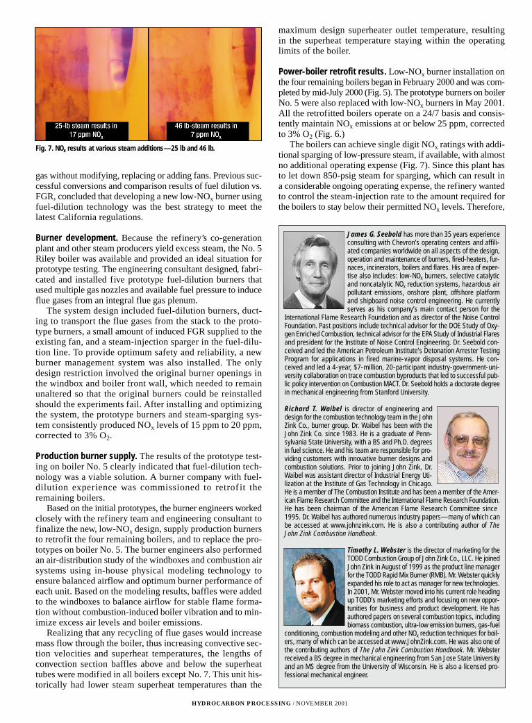
The boilers can achieve single digit NOx ratings with addi-tional sparging of low-pressure steam, if available, with almostno additional operating expense (Fig. 7). Since this plant hasto let down 850-psig steam for sparging, which can result ina considerable ongoing operating expense, the refinery wantedto control the steam-injection rate to the amount required forthe boilers to stay below their permitted NOx levels. Therefore,
HYDROCARBON PROCESSING / NOVEMBER 2001
James G. Seebold has more than 35 years experienceconsulting with Chevron’s operating centers and affili-ated companies worldwide on all aspects of the design,operation and maintenance of burners, fired-heaters, fur-naces, incinerators, boilers and flares. His area of exper-tise also includes: low-NOx burners, selective catalyticand noncatalytic NOx reduction systems, hazardous airpollutant emissions, onshore plant, offshore platformand shipboard noise control engineering. He currentlyserves as his company’s main contact person for the
International Flame Research Foundation and as director of the Noise ControlFoundation. Past positions include technical advisor for the DOE Study of Oxy-gen Enriched Combustion, technical advisor for the EPA Study of Industrial Flaresand president for the Institute of Noise Control Engineering. Dr. Seebold con-ceived and led the American Petroleum Institute’s Detonation Arrester TestingProgram for applications in fired marine-vapor disposal systems. He con-ceived and led a 4-year, $7-million, 20-participant industry-government-uni-versity collaboration on trace combustion byproducts that led to successful pub-lic policy intervention on Combustion MACT. Dr. Seebold holds a doctorate degreein mechanical engineering from Stanford University.
Richard T. Waibel is director of engineering anddesign for the combustion technology team in the JohnZink Co., burner group. Dr. Waibel has been with theJohn Zink Co. since 1983. He is a graduate of Penn-sylvania State University, with a BS and Ph.D. degreesin fuel science. He and his team are responsible for pro-viding customers with innovative burner designs andcombustion solutions. Prior to joining John Zink, Dr.Waibel was assistant director of Industrial Energy Uti-lization at the Institute of Gas Technology in Chicago.He is a member of The Combustion Institute and has been a member of the Amer-ican Flame Research Committee and the International Flame Research Foundation.He has been chairman of the American Flame Research Committee since1995. Dr. Waibel has authored numerous industry papers—many of which canbe accessed at www.johnzink.com. He is also a contributing author of TheJohn Zink Combustion Handbook.
Timothy L. Webster is the director of marketing for theTODD Combustion Group of John Zink Co., LLC. He joinedJohn Zink in August of 1999 as the product line managerfor the TODD Rapid Mix Burner (RMB). Mr. Webster quicklyexpanded his role to act as manager for new technologies.In 2001, Mr. Webster moved into his current role headingup TODD’s marketing efforts and focusing on new oppor-tunities for business and product development. He hasauthored papers on several combustion topics, includingbiomass combustion, ultra-low emission burners, gas-fuel
conditioning, combustion modeling and other NOx reduction techniques for boil-ers, many of which can be accessed at www.JohnZink.com. He was also one ofthe contributing authors of The John Zink Combustion Handbook. Mr. Websterreceived a BS degree in mechanical engineering from San Jose State Universityand an MS degree from the University of Wisconsin. He is also a licensed pro-fessional mechanical engineer.
Fig. 7. NOx results at various steam additions—25 lb and 46 lb.

LK/1M/12-01 Article copyright © 2001 by Gulf Publishing Co.
the team implemented a fuel-gas cascade control scheme toeliminate operator adjustment of steam-injection rates asboiler-firing rates vary.
HYDROGEN REFORMER SOLUTIONLastly, to bring the entire plant into compliance, the team
analyzed the emissions levels and performance of the hydro-gen reformers. Upon reviewing baseline data of the terracewall-fired hydrogen reformer furnace, the team set out toapply a solution similar to the one implemented on the crudeunit. Presently, prototype testing at the burner engineers’ testfurnace has achieved NOx ratings of 10 ppm to 12 ppm.Based on the successful prototype tests, the refinery electedto procure and proceed with manufacture of the productionburners. The team plans to install the production burners inthe first quarter of 2002.
TOTAL PLANT SOLUTION. The result of the cooperative efforts among refinery per-
sonnel, the engineering consultant and burner experts was aninnovative and cost-effective solution to tough emissions
reduction applications. Development efforts met all the pro-ject’s goals, providing more than 90% NOx reduction whilemaintaining safe, reliable combustion performance.
Specifically, the new low-NOx burners for the crude unit per-formed at design conditions while reducing NOx emissions 85%to 95%. This installation used the existing burner tiles andrequired no heater modifications. The “on the run” installationalso required zero crude-unit downtime. Finally, the low-NOxcrude-unit burners eliminated the need for an SCR, saving therefinery $10 million in capital costs and $2 million in annualoperating costs.
Further, successful application of fuel-dilution technologyon all five boilers resulted in more than 90% NOx reduction,allowing all the boilers to meet the targeted limit while expe-riencing substantial cost savings. The boiler-burner retrofit alsoeliminated the need for two SCR systems, saving the refinery$7 million in capital costs and $1.5 million in annual operat-ing costs. Also with additional steam sparging, the burners arecapable of reaching ultra-low-NOx levels of less than 7 ppm.The team expects the projected hydrogen reformer retrofit toachieve a 90% NOx reduction. �
®