Control Function Block Diagrams - Mercer...
21
Control Function Block Diagrams EGR 386 8/26/2011
Transcript of Control Function Block Diagrams - Mercer...

Control
Function Block Diagrams
EGR 386
8/26/2011

Block diagram: terminology

Feedback Basic Terminology• Process: system or central component whose output is to be
controlled
• Actuator: Device that can influence the process and change the process output
• Plant: Combination of Plant and Actuator
• Controller (or compensator): Device that computes the control signal/variable : Combination of Comparator and Compensator
• Senor: Provides an electrical output proportional to variable to be measuredmeasured
• Reference: the desired value for the output of a system, sometimes called Reference Input or Input or Set point
• Output: the process variable of a system to be controlled
• Comparator: Computes the difference between Reference and Output
• Transfer Function: function when multiplied by an Input provides an Output for the component or system being modeled (usually thought of in terms of Laplace transforms for continuous systems)

Temperature Control Function Block
Diagram: Open Loop System
Desired
Input T
Disturbance
Heat flow
in/out QDist
Compensator
TActual
OutputQIn Plant
dV/dt
Actuator
RoomInput
TemperatureFuel
Flow Control
TSET
TActualFurnace
dV/dt
Fuel
Rate

Reference
Input
TempTSET
Error
Disturbance
Heat flow
in/out QDist
TActual
Temperature Control Function Block
Diagram: Closed-Loop Continuous System
OutputQIndV/dt
Compensator Actuator
RoomTSET
TMeasured
+_
ErrorTActual
Temperature
Sensor
Fuel
Flow Control
Furnace
dV/dt
Fuel
Rate

Function block diagram of a room temperature control system, digital output
Room temperature and furnace output vs. time

Plant and Controller• Plant ~= Actuator + Process
• Controller ~= Comparator + Compensator
Disturbance
Plant Controller
Room
Reference
Input
TempTSET
TMeasured
+_
Error
Disturbance
Heat flow
in/out QDist
TActual
Temperature
Sensor
Output
Fuel
Flow Control
QIn
Furnace
dV/dt
Fuel
Rate
Compensator Actuator

Why is feedback needed?
• Disturbances ( weather changes for example)
• Unmodeled plant or actuator characteristics
• Changes plant or actuator

What is required to control a system
Open Loop? • Compensator + Actuator
• Model of system response to control input
What additional is required to control
a system via feedback control? a system via feedback control?
• Output sensor
• Comparator

Modeling of Systems
• Needed to design an appropriate compensator
(whether feedback is used or not)
• Characterize the system performance or best
possible performancepossible performance

Modeling: Dynamic Models

Mechanical Systems: Car Suspension

Electro/Mech. Systems : Disk Drive

Segway

Electronic circuits
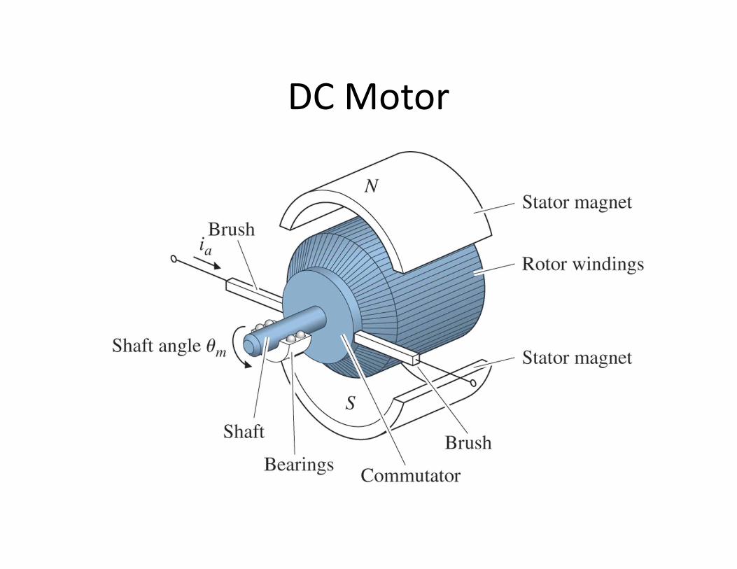
DC Motor

DC motor
• (a) electric circuit of the armature;
• (b) free-body diagram of the rotor

Fluid systems

Thermal Systems (heat transfer)

Steam Engine + Control

Operating parts of a fly-ball governor