![Functional Claiming of Inventions and Related Issues of ......Spring 2017] Functional Claiming of Inventions 359 current law regarding indefiniteness under 112(b), particularly in](https://static.fdocuments.in/doc/165x107/6026f0ac113ab51b6b70d4f5/functional-claiming-of-inventions-and-related-issues-of-spring-2017-functional.jpg)
CONTRIBUTIONS REGARDING STRUCTURAL AND FUNCTIONAL ANALYSIS … · 2018-05-08 · CONTRIBUTIONS...
12
Proceedings in Manufacturing Systems, Volume 6, Issue 3, 2011 ISSN 2067-9238 CONTRIBUTIONS REGARDING STRUCTURAL AND FUNCTIONAL ANALYSIS OF A GANTRY INDUSTRIAL ROBOT NC AXES Adrian NICOLESCU 1,* , Cezara AVRAM 2 1) PhD, Eng., Prof., Department of Machines and Manufacturing Systems, University "Politehnica" of Bucharest 2) Eng., PhD Student, Department of Machines and Manufacturing Systems, University "Politehnica" of Bucharest Abstract: The paper presents the original contributions on structural and functional analysis of numeri- cal controlled (NC) axes of industrial robots (IR) with electric driving system. Main purpose of the paper is to define and validate an assisted selection procedure of IR’s NC axes optimal structure imposed speci- fication accordingly IR’s output for performance level. For this purpose a complex assisted study on NC axes optimum structure of a gantry robot for part handling application and both IR’s NC axes specific performance parameters and their influence on robot’s overall performances has been performed. The method was applied for actual performance evaluation of NC axes structure and electric driving systems performances of a GUDEL gantry IR. The results of study had shown good conformity of procedure and real robot design as well as how real robot design / overall performances may be improved. Key words: industrial robots, numerically controlled axes, optimal design, software modelling, electric driving systems. 1. INTRODUCTION 1 The structural and functional optimization of each IR’s NC axes is essential for increasing the overall per- formance of the IR, as the structure and individual per- formances of each axis, influence IR’s overall perform- ances. This optimization should be done accordingly the application particularities the robot is incorporated in (see Table 1). There is a complete range of the IR overall performance features covering all of the IR constructive types currently operational and respectively, classes of applications they can be incorporated in. In accordance with the particularities of the robotic application, the IR should be evaluated only by those performance criteria that are specific to the robotic applications for which the IR is used, selected from IR’s overall performance cha- racteristics specified in ISO 9283. 2. GENERALIZED ALGORITHM FOR ELECTRIC DRIVEN NC AXIS OPTIMUM COMPONENT’S SELECTION In other words, the type of the robotic application that incorporates the Industrial Robot is one of the most important things to be considered when it comes to de- sign its electro-mechanical structure. To define the opti- mal structure and the sizing of the IR’s NC axis, the fol- lowing elements should be taken into consideration [2, 3]: Load – the magnitude, direction and sense of the re- * Corresponding author: Splaiul Independentei 313, CE 006, sector 6, Bucharest, Romania Tel.: 0744923533; E-mail addresses: [email protected] (A. Nicolescu), [email protected] (C. Avram) sistant forces applied to the driven element of a NC axis; Orientation of the motion axis, the movement plain, po- tential obstacles in the movement plain; Speed, accelera- tion and deceleration along with inertia forces applied to the moving element of the NC axis; Travel – stroke length, actuation elements; Accuracy – in positioning and repeatability in the final index position; Environment – ambient temperature, lubrication con- ditions, the presence of corrosive agents; Duty Cycle – working cycle – motion profile - the ratio of operating and non-operating time and the influence of the static and dynamic behaviour of the IR’s components and as- semblies. Proper consideration for logical approach of all the above mentioned influence factors is presented in the algotithm flow chart illustrated by Fig. 1. Fig. 1. Calculation algotithm flow chart.
Transcript of CONTRIBUTIONS REGARDING STRUCTURAL AND FUNCTIONAL ANALYSIS … · 2018-05-08 · CONTRIBUTIONS...

Proceedings in Manufacturing Systems, Volume 6, Issue 3, 2011
ISSN 2067-9238
CONTRIBUTIONS REGARDING STRUCTURAL AND FUNCTIONAL A NALYSIS OF A GANTRY INDUSTRIAL ROBOT NC AXES
Adrian NICOLESCU 1,*, Cezara AVRAM2
1) PhD, Eng., Prof., Department of Machines and Manufacturing Systems, University "Politehnica" of Bucharest
2) Eng., PhD Student, Department of Machines and Manufacturing Systems, University "Politehnica" of Bucharest
Abstract: The paper presents the original contributions on structural and functional analysis of numeri-cal controlled (NC) axes of industrial robots (IR) with electric driving system. Main purpose of the paper is to define and validate an assisted selection procedure of IR’s NC axes optimal structure imposed speci-fication accordingly IR’s output for performance level. For this purpose a complex assisted study on NC axes optimum structure of a gantry robot for part handling application and both IR’s NC axes specific performance parameters and their influence on robot’s overall performances has been performed. The method was applied for actual performance evaluation of NC axes structure and electric driving systems performances of a GUDEL gantry IR. The results of study had shown good conformity of procedure and real robot design as well as how real robot design / overall performances may be improved. Key words: industrial robots, numerically controlled axes, optimal design, software modelling, electric
driving systems.
1. INTRODUCTION 1
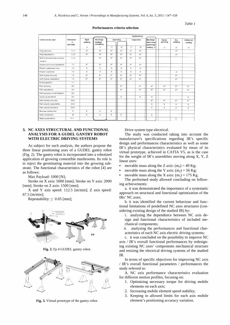
The structural and functional optimization of each IR’s NC axes is essential for increasing the overall per-formance of the IR, as the structure and individual per-formances of each axis, influence IR’s overall perform-ances. This optimization should be done accordingly the application particularities the robot is incorporated in (see Table 1). There is a complete range of the IR overall performance features covering all of the IR constructive types currently operational and respectively, classes of applications they can be incorporated in. In accordance with the particularities of the robotic application, the IR should be evaluated only by those performance criteria that are specific to the robotic applications for which the IR is used, selected from IR’s overall performance cha-racteristics specified in ISO 9283.
2. GENERALIZED ALGORITHM FOR
ELECTRIC DRIVEN NC AXIS OPTIMUM COMPONENT’S SELECTION
In other words, the type of the robotic application that incorporates the Industrial Robot is one of the most important things to be considered when it comes to de-sign its electro-mechanical structure. To define the opti-mal structure and the sizing of the IR’s NC axis, the fol-lowing elements should be taken into consideration [2, 3]: Load – the magnitude, direction and sense of the re-
* Corresponding author: Splaiul Independentei 313, CE 006, sector 6, Bucharest, Romania Tel.: 0744923533; E-mail addresses: [email protected] (A. Nicolescu), [email protected] (C. Avram)
sistant forces applied to the driven element of a NC axis; Orientation of the motion axis, the movement plain, po-tential obstacles in the movement plain; Speed, accelera-tion and deceleration along with inertia forces applied to the moving element of the NC axis; Travel – stroke length, actuation elements; Accuracy – in positioning and repeatability in the final index position;
Environment – ambient temperature, lubrication con-ditions, the presence of corrosive agents; Duty Cycle – working cycle – motion profile - the ratio of operating and non-operating time and the influence of the static and dynamic behaviour of the IR’s components and as-semblies.
Proper consideration for logical approach of all the above mentioned influence factors is presented in the algotithm flow chart illustrated by Fig. 1.
Fig. 1. Calculation algotithm flow chart.
148 A. Nicolescu and C. Avram / Proceedings in Manufacturing Systems, Vol. 6, Iss. 3, 2011 / 147−158
Table 1 Performances criteria selection
3. NC AXES STRUCTURAL AND FUNCTIONAL
ANALYSIS FOR A GUDEL GANTRY ROBOT WITH ELECTRIC DRIVING SYSTEMS
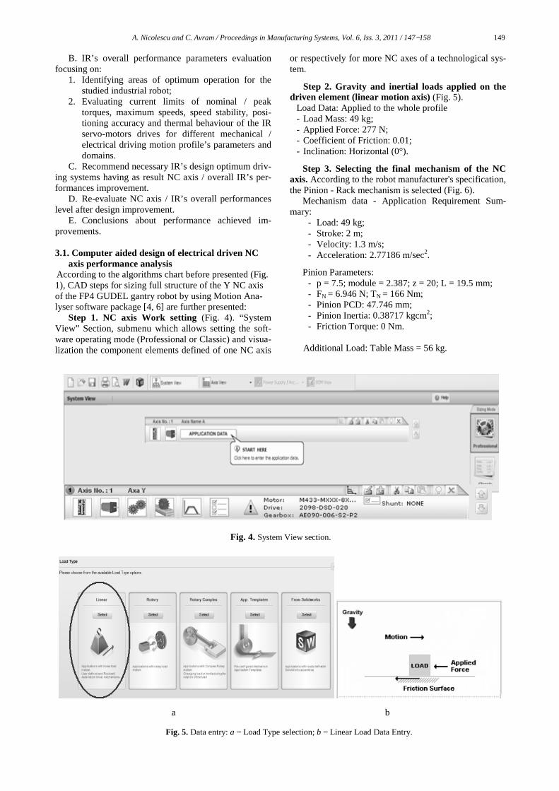
As subject for such analysis, the authors propose the three linear positioning axes of a GUDEL gantry robot (Fig. 2). The gantry robot is incorporated into a robotized application of growing comestible mushrooms. Its role is to inject the germinating material into the growing sub-strate. The functional characteristics of the robot [4] are as follows:
Max Payload: 1000 [N]; Stroke on X axis: 5000 [mm]; Stroke on Y axis: 2000
[mm]; Stroke on Z axis: 1500 [mm]; X and Y axis speed: 112.5 [m/min]; Z axis speed:
67.5 [m/min]; Repeatability: ≤ 0.05 [mm];
Fig. 2. Fp 4 GUDEL gantry robot.
Fig. 3. Virtual prototype of the gantry robot.
Drive system type electrical. The study was conducted taking into account the
manufacturer's specifications regarding IR’s specific design and performances characteristics as well as some IR’s physical characteristics evaluated by mean of its virtual prototype, achieved in CATIA V5, as is the case for the weight of IR’s assemblies moving along X, Y, Z linear axes: • movable mass along the Z axis: (m3) = 49 Kg; • movable mass along the Y axis: (m2) = 56 Kg; • movable mass along the X axis: (m1) = 175 Kg.
The performed study allowed concluding on follow-ing achievements:
a. it was demonstrated the importance of a systematic approach on structural and functional optimization of the IRs’ NC axes;
b. it was identified the current behaviour and func-tional limitations of predefined NC axes structures (con-sidering existing design of the studied IR) by:
i. analysing the dependence between NC axis de-sign and functional characteristics of included me-chanical components; ii. analysing the performances and functional char-acteristics of each NC axis electric driving systems; c. it was concluded on the possibility to improve NC
axis / IR’s overall functional performances by redesign-ing existing NC axes’ components mechanical structure and resizing the electrical driving systems of the studied IR. In terms of specific objectives for improving NC axis / IR’s overall functional parameters / performances the study referred to:
A. NC axis performance characteristics evaluation for different motion profiles, focusing on:
1. Optimizing necessary torque for driving mobile elements on each axis;
2. Increasing mobile element speed stability; 3. Keeping in allowed limits for each axis mobile
element’s positioning accuracy variation.
A. Nicolescu and C. Avram / Proceedings in Manufacturing Systems, Vol. 6, Iss. 3, 2011 / 147−158 149
B. IR’s overall performance parameters evaluation focusing on:
1. Identifying areas of optimum operation for the studied industrial robot;
2. Evaluating current limits of nominal / peak torques, maximum speeds, speed stability, posi-tioning accuracy and thermal behaviour of the IR servo-motors drives for different mechanical / electrical driving motion profile’s parameters and domains.
C. Recommend necessary IR’s design optimum driv-ing systems having as result NC axis / overall IR’s per-formances improvement.
D. Re-evaluate NC axis / IR’s overall performances level after design improvement.
E. Conclusions about performance achieved im-provements.
3.1. Computer aided design of electrical driven NC
axis performance analysis According to the algorithms chart before presented (Fig. 1), CAD steps for sizing full structure of the Y NC axis of the FP4 GUDEL gantry robot by using Motion Ana-lyser software package [4, 6] are further presented:
Step 1. NC axis Work setting (Fig. 4). “System View” Section, submenu which allows setting the soft-ware operating mode (Professional or Classic) and visua-lization the component elements defined of one NC axis
or respectively for more NC axes of a technological sys-tem.
Step 2. Gravity and inertial loads applied on the driven element (linear motion axis) (Fig. 5).
Load Data: Applied to the whole profile - Load Mass: 49 kg; - Applied Force: 277 N; - Coefficient of Friction: 0.01; - Inclination: Horizontal (0°).
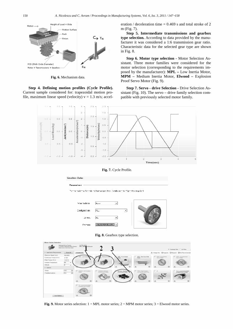
Step 3. Selecting the final mechanism of the NC axis. According to the robot manufacturer's specification, the Pinion - Rack mechanism is selected (Fig. 6). Mechanism data - Application Requirement Sum-mary:
- Load: 49 kg; - Stroke: 2 m; - Velocity: 1.3 m/s; - Acceleration: 2.77186 m/sec2.
Pinion Parameters: - p = 7.5; module = 2.387; z = 20; L = 19.5 mm; - FN = 6.946 N; TN = 166 Nm; - Pinion PCD: 47.746 mm; - Pinion Inertia: 0.38717 kgcm2; - Friction Torque: 0 Nm.
Additional Load: Table Mass = 56 kg.
Fig. 4. System View section.
a b
Fig. 5. Data entry: a − Load Type selection; b − Linear Load Data Entry.
150 A. Nicolescu and C. Avram / Proceedings in Manufacturing Systems, Vol. 6, Iss. 3, 2011 / 147−158
Fig. 6. Mechanism data.
Step 4. Defining motion profiles (Cycle Profile).
Current sample considered for: trapezoidal motion pro-file, maximum linear speed (velocity) v = 1.3 m/s; accel-
eration / deceleration time = 0.469 s and total stroke of 2 m (Fig. 7).
Step 5. Intermediate transmissions and gearbox type selection. According to data provided by the manu-facturer it was considered a 1:6 transmission gear ratio. Characteristic data for the selected gear type are shown in Fig. 8.
Step 6. Motor type selection - Motor Selection As-sistant. Three motor families were considered for the motor selection (corresponding to the requirements im-posed by the manufacturer): MPL – Low Inertia Motor, MPM – Medium Inertia Motor, Elwood – Explosion Proof Servo Motor (Fig. 9).
Step 7. Servo - drive Selection - Drive Selection As-sistant (Fig. 10). The servo – drive family selection com-patible with previously selected motor family.
Fig. 7. Cycle Profile.
Fig. 8. Gearbox type selection.
Fig. 9. Motor series selection: 1 − MPL motor series; 2 − MPM motor series; 3 − Elwood motor series.

A. Nicolescu and C. Avram / Proceedings in Manufacturing Systems, Vol. 6, Iss. 3, 2011 / 147−158 151
Fig. 10. Drive family selection: 1 − ULTRA 3000 series.
• Step 8. “Selection” procedure. Motor family, drive family and gearbox selection in correlation with the NC axis’s structure previously defined (Fig. 11).
• Step 9. Calculus results / all available solutions. Displaying solutions list and
• Step 10. Selection the optimal Electric driving sys-tem solution (Fig. 12) and visualization the component details (for motor, drive and gearbox).
Fig. 11. Sizing and selection (Database options. Full or my Preferred and Search options − Automatic or Manual).
Fig. 13. Details for the optimal selected solutions.
Fig. 12. Selecting the optimal solution.

152 A. Nicolescu and C. Avram / Proceedings in Manufacturing Systems, Vol. 6, Iss. 3, 2011 / 147−158
3.2. Criteria for selection the optimal solution and the analysis of the selected solution performance [5 and 6]
Criteria used for selection the optimal solution were as follows: "Torque −Speed" Diagram (Fig. 14); "Power − Speed" Diagram - the motor and servo - drive use (Fig. 15); the motor thermal regime and servo-drive thermal regime (Fig. 16); the results obtained from the “Simula-tion” − an approximate simulation of the system’s re-sponse during operation in operating conditions - (Fig. 17).
The below figures show diagrams corresponding to these four criteria for a specific database of selected mo-tors accordingly calculated rated and peak torque, as close to manufacturers' recommendations (RMS Torque = 1 Nm, Peak Torque = 5.3 Nm), for velocity v = 1.3 m/s. The specifications for this motor (MPL A220T) are presented in Fig. 13.
Fig. 14. Speed-torque diagram.
Fig. 15. Speed-power diagram.
Fig. 16. Thermal model diagram.
Fig. 17. Results obtained from simulation: 1 − speed stability; 2 − torque stability; 3 − positioning accuracy.
3.3. Assisted analysis of the structure and performance of the studied IR’s NC axes.
When configuring the NC axis of the studied indus-
trial robot (the Y axis) it was taken into account the in-formation provided by the manufacturer in terms of the IR GUDEL FP 4 robot’s mechanical structure, and the electric drive system specifications.
The purpose of was to identify the robot’s overall performance dependence from its NC axis specific beha-vior. [5, 6]. Images corresponding to the four criteria mentioned above are presented next (Fig. 18, Fig. 19, Fig. 20, Fig. 21) for the same version of driving motor. In this case the results are obtained for v = 1.4 m/s. It can be seen very clearly in the thermal diagram that the mo-tor become thermal overloaded at this speed (Fig. 20).

A. Nicolescu and C. Avram / Proceedings in Manufacturing Systems, Vol. 6, Iss. 3, 2011 / 147−158 153
Fig. 18. Speed-torque diagram (position of operation points within the work cycle).
Fig. 19. Speed-power diagram.
Fig. 20. Thermal model diagrams.
Fig. 21. Results obtained from simulation: 1 − speed stability; 2 − torque stability; 3 − positioning accuracy.
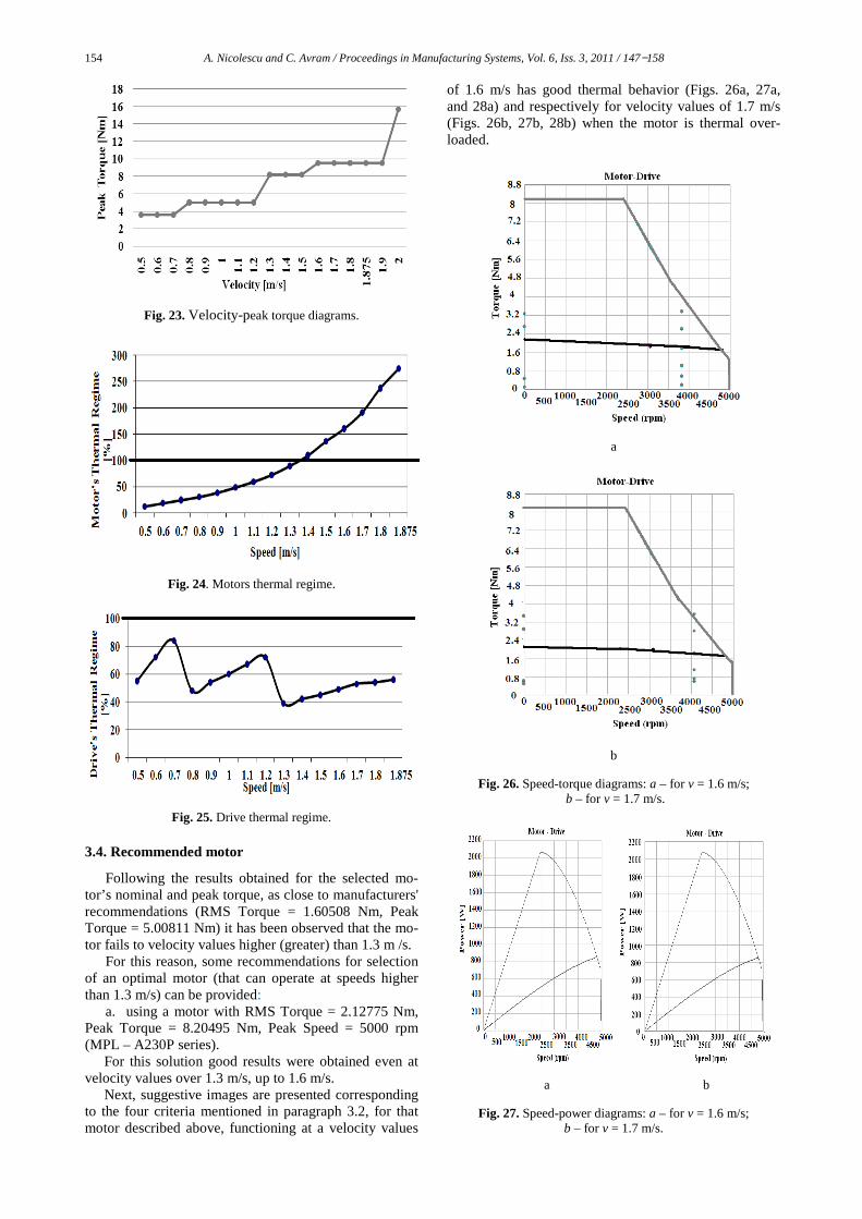
To synthesize the results of the motor functioning
simulation at a velocity from 0.5 m/s to 1.875 m/s, the following two diagrams were represented graphically: “Velocity – Nominal Torque” (Fig. 22) and respectively “Velocity – Peak Torque” (Fig. 24). In Fig 24 is pre-sented the motor’s thermal regime in terms of velocity, and in Fig 25 the drive’s thermal regime in terms of ve-locity. It can be observed that the motor fails to velocity higher than 1.3 m/s.
In terms of nominal torque and peak torque, the listed values are as following: • to achieve travel velocity up to 64% of maximum
velocity, it is necessary to use a driving motor supplying a rated torque of 1.6 Nm and a peak torque of 5.01 Nm;
• to achieve travel velocity rating from 65% and up to 80% of the maximum velocity it is necessary to use a driving motor supplying a rated torque of 2.13 Nm and a peak torque of 8.21 Nm and
• to achieve travel velocity rating from 81% and up to 101% of the maximum velocity it is necessary to use a driving motor supplying a rated torque of 2.94 Nm and a peak torque of 9.51 Nm (Figs. 22 and 23).
Fig. 22. Velocity-nominal torque diagram.
154 A. Nicolescu and C. Avram / Proceedings in Manufacturing Systems, Vol. 6, Iss. 3, 2011 / 147−158
Fig. 23. Velocity-peak torque diagrams.
Fig. 24. Motors thermal regime.
Fig. 25. Drive thermal regime.
3.4. Recommended motor
Following the results obtained for the selected mo-tor’s nominal and peak torque, as close to manufacturers' recommendations (RMS Torque = 1.60508 Nm, Peak Torque = 5.00811 Nm) it has been observed that the mo-tor fails to velocity values higher (greater) than 1.3 m /s.
For this reason, some recommendations for selection of an optimal motor (that can operate at speeds higher than 1.3 m/s) can be provided:
a. using a motor with RMS Torque = 2.12775 Nm, Peak Torque = 8.20495 Nm, Peak Speed = 5000 rpm (MPL – A230P series).
For this solution good results were obtained even at velocity values over 1.3 m/s, up to 1.6 m/s.
Next, suggestive images are presented corresponding to the four criteria mentioned in paragraph 3.2, for that motor described above, functioning at a velocity values
of 1.6 m/s has good thermal behavior (Figs. 26a, 27a, and 28a) and respectively for velocity values of 1.7 m/s (Figs. 26b, 27b, 28b) when the motor is thermal over-loaded.
a
b
Fig. 26. Speed-torque diagrams: a – for v = 1.6 m/s; b – for v = 1.7 m/s.
a b
Fig. 27. Speed-power diagrams: a – for v = 1.6 m/s; b – for v = 1.7 m/s.

A. Nicolescu and C. Avram / Proceedings in Manufacturing Systems, Vol. 6, Iss. 3, 2011 / 147−158 155
b. using a motor with RMS Torque = 2.94807 Nm, Peak Torque = 9.50495 Nm, Peak Speed = 6210 rpm. (M 433 – MXXX – 8X08 series). For this solution good results were obtained even at a velocity values over than 1.5 m/s.
The results obtained from simulation, for velocity values of 1.875 m/s (Fig. 30 a, Fig. 31 a, Fig. 32 a, Fig. 33 a) and respectively for velocity values of 2 m/s (Fig. 30 b, Fig. 31 b, Fig. 32 b, Fig. 33 b) are presented below:
a b
Fig. 28. Thermal model diagrams: a – for v = 1.6 m/s; b – for v = 1.7 m/s.
a b
Fig. 29. Results obtained from simulation: a – for v = 1.6 m/s; b – for v = 1.7 m/s;
where 1 − speed stability; 2 − torque stability; 3 − positioning accuracy.
a b
Fig. 30. Speed-torque diagrams: a – for v = 1.875 m/s; b – for v = 2 m/s.

156 A. Nicolescu and C. Avram / Proceedings in Manufacturing Systems, Vol. 6, Iss. 3, 2011 / 147−158
a b
Fig. 31. Speed-power diagrams: a – for v = 1.875 m/s; b – for v = 2 m/s.
a
b
Fig. 32. Thermal model diagrams: a – for v = 1.875 m/s; b – for v = 2 m/s.
a
b
Fig. 33. Results obtained from simulation: a – for v = 1.875 m/s; b – for v = 2 m/s; 1 − speed stability; 2 − torque stability;
3 − positioning accuracy.
Fig. 34. Motor thermal regime.
Fig. 35. Drive thermal regime.

A. Nicolescu and C. Avram / Proceedings in Manufacturing Systems, Vol. 6, Iss. 3, 2011 / 147−158 157
a
b
Fig. 36. Graphs: a – Velocity-movement stabilization error; b – velocity-positioning precision error.
The motor thermal behaviour dependence by velocity
is presented in Fig. 34, and in Fig. 35 the servo-drive thermal behaviour dependence by velocity. It can be ob-served that the motor fails to a velocity higher than 2 m/s.
Considering the maximum value of IR’s payload, a trapezoidal motion profile and whole range of position-ing speed for each NC axis, the number of operating points at nominal torque diagram (see Fig. 30) and fol-lowing the analysis of the results obtained from the axis performance simulation (see Fig. 33) for the mobile ele-ments positioning error and speed stabilizing, the simula-tion results diagrams for axis output performances are illustrated in Fig. 36.
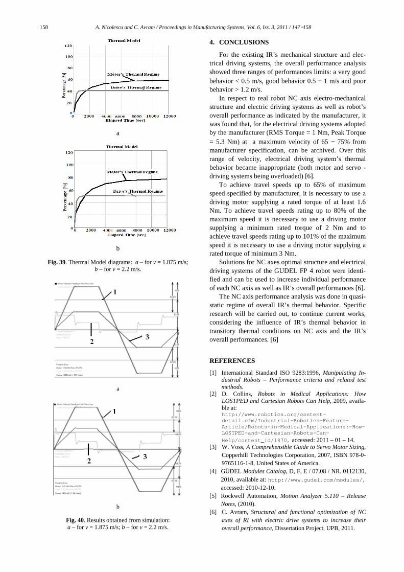
c. using a motor with RMS Torque = 4.72397 Nm, Peak Torque = 15.67855 Nm and Peak Speed = 5200 rpm (M443 –KXXX-8X08 series).
For this solution were obtained good results even at velocity values over than 1.7 m/s. The results obtained from simulation, for velocity values of 1.875 m/s (Fig. 37 a, Fig. 38, Fig. 39 a, Fig. 40 a) and respectively for velocity values of 2.2 m/s (Fig. 37 b, Fig. 38, Fig. 39 b, Fig. 40 b) are presented below.
The differences that occur between these two last al-ternatives proposed for the electrical motor (M 433 – MXXX- 8X08 series and M443 –KXXX-8X08 series), in terms of number of operating points located in nomin-al torque diagram, the thermal regime and the results obtained from simulation for v = 1.875 m/s can be easily seen and compared.
a
b
Fig. 37. Speed-torque diagrams: a – for v = 1.875 m/s; b – for v = 2.2 m/s.
Fig. 38. Speed-power diagrams for v = 1.875 m/s and
v = 2.2 m/s.
158 A. Nicolescu and C. Avram / Proceedings in Manufacturing Systems, Vol. 6, Iss. 3, 2011 / 147−158
a
b
Fig. 39. Thermal Model diagrams: a – for v = 1.875 m/s; b – for v = 2.2 m/s.
a
b
Fig. 40. Results obtained from simulation: a – for v = 1.875 m/s; b – for v = 2.2 m/s.
4. CONCLUSIONS
For the existing IR’s mechanical structure and elec-trical driving systems, the overall performance analysis showed three ranges of performances limits: a very good behavior < 0.5 m/s, good behavior 0.5 − 1 m/s and poor behavior > 1.2 m/s.
In respect to real robot NC axis electro-mechanical structure and electric driving systems as well as robot’s overall performance as indicated by the manufacturer, it was found that, for the electrical driving systems adopted by the manufacturer (RMS Torque = 1 Nm, Peak Torque = 5.3 Nm) at a maximum velocity of 65 − 75% from manufacturer specification, can be archived. Over this range of velocity, electrical driving system’s thermal behavior became inappropriate (both motor and servo - driving systems being overloaded) [6].
To achieve travel speeds up to 65% of maximum speed specified by manufacturer, it is necessary to use a driving motor supplying a rated torque of at least 1.6 Nm. To achieve travel speeds rating up to 80% of the maximum speed it is necessary to use a driving motor supplying a minimum rated torque of 2 Nm and to achieve travel speeds rating up to 101% of the maximum speed it is necessary to use a driving motor supplying a rated torque of minimum 3 Nm.
Solutions for NC axes optimal structure and electrical driving systems of the GUDEL FP 4 robot were identi-fied and can be used to increase individual performance of each NC axis as well as IR’s overall performances [6].
The NC axis performance analysis was done in quasi-static regime of overall IR’s thermal behavior. Specific research will be carried out, to continue current works, considering the influence of IR’s thermal behavior in transitory thermal conditions on NC axis and the IR’s overall performances. [6]
REFERENCES
[1] International Standard ISO 9283:1996, Manipulating In-dustrial Robots – Performance criteria and related test methods.
[2] D. Collins, Robots in Medical Applications: How LOSTPED and Cartesian Robots Can Help, 2009, availa-ble at: http://www.robotics.org/content-detail.cfm/Industrial-Robotics-Feature-Article/Robots-in-Medical-Applications:-How-LOSTPED-and-Cartesian-Robots-Can-
Help/content_id/1870, accessed: 2011 – 01 – 14. [3] W. Voss, A Comprehensible Guide to Servo Motor Sizing,
Copperhill Technologies Corporation, 2007, ISBN 978-0-9765116-1-8, United States of America.
[4] GÜDEL Modules Catalog, D, F, E / 07.08 / NR. 0112130, 2010, available at: http://www.gudel.com/modules/, accessed: 2010-12-10.
[5] Rockwell Automation, Motion Analyzer 5.110 – Release Notes, (2010).
[6] C. Avram, Structural and functional optimization of NC axes of RI with electric drive systems to increase their overall performance, Dissertation Project, UPB, 2011.