THEORETICAL AND EXPERIMANTAL · PDF fileTHEORETICAL AND EXPERIMANTAL CONTRIBUTIONS REGARDING...
18
SISOM 2007 and Homagial Session of the Commission of Acoustics, Bucharest 29-31 May THEORETICAL AND EXPERIMANTAL CONTRIBUTIONS REGARDING ULTRASONIC WELDING PROCESS PARAMETERS OF INTELLIGENT COMPOSITE MATERIALS WITH POLYMERIC MATRIX Amza Gheorghe, Apostolescu Zoia, Ene Tudorel Attaining pieces from intelligent composite materials through welding assemblage, is a highly complex technology because we have to consider a series of elements linked to processing the intelligent composite material and the technological, mechanical and acoustical parameters which have various influences on the welding process. The main elements we have to take into account towards intelligent composite materials processing are: component's characteristics which form the intelligent composite materials; the matrix of the intelligent composite materials; the stiffening elements; sensors or the network of sensors used; geometric shape of joining surfaces; overall dimensions of joining surfaces; properties of each alloying element of intelligent composite materials and the properties of the entire system; way of obtaining the intelligent composite materials; sensors distribution network; required productivity. Main technological parameters of the welding process are: the nature of matrix of the intelligent composite materials; the stiffening element characteristic; the joining surfaces status; the joining materials thicknesses; the conditions requested by the functional role; welding method; the number of acoustic energy concetrators etc. Acoustical parameters are linked to the ultraacoustic system which is also used by the ultrasonic welding gear, and they are: ultrasonic oscillation type which is excited in the system; oscillations amplitude; the intensity of the ultrasonic energy; the density of the ultraacoustic energy; the shape and the material of the sonotrode and the acoustic anvil; the shape factor of the ultrasonic energy concentrator; reflection and absortion qualities of the bearing; the preliminary heating temperature of the sonotrode etc. Mechanical parameters with particular influence on the welding process are: the static contact pressure; the local contact pressure of the joining surfaces; Ultrasonic activation period etc. The synthesis of the welding process parameters are presented in Fig. 1. To optimize the ultrasonic welding process of a intelligent composite material, means to find an objective dependency which includes all the factor showed in Fig. 1, and to determine minimum cost in the process or to determine the maximum productivity in terms of high quality welded joints. In most cases, the study of different parameters influence on the quality of ultrasonic welded joints is made by determining the ultimate strength through shearing and stretching tests at angles of 45° and 90° towards the joining plan. The reproducibility of welded quality is made with the help of variation coheficient k v, given by the following formula: 100 N k m m v ⋅ = σ [%] (1) where: σ m is the deviance at shearing or stretching test; N m – value of the arithmetic mean of the shearing or stretching thrust, which is determined by the equation: ∑ ⋅ = = n 1 i i m N n 1 N (2) where: n represents the individual measurements; N i – the value of individual measurements.
Transcript of THEORETICAL AND EXPERIMANTAL · PDF fileTHEORETICAL AND EXPERIMANTAL CONTRIBUTIONS REGARDING...

SISOM 2007 and Homagial Session of the Commission of Acoustics, Bucharest 29-31 May
THEORETICAL AND EXPERIMANTAL CONTRIBUTIONS REGARDING ULTRASONIC WELDING PROCESS PARAMETERS OF INTELLIGENT
COMPOSITE MATERIALS WITH POLYMERIC MATRIX
Amza Gheorghe, Apostolescu Zoia, Ene Tudorel
Attaining pieces from intelligent composite materials through welding assemblage, is a highly complex technology because we have to consider a series of elements linked to processing the intelligent composite material and the technological, mechanical and acoustical parameters which have various influences on the welding process.
The main elements we have to take into account towards intelligent composite materials processing are: component's characteristics which form the intelligent composite materials; the matrix of the intelligent composite materials; the stiffening elements; sensors or the network of sensors used; geometric shape of joining surfaces; overall dimensions of joining surfaces; properties of each alloying element of intelligent composite materials and the properties of the entire system; way of obtaining the intelligent composite materials; sensors distribution network; required productivity. Main technological parameters of the welding process are: the nature of matrix of the intelligent composite materials; the stiffening element characteristic; the joining surfaces status; the joining materials thicknesses; the conditions requested by the functional role; welding method; the number of acoustic energy concetrators etc. Acoustical parameters are linked to the ultraacoustic system which is also used by the ultrasonic welding gear, and they are: ultrasonic oscillation type which is excited in the system; oscillations amplitude; the intensity of the ultrasonic energy; the density of the ultraacoustic energy; the shape and the material of the sonotrode and the acoustic anvil; the shape factor of the ultrasonic energy concentrator; reflection and absortion qualities of the bearing; the preliminary heating temperature of the sonotrode etc. Mechanical parameters with particular influence on the welding process are: the static contact pressure; the local contact pressure of the joining surfaces; Ultrasonic activation period etc. The synthesis of the welding process parameters are presented in Fig. 1. To optimize the ultrasonic welding process of a intelligent composite material, means to find an objective dependency which includes all the factor showed in Fig. 1, and to determine minimum cost in the process or to determine the maximum productivity in terms of high quality welded joints. In most cases, the study of different parameters influence on the quality of ultrasonic welded joints is made by determining the ultimate strength through shearing and stretching tests at angles of 45° and 90° towards the joining plan. The reproducibility of welded quality is made with the help of variation coheficient kv, given by the following formula:
100N
km
mv ⋅=
σ [%] (1)
where: σm is the deviance at shearing or stretching test; Nm – value of the arithmetic mean of the shearing or stretching thrust, which is determined by the equation:
∑⋅==
n
1iim N
n1N (2)
where: n represents the individual measurements; Ni – the value of individual measurements.

454
The deviance σm is determined with the relationship:
( )1n
NNn
1i
2im
m −
∑ −= =σ (3)
and it's value it's very significant because the error of determination is ± 1.5%
Technological
paramenters
- the nature of components of the intelligent composite
material - the nature of matrix of the intelligent composite material - the nature and shape of the reinforcing elements of the
intelligent composite materials - type of sensors (actuators) - geometric configuration of the joining surfaces - overall dimensions - the thickness of pieces for joining - the properties of each containing element of intelligent
composite materials - the properties of the assembly - sensors' distribution network - Intelligent composite materials obtaining method - welding procedure - required productivity
Ultrasonic welding process parameters of the intelligent
composite materials
Mechanical parameters
- static pressure force - local contact pressure - sonotrode's shape - shape of the acoustic anvil - form factor of the ultrasonic energy concentrator - form factor of the tool - ultrasonic actuating period - friction coefficient - elastic modulus
Acoustical parameters
- acoustic conditions - ultrasounds oscillations amplitude - type of wave excited in the system - acoustic intensity - acoustic energy density - oscillation frequency - reflection and absorption acoustic quality of the bearings
Fig. 1. The parameters for ultrasonic welding process of the intelligent composite materials

455
2. The Influence of the Technological Parameters on the Quality of Ultrasonic Welded Joints
Technological parameters have a direct influence on shape, dimensions and
characteristics of the welded joints, according to the functional role of the piece.
2.1. The Nature of the Materials for Welding
Obtained experimental results showed that weldability (the ability of a material to be welded) of an intelligent composite material depends in the first instance, on elastic modulus, on the toughness of the components and especially on the matrix of the intellient composite material. It was ascertained the bigger the elastic modulus is, the lower the interior losses are, and they allow maximum ultrasonic energy transmission on the welded area with a high efficiency. It was also ascertained that the welding of intelligent composite materials essentially depends on: melting temperature or vitrifying point; resistance to impact; modulus of elasticity; coefficient of friction between the joining surfaces and it's thermal conductiblity. According to Silin, Baladin and Kogan, the criteria for determining the welding behaviour of a material (kr), is the following ratio:
100k sc
0c
r ⋅=σσ
[%] (4)
where: is the yield resistance of the material at room temperature; - yield resistance of the material at the predominant temperature of the joint area.
ocσ s
cσ
The weldabilities are considered to be proper when kr = 0,3...0,25 (weldability decreases inverse proportionally with the ratio).
2.2. Type of sensors (actuators) and sensor distribution network
They don't have a direct influence on the welding parameters nor on the quality of the welded joints. We have to consider though, that the sensor network must be designed in such a manner so it is not interrupted by the welding joint or the sensors are not affected during the welding process, hereby the intelligent composite material proving it's intelligence. We have to consider the position of the sensors' network when designing the piece, so it's functional role is respected and the network is not affected. The undertaken research using fiber optic sensors or piezo ceramic components showed that if these were included in the joint area, it would take place a protection surface deterioration of the optic fiber and a depolarization of the piezo ceramic plates with the loss of sensors' properties.
2.3. Contact profilogram of the joining surfaces
It has a particular influence in practice because every microirregularity of a surface is
an acoustic energy concentrator and the first melting areas will appear in microirregularities 3, of the major heights (Fig. 2). The melted material (4) is expelled in the microdimples of the piece underneath, contributing to melting process acceleration of the other microirregularities, process which is intensified by ultrasonic energy introduced in the joining area.

456
A
P
1
2
43
Fig. 2. Contact profilogram of the joining surfaces: 1; 2 – surfaces for welding; 3 – first microirregularities in contact; 4 – melted material; P - static pressure force;
A – amplitude of the ultrasonic ocillations.
Undertaken research showed the fact that the larger the microirregularities are, the faster the welding process is primed and we can obtain a better quality of the joint.
Joint forming process can be divided convetionally in two stages: - in the first stage, ultrasonic oscillations provoke the heat developing on contact microirregularities between the two surfaces. These microirregularities have a relative movement to each other with an ultrasonic frequency and an amplitude (A), resulting a massive quantity of heat also because of the rubbing contact. Most thermoplastic materials begin melting in a very short time;
- in the second stage, between contact surfaces, heated until plastic state temperature, appear connections which allow the achievement of a resistant joint, after all the microirregularities have melted creating a homogeneous area on the whole contact surface. The temperature in the joining area has to be smaller than the minimum temperature at which, in given conditions, the destroy of the material takes place, and higher than the temperature at which a resistant joint is obtained.
2.4. Welding method
Welding method has an important influence on the joint quality, because related to it, the ultrasonic energy distribution, energy conversant in microirregularities of the surfaces, ultrasonic energy dosage and the degree of continuity and mechanization of the welding process, they all take place.
Based on the ultrasonic energy dosage and repartisation in the joining surfaces, two welding methods are used: - "close field" welding or contact ultrasonic welding, when the sonotrode is as close as possible to the joining area. (Fig. 3, a). In this case, the ultrasoni energy is evenly distributed on the whole contact surface of the pieces for welding (1 and 2). The front part of the sonotrode (3), which is in contact to the superior piece, has identical shape and surface to that of the pieces for welding. This method is used when welding the mellow plastic materials such as: polyethylene, plastifyied PVC and others with 6 mm thicknesses or less, achieving lap joints.

457
A
P
=6,
0mm
4
1
23
5
P
A4
1
52
3
> 6
mm
a b
Fig. 3. Ultrasonic welding methods of the intelligent composites:
a - „close field”; b -,,far field”: 1 – superior piece; 2 – inferior piece; 3 - acoustic anvil; 4- sonotrode; 5 – joining area.
- „far field” welding, when the ultrasonic oscillations are applied in a certain point or
on a small area of the superior piece (Fig. 3, b) and the welding takes places in a far off area of the sonotrode. Evenly distribution and transmission of the ultrasonic energy depends, in this case, on the plastic materials ability to transmit the mechanical vibrations, that is why "far-field" welding is recomended for hard plastic materials such as: polystyrene, polymethacrylate, polycarbonate, ABS, etc. The most common joint are butt-joints and lap-joints
3. Acoustical parameters influence on the ultrasonic welding quality of the intelligent composite materials
One of the factors determining the joint quality is the appearance and developing plastic deformation in the layers of materials for welding, on which the acoustic conditions have a particular influence. Different acoustic conditions can be produced by different types of oscillations on joining elements: longitudinal, shearing, bending, twisting and combinations of these, whose excitation in the joining area is made by projecting, constructing and execution specific for ultraacoustic systems used for creating and propagation of the ultrasonic oscillations. Conducted experimental research showed that by excitation of longitudinal waves in the sonotrode (meaning the calculation of the ultraacoustic system and of the resonant frequency of the longitudinal waves), the weld resistance and the coefficient of variation kv depend on the sonotrode's length and on the place where the static pressure force is applied. The quality of welded joints obtained with systems in which flexual vibrations are created and conveyed, is lower than the quality of those produced by longitudinal waves; this is explained by high variation of system input resistance when the frequency is self-regulated. Experimental results for some composite materials with polymeric matrix showed that the most efficient ultraacoustic systems are those in which flexual vibrations or longitudinal and transversal oscillations are excited and conveyed because they insure the best removal and distruction of the oxide layers off the joining surfaces, they manage to better restrict the oxygene inclusion in the contact zone, they produce a complex movement of the material in the contact zone, and they create favorable conditions for achieving the best quality joints.

458
3.1. Influence of the ultrasonic oscillations amplitude on the quality of the welded joints The process of welded joint formation with the help of ultrasonic oscillations mostly depends on sonotrode's oscillations amplitude As and of static pressure force Ps . Oscillations from sonotrode 1 are transmitted to the welding material 2 and 3 (Fig. 4) and to the acoustic anvil 4, each vibrating with corresponding amplitudes, with the condition:
As > Aps > Api > An (5)
P
A 1
2
3
4
A
AA
A
l
s
pspi
n S
S
s
0.2
0.4
? E
Materialul = ABS
Frecventa = 20kHz
0.4 0.8
µ0.1
0.3
0.5
0.6
0.2 0.6 1.0
Fig. 4. Vibration design when welding with ultrasounds the composite materials with polymeric
matrix: 1- sonotrode; 2 - superior piece; 3 –inferior piece;
4-acoustic anvil.
Fig. 5.Energy loss ΔE, term of dry friction coefficient μ, at a frequency of 20kHz.
Δ E
Between the sonotrode and the superior piece 2 acts an Fs force, given by the formula: Fs = As sin ωt (6) and between pieces 2 and 3, acts a friction force Ff, described by the equation: Ff = As sin ωt (7) and static pressure force Ps. Relationship between these two forces is: Ff ≤ μPs (8) As long as Ff ≤ μPs, the two materials oscillate without intercrescence, the intercrescence appearing when Ff >Ps and when the energy loss ΔE is highest (Fig. 5). An optimum value for static pressure force (Ps opt) was determined experimentally: Ps opt = Sc·σc° (9) where: Sc is the contact surface between the sonotrode and the superior piece; σc°- yield limit of the material at a temperature of 20°C. Knowing the optimum value of the pressure force we can determine the optimum amplitude of the sonotrode regarding the optimal peripheral force Pt opt is: Pt opt = k · μ · Psopt (10) and leads to displacing tensions appearance in the weld zone τf:

459
τf = τx · sin ωt (11)
The connection between τx, Aps and Api is:
khG
10AA xpips +=−
τ (12)
where: h is the height of the plastic deformation zone; G – the shearing modulus; τx – yield limit share in the weld zone and is defined by:
2
s2s
sx a3mP
1 ⎟⎟⎠
⎞⎜⎜⎝
⎛−⋅=
τπττ (13)
where: m is a coefficient depending on the sonotrode's construction (m = 0, 1, 2, 3,); τs- yield limit share of the sonotrode construction material; a – coefficient depending on the thicknesses of the pieces (a = 1...3s); s – thicknesses of the pieces. For example, for intelligent composite materials with polymeric matrix (ABS) the following relationship was found, illustrating an optimum tie:
Aps = 0,7 As; Api = 0,4 As; ⎟⎠⎞
⎜⎝⎛ += kh
G103,3A x
sτ
(14)
Fig. 6 shows the amplitude's influence on the tensile strength of the weld. It can be noticed that if ultrasonic vibration amplitude is reduced, the weld resistance would also be reduced Fr , and at values less than a minimum stated value As min the joint doesn't take place anymore. Acoustic energy dosage in the weld zone also depends on the oscillations amplitude of the sonotrode's front side, acoustic energy which has to be higher in the first stage of the intimate contact between the surfaces. After the physic contact was created, during the focal spot interaction forming stage between the joining surfaces followed by their contact increase, it is necessary that the oscillation amplitude is reduced to 50% of it's initial value for preventing the breaking of the existent connections. In this stage, the whole acoustic energy is spent to hurry the plastifying and melting processes of the material from the joining area.
20
30
Fr[daN]
15 25
As [µm]15
25
35
40
10 20 30
45
105 35
t = 1.0 s
t = 0.5 s
t = 0.15 s
t = 2.0 s
t [s]
As Materialul = ABSFrecventa = 20kHz
5
42
3
1
35
35
35
35
2.01.51.00.5
Fig. 6. Influence of the sonotrode's amplitude As on the tensile strength Fr, at different welding times.
Fig. 7. Sonotrode's amplitude variation As with time, for different types of oscillations:
1- longitudinal; 2 – at shearing; 3- at bending; 4- longitudinal-torsional; 5 – torsional
As [μmm]
The temperature increase in the contact zone increases the thermal energy of atoms, which is in favor of transfer process of the material into the existent pits, which will affect the diffusion

460
process. Consequently, the amplitude's variation in the two stages of the weld forming process must be as in Fig. 7, depending on the type of oscillation excited and propagated in the sonotrode.
Sonotrode's amplitude variation with the transducer's output power Wt is presented in Fig. 8, where it is ascertained that as the output power increases, the sonotrode's oscillations amplitude increases in all cases.
10
20
Materialul = ABS
Frecventa = 20kHz
70 110 Wt [W]
5
15
25
50 90
As [µm]5
4
2
3
1
3
7
Materialul = ABSFrecventa = 20kHz
10 20
1
5
9
5 15
Fr [daN]
5
3
4
2
1
As [µm]3025
9
Fig. 8. Sonotrode's amplitude variation with the transducer's output power Wt for different types of
oscillations: 1- longitudinal; 2 – shearing; 3- bending; 4-
longitudinal-torsional; 5 – torsional.
Fig. 9. Tensile strength variation Fr, with ultrasonic oscillation amplitude of the sonotrode As, for different
types of oscillations: 1- longitudinal; 2 – shearing; 3- bending; 4-
longitudinal and torsional; 5 – torsional. It is experimentally ascertained that the mechanical resistance Fr of the ultrasonic welded joints has an optimum value for a certain amplitude and for a certain type of excitation in the ultraacoustic system. (Fig. 9). Contact surface Sk, among the contact microirregularities, increases with the increase of the transducer's output power Wt (Fig. 10), easily explainable phenomenon because of the substantially increase of thermal energy by overlying the acoustic energy to it. Almost the same we have the increase of intercrescence depth hp of the microirregularities, which finally form the weld zone. (Fig. 11)
4
8
Materialul = ABS
Frecventa = 20kHz
70 110 Wt [W]
2
6
10
50 90
Sk [10 mm ]
5
4
2
3
1
-2 2
12
0.4
0.8
Materialul = ABS
Frecventa = 20kHz
70 110 Wt [W]
0.2
0.6
1.0
50 90
hp [mm]
5
4
23
11.2
1.4
Fig. 10. Contact surface variation Sk, with transducer's output power Wt, for different types of oscillations:
longitudinal; 2 – for shearing; 3 - for bending; 4 - longitudinal and torsional; 5 – torsional.
Fig. 11. Intercrescence depth variation with hp,transducer's output power Wt,
for different types of oscillation : 1 - longitudinal; 2 – shearing; 3- banding; 4 - longitudinal and torsional; 5 – torsional.

461
3.2. Influence of the ultrasonic oscillations frequency on the welded joint quality
The problem of optimum frequency detemination when welding with ultrasounds the intelligent composite materials is made regarding the oscillation amplitude, ultrasonic waves intensity, contact pressure, nature of composite materials and their thickness.
Experiments showed that the higher ultrasounds frequency, the lower oscillations amplitude at a certain transducer's output power, which leadsa to the conclusion that there is a certain frequency whereon we can obtain a good quality of the weld
Obtained experimental results showes that there is an optimum frequency (Fig. 12) related to material's nature and transducer's output power, in the range 19-40kHz.
20
30
Fr[daN]
15 25
?[kHz]
15
25
10 20 30
10
35 40 45
5
5
4
3 1
2
20
30
Fr[daN]
4 8
Iu[w/cm ]
15
25
2 6 15
10
52
3
1
2
As = 23µmPs = 10 daNDf = 30 mm
ν [kHz]
Fig. 12.Tensile strehgth variation Fr of welded joints, related to frequency ν, of ultrasounds, for different plastic materials:
1- ABS; 2 – polystirene; 3 – polycarbonate; 4 – hard polymerized vinyl chlorhide; 5 – high density polyethylene
Fig. 13. Tensile strehgth variation Fr of welded joints, with acoustic energy density Is,
for different plastic materials: 1- ABS; 2 – high density polyethylene; 3 –
polycharbonate.
3.3. Influence of the acoustic intensity on welded joints
Determination of an optimal acoustic density is a highly complex procedure because it depends not only on the ultraacoustic output power and the amplitude from sonotrode's tip, but of oscillation type which is propagated in the ultraacoustic system, the shape of welded joint, the size of the contat surfaces and the nature of the materials to join. Experimentally is ascertained that as the acoustic energy density increases, the time until joint formation decreases and the joint's tensile strength increases (Fig. 13) existing an optimum value, explainable phenomenon because if a certain value of acoustic density is exceeded, the thermal energy from the contact zone increases and the material begins to collapse. The acoustic energy density influention over can be very different, depending on the material's nature and it's overall dimensions. There is always an optimum value of the acoustic energy density, depending on the nature of the material, the amplitude and the static contact pressure of the sonotrode in the welding area.

462
4. Influence of the mechanical parameters on the quality of the ultrasonic welds of the intelligent composite materials
Mechanical parameters are the result of the flow sheet used to design and construct the welding equipment. Generally, the equipment built for ultrasonic welding allows more welding schedules, depending on the shape and dimensions of the ultraacoustic system which can be fixed or detachable. Main mechanical parameters, with high influence on the weld quality are: static contact pressure, local contact pressure, ultrasonic activation period, sonotrode's shape, acoustic anvil shape, form factor of sonotrode and concentrator et. al.
4.1. Influence of the static pressure force on the quality of the ultrasonic welds of the intelligent composite materials
Theoretical and experimetal research revealed that the static pressure force decisively influence the mean tensile strength of the ultrasonic welds. As seen in Fig. 14, when welding the intelligent composite materials with ABS matrix, an optimum value for the static pressure force is determined, optimum value which depends on the activation time ts and the sonotrode's amplitude As (Fig. 15).
20
30
Fr[daN]
1.0 2.0
t [s]
15
25
0.5 1.5
10
5
4
3
1
Materialul = ABSAmplitudinea As = 25µmFrecventa : ?
2
= 20 kHz
20
30
10 20
Ps [daN]
15
25
5 15 25
10
5
3
As [µm]
4
1
2
35
Materialul = ABSAmplitudinea As = 30µmFrecventa : ? = 20 kHz
ν = 20kHz
ts
Fig. 14. Influence of the static pressure force and ultrasonic activation period on the weld resistance,
with the following conditions: 1- PS = 5daN; 2- PS = 10daN; 3 - PS = 15daN; 4 - PS
= 20daN.
Fig. 15. Influence of the static pressure force Ps on the amplitude value As, at different values of the acoustic
energy density: 1- 2 W/cm2; 2 - 4 W/cm2; 3 – 6 W/cm2; 4 – 8 W/cm2.
As seen in Fig. 15 there is a tight connection between the static pressure force and the
amplitude of the active part of the ensemble As, which means, as static pressure force increases, the amplitude of the active part of the sonotrode decreases, and when exceeding the optimum value of the static pressure force the weld resistance substantially decreases.
Static pressure force has a particular influence on the local static contact pressure (Fig. 16) increasing togheter with the static pressure force, at different acoustic energy densities.

463
Static pressure force in chosen term of the pieces thicknesses, existing an optimum value for the weld resistance Fr (Fig. 17) term of thickness and static pressure force.
8
12
10 20
Ps [daN]
6
10
5 15 25
4
2
3
4
1
2
Materialul = ABSAmplitudinea As = 25µmFrecventa : ? = 20 kHz
Pc [daN/cm ]2
20
30
10 20Ps [daN]
15
25
5 15 25
10
5
3
1
2
35
Materialul = ABSAmplitudinea As = 25µm
? = 20 kHzFrecventa :
Fr[daN]
Fig. 16. Influence of the static pressure force Ps, on the local contact pressure Pc, at different acoustic energy
densities: 1- 2 W/cm2; 2 - 4 W/cm2; 3 – 6 W/cm2; 4 – 8 W/cm2.
Fig. 17. Influence of the static pressure force Ps, on the weld resistance Fr, at different thicknesses:
1- s = 1,0+1,0; 2 - s = 2,0+2,0; 3 – s = 3,0+3,0.
4.2. Influence of the local contact pressure on the quality of ultrasonic welds of intelligent composite materials
Experimaental results on different materials revealed that the local contact pressure varies and depends not only on the static pressure force but also on the thicknesses of the pieces and on the dimensions and geometric configuration of the welding area. It can be ascertained, as we pass from stage one to stage two of the welding process, the contact zone increases and local contact pressure decreases (Fig. 18) and consequently the weld resistance decreases, existing a limit above which the joining doesn't take place.
8
12
1.0 2.0
t [s]
6
10
0.5 1.5 2.5
4
2
Pc [daN/cm ]2
1
3
2
Fig. 18. Influence of ultrasonic welding process duration ts
on local contact pressure pc for different plastics: 1- ABS; 2 – high density polyethylene; 3 – polycarbonate.
The local contact pressure is depending on the configuration of the contact zone, and, in order to make the joining possible, the contact zone has a certain shape in the first stage of the process corresponding to pieces thicknesses, the geometric configuration of the joining area and the piece functional role (Fig. 19). It is ascertained that the machined acoustic energy concentrators from the contact zone attain not only a quickly focus of thermal energy in the local area of joining but also a much higher static contact pressure in these areas, a pressure which decreases as the concentrators melt or plastic deform, increasing the contact zone.
ν = 20kHz ν = 20kHz
ts
The number, size and distances whereat the acoustic and thermal energy concentrators are placed depend on geometric configuration of the weld and on the types of materials used. Preparation mode presented in Fig. 19, d is particulary determined for making the intelligent stop light or for making the intelligent motor bar, with the role of optic and acoustic signalling the approach of the vehicle at a risking distance.

464
ss
s/10
s/5
1
3
2
ab
s/5
s/10
s
s/3
s/3
1
3
2
s/5s/5
s/10
s/12s
s/21
3
2
c
1 4
32
s/5
s
s/12
s/10
s/20
d Fig. 19. Preparation mode for the contact zone depending on the pieces thicknesses and the needed local contact
pressure: a – with gap; b – stepped; c – grooved wedge; d – special; 1 - superior piece; 2 –inferior piece; 3 – acoustic
energy concentrator; 4 – piezoceramic plates.
4.3. Influence of welding time on the quality of the ultrasonic joints of intelligent
composite materials
Welding time, meaning the time of ultrasonic waves acting on the contact zone, has a particular influence not only on the possibility of making the joints but also on quality of welds and on welds resistance.
20
Fr[daN]
1.0 2.0
t [s]
15
25
0.5 1.5
10
5
4
3
1
Materialul = ABSAmplitudinea As = 25µmFrecventa :
2
? = 20 kHz
20
30
Fr[daN]
1.0 2.0
t [s]
15
25
0.5 1.5
10
5
3
Amplitudinea As = 25µmFrecventa : 0 kHz
2
? = 2
1
ts
ts
ν = 20kHz ν = 20kHz
2.5
Fig. 20. Influence of welding time ts, on weld resistance Fr, depending on pieces to join:
1- 1,0+1,0; 2 - 2,0+2,0; 3 – 3,0+3,0; 4 – 4,0+4,0.
Fig. 21. Welding time influence ts, on weld resistance Fr, depending on materials to weld: 1– high density polyethylene; 2- ABS; 3 –
polycarbonate.

465
The obtained experimental results showed that there is an optimum value of welding time depending on the thicknesses of the pieces (Fig. 20), the maximum weld resistance moving according to the decrease of thicknesses. For setting the right welding time we have to take into acoount the materials of the pieces to join, activation period being very different term of the joining materials properties(Fig. 21).
Ultrasounds acting time in the contact zone depends not only on the nature of the materials for welding but also on the thicknesses of pieces to weld, on the static pressure force (Fig. 22) and on the shape of the sonotrode's section in the contact area. (Fig. 23).
20
30
Fr[daN]
1.0 2.0
t [s]
15
25
0.5 1.5
10
5
3
2
1
2.5
20
30
Fr[daN]
1.0 2.0
t [s]
15
25
0.5 1.5
10
5
3
1
2
2.5
ts ts
Fig. 22. Influence of welding time ts, on weld resistance Fr, depending on the static pressure force:
1- PS = 15daN; 2- PS = 25daN; 3 - PS = 35daN.
Fig. 23. Influence of welding time ts, on weld resistance Fr, depending on the sonotrode's final
section: 1- round section, 2 – square section; 3 – other section.
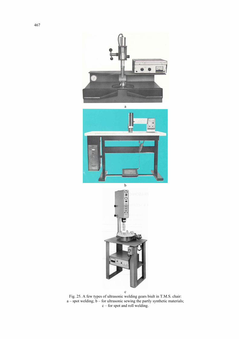
The plastic yield speed is in direct correlation with welding time, because the increase of plastic yield for a short period of time, on basis of acoustic energy application in the welding zone, creates favorable terms for initiating the joining process. Experiments were conducted on equipments from different companies (Fig. 24) or on instalations built in TMS chair as propotypes (Fig. 25), on different composite materials (Fig. 26) or on different products (Fig. 27). Observation! Besides mentioned and above discussed parameters, the quality of welds made with ultrasounds in case of intelligent composite materials, also depends on other parameters such as: the sonotrode's material, contact surface status and quality between the sonotrode and the piece, cleaning state of the joining area, the material of the acoustic anvil, state and quality of the inferior acoustic anvil, physical status of the contact zone of the two joining materials; environmental conditions in which the welding process takes place etc.
5. Conclusions 1° The making of pieces from intelligent composite materials through ultrasonic welding assemblage is a highly complex technology because we have to regard a series of elements related to the intelligent composites processing and also on the technological, mechanical and acoustical parameters which have a different influence on the welding process.

466
a b
c d Fig. 24. Types of ultrasonic welding equipments used for welding the plastic and compound materials:
a; b –BRANSON; c –CAVITRON; d –DUKANE.
467
a
b
c
Fig. 25. A few types of ultrasonic welding gears biult in T.M.S. chair: a – spot welding; b – for ultrasonic sewing the partly synthetic materials;
c – for spot and roll welding.

468
a
b
c
d
e
f
Fig. 26. Different compound materials user for experiments: a; f – intelligent composite materials with thermorigid polymeric matrix; b - intelligent composite materials with thermoplastic polymeric matrix; c - hard P.V.C. elements; d; e – intelligent stop light; f with different types of
matrices and different reinforceing elements.

469
a
b
Fig. 27. A few products obtained through ultrasonic welding: a – different plastics; b – intelligent composite materials with polymeric matrix.
470
2° Main technological parameters which should be optimized in the ultrasonic welding process of intelligent composite materials are: the components' nature of the intelligent composite materials, the matrix nature; reinforceing elements nature and shape, type of sensors (actuators), surfaces geometric configuration; overall dimensions of the contact zones; the pieces thicknesses; physical, chemical and mechanical properties of each containing element of intelligent composite materials; the properties of the whole assemblage; sensor distribution network (actuators), the methods for obtaining the intelligent composite materials; welding method; required productivity etc. 3° Main mechanical parameters of the ultrasonic welding process, when welding the intelligent composite materials are: static pressure force, static contact pressure, sonotrode's shape, shape of the acoustic anvil, ultrasounds activation time; coefficient of friction; elasticity modulus, hardness etc. 4° Main acoustical parameters of the process are: acoustic conditions; ultrasonic oscillations amplitude; ultrasonic oscillations frequency; type of wave excited in the ultraacoustic system; acoustic energy density; reflection and absorption quality of bearings etc. 5° The quality of welded joints with ultrasounds of an intelligent composite material also hinges on other parameters which were not discussed in this chapter: sonotrode's building materials; status and quality of the contact surface between the sonotrode and the piece; cleaning status of the welding area; the nature of the acoustic anvil material; state and quality of the acoustic anvil's surface; physical status of the limit contact zone of the two joining materials; environmental conditions in which the welding takes place and others. 6° To optimize the ultrasonic welding process of a intelligent composite material, means to find an objective dependency which includes all the factor showed in Fig. 1, and to determine minimum cost in the process or to determine the maximum productivity in terms of high quality welded joints.