ContiTech Oil & Marine High Performance Flexible Hoses Oil & Marine manufactures an extensive range...
37
ContiTech Oil & Marine High Performance Flexible Hoses
-
Upload
dangkhuong -
Category
Documents
-
view
248 -
download
8
Transcript of ContiTech Oil & Marine High Performance Flexible Hoses Oil & Marine manufactures an extensive range...
ContiTech Oil & Marine High Performance Flexible Hoses

2 3
IntroductionHigh Performance Flexible Hoses
ContiTech Oil & Marine, part of Continental AG, is a global leader in the design, manufacture and supply of flexible hoses. With products in operation at installations throughout the world, we pride ourselves on being experts in specialist hoses and fluid transfer systems for the oil and gas explo-ration and production industries.
We aim to provide you with a total solution for your flexible hose requirements, and can assist with all elements of your project – from the feasibility stage, through to design, engineering and manufacture, as well as project management, installation, training and after-care too. So whatever your project requirements, we will provide you with a completely bespoke service.
Contents
Hose & Couplings 4Summary 5 Fuel and Oil 6Dock Loading 8Chemical Suction 9Concrete Pumping Liquid Mud 10Bulk Material 11Salamander 13
Bulk Material Fuel and Oil Liquid Mud 14Potable Water
Compressed Air 15Potable Water 16Saturated Steam 17Nitrogen Multipurpose 18Water Thermoplastic 20
Hydraulic 21Single Wire Braid 21Double Wire Braid Four Spiral Wire Hydraulic 22Four or Six Spiral Wire Hydraulic 23Hydraulic Slim Line Rotary Hydraulic 24
Fireshield 24Fuel & Oil Suction & Delivery 24Blow out Preventor Control 25Fire Resistant Firewater Deluge
Couplings 26Summary 27Hose Couplings 28
High Pressure Hoses 40Summary 41Mud and Cement Hoses 42Rotary & Vibrator
with built-in couplings 43with swaged couplings 44
Cementing 45Underbalanced Drilling 46Choke & Kill
Selection Guide 47smooth bore 48rough bore 49
Production Extreme gas & liquid service 50Rough Bore gas & liquid service 51
Flexible Lines 52Customised Solutions 53Well-test 54Flexible Riser Tensioner Lines 55Preformed Bonded Flexible Hoses 56
High Pressure Couplings 58Basic Coupling Selection 58
Technical 60Hose Management 61Hose Handling 62Solvent Information 65Chemical Resistance 66Conversion Charts 68Quality 70
Hose & CouplingsLow Pressure Hoses
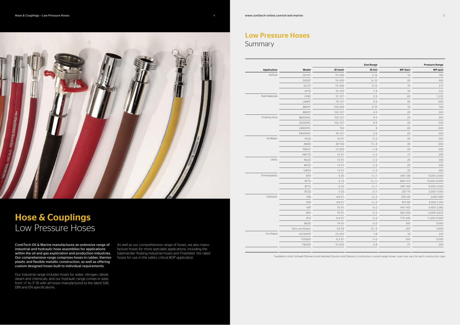
ContiTech Oil & Marine manufactures an extensive range of industrial and hydraulic hose assemblies for applications within the oil and gas exploration and production industries. Our comprehensive range comprises hoses in rubber, thermoplastic and flexible metallic construction, as well as offering custom designed hoses built to individual requirements.
Our industrial range includes hoses for water, nitrogen, diesel, steam and chemicals, and our hydraulic range comes in sizes from 1⁄8" to 3" ID with all hoses manufactured to the latest SAE, DIN and EN specifications.
As well as our comprehensive range of hoses, we also manu-facture hoses for more specialist applications, including the Salamander floating industrial hoses and Fireshield fire rated hoses for use in the safety critical BOP application.
54 www.contitechonline.com/oilandmarineHose & Couplings – Low Pressure Hoses
Low Pressure HosesSummary
Application Model
Size Range Pressure Range
ID (mm) ID (in) WP (bar) WP (psi)
Oil/Fuel DO10* 51–305 2–12 10 150
DO20* 10–305 3⁄8–12 20 300
DL15* 75–300 3–12 15 217
UP16 25–102 1–4 16 232
Bulk Materials CP85 51–127 2–5 85 1,232
LM40* 76–127 3–5 40 600
BM10* 102–254 4–10 10 150
BM20* 102–127 4–5 20 300
Floating Hose BM20HFL 102–127 4–5 20 300
DO20HFL 102–127 4–5 20 300
LM40HFL 102 4 40 600
PW20HFL 76–127 3–5 20 300
Air/Water AT20 10–51 3⁄8–2 20 300
AW40 38–102 11⁄2–4 40 600
PW20* 13–203 1⁄2–8 20 300
HW17S 13–51 1⁄2–2 17 255
Utility NG20 13–51 1⁄2–2 20 300
MP20 13–51 1⁄2–2 20 300
UW20 13–51 1⁄2–2 20 300
Thermoplastic BT9 5–25 3⁄16–1 345–138 5,000–2,000
BT10 5–13 3⁄16–1⁄2 689–414 10,000–6,000
BT13 5–25 3⁄16–1 345–140 5,000–2,000
BT20 3–25 1⁄8–1 207–70 3,000–1,000
Hydraulic 1SN 4.8–51 3⁄16–2 250–40 3,600–580
2SN 4.8–51 3⁄16–2 415–80 6,000–1,150
4SP 10–51 3⁄8–2 445–165 6,450–2,360
4SH 19–51 3⁄4–2 420–250 6,090–3,625
R13 6.4–51 1⁄4–2 776–345 11,250–5,000
BX20 19–51 3⁄4–2 345 5,000
Slim Line Rotary 63–76 21⁄2–3 207 3,000
Fire Rated DO16HFR 25–203 1–8 16 232
FS5000 6.3–51 1⁄4–2 350 5,000
FW300 51–203 2–8 21 300
*available in both Softwall (Delivery) and Hardwall (Suction and Delivery) construction; overall range shown, sizes may vary for each construction type
6 7www.contitechonline.com/oilandmarineHose & Couplings – Low Pressure Hoses
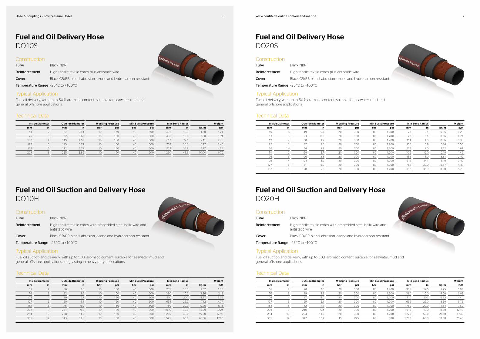
Fuel and Oil Delivery HoseDO10S
ConstructionTube Black NBR
Reinforcement High tensile textile cords plus antistatic wire
Cover Black CR/BR blend; abrasion, ozone and hydrocarbon resistant
Temperature Range –25 °C to +100 °C
Typical ApplicationFuel oil delivery, with up to 50 % aromatic content, suitable for seawater, mud and general offshore applications
Technical Data
Inside Diameter Outside Diameter Working Pressure Min Burst Pressure Min Bend Radius Weight
mm in mm in bar psi bar psi mm in kg/m lb/ft
51 2 67 2.64 10 150 40 600 306 12.0 1.80 1.21
76 3 92 3.62 10 150 40 600 456 18.0 2.60 1.74
102 4 119 4.69 10 150 40 600 612 24.1 4.11 2.75
127 5 145 5.71 10 150 40 600 762 30.0 5.17 3.46
152 6 172 6.77 10 150 40 600 912 35.9 6.77 4.54
203 8 225 8.86 10 150 40 600 1,260 49.6 10.00 6.70
Fuel and Oil Delivery HoseDO20S
ConstructionTube Black NBR
Reinforcement High tensile textile cords plus antistatic wire
Cover Black CR/BR blend; abrasion, ozone and hydrocarbon resistant
Temperature Range –25 °C to +100 °C
Typical ApplicationFuel oil delivery, with up to 50 % aromatic content, suitable for seawater, mud and general offshore applications
Technical Data
Inside Diameter Outside Diameter Working Pressure Min Burst Pressure Min Bend Radius Weight
mm in mm in bar psi bar psi mm in kg/m lb/ft
10 ⅜ 19 0.7 20 300 80 1,200 78 3.1 0.35 0.23
13 ½ 23 0.9 20 300 80 1,200 78 3.1 0.36 0.24
19 ¾ 30 1.2 20 300 80 1,200 114 4.5 0.56 0.38
25 1 37 1.5 20 300 80 1,200 150 5.9 0.74 0.50
38 1½ 54 2.1 20 300 80 1,200 228 9.0 1.52 1.02
51 2 68 2.7 20 300 80 1,200 306 12.0 2.18 1.46
76 3 96 3.8 20 300 80 1,200 456 18.0 3.61 2.42
102 4 124 4.9 20 300 80 1,200 612 24.1 5.10 3.42
127 5 151 5.9 20 300 80 1,200 762 30.0 6.67 4.47
152 6 178 7.0 20 300 80 1,200 912 35.9 8.50 5.70
Fuel and Oil Suction and Delivery HoseDO10H
ConstructionTube Black NBR
Reinforcement High tensile textile cords with embedded steel helix wire and antistatic wire
Cover Black CR/BR blend; abrasion, ozone and hydrocarbon resistant
Temperature Range –25 °C to +100 °C
Typical ApplicationFuel oil suction and delivery, with up to 50% aromatic content, suitable for seawater, mud and general offshore applications, long lasting in heavy duty applications
Technical Data
Inside Diameter Outside Diameter Working Pressure Min Burst Pressure Min Bend Radius Weight
mm in mm in bar psi bar psi mm in kg/m lb/ft
51 2 66 2.6 10 150 40 600 255 10.0 2.02 1.35
76 3 92 3.6 10 150 40 600 380 15.0 3.26 2.18
102 4 120 4.7 10 150 40 600 510 20.1 4.57 3.06
127 5 150 5.9 10 150 40 600 635 25.0 7.12 4.77
152 6 175 6.9 10 150 40 600 760 29.9 9.20 6.16
202 8 234 9.2 10 150 40 600 1,010 39.8 15.29 10.24
254 10 288 11.3 10 150 40 600 1,260 49.6 19.30 12.93
305 12 343 13.5 10 150 40 600 1,525 60.0 26.36 17.66
Fuel and Oil Suction and Delivery HoseDO20H
ConstructionTube Black NBR
Reinforcement High tensile textile cords with embedded steel helix wire and antistatic wire
Cover Black CR/BR blend; abrasion, ozone and hydrocarbon resistant
Temperature Range –25 °C to +100 °C
Typical ApplicationFuel oil suction and delivery, with up to 50% aromatic content, suitable for seawater, mud and general offshore applications
Technical Data
Inside Diameter Outside Diameter Working Pressure Min Burst Pressure Min Bend Radius Weight
mm in mm in bar psi bar psi mm in kg/m lb/ft
51 2 70 2.8 20 300 80 1,200 305 12.0 2.75 1.84
76 3 99 3.9 20 300 80 1,200 380 15.0 4.50 3.02
102 4 127 5.0 20 300 80 1,200 510 20.1 6.63 4.44
127 5 155 6.1 20 300 80 1,200 635 25.0 8.60 5.76
152 6 182 7.2 20 300 80 1,200 760 29.9 11.34 7.60
203 8 240 9.4 20 300 80 1,200 1,015 40.0 18.60 12.46
254 10 293 11.5 20 300 80 1,200 1,270 50.0 26.10 17.49
305 12 347 13.7 15 225 60 900 1,700 66.9 38.00 25.46
8 9www.contitechonline.com/oilandmarineHose & Couplings – Low Pressure Hoses
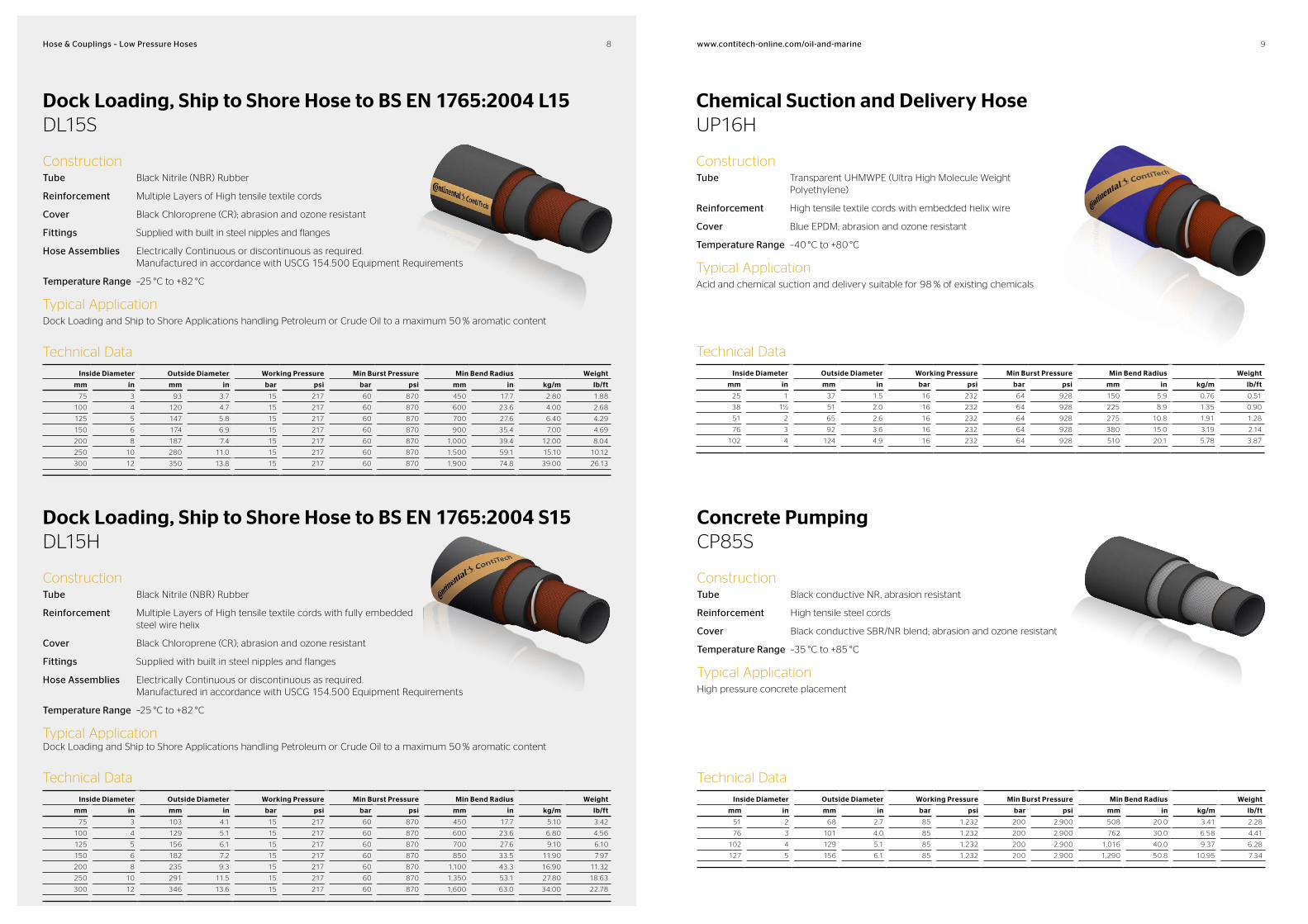
Dock Loading, Ship to Shore Hose to BS EN 1765:2004 L15DL15S
ConstructionTube Black Nitrile (NBR) Rubber
Reinforcement Multiple Layers of High tensile textile cords
Cover Black Chloroprene (CR); abrasion and ozone resistant
Fittings Supplied with built in steel nipples and flanges
Hose Assemblies Electrically Continuous or discontinuous as required. Manufactured in accordance with USCG 154.500 Equipment Requirements
Temperature Range –25 °C to +82 °C
Typical ApplicationDock Loading and Ship to Shore Applications handling Petroleum or Crude Oil to a maximum 50 % aromatic content
Technical Data
Inside Diameter Outside Diameter Working Pressure Min Burst Pressure Min Bend Radius Weight
mm in mm in bar psi bar psi mm in kg/m lb/ft
75 3 93 3.7 15 217 60 870 450 17.7 2.80 1.88
100 4 120 4.7 15 217 60 870 600 23.6 4.00 2.68
125 5 147 5.8 15 217 60 870 700 27.6 6.40 4.29
150 6 174 6.9 15 217 60 870 900 35.4 7.00 4.69
200 8 187 7.4 15 217 60 870 1,000 39.4 12.00 8.04
250 10 280 11.0 15 217 60 870 1,500 59.1 15.10 10.12
300 12 350 13.8 15 217 60 870 1,900 74.8 39.00 26.13
Chemical Suction and Delivery HoseUP16H
ConstructionTube Transparent UHMWPE (Ultra High Molecule Weight
Polyethylene)
Reinforcement High tensile textile cords with embedded helix wire
Cover Blue EPDM; abrasion and ozone resistant
Temperature Range –40 °C to +80 °C
Typical ApplicationAcid and chemical suction and delivery suitable for 98 % of existing chemicals
Technical Data
Inside Diameter Outside Diameter Working Pressure Min Burst Pressure Min Bend Radius Weight
mm in mm in bar psi bar psi mm in kg/m lb/ft
25 1 37 1.5 16 232 64 928 150 5.9 0.76 0.51
38 1½ 51 2.0 16 232 64 928 225 8.9 1.35 0.90
51 2 65 2.6 16 232 64 928 275 10.8 1.91 1.28
76 3 92 3.6 16 232 64 928 380 15.0 3.19 2.14
102 4 124 4.9 16 232 64 928 510 20.1 5.78 3.87
Dock Loading, Ship to Shore Hose to BS EN 1765:2004 S15DL15H
ConstructionTube Black Nitrile (NBR) Rubber
Reinforcement Multiple Layers of High tensile textile cords with fully embedded steel wire helix
Cover Black Chloroprene (CR); abrasion and ozone resistant
Fittings Supplied with built in steel nipples and flanges
Hose Assemblies Electrically Continuous or discontinuous as required. Manufactured in accordance with USCG 154.500 Equipment Requirements
Temperature Range –25 °C to +82 °C
Typical ApplicationDock Loading and Ship to Shore Applications handling Petroleum or Crude Oil to a maximum 50 % aromatic content
Technical Data
Inside Diameter Outside Diameter Working Pressure Min Burst Pressure Min Bend Radius Weight
mm in mm in bar psi bar psi mm in kg/m lb/ft
75 3 103 4.1 15 217 60 870 450 17.7 5.10 3.42
100 4 129 5.1 15 217 60 870 600 23.6 6.80 4.56
125 5 156 6.1 15 217 60 870 700 27.6 9.10 6.10
150 6 182 7.2 15 217 60 870 850 33.5 11.90 7.97
200 8 235 9.3 15 217 60 870 1,100 43.3 16.90 11.32
250 10 291 11.5 15 217 60 870 1,350 53.1 27.80 18.63
300 12 346 13.6 15 217 60 870 1,600 63.0 34.00 22.78
Concrete PumpingCP85S
ConstructionTube Black conductive NR, abrasion resistant
Reinforcement High tensile steel cords
Cover Black conductive SBR/NR blend; abrasion and ozone resistant
Temperature Range –35 °C to +85 °C
Typical ApplicationHigh pressure concrete placement
Technical Data
Inside Diameter Outside Diameter Working Pressure Min Burst Pressure Min Bend Radius Weight
mm in mm in bar psi bar psi mm in kg/m lb/ft
51 2 68 2.7 85 1,232 200 2,900 508 20.0 3.41 2.28
76 3 101 4.0 85 1,232 200 2,900 762 30.0 6.58 4.41
102 4 129 5.1 85 1,232 200 2,900 1,016 40.0 9.37 6.28
127 5 156 6.1 85 1,232 200 2,900 1,290 50.8 10.95 7.34
10 11www.contitechonline.com/oilandmarineHose & Couplings – Low Pressure Hoses
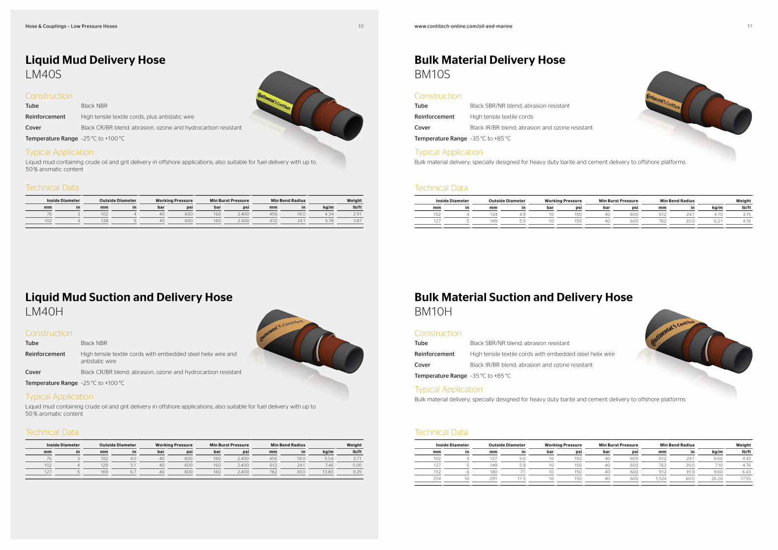
Liquid Mud Delivery HoseLM40S
ConstructionTube Black NBR
Reinforcement High tensile textile cords, plus antistatic wire
Cover Black CR/BR blend; abrasion, ozone and hydrocarbon resistant
Temperature Range –25 °C to +100 °C
Typical ApplicationLiquid mud containing crude oil and grit delivery in offshore applications; also suitable for fuel delivery with up to 50 % aromatic content
Technical Data
Inside Diameter Outside Diameter Working Pressure Min Burst Pressure Min Bend Radius Weight
mm in mm in bar psi bar psi mm in kg/m lb/ft
76 3 102 4 40 600 160 2,400 456 18.0 4.34 2.91
102 4 128 5 40 600 160 2,400 612 24.1 5.78 3.87
Bulk Material Delivery HoseBM10S
ConstructionTube Black SBR/NR blend; abrasion resistant
Reinforcement High tensile textile cords
Cover Black IR/BR blend; abrasion and ozone resistant
Temperature Range –35 °C to +85 °C
Typical ApplicationBulk material delivery; specially designed for heavy duty barite and cement delivery to offshore platforms
Technical Data
Inside Diameter Outside Diameter Working Pressure Min Burst Pressure Min Bend Radius Weight
mm in mm in bar psi bar psi mm in kg/m lb/ft
102 4 124 4.9 10 150 40 600 612 24.1 4.70 3.15
127 5 149 5.9 10 150 40 600 762 30.0 6.21 4.16
Liquid Mud Suction and Delivery HoseLM40H
ConstructionTube Black NBR
Reinforcement High tensile textile cords with embedded steel helix wire and antistatic wire
Cover Black CR/BR blend; abrasion, ozone and hydrocarbon resistant
Temperature Range –25 °C to +100 °C
Typical ApplicationLiquid mud containing crude oil and grit delivery in offshore applications; also suitable for fuel delivery with up to 50 % aromatic content
Technical Data
Inside Diameter Outside Diameter Working Pressure Min Burst Pressure Min Bend Radius Weight
mm in mm in bar psi bar psi mm in kg/m lb/ft
76 3 102 4.0 40 600 160 2,400 456 18.0 5.54 3.71
102 4 129 5.1 40 600 160 2,400 612 24.1 7.46 5.00
127 5 169 6.7 40 600 160 2,400 762 30.0 13.80 9.25
Bulk Material Suction and Delivery HoseBM10H
ConstructionTube Black SBR/NR blend; abrasion resistant
Reinforcement High tensile textile cords with embedded steel helix wire
Cover Black IR/BR blend; abrasion and ozone resistant
Temperature Range –35 °C to +85 °C
Typical ApplicationBulk material delivery; specially designed for heavy duty barite and cement delivery to offshore platforms
Technical Data
Inside Diameter Outside Diameter Working Pressure Min Burst Pressure Min Bend Radius Weight
mm in mm in bar psi bar psi mm in kg/m lb/ft
102 4 127 5.0 10 150 40 600 612 24.1 6.60 4.42
127 5 149 5.9 10 150 40 600 762 30.0 7.10 4.76
152 6 180 7.1 10 150 40 600 912 35.9 9.60 6.43
254 10 291 11.5 10 150 40 600 1,524 60.0 26.20 17.55
12 13www.contitechonline.com/oilandmarineHose & Couplings – Low Pressure Hoses
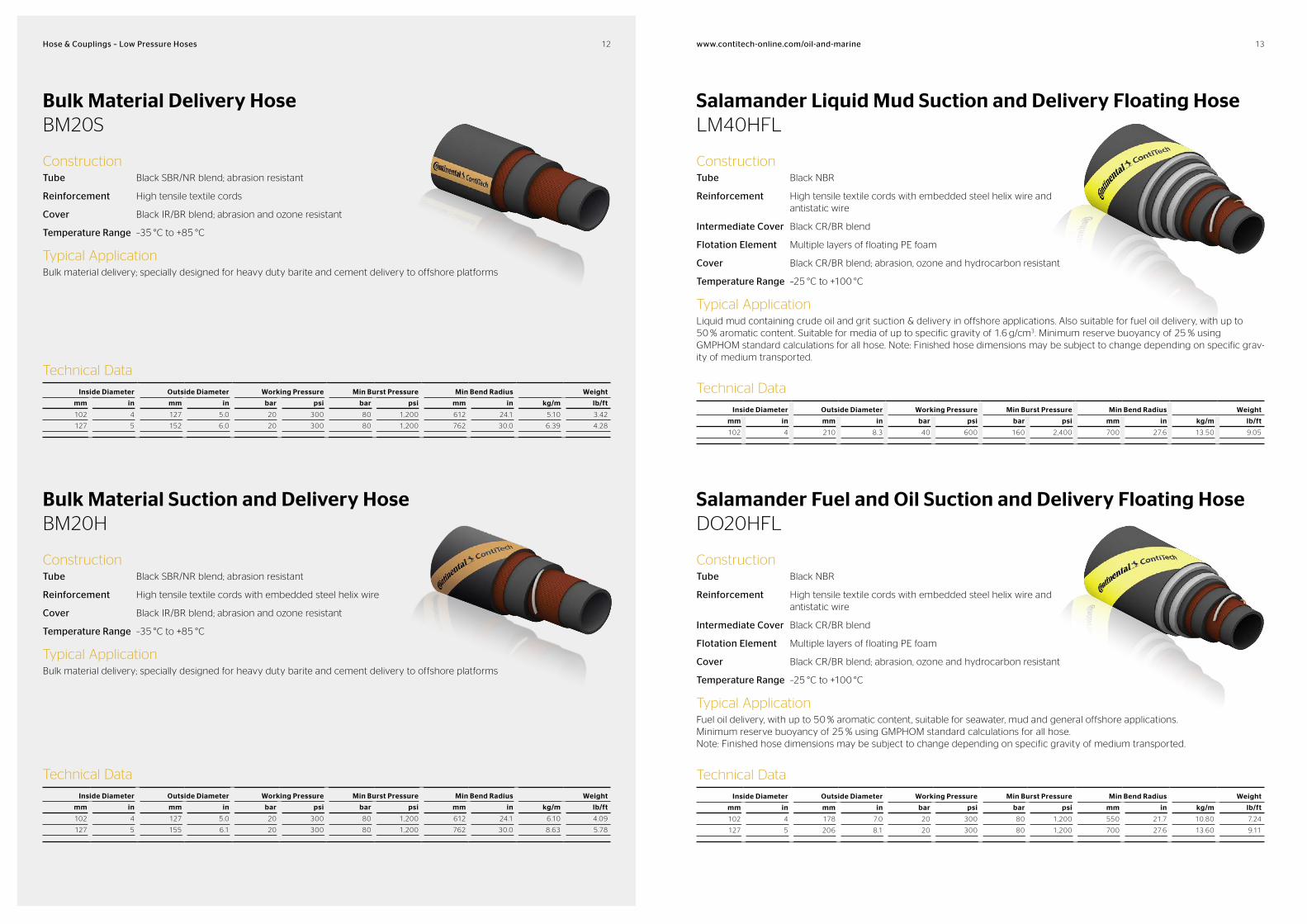
Bulk Material Delivery HoseBM20S
ConstructionTube Black SBR/NR blend; abrasion resistant
Reinforcement High tensile textile cords
Cover Black IR/BR blend; abrasion and ozone resistant
Temperature Range –35 °C to +85 °C
Typical ApplicationBulk material delivery; specially designed for heavy duty barite and cement delivery to offshore platforms
Technical Data
Inside Diameter Outside Diameter Working Pressure Min Burst Pressure Min Bend Radius Weight
mm in mm in bar psi bar psi mm in kg/m lb/ft
102 4 127 5.0 20 300 80 1,200 612 24.1 5.10 3.42
127 5 152 6.0 20 300 80 1,200 762 30.0 6.39 4.28
Bulk Material Suction and Delivery HoseBM20H
ConstructionTube Black SBR/NR blend; abrasion resistant
Reinforcement High tensile textile cords with embedded steel helix wire
Cover Black IR/BR blend; abrasion and ozone resistant
Temperature Range –35 °C to +85 °C
Typical ApplicationBulk material delivery; specially designed for heavy duty barite and cement delivery to offshore platforms
Technical Data
Inside Diameter Outside Diameter Working Pressure Min Burst Pressure Min Bend Radius Weight
mm in mm in bar psi bar psi mm in kg/m lb/ft
102 4 127 5.0 20 300 80 1,200 612 24.1 6.10 4.09
127 5 155 6.1 20 300 80 1,200 762 30.0 8.63 5.78
Salamander Fuel and Oil Suction and Delivery Floating HoseDO20HFL
ConstructionTube Black NBR
Reinforcement High tensile textile cords with embedded steel helix wire and antistatic wire
Intermediate Cover Black CR/BR blend
Flotation Element Multiple layers of floating PE foam
Cover Black CR/BR blend; abrasion, ozone and hydrocarbon resistant
Temperature Range –25 °C to +100 °C
Typical ApplicationFuel oil delivery, with up to 50 % aromatic content, suitable for seawater, mud and general offshore applications. Minimum reserve buoyancy of 25 % using GMPHOM standard calculations for all hose. Note: Finished hose dimensions may be subject to change depending on specific gravity of medium transported.
Technical Data
Inside Diameter Outside Diameter Working Pressure Min Burst Pressure Min Bend Radius Weight
mm in mm in bar psi bar psi mm in kg/m lb/ft
102 4 178 7.0 20 300 80 1,200 550 21.7 10.80 7.24
127 5 206 8.1 20 300 80 1,200 700 27.6 13.60 9.11
Salamander Liquid Mud Suction and Delivery Floating HoseLM40HFL
ConstructionTube Black NBR
Reinforcement High tensile textile cords with embedded steel helix wire and antistatic wire
Intermediate Cover Black CR/BR blend
Flotation Element Multiple layers of floating PE foam
Cover Black CR/BR blend; abrasion, ozone and hydrocarbon resistant
Temperature Range –25 °C to +100 °C
Typical ApplicationLiquid mud containing crude oil and grit suction & delivery in offshore applications. Also suitable for fuel oil delivery, with up to 50 % aromatic content. Suitable for media of up to specific gravity of 1.6 g/cm3. Minimum reserve buoyancy of 25 % using GMPHOM standard calculations for all hose. Note: Finished hose dimensions may be subject to change depending on specific grav-ity of medium transported.
Technical Data
Inside Diameter Outside Diameter Working Pressure Min Burst Pressure Min Bend Radius Weight
mm in mm in bar psi bar psi mm in kg/m lb/ft
102 4 210 8.3 40 600 160 2,400 700 27.6 13.50 9.05

14 15www.contitechonline.com/oilandmarineHose & Couplings – Low Pressure Hoses
Compressed Air HoseAT20S
ConstructionTube Black NBR; oil mist resistant
Reinforcement High tensile textile cords
Cover Yellow CR/BR; abrasion and ozone resistant
Temperature Range –35 °C to +85 °C
Typical ApplicationCompressed air, designed for heavy duty applications
Technical Data
Inside Diameter Outside Diameter Working Pressure Min Burst Pressure Min Bend Radius Weight
mm in mm in bar psi bar psi mm in kg/m lb/ft
10 ⅜ 19 0.7 20 300 60 900 60 2.4 0.23 0.15
13 ½ 23 0.9 20 300 60 900 78 3.1 0.39 0.26
19 ¾ 30 1.2 20 300 60 900 114 4.5 0.60 0.40
25 1 37 1.5 20 300 60 900 150 5.9 0.79 0.53
38 1½ 52 2.0 20 300 60 900 228 9.0 1.36 0.91
51 2 67 2.6 20 300 60 900 306 12.0 2.00 1.34
Salamander Potable Water Suction and Delivery Floating HosePW20HFL
ConstructionTube White UHMWPE (Ultra High Molecular Weight Polyethylene)
Reinforcement High tensile textile cords with embedded steel helix wire and antistatic wire
Intermediate Cover Black CR/BR blend
Flotation Element Multiple layers of floating PE foam
Cover Orange CR/BR blend; abrasion, ozone and hydrocarbon resistant
Temperature Range –35 °C to +100 °C
Typical ApplicationPotable water transfer. Minimum reserve buoyancy of 25 % using GMPHOM standard calculations for all hose. Note: Finished hose dimensions may be subject to change depending on specific gravity of medium transported.
Technical Data
Inside Diameter Outside Diameter Working Pressure Min Burst Pressure Min Bend Radius Weight
mm in mm in bar psi bar psi mm in kg/m lb/ft
76 3 148 5.8 20 300 80 1,200 450 17.7 7.70 5.16
102 4 175 6.9 20 300 80 1,200 550 21.7 10.80 7.24
127 5 203 8.0 20 300 80 1,200 700 27.6 13.60 9.11
Compressed Air HoseAW40S
ConstructionTube Black NBR; oil mist resistant
Reinforcement High tensile steel cords
Cover Yellow CR/BR; abrasion and ozone resistant
Temperature Range –35 °C to +85 °C
Typical ApplicationCompressed air, designed for long lasting service and maximum safety in heavy duty applications
Technical Data
Inside Diameter Outside Diameter Working Pressure Min Burst Pressure Min Bend Radius Weight
mm in mm in bar psi bar psi mm in kg/m lb/ft
38 1½ 52 2.0 40 600 160 2,400 190 7.5 1.65 1.11
51 2 65 2.6 40 600 160 2,400 255 10.0 2.19 1.47
76 3 95 3.7 40 600 160 2,400 380 15.0 4.20 2.81
102 4 121 4.8 40 600 160 2,400 510 20.1 5.80 3.89
Salamander Bulk Material Suction and Delivery Floating HoseBM20HFL
ConstructionTube Black SBR/NR blend, abrasion resistant
Reinforcement High tensile textile cords with embedded steel helix wire
Intermediate Cover Black IR/BR blend
Flotation Element Multiple layers of floating PE foam
Cover Black CR/BR blend; abrasion, ozone and hydrocarbon resistant
Temperature Range –35 °C to +85 °C
Typical ApplicationBulk material delivery; specially designed for heavy duty barite and cement delivery to offshore platforms. Suitable for media of up to specific gravity of 1.6 g/cm3. Minimum reserve buoyancy of 25 % using GMPHOM standard calculations for all hose. Note: Finished hose dimensions may be subject to change depending on specific gravity of medium transported.
Technical Data
Inside Diameter Outside Diameter Working Pressure Min Burst Pressure Min Bend Radius Weight
mm in mm in bar psi bar psi mm in kg/m lb/ft
102 4 205 8.1 20 300 80 1,200 550 21.7 12.40 8.31
127 5 235 9.3 20 300 80 1,200 700 27.6 14.70 9.85
16 17www.contitechonline.com/oilandmarineHose & Couplings – Low Pressure Hoses
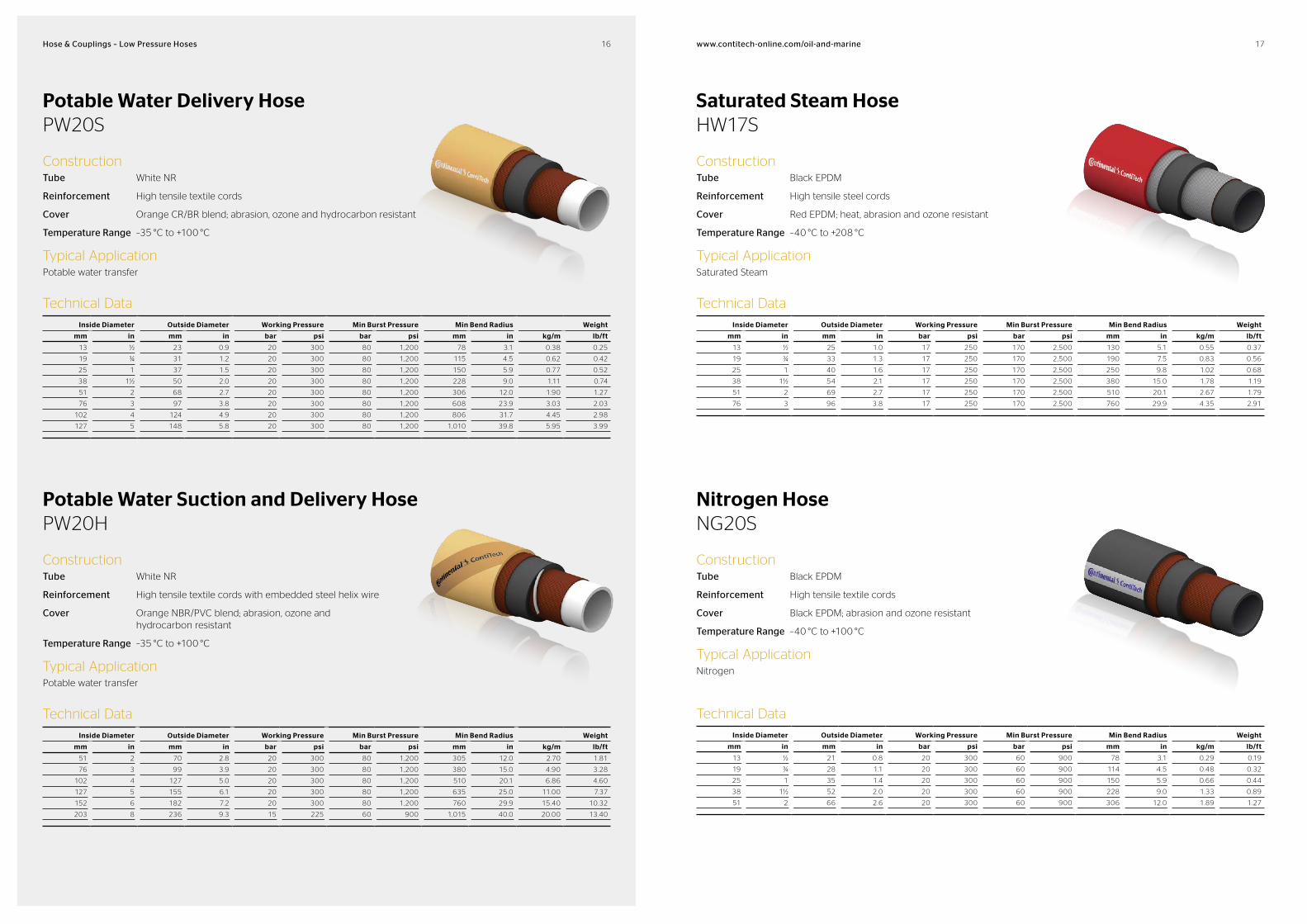
Potable Water Delivery HosePW20S
ConstructionTube White NR
Reinforcement High tensile textile cords
Cover Orange CR/BR blend; abrasion, ozone and hydrocarbon resistant
Temperature Range –35 °C to +100 °C
Typical ApplicationPotable water transfer
Technical Data
Inside Diameter Outside Diameter Working Pressure Min Burst Pressure Min Bend Radius Weight
mm in mm in bar psi bar psi mm in kg/m lb/ft
13 ½ 23 0.9 20 300 80 1,200 78 3.1 0.38 0.25
19 ¾ 31 1.2 20 300 80 1,200 115 4.5 0.62 0.42
25 1 37 1.5 20 300 80 1,200 150 5.9 0.77 0.52
38 1½ 50 2.0 20 300 80 1,200 228 9.0 1.11 0.74
51 2 68 2.7 20 300 80 1,200 306 12.0 1.90 1.27
76 3 97 3.8 20 300 80 1,200 608 23.9 3.03 2.03
102 4 124 4.9 20 300 80 1,200 806 31.7 4.45 2.98
127 5 148 5.8 20 300 80 1,200 1,010 39.8 5.95 3.99
Saturated Steam HoseHW17S
ConstructionTube Black EPDM
Reinforcement High tensile steel cords
Cover Red EPDM; heat, abrasion and ozone resistant
Temperature Range –40 °C to +208 °C
Typical ApplicationSaturated Steam
Technical Data
Inside Diameter Outside Diameter Working Pressure Min Burst Pressure Min Bend Radius Weight
mm in mm in bar psi bar psi mm in kg/m lb/ft
13 ½ 25 1.0 17 250 170 2,500 130 5.1 0.55 0.37
19 ¾ 33 1.3 17 250 170 2,500 190 7.5 0.83 0.56
25 1 40 1.6 17 250 170 2,500 250 9.8 1.02 0.68
38 1½ 54 2.1 17 250 170 2,500 380 15.0 1.78 1.19
51 2 69 2.7 17 250 170 2,500 510 20.1 2.67 1.79
76 3 96 3.8 17 250 170 2,500 760 29.9 4.35 2.91
Potable Water Suction and Delivery HosePW20H
ConstructionTube White NR
Reinforcement High tensile textile cords with embedded steel helix wire
Cover Orange NBR/PVC blend; abrasion, ozone and hydrocarbon resistant
Temperature Range –35 °C to +100 °C
Typical ApplicationPotable water transfer
Technical Data
Inside Diameter Outside Diameter Working Pressure Min Burst Pressure Min Bend Radius Weight
mm in mm in bar psi bar psi mm in kg/m lb/ft
51 2 70 2.8 20 300 80 1,200 305 12.0 2.70 1.81
76 3 99 3.9 20 300 80 1,200 380 15.0 4.90 3.28
102 4 127 5.0 20 300 80 1,200 510 20.1 6.86 4.60
127 5 155 6.1 20 300 80 1,200 635 25.0 11.00 7.37
152 6 182 7.2 20 300 80 1,200 760 29.9 15.40 10.32
203 8 236 9.3 15 225 60 900 1,015 40.0 20.00 13.40
Nitrogen HoseNG20S
ConstructionTube Black EPDM
Reinforcement High tensile textile cords
Cover Black EPDM; abrasion and ozone resistant
Temperature Range –40 °C to +100 °C
Typical ApplicationNitrogen
Technical Data
Inside Diameter Outside Diameter Working Pressure Min Burst Pressure Min Bend Radius Weight
mm in mm in bar psi bar psi mm in kg/m lb/ft
13 ½ 21 0.8 20 300 60 900 78 3.1 0.29 0.19
19 ¾ 28 1.1 20 300 60 900 114 4.5 0.48 0.32
25 1 35 1.4 20 300 60 900 150 5.9 0.66 0.44
38 1½ 52 2.0 20 300 60 900 228 9.0 1.33 0.89
51 2 66 2.6 20 300 60 900 306 12.0 1.89 1.27

18 19www.contitechonline.com/oilandmarineHose & Couplings – Low Pressure Hoses
Multipurpose HoseMP20S
ConstructionTube Black EPDM
Reinforcement High tensile textile cords
Cover Black EPDM; abrasion and ozone resistant
Temperature Range –40 °C to +100 °C
Typical ApplicationWater, seawater, hot water and steam
Technical Data
Inside Diameter Outside Diameter Working Pressure Min Burst Pressure Min Bend Radius Weight
mm in mm in bar psi bar psi mm in kg/m lb/ft
13 ½ 21 0.8 20 300 60 900 78 3.1 0.29 0.19
19 ¾ 28 1.1 20 300 60 900 114 4.5 0.47 0.31
25 1 35 1.4 20 300 60 900 150 5.9 0.66 0.44
38 1½ 52 2.0 20 300 60 900 228 9.0 1.34 0.90
51 2 70 2.8 20 300 60 900 306 12.0 1.87 1.25
Thermoplastic Hose (SAE 100R8)BT9
ConstructionTube Polyelastomer / Nylon
Reinforcement Aramid fibre braid/s
Cover Black, chemical resistant polyurethane (pin pricked for gas applications)
Temperature Range –40 °C to +95 °C
Typical ApplicationSuitable for many industrial gases, (eg. helium, air, heliox – max 25 % O2) and hydraulic oils
Technical Data
Inside Diameter Outside Diameter Working Pressure Min Burst Pressure Min Bend Radius Weight
mm in mm in bar psi bar psi mm in kg/m lb/ft
5 3⁄16 10.4 0.41 345 5,000 1,379 20,000 50 2.0 0.07 0.05
6 ¼ 12.7 0.50 345 5,000 1,379 20,000 50 2.0 0.09 0.06
8 5⁄16 15.0 0.59 293 4,250 1,172 17,000 63 2.5 0.11 0.07
10 ⅜ 16.3 0.64 276 4,000 1,103 16,000 63 2.5 0.13 0.09
12 ½ 20.0 0.79 241 3,500 965 14,000 100 3.9 0.19 0.13
16 5⁄8 23.1 0.91 190 2,750 758 11,000 203 8.0 0.23 0.15
20 ¾ 27.9 1.10 155 2,250 620 9,000 254 10.0 0.26 0.17
25 1 35.8 1.41 138 2,000 552 8,000 305 12.0 0.36 0.24
Water HoseUW20S
ConstructionTube Black NBR
Reinforcement High tensile textile cords
Cover Black NBR; abrasion and ozone resistant
Temperature Range –35 °C to +85 °C
Typical ApplicationWater transfer, designed for heavy duty applications
Technical Data
Inside Diameter Outside Diameter Working Pressure Min Burst Pressure Min Bend Radius Weight
mm in mm in bar psi bar psi mm in kg/m lb/ft
13 ½ 23 0.9 20 300 60 900 78 3.1 0.39 0.26
19 ¾ 30 1.2 20 300 60 900 114 4.5 0.61 0.41
25 1 37 1.5 20 300 60 900 150 5.9 0.79 0.53
51 2 67 2.6 20 300 60 900 306 12.0 2.09 1.40
Thermoplastic Hose (SAE 100R11)BT10
ConstructionTube Nylon 11
Reinforcement Two aramid fibre braids
Cover Chemical resistant nylon 11 (pin pricked for gas applications)
Temperature Range –40 °C to +100 °C
Typical ApplicationSuitable for many industrial gases, (eg. helium, air, heliox – max 25 % O2) and hydraulic oils. Recommended for high pressure applications where low volumetric expansion and corrosion resistance is essential.
Technical Data
Inside Diameter Outside Diameter Working Pressure Min Burst Pressure Min Bend Radius Weight
mm in mm in bar psi bar psi mm in kg/m lb/ft
5 3⁄16 13.5 0.53 689 10,000 2,758 40,000 38 1.5 0.12 0.08
6 ¼ 14.5 0.57 689 10,000 2,758 40,000 64 2.5 0.16 0.11
8 5⁄16 18.3 0.72 552 8,000 2,206 32,000 76 3.0 0.20 0.13
10 ⅜ 19.3 0.76 517 7,500 2,068 30,000 76 3.0 0.25 0.17
13 ½ 22.6 0.89 414 6,000 1,652 24,000 100 3.9 0.35 0.23

20 21www.contitechonline.com/oilandmarineHose & Couplings – Low Pressure Hoses
Thermoplastic Hose (Exceeds the requirements of SAE 100R8)
BT13
ConstructionTube Nylon
Reinforcement Two polyester fibre braids
Cover Polyurethane (pin pricked for gas applications)
Temperature Range –40 °C to +95 °C
Typical ApplicationMultipurpose, including divers breathing, hot water and hydraulics, also suitable for many industrial gases, (eg. helium, air, heliox – max 25 % O2) and hydraulic oils. Recommended for applications where kink resistance is imperative and there is contact with seawater.
Technical Data
Inside Diameter Outside Diameter Working Pressure Min Burst Pressure Min Bend Radius Weight
mm in mm in bar psi bar psi mm in kg/m lb/ft
5 3⁄16 10.5 0.41 345 5,000 1,370 20,000 50 2.0 0.09 0.06
6 ¼ 15.9 0.63 345 5,000 1,370 20,000 50 2.0 0.18 0.12
8 5⁄16 16.7 0.66 290 4,250 1,170 17,000 64 2.5 0.20 0.13
10 ⅜ 19.3 0.76 270 4,000 1,100 16,000 64 2.5 0.23 0.15
13 ½ 22.6 0.89 240 3,500 960 14,000 100 3.9 0.30 0.20
16 5⁄8 25.9 1.02 190 2,750 750 11,000 150 5.9 0.41 0.27
20 ¾ 28.9 1.14 150 2,250 620 9,000 200 7.9 0.44 0.29
25 1 37.1 1.46 140 2,000 550 8,000 250 9.8 0.53 0.36
Single Wire Braid, Thin Cover Hydraulic Hose1SN
ConstructionTube Seamless synthetic rubber
Reinforcement Single high tensile steel wire braid
Cover Black synthetic rubber; weather, oil, fuel and abrasion resistant
Temperature Range –40 °C to +100 °C (+120 °C intermittent)
Meets or exceeds the requirements of SAE J517 100 R1 type AT – EN 853 1SN-ISO 1436. Meets flame resistance acceptance designation US MSHA IC – 152/1 & LOBA
Technical Data
Inside Diameter Outside Diameter Working Pressure Min Burst Pressure Min Bend Radius Weight
mm in mm in bar psi bar psi mm in kg/m lb/ft
4.8 3⁄16 12 0.47 250 3,600 1,000 14,500 90 3.5 0.19 0.13
6.4 ¼ 14 0.55 225 3,250 900 13,050 100 3.9 0.21 0.14
8.0 5⁄16 15 0.59 215 3,100 850 12,350 115 4.5 0.24 0.16
9.5 ⅜ 18 0.71 180 2,600 720 10,450 130 5.1 0.33 0.22
12.7 ½ 21 0.83 160 2,300 640 9,300 180 7.1 0.41 0.27
16.0 5⁄8 24 0.94 130 1,900 520 7,550 200 7.9 0.45 0.30
19.0 ¾ 28 1.10 105 1,500 420 6,000 240 9.4 0.58 0.39
25.4 1 36 1.42 88 1,300 350 5,200 300 11.8 0.88 0.59
32.0 1¼ 44 1.73 63 900 250 3,650 420 16.5 1.23 0.82
38.0 1½ 51 2.01 50 725 200 2,900 500 19.7 1.51 1.01
50.8 2 64 2.52 40 580 160 2,300 630 24.8 1.97 1.32
Thermoplastic Hose (Exceeds the requirements of SAE 100R7)
BT20
ConstructionTube Seamless polyester elastomer
Reinforcement Polyester fibre braid/s
Cover Polyurethane (pin pricked for gas applications)
Temperature Range –40 °C to +95 °C
Typical ApplicationSuitable for many industrial gases, (eg. helium, air, heliox – max 25 % O2) and hydraulic oils. Recommended for high pressure applications where low volumetric expansion and corrosion resistance is essential.
Technical Data
Inside Diameter Outside Diameter Working Pressure Min Burst Pressure Min Bend Radius Weight
mm in mm in bar psi bar psi mm in kg/m lb/ft
3 1⁄8 10.4 0.41 207 3,000 825 12,000 70 2.8 0.07 0.05
6 ¼ 12.7 0.50 190 2,750 750 11,000 70 2.8 0.09 0.06
8 5⁄16 15.0 0.59 172 2,500 690 10,000 89 3.5 0.11 0.07
10 ⅜ 16.3 0.64 155 2,250 620 9,000 127 5.0 0.13 0.09
13 ½ 20.0 0.79 140 2,000 550 8,000 178 7.0 0.19 0.13
16 5⁄8 23.1 0.91 100 1,500 410 6,000 203 8.0 0.23 0.15
20 ¾ 27.9 1.10 90 1,250 345 5,000 254 10.0 0.26 0.17
25 1 35.8 1.41 70 1,000 270 4,000 305 12.0 0.36 0.24
Double Wire Braid, Thin Cover Hydraulic Hose2SN
ConstructionTube Seamless synthetic rubber
Reinforcement Two high tensile steel wire braids
Cover Black synthetic rubber; weather, oil, fuel and abrasion resistant
Temperature Range –40 °C to +100 °C (+120 °C intermittent)
Meets or exceeds the requirements of SAE J517 100 R2 type AT – EN 853 2SN – ISO 1436. Meets flame resistance acceptance designation US MSHA IC – 152/1 & LOBA
Technical Data
Inside Diameter Outside Diameter Working Pressure Min Burst Pressure Min Bend Radius Weight
mm in mm in bar psi bar psi mm in kg/m lb/ft
4.8 3⁄16 14 0.55 415 6,000 1,650 23,950 90 3.5 0.31 0.21
6.4 ¼ 15 0.59 400 5,800 1,600 23,200 100 3.9 0.33 0.22
8.0 5⁄16 17 0.67 350 5,100 1,400 20,300 115 4.5 0.39 0.26
9.5 ⅜ 19 0.75 330 4,800 1,320 19,150 130 5.1 0.50 0.34
12.7 ½ 23 0.91 275 4,000 1,100 15,950 180 7.1 0.59 0.40
16.0 5⁄8 26 1.02 250 3,600 1,000 14,500 200 7.9 0.71 0.48
19.0 ¾ 30 1.18 215 3,100 850 12,350 240 9.4 0.86 0.58
25.4 1 38 1.50 165 2,400 650 9,450 300 11.8 1.28 0.86
32.0 1¼ 49 1.93 125 1,800 500 7,250 420 16.5 2.02 1.35
38.0 1½ 55 2.17 90 1,300 360 5,250 500 19.7 2.32 1.55
50.8 2 68 2.68 80 1,150 320 4,650 630 24.8 2.85 1.91

22 23www.contitechonline.com/oilandmarineHose & Couplings – Low Pressure Hoses
Four Spiral Wire Hydraulic Hose4SP
ConstructionTube Seamless synthetic rubber
Reinforcement Four spirals of high tensile wire
Cover Black synthetic rubber; weather, oil, fuel and abrasion resistant
Temperature Range –40 °C to +100 °C (+120 °C intermittent)
Meets or exceeds the requirements of SAE J517 100 R10 – ESN 856 4SP – ISO 3862. Meets flame resistance acceptance designation US MSHA IC – 152/1 & LOBA
Technical Data
Inside Diameter Outside Diameter Working Pressure Min Burst Pressure Min Bend Radius Weight
mm in mm in bar psi bar psi mm in kg/m lb/ft
10.0 ⅜ 22 0.87 445 6,450 1,780 25,800 180 7.1 0.78 0.52
12.7 ½ 25 0.98 415 6,000 1,660 24,000 230 9.1 0.93 0.62
16.0 5⁄8 28 1.10 350 5,000 1,400 20,300 250 9.8 1.17 0.78
19.0 ¾ 32 1.26 350 5,000 1,400 20,300 300 11.8 1.48 0.99
25.4 1 40 1.57 280 4,000 1,120 16,300 340 13.4 2.02 1.35
32.0 1¼ 51 2.01 210 3,000 840 12,200 460 18.1 3.05 2.04
38.0 1½ 57 2.24 185 2,650 740 10,730 560 22.0 3.52 2.36
50.8 2 70 2.76 165 2,360 660 9,600 660 26.0 5.20 3.48
Four or Six Spiral Wire Hydraulic HoseR13
ConstructionTube Seamless synthetic rubber
Reinforcement Four or six spirals of high tensile wire
Cover Black synthetic rubber; weather, oil, fuel and abrasion resistant
Temperature Range –40 °C to +121 °C
Meets or exceeds the requirements of SAE J517 100 R13 – EN 856 R13 – ISO 3862. Meets flame resistance acceptance designation US MSHA IC – 152/1
Technical Data
Inside Diameter Outside Diameter Working Pressure Min Burst Pressure Min Bend Radius Weight
mm in mm in bar psi bar psi mm in kg/m lb/ft
6.4 ¼ 21 0.81 776 11,250 3,100 44,950 127 5.0 0.93 0.62
9.5 ⅜ 24 0.94 690 10,000 2,760 40,020 152 6.0 1.10 0.74
12.7 ½ 27 1.06 512 7,500 2,070 30,015 200 7.9 1.35 0.90
19.0 ¾ 32 1.26 345 5,000 1,380 20,000 240 9.4 1.65 1.11
25.4 1 39 1.54 345 5,000 1,380 20,000 300 11.8 2.25 1.51
32.0 1¼ 50 1.96 345 5,000 1,380 20,000 420 16.5 3.60 2.41
38.0 1½ 57 2.26 345 5,000 1,380 20,000 500 19.7 4.75 3.18
50.8 2 72 2.83 345 5,000 1,380 20,000 630 24.8 6.90 4.62
Four Spiral Wire Hydraulic Hose4SH
ConstructionTube Seamless synthetic rubber
Reinforcement Four spirals of high tensile wire
Cover Black synthetic rubber; weather, oil, fuel and abrasion resistant
Temperature Range –40 °C to +100 °C (+120 °C intermittent)
Meets or exceeds the requirements of EN 856 4SH and ISO 3862. Meets flame resistance acceptance designation US MSHA IC – 152/1 & LOBA
Technical Data
Inside Diameter Outside Diameter Working Pressure Min Burst Pressure Min Bend Radius Weight
mm in mm in bar psi bar psi mm in kg/m lb/ft
19.0 ¾ 32 1.26 420 6,090 1,680 24,360 280 11.0 1.53 1.03
25.4 1 39 1.54 380 5,510 1,520 22,040 340 13.4 2.06 1.38
32.0 1¼ 46 1.81 345 5,000 1,380 20,000 460 18.1 2.46 1.65
38.0 1½ 54 2.13 290 4,200 1,160 16,820 560 22.0 3.35 2.24
50.8 2 68 2.68 250 3,625 1,000 14,500 700 27.6 4.55 3.05
Hydraulic HoseBX20
ConstructionTube Neoprene/layer of synthetic fabric
Reinforcement Four plies of high tensile steel wire
Cover Synthetic rubber; weather, oil, and abrasion resistant
Temperature Range –40 °C to +121 °C
Technical Data
Inside Diameter Outside Diameter Working Pressure Min Burst Pressure Min Bend Radius Weight
mm in mm in bar psi bar psi mm in kg/m lb/ft
19.0 ¾ 23 0.91 345 5,000 1,380 20,000 240 9.4 1.59 1.07
25.4 1 39 1.54 345 5,000 1,380 20,000 300 11.8 2.20 1.47
32.0 1¼ 50 1.97 345 5,000 1,380 20,000 415 16.3 3.69 2.47
38.0 1½ 57 2.24 345 5,000 1,380 20,000 500 19.7 4.79 3.21
50.8 2 71 2.80 345 5,000 1,380 20,000 635 25.0 7.48 5.01

24 25www.contitechonline.com/oilandmarineHose & Couplings – Low Pressure Hoses
Slim Line Rotary Hydraulic Hose
ConstructionTube Black NBR/CR blend
Reinforcement High strength steel cables and textile plies
Cover Black CR, weather; oil, fuel, ozone and abrasion resistant
Temperature Range –30 °C to +82 °C
Technical Data
Inside Diameter Outside Diameter Working Pressure Min Burst Pressure Min Bend Radius Weight
mm in mm in bar psi bar psi mm in kg/m lb/ft
63.0 2½ 106 4.17 207 3,000 620 9,000 760 29.9 11.20 7.50
76.0 3 119 4.69 207 3,000 620 9,000 910 35.8 13.00 8.71
Blowout Preventor Control HoseFIRESHIELD 5000 Hydraulic Hose
ConstructionTube Black CR rubber
Reinforcement 1⁄4" & 3⁄8", two wire braid. Others 4 or 6 wire spirals
Cover Red flame retardent CR rubber over layers of heat resistant fibre
Temperature Range –40 °C to +100 °C
Fire Rating Lloyds Approved (OD/1000/499) at 700 °C for 5 minutes and API16D compliant
Technical Data
Inside Diameter Outside Diameter Working Pressure Min Burst Pressure Min Bend Radius Weight
mm in mm in bar psi bar psi mm in kg/m lb/ft
6.5 1⁄4 20.0 0.8 345 5,000 1,379 20,000 110 4.3 0.75 0.50
9.5 3⁄8 24.0 0.9 345 5,000 1,379 20,000 150 5.9 0.80 0.54
12.7 1⁄2 30.0 1.2 345 5,000 1,379 20,000 250 9.8 1.22 0.82
19.1 3⁄4 37.0 1.5 345 5,000 1,379 20,000 330 13.0 1.82 1.22
25.4 1 44.0 1.7 345 5,000 1,379 20,000 375 14.8 2.53 1.69
31.7 11⁄4 58.0 2.3 345 5,000 1,379 20,000 460 18.1 4.20 2.81
38.1 11⁄2 63.0 2.5 345 5,000 1,379 20,000 520 20.5 6.29 4.21
50.8 2 77.0 3.0 345 5,000 1,379 20,000 700 27.6 8.90 5.96
Fireshield Fuel and Oil Suction and Delivery HoseDO16HFR
ConstructionTube Black NBR
Reinforcement High tensile textile cords with embedded steel helix wire and antistatic wire
Cover Black CR abrasion, ozone and hydrocarbon resistant over layers
of heat resistant fibre
Temperature Range –25 °C to +100 °C
Fire Rating Lloyds Approved (OSG/1000/499) at 700 °C for 30 minutes.
Typical ApplicationFuel oil suction and delivery, with up to 50% aromatic content, suitable for sea-water, mud and general offshore applications, long lasting in bunkering applications
Technical Data
Inside Diameter Outside Diameter Working Pressure Min Burst Pressure Min Bend Radius Weight
mm in mm in bar psi bar psi mm in kg/m lb/ft
25 1 45 1.8 16 232 64 928 160 6.3 1.48 0.99
38 11⁄2 58 2.3 16 232 64 928 244 9.6 2.15 1.44
51 2 79 3.1 16 232 64 928 300 11.8 4.78 3.20
76 3 107 4.2 16 232 64 928 400 15.7 7.13 4.78
102 4 134 5.3 16 232 64 928 520 20.5 7.46 5.00
127 5 156 6.1 16 232 64 928 1,030 40.6 9.56 6.41
152 6 184 7.2 16 232 64 928 1,140 44.9 14.02 9.39
203 8 242 9.5 16 232 64 928 1,250 49.2 22.54 15.10
Fire Resistant Firewater Deluge HoseFW3 Seawater Delivery
ConstructionTube Black CR rubber
Reinforcement Steel cord layers
Cover Red smooth CR
Temperature Range –30 °C to +100 °C
Fire Rating Lloyds Approved (OD/1000/499) at 700 °C for 30 minutes
Technical Data
Inside Diameter Outside Diameter Working Pressure Min Burst Pressure Min Bend Radius Weight
mm in mm in bar psi bar psi mm in kg/m lb/ft
51 2 79 3.1 21 305 104 1,500 400 15.7 4.78 3.20
76 3 107 4.2 21 305 104 1,500 500 19.7 7.13 4.78
102 4 134 5.3 21 305 104 1,500 600 23.6 7.46 5.00
127 5 156 6.1 21 305 104 1,500 1,030 40.6 9.56 6.41
152 6 184 7.2 21 305 104 1,500 1,140 44.9 14.02 9.39
203 8 242 9.5 21 305 104 1,500 1,250 49.2 22.54 15.10

Low PressureCouplings
Our extensive range of couplings complements our entire range of hoses, and will provide an ideal solution for your coupling requirements. Meeting the highest safety standards, our range in-cludes QR quick disconnect self-sealing couplings, QR74 fire rated coupling and safelock couplings for low pressure applications.
2726 27www.contitechonline.com/oilandmarineHose & Couplings – Low Pressure Couplings
Hose CouplingsSummary
Hose Coupling Type Description ID (mm) ID (in) WP (bar) WP (psi)
Hammer Lug Union 25–206 1–8 414–69 6,000–500
Valved Weaklink Breakaway Coupling 51–127 2–5 20 300
Dry Break Coupling 19–152 ¾–6 10 150
Cam & Groove Coupling 19–152 ¾–6 10–5 150–75
Air Hose Coupling 10–51 ⅜–2 10 150
QR Series
QR5 25 1 350 5,000
QR8 10, 19, 25 ⅜, ¾, 1 20 300
QR9 10, 19, 25 ⅜, ¾, 1 620–276 9,000–4,000
QR10 6,3 ¼ 690 10,000
QR45 10–51 ⅜–2 350–55 5,000–800
QR74 (fire rated) 10–51 ⅜–2 350 5,000
28 29www.contitechonline.com/oilandmarineHose & Couplings – Low Pressure Couplings
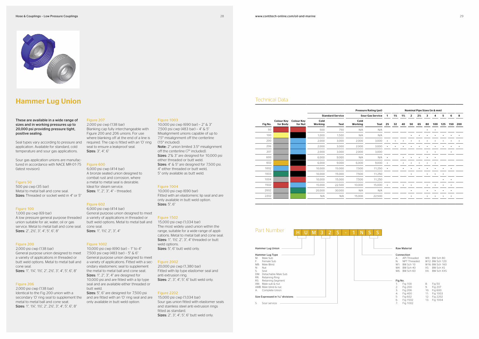
Technical Data
Fig No.Colour Key
for BodyColour Key
for Nut
Pressure Rating (psi) Nominal Pipe Sizes (in & mm)
Standard Service Sour Gas Service 1 11/4 11/2 2 21/2 3 4 5 6 8
Cold Working Test
Cold Working Test 25 32 40 50 65 80 100 125 150 200
50 500 750 N/A N/A • •
100 1,000 1,500 N/A N/A • • • • • • •
200 2,000 3,000 2,000 3,000 • • • • • • • • • •
206 2,000 3,000 2,000 3,000 • • • • • • • • • •
207 2,000 3,000 2,000 3,000 • • •
600 6,000 9,000 N/A N/A • • • • • •
602 6,000 9,000 6,000 9,000 • • • • • •
1002 10,000 15,000 7,500 11,250 • • • • • • • •
1003 10,000 15,000 7,500 11,250 • • • •
1004 10,000 15,000 7,500 11,250 • •
1502 15,000 22,500 10,000 15,000 • • • • • • •
2002 20,000 30,000 N/A N/A • • • • •
2202 N/A N/A 15,000 22,500 • • • • •
Part Number
Hammer Lug Union
Hammer Lug TypeM: Male SubF: Female SubMB: Male BlindN: NutS: SealDM: Detachable Male SubRR: Retaining RingRS: Retaining SegmentAM: Male sub & nutAMB: Male blind & nutA: Complete Union
Size Expressed in 1/16" divisions
S: Sour service
Raw Material
ConnectionA: API ThreadedN: NPT ThreadedW1: BW Sch 10W4: BW Sch 40W6: BW Sch 60
W9: BW Sch 80W12: BW Sch 120W16: BW Sch 160XS: BW Sch XSXX: BW Sch XXS
Fig No.1: Fig 1002: Fig 2003: Fig 2064: Fig 4005: Fig 6026: Fig 15027: Fig 1002
8: Fig 509: Fig 20710: Fig 60011: Fig 100312: Fig 220213: Fig 1004
H U M 3 2 S 1 N S S
Hammer Lug Union
These are available in a wide range of sizes and in working pressures up to 20,000 psi providing pressure tight, positive sealing.
Seal types vary according to pressure and application. Available for standard, cold temperature and sour gas applications.
Sour gas application unions are manufac-tured in accordance with NACE MR-01-75 (latest revision).
Figure 50500 psi cwp (35 bar)Metal to metal ball and cone seal. Sizes: Threaded or socket weld in 4" or 5"
Figure 100 1,000 psi cwp (69 bar)A low pressure general purpose threaded union suitable for air, water, oil or gas service. Metal to metal ball and cone seal. Sizes: 2", 2½", 3", 4", 5", 6", 8"
Figure 200 2,000 psi cwp (138 bar)General purpose union designed to meet a variety of applications in threaded or butt weld options. Metal to metal ball and cone seal. Sizes: 1", 1¼", 1½", 2", 2½", 3", 4", 5", 6", 8"
Figure 206 2,000 psi cwp (138 bar)Identical to the Fig 200 union with a secondary ‘O’ ring seal to supplement the metal to metal ball and cone seat. Sizes: 1", 1¼", 1½", 2", 2½", 3", 4", 5", 6", 8"
Figure 207 2,000 psi cwp (138 bar)Blanking cap fully interchangeable with Figure 200 and 206 unions. For use where blanking off at the end of a line is required. The cap is fitted with an ‘O’ ring seal to ensure a leakproof seal.Sizes: 3", 4", 6"
Figure 6006,000 psi cwp (414 bar)A bronze seated union designed to combat rust and corrosion, where a metal to metal seal is desirable. Ideal for steam service.Sizes: 1", 2", 3", 4" – threaded.
Figure 602 6,000 psi cwp (414 bar)General purpose union designed to meet a variety of applications in threaded or butt weld options. Metal to metal ball and cone seal. Sizes: 1", 1½", 2", 3", 4"
Figure 1002 10,000 psi cwp (690 bar) – 1" to 4"7,500 psi cwp (483 bar) – 5" & 6"General purpose union designed to meet a variety of applications. Fitted with a sec-ondary elastomeric seal to supplement the metal to metal ball and cone seat. Sizes: 1", 2", 3", 4" are designed for 10,000 psi and are fitted with a lip type seal and are available either threaded or butt weld. Sizes: 5", 6" are designed for 7,500 psi and are fitted with an ‘O’ ring seal and are only available in butt weld option.
Figure 100310,000 psi cwp (690 bar) – 2" & 3"7,500 psi cwp (483 bar) – 4" & 5"Misalignment unions capable of up to 7.5° misalignment off the centerline (15° included). Note: 2" union limited 3.5° misalignment off the centerline (7° included). Sizes: 2"& 3" are designed for 10,000 psi either threaded or butt weld. Sizes: 4" & 5" are designed for 7,500 psi. 4" either threaded or butt weld, 5" only available as butt weld.
Figure 1004 10,000 psi cwp (690 bar)Fitted with an elastomeric lip seal and are only available in butt weld option.Sizes: 5", 6"
Figure 1502 15,000 psi cwp (1,034 bar)The most widely used union within the range, suitable for a wide range of appli-cations. Metal to metal ball and cone seal. Sizes: 1", 1½", 2", 3", 4" threaded or butt weld options. Sizes: 5", 6" butt weld only.
Figure 200220,000 psi cwp (1,380 bar)Fitted with lip type elastomer seal and anti extrusion ring. Sizes: 2", 3", 4", 5", 6" butt weld only.
Figure 220215,000 psi cwp (1,034 bar)Sour gas union fitted with elastomer seals and stainless steel anti extrusion rings fitted as standard. Sizes: 2", 3", 4", 5", 6" butt weld only.

30 31www.contitechonline.com/oilandmarineHose & Couplings – Low Pressure Couplings
Valved Weaklink Breakaway Coupling
Materials Stainless Steel 316 or Carbon Steel (internal components stainless steel)
Working Pressure 20 bar (300 psi)
Breakaway Load 3T (other loads available on request)
Design Features • Full range of elastomeric seals available to suit service • 3", 4", 5" and 6" sizes also available with NPT male and hose tail connections • Completely serviceable, all components can be replaced • Also available in unvalved variants
Technical Data
Coupling Size Approximate Length Maximum Diameter NPT Female Thread
mm in mm in mm in mm in
51 2 236 9.3 136 5.4 51 2
76 3 385 15.2 150 5.9 76 3
102 4 385 15.2 175 6.9 102 4
127 5 395 15.6 205 8.1 127 5
Dry Break Coupling
Materials Aluminium, Gunmetal and Stainless Steel 316; Viton seals fitted as standard, alternatives available on request
Available Sizes ¾", 1, 1¼", 1½", 2", 2½", 3", 4", 6"
Working Pressure 10 bar (150 psi)
Design Features • Dry Break Quick Release self sealing couplings are designed for use where it is necessary to connect and disconnect hoses and pipelines under pressure, quickly and without spillage
• They are used for the safe transfer of a diverse range of petroleum products and other liquids, for road and rail tank car loading and off-loading, quayside and offshore bunkering and hose exchange installations in lube oil plants etc
• A complete coupling consists of both a Tank and Hose unit. The Tank unit comprises a body (either flanged or screwed), with a self sealing spring loaded valve, the Hose unit comprises a cam operated self sealing valve assembly, fixed guide sleeve and a swivel hose connector
Operation Coupling operation is by a push and turn action which causes three rollers in the Hose unit to engage with the Tank unit, thus locking and sealing the two halves together, further rotation causes the Hose unit valve to open, allowing flow to commence with minimum pressure drop. On disconnection, the two halves fully close before the couplings separate and spillage is therefore negligible (max 2 cc). To avoid service cross contami-nation, the coupling halves can be supplied c/w a non-interchangeability feature. Both Hose and Tank units are available with BSPP and NPT female threads and the tank unit is also available with integral flange
Part Number
Dry Break Coupling
Coupling TypeH: Hose UnitT: Tank UnitTA: Tank Unit Flanged ASA 150C: Dust CapP: Dust Plug
Seal MaterialV: Viton (standard)
MaterialA1: AluminiumG1: GunmetalSS: Stainless SteelAS: Aluminium Body
c/w Stainless Internals
Connection SizeExpressed in 1/16" divisions
ThreadB: MaleC: Female1: BSP5: NPT
DB H V C5 032 SS
32 33www.contitechonline.com/oilandmarineHose & Couplings – Low Pressure Couplings
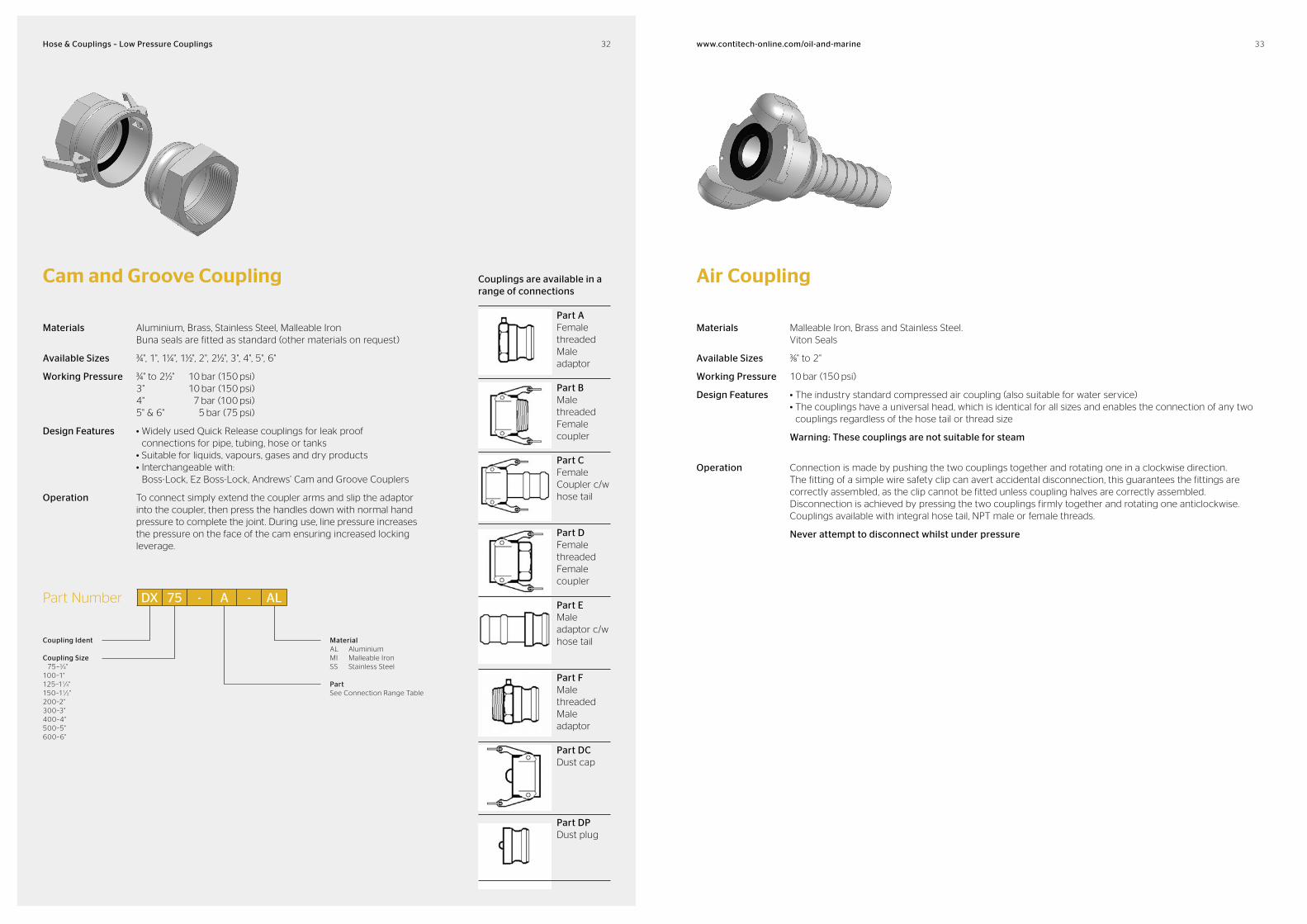
Coupling Ident
Coupling Size 75–3⁄4"100–1"125–11⁄4"150–11⁄2"200–2"300–3"400–4"500–5"600–6"
MaterialAL AluminiumMI Malleable IronSS Stainless Steel
PartSee Connection Range Table
Cam and Groove Coupling
Materials Aluminium, Brass, Stainless Steel, Malleable Iron Buna seals are fitted as standard (other materials on request)
Available Sizes ¾", 1", 1¼", 1½", 2", 2½", 3", 4", 5", 6"
Working Pressure ¾" to 2½" 10 bar (150 psi) 3" 10 bar (150 psi) 4" 7 bar (100 psi) 5" & 6" 5 bar (75 psi)
Design Features • Widely used Quick Release couplings for leak proof connections for pipe, tubing, hose or tanks
• Suitable for liquids, vapours, gases and dry products • Interchangeable with:
Boss-Lock, Ez Boss-Lock, Andrews’ Cam and Groove Couplers
Operation To connect simply extend the coupler arms and slip the adaptor into the coupler, then press the handles down with normal hand pressure to complete the joint. During use, line pressure increases the pressure on the face of the cam ensuring increased locking leverage.
Air Coupling
Materials Malleable Iron, Brass and Stainless Steel. Viton Seals
Available Sizes ⅜" to 2"
Working Pressure 10 bar (150 psi)
Design Features • The industry standard compressed air coupling (also suitable for water service) • The couplings have a universal head, which is identical for all sizes and enables the connection of any two
couplings regardless of the hose tail or thread size
Warning: These couplings are not suitable for steam
Operation Connection is made by pushing the two couplings together and rotating one in a clockwise direction. The fitting of a simple wire safety clip can avert accidental disconnection, this guarantees the fittings are correctly assembled, as the clip cannot be fitted unless coupling halves are correctly assembled. Disconnection is achieved by pressing the two couplings firmly together and rotating one anticlockwise. Couplings available with integral hose tail, NPT male or female threads.
Never attempt to disconnect whilst under pressure
DX 75 A ALPart Number
Part AFemale threaded Male adaptor
Part BMale threaded Female coupler
Part CFemale Coupler c/w hose tail
Part DFemale threaded Female coupler
Part E Male adaptor c/w hose tail
Part FMale threaded Male adaptor
Part DCDust cap
Part DPDust plug
Couplings are available in a range of connections

34 35www.contitechonline.com/oilandmarineHose & Couplings – Low Pressure Couplings
High Pressure Quick Release CouplingQR5 Materials Stainless Steel 316 / 174-PH
Max. Working Pressure 5,000 psi
Min. Burst Pressure 12,500 psi
Design Features • Full range of elastomeric seals available to suit service • Also available with BSPT connectors • Completely serviceable, all components can be replaced
Low Pressure Quick Release CouplingQR8Materials Stainless Steel 316
Design Features • Completely serviceable, all components can be replaced • Also available in hex nut style, other body & seal materials – details on request
Technical Data
Coupling Size NPT Female Thread Coupled Length Female Coupling Length Male Coupling Length Working Pressure
mm in mm in mm in mm in mm in bar psi
9.5 3⁄8 9.5 3⁄8 139 5.488 76 2.986 84 3.317 21 300
19 ¾ 19 ¾ 167 6.585 92 3.640 94 3.706 21 300
25 1 25 1 182 7.175 98 3.840 105 4.126 21 300
Pressure Drop vs Flow Rate
Pre
ssu
re D
rop
(p
si)
1,000
100
10
1
1 10 100 1,000
Flow Rate (GPM)
3⁄8" 3⁄4" 1"
Pressure Drop vs Flow Rate
Pre
ssu
re D
rop
(p
si)
1,000
100
10
1
1 10 100 1,000
Flow Rate (GPM)
1"
Technical Data
Coupling Size NPT Female Thread Coupled Length Female Coupling Length Male Coupling Length Working Pressure
mm in mm in mm in mm in mm in bar psi
25.0 1 25.0 1 148 5.815 116 4.565 83 3.250 345 5,000
36 37www.contitechonline.com/oilandmarineHose & Couplings – Low Pressure Couplings
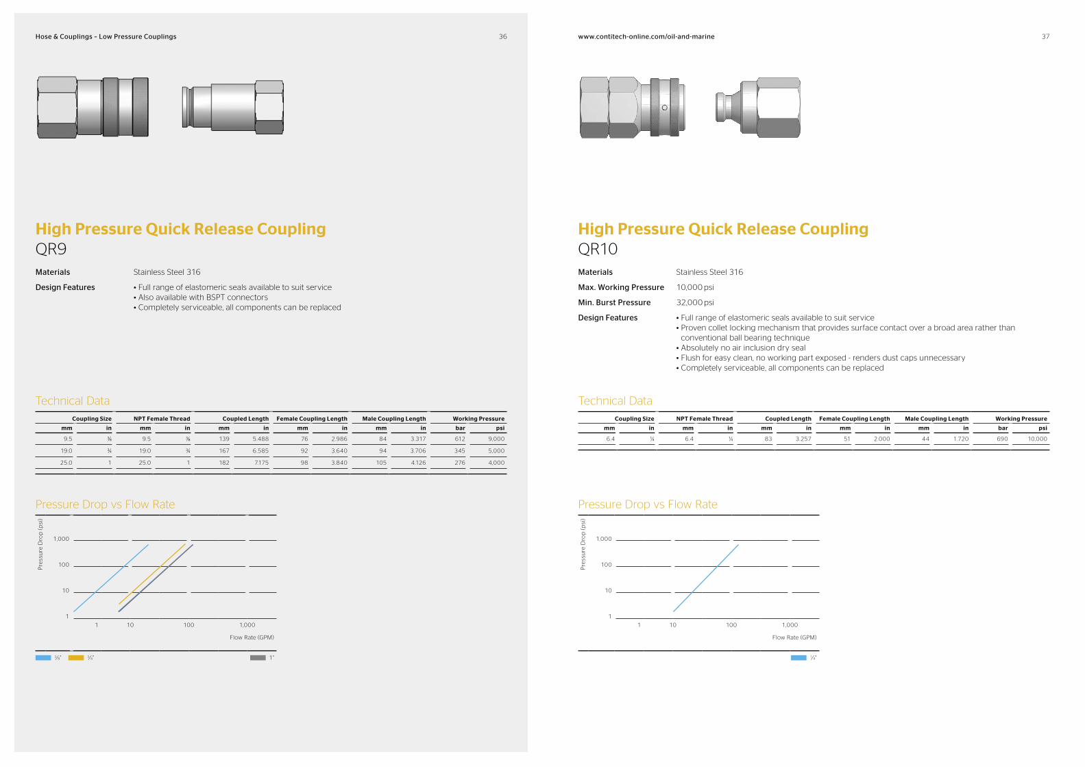
High Pressure Quick Release CouplingQR9Materials Stainless Steel 316
Design Features • Full range of elastomeric seals available to suit service • Also available with BSPT connectors • Completely serviceable, all components can be replaced
High Pressure Quick Release CouplingQR10Materials Stainless Steel 316
Max. Working Pressure 10,000 psi
Min. Burst Pressure 32,000 psi
Design Features • Full range of elastomeric seals available to suit service • Proven collet locking mechanism that provides surface contact over a broad area rather than
conventional ball bearing technique • Absolutely no air inclusion dry seal • Flush for easy clean, no working part exposed - renders dust caps unnecessary • Completely serviceable, all components can be replaced
Technical Data
Coupling Size NPT Female Thread Coupled Length Female Coupling Length Male Coupling Length Working Pressure
mm in mm in mm in mm in mm in bar psi
6.4 ¼ 6.4 ¼ 83 3.257 51 2.000 44 1.720 690 10,000
Pressure Drop vs Flow Rate
Pre
ssu
re D
rop
(p
si)
1,000
100
10
1
1 10 100 1,000
Flow Rate (GPM)
3⁄8" 3⁄4" 1"
Pressure Drop vs Flow Rate
Pre
ssu
re D
rop
(p
si)
1,000
100
10
1
1 10 100 1,000
Flow Rate (GPM)
1⁄4"
Technical Data
Coupling Size NPT Female Thread Coupled Length Female Coupling Length Male Coupling Length Working Pressure
mm in mm in mm in mm in mm in bar psi
9.5 ⅜ 9.5 ⅜ 139 5.488 76 2.986 84 3.317 612 9,000
19.0 ¾ 19.0 ¾ 167 6.585 92 3.640 94 3.706 345 5,000
25.0 1 25.0 1 182 7.175 98 3.840 105 4.126 276 4,000
38 39www.contitechonline.com/oilandmarineHose & Couplings – Low Pressure Couplings
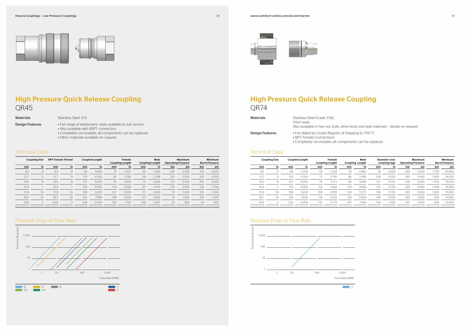
High Pressure Quick Release CouplingQR45Materials Stainless Steel 316
Design Features • Full range of elastomeric seals available to suit service • Also available with BSPT connectors • Completely serviceable, all components can be replaced • Other materials available on request
High Pressure Quick Release CouplingQR74Materials Stainless Steel Grade 316L
Viton seals Also available in hex nut style, other body and seal materials – details on request
Design Features • Fire Rated by Lloyds Register of Shipping to 700 °C • NPT Female Connections • Completely serviceable, all components can be replaced
Technical Data
Coupling Size NPT Female Thread Coupled Length Female Coupling Length
Male Coupling Length
Maximum Operating Pressure
Minimum Burst Pressure
mm in mm in mm in mm in mm in bar psi bar psi
9.5 ⅜ 9.5 ⅜ 92 3.640 74 2.927 48 1.909 241 3,500 310 4,500
12.7 ½ 12.7 ½ 110 4.330 85 3.360 58 2.298 241 3,500 310 4,500
19.0 ¾ 19.0 ¾ 127 5.000 97 3.800 72 2.836 172 2,500 207 3,000
25.4 1 25.4 1 152 6.000 114 4.500 87 3.414 172 2,500 120 1,750
31.8 1¼ 31.8 1¼ 168 6.619 127 5.000 97 3.818 70 1,000 103 1,500
38.1 1½ 38.1 1½ 201 7.894 148 5.842 113 4.462 70 1,000 103 1,500
50.8 2 50.8 2 236 9.304 182 7.147 138 5.437 55 800 34 500
Technical Data
Coupling Size Coupled Length Female Coupling Length
Male Coupling Length
Diameter over coupling lugs
Maximum Operating Pressure
Minimum Burst Pressure
mm in mm in mm in mm in mm in bar psi bar psi
9.5 3⁄8 85 3.334 59 2.332 76 2.983 76 3.000 345 5,000 1,730 26,000
12.7 ½ 110 4.330 71 2.790 86 3.386 108 4.250 345 5,000 1,600 24,000
19.0 ¾ 127 5.000 79 3.111 99 3.898 121 4.750 345 5,000 1,300 19,500
25.4 1 152 6.000 83 3.269 119 4.694 121 4.750 345 5,000 1,200 18,000
31.8 1¼ 168 6.614 100 3.955 134 5.275 146 5.750 345 5,000 1,000 15,000
38.1 1½ 194 7.645 116 4.552 129 5.064 140 5.500 345 5,000 930 14,000
50.8 2 230 9.054 131 5.175 197 7.768 184 7.250 207 3,000 900 13,500
Pressure Drop vs Flow Rate
Pre
ssu
re D
rop
(p
si)
1,000
100
10
1
1 10 100 1,000
Flow Rate (GPM)
⅜" ½" ¾" 1" 1¼" 1½" 2"
Pressure Drop vs Flow Rate
Pre
ssu
re D
rop
(p
si)
1,000
100
10
1
1 10 100 1,000
Flow Rate (GPM)
1⁄4"

www.contitechonline.com/oilandmarine 4140High Pressure Hose & Couplings – High Pressure Hoses
High PressureHose & Couplings
As a world leading manufacturer, ContiTech Oil & Marine boasts decades of experience in the supply of high pressure hoses. Our hoses can be found on installations across the globe, and used for some of the most arduous and demanding applications in topside and subsea services.
Manufactured and designed using state-of-the-art technology, and to the highest quality standards, our hoses guarantee maxi-mum reliability and performance. As such they not only offer
an exceptionally flexible design, but can also withstand external collapse, provide outstanding fatigue properties, offer chemical resistance and heat insulation, and can be supplied in continuous lengths of up to 60 metres.
As the only hose manufacturer in the world to be certified for all relevant API standards – API 7K, API 17K and API 16C, the quality of our hoses is unrivalled within the industry.
High Pressure HosesSummary
Type
Size Range Pressure Range
ApplicationID (mm) ID (in) WP (bar) WP (psi)
API 7K Rotary & Vibrator
(built-in)
51–152 2–6 276–517 4,000–7,500 Mud delivery
Mud jumper
Motion Compensator
Decoking
Water injection
API 7K Rotary & Vibrator
(swaged)
63–102 2.5–4 300–345 4,350–5,000 Mud delivery
Mud jumper
Water injection
API 7KCement
51–102 2–4 345–1035 5,000–15,000 Cementing
Acidizing
Underbalanced Drilling 51–102 2–4 276–517 4,000–7,500 Rotary Drilling
Mud delivery drilling for gas drilling
API 16CChoke & Kill
(Temp B)
51–102 2–4 345–1,035 5,000–15,000 General choke & kill service
Sour service
API 16CChoke & Kill
(Temp U)
51–102 2–4 276-517 5,000–15,000 High temp choke & kill sys-tem
Subsea choke & kill system
Well test
API 17K Production
(for gas service)
51-355 2–14 86–345 1,250–5,000 Live crude oil
Gas export
Gas injection
Gas Lift
Sour service
Topside jumper
Subsea jumper
Tie-in
Riser
Flow line
API 17K Production
(for extreme gas service)
51–127 2–5 414–517 6,000–7,500 Live crude oil
Gas export
Gas injection
Gas Lift
Sour service
Topside jumper
Subsea jumper
Tie-in
Riser
Flow line
API 17K Flexible Lines
(smooth bore with helix stiffening spiral
102–203 4–8 310–414 4,500–6,000 Water injection
Mud delivery
High pressure oil export
High pressure loading

42 43www.contitechonline.com/oilandmarineHigh Pressure Hose & Couplings – High Pressure Hoses
High Pressure Mud and Cement HosesSelection Guide
Relevant standardsAPI Spec. 7K 5th ed. and API RP 7L 1st ed. (2010)
The major revision to API 7K in October 2006 introduced Flexible Specification Levels (FSL) to cover the following hose applications:• FSL 0: Cement hoses – with no pres-
sure pulsation requirement• FSL 1: Rotary and vibrator hoses for
vertical (non-directional) drilling – low-frequency pressure pulsation requirement (NOT recommended for directional drilling)
• FSL 2: Rotary and vibrator hoses for directional drilling high-frequency pressure pulsation requirements recommended for directional drilling with down-linking)
Selection of mud and cement hosesWhen deciding on the specification of your mud and cement hoses, you should consider: pressure rating; maximum ex-pected flow rate (hose ID); hose length; maximum expected operating tempera-ture; pressure pulsations; exposure to chemicals; gas exposure etc.
API Spec. 7K mud hoses should not be used for gas drilling, and must not be exposed to well effluent; for such applica-tions API RP 17B applies.
RecommendationsFor gas and underbalanced drilling use specifically developed mud hoses from ContiTech. If there is any possibility that the rig may be used for directional drilling, then use FSL 2 mud hoses.
Most available high-pressure mud hoses tolerate water-based and oil-based mud, however environmentally friendly mud, e.g. ester mud, may cause problems with some hoses. Similarly, most high-pressure mud hoses have limited resistance to zinc bromide. When ordering a new mud or cement hose, we therefore recommend that you specify any unusual chemicals.
Third party involvement can be arranged at various stages of the manufacture to suit client needs.
In order to avoid over-bending and early failure of high-pressure mud and cement hoses, configuration analysis is recom-mended and can be carried out by our trained engineers using 3-D computer modelling.
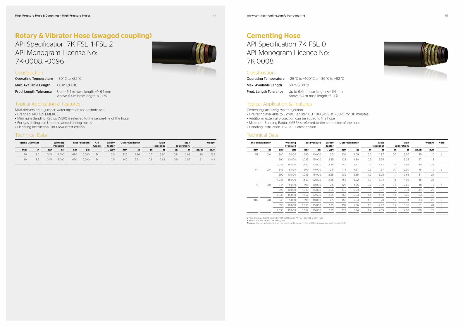
Rotary & Vibrator Hose (built-in coupling)API Specification 7K FSL 1-FSL 2 API Monogram License No: 7K-0008
ConstructionOperating Temperature –25 °C to +100 °C or –30 °C to +82 °C
Max. Available Length 60 m (200 ft)
Prod. Length Tolerance Up to 6.4 m hose length +/– 64 mm Above 6.4 m hose length +/– 1 %
Typical Application & FeaturesMud delivery, mud jumper, motion compensator, decoking, water injection• Fire rating available to Lloyd’s Register OD 1000/499 at 700ºC for 30 minutes• Additional external protection can be added to the hose• Minimum Bending Radius (MBR) is referred to the centre-line of the hose• Handling Instruction: TKO AS0 latest edition• For gas drilling see Underbalanced drilling hoses
Technical Data
Inside Diameter Working Pressure
Test Pressure API Grade
Safety factor
Outer Diameter MBR (storage)
MBR (operation)
Weight Note
mm in bar psi bar psi (· WP) mm in m ft m ft kg/m lb/ft
51 2.0 276 4,000 552 8,000 C 2.5 104 4.09 0.6 1.97 0.7 2.30 15 9.7
345 5,000 690 10,000 D 2.5 104 4.09 0.6 1.97 0.7 2.30 15 9.7
64 2.5 276 4,000 552 8,000 C 2.5 111 4.37 0.6 1.97 0.7 2.30 15 10.1
345 5,000 690 10,000 D 2.5 111 4.37 0.6 1.97 0.7 2.30 15 10.1
517 7,500 1,035 15,000 E 2.5 136 5.35 0.7 2.30 0.8 2.62 31 20.6
76 3.0 276 4,000 552 8,000 C 2.5 126 4.96 0.7 2.30 0.8 2.62 18 12.3
345 5,000 690 10,000 D 2.5 126 4.96 0.7 2.30 0.8 2.62 18 12.3
517 7,500 1,035 15,000 E 2.5 148 5.83 1.0 3.28 1.1 3.61 34 23.1
89 3.5 276 4,000 552 8,000 C 2.5 140 5.51 0.8 2.62 0.9 2.95 21 14.1
345 5,000 690 10,000 D 2.5 140 5.51 0.8 2.62 0.9 2.95 21 14.1
517 7,500 1,035 15,000 E 2.5 162 6.38 1.2 3.94 1.3 4.27 39 25.9
102 4.0 276 4,000 552 8,000 C 2.5 166 6.54 1.0 3.28 1.2 3.94 33 22.0
345 5,000 690 10,000 D 2.5 166 6.54 1.0 3.28 1.2 3.94 33 22.0
517 7,500 1,035 15,000 E 2.5 174 6.85 1.2 3.94 1.4 4.59 42 28.4
127 5.0 345 5,000 690 10,000 D 2.5 213 8.39 1.4 4.59 1.5 4.92 67 45.1
517 7,500 1,035 15,000 E 2.5 213 8.39 1.4 4.59 1.5 4.92 67 45.1
152 6.0 345 5,000 690 7,500 D 2.5 224 8.82 1.5 4.92 1.7 5.58 57 38.3 *
517 7,500 1,035 15,000 E 2.5 248 9.76 1.6 5.25 1.8 5.91 93 62.5 *
* without 7K label
44 45www.contitechonline.com/oilandmarineHigh Pressure Hose & Couplings – High Pressure Hoses
Rotary & Vibrator Hose (swaged coupling)API Specification 7K FSL 1-FSL 2 API Monogram License No: 7K-0008, -0096
ConstructionOperating Temperature –30 °C to +82 °C
Max. Available Length 60 m (200 ft)
Prod. Length Tolerance Up to 6.4 m hose length +/– 64 mm Above 6.4 m hose length +/– 1 %
Typical Application & FeaturesMud delivery, mud jumper, water injection for onshore use• Branded TAURUS EMERGÉ• Minimum Bending Radius (MBR) is referred to the centre-line of the hose• For gas drilling see Underbalanced drilling hoses• Handling Instruction: TKO AS0 latest edition
Technical Data
Inside Diameter Working Pressure
Test Pressure API Grade
Safety factor
Outer Diameter MBR (storage)
MBR (operation)
Weight
mm in bar psi bar psi (· WP) mm in m ft m ft kg/m lb/ft
76 3.0 345 5,000 690 10,000 D 2.5 126 4.96 0.7 2.30 0.8 2.62 18 12.1
89 3.5 345 5,000 690 10,000 D 2.5 140 5.51 0.8 2.62 0.9 2.95 21 14.1
Cementing HoseAPI Specification 7K FSL 0 API Monogram Licence No: 7K-0008
ConstructionOperating Temperature –25 °C to +100 °C or –30 °C to +82 °C
Max. Available Length 60 m (200 ft)
Prod. Length Tolerance Up to 6.4 m hose length +/– 64 mm Above 6.4 m hose length +/– 1 %
Typical Application & FeaturesCementing, acidizing, water injection• Fire rating available to Lloyds Register OD 1000/499 at 700ºC for 30 minutes• Additional external protection can be added to the hose• Minimum Bending Radius (MBR) is referred to the centre-line of the hose• Handling Instruction: TKO AS0 latest edition
Technical Data
Inside Diameter Working Pressure
Test Pressure Safety factor
Outer Diameter MBR (storage)
MBR (operation)
Weight Note
mm in bar psi bar psi (· WP) mm in m ft m ft kg/m lb/ft
51 2.0 345 5,000 690 10,000 2.5 104 4.09 0.6 1.97 0.7 2.30 15 10 a
690 10,000 1,035 15,000 2.25 123 4.84 0.9 2.95 1 3.28 27 18
1,035 15,000 1,552 22,500 2.25 140 5.51 1.1 3.61 1.4 4.59 40 27
64 2.5 345 5,000 690 10,000 2.5 111 4.37 0.6 1.97 0.7 2.30 15 10 a
690 10,000 1,035 15,000 2.25 136 5.35 1.0 3.28 1.1 3.61 31 21
1,035 15,000 1,552 22,500 2.25 153 6.02 1.2 3.94 1.5 4.92 45 31
76 3.0 345 5,000 690 10,000 2.5 126 4.96 0.7 2.30 0.8 2.62 18 12 a
690 10,000 1,035 15,000 2.25 148 5.83 1.1 3.61 1.2 3.94 34 23
1,035 15,000 1,552 22,500 2.25 166 6.54 1.4 4.59 1.6 5.25 53 36
102 4.0 345 5,000 690 10,000 2.5 166 6.54 1.0 3.28 1.2 3.94 33 22 a
690 10,000 1,035 15,000 2.25 192 7.56 1.5 4.92 1.7 5.58 61 41 b
1,035 15,000 1,552 15,000 2.25 222 8.74 1.4 4.59 1.4 4.59 108 73 b
a hose prototype testing covered by API Specification 7K FSL 1 and FSL 2-ISO 14693b without API Specification 7K monogramWarning: After use with acidizing service hoses must be water rinsed until the rinsing water reaches neutral pH
46 47www.contitechonline.com/oilandmarineHigh Pressure Hose & Couplings – High Pressure Hoses
Underbalanced Drilling Hose
ConstructionOperating Temperature –25 °C to +100 °C or –30 °C to +82 °C
Max. Available Length 60 m (200 ft)
Prod. Length Tolerance Up to 6.4 m hose length +/– 64 mm Above 6.4 m hose length +/– 1 %
Typical Application & FeaturesApplications: rotary drilling, mud delivery for gas drilling application, water injection• Test and burst pressure according to API Specification 7K• Fire rating availability to Lloyd’s Register OD 1000/499 at 700ºC for 30 minutes• Additional external protection can be added to the hose• Minimum Bending Radius (MBR) is referred to the centre-line of the hose• Handling Instruction: TKO AS0 latest edition
Technical Data
Inside Diameter Working Pressure
Test Pressure Safety factor
Outer Diameter MBR (storage)
MBR (operation)
Weight Note
mm in bar psi bar psi (· WP) mm in m ft m ft kg/m lb/ft
51 2.0 276 4,000 552 8,000 2.5 94 3.70 0.8 2.62 0.9 2.95 10 6.7
345 5,000 690 10,000 2.5 94 3.70 0.8 2.62 0.9 2.95 10 6.7
64 2.5 276 4,000 552 8,000 2.5 108 4.25 0.9 2.95 1.0 3.28 13 8.7
345 5,000 690 10,000 2.5 110 4.33 0.9 2.95 1.0 3.28 15 10.1
517 7,500 1,035 15,000 2.5 124 4.88 1.0 3.28 1.2 3.94 22 14.8 *
76 3.0 276 4,000 552 8,000 2.5 122 4.80 1.0 3.28 1.2 3.94 15 10.1
345 5,000 690 10,000 2.5 124 4.88 1.0 3.28 1.2 3.94 17 11.4
517 7,500 1,035 15,000 2.5 142 5.59 1.1 3.61 1.3 4.27 31 20.8 *
89 3.5 276 4,000 552 8,000 2.5 138 5.43 1.2 3.94 1.4 4.59 20 13.4
345 5,000 690 10,000 2.5 138 5.43 1.2 3.94 1.4 4.59 20 13.4
517 7,500 1,035 15,000 2.5 156 6.14 1.3 4.27 1.5 4.92 35 23.5 *
102 4.0 276 4,000 552 8,000 2.5 154 6.06 1.3 4.27 1.5 4.92 22 14.8 *
345 5,000 690 10,000 2.5 164 6.46 1.3 4.27 1.5 4.92 32 21.5 *
517 7,500 1,035 15,000 2.5 168 6.61 1.4 4.59 1.6 5.25 39 26.2 *
* hose prototype testing covered by API Specification 7K FSL 1
Flexible Choke and Kill LinesSelection Guide
Relevant standardsAPI Spec. 16C
For flexible choke and kill lines API 16C specification requires complex design verification testing, a series of mechanical tests, including exposure to high concen-tration of H2S, decompressions etc. In addition, a successful fire test (704 °C 30 min) is usually required for topside and land rig applications.
Selection of flexible choke and kill linesWhen deciding on the specification of your flexible choke & kill line, you should consider: pressure rating; maximum expected flow rate (hose ID); hose length; maximum expected operating tempera-ture; exposure to chemicals; water depth (potential collapse of the flexible line); fire safety.
Selection of an unsuitable hose may re-sult in failure in operation, which is likely to occur in the most extreme conditions, i.e. when the choke & kill system is called on to deal with a kick or blow-out situation. For this reason you should only use hoses with full API 16C compliance. For complete peace of mind, we recommend that you ask for third party-witnessed test reports for the particular hose type. The API logo alone does not guarantee that the hose type has undergone proper design verification testing.
We recommend configuration analysis for every flexible choke & kill line application. ContiTech lines have exceptionally low operating bending radius, and preformed flexible lines can be offered to meet the tightest configuration.
Note: Always ensure that all your choke & kill hoses have the API 16C monogram and associated documentation. Only then can you be certain that you have the correct hose for this critical application.
48 49www.contitechonline.com/oilandmarineHigh Pressure Hose & Couplings – High Pressure Hoses
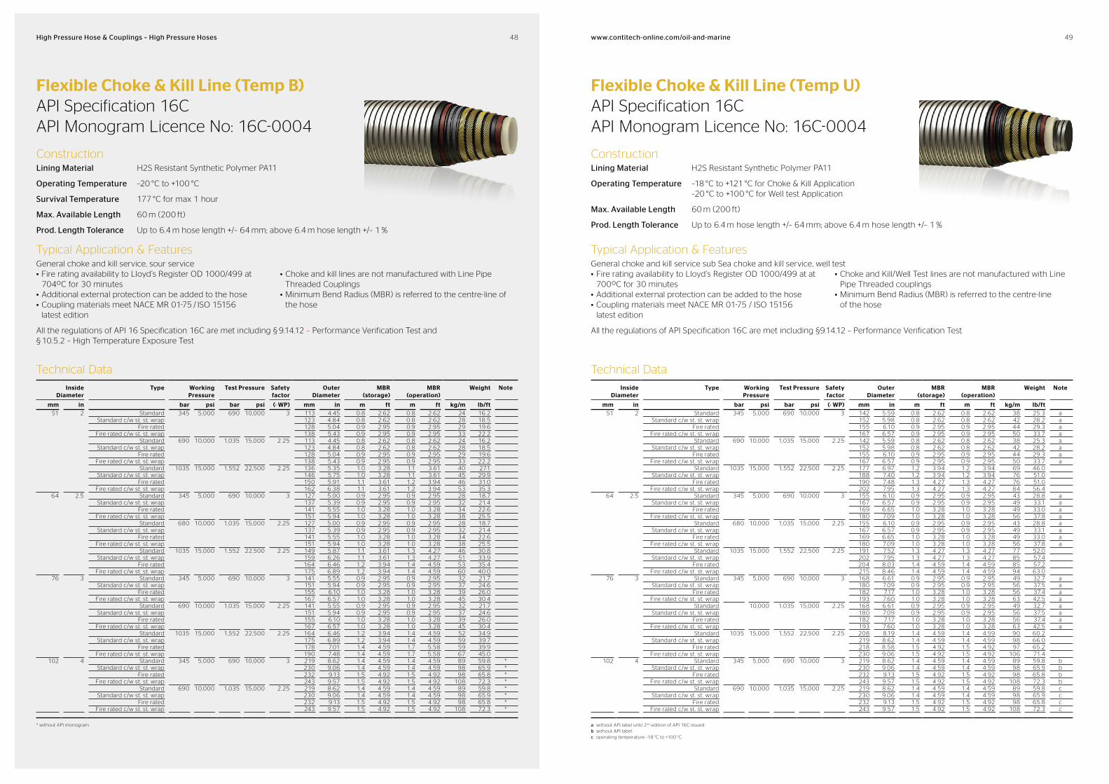
Flexible Choke & Kill Line (Temp B)API Specification 16C API Monogram Licence No: 16C-0004
ConstructionLining Material H2S Resistant Synthetic Polymer PA11
Operating Temperature –20 °C to +100 °C
Survival Temperature 177 °C for max 1 hour
Max. Available Length 60 m (200 ft)
Prod. Length Tolerance Up to 6.4 m hose length +/– 64 mm; above 6.4 m hose length +/– 1 %
Typical Application & FeaturesGeneral choke and kill service, sour service• Fire rating availability to Lloyd’s Register OD 1000/499 at
704ºC for 30 minutes• Additional external protection can be added to the hose• Coupling materials meet NACE MR 01-75 / ISO 15156
latest edition
• Choke and kill lines are not manufactured with Line Pipe Threaded Couplings
• Minimum Bend Radius (MBR) is referred to the centre-line of the hose
All the regulations of API 16 Specification 16C are met including § 9.14.12 – Performance Verification Test and § 10.5.2 – High Temperature Exposure Test
Flexible Choke & Kill Line (Temp U)API Specification 16C API Monogram Licence No: 16C-0004
ConstructionLining Material H2S Resistant Synthetic Polymer PA11
Operating Temperature –18 °C to +121 °C for Choke & Kill Application –20 °C to +100 °C for Well test Application
Max. Available Length 60 m (200 ft)
Prod. Length Tolerance Up to 6.4 m hose length +/– 64 mm; above 6.4 m hose length +/– 1 %
Typical Application & FeaturesGeneral choke and kill service sub Sea choke and kill service, well test • Fire rating availability to Lloyd’s Register OD 1000/499 at at
700ºC for 30 minutes• Additional external protection can be added to the hose• Coupling materials meet NACE MR 01-75 / ISO 15156
latest edition
• Choke and Kill/Well Test lines are not manufactured with Line Pipe Threaded couplings
• Minimum Bend Radius (MBR) is referred to the centre-line of the hose
All the regulations of API Specification 16C are met including §9.14.12 – Performance Verification Test
Technical Data
Inside Diameter
Type Working Pressure
Test Pressure Safety factor
Outer Diameter
MBR (storage)
MBR (operation)
Weight Note
mm in bar psi bar psi (· WP) mm in m ft m ft kg/m lb/ft51 2 Standard 345 5,000 690 10,000 3 113 4.45 0.8 2.62 0.8 2.62 24 16.2
Standard c/w st. st. wrap 123 4.84 0.8 2.62 0.8 2.62 28 18.5Fire rated 128 5.04 0.9 2.95 0.9 2.95 29 19.6
Fire rated c/w st. st. wrap 138 5.43 0.9 2.95 0.9 2.95 33 22.2Standard 690 10,000 1,035 15,000 2.25 113 4.45 0.8 2.62 0.8 2.62 24 16.2
Standard c/w st. st. wrap 123 4.84 0.8 2.62 0.8 2.62 28 18.5Fire rated 128 5.04 0.9 2.95 0.9 2.95 29 19.6
Fire rated c/w st. st. wrap 138 5.43 0.9 2.95 0.9 2.95 33 22.2Standard 1035 15,000 1,552 22,500 2.25 136 5.35 1.0 3.28 1.1 3.61 40 27.1
Standard c/w st. st. wrap 146 5.75 1.0 3.28 1.1 3.61 45 29.9Fire rated 150 5.91 1.1 3.61 1.2 3.94 46 31.0
Fire rated c/w st. st. wrap 162 6.38 1.1 3.61 1.2 3.94 53 35.364 2.5 Standard 345 5,000 690 10,000 3 127 5.00 0.9 2.95 0.9 2.95 28 18.7
Standard c/w st. st. wrap 137 5.39 0.9 2.95 0.9 2.95 32 21.4Fire rated 141 5.55 1.0 3.28 1.0 3.28 34 22.6
Fire rated c/w st. st. wrap 151 5.94 1.0 3.28 1.0 3.28 38 25.5Standard 680 10,000 1,035 15,000 2.25 127 5.00 0.9 2.95 0.9 2.95 28 18.7
Standard c/w st. st. wrap 137 5.39 0.9 2.95 0.9 2.95 32 21.4Fire rated 141 5.55 1.0 3.28 1.0 3.28 34 22.6
Fire rated c/w st. st. wrap 151 5.94 1.0 3.28 1.0 3.28 38 25.5Standard 1035 15,000 1,552 22,500 2.25 149 5.87 1.1 3.61 1.3 4.27 46 30.8
Standard c/w st. st. wrap 159 6.26 1.1 3.61 1.3 4.27 51 33.9Fire rated 164 6.46 1.2 3.94 1.4 4.59 53 35.4
Fire rated c/w st. st. wrap 175 6.89 1.2 3.94 1.4 4.59 60 40.076 3 Standard 345 5,000 690 10,000 3 141 5.55 0.9 2.95 0.9 2.95 32 21.7
Standard c/w st. st. wrap 151 5.94 0.9 2.95 0.9 2.95 37 24.6Fire rated 155 6.10 1.0 3.28 1.0 3.28 39 26.0
Fire rated c/w st. st. wrap 167 6.57 1.0 3.28 1.0 3.28 45 30.4Standard 690 10,000 1,035 15,000 2.25 141 5.55 0.9 2.95 0.9 2.95 32 21.7
Standard c/w st. st. wrap 151 5.94 0.9 2.95 0.9 2.95 37 24.6Fire rated 155 6.10 1.0 3.28 1.0 3.28 39 26.0
Fire rated c/w st. st. wrap 167 6.57 1.0 3.28 1.0 3.28 45 30.4Standard 1035 15,000 1,552 22,500 2.25 164 6.46 1.2 3.94 1.4 4.59 52 34.9
Standard c/w st. st. wrap 175 6.89 1.2 3.94 1.4 4.59 59 39.7Fire rated 178 7.01 1.4 4.59 1.7 5.58 59 39.9
Fire rated c/w st. st. wrap 190 7.48 1.4 4.59 1.7 5.58 67 45.0102 4 Standard 345 5,000 690 10,000 3 219 8.62 1.4 4.59 1.4 4.59 89 59.8 *
Standard c/w st. st. wrap 230 9.06 1.4 4.59 1.4 4.59 98 65.9 *Fire rated 232 9.13 1.5 4.92 1.5 4.92 98 65.8 *
Fire rated c/w st. st. wrap 243 9.57 1.5 4.92 1.5 4.92 108 72.3 *Standard 690 10,000 1,035 15,000 2.25 219 8.62 1.4 4.59 1.4 4.59 89 59.8 *
Standard c/w st. st. wrap 230 9.06 1.4 4.59 1.4 4.59 98 65.9 *Fire rated 232 9.13 1.5 4.92 1.5 4.92 98 65.8 *
Fire rated c/w st. st. wrap 243 9.57 1.5 4.92 1.5 4.92 108 72.3 *
* without API monogram
Technical Data
Inside Diameter
Type Working Pressure
Test Pressure Safety factor
Outer Diameter
MBR (storage)
MBR (operation)
Weight Note
mm in bar psi bar psi (· WP) mm in m ft m ft kg/m lb/ft51 2 Standard 345 5,000 690 10,000 3 142 5.59 0.8 2.62 0.8 2.62 38 25.3 a
Standard c/w st. st. wrap 152 5.98 0.8 2.62 0.8 2.62 42 28.2 aFire rated 155 6.10 0.9 2.95 0.9 2.95 44 29.3 a
Fire rated c/w st. st. wrap 167 6.57 0.9 2.95 0.9 2.95 50 33.7 aStandard 690 10,000 1,035 15,000 2.25 142 5.59 0.8 2.62 0.8 2.62 38 25.3 a
Standard c/w st. st. wrap 152 5.98 0.8 2.62 0.8 2.62 42 28.2 aFire rated 155 6.10 0.9 2.95 0.9 2.95 44 29.3 a
Fire rated c/w st. st. wrap 167 6.57 0.9 2.95 0.9 2.95 50 33.7 aStandard 1035 15,000 1,552 22,500 2.25 177 6.97 1.2 3.94 1.2 3.94 69 46.0
Standard c/w st. st. wrap 188 7.40 1.2 3.94 1.2 3.94 76 51.0Fire rated 190 7.48 1.3 4.27 1.3 4.27 76 51.0
Fire rated c/w st. st. wrap 202 7.95 1.3 4.27 1.3 4.27 84 56.464 2.5 Standard 345 5,000 690 10,000 3 155 6.10 0.9 2.95 0.9 2.95 43 28.8 a
Standard c/w st. st. wrap 167 6.57 0.9 2.95 0.9 2.95 49 33.1 aFire rated 169 6.65 1.0 3.28 1.0 3.28 49 33.0 a
Fire rated c/w st. st. wrap 180 7.09 1.0 3.28 1.0 3.28 56 37.8 aStandard 680 10,000 1,035 15,000 2.25 155 6.10 0.9 2.95 0.9 2.95 43 28.8 a
Standard c/w st. st. wrap 167 6.57 0.9 2.95 0.9 2.95 49 33.1 aFire rated 169 6.65 1.0 3.28 1.0 3.28 49 33.0 a
Fire rated c/w st. st. wrap 180 7.09 1.0 3.28 1.0 3.28 56 37.8 aStandard 1035 15,000 1,552 22,500 2.25 191 7.52 1.3 4.27 1.3 4.27 77 52.0
Standard c/w st. st. wrap 202 7.95 1.3 4.27 1.3 4.27 85 57.4Fire rated 204 8.03 1.4 4.59 1.4 4.59 85 57.2
Fire rated c/w st. st. wrap 215 8.46 1.4 4.59 1.4 4.59 94 63.076 3 Standard 345 5,000 690 10,000 3 168 6.61 0.9 2.95 0.9 2.95 49 32.7 a
Standard c/w st. st. wrap 180 7.09 0.9 2.95 0.9 2.95 56 37.5 aFire rated 182 7.17 1.0 3.28 1.0 3.28 56 37.4 a
Fire rated c/w st. st. wrap 193 7.60 1.0 3.28 1.0 3.28 63 42.5 aStandard 10,000 1,035 15,000 2.25 168 6.61 0.9 2.95 0.9 2.95 49 32.7 a
Standard c/w st. st. wrap 180 7.09 0.9 2.95 0.9 2.95 56 37.5 aFire rated 182 7.17 1.0 3.28 1.0 3.28 56 37.4 a
Fire rated c/w st. st. wrap 193 7.60 1.0 3.28 1.0 3.28 63 42.5 aStandard 1035 15,000 1,552 22,500 2.25 208 8.19 1.4 4.59 1.4 4.59 90 60.2
Standard c/w st. st. wrap 219 8.62 1.4 4.59 1.4 4.59 98 66.0Fire rated 218 8.58 1.5 4.92 1.5 4.92 97 65.2
Fire rated c/w st. st. wrap 230 9.06 1.5 4.92 1.5 4.92 106 71.4102 4 Standard 345 5,000 690 10,000 3 219 8.62 1.4 4.59 1.4 4.59 89 59.8 b
Standard c/w st. st. wrap 230 9.06 1.4 4.59 1.4 4.59 98 65.9 bFire rated 232 9.13 1.5 4.92 1.5 4.92 98 65.8 b
Fire rated c/w st. st. wrap 243 9.57 1.5 4.92 1.5 4.92 108 72.3 bStandard 690 10,000 1,035 15,000 2.25 219 8.62 1.4 4.59 1.4 4.59 89 59.8 c
Standard c/w st. st. wrap 230 9.06 1.4 4.59 1.4 4.59 98 65.9 cFire rated 232 9.13 1.5 4.92 1.5 4.92 98 65.8 c
Fire rated c/w st. st. wrap 243 9.57 1.5 4.92 1.5 4.92 108 72.3 c
a without API label until 2nd edition of API 16C issuedb without API labelc operating temperature –18 °C to +100 °C
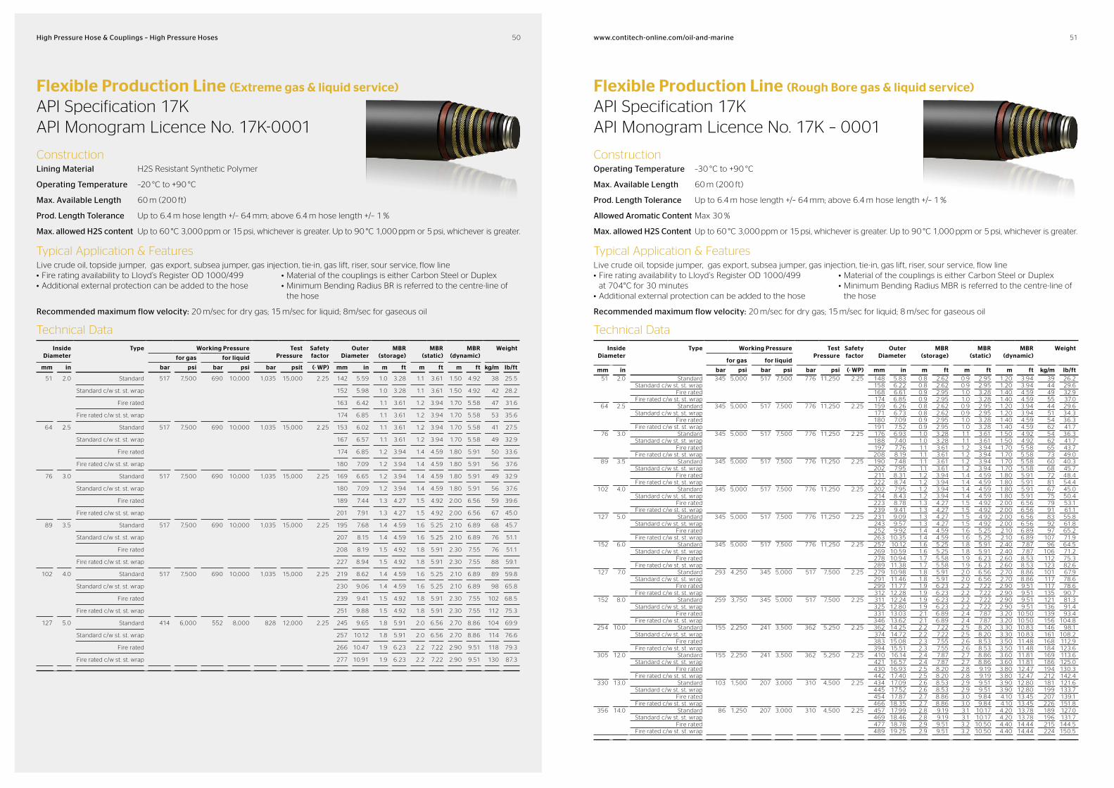
50 51www.contitechonline.com/oilandmarineHigh Pressure Hose & Couplings – High Pressure Hoses
Flexible Production Line (Extreme gas & liquid service)
API Specification 17K API Monogram Licence No. 17K-0001
ConstructionLining Material H2S Resistant Synthetic Polymer
Operating Temperature –20 °C to +90 °C
Max. Available Length 60 m (200 ft)
Prod. Length Tolerance Up to 6.4 m hose length +/– 64 mm; above 6.4 m hose length +/– 1 %
Max. allowed H2S content Up to 60 °C 3,000 ppm or 15 psi, whichever is greater. Up to 90 °C 1,000 ppm or 5 psi, whichever is greater.
Typical Application & FeaturesLive crude oil, topside jumper, gas export, subsea jumper, gas injection, tie-in, gas lift, riser, sour service, flow line• Fire rating availability to Lloyd’s Register OD 1000/499• Additional external protection can be added to the hose
• Material of the couplings is either Carbon Steel or Duplex• Minimum Bending Radius BR is referred to the centre-line of
the hose
Recommended maximum flow velocity: 20 m/sec for dry gas; 15 m/sec for liquid; 8m/sec for gaseous oil
Flexible Production Line (Rough Bore gas & liquid service)
API Specification 17K API Monogram Licence No. 17K – 0001
ConstructionOperating Temperature –30 °C to +90 °C
Max. Available Length 60 m (200 ft)
Prod. Length Tolerance Up to 6.4 m hose length +/– 64 mm; above 6.4 m hose length +/– 1 %
Allowed Aromatic Content Max 30 %
Max. allowed H2S Content Up to 60 °C 3,000 ppm or 15 psi, whichever is greater. Up to 90 °C 1,000 ppm or 5 psi, whichever is greater.
Typical Application & FeaturesLive crude oil, topside jumper, gas export, subsea jumper, gas injection, tie-in, gas lift, riser, sour service, flow line• Fire rating availability to Lloyd’s Register OD 1000/499
at 704°C for 30 minutes• Additional external protection can be added to the hose
• Material of the couplings is either Carbon Steel or Duplex• Minimum Bending Radius MBR is referred to the centre-line of
the hose
Recommended maximum flow velocity: 20 m/sec for dry gas; 15 m/sec for liquid; 8 m/sec for gaseous oil
Technical Data
Inside Diameter
Type Working Pressure Test Pressure
Safety factor
Outer Diameter
MBR (storage)
MBR (static)
MBR (dynamic)
Weight
for gas for liquid
mm in bar psi bar psi bar psit (· WP) mm in m ft m ft m ft kg/m lb/ft
51 2.0 Standard 517 7,500 690 10,000 1,035 15,000 2.25 142 5.59 1.0 3.28 1.1 3.61 1.50 4.92 38 25.5
Standard c/w st. st. wrap 152 5.98 1.0 3.28 1.1 3.61 1.50 4.92 42 28.2
Fire rated 163 6.42 1.1 3.61 1.2 3.94 1.70 5.58 47 31.6
Fire rated c/w st. st. wrap 174 6.85 1.1 3.61 1.2 3.94 1.70 5.58 53 35.6
64 2.5 Standard 517 7,500 690 10,000 1,035 15,000 2.25 153 6.02 1.1 3.61 1.2 3.94 1.70 5.58 41 27.5
Standard c/w st. st. wrap 167 6.57 1.1 3.61 1.2 3.94 1.70 5.58 49 32.9
Fire rated 174 6.85 1.2 3.94 1.4 4.59 1.80 5.91 50 33.6
Fire rated c/w st. st. wrap 180 7.09 1.2 3.94 1.4 4.59 1.80 5.91 56 37.6
76 3.0 Standard 517 7,500 690 10,000 1,035 15,000 2.25 169 6.65 1.2 3.94 1.4 4.59 1.80 5.91 49 32.9
Standard c/w st. st. wrap 180 7.09 1.2 3.94 1.4 4.59 1.80 5.91 56 37.6
Fire rated 189 7.44 1.3 4.27 1.5 4.92 2.00 6.56 59 39.6
Fire rated c/w st. st. wrap 201 7.91 1.3 4.27 1.5 4.92 2.00 6.56 67 45.0
89 3.5 Standard 517 7,500 690 10,000 1,035 15,000 2.25 195 7.68 1.4 4.59 1.6 5.25 2.10 6.89 68 45.7
Standard c/w st. st. wrap 207 8.15 1.4 4.59 1.6 5.25 2.10 6.89 76 51.1
Fire rated 208 8.19 1.5 4.92 1.8 5.91 2.30 7.55 76 51.1
Fire rated c/w st. st. wrap 227 8.94 1.5 4.92 1.8 5.91 2.30 7.55 88 59.1
102 4.0 Standard 517 7,500 690 10,000 1,035 15,000 2.25 219 8.62 1.4 4.59 1.6 5.25 2.10 6.89 89 59.8
Standard c/w st. st. wrap 230 9.06 1.4 4.59 1.6 5.25 2.10 6.89 98 65.8
Fire rated 239 9.41 1.5 4.92 1.8 5.91 2.30 7.55 102 68.5
Fire rated c/w st. st. wrap 251 9.88 1.5 4.92 1.8 5.91 2.30 7.55 112 75.3
127 5.0 Standard 414 6,000 552 8,000 828 12,000 2.25 245 9.65 1.8 5.91 2.0 6.56 2.70 8.86 104 69.9
Standard c/w st. st. wrap 257 10.12 1.8 5.91 2.0 6.56 2.70 8.86 114 76.6
Fire rated 266 10.47 1.9 6.23 2.2 7.22 2.90 9.51 118 79.3
Fire rated c/w st. st. wrap 277 10.91 1.9 6.23 2.2 7.22 2.90 9.51 130 87.3
Technical Data
Inside Diameter
Type Working Pressure Test Pressure
Safety factor
Outer Diameter
MBR (storage)
MBR (static)
MBR (dynamic)
Weight
for gas for liquid
mm in bar psi bar psi bar psi (· WP) mm in m ft m ft m ft kg/m lb/ft51 2.0 Standard 345 5,000 517 7,500 776 11,250 2.25 148 5.83 0.8 2.62 0.9 2.95 1.20 3.94 39 26.2
Standard c/w st. st. wrap 158 6.22 0.8 2.62 0.9 2.95 1.20 3.94 44 29.6Fire rated 168 6.61 0.9 2.95 1.0 3.28 1.40 4.59 49 32.9
Fire rated c/w st. st. wrap 174 6.85 0.9 2.95 1.0 3.28 1.40 4.59 55 37.064 2.5 Standard 345 5,000 517 7,500 776 11,250 2.25 159 6.26 0.8 2.62 0.9 2.95 1.20 3.94 44 29.6
Standard c/w st. st. wrap 171 6.73 0.8 2.62 0.9 2.95 1.20 3.94 51 34.3Fire rated 180 7.09 0.9 2.95 1.0 3.28 1.40 4.59 54 36.3
Fire rated c/w st. st. wrap 191 7.52 0.9 2.95 1.0 3.28 1.40 4.59 62 41.776 3.0 Standard 345 5,000 517 7,500 776 11,250 2.25 176 6.93 1.0 3.28 1.1 3.61 1.50 4.92 54 36.3
Standard c/w st. st. wrap 188 7.40 1.0 3.28 1.1 3.61 1.50 4.92 62 41.7Fire rated 197 7.76 1.1 3.61 1.2 3.94 1.70 5.58 65 43.7
Fire rated c/w st. st. wrap 208 8.19 1.1 3.61 1.2 3.94 1.70 5.58 73 49.089 3.5 Standard 345 5,000 517 7,500 776 11,250 2.25 190 7.48 1.1 3.61 1.2 3.94 1.70 5.58 60 40.3
Standard c/w st. st. wrap 202 7.95 1.1 3.61 1.2 3.94 1.70 5.58 68 45.7Fire rated 211 8.31 1.2 3.94 1.4 4.59 1.80 5.91 72 48.4
Fire rated c/w st. st. wrap 222 8.74 1.2 3.94 1.4 4.59 1.80 5.91 81 54.4102 4.0 Standard 345 5,000 517 7,500 776 11,250 2.25 202 7.95 1.2 3.94 1.4 4.59 1.80 5.91 67 45.0
Standard c/w st. st. wrap 214 8.43 1.2 3.94 1.4 4.59 1.80 5.91 75 50.4Fire rated 223 8.78 1.3 4.27 1.5 4.92 2.00 6.56 79 53.1
Fire rated c/w st. st. wrap 239 9.41 1.3 4.27 1.5 4.92 2.00 6.56 91 61.1127 5.0 Standard 345 5,000 517 7,500 776 11,250 2.25 231 9.09 1.3 4.27 1.5 4.92 2.00 6.56 83 55.8
Standard c/w st. st. wrap 243 9.57 1.3 4.27 1.5 4.92 2.00 6.56 92 61.8Fire rated 252 9.92 1.4 4.59 1.6 5.25 2.10 6.89 97 65.2
Fire rated c/w st. st. wrap 263 10.35 1.4 4.59 1.6 5.25 2.10 6.89 107 71.9152 6.0 Standard 345 5,000 517 7,500 776 11,250 2.25 257 10.12 1.6 5.25 1.8 5.91 2.40 7.87 96 64.5
Standard c/w st. st. wrap 269 10.59 1.6 5.25 1.8 5.91 2.40 7.87 106 71.2Fire rated 278 10.94 1.7 5.58 1.9 6.23 2.60 8.53 112 75.3
Fire rated c/w st. st. wrap 289 11.38 1.7 5.58 1.9 6.23 2.60 8.53 123 82.6127 7.0 Standard 293 4,250 345 5,000 517 7,500 2.25 279 10.98 1.8 5.91 2.0 6.56 2.70 8.86 101 67.9
Standard c/w st. st. wrap 291 11.46 1.8 5.91 2.0 6.56 2.70 8.86 117 78.6Fire rated 299 11.77 1.9 6.23 2.2 7.22 2.90 9.51 117 78.6
Fire rated c/w st. st. wrap 312 12.28 1.9 6.23 2.2 7.22 2.90 9.51 135 90.7152 8.0 Standard 259 3,750 345 5,000 517 7,500 2.25 311 12.24 1.9 6.23 2.2 7.22 2.90 9.51 121 81.3
Standard c/w st. st. wrap 325 12.80 1.9 6.23 2.2 7.22 2.90 9.51 136 91.4Fire rated 331 13.03 2.1 6.89 2.4 7.87 3.20 10.50 139 93.4
Fire rated c/w st. st. wrap 346 13.62 2.1 6.89 2.4 7.87 3.20 10.50 156 104.8254 10.0 Standard 155 2,250 241 3,500 362 5,250 2.25 362 14.25 2.2 7.22 2.5 8.20 3.30 10.83 146 98.1
Standard c/w st. st. wrap 374 14.72 2.2 7.22 2.5 8.20 3.30 10.83 161 108.2Fire rated 383 15.08 2.3 7.55 2.6 8.53 3.50 11.48 168 112.9
Fire rated c/w st. st. wrap 394 15.51 2.3 7.55 2.6 8.53 3.50 11.48 184 123.6305 12.0 Standard 155 2,250 241 3,500 362 5,250 2.25 410 16.14 2.4 7.87 2.7 8.86 3.60 11.81 169 113.6
Standard c/w st. st. wrap 421 16.57 2.4 7.87 2.7 8.86 3.60 11.81 186 125.0Fire rated 430 16.93 2.5 8.20 2.8 9.19 3.80 12.47 194 130.3
Fire rated c/w st. st. wrap 442 17.40 2.5 8.20 2.8 9.19 3.80 12.47 212 142.4330 13.0 Standard 103 1,500 207 3,000 310 4,500 2.25 434 17.09 2.6 8.53 2.9 9.51 3.90 12.80 181 121.6
Standard c/w st. st. wrap 445 17.52 2.6 8.53 2.9 9.51 3.90 12.80 199 133.7Fire rated 454 17.87 2.7 8.86 3.0 9.84 4.10 13.45 207 139.1
Fire rated c/w st. st. wrap 466 18.35 2.7 8.86 3.0 9.84 4.10 13.45 226 151.8356 14.0 Standard 86 1,250 207 3,000 310 4,500 2.25 457 17.99 2.8 9.19 3.1 10.17 4.20 13.78 189 127.0
Standard c/w st. st. wrap 469 18.46 2.8 9.19 3.1 10.17 4.20 13.78 196 131.7Fire rated 477 18.78 2.9 9.51 3.2 10.50 4.40 14.44 215 144.5
Fire rated c/w st. st. wrap 489 19.25 2.9 9.51 3.2 10.50 4.40 14,44 224 150.5

52 53www.contitechonline.com/oilandmarineHigh Pressure Hose & Couplings – High Pressure Hoses
High Pressure Flexible Line (Smooth Bore for Liquid Services)
API Specification 17K API Monogram Licence No. 17K-0001
ConstructionOperating Temperature –25 °C to +90 °C for oily medium without gas
or –25 °C to +60 °C for water
Max. Available Length 60 m (200 ft)
Prod. Length Tolerance Up to 6.4 m hose length +/– 64 mm; above 6.4 m hose length +/– 1 %
Allowed Aromatic Content Max. 40 %
Typical Application & FeaturesWater injection, mud delivery, high pressure oil export, high pressure loading• Fire rating availability to Lloyd’s Register OD 1000/499
at 704°C for 30 minutes• Additional external protection can be added to the hose• Material of couplings either Carbon Steel or Duplex
• Minimum Bend Radius (MBR) is referred to the centre-line of the hose
• Handling Instruction: TKO AS0 latest edition
Recommended max flow velocity: 15 m/sec
Technical Data
Inside Diameter
Type Working Pressure
Test Pressure
Safety factor
Outer Diameter
MBR (storage)
MBR (static)
MBR (dynamic)
Weight
mm in bar psi bar psi (· WP) mm in m ft m ft m ft kg/m lb/ft
102 4.0 Standard 414 6,000 621 9,000 2.25 196 7.72 1.4 4.59 1.6 5.25 2.10 6.89 61 41.0
Fire rated 6,000 9,000 217 8.54 1.5 4.92 1.7 5.58 2.30 7.55 71 47.7
127 5.0 Standard 414 6,000 621 9,000 2.25 222 8.74 1.4 4.59 1.6 5.25 2.10 6.89 72 48.4
Fire rated 6,000 9,000 342 13.46 1.5 4.92 1.7 5.58 2.30 7.55 85 57.1
140 5.5 Standard 414 6,000 621 9,000 2.25 235 9.25 1.5 4.92 1.7 5.58 2.30 7.55 77 51.7
Fire rated 6,000 9,050 255 10.04 1.6 5.25 1.8 5.91 2.40 7.87 91 61.1
152 6.0 Standard 414 6,000 621 9,000 2.25 254 10.00 1.6 5.25 1.8 5.91 2.40 7.87 91 61.1
Fire rated 6,000 9,000 276 10.87 1.7 5.58 1.9 6.23 2.60 8.53 102 68.5
178 7.0 Standard 345 5,000 514 7,500 2.25 284 11.18 1.8 5.91 2.1 6.89 2.70 8.86 109 73.2
Fire rated 5,000 7,500 306 12.05 2 6.56 2.2 7.22 3.00 9.84 127 85.3
203 8.0 Standard 310 4,500 466 6,750 2.25 314 12.36 2 6.56 2.2 7.22 3.00 9.84 120 80.6
Fire rated 4,500 6,750 336 13.23 2.2 7.22 2.4 7.87 3.30 10.83 137 92.1
Customised SolutionsGuide
ContiTech can design hoses for many applications. Welltest hoses, hoses for riser tensioners, and preformed hoses are examples of hoses specially designed to meet specific customer requirements. The company’s R&D and engineering activities are supported by the application of cutting edge software such as 3-D CAD, nonlinear FEA, hydrodynamic analysis, fatigue analysis, inhouse developed technical information systems and simulation facilities. All these capabilities ensure efficiency and the ability to perform quick custom design of special hoses.
ContiTech’s research team and develop-ment engineers are ready to take on and deliver individual and special orders so that we can offer the most suitable flexible pipeline product for the given application.
If the product you need is not included in this catalogue, please do not hesitate to contact a ContiTech sales representative.
Neck ReinforcementCustom designed extra neck reinforce-ment, increasing local bend stiffness to several times of that of the hose body.
Bending StiffnessBend stiffness of the complete hose body can be increased by a factor of 10 or more. In some cases decrease of bend stiffness is also possible.
Location CollarsVulcanized location collars for floaters, preventing slip of the floaters and abrasion on the hose cover.
External Armour for moonpool protectionHigh impact resistant armour, a stainless steel helix embedded in an extra thick rubber cover.
Fire ResistanceHoses can be ordered to withstand 704 °C fire for 30 min (Lloyd’s OD 1000/499).
Sour ServiceHoses and couplings can be ordered to meet NACE MR 01-75 requirements.
Heat TracedFor extreme cold conditions, self regu-lating electric heating cable can be incor-porated in the construction.
Long LengthsNewly developed splicing technology allows long length with continuous vul-canized liner, without potential leak path and heavy intermediate couplings.
Small Bend RadiusVulcanizing the hose in a preformed shape, required by tight configurations Built-in Information technology option to supply hoses equipped with an info chip.
54 55www.contitechonline.com/oilandmarineHigh Pressure Hose & Couplings – High Pressure Hoses
Flexible Riser Tensioner LinesSelection Guide
Relevant standardsTensioner hoses are a relatively new in-dustry development and are not explicitly incorporated in the current API Standards. However the requirements of the hoses in service come into the scope of API 17K.
Riser tensioner hoses transport hydraulic fluid between gas filled accumulators and large hydraulic cylinders. Although they are not in direct contact with pressurized gas, the hydraulic fluid will invariably con-tain dissolved gas after some time, even in configurations with pistons between the gas and the liquid phase. There is a clear risk that this dissolved gas can cause collapse of the hose liner and ultimate failure following decompression.
Selection of flexible riser tensioner linesWhen deciding on the specification of your flexible riser tensioner line, you should consider: pressure rating, maximum ex-pected flow rate (hose ID), hose length, exposure to exposed gas, fire safety, etc. Would there really be tensioner applica-tions where pre-formed could be useful. Since API Spec. 7K does not include gas exposure testing, and does not include hoses with 6" or 8" ID, it should not be considered for tensioner hose applications. We recommend that you request a third party-witnessed gas decompression test report for the purchased hose type or for a similar hose with higher pressure rating.
For every riser tensioner hose application we recommend at least static configura-tion analysis. ContiTech can offer pre-formed flexible lines to meet the tightest configuration. ContiTech tensioner hoses are tested in conformity to API 17K 704 °C / 30 min fire test of the riser tensioner hose to Lloyd’s Register OD/1000/499 rev 1.
For further details regarding the require-ments of riser tensioner hoses, please ask for our manufacturer’s recommendations.
Well-Test LinesSelection Guide
Relevant standardsThere is no recognised industry standard for well-test hoses. However, in view of the typical operating conditions (5000 psi operating pressure or lower, with a very high variation in duration and frequency of operation), the API specifications for choke & kill hoses (API 16C) and produc-tion hoses (API 17K) should be considered. Choke & kill hoses are designed to with-stand short-term high-pressure operation, whilst production hoses must withstand continuous periods of operation with a high risk of rapid decompression. Such decompression can cause collapse of the hose liner as entrained gas, which has entered the hose carcass during the long periods of operation under pressure, permeates back into the hose cavity.
Selection of flexible welltest lines When deciding on the specification of your well-test hose, you should consider: pressure rating, maximum expected flow rate (hose ID), hose length, exposure to exposed gas, duration and frequency of operation, fire safety, etc. When choke and kill hoses are used for well-test application, ContiTech recom-mends that hoses used for well-test operation should have a steel strip wound liner.

56 57www.contitechonline.com/oilandmarineHigh Pressure Hose & Couplings – High Pressure Hoses
Preformed Bonded Flexible HosesSelection Guide
Flexible rubber hoses offer significant design and construction possibilities in the majority of offshore fluid transfer applications. However, fitting a conventional straight hose into a tight or confined space can result in routing compromise, or worse, incorrect installation of the hose leading to damage to the hose through overbending, excessive angular loads etc.
The increasing specifications of today’s drilling rigs and floating production facili-ties result in more and more equipment being packed in to the available space. Installation of a conventional straight rubber hose in a very restricted space can impose a considerable bending mo-ment to keep the hose in the desired configuration.
Such extreme bending moments can in turn transfer high end loads to the coupling and the connected rigid piping and possibly other equipment. These end loads may have a detrimental effect on the service life of connected equipment, such as in-line swivels. For such demanding applications, ContiTech has developed a range of pre-formed flexible hoses to make installation easier, reduce system loads and extend service life.
Preformed Choke and Kill Hoses to API Spec 16CContiTech preformed Choke and Kill hoses can be custom made to fit into tight spaces, such as frequently encountered on BOP stacks. The smaller bend radius relieves the loads on the hose, reducing the likelihood of any potential damage. In addition, the physical size of the BOP stack can be scaled down.
ContiTech preformed Choke and Kill hoses have DNV Design Approval according to API Spec 16C. They are available up to 15,000 psi working pressure and 3" internal diameter. Both temperature rating B (–20 °C to +100 °C) and U (–18 °C to +121 °C) are available.
Preformed Production Hoses to API Spec 17KContiTech offers a family of preformed bonded flexible hoses for continuous ser-vice in high pressure live crude oil and gas transport. The hoses draw on Cont-iTech’s many years’ experience in the de-velopment and manufacture of specialist high pressure hoses for the Oil & Gas in-dustry and use the same basic construc-tion as existing production hoses. They fully comply with API Spec. 17K, yet offer the advantage of considerably smaller bend radius.
The tighter bending radius of ContiTech preformed hoses offers new design op-portunities and greatly reduces the loads, both on end couplings and also adjacent equipment. Ultimately, service life is increased.
In addition, the effective flexible length of the hose has been increased by means of a specially designed hose coupling which is 20 % shorter than the conventional one. The bonding length however re-mains the same, thus retaining the bond strength.
Why use ContiTech Preformed Flexible Hose?
• Easy installation in confined spaces, such as surface production trees, subsea BOP stack
• Extended service life as a result of reduced risk of overbending and reduced stress on hose body and on coupling
• Transfers less load to adjacent equipment or pipe work
• Can be supplied fully compliant with the strict requirements of API standards 17K and 16C
• New short coupling design increases flexible length with no reduction in bonding strength
• Open up new design opportunities to reduce the size and weight of oil field equipment
Gas lift and production jumpers in the crowded
moonpool of a North Sea platform
Hoses can be made with simple 2-D curvature or in complex 3-D shapes.

58 59www.contitechonline.com/oilandmarineHigh Pressure Hose & Couplings– High Pressure Couplings
Basic Coupling Selectionfor High Pressure Hoses
End Fitting Types Description Typical Applications End Fitting Types
AStandard API or
GOST line pipe thread
Rotary and vibrator, Cementing,
Decoking, Mud delivery hoses
BFlanges with API or
GOST line pipe thread
Rotary and vibrator, Cementing,
Decoking, Mud delivery hoses
CHammer lug union with
line pipe thread
Rotary and vibrator, Cementing,
Decoking, Mud delivery hoses
D Hammer lug union male and nut subFor every hose type
for top-side application without gas service
EHammer lug union
female sub
For every hose type for top-side application
without gas service
F Flanges API type 17SVChoke and kill hoses, Flow lines for subsea
application
GFlanges API Spec. 6A or
ASME (ANSI) B 16.5For every hose type
HLapped joint flanges ASME (ANSI) B 16.5
For every hose type
Other end fittings are available on request.
End Fitting Types Description Typical Applications End Fitting Types
IAPI type 16BX integral hub
connectors with in-house type clampFor every hose type
J Techlok type hub For every hose type
KHammer lug union with
line pipe thread For every hose type
L Unibolt plain hub with nut Rotary and vibrator
M Unibolt lug hub Rotary and vibrator
NSwaged coupling
Standard API or GOST line pipe thread
Rotary and vibrator, Cementing,
Decoking, Mud delivery hoses
OSwaged coupling
Hammer lug union male and nut sub
Rotary and vibrator, Cementing,
Decoking, Mud delivery hoses
PSpecial reducer for API or
GOST line pipe threadFor every line pipe
threaded hoses
Other end fittings are available on request.
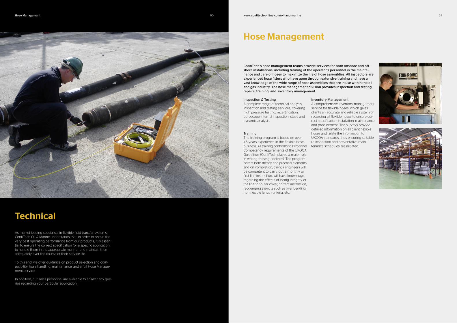
Technical
As market-leading specialists in flexible fluid transfer systems, ContiTech Oil & Marine understands that, in order to obtain the very best operating performance from our products, it is essen-tial to ensure the correct specification for a specific application, to handle them in the appropriate manner and maintain them adequately over the course of their service life.
To this end, we offer guidance on product selection and com-patibility, hose handling, maintenance, and a full Hose Manage-ment service.
In addition, our sales personnel are available to answer any que-ries regarding your particular application.
6060Hose Managemant www.contitechonline.com/oilandmarine 61
Hose Management
ContiTech’s hose management teams provide services for both onshore and offshore installations, including training of the operator’s personnel in the maintenance and care of hoses to maximize the life of hose assemblies. All inspectors are experienced hose fitters who have gone through extensive training and have a vast knowledge of the wide range of hose assemblies that are in use within the oil and gas industry. The hose management division provides inspection and testing, repairs, training, and inventory management.
Inspection & TestingA complete range of technical analysis, inspection and testing services, covering high pressure testing, recertification, boroscope internal inspection, static and dynamic analysis.
TrainingThe training program is based on over 45 years experience in the flexible hose business. All training conforms to Personnel Competency requirements of the UKOOA Guidelines (ContiTech played a major role in writing these guidelines). The program covers both theory and practical elements and on completion, client’s engineers will be competent to carry out 3-monthly or first line inspection, will have knowledge regarding the effects of losing integrity of the liner or outer cover, correct installation, recognizing aspects such as over bending, non-flexible length criteria, etc.
Inventory ManagementA comprehensive inventory management service for flexible hoses, which gives clients an accurate and reliable system of recording all flexible hoses to ensure cor-rect specification, installation, maintenance and procurement. The surveys provide detailed information on all client flexible hoses and relate the information to UKOOA standards, thus ensuring suitable re-inspection and preventative main-tenance schedules are initiated.
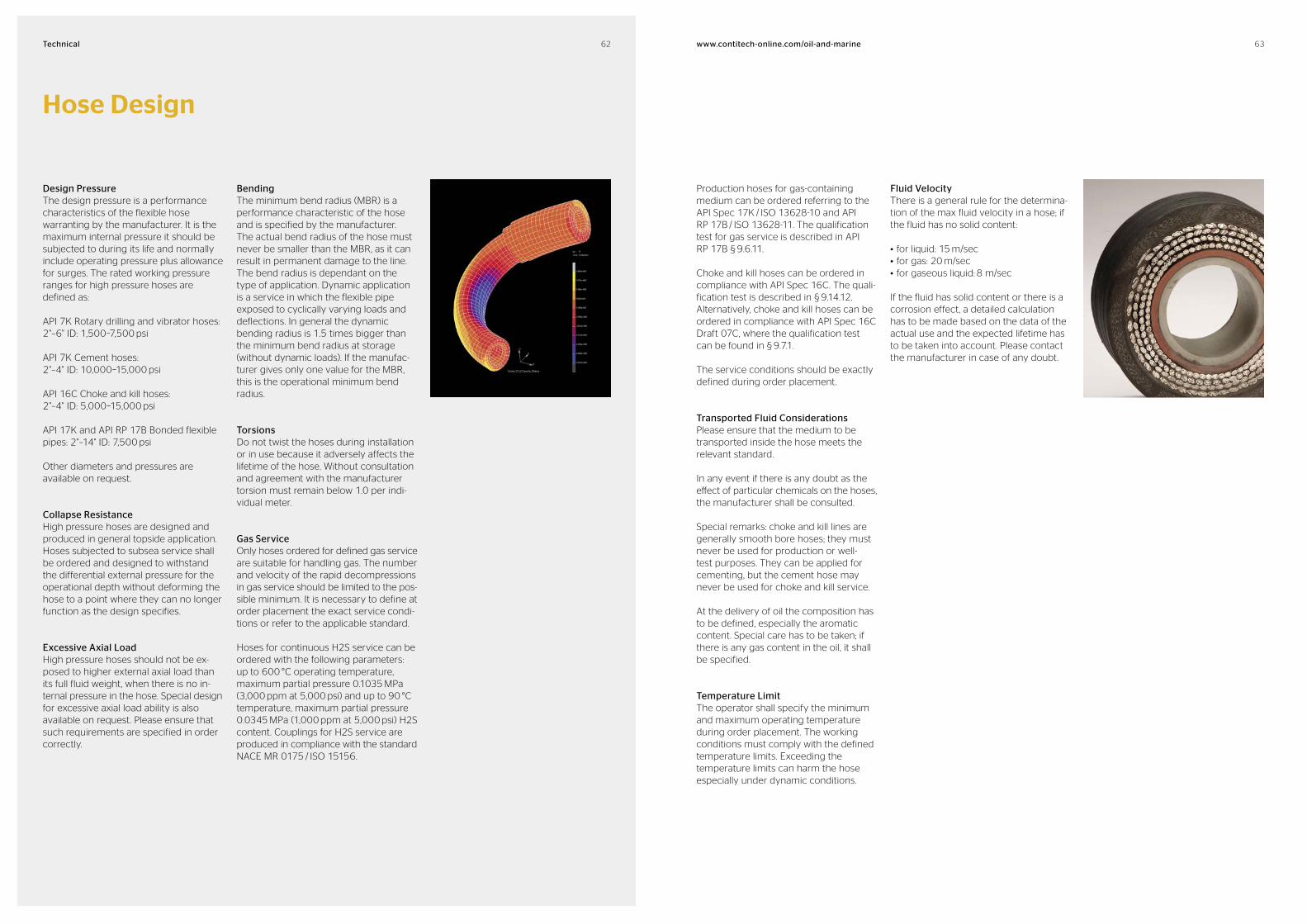
62 63www.contitechonline.com/oilandmarineTechnical
Hose Design
Design PressureThe design pressure is a performance characteristics of the flexible hose warranting by the manufacturer. It is the maximum internal pressure it should be subjected to during its life and normally include operating pressure plus allowance for surges. The rated working pressure ranges for high pressure hoses are defined as:
API 7K Rotary drilling and vibrator hoses: 2"–6" ID: 1,500–7,500 psi
API 7K Cement hoses: 2"–4" ID: 10,000–15,000 psi
API 16C Choke and kill hoses: 2"–4" ID: 5,000–15,000 psi
API 17K and API RP 17B Bonded flexible pipes: 2"–14" ID: 7,500 psi
Other diameters and pressures are available on request.
Collapse ResistanceHigh pressure hoses are designed and produced in general topside application. Hoses subjected to subsea service shall be ordered and designed to withstand the differential external pressure for the operational depth without deforming the hose to a point where they can no longer function as the design specifies.
Excessive Axial LoadHigh pressure hoses should not be ex-posed to higher external axial load than its full fluid weight, when there is no in-ternal pressure in the hose. Special design for excessive axial load ability is also available on request. Please ensure that such requirements are specified in order correctly.
BendingThe minimum bend radius (MBR) is a performance characteristic of the hose and is specified by the manufacturer. The actual bend radius of the hose must never be smaller than the MBR, as it can result in permanent damage to the line. The bend radius is dependant on the type of application. Dynamic application is a service in which the flexible pipe exposed to cyclically varying loads and deflections. In general the dynamic bending radius is 1.5 times bigger than the minimum bend radius at storage (without dynamic loads). If the manufac-turer gives only one value for the MBR, this is the operational minimum bend radius.
TorsionsDo not twist the hoses during installation or in use because it adversely affects the lifetime of the hose. Without consultation and agreement with the manufacturer torsion must remain below 1.0 per indi-vidual meter.
Gas ServiceOnly hoses ordered for defined gas service are suitable for handling gas. The number and velocity of the rapid decompressions in gas service should be limited to the pos-sible minimum. It is necessary to define at order placement the exact service condi-tions or refer to the applicable standard.
Hoses for continuous H2S service can be ordered with the following parameters: up to 600 °C operating temperature, maximum partial pressure 0.1035 MPa (3,000 ppm at 5,000 psi) and up to 90 °C temperature, maximum partial pressure 0.0345 MPa (1,000 ppm at 5,000 psi) H2S content. Couplings for H2S service are produced in compliance with the standard NACE MR 0175 / ISO 15156.
Production hoses for gas-containing medium can be ordered referring to the API Spec 17K / ISO 13628-10 and API RP 17B / ISO 13628-11. The qualification test for gas service is described in API RP 17B § 9.6.11.
Choke and kill hoses can be ordered in compliance with API Spec 16C. The quali-fication test is described in § 9.14.12.Alternatively, choke and kill hoses can be ordered in compliance with API Spec 16C Draft 07C, where the qualification test can be found in § 9.7.1.
The service conditions should be exactly defined during order placement.
Transported Fluid ConsiderationsPlease ensure that the medium to be transported inside the hose meets the relevant standard.
In any event if there is any doubt as the effect of particular chemicals on the hoses, the manufacturer shall be consulted.
Special remarks: choke and kill lines are generally smooth bore hoses; they must never be used for production or well- test purposes. They can be applied for cementing, but the cement hose may never be used for choke and kill service.
At the delivery of oil the composition has to be defined, especially the aromatic content. Special care has to be taken; if there is any gas content in the oil, it shall be specified.
Temperature LimitThe operator shall specify the minimum and maximum operating temperature during order placement. The working conditions must comply with the defined temperature limits. Exceeding the temperature limits can harm the hose especially under dynamic conditions.
Fluid VelocityThere is a general rule for the determina-tion of the max fluid velocity in a hose; if the fluid has no solid content:
• for liquid: 15 m/sec• for gas: 20 m/sec• for gaseous liquid: 8 m/sec
If the fluid has solid content or there is a corrosion effect, a detailed calculation has to be made based on the data of the actual use and the expected lifetime has to be taken into account. Please contact the manufacturer in case of any doubt.

64 65www.contitechonline.com/oilandmarineTechnical
Aromatic Solvents Benzene, Naphthalene, Cumene, P-Cumene, Toluene, Xylene, Cresol, Styrene, Cyclohexane
Aliphatic Solvents Propane, Butane, Pentane, Hexane, Heptane, Dipentene
Halogenous Solvents Chloroform, Dichlorobenzene, Dichloroethylene, Methylen Bromid, Methylen Chloride, Benzyl Chloride, Carbon Tetrachloride, Trichlorethylene, Carbon Disulphide, Turpentine, Perchlorethylene, Dichlorethane
Ketonic Solvents Acetone, Methyl Ketone, Isobutyl Ketone, Methyl Ethyl Ketone, Methyl Isobutyl Ketone
Ester Solvents Butyl Acetate, Methyl Acetate, Amyl Acetate, Isobutyl Acetate
Alcohols Methyl, Ethyl, Butyl, Amyl, Isopropyl, Decyl, Isobutyl, Diacetone, Ethyl Hexanol
Amines Aniline, Ethylene Diamine, Diethanol Amine, Triethanolamine, Dimethylamine, Monoethanolamine
Ab
rasi
on
Lo
w T
em
pe
ratu
re
We
ath
er
resi
sta
nt
Ozo
ne
Re
sist
an
t
He
at
resi
sta
nt
Oil
re
sist
an
t
Fue
l re
sist
an
t
Ch
em
ica
l re
sist
an
t
Pe
tro
leu
m f
luid
re
sist
an
t
Aro
ma
tic
resi
sta
nt
Elastomer Material
CR Chloroprene Rubber ++ ++ ++ + + + +
EPR/EPDM Ethylene Propylene Polymer ++ ++ ++ – +
IR Isoprene Rubber ++ ++ – –
NBR Nitrile Butadiene Rubber ++ + ++ ++ ++ +
NBR-PVC NBR/Polyvinyle Chloride ++ + ++
NR Natural Rubber ++ ++ – –
SBR Styrene Butadiene Rubber ++ + – –
++ excellent property+ moderate property– poor property
Properties
Rubber Properties
Solvent Information
Hose Design
Accidental LoadIf the hose has been the subject of accidental load outside of the operating envelope (e.g. higher temperature, ex-treme flow velocity with abrasive fluid, collapse due to irregular outer force, elongation due to extreme axial load, etc.) it should be replaced.
WeldingNo post welding is allowed on the couplings of the hose.
Handling, Transportation & InstallationWhen a hose has to be lifted from a reel or packing crate, precautions should be taken to ensure that it will not be damaged by dragging it on the floor, against sharp edges of the handling equipment or by unacceptable torsional/bending loading. The flexible pipe should be securely fastened to its reel or packing crate. The end fittings require additional fastening by means of textile bands.
It is recommended to order the hoses with lifting collars and to use them for installation. Never lift the hose in a reverse “U” shape using one band in the middle as this can cause damage.
If the hose was delivered in a crate it should be removed from the crate by hand, laid out in a straight line and then lifted by means of a catline attached near one end of the hose. If a catline is used to remove the hose from its crate, the hook of the crane shall have a free rotation possibility. The use of a carrier to protect the hose in moving is a recommended practice.
If the hose is transported on a reel, a suit-able let off equipment must be used at the installation. It is important during installation not to exceed the minimum bending radius, especially in the area close to the end fitting.Hoses should not be placed on a reel or in a crate so that the end fittings or other attachments induce unacceptable local loading in the hose structure. Weight should be accurately monitored during lifting not to overload the lifting equipment. Secure fastenings should be designed for the final transported weight in a dynamic
environment. In general all hoses must be packed and handled according to the specifications of the relevant API /ISO standards.
Storage (in general)Correct storage of hoses prolongs their life in service. The warehousing area shall be relatively cool, dark and free from dampness and mildew. The recommended temperature for storage is between –20 °C and +30 °C.
The end of fitting connections shall be pro-tected to prevent damage of the seal area, threads, and other areas susceptible to damage. The hoses shall be covered to pre-vent degradation by ultraviolet radiation.
Safety Clamp and Lifting Collar Fitting InstructionsEach hose is marked on the outer cover with an orange band at each end and text “ATTACH SAFETY CLAMP HERE” (note: an engraved metallic strap is used on hoses fitted with metallic outer guards). This band signifies the location for the safety clamps. The safety clamps should be positioned with one edge towards the middle of the hose (i.e. away from the coupling). Once correctly positioned, the safety clamp should be fastened in position with the nuts and bolts.
The lifting equipment supplied with the hoses, includes a two 2-part lifting device at each hose end. These lifting devices, called element C’s, are supplied loose and not pre-assembled to the hose due to packaging limitations and safety reasons.
Note: The element C is only provided with the hose when the customer specifically requests lifting collars to be provided. Otherwise, the hose is provided with nothing at the ends. The normal procedure for handling and lifting the hose involves securing the lifting collar around the element C. The hose is then lifted via attachment of the lifting line to the lifting collar. After installation, the lifting collar and element C can be left on the hose together or both removed if preferred.
At no time should the lifting collar be removed and the element C remained attached to the hose. It is essential that
the element C be removed from the hose after installation if the lifting collar is removed.
It is essential that the hoses be handled in the correct manner during unpacking and installation. The lifting devices provided are designed, manufactured and tested to ensure the hoses are handled correctly.
In addition to the lifting collars, drilling hoses are often fitted with safety clamps as recommended in API Spec 7K / ISO 14693 and API Spec 7L. All drilling hoses are clearly marked as to where to fit the safety clamp and this should not be confused with the lifting collar. Both are used for specific individual tasks.
The lifting collar is designed to facilitate lifting of the hose and is rated at 1.7 tonne or 2.5 tonne SWL depending on the hose size. It is located at the hose end and attached directly to the steel end coupling.

66 67www.contitechonline.com/oilandmarineTechnical
MaterialMaximum Temperature 100 °F (38 °C) Unless otherwise specified
NR or IR
SBR CR NBR EPM/ EPDM
NBR/ PVC
Acetic Acid, Dilute, 10 % F C C X A X
Glacial C X X X F X
Anhydride C C F F I F
Acetone A A F X A X
Acetylene A A F A A A
Air 150 °F (65 °C) A A A A A A
Aluminium Chloride 150 °F (65 °C) A A A A A A
Aluminium Fluoride 150 °F (65 °C) A A A A A A
Aluminium Sulfate 150 °F (65 °C) A A A A A A
Alums 150 °F (65 °C) A A A A A A
Ammonia Gas A A A A A A
Ammonium Chloride A A A A A A
Ammonium Hydroxide C F F F A C
Ammonium Nitrate A A A A A A
Ammonium Phosphate Monobasic / Dibasic / Tribasic
A A A A A A
Ammonium Sulphate A A A A A A
Amyl Acetate F F X X A X
Amyl Alcohol A A A A A A
Aniline / Aniline Oil X X C X C X
Aniline Dyes F F F F C F
Asphalt X X F F X F
Barium Chloride 150 °F (65 °C) A A A A A A
Barium Hydroxide 150 °F (65 °C) A A A A A A
Barium Sulfide 150 °F (65 °C) A A A A A A
Beer A A A A A A
Beet Sugar Liquors A A A A A A
Benzenen / Benzol X X X X X X
Benzine / Petroleum Ether & Benzine / Petroleum Naphta
X X C F X F
Black Sulphate Liquor A A A A A A
Blast Funace Gas C C A C C C
Borax A A A A A A
Boric Acid A A A A A A
Bromine X X X X X X
Butane X X F A X A
Butyl Acetate C X X X F X
Butyl Alcohol / Butano A A A A A A
Calcium Bisulphate C C A A F A
Calcium Chloride / Hydroxide A A A A A A
Calcium Hyperochlorite X X X X A X
Caliche Liquors A A A A A A
Cane Sugar Liquors A A A A A A
Carobic Acid / Phenol C C C C A C
Carbon Dioxide - Dry & Wet A A A A A A
Carbon Disulfide X X X X X X
Carbon Monoxide 150 °F (65 °C)
C C C C C A
MaterialMaximum Temperature 100 °F (38 °C) Unless otherwise specified
NR or IR
SBR CR NBR EPM/ EPDM
NBR/ PVC
Carbon Tetrachloride X X X X X X
Castor Oil A A A A A A
Cellosolve acetate F F X X A X
CFC-12 X X A A F A
China Wood Oil / Tung Oil X X F A A A
Chlorine - Dry & Wet X X X X X X
Chlorinated Solvents X X X X X X
Chloroacetic Acid X C C C I C
Chlorosulfonic Acid X X C C X C
Chromic Acid X X X X I X
Citric Acid A A A F A F
Coke Oven Gas C C C C C C
Copper Chloride 150 °F (65 °C)
C A F A A A
Copper Sulphate 150 °F (65 °C)
C A A A A A
Corn Oil X C F A C A
Cottonseed Oil X C F A C A
Creosote / Coal Tar / Wood X X F A X A
Creosols / Cresylic Acid C X X C X C
Ethers C C C C X C
Ethyl Acetate F X X X F X
Ethyl Alcohol A A A A A A
Ethyl Cellulose F F F F F F
Ethyl Chloride A F F X A X
Ethylene Glycol A A A A A A
Ferric Chloride 150 °F (65 °C) A A A A A A
Ferric Sulphate 150 °F (65 °C) A A A A A A
Formaldehyde A A C A A A
Formic Acid A A C F A F
Fuel Oil X X A A X A
Furfural X C C X C X
Gasoline, Non Leaded / +MTBE X X X A X A
Hi Test-+MTBE X X X A X A
Gelatin A A A A A A
Glucose A A A A A A
Glue F F A A A A
Glycerine / Glycerol A A A A A A
Green Sulphate Liquor A A A A A A
HFC-134A F X A A A A
Hydraulic fluids
Petroleum X X A A X A
Phosphate Ester Alkyl X X C X A X
Phosphate Ester Aryl X X X X C X
Phosphate Ester Blends X X X X C X
Silicate Ester X X C C X C
Water-Glycol A A A A A A
Hydrobromic Acid C X C C A C
Hydrochlorid Acid A X X X C X
MaterialMaximum Temperature 100 °F (38 °C) Unless otherwise specified
NR or IR
SBR CR NBR EPM/ EPDM
NBR/ PVC
Hydrocyanic Acid F F C F C F
Hydrofluoric Acid X X X X C X
Hydrofluosilicic Acid A F F F A F
Hydrogen Gas F F A A A A
Hydrogen Peroxide X X C C C C
Hydrogen Sulfide - Dry & Wet C C F C A C
Kerosene X X F A X A
Lacquers X X X X X X
Lacquers Solvents X X X X X X
Lactic Acid C C C C C C
Linseed Oil C X F A A A
Lubricating Oil - Crude & Refined X X F A X A
Magnesium Chloride 150 °F (65 °C) A A A A A A
Magnesium Hydroxide 150 °F (65 °C) A F F F A F
Magnesium Sulphate 150 °F (65 °C) A A A A A A
Mercuric Chloride F F C F A F
Mercury A A A A A A
Methyl Alcohol / Methanol A A A A A A
Methyl Chloride C C C C C C
Methyl Ethyl Ketone X X X X A X
Methyl Isopropyl Ketone X X X X C X
MTBE C C F F A F
Milk X C F A X A
Mineral Oils C C A A X A
Natural Gas C C A A X A
Nickel Chloride 150 °F (65 °C) A A A A A A
Nickel Sulphate 150 °F (65 °C) A A A A A A
Nitric Acid - Crude X X X X X X
Diluted 10 % X X C X C X
Concentrated 70 % X X X X X X
Nitrobenzene X X X X X X
Oleic Acid X F C F F F
Oleum Spirits X C C C I C
Oxalic Acid F C F F A F
Oxygen F C A C A C
Palmitic Acid X F A A F A
Perchlorethylene A A A C X C
Petroleum Oils & Crude 200 °F (95 °C) X X F A X A
Phosphoric Acid - crude - pure 45% A C C C C C
Picric Acid - Molten C C C C I C
Water Solution A C F F I F
Potassium Chloride A A A A A A
Potassium Cyanide A A A A A A
MaterialMaximum Temperature 100 °F (38 °C) Unless otherwise specified
NR or IR
SBR CR NBR EPM/ EPDM
NBR/ PVC
Potassium Hydroxide F C C C A C
Potassium Sulphate A A A A A A
Propane X X F A X A
Sewage C C F A C A
Soap Solutions A A F A A A
Soda Ash / Sodium Carbonate A A A A A A
Sodium Bicarbonate / Banking Soda A A A A A A
Sodium Bisulphate / Chloride / Cyanide A A A A A A
Sodium Hydroxide F F C C A C
Sodium Hypochlorite X X X X A X
Sodium Metaphosphate A A C A A A
Sodium Nitrate / Perborate / Peroxide C C C C A C
Sodium Phosphate Monobasic / Dibasic / Tribasic
A F C F A F
Sodium Silicate / Sulphate / Sulphide A A A A A A
Sodium Thiosulfate “Hypo” A A A A A A
Soybean Oil X C F A A A
Stannic Chloride A A A A F A
Steam 450 °F (230 °C) C C C C F C
Stearic Acid X X C F F F
Sulphur F F A F A F
Sulphur Chloride X X C C X C
Sulphur Dioxide - Dry C C C C C C
Sulphur Trioxide - Dry X C C C C C
Sulphuric Acid, 10 % A A A A A A
11 %–75 % C C C C C C
76 %–95 % / Fuming X X X X X X
Sulphurous Acid C C C C C C
Tannic Acid A C A C A C
Tar X X C C X C
Tartaric Acid A C C C F C
Toluene / Toluol X X X C X X
Trichloroethylene X X X X X X
Turpentine X X X F X F
Vinegar C C C C A C
Water / Acid MineWater - Fresh & Distilled
A A C A A A
Whiskey & Wine A A A C A C
Xylene / Xylol X X X C X C
Zinc Chloride C C C C A C
Zinc Sulphate A A A A A A
Chemical Resistance Tables
A Good ResistanceUsually suitable for service
F Fair ResistanceThe chemical has some deteriorative effects, but the elastomer is still adequate for moderate service
C Depends on ConditionModerate service may be possible if chemical exposure is limited or infrequent
X Not RecommendedUnsuitable for service
I Insufficient InformationNot enough data available at the time of publication to determine rating
Further information available by fax +1 832 327-0148 or under www.contitechbeattie.com Rights are reserved to modify and extend our range to comply with the requirements of new standards or to corporate new technology.
68 69www.contitechonline.com/oilandmarineTechnical
Linear
From To Multiply by
in. mm 25.4
in. cm 2.54
in. m 0.0254
ft. mm 304.8
ft. cm 30.48
ft. m 0.3048
yd. mm 914.4
yd. cm 91.44
yd. m 0.9144
mm in. 0.03937
mm ft. 0.00328
mm yd. 0.00109
cm in. 0.3937
cm ft. 0.0328
cm yd. 0.01094
m in. 39.37
m ft. 3.281
m yd. 1.094
Temperature
From To Multiply by
°F °C (°F – 32) / 1.8
°C °F (°C � 1.8) + 32
Weight
From To Multiply by
oz. lb. 0.0625
oz. g 28.35
oz. kg 0.02835
lb. oz. 16
lb. g 453.6
lb. kg 0.4536
g oz. 0.03274
g lb. 0.0022
g kg 0.001
kg oz. 35.274
kg lb. 2.205
Pressure
From To Multiply by
Bar psi 14.504
Atm psi 14.7
N/m2 psi 0.000145
Pascal psi 0.000145
Kilopascal psi 0.14504
Megapascal psi 145.04
ln. water psi 0.03613
ln. mercury psi 0.4912
Torr psi 0.01934
Kg/cm2 psi 14.223
Kg/m2 psi 0.00142
Dynes/cm2 psi 0.000014
Lb/ft2 psi 0.00694
psi Bar 0.06895
psi Atm 0.06804
psi N/m2 6894.8
psi Pascal 6894.8
psi Kilopascal 6.895
psi Megapascal 0.006895
psi ln. water 27.684
psi ln. mercury 2.036
psi Torr 51.715
psi Kg/cm2 0.07031
psi Kg/m2 703.067
psi Dynes/cm2 68947.6
psi Lb/ft2 144.09222
Volume
From To Multiply by
in3 mm3 16387.06
in3 cm3 16.39
in3 m3 0.000016
in3 ft3 0.00058
in3 fl. oz. 0.554
in3 liter 0.01639
in3 gal 0.00433
in3 lb. water 0.03613
ft3 in3 1728
ft3 m3 0.02832
ft3 gal 7.481
ft3 lb. water 62.42
ft3 liter 28.316
mm3 in3 0.000061
cm3 in3 0.06102
m3 in3 61023.4
m3 ft3 35.314
gal in3 231
gal ft3 0.1337
gal liter 3.785
liter in3 61.02
liter ft3 0.0351
liter fl. oz. 33.815
liter gal 0.2642
fl. oz. in3 1.805
fl. oz. liter 0.0296
lb. water in3 27.68
lb. water ft3 0.01602
lb. water gal 0.1198
Velocity
From To Multiply by
in./sec cm/sec 2.54
in./min cm/min 2.54
ft./sec m/sec 0.3048
ft./min m/min 0.3048
mi./hr km/hr 1.609
km/hr mi./hr 0.6214
Conversion Charts
psi bar kPa
1 0.06895 6.8948
10 0.6895 68.948
20 1.379 137.896
30 2.0685 206.844
40 2.758 275.792
50 3.4475 344.74
60 4.137 413.688
70 4.8265 482.636
80 5.516 551.584
90 6.2055 620.532
100 6.895 689.48
125 8.61875 861.85
150 10.3425 1,034.22
175 12.06625 1,206.59
200 13.79 1,378.96
225 15.51375 1,551.33
250 17.2375 1,723.70
275 18.96125 1,896.07
300 20.685 2,068.44
325 22.40875 2,240.81
350 24.1325 2,413.18
375 25.85625 2,585.55
400 27.58 2,757.92
425 29.30375 2,930.29
450 31.0275 3,102.66
475 32.75125 3,275.03
500 34.475 3,447.40
525 36.19875 3,619.77
550 37.9225 3,792.14
575 39.64625 3,964.51
600 41.37 4,136.88
625 43.09375 4,309.25
650 44.8175 4,481.62
675 46.54125 4,653.99
700 48.265 4,826.36
725 49.98875 4,998.73
750 51.7125 5,171.10
775 53.43625 5,343.47
psi bar kPa
800 55.16 5,515.84
825 56.88375 5,688.21
850 58.6075 5,860.58
875 60.33125 6,032.95
900 62.055 6,205.32
925 63.77875 6,377.69
950 65.5025 6,550.06
975 67.22625 6,722.43
1,000 68.95 6,894.80
1,100 75.845 7,584.28
1,200 82.74 8,273.76
1,300 89.635 8,963.24
1,400 96.53 9,652.72
1,500 103.425 10,342.20
1,600 110.32 11,031.68
1,700 117.215 11,721.16
1,800 124.11 12,410.64
1,900 131.005 13,100.12
2,000 137.9 13,789.60
2,500 172.375 17,237.00
3,000 206.85 20,684.40
3,500 241.325 24,131.80
4,000 275.8 27,579.20
4,500 310.275 31,026.60
5,000 344.75 34,4740
5,500 379.225 37,921.40
6,000 413.7 41,368.80
6,500 448.175 44,816.20
7,000 482.65 48,263.60
7,500 517.125 51,711.00
8,000 551.6 55,158.40
8,500 586.075 58,605.80
9,000 620.55 62,053.20
9,500 655.025 65,500.60
10,000 689.5 68,948.00
15,000 1034.25 103,422.00
20,000 1379 137,896.00
40,000 2758 275,792.00
Pressure Chart
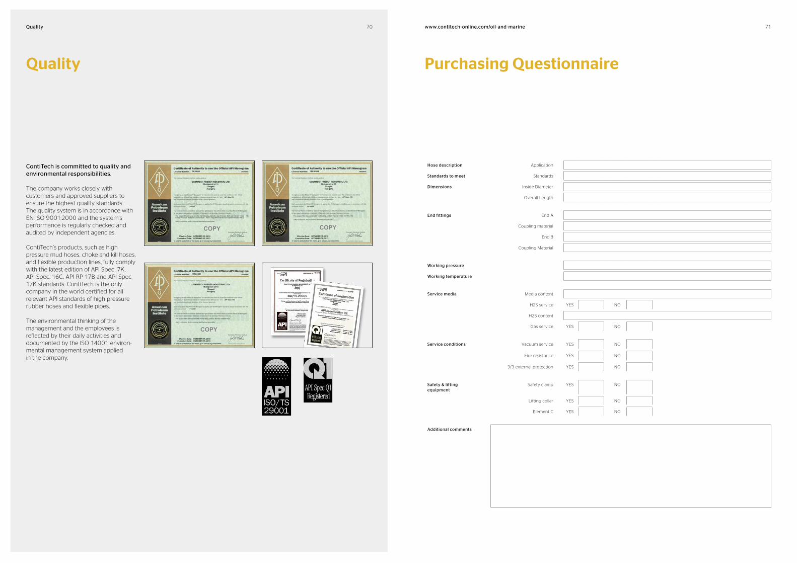
70 71www.contitechonline.com/oilandmarineQuality
Quality Purchasing Questionnaire
ContiTech is committed to quality and environmental responsibilities.
The company works closely with customers and approved suppliers to ensure the highest quality standards. The quality system is in accordance with EN ISO 9001:2000 and the system’s performance is regularly checked and audited by independent agencies.
ContiTech’s products, such as high pressure mud hoses, choke and kill hoses, and flexible production lines, fully comply with the latest edition of API Spec. 7K, API Spec. 16C, API RP 17B and API Spec 17K standards. ContiTech is the only company in the world certified for all relevant API standards of high pressure rubber hoses and flexible pipes.
The environmental thinking of the management and the employees is reflected by their daily activities and documented by the ISO 14001 environ-mental management system applied in the company.
Hose description Application
Standards to meet Standards
Dimensions Inside Diameter
Overall Length
End fittings End A
Coupling material
End B
Coupling Material
Working pressure
Working temperature
Service media Media content
H2S service YES NO
H2S content
Gas service YES NO
Service conditions Vacuum service YES NO
Fire resistance YES NO
3/3 external protection YES NO
Safety & lifting equipment
Safety clamp YES NO
Lifting collar YES NO
Element C YES NO
Additional comments

xxxx
xxxx
xxxx
x P
rin
ted
wit
h C
on
tiTe
ch o
ffse
t p
rin
tin
g b
lan
kets
on
ble
ach
ed
pap
er
fre
e o
f ch
lori
ne
Learn more aboutthe contents of thisbrochure.
www.contitech.de
The ContiTech division of the Continental Corporation is a development partner and original equipment supplier to numerous industries for high-quality fun-ctional parts, components and systems. With its know-how in rubber and plastics technology, ContiTech contributes significantly to industrial progress and mobility that is safe, comfortable and eco-friendly.The content of this publication is not legally binding and is provided as information only. The trademarks displayed in this publication are the property of Continental AG and/or its affiliates. Copyright © 2014 ContiTech AG. All rights reserved. For complete information go to: www.contitech.de/discl_en
Contact
Market segmentFluid Technology ContiTech Fluid Oil & Marine Middle East FZEPO Box 261406 – Jebel Ali Free ZoneDubaiTel: +971 56 138 5618Fax: +971 4 436 2318Email: [email protected]
ContiTech Oil & Marine Corp11535 Brittmore Park DriveHouston, TX 77041Phone: +1 832-327-0141Fax: +1 832 327-0148Email: [email protected] ContiTech Rubber Industrial Kft.6728 Szeged, Budapesti ut 10Phone: +36 62 566 975Fax: +36 62 566 999Email: [email protected]
Dunlop Oil & Marine Ltd.Pyewipe, Moody LaneGrimsby, North East Lincolnshire, DN31 2SYTel: +44 1472 359281Fax: +44 1472 362948Email: [email protected]
Dunlop Oil & Marine Ltd.Jubilee Industrial EstateAshington, Northumberland, NE63 8UBPhone: +44 1670 528700Fax: +44 1670 520 535Email: [email protected]
Dunlop Oil & Marine Ltd.Hareness RoadAltens, Aberdeen, AB12 3LETel: +44 1224 853 810Fax: +44 1224 824 058Email: [email protected]
Eddelbuttel & Schneider GmbHHannoversche Straße 8821079 Hamburg, GermanyTel: +49 (0) 40-767 366-0Fax: +49 (0) 40 767 366 77Email: [email protected]
Your local contactwww.contitech.de/contactlocator