CONTENTS · Seminar Report ‘03 0 CONTENTS • Definition and Overview • Fundamentals of DWDM...
26
Seminar Report ‘03 0 CONTENTS • Definition and Overview • Fundamentals of DWDM Technology • Development of DWDM Technology • WDM with Two Channels • Evolution of DWDM • The Challenges of Today's Telecommunications Network • Resolving the Capacity Crisis • Capacity Expansion and Flexibility • Capacity Expansion Potential • DWDM Incremental Growth • The Optical Layer as the Unifying Layer • Optical Amplifiers • Multiplexers and Demultiplexers • DWDM System Functions • Enabling Technologies • Components and Operation • Transponders • Operation of a Transponder Based DWDM System • Key DWDM System Characteristics • Conclusion
Transcript of CONTENTS · Seminar Report ‘03 0 CONTENTS • Definition and Overview • Fundamentals of DWDM...
Seminar Report ‘03 0
CONTENTS
• Definition and Overview
• Fundamentals of DWDM Technology
• Development of DWDM Technology
• WDM with Two Channels
• Evolution of DWDM
• The Challenges of Today's Telecommunications Network
• Resolving the Capacity Crisis
• Capacity Expansion and Flexibility
• Capacity Expansion Potential
• DWDM Incremental Growth
• The Optical Layer as the Unifying Layer
• Optical Amplifiers
• Multiplexers and Demultiplexers
• DWDM System Functions
• Enabling Technologies
• Components and Operation
• Transponders
• Operation of a Transponder Based DWDM System
• Key DWDM System Characteristics
• Conclusion
Seminar Report ‘03 1
Definition Dense wavelength division multiplexing (DWDM) is a fiber-optic
transmission technique that employs light wavelengths to transmit data
parallel-by-bit or serial-by-character.
Overview The role of scalable DWDM systems in enabling service providers to
accommodate consumer demand for ever-increasing amounts of
bandwidth is important. DWDM is discussed as a crucial component of
optical networks that allows the transmission of e-mail, video,
multimedia, data, and voice—carried in Internet protocol (IP),
asynchronous transfer mode (ATM), and synchronous optical
network/synchronous digital hierarchy (SONET/SDH), respectively,
over the optical layer.
Seminar Report ‘03 2
Fundamentals of DWDM Technology
The emergence of DWDM is one of the most recent and important
phenomena in the development of fiber optic transmission technology.
The functions and components of a DWDM system, including the
enabling technologies, and a description of the operation of a DWDM
system are discussed below.
Seminar Report ‘03 3
Development of DWDM Technology
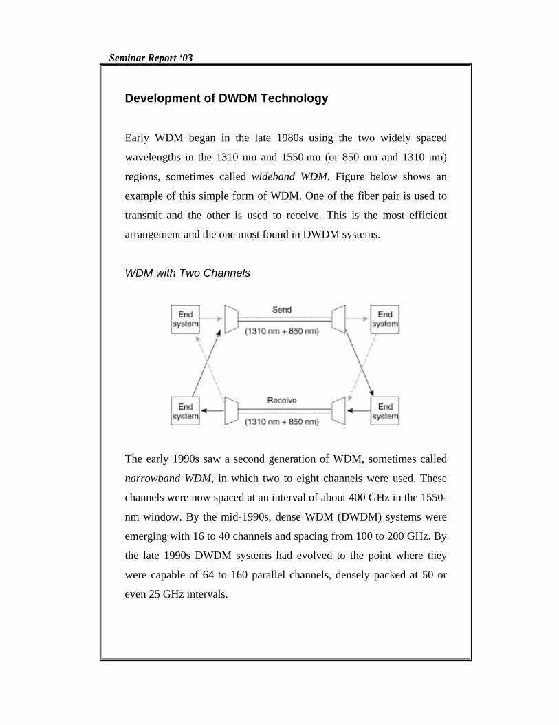
Early WDM began in the late 1980s using the two widely spaced
wavelengths in the 1310 nm and 1550 nm (or 850 nm and 1310 nm)
regions, sometimes called wideband WDM. Figure below shows an
example of this simple form of WDM. One of the fiber pair is used to
transmit and the other is used to receive. This is the most efficient
arrangement and the one most found in DWDM systems.
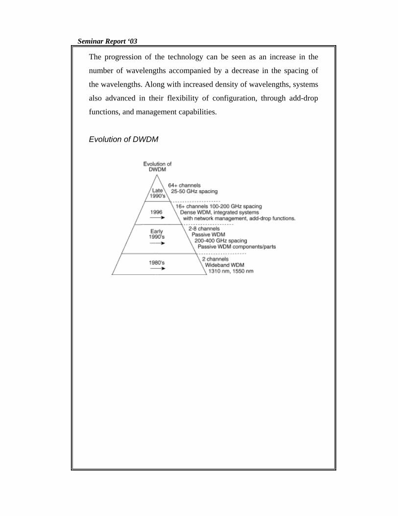
WDM with Two Channels
The early 1990s saw a second generation of WDM, sometimes called
narrowband WDM, in which two to eight channels were used. These
channels were now spaced at an interval of about 400 GHz in the 1550-
nm window. By the mid-1990s, dense WDM (DWDM) systems were
emerging with 16 to 40 channels and spacing from 100 to 200 GHz. By
the late 1990s DWDM systems had evolved to the point where they
were capable of 64 to 160 parallel channels, densely packed at 50 or
even 25 GHz intervals.
Seminar Report ‘03 4
The progression of the technology can be seen as an increase in the
number of wavelengths accompanied by a decrease in the spacing of
the wavelengths. Along with increased density of wavelengths, systems
also advanced in their flexibility of configuration, through add-drop
functions, and management capabilities.
Evolution of DWDM
Seminar Report ‘03 5
The Challenges of Today's Telecommunications Network To understand the importance of DWDM and optical networking, these
capabilities must be discussed in the context of the challenges faced by
the telecommunications industry, and, in particular, service providers.
Forecasts of the amount of bandwidth capacity needed for networks
were calculated on the presumption that a given individual would only
use network bandwidth six minutes of each hour. These formulas did
not factor in the amount of traffic generated by Internet access (300
percent growth per year), faxes, multiple phone lines, modems,
teleconferencing, and data and video transmission. Had these factors
been included, a far different estimate would have emerged. In fact,
today many people use the bandwidth equivalent of 180 minutes or
more each hour. Therefore, an enormous amount of bandwidth capacity
is required to provide the services demanded by consumers. No one
could have predicted the network growth necessary to meet the
demand.
In addition to this explosion in consumer demand for bandwidth, many
service providers are coping with fiber exhaust in their networks. An
industry survey indicated that in 1995, the amount of embedded fiber
already in use in the average network was between 70 percent and 80
percent. Today, many carriers are nearing one hundred–percent
capacity utilization across significant portions of their networks.
Another problem for carriers is the challenge of deploying and
integrating diverse technologies in one physical infrastructure.
Customer demands and competitive pressures mandate that carriers
offer diverse services economically and deploy them over the
embedded network. DWDM provides service providers an answer to
that demand.
Seminar Report ‘03 6
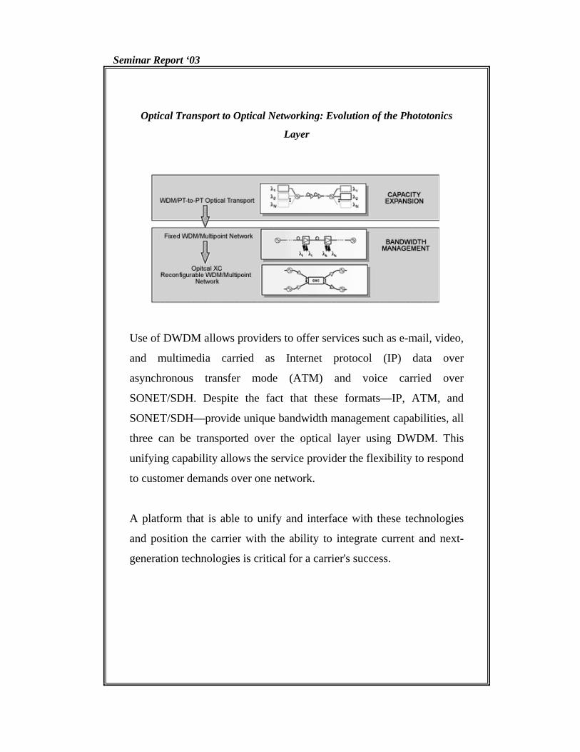
Optical Transport to Optical Networking: Evolution of the Phototonics
Layer
Use of DWDM allows providers to offer services such as e-mail, video,
and multimedia carried as Internet protocol (IP) data over
asynchronous transfer mode (ATM) and voice carried over
SONET/SDH. Despite the fact that these formats—IP, ATM, and
SONET/SDH—provide unique bandwidth management capabilities, all
three can be transported over the optical layer using DWDM. This
unifying capability allows the service provider the flexibility to respond
to customer demands over one network.
A platform that is able to unify and interface with these technologies
and position the carrier with the ability to integrate current and next-
generation technologies is critical for a carrier's success.
Seminar Report ‘03 7
Resolving the Capacity Crisis
Faced with the multifaceted challenges of increased service needs, fiber
exhaust, and layered bandwidth management, service providers need
options to provide an economical solution. One way to alleviate fiber
exhaust is to lay more fiber, and, for those networks where the cost of
laying new fiber is minimal, this will prove the most economical
solution. However, laying new fiber will not necessarily enable the
service provider to provide new services or utilize the bandwidth
management capability of a unifying optical layer.
A second choice is to increase the bit rate using time division
multiplexing (TDM), where TDM increases the capacity of a fiber by
slicing time into smaller intervals so that more bits (data) can be
transmitted per second. Traditionally, this has been the industry method
of choice (DS–1, DS–2, DS–3, etc.). However, when service providers
use this approach exclusively, they must make the leap to the higher bit
rate in one jump, having purchased more capacity than they initially
need. Based on the SONET hierarchy, the next incremental step from
10 Gbps TDM is 40 Gbps—a quantum leap that many believe will not
be possible for TDM technology in the near future. This method has
also been used with transport networks that are based on either the
synchronous optical network (SONET) standard for North America or
the synchronous digital network (SDH) standard for international
networks.
Seminar Report ‘03 8
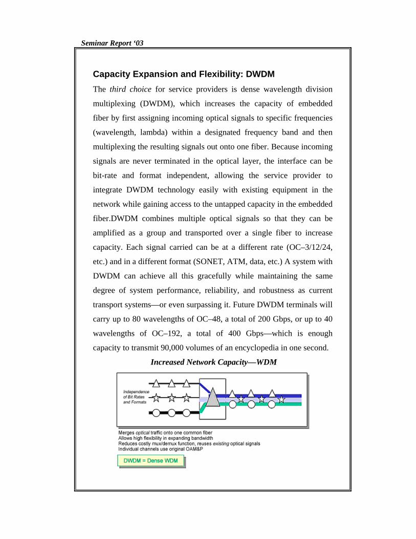
Capacity Expansion and Flexibility: DWDM The third choice for service providers is dense wavelength division
multiplexing (DWDM), which increases the capacity of embedded
fiber by first assigning incoming optical signals to specific frequencies
(wavelength, lambda) within a designated frequency band and then
multiplexing the resulting signals out onto one fiber. Because incoming
signals are never terminated in the optical layer, the interface can be
bit-rate and format independent, allowing the service provider to
integrate DWDM technology easily with existing equipment in the
network while gaining access to the untapped capacity in the embedded
fiber.DWDM combines multiple optical signals so that they can be
amplified as a group and transported over a single fiber to increase
capacity. Each signal carried can be at a different rate (OC–3/12/24,
etc.) and in a different format (SONET, ATM, data, etc.) A system with
DWDM can achieve all this gracefully while maintaining the same
degree of system performance, reliability, and robustness as current
transport systems—or even surpassing it. Future DWDM terminals will
carry up to 80 wavelengths of OC–48, a total of 200 Gbps, or up to 40
wavelengths of OC–192, a total of 400 Gbps—which is enough
capacity to transmit 90,000 volumes of an encyclopedia in one second.
Increased Network Capacity—WDM
Seminar Report ‘03 9
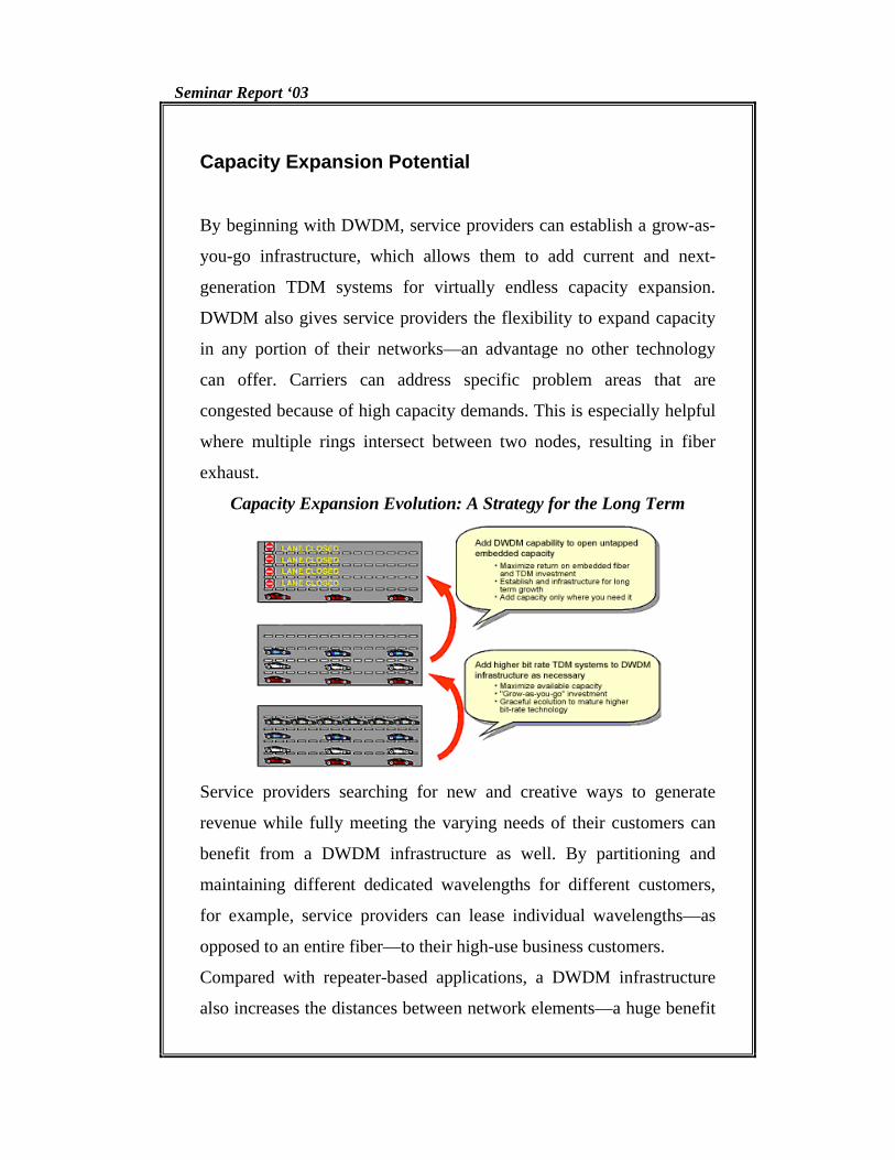
Capacity Expansion Potential
By beginning with DWDM, service providers can establish a grow-as-
you-go infrastructure, which allows them to add current and next-
generation TDM systems for virtually endless capacity expansion.
DWDM also gives service providers the flexibility to expand capacity
in any portion of their networks—an advantage no other technology
can offer. Carriers can address specific problem areas that are
congested because of high capacity demands. This is especially helpful
where multiple rings intersect between two nodes, resulting in fiber
exhaust.
Capacity Expansion Evolution: A Strategy for the Long Term
Service providers searching for new and creative ways to generate
revenue while fully meeting the varying needs of their customers can
benefit from a DWDM infrastructure as well. By partitioning and
maintaining different dedicated wavelengths for different customers,
for example, service providers can lease individual wavelengths—as
opposed to an entire fiber—to their high-use business customers.
Compared with repeater-based applications, a DWDM infrastructure
also increases the distances between network elements—a huge benefit
Seminar Report ‘03 10
for long-distance service providers looking to reduce their initial
network investments significantly. The fiber-optic amplifier component
of the DWDM system enables a service provider to save costs by
taking in and amplifying optical signals without converting them to
electrical signals. Furthermore, DWDM allows service providers to do
it on a broad range of wavelengths in the 1.55µm region. For example,
with a DWDM system multiplexing up to 16 wavelengths on a single
fiber, carriers can decrease the number of amplifiers by a factor of 16 at
each regenerator site. Using fewer regenerators in long-distance
networks results in fewer interruptions and improved efficiency.
Seminar Report ‘03 11
DWDM Incremental Growth
A DWDM infrastructure is designed to provide a graceful network
evolution for service providers who seek to address their customers'
ever-increasing capacity demands. Because a DWDM infrastructure
can deliver the necessary capacity expansion, laying a foundation based
on this technology is viewed as the best place to start. By taking
incremental growth steps with DWDM, it is possible for service
providers to reduce their initial costs significantly while deploying the
network infrastructure that will serve them in the long run.
Some industry analysts have hailed DWDM as a perfect fit for
networks that are trying to meet demands for more bandwidth.
However, these experts have noted the conditions for this fit: a DWDM
system simply must be scalable. Despite the fact that a system of OC–
48 interfacing with 8 or 16 channels per fiber might seem like overkill
now, such measures are necessary for the system to be efficient even
two years from now.
Because OC–48 terminal technology and the related operations support
systems (OSSs) match up with DWDM systems today, it is possible for
service providers to begin evolving the capacity of the TDM systems
already connected to their network. Mature OC–192 systems can be
added later to the established DWDM infrastructure to expand capacity
to 40 Gbps and beyond.
Seminar Report ‘03 12
The Optical Layer as the Unifying Layer
Aside from the enormous capacity gained through optical networking,
the optical layer provides the only means for carriers to integrate the
diverse technologies of their existing networks into one physical
infrastructure. DWDM systems are bit-rate and format independent and
can accept any combination of interface rates (e.g., synchronous,
asynchronous, OC–3, –12, –48, or –192) on the same fiber at the same
time. If a carrier operates both ATM and SONET networks, the ATM
signal does not have to be multiplexed up to the SONET rate to be
carried on the DWDM network. Because the optical layer carries
signals without any additional multiplexing, carriers can quickly
introduce ATM or IP without deploying an overlay network. An
important benefit of optical networking is that it enables any type of
cargo to be carried on the highway.
But DWDM is just the first step on the road to full optical networking
and the realization of the optical layer. The concept of an all-optical
network implies that the service provider will have optical access to
traffic at various nodes in the network, much like the SONET layer for
SONET traffic. Optical wavelength add/drop (OWAD) offers that
capability, where wavelengths are added or dropped to or from a fiber,
without requiring a SONET terminal. But ultimate bandwidth
management flexibility will come with a cross-connect capability on
the optical layer. Combined with OWAD and DWDM, the optical
cross-connect (OXC) will offer service providers the ability to create a
flexible, high-capacity, efficient optical network with full optical
bandwidth management.
Seminar Report ‘03 13
Optical Amplifiers The technology that allows this high-speed, high-volume transmission
is in the optical amplifier. Optical amplifiers operate in a specific band
of the frequency spectrum and are optimized for operation with existing
fiber, making it possible to boost lightwave signals and thereby extend
their reach without converting them back to electrical form.
Demonstrations have been made of ultrawideband optical-fiber
amplifiers that can boost lightwave signals carrying over 100 channels
(or wavelengths) of light.
Due to attenuation, there are limits to how long a fiber segment can
propagate a signal with integrity before it has to be regenerated. Before
the arrival of optical amplifiers (OAs), there had to be a repeater for
every signal transmitted. The OA has made it possible to amplify all
the wavelengths at once and without optical-electrical-optical (OEO)
conversion. Besides being used on optical links, optical amplifiers also
can be used to boost signal power after multiplexing or before
demultiplexing, both of which can introduce loss into the system.
Multiplexers and Demultiplexers Because DWDM systems send signals from several sources over a
single fiber, they must include some means to combine the incoming
signals. This is done with a multiplexer, which takes optical
wavelengths from multiple fibers and converges them into one beam.
At the receiving end the system must be able to separate out the
components of the light so that they can be discreetly detected.
Demultiplexers perform this function by separating the received beam
into its wavelength components and coupling them to individual fibers.
Demultiplexing must be done before the light is detected, because
Seminar Report ‘03 14
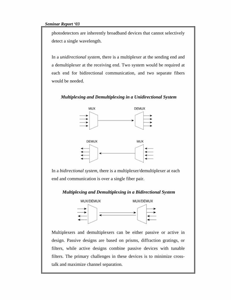
photodetectors are inherently broadband devices that cannot selectively
detect a single wavelength.
In a unidirectional system, there is a multiplexer at the sending end and
a demultiplexer at the receiving end. Two system would be required at
each end for bidirectional communication, and two separate fibers
would be needed.
Multiplexing and Demultiplexing in a Unidirectional System
In a bidirectional system, there is a multiplexer/demultiplexer at each
end and communication is over a single fiber pair.
Multiplexing and Demultiplexing in a Bidirectional System
Multiplexers and demultiplexers can be either passive or active in
design. Passive designs are based on prisms, diffraction gratings, or
filters, while active designs combine passive devices with tunable
filters. The primary challenges in these devices is to minimize cross-
talk and maximize channel separation.
Seminar Report ‘03 15
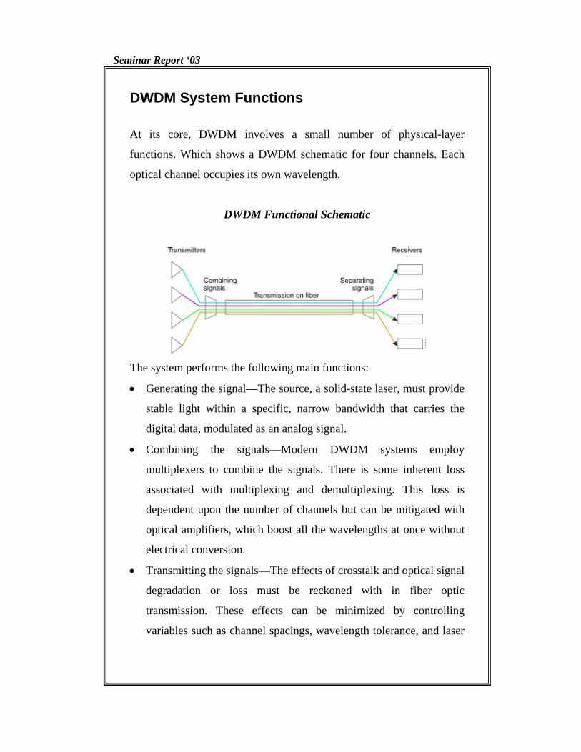
DWDM System Functions At its core, DWDM involves a small number of physical-layer
functions. Which shows a DWDM schematic for four channels. Each
optical channel occupies its own wavelength.
DWDM Functional Schematic
The system performs the following main functions:
• Generating the signal—The source, a solid-state laser, must provide
stable light within a specific, narrow bandwidth that carries the
digital data, modulated as an analog signal.
• Combining the signals—Modern DWDM systems employ
multiplexers to combine the signals. There is some inherent loss
associated with multiplexing and demultiplexing. This loss is
dependent upon the number of channels but can be mitigated with
optical amplifiers, which boost all the wavelengths at once without
electrical conversion.
• Transmitting the signals—The effects of crosstalk and optical signal
degradation or loss must be reckoned with in fiber optic
transmission. These effects can be minimized by controlling
variables such as channel spacings, wavelength tolerance, and laser
Seminar Report ‘03 16
power levels. Over a transmission link, the signal may need to be
optically amplified.
• Separating the received signals—At the receiving end, the
multiplexed signals must be separated out. Although this task would
appear to be simply the opposite of combining the signals, it is
actually more technically difficult.
• Receiving the signals—The demultiplexed signal is received by a
photodetector.
In addition to these functions, a DWDM system must also be equipped
with client-side interfaces to receive the input signal. This function is
performed by transponders. On the DWDM side are interfaces to the
optical fiber that links DWDM systems.
Seminar Report ‘03 17
Enabling Technologies Optical networking, unlike SONET/SDH, does not rely on electrical
data processing. As such, its development is more closely tied to optics
than to electronics. In its early form, WDM was capable of carrying
signals over two widely spaced wavelengths, and for a relatively short
distance. To move beyond this initial state, WDM needed both
improvements in existing technologies and invention of new
technologies. Improvements in optical filters and narrowband lasers
enabled DWDM to combine more than two signal wavelengths on a
fiber. The invention of the flat-gain optical amplifier, coupled in line
with the transmitting fiber to boost the optical signal, dramatically
increased the viability of DWDM systems by greatly extending the
transmission distance.
Other technologies that have been important in the development of
DWDM include improved optical fiber with lower loss and better
optical transmission characteristics, EDFAs, and devices such as fiber
Bragg gratings used in optical add/drop multiplexers.
Seminar Report ‘03 18
Components and Operation
DWDM is a core technology in an optical transport network. The
essential components of DWDM can be classified by their place in the
system as follows:
• On the transmit side, lasers with precise, stable wavelengths
• On the link, optical fiber that exhibits low loss and transmission
performance in the relevant wavelength spectra, in addition to flat-
gain optical amplifiers to boost the signal on longer spans
• On the receive side, photodetectors and optical demultiplexers using
thin film filters or diffractive elements
• Optical add/drop multiplexers and optical cross-connect
components
Seminar Report ‘03 19
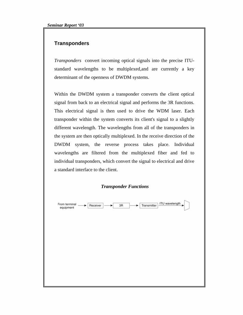
Transponders
Transponders convert incoming optical signals into the precise ITU-
standard wavelengths to be multiplexed,and are currently a key
determinant of the openness of DWDM systems.
Within the DWDM system a transponder converts the client optical
signal from back to an electrical signal and performs the 3R functions.
This electrical signal is then used to drive the WDM laser. Each
transponder within the system converts its client's signal to a slightly
different wavelength. The wavelengths from all of the transponders in
the system are then optically multiplexed. In the receive direction of the
DWDM system, the reverse process takes place. Individual
wavelengths are filtered from the multiplexed fiber and fed to
individual transponders, which convert the signal to electrical and drive
a standard interface to the client.
Transponder Functions
Seminar Report ‘03 20
Operation of a Transponder Based DWDM System End-to-end operation of a unidirectional DWDM system.
Anatomy of a DWDM System
The following steps describe the system shown in Figure above.
1. The transponder accepts input in the form of standard single-mode
or multimode laser. The input can come from different physical
media and different protocols and traffic types.
2. The wavelength of each input signal is mapped to a DWDM
wavelength.
3. DWDM wavelengths from the transponder are multiplexed into a
single optical signal and launched into the fiber. The system might
also include the ability to accept direct optical signals to the
multiplexer; such signals could come, for example, from a satellite
node.
4. A post-amplifier boosts the strength of the optical signal as it leaves
the system (optional).
5. Optical amplifiers are used along the fiber span as needed
(optional).
6. A pre-amplifier boosts the signal before it enters the end system
(optional).

Seminar Report ‘03 21
7. The incoming signal is demultiplexed into individual DWDM
lambdas (or wavelengths).
8. The individual DWDM lambdas are mapped to the required output
type (for example, OC-48 single-mode fiber) and sent out through
the transponder.

Seminar Report ‘03 22

Seminar Report ‘03 23
References
1. Computer Networks-S.Tenanbaum 2. www.iec.org
3. www.itpapers.com

Seminar Report ‘03 24
ACKNOWLEDGEMENT
I thank God Almighty for the successful completion of my seminar.
Sincere feelings of gratitude for Dr.Agnisharman Namboothiri, Head of the
Department, Information Technology. I express my heartfelt gratitude to
Staff-in-charge, Miss. Sangeetha Jose and Mr. Biju, for their valuable advice
and guidance. I would also like to express my gratitude to all other members
of the faculty of Information Technology department for their cooperation.
I would like to thank my dear friends, for their kind-hearted
cooperation and encouragement.
SHAHAN BABU.P
Seminar Report ‘03 25
ABSTRACT
DWDM(Dense wavelength division multiplexing) is a fiber-optic
transmission technique which is an optimal solution to consumer demand
for ever-increasing amounts of bandwidth. DWDM is a crucial component
of optical networks that resolves capacity crisis, provides flexibility to
expand capacity ,enables efficient and cost-effective data transfer and helps
to integrate various technologies into single infrastructure.