Contents 1. Safety 2. Introduction 3. Programming 4 ... manual-E.pdf · VLT Micro Drive FC 51...
84
Contents 1. Safety 3 Safety Instructions 3 Software Version and Approvals 3 General Warning 3 Avoid unintended Start 4 Before Commencing Repair Work 4 2. Introduction 5 Type Code 5 3. Programming 7 How to Programme 7 Programming with MCT-10 Set-up Software 7 Programming with the LCP 11 or LCP 12 7 Status Menu 9 Quick Menu 9 Main Menu 10 4. Parameter Descriptions 11 Parameter group 0: Operation/Display 11 Parameter Group 1: Load/Motor 15 Parameter Group 2: Brakes 22 Parameter Group 3: Reference/Ramps 25 Parameter Group 4: Limits/Warnings 30 Parameter Group 5: Digital In/Out 33 Parameter Group 6: Analogue In/Out 37 Parameter Group 7: Controllers 42 Parameter Group 8: Communication 44 Parameter Group 13: Smart Logic 48 Parameter Group 14: Special Functions 55 Parameter Group 15: Drive Information 57 Parameter Group 16: Data Readouts 59 16-09 Custom Readout 59 5. Parameter Lists 63 Conversion Index 67 Change during operation 67 2-Set-up 67 Type 67 0-** Operation/Display 68 1-** Load/Motor 69 VLT ® Micro Drive FC 51 Contents MG.02.C4.02 - VLT ® is a registered Danfoss trademark 1
Transcript of Contents 1. Safety 2. Introduction 3. Programming 4 ... manual-E.pdf · VLT Micro Drive FC 51...
Contents
1. Safety 3
Safety Instructions 3
Software Version and Approvals 3
General Warning 3
Avoid unintended Start 4
Before Commencing Repair Work 4
2. Introduction 5
Type Code 5
3. Programming 7
How to Programme 7
Programming with MCT-10 Set-up Software 7
Programming with the LCP 11 or LCP 12 7
Status Menu 9
Quick Menu 9
Main Menu 10
4. Parameter Descriptions 11
Parameter group 0: Operation/Display 11
Parameter Group 1: Load/Motor 15
Parameter Group 2: Brakes 22
Parameter Group 3: Reference/Ramps 25
Parameter Group 4: Limits/Warnings 30
Parameter Group 5: Digital In/Out 33
Parameter Group 6: Analogue In/Out 37
Parameter Group 7: Controllers 42
Parameter Group 8: Communication 44
Parameter Group 13: Smart Logic 48
Parameter Group 14: Special Functions 55
Parameter Group 15: Drive Information 57
Parameter Group 16: Data Readouts 59
16-09 Custom Readout 59
5. Parameter Lists 63
Conversion Index 67
Change during operation 67
2-Set-up 67
Type 67
0-** Operation/Display 68
1-** Load/Motor 69
VLT® Micro Drive FC 51 Contents
MG.02.C4.02 - VLT® is a registered Danfoss trademark 1

2-** Brakes 70
3-** Reference/Ramps 71
4-** Limits/Warnings 72
5-** Digital In/Out 73
6-** Analog In/Out 74
7-** Controllers 75
8-** Comm. and Options 76
13-** Smart Logic 77
14-** Special Functions 78
15-** Drive Information 79
16-** Data Readouts 80
6. Troubleshooting 81
Alarm, Warning and Extended Status Word 82
Index 83
Contents VLT® Micro Drive FC 51
2 MG.02.C4.02 - VLT® is a registered Danfoss trademark

1. Safety
1.1.1. High Voltage Warning
The voltage of the frequency converter is dangerous whenever it is connected to mains. Incorrect installation of the motor or frequency
converter may cause damage to the equipment, serious injury or death. Consequently, it is essential to comply with the instructions
in this manual as well as local and national rules and safety regulations.
1.1.2. Safety Instructions
• Make sure the frequency converter is properly connected to earth.
• Do not remove mains connections, motor connections or other power connections while the frequency converter is connected to power.
• Protect users against supply voltage.
• Protect the motor against overloading according to national and local regulations.
• The earth leakage current exceeds 3.5 mA.
• The [OFF] key is not a safety switch. It does not disconnect the frequency converter from mains.
1.1.3. Software Version and Approvals
Software VersionProgramming Guide
VLT Micro DriveFC 51 Series
This Programming Guide can be used for all VLT Micro Drive frequency drives with software version
2.1x.The software version number can be read in
parameter 15-43.
1.1.4. General Warning
Warning:
Touching the electrical parts may be fatal - even after the equipment has been disconnected from mains.
Also make sure that other voltage inputs have been disconnected (linkage of DC intermediate circuit).
Be aware that there may be high voltage on the DC link even when the LEDs are turned off.
Before touching any potentially live parts of the frequency converter, wait at least 4 minutes for all sizes.
Shorter time is allowed only if indicated on the nameplate for the specific unit.
VLT® Micro Drive FC 51 1. Safety
MG.02.C4.02 - VLT® is a registered Danfoss trademark 3
1

Leakage Current
The earth leakage current from the frequency converter exceeds 3.5 mA. According to IEC 61800-5-1 a reinforced Protective Earth
connection must be ensured by means of a min. 10mm² Cu or an addtional PE wire - with the same cable cross section as the Mains
wiring - must be terminated separately.
Residual Current Device
This product can cause a DC current in the protective conductor. Where a residual current device (RCD) is used for extra protection,
only an RCD of Type B (time delayed) shall be used on the supply side of this product. See also Danfoss Application Note on RCD, MN.
90.GX.YY.
Protective earthing of the frequency converter and the use of RCDs must always follow national and local regulations.
Motor overload protection is possible by setting Parameter 1-90 Motor thermal protection to the value ETR trip. For the North American
market: ETR functions provide class 20 motor overload protection, in accordance with NEC.
Installation in high altitudes:
For altitudes above 2 km, please contact Danfoss regarding PELV.
1.1.5. IT Mains
IT Mains
Installation on isolated mains source, i.e. IT mains.
Max. supply voltage allowed when connected to mains: 440 V.
As an option, Danfoss offers line filters for improved harmonics performance.
1.1.6. Avoid unintended Start
While the frequency converter is connected to mains, the motor can be started/stopped using digital commands, bus commands, references or via the
Local Control Panel.
• Disconnect the frequency converter from mains whenever personal safety considerations make it necessary to avoid unintended start of any
motors.
• To avoid unintended start, always activate the [OFF] key before changing parameters.
1.1.7. Disposal Instruction
Equipment containing electrical components must not be disposed of together with domestic waste.
It must be separately collected with electrical and electronic waste according to local and currently valid leg-
islation.
1.1.8. Before Commencing Repair Work
1. Disconnect FC 51 from mains (and external DC supply, if present.)
2. Wait for 4 minutes for discharge of the DC-link.
3. Disconnect DC bus terminals and brake terminals (if present)
4. Remove motor cable
1. Safety VLT® Micro Drive FC 51
4 MG.02.C4.02 - VLT® is a registered Danfoss trademark
1

2. Introduction
2.1.1. FC Identification
Below is an example of the frequency converter nameplate sticker. This sticker is located on the top of each frequency converter and shows the ratings,
serial number, warnings catalog number, and other relevant data for each unit. See following tables for details, how to read the Type code string.
Illustration 2.1: This example shows the identification sticker.
2.1.2. Type Code
Description Pos Possible choiceProduct group 1-3 Adjustable Frequency ConvertersSeries and product type 4-6 Micro DrivePower size 7-10 0.18 - 7.5 kWMains voltage 11-12 S2: Single phase 200 - 240 V AC
T 2: Three phase 200 - 240 V ACT 4: Three phase 380 - 480 V AC
Enclosure 13-15 IP20/ChassisRFI filter 16-17 HX: No RFI filter
H1: RFI filter class A1/BH3:RFI filter A1/B (reduced cable length)
Brake 18 B: Brake chopper includedX: No brake chopper included
Display 19 X: No Local Control PanelN: Numerical Local Control Panel (LCP)P: Numerical Local Control Panel (LCP) with potentiometer
Coating PCB 20 C: Coated PCBX. No coated PCB
Mains option 21 X: No mains optionAdaptation A 22 X: No adaptationAdaptation B 23 X: No adaptationSoftware release 24-27 SXXX: Latest release - std. software
Table 2.1: Type code description
VLT® Micro Drive FC 51 2. Introduction
MG.02.C4.02 - VLT® is a registered Danfoss trademark 5
2

2.1.3. Symbols
Symbols used in this Programming Guide.
NB!
Indicates something to be noted by the reader.
Indicates a general warning.
Indicates a high-voltage warning.
* Indicates default setting
2.1.4. Abbreviations and Standards
Abbreviations: Terms: SI-units: I-P units: Acceleration m/s2 ft/s2
AWG American wire gauge Auto Tune Automatic Motor Tuning °C Celsius Current A AmpILIM Current limit Energy J = N·m ft-lb, Btu°F Fahrenheit FC Frequency Converter Frequency Hz HzkHz Kilohertz LCP Local Control Panel mA Milliampere ms Millisecond min Minute MCT Motion Control Tool M-TYPE Motor Type Dependent Nm Newton Metres in-lbsIM,N Nominal motor current fM,N Nominal motor frequency PM,N Nominal motor power UM,N Nominal motor voltage par. Parameter PELV Protective Extra Low Voltage Power W Btu/hr, hp Pressure Pa = N/m² psi, psf, ft of waterIINV Rated Inverter Output Current RPM Revolutions Per Minute SR Size Related Temperature ˚C ˚F Time s s,hrTLIM Torque limit Voltage V V
Table 2.2: Abbreviation and Standards table .
2. Introduction VLT® Micro Drive FC 51
6 MG.02.C4.02 - VLT® is a registered Danfoss trademark
2
3. Programming
3.1. How to Programme
3.1.1. Programming with MCT-10 Set-up Software
The frequency converter can be programmed from a PC via RS485 com-port by installing the MCT-10 Set-up Software.
This software can either be ordered using code number 130B1000 or downloaded from the Danfoss Web site: www.danfoss.com, Business Area: Motion
Controls.
Please refer to manual MG.10.RX.YY.
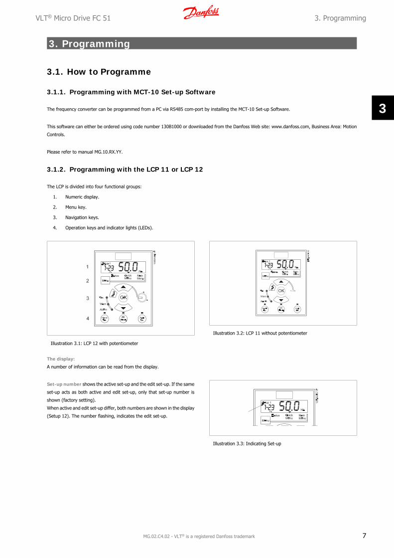
3.1.2. Programming with the LCP 11 or LCP 12
The LCP is divided into four functional groups:
1. Numeric display.
2. Menu key.
3. Navigation keys.
4. Operation keys and indicator lights (LEDs).
Illustration 3.1: LCP 12 with potentiometer
Illustration 3.2: LCP 11 without potentiometer
The display:
A number of information can be read from the display.
Set-up number shows the active set-up and the edit set-up. If the same
set-up acts as both active and edit set-up, only that set-up number is
shown (factory setting).
When active and edit set-up differ, both numbers are shown in the display
(Setup 12). The number flashing, indicates the edit set-up.
Illustration 3.3: Indicating Set-up
VLT® Micro Drive FC 51 3. Programming
MG.02.C4.02 - VLT® is a registered Danfoss trademark 7
3

The small digits to the left are the selected parameter number.
Illustration 3.4: Indicating selected par. no.
The large digits in the middle of the display show the value of the se-
lected parameter.
Illustration 3.5: Indicating value of selected par.
The right side of the display shows the unit of the selected parameter.
This can be either Hz, A, V, kW, HP, %, s or RPM.
Illustration 3.6: Indicating unit of selected par.
Motor direction is shown to the bottom left of the display - indicated
by a small arrow pointing either clockwise or counterclockwise.
Illustration 3.7: Indicating motor direction
Use the [MENU] key to select one of the following menus:
Status Menu:
The Status Menu is either in Readout Mode or Hand on Mode. In Readout Mode the value of the currently selected readout parameter is shown in the
display.
In Hand on Mode the local LCP reference is displayed.
Quick Menu:
Displays Quick Menu parameters and their settings. Parameters in the Quick Menu can be accessed and edited from here. Most applications can be run
by setting the parameters in the Quick Menus.
Main Menu:
Displays Main Menu parameters and their settings. All parameters can be accessed and edited here. A parameter overview is found later in this manual.
Indicator lights:
• Green LED: The frequency converter is on.
• Yellow LED: Indicates a warning. Please see section Troubleshooting
• Flashing red LED: Indicates an alarm. Please see section Troubleshooting
3. Programming VLT® Micro Drive FC 51
8 MG.02.C4.02 - VLT® is a registered Danfoss trademark
3

Navigation Keys:
[Back]: For moving to the previous step or layer in the navigation structure.
Arrows [] []: For maneuvering between parameter groups, parameters and within parameters.
[OK]: For selecting a parameter and for accepting changes to parameter settings.
Operation Keys:
A yellow light above the operation keys indicates the active key.
[Hand on]: Starts the motor and enables control of the frequency converter via the LCP.
[Off/Reset]: The motor stops except in alarm mode. In that case the motor will be reset.
[Auto on]: The frequency converter is controlled either via control terminals or serial communication.
[Potentiometer] (LCP12): The potentiometer works in two ways depending on the mode in which the frequency converter is running.
In Auto Mode the potentiometer acts as an extra programmable analog input.
In Hand on Mode the potentiometer controls local reference.
3.2. Status Menu
After power up the Status Menu is active. Use the [MENU] key to toggle
between Status, Quick Menu and Main Menu.
Arrows [] and [] toggles between the choices in each menu.
The display indicates the status mode with a small arrow above “Status”.
Illustration 3.8: Indicating Status mode
3.3. Quick Menu
The Quick Menu gives easy access to the most frequently used parameters.
1. To enter the Quick Menu, press [MENU] key until indicator in display is placed above Quick Menu.
2. Use [] [] to select either QM1 or QM2, then press [OK].
3. Use [] [] to browse through the parameters in the Quick Menu.
4. Press [OK] to select a parameter.
5. Use [] [] to change the value of a parameter setting.
6. Press [OK] to accept the change.
7. To exit, press either [Back] twice to enter Status, or press [Menu] once to enter Main Menu.
Illustration 3.9: Indicating Quick Menu mode
VLT® Micro Drive FC 51 3. Programming
MG.02.C4.02 - VLT® is a registered Danfoss trademark 9
3
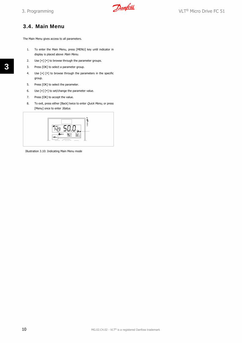
3.4. Main Menu
The Main Menu gives access to all parameters.
1. To enter the Main Menu, press [MENU] key until indicator in
display is placed above Main Menu.
2. Use [] [] to browse through the parameter groups.
3. Press [OK] to select a parameter group.
4. Use [] [] to browse through the parameters in the specific
group.
5. Press [OK] to select the parameter.
6. Use [] [] to set/change the parameter value.
7. Press [OK] to accept the value.
8. To exit, press either [Back] twice to enter Quick Menu, or press
[Menu] once to enter Status.
Illustration 3.10: Indicating Main Menu mode
3. Programming VLT® Micro Drive FC 51
10 MG.02.C4.02 - VLT® is a registered Danfoss trademark
3

4. Parameter Descriptions
4.1. Parameter group 0: Operation/Display
0-03 Regional Settings
Option: Function:In order to meet the needs for different default settings in different parts of the world, par. 0-03, Regional
Settings, is implemented in the frequency converter. The selected setting influences the default setting of the
motor nominal frequency.
[0 ] * International Sets default of par. 1-23, Motor Frequency, to 50 Hz, shows par. 1-20 in kW.
[1] US Sets default of par. 1-23, Motor Frequency, to 60 Hz, shows par. 1-20 in HP.
NB!
This parameter cannot be adjusted while motor runs.
0-04 Operating State at Power-up (Hand Mode)
Option: Function:This parameter controls whether or not the frequency converter should start running the motor when powering
up after a power down in Hand mode.
NB!
If LCP with potentiometer is mounted, reference is set according to actual potentiometer
value.
[0] Resume Frequency converter starts in same Hand or Off State as when powered off.
Local reference is stored and used after power-up.
[1] * Forced Stop, Ref=Old Frequency converter powers up in Off State meaning that motor is stopped after power up.
Local reference is stored and used after power-up.
[2] Forced Stop, Ref=0 Frequency converter powers up in Off State meaning that motor is stopped after power up.
Local reference is set to 0. Thus motor will not start running before local reference has been increased.
4.1.1. 0-1* Set-up Handling
User defined parameters and miscellaneous external inputs (eg. bus, LCP, analog/digital inputs, feedback, etc.) controls the functionality of the frequency
converter.
A complete set of all parameters controlling the frequency converter is called a set-up. The frequency converter contains 2 set-ups, Set-up1 and Set-up
2.
Furthermore, a fixed set of factory settings can be copied into one or more set-ups.
Some of the advantages of having more than one set-up in the frequency converter are
• Run motor in one set-up (Active Set-up) while updating parameters in another set-up (Edit Set-up)
• Connect various motors (one at a time) to frequency converter. Motor data for various motors can be placed in different set-ups.
• Rapidly change settings of frequency converter and/or motor while motor is running (eg. ramp time or preset references) via bus or digital
inputs.
The Active Set-up can be set as Multi Set-up where the active set-up is selected via input on a digital input terminal and/or via the bus control word.
VLT® Micro Drive FC 51 4. Parameter Descriptions
MG.02.C4.02 - VLT® is a registered Danfoss trademark 11
4

NB!
Factory Set-up cannot be used as Active Set-up.
0-10 Active Set-up
Option: Function:Active Set-up controls the motor.
Shifts between set-ups can only happen when
• the motor is coasted
OR
• the set-ups between which the shift happens are linked to each other (see par. 0-12, Linked Set-
ups).
If changing between set-ups that are not linked, the change will not happen before motor is coasted.
NB!
The motor is only considered stopped when it is coasted.
[1 ] * Set-up 1 Set-up 1 is active.
[2] Set-up 2 Set-up 2 is active.
[9] Multi Set-up Select the active set-up via digital input and/or bus, see par. 5-1* choice [23].
0-11 Edit Set-up
Option: Function:The Edit Set-up is for updating parameters in the frequency converter from either LCP or bus. It can be identical
or different from the Active Set-up.
All set-ups can be edited during operation, independently of the active set-up.
[1 ] * Set-up 1 Update parameters in Set-up 1.
[2] Set-up 2 Update parameters in Set-up 2.
[9] Active Set-up Update parameters in set-up selected as Active Set-up (see par. 0-10).
0-12 Link Set-ups
Option: Function:The link ensures synchronizing of the “not changeable during operation” parameter values enabling shift from
one set-up to another during operation.
If the set-ups are not linked, a change between them is not possible while the motor is running. Thus the set-
up change does not occur until the motor is coasted.
[0] Not linked Leaves parameters unchanged in both set-ups and cannot be changed while motor runs.
[1 ] * Linked Copy parameters “not changeable during operation” parameter values into presently selected Edit Set-up.
NB!
This parameter cannot be changed while motor runs.
4.1.2. 0-31 Custom Readout Min Scale
0-31 Custom Readout Min Scale
Range: Function:
0.00 * [0.00 – 9999.00 ] It is possible to create a customized readout related to the output frequency of the unit. The value entered in
par. 0-31 will be shown at 0 Hz. The readout can be shown in the LCP display when in Status Mode or it can be
read in par. 16-09
4. Parameter Descriptions VLT® Micro Drive FC 51
12 MG.02.C4.02 - VLT® is a registered Danfoss trademark
4

4.1.3. 0-32 Custom Readout Max Scale
0-32 Custom Readout Max Scale
Range: Function:
100.0* [0.00 – 9999.00] It is possible to create a customized readout related to the output frequency of the unit. The value entered in
par. 0-32 will be shown at the frequency programmed in par. 4-14 Motor Speed High Limit. The readout can be
shown in the LCP display when in Status Mode or it can be read in par. 16-09
4.1.4. 0-4* LCP Keypad
The frequency converter can operate in the following three modes: Hand, Off and Auto.
Hand: The frequency converter is locally operated and does not allow any remote control. By activating Hand a start signal is given.
OFF: The frequency converter stops with a normal stop ramp. When Off is chosen the frequency converter can only be started by pressing either Hand
or Auto on the LCP.
Auto: In Auto-mode the frequency converter can be remote controlled (bus/digital).
0-40 [Hand on] Key on LCP
Option: Function:[0] Disabled Hand-on key has no function.
[1 ] * Enabled Hand-on key is functional.
0-41 [Off/Reset] Key on LCP
Option: Function:[0] Disable Off/Reset Off/reset key has no function.
[1 ] * Enable Off/Reset Stop signal and reset of any faults.
[2] Enable Reset Only Reset only. Stop (Off) function is disabled.
0-42 [Auto on] Key on LCP
Option: Function:[0] Disabled Auto-on key has no function.
[1 ] * Enabled Auto-on key is functional.
4.1.5. 0-5* Copy/Save
0-50 LCP Copy
Option: Function:The detachable LCP of the frequency converter can be used for storing setups, and thus for transferring data
when moving parameter settings from one frequency converter to another.
NB!
LCP Copy can only be activated from the LCP and ONLY when the motor is coasted.
[1] All to LCP Copy all setups from the frequency converter into the LCP.
[2] All from LCP Copy all setups from LCP to frequency converter.
[3] Size indep. from LCP Copy non motor size dependent data from LCP to frequency converter
0-51 Set-up Copy
Option: Function:Use this function to copy a set-up content into the Edit Set-up.
In order to be able to make a set-up copy ensure that
• the motor is coasted
• par. 0-10, Active Set-up, is set to either Set-up 1 [1] or Set-up 2 [2]
VLT® Micro Drive FC 51 4. Parameter Descriptions
MG.02.C4.02 - VLT® is a registered Danfoss trademark 13
4

NB!
The keyboard/parameter database are blocked while Set-up Copy is running.
[0 ] * No Copy Copy function is inactive
[1] Copy from Set-up 1 Copy from Set-up 1 to edit set-up chosen in par. 0-11, Edit Set-up.
[2] Copy from Set-up 2 Copy from Set-up 2 to edit set-up chosen in par. 0-11, Edit Set-up.
[9] Copy from Factory Set-
up
Copy from Factory Settings to edit set-up chosen in par. 0-11, Edit set-up.
4.1.6. 0-6* Password
0-60 (Main) Menu Password
Range: Function:Use password for protection against unintended change of sensitive parameters, eg. motor parameters.
Password protected parameters can always be read, but cannot be edited without entering the password.
0 * [0 - 999] Enter the password for access to Main Menu via the [Main Menu] key. Select the number that should allow for
changing other parameter values. 0 means there is no password.
NB!
A password only has affect on the LCP - not on the bus communication.
NB!
Pressing buttons [MENU], [OK] and down will unlock the password. This will automatically enter the parameter editing screen in Quick
Menu or Main Menu.
4. Parameter Descriptions VLT® Micro Drive FC 51
14 MG.02.C4.02 - VLT® is a registered Danfoss trademark
4

4.2. Parameter Group 1: Load/Motor
1-00 Configuration Mode
Option: Function:Use this parameter for selecting the application control principle to be used when a Remote Reference is active.
NB!
Changing this parameter will reset parameters 3-00, 3-02 and 3-03 to their default values.
NB!
This parameter cannot be adjusted while motor runs.
[0 ] * Speed Open Loop For normal speed control (References).
[3] Process Closed Loop Enables process closed loop control. See par. group 7-3* for further information on PI-controller.
When running in process closed loop, par. 4-10 Motor Speed Direction must be set to Clockwise [0]
1-01 Motor Control Principle
Option: Function:[0] U/f Is used for parallel connected motors and/or special motor applications. The U/f settings are set in parameters
1-55 and 1-56.
NB!
When running U/f control slip- and load compensations are not included.
[1] * VVC+ Normal running mode, including slip- and load compensations.
1-03 Torque Characteristics
Option: Function:With more torque characteristics it is possible to run low energy consuming, as well as high torque applications.
[0 ] * Constant Torque Motor shaft output provides constant torque under variable speed control.
[2] Automatic Energy Op-
tim.
This function automatically optimizes energy consumption in centrifugal pump and fan applications. See par.
14-41 AEO Minimum Magnetisation.
1-05 Hand Mode Configuration
Option: Function:This parameter is only relevant when parameter 1-00 Configuration Mode is set to Process Closed Loop [3]. The
parameter is used for determining the reference or setpoint handling when changing from Auto Mode to Hand
Mode on the LCP.
[0] Speed Open Loop In Hand Mode the drive always runs in Open Loop configuration regardless of setting in par. 1-00 Configuration
Mode. Local potentiometer (if present) or Arrow up/down determines output frequency limited by Motor Speed
High/Low Limit (parameters 4-14 and 4-12).
[2] * As configuration in par.
1-00
If par. 1-00 Configuration Mode is set to Open Loop [1] function is as described above.
If par. 1-00 is set to Process Closed Loop [3] changing from Auto mode to Hand mode results in a setpoint
change via local potentiometer or Arrow up/down. The change is limited by Reference Max/Min (parameters
3-02 and 3-03).
4.2.1. 1-2* Motor Data
Enter the correct motor nameplate data (power, voltage, frequency, current and speed).
Run AMT, see par. 1-29.
Factory settings for advanced motor data, par. 1-3*, are automatically calculated.
VLT® Micro Drive FC 51 4. Parameter Descriptions
MG.02.C4.02 - VLT® is a registered Danfoss trademark 15
4

NB!
Parameters in parameter group 1.2* cannot be adjusted while motor runs.
1-20 Motor Power [kW]/[HP] (Pm.n)
Option: Function:Enter motor power from nameplate data.
Two sizes down, one size up from nominal VLT rating.
[1] 0.09 kW/0.12 HP
[2] 0.12 kW/0.16 HP
[3] 0.18kW/0.25 HP
[4] 0.25 kW/0.33 HP
[5] 0.37kW/0.50 HP
[6] 0.55 kW/0.75 HP
[7] 0.75 kW/1.00 HP
[8] 1.10 kW/1.50 HP
[9] 1.50 kW/2.00 HP
[10] 2.20 kW/3.00 HP
[11] 3.00 kW/4.00 HP
[12] 3.70 kW/5.00 HP
[13] 4.00 kW/5.40 HP
[14] 5.50 kW/7.50 HP
[15] 7.50 kW/10.0 HP
[16] 11.00 kW/15.00 HP
NB!
Changing this parameter affects par. 1-22 to 1-25,
1-30, 1-33 and 1-35.
1-22 Motor Voltage (U m.n)
Range: Function:230/400 V [50 - 999 V] Enter motor voltage from nameplate data.
1-23 Motor Frequency (f m.n)
Range: Function:
50 Hz* [20-400 Hz] Enter motor frequency from nameplate data.
1-24 Motor Current (I m.n)
Range: Function:
M-type dependent* [0.01 - 26.00 A] Enter motor current from nameplate data.
1-25 Motor Nominal Speed (n m.n)
Range: Function:
M-type Dependent* [100 - 9999
RPM]
Enter motor nominal speed from nameplate data.
1-29 Automatic Motor Tuning (AMT)
Option: Function:Use AMT to optimize motor performance.
4. Parameter Descriptions VLT® Micro Drive FC 51
16 MG.02.C4.02 - VLT® is a registered Danfoss trademark
4

NB!
This parameter cannot be changed while motor runs.
1. Stop the frequency converter – make sure motor is at standstill
2. Choose [2] Enable AMT
3. Apply start signal
– Via LCP: Press Hand On
- Or in Remote On mode: Apply start signal on terminal 18
[0] * Off AMT function is disabled.
[2] Enable AMT AMT function starts running.
NB!
To gain optimum tuning of frequency converter, run AMT on a cold motor.
4.2.2. 1-3* Adv. Motor Data
Adjust advanced motor data using one of these methods:
1. Run AMT on cold motor. Frequency converter measures value from motor.
2. Enter X1 value manually. Obtain value from motor supplier.
3. Use Rs, X1, and X2default setting. Frequency converter establishes setting based on motor nameplate data.
NB!
These parameters cannot be changed while motor runs.
1-30 Stator Resistance (Rs)
Range: Function:
Depending on motor data* [Ohm] Set stator resistance value.
1-33 Stator Leakage Reactance (X1)
Range: Function:
Depending on motor data* [Ohm] Set stator leakage reactance of motor.
1-35 Main Reactance (X2)
Range: Function:
Depending on motor data* [Ohm] Set motor main reactance.
VLT® Micro Drive FC 51 4. Parameter Descriptions
MG.02.C4.02 - VLT® is a registered Danfoss trademark 17
4

4.2.3. 1-5* Load Independent Setting
This parameter group is for setting the load independent motor settings.
1-50 Motor Magnetization at Zero Speed
Range: Function:This parameter enables different thermal load on motor when running at low speed.
100 %* [ 0 - 300%] Enter a percentage of rated magnetizing current. If setting is too low, motor shaft torque may be reduced.
1-52 Min. Speed Normal Magnetizing [Hz]
Range: Function:Use this parameter along with par. 1-50, Motor Magnetizing at Zero Speed.
0.0 Hz* [0.0 - 10.0 Hz] Set frequency required for normal magnetizing current. If frequency is set lower than motor slip frequency, par.
1-50, Motor Magnetizing at Zero Speed is inactive.
1-55 U/f Characteristic - U
Range: Function:This parameter is an array parameter [0-5] and is only functional when par. 1-01, Motor Control Principle is set
to U/f [0].
0.0 V* [0.0 - 999.9 V] Enter voltage at each frequency point to manually form a U/f characteristic matching motor. Frequency points
are defined in par. 1-56, U/f characteristics - F.
1-56 U/f Characteristic - F
Range: Function:This parameter is an array parameter [0-5] and is only functional when par. 1-01, Motor Control Principle is set
to U/f [0].
0.0 Hz* [0.0 - 1000.0 Hz] Enter frequency points to manually form a U/f characteristic matching motor. Voltage at each point is defined
in par. 1-55, U/f Characteristic - U.
Make a U/f characteristic based on 6 definable voltages and frequencies, see below figure.
Simplify U/f characteristics by merging 2 or more points (voltages and frequencies), respectively, are set equal.
Illustration 4.1: Fig. 1 U/f characteristics
4. Parameter Descriptions VLT® Micro Drive FC 51
18 MG.02.C4.02 - VLT® is a registered Danfoss trademark
4

NB!
For par. 1-56 the following applies
[0] ≦ [1] ≦ [2] ≦ [3] ≦ [4] ≦ [5]
4.2.4. 1-6* Load Dependent setting
Parameters for adjusting the load dependent motor settings.
1-60 Low Speed Load Compensation
Range: Function:Use this parameter to gain optimum U/f characteristic when running at low speed.
100 %* [0-199 %] Enter percentage in relation to load when motor runs at low speed.
Change-over point is automatically calculated based on motor size.
1-61 High Speed Load Compensation
Range: Function:Use this parameter to obtain optimum load compensation when running at high speed.
100 %* [0 - 199 %] Enter percentage to compensate in relation to load when motor runs at high speed.
Change-over point is automatically calculated based on motor size.
1-62 Slip Compensation
Range: Function:
100 %* [-400 - 399 %] Compensation for load dependent motor slip.
Slip compensation is calculated automatically based on rated motor speed, nM,N.
NB!
This function is only active when par. 1-00, Configuration Mode, is set to Speed Open Loop
[0], and when par. 1-01, Motor Control Principle, is set to VVC+ [1].
1-63 Slip Compensation Time
Range: Function:0.10 s [0.05 - 5.00 s] Enter slip compensation reaction speed. A high value results in slow reaction whereas a low value results in quick
reaction.
If low-frequency resonance problems arise, use longer time setting.
VLT® Micro Drive FC 51 4. Parameter Descriptions
MG.02.C4.02 - VLT® is a registered Danfoss trademark 19
4

4.2.5. 1-7* Start Adjustments
Considering the need for various start functions in different applications, it is possible to select a number of functions in this parameter group.
1-71 Start Delay
Range: Function:The start delay defines the time to pass from a start command is given until the motor starts accelerating.
Setting start delay to 0.0 sec. disables Start Function, [1-72], when start command is given.
0.0 s* [0.0 - 10.0 s] Enter the time delay required before commencing acceleration.
Par. 1-72 Start Function is active during Start delay time .
1-72 Start Function
Option: Function:[0] DC Hold/Delay Time Motor is energized with DC holding current (par. 2-00) during start delay time.
[1] DC Brake/Delay Time Motor is energized with DC braking current (par. 2-01) during start delay time.
[2] * Coast/Delay Time Inverter is coasted during start delay time (inverter off).
1-73 Flying Start
Option: Function:The Flying Start parameter is used to catch a spinning motor after eg. mains drop-out.
This function is not suitable for hoisting applications.
[0] * Disabled Flying start is not required.
[1] Enabled Frequency converter enabled to catch spinning motor.
NB!
When flying start is enabled par. 1-71, Start Delay, and par. 1-72, Start Function, have no
function.
4.2.6. 1-8* Stop Adjustments
To meet the need for various stop functions in different application these parameters offer some special stop features for the motor.
1-80 Function at Stop
Option: Function:The selected function at stop is active in following situations:
• Stop command is given and output speed is ramped down to Min. Speed for Activating Functions at
Stop.
• Start command is removed (standby), and output speed is ramped down to Min. Speed for Activating
Functions at Stop.
• DC-brake command is given, and DC-brake time has passed
• While running and calculated output speed is below Min. Speed for Activating Functions at Stop.
[0] * Coast The inverter is coasted.
[1] DC hold The motor is energized with a DC current. See par. 2-00 DC Hold Current for more information.
1-82 Min. Speed For Function at Stop [Hz]
Range: Function:
0.0 Hz* [0.0 - 20.0 Hz] Set the speed at which to activate par. 1-80 Function at Stop.
4. Parameter Descriptions VLT® Micro Drive FC 51
20 MG.02.C4.02 - VLT® is a registered Danfoss trademark
4

4.2.7. 1-9* Motor Temperature
With an estimated motor temperature monitor the frequency converter is able to estimate motor temperature without having a thermistor mounted. It
is thus possible to receive a warning or an alarm, if motor temperature exceeds upper operational limit.
1-90 Motor Thermal Protection
Option: Function:Using ETR (Electronic Terminal Relay) the motor temperature is calculated based on frequency, speed and time.
Danfoss recommends using The ETR function, if a thermistor is not present.
NB!
ETR calculation is based on motor data from group 1-2*.
[0] * No Protection Disables temperature monitoring.
[1] Thermistor Warning A thermistor connected to either digital or analog input gives a warning if upper limit of motor temperature
range is exceeded, (see par. 1-93, Thermistor Resource).
[2] Thermistor Trip A thermistor connected to either digital or analog input gives an alarm and makes the frequency converter trip
if upper limit of motor temperature range is exceeded, (see par. 1-93, Thermistor Resource.
[3] ETR Warning If calculated upper limit of motor temperature range is exceeded, a warning occurs.
[4] ETR Trip If 90% of calculated upper limit of motor temperature range is exceeded, an alarm occurs and frequency con-
verter trips.
NB!
When the ETR function has been selected the drive will store the recorded temperature at power down and this temperature will resume
at power up regardless of the elapsed time. Changing par. 1-90 back to [0] No Protection will reset the recorded temperature.
1-93 Thermistor Resource
Option: Function:Select the thermistor input terminal.
[0] * None No thermistor is connected.
[1] Analog Input 53 Connect thermistor to analog input terminal 53.
NB!
Analog input 53 cannot be selected for other purposes when selected as thermistor resource.
[6] Digital input 29 Connect thermistor to digital input terminal 29.
While this input functions as thermistor input, it will not respond to the function chosen in par. 5-13, Digital
Input 29. The value of par. 5-13 remains however unchanged in parameter database while function is inactive.
Input Digital/
Analog
Supply Voltage Threshold Cut-out
Values
Digital 10 V <800 ohm - >2.9k ohm
Analog 10 V <800 ohm - >2.9k ohm
VLT® Micro Drive FC 51 4. Parameter Descriptions
MG.02.C4.02 - VLT® is a registered Danfoss trademark 21
4

4.3. Parameter Group 2: Brakes
4.3.1. 2-** Brakes
4.3.2. 2-0* DC-Brake
The purpose of DC-brake function is to brake a rotating motor by applying DC-current to the motor.
2-00 DC Hold Current
Range: Function:This parameter either holds the motor (holding torque) or pre-heats the motor.
The parameter is active if DC Hold has been selected in either par. 1-72 Start Function or par. 1-80 Function at
Stop.
50%* [0 - 100%] Enter a value for holding current as a percentage of the rated motor current set in par. 1-24 Motor Current.
100% DC holding current corresponds to IM,N.
NB!
Avoid 100% current too long as it may overheat the motor.
2-01 DC Brake Current
Range: Function:
50 %* [0 - 150%] Set DC-current needed to brake rotating motor.
Activate DC-brake in one of the four following ways:
1. DC-brake command, see par. 5-1* choice [5]
2. DC Cut-in function, see par. 2-04
3. DC-brake selected as start function, see par. 1-72
4. DC-brake in connection with Flying Start, par. 1-73.
2-02 DC-Braking Time
Range: Function:DC-braking time defines the period during which DC-brake current is applied to the motor.
10.0 s* [0.0 - 60 s] Set the time DC-braking current, set in par. 2-01, must be applied.
NB!
If DC-brake is activated as start function, DC-brake time is defined by start delay time.
2-04 DC-Brake Cut-in Speed
Range: Function:
0.0 Hz* [0.0 - 400.0 Hz] Set DC-brake cut-in speed to activate DC braking current, set in par. 2-01, when ramping down.
When set to 0 the function is off.
4. Parameter Descriptions VLT® Micro Drive FC 51
22 MG.02.C4.02 - VLT® is a registered Danfoss trademark
4

4.3.3. 2-1* Brake Energy Function
Use the parameters in this group for selecting dynamic braking parameters.
2-10 Brake Function
Option: Function:Resistor Brake:
The resistor brake limits voltage in the intermediate circuit when the motor acts as generator. Without brake
resistor, the frequency converter eventually trips.
The resistor brake consumes surplus energy resulting from motor braking. A frequency converter with brake
stops a motor faster than without a brake, which is used in many applications. Requires connection of external
brake resistor.
An alternative to the resistor brake is the AC brake.
NB!
Resistor brake is only functional in frequency converters with integrated dynamic brake. An
external resistor must be connected.
AC Brake:
The AC brake consumes surplus energy by creating power loss in the motor.
It is important to keep in mind that an increase in power loss causes motor temperature to rise.
[0] * Off No brake function.
[1] Resistor Brake Resistor brake is active.
[2] AC Brake AC brake is active.
2-11 Brake Resistor (Ohm)
Range: Function:
5 Ω* [5 - 5000 Ω] Set brake resistor value.
2-16 AC Brake, Max Current
Range: Function:
100.0 %* [0.0 - 150.0 %] Enter max. permissible current for AC-braking to avoid overheating of motor.
100% equals motor current set in par. 1-24.
2-17 Over-Voltage Control
Option: Function:Use Over-voltage Control (OVC) to reduce the risk of the frequency converter tripping due to an over voltage
on the DC link caused by generative power from the load.
An over-voltage occurs eg. if the ramp down time is set too short compared to the actual load inertia.
[0] * Disabled The OVC is not active/required.
[1] Enabled, not at stop OVC is running unless a stop signal is active.
[2] Enabled OVC is running, also when a stop signal is active.
NB!
If Resistor Brake has been chosen in par. 2-10 Brake Function the OVC is not active even though enabled in this parameter.
4.3.4. 2-2* Mechanical Brake
For hoisting applications an electro-magnetic brake is required. The brake is controlled by a relay, which releases the brake when activated.
The brake activates if frequency converter trips or a coast command is given. Furthermore, it activates when motor speed is ramped down below the
speed set in par. 2-22, Active Brake Speed.
VLT® Micro Drive FC 51 4. Parameter Descriptions
MG.02.C4.02 - VLT® is a registered Danfoss trademark 23
4

2-20 Release Brake Current
Range: Function:
0.00 A* [0.00 - 100 A] Select motor current at which mechanical brake releases.
If start delay time has passed, and motor current is below Release brake current, frequency
converter trips.
2-22 Activating Mechanical Brake
Range: Function:If the motor is stopped using ramp, the mechanical brake is activated when motor speed is less than Active
Brake Speed.
Motor is ramped down to stop in the following situations:
• A start command is removed (stand by)
• A stop command is activated
• Quick-stop is activated (Q-stop ramp is used)
0 Hz* [0 - 400 Hz] Select motor speed at which mechanical brake activates when ramping down.
Mechanical brake automatically activates if frequency converter trips or reports an alarm.
4. Parameter Descriptions VLT® Micro Drive FC 51
24 MG.02.C4.02 - VLT® is a registered Danfoss trademark
4
4.4. Parameter Group 3: Reference/Ramps
4.4.1. 3-** Reference/Ramps
Parameters for reference handling, definition of limitations, and configuration of the frequency converter's reaction to changes
4.4.2. 3-0* Reference Limits
Parameters for setting the reference unit, limits and ranges.
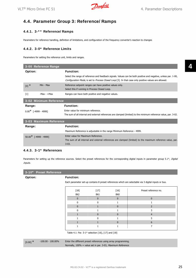
3-00 Reference Range
Option: Function:Select the range of reference and feedback signals. Values can be both positive and negative, unless par. 1-00,
Configuration Mode, is set to Process Closed Loop [3]. In that case only positive values are allowed.
[0] * Min - Max Reference setpoint ranges can have positive values only.
Select this if running in Process Closed Loop.
[1] -Max - +Max Ranges can have both positive and negative values.
3-02 Minimum Reference
Range: Function:
0.00* [-4999 - 4999] Enter value for minimum reference.
The sum of all internal and external references are clamped (limited) to the minimum reference value, par. 3-02.
3-03 Maximum Reference
Range: Function:Maximum Reference is adjustable in the range Minimum Reference - 4999.
50.00* [-4999 - 4999] Enter value for Maximum Reference.
The sum of all internal and external references are clamped (limited) to the maximum reference value, par.
3-03.
4.4.3. 3-1* References
Parameters for setting up the reference sources. Select the preset references for the corresponding digital inputs in parameter group 5.1*, Digital
Inputs.
3-10* Preset Reference
Option: Function:Each parameter set-up contains 8 preset references which are selectable via 3 digital inputs or bus.
[18]
Bit2
[17]
Bit1
[16]
Bit0
Preset reference no.
0 0 0 0
0 0 1 1
0 1 0 2
0 1 1 3
1 0 0 4
1 0 1 5
1 1 0 6
1 1 1 7
Table 4.1: Par. 5-1* selection [16], [17] and [18]
[0.00] * -100.00 - 100.00% Enter the different preset references using array programming.
Normally, 100% = value set in par. 3-03, Maximum Reference.
VLT® Micro Drive FC 51 4. Parameter Descriptions
MG.02.C4.02 - VLT® is a registered Danfoss trademark 25
4

However, there are exceptions if par. 3-00 is set to Min - Max, [0].
Example 1:
Par. 3-02 is set to 20 and par. 3-03 is set to 50. In this case 0% = 0 and 100% = 50.
Example 2:
Par. 3-02 is set to -70 and par. 3-03 is set to 50. In this case 0% = 0 and 100% = 70.
3-11 Jog Speed [Hz]
Range: Function:Jog speed is a fixed output speed and overrules the selected reference speed, see par. 5-1* selection [14].
If the motor is stopped while in jog mode, the jog signal acts as a start signal.
Removing the jog signal makes the motor run according to the selected configuration.
5.0 Hz [0.0 - 400.0 Hz] Select speed to function as jog speed.
3-12 Catch Up/Slow Down Value
Range: Function:
0% * [0 - 100%] The Catch-up/Slowdown function is activated by an input command (see par. 5-1*, choice [28]/[29]). If the
command is active, the Catch-up/Slowdown value (in %) is added to the reference function as follows:
Reference = Reference + Reference × Catchup Slowdown100
Reference = Reference − Reference × Catchup Slowdown100
When the input command is inactivated, the reference returns to its original value ie. Reference = Reference +
0.
3-14 Preset Relative Reference
Range: Function:0.00% [-100.00 - 100.00%] Define fixed value in % to be added to variable value defined in par. 3-18, Relative Scaling Reference Source.
The sum of fixed and variable values (labelled Y in illustration below) is multiplied with actual reference (labelled
X in illustation). This product is added to actual reference X + X × Y100
3-15 Reference 1 Source
Option: Function:Par. 3-15, 3-16 and 3-17 define up to three different reference signals. The sum of these reference signals
defines the actual reference.
[0] No Function No reference signal is defined.
[1] * Analog Input 53 Use signals from analog input 53 as reference, see par. 6-1*.
[2] Analog Input 60 Use signals from analog input 60 as reference, see par. 6-2*.
[8] Pulse input 33 Use signals from pulse input as reference, see par. 5-5*.
[11] Local Bus Reference Use signals from local bus as reference, see par. 8-9*.
[21] LCP Potentiometer Use signals from LCP potentiometer as reference, see par. 6-8*.
3-16 Reference 2 Source
Option: Function:See Par. 3-15 for description.
[0] No Function No reference signal is defined.
[1] Analog Input 53 Use signals from analog input 53 as reference.
4. Parameter Descriptions VLT® Micro Drive FC 51
26 MG.02.C4.02 - VLT® is a registered Danfoss trademark
4

[2] * Analog Input 60 Use signals from analog input 60 as reference.
[8] Pulse input 33 Use signals from pulse input as reference, see par. 5-5*.
[11] Local Bus Reference Use signals from local bus as reference.
[21] LCP Potentiometer Use signals from LCP potentiometer as reference.
3-17 Reference 3 Source
Option: Function:See Par. 3-15 for description.
[0] No Function No reference signal is defined.
[1] Analog Input 53 Use signals from analog input 53 as reference.
[2] Analog Input 60 Use signals from analog input 60 as reference.
[8] Pulse input 33 Use signals from pulse input as reference, see par. 5-5*.
[11] * Local Bus Reference Use signals from local bus as reference.
[21] LCP Potentiometer Use signals from LCP potentiometer as reference.
3-18 Relative Scaling Reference Source
Option: Function:Select the source for a variable value to be added to the fixed value defined in par. 3-14, Preset Relative Ref-
erence.
[0] * No Function The function is disabled
[1] Analog Input 53 Select analog input 53 as relative scaling reference source.
[2] Analog Input 60 Select analog input 54 as relative scaling reference source.
[8] Pulse Input 33 Select pulse input 33 as relative scaling reference source.
[11] Local Bus Reference Select local bus ref. as relative scaling reference source.
[21] LCP Potentiometer Select LCP potentiometer as relative scaling reference source.
4.4.4. 3-4* Ramp 1
A linear ramp is characterized by ramping up at a constant speed until the desired motor speed has been reached. Some overshoot may be experienced
when reaching speed, which may cause speed jerks for a short while before stabilizing.
An S-ramp accelerates more smoothly thus compensating for jerks when the speed is reached.
See the below figure for a comparison of the two ramp types.
Ramp Times:
Ramp up: Acceleration time from 0 to nominal motor frequency (par. 1-23).
Deceleration time from nominal motor frequency (par. 1-23) to 0.
VLT® Micro Drive FC 51 4. Parameter Descriptions
MG.02.C4.02 - VLT® is a registered Danfoss trademark 27
4

Limitation:
Too short ramp up time can result in Torque limit warning (W12) and/or DC over voltage warning (W7). Ramping is stopped when the frequency converter
has reached Torque limit motor mode (par. 4-16).
Too short ramp down time can result in Torque limit warning (W12) and/or DC over voltage warning (W7). Ramping is stopped when the frequency
converter reaches the Torque limit generator mode (par. 4-17) and/or the internal DC over voltage limit.
3-40 Ramp1 Type
Option: Function:
[0] * Linear Constant acceleration/deceleration.
[2] S-ramp Smooth jerk compensated acceleration/deceleration.
3-41 Ramp1 Ramp-up Time
Range: Function:
3.00 s* [0.05 - 3600.00 s ] Enter ramp-up time from 0 Hz to rated motor frequency (fM,N) set in par. 1-23.
Choose a ramp-up time ensuring that torque limit is not exceeded, see par. 4-16.
3-42 Ramp1 Ramp-down Time
Range: Function:
3.00* [0.05 - 3600.00 s] Enter ramp down time from rated motor frequency (fM,N) in par. 1-23 to 0 Hz.
Choose a ramp down time that does not cause over-voltage in inverter due to regenerative operation of motor.
Furthermore, regenerative torque must not exceed limit set in par. 4-17.
4.4.5. 3-5* Ramp2
See par. 3-4* for a description of ramp types.
NB!
Ramp2 - alternative ramp times:
Changing from Ramp1 to Ramp2 is done via the digital input. See par. 5-1*, selection [34].
3-50 Ramp2 Type
Option: Function:
[0] * Linear Constant acceleration/deceleration.
[2] S-ramp Smooth jerk compensated acceleration/deceleration.
3-51 Ramp2 Ramp-up Time
Range: Function:
3.00 s* [0.05 - 3600.00 s] Enter ramp-up time from 0 Hz to rated motor frequency (fM,N) set in par. 1-23.
Choose a ramp-up time ensuring that torque limit is not exceeded, see par. 4-16.
3-52 Ramp2 Ramp-down Time
Range: Function:3.00 s [0.05 - 3600.00 s] Enter ramp down time from rated motor frequency (fM,N) in par. 1-23 to 0 Hz.
Choose a ramp down time that does not cause over-voltage in inverter due to regenerative operation of motor.
Furthermore, regenerative torque must not exceed limit set in par. 4-17.
4.4.6. 3-8* Other Ramps
This section contains parameters for Jog and Quick Stop Ramps.
With a Jog Ramp you can both ramp up and down whereas you can only ramp down with the Quick Stop Ramp.
4. Parameter Descriptions VLT® Micro Drive FC 51
28 MG.02.C4.02 - VLT® is a registered Danfoss trademark
4

3-80 Jog Ramp Time
Range: Function:
3.00 s* [0.05 - 3600.00 s] A linear ramp applicable when Jog is activated. See par. 5-1*, selection [14].
Ramp up time = Ramp down time.
Jog Ramp time starts upon activation of a jog signal via a selected digital input or serial communication port.
3-81 Quick Stop Ramp Time
Range: Function:
3.00 s* [0.05 - 3600.00 s] A linear ramp applicable when Q-stop is activated. See par. 5-1*, selection [4].
VLT® Micro Drive FC 51 4. Parameter Descriptions
MG.02.C4.02 - VLT® is a registered Danfoss trademark 29
4

4.5. Parameter Group 4: Limits/Warnings
4.5.1. 4-** Motor Limits
Parameter group for configuring limits and warning.
4.5.2. 4-1* Motor Limits
Use these parameters for defining the speed, torque and current working range for the motor.
4-10 Motor Speed Direction
Option: Function:If terminals 96, 97 and 98 are connected to U, V and W respectively, the motor runs clockwise when seen from
the front.
NB!
This parameter cannot be adjusted while the motor is running
[0] Clockwise The motor shaft rotates in clockwise direction. This setting prevents the motor from running in counterclockwise
direction.
If par. 1-00 Configuration mode has been set to Process Closed Loop [3] this parameter must always be set to
Clockwise.
[1] Counterclockwise The motor shaft rotates in counterclockwise direction. This setting prevents the motor from running in clockwise
direction.
[2] * Both With this setting the motor can run in both directions. However, the output frequency is limited to the range:
Motor Speed Low Limit (par. 4-12) to Motor Speed High Limit (par. 4-14).
4-12 Motor Speed Low Limit
Range: Function:
0.0 Hz* [0.0 - 400.0 Hz] Set the Minimum Motor Speed Limit corresponding to the minimum output frequency of the motor shaft.
NB!
As the minimum output frequency is an absolute value, it cannot be deviated from.
4-14 Motor Speed High Limit
Range: Function:
65.0 Hz* [0.0 - 400.0 Hz] Set the Maximum Motor Speed corresponding to the maximum output frequency of the motor shaft.
NB!
As the maximum output frequency is an absolute value, it cannot be deviated from.
4-16 Torque Limit in Motor Mode
Range: Function:
150 %* [0 - 400%] Set the torque limit for motor operation.
The setting is not automatically reset to default when changing settings in par. 1-00 to 1-25 Load & Motor .
4-17 Torque Limit in Generator Mode
Range: Function:
100 %* [0 - 400%] Set the torque limit for generator mode operation.
The setting is not automatically reset to default when changing settings in par. 1-00 to 1-25 Load & Motor .
4. Parameter Descriptions VLT® Micro Drive FC 51
30 MG.02.C4.02 - VLT® is a registered Danfoss trademark
4

4.5.3. 4-5* Adjustable Warnings
Parameter group containing adjustable warning limits for current, speed, reference and feedback.
Warnings are shown in display, programmed output or serial bus.
4-50 Warning Current Low
Range: Function:Use this parameter to set a lower limit for the current range.
If current drops below the set limit, warning bit 8 is set in par. 16-94.
Output Relay can be configured to indicate this warning. LCP warning light does not light when this parameter's
set limit is reached.
0.00 A* [0.00 - 26.00 A] Set value for low current limit.
4-51 Warning Current High
Range: Function:Use this parameter to set an upper limit for the current range.
If current exceeds the set limit, warning bit 7 is set in par. 16-94.
Output Relay can be configured to indicate this warning. LCP warning light does not light when this parameter's
set limit is reached.
26.00 A* [0.00 - 26.00 A] Set upper current limit.
4-58 Missing Motor Phase Function
Option: Function:A missing motor phase causes the motor torque to drop. This monitor may be disabled for special purposes (eg.
small motors running pure U/f mode), but as there is a risk of overheating the motor, Danfoss strongly recom-
mends that the function is On.
A missing motor phases causes the frequency converter to trip and report an alarm.
NB!
This parameter cannot be changed while motor runs.
[0] Off Function is disabled.
[1] * On Function is enabled.
4.5.4. 4-6* Speed Bypass
In some applications mechanical resonance may occur. Avoid resonance points by creating a bypass. The frequency converter ramps through the bypass
area thereby passing mechanical resonance points quickly.
4-61 Speed Bypass From [Hz]
Range: Function:
Array [2]
0.0 Hz* [0.0 - 400.0 Hz] Enter either the lower or upper limit of the speeds to be avoided.
It does not matter whether Bypass From or Bypass To is the upper or lower limit, however the Speed Bypass
function is disabled if the two parameters are set to the same value.
VLT® Micro Drive FC 51 4. Parameter Descriptions
MG.02.C4.02 - VLT® is a registered Danfoss trademark 31
4

4-63 Speed Bypass To [Hz]
Range: Function:
Array [2]
0.0 Hz* [0.0 - 400.0 Hz] Enter either the upper or lower limit of the speed area to be avoided.
Make sure to enter the opposite limit of that in par. 4-61 Speed Bypass From [Hz].
4. Parameter Descriptions VLT® Micro Drive FC 51
32 MG.02.C4.02 - VLT® is a registered Danfoss trademark
4

4.6. Parameter Group 5: Digital In/Out
4.6.1. 5-** Digital In/Out
The following describes all digital input command functions and signals.
4.6.2. 5-1* Digital Inputs
Parameters for configuring the functions for the input terminals.
The digital inputs are used for selecting various functions in the frequency converter. All digital inputs can be set to the following:
[0] No Operation The frequency converter will not react to signals transmitted to the terminal.
[1] Reset Reset the frequency converter after a Trip/Alarm. Not all alarms can be reset.
[2 ] Coast Inverse Coasting stop, inverted input (NC). The frequency converter leaves the motor in free mode.
[3] Coast and reset inv. Reset and coasting stop inverted input (NC). The frequency converter resets and leaves the motor in free mode.
[4] Quick stop inverse Inverted input (NC). Generates a stop in accordance with the quick-stop ramp time set in par. 3-81. When motor
stops, shaft is in free mode.
[5] DC-brake inv. Inverted input for DC braking (NC). Stops motor by energizing it with DC current for a certain time period, see
par. 2-01. Function is only active when value in par. 2-02 is different from 0.
[6] Stop inv. Stop inverted function. Generates stop function when selected terminal goes from logical level “1” to “0”. Stop
is performed according to selected ramp time.
[8] Start Select start for a start/stop command.
1 = Start, 0 = stop.
[9] Latched start Motor starts if a pulse is applied for min. 2 ms. Motor stops when Stop inverse is activated.
[10] Reversing Change direction of motor shaft rotation. Reversing signal only changes direction of rotation; it does not activate
start function. Select Both directions [2] in par. 4.10.
0 = normal, 1 = reversing.
[11] Start reversing Use for start/stop and for reversing at the same time. Signals on start [8] are not allowed at the same time.
0 = stop, 1 = start reversing.
[12] Enable start forward Use if motor shaft must rotate clockwise at start.
[13] Enable start reverse Use if motor shaft must rotate counterclockwise at start.
[14] Jog Use for activating jog speed. See par. 3-11.
[16] Preset ref bit 0 Preset ref bit 0, 1 and 2 enables a choice between one of the eight preset references according to the table
below.
[17] Preset ref bit 1 Same as preset ref bit 0 [16], see par. 3-10.
[18] Preset ref bit 2 Same as preset ref bit 0 [16].
[19] Freeze reference Freeze actual reference. The frozen reference is now the point of enable/condition for Speed up and Speed down
to be used. If Speed up/down is used, speed change always follows ramp 2 (par. 3-51 and 3-52) in the range
par. 3-02 Minimum Reference - par. 3-03 Maximum Reference.
[20] Freeze output Freeze the actual motor frequency (Hz). The frozen motor frequency is now the point of enable/condition for
Speed up and Speed down to be used. If Speed up/down is used, the speed change always follows ramp 2 in
the range par. 4-12, Motor Speed Low Limit - par. 4-14, Motor Speed High Limit.
NB!
When freeze output is active, the frequency converter cannot be stopped via a low Start [8]
signal. Stop the frequency converter via a terminal programmed for Coasting Inverse [2] or
Coast and reset, inverse [3].
[21] Speed up Select Speed up and Speed down if digital control of the up/down speed is desired (motor potentiometer).
Activate this function by selecting either Freeze reference or Freeze output. When Speed up is activated for less
than 400 ms. the resulting reference will be increased by 0.1%. If Speed up is activated for more than 400 ms.
the resulting reference will ramp according to ramp 2 in par. 3-51.
[22] Speed down Same as Speed up [21].
VLT® Micro Drive FC 51 4. Parameter Descriptions
MG.02.C4.02 - VLT® is a registered Danfoss trademark 33
4

[23] Setup select bit 0 Set par. 0-10 Active set-up to Multi set-up.
Logic 0 = set-up 1, Logic 1 = Set-up 2.
[26] Precise stop inverse
(only terminal 33)
Prolong the stop signal to give a precise stop independent of scan time. The function is available for terminal
33 only.
[27] Start, precise stop (on-
ly terminal 33)
As [26], but including Start.
[28] Catch up Select Catch up/Slow down to increase or reduce the resulting reference value by the percentage set in par.
3-12.
[29] Slow down Same as Catch up [28]
[32] Pulse input (only termi-
nal 33)
Select Pulse input when using a pulse sequence as either reference or feedback. Scaling is done in par. group
5-5*.
[34] Ramp bit 0 Logic 0 = Ramp1, see par. 3-4*.
Logic 1 = Ramp2, see par. 3-5*.
[60] Counter A (up) Input for counter A.
[61] Counter A (down) Input for counter A.
[62] Reset counter A Input for reset of counter A.
[63] Counter B (up) Input for counter B.
[64] Counter B (down) Input for counter B.
[65] Reset counter B Input for reset of counter B.
5-10 Terminal 18 Digital Input
Option: Function:
[8] * Start Select function from available digital input range.
See par. 5-1* for choices.
5-11 Terminal 19 Digital Input
Option: Function:
[10] * Reversing Select function from available digital input range.
See par. 5-1* for choices.
5-12 Terminal 27 Digital Input
Option: Function:
[1] * Reset Select function from available digital input range.
See par. 5-1* for choices.
5-13 Terminal 29 Digital Input
Option: Function:
[14] * Jog Select function from available digital input range.
See par. 5-1* for choices.
5-15 Terminal 33 Digital Input
Option: Function:
[16] * Preset bit 0 Select function from available digital input range.
See par. 5-1* for choices.
4.6.3. 5-4* Relays
Parameter group for configuring timing and output functions for relays.
[0] No Operation Default for all digital and relay outputs.
[1] Control Ready Control board receives supply voltage.
[2] Drive Ready Frequency converter is ready for operation and applies supply signal on control board.
[3] Drive Ready, Remote Frequency converter is ready for operation in Auto On-mode.
4. Parameter Descriptions VLT® Micro Drive FC 51
34 MG.02.C4.02 - VLT® is a registered Danfoss trademark
4

[4] Enable/No Warning Frequency converter is ready for operation. No start or stop command is given. No warnings are present.
[5] Drive Running Motor is running.
[6] Running/No Warning Motor runs, and no warning are present.
[7] Run in Range/No
Warning
Motor runs within programmed current ranges, see parameters 4-50 and 4-51. No warnings are present.
[8] Run on ref/No Warning Motor runs at reference speed.
[9] Alarm An alarm activates output.
[10] Alarm on Warning An alarm or warning activates output.
[12] Out of Current Range Motor current is outside range set in parameters 4-50 and 4-51.
[13] Below Current, low Motor current is lower than set in par. 4-50.
[14] Above Current, high Motor current is higher than set in par. 4-51.
[21] Thermal Warning Thermal warning is present when temperature exceeds limit in motor, frequency converter, brake resistor or
thermistor.
[22] Ready, No Thermal
Warning
Frequency converter is ready for operation and no over-temperature warning is present.
[23] Remote Ready, No
Thermal Warning
Frequency converter is ready for operation in Auto mode, and no over-temperature warning is present.
[24] Ready, Voltage OK Frequency converter is ready for operation and mains voltage is within specified voltage range.
[25] Reverse Motor runs/is ready to run clockwise when logic = 0 and counter clockwise when logic = 1. Output changes as
soon as reversing signal is applied.
[26] Bus OK Active communication (no time-out) via serial communication port.
[28] Brake, No Warn Brake is active, and no warnings are present.
[29] Brake Ready/No Fault Brake is ready for operation, and no faults are present.
[30] Brake Fault (IGBT) Protects frequency converter if fault on brake modules is present. Use relay to cut out main voltage from fre-
quency converter.
[32] Mech. Brake Control Enables control of external mechanical brake, see parameter group 2-2*.
[36] Control Word Bit 11 Bit 11 in control word controls relay.
[51] Local Ref Active
[52] Remote Ref Active
[53] No Alarm
[54] Start Cmd Active
[55] Running Reverse
[56] Drive in Hand Mode
[57] Drive in Auto Mode
[60] Comparator 0 See par. group 13-1*. If comparator 0 is evaluated as TRUE, output goes high. Otherwise, it is low.
[61] Comparator 1 See par. group 13-1*. If comparator 1 is evaluated as TRUE, output goes high. Otherwise, it is low.
[62] Comparator 2 See par. group 13-1*. If comparator 2 is evaluated as TRUE, output goes high. Otherwise, it is low.
[63] Comparator 3 See par. group 13-1*. If comparator 3 is evaluated as TRUE, output goes high. Otherwise, it is low.
[70] Logic Rule 0 See par. 13-4*. If Logic Rule 1 is evaluated as TRUE, output goes high. Otherwise, it is low.
[71] Logic Rule 1 See par. 13-4*. If Logic Rule 2 is evaluated as TRUE, output goes high. Otherwise, it is low.
[72] Logic Rule 2 See par. 13-4*. If Logic Rule 3 is evaluated as TRUE, output goes high. Otherwise, it is low.
[73] Logic Rule 3 See par. 13-4*. If Logic Rule 3 is evaluated as TRUE, output goes high. Otherwise, it is low.
[81] SL Digital Output B See par. 13-52 SL Control Action. When Smart Logic Action Set dig. out. A high [39] is executed, input goes
high. When Smart Logic Action Set dig. out. A low [33] is executed, input goes low.
5-40 Function Relay
Option: Function:
[0] * No Operation Select function from available relay output range.
VLT® Micro Drive FC 51 4. Parameter Descriptions
MG.02.C4.02 - VLT® is a registered Danfoss trademark 35
4

4.6.4. 5-5* Pulse Input
Set par. 5-15 to choice [32] pulse input. Now terminal 33 handles a pulse input in the range from Low frequency, par. 5-55, to High frequency, par. 5-56.
Scale frequency input via par. 5-57 and par. 5-58.
5-55 Terminal 33 Low Frequency
Range: Function:
20 Hz* [20 - 4999 Hz] Enter low frequency corresponding to low motor shaft speed (i.e. low reference value) in par. 5-57.
5-56 Terminal 33 High Frequency
Range: Function:
5000 Hz* [21 - 5000 Hz] Enter high frequency corresponding to high motor shaft speed (i.e. high reference value) in par. 5-58.
5-57 Terminal 33 Low Ref./Feedb. Value
Range: Function:
0.000* [-4999 - 4999] Set reference/feedback value corresponding to low pulse frequency value set in par. 5-55.
5-58 Terminal 33 High Ref./Feedb. Value
Range: Function:
50.000* [-4999 - 4999] Set reference/feedback value corresponding to high pulse frequency value set in par. 5-56.
4. Parameter Descriptions VLT® Micro Drive FC 51
36 MG.02.C4.02 - VLT® is a registered Danfoss trademark
4

4.7. Parameter Group 6: Analogue In/Out
4.7.1. 6-** Analog In/Out
Parameter group for configuring analog inputs and outputs.
4.7.2. 6-0* Analog I/O Mode
Parameter group for setting up the analog I/O configuration.
6-00 Live Zero Timeout Time
Range: Function:The Live Zero function is used for monitoring the signal on an analog input. If the signal disappears, a Live
Zero warning is reported.
10 s [1 - 99 s] Set delay time before Live Zero Timeout Function is applied (par. 6-01).
If the signal reappears during the set delay, timer will be reset.
When live zero is detected, the frequency converter freezes output frequency and starts Live Zero Timeout timer.
6-01 Live Zero Timeout Function
Option: Function:Function is activated if input signal is below 50% of value set in parameters 6-10, 6-12 or 6-22.
[0] * Off Function is disabled.
[1] Freeze output Output frequency remains at value it had when live zero was detected.
[2] Stop Frequency converter ramps down to 0 Hz. Remove live zero error condition before restarting frequency con-
verter.
[3] Jogging Frequency converter ramps to jog speed, see par. 3-41.
[4] Max Speed Frequency converter ramps to Motor Speed High Limit, see par. 4-14.
[5] Stop and Trip Frequency converter ramps down to 0 Hz and then trips. Remove live zero condition and activate reset before
restarting the frequency converter.
4.7.3. 6-1* Analog Input 1
Parameters for configuring scaling and limits for analog input 1 (terminal 53).
NB!
Micro switch 4 in position U:
Parameters 6-10 and 6-11 are active.
Micro switch in position I:
Parameters 6-12 and 6-13 are active.
See VLT® Micro Drive FC 51 Quick Guide
VLT® Micro Drive FC 51 4. Parameter Descriptions
MG.02.C4.02 - VLT® is a registered Danfoss trademark 37
4

6-10 Terminal 53 Low Voltage
Range: Function:This scaling value should correspond to minimum reference value set in par. 6-14. See also section Reference
Handling.
0.07 V* [0.00 - 9.90 V] Enter low voltage value.
The value must be set to min. 1V in order to activate the Live Zero Timeout function in par. 6-01.
6-11 Terminal 53 High Voltage
Range: Function:This scaling value should correspond to maximum reference value set in par. 6-15.
10.0 V* [0.10 - 10.00 V] Enter high voltage value.
6-12 Terminal 53 Low Current
Range: Function:This reference signal should correspond to minimum reference value set in par. 3-02.
0.14 mA* [0.00 - 19.90 mA] Enter low current value.
The value must be set to min. 2 mA in order to activate the Live Zero Timeout function in par. 6-01.
6-13 Terminal 53 High Current
Range: Function:This reference signal should correspond to the maximum reference value set in par. 6-15.
20.00 mA* [0.10 - 20.00 mA] Enter high current value.
6-14 Terminal 53 Low Ref./Feedb. Value
Range: Function:The scaling value corresponding to the low voltage/low current set in parameters 6-10 and 6-12.
0.000* [-4999 - 4999] Enter analog input scaling value.
4. Parameter Descriptions VLT® Micro Drive FC 51
38 MG.02.C4.02 - VLT® is a registered Danfoss trademark
4

6-15 Terminal 53 High Ref./Feedb. Value
Range: Function:The scaling value corresponding to the maximum reference feedback value set in parameters 6-11 and 6-13.
50.000* [-4999.000 - 4999.000] Enter analog input scaling value.
6-16 Terminal 53 Filter Time Constant
Range: Function:A first-order digital low pass filter time constant for suppressing electrical noise in terminal 53. A high time
constant value improves dampening but also increases time delay through the filter.
0.01 s* [0.01 - 10.00 s] Enter time constant.
6-19 Terminal 53 Mode
Option: Function:Select the input to be present on terminal 53.
Par. 6-19 MUST be set according to Micro switch 4 setting.
[0] * Voltage Mode
[1] Current Mode
4.7.4. 6-2* Analog Input 2
Parameters for configuring scaling and limits for analog input 2, terminal 60.
6-22 Terminal 60 Low Current
Range: Function:This reference signal should correspond to minimum reference value set in par. 3-02.
0.14 mA* [0.00 - 19.90 mA] Enter low current value.
The value must be set to min. 2 mA in order to activate the Live Zero Timeout function in par. 6-01.
6-23 Terminal 60 High Current
Range: Function:This reference signal should correspond to the high current value set in par. 6-25.
20.00 mA* [0.10 - 20.00 mA] Enter high current value.
6-24 Terminal 60 Low Ref./Feedb. Value
Range: Function:The scaling value should correspond to the minimum reference feedback value set in par. 3-02.
0.000* [-4999 - 4999] Enter analog input scaling value.
6-25 Terminal 60 High Ref./Feedb. Value
Range: Function:The scaling value should correspond to the maximum reference feedback value set in par. 3-03.
50.00* [-4999 - 4999] Enter analog input scaling value.
VLT® Micro Drive FC 51 4. Parameter Descriptions
MG.02.C4.02 - VLT® is a registered Danfoss trademark 39
4

6-26 Terminal 60 Filter Time Constant
Range: Function:A first-order digital low pass filter time constant for suppressing electrical noise in terminal 54. A high time
constant value improves dampening, but also increases time delay through the filter.
NB!
This parameter cannot be changed while motor runs.
0.01 s* [0.01 - 10.00 s] Enter time constant.
4.7.5. 6-8* LCP Potentiometer
The LCP potentiometer can be selected either as Reference Resource or Relative Reference Resource.
NB!
In Hand mode the LCP potentiometer functions as local reference.
6-81 LCP Potentiometer Low Ref. Value
Range: Function:The scaling value corresponding to 0.
0.000* [-4999 - 4999] Enter low reference value.
The reference value corresponding to potentiometer turned fully counterclockwise (0 degrees).
6-82 LCP Potentiometer High Ref. Value
Range: Function:The scaling value corresponding to the maximum reference feedback value set in par. 3-03.
50.00* [-4999 - 4999] Enter high reference value.
The reference value corresponding to potentiometer turned fully clockwise (200 degrees).
4.7.6. 6-9* Analog Output
These parameters are for configuring the analog outputs of the frequency converter.
6-90 Terminal 42 Mode
Option: Function:
[0] * 0 - 20 mA Range for analog outputs is 0-20 mA
[1] 4-20 mA Range for analog outputs is 4 - 20 mA
[2] Digital Functions as slow reacting digital output. Set value to either 0 mA (off) or 20 mA (on), see par. 6-92.
6-91 Terminal 42 Analog Output
Option: Function:Select the function for terminal 42 as an analog output.
[0] * No Operation
[10] Output Frequency
[11] Reference
[12] Feedback
[13] Motor Current
[16] Power
[20] Bus Control
4. Parameter Descriptions VLT® Micro Drive FC 51
40 MG.02.C4.02 - VLT® is a registered Danfoss trademark
4

6-92 Terminal 42 Digital Output
Option: Function:See par. 5-4*, Relays, for choices and descriptions.
[0] * No Operation
[80] SL Digital Output A See par. 13-52 SL Control Action. When Smart Logic Action Set dig. out. A high [38] is executed, input goes
high. When Smart Logic Action Set dig. out. A low [32] is executed, input goes low.
6-93 Terminal 42 Output Min. Scale
Range: Function:0.00 % [0.00 - 200.0%] Scale minimum output of selected analog signal at terminal 42 as percentage of maximum signal value. E.g. if 0
mA (or 0 Hz) is desired at 25% of maximum output value, programme 25%. Scaling values up to 100% can
never be higher than corresponding setting in par. 6-52.
6-94 Terminal 42 Output Max. Scale
Range: Function:
100.00%* [0.00 - 200.00%] Scale maximum output of selected analog signal at terminal 42. Set value to maximum value of current signal
output. Scale output to give a current lower than 20 mA at full scale; or 20 mA at an output below 100% of
maximum signal value.
If 20 mA is the desired output current at a value between 0 - 100% of the full-scale output, programme per-
centage value in the parameter, i.e. 50% = 20 mA. If a current between 4 and 20 mA is desired at maximum
output (100%), calculate percentage value as follows:
20 mAdesired maximum current × 100 %
i.e.
10 mA = 2010 × 100 = 200 %
VLT® Micro Drive FC 51 4. Parameter Descriptions
MG.02.C4.02 - VLT® is a registered Danfoss trademark 41
4

4.8. Parameter Group 7: Controllers
4.8.1. 7-** Controllers
Parameters group for configuring application controls.
4.8.2. 7-2* Process Ctrl. Feedb
Select feedback sources and handling for Process PI Control.
NB!
Set par. 3-15 to [0] No Function in order to use Analog Input as a feedback signal.
7-20 Process CL Feedback Resources
Option: Function:Select input to function as feedback signal.
[0] * No Function
[1] Analog Input 53
[2] Analog Input 60
[8] Pulse Input 33
[11] Local Bus Ref.
4.8.3. 7-3* Process PI Control
7-30 Process PI Normal/Inverse Control
Option: Function:
[0] * Normal Feedback larger than setpoint result in a speed reduction.
Feedback less than setpoint result in a speed increase.
[1] Inverse Feedback larger than setpoint result in a speed increase.
Feedback less than setpoint result in a speed reduction.
7-31 Process PI Anti Windup
Option: Function:[0] Disable Regulation of a given error will continue even when the output frequency cannot be increased/decreased.
[1] * Enable PI-controller ceases from regulating a given error when the output frequency cannot be increased/decreased.
7-32 Process PI Start Speed
Range: Function:
0.0 Hz* [0.0 - 200.0 Hz] Until the set motor speed has been reached the frequency converter operates in Open Loop mode.
7-33 Process PI Proportional Gain
Option: Function:
[0.01] * 0.00 - 10.00 Enter the value for the P proportional gain, i.e. the multiplication factor of the error between the set point and
the feedback signal.
Note! 0.00 = Off.
7-34 Process PI Integral Time
Range: Function:
9999.00 s* [0.10 - 9999.00 s] The integrator provides an increasing gain at a constant error between the set point and the feedback signal.
The integral time is the time needed by the integrator to reach the same gain as the proportional gain.
4. Parameter Descriptions VLT® Micro Drive FC 51
42 MG.02.C4.02 - VLT® is a registered Danfoss trademark
4

7-38 Process Feed Forward Factor
Range: Function:
0%* [0 - 400%] The FF factor sends a part of the reference signal around the PI controller which then only affects part of the
control signal.
By activating the FF factor less overshoot and high dynamics are gained when changing the setpoint.
This parameter is always active when par. 1-00 Configuration Mode is set to Process [3].
7-39 On Reference Bandwidth
Range: Function:5% [0 - 200% ] Enter the value for the On Reference Bandwidth.
The PI control error is the difference between setpoint and feedback and when this is less than the value set in
this parameter the On Reference is active.
VLT® Micro Drive FC 51 4. Parameter Descriptions
MG.02.C4.02 - VLT® is a registered Danfoss trademark 43
4
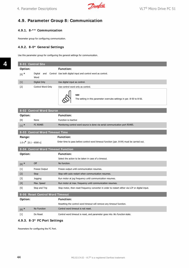
4.9. Parameter Group 8: Communication
4.9.1. 8-** Communication
Parameter group for configuring communication.
4.9.2. 8-0* General Settings
Use this parameter group for configuring the general settings for communication.
8-01 Control Site
Option: Function:
[0] * Digital and Control
Word
Use both digital input and control word as control.
[1] Digital Only Use digital input as control.
[2] Control Word Only Use control word only as control.
NB!
The setting in this parameter overrules settings in par. 8-50 to 8-56.
8-02 Control Word Source
Option: Function:[0] None Function is inactive
[1] * FC RS485 Monitoring control word source is done via serial communication port RS485.
8-03 Control Word Timeout Time
Range: Function:
1.0 s* [0.1 - 6500 s] Enter time to pass before control word timeout function (par. 8-04) must be carried out.
8-04 Control Word Timeout Function
Option: Function:Select the action to be taken in case of a timeout.
[0] * Off No function.
[1] Freeze Output Freeze output until communication resumes.
[2] Stop Stop with auto restart when communication resumes.
[3] Jogging Run motor at jog frequency until communication resumes.
[4] Max. Speed Run motor at max. frequency until communication resumes.
[5] Stop and Trip Stop motor, then reset frequency converter in order to restart either via LCP or digital input.
8-06 Reset Control Word Timeout
Option: Function:Resetting the control word timeout will remove any timeout function.
[0] * No Function Control word timeout is not reset.
[1] Do Reset Control word timeout is reset, and parameter goes into No Function state.
4.9.3. 8-3* FC Port Settings
Parameters for configuring the FC Port.
4. Parameter Descriptions VLT® Micro Drive FC 51
44 MG.02.C4.02 - VLT® is a registered Danfoss trademark
4

4.9.4. 8-30 Protocol
8-30 Protocol
Option: Function:Select the protocol to be used. Note that changing protocol will not be effective until after powering off the
frequency converter.
[0] * FC
[2] Modbus RTU
8-31 Address
Range: Function:Select the address for the bus.
1* [1 - 126] FC-bus range is 1-126.
Modbus range is 1-247.
8-32 FC Port Baud Rate
Option: Function:Select baud rate for FC Port.
NB!
Changing baud rate will be effective after responding to any ongoing bus-requests.
[0] 2400 Baud
[1] 4800 Baud
[2] * 9600 Baud
[3] 19200 Baud
[4] 38400 Baud
8-33 FC Port Parity
Option: Function:This parameter only affects Modbus as FC bus always has even parity.
[0] * Even Parity (1 stopbit)
[1] Odd parity
[2] No Parity (1 stopbit) Select this for Modbus RTU
[3] No Parity (2 stopbit)
8-35 Minimum Response Delay
Range: Function:
0.010 s* [0.001 - 0.500 s] Specify minimum delay time between receiving a request and transmitting a response.
8-36 Max Response Delay
Range: Function:
5.000 s* [0.010 - 10.00 s] Specify maximum permissible delay time between transmitting a request and receiving a response. Exceeding
this time delay causes control word timeout.
4.9.5. 8-5* Digital/Bus
Parameters for configuring control word Digital/Bus merging.
VLT® Micro Drive FC 51 4. Parameter Descriptions
MG.02.C4.02 - VLT® is a registered Danfoss trademark 45
4
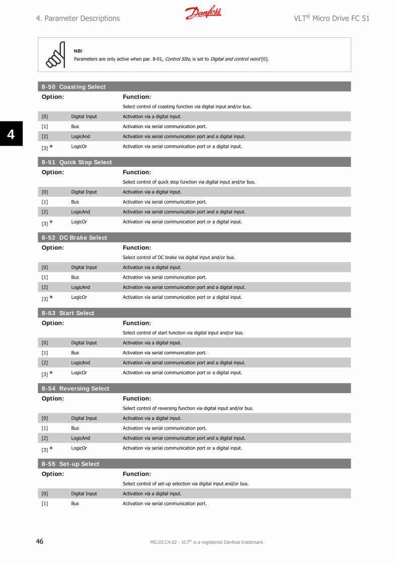
NB!
Parameters are only active when par. 8-01, Control SIte, is set to Digital and control word [0].
8-50 Coasting Select
Option: Function:Select control of coasting function via digital input and/or bus.
[0] Digital Input Activation via a digital input.
[1] Bus Activation via serial communication port.
[2] LogicAnd Activation via serial communication port and a digital input.
[3] * LogicOr Activation via serial communication port or a digital input.
8-51 Quick Stop Select
Option: Function:Select control of quick stop function via digital input and/or bus.
[0] Digital Input Activation via a digital input.
[1] Bus Activation via serial communication port.
[2] LogicAnd Activation via serial communication port and a digital input.
[3] * LogicOr Activation via serial communication port or a digital input.
8-52 DC Brake Select
Option: Function:Select control of DC brake via digital input and/or bus.
[0] Digital Input Activation via a digital input.
[1] Bus Activation via serial communication port.
[2] LogicAnd Activation via serial communication port and a digital input.
[3] * LogicOr Activation via serial communication port or a digital input.
8-53 Start Select
Option: Function:Select control of start function via digital input and/or bus.
[0] Digital Input Activation via a digital input.
[1] Bus Activation via serial communication port.
[2] LogicAnd Activation via serial communication port and a digital input.
[3] * LogicOr Activation via serial communication port or a digital input.
8-54 Reversing Select
Option: Function:Select control of reversing function via digital input and/or bus.
[0] Digital Input Activation via a digital input.
[1] Bus Activation via serial communication port.
[2] LogicAnd Activation via serial communication port and a digital input.
[3] * LogicOr Activation via serial communication port or a digital input.
8-55 Set-up Select
Option: Function:Select control of set-up selection via digital input and/or bus.
[0] Digital Input Activation via a digital input.
[1] Bus Activation via serial communication port.
4. Parameter Descriptions VLT® Micro Drive FC 51
46 MG.02.C4.02 - VLT® is a registered Danfoss trademark
4

[2] LogicAnd Activation via serial communication port and a digital input.
[3] * LogicOr Activation via serial communication port or a digital input.
8-56 Preset Reference Select
Option: Function:Select control of Preset Reference selection via digital input and/or bus.
[0] Digital Input Activation via a digital input.
[1] Bus Activation via serial communication port.
[2] LogicAnd Activation via serial communication port and a digital input.
[3] * LogicOr Activation via serial communication port or a digital input.
4.9.6. 8-9* Bus Feedback
Parameter for configuring bus feedback.
8-94 Bus Feedback 1
Range: Function:
0* [0x8000 - 0x7FFF] Bus feedback is delivered via FC or Modbus by writing the feedback value into this parameter.
VLT® Micro Drive FC 51 4. Parameter Descriptions
MG.02.C4.02 - VLT® is a registered Danfoss trademark 47
4

4.10. Parameter Group 13: Smart Logic
4.10.1. 13-** Programming Features
Smart Logic Control (SLC)is a sequence of user defined actions (par. 13-52 [X]) executed by the SLC when the associated user defined event (par. 13-51
[X]) is set to True.
Events and actions are linked in pairs, meaning that when an event is true, the linked action is carried out. After this the next event is evaluated and its
belonging action carried out and so on. Only one event is evaluated at the time.
If an event is evaluated as False, the SLC takes no action during the scan interval and no other events are evaluated.
It is possible to programme from 1 to 20 events and actions.
When the last event/action has been executed, the sequence starts again from event/action [0].
The drawing shows an example with three events/actions:
Starting and stopping the SLC:
Start the SLC by selecting On [1] in par. 13-00. The SLC starts evaluating Event 0, and if this is evaluated as TRUE, the SLC continues its cycle.
The SLC stops when the Stop Event, par. 13-02, is TRUE. The SLC can also be stopped by selecting Off [0] in par. 13-00.
To reset all SLC parameters select Reset SLC [1] in par. 13-03 and start programming from scratch.
4.10.2. 13-0* SLC Settings
Use SLC settings to activate, deactive and reset the Smart Logic Control.
13-00 SL Controller Mode
Option: Function:
[0] * Off Function is disabled.
4. Parameter Descriptions VLT® Micro Drive FC 51
48 MG.02.C4.02 - VLT® is a registered Danfoss trademark
4

[1] On SLC is active.
13-01 Start Event
Option: Function:Select input to activate Smart Logic Control.
[0] False Enters False in logic rule.
[1] True Enters True in logic rule.
[2] Running See par. 5-4* [5] for description.
[3] InRange See par. 5-4* [7] for description.
[4] OnReference See par. 5-4* [8] for description.
[7] Out of Current Range See par. 5-4* [12] for description.
[8] BelowILow See par. 5-4* [13] for description.
[9] AboveIHigh See par. 5-4* [14] for description.
[16] ThermalWarning See par. 5-4* [21] for description.
[17] MainsOutOfRange Mains voltage is outside the specified voltage range.
[18] Reversing See par. 5-4* [25] for description.
[19] Warning A warning is active.
[20] Alarm_Trip A trip alarm is active.
[21] Alarm_TripLock A trip lock alarm is active.
[22] Comparator 0 Use result of comparator 0 in logic rule.
[23] Comparator 1 Use result of comparator 1 in logic rule.
[24] Comparator 2 Use result of comparator 2 in logic rule.
[25] Comparator 3 Use result of comparator 3 in logic rule.
[26] LogicRule 0 Use result of logic rule 0 in logic rule.
[27] LogicRule 1 Use result of logic rule 1 in logic rule.
[28] LogicRule 2 Use result of logic rule 2 in logic rule.
[29] LogicRule 3 Use result of logic rule 3 in logic rule.
[33] DigitalInput_18 Use value of DI 18 in logic rule.
[34] DigitalInput_19 Use value of DI 19 in logic rule.
[35] DigitalInput_27 Use value of DI 27 in logic rule.
[36] DigitalInput_29 Use value of DI 29 in logic rule.
[38] DigitalInput_33
[39] * StartCommand This event is True, if frequency converter is started by any means (digital input or other).
[40] DriveStopped This event is True, if frequency converter is stopped or coasted by any means (digital input or other).
13-02 Stop Event
Option: Function:Select input to activate Smart Logic Control.
[0] False Enters False in logic rule.
[1] True Enters True in logic rule.
[2] Running See par. 5-4* [5] for description.
[3] InRange See par. 5-4* [7] for description.
[4] OnReference See par. 5-4* [8] for description.
[7] Out of Current Range See par. 5-4* [12] for description.
[8] BelowILow See par. 5-4* [13] for description.
[9] AboveIHigh See par. 5-4* [14] for description.
[16] ThermalWarning See par. 5-4* [21] for description.
[17] MainsOutOfRange Mains voltage is outside the specified voltage range.
VLT® Micro Drive FC 51 4. Parameter Descriptions
MG.02.C4.02 - VLT® is a registered Danfoss trademark 49
4

[18] Reversing See par. 5-4* [25] for description.
[19] Warning A warning is active.
[20] Alarm_Trip A trip alarm is active.
[21] Alarm_TripLock A trip lock alarm is active.
[22] Comparator 0 Use result of comparator 0 in logic rule.
[23] Comparator 1 Use result of comparator 1 in logic rule.
[24] Comparator 2 Use result of comparator 2 in logic rule.
[25] Comparator 3 Use result of comparator 3 in logic rule.
[26] LogicRule 0 Use result of logic rule 0 in logic rule.
[27] LogicRule 1 Use result of logic rule 1 in logic rule.
[28] LogicRule 2 Use result of logic rule 2 in logic rule.
[29] LogicRule 3 Use result of logic rule 3 in logic rule.
[30] SL Timeout0 Use result of timer 0 in logic rule.
[31] SL Timeout1 Use result of timer 1 in logic rule.
[32] SL Timeout2 Use result of timer 2 in logic rule.
[33] DigitalInput_18 Use value of DI 18 in logic rule.
[34] DigitalInput_19 Use value of DI 19 in logic rule.
[35] DigitalInput_27 Use value of DI 27 in logic rule.
[36] DigitalInput_29 Use value of DI 29 in logic rule.
[38] DigitalInput_33
[39] StartCommand This event is True, if frequency converter is started by any means (digital input or other).
[40] * DriveStopped This event is True, if frequency converter is stopped or coasted by any means (digital input or other).
13-03 Reset SLC
Option: Function:
[0] * Do Not Reset Retains all settings programmed in parameter group 13.
[1] Reset SLC Reset all group 13 parameters to default settings.
4.10.3. 13-1* Comparators
Comparators are used for comparing continuous variables (i.e. output frequency, output current, analog input etc.) to fixed preset values. In addition,
there are digital values that will be compared to fixed time values. See explanation in par. 13-10. Comparators are evaluated once in each scan interval.
Use the result (TRUE or FALSE) directly. All parameters in this parameter group are array parameters with index 0 to 5. Select index 0 to programme
Comparator 0, select index 1 to programme Comparator 1, and so on.
13-10 Comparator Operand
Array [4]
Select variable to be monitored by comparator.
[0] * Disabled Comparator is disabled.
[1] Reference Resulting remote reference (not local) as a percentage.
[2] Feedback Feedback in [Hz].
[3] MotorSpeed Motor speed in Hz.
[4] MotorCurrent Motor current in [A].
[6] MotorPower Motor power in either [kW] or [hp].
[7] MotorVoltage Motor voltage in [V].
[8] DCLinkVoltage DC-link voltage in [V].
[12] AnalogInput53 Expressed as a percentage.
[13] AnalogInput60 Expressed as a percentage.
[18] PulseInput33 Expressed as a percentage.
4. Parameter Descriptions VLT® Micro Drive FC 51
50 MG.02.C4.02 - VLT® is a registered Danfoss trademark
4

[20] AlarmNumber Shows number of the alarm.
[30] CounterA Number of counts.
[31] CounterB Number of counts.
13-11 Comparator Operator
Array [4]
Select operator to be used in comparison.
[0] Less Than < Result of evaluation is True if variable selected in par. 13-10 is smaller than fixed value in par. 13-12. Result is
False if variable selected in par. 13-10 is greater than fixed value in par. 13-12.
[1] * Approximately equals ≈ Result of evaluation is True if variable selected in par. 13-10 is approximately equal to fixed value in par. 13-12.
[2] Greater Than > Inverse logic of option [0].
13-12 Comparator Value
Array [4]
0.0* [-9999 - 9999] Enter “trigger level” for variable monitored by this comparator.
4.10.4. 13-2* Timers
Use the timer results to define an event (par. 13-51) or as boolean input in a logic rule (par. 13-40, 13-42 or 13-44).
When timer value has elapsed timer changes state from False to True.
13-20 SLC Controller Timer
Array [3]
0.0 s* [0.0 - 3600 s] Enter value to define duration of the False output from programmed timer. A timer is only False if it is started
by an action and until the given timer value has elapsed.
4.10.5. 13-4* Logic Rules
Combine up to three boolean inputs (TRUE / FALSE inputs) from timers, comparators, digital inputs, status bits and events using the logical operators
AND, OR, and NOT. Select boolean inputs for the calculation in par. 13-40, 13-42, and 13-44. Define the operators used to logically combine the selected
inputs in par. 13-41 and 13-43.
Priority of calculation
The results of par. 13-40, 13-41, and 13-42 are calculated first. The outcome (TRUE / FALSE) of this calculation is combined with the settings of par.
13-43 and 13-44, yielding the final result (TRUE / FALSE) of the logic rule.
13-40 Logic Rule Boolean 1
Array [4]
Select first boolean input for selected logic rule.
[0] * False Enters False in logic rule.
[1] True Enters True in logic rule.
[2] Running See par. 5-4* [5] for description.
[3] InRange See par. 5-4* [7] for description.
[4] OnReference See par. 5-4* [8] for description.
[7] Out of Current Range See par. 5-4* [12] for description.
[8] BelowILow See par. 5-4* [13] for description.
[9] AboveIHigh See par. 5-4* [14] for description.
[16] ThermalWarning See par. 5-4* [21] for description.
[17] MainsOutOfRange Mains voltage is outside the specified voltage range.
[18] Reversing See par. 5-4* [25] for description.
VLT® Micro Drive FC 51 4. Parameter Descriptions
MG.02.C4.02 - VLT® is a registered Danfoss trademark 51
4

[19] Warning A warning is active.
[20] Alarm_Trip A trip alarm is active.
[21] Alarm_TripLock A trip lock alarm is active.
[22] Comparator 0 Use result of comparator 0 in logic rule.
[23] Comparator 1 Use result of comparator 1 in logic rule.
[24] Comparator 2 Use result of comparator 2 in logic rule.
[25] Comparator 3 Use result of comparator 3 in logic rule.
[26] LogicRule 0 Use result of logic rule 0 in logic rule.
[27] LogicRule 1 Use result of logic rule 1 in logic rule.
[28] LogicRule 2 Use result of logic rule 2 in logic rule.
[29] LogicRule 3 Use result of logic rule 3 in logic rule.
[30] SL Timeout0 Use result of timer 0 in logic rule.
[31] SL Timeout1 Use result of timer 1 in logic rule.
[32] SL Timeout2 Use result of timer 2 in logic rule.
[33] DigitalInput_18 Use value of DI 18 in logic rule.
[34] DigitalInput_19 Use value of DI 19 in logic rule.
[35] DigitalInput_27 Use value of DI 27 in logic rule.
[36] DigitalInput_29 Use value of DI 29 in logic rule.
[38] DigitalInput_33
[39] StartCommand This event is True, if frequency converter is started by any means (digital input or other).
[40] DriveStopped This event is True, if frequency converter is stopped or coasted by any means (digital input or other).
13-41 Logic Rule Operator 1
Array [4]
Select first logical operator to use on boolean inputs from par. 13-40 and 13-42.
[0] * Disabled Ignores parameters 13-42, 13-43 and 13-44.
[1] And Evaluates expression [13-40] AND [13-42].
[2] Or Evaluates expression [13-40] OR [13-42].
[3] And not Evaluates expression [13-40] AND NOT [13-42].
[4] Or not Evaluates expression [13-40] OR NOT [13-42].
[5] Not and Evaluates expression NOT [13-40] and [13-42].
[6] Not or Evaluates expression NOT [13-40] OR [13-42].
[7] Not and not Evaluates expression NOT [13-40] AND NOT [13-42].
[8] Not or not Evaluates expression NOT [13-40] OR NOT [13-42].
13-42 Logic Rule Boolean 2
Array [4]
Select second boolean input for selected logic rule.
See par. 13-40 for choices and descriptions.
13-43 Logic Rule Operator 2
Array [4]
Select second logical operator to use on boolean inputs calculated in par. 13-40, 13-41, and 13-42 and the
boolean input from par. 13-42.
[0] * Disabled Ignores parameter 13-44.
[1] And Evaluates expression [13-40/13-42] AND [13-44].
[2] Or Evaluates expression [13-40/13-42] OR [13-44].
[3] And not Evaluates expression [13-40/13-42] AND NOT [13-44].
[4] Or not Evaluates expression [13-40/13-42] OR NOT [13-44].
4. Parameter Descriptions VLT® Micro Drive FC 51
52 MG.02.C4.02 - VLT® is a registered Danfoss trademark
4

[5] Not and Evaluates expression NOT [13-40/13-42] and [13-44].
[6] Not or Evaluates expression NOT [13-40/13-42] OR [13-44].
[7] Not and not Evaluates expression NOT [13-40/13-42] AND NOT [13-44].
[8] Not or not Evaluates expression NOT [13-40/13-42] OR NOT [13-44].
13-44 Logic Rule Boolean 3
Array [4]
Select third boolean input for selected logic rule.
See par. 13-40 for choices and descriptions.
4.10.6. 13-5* States
Parameters for programming the Smart Logic Controller.
13-51 SL Controller Event
Array [20]
Select boolean input to define Smart Controller Event.
See par. 13-40 for choices and descriptions.
13-52 SL Controller Action
Array [20]
Select action corresponding to SLC event. Actions are executed when corresponding event (par. 13-51) is eval-
uated as True.
[0] * Disabled Function is disabled.
[1] No Action No action is taken.
[2] Select Set-up1 Changes active set-up to Set-up 1.
[3] Select Set-up2 Changes active set-up to Set-up 2.
[10] SelectPresetRef0 Selects preset reference 0
[11] SelectPresetRef1 Selects preset reference 1
[12] SelectPresetRef2 Selects preset reference 2
[13] SelectPresetRef3 Selects preset reference 3
[14] SelectPresetRef4 Selects preset reference 4
[15] SelectPresetRef5 Selects preset reference 5
[16] SelectPresetRef6 Selects preset reference 6
[17] SelectPresetRef7 Selects preset reference 7
[18] SelectRamp1 Selects ramp 1
[19] SelectRamp2 Selects ramp 2
[22] Run Issues start command to frequency converter.
[23] RunReverse Issues start reverse command to frequency converter.
[24] Stop Issues stop command to frequency converter.
[25] Qstop Issues quick stop command to frequency converter.
[26] DCstop Issues DC stop command to frequency converter.
[27] Coast Frequency converter coasts immediately. All stop commands including coast command stop the SLC.
[28] Freeze Output Freezes output frequency.
[29] StartTimer0 Starts timer 0.
[30] StartTimer1 Starts timer 1
[31] StartTimer2 Starts timer 2
[32] SetDO42Low Set Digital output 42 low.
[33] SetRelayLow Set Relay low.
[38] SetDO42High Set Digital output 42 high.
VLT® Micro Drive FC 51 4. Parameter Descriptions
MG.02.C4.02 - VLT® is a registered Danfoss trademark 53
4

[39] SetRelayHigh Set Relay high.
[60] ResetCounterA Resets counter A to 0.
[61] ResetCounterB Resets counter B to 0.
4. Parameter Descriptions VLT® Micro Drive FC 51
54 MG.02.C4.02 - VLT® is a registered Danfoss trademark
4

4.11. Parameter Group 14: Special Functions
4.11.1. 14-** Special Functions
Parameter group for configuring special frequency converter functions.
4.11.2. Inverter Switching 14-0*
Parameters for configuring the inverter switching.
14-01 Switching Frequency
Option: Function:Select the switching frequency in order to minimize e.g. acoustic noise and power loss or maximizing efficiency.
[0] 2 KHz
[1] * 4 KHz
[2] 8 KHz
[4] 16 KHz
14-03 Overmodulation
Option: Function:This feature allows more accurate speed control near and over nominal speed (50/60 Hz). Another advantage
with overmodulation is the ability of staying at a constant speed even though mains is dropping.
[0] Off Disables the overmodulation function to avoid torque ripple on the motor shaft.
[1] * On Connects the overmodulation function to obtain an output voltage up to 15% greater than mains voltage.
4.11.3. 14-1* Mains Monitoring
This parameter group supplies functions for handling imbalance on mains.
14-12 Functions at Mains Imbalance
Option: Function:Operation under severe mains imbalance conditions reduces drive lift time.
Select function to take place when severe mains imbalance is detected.
[0] * Trip Frequency converter trips.
[1] Warning Frequency converter issues a warning.
[2] Disabled No action taken.
4.11.4. Trip Reset, 14-2*
Parameters for configuring auto reset handling, special trip handling and control card self test or initialisation.
14-20 Reset Mode
Option: Function:Select reset function after tripping. Once reset, frequency converter can be restarted.
[0] * Manual Reset Perform reset via [reset]-button or digital inputs.
[1] AutoReset 1 Performs one automatic reset after tripping.
[2] AutoReset 2 Performs two automatic resets after tripping.
[3] AutoReset 3 Performs three automatic resets after tripping.
[4] AutoReset 4 Performs four automatic resets after tripping.
[5] AutoReset 5 Performs five automatic resets after tripping.
VLT® Micro Drive FC 51 4. Parameter Descriptions
MG.02.C4.02 - VLT® is a registered Danfoss trademark 55
4

[6] AutoReset 6 Performs six automatic resets after tripping.
[7] AutoReset 7 Performs seven automatic resets after tripping.
[8] AutoReset 8 Performs eight automatic resets after tripping.
[9] AutoReset 9 Performs nine automatic resets after tripping.
[10] AutoReset 10 Performs ten automatic resets after tripping.
[11] AutoReset 15 Performs fifteen automatic resets after tripping.
[12] AutoReset 20 Performs twenty automatic resets after tripping.
[13] Infinite auto reset Performs an infinite number of automatic resets after tripping.
Motor may start without warning.
14-21 Automatic Restart Time
Range: Function:
10 s* [0 - 600 s] Enter time interval from trip to start of automatic reset function. This parameter is active when par. 14-20, Reset
Mode, is set to Automatic Reset [1] - [13].
14-22 Operation Mode
Option: Function:Use this parameter for specifying normal operation or to initialize all parameters, except par. 15-03, 15-04 and
15-05.
[0] * Normal Operation Frequency converter runs normal operation.
[2] Initialization Resets all parameters to default settings, except for 15-03, 15-04 and 15-05. Frequency converter resets during
next power-up.
Par. 14-22 also reverts to default setting Normal Operation [0].
4.11.5. 14-4* Energy Optimizing
These parameters are for adjusting the energy optimization level in both Variable Torque (VT) and Automatic Energy Optimization (AEO) modes.
14-41 AEOMinimum Magnetization
Range: Function:
66%* [40 - 75%] Enter the minimum allowable magnetization for AEO. Selecting a low value reduces energy loss in the motor, but
may also reduce resistance to sudden load changes.
4. Parameter Descriptions VLT® Micro Drive FC 51
56 MG.02.C4.02 - VLT® is a registered Danfoss trademark
4

4.12. Parameter Group 15: Drive Information
4.12.1. 15-** Drive Information
Parameter group containing information on operating data, hardware configuration, software version, etc.
4.12.2. 15-0* Operating Data
Parameter group containing operating data e.g. Operating Hours, kWh counters, Power Ups, etc.
4.12.3. 15-00 Operating Time
15-00 Operating Time
Range: Function:
0 days* [0 - 65535 days] View running hours of frequency converter.
The value is saved at power off and cannot be reset.
15-01 Running Hours
Range: Function:
0* [0 - 2147483647] View running hours of motor.
The value is saved at power off and can be reset in par. 15-07, Reset Running Hours Counter.
15-02 kWh Counter
Range: Function:0 [0 - 65535] View power consumption in kWh as a mean value over one hour.
Reset counter in par. 15-06, Reset kWh Counter.
15-03 Power Ups
Range: Function:0 [0 - 2147483647] View number of times frequency converter has been powered up.
Counter cannot be reset.
15-04 Over Temps
Range: Function:0 [0 - 65535] View number of times frequency converter has tripped due to over temperature.
Counter cannot be reset.
15-05 Over Volts
Range: Function:
0* [0 - 65535] View number of times frequency converter has tripped due to over voltage.
Counter cannot be reset.
15-06 Reset kWh Counter
Option: Function:
[0] * Do Not Reset Counter is not reset.
[1] Reset Counter Counter is reset.
15-07 Reset Running Hours Counter
Option: Function:
[0] * Do Not Reset Counter is not reset.
[1] Reset Counter Counter is reset.
VLT® Micro Drive FC 51 4. Parameter Descriptions
MG.02.C4.02 - VLT® is a registered Danfoss trademark 57
4

4.12.4. 15-3* Fault Log
This parameter group contains a fault log showing reasons for the ten latest trips.
15-30 Fault Log: Error Code
Range: Function:0 [0 - 255] View error code and look it up in VLT Micro Operating Instructions.
4.12.5. Drive Identification, 15-4*
Parameters containing read only information about the hardware and software configuration of the frequency converter.
15-40 FC Type
Option: Function:View FC type.
15-41 Power Section
Option: Function:View power section of frequency converter.
15-42 Voltage
Option: Function:View voltage of frequency converter.
15-43 Software Version
Option: Function:View software version of frequency converter.
15-46 Frequency Converter Ordering No
Option: Function:View ordering number for re-ordering frequency converter in its original configuration.
15-48 LCP ID No
Option: Function:View LCP ID number.
15-51 Frequency Converter Serial Number
Option: Function:View frequency converter serial number.
4. Parameter Descriptions VLT® Micro Drive FC 51
58 MG.02.C4.02 - VLT® is a registered Danfoss trademark
4

4.13. Parameter Group 16: Data Readouts
4.13.1. 16-** Data Readouts
Parameter group for data read-outs, e.g. actual references, voltages, control, alarm, warning and status words.
4.13.2. 16-0* General Status
Parameters for reading the general status, e.g. the calculated reference, the active control word, status.
16-00 Control Word
Range: Function:
0* [0 - 65535] View latest valid control word sent to frequency converter via serial communication port.
16-01 Reference [Unit]
Range: Function:
0.000* [-4999.000 - 4999.000] View total remote reference. Total reference is sum of pulse, analog, preset, LCP potentiometer, local bus and
freeze reference.
16-02 Reference %
Range: Function:
0.0* [-200.0 - 200.0%] View total remote reference in percent. Total reference is sum of pulse, analog, preset, LCP potentiometer, local
bus and freeze reference.
16-03 Status Word
Range: Function:
0* [0 - 65535] View status word sent to frequency converter via serial communication port.
16-05 Main Actual Value %
Range: Function:
0.00* [-100.00 - 100.00%] View two-byte word sent with status word to bus Master reporting main actual value.
4.13.3. 16-09 Custom Readout
16-09 Custom Readout
Range: Function:
0.00* [0.00 - 9999.00%]
Customized readout based on the settings of par. 0-31, par. 0-32 and par. 4-14
4.13.4. 16-1* Motor Status
Parameters for reading the motor status values.
16-10 Power [kW]
Range: Function:
0 kW* [0 - 99 kW] View output power in kW.
16-11 Power [hp]
Range: Function:0 hp [0 - 99 hp ] View output power in hp.
VLT® Micro Drive FC 51 4. Parameter Descriptions
MG.02.C4.02 - VLT® is a registered Danfoss trademark 59
4

16-12 Motor Voltage
Range: Function:
0.0* [0.0 - 999.9 V] View motor phase voltage.
16-13 Frequency
Range: Function:
0.0 Hz* [0.0 - 400.0 Hz] View output frequency in Hz.
16-14 Motor Current
Range: Function:
0.00 A* [0.00 - 655 A] View motor phase current.
16-15 Frequency [%]
Range: Function:
0.00* [-100.00 - 100.00%] View a two-byte word reporting actual motor frequency as a percentage of par. X-XX
16-18 Motor Thermal
Range: Function:
0%* [0 - 100%] View calculated thermal motor load as percentage of estimated thermal motor load.
4.13.5. 16-3* Drive Status
Parameters for reporting the status of the frequency converter.
16-30 DC Link Voltage
Range: Function:
0 V* [0 - 10000 V] View DC-link voltage.
16-34 Heat Sink Temp.
Range: Function:
0* [0 - 255°C] View heat sink temperature of frequency converter.
16-35 Inverter Thermal
Range: Function:
0%* [0 - 100%] View calculated thermal load on frequency converter in relation to estimated thermal load on frequency converter.
16-36 Inv. Nom. Current
Range: Function:
0.00 A* [0.01 - 655A] View continuous nominal inverter current.
16-37 Inv. Max. Current
Range: Function:
0.00 A* [0.1 - 655A] View intermittent maximum inverter current (150%).
16-38 SL Controller State
Range: Function:
0* [0 - 255] View number of active SLC state.
4.13.6. 16-5* Ref. & Feedb.
Parameters for reporting the reference and feedback input.
4. Parameter Descriptions VLT® Micro Drive FC 51
60 MG.02.C4.02 - VLT® is a registered Danfoss trademark
4

16-50 External Reference
Range: Function:
0.0%* [-200.0 - 200.0%] View sum of all external references in percent.
16-51 Pulse Reference
Range: Function:
0.0 %* [-200.0 - 200.0%] View actual pulse input converted to a reference in percent.
16-52 Feedback
Range: Function:
0.000* [-4999.000 - 4999.000] View analog or pulse feedback in Hz.
4.13.7. 16-6* Inputs and Outputs
Parameters for reporting the digital and analog IO ports.
16-60 Digital Input 18, 19, 27, 33
Range: Function:
0* [0 - 1111] View signal states from active digital inputs.
16-61 Digital Input 29
Range: Function:
0* [0 - 1] View signal state on digital input 29.
16-62 Analog Input 53 (volt)
Range: Function:
0.00* [0.00 - 10.00 V] View input voltage on analog input terminal.
16-63 Analog Input 53 (current)
Range: Function:
0.00* [0.00 - 20.00 mA] View input current on analog input terminal.
16-64 Analog Input 60
Range: Function:
0.00* [0.00 - 20.00 mA] View actual value at input 60 either as reference or protection value.
16-65 Analog Output 42 [mA]
Range: Function:
0.00 mA* [0.00 - 20.00 mA] View output current on analog output 42.
16-68 Pulse Input
Range: Function:
20 Hz* [20 - 5000 Hz] View input frequency on pulse input terminal.
16-71 Relay Output [bin]
Range: Function:
0* [0 - 1] View relay setting.
16-72 Counter A
Range: Function:
0* [-32768 - 32767] View present value of Counter A.
VLT® Micro Drive FC 51 4. Parameter Descriptions
MG.02.C4.02 - VLT® is a registered Danfoss trademark 61
4

16-73 Counter B
Range: Function:
0* [-32768 - 32767] View present value of Counter B.
4.13.8. 16-8* FC Port
Parameter for viewing references from FC Port.
16-86 FC Port REF 1
Range: Function:
0* [0x8000 - 0x7FFF] View currently received reference from FC Port.
4.13.9. 16-9* Diagnosis Read-Out
Parameters displaying alarm, warning and extended status words.
16-90 Alarm Word
Range: Function:
0* [0 - 0xFFFFFFFF] Via alarm word sent via serial communication port in hex code.
16-92 Warning Word
Range: Function:
0* [0 - 0xFFFFFFFF] View warning word sent via serial communication port in hex code.
16-94 Ext. Status Word
Range: Function:
0* [0 - 0xFFFFFFFF] View extended warning word sent via serial communication port in hex code.
4. Parameter Descriptions VLT® Micro Drive FC 51
62 MG.02.C4.02 - VLT® is a registered Danfoss trademark
4

5. Parameter ListsP
aram
eter
Ove
rwie
v0-
** O
pera
tion
/Dis
play
0-0*
Bas
ic S
etti
ngs
0-03
Reg
ion
al S
etti
ngs
*[0]
Int
erna
tiona
l[1
] U
S0
-04
Ope
r. S
tate
at
Pow
er-u
p (H
and)
[0]
Resu
me
*[1]
For
ced
stop
, ref
= o
ld[2
] Fo
rced
sto
p, r
ef =
00-
1* S
et-u
p H
andl
ing
0-10
Act
ive
Set-
up
*[1]
Set
up 1
[2]
Setu
p 2
[9]
Mul
ti Se
tup
0-11
Edi
t Se
t-u
p*[
1] S
etup
1[2
] Se
tup
2[9
] Ac
tive
Setu
p0-
12 L
ink
Setu
ps[0
] N
ot L
inke
d*[
20]
Link
ed0-
31 C
ust
om R
eado
ut
Min
Sca
le0.
00 –
999
9.00
*0.0
00-
32 C
ust
om R
eado
ut
Max
Sca
le0.
00 –
999
9.00
*100
.00-
4* L
CP K
eypa
d0-
40 [
Han
d on
] K
ey o
n L
CP
[0]
Dis
able
d*[
1] E
nabl
ed0-
41 [
Off
/ R
eset
] K
ey o
n L
CP
[0]
Dis
able
All
*[1]
Ena
ble
All
[2]
Enab
le R
eset
Onl
y0
-42
[A
uto
on]
Key
on
LC
P[0
] D
isab
led
*[1]
Ena
bled
0-5*
Cop
y/Sa
ve0-
50 L
CP
Cop
y*[
0] N
o co
py[1
] Al
l to
LCP
[2]
All f
rom
LCP
[3]
Size
inde
p. f
rom
LCP
0-51
Set
-up
Cop
y*[
0] N
o co
py[1
] Co
py f
rom
set
up 1
[2]
Copy
fro
m s
etup
2[9
] Co
py f
rom
Fac
tory
set
up0-
6* P
assw
ord
0-60
(M
ain
) M
enu
Pas
swor
d0
- 99
9 *
01-
** L
oad/
Mot
or
1-0*
Gen
eral
Set
ting
s1-
00 C
onfi
gura
tion
Mod
e*[
0] S
peed
ope
n lo
op[3
] Pr
oces
s1-
01 M
otor
Con
trol
Pri
nci
ple
[0]
U/f
*[1]
VVC
+1-
03 T
orqu
e C
har
acte
rist
ics
*[0]
Con
stan
t to
rque
[2]
Auto
mat
ic E
nerg
y O
ptim
.1
-05
Loca
l Mod
e C
onfi
gura
tion
[0]
Spee
d O
pen
Loop
*[2]
As
conf
ig in
par
am. 1
-00
1-2*
Mot
or D
ata
1-20
Mot
or P
ower
[kW
] [H
P]
[1]
0.09
kW
/0.1
2 H
P[2
] 0.
12 k
W/0
.16
HP
[3]
0.18
kW
/0.2
5 H
P[4
] 0.
25 k
W/0
.33
HP
[5]
0.37
kW
/0.5
0 H
P[6
] 0.
55 k
W/0
.75
HP
[7]
0.75
kW
/1.0
0 H
P[8
] 1.
10 k
W/1
.50
HP
[9]
1.50
kW
/2.0
0 H
P[1
0] 2
.20
kW/3
.00
HP
[11]
3.0
0 kW
/4.0
0 H
P[1
2] 3
.70
kW/5
.00
HP
[13]
4.0
0 kW
/5.4
0 H
P[1
4] 5
.50
kW/7
.50
HP
[15]
7.5
0 kW
/10.
00 H
P[1
6] 1
1.00
kW
/15.
00 H
P1-
22 M
otor
Vol
tage
50 -
999
V *
230
- 4
00 V
1-23
Mot
or F
requ
ency
20 -
400
Hz
* 50
Hz
1-24
Mot
or C
urr
ent
0.01
- 2
6.00
A *
Mot
orty
pe d
ep.
1-25
Mot
or N
omin
al S
peed
100
- 99
99 r
pm *
Mot
orty
pe d
ep.
1-29
Au
tom
atic
Mot
or T
un
ing
(AM
T)*[
0] O
ff[2
] En
able
AM
T1-
3* A
dv. M
otor
Dat
a1
-30
Sta
tor
Res
ista
nce
(Rs)
[Ohm
] *
Dep
. on
mot
or d
ata
1-3
3 S
tato
r Le
akag
e R
eact
ance
(X
1)
[Ohm
] *
Dep
. on
mot
or d
ata
1-3
5 M
ain
Rea
ctan
ce (
Xh
)[O
hm]
* D
ep. o
n m
otor
dat
a1-
5* L
oad
Inde
p. S
etti
ng1
-50
Mot
or M
agn
etis
atio
n a
t 0
Spee
d0
- 30
0 %
* 1
00 %
1-5
2 M
in S
peed
Nor
m. M
agne
t. [
Hz]
0.0
- 10
.0 H
z *
0.0
Hz
1-5
5 U
/f C
har
acte
rist
ic -
U0
- 99
9.9
V1
-56
U/f
Ch
arac
teri
stic
- F
0 -
400
Hz
1-6*
Loa
d D
epen
. Set
ting
1-6
0 Lo
w S
peed
Loa
d C
ompe
nsat
ion
0 -
199
% *
100
%1
-61
Hig
h S
peed
Loa
d C
ompe
nsat
ion
0 -
199
% *
100
%1
-62
Slip
Com
pens
atio
n-4
00 -
399
% *
100
%1
-63
Slip
Com
pen
sati
on T
ime
Con
stan
t0.
05 -
5.0
0 s
* 0.
10 s
1-7*
Sta
rt A
djus
tmen
ts1
-71
Star
t D
elay
0.0
- 10
.0 s
* 0
.0 s
1-7
2 St
art
Fun
ctio
n[0
] D
C ho
ld /
del
ay t
ime
[1]
DC
brak
e /
dela
y tim
e*[
2] C
oast
/ d
elay
tim
e1
-73
Flyi
ng
Star
t*[
0] D
isab
led
[1]
Enab
led
1-8*
Sto
p A
djus
tmen
ts1
-80
Func
tion
at
Stop
*[0]
Coa
st[1
] D
C ho
ld1
-82
Min
Spe
ed f
or F
unct
. at
Stop
[H
z]0.
0 -
20.0
Hz
* 0.
0 H
z1-
9* M
otor
Tem
pera
ture
1-9
0 M
otor
Th
erm
al P
rote
ctio
n*[
0] N
o pr
otec
tion
[1]
Term
isto
r w
arni
ng[2
] Th
erm
isto
r tr
ip[3
] Et
r w
arni
ng[4
] Et
r tr
ip1
-93
The
rmis
tor
Res
ourc
e*[
0] N
one
[1]
Anal
og in
put
53[6
] D
igita
l inp
ut 2
92-
** B
rake
s2-
0* D
C-B
rake
2-00
DC
Hol
d C
urr
ent
0 -
150
% *
50
%2-
01 D
C B
rake
Cu
rren
t0
- 15
0 %
* 5
0 %
2-02
DC
Bra
king
Tim
e0.
0 -
60.0
s *
10.
0 s
2-04
DC
Bra
ke C
ut
In S
peed
0.0
- 40
0.0
Hz
* 0.
0 H
z2-
1* B
rake
Ene
rgy
Func
t.2-
10 B
rake
Fu
nct
ion
*[0]
Off
[1]
Resi
stor
bra
ke[2
] AC
bra
ke2-
11 B
rake
Res
isto
r (o
hm
)5
- 50
00 *
52-
16 A
C B
rake
, Max
cu
rren
t0
- 15
0 %
* 1
00 %
2-17
Ove
r-vo
ltag
e C
ontr
ol*[
0] D
isab
led
[1]
Enab
led
(not
at
stop
)[2
] En
able
d2-
2* M
echa
nica
l Bra
ke2-
20 R
elea
se B
rake
Cu
rren
t0.
00 -
100
.0 A
* 0
.00
A2-
22 A
ctiv
ate
Bra
ke S
peed
[H
z]0.
0 -
400.
0 H
z *
0.0
Hz
3-**
Ref
eren
ce /
Ram
ps3-
0* R
efer
ence
Lim
its
3-00
Ref
eren
ce R
ange
*[0]
Min
- M
ax[1
] -M
ax -
+M
ax3-
02 M
inim
um R
efer
ence
-499
9 -
4999
* 0
.000
3-03
Max
imu
m R
efer
ence
-499
9 -
4999
* 5
0.00
3-1*
Ref
eren
ces
3-10
Pre
set
Ref
eren
ce-1
00.0
- 1
00.0
% *
0.0
0 %
3-11
Jog
Spe
ed [
Hz]
0.0
- 40
0.0
Hz
* 5.
0 H
z3-
12 C
atch
up/
slow
Dow
n V
alu
e0.
00 -
100
.0 %
* 0
.00
%
VLT® Micro Drive FC 51 5. Parameter Lists
MG.02.C4.02 - VLT® is a registered Danfoss trademark 63
5

3-14
Pre
set
Rel
ativ
e R
efer
ence
-100
.0 -
100
.0 %
* 0
.00
%3-
15 R
efer
ence
Res
ourc
e 1
[0]
No
func
tion
*[1]
Ana
log
Inpu
t 53
[2]
Anal
og in
put
60[8
] Pu
lse
inpu
t 33
[11]
Loc
al b
us r
ef[2
1] L
CP P
oten
tiom
eter
3-16
Ref
eren
ce R
esou
rce
2[0
] N
o fu
nctio
n[1
] An
alog
Inp
ut 5
3*[
2] A
nalo
g in
put
60[8
] Pu
lse
inpu
t 33
[11]
Loc
al b
us r
ef[2
1] L
CP P
oten
tiom
eter
3-17
Ref
eren
ce R
esou
rce
3[0
] N
o fu
nctio
n[1
] An
alog
Inp
ut 5
3[2
] An
alog
inpu
t 60
[8]
Puls
e in
put
33*[
11]
Loca
l bus
ref
[21]
LCP
Pot
entio
met
er3-
18 R
elat
ive
Scal
ing
Ref
. Res
ourc
e*[
0] N
o fu
nctio
n[1
] An
alog
Inp
ut 5
3[2
] An
alog
inpu
t 60
[8]
Puls
e in
put
33[1
1] L
ocal
bus
ref
[21]
LCP
Pot
entio
met
er3-
4* R
amp
13-
40 R
amp
1 T
ype
*[0]
Lin
ear
[2]
Sine
2 ra
mp
3-41
Ram
p 1
Ram
p u
p Ti
me
0.05
- 3
600
s *
3.00
s3-
42 R
amp
1 R
amp
Dow
n T
ime
0.05
- 3
600
s *
3.00
s3-
5* R
amp
23-
50 R
amp
2 T
ype
*[0]
Lin
ear
[2]
Sine
2 ra
mp
3-51
Ram
p 2
Ram
p u
p Ti
me
0.05
- 3
600
s *
3.00
s3-
52 R
amp
2 R
amp
dow
n T
ime
0.05
- 3
600
s *
3.00
s3-
8* O
ther
Ram
ps
3-8
0 Jo
g R
amp
Tim
e0.
05 -
360
0 s
* 3.
00 s
3-8
1 Q
uic
k St
op R
amp
Tim
e0.
05 -
360
0 s
* 3.
00 s
4-**
Lim
its
/ W
arni
ngs
4-1*
Mot
or L
imit
s4
-10
Mot
or S
peed
Dir
ecti
on[0
] Cl
ockw
ise
[1]
Coun
terC
lock
wis
e*[
2] B
oth
4-1
2 M
otor
Spe
ed L
ow L
imit
[H
z]0.
0 -
400.
0 H
z *
0.0
Hz
4-1
4 M
otor
Spe
ed H
igh
Lim
it [
Hz]
0.1
- 40
0.0
Hz
* 65
.0 H
z4
-16
Torq
ue
Lim
it M
otor
Mod
e0
- 40
0 %
* 1
50 %
4-1
7 To
rqu
e Li
mit
Gen
erat
or M
ode
0 -
400
% *
100
%4-
5* A
dj. W
arni
ngs
4-5
0 W
arn
ing
Cu
rren
t Lo
w0.
00 -
26.
00 A
* 0
.00
A4
-51
War
nin
g C
urr
ent
Hig
h0.
00 -
26.
00 A
* 2
6.00
A4
-58
Mis
sin
g M
otor
Ph
ase
Fun
ctio
n[0
] O
ff*[
1] O
n4-
6* S
peed
Byp
ass
4-6
1 B
ypas
s Sp
eed
From
[H
z]0.
0 -
400.
0 H
z *
0.0
Hz
4-6
3 B
ypas
s Sp
eed
To [
Hz]
0.0
- 40
0.0
Hz
* 0.
0 H
z5-
1* D
igit
al I
nput
s5
-10
Term
inal
18
Dig
ital
In
put
[0]
No
func
tion
[1]
Res
et[2
] Co
ast
inve
rse
[3]
Coas
t an
d re
set
inv.
[4]
Qui
ck s
top
inve
rse
[5]
DC-
brak
e in
v.[6
] St
op in
v*[
8] S
tart
[9]
Latc
hed
star
t[1
0] R
ever
sing
[11]
Sta
rt r
ever
sing
[12]
Ena
ble
star
t fo
rwar
d[1
3] E
nabl
e st
art
reve
rse
[14]
Jog
[16-
18]
Pres
et r
ef b
it 0-
2[1
9] F
reez
e re
fere
nce
[20]
Fre
eze
outp
ut[2
1] S
peed
up
[22]
Spe
ed d
own
[23]
Set
up s
elec
t bi
t 0
[28]
Cat
ch u
p[2
9] S
low
dow
n[3
4] R
amp
bit
0[6
0] C
ount
er A
(up
)[6
1] C
ount
er A
(do
wn)
[62]
Res
et c
ount
er A
[63]
Cou
nter
B (
up)
[64]
Cou
nter
B (
dow
n)[6
5] R
eset
Coun
ter
B5-
11
Term
inal
19
Dig
ital
In
put
See
par.
5-1
0. *
[10
] Re
vers
ing
5-1
2 Te
rmin
al 2
7 D
igit
al I
npu
tSe
e pa
r. 5
-10.
* [
1] R
eset
5-1
3 Te
rmin
al 2
9 D
igit
al I
npu
tSe
e pa
r. 5
-10.
* [
14]
Jog
5-1
5 Te
rmin
al 3
3 D
igit
al I
npu
tSe
e pa
r. 5
-10.
* [
16]
Pres
et r
ef b
it 0
[26]
Pre
cise
Sto
p In
vers
e[2
7] S
tart
, Pre
cise
Sto
p[3
2] P
ulse
Inp
ut5-
4* R
elay
s5-
40
Fun
ctio
n R
elay
*[0]
No
opre
atio
n[1
] Co
ntro
l rea
dy[2
] D
rive
read
y[3
] D
rive
read
y, R
emot
e[4
] En
able
/ N
o w
arni
ng[5
] D
rive
runn
ing
[6]
Runn
ing
/ N
o w
arni
ng[7
] Ru
n in
ran
ge /
No
war
ning
[8]
Run
on r
ef /
No
war
ning
[9]
Alar
m[1
0] A
larm
or
war
ning
[12]
Out
of
curr
ent
rang
e[1
3] B
elow
cur
rent
, low
[14]
Abo
ve c
urre
nt, h
igh
[21]
The
rmal
war
ning
[22]
Rea
dy, N
o th
erm
al w
arni
ng[2
3] R
emot
e re
ady,
No
ther
mal
war
ning
[24]
Rea
dy, V
olta
ge o
k
[25]
Rev
erse
[26]
Bus
ok
[28]
Bra
ke,N
oWar
n[2
9] B
rake
rea
dy/N
oFau
lt[3
0] B
rake
Faul
t (I
GBT
)[3
2] M
ech.
brak
e co
ntro
l[3
6] C
ontr
ol w
ord
bit
11[5
1] L
ocal
ref
. act
ive
[52]
Rem
ote
ref.
activ
e[5
3] N
o al
arm
[54]
Sta
rt c
md
activ
e[5
5] R
unni
ng r
ever
se[5
6] D
rive
in h
and
mod
e[5
7] D
rive
in a
uto
mod
e[6
0-63
] Co
mpa
rato
r 0-
3[7
0-73
] Lo
gic
rule
0-3
[81]
SL
digi
tal o
utpu
t B
5-5*
Pul
se I
nput
5-5
5 Te
rmin
al 3
3 Lo
w F
requ
ency
20 -
499
9 H
z *
20 H
z5
-56
Term
inal
33
Hig
h F
requ
ency
21 -
500
0 H
z *
5000
Hz
5-5
7 Te
rm. 3
3 Lo
w R
ef./
Feed
b. V
alu
e-4
999
- 49
99 *
0.0
005
-58
Term
. 33
Hig
h R
ef./
Feed
b. V
alue
-499
9 -
4999
* 5
0.00
06-
** A
nalo
g In
/Out
6-0*
Ana
log
I/O
Mod
e6
-00
Live
Zer
o Ti
meo
ut
Tim
e1
- 99
s *
10
s6
-01
Live
Zer
o Ti
meo
utF
un
ctio
n*[
0] O
ff[1
] Fr
eeze
out
put
[2]
Stop
[3]
Jogg
ing
[4]
Max
spe
ed[5
] St
op a
nd t
rip6-
1* A
nalo
g In
put
16
-10
Term
inal
53
Low
Vol
tage
0.00
- 9
.99
V *
0.07
V6
-11
Term
inal
53
Hig
h V
olta
ge0.
01 -
10.
00 V
* 1
0.00
V6
-12
Term
inal
53
Low
Cu
rren
t0.
00 -
19.
99 m
A *
0.14
mA
5. Parameter Lists VLT® Micro Drive FC 51
64 MG.02.C4.02 - VLT® is a registered Danfoss trademark
5
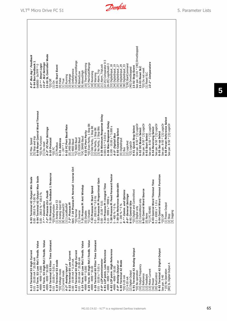
6-13
Ter
min
al 5
3 H
igh
Cu
rren
t0.
01 -
20.
00 m
A *
20.0
0 m
A6-
14 T
erm
. 53
Low
Ref
./Fe
edb.
Val
ue
-499
9 -
4999
* 0
.000
6-15
Ter
m. 5
3 H
igh
Ref
./Fe
edb.
Val
ue
-499
9 -
4999
* 5
0.00
06-
16 T
erm
inal
53
Filt
er T
ime
Con
stan
t0.
01 -
10.
00 s
* 0
.01
s6-
19 T
erm
inal
53
mod
e*[
0] V
olta
ge m
ode
[1]
Curr
ent
mod
e6-
2* A
nalo
g In
put
26-
22 T
erm
inal
60
Low
Cu
rren
t0.
00 -
19.
99 m
A *
0.14
mA
6-23
Ter
min
al 6
0 H
igh
Cu
rren
t0.
01 -
20.
00 m
A *
20.0
0 m
A6-
24 T
erm
. 60
Low
Ref
./Fe
edb.
Val
ue
-499
9 -
4999
* 0
.000
6-25
Ter
m. 6
0 H
igh
Ref
./Fe
edb.
Val
ue
-499
9 -
4999
* 5
0.00
6-26
Ter
min
al 6
0 Fi
lter
Tim
e C
onst
ant
0.01
- 1
0.00
s *
0.0
1 s
6-8*
LCP
pot
enti
omet
er6-
81 L
CP
pot
m. L
ow R
efer
ence
-499
9 -
4999
* 0
.000
6-82
LC
P p
otm
. Hig
h R
efer
ence
-499
9 -
4999
* 5
0.00
6-9*
Ana
log
Out
put
xx6-
90 T
erm
inal
42
Mod
e*[
0] 0
-20
mA
[1]
4-20
mA
[2]
Dig
ital O
utpu
t6-
91 T
erm
inal
42
An
alog
Ou
tpu
t*[
0] N
o op
erat
ion
[10]
Out
put
Freq
uenc
y[1
1] R
efer
ence
[12]
Fee
dbac
k[1
3] M
otor
Cur
rent
[16]
Pow
er[2
0] B
usCo
ntro
l6-
92 T
erm
inal
42
Dig
ital
Ou
tpu
tSe
e pa
r. 5
-40
* [0
] N
o O
pera
tion
[80]
SL
Dig
ital O
utpu
t A
6-93
Ter
min
al 4
2 O
utp
ut
Min
Sca
le0.
00 -
200
.0 %
* 0
.00
%6-
94 T
erm
inal
42
Ou
tpu
t M
ax S
cale
0.00
- 2
00.0
% *
100
.0 %
7-**
Con
trol
lers
7-2*
Pro
cess
Ctr
l. Fe
edb
7-20
Pro
cess
CL
Feed
back
1 R
esou
rce
*[0]
NoF
unct
ion
[1]
Anal
og I
nput
53
[2]
Anal
og in
put
60[8
] Pu
lseI
nput
33[1
1] L
ocal
BusR
ef7-
3* P
roce
ss P
IC
trl.
7-30
Pro
cess
PI
Nor
mal
/ In
vers
e C
trl
*[0]
Nor
mal
[1]
Inve
rse
7-31
Pro
cess
PI
An
ti W
indu
p[0
] D
isab
le*[
1] E
nabl
e7-
32 P
roce
ss P
I St
art
Spee
d0.
0 -
200.
0 H
z *
0.0
Hz
7-33
Pro
cess
PI
Pro
port
ion
al G
ain
0.00
- 1
0.00
* 0
.01
7-34
Pro
cess
PI
Inte
gral
Tim
e0.
10 -
999
9 s
* 99
99 s
7-38
Pro
cess
PI
Feed
For
war
d Fa
ctor
0 -
400
% *
0 %
7-39
On
Ref
eren
ce B
andw
idth
0 -
200
% *
5 %
8-**
Com
m. a
nd O
ptio
ns8-
0* G
ener
al S
etti
ngs
8-01
Con
trol
Sit
e*[
0] D
igita
l and
Con
trol
Wor
d[1
] D
igita
l onl
y[2
] Co
ntro
lWor
d on
ly8-
02 C
ontr
ol W
ord
Sou
rce
[0]
Non
e*[
1] F
C RS
485
8-03
Con
trol
Wor
d Ti
meo
ut
Tim
e0.
1 -
6500
s *
1.0
s8-
04 C
ontr
ol W
ord
Tim
eou
t Fu
nct
ion
*[0]
Off
[1]
Free
ze O
utpu
t[2
] St
op[3
] Jo
ggin
g
[4]
Max
. Spe
ed[5
] St
op a
nd t
rip8-
06 R
eset
Con
trol
Wor
d Ti
meo
ut
*[0]
No
Func
tion
[1]
Do
rese
t8-
3* F
C Po
rt S
etti
ngs
8-30
Pro
toco
l*[
0] F
C[2
] M
odbu
s8-
31 A
ddre
ss1
- 24
7 *
18-
32 F
C P
ort
Bau
d R
ate
[0]
2400
Bau
d[1
] 48
00 B
aud
*[2]
960
0 Ba
ud[3
] 19
200
Baud
*[4]
384
00 B
aud
8-33
FC
Por
t P
arit
y*[
0] E
ven
Parit
y, 1
Sto
p Bi
t[1
] O
dd P
arity
, 1 S
top
Bit
[2]
No
Parit
y, 1
Sto
p Bi
t[3
] N
o Pa
rity,
2 S
top
Bits
8-35
Min
imu
m R
espo
nse
Del
ay0.
001-
0.5
* 0.
010
s8-
36 M
ax R
espo
nse
Del
ay0.
100
- 10
.00
s *
5.00
0 s
8-5*
Dig
ital
/Bus
8-50
Coa
stin
g Se
lect
[0]
Dig
italIn
put
[1]
Bus
[2]
Logi
cAnd
*[3]
Log
icO
r8-
51 Q
uic
k St
op S
elec
tSe
e pa
r. 8
-50
* [3
] Lo
gicO
r8-
52 D
C B
rake
Sel
ect
See
par.
8-5
0 *
[3]
Logi
cOr
8-53
Sta
rt S
elec
tSe
e pa
r. 8
-50
* [3
] Lo
gicO
r8-
54 R
ever
sin
g Se
lect
See
par.
8-5
0 *
[3]
Logi
cOr
8-55
Set
-up
Sele
ctSe
e pa
r. 8
-50
* [3
] Lo
gicO
r8-
56 P
rese
t R
efer
ence
Sel
ect
See
par.
8-5
0 *
[3]
Logi
cOr
8-9*
Bus
Jog
/ F
eedb
ack
8-9
4 B
us
feed
back
10x
8000
- 0
x7FF
F *
013
-**
Smar
t Lo
gic
13-0
* SL
C Se
ttin
gs1
3-0
0 S
L C
ontr
olle
r M
ode
*[0]
Off
[1]
On
13-
01 S
tart
Eve
nt
[0]
Fals
e[1
] Tr
ue[2
] Ru
nnin
g[3
] In
Rang
e[4
] O
nRef
eren
ce[7
] O
utO
fCur
rent
Ran
ge[8
] Be
low
ILow
[9]
Abov
eIH
igh
[16]
The
rmal
War
ning
[17]
Mai
nOut
OfR
ange
[18]
Rev
ersi
ng[1
9] W
arni
ng[2
0] A
larm
_Trip
[21]
Ala
rm_T
ripLo
ck[2
2-25
] Co
mpa
rato
r 0-
3[2
6-29
] Lo
gicR
ule0
-3[3
3] D
igita
lInpu
t_18
[34]
Dig
italIn
put_
19[3
5] D
igita
lInpu
t_27
[36]
Dig
italIn
put_
29[3
8] D
igita
lInpu
t_33
*[39
] St
artC
omm
and
[40]
Driv
eSto
pped
13-
02 S
top
Even
tSe
e pa
r. 1
3-01
* [
40]
Driv
eSto
pped
13-
03 R
eset
SLC
*[0]
Do
not
rese
t[1
] Res
et S
LC13
-1*
Com
para
tors
VLT® Micro Drive FC 51 5. Parameter Lists
MG.02.C4.02 - VLT® is a registered Danfoss trademark 65
5

13
-10
Com
para
tor
Ope
ran
d*[
0] D
isab
led
[1]
Ref
eren
ce[2
] Fe
edba
ck[3
] M
otor
Spee
d[4
] M
otor
Curr
ent
[6]
Mot
orPo
wer
[7]
Mot
orVo
ltage
[8]
DCL
inkV
olta
ge[1
2] A
nalo
gInp
ut53
[13]
Ana
logI
nput
60[1
8] P
ulse
Inpu
t33
[20]
Ala
rmN
umbe
r[3
0] C
ount
erA
[31]
Cou
nter
B1
3-1
1 C
ompa
rato
r O
pera
tor
[0]
Less
Tha
n*[
1] A
ppro
xim
atel
y eq
uals
[2]
Gre
ater
Tha
n1
3-1
2 C
ompa
rato
r V
alu
e-9
999
- 99
99 *
0.0
13-2
* Ti
mer
s13
-20
SL C
ontr
olle
r Ti
mer
0.0
- 36
00 s
* 0
.0 s
13-4
* Lo
gic
Rul
es1
3-4
0 Lo
gic
Ru
le B
oole
an 1
See
par.
13-
01 *
[0]
Fal
se[3
0] -
[32
] SL
Tim
e-ou
t 0-
21
3-4
1 L
ogic
Ru
le O
pera
tor
1*[
0] D
isab
led
[1]
And
[2]
Or
[3]
And
not
[4]
Or
not
[5]
Not
and
[6]
Not
or
[7]
Not
and
not
[8]
Not
or
not
13
-42
Logi
c R
ule
Boo
lean
2Se
e pa
r. 1
3-40
13
-43
Log
ic R
ule
Ope
rato
r 2
See
par.
13-
41 *
[0]
Dis
able
d1
3-4
4 Lo
gic
Ru
le B
oole
an 3
See
par.
13-
4013
-5*
Stat
es1
3-5
1 SL
Con
trol
ler
Even
tSe
e pa
r. 1
3-40
13
-52
SL
Con
trol
ler
Act
ion
*[0]
Dis
able
d
[1]
NoA
ctio
n[2
] Se
lect
Setu
p1[3
] Se
lect
Setu
p2[1
0-17
] Se
lect
Pres
etRe
f0-7
[18]
Sel
ectR
amp1
[19]
Sel
ectR
amp2
[22]
Run
[23]
Run
Rev
erse
[24]
Sto
p[2
5] Q
stop
[26]
DCs
top
[27]
Coa
st[2
8] F
reez
eOut
put
[29]
Sta
rtTi
mer
0[3
0] S
tart
Tim
er1
[31]
Sta
rtTi
mer
2[3
2] S
et D
igita
l Out
put
A Lo
w[3
3] S
et D
igita
l Out
put
B Lo
w[3
8] S
et D
igita
l Out
put
A H
igh
[39]
Set
Dig
ital O
utpu
t B
Hig
h[6
0] R
eset
Coun
terA
[61]
Res
etCo
unte
rB14
-**
Spec
ial F
unct
ions
14-0
* In
vert
er S
wit
chin
g1
4-01
Sw
itch
ing
Freq
uen
cy[0
] 2
kHz
*[1]
4 k
Hz
[2]
8 kH
z[4
] 16
kH
z1
4-03
Ove
rmod
ulat
ion
[0]
Off
*[1]
On
14-1
* M
ains
mon
itor
ing
14-
12
Fu
nct
ion
at
mai
ns im
bala
nce
*[0]
Trip
[1]
War
ning
[2]
Dis
able
d14
-2*
Trip
Res
et1
4-20
Res
et M
ode
*[0]
Man
ual r
eset
[1-9
] Au
toRe
set
1-9
[10]
Aut
oRes
et 1
0[1
1] A
utoR
eset
15
[12]
Aut
oRes
et 2
0[1
3] I
nfin
ite a
uto
rese
t1
4-21
Au
tom
atic
Res
tart
Tim
e0
- 60
0 s
* 10
s
14-
22 O
pera
tion
Mod
e*[
0] N
orm
al O
pera
tion
[2]
Initi
alis
atio
n1
4-2
6 A
ctio
n A
t In
vert
er F
ault
*[0]
Trip
[1]
War
ning
14-4
* En
ergy
Opt
imis
ing
14-
41 A
EO M
inim
um
Mag
net
isat
ion
40 -
75
% *
66
%15
-**
Dri
ve I
nfor
mat
ion
15-0
* O
pera
ting
Dat
a1
5-00
Ope
rati
ng D
ays
15-
01 R
un
ning
Hou
rs1
5-02
kW
h C
oun
ter
15-
03 P
ower
Ups
15-
04 O
ver
Tem
ps1
5-05
Ove
r V
olts
15-
06 R
eset
kW
h C
oun
ter
*[0]
Do
not
rese
t[1
] Res
et c
ount
er1
5-07
Res
et R
un
ning
Hou
rs C
oun
ter
*[0]
Do
not
rese
t[1
] Res
et c
ount
er15
-3*
Faul
t Lo
g1
5-30
Fau
lt L
og:
Erro
r C
ode
15-4
* D
rive
Ide
ntif
icat
ion
15-
40 F
C T
ype
15-
41 P
ower
Sec
tion
15-
42 V
olta
ge1
5-43
Sof
twar
e V
ersi
on1
5-46
Fre
quen
cy C
onve
rter
Ord
er. N
o1
5-48
LC
P I
d N
o1
5-51
Fre
quen
cy C
onve
rter
Ser
ial N
o16
-**
Dat
a R
eado
uts
16-0
* G
ener
al S
tatu
s1
6-00
Con
trol
Wor
d0
- 0X
FFFF
16-
01 R
efer
ence
[U
nit]
-499
9 -
4999
16-
02 R
efer
ence
%-2
00.0
- 2
00.0
%1
6-03
Sta
tus
Wor
d0
- 0X
FFFF
16-
05 M
ain
Act
ual V
alu
e [%
]-2
00.0
- 2
00.0
%1
6-0
9 C
usto
m R
eado
utD
ep. o
n pa
r. 0
-31,
0-3
2 an
d 4-
14
16-1
* M
otor
Sta
tus
16-1
0 P
ower
[kW
]16
-11
Pow
er [
hp]
16-1
2 M
otor
Vol
tage
[V
]16
-13
Freq
uen
cy [
Hz]
16-1
4 M
otor
Cu
rren
t [A
]16
-15
Freq
uen
cy [
%]
16-1
8 M
otor
Th
erm
al [
%]
16-3
* D
rive
Sta
tus
16-3
0 D
C L
ink
Vol
tage
16-3
4 H
eats
ink
Tem
p.16
-35
Inve
rter
Th
erm
al16
-36
Inv.
Nom
. Cu
rren
t16
-37
Inv.
Max
. Cu
rren
t16
-38
SL C
ontr
olle
r St
ate
16-5
* R
ef. /
Fee
db.
16-5
0 Ex
tern
al R
efer
ence
16-5
1 P
uls
e R
efer
ence
16-5
2 Fe
edba
ck [
Un
it]
16-6
* In
puts
/ O
utpu
ts16
-60
Dig
ital
In
put
18,1
9,27
,33
0 -
1111
16-6
1 D
igit
al I
npu
t 29
0 -
116
-62
An
alog
In
put
53 (
volt
)16
-63
An
alog
In
put
53 (
curr
ent)
16-6
4 A
nal
og I
npu
t 60
16-6
5 A
nal
og O
utp
ut
42 [
mA
]16
-68
Pu
lse
Inpu
t [H
z]16
-71
Rel
ay O
utp
ut
[bin
]16
-72
Cou
nte
r A
16-7
3 C
oun
ter
B16
-8*
Fiel
dbus
/ F
C Po
rt16
-86
FC P
ort
REF
10x
8000
- 0
x7FF
FF16
-9*
Dia
gnos
is R
eado
uts
16-9
0 A
larm
Wor
d0
- 0X
FFFF
FFFF
16-9
2 W
arn
ing
Wor
d0
- 0X
FFFF
FFFF
16-9
4 Ex
t. S
tatu
s W
ord
0 -
0XFF
FFFF
FF
5. Parameter Lists VLT® Micro Drive FC 51
66 MG.02.C4.02 - VLT® is a registered Danfoss trademark
5
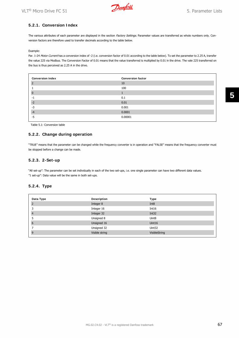
5.2.1. Conversion Index
The various attributes of each parameter are displayed in the section Factory Settings. Parameter values are transferred as whole numbers only. Con-
version factors are therefore used to transfer decimals according to the table below.
Example:
Par. 1-24 Motor Current has a conversion index of -2 (i.e. conversion factor of 0.01 according to the table below). To set the parameter to 2.25 A, transfer
the value 225 via Modbus. The Conversion Factor of 0.01 means that the value transferred is multiplied by 0.01 in the drive. The vale 225 transferred on
the bus is thus perceived as 2.25 A in the drive.
Conversion index Conversion factor
2 10
1 100
0 1
-1 0.1
-2 0.01
-3 0.001
-4 0.0001
-5 0.00001
Table 5.1: Conversion table
5.2.2. Change during operation
“TRUE” means that the parameter can be changed while the frequency converter is in operation and “FALSE” means that the frequency converter must
be stopped before a change can be made.
5.2.3. 2-Set-up
“All set-up”: The parameter can be set individually in each of the two set-ups, i.e. one single parameter can have two different data values.
”1 set-up”: Data value will be the same in both set-ups.
5.2.4. Type
Data Type Description Type
2 Integer 8 Int8
3 Integer 16 Int16
4 Integer 32 Int32
5 Unsigned 8 Uint8
6 Unsigned 16 Uint16
7 Unsigned 32 Uint32
9 Visible string VisibleString
VLT® Micro Drive FC 51 5. Parameter Lists
MG.02.C4.02 - VLT® is a registered Danfoss trademark 67
5

Par
amet
er N
um
ber
Par
amet
er D
escr
ipti
onD
efau
lt V
alue
2 Se
tup
Ch
ange
Du
ring
Ope
rati
onC
onve
rsio
n I
ndex
Type
0 -
03Re
gion
al S
ettin
gs[0
] In
tern
atio
nal
1 se
t-up
FALS
E-
Uin
t80
- 04
Ope
ratin
g St
ate
at P
ower
-up
(Han
d)[1
] Fo
rced
sto
p re
f=ol
dAl
l set
-ups
TRU
E-
Uin
t80
- 10
Activ
e Se
t-up
[1]
Set-
up 1
1 se
t-up
TRU
E-
Uin
t80
- 11
Edit
Set-
up[1
] Se
t-up
11
set-
upTR
UE
-U
int8
0 -
12Li
nk S
etup
s[2
0] L
inke
dAl
l set
-ups
FALS
E-
Uin
t80
- 40
[Han
d on
] Ke
y on
LCP
[1]
Enab
led
All s
et-u
psTR
UE
-U
int8
0 -
41[O
ff /
Res
et]
Key
on L
CP[1
] En
able
All
All s
et-u
psTR
UE
-U
int8
0 -
42[A
uto
on]
Key
on L
CP[1
] En
able
dAl
l set
-ups
TRU
E-
Uin
t80
- 50
LCP
Copy
[0]
No
copy
1 se
t-up
FALS
E-
Uin
t80
- 51
Set-
up C
opy
[0]
No
copy
1 se
t-up
FALS
E-
Uin
t80
- 60
Mai
n M
enu
Pass
wor
d0
1 se
t-up
TRU
E0
Uin
t16
5.2.
5.0-
** O
pera
tion
/Dis
play
5. Parameter Lists VLT® Micro Drive FC 51
68 MG.02.C4.02 - VLT® is a registered Danfoss trademark
5

Par
amet
er N
um
ber
Par
amet
er D
escr
ipti
onD
efau
lt V
alue
2 Se
tup
Ch
ange
Du
ring
Ope
rati
onC
onve
rsio
n I
ndex
Type
1 -
00Co
nfig
urat
ion
Mod
e[0
] Sp
eed
open
loop
All s
et-u
psTR
UE
-U
int8
1 -
01M
otor
Con
trol
Prin
cipl
e[1
] VV
C+Al
l set
-ups
FALS
E-
Uin
t81
- 03
Torq
ue C
hara
cter
istic
s[0
] Co
nsta
nt t
orqu
eAl
l set
-ups
TRU
E-
Uin
t81
- 05
Han
d M
ode
Conf
igur
atio
n[2
] As
mod
e pa
r 1-
00Al
l set
-ups
TRU
E-
Uin
t81
- 20
Mot
or P
ower
Al
l set
-ups
FALS
E-
Uin
t81
- 22
Mot
or V
olta
ge
All s
et-u
psFA
LSE
0U
int1
61
- 23
Mot
or F
requ
ency
Al
l set
-ups
FALS
E0
Uin
t16
1 -
24M
otor
Cur
rent
Al
l set
-ups
FALS
E-2
Uin
t16
1 -
25M
otor
Nom
inal
Spe
ed
All s
et-u
psFA
LSE
0U
int1
61
- 29
Auto
mat
ic M
otor
Tun
ing
(AM
T)[0
] O
ff1
set-
upFA
LSE
-U
int8
1 -
30St
ator
Res
ista
nce
(Rs)
Al
l set
-ups
FALS
E-2
Uin
t16
1 -
33St
ator
Lea
kage
Rea
ctan
ce (
X1)
Al
l set
-ups
FALS
E-2
Uin
t32
1 -
35M
ain
Reac
tanc
e (X
h)
All s
et-u
psFA
LSE
-2U
int3
21
- 50
Mot
or M
agne
tisat
ion
at Z
ero
Spee
d10
0%Al
l set
-ups
TRU
E0
Uin
t16
1 -
52M
in S
peed
Nor
mal
Mag
netis
ing
[Hz]
0 H
zAl
l set
-ups
TRU
E-1
Uin
t16
1 -
55U
/f C
hara
cter
istic
- U
Al
l set
-ups
TRU
E0
Uin
t16
1 -
56U
/f C
hara
cter
istic
- F
Al
l set
-ups
TRU
E0
Uin
t16
1 -
60Lo
w S
peed
Loa
d Co
mpe
nsat
ion
100%
All s
et-u
psTR
UE
0U
int1
61
- 61
Hig
h Sp
eed
Load
Com
pens
atio
n10
0%Al
l set
-ups
TRU
E0
Uin
t16
1 -
62Sl
ip C
ompe
nsat
ion
100%
All s
et-u
psTR
UE
0In
t16
1 -
63Sl
ip C
ompe
nsat
ion
Tim
e Co
nsta
nt0.
1 s
All s
et-u
psTR
UE
-2U
int1
61
- 71
Star
t D
elay
0 s
All s
et-u
psTR
UE
-1U
int8
1 -
72St
art
Func
tion
[2]
Coas
t/de
lay
time
All s
et-u
psTR
UE
-U
int8
1 -
73Fl
ying
Sta
rt[0
] D
isab
led
All s
et-u
psFA
LSE
-U
int8
1 -
80Fu
nctio
n at
Sto
p[0
] Co
ast
All s
et-u
psTR
UE
-U
int8
1 -
82M
in S
peed
for
Fun
ctio
n at
Sto
p [H
z]0
Hz
All s
et-u
psTR
UE
-1U
int1
61
- 90
Mot
or T
herm
al P
rote
ctio
n[0
] N
o pr
otec
tion
All s
et-u
psTR
UE
-U
int8
1 -
93Th
erm
isto
r Res
ourc
e[0
] N
one
All s
et-u
psFA
LSE
-U
int8
5.2
.6.
1-*
* L
oad/
Mot
or
VLT® Micro Drive FC 51 5. Parameter Lists
MG.02.C4.02 - VLT® is a registered Danfoss trademark 69
5

Par
amet
er N
um
ber
Par
amet
er D
escr
ipti
onD
efau
lt V
alue
2 Se
tup
Ch
ange
Du
ring
Ope
rati
onC
onve
rsio
n I
ndex
Type
2 -
00D
C H
old
Curr
ent
50%
All s
et-u
psTR
UE
0U
int1
62
- 01
DC
Brak
e Cu
rren
t50
%Al
l set
-ups
TRU
E0
Uin
t16
2 -
02D
C Br
akin
g Ti
me
10 s
All s
et-u
psTR
UE
-1U
int1
62
- 04
DC
Brak
e Cu
t In
Spe
ed0
Hz
All s
et-u
psTR
UE
-1U
int1
62
- 10
Brak
e Fu
nctio
n[0
] O
ffAl
l set
-ups
TRU
E-
Uin
t82
- 11
Brak
e Re
sist
or (
ohm
)Al
l set
-ups
TRU
E0
Uin
t16
2 -
16AC
Bra
ke, M
ax c
urre
nt10
0%Al
l set
-ups
TRU
E0
Uin
t16
2 -
17O
ver-
volta
ge C
ontr
ol[0
] D
isab
led
All s
et-u
psTR
UE
-U
int8
2 -
20Re
leas
e Br
ake
Curr
ent
0 A
All s
et-u
psTR
UE
-2U
int3
22
- 22
Activ
ate
Brak
e Sp
eed
[Hz]
0 H
zAl
l set
-ups
TRU
E-1
Uin
t16
5.2.
7.2-
** B
rake
s
5. Parameter Lists VLT® Micro Drive FC 51
70 MG.02.C4.02 - VLT® is a registered Danfoss trademark
5

Par
amet
er N
um
ber
Par
amet
er D
escr
ipti
onD
efau
lt V
alue
2 Se
tup
Ch
ange
Du
ring
Ope
rati
onC
onve
rsio
n I
ndex
Type
3 -
00Re
fere
nce
Rang
e[0
] M
in -
Max
All s
et-u
psTR
UE
-U
int8
3 -
02M
inim
um R
efer
ence
0Al
l set
-ups
TRU
E-3
Int3
23
- 03
Max
imum
Ref
eren
ce50
All s
et-u
psTR
UE
-3In
t32
3 -
10Pr
eset
Ref
eren
ce0%
All s
et-u
psTR
UE
-2In
t16
3 -
11Jo
g Sp
eed
[Hz]
5 H
zAl
l set
-ups
TRU
E-1
Uin
t16
3 -
12Ca
tch
up/s
low
Dow
n Va
lue
0%Al
l set
-ups
TRU
E-2
Int1
63
- 14
Pres
et R
elat
ive
Refe
renc
e0%
All s
et-u
psTR
UE
-2In
t16
3 -
15Re
fere
nce
Reso
urce
1[1
] An
alog
in 5
3Al
l set
-ups
TRU
E-
Uin
t83
- 16
Refe
renc
e Re
sour
ce 2
[2]
Anal
og in
60
All s
et-u
psTR
UE
-U
int8
3 -
17Re
fere
nce
Reso
urce
3[1
1] L
ocal
bus
ref
eren
ceAl
l set
-ups
TRU
E-
Uin
t83
- 18
Rela
tive
Scal
ing
Refe
renc
e Re
sour
ce[0
] N
o fu
nctio
nAl
l set
-ups
TRU
E-
Uin
t83
- 40
Ram
p 1
Type
[0]
Line
arAl
l set
-ups
TRU
E-
Uin
t83
- 41
Ram
p 1
Ram
p up
Tim
e3
sAl
l set
-ups
TRU
E-2
Uin
t32
3 -
42Ram
p 1
Ram
p D
own
Tim
e3
sAl
l set
-ups
TRU
E-2
Uin
t32
3 -
50Ra
mp
2 Ty
pe[0
] Li
near
All s
et-u
psTR
UE
-U
int8
3 -
51Ra
mp
2 Ra
mp
up T
ime
3 s
All s
et-u
psTR
UE
-2U
int3
23
- 52
Ram
p 2
Ram
p do
wn
Tim
e3
sAl
l set
-ups
TRU
E-2
Uin
t32
3 -
80Jo
g Ram
p Ti
me
3 s
All s
et-u
psTR
UE
-2U
int3
23
- 81
Qui
ck S
top
Ram
p Ti
me
3 s
1 se
t-up
TRU
E-2
Uin
t32
5.2.
8.3-
** R
efer
ence
/Ram
ps
VLT® Micro Drive FC 51 5. Parameter Lists
MG.02.C4.02 - VLT® is a registered Danfoss trademark 71
5

Par
amet
er N
um
ber
Par
amet
er D
escr
ipti
onD
efau
lt V
alue
2 Se
tup
Ch
ange
Du
ring
Ope
rati
onC
onve
rsio
n I
ndex
Type
4 -
10M
otor
Spe
ed D
irect
ion
[2]
Both
dire
ctio
nsAl
l set
-ups
FALS
E-
Uin
t84
- 12
Mot
or S
peed
Low
Lim
it [H
z]0
Hz
All s
et-u
psFA
LSE
-1U
int1
64
- 14
Mot
or S
peed
Hig
h Li
mit
[Hz]
65 H
zAl
l set
-ups
FALS
E-1
Uin
t16
4 -
16To
rque
Lim
it M
otor
Mod
e15
0%Al
l set
-ups
TRU
E0
Uin
t16
4 -
17To
rque
Lim
it G
ener
ator
Mod
e10
0%Al
l set
-ups
TRU
E0
Uin
t16
4 -
50W
arni
ng C
urre
nt L
ow0
AAl
l set
-ups
TRU
E-2
Uin
t32
4 -
51W
arni
ng C
urre
nt H
igh
26 A
All s
et-u
psTR
UE
-2U
int3
24
- 58
Mis
sing
Mot
or P
hase
Fun
ctio
n[1
] O
nAl
l set
-ups
FALS
E-
Uin
t84
- 61
Bypa
ss S
peed
Fro
m [
Hz]
0 H
zAl
l set
-ups
TRU
E-1
Uin
t16
4 -
63By
pass
Spe
ed T
o [H
z]0
Hz
All s
et-u
psTR
UE
-1U
int1
6
5.2
.9.
4-*
* L
imit
s/W
arn
ings
5. Parameter Lists VLT® Micro Drive FC 51
72 MG.02.C4.02 - VLT® is a registered Danfoss trademark
5

Par
amet
er N
um
ber
Par
amet
er D
escr
ipti
onD
efau
lt V
alue
2 Se
tup
Ch
ange
Du
ring
Ope
rati
onC
onve
rsio
n I
ndex
Type
5 -
10Te
rmin
al 1
8 D
igita
l Inp
ut[8
] St
art
All s
et-u
psTR
UE
-U
int8
5 -
11Te
rmin
al 1
9 D
igita
l Inp
ut[1
0] R
ever
sing
All s
et-u
psTR
UE
-U
int8
5 -
12Te
rmin
al 2
7 D
igita
l Inp
ut[1
] Res
etAl
l set
-ups
TRU
E-
Uin
t85
- 13
Term
inal
29
Dig
ital I
nput
[14]
Jog
All s
et-u
psTR
UE
-U
int8
5 -
15Te
rmin
al 3
3 D
igita
l Inp
ut[1
6] P
rese
t re
f bi
t 0
All s
et-u
psTR
UE
-U
int8
5 -
40Fu
nctio
n Rel
ay[0
] N
o op
erat
ion
All s
et-u
psTR
UE
-U
int8
5 -
55Te
rmin
al 3
3 Lo
w F
requ
ency
20 H
zAl
l set
-ups
TRU
E0
Uin
t16
5 -
56Te
rmin
al 3
3 H
igh
Freq
uenc
y50
00 H
zAl
l set
-ups
TRU
E0
Uin
t16
5 -
57Te
rmin
al 3
3 Lo
w R
ef./
Feed
b. V
alue
0Al
l set
-ups
TRU
E-3
Int3
25
- 58
Term
inal
33
Hig
h Re
f./Fe
edb.
Val
ue50
All s
et-u
psTR
UE
-3In
t32
5.2
.10
.5-
**
Dig
ital
In
/Ou
t
VLT® Micro Drive FC 51 5. Parameter Lists
MG.02.C4.02 - VLT® is a registered Danfoss trademark 73
5

Par
amet
er N
um
ber
Par
amet
er D
escr
ipti
onD
efau
lt V
alue
2 Se
tup
Ch
ange
Du
ring
Ope
rati
onC
onve
rsio
n I
ndex
Type
6 -
00Li
ve Z
ero
Tim
eout
Tim
e10
sAl
l set
-ups
TRU
E0
Uin
t86
- 01
Live
Zer
o Ti
meo
utFu
nctio
n[0
] O
ffAl
l set
-ups
TRU
E-
Uin
t86
- 10
Term
inal
53
Low
Vol
tage
0.07
VAl
l set
-ups
TRU
E-2
Uin
t16
6 -
11Te
rmin
al 5
3 H
igh
Volta
ge10
VAl
l set
-ups
TRU
E-2
Uin
t16
6 -
12Te
rmin
al 5
3 Lo
w C
urre
nt0.
14 m
AAl
l set
-ups
TRU
E-2
Uin
t16
6 -
13Te
rmin
al 5
3 H
igh
Curr
ent
20 m
AAl
l set
-ups
TRU
E-2
Uin
t16
6 -
14Te
rmin
al 5
3 Lo
w R
ef./
Feed
b. V
alue
0Al
l set
-ups
TRU
E-3
Int3
26
- 15
Term
inal
53
Hig
h Re
f./Fe
edb.
Val
ue50
All s
et-u
psTR
UE
-3In
t32
6 -
16Te
rmin
al 5
3 Fi
lter
Tim
e Co
nsta
nt0.
01 s
All s
et-u
psTR
UE
-2U
int1
66
- 19
Term
inal
53
mod
e[0
] Vo
ltage
mod
e1
set-
upTR
UE
-U
int8
6 -
22Te
rmin
al 6
0 Lo
w C
urre
nt0.
14 m
AAl
l set
-ups
TRU
E-2
Uin
t16
6 -
23Te
rmin
al 6
0 H
igh
Curr
ent
20 m
AAl
l set
-ups
TRU
E-2
Uin
t16
6 -
24Te
rmin
al 6
0 Lo
w R
ef./
Feed
b. V
alue
0Al
l set
-ups
TRU
E-3
Int3
26
- 25
Term
inal
60
Hig
h Re
f./Fe
edb.
Val
ue50
All s
et-u
psTR
UE
-3In
t32
6 -
26Te
rmin
al 6
0 Fi
lter
Tim
e Co
nsta
nt0.
01 s
All s
et-u
psTR
UE
-2U
int1
66
- 81
LCP
pote
ntio
met
er L
ow R
ef.
0Al
l set
-ups
TRU
E-3
Int3
26
- 82
LCP
pote
ntio
met
er H
igh
Ref.
50Al
l set
-ups
TRU
E-3
Int3
26
- 90
Term
inal
42
Mod
e[0
] 0-
20 m
AAl
l set
-ups
TRU
E-
Uin
t86
- 91
Term
inal
42
Anal
og O
utpu
t[0
] N
o op
erat
ion
All s
et-u
psTR
UE
-U
int8
6 -
92Te
rmin
al 4
2 D
igita
l Out
put
[0]
No
oper
atio
nAl
l set
-ups
TRU
E-
Uin
t86
- 93
Term
inal
42
Out
put
Min
Sca
le0%
All s
et-u
psTR
UE
-2U
int1
66
- 94
Term
inal
42
Out
put
Max
Sca
le10
0%Al
l set
-ups
TRU
E-2
Uin
t16
5.2
.11
.6-
**
An
alog
In
/Ou
t
5. Parameter Lists VLT® Micro Drive FC 51
74 MG.02.C4.02 - VLT® is a registered Danfoss trademark
5

Par
amet
er N
um
ber
Par
amet
er D
escr
ipti
onD
efau
lt V
alue
2 Se
tup
Ch
ange
Du
ring
Ope
rati
onC
onve
rsio
n I
ndex
Type
7 -
20Pr
oces
s CL
Fee
dbac
k 1
Reso
urce
[0]
No
func
tion
All s
et-u
psTR
UE
-U
int8
7 -
30Pr
oces
s PI
Nor
mal
/ In
vers
e Co
ntro
l[0
] N
orm
alAl
l set
-ups
TRU
E-
Uin
t87
- 31
Proc
ess
PI A
nti W
indu
p[1
] En
able
dAl
l set
-ups
TRU
E-
Uin
t87
- 32
Proc
ess
PI S
tart
Spe
ed0
Hz
All s
et-u
psTR
UE
-1U
int1
67
- 33
Proc
ess
PI P
ropo
rtio
nal G
ain
0.01
All s
et-u
psTR
UE
-2U
int1
67
- 34
Proc
ess
PI I
nteg
ral T
ime
9999
sAl
l set
-ups
TRU
E-2
Uin
t32
7 -
38Pr
oces
s PI
Fee
d Fo
rwar
d Fa
ctor
0%Al
l set
-ups
TRU
E0
Uin
t16
7 -
39O
n Ref
eren
ce B
andw
idth
5%Al
l set
-ups
TRU
E0
Uin
t8
5.2.
12.
7-**
Con
trol
lers
VLT® Micro Drive FC 51 5. Parameter Lists
MG.02.C4.02 - VLT® is a registered Danfoss trademark 75
5

Par
amet
er N
um
ber
Par
amet
er D
escr
ipti
onD
efau
lt V
alue
2 Se
tup
Ch
ange
Du
ring
Ope
rati
onC
onve
rsio
n I
ndex
Type
8 -
01Co
ntro
l Site
[0]
Dig
ital a
nd c
trl.w
ord
All s
et-u
psTR
UE
-U
int8
8 -
02Co
ntro
l Wor
d So
urce
[1]
FC R
S485
All s
et-u
psTR
UE
-U
int8
8 -
03Co
ntro
l Wor
d Ti
meo
ut T
ime
1 s
1 se
t-up
TRU
E-1
Uin
t16
8 -
04Co
ntro
l Wor
d Ti
meo
ut F
unct
ion
[0]
Off
1 se
t-up
TRU
E-
Uin
t88
- 06
Rese
t Co
ntro
l Wor
d Ti
meo
ut[0
] N
o fu
nctio
n1
set-
upTR
UE
-U
int8
8 -
30Pr
otoc
ol[0
] FC
1 se
t-up
TRU
E0
Uin
t88
- 31
Addr
ess
11
set-
upTR
UE
0U
int8
8 -
32FC
Por
t Ba
ud R
ate
[2]
9600
Bau
d1
set-
upTR
UE
-U
int8
8 -
33FC
Por
t Pa
rity
[0]
Even
Par
ity 1
Sto
p Bi
t1
set-
upTR
UE
-U
int8
8 -
35M
inim
um R
espo
nse
Del
ay0.
01 s
1 se
t-up
TRU
E-3
Uin
t16
8 -
36M
ax R
espo
nse
Del
ay5
s1
set-
upTR
UE
-3U
int1
68
- 50
Coas
ting
Sele
ct[3
] Lo
gic
OR
All s
et-u
psTR
UE
-U
int8
8 -
51Q
uick
Sto
p Se
lect
[3]
Logi
c O
RAl
l set
-ups
TRU
E-
Uin
t88
- 52
DC
Brak
e Se
lect
[3]
Logi
c O
RAl
l set
-ups
TRU
E-
Uin
t88
- 53
Star
t Se
lect
[3]
Logi
c O
RAl
l set
-ups
TRU
E-
Uin
t88
- 54
Reve
rsin
g Se
lect
[3]
Logi
c O
RAl
l set
-ups
TRU
E-
Uin
t88
- 55
Set-
up S
elec
t[3
] Lo
gic
OR
All s
et-u
psTR
UE
-U
int8
8 -
56Pr
eset
Ref
eren
ce S
elec
t[3
] Lo
gic
OR
All s
et-u
psTR
UE
-U
int8
8 -
94Bu
s fe
edba
ck 1
0Al
l set
-ups
TRU
E0
Int1
6
5.2
.13
.8-
**
Com
m. a
nd
Opt
ion
s
5. Parameter Lists VLT® Micro Drive FC 51
76 MG.02.C4.02 - VLT® is a registered Danfoss trademark
5

Par
amet
er N
um
ber
Par
amet
er D
escr
ipti
onD
efau
lt V
alue
2 Se
tup
Ch
ange
Du
ring
Ope
rati
onC
onve
rsio
n I
ndex
Type
13 -
00
SL C
ontr
olle
r M
ode
[0]
Off
1 se
t-up
TRU
E-
Uin
t813
- 0
1St
art
Even
t[3
9] S
tart
com
man
d1
set-
upTR
UE
-U
int8
13 -
02
Stop
Eve
nt[4
0] D
rive
stop
ped
1 se
t-up
TRU
E-
Uin
t813
- 0
3Re
set
SLC
[0]
Do
not
rese
t1
set-
upTR
UE
-U
int8
13 -
10
Com
para
tor
Ope
rand
[0]
Dis
able
d1
set-
upTR
UE
-U
int8
13 -
11
Com
para
tor
Ope
rato
r[1
] Ap
prox
Equa
l1
set-
upTR
UE
-U
int8
13 -
12
Com
para
tor
Valu
e0
1 se
t-up
TRU
E-1
Int3
213
- 2
0SL
Con
trol
ler
Tim
er0
s1
set-
upTR
UE
-1U
int3
213
- 4
0Lo
gic
Rule
Boo
lean
1[0
] Fa
lse
1 se
t-up
TRU
E-
Uin
t813
- 4
1Lo
gic
Rule
Ope
rato
r 1
[0]
Dis
able
d1
set-
upTR
UE
-U
int8
13 -
42
Logi
c Ru
le B
oole
an 2
[0]
Fals
e1
set-
upTR
UE
-U
int8
13 -
43
Logi
c Ru
le O
pera
tor
2[0
] D
isab
led
1 se
t-up
TRU
E-
Uin
t813
- 4
4Lo
gic
Rule
Boo
lean
3[0
] Fa
lse
1 se
t-up
TRU
E-
Uin
t813
- 5
1SL
Con
trol
ler
Even
t[0
] Fa
lse
1 se
t-up
TRU
E-
Uin
t813
- 5
2SL
Con
trol
ler
Actio
n[0
] D
isab
led
1 se
t-up
TRU
E-
Uin
t8
5.2
.14
.1
3-*
* S
mar
t Lo
gic
VLT® Micro Drive FC 51 5. Parameter Lists
MG.02.C4.02 - VLT® is a registered Danfoss trademark 77
5

Par
amet
er N
um
ber
Par
amet
er D
escr
ipti
onD
efau
lt V
alue
2 Se
tup
Ch
ange
Du
ring
Ope
rati
onC
onve
rsio
n I
ndex
Type
14 -
01
Switc
hing
Fre
quen
cy[1
] 4.
0 kH
zAl
l set
-ups
TRU
E-
Uin
t814
- 0
3O
verm
odul
atio
n[1
] O
nAl
l set
-ups
FALS
E-
Uin
t814
- 1
2Fu
nctio
n at
Mai
ns I
mba
lanc
e[0
] Tr
ipAl
l set
-ups
TRU
E-
Uin
t814
- 2
0Res
et M
ode
[0]
Man
ual r
eset
All s
et-u
psTR
UE
-U
int8
14 -
21
Auto
mat
ic R
esta
rt T
ime
10 s
All s
et-u
psTR
UE
0U
int1
614
- 2
2O
pera
tion
Mod
e[0
] N
orm
al o
pera
tion
1 se
t-up
TRU
E-
Uin
t814
- 2
6Ac
tion
At I
nver
ter
Faul
t[0
] Tr
ipAl
l set
-ups
TRU
E-
Uin
t814
- 4
1AE
O M
inim
um M
agne
tisat
ion
66 %
All s
et-u
psTR
UE
0U
int8
5.2.
15.
14-*
* S
peci
al F
un
ctio
ns
5. Parameter Lists VLT® Micro Drive FC 51
78 MG.02.C4.02 - VLT® is a registered Danfoss trademark
5

Par
amet
er N
um
ber
Par
amet
er D
escr
ipti
onD
efau
lt V
alue
2 Se
tup
Ch
ange
Du
ring
Ope
rati
onC
onve
rsio
n I
ndex
Type
15 -
00
Ope
ratin
g Ti
me
01
set-
upTR
UE
0U
int3
215
- 0
1Run
ning
Hou
rs0
1 se
t-up
TRU
E0
Uin
t32
15 -
02
kWh
Coun
ter
01
set-
upTR
UE
0U
int3
215
- 0
3Po
wer
Up'
s0
1 se
t-up
TRU
E0
Uin
t32
15 -
04
Ove
r Te
mp'
s0
1 se
t-up
TRU
E0
Uin
t16
15 -
05
Ove
r Vo
lt's
01
set-
upTR
UE
0U
int1
615
- 0
6Re
set
kWh
Coun
ter
[0]
Do
not
rese
t1
set-
upTR
UE
-U
int8
15 -
07
Rese
t Ru
nnin
g H
ours
Cou
nter
[0]
Do
not
rese
t1
set-
upTR
UE
-U
int8
15 -
30
Faul
t Lo
g: E
rror
Cod
e0
1 se
t-up
TRU
E0
Uin
t815
- 4
0FC
Typ
e
1 se
t-up
FALS
E0
Visi
bleS
trin
g15
- 4
1Po
wer
Sec
tion
1
set-
upFA
LSE
0Vi
sibl
eStr
ing
15 -
42
Volta
ge
1 se
t-up
FALS
E0
Visi
bleS
trin
g15
- 4
3SW
ID
Con
trol
Car
d
1 se
t-up
FALS
E0
Visi
bleS
trin
g15
- 4
6Fr
eque
ncy
Conv
erte
r O
rder
ing
No
1
set-
upFA
LSE
0Vi
sibl
eStr
ing
15 -
48
LCP
Id N
o
1 se
t-up
FALS
E0
Visi
bleS
trin
g15
- 5
1Fr
eque
ncy
Conv
erte
r Se
rial N
umbe
r
1 se
t-up
FALS
E0
Visi
bleS
trin
g
5.2.
16.
15-*
* D
rive
In
form
atio
n
VLT® Micro Drive FC 51 5. Parameter Lists
MG.02.C4.02 - VLT® is a registered Danfoss trademark 79
5

Par
amet
er N
um
ber
Par
amet
er D
escr
ipti
onD
efau
lt V
alue
2 Se
tup
Ch
ange
Du
ring
Ope
rati
onC
onve
rsio
n I
ndex
Type
16 -
00
Cont
rol W
ord
01
set-
upTR
UE
0U
int1
616
- 0
1Re
fere
nce
[Uni
t]0
1 se
t-up
TRU
E-3
Int3
216
- 0
2Re
fere
nce
%0
1 se
t-up
TRU
E-1
Int1
616
- 0
3St
atus
Wor
d0
1 se
t-up
TRU
E0
Uin
t16
16 -
05
Mai
n Ac
tual
Val
ue [
%]
01
set-
upTR
UE
-2In
t16
16 -
10
Pow
er [
kW]
01
set-
upTR
UE
-3U
int1
616
- 1
1Po
wer
[hp
]0
1 se
t-up
TRU
E-3
Uin
t16
16 -
12
Mot
or V
olta
ge0
1 se
t-up
TRU
E0
Uin
t16
16 -
13
Freq
uenc
y0
1 se
t-up
TRU
E-1
Uin
t16
16 -
14
Mot
or C
urre
nt0
1 se
t-up
TRU
E-2
Uin
t16
16 -
15
Freq
uenc
y [%
]0
1 se
t-up
TRU
E-1
Uin
t16
16 -
18
Mot
or T
herm
al0
1 se
t-up
TRU
E0
Uin
t816
- 3
0D
C Li
nk V
olta
ge0
1 se
t-up
TRU
E0
Uin
t16
16 -
34
Hea
tsin
k Te
mp.
01
set-
upTR
UE
0U
int8
16 -
35
Inve
rter
The
rmal
01
set-
upTR
UE
0U
int8
16 -
36
Inv.
Nom
. Cur
rent
01
set-
upTR
UE
-2U
int1
616
- 3
7In
v. M
ax. C
urre
nt0
1 se
t-up
TRU
E-2
Uin
t16
16 -
38
SL C
ontr
olle
r St
ate
01
set-
upTR
UE
0U
int8
16 -
50
Exte
rnal
Ref
eren
ce0
1 se
t-up
TRU
E-1
Int1
616
- 5
1Pu
lse
Refe
renc
e0
1 se
t-up
TRU
E-1
Int1
616
- 5
2Fe
edba
ck [
Uni
t]0
1 se
t-up
TRU
E-3
Int3
216
- 6
0D
igita
l inp
ut 1
8,19
,27,
330
1 se
t-up
TRU
E0
Uin
t16
16 -
61
Dig
ital i
nput
29
01
set-
upTR
UE
0U
int8
16 -
62
Anal
og I
nput
53
(V)
01
set-
upTR
UE
-2U
int1
616
- 6
3An
alog
Inp
ut 5
3 (m
A)0
1 se
t-up
TRU
E-2
Uin
t16
16 -
64
Anal
og I
nput
60
01
set-
upTR
UE
-2U
int1
616
- 6
5An
alog
Out
put
42 [
mA]
01
set-
upTR
UE
-2U
int1
616
- 6
8Pu
lse
inpu
t 33
201
set-
upTR
UE
0U
int1
616
- 7
1Re
lay
Out
put
[bin
]0
1 se
t-up
TRU
E0
Uin
t816
- 7
2Co
unte
r A
01
set-
upTR
UE
0In
t16
16 -
73
Coun
ter
B0
1 se
t-up
TRU
E0
Int1
616
- 8
6FC
Por
t RE
F 1
01
set-
upTR
UE
0In
t16
16 -
90
Alar
m W
ord
01
set-
upTR
UE
0U
int3
216
- 9
2W
arni
ng W
ord
01
set-
upTR
UE
0U
int3
216
- 9
4Ex
t. S
tatu
s W
ord
01
set-
upTR
UE
0U
int3
2
5.2
.17
.1
6-*
* D
ata
Rea
dou
ts
5. Parameter Lists VLT® Micro Drive FC 51
80 MG.02.C4.02 - VLT® is a registered Danfoss trademark
5

6. TroubleshootingN
o.D
escr
iptio
nW
arni
ngAl
arm
Trip
Loc
kEr
ror
Caus
e of
Pro
blem
2Li
ve z
ero
erro
rX
X
Si
gnal
on
term
inal
53
or 6
0 is
less
tha
n 50
% o
f va
lue
set
in p
ar. 6
-10,
6-1
2 an
d 6-
22.
4M
ains
pha
se lo
ss1)
XX
X
Mis
sing
pha
se o
n su
pply
sid
e, o
r to
o hi
gh v
olta
ge im
bala
nce.
Che
ck s
uppl
y vo
ltage
.7
DC
over
vol
tage
1)X
X
In
term
edia
te c
ircui
t vo
ltage
exc
eeds
lim
it.8
DC
unde
r vo
ltage
1)X
X
In
term
edia
te c
ircui
t vo
ltage
dro
ps b
elow
“vo
ltage
war
ning
low
” lim
it.9
Inve
rter
ove
rload
edX
X
M
ore
than
100
% lo
ad f
or t
oo lo
ng.
10M
otor
ETR
ove
r te
mpe
ratu
reX
X
M
otor
is t
oo h
ot d
ue t
o m
ore
than
100
% lo
ad f
or t
oo lo
ng.
11M
otor
the
rmis
tor
over
tem
pera
ture
XX
Ther
mis
tor
or t
herm
isto
r co
nnec
tion
is d
isco
nnec
ted.
12To
rque
lim
itX
To
rque
exc
eeds
val
ue s
et in
eith
er p
ar. 4
-16
or 4
-17.
13O
ver
Curr
ent
XX
X
Inve
rter
pea
k cu
rren
t lim
it is
exc
eede
d.14
Eart
h fa
ult
X
X
Dis
char
ge f
rom
out
put
phas
es t
o gr
ound
.16
Shor
t Ci
rcui
t
XX
Sh
ort-
circ
uit
in m
otor
or
on m
otor
ter
min
als.
17Co
ntro
l wor
d tim
eout
XX
No
com
mun
icat
ion
to f
requ
ency
con
vert
er.
25Br
ake
resi
stor
sho
rt-c
ircui
ted
X
X
Brak
e re
sist
or is
sho
rt-c
ircui
ted,
thu
s br
ake
func
tion
is d
isco
nnec
ted.
27Br
ake
chop
per
shor
t-ci
rcui
ted
X
X
Brak
e tr
ansi
stor
is s
hort
-circ
uite
d, t
hus
brak
e fu
nctio
n is
dis
conn
ecte
d.28
Brak
e ch
eck
X
Brak
e re
sist
or is
not
con
nect
ed/w
orki
ng29
Pow
er b
oard
ove
r te
mp
XX
X
Hea
t-si
nk c
ut-o
ut t
empe
ratu
re h
as b
een
reac
hed.
30M
otor
pha
se U
mis
sing
X
X
Mot
or p
hase
U is
mis
sing
. Che
ck t
he p
hase
.31
Mot
or p
hase
V m
issi
ng
XX
M
otor
pha
se V
is m
issi
ng. C
heck
the
pha
se.
32M
otor
pha
se W
mis
sing
X
X
Mot
or p
hase
W is
mis
sing
. Che
ck t
he p
hase
.38
Inte
rnal
fau
lt
XX
Co
ntac
t lo
cal D
anfo
ss s
uppl
ier.
47Co
ntro
l Vol
tage
Fau
ltX
XX
24
V D
C m
ay b
e ov
erlo
aded
.51
AMT
chec
k U
nom a
nd I
nom
X
Wro
ng s
ettin
g fo
r m
otor
vol
tage
and
/or
mot
or c
urre
nt.
52AM
T lo
w I
nom
X
Mot
or c
urre
nt is
too
low
. Che
ck s
ettin
gs.
59Cu
rren
t lim
itX
VL
T ov
erlo
ad.
63M
echa
nica
l Bra
ke L
ow
X
Ac
tual
mot
or c
urre
nt h
as n
ot e
xcee
ded
“rel
ease
bra
ke”
curr
ent w
ithin
“st
art d
elay
” tim
ew
indo
w.
80D
rive
Initi
alis
ed t
o D
efau
lt Va
lue
X
All p
aram
eter
set
tings
are
initi
aliz
ed t
o de
faul
t se
ttin
gs.
84Th
e co
nnec
tion
betw
een
driv
e an
d LC
P is
lost
X
No
com
mun
icat
ion
betw
een
LCP
and
freq
uenc
y co
nver
ter
85Bu
tton
dis
able
d
XSe
e pa
ram
eter
gro
up 0
-4*
LCP
86Co
py f
ail
X
An e
rror
occ
urre
d w
hile
cop
ying
fro
m f
requ
ency
con
vert
er t
o LC
P or
vic
e ve
rsa.
87LC
P da
ta in
valid
X
Occ
urs
whe
n co
pyin
g fr
om L
CP if
the
LCP
con
tain
s er
rone
ous
data
- o
r if
no d
ata
was
uplo
aded
to
the
LCP.
88LC
P da
ta n
ot c
ompa
tible
X
Occ
urs
whe
n co
pyin
g fr
om L
CP if
dat
a ar
e m
oved
bet
wee
n fr
eque
ncy
conv
erte
rs w
ithm
ajor
diff
eren
ces
in s
oftw
are
vers
ions
.89
Para
met
er r
ead
only
X
Occ
urs
whe
n tr
ying
to
writ
e to
a r
ead-
only
par
amet
er.
90Pa
ram
eter
dat
abas
e bu
sy
XLC
P an
d RS
485
conn
ectio
n ar
e tr
ying
to
upda
te p
aram
eter
s si
mul
tane
ousl
y.91
Para
met
er v
alue
is n
ot v
alid
in t
his
mod
e
XO
ccur
s w
hen
tryi
ng t
o w
rite
an il
lega
l val
ue t
o a
para
met
er.
92Pa
ram
eter
val
ue e
xcee
ds t
he m
in/m
ax li
mits
X
Occ
urs
whe
n tr
ying
to
set
a va
lue
outs
ide
the
rang
e.nw
run
Not
Whi
le R
UN
ning
X
Para
met
er c
an o
nly
be c
hang
ed w
hen
the
mot
or is
sto
pped
.Er
r.A
wro
ng p
assw
ord
was
ent
ered
X
Occ
urs
whe
n us
ing
a w
rong
pas
swor
d fo
r ch
angi
ng a
pas
swor
d-pr
otec
ted
para
met
er.
1) T
hese
fau
lts m
ay b
e ca
used
by
mai
ns d
isto
rtio
ns.
Inst
allin
g D
anfo
ss L
ine
Filte
r m
ay r
ectif
y th
is p
robl
em.
Tabl
e 6.
1: C
ode
list
VLT® Micro Drive FC 51 6. Troubleshooting
MG.02.C4.02 - VLT® is a registered Danfoss trademark 81
6

6.1.1. Alarm, Warning and Extended Status Word
Par 1690 Par 1692 Par 1694
Bit Hex Dec AlarmWord WarningWord ExtendedStatusWord
0 1 1 Brake check Ramping
1 2 2 Pwr.card temp Pwr.card temp
2 4 4 Earth Fault Start CW/CCW
3 8 8 Slow down
4 10 16 Ctrl.word TO Ctrl.word TO Catch up
5 20 32 Over Current Over Current
6 40 64 Torque limit
7 80 128 Motor th over Motor th over Output current high
8 100 256 Motor ETR over Motor ETR over Output current low
9 200 512 Inverter overload Inverter overload
10 400 1024 DC under volt DC under volt
11 800 2048 DC over volt DC over volt
12 1000 4096 Short Circuit
13 2000 8192 Braking
14 4000 16384 Mains ph. loss Mains ph. loss
15 8000 32768 "AMT Not OK" OVC active
16 10000 65536 Live zero error Live zero error AC brake
17 20000 131072 Internal fault
18 40000 262144
19 80000 524288 U phase loss
20 100000 1048576 V phase loss
21 200000 2097152 W phase loss
22 400000 4194304
23 800000 8388608 Control Voltage Fault
24 1000000 16777216
25 2000000 33554432 Current limit
26 4000000 67108864 Brake resistor shortcircuit
27 8000000 134217728 Brake IGBT shortcircuit
28 10000000 268435456 MotorPhaseMissing
29 20000000 536870912 Drive initialised
30 40000000 1073741824 Undefined
31 80000000 2147483648 Mech. brake low DatabaseBusy
6. Troubleshooting VLT® Micro Drive FC 51
82 MG.02.C4.02 - VLT® is a registered Danfoss trademark
6

IndexAAbbreviations And Standards 6
Active Set-up 7, 53
Active Set-up 34
Active Set-up 11, 12, 13, 63, 68
BBrake Resistor 23, 35
Brake Resistor 70
Brake Resistor (ohm) 63
Brake Resistor Short-circuited 81
DDc-brake 20, 22, 33, 64
Dc-brake 63
Display 7
Disposal Instruction 4
Drive Identification, 15-4* 58
EEarth Leakage Current 3, 4
Edit Set-up 7
Edit Set-up 11, 12, 13, 63, 68
Electronic Waste 4
GGeneral Warning 6
HHand Mode 64
Hand Mode 40
Hand Mode 11, 15, 35, 69
IIndicator Lights 8
Isolated Mains Source 4
It Mains 4
LLeakage Current 4
Load Compensation 19, 63, 69
Load Compensations 15
MMain Menu 8
Motor Direction 8
Motor Overload Protection 4
Motor Phase 60
Motor Phase 31, 64, 72
Motor Status 59
Motor Temperature 21, 23
Motor Temperature 63
NNavigation Keys 9
Not Changeable During Operation 12
VLT® Micro Drive FC 51 Index
MG.02.C4.02 - VLT® is a registered Danfoss trademark 83

OOperation Keys 9
Over-voltage Control 23, 63, 70
PParameter Number 8
QQuick Menu 8
RRated Magnetizing Current 18
Readout Mode 8
Residual Current Device 4
SSerial Communication 9, 29, 35, 44, 46, 47, 59, 62
Set-up Number 7
Set-up Software 7
Slip Compensation 19, 63, 69
Special Functions 55
Status Menu 8
TThermal Load 18, 60
Thermistor 21
Thermistor 63
Thermistor Resource 69
Trip Reset, 14-2* 55
Type Code String 5
UUnit 8
VValue 8
Index VLT® Micro Drive FC 51
84 MG.02.C4.02 - VLT® is a registered Danfoss trademark