Content Explanation - Oventrop · PDF fileContent 1. Introduction ... this field of the market...
11
Hydronic balance 1 Content 1. Introduction . . . . . . . . . . . . . . . . . . . . . . . . . . . . . . . . .3 1.1 General description . . . . . . . . . . . . . . . . . . . . . . . . . .3 1.2 History of hydronic balance . . . . . . . . . . . . . . . . . . . .3 2. Technical description . . . . . . . . . . . . . . . . . . . . . . . . . .4 2.1 Hydronic regulation at the radiator . . . . . . . . . . . . . .4 2.2 Hydronic balance of the pipework . . . . . . . . . . . . . . .4 2.3 Methods of calculation . . . . . . . . . . . . . . . . . . . . . . .5 3. VOB . . . . . . . . . . . . . . . . . . . . . . . . . . . . . . . . . . . . . . . .7 4. Potential of energy saving . . . . . . . . . . . . . . . . . . . . .8 4.1 General information . . . . . . . . . . . . . . . . . . . . . . . . .8 4.2 Calculation of the potential of energy saving . . . . . . .8 4.3 Energy saving in exemplary projects . . . . . . . . . . . . . .9 5. How to carry out hydronic balance . . . . . . . . . . . . . .10 6. Conclusion . . . . . . . . . . . . . . . . . . . . . . . . . . . . . . . . . .10 Imprint Published by: Zentralverband Sanitär Heizung Klima Rathausallee 6, D-53757 St. Augustin Telephone (0 22 41) 2 90 56 - 58 Telefax (0 22 41) 2 13 51 oder 2 11 31 E-Mail [email protected] Internet http://www.wasserwaermeluft.de Reprint, even parts, only with approval of the publisher Explanation This professional information explains that the hydronic balance of heating and cooling systems is necessary and that it comes up to the great demands on the tech- niques for energy saving. This brochure describes the hydronic balance and shows the potentials for energy sav- ing. It is addressed to the spe- cialised trade and shall be of help for the exploitation of this field of the market at the end user. This professional information was written in cooperation with: Consulting engineer Dr.-Ing. Hans-Joachim Koch, Biele- feld, Germany Oventrop GmbH & Co. KG, D-Olsberg, Germany
Transcript of Content Explanation - Oventrop · PDF fileContent 1. Introduction ... this field of the market...
Hydronic balance
1
Content
1. Introduction . . . . . . . . . . . . . . . . . . . . . . . . . . . . . . . . .3
1.1 General description . . . . . . . . . . . . . . . . . . . . . . . . . .3
1.2 History of hydronic balance . . . . . . . . . . . . . . . . . . . .3
2. Technical description . . . . . . . . . . . . . . . . . . . . . . . . . .4
2.1 Hydronic regulation at the radiator . . . . . . . . . . . . . .4
2.2 Hydronic balance of the pipework . . . . . . . . . . . . . . .4
2.3 Methods of calculation . . . . . . . . . . . . . . . . . . . . . . .5
3. VOB . . . . . . . . . . . . . . . . . . . . . . . . . . . . . . . . . . . . . . . .7
4. Potential of energy saving . . . . . . . . . . . . . . . . . . . . .8
4.1 General information . . . . . . . . . . . . . . . . . . . . . . . . .8
4.2 Calculation of the potential of energy saving . . . . . . .8
4.3 Energy saving in exemplary projects . . . . . . . . . . . . . .9
5. How to carry out hydronic balance . . . . . . . . . . . . . .10
6. Conclusion . . . . . . . . . . . . . . . . . . . . . . . . . . . . . . . . . .10
Imprint
Published by: Zentralverband Sanitär Heizung KlimaRathausallee 6, D-53757 St. AugustinTelephone (0 22 41) 2 90 56 - 58Telefax (0 22 41) 2 13 51 oder 2 11 31E-Mail [email protected] http://www.wasserwaermeluft.de
Reprint, even parts, only with approval of the publisher
ExplanationThis professional informationexplains that the hydronicbalance of heating andcooling systems is necessaryand that it comes up to thegreat demands on the tech-niques for energy saving.
This brochure describes thehydronic balance and showsthe potentials for energy sav-ing. It is addressed to the spe-cialised trade and shall be ofhelp for the exploitation ofthis field of the market at theend user.
This professional informationwas written in cooperationwith:
Consulting engineer Dr.-Ing.Hans-Joachim Koch, Biele-feld, Germany
Oventrop GmbH & Co. KG,D-Olsberg, Germany

Hydronic balance
3
1. Introduction
1.1 General description
The hydronic balance of thepipework in buildings is not only aneconomic and ecological necessitybut it is also required according tothe DIN standards and decrees (e.g.VOB/C – DIN 18380).
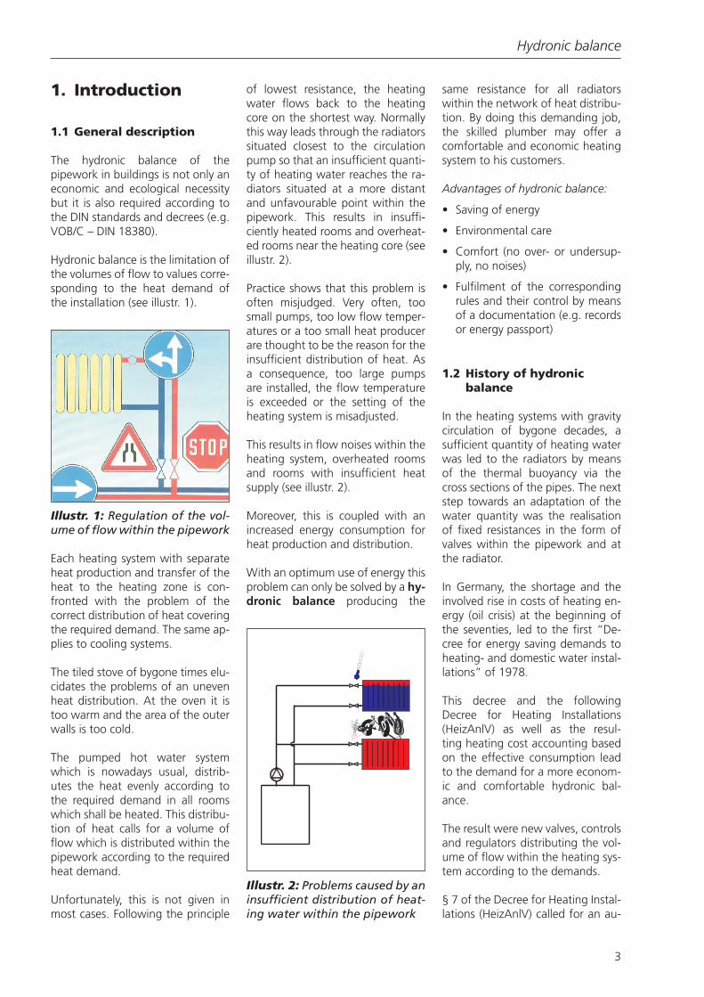
Hydronic balance is the limitation ofthe volumes of flow to values corre-sponding to the heat demand ofthe installation (see illustr. 1).
Each heating system with separateheat production and transfer of theheat to the heating zone is con-fronted with the problem of thecorrect distribution of heat coveringthe required demand. The same ap-plies to cooling systems.
The tiled stove of bygone times elu-cidates the problems of an unevenheat distribution. At the oven it istoo warm and the area of the outerwalls is too cold.
The pumped hot water systemwhich is nowadays usual, distrib-utes the heat evenly according tothe required demand in all roomswhich shall be heated. This distribu-tion of heat calls for a volume offlow which is distributed within thepipework according to the requiredheat demand.
Unfortunately, this is not given inmost cases. Following the principle
of lowest resistance, the heatingwater flows back to the heatingcore on the shortest way. Normallythis way leads through the radiatorssituated closest to the circulationpump so that an insufficient quanti-ty of heating water reaches the ra-diators situated at a more distantand unfavourable point within thepipework. This results in insuffi-ciently heated rooms and overheat-ed rooms near the heating core (seeillustr. 2).
Practice shows that this problem isoften misjudged. Very often, toosmall pumps, too low flow temper-atures or a too small heat producerare thought to be the reason for theinsufficient distribution of heat. Asa consequence, too large pumpsare installed, the flow temperatureis exceeded or the setting of theheating system is misadjusted.
This results in flow noises within theheating system, overheated roomsand rooms with insufficient heatsupply (see illustr. 2).
Moreover, this is coupled with anincreased energy consumption forheat production and distribution.
With an optimum use of energy thisproblem can only be solved by a hy-dronic balance producing the
same resistance for all radiatorswithin the network of heat distribu-tion. By doing this demanding job,the skilled plumber may offer acomfortable and economic heatingsystem to his customers.
Advantages of hydronic balance:
• Saving of energy
• Environmental care
• Comfort (no over- or undersup-ply, no noises)
• Fulfilment of the correspondingrules and their control by meansof a documentation (e.g. recordsor energy passport)
1.2 History of hydronicbalance
In the heating systems with gravitycirculation of bygone decades, asufficient quantity of heating waterwas led to the radiators by meansof the thermal buoyancy via thecross sections of the pipes. The nextstep towards an adaptation of thewater quantity was the realisationof fixed resistances in the form ofvalves within the pipework and atthe radiator.
In Germany, the shortage and theinvolved rise in costs of heating en-ergy (oil crisis) at the beginning ofthe seventies, led to the first “De-cree for energy saving demands toheating- and domestic water instal-lations” of 1978.
This decree and the followingDecree for Heating Installations(HeizAnlV) as well as the resul-ting heating cost accounting basedon the effective consumption leadto the demand for a more econom-ic and comfortable hydronic bal-ance.
The result were new valves, controlsand regulators distributing the vol-ume of flow within the heating sys-tem according to the demands.
§ 7 of the Decree for Heating Instal-lations (HeizAnlV) called for an au-
Illustr. 1: Regulation of the vol-ume of flow within the pipework
Illustr. 2: Problems caused by aninsufficient distribution of heat-ing water within the pipework
Hydronic balance
4
tomatic individual room tempera-ture control of these heating sys-tems and this demand is fulfilled bythe installation of thermostatic radi-ator valves.
The progressive computer techniqueaccompanied this development witheven better, more comfortable anduseful software programmes for thecalculation of the pipework.
2. Technical description
each individual case which valve orregulator has to be installed fromthe economical point of view.
➢ Double regulating andcommissioning valves
Double regulating and commission-ing valves are installed in hot watercentral heating systems and coolingsystems and permit an adaptationof the volumes of flow between thevarious circuits of the system (see illustr. 4).
The regulation of the double regu-lating and commissioning valvesmay be carried out with the systemin operation which guarantees real-istic flow values during full demand
2.1 Hydronic regulationat the radiator
The hydronic balance of a waterdistribution system depends on anumber of facts which may not becalculated easily. This is why an ex-act balance of the system may onlybe carried out by means of a calcu-lation of the heat demand and ofthe pipework.
The following steps of calculationare necessary for the hydronic bal-ance:
• calculation of the heat demandfor each individual room
• calculation of the heating sur-faces and their volume of flowtaking the resulting, effective re-turn temperatures into consider-ation
• calculation of the pipework withthe calculated volumes of flow ofthe radiators
An important step is the regulationwhen bringing the installation into
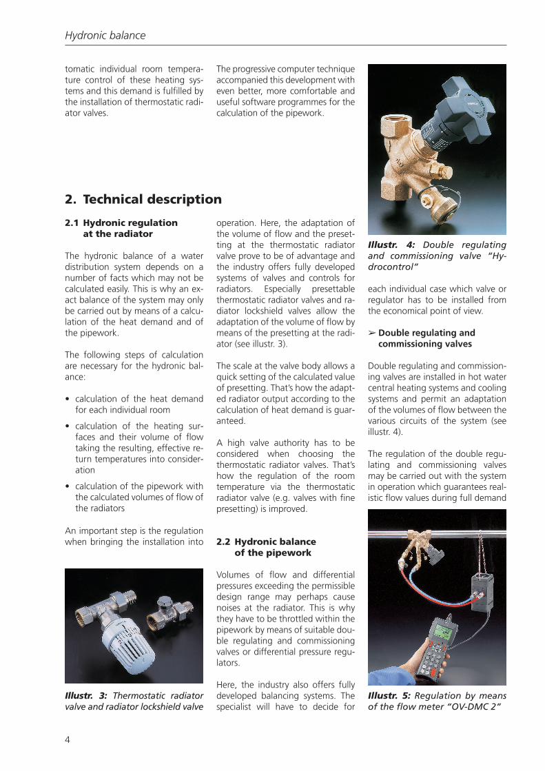
operation. Here, the adaptation ofthe volume of flow and the preset-ting at the thermostatic radiatorvalve prove to be of advantage andthe industry offers fully developedsystems of valves and controls forradiators. Especially presettablethermostatic radiator valves and ra-diator lockshield valves allow theadaptation of the volume of flow bymeans of the presetting at the radi-ator (see illustr. 3).
The scale at the valve body allows aquick setting of the calculated valueof presetting. That’s how the adapt-ed radiator output according to thecalculation of heat demand is guar-anteed.
A high valve authority has to beconsidered when choosing thethermostatic radiator valves. That’show the regulation of the roomtemperature via the thermostaticradiator valve (e.g. valves with finepresetting) is improved.
2.2 Hydronic balanceof the pipework
Volumes of flow and differentialpressures exceeding the permissibledesign range may perhaps causenoises at the radiator. This is whythey have to be throttled within thepipework by means of suitable dou-ble regulating and commissioningvalves or differential pressure regu-lators.
Here, the industry also offers fullydeveloped balancing systems. Thespecialist will have to decide for
Illustr. 3: Thermostatic radiatorvalve and radiator lockshield valve
Illustr. 4: Double regulatingand commissioning valve “Hy-drocontrol”
Illustr. 5: Regulation by meansof the flow meter “OV-DMC 2”

Hydronic balance
5
periods or within the design range(see illustr. 5).
➢ Differential pressureregulators
Differential pressure regulators areproportional regulators workingwithout auxiliary energy. They arerequired for a constant regulationof the necessary nominal value.
Differential pressure regulators aredesigned for use in heating or cool-ing systems to maintain a constantdifferential pressure within a neces-sary proportional band (see illustr.6).
➢ Flow regulators
Flow regulators are installed as pro-portional regulators without auxil-iary energy for a constant regulationof the set flow rate. They are de-signed for use in heating or coolingsystems to maintain a constant flowwithin a necessary proportionalband (see illustr. 7).
2.3 Methods of calucation
According to the VOB/C-DIN 18380standard, the heat demand has to
be taken into consideration whencalculating the heating water circu-lating within the pipework. Corre-sponding software programmesmake this job easier. Pipe dimen-sions and presetting values are au-tomatically assigned to the valvesand controls within the pipeworkand at the radiators.
Moreover, the software pro-grammes with CAD-support also al-low the illustration of the pipeworkand all other components of the in-stallation. All valves and controls aswell as presetting values are as-signed correspondingly and are de-fined in a general drawing.
Should a pipework calculation beimpossible, e.g. in case of refurbish-ment, the calculation may be basedon approximate values.
With an estimated differential pres-sure of 200 mbar at the valve, “ac-ceptable” set values are obtained insmall installations with a pumphead of about 200 mbar and inlarge installations with a decen-tralised regulation of differentialpressure to approximately 100mbar per pipe.
With a known heat demand anda fixed temperature difference, the
volume of flow of the individual ra-diator and the presetting at thevalve are obtained.
Example 1:
Q = 1200 W∆ϑ = 20 Kc = 1.163 W*h/(l*K)
1) Formula signs and units see below
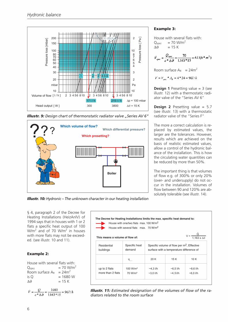
With the volume of flow of 52 l/hand the differential pressure of 100mbar, a presetting value of 2 can betaken from the design chart (see il-lustr. 8 and 9).
If the heat demand of the room isunknown, it is possible to calculatethe heat demand following § 4,paragraph 2 of the Decree for Heat-ing Installations (HeizAnlV) underthe given fringe conditions.
Illustr. 7: Flow regulator “Hy-dromat Q”
Formula sign Designation Unit
Q Heat demand W
Qspez Specific heat demand W/m2
V.
Volume of flow l/h
∆ϑ Differenz K
c Convertedspec. heatcapacity W*h/(l*K)
Illustr. 6: Differential pressureregulator “Hydromat DP”
Illustr. 8: Thermostatic radiatorvalve “Series AV 6”
Hydronic balance
6
§ 4, paragraph 2 of the Decree forHeating Installations (HeizAnlV) of1994 says that in houses with 1 or 2flats a specific heat output of 100W/m2 and of 70 W/m2 in houseswith more flats may not be exceed-ed. (see illustr. 10 and 11).
Example 2:
House with several flats with:Qspez = 70 W/m2
Room surface AR = 24m2
is Q = 1680 W∆ϑ = 15 K
Example 3:
House with several flats with:Qspez = 70 W/m2
∆ϑ = 15 K
Room surface AR = 24m2
Design 1 Presetting value = 3 (seeillustr. 12) with a thermostatic radi-ator valve of the “Series AV 6”
Design 2 Presetting value = 5.7(see illustr. 13) with a thermostaticradiator valve of the “Series F”
The more a correct calculation is re-placed by estimated values, thelarger are the tolerances. However,results which are achieved on thebasis of realistic estimated values,allow a control of the hydronic bal-ance of the installation. This is howthe circulating water quantities canbe reduced by more than 50%.
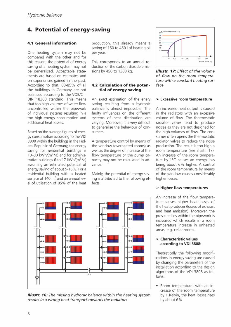
The important thing is that volumesof flow e.g. of 300% or only 20%(over- and undersupply) do not oc-cur in the installation. Volumes offlow between 90 and 120% are ab-solutely tolerable (see illustr. 14).
Pre
ssur
e lo
ss [m
bar]
Volume of flow
Head output
Pre
ssur
e lo
ss
Illustr. 9: Design chart of thermonstatic radiator valve „Series AV 6“
Which volume of flow?Which differential pressure?
Which presetting?
Boiler
Illustr. 10: Hydronic – The unknown character in our heating installation
The Decree for Heating Installations limits the max. specific heat demand to:
House with one/two flats max. 100 W/m2
House with several flats max. 70 W/m2
This means a volume of flow of:
Residential
buildings
Specific heat
demand
Specific volume of flow per m2, Effective
surface with a temperature difference of
up to 2 flats
more than 2 flats
Illustr. 11: Estimated designation of the volumes of flow of the ra-diators related to the room surface
Hydronic balance
7
3. VOB
According to the VOB/C – DIN18380 standard, a hydronic balancehas to be carried out in each heat-ing installation (see illustr. 15).
Moreover, the VOB/C – DIN 18380standard, paragraph 3.5.1 says thatthe hydronic balance has to be car-ried out in such a way that a suffi-cient quantity of heating water ac-cording to their heat demand issupplied to all heat consumers. Thisis also valid after a room tempera-ture setback or when the operationof the heating system was inter-rupted.
The VOB is, however, very often notrespected. This means that manyheating systems do not fulfil thevalid rules and do not correspond tothe latest developments in technol-ogy.
Presetting 1up to 17 l/h
Presetting 2up to 55 l/h
Presetting 3up to 100 l/h
Presetting 4up to 145 l/h
Presetting 5up to 175 l/h
Presetting 6up to 215 l/h
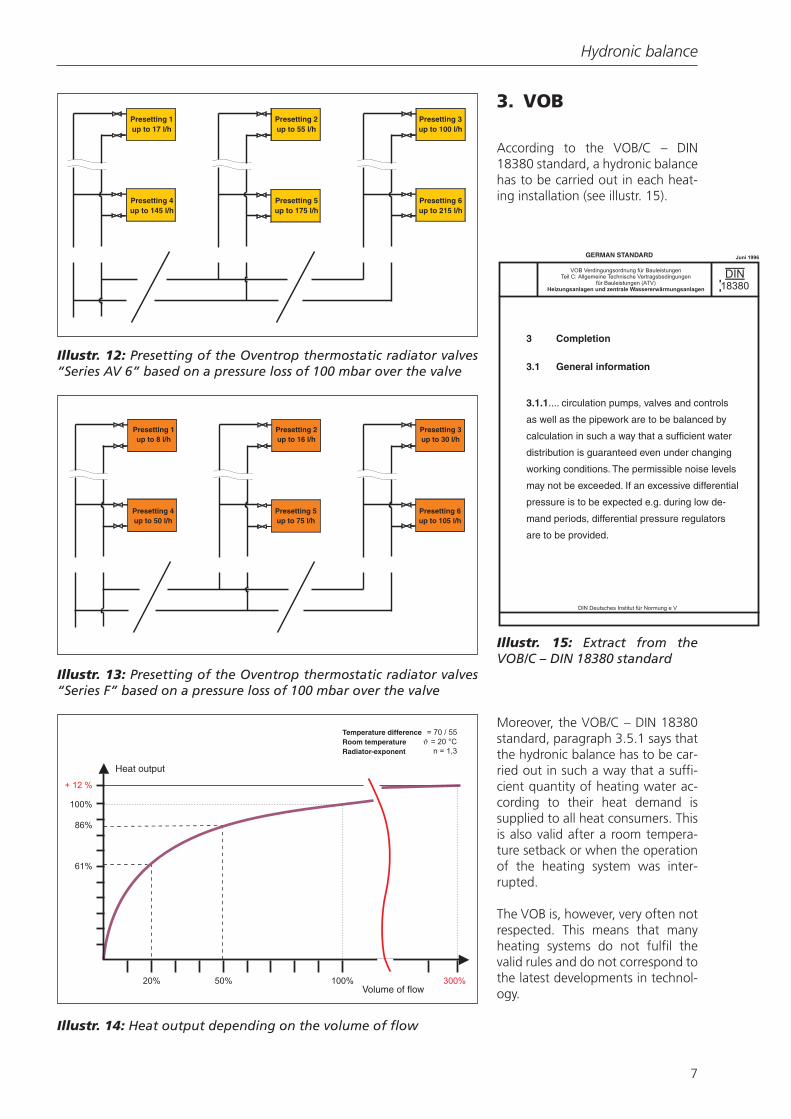
Illustr. 12: Presetting of the Oventrop thermostatic radiator valves“Series AV 6” based on a pressure loss of 100 mbar over the valve
Presetting 1up to 8 l/h
Presetting 2up to 16 l/h
Presetting 3up to 30 l/h
Presetting 4up to 50 l/h
Presetting 5up to 75 l/h
Presetting 6up to 105 l/h
Illustr. 13: Presetting of the Oventrop thermostatic radiator valves“Series F” based on a pressure loss of 100 mbar over the valve
Heat output
Volume of flow
Temperature differenceRoom temperatureRadiator-exponent
Illustr. 14: Heat output depending on the volume of flow
3.1.1.... circulation pumps, valves and controls
as well as the pipework are to be balanced by
calculation in such a way that a sufficient water
distribution is guaranteed even under changing
working conditions. The permissible noise levels
may not be exceeded. If an excessive differential
pressure is to be expected e.g. during low de-
mand periods, differential pressure regulators
are to be provided.
GERMAN STANDARD
3 Completion
3.1 General information
Illustr. 15: Extract from theVOB/C – DIN 18380 standard
Hydronic balance
8
4. Potential of energy-saving
4.1 General information
One heating system may not becompared with the other and forthis reason, the potential of energysaving of a heating system may notbe generalised. Acceptable state-ments are based on estimates andon experiences gained in the past.According to that, 80-85% of allthe buildings in Germany are notbalanced according to the VOB/C –DIN 18380 standard. This meansthat too high volumes of water flowuncontrolled within the pipeworkof individual systems resulting in atoo high energy consumption andadditional heat losses.
Based on the average figures of ener-gy consumption according to the VDI3808 within the buildings in the Fed-eral Republic of Germany, the energysaving for residential buildings is10–30 kWh/(m2*a) and for adminis-trative buildings 6 to 17 kWh/(m2*a)assuming an estimated potential ofenergy saving of about 5-15%. For aresidential building with a heatedsurface of 140 m2 and an annual lev-el of utilisation of 85% of the heat
production, this already means asaving of 150 to 450 l of heating oilper year.
This corresponds to an annual re-duction of the carbon dioxide emis-sions by 450 to 1300 kg.
4.2 Calculation of the poten-tial of energy saving
An exact estimation of the enerysaving resulting from a hydronicbalance is almost impossible. Thefaulty influences on the differentsystems of heat distribution arevarying. Moreover, it is very difficultto generalise the behaviour of con-sumers.
A temperature control by means ofthe window (overheated rooms) aswell as the degree of increase of theflow temperature or the pump ca-pacity may not be calculated in ad-vance.
Mainly, the potential of energy sav-ing is attributed to the following ef-fects:
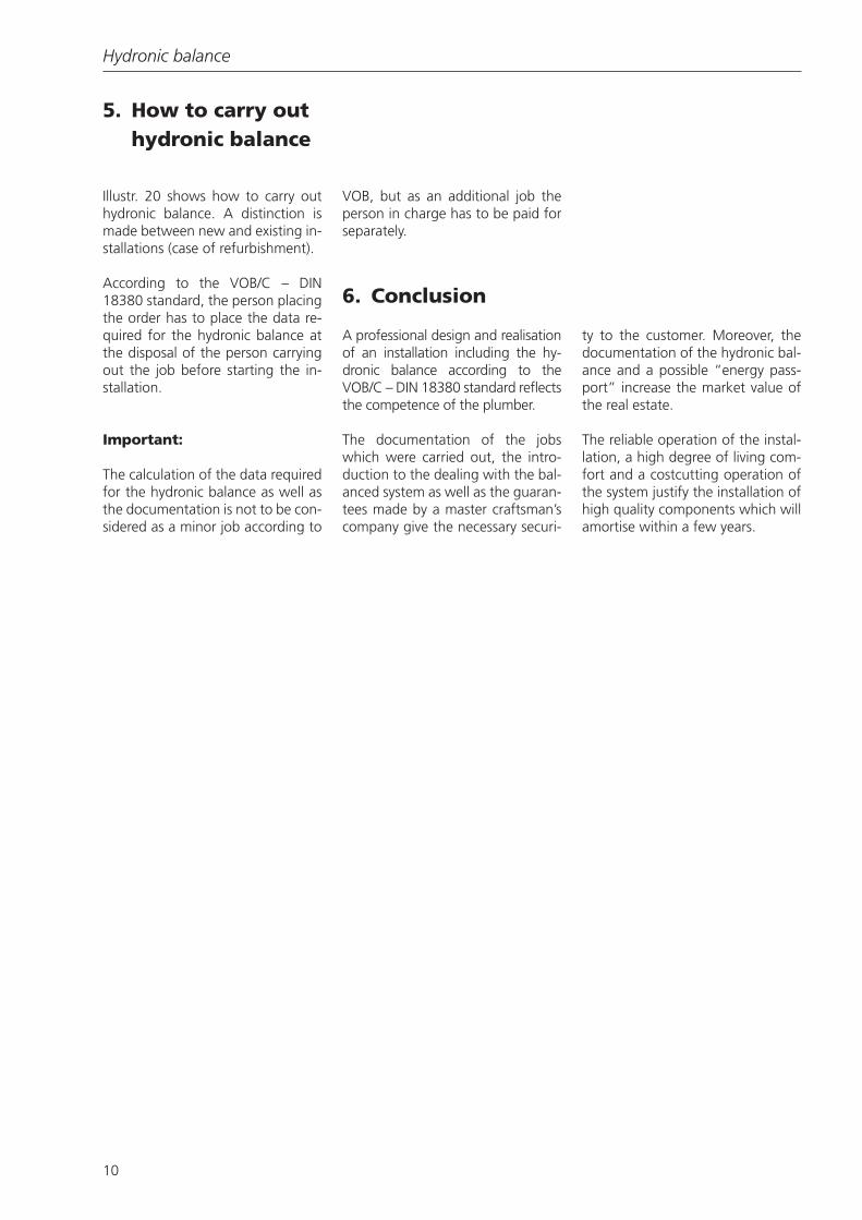
➢ Excessive room temperature
An increased heat output is causedin the radiators with an excessivevolume of flow. The thermostaticradiator valves tend to producenoises as they are not designed forthe high volumes of flow. The con-sumer often opens the thermostaticradiator valves to reduce the noiseproduction. The result is too high aroom temperature (see illustr. 17).An increase of the room tempera-ture by 1°C causes an energy lossbeing about 6% higher. A controlof the room temperature by meansof the window causes considerablyhigher losses.
➢ Higher flow temperatures
An increase of the flow tempera-ture causes higher heat losses ofthe heat producer (losses of exhaustand heat emission). Moreover, thepressure loss within the pipework isincreased which results in a roomtemperature increase in unheatedareas, e.g. cellar rooms.
➢ Characteristic values according to VDI 3808:
Theoretically the following modifi-cations in energy saving are causedby changing the parameters of theinstallation according to the designalgorithms of the VDI 3808 as fol-lows:
• Room temperature: with an in-crease of the room temperatureby 1 Kelvin, the heat losses risesby about 6%
Illustr. 16: The missing hydronic balance within the heating systemresults in a wrong heat transport towards the radiators
Room temperature [ ° C]
Volume of flow [%]
Illustr. 17: Effect of the volumeof flow on the room tempera-ture with a constant heating sur-face

Hydronic balance
9
• Loss of exhaust:Increase of the exhaust tempera-ture by 20 Kelvin = increase ofthe exhaust loss by 1.2%
• Loss of heat emission:Increase of loss of heat emissionby 0.25% when increasing theboiler temperature by 10 Kelvin
• Loss in distribution:Increase of loss in distribution by1.5% when increasing the aver-age heating water temperaturewithin the pipework by 10 Kelvin
• Window control:Heat loss depending on behav-iour of consumer
With the described loss factors, anenergy saving of about 5-15% re-lated to the complete heat produc-ing- and heat distributing installa-tion can be achieved by carrying outthe hydronic balance of the system.
➢ Increased volume of flow ofthe circulation pump
An increased volume of flow of hotwater (for the supposed eliminationof the faults) within an unbalancednetwork of distribution leads to an
increased energy consumption ofthe circulation pumps. With a calcu-lated nominal pressure loss and ahalving of the volume of flow, theconsumption of driving energy canbe reduced by 10 to 20%.
Note:
A hydronic balance is not always re-lated to additional costs. As therunning costs of the installation willbe reduced by the hydronic bal-ance, the necessary investments willsoon amortise. Moreover, the car-bon dioxide emission will be re-duced.
An investigation (study: reductionof the carbon dioxide emission byrefurbishing the pumps by Prof. Dr.-Ing. Bach, University of Stuttgart)revealed that the power consump-tion of circulation pumps in Ger-many is three times higher thannecessary. Cautious predictions be-yond the study even show that ahydronic balance of the heating sys-tem during refurbishment works incombination with an electronicallyregulated circulation pump will helpto reduce the energy consumptionof the pump by about 40% (see il-lustr. 19).
4.3 Energy savings inexemplary projects
Example: Potential of energy savingwith a regulated pump
A pump capacity of about 50 Wattis required for the heat distributionin a house with 2 flats with a heatdemand of 20 kW. If a 90 Wattpump is installed, the power con-sumption is 40 Watt too high. With6000 working hours per year, thisamounts to 240 kWh, which meansadditional costs of about 31,– eper year with a price of 0,13 e/kWh.
With the 20 million circulationpumps which are installed in Ger-many an potential of energy savingof
• Electric driving energy:2.2 billion kWh/a
• Emissions of carbon dioxide:1.32 million t/a
can be considered to be realistic.Two thirds fall to houses with 1 to 2flats.
Illustr. 18: A correct heat transport towards the radiators dueto a hydronic balance guarantees a troublefree operation of the sys-tem
unregulated circulation pump regulated circulation pump
Price
Power c
onsumptio
n
Total c
osts
Emissions o
f carbon diox
ide
Illustr. 19: Possibility of energysaving by using electronicallyregulated circulation pumps;Source: Grundfos GmbH, Wahl-stedt
Hydronic balance
10
5. How to carry outhydronic balance
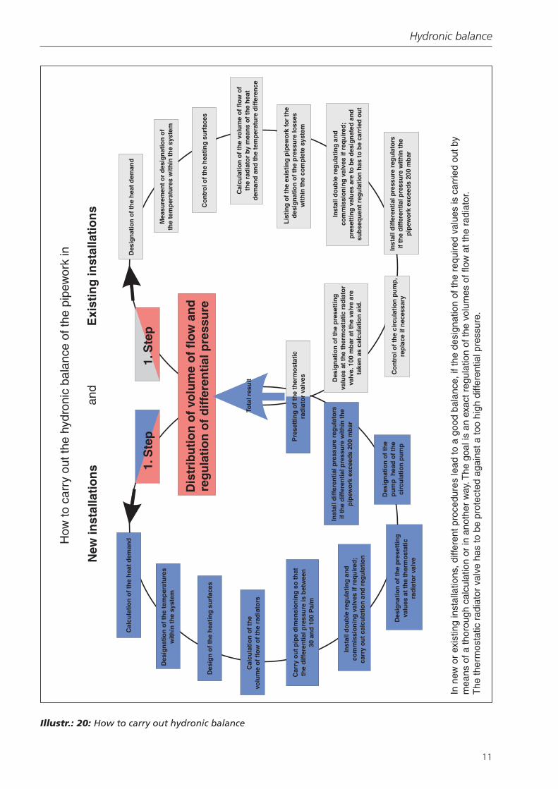
Illustr. 20 shows how to carry outhydronic balance. A distinction ismade between new and existing in-stallations (case of refurbishment).
According to the VOB/C – DIN18380 standard, the person placingthe order has to place the data re-quired for the hydronic balance atthe disposal of the person carryingout the job before starting the in-stallation.
Important:
The calculation of the data requiredfor the hydronic balance as well asthe documentation is not to be con-sidered as a minor job according to
VOB, but as an additional job theperson in charge has to be paid forseparately.
6. Conclusion
A professional design and realisationof an installation including the hy-dronic balance according to theVOB/C – DIN 18380 standard reflectsthe competence of the plumber.
The documentation of the jobswhich were carried out, the intro-duction to the dealing with the bal-anced system as well as the guaran-tees made by a master craftsman’scompany give the necessary securi-
ty to the customer. Moreover, thedocumentation of the hydronic bal-ance and a possible “energy pass-port” increase the market value ofthe real estate.
The reliable operation of the instal-lation, a high degree of living com-fort and a costcutting operation ofthe system justify the installation ofhigh quality components which willamortise within a few years.
Hydronic balance
11
How
to c
arry
out
the
hydr
onic
bal
ance
of t
he p
ipew
ork
in
and
New
inst
alla
tio
ns 1.
Ste
p1.
Ste
p
Dis
trib
uti
on
of
volu
me
of
flo
w a
nd
reg
ula
tio
n o
f d
iffe
ren
tial
pre
ssu
re
Exi
stin
g in
stal
lati
on
s
Cal
cula
tio
n o
f th
e h
eat
dem
and
Des
ign
atio
n o
f th
e te
mp
erat
ure
sw
ith
in t
he
syst
em
Des
ign
of
the
hea
tin
g s
urf
aces
Cal
cula
tio
n o
f th
evo
lum
e o
f fl
ow
of
the
rad
iato
rs
Car
ry o
ut
pip
e d
imen
sio
nin
g s
o t
hat
the
dif
fere
nti
al p
ress
ure
is b
etw
een
30 a
nd
100
Pa/
m
Inst
all d
ou
ble
reg
ula
tin
g a
nd
com
mis
sio
nin
g v
alve
s if
req
uir
ed;
carr
y o
ut
calc
ula
tio
n a
nd
reg
ula
tio
n
Des
ign
atio
n o
f th
e p
rese
ttin
gva
lues
at
the
ther
mo
stat
icra
dia
tor
valv
e
Des
ign
atio
n o
f th
ep
um
p h
ead
of
the
circ
ula
tio
n p
um
p
Inst
all d
iffe
ren
tial
pre
ssu
re r
egu
lato
rsif
th
e d
iffe
ren
tial
pre
ssu
re w
ith
in t
he
pip
ewo
rk e
xcee
ds
200
mb
ar
Pre
sett
ing
of
the
ther
mo
stat
icra
dia
tor
valv
es
Tota
l res
ult
Des
ign
atio
n o
f th
e h
eat
dem
and
Mea
sure
men
t o
r d
esig
nat
ion
of
the
tem
per
atu
res
wit
hin
th
e sy
stem
Co
ntr
ol o
f th
e h
eati
ng
su
rfac
es
Cal
cula
tio
n o
f th
e vo
lum
e o
f fl
ow
of
the
rad
iato
r by
mea
ns
of
the
hea
td
eman
d a
nd
th
e te
mp
erat
ure
dif
fere
nce
Lis
tin
g o
f th
e ex
isti
ng
pip
ewo
rk fo
r th
ed
esig
nat
ion
of
the
pre
ssu
re lo
sses
wit
hin
th
e co
mp
lete
sys
tem
Inst
all d
ou
ble
reg
ula
tin
g a
nd
com
mis
sio
nin
g v
alve
s if
req
uir
ed;
pre
sett
ing
val
ues
are
to
be
des
ign
ated
an
dsu
bse
qu
ent
reg
ula
tio
n h
as t
o b
e ca
rrie
d o
ut
Inst
all d
iffe
ren
tial
pre
ssu
re r
egu
lato
rsif
th
e d
iffe
ren
tial
pre
ssu
re w
ith
in t
he
pip
ewo
rk e
xcee
ds
200
mb
ar
Co
ntr
ol o
f th
e ci
rcu
lati
on
pu
mp
,re
pla
ce if
nec
essa
ry
Des
ign
atio
n o
f th
e p
rese
ttin
gva
lues
at
the
ther
mo
stat
ic r
adia
tor
valv
e. 1
00 m
bar
at
the
valv
e ar
eta
ken
as
calc
ula
tio
n a
id.
In n
ew o
r ex
istin
g in
stal
latio
ns, d
iffer
ent p
roce
dure
s le
ad to
a g
ood
bala
nce,
if th
e de
sign
atio
n of
the
requ
ired
valu
es is
car
ried
out b
ym
eans
of a
thor
ough
cal
cula
tion
or in
ano
ther
way
. The
goa
l is
an e
xact
reg
ulat
ion
of th
e vo
lum
es o
f flo
w a
t the
rad
iato
r.T
he th
erm
osta
tic r
adia
tor
valv
e ha
s to
be
prot
ecte
d ag
ains
t a to
o hi
gh d
iffer
entia
l pre
ssur
e.
Illustr.: 20: How to carry out hydronic balance