Contactor Box - MK Products...washing, depending on the combustible’s solubility), followed by...
20
Owner’s Manual Product: MK200 Contactor Box Manual: 091-0253 Serial: N/A Voltage Rating: 115 VAC Revision: April 2007 Rev B Model Number: N/A Contactor Box
Transcript of Contactor Box - MK Products...washing, depending on the combustible’s solubility), followed by...

Owner’s ManualProduct: MK200
Contactor BoxManual: 091-0253Serial: N/AVoltage Rating: 115 VACRevision: April 2007 Rev BModel Number: N/A
Contactor Box

Table of Contents
Safety Guidelines
Installation ................................................................................ Section ATechnical Specifications ........................................................................................ 9General Description .............................................................................................. 9Power Leads ......................................................................................................... 9Control Leads........................................................................................................ 9
Operation ..................................................................................Section BHookup to Cobramatic .......................................................................................... 9
Diagrams/Parts List .................................................................Section CMechanical .......................................................................................................... 14Electrical ............................................................................................................. 16
Safety Warnings
Warranty

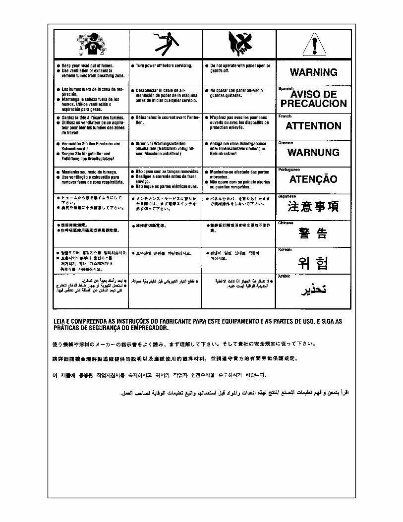
SAFETY CONSIDERATIONSELECTRIC ARC WELDING EQUIPMENT
CAUTION : READ BEFORE ATTEMPTING INSTALLATION, OPERATION OR MAINTENANCE OF THIS EQUIPMENT
1-1 INTRODUCTIONThis equipment is intended for ultimate application by commercial/industrial users and for operation by persons trained and experienced in the use and maintenance of welding equipment. Operation should not be undertaken without adequate training in the use of such equipment. Training is available from many public and private schools or similar facilities.Safe practices in the installation, opera-tion and maintenance of this equipment requires proper training in the art, a careful study of the information provided with the equipment, and the use of common sense. Rules for safe use are generally provided by suppliers of welding power sources, compressed gas suppliers, and electrode suppliers. Careful compliance with these rules will promote safe use of this equipment.The following Safety Rules cover some of the more generally found situations. READ THEM CAREFULLY. In case of any doubt, obtain qualified help before proceeding.
1-2 GENERAL PRECAUTIONSA. Burn PreventionELECTRIC ARC WELDING PRODUCES HIGH INTENSITY HEAT AND ULTRA-VIOLET RADIANT ENERGY WHICH MAY CAUSE SERIOUS AND PER-MANENT EYE DAMAGE AND WHICH MAY DAMAGE ANY EXPOSED SKIN AREAS.Wear helmet with safety goggles or glasses with side shields underneath, appropriate filter lenses or plates (pro-tected by clear cover glass). This is a must for welding or cutting (and chipping) to protect the eyes from radiant energy and flying metal. Replace cover glass when broken, pitted, or spattered.Medical first aid and eye treatment. First aid facilities and a qualified first aid person should be available for each shift unless medical facilities are close by for immediate treatment of flash burns of the eyes and skin burns.Wear protective clothing - leather (or asbestos) gauntlet gloves, hat, and high safety-toe shoes. Button shirt collar and pocket flaps, and wear cuffless trousers to avoid entry of sparks and slag.Avoid oily or greasy clothing. A spark may ignite them.Flammable hair preparations should not be used by persons intending to weld or cut.
Hot metal such as electrode stubs and work pieces should never be handled without gloves.Ear plugs should be worn when working on overhead or in a confined space. A hard hat should be worn when others work overhead.
B. Toxic Fume PreventionWARNING: The use of this product may result in exposure to chemicals known to the State of California to cause cancer and birth defects or other reproductive harm.Adequate ventilation. Severe discomfort, illness or death can result from fumes, vapors, heat, or oxygen enrichment or depletion that welding (or cutting) may produce. Prevent them with adequate ventilation. NEVER ventilate with oxygen.Lead-, cadmium-, zinc-, mercury-, beryl-lium-bearing and similar materials, when welded or cut, may produce harmful con-centrations of toxic fumes. Adequate local exhaust ventilation must be used, or each person in the area, as well as the operator, must wear an air-supplied respirator. For beryllium, both must be used.Metals coated with or containing materials that emit toxic fumes should not be heated unless coating is removed form the work surface, the area is well ventilated, or the operator wears an air-supplied respirator.Work in a confined space only while it is being ventilated and, if necessary, while wearing an air-supplied respirator.Gas leaks in a confined space should be avoided. Leaked gas in large quantities can change oxygen concentration dangerously. Do not bring gas cylinders into a confined space.Leaving confined space, shut OFF gas supply at source to prevent possible accu-mulation of gases in the space if down-stream valves have been accidentally opened or left open. Check to be sure that the space is safe before reentering it.Vapors from chlorinated solvents can be decomposed by the heat of the arc (or flame) to form PHOSGENE, a highly toxic gas, and other lung and eye irritating prod-ucts. The ultraviolet (radiant) energy of the arc can also decompose trichloroethylene and perchloroethylene vapors to form phosgene. DO NOT WELD or cut where solvent vapors can be drawn into the welding or cutting atmosphere or where the radiant energy can penetrate to atmo-spheres containing even minute amounts of trichloroethylene or perchloroethylene.
C. Fire and Explosion PreventionCauses of fire and explosion are: com-
bustibles reached by the arc, flame, flying sparks, hot slag, or heated mate-rial, misuse of compressed gases and cylinders, and short circuits.BE AWARE THAT flying sparks or falling slag can pass through cracks, along pipes, through windows or doors, and through wall or floor openings, out of sight of the goggled operator. Sparks can fly many feet.To prevent fires and explosion:Keep equipment clean and operable, free of oil, grease, and (in electrical parts) of metallic particles that can cause short circuits.If combustibles are in area, do NOT weld or cut. Move the work if practicable, to an area free of combustibles. Avoid paint spray rooms, dip tanks, storage areas, ventilators. If the work cannot be moved, move combustibles at least 35 feet away, out of reach of sparks and heat; or protect against ignition with suitable and snug-fitting, fire-resistant covers or shields.Walls touching combustibles on opposite sides should not be welded on (or cut). Walls, ceilings, and floor near work should be protected by heat-resistant covers or shields.Fire watcher must be standing by with suitable fire extinguishing equipment during and for some time after welding or cutting if:1. Appreciable combustibles (including building construction) are within 35 feet.2. Appreciable combustibles are further than 35 feet, but can be ignited by sparks.3. Openings (concealed or visible) in floors or walls within 35 feet may expose combustibles to sparks.4. Combustibles adjacent to walls, ceil-ings, roofs, or metal partitions can be ignited by radiant or conducted heat.Hot work permit should be obtained before operation to ensure supervisor’s approval that adequate precautions have been taken.After work is done, check that area is free of sparks, glowing embers, and flames.An empty container that held combus-tibles, or that can produce flammable or toxic vapors when heated, must never be welded on or cut, unless container has first been cleaned in accordance with industry standards.This includes: a thorough steam or caustic cleaning (or a solvent of water

washing, depending on the combustible’s solubility), followed by purging and inert-ing with nitrogen or carbon dioxide, and using protective equipment.Water-filling just below working level may substitute for inerting.A container with unknown contents should be cleaned (see paragraph above). Do NOT depend on sense of smell or sight to determine if it is safe to weld or cut.Hollow castings or containers must be vented before welding or cutting. They can explode.Explosive atmospheres. NEVER weld or cut where the air may contain flammable dust, gas, or liquid vapors (such as gasoline).
D. Compressed Gas EquipmentThe safe handling of compressed gas equipment is detailed in numerous industry publications. The following general rules cover many of the most common situations.1. Pressure RegulatorsRegulator relief valve is designed to protect only the regulator from over-pressure; it is not intended to protect any downstream equipment. Provide such protection with one or more relief devices.Never connect a regulator to a cylinder containing gas other than that for which the regulator was designed.Remove faulty regulator from service immediately for repair (first close cylinder valve). The following symptoms indicate a faulty regulator:Leaks - if gas leaks externally.Excessive Creep - if delivery pressure continues to rise with downstream valve closed.Faulty Gauge - if gauge pointer does not move off stop pin when pressurized, nor returns to stop pin after pressure release.Repair. Do NOT attempt repair. Send faulty regulators for repair to manufac-turer’s designated repair center, where special techniques and tools are used by trained personnel.2. CylindersCylinders must be handled carefully to prevent leaks and damage to their walls, valves, or safety devices:Avoid electrical circuit contact with cylinders including third rails, electrical wires, or welding circuits. They can produced short circuit arcs that may lead to a serious accident. (See 1-3C)ICC or DOT marking must be on each cylinder. It is an assurance of safety when the cylinder is properly handled.Identifying gas content. Use only cylin-ders with name of gas marked on them; do not rely on color to identify gas content. Notify supplier if unmarked. NEVER DEFACE or alter name, number,
or other markings on a cylinder. It is illegal and hazardous.Empties: Keep valves closed, replace caps securely; mark MT; keep them separate from FULLS, and return promptly.Prohibited use. Never use a cylinder or its contents for other than its intended use, NEVER as a support or roller.Locate or secure cylinders so they cannot be knocked over.Passageways and work areas. Keep cylin-ders clear of areas where they may be stuck.Transporting cylinders. With a crane, use a secure support such as a platform or cradle. Do NOT lift cylinders off the ground by their valves or caps, or by chains, slings, or magnets.Do NOT expose cylinders to excessive heat, sparks, slag, and flame, etc. that may cause rupture. Do not allow contents to exceed 55 degrees C (130 degrees F.) Cool with water spray where such exposure exists.Protect cylinders, particularly valves from bumps, falls, falling objects, and weather. Replace caps securely when moving cyl-inders.Stuck valve. Do NOT use a hammer or wrench to open a cylinder valve that cannot be opened by hand. Notify your supplier.Mixing gases. NEVER try to mix any gases in a cylinder.NEVER refill any cylinder.Cylinder fittings should never be modified or exchanged.3. HoseProhibited use. Never use hose other than that designed for the specified gas. A general hose identification rule is: red for fuel gas, green for oxygen, and black for inert gases.Use ferrules or clamps designed for the hose (not ordinary wire or other substitute) as a binding to connect hoses to fittings.No copper tubing splices. Use only stan-dard brass fittings to splice hose.Avoid long runs to prevent kinks and abuse. Suspend hose off ground to keep it from being run over, stepped on, or otherwise damaged.Coil excess hose to prevent kinks and tangles.Protect hose from damage by sharp edges, and by sparks, slag, and open flame.Examine hose regularly for leaks, wear, and loose connections. Immerse pressured hose in water; bubbles indicate leaksRepair leaky or worn hose by cutting area out and splicing. Do NOT use tape.4. Proper ConnectionsClean cylinder valve outlet of impurities that may clog orifices and damage seats before connecting regulator. Except for hydrogen, crack valve momentarily, pointing outlet away from people and sources of ignition. Wipe with a clean, lintless cloth.
Match regulator to cylinder. Before connecting, check that the regulator label and cylinder marking agree, and that the regulator inlet and cylinder outlet match. NEVER Connect a regulator designed for a particular gas or gases to a cylinder containing any other gas.Tighten connections. When assembling threaded connections, clean and smooth seats where necessary. Tighten. If connection leaks, disassemble, clean, and retighten, using properly fitting wrench.Adapters. Use a CGA adapter (available from your supplier) between cylinder and regulator, if one is required. Use two wrenches to tighten adapter marked RIGHT and LEFT HAND threads.Regulator outlet (or hose) connections may be identified by right hand threads for oxygen and left hand threads (with grooved hex on nut or shank) for fuel gas.5. Pressurizing Steps:Drain regulator of residual gas through suitable vent before opening cylinder (or manifold valve) by turning adjusting screw in (clockwise). Draining prevents excessive compression heat at high pressure seat by allowing seat to open on pressurization. Leave adjusting screw engaged slightly on single-stage regulators.Stand to side of regulator while opening cylinder valve.Open cylinder valve slowly so that regula-tor pressure increases slowly. When gauge is pressurized (gauge reaches regulator maximum) leave cylinder valve in following position: for oxygen and inert gases, open fully to seal stem against possible leak; for fuel gas, open to less than one turn to permit quick emergency shut-off.Use pressure charts (available from your supplier) for safe and efficient recommended pressure settings on regulators.Check for leaks on first pressurization and regularly thereafter. Brush with soap solution. Bubbles indicate leaks. Clean off soapy water after test; dried soap is combustible.
E. User ResponsibilitiesFollow all Safety Rules.Remove leaky or defective equipment from service immediately for repair. Read and follow user manual instructions.
F. Leaving Equipment Unat-tendedClose gas supply at source and drain gas.
G. Rope Staging-SupportRope staging-support should not be used for welding or cutting operation; rope may burn.
1-3 ARC WELDINGComply with precautions in 1-1, 1-2,

and this section. Arc Welding, properly done, is a safe process, but a careless operator invites trouble. The equipment carries high currents at significant volt-ages. The arc is very bright and hot. Sparks fly, fumes rise, ultraviolet and infrared energy radiates, weldments are hot, and compressed gases may be used. The wise operator avoids unnecessary risks and protects himself and others from accidents.
A. Burn ProtectionComply with precautions in 1-2.The welding arc is intense and visibly bright. Its radiation can damage eyes, penetrate lightweight clothing, reflect from light-colored surfaces, and burn the skin and eyes. Skin burns resemble acute sunburn; those from gas-shielded arcs are more severe and painful. DON’T GET BURNED; COMPLY WITH PRE-CAUTIONS.1. Protective ClothingWear long-sleeve clothing in addition to gloves, hat, and shoes. As necessary, use additional protective clothing such as leather jacket or sleeves, flameproof apron, and fire-resistant leggings. Avoid outer garments of untreated cotton.Bare skin protection. Wear dark, sub-stantial clothing. Button collar to protect chest and neck, and button pockets to prevent entry of sparks.2. Eye and Head ProtectionProtect eyes from exposure to arc. Eyes may be damaged by radiant energy when exposed to the electric arc, even when not looking in the direction of the arc. Never look at an electric arc without protection.Welding helmet or shield containing a filter plate shade no. 12 or denser must be used when welding. Place over face before striking arc.Protect filter plate with a clear cover plate.Cracked or broken helmet or shield should NOT be worn; radiation can be passed through to cause burns.Cracked, broken, or loose filter plates must be replaced IMMEDIATELY. Replace clear cover plate when broken, pitted, or spattered.Flash goggles with side shields MUST be worn under the helmet to give some protection to the eyes should the helmet not be lowered over the face before an arc is struck. Looking at an arc momentarily with unprotected eyes (particularly a high intensity gas-shielded arc) can cause a retinal burn that may leave a permanent dark area in the field of vision.3. Protection of Nearby PersonnelEnclose the welding area. For production welding, a separate room or enclosed bay is best. In open areas, surround the operation with low-reflective, noncom-bustible screens or panels. Allow for free
air circulation, particularly at floor level.Viewing the weld. Provide face shields for all persons who will be looking directly at the weld.Others working in area. See that all persons are wearing flash goggles.Before starting to weld, make sure that screen flaps or bay doors are closed.
B. Toxic Fume PreventionComply with precautions in 1-2B.Generator engine exhaust must be vented to the outside air. Carbon monoxide can kill.C. Fire and Explosion PreventionComply with precautions in 1-2C.Equipment’s rated capacity. Do not overload arc welding equipment. It may overheat cables and cause a fire.Loose cable connections may overheat or flash and cause afire.Never strike an arc on a cylinder or other pressure vessel. It creates a brittle area that can cause a violent rupture or lead to such a rupture later under rough handling.
D. Compressed Gas EquipmentComply with precautions in 1-2D.E. Shock PreventionExposed electrically hot conductors or other bare metal in the welding circuit, or in ungrounded, electrically-HOTequipment can fatally shock a person whose body becomes a conductor. DO NOT STAND, SIT, LIE, LEAN ON, OR TOUCH a wet surface when welding without suitable protection.To protect against shock:Keep body and clothing dry. Never work in damp area without adequate insulation against electrical shock. Stay on a dry duckboard, or rubber mat when dampness or sweat cannot be avoided. Sweat, sea water, or moisture between body and an electrically HOT part - or grounded metal - reduces the body surface electri-cal resistance, enabling dangerous and possibly lethal currents to flow through the body.1. Grounding the EquipmentWhen installing, connect the frames of each unit such as welding power source, control, work table, and water circulator to the building ground. Conductors must be adequate to carry ground currents safely. Equipment made electrically HOT by stray currents may shock, possibly fatally. Do NOT GROUND to electrical conduit, or to a pipe carrying ANY gas or a flammable liquid such as oil or fuel.Three-phase connection. Check phase requirement of equipment before installing. If only three-phase power is available, connect single-phase equipment to only two wires of the three-phase line. Do NOT connect the equipment ground lead to the third (live) wire, or the equipment will become electrically HOT - a dangerous condition that can shock, possibly fatally.
Before welding, check ground for continu-ity. Be sure conductors are touching bare metal of equipment frames at con-nections.If a line cord with a ground lead is provided with the equipment for connec-tion to a switch box, connect the ground lead to the grounded switch box. If a three-prong plug is added for connection to a grounded mating receptacle, the ground lead must be connected to the ground prong only. If the line cord comes with a three-prong plug, connect to a grounded mating receptacle. Never remove the ground prong from a plug, or use a plug with a broken ground prong.2. ConnectorsFully insulated lock-type connectors should be used to join welding cable lengths.3. CablesFrequently inspect cables for wear, cracks, and damage. IMMEDIATELY REPLACE those with excessively worn or damaged insulation to avoid possibly lethal shock from bared cable. Cables with damaged areas may be taped to give resistance equivalent to original cable.Keep cable dry, free of oil and grease, and protected from hot metal and sparks.4. Terminals and Other Exposed PartsTerminals and other exposed parts of electrical units should have insulating covers secured before operation.5. Electrode WireElectrode wire becomes electrically HOT when the power switch of gas metal-arc welding equipment is ON and welding gun trigger is pressed. Keep hands and body clear of wire and other HOT parts.6. Safety DevicesSafety devices such as interlocks and circuit breakers should not be discon-nected or shunted out.Before installation, inspection, or service of equipment, shut OFF all power, and remove line fuses (or lock or red-tag switches) to prevent accidental turning ON of power. Disconnect all cables from welding power source, and pull all 115 volts line-cord plugs.Do not open power circuit or change polarity while welding. If, in an emer-gency, it must be disconnected, guard against shock burns or flash from switch arcing.Leaving equipment unattended. Always shut OFF, and disconnect all power to equipment.Power disconnect switch must be avail-able near the welding power source.

Thank You For selecting a quality product. We want you to takepride in operating this product...as much pride as wehave in bringing the product to you!
When this equipment is shipped, title passes to the purchaser upon receipt by thecarrier. Consequently, claims for material damaged in shipment must be made by thepurchaser against the transportation company at the time the shipment is received.
Please record your equipment identification information below for future reference. Thisinformation can be found on your machine nameplate.
Model Name & Number _____________________
Code & Serial Number _____________________
Date of Purchase _____________________
Whenever you request replacements parts for, or information on this equipment alwayssupply the information you have recorded above.
Please Examine Carton and Equipment For Damage Immediately
Read this Owner’s Manual completely before attempting to use this equipment. Save this manualand keep it handy for quick reference. Pay particular attention to the safety instructions wehave provided for your protection.

THIS PAGE INTENTIONALLY BLANK

MK200 Owner’s Manual - Page 9
Section A Installation
Specifications Duty Cycle 60% at 250 amps Weight 7 lbs. 4 oz. Shipping Weight 9 lbs.
GeneralThe Contactor Box is designed to be mechanically fastened to the top of the WC-1 and includes a handle, making it easy to move the system to any desired location. To mount the Contactor Box to the WC-1, remove the clips from the side of the Contactor Box and insert the lips of the securing clips into the louvers of the WC-1.
Power LeadsThe positive lead from the welding power source is connected to the “+ weld power” side and the Prince power lug is connected to the “Torch” side.
Control LeadsThe cable from the Contactor Box connects to the 120 VAC contactor control terminal inside the WC-1. Remove the lid from the WC-1 and insert the cable from the Contactor Box through the strain relief. Connect the white wire to J5 terminal #3, the black wire to J5 terminal #4, and the green wire to ground post. See diagram on next page.
Section B Operation
Hookup to CobramaticWhen using with the Cobramatic wire feeder system connect the 115VAC contactor leads directly to the terminal strip inside the MK200, connecting the white wire to terminal #1 and the black wire to terminal #2, make sure to switch the contacts to 115VAC output on the wire feeder.
NOTE: When using the Contactor Box with equipment other than the WC-1, attach 115VAC contactor NEUTRAL wire to Terminal 1 and the 115VAC contactor HOT wire to
Terminal 2 of the Contactor Box.
4 1/2"
9 3/4"
7 1/4"
Size 9 3/4"L x 4 1/2"H x 7 1/4"W

MK200 Owner’s Manual - Page 10
CONNECTIONS TO WC-1 CONTROL BOX
CAUTION : When working with voltages present in this Product and others, always observe warning and caution signs. Service must only be performed by qualified service personnel.

MK200 Owner’s Manual - Page 11
CONNECTIONS TO COBRAMATIC FEEDER
CAUTION : When working with voltages present in this Product and others, always observe warning and caution signs. Service must only be performed by qualified service personnel.

MK200 Owner’s Manual - Page 12
CONNECTIONS TO COBRAMATIC II FEEDER
CAUTION : When working with voltages present in this Product and others, always observe warning and caution signs. Service must only be performed by qualified service personnel.

MK200 Owner’s Manual - Page 13
Section F Appendices
MK 200 Contactor Box Diagrams / Parts ListExploded Parts View ..................................................14Electrical Schematic ..................................................16

MK200 Owner’s Manual - Page 14
MK200 Secondary Contactor001-3066

MK200 Owner’s Manual - Page 15
MK 200 Secondary ContactorNo. Qty. Part No. Description
1 1 435-1485 Base Contactor2 1 405-0726 Decal Front Panel3 2 351-0744 Bushing Snap 1.004 4 301-0103 Rubber Feet5 4 336-0005 SCR Pan Phil #6-32x3/86 5 336-0006 SCR Pan Phil #6-32x1/27 6 333-0043 Washer In-Star #68 7 341-0005 Nut Hex #6-329 2 331-0002 Washer Flat #610 1 843-0675 Jumper Grey Wire11 1 843-0674 Jumper Black Wire12 1 157-0025 Relay 3 Pole 115V/60AMP13 1 415-0243 Handle14 - - -15 1 336-0064 Scr Pan Phil #6-32x3/416 8 336-0026 Scr Pan Phil T/A 6-32x3/417 1 186-0044 Terminal Strip 6 Position18 1 405-0727 Decal Terminal Strip19 8 329-0219 Screw Hex 10-24 x 1/220 8 331-0067 Washer Flat #1021 8 333-0007 Washer Spring #1022 8 341-0007 Nut Hex #10-2423 - - -24 2 003-2360 Power Terminal Strip25 2 329-0208 Screw Hex 3/8-16 x 1.0026 2 331-0100 Washer Flat 3/827 2 333-0011 Washer Spring 3/828 2 341-0014 Nut Hex 3/8 - 1629 2 435-1484 Bracket Clamp Adapter30 1 003-1662 Cable 115V Assy31 1 411-0157 Strain Relief Cable32 1 435-1486 Cover33 1 411-0045 Tie Wrap (not shown for clarity)

MK200 Owner’s Manual - Page 16


16882 Armstrong Ave.Irvine, CA 92606Tel (949)863-1234Fax (949)474-1428www.mkproducts.com
LIMITED WARRANTY - MK Products,Inc.,Irvine,California warrants that all new and unused equipment furnished by MK Products is free from defects in workmanship and material as of the time and place of delivery by MK Products. No warranty is made by MK Products with respect to trade accessories or other items manufactured by others. Such trade accessories and other items are sold subject to the warranties of their respective manufacturers, if any.
MK Products’ warranty does not apply to components having normal useful life of less than one (1) year, such as relay points, wire conduit, tungsten, and welding gun parts that come in contact with the welding wire, including gas cups, gas cup insulators, and contact tips where failure does not result from defect in workmanship or material.
MK Products shall, exclusively remedy the limited warranty or any duties with respect to the quality of goods, based upon the following options
(1) repair(2) replacement(3) where authorized in writing by MK Products, the reasonable cost of repair or replacement at our Irvine, California plant.
As a matter of general policy only, MK Products may honor an original user’s warranty claims on warranted equipment in the event of failure resulting from a defect within the following periods from the date of delivery of equipment to the original user:
1. Power Supplies and Wire Feed Cabinets ....... 3 years2. Weldheads, Positioners, Prince XL and Prince XL
Spool Guns, Python, CobraMAX, Cobra SX, Cobra MX ...................................................................1 year
3. Sidewinder® Spool Gun, Prince SG Spool Guns,Modules ...................................................... 180 days
4. Repairs/Exchanges/Parts ........................... 90 days
Classification of any item into the foregoing categories shall be at the sole discretion of MK Products. Notification of any failure must be made in writing within 30 days of such failure.
A copy of the invoice showing the date of sale must accompany products returned for warranty repair or replacement.
All equipment returned to MK Products for service must be properly packaged to guard against damage from shipping. MK Products will not be responsible for any damages resulting from shipping.
Normal surface transportation charges (one way) for products returned for warranty repair or replacement will be borne by MK Products, except for products sold to foreign markets.
ANY EXPRESS WARRANTY NOT PROVIDED HEREIN AND ANY IMPLIED WARRANTY, GUARANTY, OR REPRESENTATION AS TO PERFORMANCE, AND ANY REMEDY FOR BREACH OF CON-TRACT WHICH, BUT FOR THIS PROVISION, MIGHT ARISE BY IMPLICATION, OPERATION OF LAW, CUSTOM OF TRADE, OR COURSE OF DEALING, INCLUDING ANY IMPLIED WARRANTY OF MERCHANTABILITY OR OF FITNESS FOR PARTICULAR PURPOSE, WITH RESPECT TO ANY AND ALL EQUIPMENT FUR-NISHED BY MK PRODUCTS, IS EXCLUDED AND DISCLAIMED BY MK PRODUCTS.
EXCEPT AS EXPRESSLY PROVIDED BY MK PRODUCTS IN WRIT-ING, MK’s PRODUCTS ARE INTENDED FOR ULTIMATE PURCHASE BY COMMERCIAL/INDUSTRIAL USERS AND FOR OPERATION BY PERSONS TRAINED AND EXPERIENCED IN THE USE AND MAIN-TENANCE OF WELDING EQUIPMENT AND NOT FOR CONSUMERS OR CONSUMER USE. MK PRODUCTS’ WARRANTIES DO NOT EXTEND TO, AND NO RE-SELLER IS AUTHORIZED TO EXTEND MK PRODUCTS’ WARRANTIES TO ANY CONSUMER.
USE OF OTHER THAN GENUINE MK PRODUCTS’ CONSUMABLES, PARTS, AND ACCESSORIES MAY INVALIDATE YOUR PRODUCT WARRANTY.
LIMITED WARRANTYEffective October 1, 2006
This warranty supersedes all previous MK Products warranties and isexclusive, with no other guarantees or warranties expressed or implied.

MK PRODUCTS, INC.16882 ARMSTRONG AVE.
IRVINE,CALIFORNIA 92606TEL (949) 863-1234 FAX (949) 474-1428