Construction Materials, Methods, and Plan...
68
Level 1 Construction Fundamentals Study Guide 173 CONSTRUCTION MATERIALS, METHODS AND PLAN READING CSI MasterFormat Document Organization In the early 1960s the need for a uniform system for organizing specifications was identified and resulted in the publishing of the “CSI MasterFormat”, named after its author, the Construction Specifications Institute (CSI). The CSI MasterFormat introduced the seventeen division format associated with the ability to organize an infinite number of subject sections. In 1978, Construction Specifications Canada (CSC) joined with CSI to produce the first edition of MasterFormat. The MasterFormat incorporates a complete organizational format for project manuals by including bidding requirements, contract forms, conditions of the contract and the General Requirements, in addition to the Technical Specifications Divisions 02 through 16. This document has been the construction industry’s consensus standard for the organization of technical information. It is accepted by the U.S. federal agencies and most state and local governments. It was subsequently adopted by the McGraw-Hill Sweets Catalogs, the R.S. Means cost estimating books, and other organizations. MasterFormat is intended to classify detailed construction information into a standard order or sequence by materials and methods. This is done by establishing a detailed master list of divisions, sections and parts. The MasterFormat facilitates construction communication, promotes standardization in the industry, and facilitates the retrieval of information. It is primarily used for the organization of project manuals, detailed construction cost estimates, and product data filing. CSI MasterFormat Structure The MasterFormat groups information into these areas: C Bidding Requirements and Forms C Contract Forms (Agreement) C Conditions of the Contract (General and Supplementary) C General Requirements (Division 01) C Technical Specifications Division (02 through 16)
-
Upload
doankhuong -
Category
Documents
-
view
215 -
download
0
Transcript of Construction Materials, Methods, and Plan...
Level 1 Construction Fundamentals Study Guide
173
CONSTRUCTION MATERIALS, METHODS AND PLAN READING
CSI MasterFormat Document OrganizationIn the early 1960s the need for a uniform system for organizing specifications was identified andresulted in the publishing of the “CSI MasterFormat”, named after its author, the ConstructionSpecifications Institute (CSI). The CSI MasterFormat introduced the seventeen division formatassociated with the ability to organize an infinite number of subject sections. In 1978,Construction Specifications Canada (CSC) joined with CSI to produce the first edition ofMasterFormat.
The MasterFormat incorporates a complete organizational format for project manuals byincluding bidding requirements, contract forms, conditions of the contract and the GeneralRequirements, in addition to the Technical Specifications Divisions 02 through 16. Thisdocument has been the construction industry’s consensus standard for the organization oftechnical information. It is accepted by the U.S. federal agencies and most state and localgovernments. It was subsequently adopted by the McGraw-Hill Sweets Catalogs, the R.S. Meanscost estimating books, and other organizations.
MasterFormat is intended to classify detailed construction information into a standard order orsequence by materials and methods. This is done by establishing a detailed master list ofdivisions, sections and parts. The MasterFormat facilitates construction communication,promotes standardization in the industry, and facilitates the retrieval of information. It isprimarily used for the organization of project manuals, detailed construction cost estimates, andproduct data filing.
CSI MasterFormat StructureThe MasterFormat groups information into these areas:
C Bidding Requirements and FormsC Contract Forms (Agreement)C Conditions of the Contract (General and Supplementary)C General Requirements (Division 01)C Technical Specifications Division (02 through 16)
Level 1 Construction Fundamentals Study Guide
174
MasterFormat Numbering SystemThe MasterFormat number system categorizes the Bidding Requirements and Forms, ContractForms and Conditions of the Contract into Division 0 - Bidding Requirements. Second, theMasterFormat uses a series of numbers associated with the sixteen divisions which addressdetailed construction specifications associated with products and systems. Division 1 - GeneralRequirements outlines the specific administrative and procedural requirements that apply to all of
the Technical Specification sections. Divisions 02 through 16 - Technical Specifications contain a
written description of the specific requirements relating to a specific product or system. TheConstruction Specifications Institute (CSI) has developed the following Standard MasterFormatnumbering system consisting of the following Documents and Divisions.
CSI MasterFormat Divisions
DIVISION 00 - BIDDING REQUIREMENTSDIVISION 01 - GENERAL REQUIREMENTSDIVISION 02 - SITE WORKDIVISION 03 - CONCRETEDIVISION 04 - MASONRYDIVISION 05 - METALSDIVISION 06 - WOOD AND PLASTICSDIVISION 07 - THERMAL AND MOISTURE PROTECTIONDIVISION 08 - DOORS AND WINDOWSDIVISION 09 - FINISHESDIVISION 10 - SPECIALTIESDIVISION 11 - EQUIPMENTDIVISION 12 - FURNISHINGSDIVISION 13 - SPECIAL CONSTRUCTIONDIVISION 14 - CONVEYING SYSTEMSDIVISION 15 - MECHANICALDIVISION 16 - ELECTRICAL
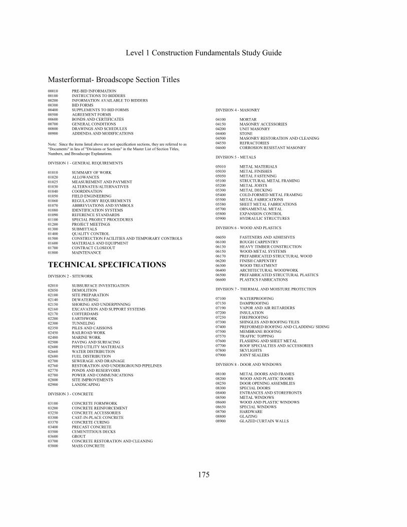
CSI Masterformat SectionsThe CSI Masterformat breaks down Divisions 02 - 16 into Sections using a three-digitnumbering system. For example, in Division 02 - Sitework the Earthwork is under sectionnumber 200. Therefore, the complete Division and Section number is 02200.
Level 1 Construction Fundamentals Study Guide
175
Masterformat- Broadscope Section Titles
00010 PRE-BID INFORMATION00100 INSTRUCTIONS TO BIDDERS00200 INFORMATION AVAILABLE TO BIDDERS00300 BID FORMS00400 SUPPLEMENTS TO BID FORMS00500 AGREEMENT FORMS00600 BONDS AND CERTIFICATES00700 GENERAL CONDITIONS00800 DRAWINGS AND SCHEDULES00900 ADDENDA AND MODIFICATIONS
Note: Since the items listed above are not specification sections, they are referred to as"Documents" in lieu of "Divisions or Sections" in the Master List of Section Titles,Numbers, and Broadscope Explanations.
DIVISION 1 - GENERAL REQUIREMENTS
01010 SUMMARY OF WORK01020 ALLOWANCES01025 MEASUREMENT AND PAYMENT01030 ALTERNATES/ALTERNATIVES01040 COORDINATION01050 FIELD ENGINEERING01060 REGULATORY REQUIREMENTS01070 ABBREVIATIONS AND SYMBOLS01080 IDENTIFICATION SYSTEMS01090 REFERENCE STANDARDS01100 SPECIAL PROJECT PROCEDURES01200 PROJECT MEETINGS01300 SUBMITTALS01400 QUALITY CONTROL01500 CONSTRUCTION FACILITIES AND TEMPORARY CONTROLS01600 MATERIALS AND EQUIPMENT01700 CONTRACT CLOSEOUT01800 MAINTENANCE
TECHNICAL SPECIFICATIONS
DIVISION 2 - SITEWORK
02010 SUBSURFACE INVESTIGATION02050 DEMOLITION02100 SITE PREPARATION02140 DEWATERING02150 SHORING AND UNDERPINNING02160 EXCAVATION AND SUPPORT SYSTEMS02170 COFFERDAMS02200 EARTHWORK02300 TUNNELING02350 PILES AND CAISSONS02450 RAILROAD WORK02480 MARINE WORK02500 PAVING AND SURFACING02600 PIPED UTILITY MATERIALS02660 WATER DISTRIBUTION02680 FUEL DISTRIBUTION02700 SEWERAGE AND DRAINAGE02760 RESTORATION AND UNDERGROUND PIPELINES02770 PONDS AND RESERVOIRS02780 POWER AND COMMUNICATIONS02800 SITE IMPROVEMENTS02900 LANDSCAPING
DIVISION 3 - CONCRETE
03100 CONCRETE FORMWORK03200 CONCRETE REINFORCEMENT03250 CONCRETE ACCESSORIES03300 CAST-IN-PLACE CONCRETE03370 CONCRETE CURING03400 PRECAST CONCRETE03500 CEMENTITIOUS DECKS03600 GROUT03700 CONCRETE RESTORATION AND CLEANING03800 MASS CONCRETE
DIVISION 4 - MASONRY
04100 MORTAR04150 MASONRY ACCESSORIES04200 UNIT MASONRY04400 STONE04500 MASONRY RESTORATION AND CLEANING04550 REFRACTORIES04600 CORROSION RESISTANT MASONRY
DIVISION 5 - METALS
05010 METAL MATERIALS05030 METAL FINISHES05050 METAL FASTENING05100 STRUCTURAL METAL FRAMING05200 METAL JOISTS05300 METAL DECKING05400 COLD-FORMED METAL FRAMING05500 METAL FABRICATIONS05580 SHEET METAL FABRICATIONS05700 ORNAMENTAL METAL05800 EXPANSION CONTROL05900 HYDRAULIC STRUCTURES
DIVISION 6 - WOOD AND PLASTICS
06050 FASTENERS AND ADHESIVES06100 ROUGH CARPENTRY06130 HEAVY TIMBER CONSTRUCTION06150 WOOD-METAL SYSTEMS06170 PREFABRICATED STRUCTURAL WOOD06200 FINISH CARPENTRY06300 WOOD TREATMENT06400 ARCHITECTURAL WOODWORK06500 PREFABRICATED STRUCTURAL PLASTICS06600 PLASTICS FABRICATIONS
DIVISION 7 - THERMAL AND MOISTURE PROTECTION
07100 WATERPROOFING07150 DAMPROOFING07190 VAPOR AND AIR RETARDERS07200 INSULATION07250 FIREPROOFING07300 SHINGLES AND ROOFING TILES07400 PREFORMED ROOFING AND CLADDING/ SIDING07500 MEMBRANE ROOFING07570 TRAFFIC TOPPING07600 FLASHING AND SHEET METAL07700 ROOF SPECIALTIES AND ACCESSORIES07800 SKYLIGHTS07900 JOINT SEALERS
DIVISION 8 - DOOR AND WINDOWS
08100 METAL DOORS AND FRAMES08200 WOOD AND PLASTIC DOORS08250 DOOR OPENING ASSEMBLIES08300 SPECIAL DOORS08400 ENTRANCES AND STOREFRONTS08500 METAL WINDOWS08600 WOOD AND PLASTIC WINDOWS08650 SPECIAL WINDOWS08700 HARDWARE08800 GLAZING08900 GLAZED CURTAIN WALLS

Level 1 Construction Fundamentals Study Guide
176
DIVISION 9 - FINISHES
09100 METAL SUPPORT SYSTEMS09200 LATH AND PLASTER09230 AGGREGATE COATINGS09250 GYPSUM BOARD09300 TILE09400 TERRAZZO09500 ACOUSTICAL TREATMENT09540 SPECIAL SURFACES09550 WOOD FLOORING09600 STONE FLOORING09630 UNIT MASONRY FLOORING09650 RESILIENT FLOORING09680 CARPET09700 SPECIAL FLOORING09780 FLOOR TREATMENT09800 SPECIAL COATINGS09900 PAINTING09950 WALL COVERING
DIVISION 10 - SPECIALTIES
10100 CHALKBOARDS AND TACKBOARDS10150 COMPARTMENTS AND CUBICLES10200 LOUVERS AND VENTS10240 GRILLES AND SCREENS10250 SERVICE WALL SYSTEMS10260 WALL AND CORNER GUARDS10270 ACCESS FLOORING10280 SPECIALTY MODULES10290 PEST CONTROL10300 FIREPLACES AND STOVES10340 PREFABRICATED EXTERIOR SPECIALTIES10350 FLAGPOLES10400 IDENTIFYING DEVICES10450 PEDESTRIAN CONTROL DEVICES10500 LOCKERS10520 FIRE PROTECTION SPECIALTIES10530 PROTECTIVE COVERS10550 POSTAL SPECIALTIES10690 PARTITIONS10650 OPERABLE PARTITIONS10670 STORAGE SHELVING10700 EXTERIOR SUN CONTROL DEVICES10750 TELEPHONE SPECIALTIES10800 TOILET AND BATH ACCESSORIES10880 SCALES10900 WARDROBE AND CLOSET SPECIALTIES
DIVISION 11 - EQUIPMENT
11010 MAINTENANCE EQUIPMENT11020 SECURITY AND VAULT EQUIPMENT11030 TELLER AND SERVICE EQUIPMENT11040 ECCLESIASTICAL EQUIPMENT11050 LIBRARY EQUIPMENT11060 THEATER AND STAGE EQUIPMENT11070 INSTRUMENTAL EQUIPMENT11080 REGISTRATION EQUIPMENT11090 CHECKROOM EQUIPMENT11100 MERCANTILE EQUIPMENT11110 COMMERCIAL LAUNDRY AND DRY CLEANING EQUIPMENT11120 VENDING EQUIPMENT11130 AUDIO-VISUAL EQUIPMENT11140 SERVICE STATION EQUIPMENT11150 PARKING CONTROL EQUIPMENT11160 LOADING DOCK EQUIPMENT11170 SOLID WASTE HANDLING EQUIPMENT11190 DETENTION EQUIPMENT11200 WATER SUPPLY AND TREATMENT EQUIPMENT11280 HYDRAULIC GATES AND VALVES11300 FLUID WASTE TREATMENT AND DISPOSAL EQUIPMENT11400 FOOD SERVICE EQUIPMENT11450 RESIDENTIAL EQUIPMENT11460 UNIT KITCHENS11470 DARKROOM EQUIPMENT11480 ATHLETIC, RECREATIONAL AND THERAPEUTIC EQUIPMENT11500 INDUSTRIAL AND PROCESS EQUIPMENT11600 LABORATORY EQUIPMENT11650 PLANETARIUM EQUIPMENT11660 OBSERVATORY EQUIPMENT
11700 MEDICAL EQUIPMENT11780 MORTUARY EQUIPMENT
11850 NAVIGATION EQUIPMENT
DIVISION 12 - FURNISHINGS
12050 FABRICS12100 ARTWORK12300 MANUFACTURED CASEWORK12500 WINDOW TREATMENT12600 FURNITURE AND ACCESSORIES12670 RUGS AND MATS12700 MULTIPLE SEATING12800 INTERIOR PLANTS AND PLANTERS
DIVISION 13 - SPECIAL CONSTRUCTION
13010 AIR SUPPORTED STRUCTURES13020 INTEGRATED ASSEMBLIES13030 SPECIAL PURPOSE ROOMS13080 SOUND, VIBRATION, AND SEISMIC CONTROL13090 RADIATION PROTECTION13100 NUCLEAR REACTORS13120 PRE-ENGINEERED STRUCTURES13150 POOLS13160 ICE RINKS13170 KENNELS AND ANIMAL SHELTERS13180 SITE CONSTRUCTED INCINERATORS13200 LIQUID AND GAS STORAGE TANKS13220 FILTER UNDERDRAINS AND MEDIA13230 DIGESTION TANK COVERS AND APPURTENANCES13240 OXYGENATION SYSTEMS13260 SLUDGE CONDITIONING SYSTEMS13300 UTILITY CONTROL SYSTEMS13400 INDUSTRIAL AND PROCESS CONTROL SYSTEMS13500 RECORDING INSTRUMENTATION13550 TRANSPORTATION CONTROL INSTRUMENTATION13600 SOLAR ENERGY SYSTEMS13700 WIND ENERGY SYSTEMS13800 BUILDING AUTOMATION SYSTEMS13900 FIRE SUPPRESSION AND SUPERVISORY SYSTEMS
DIVISION 14 - CONVEYING SYSTEMS
14100 DUMBWAITERS14200 ELEVATORS14300 MOVING STAIRS AND WALKS14400 LIFTS14500 MATERIAL HANDLING SYSTEMS14600 HOISTS AND CRANES14700 TURNTABLES14800 SCAFFOLDING14900 TRANSPORTATION SYSTEMS
DIVISION 15 - MECHANICAL
15050 BASIC MECHANICAL MATERIALS AND METHODS15250 MECHANICAL INSULATION15300 FIRE PROTECTION15400 PLUMBING15500 HEATING, VENTILATING, AND AIR CONDITIONING (HVAC)15550 HEAT GENERATION15650 REFRIGERATION15750 HEAT TRANSFER15850 AIR HANDLING15880 AIR DISTRIBUTION15950 CONTROLS15990 TESTING, ADJUSTING, AND BALANCING
DIVISION 16 - ELECTRICAL
16050 BASIC ELECTRICAL MATERIALS AND METHODS16200 POWER GENERATION16300 HIGH VOLTAGE DISTRIBUTION (ABOVE 600-VOLT)16400 SERVICE AND DISTRIBUTION (600-VOLT AND BELOW)16500 LIGHTING16600 SPECIAL SYSTEMS16700 COMMUNICATIONS16850 ELECTRIC RESISTANCE HEATING16900 CONTROLS16950 TESTING
Level 1 Construction Fundamentals Study Guide
177
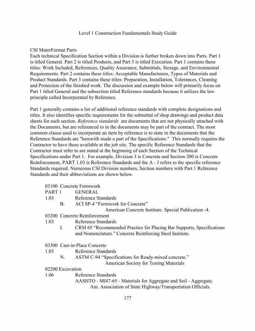
CSI MaterFormat PartsEach technical Specification Section within a Division is further broken down into Parts. Part 1is titled General. Part 2 is titled Products, and Part 3 is titled Execution. Part 1 contains thesetitles: Work Included, References, Quality Assurance, Submittals, Storage, and EnvironmentalRequirements. Part 2 contains these titles: Acceptable Manufacturers, Types of Materials andProduct Standards. Part 3 contains these titles: Preparation, Installation, Tolerances, Cleaningand Protection of the finished work. The discussion and example below will primarily focus onPart 1 titled General and the subsection titled Reference standards because it utilizes the lawprinciple called Incorporated by Reference.
Part 1 generally contains a list of additional reference standards with complete designations andtitles. It also identifies specific requirements for the submittal of shop drawings and product datasheets for each section. Reference standards are documents that are not physically attached withthe Documents, but are referenced to in the documents may be part of the contract. The mostcommon clause used to incorporate an item by reference is to state in the documents that theReference Standards are "herewith made a part of the Specifications." This normally requires theContractor to have these available at the job site. The specific Reference Standards that theContractor must refer to are stated at the beginning of each Section of the TechnicalSpecifications under Part 1. For example, Division 3 is Concrete and Section 200 is ConcreteReinforcement, PART 1.03 is Reference Standards and the A - J refers to the specific referenceStandards required. Numerous CSI Division numbers, Section numbers with Part 1 ReferenceStandards and their abbreviations are shown below.
03100 Concrete FormworkPART 1 GENERAL1.03 Reference Standards
B. ACI SP-4 “Formwork for Concrete”American Concrete Institute. Special Publication -4.
03200 Concrete Reinforcement1.03 Reference Standards
I. CRSI 65 “Recommended Practice for Placing Bar Supports, Specificationsand Nomenclature.” Concrete Reinforcing Steel Institute.
03300 Cast-in-Place Concrete1.03 Reference Standards
N. ASTM C-94 “Specifications for Ready-mixed concrete.”American Society for Testing Materials
02200 Excavation 1.06 Reference Standards
AASHTO - MI47-65 - Materials for Aggregate and Soil - Aggregate. Am. Association of State Highway/Transportation Officials.
Level 1 Construction Fundamentals Study Guide
178
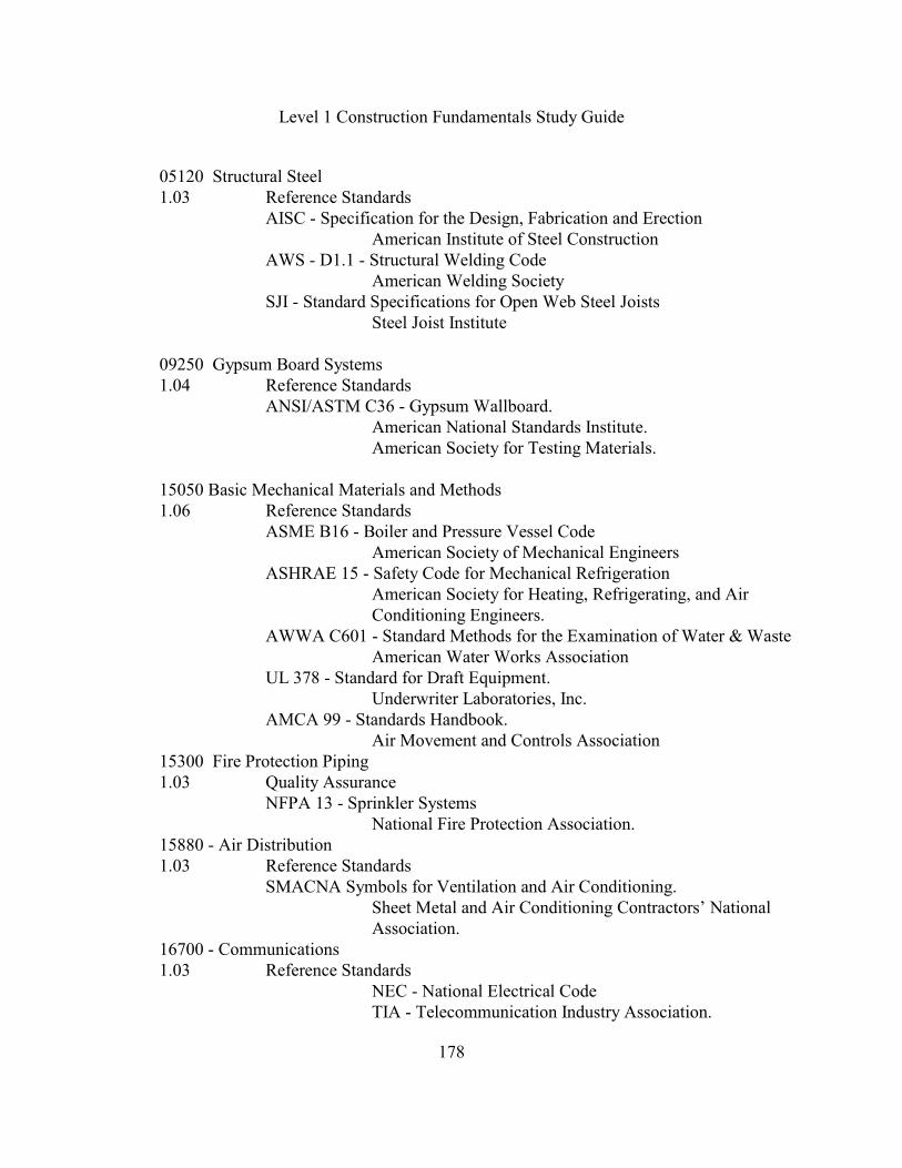
05120 Structural Steel1.03 Reference Standards
AISC - Specification for the Design, Fabrication and ErectionAmerican Institute of Steel Construction
AWS - D1.1 - Structural Welding CodeAmerican Welding Society
SJI - Standard Specifications for Open Web Steel JoistsSteel Joist Institute
09250 Gypsum Board Systems1.04 Reference Standards
ANSI/ASTM C36 - Gypsum Wallboard.American National Standards Institute.American Society for Testing Materials.
15050 Basic Mechanical Materials and Methods1.06 Reference Standards
ASME B16 - Boiler and Pressure Vessel CodeAmerican Society of Mechanical Engineers
ASHRAE 15 - Safety Code for Mechanical RefrigerationAmerican Society for Heating, Refrigerating, and AirConditioning Engineers.
AWWA C601 - Standard Methods for the Examination of Water & WasteAmerican Water Works Association
UL 378 - Standard for Draft Equipment.Underwriter Laboratories, Inc.
AMCA 99 - Standards Handbook.Air Movement and Controls Association
15300 Fire Protection Piping1.03 Quality Assurance
NFPA 13 - Sprinkler SystemsNational Fire Protection Association.
15880 - Air Distribution1.03 Reference Standards
SMACNA Symbols for Ventilation and Air Conditioning.Sheet Metal and Air Conditioning Contractors’ NationalAssociation.
16700 - Communications1.03 Reference Standards
NEC - National Electrical CodeTIA - Telecommunication Industry Association.
Level 1 Construction Fundamentals Study Guide
179
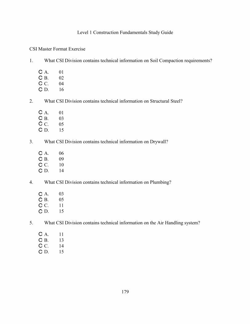
CSI Master Format Exercise
1. What CSI Division contains technical information on Soil Compaction requirements?
A. 01B. 02 C. 04D. 16
2. What CSI Division contains technical information on Structural Steel?
A. 01B. 03C. 05D. 15
3. What CSI Division contains technical information on Drywall?
A. 06B. 09C. 10D. 14
4. What CSI Division contains technical information on Plumbing?
A. 03B. 05C. 11D. 15
5. What CSI Division contains technical information on the Air Handling system?
A. 11B. 13C. 14D. 15
Level 1 Construction Fundamentals Study Guide
180
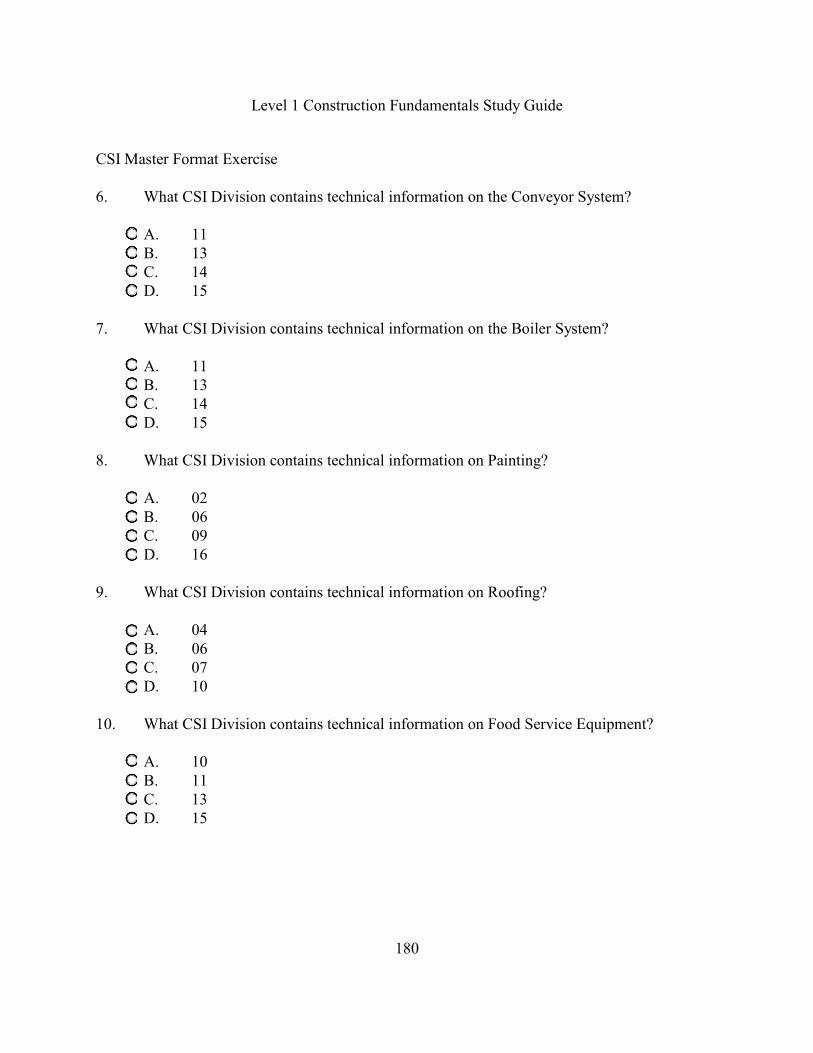
CSI Master Format Exercise
6. What CSI Division contains technical information on the Conveyor System?
A. 11B. 13C. 14D. 15
7. What CSI Division contains technical information on the Boiler System?
A. 11B. 13C. 14D. 15
8. What CSI Division contains technical information on Painting?
A. 02B. 06C. 09D. 16
9. What CSI Division contains technical information on Roofing?
A. 04B. 06C. 07D. 10
10. What CSI Division contains technical information on Food Service Equipment?
A. 10B. 11C. 13D. 15
Level 1 Construction Fundamentals Study Guide
181
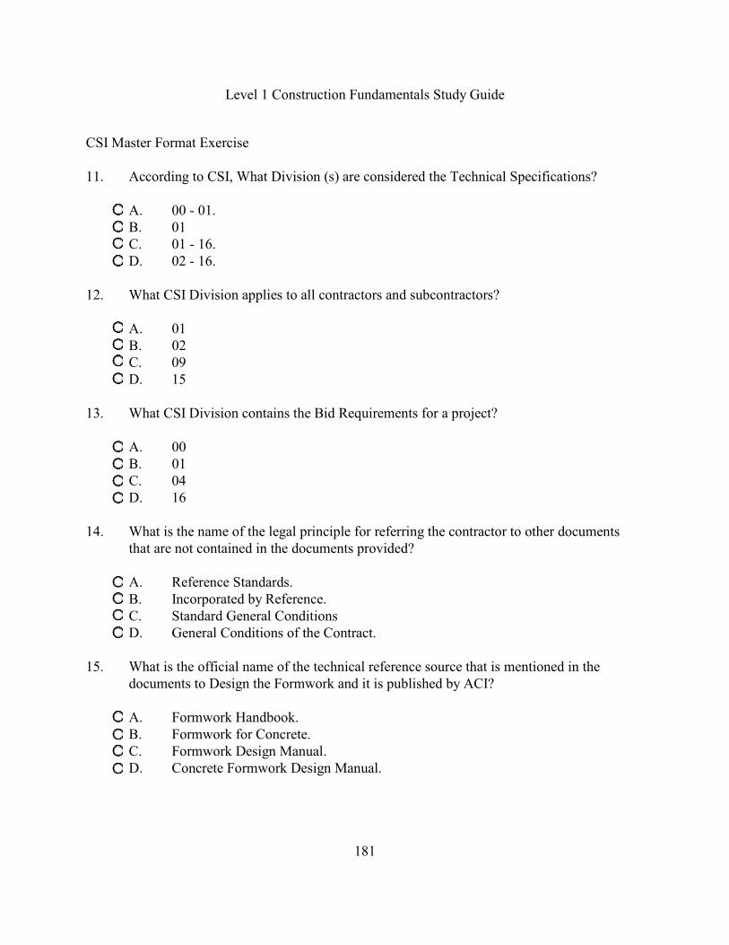
CSI Master Format Exercise
11. According to CSI, What Division (s) are considered the Technical Specifications?
A. 00 - 01. B. 01
C. 01 - 16.D. 02 - 16.
12. What CSI Division applies to all contractors and subcontractors?
A. 01B. 02C. 09D. 15
13. What CSI Division contains the Bid Requirements for a project?
A. 00B. 01C. 04D. 16
14. What is the name of the legal principle for referring the contractor to other documentsthat are not contained in the documents provided?
A. Reference Standards.B. Incorporated by Reference.C. Standard General ConditionsD. General Conditions of the Contract.
15. What is the official name of the technical reference source that is mentioned in thedocuments to Design the Formwork and it is published by ACI?
A. Formwork Handbook.B. Formwork for Concrete.C. Formwork Design Manual.D. Concrete Formwork Design Manual.

Level 1 Construction Fundamentals Study Guide
182
CSI Master Format Exercise
16. What is the official name of the technical reference source that is mentioned in thedocuments to Place the Slab Bolsters and it is published by CRSI?
A. Steel Riggers Handbook.B. Steel Reinforcement Guide.C. Recommended Practice for Placing Bar Supports, Specifications & Nomenclature.D. Manual of Steel Erection Practices.
17. Your specifications reference this construction organization Acronym of ACI thatpublishes numerous Technical Reference Sources. What is the correct name of ACI?
A. American Concrete Institute.B. Associated Contractors Institute.C. American Construction Institute.D. Associated Constructors Institute.
18. Your specifications reference this construction organization Acronym of CSI thatpublishes numerous Technical Reference Sources. What is the correct name of CSI?
A. Cost System Information.B. Construction Standards Institute.C. Construction Standards Information.D. Construction Specifications Institute.
19. Your specifications reference this construction organization Acronym of CRSI thatpublishes numerous Technical Reference Sources. What is the correct name of CRSI?
A. Concrete Reinforcing Steel Institute.B. Crane and Riggers Specification Institute.C. Concrete Reinforcement Standards InstituteD. Concrete Reinforcement Specifications Institute.
20. Your specifications reference this construction organization Acronym of AISC thatpublishes numerous Technical Reference Sources. What is the correct name of AISC?
A. American Institute of Steel Contractors.B. American Institute of Steel Constructors.C. American Institute of Steel Construction.D. American Institute of Structural Concrete.
Level 1 Construction Fundamentals Study Guide
183
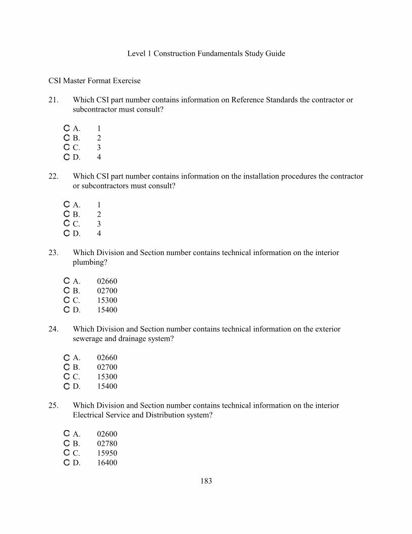
CSI Master Format Exercise
21. Which CSI part number contains information on Reference Standards the contractor orsubcontractor must consult?
A. 1B. 2C. 3D. 4
22. Which CSI part number contains information on the installation procedures the contractoror subcontractors must consult?
A. 1B. 2C. 3D. 4
23. Which Division and Section number contains technical information on the interiorplumbing?
A. 02660B. 02700C. 15300D. 15400
24. Which Division and Section number contains technical information on the exteriorsewerage and drainage system?
A. 02660B. 02700C. 15300D. 15400
25. Which Division and Section number contains technical information on the interiorElectrical Service and Distribution system?
A. 02600B. 02780C. 15950D. 16400

Level 1 Construction Fundamentals Study Guide
184
CSI Master Format Exercise
26. Which Division and Section number contains technical information on thecommunications systems?
A. 02780B. 15950C. 16500D. 16700
27. Your specifications reference this construction organization Acronym of ASHRAE thatpublishes numerous Technical Reference Sources. What is the correct name ofASHRAE?
A. American Steel Housing Rating Association of Engineers.B. Associated Structural Hoists Rating Association of Engineers.C. American Society for Heating, Refrigerating and Air Conditioning Engineers.D. Associated Society for Heating, Refrigerating and Air Conditioning Engineers.
28. Your specifications reference this construction organization Acronym of TIA thatpublishes numerous Technical Reference Sources. What is the correct name of TIA?
A. Trade Industry Association.B. Testing Industry Association.C. Transportation Industry of America.D. Telecommunication Industry Association.
29. Your specifications reference this construction organization Acronym of UL thatpublishes numerous Technical Reference Sources. What is the correct name of UL?
A. Union Laboratories.B. United Laboratories.C. Utility Laboratories.D. Underwriter Laboratories.
Level 1 Construction Fundamentals Study Guide
185
Construction Methods. Materials and Equipment
The contractor is responsible for the temporary shoring system selected and the design of theshoring system. These are not shown on the plans or described in any detail within theconstruction documents. The estimator is responsible for determining the number, size and costfor all temporary structures. These structures are normally utilized to restrain water, soil, existingstructures, etc. Some of the more common temporary systems are described below.
Temporary Shoring SystemsThe Cofferdam is a water tight rectangular structure built to restrain water and soil. It is utilizedaround the foundations of bridge piers or to have working space to place an item below grade. Acofferdam contains driven sheet piling (Uprights), wales(Walers) and Cross braces (Struts). Toensure structural soundness of the cofferdam, the sheet piles are driven beyond the bottom of theexcavation at least two feet. This extension is called the Toe. The most common materials forconstruction of a cofferdam are wood timber and structural steel. If moderate ground water isencountered, Tongue & Groove sheeting is normally utilized to keep out the water. Ifconsiderable water is present, steel sheet piling is used.
Cribbing and Tie Backs shoring is a method of restraining a vertical wall of soil where it isimpractical to slope the soil such as in a downtown area where the excavation and newsubstructure are below the street level. This system requires timbers called cribbing to be placedhorizontally with rods (tiebacks) drilled through the cribbing at an angle back into the soil. Thisshoring system allows the contractor to maximize the open space.
Underpinning is the process of supporting an existing structure when the new excavation will bebelow the existing structures foundation. This requires temporary supports to support thestructure while an extension to the existing foundation is being placed.
Dewatering is the process of removing water or in some cases lowering the water table to installan item below the existing water table. There are two dewatering methods. The first method is byutilizing a pump with a suction hose and discharge hose. The second method is to utilize wellspoints placed at specified intervals to lower the water table temporarily.
Equipment Mobilization is the process of loading off- road equipment, transporting it to the jobsite and assembling at the site. The assembly of a large lifting crane can require 7 -9 workersapproximately three days if the crane requires the boom to be assembled and the cables to be runthrough the crane’s jib. Equipment Demobilization is the process of disassembling equipment.

Level 1 Construction Fundamentals Study Guide
186
Excavation Shoring SystemsA Support or Shoring System is a structure such as a timber shoring system or hydraulic shoringsystem that supports the sides of an excavation and protects employees against cave-ins.According to the OSHA Excavation Safety Standards, anytime a worker enters a trench at leastfive (5) feet deep you must provide protection from cave-ins. After a qualified person hasdetermined the type of soil, they have a few options. First, they can design a shoring system usingthe Shoring Designs provided in the Standards. The Second option is to design a support systemusing a Manufacturer's system. Finally, they can use a trench box. Below we will define theshoring options outlined in the excavation safety standards for shoring systems less than twentyfeet deep. According to the OSHA Construction Standards, for excavations more than twenty(20) feet deep you must contact a Registered Professional Engineer (RPE) to design theprotection system.
The OSHA Standards for the Construction Industry 29 CFR Part 1926.650(b) titled, Definitionsapplicable to subpart P - Excavations defines the following shoring terms. The Sheeting means the individual members of a shoring system that are closely spaced togetherto retain the earth. Sheeting is also called Uprights or Sheet Piling. OSHA defines the term“Uprights”as the vertical members of a trench shoring system placed in contact with the earthand usually positioned so that individual members do not contact each other (p 253).
The Wales means the horizontal members of a shoring system placed parallel to the excavationface whose sides bear against the vertical members of the shoring system. They are setperpendicular to the sheeting. The Crossbraces or Struts are the horizontal members of theshoring system that span across the width of an excavation. They are installed perpendicular tothe sides of the excavation and the ends are connected to either uprights or wales.
OSHA also defines Tight Sheeting as the use of specially-edged timber planks (e.g. Tongue andGroove) at least three inches thick. These are used when conditions are saturated or submerged inwater as defined in the OSHA 1926.652(g). Also, Close Sheeting refers to the space between thetimber planks not to exceed ½ inch when placed edge to edge according to OSHA 1926.652(g),titled Notes for all Tables in paragraph 2.
The Shield or Trench Box is a structure that normally does not prevent a cave-in but protectsemployees within the structure. Shields may be permanent structures or may be designed to beportable and moved along the trench. Shields used in trenches are usually referred to as "trenchboxes" or "trench shields.”
Level 1 Construction Fundamentals Study Guide
187
Concrete Support SystemsConcrete Formwork is a temporary support system for restraining the compressive force from theconcrete. The OSHA Standards for the Construction Industry 29 CFR Part 1926.700(b) titled,Definitions applicable to subpart Q - Concrete and Masonry Construction defines the followingformwork terms. Formwork is the total system of support for freshly placed or partially curedconcrete, including the sheeting that is in contact with the concrete as well as all supportingmembers including shores, reshores, hardware, braces, and related hardware. Shoring means asupporting member that resists a compressive force imposed by a load. Reshoring means theconstruction operation in which shoring equipment called reshores is placed, as the originalforms and shores are removed, in order to support partially cured concrete and construction loadsfor elevated slab and beams. The slip form system is used to make a continuous vertical concretepour which moves up on the freshly poured concrete at a constant speed.
Another temporary operation is called a Lift-Slab or a jacking operation which takes curedconcrete slabs and lifts them vertically into placed using hydraulic jacks. An additionaltemporary system is called tilt-up construction. This system has the concrete poured on theground into panels and after they are cured they are lifted or tilted up into place vertically.Finally, there is a formwork system called a flying deck form system which is a completeformwork support system that is repositioned using a crane for the next pour.
There are various methods for pouring the concrete such as direct chute, crane and bucket,concrete buggies, concrete pumping, tremie, shotcrete and sometimes by conveyor. The Concretebucket is attached to the crane and a person pulls on a handle which opens the bottom of thebucket and pours concrete. This method is called the crane and bucket operation. There are twotypes of concrete buggies: Hand or Georgia buggies and the motorized buggies. The handGeorgia buggy has a very limited capacity of about 1.5 cubic feet, therefore, it is used to movesmall amounts of concrete. The Motorized Concrete Buggy is a small rubber tired vehicle with adump box that carries up to 14 cubic feet. A Concrete pump is a truck mounted equipped with aplacement boom or hose which pressurizes the hose system to pump the concrete to elevatedlocations or an inaccessible location. Tremie is the process of pouring concrete under water usinga tube that is submerged into the fresh concrete at all times.
The Structural Engineering Institute (SEI) of the American Society of Civil Engineers (ASCE)insists that “more failures occur during construction than after completion”, therefore, they havedeveloped a standard titled, SEI/ASCE 37-02, Design Loads on Structures During Construction.Another temporary area that fails during construction is the masonry wall bracing. Under theConstruction OSHA Standards Part 1926.700 titled Masonry Construction it states thattemporary bracing should be provided for walls more than 8 feet high and the bracing shall notexceed 20 feet horizontally. Recently, the Masonry Institute has developed a temporary masonrybracing standard for construction.
Level 1 Construction Fundamentals Study Guide
188
Lifting Systems The Jin Pole is a lifting system which utilizes a single pole or double pole above grade verticallifting system with the intended purpose of lifting an unusually long horizontal piece ofequipment into its permanent vertical position. The Jin poles are attached to a temporaryfoundation and the guy lines are attached to the top of each Jin pole and tied to deadmen buriedin the ground.
Cranes are used to hoist and move loads from one location to another and it is necessary to knowthe lifting capacity and working range of a crane selected to perform a given service. Manufacturers and suppliers furnish this information in literature describing their products.When a crane lifts a load there is a tendency to tip the machine over. This introduces what isdefined as the tipping condition. A machine is considered to be at the point of tipping when abalance is reached between the overturning moment of the load and the stabilizing moment of themachine when the crane is on a firm level supporting surface. A track mounted or a crawlermounted crane sets on a track base which rotates 360 degrees and the boom is attached at thebase of the crane. A rubber tired crane is extremely mobile and it can be easily transported fromone job site to another over the road. The crane mat is normally made of large square timbers tiedtogether using cables threaded through the center of the timbers at specified spacings. It is best toplace the crane on a mat to ensure that the load is distributed evenly. Tower Cranes are available as rail mounted units, stationary units, climbing units and mobileunits. The rail mounted units can be equipped with fixed or slewing towers. Tower cranesgenerally have a larger area of coverage than climbing and stationary tower cranes. Tower craneshave their boom above the structure and it lifts the load vertically until it is above the structure,then it can move the load horizontally. A tower crane looks like an offset Tee.
A Crane Load Capacity Chart is provided with each crane by the crane manufacturer whichindicates its safe lifting capacity under differing conditions. The major factor for safely lifting aload by a crane is its operating radius which is the horizontal distance from the center of therotation to the hook. Some other factors which affect lifting capacity are the position of the cranein relationship to its base, the placement or use of outriggers and the soil conditions. Also, theboom angle for a crawler mounted lifting crane is normally between 55 degrees and 80 degrees.
Working Range of a Crane Chart This crane table shows lifting ranges for a dragline, a clamshell and a lifting crane. From the cranetable, the working range of a dragline is from 25 degrees to 39 degrees, the clamshell range isbetween 40 degrees and 54 degrees and the crane lifting range is between 55 degrees and 80degrees. The crane chart also contains the distance from the center line rotation in feet along thehorizontal axis and the height of a structure in feet such as a wall along the vertical structure. Toutilize the chart, let’s assume that you are lifting an item over a vertical wall that is 45 feet abovethe ground and the horizontal distance from the centerline of the rotation is 60 feet.

Level 1 Construction Fundamentals Study Guide
189
The fist step is to find the working range for a lifting crane which is between 55 degrees and 80degrees. Next, find the length of boom in feet required by determining if the rotation distance orthe height above the ground is the controlling factor. In this example, using the height in feetabove the ground of 45 feet and in the lifting crane range of 55 - 80 degrees the length of boom,the curved lines, needed is 50 feet. Now, using the center line rotation in feet of 60 feet and in thelifting crane range of 55 - 80 degrees the length of boom needed is 100 feet. This is found byentering the table along the horizontal axis at 60 feet and following the vertical line until it inwithin the lifting crane range and finding the intersection of the length of boom in feet curved lineand the vertical (60 feet) line. The Crane Chart below indicates the working range of a crane.
Adapted from Peurifoy (1985). Construction Planning, Equipment, and Methods. Upper SaddleRiver, NJ: Prentice-Hall. (p 224).
Level 1 Construction Fundamentals Study Guide
190
Sling Angles are formed by the legs of the sling and the horizontal plane and the rated capacity ofany sling depends on its size, its configuration and the angles. A sling with two legs that is used tolift a 1000 pound object will have a 500 pound load in each leg when the sling angle is 90degrees. The load in each leg will increase as the angle is decreased and at 30 degrees the loadwill be 1000 pounds in each leg. Therefore, it is extremely important to keep the sling anglesgreater than 45 degrees. Hence, sling angles approaching 30 degrees should be consideredextremely hazardous and avoided at all costs. Some load tables list sling angles as low as 15degrees but the use of any sling at an angle less than 30 degrees is extremely dangerous. This isnot only because of the high loads associated with them but because of the effect on the load of anerror in sling angle measurement of as little as 5 degrees. It has been shown that an assumed slingangle of 15 degrees has an assumed load of 1,932 pounds per Leg but, if the actual angle isactually 10 degrees then the actual load is 2,880 pounds per leg. This illustrates how cautious youmust be in ensuring that the angle is greater than 45 degrees and the importance of measuring theangle accurately.
The major types of crane attachments are the lift hook, the lifting beam and hook, the concretebucket, the clamshell bucket, orange peel bucket, the pile driver, the auger or drilled attachment,and the dragline. Each attachment is described below. The Lift Hook has a sling or a configurationof slings connected to the hook on the crane. The Lifting Beam is utilized to lift long items such asbeams for a bridge. The Beam has two lifting at each end with the crane hook connected to thecenter of the lifting beam. The Clamshell bucket opens and is dropped straight down into the soilbeing excavated and the jaws close toward each other. The Clamshell bucket is utilized toexcavate inside the cofferdam after the sheet piles are driven. The Orange Peel bucket is similarto the Clamshell bucket but it opens and has straighter sides and it is dropped straight down intothe soil being excavated and the jaws close toward each other. The Pile Driver can replace theboom or it can be attached to the boom via the hook and suspended from the crane. The Auger orDrilled pile is an attachment to the crane for drilling Caissons. These drill attachments have amechanical device at the bottom of the caisson to form the bell.
Finally, the Dragline is used to excavate earth and load it into hauling units, such as trucks ortractor-pulled wagons, or to deposit it in levees, dams, and spoil banks near the pits from which itis excavated. A dragline usually does not have to go into a pit or hole in order to excavate. It mayoperate on natural ground while excavating material from a pit with its bucket. This will be veryadvantageous when earth is removed from a ditch, canal, or pit containing water. If the earth ishauled with trucks, they do not have to go into the pit and contend with mud. If the earth can bedeposited along a canal or ditch or near a pit, it frequently is possible to use a dragline with aboom long enough to dispose of the earth in one operation, eliminating the need for hauling units,which will reduce the cost of handling the soil. A Dragline is an excellent unit for excavatingtrenches when an angle of repose can be utilized without shoring.
Level 1 Construction Fundamentals Study Guide
191
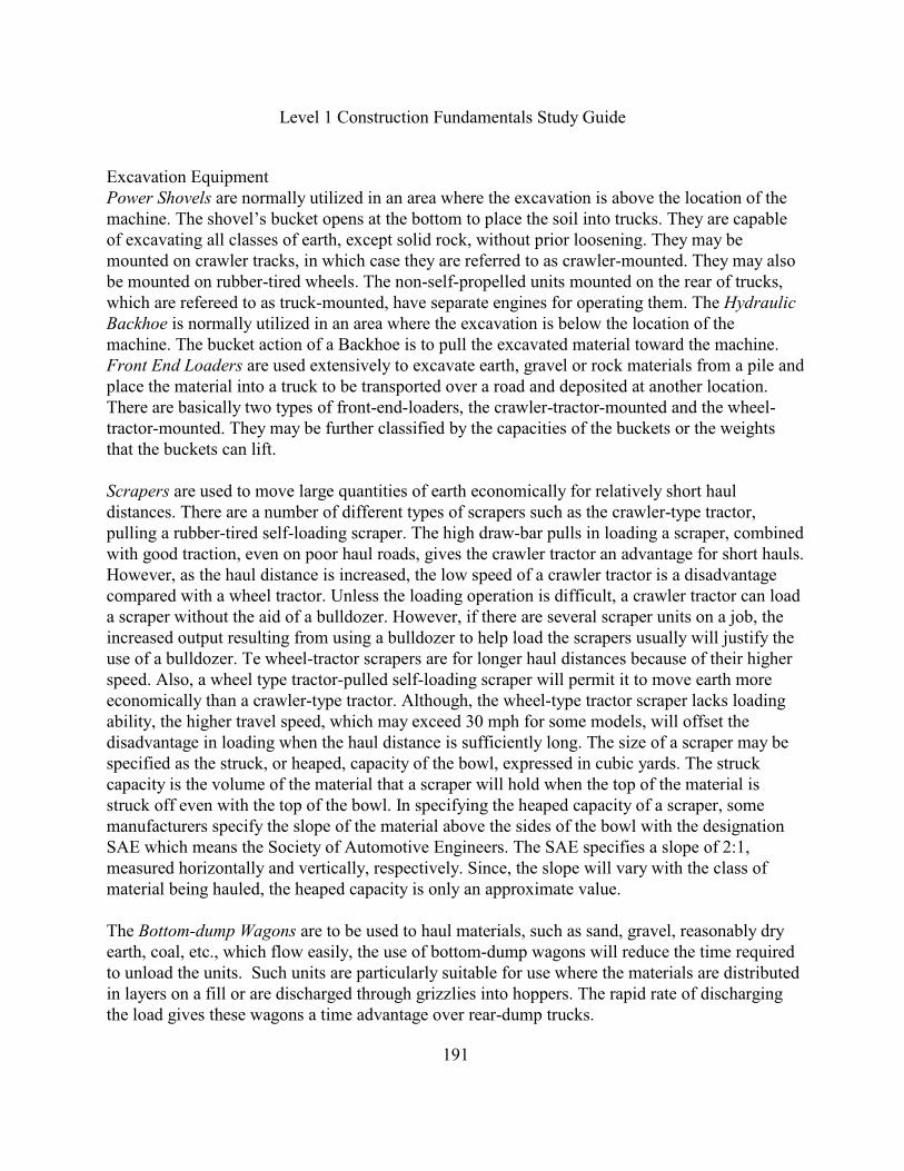
Excavation EquipmentPower Shovels are normally utilized in an area where the excavation is above the location of themachine. The shovel’s bucket opens at the bottom to place the soil into trucks. They are capableof excavating all classes of earth, except solid rock, without prior loosening. They may bemounted on crawler tracks, in which case they are referred to as crawler-mounted. They may alsobe mounted on rubber-tired wheels. The non-self-propelled units mounted on the rear of trucks,which are refereed to as truck-mounted, have separate engines for operating them. The HydraulicBackhoe is normally utilized in an area where the excavation is below the location of the machine. The bucket action of a Backhoe is to pull the excavated material toward the machine.Front End Loaders are used extensively to excavate earth, gravel or rock materials from a pile andplace the material into a truck to be transported over a road and deposited at another location. There are basically two types of front-end-loaders, the crawler-tractor-mounted and the wheel-tractor-mounted. They may be further classified by the capacities of the buckets or the weightsthat the buckets can lift.
Scrapers are used to move large quantities of earth economically for relatively short hauldistances. There are a number of different types of scrapers such as the crawler-type tractor,pulling a rubber-tired self-loading scraper. The high draw-bar pulls in loading a scraper, combinedwith good traction, even on poor haul roads, gives the crawler tractor an advantage for short hauls.However, as the haul distance is increased, the low speed of a crawler tractor is a disadvantagecompared with a wheel tractor. Unless the loading operation is difficult, a crawler tractor can loada scraper without the aid of a bulldozer. However, if there are several scraper units on a job, theincreased output resulting from using a bulldozer to help load the scrapers usually will justify theuse of a bulldozer. Te wheel-tractor scrapers are for longer haul distances because of their higherspeed. Also, a wheel type tractor-pulled self-loading scraper will permit it to move earth moreeconomically than a crawler-type tractor. Although, the wheel-type tractor scraper lacks loadingability, the higher travel speed, which may exceed 30 mph for some models, will offset thedisadvantage in loading when the haul distance is sufficiently long. The size of a scraper may bespecified as the struck, or heaped, capacity of the bowl, expressed in cubic yards. The struckcapacity is the volume of the material that a scraper will hold when the top of the material isstruck off even with the top of the bowl. In specifying the heaped capacity of a scraper, somemanufacturers specify the slope of the material above the sides of the bowl with the designationSAE which means the Society of Automotive Engineers. The SAE specifies a slope of 2:1,measured horizontally and vertically, respectively. Since, the slope will vary with the class ofmaterial being hauled, the heaped capacity is only an approximate value.
The Bottom-dump Wagons are to be used to haul materials, such as sand, gravel, reasonably dryearth, coal, etc., which flow easily, the use of bottom-dump wagons will reduce the time requiredto unload the units. Such units are particularly suitable for use where the materials are distributedin layers on a fill or are discharged through grizzlies into hoppers. The rapid rate of dischargingthe load gives these wagons a time advantage over rear-dump trucks.
Level 1 Construction Fundamentals Study Guide
192
Compaction EquipmentThe Technical Specifications normally state the compaction method and the optimum moisturecontent range. The measurement testing method for determining if the desired compaction has beattained is the Modified Proctor Test or the Standard Proctor Test. For a contractor to attain theprescribed compaction, it must determine the number of passes for a roller with a specified unitpressure under the roller areas and the depth of each layer of soil to produce the desiredcompaction. Compaction is attained by applying energy to a soil by one or more of the followingmethods. The different methods to apply the energy is by a kneading or tamping action, a staticweight, a vibrating action, or an impacting force. The common pieces of compaction methods aredescribed below.
A kneading roller is the sheep's-foot type. This roller, which may be towed by a tractor or self-propelled, consists of a hollow steel drum on whose outer surface there are welded a number ofprojecting steel feet, which on different pieces of equipment may be of varying lengths and crosssections. A unit may consist of one or several drums mounted on one or more horizontal axles. The weight of a drum may be varied by adding water or sand to produce unit pressures under thefeet up to 750 psi or more. As a sheep’s foot roller moves over the surface, the feet penetrate thesoil to produce a kneading action and a pressure to mix and compact the soil from the bottom tothe top of the layer. With repeated passages of the roller over the surface, the penetration of thefeet decreases until the roller is said to walk out of the fill. The Sheep's-foot rollers are quiteeffective in compacting clays and clay mixtures. However, they cannot compact granular soilssuch as sand and gravel. Also, the depth of a layer of soil to be compacted is limited tooapproximately the length of the feet.
Smooth-wheel Rollers may be classified by weight, which is usually stated in tons. A three-wheeltwo-axle roller. The front wheel is used for steering, while the two rear wheels are used fordriving the unit. A two-wheel tandem roller of varying size is available. A three-wheel tandemroller differs from the two-wheel tandem unit in that it has three drums and three axles. This unitcan be more effective than the two-wheel tandem or the three-wheel two-axle units in eliminatingor reducing transverse surface roughness because of the concentration of pressure on the middlewheel when the unit passes over high spots in the surface being compacted. The rolls are steeldrums, which may be ballasted with water or sand to increase the weights. If a roller is designatedas 14-20 tons, it means that the minimum weight of the machine only is 14 tons and that it can beballasted to give a maximum weight of 20 tons. These rollers are effective in compacting granularsoils, such as sand, gravel, and crushed stone, and they are also effective in smoothing surfaces ofsoils that have been compacted by tamping rollers. Another type designates the weight per linearinch of roller, such as 300 lb. per inch of roller width. Specifying the minimum weight per linearinch of width is a more definitive method.
Pneumatic-tired Rollers are surface rollers which apply the principle of kneading action to affectcompaction below the surface. They may be self-propelled or towed and they may be small or
Level 1 Construction Fundamentals Study Guide
193
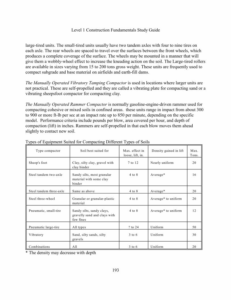
large-tired units. The small-tired units usually have two tandem axles with four to nine tires oneach axle. The rear wheels are spaced to travel over the surfaces between the front wheels, whichproduces a complete coverage of the surface. The wheels may be mounted in a manner that willgive them a wobbly-wheel effect to increase the kneading action on the soil. The Large-tired rollersare available in sizes varying from 15 to 200 tons gross weight. These units are frequently used tocompact subgrade and base material on airfields and earth-fill dams.
The Manually Operated Vibratory Tamping Compactor is used in locations where larger units arenot practical. These are self-propelled and they are called a vibrating plate for compacting sand or avibrating sheepsfoot compactor for compacting clay.
The Manually Operated Rammer Compactor is normally gasoline-engine-driven rammer used forcompacting cohesive or mixed soils in confined areas. these units range in impact from about 300to 900 or more ft-lb per sec at an impact rate up to 850 per minute, depending on the specificmodel. Performance criteria include pounds per blow, area covered per hour, and depth ofcompaction (lift) in inches. Rammers are self-propelled in that each blow moves them aheadslightly to contact new soil.
Types of Equipment Suited for Compacting Different Types of Soils
Type compactor Soil best suited for Max. effect in
loose, lift, in.
Density gained in lift Max.
Tons.
Sheep's foot Clay, silty clay, gravel with
clay binder
7 to 12 Nearly uniform 20
Steel tandem two-axle Sandy silts, most granular
material with some clay
binder
4 to 8 Average* 16
Steel tandem three-axle Same as above 4 to 8 Average* 20
Steel three-wheel Granular or granular-plastic
material
4 to 8 Average* to uniform 20
Pneumatic, small-tire Sandy silts, sandy clays,
gravelly sand and clays with
few fines
4 to 8 Average* to uniform 12
Pneumatic large-tire All types ? to 24 Uniform 50
Vibratory Sand, silty sands, silty
gravels
3 to 6 Uniform 30
Combinations All 3 to 6 Uniform 20
* The density may decrease with depth
Level 1 Construction Fundamentals Study Guide
194
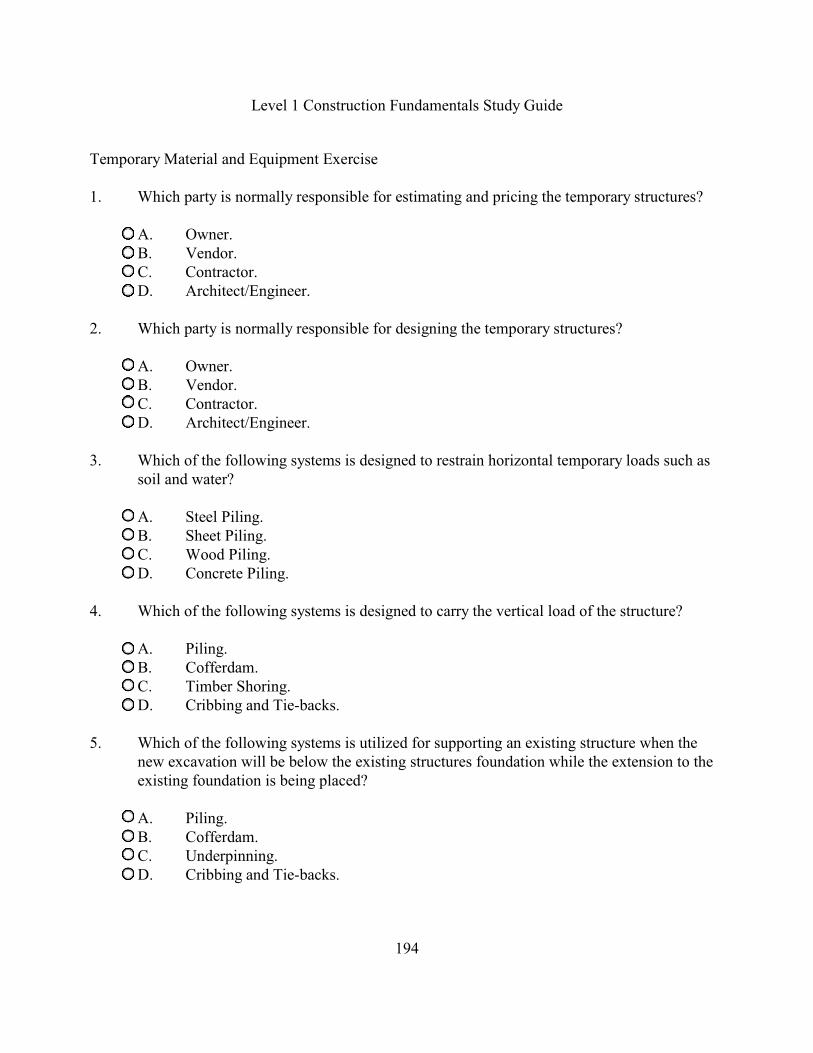
Temporary Material and Equipment Exercise
1. Which party is normally responsible for estimating and pricing the temporary structures?
A. Owner.B. Vendor.C. Contractor.D. Architect/Engineer.
2. Which party is normally responsible for designing the temporary structures?
A. Owner.B. Vendor.C. Contractor.D. Architect/Engineer.
3. Which of the following systems is designed to restrain horizontal temporary loads such assoil and water?
A. Steel Piling.B. Sheet Piling.C. Wood Piling.D. Concrete Piling.
4. Which of the following systems is designed to carry the vertical load of the structure?
A. Piling.B. Cofferdam.C. Timber Shoring.D. Cribbing and Tie-backs.
5. Which of the following systems is utilized for supporting an existing structure when thenew excavation will be below the existing structures foundation while the extension to theexisting foundation is being placed?
A. Piling. B. Cofferdam.C. Underpinning.D. Cribbing and Tie-backs.
Level 1 Construction Fundamentals Study Guide
195
Temporary Material and Equipment Exercise
6. Which of the following systems is utilized for restraining a vertical wall of soil and otherloads where it is impractical to slope the soil such as in a downtown area where theexcavation and new substructure are below the street level?
A. Piling. B. Cofferdam.C. Underpinning.D. Cribbing and Tie-backs.
7. Which of the following systems is designed as an enclosed structure to restrain soil andwater, therefore, allowing workers to work inside safely?
A. Caisson.B. Jin Poles.C. Cofferdam.D. Underpinning.
8. In construction, what is the proper terminology for transporting the off road equipment tothe job site?
A. Hauling.B. Mobilization.C. Militarization.D. Transportation.
9. What is the lifting system called which consists of two vertical towers with a cross beam ontop with the intended purpose of lifting an unusually long piece of equipment which wastransported horizontally and it is lifted into its permanent vertical position?
A. Caisson.B. Jin Pole.C. Cofferdam.D. Tower Crane.

Level 1 Construction Fundamentals Study Guide
196
Temporary Material and Equipment Exercise
10. What are the components of a cofferdam or a support system?
A. Sheeting, Wales, and Cross braces.B. Posts, Stringers, Joists and Pans.C. Posts, Stringers, Joists and Plyform.D. Wall forms, Wall Ties, Wales, Hairpins and Braces.
11. What is a toe in relationship to a Cofferdam?
A. The Tie Back extension beyond the Cribbing at least 2 feet.B. The horizontal Wales which extends beyond the wall at least 2 feet.C. The braces set at a 45-degree angle and extended into the ground at least 2 feet.D. The vertical sheeting extended below the bottom of the excavation at least 2 feet.
12. According to the OSHA Construction Safety Standards, what is required for shoringsystems more than 20 feet deep?
A. The Architect shall design the protection system.B. The Project Engineer shall design the protection system.C. The designated Competent Person shall design the protection system.D. The Registered Professional Engineer shall design the protection system.
13. What is another name for Sheeting?
A. Piles.B. Struts.C. Uprights.D. Caissons.
14. What does “close sheeting” mean in relationship to a shoring system?
A. The span across the width of an excavation.B. The spacing between timber planks not to exceed ½ inch.C. Tongue and groove timber planks at least 3 inches thick.D. The use of a trench box or trench shield while working in the excavation.
Level 1 Construction Fundamentals Study Guide
197
Temporary Material and Equipment Exercise
15. Which piece of equipment and attachment would be the most efficient method to excavateinside a cofferdam?
A. Shovel with a 3-CY bucket.B. Backhoe with a 3-CY bucket.C. Crane with an Auger Attachment.D. Crane with a Clamshell attachment.
16. Which piece of equipment sets below the excavation and the bucket pushes up?
A. Power Shovel.B. Hydraulic Backhoe.C. Dragline.D. Wheel-tractor Scraper.
17. Which piece of equipment is used to excavate ponds or soil under water?
A. Shovel.B. Backhoe.C. Dragline.D. Wheel-tractor Scraper.
18. Which piece of equipment has its boom above the structure and it lifts the load verticallyuntil it is above the structure, then it can move the load horizontally?
A. Shovel.B. Backhoe.C. Tower Crane.D. Track-mounted Crane.
19. Which piece of equipment is most efficient for compacting granular soils such as sand,gravel, and crushed stone?
A. Backhoe.B. Sheepsfoot.C. Smooth-Wheel Roller.D. Wheel-tractor scraper.

Level 1 Construction Fundamentals Study Guide
198
Temporary Material and Equipment Exercise
20. Which of the following temporary systems is utilized to support freshly placed concretewhich is poured continuously in a vertical direction?
A. Slip form system.B. Tilt-up for system.C. Flying form system.D. Lift slab form system.
21. Which of the following temporary systems is utilized to support freshly placed concretewhich is poured on the ground as a slab and lifted up to its final horizontal elevation usinghydraulic jacks?
A. Slip form system.B. Tilt-up for system.C. Flying form system.D. Lift slab form system.
22. What is the concrete pouring method called that is used to pour concrete under water?
A. Tremie.B. Conveyor.C. Direct Chute.D. Underpinning.
23. Which organization has published a new design standard targeting loads on structuresduring construction?
A. American Concrete Institute.B. Concrete Reinforcing Steel Institute.C. American Society for Testing Materials.D. Structural Engineering Institute of the American Society of Civil Engineers.
24. What is the primary cause for a masonry wall to collapse while under construction?
A. Poor soil conditions.B. Lack of vertical reinforcement.C. Lack of horizontal reinforcement.D. Lack of masonry wall bracing and a change in wind conditions.

Level 1 Construction Fundamentals Study Guide
199
Temporary Material and Equipment Exercise
25. Which of the following sling angle ranges is best for lifting without making the liftextremely dangerous?
A. 1 degree to 14 degrees.B. 15 degrees to 30 degrees.C. 31 degrees to 44 degrees.D. 45 degrees to 90 degrees.
26. You have an assumed sling angle of 24 degrees but the actual angel is 19 degrees. Whateffect does this have on the pounds per leg on the sling?
A. The pounds per leg will decrease.B. The pounds per leg will increase.C. The pounds per leg stays constant.D. The pounds per leg does not matter since the cranes lifting capacity is not effected
Using the Working Range of a Crane Chart attached, answer questions 27 through 33.
27. What is the working range of a Clam Shell?
A. 00 - 24 degreesB. 25 - 39 degreesC. 40 - 54 degreesD. 55 - 80 degrees
28. What is the working range of a Lift Crane?
A. 00 - 24 degreesB. 25 - 39 degreesC. 40 - 54 degreesD. 55 - 80 degrees
29. What is the working range of a Dragline?
A. 00 - 24 degreesB. 25 - 39 degreesC. 40 - 54 degreesD. 55 - 80 degrees
Level 1 Construction Fundamentals Study Guide
200
Temporary Material and Equipment Exercise
30. Assume you are lifting an item onto the roof. The Height of the exterior wall is 27 Feetabove the ground and the horizontal distance from the centerline of the rotation is 40 feet.What is the minimum length of the boom required?
A. 20 Feet.B. 50 Feet.C. 60 Feet.D. 70 Feet.
31. Assume you are lifting an item onto the bridge deck. The Deck is 27 feet above the groundand the horizontal distance from the centerline of the rotation is 40 feet. What is theminimum boom angle?
A. 30 degrees.B. 40 degrees.C. 57 degrees.D. 72 degrees.
32. Assume you are lifting an item onto the bridge deck. The deck is 37 feet above the groundand the horizontal distance from the centerline of the rotation is 70 feet. What is theminimum length of the boom required?
A. 70 Feet.B. 87 Feet.C. 110 Feet.D. 120 Feet.
33. Assume you are lifting an item onto the bridge deck. The deck is 37 feet above the groundand the horizontal distance from the centerline of the rotation is 70 feet. What is theminimum boom angle?
A. 26 degrees.B. 40 degrees.C. 47 degrees.D. 57 degrees.
Level 1 Construction Fundamentals Study Guide
201
Schedules on Plans and in the Technical SpecificationMany of the CSI Divisions utilize schedules to represent the work. Therefore, it is essential that aConstructor be able to identify and interpret information from various schedules as well as fromthe technical specifications and the plans. Some of the most common schedules, constructionspecifications and plans from various divisions will be discussed below.
Concrete Beam Schedule for Division 03 - ConcreteThe Concrete Reinforcing Steel Institute (CRSI) defines reinforced concrete as a combination ofboth reinforcing steel and concrete using the best properties of each. They take into considerationthe compression properties of the concrete and the tension strength of reinforcing steel.
The Reinforcing Steel Bars are also referred to as deformed bars. Reinforcing steel is mostcommon in the form of deformed bars which contains ridges which makes a good bond with theconcrete instead of smooth reinforcing. Each reinforcing bar contains identifying marks. Theuppermost designation is usually a letter identifying the manufacturer, the next mark the bar sizesuch as a #11. The bar numbers designate eighths of an inch beginning with a No. 3. The rebardiameter is determined by taking the bar # and dividing by eight. Therefore, a #3 bar is 3/8 inch indiameter. A #4 bar is 4/8 or ½ inch. The third mark down is type of steel used. Reinforcing bars aremade of either new billet, axle, or rail steel. The fourth identifying mark may be shown on the baris the tensile yield point. The tensile yield point indicates the minimum pounds per square inch(psi). A grade of 40 reinforcing bar has a minimum yield of 40,000 psi. Other grades are 50 and 60.
Welded Wire Fabric (WWF) is used in slabs-on-grade and highways. It is made of wire generallyarranged to cross at right angles at each intersection. The welded wire fabric is made and deliveredin rolls or as sheets. The designation is 6 x 6 - W1.4 x W1.4 (10 x 10). The 6 x 6 means that thespacing is 6 inches by 6 inches and the W1.4 xW1.4 is the wire (number) size for a 10-gaugematerial. The parenthesis indicates the old designation indicating the wire gauge.
Bar supports are normally incorporated by reference and they are not shown on the plans. It is theContractors responsibility to ensure that they are placed properly. This requires the contractor toreview the CRSI 65 Recommended Practice for Placing Bar Supports, Specifications andNomenclature. Typically they are designed to raise the reinforcing bars to the required heightabove the bottom of the forms and to hold the bars in place. Many times bar supports are placed inthe upper third of the slab and the lower third of the slab. This requires two sets of bar supportsplaced in a slab or beam. Normally these bar supports are called slab bolsters and beam bolstersand if their location is in the upper third of the slab or beam, then a U is placed at the end of theabbreviation. For example, BB means Beam Bolster and BBU means Beam Bolster Upper. TheConcrete Reinforcing Steel Institute (CRSI) publication titled, Manual of Standard Practice andthe adapted table titled Bar Support Designations is shown below.

Level 1 Construction Fundamentals Study Guide
202
The CSI Master Format has the bar supports under Division 03 CONCRETE, Section 200REINFORCEMENT and Part 1.03 REFERENCE STANDARDS. A typical specification wouldindicate that the Contractor must be in compliance with CRSI 65 Recommended Practice forPlacing Bar Supports, Specifications and Nomenclature. CRSI is an abbreviation for the ConcreteReinforcing Steel Institute. Some of the typical Types and Sizes of Wire Bar Support with theirabbreviations, the type of support and the typical sizes are identified below.
SYMBOL TYPE OF SUPPORT TYPICAL HEIGHTS
SB Slab Bolster 3/4, 1, 1-1/2, 2 inches
SBU Slab Bolster Upper Same as SB
BB Beam Bolster 1,1-1/2, 2 to 5 inches in 1/4" increments
BBU Beam Bolster Upper Same as BB
BC Individual Bar Chair 3/4, 1, 1-1/2 and 1-3/4 inches
JC Joist Chair 3/4, 1, and 1-1/2 and 4, 5, 6 inches in widths
HC Individual High Chair 2 to 15 inches in 1/4" increments
HCM High Chair for Metal Decking 2 to 15 inches in 1/4" increments
CHC Continuous High Chair Same as HC
CHCU Continuous High Chair Upper Same as CHC
JCU Joist Chair Upper Heights -1 thru +3-1/2 in; 14 inch span
Adapted from the Concrete Reinforcing Steel Institute (March 2001). Manual of Standard Practice. Schaumburg, IL:
author.
Column, Beam and Slab SchedulesAre utilized to provide the Constructor with detailed information for placing the reinforcing bars,the stirrups, and the bar supports. Reinforcing bars are designated as either straight bars or barbends which are fabricated by the manufacturer in the shop and shipped to the job site.
Stirrups are also known as ties and they are used to wrap the around the horizontal or vertical barsat specified on center spacings. A Beam schedule is provided below as an exercise.
Level 1 Construction Fundamentals Study Guide
203
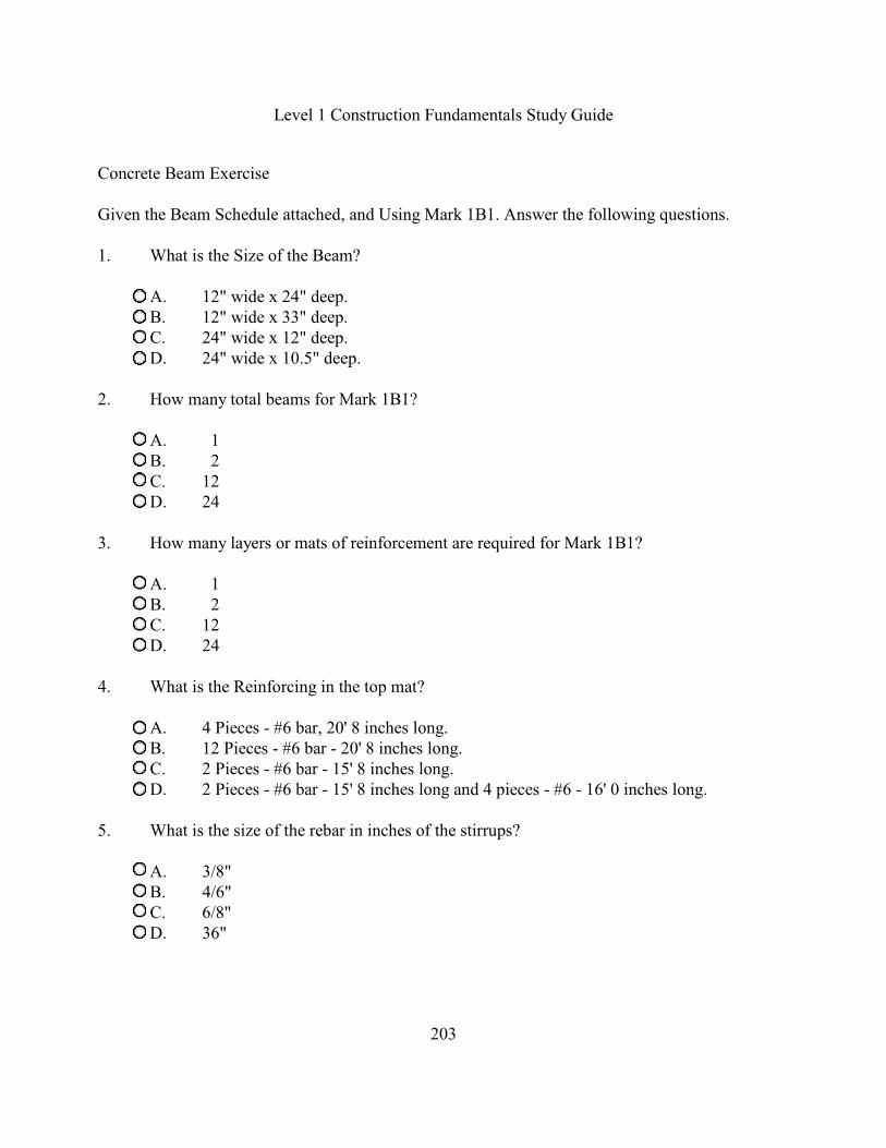
Concrete Beam Exercise
Given the Beam Schedule attached, and Using Mark 1B1. Answer the following questions.
1. What is the Size of the Beam?
A. 12" wide x 24" deep.B. 12" wide x 33" deep.C. 24" wide x 12" deep.D. 24" wide x 10.5" deep.
2. How many total beams for Mark 1B1?
A. 1B. 2C. 12D. 24
3. How many layers or mats of reinforcement are required for Mark 1B1?
A. 1B. 2C. 12D. 24
4. What is the Reinforcing in the top mat?
A. 4 Pieces - #6 bar, 20' 8 inches long.B. 12 Pieces - #6 bar - 20' 8 inches long.C. 2 Pieces - #6 bar - 15' 8 inches long.D. 2 Pieces - #6 bar - 15' 8 inches long and 4 pieces - #6 - 16' 0 inches long.
5. What is the size of the rebar in inches of the stirrups?
A. 3/8"B. 4/6"C. 6/8"D. 36"
Level 1 Construction Fundamentals Study Guide
204
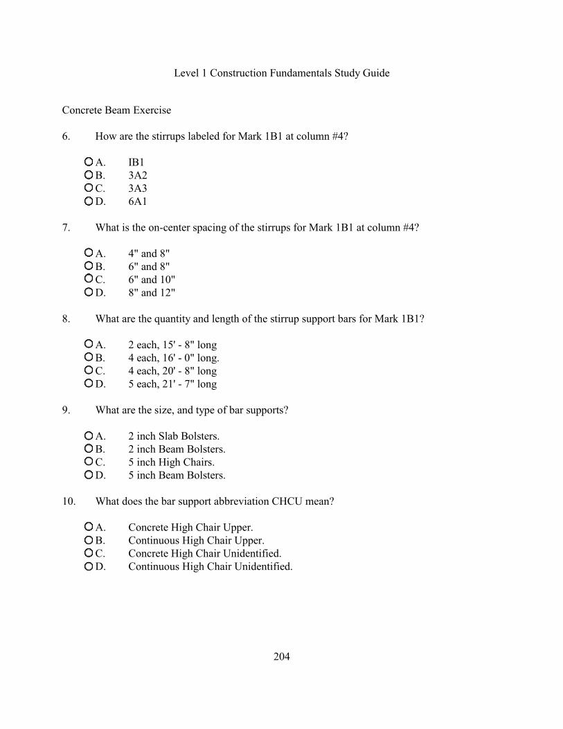
Concrete Beam Exercise
6. How are the stirrups labeled for Mark 1B1 at column #4?
A. IB1B. 3A2C. 3A3D. 6A1
7. What is the on-center spacing of the stirrups for Mark 1B1 at column #4?
A. 4" and 8"B. 6" and 8"C. 6" and 10"D. 8" and 12"
8. What are the quantity and length of the stirrup support bars for Mark 1B1?
A. 2 each, 15' - 8" longB. 4 each, 16' - 0" long.C. 4 each, 20' - 8" longD. 5 each, 21' - 7" long
9. What are the size, and type of bar supports?
A. 2 inch Slab Bolsters.B. 2 inch Beam Bolsters.C. 5 inch High Chairs.D. 5 inch Beam Bolsters.
10. What does the bar support abbreviation CHCU mean?
A. Concrete High Chair Upper.B. Continuous High Chair Upper.C. Concrete High Chair Unidentified.D. Continuous High Chair Unidentified.

Level 1 Construction Fundamentals Study Guide
205
Concrete Beam Exercise
11. What does the bar support abbreviation BBU mean?
A. Broad Beam Upper.B. Beam Bolster Upper.C. Bottom Bar Unidentified.D. Beam Bolster Unidentified.
12. What does the bar support abbreviation SB?
A. Slab Bar.B. Slab Bolster.C. Slab Bottom.D. Beam Bolster.
13. Which of the following items are not shown or specified in the construction documents fora reinforced concrete structure?
A. Rebar.B. Concrete.C. Bar Supports.D. Welded Wire Mesh.
14. What is the name of the organization which publishes a manual on the spacingrequirements for bar supports?
A. American Concrete Institute.B. Concrete Reinforcing Steel Institute.C. Concrete Reinforcement Standards Institute.D. Concrete Reinforcing Specifications Institute.
Level 1 Construction Fundamentals Study Guide
206
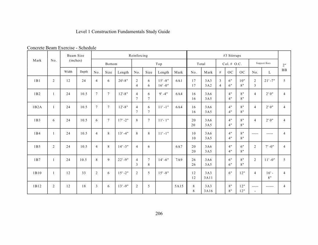
Concrete Beam Exercise - Schedule
Mark No.
Beam Size
(inches)
Reinforcing #3 Stirrups
2"
BB
Bottom Top Total Col. # O.C. Support Bars
Width Depth No. Size Length No. Size Length Mark No. Mark # OC OC No. L
1B1 2 12 24 4 6 20'-8" 2
4
6
6
15' -8"
16' -0"
6A1 17
17
3A3
3A2
3
4
6"
6"
10"
8"
2
3
21' -7" 5
1B2 1 24 10.5 7 7 12'-8" 4
7
6
7
9' -4" 6A4 16
16
3A6
3A5
4"
4"
8"
8"
4 2' 0" 4
1B2A 1 24 10.5 7 7 12'-8" 4
7
6
7
11' -1" 6A4 16
16
3A6
3A5
4"
4"
8"
8"
4 2' 0" 4
1B3 6 24 10.5 6 7 17' -2" 8 7 11'- 1" 20
20
3A6
3A5
4"
4"
8"
8"
4 2' 0" 4
1B4 1 24 10.5 4 8 13' -4" 8 8 11' -1" 10
10
3A6
3A5
4"
4"
8"
8"
----- ----- 4
1B5 2 24 10.5 4 8 14' -3" 4 6 6A7 20
20
3A6
3A5
4"
4"
6"
8"
2 7' -0" 4
1B7 1 24 10.5 8 9 22' -9" 4
3
7
8
14' -6" 7A9 26
26
3A6
3A5
6"
6"
8"
8"
2 11' -0" 5
1B10 1 12 33 2 6 15' -2" 2 5 15' -8" 12
12
3A3
3A11
6" 12" 4 16' -
8"
4
1B12 2 12 18 3 6 13' -9" 2 5 5A15 8
8
3A3
3A16
8"
8"
12"
12"
-----
-
------ 4
Level 1 Construction Fundamentals Study Guide
207
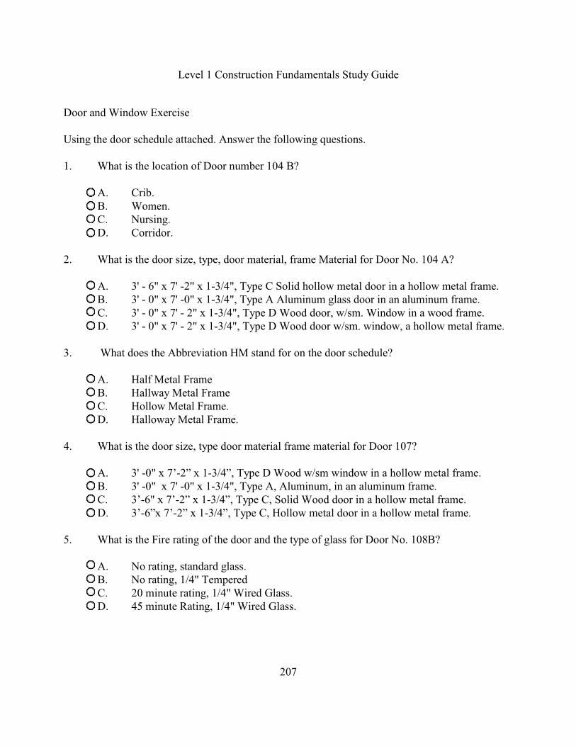
Door and Window Exercise
Using the door schedule attached. Answer the following questions.
1. What is the location of Door number 104 B?
A. Crib.B. Women.C. Nursing.D. Corridor.
2. What is the door size, type, door material, frame Material for Door No. 104 A?
A. 3' - 6" x 7' -2" x 1-3/4", Type C Solid hollow metal door in a hollow metal frame.B. 3' - 0" x 7' -0" x 1-3/4", Type A Aluminum glass door in an aluminum frame.C. 3' - 0" x 7' - 2" x 1-3/4", Type D Wood door, w/sm. Window in a wood frame.D. 3' - 0" x 7' - 2" x 1-3/4", Type D Wood door w/sm. window, a hollow metal frame.
3. What does the Abbreviation HM stand for on the door schedule?
A. Half Metal FrameB. Hallway Metal FrameC. Hollow Metal Frame.D. Halloway Metal Frame.
4. What is the door size, type door material frame material for Door 107?
A. 3' -0" x 7’-2” x 1-3/4”, Type D Wood w/sm window in a hollow metal frame.B. 3' -0" x 7' -0" x 1-3/4", Type A, Aluminum, in an aluminum frame.C. 3’-6" x 7’-2” x 1-3/4”, Type C, Solid Wood door in a hollow metal frame.D. 3’-6”x 7’-2” x 1-3/4”, Type C, Hollow metal door in a hollow metal frame.
5. What is the Fire rating of the door and the type of glass for Door No. 108B?
A. No rating, standard glass.B. No rating, 1/4" TemperedC. 20 minute rating, 1/4" Wired Glass.D. 45 minute Rating, 1/4" Wired Glass.
Level 1 Construction Fundamentals Study Guide
208
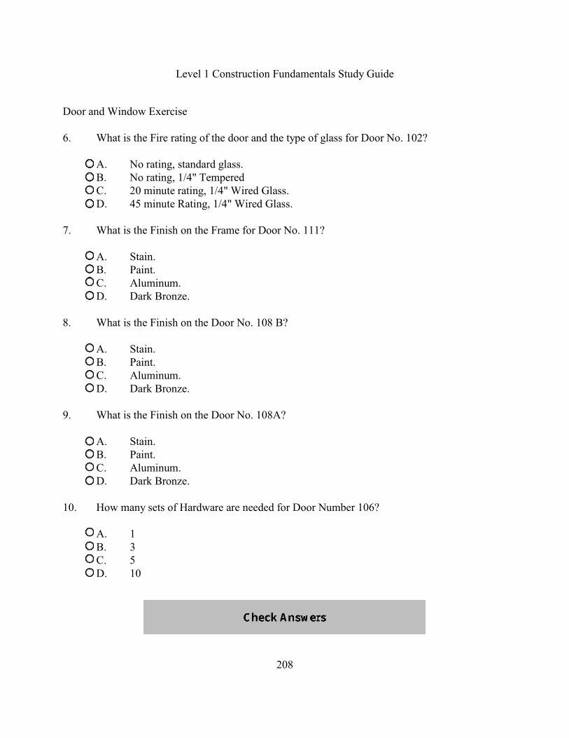
Door and Window Exercise
6. What is the Fire rating of the door and the type of glass for Door No. 102?
A. No rating, standard glass.B. No rating, 1/4" TemperedC. 20 minute rating, 1/4" Wired Glass.D. 45 minute Rating, 1/4" Wired Glass.
7. What is the Finish on the Frame for Door No. 111?
A. Stain.B. Paint.C. Aluminum.D. Dark Bronze.
8. What is the Finish on the Door No. 108 B?
A. Stain.B. Paint.C. Aluminum.D. Dark Bronze.
9. What is the Finish on the Door No. 108A?
A. Stain.B. Paint.C. Aluminum.D. Dark Bronze.
10. How many sets of Hardware are needed for Door Number 106?
A. 1B. 3C. 5D. 10
Level 1 Construction Fundamentals Study Guide
209
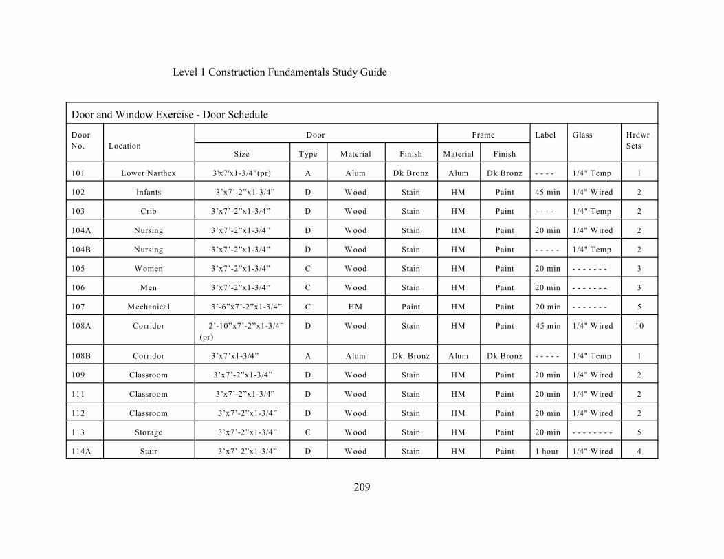
Door and Window Exercise - Door Schedule
Door
No. Location
Door Frame Label Glass Hrdwr
SetsSize Type Material Finish Material Finish
101 Lower Narthex 3'x7'x1-3/4"(pr) A Alum Dk Bronz Alum Dk Bronz - - - - 1/4" Temp 1
102 Infants 3’x7’-2”x1-3/4” D Wood Stain HM Paint 45 min 1/4" Wired 2
103 Crib 3’x7’-2”x1-3/4” D Wood Stain HM Paint - - - - 1/4" Temp 2
104A Nursing 3’x7’-2”x1-3/4” D Wood Stain HM Paint 20 min 1/4" Wired 2
104B Nursing 3’x7’-2”x1-3/4” D Wood Stain HM Paint - - - - - 1/4" Temp 2
105 Women 3’x7’-2”x1-3/4” C Wood Stain HM Paint 20 min - - - - - - - 3
106 Men 3’x7’-2”x1-3/4” C Wood Stain HM Paint 20 min - - - - - - - 3
107 Mechanical 3’-6”x7’-2”x1-3/4” C HM Paint HM Paint 20 min - - - - - - - 5
108A Corridor 2’-10”x7’-2”x1-3/4”
(pr)
D Wood Stain HM Paint 45 min 1/4" Wired 10
108B Corridor 3’x7’x1-3/4” A Alum Dk. Bronz Alum Dk Bronz - - - - - 1/4" Temp 1
109 Classroom 3’x7’-2”x1-3/4” D Wood Stain HM Paint 20 min 1/4" Wired 2
111 Classroom 3’x7’-2”x1-3/4” D Wood Stain HM Paint 20 min 1/4" Wired 2
112 Classroom 3’x7’-2”x1-3/4” D Wood Stain HM Paint 20 min 1/4" Wired 2
113 Storage 3’x7’-2”x1-3/4” C Wood Stain HM Paint 20 min - - - - - - - - 5
114A Stair 3’x7’-2”x1-3/4” D Wood Stain HM Paint 1 hour 1/4" Wired 4

Level 1 Construction Fundamentals Study Guide
210
Door and Window Exercise - Diagrams

Level 1 Construction Fundamentals Study Guide
211
Finish and Paint Exercise
Using the Room Schedule attached, answer the following questions.
1. In room no. 105, which materials will be utilized on the floor?
A. Vinyl.B. Concrete.C. Carpet #1.D. Carpet #2.
2. In Room No. 201, which material and finish will be on the W/NW Wall?
A. CMU and paint.B. SF CMU, unpainted.C. SF CMU/Wood, stain.D. SF CMU/Wood, unpainted.
3. What does the abbreviation CMU on the Room Finish Schedule mean?
A. Cast Metal Unit.B. Cabinet Metal Unit.C. Corrugated Metal Unit.D. Concrete Masonry Unit.
4. What is the height of the ceiling in room No. 107?
A. 8' - 0"B. 9' - 0"C. 10' - 3"D. 13' - 0"
5. What are the ceiling material and finish in room No. 132?
A. ACT #1 and paint.B. SF CMU and no paint.C. ACT #1 and no paint.D. Gypsum board and paint.
Level 1 Construction Fundamentals Study Guide
212
Finish and Paint Exercise
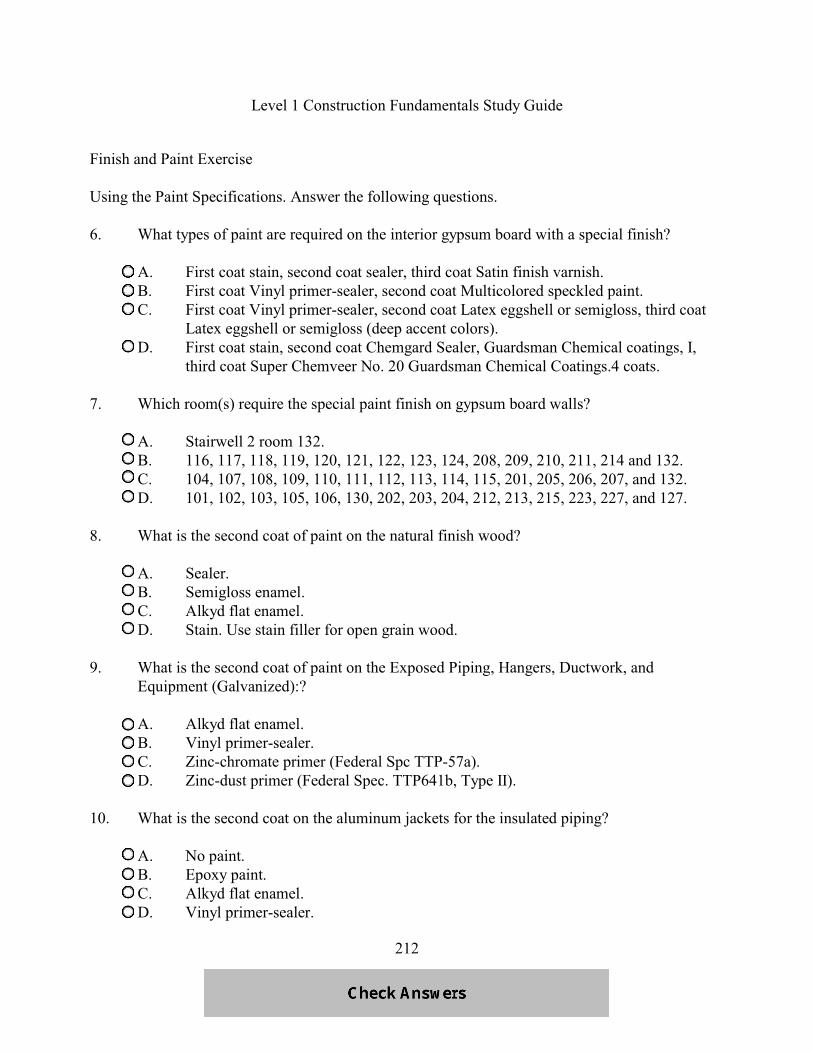
Using the Paint Specifications. Answer the following questions.
6. What types of paint are required on the interior gypsum board with a special finish?
A. First coat stain, second coat sealer, third coat Satin finish varnish.B. First coat Vinyl primer-sealer, second coat Multicolored speckled paint.C. First coat Vinyl primer-sealer, second coat Latex eggshell or semigloss, third coat
Latex eggshell or semigloss (deep accent colors).D. First coat stain, second coat Chemgard Sealer, Guardsman Chemical coatings, I,
third coat Super Chemveer No. 20 Guardsman Chemical Coatings.4 coats.
7. Which room(s) require the special paint finish on gypsum board walls?
A. Stairwell 2 room 132.B. 116, 117, 118, 119, 120, 121, 122, 123, 124, 208, 209, 210, 211, 214 and 132.C. 104, 107, 108, 109, 110, 111, 112, 113, 114, 115, 201, 205, 206, 207, and 132.D. 101, 102, 103, 105, 106, 130, 202, 203, 204, 212, 213, 215, 223, 227, and 127.
8. What is the second coat of paint on the natural finish wood?
A. Sealer.B. Semigloss enamel.C. Alkyd flat enamel.D. Stain. Use stain filler for open grain wood.
9. What is the second coat of paint on the Exposed Piping, Hangers, Ductwork, andEquipment (Galvanized):?
A. Alkyd flat enamel.B. Vinyl primer-sealer.C. Zinc-chromate primer (Federal Spc TTP-57a).D. Zinc-dust primer (Federal Spec. TTP641b, Type II).
10. What is the second coat on the aluminum jackets for the insulated piping?
A. No paint.B. Epoxy paint.C. Alkyd flat enamel.D. Vinyl primer-sealer.

Level 1 Construction Fundamentals Study Guide
213
Finish and Paint Exercise - Room Finish Schedule
Rm.
No
Room
Name
Floor N/NE & S/SW E/SE Wall W/NW Wall Ceiling
Material Base Material Finish Material Finish Material Finish Material Finish HT
101 Lower Narthex Carpet #1 Carpet #1 CMU Paint CMU Paint CMU Paint ACT #1 9' -0"
102 Infants Carpet #2 Carpet #2 CMU Paint CMU Paint CMU Paint ACT #2 8' -0"
103 Crib Carpet #2 Carpet #2 CMU Paint CMU Paint CMU Paint ACT #2 8' -0"
104 Nursing Carpet #2 Carpet #2 CMU Paint CMU Paint CMU Paint ACT #2 8' -0"
105 Women Vinyl Vinyl CMU Paint CMU Paint CMU Paint Gyp Bd Paint 8' -0"
106 Men Vinyl Vinyl CMU Paint CMU Paint CMU Paint Gyp Bd Paint 8' -0"
107 Mechanical Concrete - - - - - - - CMU Paint CMU Paint CMU Paint Exposed Paint 10'-3"
127 Stair Carpet #1 Carpet #1 Glass - - -- - SP CMU - - - - Glass - - - ACT #1 - - - -
132 Stair Carpet #1 Carpet #1 SF CMU - - - - - SF CMU - - - - SF CMU - - - ACT #1 8' -0"
201 Narthex A Carpet #1 Carpet #1 Glass
SF CMU
- -/ - - SF CMU - - - - SF CMU/
Wood
- / Stain ACT #1 13'-0"
206 Narthex B Carpet #1 Carpet #1 SF CMU - - - - - SF CMU - - - - SF CMU - - - - ACT #1 13'-0"
Abbreviations
Acoustical Ceiling Tile ACT Concrete Masonry Unit CMU Gypsum Board Gyp Bd
Split Face cmu SF Specified cmu SP Vinyl Composite Tile VCT
Level 1 Construction Fundamentals Study Guide
214
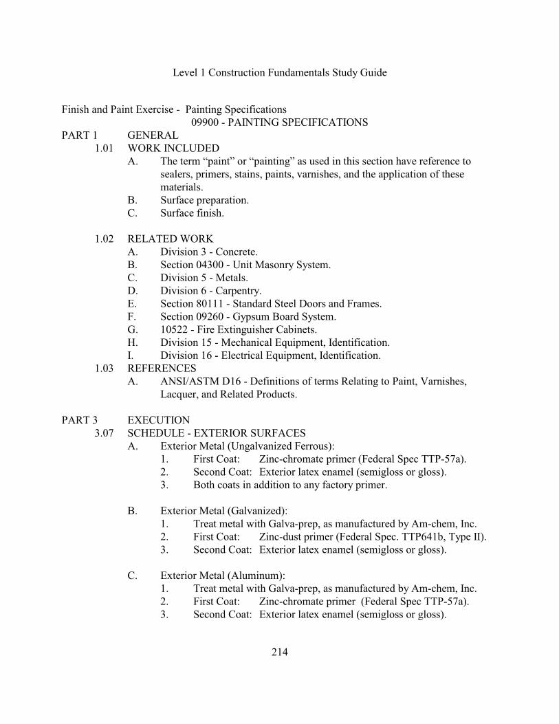
Finish and Paint Exercise - Painting Specifications09900 - PAINTING SPECIFICATIONS
PART 1 GENERAL1.01 WORK INCLUDED
A. The term “paint” or “painting” as used in this section have reference tosealers, primers, stains, paints, varnishes, and the application of thesematerials.
B. Surface preparation.C. Surface finish.
1.02 RELATED WORKA. Division 3 - Concrete.B. Section 04300 - Unit Masonry System.C. Division 5 - Metals.D. Division 6 - Carpentry.E. Section 80111 - Standard Steel Doors and Frames.F. Section 09260 - Gypsum Board System.G. 10522 - Fire Extinguisher Cabinets.H. Division 15 - Mechanical Equipment, Identification.I. Division 16 - Electrical Equipment, Identification.
1.03 REFERENCESA. ANSI/ASTM D16 - Definitions of terms Relating to Paint, Varnishes,
Lacquer, and Related Products.
PART 3 EXECUTION3.07 SCHEDULE - EXTERIOR SURFACES
A. Exterior Metal (Ungalvanized Ferrous):1. First Coat: Zinc-chromate primer (Federal Spec TTP-57a).2. Second Coat: Exterior latex enamel (semigloss or gloss).3. Both coats in addition to any factory primer.
B. Exterior Metal (Galvanized):1. Treat metal with Galva-prep, as manufactured by Am-chem, Inc.2. First Coat: Zinc-dust primer (Federal Spec. TTP641b, Type II).3. Second Coat: Exterior latex enamel (semigloss or gloss).
C. Exterior Metal (Aluminum):1. Treat metal with Galva-prep, as manufactured by Am-chem, Inc.2. First Coat: Zinc-chromate primer (Federal Spec TTP-57a).3. Second Coat: Exterior latex enamel (semigloss or gloss).
Level 1 Construction Fundamentals Study Guide
215
Finish and Paint Exercise - Painting Specifications
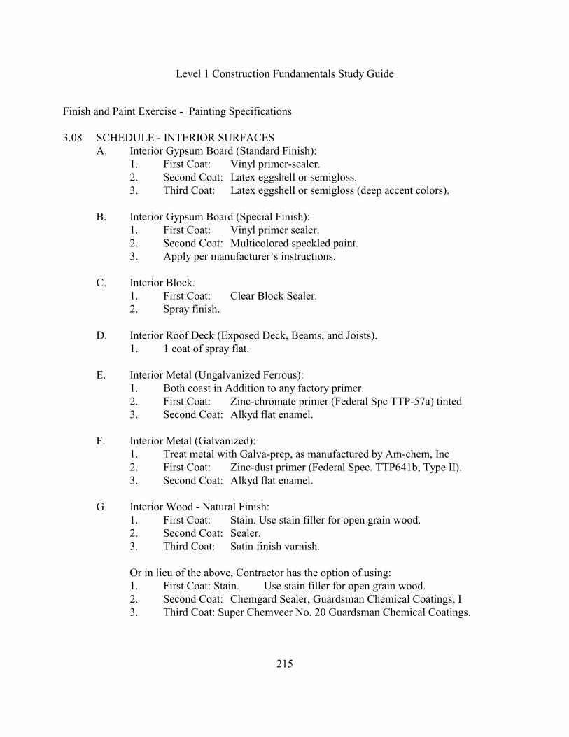
3.08 SCHEDULE - INTERIOR SURFACESA. Interior Gypsum Board (Standard Finish):
1. First Coat: Vinyl primer-sealer.2. Second Coat: Latex eggshell or semigloss.3. Third Coat: Latex eggshell or semigloss (deep accent colors).
B. Interior Gypsum Board (Special Finish):1. First Coat: Vinyl primer sealer.2. Second Coat: Multicolored speckled paint.3. Apply per manufacturer’s instructions.
C. Interior Block.1. First Coat: Clear Block Sealer.2. Spray finish.
D. Interior Roof Deck (Exposed Deck, Beams, and Joists).1. 1 coat of spray flat.
E. Interior Metal (Ungalvanized Ferrous):1. Both coast in Addition to any factory primer.2. First Coat: Zinc-chromate primer (Federal Spc TTP-57a) tinted3. Second Coat: Alkyd flat enamel.
F. Interior Metal (Galvanized):1. Treat metal with Galva-prep, as manufactured by Am-chem, Inc2. First Coat: Zinc-dust primer (Federal Spec. TTP641b, Type II).3. Second Coat: Alkyd flat enamel.
G. Interior Wood - Natural Finish:1. First Coat: Stain. Use stain filler for open grain wood.2. Second Coat: Sealer.3. Third Coat: Satin finish varnish.
Or in lieu of the above, Contractor has the option of using:1. First Coat: Stain. Use stain filler for open grain wood.2. Second Coat: Chemgard Sealer, Guardsman Chemical Coatings, I3. Third Coat: Super Chemveer No. 20 Guardsman Chemical Coatings.

Level 1 Construction Fundamentals Study Guide
216
Finish and Paint Exercise - Painting Specifications
H. Interior Wood Painted:1. First Coat: Wood primer undercoater.2. Second Coat: Semigloss enamel.3. Third Coat: Semigloss enamel.
I. Exposed Piping, Hangers, and Equipment (Ungalvanized):1. First Coat: Zinc-chromate primer (Federal Spc TTP-57a)2. Second Coat: Alkyd flat enamel. 3. Note: Cast iron pipe shall first be throughly cleaned with rags soaked in
mineral spirits to remove oily film, then primed and finished as indicatedabove.
J. Exposed Piping, Hangers, Ductwork, and Equipment (Galvanized):1. Treat metal with Galva-prep, as manufactured by Am-chem, Inc2. First Coat: Zinc-dust primer (Federal Spec. TTP641b, Type II).3. Second Coat: Alkyd flat enamel.4. Note: Use epoxy paint for PVC pipe.
K. Covered (Insulated) Piping and Ductwork (Unprimed):1. First Coat: Vinyl primer-sealer.2. Second Coat: Alkyd flat enamel.3. Note: Aluminum jackets for insulated piping shall not be painted
L. Back Priming (Interior Millwork and Trim):1. 1 coat of white oil base primer for wood to receive paint finish.2. Clear sealer for wood to receive natural finish.3. Back prime interior millwork on unexposed areas as specified in Div.6.
M. Apply special paint finish on gypsum board walls in the following rooms: 101, 102,103, 105, 106, 130, 202, 203, 204, 212, 213, 215, 223, 227, and 127 (stair 1). SeeItem B above.
N. Exposed piping, hangers, ductwork, and equipment shall be painted the same coloras adjacent structure and deck.
END OF SECTION
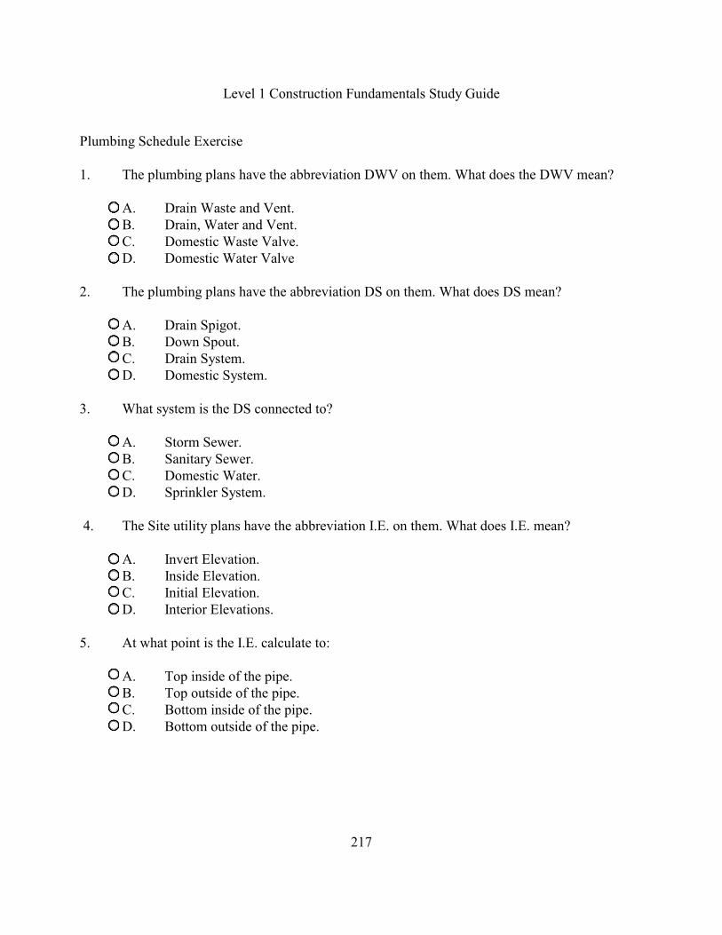
Level 1 Construction Fundamentals Study Guide
217
Plumbing Schedule Exercise
1. The plumbing plans have the abbreviation DWV on them. What does the DWV mean?
A. Drain Waste and Vent.B. Drain, Water and Vent.C. Domestic Waste Valve.D. Domestic Water Valve
2. The plumbing plans have the abbreviation DS on them. What does DS mean?
A. Drain Spigot.B. Down Spout.C. Drain System.D. Domestic System.
3. What system is the DS connected to?
A. Storm Sewer.B. Sanitary Sewer.C. Domestic Water.D. Sprinkler System.
4. The Site utility plans have the abbreviation I.E. on them. What does I.E. mean?
A. Invert Elevation.B. Inside Elevation.C. Initial Elevation.D. Interior Elevations.
5. At what point is the I.E. calculate to:
A. Top inside of the pipe. B. Top outside of the pipe. C. Bottom inside of the pipe. D. Bottom outside of the pipe.

Level 1 Construction Fundamentals Study Guide
218
Plumbing Schedule Exercise
6. What is the purpose of a water hammer arrestor?
A. Reduce the pressure in the line.B. Reduce the vibration in the line.C. Maintain a constant flow in the line.D. Maintain a constant pressure in the line.
Given the Plumbing Pipe Size Schedule and the Natatorium Plumbing Plan, Answer the followingquestions.
7. What does the plumbing abbreviation VTR mean?
A. Vent Thru Roof.B. Vent Top Return.C. Vertical Top of Roof.D. Vertical Transfer Run.
8. What system is the VTR connected to?
A. Storm Sewer.B. Sanitary Sewer.C. Domestic Water.D. Sprinkler System.
9. What system is the CO connected to?
A. Storm Sewer.B. Sanitary Sewer.C. Domestic Water.D. Sprinkler System.
10. What is the size of the connection to the HB?
A. 0"B. ½"C. 3/4"D. 1"

Level 1 Construction Fundamentals Study Guide
219
Plumbing Schedule Exercise
11. What is the size of the Domestic hot water connection to the EWC?
A. 0"B. ½"C. 3/4"D. 1"
12. What is the size of the waste line connection to the WC-2?
A. 0"B. 1"C. 2"D. 4"
13. What is the size of the cold water connection to the LAV-1?
A. 0"B. ½"C. 3/4"D. 1-1/2"
Plumbing Exercise - Pipe Size Schedule
FIXTURE COLD HOT WASTE RE
VENT
MAIN
VENT
TRAP
SIZE
REMARKS
WATER CLOSET 1" - - - 4" 2" 3" 4" FLUSH
VALVE
URINAL 3/4" - - - 2" 2" 2" 2" WALL MTD.
LAVATORY 1/2" 1/2" 1-1/2" 1-1/2" 1-1/2" 1-1/4"
SINK 1/2" 1/2" 1-1/2" 1-1/2" 2" 1-1/2" Or as Noted
ELECTRIC WATER COOLER 1/2" - - - 1-1/4" 1-1/4" - - - 1-1/4"
HOSE BIB 3/4" - - - - - - - - - - - - - - - NON-FREEZE
FLOOR DRAIN - - - - - - 3" 2" 3" 3" OR A NOTED
SERVICE SINK 3/4" 3/4" 3" 2" 2" 3"
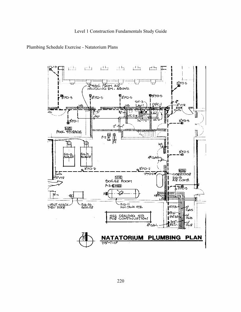
Level 1 Construction Fundamentals Study Guide
220
Plumbing Schedule Exercise - Natatorium Plans
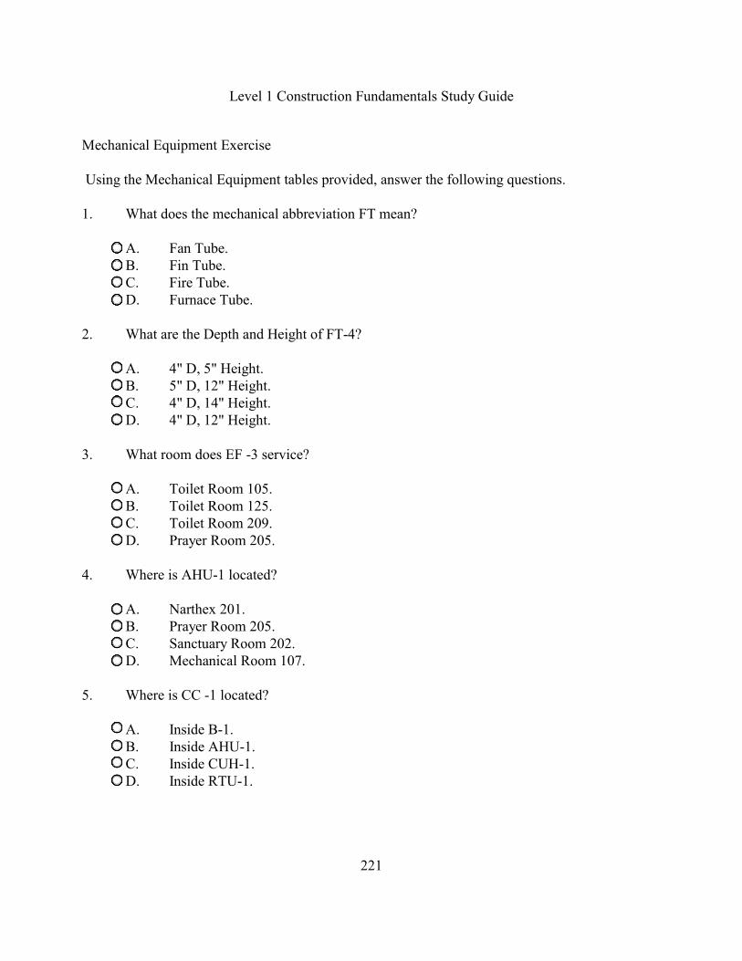
Level 1 Construction Fundamentals Study Guide
221
Mechanical Equipment Exercise
Using the Mechanical Equipment tables provided, answer the following questions.
1. What does the mechanical abbreviation FT mean?
A. Fan Tube.B. Fin Tube.C. Fire Tube.D. Furnace Tube.
2. What are the Depth and Height of FT-4?
A. 4" D, 5" Height.B. 5" D, 12" Height.C. 4" D, 14" Height.D. 4" D, 12" Height.
3. What room does EF -3 service?
A. Toilet Room 105.B. Toilet Room 125.C. Toilet Room 209.D. Prayer Room 205.
4. Where is AHU-1 located?
A. Narthex 201.B. Prayer Room 205.C. Sanctuary Room 202.D. Mechanical Room 107.
5. Where is CC -1 located?
A. Inside B-1.B. Inside AHU-1.C. Inside CUH-1.D. Inside RTU-1.
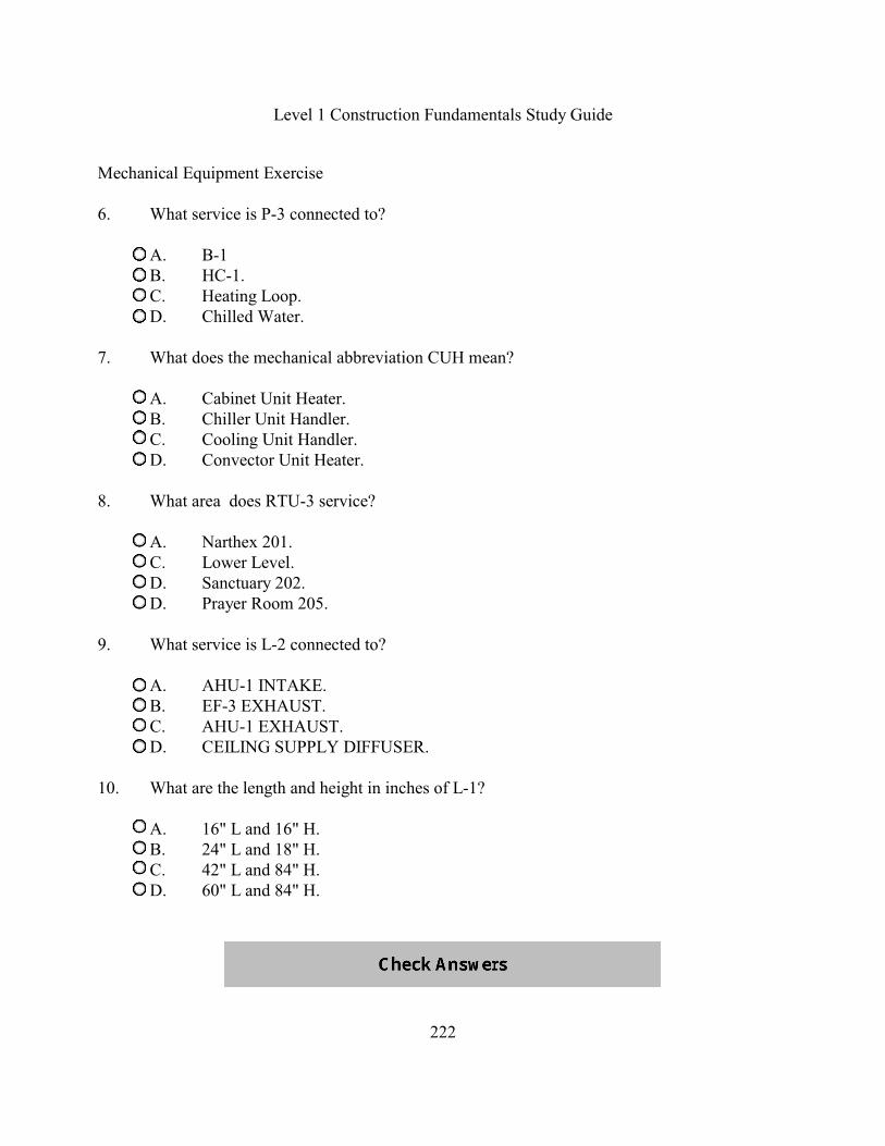
Level 1 Construction Fundamentals Study Guide
222
Mechanical Equipment Exercise
6. What service is P-3 connected to?
A. B-1B. HC-1.C. Heating Loop.D. Chilled Water.
7. What does the mechanical abbreviation CUH mean?
A. Cabinet Unit Heater.B. Chiller Unit Handler.C. Cooling Unit Handler.D. Convector Unit Heater.
8. What area does RTU-3 service?
A. Narthex 201.C. Lower Level.D. Sanctuary 202.D. Prayer Room 205.
9. What service is L-2 connected to?
A. AHU-1 INTAKE.B. EF-3 EXHAUST.C. AHU-1 EXHAUST.D. CEILING SUPPLY DIFFUSER.
10. What are the length and height in inches of L-1?
A. 16" L and 16" H.B. 24" L and 18" H.C. 42" L and 84" H.D. 60" L and 84" H.

Level 1 Construction Fundamentals Study Guide
223
Mechanical Equipment Exercise - Fan and Fin Tube Schedules
FAN SCHEDULE
Mark Service Model CFM S.P. HP/AMPS. RPM T.S./O.V. WHEEL DIA. SONES VOLTAGE
EF-1 TOILET
105,106
DB-8 825 ½” 1/4 1000 2100 ---- 9.2 120v-1PH
EF-2 TOILET
125
360 125 1/8" 1.2 1200 0000 0000 2 120V-1PH
EF-3 PRAYER
205
GN-720 500 1/4" 1/4 1325 2200 0000 3.5 120V-1PH
EF-4 TOILET
208,209
GN-820 600 1/4" 1/4 700 1600 ---- 2.3 120v-1PH
1 Based on Cook 2 Based on Broan, Provide with wall cap
FIN TUBE SCHEDULE
MARK LOCATION ELEMENT BTH/FT FIN LENGTH GPM ROWS ENCLOSURE
STYLE D. HT.
FT-1 SEE PLANS 3/4"C.-2 3/4"X3-48 720 SEE PLAN SEE PLAN 1 FS-210 4" 14"
FT-2 SEE PLANS 3/4"C-2 3/4"X3-48 720 SEE PLAN SEE PLAN 1 FS-210 4" 14"
FT-3 SEE PLANS 1"C.-3 1/4" -48 750 SEE PLAN SEE PLAN 1 AA-1r2 4" 5"
FT-4 SEE PLANS 3/4"C.-2 3/4" X 4 1/4" 1050 SEE PLAN SEE PLAN 1 DV4 5" 12"
1 BASED ON VULCAN, 180 * EWT, 160* LWT, 65* EAT 2 MOUNT INVERT AT 7'-6: A.F.F.3 PROVIDE W/ 14GA PIPE ENCLOSURE AND PRESSURE CLIP FASTENERS AT LOCATIONS SHOWN ON PLANS
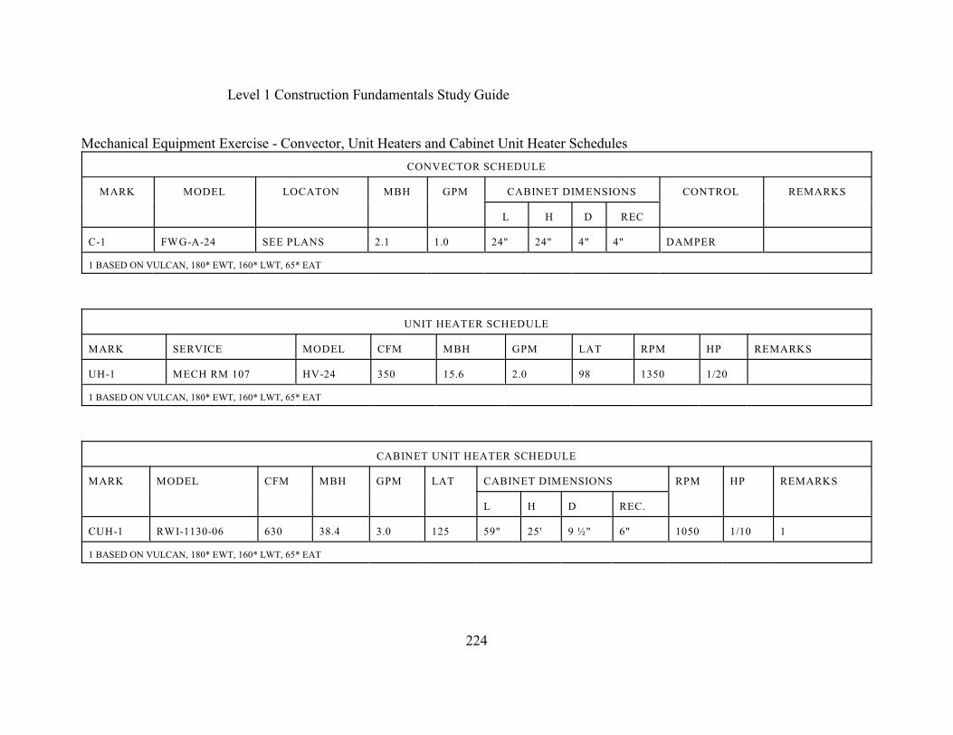
Level 1 Construction Fundamentals Study Guide
224
Mechanical Equipment Exercise - Convector, Unit Heaters and Cabinet Unit Heater Schedules
CONVECTOR SCHEDULE
MARK MODEL LOCATON MBH GPM CABINET DIMENSIONS CONTROL REMARKS
L H D REC
C-1 FWG-A-24 SEE PLANS 2.1 1.0 24" 24" 4" 4" DAMPER
1 BASED ON VULCAN, 180* EWT, 160* LWT, 65* EAT
UNIT HEATER SCHEDULE
MARK SERVICE MODEL CFM MBH GPM LAT RPM HP REMARKS
UH-1 MECH RM 107 HV-24 350 15.6 2.0 98 1350 1/20
1 BASED ON VULCAN, 180* EWT, 160* LWT, 65* EAT
CABINET UNIT HEATER SCHEDULE
MARK MODEL CFM MBH GPM LAT CABINET DIMENSIONS RPM HP REMARKS
L H D REC.
CUH-1 RWI-1130-06 630 38.4 3.0 125 59" 25' 9 ½" 6" 1050 1/10 1
1 BASED ON VULCAN, 180* EWT, 160* LWT, 65* EAT

Level 1 Construction Fundamentals Study Guide
225
Mechanical Equipment Exercise - Air Handling, Cooling Coil and Heating Coil Schedules
AIR HANDLING UNIT SCHEDULE
MARK LOCATION SERVICE MODEL CFM S.P. O.V. RPM H.P. REMARKS
EXT. TOTAL
AHU-1 MECH RM 107 LOWER LEVEL LML-122 10,100 1 1/4" 2 1/4" 1417 1291 7 ½ 1,2
1 BASED ON McQUAY2 PROVIDE 4" HIGH RAIL UNDER UNIT
COOLING COIL SCHEDULE
MK Location CFM MBH
TOT/
SEN
CHILLED WATER AIR
P.D.
WATER
P.D.
EDB EWB LDB LWB COIL
GPM LWT EWT ROWS FPF F.V.
CC-1 AHU-1 10,100 340/282 78 55* 458 .56 15.9 80* 65* 55* 54* 5 144 478 1
1 BASED ON MCQUAY
HEATING COIL SCHEDULE
MK Location CFM MBH GPM WATER
P.D.
EWT LWT AIR P.D. EAT LAT COIL
TYPE ROWS FPF F.V.
HC-1 AHU-1 10,100 403 39 11.7 140* 119* .72 55* 90* ã 2 132 819 1
1 BASED ON McQUAY 2 MODEL #5WH1102C
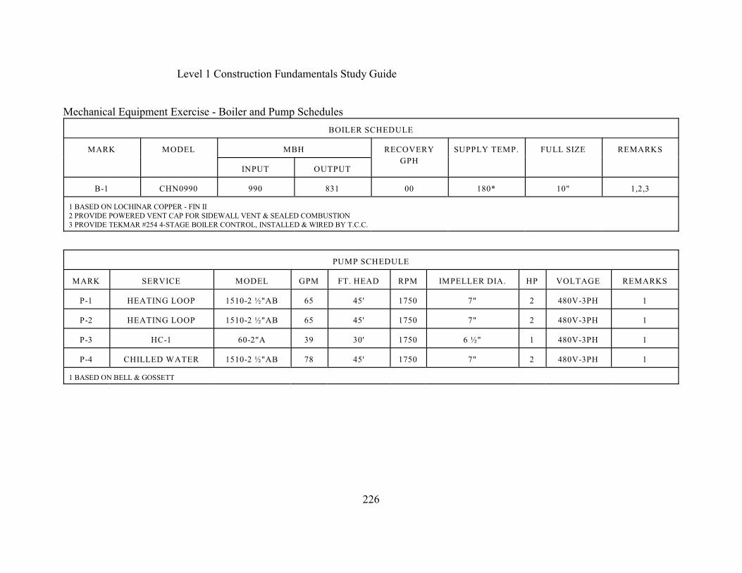
Level 1 Construction Fundamentals Study Guide
226
Mechanical Equipment Exercise - Boiler and Pump Schedules
BOILER SCHEDULE
MARK MODEL MBH RECOVERY
GPH
SUPPLY TEMP. FULL SIZE REMARKS
INPUT OUTPUT
B-1 CHN0990 990 831 00 180* 10" 1,2,3
1 BASED ON LOCHINAR COPPER - FIN II2 PROVIDE POWERED VENT CAP FOR SIDEWALL VENT & SEALED COMBUSTION3 PROVIDE TEKMAR #254 4-STAGE BOILER CONTROL, INSTALLED & WIRED BY T.C.C.
PUMP SCHEDULE
MARK SERVICE MODEL GPM FT. HEAD RPM IMPELLER DIA. HP VOLTAGE REMARKS
P-1 HEATING LOOP 1510-2 ½"AB 65 45' 1750 7" 2 480V-3PH 1
P-2 HEATING LOOP 1510-2 ½"AB 65 45' 1750 7" 2 480V-3PH 1
P-3 HC-1 60-2"A 39 30' 1750 6 ½" 1 480V-3PH 1
P-4 CHILLED WATER 1510-2 ½"AB 78 45' 1750 7" 2 480V-3PH 1
1 BASED ON BELL & GOSSETT

Level 1 Construction Fundamentals Study Guide
227
Mechanical Equipment Exercise - Gas Fired Package Rooftop Unit Schedules
GAS FIRED PACKAGE ROOFTOP UNIT SCHEDULE
MK LOCATION MODEL CFM EXT
S.P.
SAF
HP
SAF
RPM
VOLTAGE HTG. MBH
IN/OUT
COOLING
TOT/SEN
COMPRESSORS
NotesKW RLA LRA
RTU-1 SANC. 202 558DE240 7500 1" 7 ½ 1210 480v-3PH 270/216 235/173 20.6 31.4 223 1,2,3
RTU-2 SANC. 202 558DE240 7500 1" 7 ½ 1210 480v-3PH 270/216 235/173 20.6 31.4 223 1,2,3
RTU-3 Narthex 201 558DE090 3000 3/4" 3 1470 480V-3PH 180/144 73/84 7.69 6.2 37.7 1,3
1 BASED ON BRYANT2 PROVIDE W/INSULATED 24" HIGH ROOF CURB FOR SIDEWALL SUPPLY & RETURN3 PROVIDE 2/100% ECONOMIZER
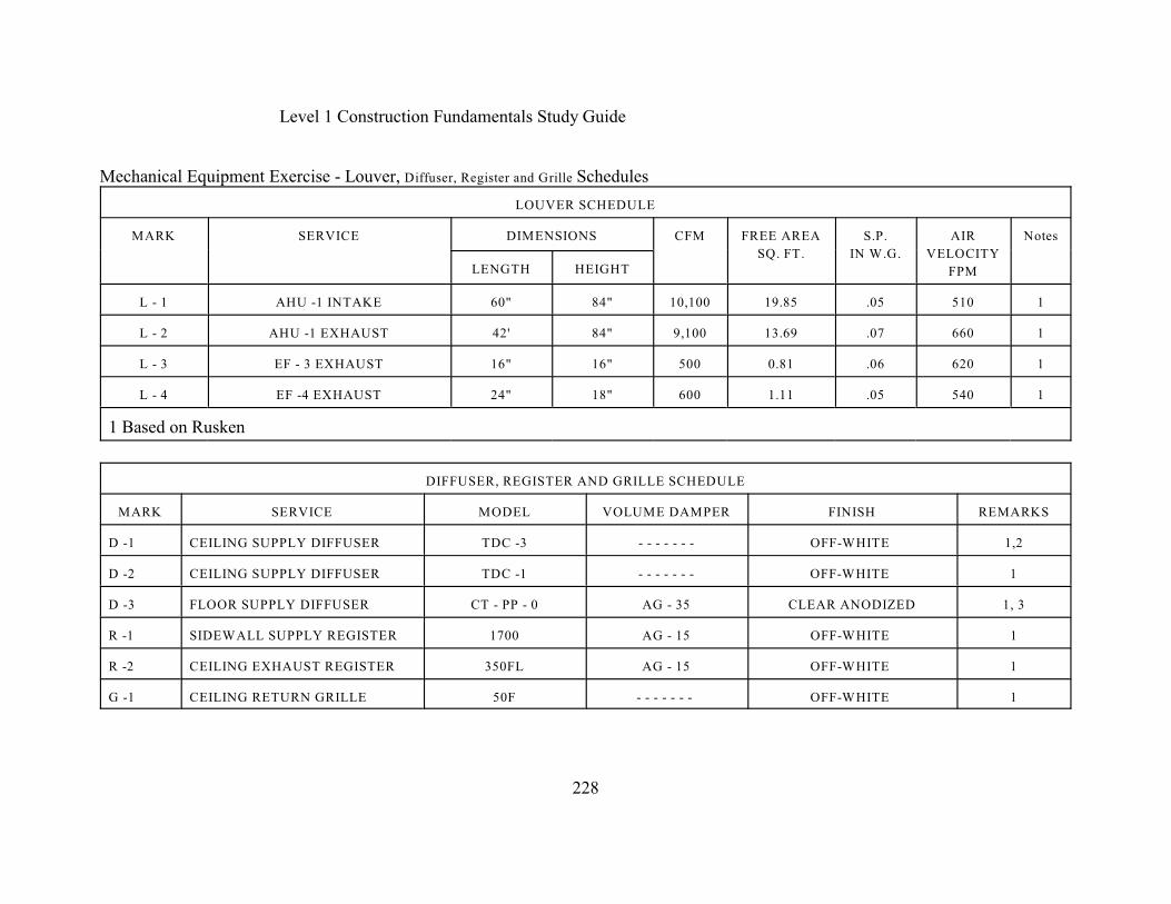
Level 1 Construction Fundamentals Study Guide
228
Mechanical Equipment Exercise - Louver, Diffuser, Register and Grille Schedules
LOUVER SCHEDULE
MARK SERVICE DIMENSIONS CFM FREE AREA
SQ. FT.
S.P.
IN W.G.
AIR
VELOCITY
FPM
Notes
LENGTH HEIGHT
L - 1 AHU -1 INTAKE 60" 84" 10,100 19.85 .05 510 1
L - 2 AHU -1 EXHAUST 42' 84" 9,100 13.69 .07 660 1
L - 3 EF - 3 EXHAUST 16" 16" 500 0.81 .06 620 1
L - 4 EF -4 EXHAUST 24" 18" 600 1.11 .05 540 1
1 Based on Rusken
DIFFUSER, REGISTER AND GRILLE SCHEDULE
MARK SERVICE MODEL VOLUME DAMPER FINISH REMARKS
D -1 CEILING SUPPLY DIFFUSER TDC -3 - - - - - - - OFF-WHITE 1,2
D -2 CEILING SUPPLY DIFFUSER TDC -1 - - - - - - - OFF-WHITE 1
D -3 FLOOR SUPPLY DIFFUSER CT - PP - 0 AG - 35 CLEAR ANODIZED 1, 3
R -1 SIDEWALL SUPPLY REGISTER 1700 AG - 15 OFF-WHITE 1
R -2 CEILING EXHAUST REGISTER 350FL AG - 15 OFF-WHITE 1
G -1 CEILING RETURN GRILLE 50F - - - - - - - OFF-WHITE 1
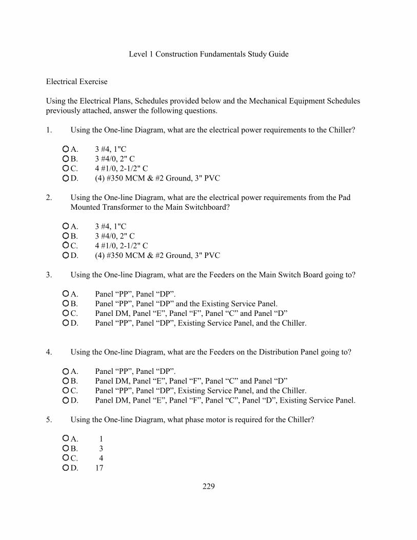
Level 1 Construction Fundamentals Study Guide
229
Electrical Exercise
Using the Electrical Plans, Schedules provided below and the Mechanical Equipment Schedulespreviously attached, answer the following questions.
1. Using the One-line Diagram, what are the electrical power requirements to the Chiller?
A. 3 #4, 1"CB. 3 #4/0, 2" CC. 4 #1/0, 2-1/2" CD. (4) #350 MCM & #2 Ground, 3" PVC
2. Using the One-line Diagram, what are the electrical power requirements from the PadMounted Transformer to the Main Switchboard?
A. 3 #4, 1"CB. 3 #4/0, 2" CC. 4 #1/0, 2-1/2" CD. (4) #350 MCM & #2 Ground, 3" PVC
3. Using the One-line Diagram, what are the Feeders on the Main Switch Board going to?
A. Panel “PP”, Panel “DP”.B. Panel “PP”, Panel “DP” and the Existing Service Panel.C. Panel DM, Panel “E”, Panel “F”, Panel “C” and Panel “D”D. Panel “PP”, Panel “DP”, Existing Service Panel, and the Chiller.
4. Using the One-line Diagram, what are the Feeders on the Distribution Panel going to?
A. Panel “PP”, Panel “DP”.B. Panel DM, Panel “E”, Panel “F”, Panel “C” and Panel “D”C. Panel “PP”, Panel “DP”, Existing Service Panel, and the Chiller.D. Panel DM, Panel “E”, Panel “F”, Panel “C”, Panel “D”, Existing Service Panel.
5. Using the One-line Diagram, what phase motor is required for the Chiller?
A. 1B. 3C. 4D. 17
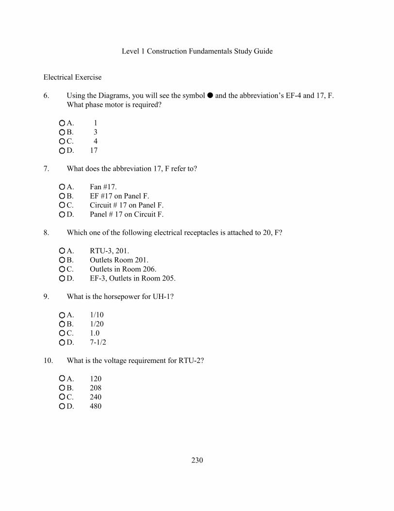
Level 1 Construction Fundamentals Study Guide
230
Electrical Exercise
6. Using the Diagrams, you will see the symbol � and the abbreviation’s EF-4 and 17, F.What phase motor is required?
A. 1B. 3C. 4D. 17
7. What does the abbreviation 17, F refer to?
A. Fan #17.B. EF #17 on Panel F.C. Circuit # 17 on Panel F.D. Panel # 17 on Circuit F.
8. Which one of the following electrical receptacles is attached to 20, F?
A. RTU-3, 201.B. Outlets Room 201.C. Outlets in Room 206.D. EF-3, Outlets in Room 205.
9. What is the horsepower for UH-1?
A. 1/10B. 1/20C. 1.0D. 7-1/2
10. What is the voltage requirement for RTU-2?
A. 120 B. 208C. 240D. 480
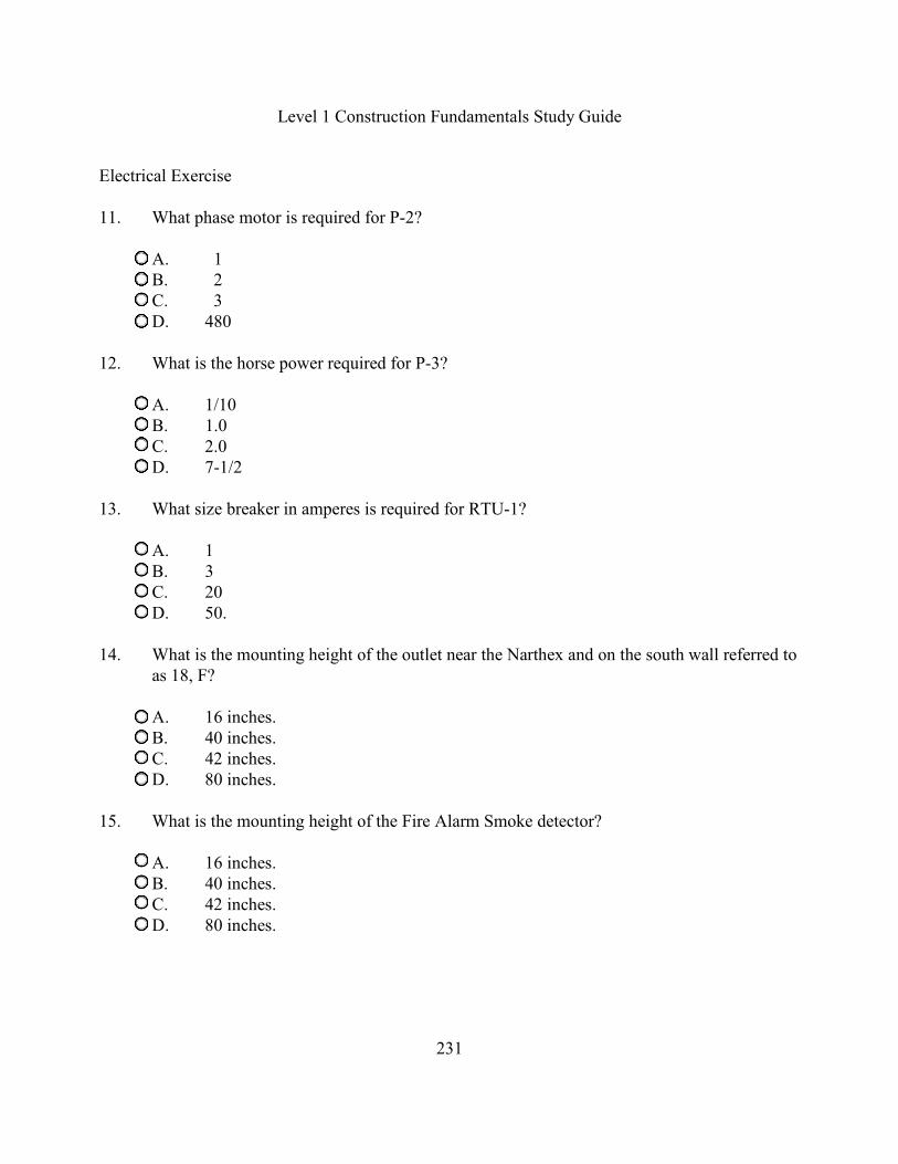
Level 1 Construction Fundamentals Study Guide
231
Electrical Exercise
11. What phase motor is required for P-2?
A. 1B. 2C. 3D. 480
12. What is the horse power required for P-3?
A. 1/10B. 1.0C. 2.0D. 7-1/2
13. What size breaker in amperes is required for RTU-1?
A. 1B. 3C. 20D. 50.
14. What is the mounting height of the outlet near the Narthex and on the south wall referred toas 18, F?
A. 16 inches.B. 40 inches.C. 42 inches.D. 80 inches.
15. What is the mounting height of the Fire Alarm Smoke detector?
A. 16 inches.B. 40 inches.C. 42 inches.D. 80 inches.
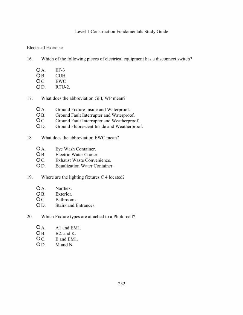
Level 1 Construction Fundamentals Study Guide
232
Electrical Exercise
16. Which of the following pieces of electrical equipment has a disconnect switch?
A. EF-3B. CUHC EWCD. RTU-2.
17. What does the abbreviation GFI, WP mean?
A. Ground Fixture Inside and Waterproof.B. Ground Fault Interrupter and Waterproof.C. Ground Fault Interrupter and Weatherproof.D. Ground Fluorescent Inside and Weatherproof.
18. What does the abbreviation EWC mean?
A. Eye Wash Container.B. Electric Water Cooler.C. Exhaust Waste Convenience.D. Equalization Water Container.
19. Where are the lighting fixtures C 4 located?
A. Narthex.B. Exterior.C. Bathrooms.D. Stairs and Entrances.
20. Which Fixture types are attached to a Photo-cell?
A. A1 and EM1.B. B2. and K.C. E and EM1.D. M and N.

Level 1 Construction Fundamentals Study Guide
233
Electrical Exercise
21. What type of light is a B2 light?
A. 2' x 2' Fluorescent Troffer with Prismatic lens.B. 2' x 4' Fluorescent Troffer with Prismatic lens.C. 2' x 4' Fluorescent Troffer with Prismatic lens with 3 lamps.D. 2' x 2' Fluorescent Troffer with Parabolic lens and 30K lamps.
22. How are the EM-2 lights mounted?
A. Ceiling.B. Surface.C. Pendant.D. Recessed.
23. How many lamp(s) are in fixture A2?
A. 1B. 2C. 3D. 4
24. What is the electrical symbol ¤ with an E inside the circle mean?
A. Exit Sign.B. Existing Sign.C. Electrical Fixture.D. Emergency Fixture.
25. Which of the following wire sizes has the greatest diameter?
A. #0B. #1C. #10D. #14.
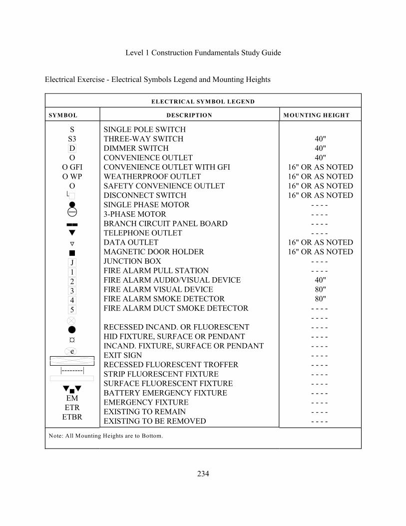
Level 1 Construction Fundamentals Study Guide
234
Electrical Exercise - Electrical Symbols Legend and Mounting Heights
ELECTRICAL SYMBOL LEGEND
SYMBOL DESCRIPTION MOUNTING HEIGHT
SS3DO
O GFIO WP
O. �×,,�
«�J12345
¤e
|--------|
�(�EMETR
ETBR
SINGLE POLE SWITCHTHREE-WAY SWITCHDIMMER SWITCHCONVENIENCE OUTLETCONVENIENCE OUTLET WITH GFIWEATHERPROOF OUTLETSAFETY CONVENIENCE OUTLETDISCONNECT SWITCHSINGLE PHASE MOTOR3-PHASE MOTORBRANCH CIRCUIT PANEL BOARDTELEPHONE OUTLETDATA OUTLETMAGNETIC DOOR HOLDERJUNCTION BOXFIRE ALARM PULL STATIONFIRE ALARM AUDIO/VISUAL DEVICEFIRE ALARM VISUAL DEVICEFIRE ALARM SMOKE DETECTORFIRE ALARM DUCT SMOKE DETECTOR
RECESSED INCAND. OR FLUORESCENTHID FIXTURE, SURFACE OR PENDANTINCAND. FIXTURE, SURFACE OR PENDANTEXIT SIGNRECESSED FLUORESCENT TROFFERSTRIP FLUORESCENT FIXTURESURFACE FLUORESCENT FIXTUREBATTERY EMERGENCY FIXTUREEMERGENCY FIXTUREEXISTING TO REMAINEXISTING TO BE REMOVED
40"40"40"
16" OR AS NOTED16" OR AS NOTED16" OR AS NOTED16" OR AS NOTED
- - - - - - - - - - - - - - - -
16" OR AS NOTED16" OR AS NOTED
- - - - - - - - 40"80"80"
- - - - - - - - - - - - - - - - - - - - - - - - - - - - - - - - - - - - - - - - - - - - - - - - - - - -
Note: All Mounting Heights are to Bottom.

Level 1 Construction Fundamentals Study Guide
235
Electrical Exercise - One Line Diagram

Level 1 Construction Fundamentals Study Guide
236
Electrical Exercise - Power Plan Upper Level
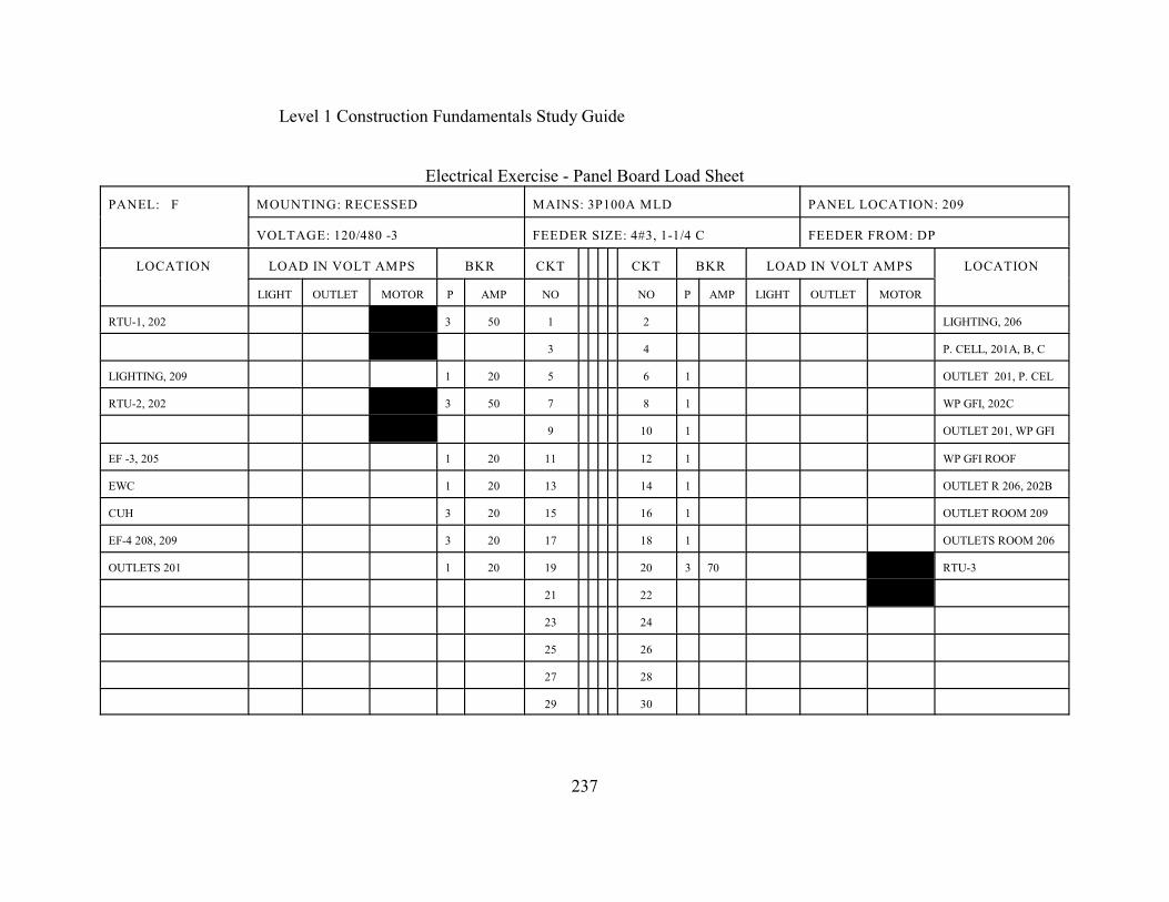
Level 1 Construction Fundamentals Study Guide
237
Electrical Exercise - Panel Board Load Sheet
PANEL: F MOUNTING: RECESSED MAINS: 3P100A MLD PANEL LOCATION: 209
VOLTAGE: 120/480 -3 FEEDER SIZE: 4#3, 1-1/4 C FEEDER FROM: DP
LOCATION LOAD IN VOLT AMPS BKR CKT CKT BKR LOAD IN VOLT AMPS LOCATION
LIGHT OUTLET MOTOR P AMP NO NO P AMP LIGHT OUTLET MOTOR
RTU-1, 202 480 3 50 1 2 LIGHTING, 206
3 4 P. CELL, 201A, B, C
LIGHTING, 209 1 20 5 6 1 OUTLET 201, P. CEL
RTU-2, 202 480 3 50 7 8 1 WP GFI, 202C
9 10 1 OUTLET 201, WP GFI
EF -3, 205 1 20 11 12 1 WP GFI ROOF
EWC 1 20 13 14 1 OUTLET R 206, 202B
CUH 3 20 15 16 1 OUTLET ROOM 209
EF-4 208, 209 3 20 17 18 1 OUTLETS ROOM 206
OUTLETS 201 1 20 19 20 3 70 480 RTU-3
21 22
23 24
25 26
27 28
29 30
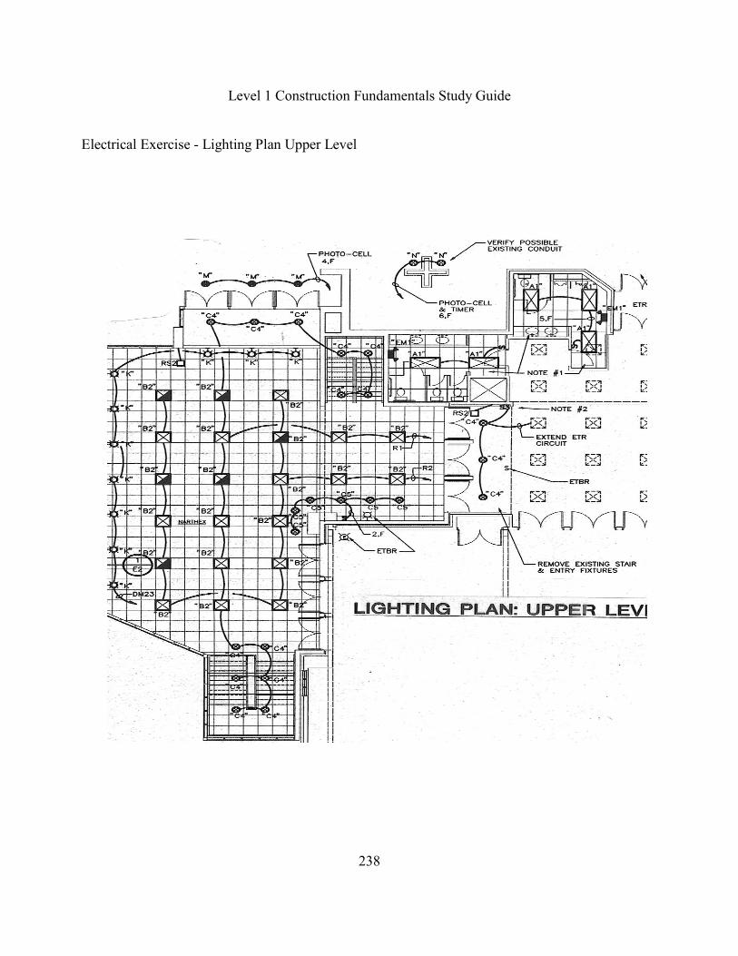
Level 1 Construction Fundamentals Study Guide
238
Electrical Exercise - Lighting Plan Upper Level

Level 1 Construction Fundamentals Study Guide
239
Electrical Exercise - Lighting Fixture Legend
DESCRIPTION MOUNTING LAMPS MANUFACTURER
A1 2' X 4' FLUORESCENT TOFFER
W/ PRISMATIC LENS
RECESSED (2) F40CW/RS/WM LITHONIA #2SPG-
240
A2 2' x 4' SIMILAR TO A1
EXCEPT W/ 3 LAMPS
RECESSED (3) F40CW/RS/WM LITHONIA #2SPG-
340
B1 2' X 2' FLUORESCENT
TROFFER W/PRISMATIC LEN
RECESSED (2) FB40CW/6 LITHONIA #2SPG-
2U40
4
B2 SIMILAR TO B1 EXCEPT W/
PARABOLIC LENS & 30K
LAMPS
RECESSED (2) F40SPX30/U/6 LITHONIA #2PM3 6, 4
C1 INCANDESCENT DOWNLIGHT RECESSED (1)15ORFL120WM KURT VERSEN #150
C2 SIMILAR TO C1 EXCEPT W/
LAMP
RECESSED (1)300RFL KURT VERSEN #300
C3 SIMILAR TO C1 EXCEPTW/
LAMP
RECESSED (1)Q500 T4 KURT VERSEN #500
C4 SIMILAR TO C1 EXCEPT W/
FLUORESCENT LAMP
RECESSED (2)PLC26W/27 KURT VERSEN #120 12
C5 SIMILAR TO C1 EXCEPT
WALLWASH
RECESSED (2)PLC26W/27 KURT VERSEN #120
D PENDANT INCANDESCENT
FIXTURE, ACRYLIC DIFFUSER
PENDANT (8)N150 VISA #CB3616 13
K INCANDESCENT UP/DOWN
LIGHT
WALL PER
DETAIL
(1)100A21/99 MANNING #DS89 10
M HID DOWNLIGHT RECESSED (1)MS100BU/BDW HALO #M6024
N HID WELL UPLIGHT WELL IN
GROUND
(1)MS100BU/BDW HYDREL #9305
EM
1
EMERGENCY BATTERY
FIXTURE
SURFACE PER UNIT LITHONIA #ELM-H
EM
2
SAME AS EM1 EXCEPT
CEILING MOUNTED
CEILING PER UNIT LITHONIA #ELM-H

Level 1 Construction Fundamentals Study Guide
240
Electrical Exercise - Lighting Fixture Notes
1. ALL BALLAST SHALL BE ENERGY SAVING TYPE, FLUORESCENT (T12) BALLAST.
2. HID LAMPS BY VENTURE, ‘PL’ LAMPS BY OSRAM AND ALL OTHER LAMPS BY G.E. WITH
EQUAL BY SYLVANIA.
3. EXIT SIGNS ARE BATTERY POWERED LED TYPE.
4. PARTIALLY SHADED FIXTURES SHALL INCLUDE 1/3 OR ½ OF LAMPS ON BATTERY BACKUP
EMERGENCY PACK SUCH FIXTURES ARE NORMALLY MANUALLY CONTROLLED AND
AUTOMATICALLY LIGHT DURING LOSS OF POWER.
5. EQUAL FIXTURES BY LITHONIA, DAYBRITE, METALUX, HALO, AND CAPRI, ARE APPROVED.
FIXTURE CUTS MUST BE SUBMITTED FOR SPECIFIC FIXTURES NOT LISTED ABOVE.
6. NOT THE USE OF 30K LAMPS FOR THE PARABOLIC 2 X 2 FIXTURES.
7. FIXTURES TYPE ‘E1' & ‘E2' SHALL MATCH ‘D’, INCLUDING THE BRASS RING AROUND THE
UPPER PART OF THE FIXTURE. FIXTURE ‘E2' IS ONLY 1/4 OF A SPHERE FOR CORNER
MOUNTING, ACRYLIC OR MATCHING PAINT FINISH. FIXTURE TO SET OUT FROM WALL.
8. OF THE 18 TYPE ‘F’ FIXTURES, PROVIDING AT LEAST THREE (3) FIXTURES OF EACH BEAM
TYPE CL, VNSP, NSP, MFL, & WFL. INCLUDE THREE (3) SETS OF SPARE LENS #S4PAR-LS.
EQUAL FIXTURES BY STRAND SHALL BE APPROVED EQUALS. SEE ELEC. & ARCH DETAILS
FOR INSTALLATION.
9. FIXTURE ‘G’ TO HAVE CLEAR LENS TO PREVENT COLLECTION OF DUST IN REFLECTOR.
PROVIDE PHOTOMETRICS OF SIDE, FRONT & REAR WITH FIXTURE INVERTED PER DETAIL #7
ON DWG. E2.
10. UP/DOWN FIXTURE ‘K’ TO MOUNT DIRECTLY TO WALL PER DETAIL #1 ON DWG. E2.
11. FLOOD LIGHTING FIXTURE ‘P’ COLOR TO MATCH ROOF FINISH.
12. FIXTURE MUST BE ‘IC’ RATED.
13. ‘D’ FIXTURE BY VISA WITH WHITE PENDANT, LBZ RING & NO FINAL. ‘D’ FIXTURE BY
MANNING WITH WHITE PENDANT ‘DB’ RING & NO FINAL.