Configuration Guide: TPCS-4SM & TPCS-4SMD
20
Crestron TPCS-4SM & TPCS-4SMD 4.3” Touch Screen Control Systems Configuration Guide
Transcript of Configuration Guide: TPCS-4SM & TPCS-4SMD

Crestron TPCS-4SM & TPCS-4SMD 4.3” Touch Screen Control Systems Configuration Guide

This document was prepared and written by the Technical Documentation department at:
The specific patents that cover Crestron products are listed at www.crestronpatents.com.
Crestron, the Crestron logo and Crestron Toolbox are either trademarks or registered trademarks of Crestron Electronics, Inc. in the United States and/or other countries. Internet Explorer is either a trademark or registered trademark of Microsoft Corporation in the
United States and/or other countries. Other trademarks and trade names may be used in this document to refer to either the entities claiming the marks and names or their products. Crestron disclaims any proprietary interest in the marks and names of others.
©2012 Crestron Electronics, Inc.
Crestron TPCS-4SM & TPCS-4SMD Touch Screen Control Systems
Contents
4.3” Touch Screen Control Systems: TPCS-4SM & TPCS-4SMD 1 Access the Setup Screens...........................................................................................................1 Configure the TPCS-4SM or TPCS-4SMD...............................................................................3
Ethernet Setup .............................................................................................................3 Audio Setup.................................................................................................................8 Display Setup ..............................................................................................................8 Application Setup ......................................................................................................10 Standby Timeout .......................................................................................................11 Diagnostics ................................................................................................................12 About.........................................................................................................................15 Save & Exit ...............................................................................................................15
Configuration Guide – DOC. 7332A Contents • i

Crestron TPCS-4SM & TPCS-4SMD Touch Screen Control Systems
4.3” Touch Screen Control Systems: TPCS-4SM & TPCS-4SMD
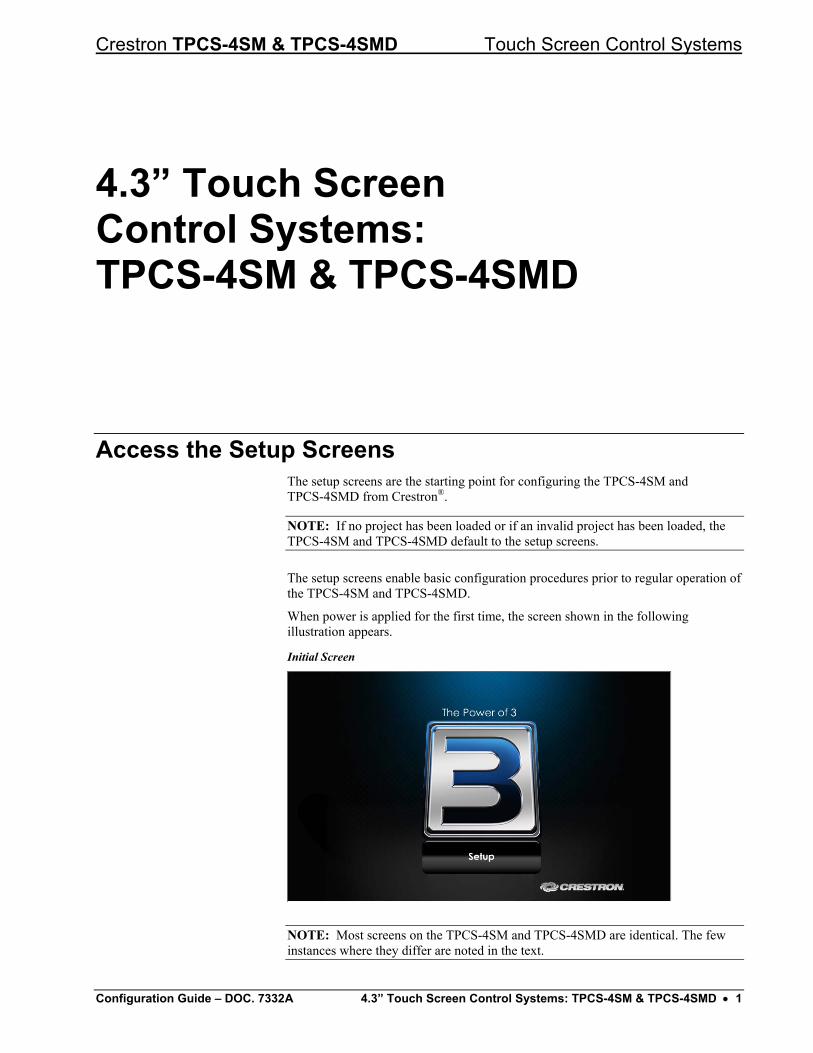
Access the Setup Screens The setup screens are the starting point for configuring the TPCS-4SM and TPCS-4SMD from Crestron®.
NOTE: If no project has been loaded or if an invalid project has been loaded, the TPCS-4SM and TPCS-4SMD default to the setup screens.
The setup screens enable basic configuration procedures prior to regular operation of the TPCS-4SM and TPCS-4SMD.
When power is applied for the first time, the screen shown in the following illustration appears.
Initial Screen
NOTE: Most screens on the TPCS-4SM and TPCS-4SMD are identical. The few instances where they differ are noted in the text.
Configuration Guide – DOC. 7332A 4.3” Touch Screen Control Systems: TPCS-4SM & TPCS-4SMD • 1
Touch Screen Control Systems Crestron TPCS-4SM & TPCS-4SMD
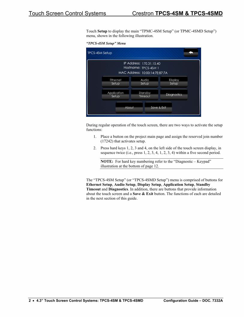
Touch Setup to display the main “TPMC-4SM Setup” (or TPMC-4SMD Setup”) menu, shown in the following illustration.
“TPCS-4SM Setup” Menu
During regular operation of the touch screen, there are two ways to activate the setup functions:
1. Place a button on the project main page and assign the reserved join number (17242) that activates setup.
2. Press hard keys 1, 2, 3 and 4, on the left side of the touch screen display, in sequence twice (i.e., press 1, 2, 3, 4, 1, 2, 3, 4) within a five second period.
NOTE: For hard key numbering refer to the “Diagnostic – Keypad” illustration at the bottom of page 12.
The “TPCS-4SM Setup” (or “TPCS-4SMD Setup”) menu is comprised of buttons for Ethernet Setup, Audio Setup, Display Setup, Application Setup, Standby Timeout and Diagnostics. In addition, there are buttons that provide information about the touch screen and a Save & Exit button. The functions of each are detailed in the next section of this guide.
2 • 4.3” Touch Screen Control Systems: TPCS-4SM & TPCS-4SMD Configuration Guide – DOC. 7332A
Crestron TPCS-4SM & TPCS-4SMD Touch Screen Control Systems
Configure the TPCS-4SM or TPCS-4SMD
Ethernet Setup On the “TPCS-4SM[D] Setup” menu, touch Ethernet Setup to display the “Ethernet Setup” menu, shown in the following illustration.
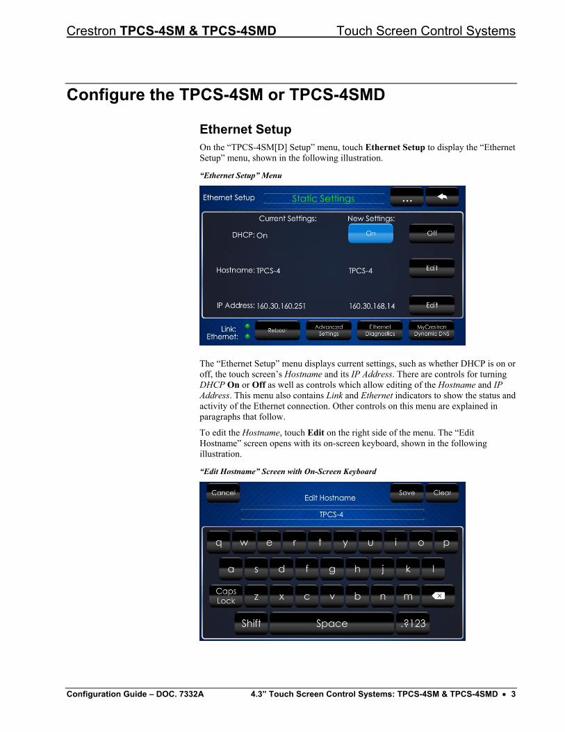
“Ethernet Setup” Menu
The “Ethernet Setup” menu displays current settings, such as whether DHCP is on or off, the touch screen’s Hostname and its IP Address. There are controls for turning DHCP On or Off as well as controls which allow editing of the Hostname and IP Address. This menu also contains Link and Ethernet indicators to show the status and activity of the Ethernet connection. Other controls on this menu are explained in paragraphs that follow.
To edit the Hostname, touch Edit on the right side of the menu. The “Edit Hostname” screen opens with its on-screen keyboard, shown in the following illustration.
“Edit Hostname” Screen with On-Screen Keyboard
Configuration Guide – DOC. 7332A 4.3” Touch Screen Control Systems: TPCS-4SM & TPCS-4SMD • 3
Touch Screen Control Systems Crestron TPCS-4SM & TPCS-4SMD
Use the keyboard to enter the new name. Touch Clear to clear any previous entry, Save to save a new entry or Cancel to return to the previous screen.
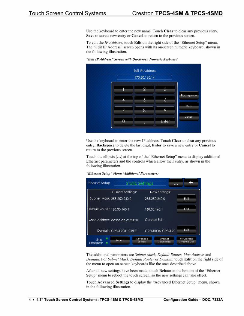
To edit the IP Address, touch Edit on the right side of the “Ethernet Setup” menu. The “Edit IP Address” screen opens with its on-screen numeric keyboard, shown in the following illustration.
“Edit IP Address” Screen with On-Screen Numeric Keyboard
Use the keyboard to enter the new IP address. Touch Clear to clear any previous entry, Backspace to delete the last digit, Enter to save a new entry or Cancel to return to the previous screen.
Touch the ellipsis (…) at the top of the “Ethernet Setup” menu to display additional Ethernet parameters and the controls which allow their entry, as shown in the following illustration.
“Ethernet Setup” Menu (Additional Parameters)
The additional parameters are Subnet Mask, Default Router, Mac Address and Domain. For Subnet Mask, Default Router or Domain, touch Edit on the right side of the menu to open on-screen keyboards like the ones described above.
After all new settings have been made, touch Reboot at the bottom of the “Ethernet Setup” menu to reboot the touch screen, so the new settings can take effect.
Touch Advanced Settings to display the “Advanced Ethernet Setup” menu, shown in the following illustration.
4 • 4.3” Touch Screen Control Systems: TPCS-4SM & TPCS-4SMD Configuration Guide – DOC. 7332A
Crestron TPCS-4SM & TPCS-4SMD Touch Screen Control Systems
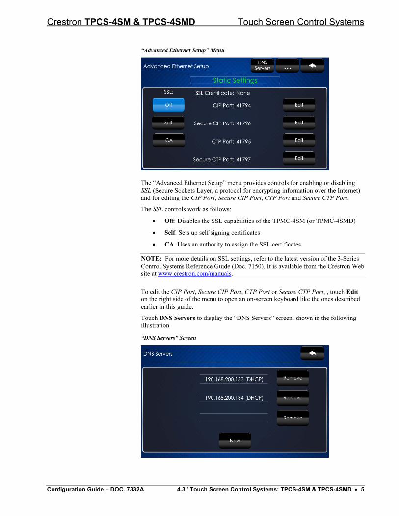
“Advanced Ethernet Setup” Menu
The “Advanced Ethernet Setup” menu provides controls for enabling or disabling SSL (Secure Sockets Layer, a protocol for encrypting information over the Internet) and for editing the CIP Port, Secure CIP Port, CTP Port and Secure CTP Port.
The SSL controls work as follows:
• Off: Disables the SSL capabilities of the TPMC-4SM (or TPMC-4SMD)
• Self: Sets up self signing certificates
• CA: Uses an authority to assign the SSL certificates
NOTE: For more details on SSL settings, refer to the latest version of the 3-Series Control Systems Reference Guide (Doc. 7150). It is available from the Crestron Web site at www.crestron.com/manuals.
To edit the CIP Port, Secure CIP Port, CTP Port or Secure CTP Port, , touch Edit on the right side of the menu to open an on-screen keyboard like the ones described earlier in this guide.
Touch DNS Servers to display the “DNS Servers” screen, shown in the following illustration.
“DNS Servers” Screen
Configuration Guide – DOC. 7332A 4.3” Touch Screen Control Systems: TPCS-4SM & TPCS-4SMD • 5
Touch Screen Control Systems Crestron TPCS-4SM & TPCS-4SMD
The “DNS Servers” screen provides controls for adding or deleting the IP addresses of DNS (Domain Name System) registered computers on the network. To add a server’s IP address, touch New to open an on-screen keyboard.
Use the keyboard to enter the IP address of the new DNS server. Touch Clear to clear any previous entry, Backspace to delete the last digit, Enter to save a new entry or Cancel to return to the previous screen.
On the “Advanced Ethernet Setup” menu, touch the ellipsis (…) at the top to display the On and Off controls which allow enabling or disabling the Webserver and for editing the Web Port and Secure Web Port.
The default Webserver setting is On. Touching Off disables access to setup from a Web browser.
To edit the Web Port or Secure Web Port, touch Edit on the right side of the screen to open an on-screen keyboard like the ones described earlier in this guide.
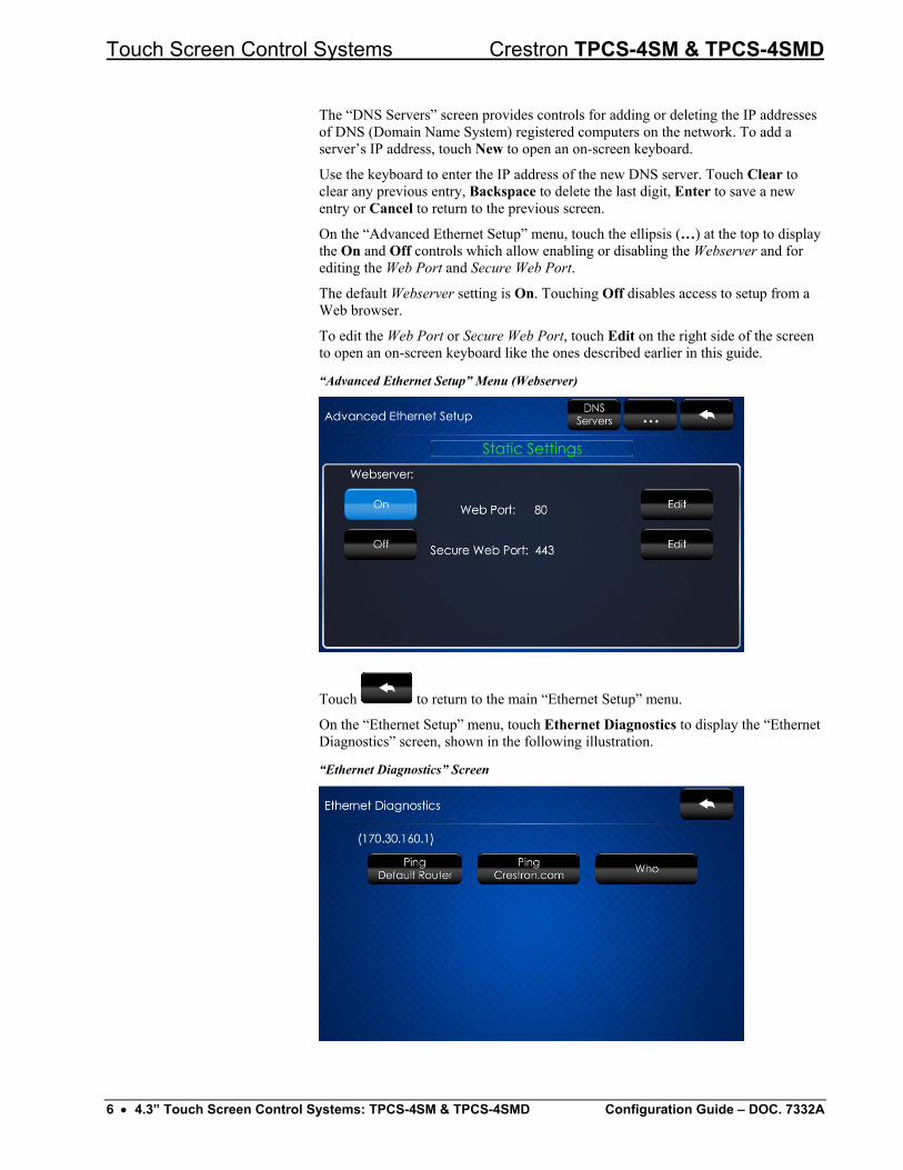
“Advanced Ethernet Setup” Menu (Webserver)
Touch to return to the main “Ethernet Setup” menu.
On the “Ethernet Setup” menu, touch Ethernet Diagnostics to display the “Ethernet Diagnostics” screen, shown in the following illustration.
“Ethernet Diagnostics” Screen
6 • 4.3” Touch Screen Control Systems: TPCS-4SM & TPCS-4SMD Configuration Guide – DOC. 7332A
Crestron TPCS-4SM & TPCS-4SMD Touch Screen Control Systems
The “Ethernet Diagnostics” screen provides controls for verifying connections. Touch Ping Default Router to verify connection to the router. (The screen displays a “Passed” message to show successful connection.) Touch Ping Crestron.com to verify connection to an external DNS server.
Touch Who to display a list of devices connected to the PC via the Ethernet connection. These devices may be Crestron Ethernet devices, third-party Ethernet devices or PCs (including any PC using Crestron Toolbox™ to connect to the processor via Ethernet).
Touch to return to the “Ethernet Setup” menu.
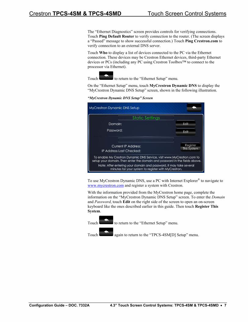
On the “Ethernet Setup” menu, touch MyCrestron Dynamic DNS to display the “MyCrestron Dynamic DNS Setup” screen, shown in the following illustration.
“MyCrestron Dynamic DNS Setup” Screen
To use MyCrestron Dynamic DNS, use a PC with Internet Explorer® to navigate to www.mycrestron.com and register a system with Crestron.
With the information provided from the MyCrestron home page, complete the information on the “MyCrestron Dynamic DNS Setup” screen. To enter the Domain and Password, touch Edit on the right side of the screen to open an on-screen keyboard like the ones described earlier in this guide. Then touch Register This System.
Touch to return to the “Ethernet Setup” menu.
Touch again to return to the “TPCS-4SM[D] Setup” menu.
Configuration Guide – DOC. 7332A 4.3” Touch Screen Control Systems: TPCS-4SM & TPCS-4SMD • 7
Touch Screen Control Systems Crestron TPCS-4SM & TPCS-4SMD
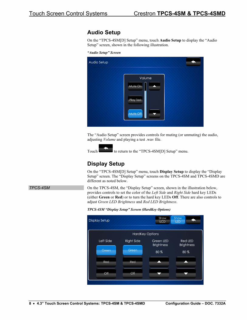
Audio Setup On the “TPCS-4SM[D] Setup” menu, touch Audio Setup to display the “Audio Setup” screen, shown in the following illustration.
“Audio Setup” Screen
The “Audio Setup” screen provides controls for muting (or unmuting) the audio, adjusting Volume and playing a test .wav file.
Touch to return to the “TPCS-4SM[D] Setup” menu.
Display Setup On the “TPCS-4SM[D] Setup” menu, touch Display Setup to display the “Display Setup” screen. The “Display Setup” screens on the TPCS-4SM and TPCS-4SMD are different as noted below.
TPCS-4SM On the TPCS-4SM, the “Display Setup” screen, shown in the illustration below, provides controls to set the color of the Left Side and Right Side hard key LEDs (either Green or Red) or to turn the hard key LEDs Off. There are also controls to adjust Green LED Brightness and Red LED Brightness.
TPCS-4SM “Display Setup” Screen (HardKey Options)
8 • 4.3” Touch Screen Control Systems: TPCS-4SM & TPCS-4SMD Configuration Guide – DOC. 7332A
Crestron TPCS-4SM & TPCS-4SMD Touch Screen Control Systems
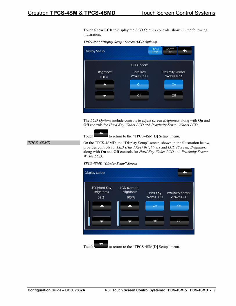
Touch Show LCD to display the LCD Options controls, shown in the following illustration.
TPCS-4SM “Display Setup” Screen (LCD Options)
The LCD Options include controls to adjust screen Brightness along with On and Off controls for Hard Key Wakes LCD and Proximity Sensor Wakes LCD.
Touch to return to the “TPCS-4SM[D] Setup” menu.
TPCS-4SMD On the TPCS-4SMD, the “Display Setup” screen, shown in the illustration below, provides controls for LED (Hard Key) Brightness and LCD (Screen) Brightness along with On and Off controls for Hard Key Wakes LCD and Proximity Sensor Wakes LCD.
TPCS-4SMD “Display Setup” Screen
Touch to return to the “TPCS-4SM[D] Setup” menu.
Configuration Guide – DOC. 7332A 4.3” Touch Screen Control Systems: TPCS-4SM & TPCS-4SMD • 9
Touch Screen Control Systems Crestron TPCS-4SM & TPCS-4SMD
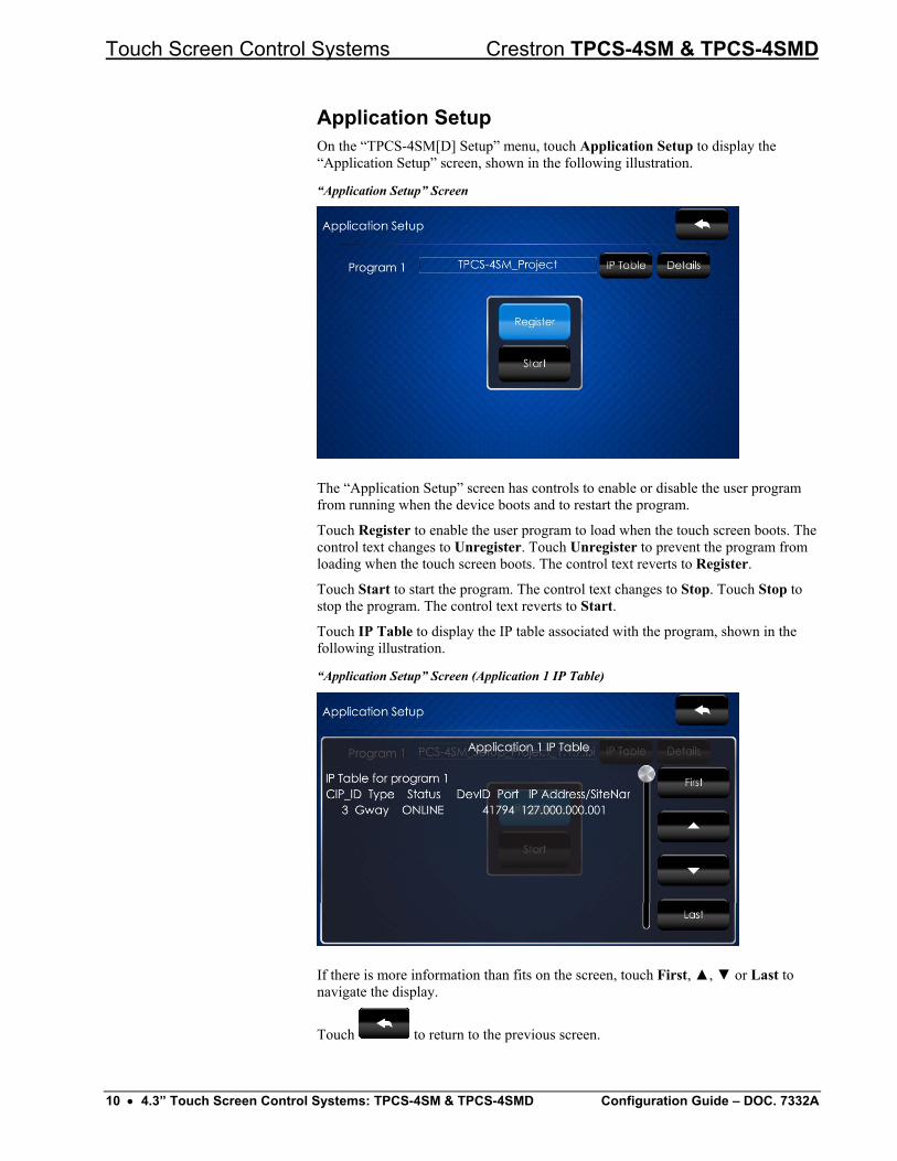
Application Setup On the “TPCS-4SM[D] Setup” menu, touch Application Setup to display the “Application Setup” screen, shown in the following illustration.
“Application Setup” Screen
The “Application Setup” screen has controls to enable or disable the user program from running when the device boots and to restart the program.
Touch Register to enable the user program to load when the touch screen boots. The control text changes to Unregister. Touch Unregister to prevent the program from loading when the touch screen boots. The control text reverts to Register.
Touch Start to start the program. The control text changes to Stop. Touch Stop to stop the program. The control text reverts to Start.
Touch IP Table to display the IP table associated with the program, shown in the following illustration.
“Application Setup” Screen (Application 1 IP Table)
If there is more information than fits on the screen, touch First, ▲, ▼ or Last to navigate the display.
Touch to return to the previous screen.
10 • 4.3” Touch Screen Control Systems: TPCS-4SM & TPCS-4SMD Configuration Guide – DOC. 7332A
Crestron TPCS-4SM & TPCS-4SMD Touch Screen Control Systems
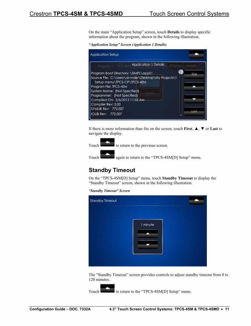
On the main “Application Setup” screen, touch Details to display specific information about the program, shown in the following illustration.
“Application Setup” Screen (Application 1 Details)
If there is more information than fits on the screen, touch First, ▲, ▼ or Last to navigate the display.
Touch to return to the previous screen.
Touch again to return to the “TPCS-4SM[D] Setup” menu.
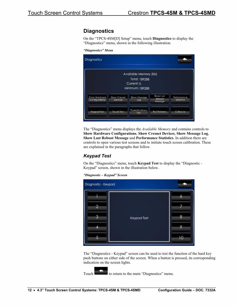
Standby Timeout On the “TPCS-4SM[D] Setup” menu, touch Standby Timeout to display the “Standby Timeout” screen, shown in the following illustration.
“Standby Timeout” Screen
The “Standby Timeout” screen provides controls to adjust standby timeout from 0 to 120 minutes.
Touch to return to the “TPCS-4SM[D] Setup” menu.
Configuration Guide – DOC. 7332A 4.3” Touch Screen Control Systems: TPCS-4SM & TPCS-4SMD • 11
Touch Screen Control Systems Crestron TPCS-4SM & TPCS-4SMD
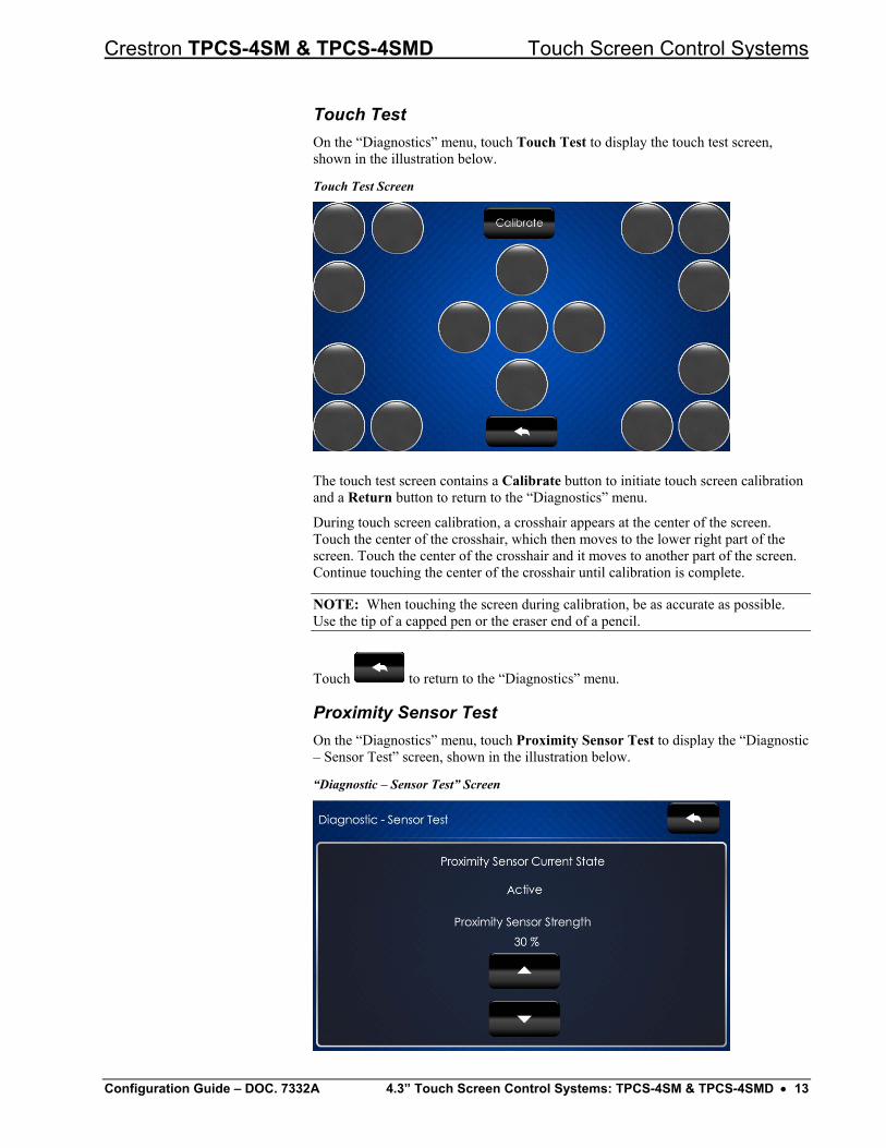
Diagnostics On the “TPCS-4SM[D] Setup” menu, touch Diagnostics to display the “Diagnostics” menu, shown in the following illustration.
“Diagnostics” Menu
The “Diagnostics” menu displays the Available Memory and contains controls to Show Hardware Configurations, Show Cresnet Devices, Show Message Log, Show Last Reboot Message and Performance Statistics. In addition there are controls to open various test screens and to initiate touch screen calibration. These are explained in the paragraphs that follow.
Keypad Test On the “Diagnostics” menu, touch Keypad Test to display the “Diagnostic - Keypad” screen, shown in the illustration below.
“Diagnostic – Keypad” Screen
The “Diagnostics - Keypad” screen can be used to test the function of the hard key push buttons on either side of the screen. When a button is pressed, its corresponding indication on the screen lights.
Touch to return to the main “Diagnostics” menu.
12 • 4.3” Touch Screen Control Systems: TPCS-4SM & TPCS-4SMD Configuration Guide – DOC. 7332A
Crestron TPCS-4SM & TPCS-4SMD Touch Screen Control Systems
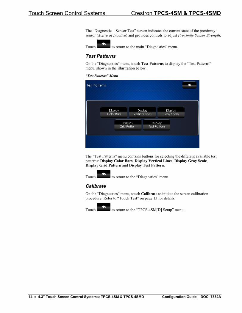
Touch Test On the “Diagnostics” menu, touch Touch Test to display the touch test screen, shown in the illustration below.
Touch Test Screen
The touch test screen contains a Calibrate button to initiate touch screen calibration and a Return button to return to the “Diagnostics” menu.
During touch screen calibration, a crosshair appears at the center of the screen. Touch the center of the crosshair, which then moves to the lower right part of the screen. Touch the center of the crosshair and it moves to another part of the screen. Continue touching the center of the crosshair until calibration is complete.
NOTE: When touching the screen during calibration, be as accurate as possible. Use the tip of a capped pen or the eraser end of a pencil.
Touch to return to the “Diagnostics” menu.
Proximity Sensor Test On the “Diagnostics” menu, touch Proximity Sensor Test to display the “Diagnostic – Sensor Test” screen, shown in the illustration below.
“Diagnostic – Sensor Test” Screen
Configuration Guide – DOC. 7332A 4.3” Touch Screen Control Systems: TPCS-4SM & TPCS-4SMD • 13
Touch Screen Control Systems Crestron TPCS-4SM & TPCS-4SMD
The “Diagnostic – Sensor Test” screen indicates the current state of the proximity sensor (Active or Inactive) and provides controls to adjust Proximity Sensor Strength.
Touch to return to the main “Diagnostics” menu.
Test Patterns On the “Diagnostics” menu, touch Test Patterns to display the “Test Patterns” menu, shown in the illustration below.
“Test Patterns” Menu
The “Test Patterns” menu contains buttons for selecting the different available test patterns: Display Color Bars, Display Vertical Lines, Display Gray Scale, Display Grid Pattern and Display Test Pattern.
Touch to return to the “Diagnostics” menu.
Calibrate On the “Diagnostics” menu, touch Calibrate to initiate the screen calibration procedure. Refer to “Touch Test” on page 13 for details.
Touch to return to the “TPCS-4SM[D] Setup” menu.
14 • 4.3” Touch Screen Control Systems: TPCS-4SM & TPCS-4SMD Configuration Guide – DOC. 7332A
Crestron TPCS-4SM & TPCS-4SMD Touch Screen Control Systems
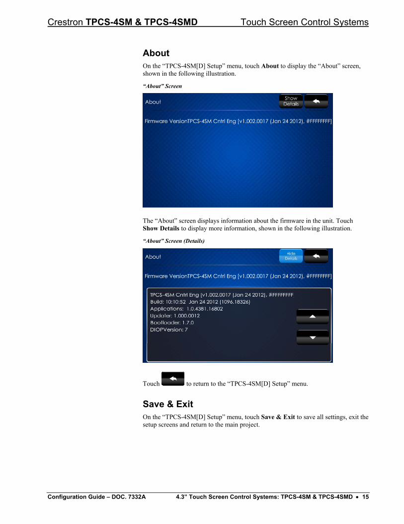
About On the “TPCS-4SM[D] Setup” menu, touch About to display the “About” screen, shown in the following illustration.
“About” Screen
The “About” screen displays information about the firmware in the unit. Touch Show Details to display more information, shown in the following illustration.
“About” Screen (Details)
Touch to return to the “TPCS-4SM[D] Setup” menu.
Save & Exit On the “TPCS-4SM[D] Setup” menu, touch Save & Exit to save all settings, exit the setup screens and return to the main project.
Configuration Guide – DOC. 7332A 4.3” Touch Screen Control Systems: TPCS-4SM & TPCS-4SMD • 15

Crestron Electronics, Inc. Configuration Guide – DOC. 7332A 15 Volvo Drive Rockleigh, NJ 07647 (2032882) Tel: 888.CRESTRON 08.12 Fax: 201.767.7576 Specifications subject to www.crestron.com change without notice.