CONDOMINIAL SEWERAGE DESIGN MANUAL - IRC · CONDOMINIAL SEWERAGE DESIGN AND IMPLEMENTATION MANUAL...
46
CONDOMINIAL SEWERAGE DESIGN AND IMPLEMENTATION MANUAL Klaus Dieter Neder [email protected] Brasília JUNE, 2000
Transcript of CONDOMINIAL SEWERAGE DESIGN MANUAL - IRC · CONDOMINIAL SEWERAGE DESIGN AND IMPLEMENTATION MANUAL...
CONDOMINIAL SEWERAGE
DESIGN AND IMPLEMENTATION MANUAL
Klaus Dieter Neder [email protected]
Brasília JUNE, 2000
2
LIST OF CONTENTS 1 – Introduction ............................................................................................................................ 5 2 - Condominial System constituent parts.................................................................................. 5
2.1 - Condominial Branch 2.1.1 - Side walk branch 2.1.2 - Back of the lot Branch 2.1.3 - Front of the lot branch 2.2 - Public sewer
3 – The Condominial System Main Characteristics................................................................... 8
3.1 - Minimum diameters 3.2 - Minimum Pipe Coverage 3.3 - Minimum depth 3.4 - Inspection devices types 3.4.1 - Pre-cast concrete inspection devices 3.4.1.1 -Inspection box with 40 cm diameter – IB40: 3.4.1.2 - Inspection box with 60 cm diameter – IB60 3.4.1.3 - Manholes – MH120 and MH150 3.4.2 – On site molded concrete inspection devices 3.4.3 - Inspection devices special elements 3.4.4 -PVC inspection devices 3.4.4.1 - PVC Inspection box with 40 cm diameter – PVC IB40 3.4.4.2 - Inspection and maintenance terminals IMT 3.5 - Household connections 3.6 - Pipes Materials
4 – Establishing the lay out of the system...................................................................................14
4.1 – The condominial branch. 4.2 – The Public sewer 4.3 – Diameter and slope options
5 – Design Parameters.................................................................................................................17
5.1 - Wastewater return coefficient (C) 5.2 - “Per-capita” water demand (q) 5.3 – Project’s horizon 5.4 - Occupation density (d): 5.5 - Population 5.6 - Infiltration rate (q. inf.) 5.7 - Systems flow (Q): 5.8 - Flow coefficients (k): 5.9 - Flow calculation (Qd): 5.10 - Infiltration flow (Qinf.)
6 - Hydraulic Calculations........................................................................................................24
6.1 - Flow conditions at a circular cross section pipe 6.2 - Flow velocity

3
6.3 - Interactive methods for the analytical calculations of circular conducts 6.4 - Limiting Velocities 6.4.1 - Minimum velocity 6.4.2 - Maximum velocity 6.4.3 - Traction tension 6.4.4 - Minimum flow 6.4.5 - Minimum slope 6.4.5 - Maximum slope 6.4.6 - Water level in the pipe 6.4.7 - Back flow control
7 - Sewercalc Spreadsheet................................................................................................................29 8 – Social Participation......................................................................................................................31
8.1 - Condominium constitution 8.2 - Condominial Branch construction
9 - Tariff and connection fee.............................................................................................................31
9.1 - Connection fee 9.2 - Service tariff 9.3 - Connection fees and tariff Policy
10 - Works Implementation...............................................................................................................33
10.1 - Knowledge of the area 10.2 - Preliminary Design 10.3 - Initial characterization of the area 10.4 - General topographical survey of the area 10.5 - Matching of the urban drawing and occupation with the topographical survey 10.6 - Community's initial mobilization 10.7 - Elaboration of a draft design of the condominial branches options 10.8 - Urban blocks individual meetings 10.9 - Adhesion term 10.10 - Condominial branch constructive design 10.11 - Community’s training 10.12 - Condominial branch construction 10.13 - Starting of the operation 10.14 - Experimental operation
11 - Implementation team..................................................................................................................36 12 – Basic design guidelines for the Pumping Stations...................................................................38 13 – Basic design guidelines for the Treatment Plants....................................................................39
13.1 - Appropriate technology 13.2 - Suggested technologies 13.2.1 - Preliminary treatment 13.2.2 - First treatment step 13.2.3 - Second treatment step 13.2.4 – Treatment Plant lay-out

4
14 – Preliminary Commercial and financial implications of the Condominial System..............44 14.1 – Connection Fee 14.2 – Tariff 14.2.1 – Operational cost. 14.2.2 – Investment recovery cost.
Acknowledgments: The author would like to thanks the all the team from the Superintendency of Sewerage Systems at Caesb in Brasilia – Brazil, whose work allowed this manual to be prepared.

5
1 – Introduction
The Condominial system is a sanitation implementation model that uses the community participation as a key element on the development of the technical solution for the system. The model is based in the ideas that appropriate technology can only be generated with the participation of the community it tries to attend, and that only trough this participation is that sustainable solutions can be achieved. The resulting Condominial system allows more flexibility of implementation, savings of up to 65% when compared to the costs of installing the conventional sewerage systems and more operation and maintenance simplicity. The Condominial System is an engineering solution based on the community participation. A condominial network can not be constructed without the community participation, because the community participation is what allows the system to be taken to its most positive solutions. When the community acts as a unit, where a collective solution is drawn in place of a individual one, the system works at its best, resulting in the best technical solution, which is usually the cheapest and simplest one.
The community participation allows a natural adaptation of the system to the most diverse existing physical and cultural conditions, which is a basic requirement in most of the periphery-urban areas of the cities, where the existent cultural situation plays a significant role in the success of a any project. Community participation is the basis of the condominial system. Through it, the proposals, ideas and solutions for the system to be implanted are put into practice, leading to its understanding and adequate use. It has the aim of promoting participation and understanding of the system’s installation process and its future operation.
From an engineering point of view, in the condominial system the sewerage network is divided in two parts, the public one, constituted by the main network, called Public Sewer, and the condominial one, represented by the Condominial Branch, which is considered the collective connection to the Public Sewer. The condominial branch basically attends what would be the smallest group of houses in a city. Called as quarter, block, or whatsoever named, in the condominial system this group of houses are linked to the main public network by a single condominial branch. In this way the public sewer only reaches the group houses, the block, in a way to receive the collective connection. It only touches the block instead of surrounding it as in the conventional system. 2 - Condominial System constituent parts
As mentioned the condominial sewerage system is divided mainly in two parts, the condominial branch itself, and the public sewer. This division can be seen as follows: 2.1 - Condominial Branch: The Condominial Branch is the pipeline that collects all the wastewater produced within a urban block. It acts as a collective connection, connecting the domestic installation of each household of a block to the public sewer that passes along the block extremity. The

6
condominial branch can be of several sorts, according to technical considerations or neighbors decision. The final lay out of the condominial branch should both obey to strict technical recommendations and be the result of the neighbors discussion and approval. The following lay-outs are the most commonly types of condominial branches used in the system: 2.1.1 - Side walk branch: Is the name given to the condominial branch when its installation is done outside of lot, under the side walk or in front of it. Usually the side walk branch is installed at a 70 cm distance of the lot limit. Is usually the most expensive condominial solution as the pipes must be well protected from traffic and the connections must have a increased extension once the connection pipe must move to outside of the lot.
2.1.2 - Back of the lot Branch: Is the branch that passes inside the lots, at their back side. This solution is usually the one that has the lowest cost, as it allows that both sides houses are connected to the same branch, meaning that the pipes extension to connect the block is minimal.

7
2.1.3 - Front of the lot branch: It’s the solution where the condominial branch passes inside of the lot, but at its front side. This solution allows a smaller depth as compared to the side walk solution, and also a smaller pipe length as the connections are done directly to the branch, without the need of any additional extensions.
2.2 - Public sewer: Is the pipeline that collects the wastewater from the condominial branches. This pipeline is always on the public area of the city. It follows the last inspection box of each condominial branch, and is installed, if possible on the side walk of the streets. When this is not possible it will be installed at the road. When the public sewer passes along the face of a Block, no condominial branches are needed at this side of the block and connection are done directly into the public sewer. With the use of the condominial system, the total length of the public sewers is drastically reduced, when compared to the traditional sewerage system. In the condominial system most of the network is made of condominial branches and only around 30 – 40 % of the system is made of public sewers. It must be emphasized that less sewers on the public areas of the city mean less risks of obstruction or damage to the system, for the condominial branches, mostly constructed in protected areas have a natural increased protection against external factors. The general lay out of a condominial system, with the condominial branches and public sewer can be seen as follows:
8
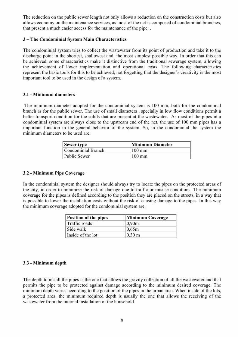
The reduction on the public sewer length not only allows a reduction on the construction costs but also allows economy on the maintenance services, as most of the net is composed of condominial branches, that present a much easier access for the maintenance of the pipe. . 3 – The Condominial System Main Characteristics The condominial system tries to collect the wastewater from its point of production and take it to the discharge point in the shortest, shallowest and the most simplest possible way. In order that this can be achieved, some characteristics make it distinctive from the traditional sewerage system, allowing the achievement of lower implementation and operational costs. The following characteristics represent the basic tools for this to be achieved, not forgetting that the designer’s creativity is the most important tool to be used in the design of a system. 3.1 - Minimum diameters The minimum diameter adopted for the condominial system is 100 mm, both for the condominial branch as for the public sewer. The use of small diameters , specially in low flow conditions permit a better transport condition for the solids that are present at the wastewater. As most of the pipes in a condominial system are always close to the upstream end of the net, the use of 100 mm pipes has a important function in the general behavior of the system. So, in the condominial the system the minimum diameters to be used are:
Sewer type Minimum Diameter Condominial Branch 100 mm Public Sewer 100 mm
3.2 - Minimum Pipe Coverage
In the condominial system the designer should always try to locate the pipes on the protected areas of the city, in order to minimize the risk of damage due to traffic or misuse conditions. The minimum coverage for the pipes is defined according to the position they are placed on the streets, in a way that is possible to lower the installation costs without the risk of causing damage to the pipes. In this way the minimum coverage adopted for the condominial system are:
Position of the pipes Minimum Coverage Traffic roads 0,90m Side walk 0,65m Inside of the lot 0,30 m
3.3 - Minimum depth The depth to install the pipes is the one that allows the gravity collection of all the wastewater and that permits the pipe to be protected against damage according to the minimum desired coverage. The minimum depth varies according to the position of the pipes in the urban area. When inside of the lots, a protected area, the minimum required depth is usually the one that allows the receiving of the wastewater from the internal installation of the household.

9
In a way to get always the lowest escavation volume, in all the situations where the natural slope of the ground is higher then the minimum required slope, the minimum depth should be adopted.
The minimum recommended depth for the pipes are as follows:
Sewer type Minimum depth Side walk condominial branch 0,70 m Front lot condominial branch 0,40 m Back lot condominial branch 0,40 m Side walk public sewer 0,80 m Traffic road sewer 1,10 m
The minimum depth for the sewers could be reduced according to conditions of the area in which the system will be installed. The suggested values are to be used in periphery areas of the cities, where mostly a definitive urbanization plan does not exist. In this case it is possible that the final urbanization levels are lower then in the systems construction time, so the adopted depth gives a safety margin for the system. In areas where definitive urbanization is established, smaller depths could be use. 3.4 - Inspection devices types The inspection devices are the elements of the sewerage network that have the main objective of allowing access to the pipeline in order to permit its maintenance in the case of obstruction. As the inspection devices allow the access to the interior of the system, they represent a vulnerable part of the system as they are a way for improper elements to enter the system causing obstruction to occur. In this way the inspection elements, called inspection boxes when installed at the condominial branches, and manholes when installed at the public sewers, should be adopted in a very conservative way, in order to reduce the risks of obstruction. The condominial system allows a significant reduction of the manholes costs because most of the pipes are of the condominial type, where the inspection boxes are very small devices located at protected areas. Also the general depth reduction allowed by the system leads to significant costs reduction.
A inspection device should be used in all of these situations:
• At the start of the branch • At each time the condominial branch reaches 60 m of length • At each time the public sewer reaches 100 m of length • At the connection between the internal installation and the condominial branch. • At any point where the pipe changes its direction or its slope • At any point where different upstream branches meet and discharge in the same
downstream branch
In a condominial system the following inspection devices are usually used:
• Sewer with a depth not larger than 0,90m, devices of the inspection boxes type with a diameter of 0,4 m.

10
• Sewer with a depth between 0,90m – 1,20m, devices with inspection boxes type with a diameter of 0,6 m.
• Sewer with a depth of more then 1,20 m, devices of the manhole type, with a 1,20m diameter inspection chamber and a 0,60 m diameter access chimney.
3.4.1 - Pre-cast concrete inspection devices. The construction of condominial systems with concrete pre-cast inspection boxes is recommended in places where PVC units are not available or to expensive in comparison to the concrete ones. The use of the pre-cast concrete devices has some disadvantages though, as they require a good construction quality control, require more handicraft for its installation and are not always water tight, what can be a problem at areas with high ground water level. The main advantage of pre cast concrete units is that they are easily obtainable, and easily replaceable in case of damage. They also have the advantage of dispensing any fitting at the connection of the pipes, as they are on site fixed with mortar. The recommended inspection devices in pre-cast concrete are the following: 3.4.1.1 -Inspection box with 40 cm diameter – IB40: This inspection box is recommended for the condominial branches, being mostly used to make the connection between the internal installation and the condominial branch. As normally the condominial branch has a depth of less then 0,90 m, this inspection box is the most used one at this kind of branch. It is made of the following parts:
• Base, where the channeling for the wastewater to flow is already cast, therefore implying in six different bases, the one with a direct flow passage channel; with a left contribution channel; with a right contribution channel; with contributing channels from both sides; a right bend and a left bend. More channel situations can be hand-crafted on site.
• Rings, that are pre-cast with several heights in order to better adopt at the local depth of the
sewer
• Cover, which must be strong enough to support the weigh of a car 3.4.1.2 - Inspection box with 60 cm diameter – IB60 This inspection box is recommended for the condominial branches with a depth of more then 0,90 m, and specially for the side walk branches, where the depth of the sewer is usually more then 0,90 m. The IB60 is made in the same manner as the IB40, only with the diameter difference.
11
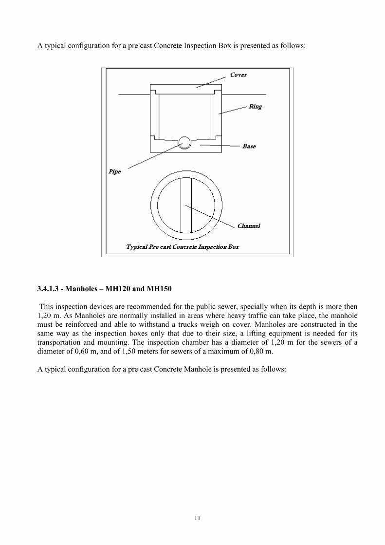
A typical configuration for a pre cast Concrete Inspection Box is presented as follows:
3.4.1.3 - Manholes – MH120 and MH150 This inspection devices are recommended for the public sewer, specially when its depth is more then 1,20 m. As Manholes are normally installed in areas where heavy traffic can take place, the manhole must be reinforced and able to withstand a trucks weigh on cover. Manholes are constructed in the same way as the inspection boxes only that due to their size, a lifting equipment is needed for its transportation and mounting. The inspection chamber has a diameter of 1,20 m for the sewers of a diameter of 0,60 m, and of 1,50 meters for sewers of a maximum of 0,80 m. A typical configuration for a pre cast Concrete Manhole is presented as follows:

12
3.4.2 – On site molded concrete inspection devices. The construction of sewers with “in situ” molded concrete inspection boxes is recommended when the diameter of the sewer is more then 0,80 m. This kind of inspection device is also designed with a inspection chamber and a chimney. The inspection chamber has a minimum internal dimension of two times the sewer diameter and the sewer is usually located at the side of the chamber, not at its center as in the pre cast manholes. The chimney has the usual 0,60 m diameter. 3.4.3 - Inspection devices special elements When the upstream segment of the sewer and the downstream segment have a significant level difference, special elements for the inspection devices are considered. The level difference can be resolved with a step, a fall pipe or with a fall pit. These elements usually represent a difficulty for the maintenance team and should be avoided at the sewer design. It is always desirable to compensate the level difference with higher slopes on the upstream segment. If this is not possible and should the need of their use arise, the use of steps and fall tubes should be on the following conditions:
• Steps, when the level difference between a upstream and downstream collector is smaller then 0,50 m
• Fall pipes, when the level difference between a upstream and downstream collector is superior then 0,50 m.
• The fall pits should substitute the fall pipes, whenever the existent fittings do not allow the execution of the fall pipe, or when the pipes have a larger diameter, starting of 0,40 m.
13
3.4.4 -PVC inspection devices. The construction of condominial systems with PVC inspection devices is recommended in places where PVC units are available and not to much expensiver when in comparison to the concrete ones. The use of the PVC devices show the advantages of being easier to install, not requiring a intensive construction quality control, making the installation quicker, and being water tight, what is a good characteristic at areas with high ground water level. The main disadvantage of PVC is that they are somehow weaker then the concrete ones requiring more attention to its protection against traffic. A important characteristic of the PVC inspection devices is that the access to the pipes has a very small diameter, usually around 10 to 20 centimeters, what almost impedes that maintenance is done by hand. This feature implies that the maintenance of a condominial system made of PVC inspection devices should be done with special equipment, as high pressure cleaning devices. The recommended inspection devices in PVC are the following: 3.4.4.1 - PVC Inspection box with 40 cm diameter – PVC IB40 This inspection box is recommended for the condominial branches, being mostly used to make the connection between the internal installation and the condominial branch. As normally the maintenance of the condominial branch should be done with adequate equipment, the could be used with no depth limitation. The PVCIB40 is made of the following parts: • Base, where the channeling for the wastewater to flow and the connection chamber are already
cast, allowing a direct flow passage channel, a left contribution channel, and a right contribution channel, with can be used by cutting the appropriate existing closed extension.
• Cover extension, for adapting the inspection box to its desired height, usually made of the same pipe used for the sewer.
• Cover, which must protected with a concrete side ring, in order to be strong enough to support
the weigh of a car 3.4.4.2 - Inspection and maintenance terminals IMT This inspection devices are recommended for the public sewer, being mostly used to substitute the concrete manholes. They have different configuration for each use, mainly the passage PIMT, that allows no connection of other sewers and the radial RIMT, that is used when two or more upstream sewer meet in the same downstream sewer. IMT’s are made of the following parts:
• Base, where the channel for the wastewater to flow is already cast. • Chimney extension, for adapting the inspection box to its desired height, usually made of the
same pipe used for the sewer.
• Cover, which must protected with a concrete side ring, in order to be strong enough to support the weigh of a car
3.5 - Household connections
In the condominial system the household connections are made in two different ways, one when the condominial branch is laid inside of the lot and the second for the side walk branch:

14
• Inside of the lot branch. In this situation the connection is always done though a inspection box, usually from the IB40 or PVC-IB40 type. The box is installed at the lot during the construction of the condominial branch and the householder is asked to do the connection when the system starts its operation.
• Side walk branch. This connection is also done through a inspection device, only with the
difference that the device is connected to trough a pipe segment to the branch that is installed outside of the lot. The inspection box is installed at the lot during the construction, when its connection to the condominial branch is done. In this case the householder is also asked to do the connection of its internal installation to the left inspection box when the system starts its operation. The connection of the inspection box to the side walk branch is done with the use of a T fitting. If a connection is to be done after the branch was constructed, a selim is to be used.
3.6 - Pipes Materials: The most used materials for the condominial system are:
Sewer type Material Sidewalk Condominial Branch PVC Reinforced Inside of the lot Condominial Branch PVC Domestic /PVC Reinforced Public Sewer φ ≤ 400mm Ceramic/PVC Public Sewer φ > 400mm Reinforced Concrete
Although the PVC pipes are usually expensiver then the ceramic ones, it is possible to compensate this disadvantage during the construction, due that the PVC pipes are easier and quicker to install. One must consider that the PVC pipes offer excellent flow conditions and are usually more water tight then the ceramic ones. On the other side, these ones offer a higher mechanical resistance. 4 – Establishing the lay out of the system 4.1 – The condominial branch. The first lay out of the system should start with the estimate of the condominial branch. For this purpose a general plant of the area, with the general topographical and urban characterization should be available. The drainage paths of the area should be identified, as the sewer is mostly to follow its same natural paths. Once the drainage paths are established, in a 1:2000 plant of the area to be attended, the designer should identify, for each block, the natural discharge point from the block, which will be mostly its lowest topographical level point. This point, where the condominial branch will probably connect to the public sewer, should be clearly market with a dot or a arrow, pointing in the direction of the flow path. At each block, based on its actual or future occupation with houses and other forms of constructions, the designer must trace the most probable lay out for the condominial branch to be constructed, and make a estimation of its length. This kind of lay out is seen in the figure below.

15
The condominial branch should be able to connect all the houses of the block. The, to this condominial branch related, number of connections must be estimated, in order that a table can be drawn, including the block reference number, its related condominial branch number, the related length of the branch and the related number of households to be connected at the condominial branch. Note that a lot can have more then one family, in the cases of multi-stores buildings and the block can have more than one condominial branch, when topography or the urban design so recommends. Once all blocks have been considered, the total condominial length and total population of the area can be calculated. This population is the saturation population for the area, and should be compared with the demographic growth expected for the area, according to item 4.5. Other types of areas, with non residential occupation must be treated at the same manner, calculating either the equivalent population or directly the resulting flow to be produced, according to item 4.9. The desired table could have the following aspect:
Condominial branches characterization Block number
Condominial branch number
Length of the condominial branch
Number of estimated households
Occupation Density
Estimated population
1 1.1 300 m 54 househ. 6 inh./househ. 324 inh. 1.2 250 m 25househ. 6 inh./househ. 150 inh.
4.2 – The Public sewer. When all of the blocks of the area are considered, according to item 4.1, the lay out of the public sewer should be drawn. The public sewer will follow the same general drainage paths, and will have to collect all the condominial branches at their discharge point, already marked with dots or arrows. The shortest path should be chosen, and a simulation exercise is recommended in the search for the best lay out solution. The following drawing is a example of a possible lay out for a generic area.

16
Once the public sewers lay out is established, collecting all the blocks and connecting them to the final discharge point, be it a treatment plant or pumping station, the designer should display all the necessary inspection devices that will be needed for the system, according to item 3.4. Each resulting segment, must be considered in a individual way. The next step is to give each segment a number. The number should be given in a upstream to down stream order, starting from the upper most stream segment from the longest public sewer, until it gets to the final discharge point, following by the second longest, and so on, until all the segments are numbered. Similarly to the table elaborated for the Condominial branch, a table must be drawn in order to tabulate the characteristics of the designed system of public sewers. At this table it is necessary to define all the contributions that are directly discharged at the segment under consideration, in order to the later calculation of the flow that will be linked with the segment. Public sewers characterization Public Sewer number
Public Sewer Length
Contributing condominial branches
Total corresponding population
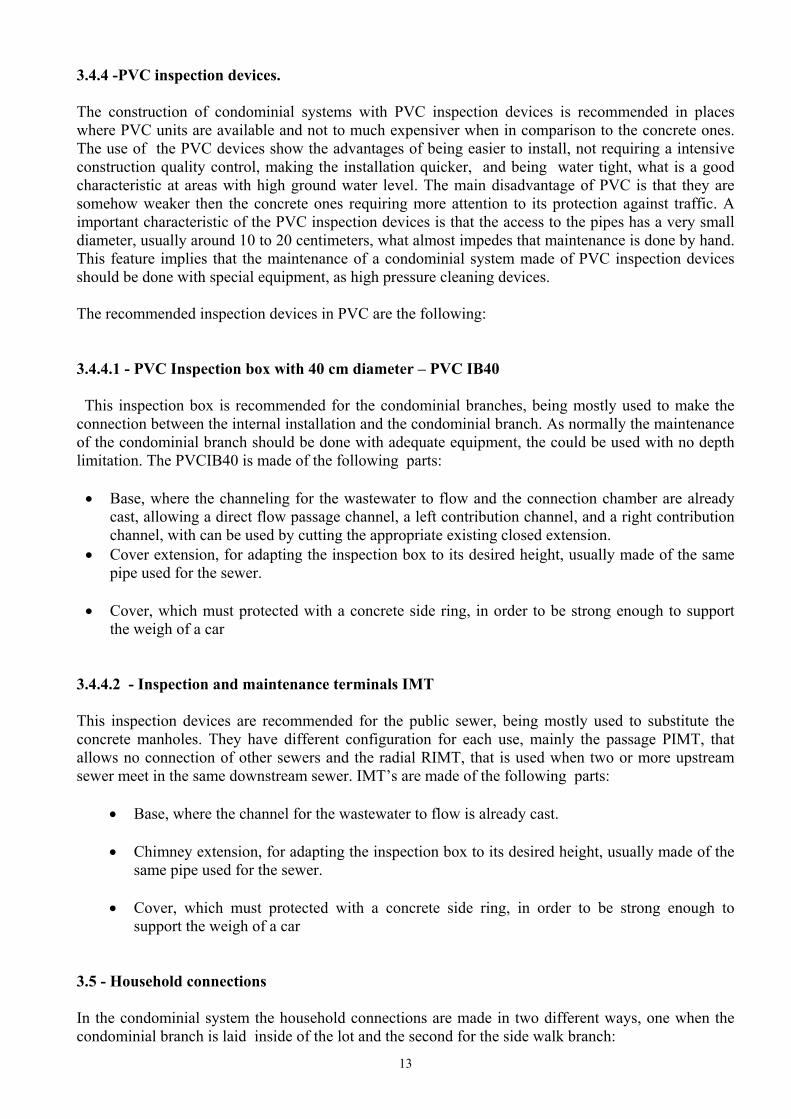
1.1 200 m 1.1 ; 1.2 474 inh. After the segments are tabulated, the flow for each segment should be calculated, according to item 4.9. Special attention should be given on consideration of the upstream segments, as the flow of each segment should be the sum of its own contribution added to all upper stream segments contributions. When this is done, the designer should proceed the hydraulic calculations, in order to define the diameter and the slope for all segments. After the diameter and levels calculation, all the information should be drawn in the project, informing the diameter, the slope, and the related to the manholes number, ground level, pipe level and manholes depth. A typical segments drawing has the following representation.
17
4.3 – Diameter and slope options For the condominial branches, as a general rule, the slope of 0,5% and the diameter of 100 mm are adopted for all the branches. In this way, no hydraulic calculation is done for the condominial branches. A different slope is adopted only when the natural terrain slope is higher than the minimum slope, so the natural terrain slope is adopted, and a larger diameter would only be necessary if the condominial branch would connect more then 300 houses, fact that in a single block is almost impossible to happen. For the Public sewer, when calculating the first segment, one should start with the minimum depth that is necessary to connect the related condominial branches, so that the connections are guaranteed. For this, a evaluation of the discharge depth of each related condominial branch must be done, according to the adopted minimum slope and the topography of the area. The designer can consider a upstream depth for the condominial branch of about 40 cm. Once the starting upstream depth is defined, the designer must calculate the downstream depth of the segment, using the minimum slope, when the natural terrain slope is smaller than the minimum pipe slope, or the minimum depth, when the natural slope of the terrain is larger than the pipes desired minimum slope. After deciding the slope of the pipe, and establishing the depth of the downstream level of the segment, the diameter calculation can take place, based on the maximum flow to be conducted by the segment and the adopted slope. Usually the diameter is a consequence of the adopted slope, but, in some cases, the slope can be changed to satisfy a desired diameter. To each of the systems segments, the above procedure must be taken, remembering that each segment downstream level is the next segment upstream level. This procedure can automatically be calculated through the SEWERcalc spreadsheet provided by the author The values to use in the above mentioned procedures and calculations are explained in detail in the following items. 5 – Design Parameters Not only the physical characteristics of the condominial system are distinctive, but also the design criteria and design parameters try to result in the optimization of the system. The choice of the design parameters has a significant impact on the systems cost, as they will define the size of the system to be constructed. In a scenery where the demand to increase the basic sanitary services, as seen in many parts of the World , is much larger than the available financial resources, it is important to maximise
18
the use of these resources, constructing systems that are designed for the real demand they should attend. Conservative design parameters mean to construct systems that won’t be used at its full potential. In a situation where many won’t have any services at all, design parameters should be as close as possible to reality, based if possible, on the observation of the reality to be attended. The following discussion highlights some aspects related to the design parameters that should be used in a condominial project. Although the hydraulic design in nothing differs from the usual design, some criteria are specially important in the condominial system and will be emphasized as follows: 5.1 - Wastewater return coefficient (C) The wastewater return coefficient tries to represent the relationship between the water consume in a household and its correspondent wastewater production. The value of the wastewater return coefficient is usually less then one, and for the design a traditional value of 0,8 is adopted. Recent experiences in Brazil show that in the periphery of the large urban areas the return coefficient is lower than the value traditionally used in the design of the projects. Values of the order of 0,65 seem to be common in systems of sewers implemented in low income areas and they could be used in future projects. In areas where available connections are linked with a wastewater treatment plant, the project should give importance to evaluate this item, trying to look for the real coefficients that are being experienced, in order to consider this experience in the design of the system. When no data is available, the traditional value of 0,8 should be used.
5.2 - “Per-capita” water demand (q): The per - capita water consumption of a population depends on several factors, including cultural tradition, economic level, urban characteristics, climate, etc. The choice of the per person daily water demand should be preceded of extensive evaluation of the conditions verified at the place that one will assist. At the low income areas that the condominial system is usually implemented, all the conditions tend to indicate a low value for the water demand. A value of 120 litters per inhabitant per day should be the maximum consume to be considered, and is still very high on many situations around the world. This value is usually used for periphery areas in cities of hot climate and that show culture of high levels of water use. It is also important to see that average per capita consumption considered in many projects reflects the average generally verified consume at the entire city, so that the per capita, when verified exclusively for residential areas, tends to be on a lower level. Experiences have been showing that real consumption’s on the order of 80 litres per inhabitant per day are common in periphery urban areas and it seems that a value of this order would be acceptable in the residential areas of low income level. It is important that the project evaluates this subject in a detailed matter, in order to size the system according to the real demand it will attend. When water supply is already present in the area to be attended, and controlled trough household meters, the existing water demand should be checked. Only to offer some orientation for the design of the condominial system, the following consumes could be considered as a first reference to the discussion of the “per-capita” water consume:
C = 0,80

19
Type of urban area according to income level PER-CAPITA –(q) (l/hab.dia)
- High 250 - Medium 180 - Low 100
5.3 – Project’s horizon The horizon of the project establishes the time in which the constructed system should be able to support the growth of the population of the area to be attended. If the horizon of a project is short, the system will result less expensive to implant, but could demand new investments to follow the populations growth. On the other hand, a project with a long horizon will cost more in the implantation phase, but would be over dimensioned for a long time. As condominial systems are usually designed in low income areas, where the demand on services is larger then the resources available to attend them, is a good strategy to shorten the horizon of the project. In this situation it is more advisable to reduce the horizon of attendance of the systems, in way to allow the reduction of its implementation cost and to allow to assist, in a short term, a larger population. It is not justified to design systems to assist to future generations while portion of the current generation still rests without attendance. This discussion tries to highlight that the planners certain reluctance in projecting systems with shorter project horizons doesn't make sense in a picture of lack of resources, where the demand is larger than the offer. In a condominial system, specially in low income levels, a project horizon of a maximum of 15 years is recommended.
5.4 - Occupation density (d): On the condominial projects it is common to count the population to be attended based on the number of existing lots on the blocks where the condominial branch will be designed. In this case it is necessary to establish a population density, that represents the number of people that live in a household. This number varies according to the income level of the population. On high income level areas the number of people in a household can be as low as 4. In low income areas this number can be as high as 10. This value is achieved when more than one family lives in the same lot, a very common situation in the poor areas of the cities.
Only to offer some orientation for the design of the condominial system, the following values could be considered as a first reference to the discussion of the occupation density to be adopted:
Type of urban area according to income level
OCCUPATION DENSITY (d) (inhabitans/household)
- High 4,50 - Medium 5,50 - Low 7,00
Project horizon = 15 years

20
These values should only be adopted if no survey is available for the area to be attended. 5.5 - Population In order to get a good approximation between the design value and the future demand, the determination of the population to be attended by the project should be based in, at least, two principal studies.
• The first study should emphasise the occupation density for the several considered lots to be attended, which should be based on a population census of the studied area. When not available, census done in areas similar to the one that will be studied can be used. This value should be used according to the occupation codes for area, with are generally determined by the city hall. In this case the number of inhabitants should be lifted for each considered lot, among residential, single or multi-familiar lots, and for general use lots, that can range from public equipment to industrial use. The resulted value is the urban saturation population of the area.
• The second study is related to the growth curve of the population that one can expect . This
curve, in the horizon considered for the project, will define the value of the population to be considered, if it would continue growing in the same considered area, without the consideration of the urban design limitations. The growing rate of the population should consider that the large expansion rates verified in periphery urban areas are normally related to a large horizontal expansion, and shouldn’t be used as a growing rate for internal areas of the town. The vertical growth of the considered area is usually much lower than the average growth of the city as a hole.
The population adopted for the design should be a careful compromise between both studied values, usually considering the lower value for treatment plants and the larger to the network design. The points above discussed, show that the three items, per capita demand, return coefficient and design population have a fundamental importance in the design of a system and should be considered in agreement with the particularities of each area to be attended. For the networks a more conservative design strategy is acceptable, even if this implies in wider horizons of project. In this case it would be adequate to maintain a margin of safety in one or two of the discussed parameters, but never in the three of them. For the case of the treatment units, units that can easily be constructed in modules, it is advisable the use of more realistic parameters, in a way not to imply in unnecessary investments, result of the of the over-dimensioning of the unit. 5.6 - Infiltration rate (q. inf.) According to the Brazilian Standards, on the design of a sewer system, a infiltration rate should be added to the wastewater flow, with a value that tries to reflect the type of pipes to be used, the general soil condition, the ground water level, the types of manholes and inspection boxes to be used. The suggested values for the infiltration rate range between 0,05 a 1,0 l/s. km.

21
In the condominial system the value to be adopted depends on the type of material used in the system, for PVC system can be made water tight, the infiltration rate for this kind of material is considered zero.
Sewer Material Infiltration rate Ceramic or concrete 0,2 l/s. km PVC 0,0 l/s. km
5.7 - Systems flow (Q): For the determination of the design flow for the system, two values of contribution should be considered:
• The initial flow (Qi): with base in data and studies of current consumption of water, when a verification for the minimum flow should be done;
• The final flow(Qf): with base in estimates for the population at end of the project horizon
period. This values should be calculated for the residential areas of the project and added of the concentrated flows produced by industries, commercial buildings, schools and other facilities that present higher levels of water consumption when compared with the domestic ones. This contributions should have their flows quantified and considered as point sources for the effect of sewer design. 5.8 - Flow coefficients (k): As the flows determined by the water consume is a average value, the actual design of the system should consider the flow coefficients that try to correct these values to approximate the design flow to the values that will take place during the operation of the system. The flow coefficients are used to calculate the maximum and minimum flow that will occur in the pipe. The usually used coefficients are: Coefficient k1. Represents the relationship between the medium flow of the day of larger contribution and the annual daily medium flow (corresponding to the coefficient of daily variation):
Coefficient k2. Represents the relationship between the hourly maximum flow and the medium flow of the day of larger contribution (corresponding to the coefficient of hourly variation):
Coefficient k3. Represents the relationship between the minimum flow of the day and the medium flow of the day of medium contribution (corresponding to the coefficient of minimum hourly variation):
k1 = 1,20
k2 = 1,50
k3 = 0,50

22
5.9 - Flow calculation (Qd): For the determination of the flow to be used to design the sewer, the following formula should be used for residential areas:
Where: Qd = Flow ( liters / second ) N = Number of households attended by the sewer, including those of upstream
branches (units) D = Occupancy density (inhabitants/household) q = “per capita’” water demand. ( liters / inhabitant. Day ) C = return coefficient. k1 = Day of largest consume coefficient. k2 = Hour of largest consume coefficient.
For the flows produced by industries, commercial buildings, schools and other facilities that present higher levels of water consumption, point flow inputs should be considered. When specific data is not available, the following general flow values can be used for the design of the system:
Type of utility Wastewater flow (l/s) Police station 0,045 Regional Administration 0,117 Supermarket 0,316 Church 0,077 Regional activity center 0,053 Bank 1,620 Military station 0,769 Kindergarten 0,088 Professional school 0,220 Commerce unit 0,048 Gas station 0,120 Post office 0,089
For empty areas, where no precise urbanization is defined, it is common to use a area based value, which should express the general urbanization tendency for the area. When specific data is not available, the following general flow value can be used for the design of the system:
Where: A = area in hectares.
Qd = N x D x q x C x k1 x k2 86.400
Qi Cx xAxk xk= 0 3 1 2,

23
5.10 - Infiltration flow (Qinf.) When the used pipe material so requires, the infiltration flow should also be added to each branches flow:
Where: q.inf. = infiltration rate L = Length of the upstream sewer.
6 - HYDRAULIC CALCULATIONS The following procedure follows the Brazilian Standards for sewer design NBR 9649/86. The sewerage pipelines are normally designed as free conducts with a circular cross section. Exceptionally one can use pressurized pipes together with pumping stations or with the use of siphons. As free conducts, gravity induced flows are calculated to flow at a maximum cross section of 75% of the pipes area. This condition should be obeyed on the maximum flow at the end off the horizon period. The flow condition is admitted, for the calculation to be made, in a constant and permanent regime. All contributions are considered at the upstream inlet of the pipe. 6.1 - Flow conditions at a circular cross section pipe The flow in a free conduct in a permanent and uniform condition satisfies the two following
equations, where the impulse transmitted for the liquid is originated by the gravity force Bernoulli equation:
Where: Za e Zb = Conduct coordenate. Va e Vb = Flow velocitu on sections a and b . Ya e Yb = Liquid water level. Hf = Head loss In a condition of permanent and uniform flow Va = Vb , Ya = Yb, so:
Continuity equation:
Qinf. = q.inf. x L
Za + Ya + V2a / 2g = Zb + Yb + V2b / 2g + hf
Za = Zb + hf
Q = Va x Aa = Vb x Ab

24
Where: A = Area of the flows cross section (m2) V = Average velocity on the section (m/s) Q = Flow (m3/s)
Geometric and trigonometric relations of the circular cross section elements The elements of a circular cross section are calculated according to the circular segments, the circumference arcs and trigonometric relations.
Complement of the angle of the circular arc in radians:
Whitch should be limited to the interval 1,59 rad ≤ θ ≤ 4,43 rad, where, 0,15 ≤ Y/D ≤ 0,80.
Wet area
Wet perimeter:
Wet with or wet string:
θ = × −
2 1 2arc
YD
.cos.
( )AD
= −2
8θ θsen.
PD
=θ2
b D=sen.θ
2

25
Hydraulic radius:
Obs.: Same for ½ section or full section.
6.2 - Flow velocity The velocities can be calculated with the following formulas: Manning Due to its simplicity and the large quantity of experimental data, the Manning formula is the most used formula when designing sewer pipes.
Where: V = velocity m/s. n = roughness coefficient, usually adopted as 0,013 for sewer pipes Rh = hydraulic radius (m). I = slope of the segment (m/m).
Chezy:
Where: V = velocity m/s. Rh = hydraulic radius (m) I = slope of the segment (m/m) C = Chezy coefficient, which can be determined by numerous formulas.
Suggested is to use the Bazin formula, where, C mR
=+
87
1 , where m = 0,16 for any kind of
material.
Manning modified by Macedo:
Where n = 0,013, being valued for the0 15 0 80, ,≤ ≤YD
interval.
6.3 - Interactive methods for the analytical calculations of circular conducts: The dimensioning of a sewer pipe is done in relation to, for a given flow, a chosen slope and diameter, the resulting water level in the pipe. This water level should not be higher then the
RD
= −
41
senθθ
Vn
R IH
= ××1 2 3 1 2/ /
V C R IH= ×
V Q I= × ×15 8 1 4 3 8, / /

26
established design limit. The calculation is possible to be achieved using a graphic or through a interactive calculation. This last one can be improved on a electronic programmable calculator or with a electronic spreadsheet
For the interactive calculation the most used methods are the linear interaction method and the Newton-Raphason method. This last one is more used due to its converging properties ad application simplicity.
Using the Newton-Raphason method, the equation that expresses the flow conditions in a permanent and uniform flow condition, and that can be solve interactively is.
θ θθ θ
θ
θ
θ= −− ×
− − ×
−
− −
−
0
0 02 6
0 6
04 6 1
0 6
2
1 2 10
1 60
0 4
1 60
0 6
sen
cos
,,,
,,
, ,
, ,
nQInQI
D
D
For a flow on a critical condition de equation to solve is the following:
θ θθ θ
θ
θθ θ
= −− −
− −
−
−−0
0 0
2 1 35/3 0
1 3
0
2 1 35/3 0
2 30
82
143 2 2
c
c cc
cc c
Qcg
D
Qcg
D
sen sen
cos cos
/ /
/ /
6.4 - Limiting Velocities 6.4.1 - Minimum velocity The sewer should be designed with a flow velocity that is able to carry all the solids that usually are present in domestic wastewater.
The minimum velocity is the one that guarantees that the sewer has a self cleaning flow that occurs at least one time in a day. The self cleaning capacity is related to a minimum water level in the pipe, meaning that for same flow values, smaller diameters can have better self cleaning capacity. The minimum recommended velocity is 0,6 m/s.
The best parameter to measure the self cleaning ability of a flow in a pipe is to determine the traction tension that the flow causes. This tension is defined as the tangential force that is applied to the pipes wall by the flowing liquid. 6.4.2 - Maximum velocity The maximum velocity is established to impede that the liquid causes the pipe wall to erode, due to the solid particles that are present in the wastewater. The recommended maximum velocity is related to the type of material used in the pipe, and can be adopted as follows:
Material maximum velocity (m/s) Ceramic 5,0 Concrete 4,0 PVC 6,0

27
6.4.3 - Traction tension This parameter measures the capacity of the flow to carry the solids. It is related to the specific weight of the wastewater, to the hydraulic radius and to the slope of the sewer. The sewer pipes are verified with this parameter in order to establish the best economical solution for the system. It leads to smaller slopes then the resulting from minimum velocity considerations, and in this way leads to less expensive solutions. The traction tension is calculated with the following formula: Where: = Average traction tension ( Pa ) = water specific weight ( 104 N/m3 ) Rh = Hydraulic radius ( m ) I = Segment slope ( m/m ) The evaluation of the sewer segments is done so that the minimum value for the traction tension is τ = 1,0 Pa (0,10 kg/cm2). This value must be achieved for the initial flow condition (Qi), adopting Manning roughness coefficient of n = 0,013. 6.4.4 - Minimum flow The small flows that occur at the condominial branches when calculated on base of a daily base are generally to small to offer a proper solids transport capacity, specially on low sloped pipes. In practice, however, it is verified that a single toilet flush is able to produce a flow of about 1,5 l/ s, which is enough to have the sewer washed. In this way, the minimum flow to be considered when designing the system is 1,5 l/s, a value also recommended by the Brazilian standards - NB 9649/86.
Were Qmin. is the minimum flow 6.4.5 - Minimum slope According to the cited Brazilian standards, the minimum slope that should be adopted for the design of the system is given by the following formula:
Were Q is the flow (l/s) Imin. Is the minimum slope (m/m)
So, for the minimum recommended flow, that usually occurs at the condominial branches, the minimum slope should be:
Were Qmin. is the minimum flow (l/s) Imin. Is the minimum slope (m/m)
τ δ= × ×R Ih
Qmin..= 1,5 l/s
IMIN.= 0,0055 x Q-0,47
IMIN.= 0,0045m/m
28
For constructive reasons the adopted minimum slope for the condominial branches is 0,5%, 0,005 m/m.
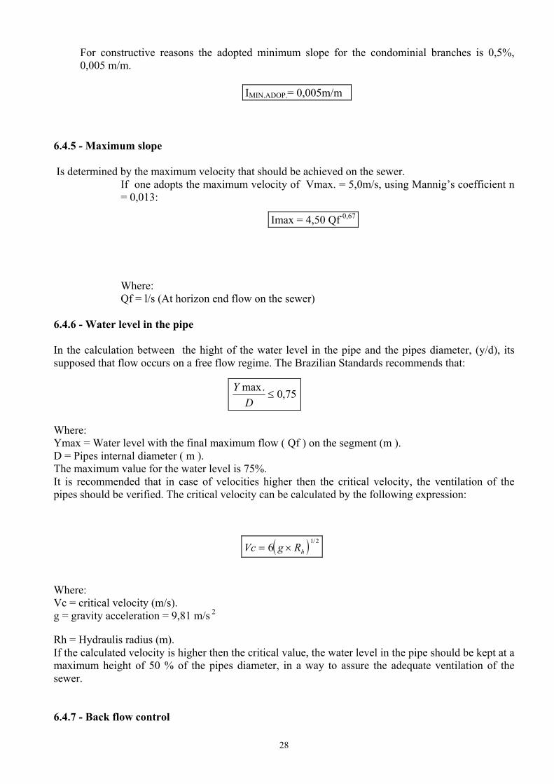
6.4.5 - Maximum slope Is determined by the maximum velocity that should be achieved on the sewer.
If one adopts the maximum velocity of Vmax. = 5,0m/s, using Mannig’s coefficient n = 0,013:
Where: Qf = l/s (At horizon end flow on the sewer)
6.4.6 - Water level in the pipe In the calculation between the hight of the water level in the pipe and the pipes diameter, (y/d), its supposed that flow occurs on a free flow regime. The Brazilian Standards recommends that:
Where: Ymax = Water level with the final maximum flow ( Qf ) on the segment (m ). D = Pipes internal diameter ( m ). The maximum value for the water level is 75%. It is recommended that in case of velocities higher then the critical velocity, the ventilation of the pipes should be verified. The critical velocity can be calculated by the following expression:
Where: Vc = critical velocity (m/s). g = gravity acceleration = 9,81 m/s 2
Rh = Hydraulis radius (m). If the calculated velocity is higher then the critical value, the water level in the pipe should be kept at a maximum height of 50 % of the pipes diameter, in a way to assure the adequate ventilation of the sewer.
6.4.7 - Back flow control
IMIN.ADOP.= 0,005m/m
Imax = 4,50 Qf-0,67
75,0.max≤
DY
( )Vc g Rh= ×61 2/

29
Always when, due to a slope reduction, the water level on the downstream segment is higher the the upper stream one, the back flow possibility should be avoided. In this case the use of a down step is recommended. This step can be calculated with the following expression.
Where: Y2 /D = Water level on the down stream segment D = Down stream segment diameter y1 /d = Water level on the up stream segment d = Up stream segment diameter. 7 - SEWERCALC SPREADSHEET
For a preliminary design of the sewer system, the author provided a spreadsheet to do the basic calculations necessary to the dimensioning a sewer system. The spreadsheet allows to do the hydraulic dimensioning of the pipes, according to the topography of the area to be attended, and produces also the basic quantities necessary for a preliminary cost estimation for the services. To use the spreadsheet SEWERCALC, it is necessary to, first, ordinate all the segments of the system, in a upstream to down stream order, starting from the main collector, the more extensive one.
rYD
DYd
d= × − ×2 1

30
In the above example the data input will be made in the following order:
Item Segment 01 1-1 02 2-1 03 3-1 04 2-2 05 1-2 06 4-1 07 5-1 08 4-2 09 1-3
Sewercalc has two internal spreadsheets types. The AREA spreadsheet, that allows to calculate the population and flow that is contributing to each segment of the sewer system and the Sewercalc itself, that does the hydraulic calculation. a) The following fields should be filled when using the SEWERCALC spreadsheet: b) Area name; c) The basic design parameters; d) Segment number. Must be filled with the same number as used in the AREA spreadsheet, so the
program can find the length and the flow of the segment. e) Contributing population. When not already informed in the AREA spreadsheet, the number of
inhabitants or number of lots should be informed in this field. Only one of these information should be used.
f) Upstream contributing segments. Should be filled with the reference number of the upstream segments that directly contribute to the considered segment
g) EXAMPLE: For the above shown sewer, the following contributing flows should be indicated:
For segment 2-2 ............... Contributing segments 2 e 3; For segment 1-2 ................ Contributing segments 1 e 4; For segment 4-2 ................ Contributing segments 6 e 7; For segment 1-3 ................. Contributing segments 5 e 8.
h) Upstream and downstream of the considered segment land levels; i) Upstream segment level:
- Calculated. This field shows the calculated upstream segment level, according to the minimum adopted depth and the upstream, downstream sewer levels already established.
- Step. To be filled when a step is desired, with the step height. - Adopted: Should be the result of the calculated level minus the adopted step height.
j) Downstream segment level:
- Calculated: This field shows the calculated upstream segment level, according to the minimum adopted depth and the adopted slope.
- Adopted: Is usually filled with the same level as the calculated one. If for any reason must
be considered different then the calculated one, should be filled with a new value. k) Diameter calculation

31
8 – Social Participation 8.1 - Condominium constitution. One of the first questions that a Condominial program must face, regarding the social activities it will promote, is the one related to the desired level of organisation that the community of each block will be encouraged by the program to perform. There might be the need of a strong organisation, in terms of a documented association, in order to keep the neighbours united by a formal term, or just the normal participation in the programs activities could be enough for the success of the project. The Condominial System faces a very strong relationship with the community it will attend. One must see that the usual communities of low income areas are young communities, in the sense that most of the people are recently originated of rural areas, with a small level of communal organisation. Therefore it could be important that the project tries to stimulate social organisation, as a key role for its success. In this way the program must decide on the need of a formal organisation for the blocks to be attended, usually called as condominiums. In the condominial model, the condominium has a strong role in the process, as the condominial branches can be considered a private good, for which the owners are also responsible for the construction and maintenance of the system. On the other hand, when one moves to a situation where the inhabitants have a longer tradition in living in urban areas, and a stronger natural bond to each other, it is possible that the condominial turns to be more a technological option for the expansion of the coverage, and social organisation may be left as just an option for the inhabitants. The continuity of the condominium, informal or formalised, is left at the neighbours convenience. In this action form, the unit of attendance for the service provider continues being each inhabitant's individual residence. It is common that the social activities related to the condominial system stimulate the forming of leaderships at the blocks it is working, as it is natural to chose one representative of each block to take care of the activities that will be taken within the program. In this case, care must be taken in order that this does not politicise the process. The experience in the implementation of the condominial system in more politically involved places, demonstrated that a delicate political balance generally exists among the involved communities and that the fomentation of organisation, with the stimulation of the creation of new leaderships, may end up polarising the process, with damage in the course of the works. In these situations the work becomes politicised, and the acceptance or condemnation of the service depends on the political party indirectly associated to the work. 8.2 - Condominial Branch construction The condominial model accepts that the neighbours participate actively during the construction of the condominial branch, even doing the construction by themselves. This option represents a significant economy at the investment costs, as a significant part of the investment is eliminated trough the work of the inhabitants. Experience shows that for several situations the inhabitants will prefer that the service provider execute the construction of the condominial branches. This is especially true when the population has a higher income level, and somehow is integrated to the work market of the city. In this way the self construction should be a choice for the involved community, and in no way should be imposed by the program. 9 - Tariff and connection fee 9.1 - Connection fee
32
A connection fee politics must be established before the start of a condominial program. Usually the connection fee is related to the type of condominial branch the neighbours have chosen, and its cost should reflect the cost of the chosen option. This is one of the main ideas of the condominial system, as the amounts paid by the neighbours should be directly related to the cost of the system. In a general way, the condominial system considers that the condominial branch is a private part of the system and its cost is to be covered by its owner, that is, the neighbours of the condominium. In this way the connection fee should mostly equal the construction cost of the condominial branch. 9.2 - Service tariff Service tariff should cover the maintenance of the system, executed by the service provider and the recovery, in a long term range, of the investments required to the construction of the system, with exception to the condominial branches, which are paid by the connection fees. In the condominial model one tries to do a relationship among the inhabitants' option, with its implementation and operation costs, and the connection rate and the tariff that these same inhabitants will pay along the use of the system. A wide range of options should be given to the inhabitants, where, in one extreme the neighbours construct and maintain the system, and in the other, all service is done by the service provider. In this optics, even the equivalent option to the conventional system should be offered to the inhabitants, which would be the use of the walk extension with the integral maintenance on the part of the service provider. It is important that in the works of community mobilisation, the costs of the tariff are explained in full detail, also presenting the other components of the system ( public network, treatment plants, pumping plants, etc. ), as in relation to the total investment for the implementation of the whole system, still represent most of its cost. 9.3 - Connection fees and tariff Policy For the connection fee, the condominial system doesn't foresee any payment in the form of a “connection right”, restricting itself at the effective cost of the extension, including the financial costs of the construction by the service provider. For the definition of the value of the tariff, one should consider the costs of materials and services employed in the remaining works of the system, including the main nets, pumping stations and treatment plants, the operation and maintenance costs, and the cost related to the administration of the system and more the responsibilities owed to its financing to the user. As the condominial system admits the user's participation in the maintenance of the branches, this cost should be considered in the calculation of the tariff, allowing its reduction for the user. To exemplify, when the user assumes the maintenance of the branch, he is assuming about 60 to 70% of the cost of maintenance of the nets, what should reflect in about 30% of reduction in the cost of the tariff. It is important that the user receives the benefits obtained by the use of a reduced cost system. As sanitation is a monopoly, be private or public, its exploration should be object of control and for so much, the existence of a regulatory agency is of fundamental importance, to establish and to control the quality and cost of the services. So that the regulator agency can act, real costs should be verified for the Sanitation services, in a way to guide the process of control of the activity. Any program for implementing a condominial system should try to produce, besides the operational and construction costs; also those related for administration and return rates, in a way to establish a reference mark for future projects. The program should discuss the economical and financial sustainability of the proposed systems, including costs indicators for construction, maintenance and administration, with their consequences on the tariffs and connection rates. Suggestions should be given for the financing possibilities, proposing a rational package where the investment costs are shared among the possible

33
participants (International agencies, central government, local government, service providers and users); 10 - Works Implementation For the implementation of all the sewer, including the condominial branches and all the social work, the following methodology and activities will have to be considered by the project: 10.1 - Knowledge of the area Several information are needed to define the project area, the following list should be available for a proper knowledge on the area to run the project:
- Physical boundaries of the area - Topography of the area - Blocks identification - Urban design, actual and for the future. - Population to be attended – actual and at the projects horizon - Storm water paths of flow - General income level - General cultural level - Hygienic habits - Actual water consume - Actual sanitation procedures - Potential for social participation - Demand for sewer construction - Paying willingness for the service
10.2 - Preliminary Design
The preliminary design of the system has the objective of clearly establishing the main technical aspects of the system to be constructed, providing all the basic information necessary for the later executive construction design. As usually a project doesn’t represent a master plan for the city it will be attending, it is recommended that the project considers a complete local solution for the collected wastewater, that could be easily integrated in a metropolitan sewerage plan. In this case the Project must define not only the lay out of the sewers, but also location and type of pumping stations and treatment facilities. Some additional information will be needed to develop the preliminary design of the system. The following list should be available at the start off the study:
- Actual and future water demand - Residential and non-residential users - Expectation of wastewater return coefficient - Expectation of infiltration rates - Preliminary topographical definition
34
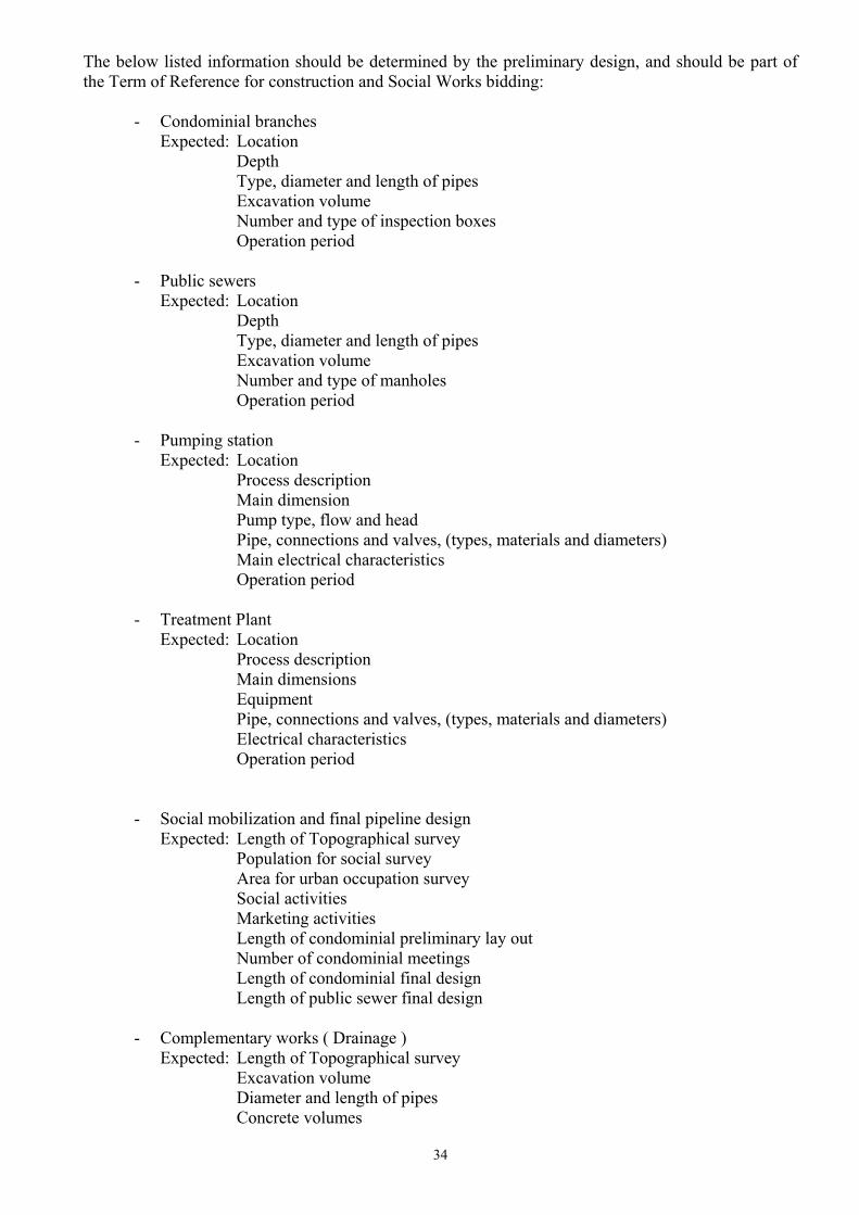
The below listed information should be determined by the preliminary design, and should be part of the Term of Reference for construction and Social Works bidding:
- Condominial branches Expected: Location
Depth Type, diameter and length of pipes
Excavation volume Number and type of inspection boxes Operation period
- Public sewers Expected: Location Depth
Type, diameter and length of pipes Excavation volume Number and type of manholes Operation period
- Pumping station Expected: Location
Process description Main dimension
Pump type, flow and head Pipe, connections and valves, (types, materials and diameters) Main electrical characteristics Operation period
- Treatment Plant Expected: Location
Process description Main dimensions
Equipment Pipe, connections and valves, (types, materials and diameters) Electrical characteristics Operation period
- Social mobilization and final pipeline design
Expected: Length of Topographical survey Population for social survey Area for urban occupation survey
Social activities Marketing activities Length of condominial preliminary lay out Number of condominial meetings Length of condominial final design Length of public sewer final design
- Complementary works ( Drainage ) Expected: Length of Topographical survey Excavation volume Diameter and length of pipes Concrete volumes

35
10.3 - Initial characterisation of the area. This activity must produce the first initial survey of the area to be attended, in order to get the necessary information for the beginning of the works, including the characterisation of the urbanisation, the existent constructions and its occupation. It also does researches on the socio-economics of the population. It is advisable that the people that work in this survey are the same ones that are going to work with the community, so that they slowly begin to understand the cultural characteristics of the people and the physical characteristics of the city. One must note that the team that will be working on the project must have a special approach to the work, as it will be common to work on nights and weekends on a schedule that must follow the neighbours availability to discuss the project. 10.4 - General topographical survey of the area This work should leave reference levels in all the urban blocks to be attended by the system, for the future use of the construction teams. 10.5 - Matching of the urban drawing and occupation with the topographical survey Should produce the urban–topographical plants of the area, including all the constructions, urbanisation, public devices and important information for the project. In this survey the existing maps should be checked, in order to include the new constructions and irregular occupation. This work must include the survey of existing storm water sewers ( that can easily be detected by the manholes) and channels 10.6 - Community's initial mobilisation. This activity starts through contacts with the community leaderships, existent representation organisations and people in general. In this first step of the social works the program is presented to the people, with its characteristics and the community's role in the program. It is recommended that a intensive marketing of the project is done in the area, including schools, popular radio stations, communal activities, folders, etc., so that the people of the area really get involved with the program. Children and women should play a key role in the hole process. 10.7 - Elaboration of a draft design of the condominial branches options According to the preliminary design of the system that was made during the planning phase and the data acquired by the already done urban–topographical plants of the area. This options will be presented to the neighbours at the condominial meeting. 10.8 - Urban blocks individual meetings After the community’s initial mobilisation, individual meetings with the inhabitants of each existing urban block might take place. At this second level of participation, the model of implementation of the condominial system is presented in details, and the people start discussing the available engineering
36
solutions for the branches that will be built. General aspects of public health and sanitary education are also discussed at this level, emphasising the aspects related to the success of the program, including related problems with storm water and garbage management. 10.9 - Adhesion term During or after the meeting, the neighbours should choose the definitive layout of the condominial branch that will attend their block, together with the cost implications that this option will imply. This decision should be documented by the mean of a “Adhesion Term”, which is a formal acceptance by the neighbours of the construction of the system and the fees and tariffs related to the made choice. 10.10 - Condominial branch constructive design With the adhesion of the neighbours, the executive project of the condominial branches can be done. The public sewer design is also finished at this step of the project, matching its final design with the detailed condominial branch. 10.11 - Community’s training When the construction of the branch is overtaken by the neighbours, its time to have the preparation and community's training for the construction of the works. This step involves constructive and maintenance aspects of the system. The project should provide the materials and technical supervision for the construction, specially regarding the laying of the pipes and connections. 10.12 - Condominial branch construction When the construction is done by the contractor, after the executive design is ready, execution may proceed starting from the condominial branch and following by the public sewer.
10.13 - Starting of the operation The system will only start operation when the whole sewer and treatment plant are ready. This means that the population must be aware that the connection will take some time to be implemented. 10.14 - Experimental operation After the system is ready and connections are made, a special monitoring of the operation should be done through a period of three months. 11 - Implementation team When considering the implementation of a condominial program, one must see that a adequate number of prepared people are to be in charge to the system. As the condominial system has a proposal of a great approximation with the reality it will work with, be it on the social or technical side, one must consider that a larger team is usually necessary, as when compared to the traditional sewer system. The cost of the additional staff is compensated by the social and economical advantages that the system results. For a condominial program to be implemented, the following team should be considered as necessary for the works to be accomplished:

37
- Technical co-ordination team. Responsible for the co-ordination of all the technical works and general planing / co-ordination of the program, generally constituted by the service provider personnel, with the following people involved:
- 1 general co-ordinator, responsible for the general strategy of the program; including the managerial general monitoring of the activities. - 1 field co-ordinator, responsible for the general co-ordination of the field works, involving the planning of the activities; the control and administration of materials; the integration of the works with the service provider, the co-ordination of the field teams involved in the project and the community participation. - 1 design co-ordinator, responsible for the design of the sewers networks, including the condominial branches, public sewers and foreseen units of wastewater treatment; elaboration of the, for the works, necessary materials lists, elaboration of technical and constructive details and for resolving the design problems verified in the works. - 1 social works co-ordinator, responsible for the co-ordination of all social activities, including the definition of procedures, planning of activities, control of results and co-ordination of the field team - 1 communication co-ordinator, responsible for the social communication activities, preparation of dissemination material, preparation of presentations, photos, videos, etc. - 1 monitoring and systematisation co-ordinator, responsible for the accompaniment of the products produced by the work, including its costs and indicators, monitoring of results, evaluation of activities and controlling the as built plants of the executed works.
– Execution team. Once the basic project has been finished, the installation services contracted, work can begin trough the execution team. This team will be responsible for various activities during the works. The size of the teams depends on the pace that the project wants to adopt during installation of the system. It’s vital that all team members really understand the system and their role in the process. The executive team is usually contracted for this activity, in a fixed duration contract. It must be taken into account that the work related to the execution team is rather outside the normal routine of normal jobs, and is probably more productively accomplished by an outside contractor. These teams will be divided basically into the following activities: Community mobilization team, which will be responsible for the programming, and accomplishing of the meetings with residents, in the way to define the choice for the condominial branch. This team is responsible for preparatory work before the meeting, such as contacting the residents, setting the place and time of the meetings, distributing invitations, running the actual meeting, as well as follow-up, including the receiving the letter of agreement from the neighbors. As an example, the team responsible for the meetings, is generally composed of two people, and can perform a average number of one meeting a day, usually in the evening. Each meeting is generally aimed at a group of 20 to 30 residences, which is equal to about 150 residents. A team manages to reach a population of 3000 residents a month. Knowing the number of residents to be attended and the work time-limit allows to determine the size of community work team.

38
Condominial survey and preliminary design team. Is the team responsible for collecting all the information, at a design level, necessary for the discussion with the neighbors, and after the discussion, the designing of the final condominial branch option. This includes the several options for branches in the block to be considered in each meeting (including the survey of all possible interference’s, levels, household installations, septic tanks, possible layouts, depths, etc. Each team is made up of 1 technician and 2 auxiliaries, enough personnel to follow the pace dictated by a community meeting team. Team for the executive project development. Is the team that does the final design of the public sewers after the condominial branch is detailed. A planner and a technician are generally capable of keeping up with the pace of the installation. This team is resident at the works and is also responsible for the solution of all interference’s and difficulties which may appear during work. It’s fundamental that this team understands all the standards adopted in the conception and contracting of the system, so that the details of the project reflect these initial conditions set out for the installation. Topography Team. Responsible for all the surveys and locations that are necessary for the implementation of the works. Team to monitor the work and contracts. This is the traditional works supervising team. It is made up of one engineer for every 7000 m of networks/month to be executed, accompanied by at least one sanitation technician. All the teams mentioned work simultaneously on the construction phase. 12 – Basic design guidelines for the Pumping Stations Phnom Penh is located in a very flat area, which is also subjected to the flooding level of the Mekong river. This situation results that any sewerage solution for the city is surely accompanied by one or more pumping stations, with the objective of either avoiding the need of to deep sewers or to send the collected wastewater out of the inner city area, which is surrounded by a system of dikes. As the construction of pumping station represents a significant cost and a additional operational difficulty on any sewerage system, it is desired that the investment and operational costs are kept as low as possible, through the use of simple and robust pumping stations. The following recommendations are the result of several years of experience with the design and operation of wastewater pumping stations and should be followed in the design of the pumping stations that will be needed for the Pilot Project in Phnom Penh.
• Type: The pumping station should use submersible pumps, with a free passing opening on the rotor of at least 5 cm.
• Number of pumps: The minimum adopted number of pumps should be two, where one pump acts as a reserve to the other. In this case each pump should be able to pump the maximum influent flow.
• Power source: Preference should be given to electrical power. When this is not available, a diesel generator should be used, until the electrical power becomes available.
• Wastewater pre-treatment. Only a solids retention basket, with a opening of 5 cm should be used at the affluent entrance.
• Operation. The pumping station should operate in a fully automatic mode, where control is provided by a digital ultra sound level meter.
• Overflow safety reservoir. The need and size of a overflow safety reservoir should be decided with the environmental agency of Cambodia
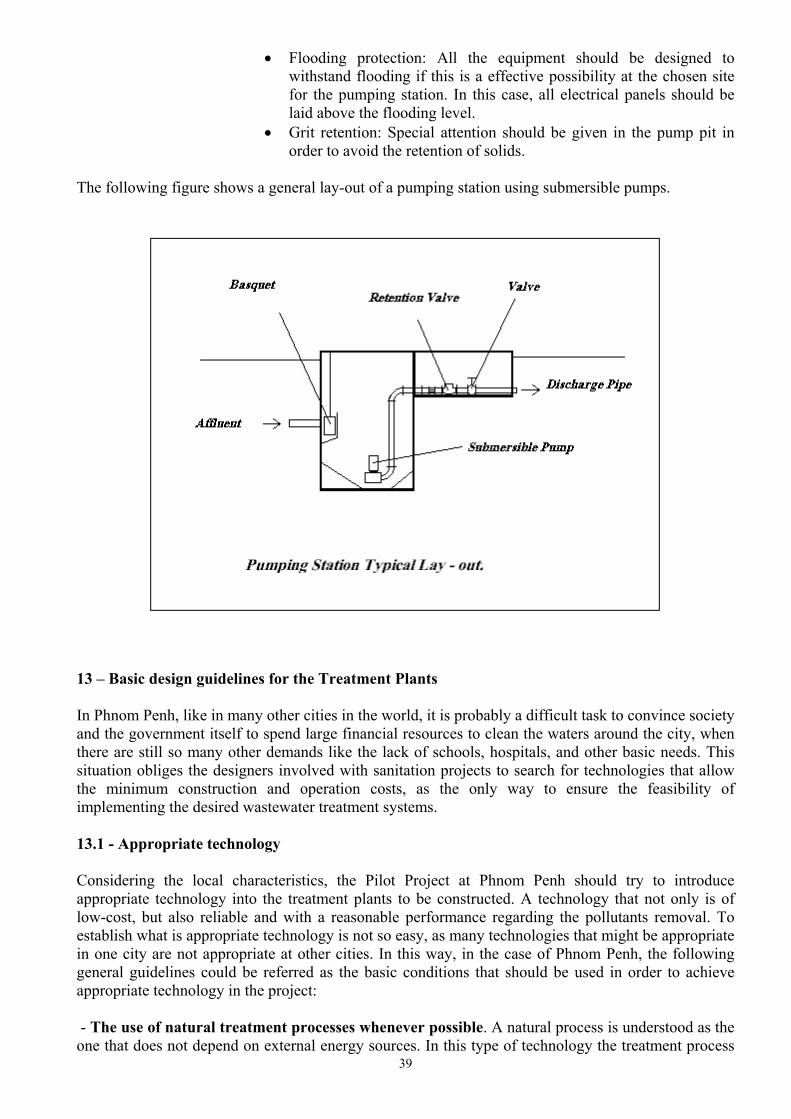
39
• Flooding protection: All the equipment should be designed to withstand flooding if this is a effective possibility at the chosen site for the pumping station. In this case, all electrical panels should be laid above the flooding level.
• Grit retention: Special attention should be given in the pump pit in order to avoid the retention of solids.
The following figure shows a general lay-out of a pumping station using submersible pumps.
13 – Basic design guidelines for the Treatment Plants In Phnom Penh, like in many other cities in the world, it is probably a difficult task to convince society and the government itself to spend large financial resources to clean the waters around the city, when there are still so many other demands like the lack of schools, hospitals, and other basic needs. This situation obliges the designers involved with sanitation projects to search for technologies that allow the minimum construction and operation costs, as the only way to ensure the feasibility of implementing the desired wastewater treatment systems. 13.1 - Appropriate technology
Considering the local characteristics, the Pilot Project at Phnom Penh should try to introduce appropriate technology into the treatment plants to be constructed. A technology that not only is of low-cost, but also reliable and with a reasonable performance regarding the pollutants removal. To establish what is appropriate technology is not so easy, as many technologies that might be appropriate in one city are not appropriate at other cities. In this way, in the case of Phnom Penh, the following general guidelines could be referred as the basic conditions that should be used in order to achieve appropriate technology in the project: - The use of natural treatment processes whenever possible. A natural process is understood as the one that does not depend on external energy sources. In this type of technology the treatment process
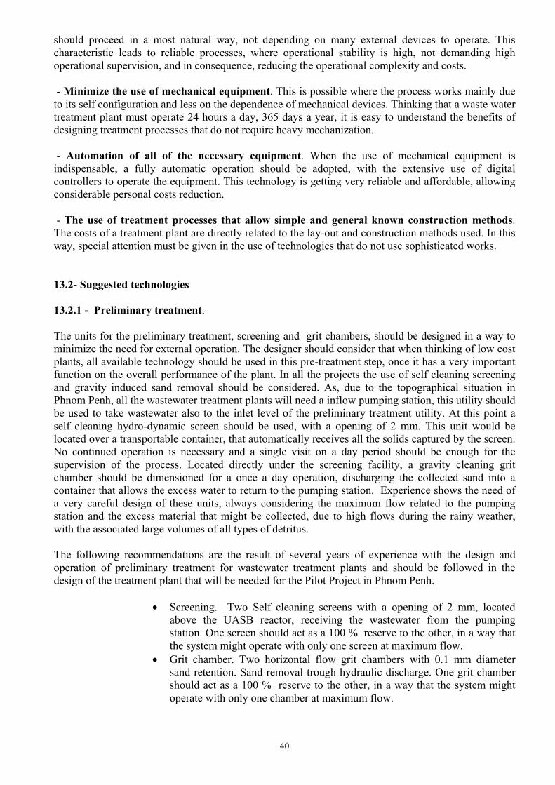
40
should proceed in a most natural way, not depending on many external devices to operate. This characteristic leads to reliable processes, where operational stability is high, not demanding high operational supervision, and in consequence, reducing the operational complexity and costs. - Minimize the use of mechanical equipment. This is possible where the process works mainly due to its self configuration and less on the dependence of mechanical devices. Thinking that a waste water treatment plant must operate 24 hours a day, 365 days a year, it is easy to understand the benefits of designing treatment processes that do not require heavy mechanization. - Automation of all of the necessary equipment. When the use of mechanical equipment is indispensable, a fully automatic operation should be adopted, with the extensive use of digital controllers to operate the equipment. This technology is getting very reliable and affordable, allowing considerable personal costs reduction. - The use of treatment processes that allow simple and general known construction methods. The costs of a treatment plant are directly related to the lay-out and construction methods used. In this way, special attention must be given in the use of technologies that do not use sophisticated works.
13.2- Suggested technologies 13.2.1 - Preliminary treatment. The units for the preliminary treatment, screening and grit chambers, should be designed in a way to minimize the need for external operation. The designer should consider that when thinking of low cost plants, all available technology should be used in this pre-treatment step, once it has a very important function on the overall performance of the plant. In all the projects the use of self cleaning screening and gravity induced sand removal should be considered. As, due to the topographical situation in Phnom Penh, all the wastewater treatment plants will need a inflow pumping station, this utility should be used to take wastewater also to the inlet level of the preliminary treatment utility. At this point a self cleaning hydro-dynamic screen should be used, with a opening of 2 mm. This unit would be located over a transportable container, that automatically receives all the solids captured by the screen. No continued operation is necessary and a single visit on a day period should be enough for the supervision of the process. Located directly under the screening facility, a gravity cleaning grit chamber should be dimensioned for a once a day operation, discharging the collected sand into a container that allows the excess water to return to the pumping station. Experience shows the need of a very careful design of these units, always considering the maximum flow related to the pumping station and the excess material that might be collected, due to high flows during the rainy weather, with the associated large volumes of all types of detritus. The following recommendations are the result of several years of experience with the design and operation of preliminary treatment for wastewater treatment plants and should be followed in the design of the treatment plant that will be needed for the Pilot Project in Phnom Penh.
• Screening. Two Self cleaning screens with a opening of 2 mm, located above the UASB reactor, receiving the wastewater from the pumping station. One screen should act as a 100 % reserve to the other, in a way that the system might operate with only one screen at maximum flow.
• Grit chamber. Two horizontal flow grit chambers with 0.1 mm diameter sand retention. Sand removal trough hydraulic discharge. One grit chamber should act as a 100 % reserve to the other, in a way that the system might operate with only one chamber at maximum flow.

41
13.2.2 - First treatment step. As Phnom Penh has no sufficient available area within its city limits to afford the construction of low cost, low operation oxidation ponds, the treatment to be chosen is to be compact and suitable within the city. For this objective the use of closed anaerobic upflow reactors – UASB, is recommended, as the first treatment step to be adopted in the city. This process allows a great reduction on the influent organic load, at a very low cost level. These reactors work on a almost operation free basis, presenting a highly stable effluent. A good operational performance could be expected throughout the year, due to the appropriate temperatures verified in Phnom Penh. The following recommendations are the result of several years of experience with the design and operation of UASB reactors for wastewater treatment plants and should be followed in the design of the treatment plants that will be needed for the Pilot Project in Phnom Penh.
• Retention time. The reactor should be designed for a 6 hour retention time at maximum flow.
• Reactor height. A 5 meter liquid height should be used for the reactor • Reactor shape. The reactor should be designed with a square or rectangular
shape, in order that all the superficial area is used as a settling tank • Settlers. Should have a minimum 1.20 m height with a 45 degrees slope. • Inlets: There should be a inlet point for each maximum of 4 m2 of the
reactors area. • Sludge production: A average 0.2 kg of sludge / kg of COD removed must
be considered for the reactor. • Sludge removal: A sludge removal point should be available for each 20 m2
of the reactors area. • Scum removal: The reactor should allow easy scum removal for every gas
collecting chamber. • Gas collectors: All of the Biogas that is generated in the process should be
collected and burned to avoid the propagation of bad odors. • Air filters: All the air that is in contact with the interior of the reactor and its
inlet and outlet devices should be extracted and filtered in a adequately designed biological air filter.
• Sludge handling: All the generated sludge must have a adequate destination.
The UASB should be designed according to the basic principles usually adopted for this type of reactor, see Souza (1987), or Lettinga (1995 ). The following figure shows a general lay-out of a UASB reactor, including the preliminary treatment.
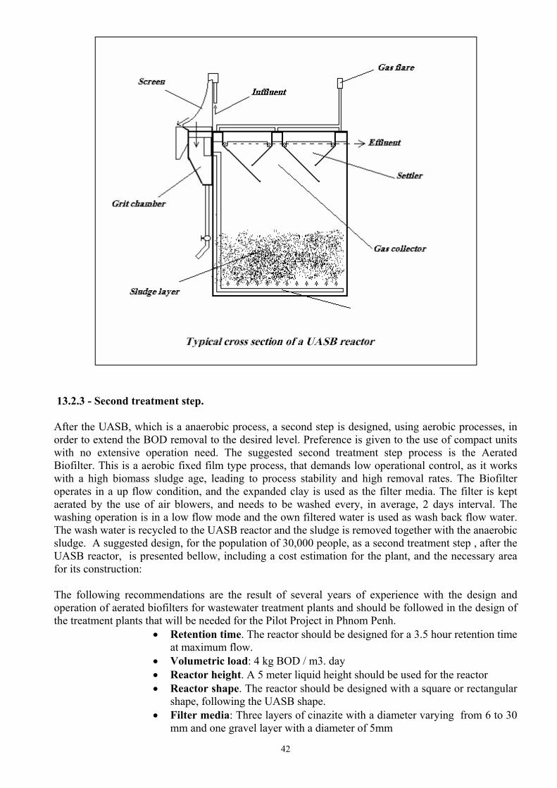
42
13.2.3 - Second treatment step. After the UASB, which is a anaerobic process, a second step is designed, using aerobic processes, in order to extend the BOD removal to the desired level. Preference is given to the use of compact units with no extensive operation need. The suggested second treatment step process is the Aerated Biofilter. This is a aerobic fixed film type process, that demands low operational control, as it works with a high biomass sludge age, leading to process stability and high removal rates. The Biofilter operates in a up flow condition, and the expanded clay is used as the filter media. The filter is kept aerated by the use of air blowers, and needs to be washed every, in average, 2 days interval. The washing operation is in a low flow mode and the own filtered water is used as wash back flow water. The wash water is recycled to the UASB reactor and the sludge is removed together with the anaerobic sludge. A suggested design, for the population of 30,000 people, as a second treatment step , after the UASB reactor, is presented bellow, including a cost estimation for the plant, and the necessary area for its construction: The following recommendations are the result of several years of experience with the design and operation of aerated biofilters for wastewater treatment plants and should be followed in the design of the treatment plants that will be needed for the Pilot Project in Phnom Penh.
• Retention time. The reactor should be designed for a 3.5 hour retention time at maximum flow.
• Volumetric load: 4 kg BOD / m3. day • Reactor height. A 5 meter liquid height should be used for the reactor • Reactor shape. The reactor should be designed with a square or rectangular
shape, following the UASB shape. • Filter media: Three layers of cinazite with a diameter varying from 6 to 30
mm and one gravel layer with a diameter of 5mm
43
• Air demand: 30 Nm3/kg.BOD. • Inlets: At the bottom of the reactor, with separate inlets for air and
wastewater. • Sludge production: A average 0.4 kg of sludge / kg of COD removed must
be considered for the reactor. • Sludge removal: Sludge is removed during the back wash of the filter and
should be discharged into the UASB. The Aerated Biofilter should be designed according to the basic principles usually adopted for this type of reactor, see Francis (1987). The following figure shows a general lay-out of a Aerated Biofilter:
13.2.4 – Treatment Plant lay-out. Adopting the recommendations above presented, the treatment plant should be a compact unit, with a very low operational demand. It is desired that the operation is done in a single daily visit, where all the supervision and operational actions can take place in one hour period. As the pilot project system will probably have several treatment and pumping facilities, it is foreseen that the same operational team will be responsible for all the units. The typical lay out for a treatment plant designed according to the presented recommendations can be seen in the following figure:

44
14 – Preliminary Commercial and financial implications of the Condominial System. Al the values below presented should be considered only as a preliminary approximation on the values that will be practiced by PPWSA, for the definitive cost for the system to be implanted are not available, and will only be determined after a detailed cost study, which will be done throughout the Pilot Project studies. 14.1 – Connection Fee As already mentioned, the connection fee should reflect the cost of the Condominial Branch, as this part of the system is supposed to be a private part of the system. The only additional costs that should be added to this cost are the financial and the administration costs for the service execution. The cost of the connection fee will depend on the politic established by the service supplier, regarding how the payment of the connection should be done by the user. It is quite common to establish a 12 parcels payment, after the system got in operation. As the system usually takes around 12 months to be implanted, in the average a 6 months period would be used as the period to start the payment. So the financial costs can be calculated according to this payment condition. Considering 12%/year interests rate and a 10 % for administration costs, the value of each parcel would represent 8 %, of the cost of the average condominial construction cost. In the case of Phnom Penh, considering a average condominial construction cost of around US$ 166 per Household, the financing and administration costs would represent US$41, what means that the Connection cost would be US$ 207, with a monthly payment of US$ 17 for each household. The resulting administration income for PPWSA would sum the amount US$ 8050,00 per month. These values were calculated for the preliminary data estimated for the Tomnop Tuk and Beng Trabek area.

45
Population: 30,024 Households: 5,004 Condominial branches estimated costs: US$ 832,000 Per Household Condominial branches estimated cost: US$ 166 Connection fee payment parcels: 12 Interest rate: 12% / year Administration fee: 10 % / year The consideration of the connection fee should also be evaluated together with the tariff evaluation, for the cost of the condominial system can be totally or partially financed trough the tariff, during the financing period, usually around 20 years. 14.2 – Tariff The tariff should basically cover two types of costs. The cost to keep the system running, and the cost for the recovery of the investment. The cost to keep the system running should include the operation, the maintenance and the administration costs of the system. Should also include the depreciation, to allow the future reposition of the worn out parts. The cost for the recovery of the investment should consider the time to pay the loan and the corresponding interest rate. The cost could also include a certain value for a profit to be gained. For the situation in Phnom Penh, the exact investment costs and operational costs will still have to be determined, and the following values should only be understood as a preliminary exercise, in order to have a first idea of the involved values to be used as tariff. 14.2.1 – Operational cost. For the operational cost of the system, the preliminary data estimated for the Tomnop Tuk and Beng Trabek area will be used, corresponding to the following characteristics:
• Condominial branches: 41,700 m • Public sewers: 7,600 m • Pumping Station 1: 15 HP • Pumping Station 2: 4 HP • Pumping Station 3: 6 HP • Treatment plant 1: 20,520 Inh. • Treatment plant 2: 9,500 Inh.
The operational costs estimated for this systems are as follows:
• Personnel US$ 6,945 / year • Equipment US$ 54,644 / year • Energy US$ 9,545 / year • Materials US$ 7,113 / year • Total US$ 78,247 /year

46
Considering a 10 % administration fee, the monthly tariff per household would sum the value of US$ 1.90 / connection . month. 14.2.2 – Investment recovery cost. For the cost recovery of the system, the preliminary data estimated for the Tomnop Tuk and Beng Trabek area will be used, considering the following financing conditions:
• Investment cost: US$ 3,000,000 • Interest rate: 12 % / year • Depreciation: 35 years • Profit: 10 % / year
With the above values, the following values can be calculated for the tariff: • Depreciation: US$ 85,724 / year • Cost recovery US$ 382.499 / year • Profit: US$ 330.504 / year • Operational costs US$ 78,247 / year These values represent a average tariff of US$ 14.60 / connection . Month.