Concrete subjected to projectile and fragment impacts...
14
International Journal of Impact Engineering 32 (2006) 1828–1841 Concrete subjected to projectile and fragment impacts: Modelling of crack softening and strain rate dependency in tension Joosef Leppa¨nen Department of Structural Engineering and Mechanics, Concrete Structures, Chalmers University of Technology, SE-412 96 Go¨teborg, Sweden Received 6 September 2004; received in revised form 4 March 2005; accepted 13 June 2005 Available online 8 September 2005 Abstract This paper deals with modelling of plain concrete in tension. The aim is to improve the accuracy of the numerical analyses for projectile and fragment impacts on concrete. A bi-linear crack softening law and a strain rate-dependent law are implemented in the hydrocode AUTODYN. Parametric studies are made, and numerical analyses are compared with experiments conducted and with experiments found in the literature. The depth of penetration is mainly dependent on the compressive strength of the concrete. However, to correctly model spalling, cracking and scabbing in concrete, the tensile strength, fracture energy, and strain rate in tension are very important. It is shown that the accuracy of the results in the numerical analyses of concrete subjected to projectile and fragment impacts was improved, when using a bi- linear softening law and the modified strain rate dependency for tension. r 2005 Elsevier Ltd. All rights reserved. Keywords: Concrete; Projectile and fragment impacts; Numerical modelling; Crack softening; Strain rate in tension 1. Introduction High-velocity impact on concrete structures has been a subject of numerical analyses in recent decades. The main focus has been on modelling the compressive behaviour of concrete. ARTICLE IN PRESS www.elsevier.com/locate/ijimpeng 0734-743X/$ - see front matter r 2005 Elsevier Ltd. All rights reserved. doi:10.1016/j.ijimpeng.2005.06.005 Fax: +46(0)31 772 2260. E-mail address: [email protected].
Transcript of Concrete subjected to projectile and fragment impacts...

ARTICLE IN PRESS
International Journal of Impact Engineering 32 (2006) 1828–1841
0734-743X/$ -
doi:10.1016/j.
�Fax: +46(
E-mail add
www.elsevier.com/locate/ijimpeng
Concrete subjected to projectile and fragment impacts:Modelling of crack softening and strain rate
dependency in tension
Joosef Leppanen�
Department of Structural Engineering and Mechanics, Concrete Structures, Chalmers University of Technology,
SE-412 96 Goteborg, Sweden
Received 6 September 2004; received in revised form 4 March 2005; accepted 13 June 2005
Available online 8 September 2005
Abstract
This paper deals with modelling of plain concrete in tension. The aim is to improve the accuracy of thenumerical analyses for projectile and fragment impacts on concrete. A bi-linear crack softening law and astrain rate-dependent law are implemented in the hydrocode AUTODYN. Parametric studies are made,and numerical analyses are compared with experiments conducted and with experiments found in theliterature. The depth of penetration is mainly dependent on the compressive strength of the concrete.However, to correctly model spalling, cracking and scabbing in concrete, the tensile strength, fractureenergy, and strain rate in tension are very important. It is shown that the accuracy of the results in thenumerical analyses of concrete subjected to projectile and fragment impacts was improved, when using a bi-linear softening law and the modified strain rate dependency for tension.r 2005 Elsevier Ltd. All rights reserved.
Keywords: Concrete; Projectile and fragment impacts; Numerical modelling; Crack softening; Strain rate in tension
1. Introduction
High-velocity impact on concrete structures has been a subject of numerical analyses inrecent decades. The main focus has been on modelling the compressive behaviour of concrete.
see front matter r 2005 Elsevier Ltd. All rights reserved.
ijimpeng.2005.06.005
0)31 772 2260.
ress: [email protected].
ARTICLE IN PRESS
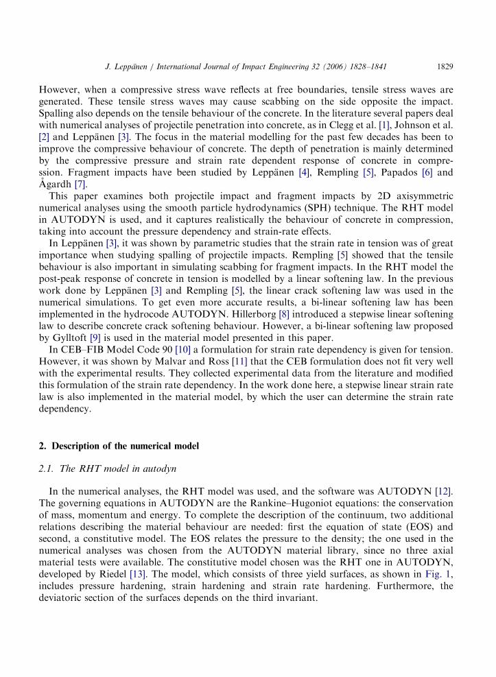
J. Leppanen / International Journal of Impact Engineering 32 (2006) 1828–1841 1829
However, when a compressive stress wave reflects at free boundaries, tensile stress waves aregenerated. These tensile stress waves may cause scabbing on the side opposite the impact.Spalling also depends on the tensile behaviour of the concrete. In the literature several papers dealwith numerical analyses of projectile penetration into concrete, as in Clegg et al. [1], Johnson et al.[2] and Leppanen [3]. The focus in the material modelling for the past few decades has been toimprove the compressive behaviour of concrete. The depth of penetration is mainly determinedby the compressive pressure and strain rate dependent response of concrete in compre-ssion. Fragment impacts have been studied by Leppanen [4], Rempling [5], Papados [6] andAgardh [7].This paper examines both projectile impact and fragment impacts by 2D axisymmetric
numerical analyses using the smooth particle hydrodynamics (SPH) technique. The RHT modelin AUTODYN is used, and it captures realistically the behaviour of concrete in compression,taking into account the pressure dependency and strain-rate effects.In Leppanen [3], it was shown by parametric studies that the strain rate in tension was of great
importance when studying spalling of projectile impacts. Rempling [5] showed that the tensilebehaviour is also important in simulating scabbing for fragment impacts. In the RHT model thepost-peak response of concrete in tension is modelled by a linear softening law. In the previouswork done by Leppanen [3] and Rempling [5], the linear crack softening law was used in thenumerical simulations. To get even more accurate results, a bi-linear softening law has beenimplemented in the hydrocode AUTODYN. Hillerborg [8] introduced a stepwise linear softeninglaw to describe concrete crack softening behaviour. However, a bi-linear softening law proposedby Gylltoft [9] is used in the material model presented in this paper.In CEB–FIB Model Code 90 [10] a formulation for strain rate dependency is given for tension.
However, it was shown by Malvar and Ross [11] that the CEB formulation does not fit very wellwith the experimental results. They collected experimental data from the literature and modifiedthis formulation of the strain rate dependency. In the work done here, a stepwise linear strain ratelaw is also implemented in the material model, by which the user can determine the strain ratedependency.
2. Description of the numerical model
2.1. The RHT model in autodyn
In the numerical analyses, the RHT model was used, and the software was AUTODYN [12].The governing equations in AUTODYN are the Rankine–Hugoniot equations: the conservationof mass, momentum and energy. To complete the description of the continuum, two additionalrelations describing the material behaviour are needed: first the equation of state (EOS) andsecond, a constitutive model. The EOS relates the pressure to the density; the one used in thenumerical analyses was chosen from the AUTODYN material library, since no three axialmaterial tests were available. The constitutive model chosen was the RHT one in AUTODYN,developed by Riedel [13]. The model, which consists of three yield surfaces, as shown in Fig. 1,includes pressure hardening, strain hardening and strain rate hardening. Furthermore, thedeviatoric section of the surfaces depends on the third invariant.

ARTICLE IN PRESS
Residual Strength
Elastic Limit Surface
Failure Surface
Yield strength, Y
Pressure, p
Fig. 1. The RHT constitutive model used for concrete [13].
ft wu = 4GF/ftε
ft /3 GF
wu/6 wu w
k1
k2
� �
Fig. 2. Bi-linear uniaxial stress-crack opening relationship; based on Gylltoft [9].
J. Leppanen / International Journal of Impact Engineering 32 (2006) 1828–18411830
2.2. Modified crack softening law
In AUTODYN, a linear softening law is included to model the post-failure response of concretetension. However, concrete is a very brittle material and the strength decreases rapidly after thefailure initiation; therefore a modified crack softening law is implemented in the numerical model.Hillerborg [8] originally presented a stepwise linear crack softening law. After Hillerborgpublished his work, there were several other proposals for the crack softening, for exampleGylltoft [9] and Hillerborg [14]. The softening law chosen for this paper, proposed by [9] is basedon the stress-crack opening relationship. To calculate the crack width wu (when the stress hasfallen to zero and a real crack has formed) the fracture energy, GF, and the tensile strength, ft, ofconcrete are used, as shown in Fig. 2. However, the AUTODYN model follows smeared crackapproach, and consequently a stress–strain relation is used; the maximum cracking strain iscalculated from the maximum crack opening as
�u ¼wu
l¼
4GF
f tl. (1)
The crack width is smeared out over a distance, l. In two-dimensional models for un-reinforcedconcrete, this distance is normally approximated by the square root of the area of an element, seeJohansson [15]. For three-dimensional models, the length is taken to be the third root of thevolume of the element. The two slopes, k1 and k2 in Fig. 2, for the bi-linear crack softening law

ARTICLE IN PRESS
J. Leppanen / International Journal of Impact Engineering 32 (2006) 1828–1841 1831
can be described by using Eq. (1)
k1 ¼f 2t
GF; k2 ¼
f 2t
10GF. (2)
In AUTODYN the bi-linear crack softening law was implemented with subroutines. Thepredefined slope for linear crack softening was used. The linear softening slope is defined as
k ¼f 2t
2GF. (3)
When the tensile failure stress has been reached, the slopes, k1 and k2, can be described by usingthe predefined slope in AUTODYN
k1 ¼ 2k for �p1
6�u, (4)
k2 ¼2
10k for �4
1
6�u, (5)
where e is the cracking strain and eu is the ultimate cracking strain (when the stress has fallen tozero).
2.3. Modified strain rate law for concrete in tension
Concrete is very strain rate sensitive. In the CEB–FIB Model Code [10], there is a relationship forDIF (dynamic increase factor) for tension at varying strain rates. The DIF in the code is a designvalue, which means the increase in strength is given at a higher strain rate than in the experiments.Results presented in [11] show that the sudden increase in DIF for concrete in tension occurs at astrain rate of approximately 1 s�1. Fig. 3 shows a comparison of a proposed model [11] and the code[10]. The model fits the experimental data, as shown in the figure. The equations are [11],
f ct
f cts
¼_�
_�s
� �d
for _�p1 s�1, (6)
f ct
f cts
¼ b_�
_�s
� �1=3
for _�41 s�1, (7)
where fct is dynamic tensile strength at _�, fcts is static tensile strength at _�s, fct/ fcts is the DIF(dynamic increase factor), _� is the strain rate in the range of 10�6 to 160 s�1,
_�s ¼ 10�6 s�1 ðstatic strain rateÞ,
log b ¼ 6d� 2;
d ¼1
1þ ð8f 0c=f 0coÞ
f 0co ¼ 10MPa:
In the RHT model the DIF for tension is determined by the parameter d, see [12]. Fig. 4 showsthe DIF for two values of d. As seen in the figure, this parameter cannot be chosen in a way that fits

ARTICLE IN PRESS
0
1
2
3
4
5
6
7
8
Strain rate [s-1]
CEB 30 MPa ModifiedCEB 30 MPaCEB 70 MPa ModifiedCEB 70 MPaCowell 63 MPa Cowell 38 MPaCowell 32 MPa Hatano 23 MPaTakeda/Tachikawa Mellinger/Birkimer 36 MPaBirkimer 47 MPa McVay 35 MPaRoss split tension Ross direct tensionRoss mixes E-J Kormeling et alJohn et al. 53 MPa Antoun 57 MPa
DIF
(D
ynam
ic in
crea
se f
acto
r)
10-6 10-5 10-4 10-3 10-2 10-1 100 101 102 103
Fig. 3. Strain rate dependency for concrete in tension. Comparison of experimental data: the proposed model [11]
(Modified CEB), and recommendations according to [10] (CEB); based on Malvar and Ross [11].
0
1
2
3
4
5
6
7
8
Strain rate [s-1]
Mod ified RHT
RHT = 0.070
RHT = 0.036
DIF
(D
ynam
ic in
crea
se f
acto
r)
10-6 10-5 10-4 10-3 10-2 10-1 100 101 102 103
�
�
Fig. 4. The strain rate dependency for concrete in tension with the RHT model and the modified RHT model. d is a
strain rate parameter in the RHT model, see [12,13].
J. Leppanen / International Journal of Impact Engineering 32 (2006) 1828–18411832
the experimental data in Fig. 3. For this reason a strain rate law was implemented in the RHTmodel. In the RHT model the strain rate law was implemented as a stepwise linear by usingsubroutines in AUTODYN, for which the DIF relationship can be chosen by the user; in the figurethe DIF chosen according to [11] is shown.
3. Parametric studies
Parametric studies were conducted with the modified RHT model to study the effects of thesoftening slope, the strain rate law, variations of the fracture energy and the tensile strength. Theimpact of a fragment on a disc-shaped concrete target with a diameter of 1m and thickness of

ARTICLE IN PRESS
J. Leppanen / International Journal of Impact Engineering 32 (2006) 1828–1841 1833
140mm at a velocity of 1163m/s was examined. The values are taken from an experimentanalysed in Section 4 (example 3), and the material parameters used in the study are from thesame example. The fragment and the concrete target were modelled by 2D axisymmetric model,and the fragment strikes the centre of the concrete disc.When using a bi-linear softening slope, there was a minor difference in the damage in
comparison with a linear softening slope, as shown in Fig. 5. In the analyses, bi-linear softeningslope and the linear softening slope had the same fracture energy. The modified strain rate law wasused. The depth of penetration was approximately the same for both analyses. However, due tothe more brittle material behaviour in the bi-linear analyses, there was slightly more damage: thediameter of scabbing increased only by 2.0% and there were more cracks. The results indicate thatthe shape of the softening curve is less important for scabbing in concrete.To study the effect of the strain rate law that was implemented in the RHT model, a
comparison of the proposed model [11] and the code [10] was made. Results in Fig. 6 show thatthe cracking is reduced, and the diameter of scabbing is reduced by 11% when using the firstmodel [11]. This is due to the increase in dynamic tensile strength.To study the effect of the tensile strength three values of the static tensile strength, 0.05, 0.071
and 0.1, of the mean value of the compressive strength were used. The results of the analyses showthat the crack width increases when using lower static tensile strength, Fig. 7. Furthermore, forthe highest tensile strength, the crack has not fully extended to the side opposite the impact.To find the effect of fracture energy, it was varied between 85 and 205Nm/m2, as shown in
Fig. 8. It was found that the fracture energy has a minor effect on the depth of penetration andspalling. However, by increasing the fracture energy, scabbing and cracking were highly reduced.
4. Comparison of the numerical model and experimental results
To ensure that a numerical model can predict the depth of penetration, spalling and scabbing,results from several experiments with varying mass and impact velocities must be reproduced.
Fig. 5. Comparison of the effects of two crack-softening slopes. Left: Linear; Right: Bi-linear.

ARTICLE IN PRESS
Fig. 7. Comparison of the effects of three static tensile strengths; fctm ¼ mean tensile strength and fcm ¼ mean
compressive strength.
Fig. 6. Comparison of the effects of the strain rate law. Left: CEB–FIB [10]; Right: Malvar and Ross [11].
J. Leppanen / International Journal of Impact Engineering 32 (2006) 1828–18411834
Here three series of experiments were analysed with the modified RHT model. The input data aregiven in Table 1, for more details of the model, see [12] and [13]. The first example is fromLeppanen [16], the second from Hansson [17] and the third from Erkander and Pettersson [18].In the first series [16] the experiments were conducted by shooting single fragments against
concrete blocks. The dimensions of the blocks were 750� 375� 500mm, and the fragments werespherical with a radius of 4mm. The concrete had a cylinder strength of 31.2MPa, tensile strengthof 2.84MPa, fracture energy of 84Nm/m2 and the maximum aggregate size of 8mm. A total ofeight shots were made with impact velocities varying from 1754 to 2000m/s. Two or three shotswere made for each block. The depth of penetration for the eight shots varied between 52 and57mm, and the crater width varied from 74mm up to 93mm. Although multiple fragments wereshot against the concrete blocks, the results discussed in this paper are limited to single-fragment

ARTICLE IN PRESS
Fig. 8. Effects of variation in the level of fracture energy.
J. Leppanen / International Journal of Impact Engineering 32 (2006) 1828–1841 1835
impacts. Information about the multiple fragment impacts may be found elsewhere [16]. Acomparison of experiments and an analysis made with the material model, described in Section 2,are shown in Fig. 9; the block is cut in half, and a cross section is shown as well as the plane viewof the fragment impacts. A magnification of the area of fragment impact is compared with anumerical analysis. For this shot, the impact velocity was recorded as 1879m/s; the depth ofpenetration was 54mm and the maximum crater diameter was 93mm. In the numerical analysisthe depth of penetration was 52mm and the maximum crater diameter was in good agreement.However, the tunnelling was not captured. For comparison, the true depth of penetration and thetrue crater diameter is also shown in the numerical result, see Fig. 9.The second series analysed for experiments conducted by Hansson [17], in which a projectile
impacts a concrete cylinder. The ogive-nose steel projectile used had a mass of 6.28 kg, length of225mm, diameter of 75mm, density of 7 830 kg/m3, bulk modulus of 159GPa, shear modulus of81.8GPa, and yield stress of 792MPa; the impact velocity was 485m/s. The target was a concretecylinder, cast in a steel culvert, with a diameter of 1.6m and a length of 2m. The concrete cubestrength was approximately 40MPa (tested on a 150mm cube). The tensile strength and fractureenergy were calculated according to CEB; tensile strength was 2.64MPa and fracture energy was100Nm/m2. Two shots were fired at the same impact velocity, the first with support and the

ARTICLE IN PRESS
Table 1
Input data in Autodyn for modelling concrete
Parameter Value Comments
Shear modulus (kPa) G a
Compressive strength fc (MPa) fca
Tensile strength ft/fc 0.071–0.091 a
Shear strength fs/fc 0.18 (default)
Failure surface parameter A 2 b
Failure surface parameter N 0.7 b
Tens./compr.mMeridian ratio 0.6805 (default)
Brittle to ductile transition 0.0105 (default)
G(elas.)/G(elas-plas.) 2 (default)
Elastic strength/ft 0.7 (default)
Elastic strength/fc 0.53 (default)
Use cap on elastic surface Yes (default)
Residual strength const. B 1.8 b,c and d
Residual strength exp. M 0.7 b
Comp. strain rate exp. a 0.032 (default)
Tens. strain rate exp. d User-subroutine d
Max. fracture strength ratio 1� 1020 (default)
Damage constant D1 0.04 (default)
Min. strain to failure 0.01 (default)
Residual shear modulus frac. 0.13 (default)
Tensile failure model User-subroutine d
Erosion strain/instantaneous geometric strain (only for Lagrange) 1.5 c
aMaterial tests or calculated according to the [10].bCalculated with a model proposed by Attard and Setunge (1996).cCalibrated by parametric studies.dRHT model without user-subroutine, B ¼ 1:5 and d ¼ 0:025 were used. The tensile failure model hydro was used.
J. Leppanen / International Journal of Impact Engineering 32 (2006) 1828–18411836
second without support at the opposite side of the target. The depth of penetration was hardlyinfluenced by the support: the difference was only 5mm. For the shot without support the depthof penetration was 655mm; for the second shot the depth of penetration was 660mm. The craterdiameter in the experiment was approximately 800mm. In Fig. 10, a result from a numericalanalysis is shown for a projectile striking a target without support on the opposite side. The depthof penetration was 643mm and the maximum crater diameter was 780mm. Analysis with theRHT model was also conducted, the result is shown in the same figure. Detailed input for theanalysis is published in [3].In the third series tested with the model, experiments where scabbing occurred were analysed.
Scabbing is caused by the reflected tensile stress wave; due to this it is important that thetensile behaviour be accurately described. In the experiments, which were conducted [18],single fragments were shot against concrete walls. The dimensions of the walls were1000� 1000mm with a thickness of 140mm, and the fragments were spherical with a radiusof 10.3mm. The concrete has an average cube strength of 68.9MPa (tested on 150� 150mmcubes). The tensile strength and fracture energy was calculated according to CEB; tensile strength

ARTICLE IN PRESS
Fig. 9. Comparison of numerical result and experimental result. Experiments conducted by Leppanen [16].
J. Leppanen / International Journal of Impact Engineering 32 (2006) 1828–1841 1837
was 4.14MPa and fracture energy was 145Nm/m2. The results compared had impact velocitiesof 1024m/s, 1163m/s and 1238m/s. The first shot analysed had a velocity of 1024m/s: the depthof penetration was 50mm, spalling diameter was 270mm and the diameter of scabbing was380mm. The second shot analysed had a velocity of 1163m/s: the depth of penetration was66mm, spalling diameter was 240mm and the diameter of scabbing was 310mm. Finally, thethird shot analysed had a velocity of 1283m/s: the depth of penetration was 50mm, spallingdiameter was 230mm and the diameter of scabbing was 360mm. Numerical analyses with themodified RHT model are shown in Fig. 11, as well as results with the RHT model. The spallingwas not accurately captured for the fragment impacts with velocities of 1024m/s and 1163m/s.However, the scabbing was in good agreement with the experimental results. For the shot with avelocity of 1283m/s, both the spalling and the scabbing diameter were in good agreement with theexperimental result.To sum up the third series, the deviation, in scabbing diameter, between experiments and
numerical analyses with the RHT model was between 6 and 28%, while with the modified RHTmodel the deviation was only between 2 and 10%.

ARTICLE IN PRESS
Fig. 10. Computed cratering and the depth of penetration of a projectile impact on a concrete cylinder. The
arrows show the crater diameter and depth reported by Hansson [17]. Above: RHT model; Below: modified RHT
model.
J. Leppanen / International Journal of Impact Engineering 32 (2006) 1828–18411838
5. Discussion
In the parametric study, by increasing the fracture energy, as a consequence the maximumcracking strain increases and the consumed energy increases; and as a result the scabbing diameterdecreases. However, the shape of the softening curve had a minor influence on the results, theconsumed energy was approximately the same.During the fragment penetration the strain rate varies in the concrete, and therefore it is
important to have a model that realistically describes accurate tensile failure stress. For anexample, for the proposed model [11] the tensile failure stress becomes more than two times higherthan for the code [10] for the strain rate 10 s�1. Furthermore, the failure mode is influenced on thestrain rate in tension, which can be seen Fig. 11, for the modified RHT model the crackpropagation do not start at same location as for the RHT model.To improve the accuracy in the simulations even further, more research must be done.
In the simulations the tunnelling was not captured in one of the simulations, see Fig. 9;and the spalling was not accurate for the fragment impacts velocities of 1024 and1163m/s as shown in Fig. 11. However, to incorporate the tensile behaviour accuratelyis a right step in improving the simulation technique for projectile and fragment impacts onconcrete.

ARTICLE IN PRESS
Fig. 11. Numerical analyses of fragment penetration, concrete spalling and scabbing. Dotted lines show craters
reported by Erkander and Pettersson [18]. Above: RHT model; Below: modified RHT model.
J. Leppanen / International Journal of Impact Engineering 32 (2006) 1828–1841 1839
6. Summary and conclusions
For projectile and fragment impacts, the velocity and the concrete strength, which depend onthe pressure and the strain rate in compression, mainly influence the depth of penetration.However, cracking and scabbing are mainly influenced by the tensile strength, fracture energy andthe strain rate in tension. For fragment impacts, spalling is caused by the direct impact due tocrushing of the concrete. For projectile impacts, the spalling crater size also depends on the strainrate in tension as shown.Parametric studies of fragment impacts were conducted. The crack width and scabbing increase
with decreasing static tensile strength. By increasing the fracture energy, the cracking andscabbing were greatly reduced. However, this increase had a minor effect on the depth ofpenetration and spalling. Using a bi-linear softening law for tension increases the damage and thediameter of scabbing only slightly more than a linear one. Moreover, the scabbing was greatlyinfluenced by the strain rate law. By using a DIF in tension, where the sudden increase in strengthoccurs at lower strain rates, the scabbing is decreased.

ARTICLE IN PRESS
J. Leppanen / International Journal of Impact Engineering 32 (2006) 1828–18411840
The strain rate in tension for concrete depends on the projectile or fragment mass and theimpact velocity. Thus, to predict the depth of penetration, spalling and scabbing, a material modelthat can accurately describe the DIF for tension must be used. To increase the accuracy ofnumerical analyses for both projectile and fragment impacts, a bi-linear crack softening law and astrain rate law were implemented in the RHT model in the software AUTODYN. It is also shownthat the implementation gives results that are in good agreement with experimental results for thespalling, cracking and scabbing of plain concrete subjected to fragment and projectile impacts.
Acknowledgements
For the research presented in this paper financial support was obtained from the SwedishRescue Services Agency. The author would like to thank his supervisor, the Head of theDepartment of Structural Engineering and Mechanics, Professor Kent Gylltoft, and members ofthe reference group for the project, ‘‘Dynamic behaviour of concrete structures subjected toblast and fragment impacts’’: Bjorn Ekengren, M.Sc., at the Swedish Rescue Services Agency,Mario Plos, Ph.D., at Chalmers University of Technology, and Morgan Johansson, Ph.D., atReinertsen AB.
References
[1] Clegg RA, Sheridan J, Hayhurst CJ, Francis NJ. The application of SPH techniques in AUTODYN-2D to kinetic
energy penetrator impacts on multi-layered soil and concrete targets. Eighth International Symposium on
Interaction of the Effects of Munitions with Structures, 22–25 April 1997, VA, USA. 9pp.
[2] Johnson GR, Stryk RA, Beissel SR, Holmquist TJ. An algorithm to automatically convert distorted finite elements
into meshless particles during dynamic deformation. Int J Impact Engng 2002;27(10):997–1013.
[3] Leppanen J. Dynamic Behaviour of concrete structures subjected to blast and fragment impacts. Licentiate Thesis,
Department of Structural Engineering, Concrete Structures, Goteborg, Sweden: Chalmers University of
Technology, 2002. 71pp.
[4] Leppanen J. Experiments and numerical analyses of blast and fragment impacts on concrete. Int J Impact Engng
2005;31(7):843–60.
[5] Rempling R. Concrete wall subjected to fragment impacts: Numerical analyses of perforation and scabbing.
Department of Structural Engineering and Mechanics, Concrete Structures, Master0s thesis nr. 04:1, Goteborg,
Sweden: Chalmers University of Technology, 2004. 55pp.
[6] Papados PP. A reinforced concrete structure under impact: Response to high rate loads. In: Jones N, Brebbia CA,
editors. Sixth International Conference on Structures Under Shock and Impact VI. Southampton: WIT Press;
2000. p. 501–10.
[7] Agardh L, Laine L. 3D FE-simulation of high-velocity fragment perforation of reinforced concrete slabs. Int J
Impact Engng 1999;22(9):911–22.
[8] Hillerborg A. Analysis of fracture by means of the fictitious crack model, particularly for fibre reinforced concrete.
The Int J Cement Composites 1980;2(4):177–84.
[9] Gylltoft K. Fracture mechanics models for fatigue in concrete structures. Doctoral Thesis, Division of Structural
Engineering, Lulea University of Technology, Lulea, Sweden, 1983. 210pp.
[10] CEB–FIB Model Code 1990. Design Code. Lausanne, Switzerland: Thomas Telford; 1993 437pp.
[11] Malvar LJ, Ross CA. Review of strain rate effects for concrete in tension. ACI Materials J 1998;95(6):735–9.
[12] AUTODYN Manuals. Version 5, Concord, CA, USA: Century Dynamics, Inc. 2004.

ARTICLE IN PRESS
J. Leppanen / International Journal of Impact Engineering 32 (2006) 1828–1841 1841
[13] Riedel W. Beton unter dynamischen Lasten Meso- und makromechanische Modelle und ihre Parameter (in
German). Doctoral Thesis, der Bundeswehr Munchen, Freiburg, Germany: Institut Kurzzeitdynamik, Ernst-
Mach-Institut, 2000. 210pp.
[14] Hillerborg A. The theoretical basis of a method to determine the fracture energy GF of concrete. Rilem Technical
Committees 1985;18(106):291–6.
[15] Johansson M. Structural behaviour in concrete frame corners of civil defence shelters, non-linear finite element
analyses and experiments. Doctoral Thesis, Department of Structural Engineering, Concrete Structures, Goteborg,
Sweden: Chalmers University of Technology, 2000. 204pp.
[16] Leppanen J. Splitterbelastad betong, Experiment och numeriska analyser (In Swedish). Fragment impacts on
concrete: Experiments and numerical analyses. Department of Structural Engineering and Mechanics, Concrete
Structures, Report nr. 03:6, Goteborg, Sweden: Chalmers University of Technology, 2003. 74pp.
[17] Hansson H. Numerical simulation of concrete penetration. FOA report 98-00816-311-SE, Defence research
establisment, Tumba, Sweden, 1998, 17pp.
[18] Erkander A, Pettersson L. Betong som splitterskydd: Skjutforsok pa plattor av olika betongmaterial (in Swedish).
(Concrete as a protective barrier against fragment impacts: Fragment impacts on plates made of different
concretes. FOA report C 20574-D6(D4), Stockholm, Sweden: Swedish Defence Research Agency, 1985. 66pp.