AIAA 2001-3433 Paper - Unmanned Air Ground Vehicle...
17
AIAA 2001-3433 Unmanned Air Ground Vehicle M. Janetka, L. Filz, N. Smith, and R.A. Frederick, Jr. University of Alabama in Huntsville Huntsville, AL 35899 37 th AIAA/ASME/SAE/ASEE Joint Propulsion Conference and Exhibit July 8-11, 2001, Salt Lake City, Utah For permission to copy or republish, contact the American Institute of Aeronautics and Astronautics, 1801 Alexander Bell Drive, Suite 500, Reston, VA 20191-4344
Transcript of AIAA 2001-3433 Paper - Unmanned Air Ground Vehicle...

AIAA 2001-3433
Unmanned Air Ground Vehicle
M. Janetka, L. Filz, N. Smith, and R.A. Frederick, Jr.University of Alabama in HuntsvilleHuntsville, AL 35899
37th AIAA/ASME/SAE/ASEEJoint Propulsion Conference and Exhibit
July 8-11, 2001, Salt Lake City, Utah
For permission to copy or republish, contact the American Institute of Aeronautics and Astronautics,1801 Alexander Bell Drive, Suite 500, Reston, VA 20191-4344
AIAA 2001-3433
American Institute of Aeronautics and Astronautics1
UNMANNED AIR GROUND VEHICLE
Melanie Janetka,* Laura Filz,* Nathan W. Smith*, and Robert Frederick, Jr.?
Department of Mechanical and Aerospace EngineeringUniversity of Alabama at Huntsville,
Huntsville, Alabama 35899
* Student Member, AIAA? Associate Professor, Department of Mechanical and Aerospace Engineering, Associate FellowCopyright 2001 by Robert A. Frederick, Jr. Published by the American Institute of Aeronautics and Astronautics, Inc. with permission
AbstractEarly strike forces of the future military areenvisioned as being lightly armored to enable a rapiddeployment. The increased vulnerability andoperational tempo of lightly armored forces evokesthe need for beyond-line-of-sight reconnaissancecapability under the control of the troops on theground. The objective of this work is to exploresystem level concepts that can provide this capabilityusing a combined unmanned air/ground vehicle(UAGV). The study included requirement definition,concept syntheses, and the evaluation of three finalconfigurations to meet the mission requirements.Three integrated product teams worked in a designcompetition. Engineering students from theUniversity of Alabama in Huntsville and ESTACAparticipated on the teams. The final conceptsincluded a ducted fans/pulse detonation enginevehicle, a flapping wings concept powered by electricmotors, and an ion dive idea powered by advancedfuel cells. An overview of each design is given, aswell as a more in depth look at the top rankedproposal.
NOMENCLATURE
BLOS Beyond Line of SightCNN Cable News NetworkFLOT Forward Line of TroopsIPT Integrated Product TeamLOS Line of SightOp Tempo Operational TempoPDE Pulse Detonation EngineRSTA Reconnaissance Surveillance and
Target AcquisitionUAGV Unmanned Air/Ground
VehicleUAH The University of Alabama in
HuntsvilleVROC Vertical Rate of Climb
IntroductionUAH IPT Project Background
In high-technology business, companies are usingmulti-disciplinary teams to decrease product costsand reduce time to market. This approach demandsthat specialist from diverse backgrounds learn how towork interactively under a set of system-levelrequirements. Top companies must be able to puttogether products in conjunction with domestic andinternational business partners using advancedtechnologies in a dynamic political/economicenvironment.
The University of Alabama in Huntsville (UAH)has established an Integrated Product Team (IPT)project to better introduce students to this teamworkenvironment. The IPT project uses industrialmentors1,2 to guide teams of engineering,3 business,4
and liberal arts5 students in a competitive designproject.6 Past projects have included a hybrid rocketsub-orbital vehicle,7 a tactical missile,8 a maglevtrain, a rocket-launched glider, two advancedrotorcraft projects,9 and a crew transport/recoveryvehicle for the International Space Station.10 Detailsof these projects can also be found at thewww.eb.uah.edu/ipt web page.
UAGV Project IntroductionThe IPT 2001 project was to design an UnmannedAir/Ground Vehicle (UAGV). The project is aparallel research/education effort sponsored by theU.S. Army Aviation and Missile Command. Threeinternational teams of undergraduate studentscompeted to present the best configuration of aUAGV. The teams consisted of mechanical,aerospace, electrical, computer and industrialengineers from the University of Alabama inHuntsville. They also included engineering studentsfrom ESTACA, a college in France. Each team had15 members.

AIAA 2001-3433
American Institute of Aeronautics and Astronautics2
The IPT project begins with a series of backgroundlectures and meetings among the team leaders andcustomer representatives to develop a writtenConcept Description Document that details therequirements for the system. The next semester threeIPTs are formed. Thirty four seniors from the UAHDepartment of Mechanical and AerospaceEngineering, twelve fourth-year students fromESTACA an engineering college in France, and fourstudents from the UAH Department of Electrical andComputer Engineering were distributed among thethree teams.
In Phase 1 of the project all three teams workedtogether to configure a baseline vehicle thatattempted to fulfill the project requirements usingexisting technology. During this phase an assessmentof existing vehicles was also made to see how manyof the requirements they could meet. This establishesthe deficiencies of current technologies and gives thementors a chance to interact with the students tointegrate components of the design process. At theend of this phase, a Review Team consisting ofgovernment and industry professionals is briefed.The students present the baseline concept and anyrecommendations that they have for final revisions tothe specification.
For Phase 2, the individual IPTs now workindependently to produce three alternativeconfigurations to the baseline. They could includetechnologies envisioned possible for deployment inthe year 2020. The teams each synthesized 3 verydifferent configurations to look at a wide range ofpossible technologies. At the end of this phase eachIPT produced a written document and made a privateposter presentation to the Review Team. Theypresented a description of each concept and anevaluation matrix that showed their assessment ofeach configuration’s attributes relative to the ConceptDescription Document. Each team used thisassessment and feedback from the Review Team toselect one of their concepts for refinement in the finalphase.
In Phase 3, each team refines their selected concept.This involved making estimates of weight, range, andoperating characteristics of their system. It alsoincluded developing technology roadmaps for thenew technologies that they required. They alsodeveloped an outline of programmatic informationincluding a development schedule, project costs, andproject production. This information is documentedby each IPT in a 50-page proposal.
Each IPT then makes a 20-minute presentation to theReview Team. The Review Team then asksquestions based on the proposal and the oralpresentation. Each reviewer ranks the proposalsbased on criteria adapted from the AIAA DesignCompetitions. The Review Team Chairman thencompiles the results and makes the ranking. Fivemembers of the top-ranked team are then invited topresent their work at a symposium in France.
PROJECT REQUIREMENTSThe Need
An increased operational tempo is imperative forfuture forces. As conflicts arise in many differentcountries, we must be prepared to rapidly movetroops and supplies to any location in the world. Theop tempo predicted for the next war is 50-100 km/h.This pace is significantly greater than that of WorldWar II and requires vehicles that can move andnegotiate terrain at greater speeds. The UAV/UGVis intended for use at the battalion level to assistmedium and light forces and increase theireffectiveness.
An increase in robotics is essential for the futureArmy. Due to a reduction in forces, fewer troops areavailable for service. Additionally, worldwideconflicts require these troops to be able to deployrapidly to the point of interest. This ability to deployquickly comes at a price to the soldier. No longerwill heavy armor and the supplies that keep asoldier’s vulnerability low accompany him. Roboticscan augment the power of the troops by performingmultiple missions without the risk to human life. Theneed for robotics exists to fill the gap for “dirty,dangerous, and dull” missions. The use of roboticsmay even eliminate the need for human forces toperform dangerous missions.
The military wants to prevent casualties wheneverpossible. The CNN factor, meaning the extensive,publicly followed media coverage, demands a“clean” war for Americans. The UAV/UGV willfunction at the forward line of troops (FLOT) andbeyond the line of sight (BLOS). Reconnaissancemissions performed by soldiers on the FLOT areextremely dangerous, and are impossible BLOS. Byperforming these missions successfully andenhancing the reconnaissance, surveillance, andtarget acquisition (RSTA) capability of theirrespective battalions, the UAV/UGV will allow theFLOT to make more informed, and thus, betterdecisions.
The military’s missile and aviation systems mustincorporate advanced technologies and robotics toremain viable in the future battlefield environment.A hybrid UAV/UGV fits perfectly into this picture.

AIAA 2001-3433
American Institute of Aeronautics and Astronautics3
The RequirementsThe United States Army Aviation and Missile
Command (AMCOM) developed a set of notionalspecifications for a future vehicle that integrates thecapabilities of both a UAV and a UGV to performmissions normally performed by soldiers in the field.The requirements for this type of operationalcapability exist on three different levels. In the mostgeneral terms, the UAV/UGV must meet the Army’sneeds. This need calls for an intelligent, autonomousvehicle that is capable of performing a task.Therefore, the vehicle must be survivable, must becapable of maintaining the operational tempo, andmust increase the reconnaissance, surveillance andtarget acquisition (RSTA) abilities on the battlefield.
On the second level, the vehicle must meet themission/payload requirements. This involves thevehicle being able to fly to the objective area in 30minutes in a nap of the earth flight configurationwhile avoiding both obstacles and potential enemies.Upon reaching the deployment site, it must be able toeither hover for 60 minutes or land on the ground andmove itself, via ground propulsion, to the designatedarea. When the mission is complete, the UAV/UGVmust then be able to return to its launch area.
Finally, the third level is the vehicle requirements.The vehicle requirements are the actual performanceparameters that the UAV/UGV must meet to performthe mission. These involve the vehicle being able tofly at a minimum of 30 km/sec, with a 250 ft/minVROC at a maximum altitude of 4000 ft. Anexample of how these levels fit in with each other canbe seen with this example. The vehicle requirementof being able to have a vertical rate of climb of 250ft/min enables the UAV/UGV to meet the missionrequirement of being able to fly in a nap of the earthconfiguration. Flying using this profile enables theUAV/UGV to avoid detection and therefore becomemore survivable.
The challenges to be overcome in this novel systemare both technologically and integration based. Thetechnology needed to have a truly “intelligent”system that can monitor, think and actually react to asituation is one of the largest challenges to meet.Artificial intelligence has come a long way, but isstill in its infancy. Many communication methodsstill require the vehicle to be in the line of sight of themonitoring vehicle or the use of an orbiting satellitein order to send telemetry. Tying in the capabilitiesof a system that can operate in both the air and theground has the biggest issue of weight. Currentpropulsion methods are bulky and involve a high
specific fuel consumption. Cutting the weight downwith lighter and stronger materials and coupling itwith high efficiency engines is the challenge of todayand the future of this type of vehicle.
The Baseline DesignThe Baseline Design established the limitations ofexiting technologies in meeting the projectrequirements. Figure 1 is a artist rendering of the“Pawnee.” The vehicle uses 13-foot diametercounter-rotating blade for lift and forward airpropulsion. Power is provided by a 100-hp 4cylinder, supercharged engine. Four rubber wheelseach provide ground propulsion driven independentlyby electric motors driving each wheel. The vehiclehas a titanium alloy frame and a carbon fibercomposite skin material. GPS and inertial sensorsprovide guidance and the system only has semi-autonomous control.
Estimated performance included a VROC of 250, arange of 15 km, and a maximum air speed of 30km/hr. The vehicle had difficulty meeting therequirements of near-quiet acoustic signature andcould not meet he requirements for autonomousoperation.
Figure 1 Baseline Configuration, The "Pawnee"
The Alternative ConceptsFigure 2 shows the alternative concepts that eachteam synthesized following the baseline design. Thissection of the paper will give a summary of the basicair and ground propulsion aspects of each design andthe overall rationale of each team’s selection of apreferred configuration.

AIAA 2001-3433
American Institute of Aeronautics and Astronautics4
IPT 2001 ALTERNATIVE CONCEPTS – PHASE 3
TEAM
1
Concept 1A - CD1-1 Concept 1B - CD1-2 Concept 1C - CD1-3
TEAM
2
Concept 2A - Choctaw Concept 2 B – Blowfish Concept 2C - Oiseau
TEAM
3
Concept 3A – Rotor Racer Concept 3B – The Moth Concept 3C – Ionic Defender
Figure 2 Alternative Concepts

AIAA 2001-3433
American Institute of Aeronautics and Astronautics5
Team 1 Alternative ConceptsDesign 1A (CD1-1) is a vehicle that uses one ductedfan and four wheels. This concept has one ducted fanpowered by a Wankle engine to provide vertical lift.Thrust control is accomplished using four thrust-vectoring ports. A pulse detonation engine willprovide the forward flight movement of the vehicle.This design will have four wheels using a suspensionsystem that will allow the vehicle to move overrugged terrain. the vehicle will fit within theconstraints of a Hum-Vee trailer and will weighapproximately 350 pounds.
Design 1B (CD1-2) is an electrically powered vehiclewith a single, centrally located ducted fan to providelift. It combines existing aerospace propulsionsystems with electricity from fuel cells to provide ahover to full flight profile. In addition to the largeducted fan the vehicle will have 4 small fans toprovide directional control and stability for thesystem. This vehicle will be lighter than the baseline.The vehicle has four wheels with movable struts. Theframe and skin of the vehicle will be made out ofcarbon fiber. It will weigh approximately 550pounds.
Design 1C (CD1-3) will have three magneticlevitation devices, which use magnetic fields to makean object repel another object. It is a vehicle that usesmagnetic levitation device and ion thrust. It usestracks as its means for mobility on the ground. Theion drive propulsion system will be scaled down toprovide the proper amount of thrust. The groundmobility package will consist of two tracks locatedunderneath the vehicle. The body and frame will bemade of aluminum, because of its low magneticproperties. This will prevent interference with themagnetic levitation device. It will weighapproximately 300 pounds.
Team 1 selected concept Concept 1A after carefulevaluation of all four designs. Overall, the conceptwas better than the other three even though it lackedin the cost, risk, and schedule of the vehicle factors.This design has some very attractive features such asa lightweight propulsion unit in the pulse detonationengine. Originally the team was going to chooseCD1-3 but after researching the magnetic levitationdevice and the ion drive system it was found that notenough information existed to produce a viableconcept. CD1-1 was also chosen because of theforward thinking of the pulse detonation engine andthe high efficiency of the ducted fans. These featuresmade the first concept very attractive to the team.
Team 2 Alternative ConceptsDesign 2A is a lighter than air vehicle. An inflatableballoon filled with helium will provide lift. Smallducted fans driven by electric motors allow to pitchand yaw; assist in the vertical takeoff and landing soless helium is required. Fuel cells provide electricalpower. A hovercraft system driven by an electric fanis used for ground navigation. The hovercraft will beable to traverse water and marsh as well as land. Thetwo side fans will control the forward movementwhile it is on the ground. The vehicle will featurenavigation, sensors, and communications equipmentsimilar to the baseline design.
Design 2B is a modified autogyro. For verticaltakeoff, a rotor on top of the vehicle is run to aspecified angular velocity range and at the instant oftakeoff, power to the rotor is disconnected toeliminate any torque problems during flight. Apropeller on the rear of the vehicle provides forwardmotion through the air. This forward movementcauses air to pass over the rotor blades on the top ofthe vehicle which then rotate and produce lift .. Whileon the ground, the system is carried on miniaturetracks similar to those on a tank. A small casterwheel in the front of the vehicle will turn freely. Thevisual sensor will be a panoramic camera with a 360°view of the battlefield. The communications andnavigation systems will be similar to the baselinedesign.
Design 2C is the flapping wings concept called theOiseau. The design uses flapping wings and areciprocating chemical muscle (RCM)11 generates thepower for flapping. The RCM is a regenerativedevice that converts chemical energy into motionthrough a direct chemical reaction. There is nocombustion-taking place nor is there an ignitionsystem required. The RCM is not only capable ofproducing autonomic wing flapping, but also smallamounts of electricity for control of sensors and otherelectrical components.
According to the results of the Team 3 evaluation, theOiseau scored highest overall. The Oiseau meets allof the primary requirements, and scored equal orhigher than the other concepts in importantcategories, such as ability to meet cruise speed,ability to meet VROC requirement, and ability toexecute the flight profile. In addition, the Oiseauranks highest in survivability due to its bird-likeappearance and its exceptional flight agility. TheOiseau has the most potential for development, aswell as the most potential to perform the tasksrequired while keeping the gross weight of thevehicle to a minimum.

AIAA 2001-3433
American Institute of Aeronautics and Astronautics6
Team 3 Alternative ConceptsConcept 3A, the Rotor Racer, is similar to thebaseline, is comprised of a rotorcraft configuration.The design also utilizes a Wankel rotary engine andretractable wheels. Even though this design is similarto the baseline, it weighs approximately two hundredpounds less. The Racer has co-axial, counter-rotatingrotors that are made of strong, lightweight materials.The aircraft is built on a monocoque structure thatreduces the weight and increases the survivability.
Concept 3B, The Moth, is based on a blended wingbody similar to that of the U.S. Air Force B-2Bomber. This design incorporates two ducted fansfor VTOL that pivot along the wing axes to provideforward thrust. No ground robotics were included inthis design due to the ability of the ducted fans toprovide enough maneuverability for “near earth”configuration. A fuel cell is used as a power sourcefor this system.
Concept 3C, the Ionic Defender, is designed with thepurpose of maintaining a low radar cross section andnear quiet acoustic signature. The Ionic Defenderutilizes ion propulsion for vertical and horizontalflight. The electricity is provided by high capacityfuel cells. The ion engines will be used for hover fornear ground activities and for VTOL. Also there willbe separate ion engines for horizontal propulsion.The lifting body design will reduce the need for thevertical ion engines during horizontal flight.
Although the Ionic Defender is unconventional, itproves to be the most innovative design that is able tomeet most, and exceed many of the requirements setforth by the specifications. Based on its near quietoperation, low power consumption, and stealth-likemobility the Ionic Defender will be capable ofcompleting any mission profile defined by the Army.
The Final ProposalsTeam 1 Final Proposal –The XTR-1This section presents a summary of the final proposalfor each IPT.
Solution Team 1Extreme Engineering has designeda UAGV, the XTR-1, which will meet most of therequirements given by the customer. The XTR-1 willhave an elliptical shape to prevent excessive drag onthe vehicle. XTR-1’s major systems are the engines,ducted fan, and wheels. The XTR-1 is shown inFigure 3.
The vehicle is fairly lightweight, coming in ataround 480 pounds. Also the XTR-1 is capable ofVTOL and has a VROC of 250 feet per minute. Thevehicle can fly at 30 kilometers per hour during
forward flight. 12 thrust vectoring ports, 6 on eitherside, provide the VTOL. During forward flight theseports provide directional control for the vehicle. Thethrust required for forward flight will be provided bythe PDE. The PDE is very small dimensionally andis very lightweight. However even though it is smallit provides a great deal of power. The XTR-1 haswings and a tail fin to provide extra lift and stability.The extra lift reduces the amount of power theengines must provide.
The XTR-1 has high ground mobility by utilizingsemi spherical wheels on movable struts. Thesewheels are powered by the Wankel engine and arefront wheel drive. The wheels are made from Absplastic, which is a strong lightweight material. Thestruts are made from an aluminum-berylliumcomposite. This material is very strong and can becast into many shapes.
The XTR-1 has a complete sensor package allowingthe vehicle to operate without the payload. Thevehicle will utilize radar, acoustic sensing, TF/TA,and communications platforms. The sensors willallow the XTR-1 to operate in adverse weatherconditions such as fog or smoke. Thecommunications will allow the vehicle to be capableof LOS and BLOS communications. The primaryBLOS communication will be a high frequency band.The vehicle will be semi-autonomous due to the factthat some human interface will be required.
Figure 3 Team 1 Solution – The XTR-1
The pulse detonation engine or PDE is a simpleconcept with a simple desine. The base conseptbehind the PDE is that it uses a detonation of a fuelair mixture, instead of deflgration that conventionaljet engines use. With a deonation, a higher pressureis acheived, wich translates in to greater thrust. Sincethe same amount or less fuel is used to acheivegreater thrust, the efficiency is a good deal higherthan that of even ram jets. The PDE has a theoretical

AIAA 2001-3433
American Institute of Aeronautics and Astronautics7
ISP efficiency of 20-30% improvement over theperformance of ramjet technology.12 In addition togreater efficiency the unit is also lighter than it’sconventional counterparts, which endears it self tothis project. The actual machine workings are slightlymore complicated. However, it is still far lessinvolved that the standard jet engine.
The control and sensor equipment must be controlledcompletely by computer to acheive the small timingtolerances. The injectors must be time coordinatedwith the exit of the detonation wave from thedetonation chamber, and the predetonation. This alsomeans that only hi-performance injectors and ignitionequipment can be used. The sensory equipment is thekey to the precision control system. The constantmonitoring of the PDE’s performance alows fornearly instantanious corrections.
The weight of the propulsion system is another majorfactor in the weight of the vehicle. The overallweight of the system, which includes the PDE andthe Wankel engine, is 125 pounds. This is one of themajor sources of weight for the XTR-1. ExtremeEngineering is hopeful that the weight of thepropulsion system will significantly decrease by2025, however the vehicle will still work even if thisdoes not occur. Table 1 shows a breakdown of theweight from each of the propulsion components.
Table 1. Propulsion Weight
WeightWankel Engine 20kgJP-8 for Wankel 11.8kg
JP-8 for PDE 30.2 lbsBattery 4.5kg
PDE Engine 15 lbs.
The Wankel Rotary engine is a low weight, highefficiency, and internal combustion engine. Thepurpose of the Wankel in the selected design is toprovide the vertical lift upon takeoff, landing, andhovering. The Wankel will run on JP-8 fuel, which isreadily available today for military use. Figure 4shows a schematic of the Wankel engine.
Figure 4. Wankel Engine
The pulse detonation engine (PDE) is being evaluatedand developed as a potentially high-payoff newaeronautical propulsion system. The PDE representsa potential propulsion technology leap beyond the gasturbine engine.
Based on the results of several studies to date, the air-breathing PDE offers potential performance and lifecycle cost payoff for both subsonic and supersonicvehicle applications. Potential applications of interestare propulsion systems for tactical aircraft (mannedor unmanned), missiles and subsonic/supersonicpropulsion source for future hypersonic aircraft.
In PDE, core jet engine components such as fans,compressors, and turbines are not required. This willdecrease engine weights and increase enginereliability. Moreover PDE technology maximizes thedistance a plane can travel on a given amount of fuel.The time required for detonation development hasbeen measured as a function of fuel type, equivalenceratio, initial pressure, dilutents type, and dilutentsconcentration.
It has been estimated that in order for the PDE cycleto be competitive with conventional turbojet/turboramjet systems, they will be required to operate in the75 to 100 Hz range with near stoichiometric fuel/airmixtures. This represents a cycle time ofapproximately 10 msec, requiring a propellant refilltime in the 5 msec range.Developing compatible air induction systems thatwill satisfy the above requirements, as well asprovide adequate sealing from the high pressure- hightemperature exhaust products, represents a majortechnology challenge.
Until such time as actual PDE are on test stands,calculated performance number are only estimates.However, in an effort to address realisticperformance, the fill valve coefficients have been

AIAA 2001-3433
American Institute of Aeronautics and Astronautics8
estimated at 80% and realistic component efficiencieshave been used. The airflow is injected throughchoked flow rotary valves into the combustionchamber.
Frequencies in the 70-100 Hz range are also assumedto be possible (an engine design study estimates thatthese frequencies are possible, but at a upper end ofpossible frequencies for annular designs)PDE thrust is a direct function of engine volume andoperational frequency.
A shock trap boundary-layer bleed system is used tohelp stabilize the terminal shock train. A majorfeature of the diffuser is a center body, which allowsa conservative area distribution, and acceptable flowangles. The diffuser also includes a plenum aft of thecenter body, just forward of the engine face, todampen engine-induced pressure waves.
The detonation chamber is a cylindrical tube about9cm. long and 6cm. in diameter. Atached to this tubeis an injector and a predetonation cylinder. Theinjector is equiped with an atomizer so the JP-8 fuelis more easily detonated. The predetonation cylinderis a smaller cylinder where the ignition of a smallamount of fuel and oxidizer is preformed. In thissmaler tube the fuel/oxidizer is in a state ofdeflagration wich is converted to detonation. Theresulting detonation wave enters the detonationchamber wich in turn detonates the fuel/air mixture.The predetonation cylinder is used for two distinctreasons, that both mean higher pressure. LessFuel/oxidizer, wich burns hotter, can be used, and thepresure needed for the deflagration to detonationtransition is easier to obtain in the smaller tube. Theignition in the predetonation cylinder is started by anelectrical ark. These operations are done at 100Hz.For this reason precision timing is critical. Figure 5shows a generic diagram of a PDE engine. 13
While the exact numbers of the latest prototypes arenot available there are some things that are known.For instance, the Navy has been working to runPDE’s of heavier fuels.14 Also, higher pressures havebeen achieved in many tests. Based on pressures seenin these tests the thrust can be calculated at 50%greater than the model represented in apendix D. 15
From the base model several advancements areexpected. The use of JP-8 fuel is expected to becomea standard practice in the Navy. Fuel efficiency willmost likely inprove with experience, as mostdevloping systems do. Also, the relatively low weightof 30.2lbs, has the potential to reduce as much as 5 or6lbs. Lastly the aforementioned increase in pressure
will yield greater thrust. For all these reasons thepulse detonation is a prime choice for this design.Detonation in the PDE is a form of combustion thatdiffers significantly from deflagration, the type ofcombustion found in conventional gas turbineengines, pulse jets, and rockets. Deflagration ischaracterized by subsonic wave speeds, whereas thedetonation combustion process occurs at highsupersonic wave speeds relative to the unburnedreactants (approximating Chapman- Jouquet C-Jconditions). The detonation acts as an aerodynamicpiston as it travel through the reactants gas mixture,raising the useable pressure by a factor of 7 to 8.This constant volume combustion process isthermodynamically more efficient than the constantpressure deflagration combustion process andprovides greater available energy for performinguseful work.
Figure 5. PDE Schematic
Team 2 Solution – The OiseauThe Oiseau, a French word meaning bird, is a UAGVcapable of meeting the future needs of US militaryforces. Utilizing an efficient design and matingtogether both technology and simplicity, the Oiseaumeets the need of providing direct intelligencesupport during dirty, dangerous, and dull missions.
Forward intelligence support is the essence of theOiseau’s capabilities. Using a Fuel Cell system, theOiseau is able to fly without the noise associated withmost motors. As it produces power for the fourflapping wings, it also produces the electricity neededto power the on-board navigational, surveillance andcommunication equipment. With only water as a by-product, it is also an environmentally sound energyproduction system. The “intelligent” sensor andcommunication package allows constant beyond lineof site (BLOS) communication to the soldiersviewing, in real-time, what the sensors on the Oiseausee. The flapping wing configuration allows theOiseau to fly with agility only matched by real birds

AIAA 2001-3433
American Institute of Aeronautics and Astronautics9
and flying insects. On the ground, most any terraincan be traversed with a tracked system, configurableby the soldiers for wet, dry or slippery conditions,that is able to move at 5 mph. Both on the ground andin flight, an active camouflage system makes thisnear silent vehicle almost invisible to the naked eyeas it blends in with its surroundings. Damage to theinternal components, outer shell or wings of theOiseau are easily replaced because all of thesecomponents are modular and thus easily removed andreplaced/repaired.
The capabilities of this UAV/UGV are what makethis vehicle stand alone as the future of intelligentrobots for military use. Each component on its ownis noteworthy, but the compilation of them in onesystem makes the Oiseau extraordinary. A couple ofthe most noteworthy components are first, thepropulsion system. Because fuel cell systems arebecoming more efficient and provide quiet power, itwas the logical choice for a system that needs a nearsilent acoustic signature. It produces power withoutcombustion, which keeps the thermal signature low,and runs on a minimal amount of fuel. It is coupledwith the next noteworthy component; the extremelylightweight wings made with titanium and Gore-Tex.These wings can be actively twisted and bent usingpiezoelectric materials along the wing’s edge andallowing the flight characteristics of the wing tochange instantly. Figure 6 shows an artist renderingof the Oiseau.
Figure 6. Team 2 Solution.
The propulsion system of Oiseau is divided into threemain parts: the energy’s production, the motor andthe transmission of the power to the wings. Theenergy is provided by a fuel cell, using hydrogen asfuel. The electricity produced can be used either forthe electrical motor generating the flapping motion,or for the ground robotic system. Then the
transmission system converts the spinning movementinto an “up-and-down” motion.
ApproachIn order to design a relevant propulsion system, wefocused, during our researches, on severalrequirements that it should fulfill. First the Oiseauhas to be as noiseless as possible, and second, theenergy used has to be readily available in 25 years.These are the reasons why we decided to use anelectric motor. Once this choice made, the challengewas to find a source of electricity neither too heavynor too big. Traditional batteries are not convenientbecause the power needed would require manybatteries. Such a solution would have been too big, interm of volume, and also too heavy. Considering allthe research and progress done during the past fewyears, fuel cells appear very promising and it willovercome these problems. Furthermore, and that waspart of our requirements, this technology is nowunder development, a lot of private companies investmoney in this research. Many automotivemanufacturers are racing to be the first to bring a fuelcell vehicle to the marketplace. Automakers andcomponent suppliers are spending billions of dollarsto drive fuel cell technology towardcommercialization. We can reasonably expect that in20 years, all these researches will be completed andprogress done.
In principle, a fuel cell operates like a battery. Unlikea battery, a fuel cell does not run down or requirerecharging. It will produce energy in the form ofelectricity and heat as long as fuel is supplied. A fuelcell consists of two electrodes sandwiched around anelectrolyte. Oxygen passes over one electrode andhydrogen over the other, generating electricity, waterand heat 16 Figure 7 shows a diagram of how the fuelcell works.
Figure 7. Fuel Cell
Hydrogen fuel is fed into the "anode" of the fuel cell.Oxygen (or air) enters the fuel cell through thecathode. Encouraged by a catalyst, the hydrogenatom splits into a proton and an electron, which take
AIAA 2001-3433
American Institute of Aeronautics and Astronautics10
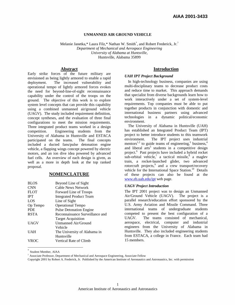
different paths to the cathode. The proton passesthrough the electrolyte. The electrons create aseparate current that can be utilized before theyreturn to the cathode, to be reunited with thehydrogen and oxygen in a molecule of water. This isshown in Figure 8.
A fuel cell system, which includes a «fuel reformer»,can utilize the hydrogen from any hydrocarbon fuel -from natural gas to methanol, and even gasoline.Since the fuel cell relies on chemistry and notcombustion, emissions from this type of a systemwould still be much smaller than emissions from thecleanest fuel combustion processes.
Figure 8. Combustion Process
Not only do they produce reasonable efficiencies in30 kW sizes; they will likely be able to run quietly,need infrequent maintenance, emit little pollution andhave high efficiency even at part load conditions.Electricity is used by many of our modern hightechnology devices. Presently, batteries are used inthese devices. Batteries do not have a long enoughlife for these applications. Fuel cells could providecontinuous power for these devices. Every week ormonth a new supply of liquid fuel would be injectedinto the fuel cell.Fuel cells are being proposed to replace Otto orDiesel engines because they could be reliable, simple,quieter, less polluting, and have even greatereconomy.Fuel cells are most ideal for electric powerproduction because electricity is both the initial andfinal form of energy that is produced.Fuel cells are still a few years away fromcommercialization on a large scale because there arestill some problems to be solved. However, If theseproblems are addressed, fuel cells will becomepredominate propulsion method in the future. In thelast year there has been considerable progress madein this direction.Now, thanks to the progress done, fuel cells reachcharacteristics of weight and compactness compatiblewith our requirements: 1kg/kW and 1dm 3 /kW.17
Considering the power required by the motor whichis 34.5 kW, the fuel cell needed for Oiseau willweigh 35 kg (67 lbs.) and its volume is 35 dm 3.
As companies who build these fuel cells design themfor the specific automotive field, there are still nofuel cells fitting the exact characteristics of Oiseau.
Arthur D. Little says, "The opportunities for furtherimprovements in PEM fuel cell technology areimpressive, further emphasizing the potential role ofthe technology as a major worldwide standardbeyond 2000." 18 Fuel cells can promote energydiversity and transition to renewable energy sources.Hydrogen-the most abundant element on Earth- canbe used directly.
Carbon nanotubes are a new method for the storageof hydrogen. One way carbon can arrange itself is ina sheet pattern like a honeycomb. This is the graphiteform of carbon. The sheets are not bound tightlytogether, but if they are wrapped on top of each other,a very strong carbon nanotube is formed. TerryBaker, professor of chemistry at NortheasternUniversity discovered carbon nanotubes, while Terrywas doing research at the Atomic Energy Authorityin Harwell, England. The carbon was a waste productof catalytic reactions. As a catalytic reaction proceedsplatelets of precipitated carbon stack below andabove the metal particle. Different metals of course,produce different configurations of the platelets. Thecarbon may stack like crackers, some may stackslanted end to end resembling a herringbone, andsome may stack in a bent formation creating tubes. Aconsistent property of the nanofibers is that thedistance between each platelet is identical. The fibersare generally 5-100 micrometers in length and have adiameter of 5-100 nanometers, hence the namecarbon nanotube. It has also been discovered thattreating the nanotubes with nitric acid will open thecaps on the end of the tubes. The interesting partconcerning these carbon nanotubes is that theirwidths are just large enough for hydrogen moleculesbut too small for larger molecules. A typicalhydrogen molecule consists of two hydrogen atoms.The hydrogen atom has the second smallest radius ofall elements because its one electron is in the firstorbital, which is the closest orbital to the positivelycharged nucleus. So the one electron is held verytightly to the nucleus thus decreasing the atomicradius. It is possible then that perhaps hydrogen canbe stored in these carbon nanotubes.
Terry Baker realized the possibility of storage incarbon nanotubes. His research findings haveproduced astounding results they have been able tostore 30 liters of hydrogen in one gram of carbon!This corresponds to approximately 75% hydrogenstorage by weight. At this rate a 25-liter tank which ishalf the size of a gasoline tank and weighs 87-kg can

AIAA 2001-3433
American Institute of Aeronautics and Astronautics11
power a car for 5,000 miles. These experiments havebeen repeated fifty times by Baker.
The following general process is followed to allowhydrogen to be stored in the carbon: The nanotubesare first washed in acid to remove any metalimpurities, they are then heated to 900 degrees C andput under a vacuum to remove any gases that may beslits on the nanofibers. Hydrogen is then pumped intothe system at a pressure of 120 atm. The hydrogencan then be released by gradually reducing thepressure. Note a pressure of 40 atm must be appliedto keep the hydrogen in place. The pressure wherethe hydrogen gas will cease to be released from thecarbon tubes has also yet to be determined .17
Assumption: considering that a 25 liter tank which ishalf the size of a gasoline tank and weighs 87 kg canpower a car for 5,000 miles. And that an electricalengine of such a car required 33 kW (Toyota’s Prius).Oiseau needs the same power but the missionrequires it only to be able to do 36 miles (75 km).Fuel cells produce electricity. This is not the desiredform of energy for transportation. The electricitymust be converted into mechanical power using anelectric motor. The power required at the output ofthe motor for the flapping wings is 32.2 hp. Here arethe references of the motor that we chose: it is anengine designed by the company BLADOR.19
This motor weighs 60 kg (132.3 lbs.), but we canexpect the within 20 years the electrical motor’sweight will be reduced by 10 to 20%20, so we basedour calculation of weight on the value of 112 lbs.The output of the motor is a rotation speed on a shaft;we need to convert this motion into an up and downmotion, so that our wings will flap. Figure 9 is not atscale, but shows the principle of our transmissionsystem.
Figure 9. Principle of Transmission
Team 3 Solution – The PatrocinorThe Patrocinor has been created to meet all of therequirements set forth in the specifications fromAMCOM. The Patrocinor is shown in Figure 10.Patrocinor will get you there, will let you know what
is out there, and will return safely faster, cheaper, andwith higher performance than its competitors. ThisUAGV uses a completely silent ionic propulsionsystem that is powered by the next generation of fuelcells. It incorporates the use of an exoskeletonframework structure for a reduction in weight as wellas for improved survivability. Sensors are imbeddedinto the skin to minimize housing components. Theskin itself is comprised of layers of radar reducingmaterial alongside high strength materials. TheUAGV has good ground mobility and excellentcommunication with home base. Uniquely settingitself apart from its competitors the Ionic Defenderhas a top down thinking process utilizing the bestcompilation of information gathering available. It’sobvious. The Patrocinor delivers. Yes, it challengesits design team to package this cutting-edge vehiclefor reliability but the system uses technology that isalready out there in some form thereby minimizingoverall costs for development.
Figure 10. Team 3 Solution
Money is a good place to start in describing the keyfeatures of the Patrocinor. For an estimated cost of170 mil in today’s U.S. dollars the U.S. Army canhave all of their needed capability by the year 2020.It’s not the cheapest on the market but it is far fromthe most expensive. What AMCOM gets for itsmoney is a vehicle that will change the face ofwarfare forever. Our soldiers will be protected wellbehind the front line while a swarm of IonicDefenders communicate vital information about theenemy in real time back to home base. This comes ata fraction of the cost of some of the military’s otherhigh-tech ventures.
The Patrocinor brings to life ionic propulsion. Thisunique propulsion system has never been used in amilitary application before, but this system has nomoving parts, no emissions, and minimal powerrequirements. Screens are used to charge air particles

AIAA 2001-3433
American Institute of Aeronautics and Astronautics12
in the ducts and accelerate them out the back of thevehicle, in turn propelling the Ionic Defender quietlyand effectively to its destination.
Fuel cells are the propulsion method of choice for theIonic Defender. The decision to use fuel cells cameabout from the power to weight ratios that burdenedthe baseline design. Ultimately, fuel cells are beingheavily researched at this time both by the militaryand commercial venues and they offer the best powerin the smallest sizes and the cheapest costs.Top down thinking is the only way to go. It is afeature that doesn’t increase costs or complication. Itis a methodology that raises reliability immeasurablyand lends itself to the thought processes of themilitary operators who will be handling thePatrocinor. This thought process is unique to thePatrocinor, and developed solely by GRAD Inc. forthe purpose of this unmanned vehicle. The processesare based on requirements set forth in thespecification. The advantages that Patrocinor bringsto the table continue with the choice of materials forfabrication, aerodynamic design, and groundmobility.
PropulsionThe concept of ionizing air to produce a flow hasexisted since the 1950’s. This technology derivedfrom electro-static air cleaners. A high voltagepotential is placed across two grids; the voltagepotential ionizes the surrounding air and causes it toflow though the grids. The second grid is thecollecting grid; the grid attracts solid particles to it.The system easily removes significant amounts ofairborne microscopic debris, thus providing cleanerair.Alexander P. de Seversky patented an electro-staticsystem for propulsion in 1964. Seversky created alarge, lightweight structure applying the abovetechnology. He proved that enough lifting forcecould be produced to sustain flight of a heavier thanair vehicle.21
GRAD Inc. chose ionic propulsion because of itsquiet operation and low power consumption. Theelectro-static system produces no sounds except forthe flowing air. This quality provides the vehiclewith a lower chance of detection by enemy due tonoise. In an article written about Seversky’sinvention the author claimed, “It sat there silently inmidair.”22 Also, the system requires relatively lowpower use. This system when compared to aconventional rotorcraft design uses half the power toprovide the same lift. Another benefit of the systemis that it is less susceptible to damage from projectilesthan a turbine or ducted fan. If a bullet is shot
through the grids only a few wires may be damaged,but the remaining wires can still operate the vehicle.
The ionic propulsion system consists of a highvoltage pulse generator connected to two grids orarrays of wires. A short distance of about four to sixinches separates the grids. The top array has anemitting area approximately twenty times smallerthan the receiving array. The voltage generator sendsa varying positive charge to the top grid, while thebottom grid receives an equal negative charge. Thisvoltage potential ranges from 50kV to 150kV. Thesurrounding air is ionized and pushed through theduct encircling the arrays. The force exiting theengines is adjusted by varying the voltage potentialacross the grids; the higher voltage produces morethrust. This allows the vehicle to lift from theground, to a hover profile, and to a full flight profile.The source for horizontal thrust will be a smallerversion of the engine mounted vertically. Thisengine will duct the airflow similar to a turbojetengine to add additional power.
Preliminary calculations have determined that thepower required for the ionic engines is only 25kW.This is powerful enough to allow a VROC of 250 feetper minute. The horizontal engine will give a speedof 50 kilometers per hour.
Although this technology is not widely known, theionic propulsion system is an easily constructedsystem. There is little maintenance needed; thesystem does not have any moving parts to wear out orbreakdown. With little investment in development ofthe engines, there is the possibility of revolutionizingthe propulsion industry.
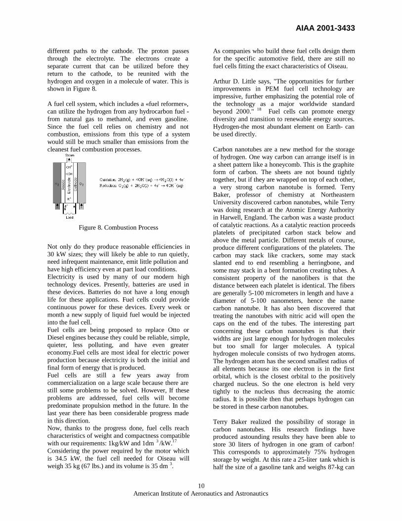
Technical ComparisonsTable 2 summarizes the key characteristics presentedby each of the teams. It also shows the key enablingtechnologies that will need investment to realize theimplementation of the concept.
AIAA 2001-3433
American Institute of Aeronautics and Astronautics13
Table 2. Team Comparisons
Comparison Criteria Team 1 Concept Team 2 Concept Team 3 ConceptAir Configuration Ducted Fans, Wings Flapping Wings Ionic PropulsionGround Configuration Semi-spherical Wheels
on movable strutsMattracks Ionic Propulsion, Landing
StrutsPayload Mass, kg (lb) (27.2) 60 68 lb 60 lbGross Takeoff Weight. kg (lb) (218) 480 332 lb 300 lbEnergy Source for Air Transport Wankel Engine
(hover),PDE (Forward Flight)
Fuel cells PEM Fuel cell
Energy Source for GroundTransport
Wankel Engine Fuel cells PEM Fuel cell
Hovering Power, kW (hp) 83.5(112) 35 kW(47 hp) 22 kW(30 hp)Cruise Power at 15 km/hr , kW,(hp)
74.5 (100) 7.4 kW 23.8 kW
Total Energy for Mission Profile,KJ (BTU)
1.079x10⁶ (1.023x10⁶) 299,259 kJ (283,631BTU)
2.564x10⁵ kJ(2.43x10⁵)BTU)
Basis of Autonomy Computer MACC Thinking processPrimary BLOS Method HF band “Spy Oiseau” Ultra-Wide BandPrimary Structural Material Titanium, ABS plastic Magnesium and Carbon
FiberCarbon Fiber
Enabling Technology 1 PDE using heavy fuels Fuel Cells and ElectricMotors
Ionic Propulsion
Enabling Technology 2 Muffler Technologyfor PDE
Piezoelectric Material Fuel Cells
Enabling Technology 3 Wing Material Ultra-Wide BandEnabling Technology 4 Chip on Flex Sensors Vehicle SkinStructure Titanium Magnesium Alloy and
Carbon FiberCarbon Fiber
Fuel Weight 1.6 lbsRange 75 km 30 km
Selection of the Preferred ConceptAn Industrial Review Team selected the concept ofTeams 2 as the best overall design. The reviewersmade their evaluations based on a 50-page report andan oral presentation by each team. The usedevaluation criteria based on the AIAA DesignCompetition that had been modified for this specificcontest. The evaluation criteria included: technicalcontent, organization/presentation, originality, andfeasibility. Since the specification allowed adeployment in the year 2025, the teams could projecttechnologies in their presentations.
The Review Team liked the use of the Wankle engineto provide power for both the air and ground mode onthe Team 1 design. The technology projections wereclearly presented and the report presented in a logicalsequence. Challenges in driving the ducted fan andthe wheels with the same RPM engine were noted
along with the acoustic signature of the pulse-detonation engine.
The Review Team liked the bold, imaginativeapproach of team 2. The saw their reports wasconcise and well written. The concept alsomaximized the use of available development time toachieve the technology advances. They liked theelectronic drive the operations scenarios given.Challenges in mitigating the technical risk and thestability of the platform were concerns.
The Review Team though that Team 3 had a novelapproach to the customer requirements. The concepthad a good mix of the state of the art with reasonableexpectations for future technology development. Thepresentation of the material did not make clear thestate of the art in ion propulsion and did not have acohesive style. The use of ion propulsion for the

AIAA 2001-3433
12
Figure 11 Key Features of the Oiseau
ground mobility fulfilled the basic operationalrequirements
Based using the evaluation criteria the ReviewTeamed named Team 2’s proposal for the Oiseau asthe top concept. The teams were all commended fortheir novel ideas and broad look at possibilities forfulfilling the project requirements.
Implementation of Preferred Concept
Figure 11shows the features of the Team 2 Oiseau.The vehicle is 16 feet wide and 5 feet long.
Operations ScenarioThe assumed mission profile is for the vehicle totakeoff vertically close to the FLOT, climb at 250fpm to a maximum altitude of 500 ft AGL (at highhot conditions), and cruise at 30 km/hr for 30 minutes(15 km range). The vehicle will then either hover for60 minutes or land, traverse the ground, and takeoffagain and then fly back to the departure point. Thesensor package and payload capacity will give theOiseau considerable flexibility in terms of theoperations it can perform.
Performance
Table 3. Final Concept Evaluation
CDDRequirement
Requirement Assessment
Range fromlaunch point
15 km 30 km
Cruise Speed 30 km/hr 40km/hrVROC 250 ft/min 360 ft/minVTOL Capability Yes YesPayload: 60 lb 68 lbOperationalAltitude
0 to 500 ft AGL 0 to 500 ftAGL
Hover to full flightprofile
Yes Yes
Operation Autonomous orSemi-
autonomous
Autonomousor Semi-
autonomousAcousticSignature
Near Quiet Moderate toNear Quiet
Communications BLOS BLOSDeployment 2025 2025
The ImplementationThere are several technologies whose furtherdevelopment is critical to the development of the
Tracked GroundMobility that canovercome mostobstacles
State of the ArtSensor Package (foreand aft)
Dual Flapping Wings withpiezoelectric wing warping
Active Camouflage thatcan assume any visiblecolor at a momentsnotice
Lightweight Magnesium Alloyframe with Carbon Fiber body
Modular body and wingsystem that allows easydetachment and access tointerior
High efficiency, fuel celltechnology for quiet power

AIAA 2001-3433
13
Oiseau. One such technology is lightweight fuel cellsand electrical motors. Fuel cells have been used forquite some time in spacecraft for the generation ofelectrical power; however, some adaptations areneeded for the Oiseau. Although operatingcharacteristics of electric motors are widelyunderstood, a specific motor will have to bedeveloped that is optimized for flight (i.e. high powerto weight ratio, etc.). Another technology currentlyunder development is Integrated Vehicle HealthManagement (IVHM). This is a computer softwaresystem that records: fault messages with LineReplaceable Units (LRUs) isolation, parametric andperformance data, and warnings, cautions, andadvisories.23 This system can be used not only toschedule preventative maintenance, but to optimizesub-system performance as well. Another technologyrequired is piezoelectric materials to be used by thecontrol system. These materials, also currently underdevelopment, distort their shape when voltage isapplied to them. Such devices will be built into theflexible wings. This will yield control over camberfor aerodynamic effects and wing warping forcontrols.
Further technological development required includeswing material and lighter structural materials. Therequirements for the wing material are unique.Directional gas permeability is required foraerodynamic reasons. There exist fabrics capable ofsuch characteristics; however, better performance is,of course, needed. Lighter materials in general couldgreatly effect the performance characteristics of theOiseau. Current research in this topic is broad andthe shows much potential.
The next area of study needed is the development ofsoftware that can handle the autonomous operation ofa UAGV. There is considerable development ofsoftware in the commercial arena. Advance avionicspackages should be developed to control the vehicleas it flies as well as coordinate the ground robotics.There are considerable advantages to using flappingwing flight. However, there is considerable researchwork needed to fully implement the design. With ananticipated deployment date of 2025, there is ampletime to complete supporting research. With thisintended deployment date, detailed design will needto occur by 2016. The technology must then beavailable by this date to fulfill the specification.More specifically, the electrical propulsion system’sresearch should be completed in the next 10 years (by2011). The research for the wing material must bedone in the next 12 years as well to allow for testingbefore detailed design begins. The software shouldbe developed by 2011 as well and tested in an
existing vehicle before 2014. The avionics should bedeveloped in parallel with the software. Thecombination of the software and avionics should betested before 2016.
AcknowledgementsThe project was supported with a grant from the U.S.Army Aviation and Missile Command. The contractmanagers were John Fulda and James Winkeler.Sverdrup Technology provided support for an OpenHouse Event. The Redstone Chapter of the AmericanHelicopter Society sponsored an awards luncheon torecognize the students. The UAH StudentGovernment Association provided money for studenttravel. Marie-Sophie Pawlak at ESTACA providedfinancial support for travel.
This project involved forty-four students from UAHand ESTACA who worked on the integrated productTeams including: Akmal Abdulakhatov, CyrilAugier, Jason Back, Majed Batais, Ben Bramblett,Segolene Branstchen, Kevin Buch, Jean-EmmanuelBzdrega, Joe Caldwell, Shane Canerday, YounesElkacimi, Laura Filz (Team 1 Leader), JulienGeffard, Brian Griffin, Timur Hakimov, TimothyHardin, Matthew Harris, Damon Hay, Chris Hirstein,Francois-Xavier Hussenet, Pierrot Ivoula, MelanieJanetka (Team 2 Leader), Jon Kilpatrick, JamesKodrowski, Sebastian Kriner, KannathasKrishnassamy, Shane Lackey, Sheree Long,Kristopher McDougal, Jason Newton, AngelineNuar, Demetrius Peoples, Rajat Sharma, NathanSmith (Team 3 Leader), Richie Sparkman, LindaTaylor, William Thomas, Cedric Trophardy, CedericVanEssen, Nicholas Vergenealt, Pascal Vidal,Timothy Weaver, Virgil White, Khalid Zarouni.
AMCOM personnel participated as mentors givingbrief lectures to the class and serving as consultantsthroughout the project. They were John Berry, JohnCarter, Jim Dingess, John Fulda (Lead), JimKirkwood, Pat McInnis, Alfred Reed, Jim Winkeler(Co-Lead), and Virginia Young.
Mentors from other companies include: SherryAdlich (Teledyne Brown Engineering), PhillipFarrington (UAH-ISE Dept.), Frendi Kader (UAH-MAE Dept.), Alex Maciel (SSAI Sigma Services ofAmerica, Inc.), John Piccarillo (UAH-ECE Dept.),Jim Sanders (UAH Propulsion Research Center),George R. Smith (Smith Enterprises).
The Design Review Team consisted of IndustryExperts as follows: Lawrence Bavis (CAS Inc.), Dr.Henry L. Pugh (The Boeing Company), Dr. M. FrankRose (NASA MSFC), Jan VanAken (NASA Ames),

AIAA 2001-3433
14
Mr. David Weller (AMCOM AMRDEC – Lead), Dr.Virginia Young (AMCOM).
The following people served active support roles indeveloping Internet communications andadministrative support for the class:, Alex MacielBob Middleton, Ina Ryzhkova, Ilya Shkolnikov,James Williamson, Beth Floyd, Brandy Carder, SuziBonn, and Sarah Paul.
The following faculty lead classes that wereintegrated together for this project Dave Berkowitz,Administrative Sciences; Paul Componation,Industrial and Systems Engineering; Charles D.Corsetti, Electrical and Computer Engineering;Robert Frederick – Lead, Mechanical and Aerospaceengineering; Rose Norman, English; Marie-SophiePawlak, ESTACA International Director; DawnUtley Industrial and Systems Engineering; and EarlWells, Electrical and Computer Engineering.
References 1 Frederick, R. A., Jr. and Sanders, J., "The EffectiveUse of Mentors in Undergraduate Design" 1993ASME Winter Annual Meeting, AES Vol. 30/HTDVol. 226, Thermodynamics, Analysis, andImprovement of Energy Systems, pp. 219-225, NewOrleans, November 28 to December 3, 1993.2 Frederick,R.A., Jr., Evans, D.A., and Norman, R.L.,“Multi-College Design Class with IndustrialMentors,” 32nd AIAA/ASME/ASEE JointPropulsion Conference and Exhibit, Lake BuneaVista, FL, AIAA Paper No. 96-2560, July 1-3, 1996.3 Frederick ,R.A., Jr., Evans, D.A., and Norman,R.L., “Multi-Agency, Integrated Product Teams,”paper accepted by Stanley L. Proctor, ABETPresident Elect, Innovations in EngineeringEducation, Accreditation Board for Engineering andTechnology (ABET) 1996 Annual Meeting, SanDiego, CA; October 31 to November 1, 1996, pp.165-171.4 Frederick, R.A., Jr., Evans, D.A., Norman, R,“Integrating Business and Engineering Education,”Invited Panel Discussion, Decision Sciences Institute,27th Annual Meeting, Orlando, FL November 24-26,1996.5 Norman, Rose, and Frederick. Robert A.“Integrating Technical Editing Students in aMultidisciplinary Engineering Project.” TechnicalCommunication Quarterly 9.2 (Spring 2000): 163-89.6 Frederick, R.A., Jr., Takada, P., and Cook, L., "Prototype for a Multi-National Propulsion SystemDesign Course," AIAA Paper 2000-TBD,AIAA/ASME/SAE/ASEE Joint PropulsionConference and Exhibit, July 16-19, 2000.
7 Paxton, J., Achenbach, Patterson, P., M. Pyburn, J.,Thomas, M., and Frederick, R. A., Jr., "Design ofTurbopump-Fed Hybrid Launch Vehicle," AIAA 93-2549, AIAA/SAE/ASME/ASEE 29th JointPropulsion Conference and Exhibit, Monterey, CA,June 28-30, 1993.8 Sims, J.D. and Frederick, R.A., “Preliminary Designof a Hybrid Propulsion System for a Multi-MissionMissile System,” March-April AIAA Journal ofSpacecraft and Rockets, 1997.9 Frederick, R.A., Jr., Davis, K., Hopper, M., andSymes, A., "Preliminary Design of Rotorcraft withMulti-Disciplinary, International Teams," AIAAPaper No. 99-2845, June 20-23, 1999.10 Thomas, S., Bollich, J., Popo, M., and Frederick,R.A., Jr., " International Space Station CrewTransfer/Recovery Vehicle," AIAA Paper AIAA-2000-3741, AIAA/ASME/SAE/ASEE JointPropulsion Conference and Exhibit, July 16-19, 2000.11 Georgia Institute of Technology; Article attributedto Robert Michelson,gtresearchnews.gatech.edu/reshor/rh-spr97/microfly.htm. Accessed: February 10, 2001.12 Brophy, Christopher, Interviewed by Dr. RobertFrederick, Huntsville, AL. April 13, 200113 Eidelman, S. and Grossman, W., “PulsedDetonation Engine – Experimental and TheoreticalReview,” AIAA Paper AIAA 92-3168,AIAA/SAE/ASME/ASEE Joint PropulsionConference and Exhibit, Nashville, TN, July 6-8,1992.14 Moser, Marlow. Interviewed by Tim Hardin.Huntsville, AL, April 2001.15 Bussing, T. and Pappas, G., “An Introduction toPulse Detonation Engines,” 32nd Aerospace SciencesMeeting and Exhibit, Reno, NV, January 10-13,1994.16 http:// www.fuelcells.org. Accessed April 10, 2001.17 Bezian, Jean Jacques, Centre d’Energetique del’Ecole des Mines de Paris. “Systemes de piles acombustible pour la cogeneration,” October 31, 1998.18 Little, Arthur D., “PEM Fuel Cell Technology forTransportation Applications” Status and prospects,1996.
19 http:// www.blador.com/information . AccessedApril 14, 2001.20 Mr. Bonofos teacher and Dean of the Motor enginelaboratory at SUPELEC Paris21 DeSeversky, Alexander. Ioncraft. United StatesPatent and Trademark office. U.S. Patent No.3,130,945. April 28, 1964.22 Fantel, Hans, “Major de Seversky’s Ion PropelledAircraft”, Popular Mechanics. August 1964.23http://technology.ksc.nasa.gov/wwwaccess/techreports/97/07-EI/ei07.html accessed 10 April 2001


![Common Ground Control Station for Unmanned Aerial Vehicle [UAV] Operation](https://static.fdocuments.in/doc/165x107/544bfa78af7959b0438b57a4/common-ground-control-station-for-unmanned-aerial-vehicle-uav-operation.jpg)