CONCRETE PUMP - K2 Development Technologies
110
OPERATION AND PARTS MANUAL Revision #1 (07/11/07) SERIES MODEL C-30HDG CONCRETE PUMP THIS MANUAL MUST ACCOMPANY THE EQUIPMENT AT ALL TIMES. To find the latest revision of this publication, visit our website at: www.multiquip.com
Transcript of CONCRETE PUMP - K2 Development Technologies

OPERATION AND PARTS MANUAL
Revision #1 (07/11/07)
SERIESMODEL C-30HDG
CONCRETE PUMP
THIS MANUAL MUST ACCOMPANY THE EQUIPMENT AT ALL TIMES.
To find the latest revision of thispublication, visit our website at:
www.multiquip.com
PAGE 2 — MAYCO C-30HDG PUMP — OPERATION AND PARTS MANUAL — REV. #1 (07/11/07)
C-30HDG PUMP — PROPOSITION 65 WARNING

MAYCO C-30HDG PUMP — OPERATION AND PARTS MANUAL — REV. #1 (07/11/07) — PAGE 3
Grinding/cutting/drilling of masonry, concrete, metal andother materials with silica in their composition may giveoff dust or mists containing crystalline silica. Silica is abasic component of sand, quartz, brick clay, granite andnumerous other minerals and rocks. Repeated and/orsubstantial inhalation of airborne crystalline silica cancause serious or fatal respiratory diseases, includingsilicosis. In addition, California and some otherauthorities have listed respirable crystalline silica as asubstance known to cause cancer. When cutting suchmaterials, always follow the respiratory precautionsmentioned above.
WARNING
Grinding/cutting/drilling of masonry, concrete, metal andother materials can generate dust, mists and fumescontaining chemicals known to cause serious or fatalinjury or illness, such as respiratory disease, cancer,birth defects or other reproductive harm. If you areunfamiliar with the risks associated with the particularprocess and/or material being cut or the composition ofthe tool being used, review the material safety datasheet and/or consult your employer, the materialmanufacturer/supplier, governmental agencies such asOSHA and NIOSH and other sources on hazardousmaterials. California and some other authorities, forinstance, have published lists of substances known tocause cancer, reproductive toxicity, or other harmfuleffects.
Control dust, mist and fumes at the source wherepossible. In this regard use good work practices andfollow the recommendations of the manufacturers orsuppliers, OSHA/NIOSH, and occupational and tradeassociations. Water should be used for dustsuppression when wet cutting is feasible. When thehazards from inhalation of dust, mists and fumes cannotbe eliminated, the operator and any bystanders shouldalways wear a respirator approved by NIOSH/MSHA forthe materials being used.
WARNING
SILICOSIS WARNING RESPIRATORY HAZARDS
C-30HDG PUMP — SILICOSIS/RESPIRATORY WARNINGS

PAGE 4 — MAYCO C-30HDG PUMP — OPERATION AND PARTS MANUAL — REV. #1 (07/11/07)
MAYCO C-30HDG (ZENITH)CONCRETE PUMPProposition 65 Warning ..............................................2Silicosis/Respiratory Warnings ...................................3Table of Contents .......................................................4Parts Ordering Procedures ........................................5Pump Specifications ...................................................6Engine Specifications .................................................6Pump Dimensions ......................................................7Safety Message Alert Symbols .............................. 8-9Rules For Safe Operation .................................. 10-12Towing Guidelines .............................................. 14-15Trailer Safety Guidelines .................................... 16-18Operation And Safety Decals ...................................20Important Hand Signals ...........................................21Pump Components ............................................ 22-23Control Box Components .........................................24Engine Components ................................................25General Information .................................................26How It Works ...................................................... 27-28Operating Information ........................................ 29-33Inspection ........................................................... 34-36Startup ............................................................... 36-37Shutdown Procedures..............................................37Maintenance (Pump) ......................................... 38-47Engine Troubleshooting...................................... 48-49Engine Fault Codes ............................................. 50-53Wiring Diagram (Zenith Wiring Harness) ........... 54-55Wiring Diagram ........................................................56Wiring Diagram (Tail Lights) .....................................57Appendix —
Slump Test Procedure ........................................58Concrete Mix Information ............................ 59-61Recommended Shotcrete System ............... 62-63Recommended Shotcrete Accessories ........ 64-65
Explanation of Codes in Remarks Column ..............66Suggested Spare Parts ............................................67
TABLE OF CONTENTS
Specification and part number are subjectto change without notice.
COMPONENT DRAWINGSNameplate and Decals ....................................... 68-69Compensator Piston Rod Assembly .................. 70-71Connecting Rod - Drive Side Assembly ............. 72-73Rocker Assembly ............................................... 74-75Countershaft Assembly ...................................... 76-77Crankshaft Assembly ......................................... 78-79Manifold Assembly ............................................. 80-81Frame Assembly ................................................ 82-83Axle Assembly .................................................... 84-85Muffler, Air filter And Stop Switch Assembly ...... 86-87Clutch Assy ........................................................ 88-89Engine Mounting Brackets Assembly ................ 90-91Radiator, Mounting Bracket And Hoses Assy .... 92-93Control Box Assembly ........................................ 94-95Battery Assembly ............................................... 96-97Fuel Tank Assembly ........................................... 98-99Hopper Assy................................................... 100-101Hood Assembly .............................................. 102-103Lubrication Panel Assembly ........................... 104-105Remote Control Cable Assembly ................... 106-107
Terms and Conditions Of Sale — Parts .................108Mayco Pump Warranty ...........................................109

MAYCO C-30HDG PUMP — OPERATION AND PARTS MANUAL — REV. #1 (07/11/07) — PAGE 5
ww
w.m
ultiq
uip
.com
Ordering parts has never been easier!Choose from three easy options:
WE ACCEPT ALL MAJOR CREDIT CARDS!
When ordering parts, please supply:❒❒❒❒❒ Dealer Account Number
❒❒❒❒❒ Dealer Name and Address
❒❒❒❒❒ Shipping Address (if different than billing address)❒❒❒❒❒ Return Fax Number❒❒❒❒❒ Applicable Model Number
❒❒❒❒❒ Quantity, Part Number and Description of Each Part
❒❒❒❒❒ Specify Preferred Method of Shipment:✓ UPS/Fed Ex ✓ DHL
■ Priority One ✓ Truck■ Ground■ Next Day■ Second/Third Day
All orders are treated as Standard Ordersand will ship the same day if received priorto 3PM PST.
If you have an MQ Account, to obtain aUsername and Password, E-mail us at:[email protected].
To obtain an MQ Account, contact yourDistrict Sales Manager for more information.
Order via Internet (Dealers Only):Order parts on-line using Multiquip’s SmartEquip website!
■ View Parts Diagrams■ Order Parts■ Print Specification Information
Note: Discounts Are Subject To Change
Goto www.multiquip.com and click on
Order Parts to log in and save!
Use the internet and qualify for a 5% Discounton Standard orders for all orders which includecomplete part numbers.*
Order via Fax (Dealers Only):All customers are welcome to order parts via Fax.Domestic (US) Customers dial:1-800-6-PARTS-7 (800-672-7877)
Fax your order in and qualify for a 2% Discounton Standard orders for all orders which includecomplete part numbers.*
Order via Phone: Domestic (US) Dealers Call:1-800-427-1244
Best Deal!
International Customers should contacttheir local Multiquip Representatives forParts Ordering information.
Non-Dealer Customers:Contact your local Multiquip Dealer forparts or call 800-427-1244 for help inlocating a dealer near you.
Note: Discounts Are Subject To Change
Effective:January 1st, 2006
PARTS ORDERING PROCEDURES

PAGE 6 — MAYCO C-30HDG PUMP — OPERATION AND PARTS MANUAL — REV. #1 (07/11/07)
C-30HDG PUMP — PUMP SPECIFICATIONS
SNOITACIFICEPSPMUPGDH03-C.1ELBATepyTpmuP notsiPgnitacorpiceR
etaRgnipmuP *ruohrep.sdy.uc52otpU
thgieHgnipmuPlacitreV )m37.54(.tf051otpU
ecnatsiDgnipmuPlatnoziroH *)m251-221(.tf005-004
eziSetagerggAmumixaM )mm7.21(sunim.ni2/1
yticapaCreppoH .cte.tf.uc6
esoHlairetaM"2/1-2ro"2
)mm5.36ro8.05(
thgieW )gK833,1(.sbl059,2
xoBlioebuL )sretiL5.62(snollaG7
lortnoCetomeR dradnatSelbac.tf521
eziSeriT"41x"53.7
)mm653x781(
ezisenil,pmuls,ngisedximnognidnepedyravlliwtuptuoemuloV*.snoitidnocetisbojdnadesu
SNOITACIFICEPSENIGNE.2ELBAT
enignE
ledoM ENIGNE614HTINEZ
epyTednilycelgnis,evlavdaehrevo,ekorts4
enigneenilosagtfahslatnoziroh
ekortSXeroB.ni32.3x99.2)mm28x67(
oitaRnoisserpmoC 1:01
tnemecalpsiD )cc995,1(.uc6.79
tuptuOsuounitnoC [email protected]
yticapaCknaTleuF )sretil24(snollaG.S.U11.xorppA
epyTleuF enilosaGdedaelnU
yticapaCliOebuL )sretil7.3(.stq9.3
deepSenignEdaoLlluF
)05-/+mpr0572daoLoN(001±mpr0562)001-/+mpr0572daoL(
deepSenignEeldIlluF
001±mpr578
renaelCriA epyTnroHriA
noitacirbuLenignE)edarGliO(03-W01EAS)ssalCecivreS(FSroGS
dohteMgnitratS tratScirtcelE
gulPkrapS SE4B
paGgulPkrapS.ni9.0-8.0
)mm530.0-130.0(
)HxWxL(noisnemiD.ni08.52x05.22x01.02
)mm5.456x5.725x9.905(
thgieWteNyrD ).gK3.621(sbl871

MAYCO C-30HDG PUMP — OPERATION AND PARTS MANUAL — REV. #1 (07/11/07) — PAGE 7
C-30HDG PUMP — PUMP DIMENSIONS
Figure 1. C-30HDG Concrete Pump Dimensions

PAGE 8 — MAYCO C-30HDG PUMP — OPERATION AND PARTS MANUAL — REV. #1 (07/11/07)
C-30HDG PUMP — SAFETY MESSAGE ALERT SYMBOLS
Safety precautions should be followed at all times when operatingthis equipment. Failure to read and understand the SafetyMessages and Operating Instructions could result in injury toyourself and others.
FOR YOUR SAFETY AND THE SAFETY OF OTHERS!
SAFETY MESSAGE ALERT SYMBOLS
The three (3) Safety Messages shown below will inform youabout potential hazards that could injure you or others. The SafetyMessages specifically address the level of exposure to theoperator, and are preceded by one of three words: DANGER,WARNING, or CAUTION.
You WILL be KILLED or SERIOUSLY injured if you donot follow directions.
You COULD be KILLED or SERIOUSLY injured if youdo not follow directions.
You CAN be injured if you do not follow directions
HAZARD SYMBOLS
Gasoline engine exhaust gases containpoisonous carbon monoxide. This gas iscolorless and odorless, and can causedeath if inhaled. NEVER operate thisequipment in a confined area or enclosed
structure that does not provide ample free flow air.
Potential hazards associated with operation of the pump will bereferenced with Hazard Symbols which appear throughout thismanual, and will be referenced in conjunction with SafetyMessage Alert Symbols. Some examples are listed below:
Gasoline is extremely flammable, and itsvapors can cause an explosion if ignited.DO NOT start the engine near spilled fuelor combustible fluids. DO NOT fill the fueltank while the engine is running or hot.
DO NOT overfill tank, since spilled fuelcould ignite if it comes into contact with hot engine parts orsparks from the ignition system. Store fuel in approvedcontainers, in well-ventilated areas and away from sparks andflames. NEVER use fuel as a cleaning agent.
Engine components can generate extremeheat. To prevent burns, DO NOT touch theseareas while the engine is running orimmediately after operations. NEVER operatethe engine with heat shields or heat guardsremoved.
WARNING
DANGER
CAUTION
WARNING - LETHAL EXHAUST GASES
WARNING - BURN HAZARDS
WARNING - EXPLOSIVE FUEL
NOTE
This Owner's Manual has beendeveloped to provide completeinstructions for the safe and efficientoperation of the Mayco ModelC-30HDG Concrete Pump.
Refer to the engine manufacturers instructions for data relativeto its safe operation.
Before using this pump, ensure that the operating individualhas read and understands all instructions in this manual.

MAYCO C-30HDG PUMP — OPERATION AND PARTS MANUAL — REV. #1 (07/11/07) — PAGE 9
C-30HDG PUMP — SAFETY MESSAGE ALERT SYMBOLS
ALWAYS place the Engine ON/OFF switchin the OFF position and remove the ignitionkey when the pump is not in use.
ALWAYS wear approved respiratoryprotection.
ALWAYS wear approved eye andhearing protection.
Other important messages are provided throughout this manualto help prevent damage to your concrete pump, other property,or the surrounding environment.
This pump, other property, or the surroundingenvironment could be damaged if you do notfollow instructions.
NEVER tamper with the factory settings ofthe engine governor or settings. Personalinjury and damage to the engine orequipment can result if operating in speedranges above maximum allowable.
CAUTION - OVER-SPEED CONDITIONS
CAUTION - ACCIDENTAL STARTING
CAUTION - RESPIRATORY HAZARDS
CAUTION - SIGHT AND HEARING HAZARDS
CAUTION - EQUIPMENT DAMAGE MESSAGES
NEVER operate equipment with covers,or guards removed. Keep fingers, hands,hair and clothing away from all movingparts to prevent injury.
WARNING - ROTATING PARTS
PAGE 10 — MAYCO C-30HDG PUMP — OPERATION AND PARTS MANUAL — REV. #1 (07/11/07)
C-30HDG PUMP — RULES FOR SAFE OPERATION
The following safety guidelines should always be used whenoperating the Mayco C-30HDG Concrete Pump:
General Safety
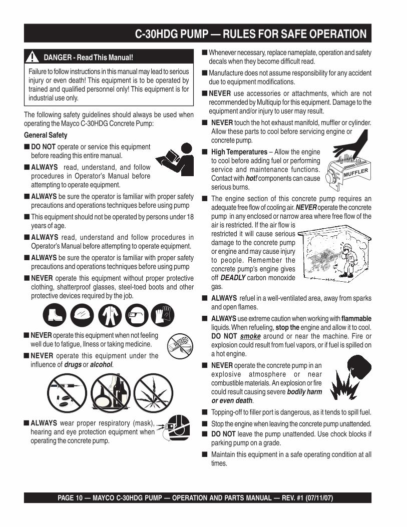
■ DO NOT operate or service this equipmentbefore reading this entire manual.
■ ALWAYS read, understand, and followprocedures in Operator’s Manual beforeattempting to operate equipment.
■ ALWAYS be sure the operator is familiar with proper safetyprecautions and operations techniques before using pump
■ This equipment should not be operated by persons under 18years of age.
■ ALWAYS read, understand and follow procedures inOperator’s Manual before attempting to operate equipment.
■ ALWAYS be sure the operator is familiar with proper safetyprecautions and operations techniques before using pump
■ NEVER operate this equipment without proper protectiveclothing, shatterproof glasses, steel-toed boots and otherprotective devices required by the job.
Failure to follow instructions in this manual may lead to seriousinjury or even death! This equipment is to be operated bytrained and qualified personnel only! This equipment is forindustrial use only.
■ ALWAYS wear proper respiratory (mask),hearing and eye protection equipment whenoperating the concrete pump.
■ NEVER operate this equipment when not feelingwell due to fatigue, llness or taking medicine.
■ NEVER operate this equipment under theinfluence of drugs or alcohol.
DANGER - Read This Manual!■ Whenever necessary, replace nameplate, operation and safety
decals when they become difficult read.
■ Manufacture does not assume responsibility for any accidentdue to equipment modifications.
■ NEVER use accessories or attachments, which are notrecommended by Multiquip for this equipment. Damage to theequipment and/or injury to user may result.
■ NEVER touch the hot exhaust manifold, muffler or cylinder.Allow these parts to cool before servicing engine orconcrete pump.
■ High Temperatures – Allow the engineto cool before adding fuel or performingservice and maintenance functions.Contact with hot! components can causeserious burns.
■ The engine section of this concrete pump requires anadequate free flow of cooling air. NEVER operate the concretepump in any enclosed or narrow area where free flow of theair is restricted. If the air flow isrestricted it will cause seriousdamage to the concrete pumpor engine and may cause injuryto people. Remember theconcrete pump's engine givesoff DEADLY carbon monoxidegas.
■ ALWAYS refuel in a well-ventilated area, away from sparksand open flames.
■ ALWAYS use extreme caution when working with flammableliquids. When refueling, stop the engine and allow it to cool.DO NOT smoke around or near the machine. Fire orexplosion could result from fuel vapors, or if fuel is spilled ona hot engine.
■ NEVER operate the concrete pump in anexplosive atmosphere or nearcombustible materials. An explosion or firecould result causing severe bodily harmor even death.
■ Topping-off to filler port is dangerous, as it tends to spill fuel.
■ Stop the engine when leaving the concrete pump unattended.■ DO NOT leave the pump unattended. Use chock blocks if
parking pump on a grade.
■ Maintain this equipment in a safe operating condition at alltimes.

MAYCO C-30HDG PUMP — OPERATION AND PARTS MANUAL — REV. #1 (07/11/07) — PAGE 11
C-30HDG PUMP — RULES FOR SAFE OPERATION■ CAUTION must always be observed while servicing this
pump. Rotating parts can cause injury if contacted.
■ ALWAYS stored the pump in a clean, dry location out of thereach of children.
■ ALWAYS use extreme care when operating near obstructions,on slippery surfaces, grades and side slopes.
■ Unauthorized equipment modifications will void allwarranties.
■ Refer to the Engine Owner's Manual for engine technicalquestions or information.
■ Before start-up, check the hopper and remove all obstructions.
■ Keep all hands out of the hopper when the engine is running.
■ DO NOT operate the pump with the hood open.
■ Replace any worn or damaged pump componentsimmediately.
■ ALWAYS turn the engine OFF before performing must bebefore performing maintenance.
■ ALWAYS make sure pump is correctly secured to the trailer.Check all supports attaching the pump to the trailer and makesure they are tight.
■ ALWAYS make sure that the pump's trailer is placed on solidlevel ground so that it cannot slide or shift around, endangeringworkers. Place blocks under the trailer's bumper to make itlevel (prevents tipping), and use a chocked block underneaththe wheels to prevent rolling. Also keep the immediate areafree of bystanders.
■ Before towing, check the hitch and secure the safety chain tothe towing vehicle. Also check for proper tire pressure.
■ Tow only with a vehicle and hitch rated to tow a 2,950 lbs.(1,338 Kg) load.
■ If pump is equipped with ball hitch coupler, use only a 2” allsteel ball rated for a minimum of 5000 lbs. Use a 1” hardenedsteel pull pin, if the pump is equipped with a pin hitch.
■ ALWAYS check the machine for loosened threads or boltsbefore starting.
■ A copy of this manual shall accompany the pump at all times.
■ DO NOT use worn out hoses or couplings; inspect daily.
■ DO NOT disconnect the hose couplings or nozzle while theyare under pressure. Relieve the pressure by manuallyswinging the clamp arm latch handle to the first open positionat the exhaust cone outlet.
■ The pump should NEVER be towed in excess of 45 MPH (orless depending on road conditions).
■ If hose lines are blocked for any reason, or if the lines arekinked when starting up or during pumping cycle, the pumppressure could straighten out the kink or force out the blockage.This rapid surge of material could cause the lines to move orwhip in a manner that could cause injury to personnel.
■ Inspect the hose lines at all times
■ DO NOT tow the pump with the hopper full of material.
■ DO NOT tow the pump with the hoses attached.
■ NEVER disconnect any emergency or safety devices.These devices are intended for operator safety. Disconnectionof these devices can cause severe injury, bodily harm or evendeath! Disconnection of any of these devices will void allwarranties.
■ ALWAYS make sure the delivery system used, pipe hoseclamps ect., exceed the rated pressure of the pump. In additionthe pumping system should be checked for worn componentsprior to start up.

PAGE 12 — MAYCO C-30HDG PUMP — OPERATION AND PARTS MANUAL — REV. #1 (07/11/07)
Emergencies
■ ALWAYS know the location of the nearest fire extinguisherand first aid kit. Know the location of the nearest telephone.Also know the phone numbers of the nearest ambulance,doctor and fire department. This information will beinvaluable in the case of an emergency.
Maintenance Safety
■ NEVER lubricate components or attempt service on a runningmachine.
■ ALWAYS allow the machine a proper amount of time to coolbefore servicing.
■ Keep the machinery in proper running condition.
■ Fix damage to the machine immediately and always replacebroken parts.
■ Dispose of hazardous waste properly. Examples of potentiallyhazardous waste are used motor oil, fuel and fuel filters.
■ DO NOT use food or plastic containers to dispose ofhazardous waste.
■ DO NOT pour waste, oil or fuel directly onto the ground,down a drain or into any water source.
Lifting
■ The pump has an operating weight of approximately 2,950lbs. (1,338 Kg). Use lifting equipment capable of lifting thisweight.
C-30HDG PUMP — RULES FOR SAFE OPERATION

MAYCO C-30HDG PUMP — OPERATION AND PARTS MANUAL — REV. #1 (07/11/07) — PAGE 13
NOTE PAGE

PAGE 14 — MAYCO C-30HDG PUMP — OPERATION AND PARTS MANUAL — REV. #1 (07/11/07)
C-30HDG PUMP — TOWING GUIDELINES
To reduce the possibility of an accident while transporting thepump on public roads, always make sure that the trailer and thetowing vehicle are in good operating condition and both unitsare mechanically sound.
The following list of suggestions should be used when towingthe pump:
■ Make sure that the hitch and coupling of the towing vehicleare rated equal to, or greater than the trailer "gross vehicleweight rating" (GVWR).
■ ALWAYS inspect the hitch and coupling for wear. NEVERtow the light tower's trailer with defective hitches, couplings,chains etc.
■ CHECK the tire air pressure on both the towing vehicle andthe trailer. Also check the tire tread wear on both vehicles.
■ ALWAYS make sure the trailer section of the pump isequipped with a "Safety Chain".
■ ALWAYS attach trailer's safety chain to frame of towingvehicle.
■ ALWAYS make sure that the vehicle and trailer directional,backup, brake, and trailer lights are connected properly andare working properly.
■ Remember in most cases the maximum speed unlessotherwise posted for highway towing is 45 MPH, howeverbefore towing your pump, check your local state, and countyvehicle towing requirements. Recommended off-road towingis not to exceed 10 MPH or less depending on type of terrain.
■ Place chocked blocks underneath wheel to prevent rolling,while parked.
■ Depending on soil conditions and location it may benecessary to place support blocks underneath the trailer'sbumper to prevent tipping, while parked.
■ Inflate tires to correct pressure, inspect tires for cuts, andexcessive wear. See Table 3 (Tire Wear Troubleshooting).
Towing Safety Precautions
Pump Trailer Vehicle Connection
1. Check the vehicle hitch ball, and trailer coupler for signs ofwear or damage. Replace any parts that are worn ordamaged before towing.
2. Use only the 2-inch ball diameter with a towing capability of5,000 lbs. (2,268 kg) as indicated on the trailer's coupler.Use of any other ball diameter will create an extremelydangerous condition which can result in separation of thecoupler and ball or ball failure.
3. Be sure the coupler is secured to the hitch ball and the locklever is down (locked).
4. Attach safety chains as shown in Figure 2. Remember tocross the safety chains.
5. After towing for about 50 miles recheck the entire towingsystem for tightness.
Recommended Maintenance
1. Smear ball socket and clamp face with chassis grease.Periodically oil pivot points and were surfaces of couplerwith SAE 30 W motor oil.
2. When parking or storing the concrete pump, keep the coupleroff the ground so dirt and other debris will not build up in theball socket.
■ Check wheel mounting lug nuts with a torque wrench.Torque wheel lug nuts as described in the "Lug Nut TorqueRequirements", Table 5.
■ Make sure brakes are synchronized and functioning properly.
■ Check tightness of suspension hardware (nuts and bolts).
■ Avoid sudden stops and starts. This can cause skidding, orjackknifing. Smooth, gradual starts and stops will improvegas milage.
■ Avoid sharp turns to prevent rolling.
■ Retract wheel stand when transporting.
■ DO NOT transport pump with fuel in the fuel tank.
If the trailer coupler is deformed replace entire coupler. NEVERtow the pump with a defective trailer coupler. There exist thepossibility of the trailer separating from the towing vehicle.
Check with your county or state safety towing regulationsdepartment before towing your concrete pump.
CAUTION - Local Towing Regulations
CAUTION - Never Use Defective Couplers

MAYCO C-30HDG PUMP — OPERATION AND PARTS MANUAL — REV. #1 (07/11/07) — PAGE 15
C-30HDG PUMP — TOWING GUIDELINES
Figure 2. Towing Applications
Figure 2 shown below illustrates the typical towing applicationthat should be used when towing the pump.

PAGE 16 — MAYCO C-30HDG PUMP — OPERATION AND PARTS MANUAL — REV. #1 (07/11/07)
C-30HDG PUMP — TRAILER SAFETY GUIDELINES
This section is intended to provide the user with trailer serviceand maintenance information. Remember periodic inspection ofthe trailer will ensure safe towing of the equipment and willprevent damage to the equipment and personal injury.
It is the purpose of this section to cover the major maintenancecomponents of the trailer. The following trailer components willbe discussed in this section:
■ Tires■ Lug Nut Torquing■ Suspension■ Electrical
Trailer Safety Precautions
ALWAYS make sure that the trailer is in good operating condi-tion. Check the tires for proper inflation and wear. Also check thewheel lug nuts for proper tightness.
CAUTION - General Trailer Safety
The following list defines the major trailer components:
1. Fuel Cell – Provides an adequate amount of fuel for theequipment in use. Fuel cells must be empty when transport-ing equipment.
2. Frame Length – This measurement is from the ball hitch tothe rear bumper (reflector).
3. Frame Width – This measurement is from fender to fender.
4. Jack Stand – Trailer support device with maximum poundrequirement from the tongue of the trailer.
5. Coupler – Type of hitch used on the trailer for towing. This unitemployes a 2 in. ball.
6. Tires Size – Indicates the diameter of the tire in inches (10,12, 13, 14, etc. ), and the width in millimeters (175, 185, 205etc.). The tire diameter must match the diameter of the tire rim.This unit employes 7.35 x 14 in. tires.
7. Tires Ply – The tire ply (layers) number is rated in letters:2-ply, 4-ply, 6-ply, 8-ply, 10-ply etc. This unit employes4-ply tires.
8. Wheel Hub – The wheel hub is connected to the trailer's axle.
9. Tire Rim – Tires are mounted on a tire rim. The tire rim mustmatch the size of the tire.
10. Lug Nuts – Used to secure the wheel to the wheel hub.Always use a torque wrench to tighten down the lug nuts. SeeTable 5 and Figure 4 for lug nut tightening and sequence. Thisunit employes 5 lug nuts to secure the wheel to the hub.
11. Axle – This trailer employes a torsion bar type suspension,which can support 3,500 lbs.
12. Electrical – Electrical connectors (looms) are provided withthe trailer so that brake lights and turn signal lights can beconnected to the towing vehicle. See Trailer Wiring Diagramfor proper wiring connections.

MAYCO C-30HDG PUMP — OPERATION AND PARTS MANUAL — REV. #1 (07/11/07) — PAGE 17
Tires/Wheels/Lug Nuts
Tires and wheels are a very important and critical componentsof the trailer. When specifying or replacing the trailer wheels it isimportant the wheels, tires, and axle are properly matched.
C-30HDG PUMP — TRAILER SAFETY GUIDELINES
DO NOT attempt to repair or modify a wheel. DO NOT installan inter-tube to correct a leak through the rim. If the rim iscracked, the air pressure in the inter-tubemay cause pieces of the rim to explode(break-off) with great force and can causeserious eye or bodily injury.
ALWAYS wear safety glasses when removing orinstalling force fitted parts. Failure to comply mayresult in serious injury.
Figure 3. Major Suspension Components
Torsion Bar Suspension
The torsion bar suspension and associated hardware(Figure 3) should be visually inspected every 6,000 miles forsigns of excessive wear, elongation of bolt holes, and looseningof fasteners. Replace all damaged parts (suspension) immedi-ately.
Tires Wear/Inflation
Tire inflation pressure is the most important factor in tire life.Pressure should be checked cold before operation. DO NOTbleed air from tires when they are hot. Check inflation pressureweekly during use to insure the maximum tire life and tread wear.
Table 3 (Tire Wear Troubleshooting) will help pinpoint the causesand solutions of tire wear problems.
CAUTION - General Trailer Safety
PAGE 18 — MAYCO C-30HDG PUMP — OPERATION AND PARTS MANUAL — REV. #1 (07/11/07)
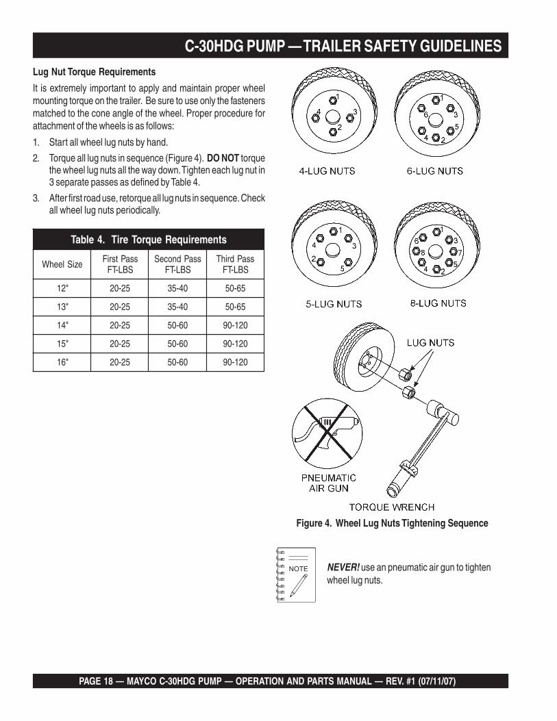
Lug Nut Torque Requirements
It is extremely important to apply and maintain proper wheelmounting torque on the trailer. Be sure to use only the fastenersmatched to the cone angle of the wheel. Proper procedure forattachment of the wheels is as follows:
1. Start all wheel lug nuts by hand.
2. Torque all lug nuts in sequence (Figure 4). DO NOT torquethe wheel lug nuts all the way down. Tighten each lug nut in3 separate passes as defined by Table 4.
3. After first road use, retorque all lug nuts in sequence. Checkall wheel lug nuts periodically.
C-30HDG PUMP — TRAILER SAFETY GUIDELINES
NEVER! use an pneumatic air gun to tightenwheel lug nuts.
Figure 4. Wheel Lug Nuts Tightening Sequence
stnemeriuqeReuqroTeriT.4elbaT
eziSleehW ssaPtsriFSBL-TF
ssaPdnoceSSBL-TF
ssaPdrihTSBL-TF
"21 52-02 04-53 56-05
"31 52-02 04-53 56-05
"41 52-02 06-05 021-09
"51 52-02 06-05 021-09
"61 52-02 06-05 021-09

MAYCO C-30HDG PUMP — OPERATION AND PARTS MANUAL — REV. #1 (07/11/07) — PAGE 19
NOTE PAGE

PAGE 20 — MAYCO C-30HDG PUMP — OPERATION AND PARTS MANUAL — REV. #1 (07/11/07)
C-30HDG PUMP — OPERATION AND SAFETY DECALS
Figure 5. Operation and Safety Decals
Figure 5 display's the operation and safety decals as they appear on the concrete pump, should any of these decals becomedamaged or unreadable, contact the Multiquip Parts Department for a replacement set.

MAYCO C-30HDG PUMP — OPERATION AND PARTS MANUAL — REV. #1 (07/11/07) — PAGE 21
C-30HDG PUMP — IMPORTANT HAND SIGNALS
Figure 6. Operation Hand Signals
Figure 6 display's the basic hand signals commonly used in concrete pumping operations.

PAGE 22 — MAYCO C-30HDG PUMP — OPERATION AND PARTS MANUAL — REV. #1 (07/11/07)
C-30HDG PUMP — PUMP COMPONENTS
Figure 7. Major Pump Components

MAYCO C-30HDG PUMP — OPERATION AND PARTS MANUAL — REV. #1 (07/11/07) — PAGE 23
C-30HDG PUMP — PUMP COMPONENTSFigure 7 illustrates the location of the major components for theC-30HDG Concrete Pump. The function of each component isdescribed below:
1. Discharge Cone – Connect 3" elbow to this dischargeport, then connect 3" x 2" reducer to elbow.
2. Discharge Cone Safety Latch – When towing of the pumpis required, ALWAYS secure the discharge cone to latchlocated on the manifold.
3. Rear Running Lights – ALWAYS check and make sureboth the right and left running lights are functioning correctlybefore towing the pump.
4. Hopper – Concrete from a Redi-Mix truck is poured intothis hopper. The hopper can hold 6.0 cu. ft of concrete.NEVER put hands or any other parts of you body into thehopper.
5. Safety Grill – The safety grill should be locked at all timeswhen the pump is being towed. Under normal workingconditions, raise and place the safety grill on the supporthooks which are located on splash guard.
6. Compartment Hood – NEVER operate the pump with thehood removed. Installed on the pump frame is a safety inter-lock device which prevents the engine from starting if thehood is removed or in the up position (open).
7. Hood Fastener – When the hood is in the down position,secure the rubber latch to this fastener.
8. Hood Lift Handle – Grip this handle, pull upward thenback to raise the compartment hood.
9. Control Box – Contains the mechanical and electricalcomponents required to run the pump. Below is a list ofthose components:
■ Throttle Control Switch■ Pumping Control■ Check Engine Indicator■ Hood Open Indicator■ Engine Hour Meter■ Ignition Switch■ Remote Connector
12. Tow End Jack Stand – Use this jack stand to level andsupport the pump.
13. Tow Hitch Coupler – Requires a 2-inch ball hitch or a 3-inch pintle. Capable of towing 5,000 lbs.
14. Safety Chain – ALWAYS attach safety chain to the towingvehicle. NEVER! tow the pump with the safety chainunattached.
15. Engine Safety Device – This device will return the enginespeed to idle if the compartment hood is in the UP position.The compartment hood must be in the DOWN position forthe pump to operate at high rpm's.
16. Grease Port Console – This console allows for the remotelubrication of components on the pump.
17. Access Door – There are four access doors on the pump.Remove these door to gain access to drive and pistonassemblies when maintenance is required.
18. Drive Chain – Keep this chain properly lubricated andaligned at all times. Lubricate this chain as specified in themaintenance section of this maintenance.
19. Rubber Latch – Secure this rubber latch to the hoodfastener whenever the pump is in use or being towed.
20. Tires Ply– The tire ply (layers) number is rated in letters;This trailer uses 4-ply tires.
21. Chock Blocks – Place these blocks (not included as partof your concrete pump package) under each trailer wheelto prevent rolling.
22. Pump End Jack Stand – Use this jack stand to level andsupport the pump.
23. Discharge Cone Release Lever – secures the dischargecone to the "Y" manifold; also relieves manifold pressure.
24. Documentation Box – Contains engine and pumpoperation, parts and maintenance information.
25. Lubrication Box – This box is empty when shipped fromthe factory. Please fill with 7 gallons ( 26.5 liters) of SAEmotor oil for first time use. Also check the dual clean-outpoint on bottom of lubrication box for a secure tight fit.
26. Overflow Bottle – Fill with coolant. Maintain coolant atproper level. See fluid level markings on side of bottle.
27. Cam Bearing – Felt ring must be peridically lubricatedapplying 4 or 5 drops of 30 wt. motor oil until the felt ring ismoist.
10. Radiator/Cap – Fill with a water/anti-freeze type solutionas recommended in the maintenance section of this manual.ALWAYS make sure that the radiator is filled to the properoperating level before starting the engine.
11. Fuel Tank/Cap – Fill with unleaded fuel. Fuel tank (cell)holds approximately 11 gallons (42 liters). DO NOT top offfuel. Wipe up any spilled fuel immediately
PAGE 24 — MAYCO C-30HDG PUMP — OPERATION AND PARTS MANUAL — REV. #1 (07/11/07)
C-30HDG PUMP — CONTROL BOX COMPONENTS
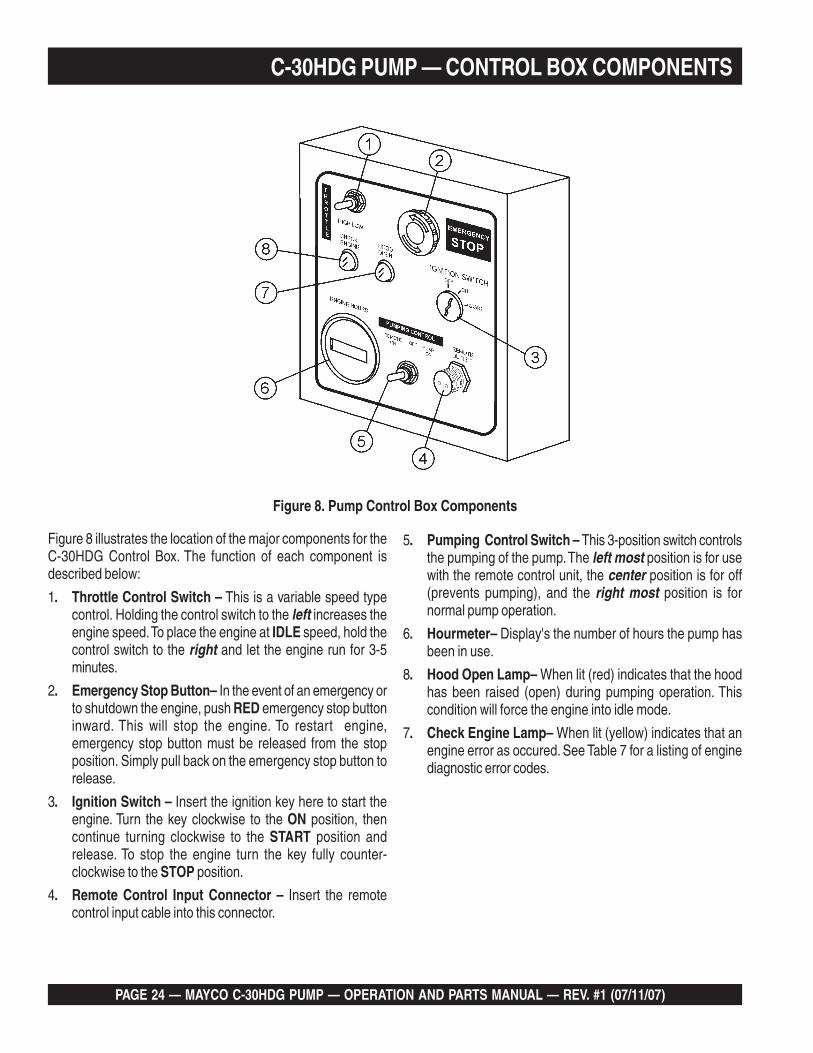
Figure 8. Pump Control Box Components
Figure 8 illustrates the location of the major components for theC-30HDG Control Box. The function of each component isdescribed below:
1. Throttle Control Switch – This is a variable speed typecontrol. Holding the control switch to the left increases theengine speed. To place the engine at IDLE speed, hold thecontrol switch to the right and let the engine run for 3-5minutes.
2. Emergency Stop Button– In the event of an emergency orto shutdown the engine, push RED emergency stop buttoninward. This will stop the engine. To restart engine,emergency stop button must be released from the stopposition. Simply pull back on the emergency stop button torelease.
3. Ignition Switch – Insert the ignition key here to start theengine. Turn the key clockwise to the ON position, thencontinue turning clockwise to the START position andrelease. To stop the engine turn the key fully counter-clockwise to the STOP position.
4. Remote Control Input Connector – Insert the remotecontrol input cable into this connector.
5. Pumping Control Switch – This 3-position switch controlsthe pumping of the pump. The left most position is for usewith the remote control unit, the center position is for off(prevents pumping), and the right most position is fornormal pump operation.
6. Hourmeter– Display's the number of hours the pump hasbeen in use.
8. Hood Open Lamp– When lit (red) indicates that the hoodhas been raised (open) during pumping operation. Thiscondition will force the engine into idle mode.
7. Check Engine Lamp– When lit (yellow) indicates that anengine error as occured. See Table 7 for a listing of enginediagnostic error codes.

MAYCO C-30HDG PUMP — OPERATION AND PARTS MANUAL — REV. #1 (07/11/07) — PAGE 25
C-30HDG PUMP — ENGINE COMPONENTS
Figure 9. Zenith 416 Basic Engine Components
Figure 9 illustrates the location of the basic components for theZenith 416, 1.6 liter gasoline engine..The function of eachcomponent is described below:
1. Air Filter – Prevents dirt and other debris from entering thefuel system. Remove wing-nut on top of air filter cannister togain access to filter element. Replace with onlymanufactures recommended type air filter.
2. Fuse Connector – Contains fuses for electrical system.replace with only recommended type fuses.
3. Oil Filler Port Cap – Remove this cap to add engine oil tothe crankcase. Fill with recommended type oil as specifiedin the maintenance section of this manual
4. Spark Plug – Provides spark to the ignition system. Setspark plug gap to 0.6 - 0.7 mm (0.028 - 0.031 inch). Cleanspark plug once a week
5. Dipstick – Remove this dipstick to determine if engine oilis low. Maintain oil level at the "H" marking on the dipstick.NEVER run engine with low oil.
6. Alternator – Provides power to the electrical system.Replace with only manufactures recommended typealternator.
7. Oil Filter – Replace this oil filter as recommended in themaintenance section of this manual.
8. Fan V-Belt – ALWAYS make sure that V-belt is properlytensioned. A loose or defective V-belt can adversely affectthe performance of the pump.
9. Crankcase Drain Plug – Remove this plug to drain engineoil from the crankcase. Replace with recommended engineoil as specified in the maintenance section of this manual.
10. Cooling Fan Blades – Make sure that the blades of thecooling fan are not bent or broken. A damaged fan bladecan cause the engine to run hot and overheat.
11. Control Relays – Includes a main relay, fuel pump relayand starter relay. Replace with only recommended typerelays.
12. Starter Motor/Solenoid – NEVER allow concrete or anyforeign debris to come in contact with the starter motor/solenoid.
13. Fuel Filter/Fuel Pump/Fuel Regulator – Replace or cleanthe fuel filter, fuel pump or fuel regulator as specified in themaintenance section of this manual.
Operating the engine without an air filter, with adamaged air filter, or a filter in need of replacementwill allow dirt to enter the engine, causing rapidengine wear.

PAGE 26 — MAYCO C-30HDG PUMP — OPERATION AND PARTS MANUAL — REV. #1 (07/11/07)
C-30HDG PUMP — GENERAL INFORMATIONThe following operating principles and operating suggestionsshould prove helpful in the successful operation of your concretepump. Your new “small line” concrete pump has been designedto give you many years of service when operated properly. Astudy of the following paragraphs is important to the successfuloperation of your new Direct-flow Concrete Placer.
All concrete pumps require a high level of operator skill andmore frequent service than most of the other constructionequipment. The highly abrasive nature of concrete under pressuremakes it extremely important that expendable wear componentsbe inspected at regular intervals between jobs to prevent havingto replace these items during a pour.
Experience has proved that inconsistency of batched concretemixes and frequent moving of the line requires the operator to bereadily available at all times during pumping to stop the pumpand prevent abuse to the unit which may occur if unexpectedblockages develop.
As a general rule, the use of approximately six sacks of cement,70% washed concrete sand and 30% #4 pea gravel per yard ofconcrete will result in a pumpable mix. The ideal nature of sandand rock in certain areas may permit you to increase thepercentage of rock or adjust the mix considerably to meet the jobrequirements. When possible, you may experiment with variousmixes in your area to determine the degree of versatility of theDirect-flow Pump.
Uniform gradation of the washed concrete sand and the 1/2”minus aggregate along with sufficient cement content and waterare important to a successful pump operation.
A recommended pumpable mix design would be 70% sand and30% aggregate-cement content to be a minimum of 6 sacks.(564 lbs.)
Sample Design Mix - 3000 Psi 3/8 in. Slump 4- 5 in.
Type II Cement 6.49 sack/cu. yd 611 lbs.
Sand Sat. Surf. Dry 2000 lbs.
#4 Gravel Sat. Surf. Dry 864 lbs.
#3 Gravel Sat. Surf. Dry 0 lbs.
Water 48 Gallons 400 lbs.
Total Weight 3,906 lbs
Admixture WRDA-79 26 oz.
Water 7.40 gal/sack
Test laboratory data has proven in many areas that the abovemix guidelines have produced concrete rated at 3000 psi (28day test) and upwards of 5000 psi with an increase in cement.
In some areas where the gradation of sand and rock is ideal andsufficient cement is used along with admixtures, the Mayco smallline concrete pump will handle up to a 50-50 ratio of sand androck.
When the mix is designed for wet gunning applications, it isnormal to increase the cement (up to 7.5 or 8 sacks) and changethe sand to rock ratio to 85% sand and 15% rock.
The Mayco concrete pump will valve efficiently when usingcellular-foam concrete mixes upwards of 70 lbs. per cubic footwet density. (Below 70 lbs. materials (roof decks) the valvingbecomes inefficient.)
Your local sand and rock engineers will give youthe S.S.D. weights of sand and rock required inyour local area which will yield one cubic yard perthe above recommendation.
If jamming conditions in the pump or hose occurfor any reason at all, do not attempt to use morepower to correct the condition.
Determine the cause of jamming, correct it and resume pumping.Trying to force material through under jammed conditions mayresult in damage to the drive system, thus voiding any warrantyservices.
Pump Mix Guidelines
When ordering concrete, be certain to advise the concrete supplierthat you require a “pump mix”. The Direct-flow manifold willpump a wide variety of materials, but certain basic principlesmust be followed to assure successful pumping, as follows:
Generally speaking, the washed concrete sand and #4 aggregate(pea gravel) should conform to A.S.T.M. standards in regard tosieve analysis. Sands in some areas are washed clean of the#100 and #200 mesh fines, which results in separation andjamming in the manifold while pumping under pressure.
If this condition develops, check with your concrete suppliersengineers and get their recommendations for supplementingthe lack of the fines. The use of locally accepted ad-mixes maybe required. (For example, Pozzolith, Bentonite Clay, Plastiments,etc.) When properly prescribed, additives form the plastic pastesometimes necessary to hold the cement and aggregate together.

MAYCO C-30HDG PUMP — OPERATION AND PARTS MANUAL — REV. #1 (07/11/07) — PAGE 27
C-30HDG PUMP — HOW IT WORKSThe C-30HDG concrete pump has one main pumping pistonwhich is valved by means of two ball checks. (A inlet, and Boutlet.)
The secondary piston is used as a compensator piston to smoothout the pulsations of a single piston action. Note: The compensatorwill not start operating until material is pumped into the line andback pressure develops.
The compensator spring, which is installed on the compensatorpiston rod, deflects with each piston stroke. This “spring cushion”,in conjunction with the cam profile, produces and uninterruptedsmooth flow of material under average pumping conditions.
The pumping cylinder (Figure 10) retracts drawing the materialpast the ball (A) and filling the cylinder. The compensator pistonis pumping the material out to the nozzle and causing ball (B) toseat preventing the material from returning to the pumping cylinderintake.
An automatic, centrifugal clutch is installed to engage anddisengage the pumping action without stopping or starting theengine. The centrifugal clutch is set at 1100 R.P.M. The engineidle speed is approximately 875 R.P.M.; therefore, the clutch iscompletely disengaged at idle. The throttle settings while pumpingshould always maintain an engine R.P.M. high enough to preventthe clutch from slipping and burning the clutch lining.
The return spring which is installed on the rocker arm, is installedto eliminate shock and stress between the cam roller and thecam weldment when the pump is in operation. If the return springis removed or replaced for any reason, maintain the backingplate dimension of 3” as shown on Figure 3, to produce theproper pre-loading of the spring for a smooth performance.
Figure 10. Pumping Cylinder
PAGE 28 — MAYCO C-30HDG PUMP — OPERATION AND PARTS MANUAL — REV. #1 (07/11/07)
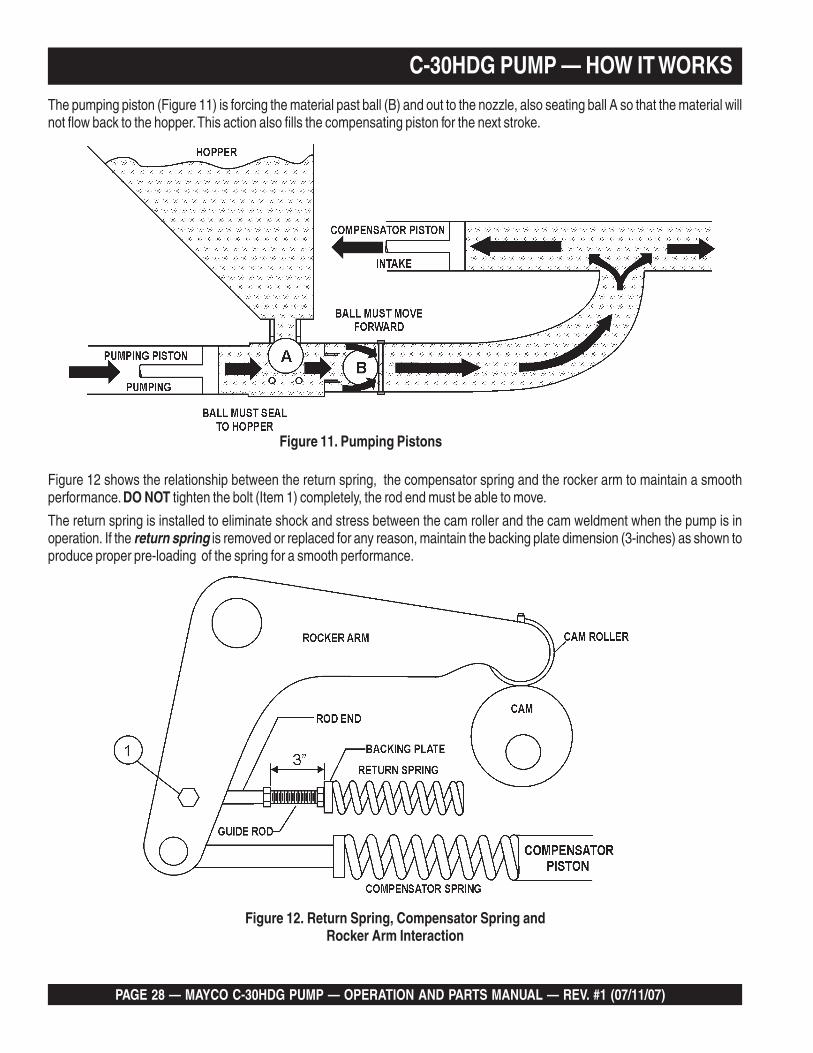
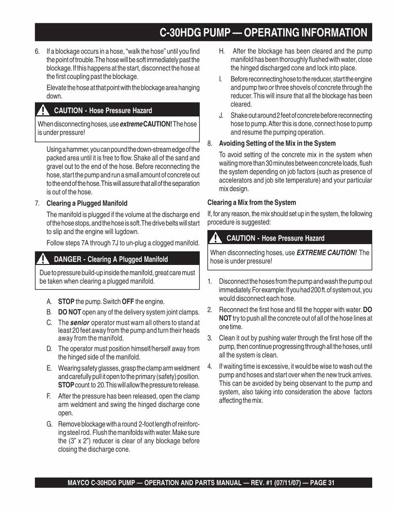
Figure 12 shows the relationship between the return spring, the compensator spring and the rocker arm to maintain a smoothperformance. DO NOT tighten the bolt (Item 1) completely, the rod end must be able to move.
The return spring is installed to eliminate shock and stress between the cam roller and the cam weldment when the pump is inoperation. If the return spring is removed or replaced for any reason, maintain the backing plate dimension (3-inches) as shown toproduce proper pre-loading of the spring for a smooth performance.
The pumping piston (Figure 11) is forcing the material past ball (B) and out to the nozzle, also seating ball A so that the material willnot flow back to the hopper. This action also fills the compensating piston for the next stroke.
Figure 11. Pumping Pistons
Figure 12. Return Spring, Compensator Spring andRocker Arm Interaction
C-30HDG PUMP — HOW IT WORKS

MAYCO C-30HDG PUMP — OPERATION AND PARTS MANUAL — REV. #1 (07/11/07) — PAGE 29
C-30HDG PUMP — OPERATING INFORMATION
OPERATING SUGGESTIONS
1. A well-planned location of the pump and routing of the hosebefore starting a pour may save subsequent moves through-out the job.
2. Before concrete is discharged into the hopper, it is suggestedthat 3 to 4 gallons of water be sprayed into the hopper,followed by approximately 5 gallons of a creamy cement andwater slurry (1/2 bag of cement to 5 gallons of water). Thisprocedure lubricates the hose and prevents separation andblockages in the hose.
Getting the concrete to flow through the hose at thestart of the pumping cycle can be one of the mostcritical operations of the pour. (Manually operatethe throttle when starting, NOT remotely)
If hoses or lines are blocked for any reason, or if the lines arekinked when starting up or during the pumping cycle, thepump pressure could straighten out the kink or force out theblockage. This rapid surge of material could cause the lines towhip or move in a manner that could cause injury to personnel.
Inspect the lines at all times to prevent the aboveconditions
3. It is important that once the slurry procedure is completed,and you have started concrete flowing through the hose, donot stop the pour until all the slurry is pumped out and theconcrete has reached the end of the hose. The only time tostop the pump at the start is if a blockage occurs.
4. When the pump is stopped for any reason during a pour; e.g.,moving hose, waiting for redi-mix truck, the following sugges-tions are offered:
A. Leave the hopper full of concrete at the time of shutdown.It is important not to let the redi-mix driver wash too muchwater into the hopper, as this could cause separation ofthe concrete in the hopper.
B. If the shutdown period exceeds 2 to 3 minutes, turn offthe engine so the vibration does not separate the mix inthe hopper which can cause a blockage in the manifoldwhen the pump is started.
C. If it is necessary to wait 10 minutes or more for anotherload of concrete, it is wise to start the pump and pump 6or 8 strokes every 5 minutes to prevent setting of the mixin the system. If waiting time is excessive, it would be wiseto wash out the pump and hoses and start over when thenew truck arrives.
D. When pumping stiff mixes and there is waiting timebetween redi-mix trucks, it is advisable to add somewater to the last hopper of material and “hand mix” toensure an easier start with the following load.
E. When the pumping job requires a stiffer mix, the follow-ing method is suggested for starting: Take a water hosewith a nozzle on it and apply water with a fine spray to theconcrete as it comes down the redi-mix chute into thepump hopper after the slurry procedure is completed andyou are ready to start pumping.
Using this procedure will make it easier to pump throughthe clean hose. Note: Once the concrete has reached theend of the hose, do not apply any more water in thismanner as this procedure is used on the start only.
F. Hose sizing is very important: We strongly recommendon harsh mixes, vertical pushes, stiff concrete, shotcrete,long pushes, that a 2 -1/2” line be used as far as possible.The advantages of using the 2 -1/2” line are improvedpumpability, less pumping pressure and less wear on thepump.
5. Following the pump operation, proper wash out of all mate-rials or “build-up” within the pump manifold and hoses willprevent problems when starting the next job.
6. A thorough inspection of the drive components and greasingof all bearings after each job will ensure adequate lubricationand service to the pump which is normally operating in wet,gritty conditions.
Over-greasing any bearing on your Mayco pumpwill not damage the bearing.
WARNING - Hose Blockage Hazard

PAGE 30 — MAYCO C-30HDG PUMP — OPERATION AND PARTS MANUAL — REV. #1 (07/11/07)
C-30HDG PUMP — OPERATING INFORMATION
Pumping Tips
1. The effects of heat and excessive time on concrete: Hotconcrete, commonly referred to as a hot load, is concrete thathas been in the redi-mix truck in excess of 2 to 3 hours. On ahot day, this amount of time is even less. A brief explanationof why heat and time affect concrete:
Concrete starts setting by drying up through a chemicalreaction. The catalyst to this reaction is heat. When pumpinga hot load, it is important to remember that when you have tostop pumping for any reason, add water to the concrete in thehopper and hand mix and move concrete in the hose every5 minutes. If the shut down time becomes too long, wash outimmediately.
All admixtures will be shown on the redi-mix con-crete ticket. Before starting the pumping job, ask thedriver of the redi-mix truck to see the concrete ticketand note the admixtures that exist and take theproper action.
3. When pumping long distance or pumping stiff mixes, you canexpect a drop in volume compared to shorter lines and wettermixes due to the change in valve efficiency or cavitation.
4. Leaking manifold seals or hose coupling gaskets which leakwater can cause separation and subsequent jamming at thatpoint.
5. Damaged hoses with internal restrictions can cause block-ages.
If you repeatedly pull the throttle all the way out and try to forceyour pump to push through blockages due to separation ofmaterial in the hose or manifold, you will soon havebreakdowns and costly repairs which are not covered underwarranty.
If a blockage occurs, find where it is and clear it before furtherpumping. DO NOT increase the engine speed to clear theblockage. Increasing the engine speed will only compoundthe problem.
WARNING - Hose Blockage Hazard
It will be necessary at times to move your pump from one jobsite location to another. Before moving the pump, make sure topump the remaining concrete out of the hopper. Moving thepump with a full hopper of concrete can cause severe damageor breakage of the axle and axle springs, excess strain andpressure on the hub and bearing assembly.
WARNING - Moving The Pump On The Job Site
New Pumps
All new pumps are “water pressure tested ” at the factory beforeshipment. This procedure permits a thorough inspection of theentire drive system and valving under simulated full load condi-tions.
The pump owner can do the same by attaching an adaptor coupleto the end of the discharge cone; e.g., the use of a standard 2 in.pipe cap with a 3/8 in. hole drilled in the center, screwed on to theend of the hinged cone or reducer at the pump.
Fill the hopper with water after making sure that all sand and rockhave been removed from the manifold. Operate the pump at fullthrottle and the 3/8 in. diameter hole restriction will create sufficientback-pressure to make a thorough inspection of all moving parts.
2. ADMIXTURES
Remixtures that are designed into the concrete mix by theredi-mix company or an architectural engineering company.This section lists common admixtures and a brief explanationof their functions:
A. Pozzolith 300 – or the equivalent acts as a waterretarder and a lubricant. On a lean mix, long pushes, stiffmixes, and vertical pushes, Pozzolith 300R helpspumpability.
B. MBVR – air entraining, acts as a lubricant.
C. Calcium Chloride – commonly referred to as C.C., isused as an accelerator. When pumping a load withcalcium chloride, it is recommended that you wash outif the waiting time between delivery trucks becomes toolong.
D. Super Plasticizers – acts as an accelerator. Theconcrete will look very wet after the super plasticizer isadded, but will begin to set up very fast. Wash outimmediately if you do not have a truck waiting. Superplasticizers are used mainly on commercial jobs.
E. Red Label – acts as a water retarder and an accelerator.Red label will be used mainly on commercial jobs.
F. Fly Ash – is used to help increase the strength of theconcrete and decrease the cement content per yard. Thisis one of the most common admixtures used.
MAYCO C-30HDG PUMP — OPERATION AND PARTS MANUAL — REV. #1 (07/11/07) — PAGE 31
6. If a blockage occurs in a hose, “walk the hose” until you findthe point of trouble. The hose will be soft immediately past theblockage. If this happens at the start, disconnect the hose atthe first coupling past the blockage.
Elevate the hose at that point with the blockage area hangingdown.
C-30HDG PUMP — OPERATING INFORMATION
A. STOP the pump. Switch OFF the engine.B. DO NOT open any of the delivery system joint clamps.C. The senior operator must warn all others to stand at
least 20 feet away from the pump and turn their headsaway from the manifold.
D. The operator must position himself/herself away fromthe hinged side of the manifold.
E. Wearing safety glasses, grasp the clamp arm weldmentand carefully pull it open to the primary (safety) position.STOP count to 20. This will allow the pressure to release.
F. After the pressure has been released, open the clamparm weldment and swing the hinged discharge coneopen.
G. Remove blockage with a round 2-foot length of reinforc-ing steel rod. Flush the manifolds with water. Make surethe (3” x 2”) reducer is clear of any blockage beforeclosing the discharge cone.
H. After the blockage has been cleared and the pumpmanifold has been thoroughly flushed with water, closethe hinged discharged cone and lock into place.
I. Before reconnecting hose to the reducer, start the engineand pump two or three shovels of concrete through thereducer. This will insure that all the blockage has beencleared.
J. Shake out around 2 feet of concrete before reconnectinghose to pump. After this is done, connect hose to pumpand resume the pumping operation.
8. Avoiding Setting of the Mix in the System
To avoid setting of the concrete mix in the system whenwaiting more than 30 minutes between concrete loads, flushthe system depending on job factors (such as presence ofaccelerators and job site temperature) and your particularmix design.
When disconnecting hoses, use EXTREME CAUTION! Thehose is under pressure!
1. Disconnect the hoses from the pump and wash the pump outimmediately. For example: If you had 200 ft. of system out, youwould disconnect each hose.
2. Reconnect the first hose and fill the hopper with water. DONOT try to push all the concrete out of all of the hose lines atone time.
3. Clean it out by pushing water through the first hose off thepump, then continue progressing through all the hoses, untilall the system is clean.
4. If waiting time is excessive, it would be wise to wash out thepump and hoses and start over when the new truck arrives.This can be avoided by being observant to the pump andsystem, also taking into consideration the above factorsaffecting the mix.
Due to pressure build-up inside the manifold, great care mustbe taken when clearing a plugged manifold.
DANGER - Clearing A Plugged Manifold
CAUTION - Hose Pressure Hazard
Using a hammer, you can pound the down-stream edge of thepacked area until it is free to flow. Shake all of the sand andgravel out to the end of the hose. Before reconnecting thehose, start the pump and run a small amount of concrete outto the end of the hose. This will assure that all of the separationis out of the hose.
7. Clearing a Plugged Manifold
The manifold is plugged if the volume at the discharge endof the hose stops, and the hose is soft. The drive belts will startto slip and the engine will lugdown.
Follow steps 7A through 7J to un-plug a clogged manifold.
When disconnecting hoses, use extreme CAUTION! The hoseis under pressure!
CAUTION - Hose Pressure Hazard
Clearing a Mix from the System
If, for any reason, the mix should set up in the system, the followingprocedure is suggested:

PAGE 32 — MAYCO C-30HDG PUMP — OPERATION AND PARTS MANUAL — REV. #1 (07/11/07)
Down-Hill Pumping
Downhill pumping can be difficult on some jobs. It is suggested thata sponge 2”x 4”x 6” be placed in the hose before the start ofpumping. Wet the sponge before placing it in the hose. Referencethe Operating Suggestions at the start of this section for slurryprocedures.
The reason for using the wet sponge is to keep the slurry fromrunning too far ahead of the concrete and so reducing thepossibility of separation. When the pump is stopped, the materialcan flow slowly down, due to gravity, and cause the hose tocollapse.
When pumping is resumed, you can expect a blockage at the pointof hose collapse. To prevent this from happening, the hose can be“kinked off” at the discharge end when the pump is stopped toprevent the gravity flow of the material in the hose.
The use of stiffer mixes when pumping down-hill will decreasegravity flow of the material in the hose and will assure a smootheroperation between the cam roller bearing and cam plate. As withany job, make sure that the hose and the couplings are in goodworkable shape.
It is strongly recommended that steel pipe be usedon ALL vertical pumping for safety and conve-nience.
Valve Seats
If the volume at the end of hose starts to decrease gradually andeventually almost stops, it is quite likely that the valve seats havehad excessive wear and need replacement. Once they havereached a certain wear point, they may “channel out” rapidly andmaterial will reciprocate past the ball on each stroke.
The hollow steel ball should be replaced when it starts to showdents or appears to be badly worn. Sand and aggregate materialsin some areas are extremely sharp and hard and therefore highlyabrasive. Under these conditions when pumping stiff mixes, or tohigh elevations which cause line pressures, it will be noted thatvalve components may have short wear life.
If this condition exists, it is advisable to remove the manifold only,and inspect the lower seat at the end of each day. If it appears thatthe seat is beginning to “channel out", replace before starting thenext day’s pour.
The upper valve seat can be inspected after each washout byrunning your finger around lower edge of seat where the ballmakes contact. You can reach this from the inside of the hopper. Besure that the engine is turned off.
C-30HDG PUMP — OPERATING INFORMATION
Vertical Pumping
When pumping vertically up the side of a building, above 40 feet,we would recommend the installation of steel pipe securelyfastened at intervals as necessary to support the pipe. Ninetydegree, long radius pipe sweeps should be installed at the top andbottom of the steel line.
Use a 25 ft. hose, or short section, off the pump; and for the balanceof the horizontal distance to the vertical line, use steel pipe. Thistype of installation has been satisfactory on many jobs beingpumped in excess of 100 feet high. Line pressures are always lessusing steel pipe as compared to hose.
When pumping vertically using all hose, it is recommended notto go higher than 50 feet with hose. The hose should be tied off atintervals of 10 feet, if possible. Special attention should be givenwhen tieing the hose off at the top as the hose will have a tendencyto stretch when filled with concrete. This will increase the possi-bility of a blockage at the point where the hose is tied off. To avoidthis, a long radius of 90 degree elbow is recommended. Thesuggested place to tie off is on the hose, under the clamp.
Pulsation
A slight pulsation of the hose will always be noticeable near thepump. Excessive pulsation of the hose near the pump is normallydue to higher than average line pressures caused by stiff, harshmixes, or extremely long pumping distances.
The use of 2 -1/2” I.D. hose in these extreme cases reduces linepressures or the addition of slight amounts of water to the mix, ifpermissible, will permit easier pumping. The use of certain pump-ing admixtures may help.
If excessive pulsation exists in the hose, it is advisable to useburlap or some means of wear protection under the hose at pointswhere the hose may wear through the outer cover; e.g. over forms,steel or sharp curbs.

MAYCO C-30HDG PUMP — OPERATION AND PARTS MANUAL — REV. #1 (07/11/07) — PAGE 33
C-30HDG PUMP — OPERATING INFORMATIONCam Roller
If the cam roller does not ride on the cam profile smoothly, it maybe caused by insufficient line back-pressure; e.g., a wet mix withonly 50 feet of hose. Add more hose as necessary. It can also becaused by cavitation or the passing of over-sized aggregatesthrough the valving, causing it to skip.
Snap-Joint
When using Snap-Joint couplings with gaskets to join hose, seethat they are washed clean after each job. Keeping the hose endsclean (heavy duty) is very important for the best job setup. A thincoat of grease on the rubber gasket or dipping both coupling andgasket in water before coupling the hose will make for easierinstallation.

PAGE 34 — MAYCO C-30HDG PUMP — OPERATION AND PARTS MANUAL — REV. #1 (07/11/07)
C-30HDG PUMP — INSPECTION
Figure 13. Engine Oil Dipstick (Removal)
3. Check the engine oil level as shown on the dipstick(Figure 14).
4. If the engine oil level is low, add oil through the engine oil fillerhole (Figure 15) with the recommended oil type (Table 3).Maximum oil capacity is 3.9 quarts (3.7 liters).
Figure 14. Engine Oil Dipstick
Figure 15. Engine Oil Filler Hole
Reference manufacturer engine manual forspecific servicing instructions.
Engine Oil Check
1. To check the engine oil level, place the pump on securelevel ground with the engine stopped.
2. Remove the dipstick from its holder (Figure 13) and wipe itclean.
CAUTION - General Saftey Guidelines
ALWAYS wear approved eye and hearingprotection before operating the pump .
NEVER operate the pumps's engine with theengine hood removed. The possibility existsof hands, long hair, and clothingbecoming entangled with the V-belt, causinginjury and bodily harm.
NEVER place hands or feet inside the hopper. ALWAYS makewhile the engine is running. ALWAYS shut-down the enginebefore performing any kind of maintenance service on thepump.
NEVER operate the pump in a confinedarea or enclosed area structure that doesnot provide ample free flow of air.
Before Starting
1. Read safety instructions at the beginning ofthis manual.
2. Removing any dirt and dust that might have accumulatedaround the engine cooling air inlet, fuel injection system.
3. Check the air filter for dirt and dust. If air filter is dirty, replaceair filter with a new one as required.
4. Check fuel injection system for external dirt and dust. Cleanwith dry compressed air.
5. Check fastening nuts and bolts for tightness.
6. Connect Battery
7. Make sure hopper is free of dirt and foreign debris (largeobjects over 2-inches)
8. Make sure radiator is filled with proper amount of anti-freezewater solution (50/50).
9. Make sure all hose lines are in good condition and areworking properly.

MAYCO C-30HDG PUMP — OPERATION AND PARTS MANUAL — REV. #1 (07/11/07) — PAGE 35
Gasoline Check
1. Remove the gasoline cap located on top of fuel tank.
2. Handle Fuel in a safety container. If the container does nothave a spout use a funnel.
3. Visually inspect to see if fuel level is low. If fuel is low,replenish with unleaded fuel. When refueling, be sure to usea strainer for filtration. DO NOT top-off fuel. Wipe up anyspilled fuel.
4. Pay attention to the fuel tank capacity when replenishing fuel.Refer to the fuel tank capacity listed in Table 5.
C-30HDG PUMP — INSPECTIONLubrication Box
The model C-30HDG model features a fully enclosedlubrication box, which utilizes the "SPLASH" method oflubrication.
Before using your new pump, 7 gallons of SAE 30 motor oil mustbe added directly into the lubrication box. Visually inspect the oilin the lubrication box by making sure the oil is at the correctoperating level as indicated by the dip stick (Figure 16).
Also reference the oil level decal (Figure 17) adjacent to thelubrication box.
Figure 16. Lubrication Box Dipstick
Figure 17. Lubrication Box Oil Caution Decal
EPYTLIO.5ELBAT
nosaeS erutarepmeT epyTliO
remmuS 52 o retaergdnaC 03-W01EAS
llaF/gnirpS 01 o 52otC oC 02/03-W01EAS
retniW 0o rewoLroC 01-W01EAS
Gasoline is extremely flammable, and itsvapors can cause an explosion if ignited.DO NOT start the engine near spilled fuelor combustible fluids. DO NOT fill the fueltank while the engine is running or hot.
DO NOT overfill tank, since spilled fuelcould ignite if it comes into contact with hot engine parts orsparks from the ignition system. Store fuel in approvedcontainers, in well-ventilated areas and away from sparks andflames. NEVER use fuel as a cleaning agent.
DO NOT smoke while refueling, motor fuels are highlyflammable and can be dangerous if mishandled.
WARNING - EXPLOSIVE FUEL
Make sure the pump is on a secure level surfacewhen checking the oil level inside the lubrication box.
CAUTION - Checking Lubrication Oil Levels
The oil level must be checked daily to ensure adequate oillevel and oil cleaniness.
PAGE 36 — MAYCO C-30HDG PUMP — OPERATION AND PARTS MANUAL — REV. #1 (07/11/07)
Starting
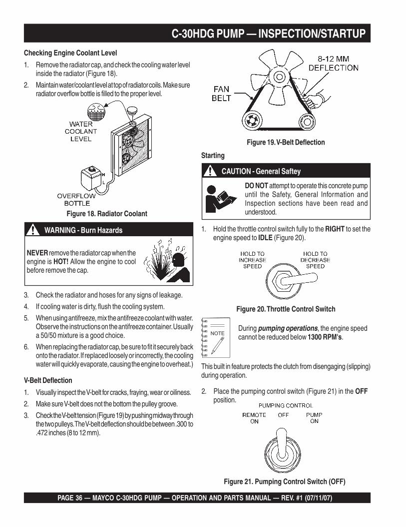
1. Hold the throttle control switch fully to the RIGHT to set theengine speed to IDLE (Figure 20).
Figure 20. Throttle Control Switch
2. Place the pumping control switch (Figure 21) in the OFFposition.
Figure 21. Pumping Control Switch (OFF)
During pumping operations, the engine speedcannot be reduced below 1300 RPM's.
CAUTION - General Saftey
DO NOT attempt to operate this concrete pumpuntil the Safety, General Information andInspection sections have been read andunderstood.
C-30HDG PUMP — INSPECTION/STARTUPChecking Engine Coolant Level
1. Remove the radiator cap, and check the cooling water levelinside the radiator (Figure 18).
2. Maintain water/coolant level at top of radiator coils. Make sureradiator overflow bottle is filled to the proper level.
Figure 18. Radiator Coolant
Figure 19. V-Belt Deflection
V-Belt Deflection
1. Visually inspect the V-belt for cracks, fraying, wear or oiliness.
2. Make sure V-belt does not the bottom the pulley groove.
3. Check the V-belt tension (Figure 19) by pushing midway throughthe two pulleys. The V-belt deflection should be between .300 to.472 inches (8 to 12 mm).
NEVER remove the radiator cap when theengine is HOT! Allow the engine to coolbefore remove the cap.
WARNING - Burn Hazards
3. Check the radiator and hoses for any signs of leakage.
4. If cooling water is dirty, flush the cooling system.
5. When using antifreeze, mix the antifreeze coolant with water.Observe the instructions on the antifreeze container. Usuallya 50/50 mixture is a good choice.
6. When replacing the radiator cap, be sure to fit it securely backonto the radiator. If replaced loosely or incorrectly, the coolingwater will quickly evaporate, causing the engine to overheat.) This built in feature protects the clutch from disengaging (slipping)
during operation.

MAYCO C-30HDG PUMP — OPERATION AND PARTS MANUAL — REV. #1 (07/11/07) — PAGE 37
C-30HDG PUMP — STARTUP/SHUTDOWN PROCEDURES
Figure 22. Ignition Switch
3. Insert the ignition key into the ignition switch (Figure 22), turnthe key to the ON position, then to the START position,release the key when the engine starts.
4. Let the engine run for 3-5 minutes before putting pump intooperational use. Push the choke knob in all the way.
5. Listen for any abnormal sounds. If any mechanical or electri-cal problems exists, STOP the engine and correct the problem.
6. To begin pumping concrete. Place the pumping controlswitch (Figure 23) in the ON position
System Shut-Down
1. Place the pumping control switch in the OFF position(Figure 21).
2. Let the engine run at idle speed for 3-5 minutes.
3. Turn the ignition key (Figure 22) to the OFF position.
4. Clean pump as referenced in the maintenance section of thismanual.
Remote Control Operation
1. Connect the hand-held remote control cable (Figure 24) tothe control box.
Figure 23. Pumping Control Switch (ON)
Figure 25. Pumping Control Switch (Remote)
3. To begin pumping, place the toggle switch on the hand-heldremote unit (Figure 24)in the pump ON position
Radio Remote Control Operation
The MAYCO C30HDG Concrete Pump has a remote controlfeature (Figure 26) that allows the pump to be radio controlledvia a receiver/transmitter technique.
Contact your MAYCO representative for further informationregarding radio control pumping capability.
2. On the control box, place the pumping control switch in theREMOTE ON position (Figure 25)
Figure 24. Handheld Remote Control Cable
Figure 26. Handheld RadioReceiver/Transmitter

PAGE 38 — MAYCO C-30HDG PUMP — OPERATION AND PARTS MANUAL — REV. #1 (07/11/07)
C-30HDG PUMP — MAINTENANCE (PUMP)
General Clean-up Procedure
1. Ensure that there is no blockage in the hose and line(Pumping Tips, step 8) or in the manifold (Pumping Tips,step 7). If a blockage exists, clear it to ensure properoperation the next time it is used. At the end of every pour,or during long delays during a pour, the pump and deliverysystem must be thoroughly cleaned by removing all con-crete material.
2. Proper wash out of all materials or build up within thepump manifold and hoses following the pumping opera-tion will prevent problems when starting the next job. Aftercompletion of the pour, pump the remaining concrete inthe hopper through the discharge line.
To avoid the possibility of separation during clean-up, do not pump the concrete below the inlet ball inthe hopper. It is best to leave approximately 3 to 4inches of concrete above the inlet ball.
3. Turn the pump engine off before filling the hopper with water.Engine vibration at idle may “separate” material in the hopper,causing jamming in manifold when pumping is resumed.
4. Fill hopper with water and resume pumping. The water willpush the concrete through the line. When the water runs clearat the end of the hose, disconnect lines and shake out all thesand and sediment so the lines will be clean for the next pour.
5. It is important that the hinged discharge cone on the pumpmanifold be opened and all remaining concrete (rock andsand) be thoroughly washed out. This must be done aftereach job to prevent concrete build up in the dischargemanifolds and 3” discharge elbow.
Preventive Maintenance
It is extremely important to maintain this pump due to thehighly abrasive nature of concrete material.
1. Inspect all drive components for loose or worn bolts.
2. Drive belt/chain should be checked to remove all slack. Referto adjustment procedure.
3. ALWAYS carry extra “O” rings.
4. Keep entire pump clean of concrete to prevent build-up.
5. ALWAYS grease every fitting daily. Use only premium gradegrease.
Over greasing will not damage pump.
MAYCO C-30HDG PUMP — OPERATION AND PARTS MANUAL — REV. #1 (07/11/07) — PAGE 39
C-30HDG PUMP — MAINTENANCE (PUMP)Lubrication Box
The C-30HDG model features a fully enclosed lubrication box,which utilizes the "SPLASH" method of lubrication.
Visually inspect the oil in the lubrication box (Figure 16) by makingsure the oil is at the correct operating level as indicated by thedip stick. Also reference the oil level decal (Figure 17) adjacentto the lubrication box.
Make sure the pump is on a secure level surfacewhen checking the oil level inside the lubricationbox.
Piston Cup Wear
The rubber piston cups are a natural wear component andwill require periodic replacement. The life of the rubber cupsdepends on many factors, proper oil level, oil cleanliness,abrasiveness of aggregrate being pumped and material slumpetc.
IMPORTANT! To ensure maximum cup life, the oillevel in the lubrication box must be maintained atthe proper level. In addition the lubrication box mustbe cleaned periodically.
As the rubber piston cups wear, fine cement particles willaccumulate in the bottom of the lubrication box. Once this cementpaste reaches 1-inch in height, it is recommended that thelubrication box be drained (flushed) and cleaned and the oilreplaced with new SAE 30 motor oil.
There are two clean-out ports located at thebottom of the lubrication box.
Any questions regarding the lubrication box clean-out procedure,contact the MAYCO Service Department.
The pump engine should be turned OFF, asexplained in General Clean Up Procedure.
After the sides of the hopper have been cleaned,add a small amount of water to the remainingconcrete in the hopper and hand mix.
2. Start the pump engine and pump the hopper all the way down.
3. Disconnect the hose from the pump. Fill the hopper with waterand pump the remaining concrete out of the pump.
4. Open the hinged discharge cone and thoroughly wash out allremaining concrete (sand-sediment) from the cone andpump manifolds. Close the discharge cone and lock in place.
5. Take a sponge (2”x 4”x 6”) and soak it with water. Take the hosethat is disconnected from the pump and shake out theconcrete so that about 2 feet of it is clear. Insert the sponge intothe hose.
6. Reconnect the hose to the pump. Fill the hopper with waterand resume pumping. Run the pump approximately halfthrottle. The sponge will be discharged at the end of the linefollowed by clear water. At this point, the pump and lines willbe completely clean and ready for the next job.
Repeat steps 1 through 6 a few times to ensurethat the hose lines are thoroughly cleaned.
Sponge Clean-out Procedure
This section will explain the recommended procedure for usinga sponge to clean out the hose lines.
CAUTION - Clearing The Pump
NEVER use muriatic acid to clear the pump. Acid will dissolvethe chrome finish on the pumping cylinder.
NEVER use compressed air to clean out the lines.
When using a clean-out hook to clean out the rear of the redi-mix truck, use a safety chain to secure the clean-out hook tosome solid part of the redi-mix truck to prevent the hook fromjumping off the redi-mix truck’s hopper. Run the pump at halfthrottle.
1. After completion of the pour, pump the remaining concrete inthe hopper through the discharge line. Using a shovel, cleanthe sides of the hopper.
CAUTION - Checking Lubrication Oil Levels
The oil level must be checked daily to ensure adequate oillevel and oil cleaniness.
PAGE 40 — MAYCO C-30HDG PUMP — OPERATION AND PARTS MANUAL — REV. #1 (07/11/07)
C-30HDG PUMP — MAINTENANCE (PUMP)
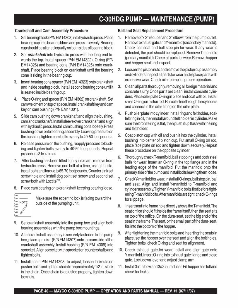
Crankshaft and Cam Assembly Procedure
1. Set bearing block (P/N EM14303) into hydraulic press. Placebearing cup into bearing block and press in evenly. Bearingcup should be aligned equally on both sides of bearing block.
2. Set crankshaft into hydraulic press with the long end to-wards the top. Install spacer (P/N EM14322), O-ring (P/NEM14326) and bearing cone (P/N EM14325) onto crank-shaft. Place bearing block on crankshaft until the bearingcone is riding in the bearing cup.
3. Insert bearing cone spacer (P/N EM14323) onto crankshaftand inside bearing block. Install second bearing cone until itis seated inside bearing cup.
4. Place O-ring and spacer (P/N EM14302) on crankshaft. Setcam weldment on top of spacer. Install crankshaft key and camkey on cam bushing (P/N EM14301).
5. Slide cam bushing down crankshaft and align the bushing,cam and crankshaft. Install sleeve over crankshaft and alignwith hydraulic press. Install cam bushing bolts loosely. Pressbushing down onto bearing assembly. Leaving pressure onthe bushing, tighten cam bolts evenly to 40-50 foot pounds.
6. Release pressure on the bushing, reapply pressure to bush-ing and tighten bolts evenly to 40-50 foot pounds. Repeatprocedure 3 to 4 times.
7. After bushing has been fitted tightly into cam, remove fromhydraulic press. Remove one bolt at a time, using Loctite,install bolts and torque to 65-70 foot pounds. Counter sink setscrew hole and install dog point set screw and second setscrew both with LoctiteTM.
8. Place cam bearing onto crankshaft keeping bearing loose.
Make sure the eccentric lock is facing toward theoutside of the pumping unit.
9. Set crankshaft assembly into the pump box and align bothbearing assemblies with the pump box mountings.
10. After crankshaft assembly is securely fastened to the pumpbox, place sprocket (P/N EM14307) onto the cam side of thecrankshaft assembly. Install bushing (P/N EM14309) intosprocket. Align sprocket with sprocket on countershafts andtighten bolts.
11. Install chain P/N EM14308. To adjust, loosen locknuts onpusher bolts and tighten chain to approximately 1/2 in. slackin the chain. Once chain is adjusted properly, tighten downlocknuts.
Ball and Seat Replacement Procedure
1. Remove 3”x 2” reducer and 3” elbow from the pump outlet.Remove exhaust gate and Y-manifold (secondary manifold).Check ball seat and ball stop pin for wear. If any wear isdetected, the part should be replaced. Remove T-manifold(primary manifold). Check all parts for wear. Remove hopperand hopper seat and inspect.
2. Loosen the piston nuts and remove the piston cup assemblyand cylinders. Inspect all parts for wear and replace parts withexcessive wear. Check oiler pump for proper operation.
3. Clean all parts thoroughly, removing all foreign material andconcrete slurry. Once parts are clean, install concrete cylin-ders. Place oiler plate O-ring in place and coat with oil. Installsmall O-ring on piston rod. Run oiler line through the cylindersand connect in the oiler fitting on the oiler plate.
4. Push oiler plate into cylinder. Install ring and felt holder, soakfelt ring in oil, then install around felt holder in cylinder. Makesure the bronze ring is flat, then push it up flush with the ringand felt holder.
5. Coat piston cup with oil and push it into the cylinder. Installbushing into center of piston cup. Put small O-ring on rod,place face plate on rod and tighten down securely. Repeatthese procedure on the opposite cylinder.
6. Thoroughly check T-manifold, ball stoppings and both steelballs for wear. Insert an O-ring in the top flange and in theleading edge of the manifold. Put the manifold onto theprimary side of the pump and install bolts leaving them loose.
7. Check Y-manifold for wear, install all O-rings, ball stop pin, balland seat. Align and install Y-manifold to T-manifold andcylinder assembly. Tighten Y-manifold bolts first before tight-ening T-manifold bolts. After manifolds are tight, check O-ringsfor slippage.
8. Insert seat into frame hole directly above the T-manifold. Theseat orifice should fit inside the frame itself, then the seat sitson top of the orifice. On the dura-seat, set the big end of theseat in the frame. The seat, or the small part of the dura-seat,fits into the bottom of the hopper.
9. After tightening the manifold bolts and inserting the seats inplace, set the hopper over the seat and align the bolt holes.Tighten bolts, check O-ring and seat for alignment.
10. Check exhaust gate for wear, install and align gate ontoY-manifold. Insert O-ring into exhaust gate flange and closegate. Lock down lever and adjust clamp arm.
11. Install 3 in. elbow and 3x 2 in. reducer. Fill hopper half full andcheck for leaks.

MAYCO C-30HDG PUMP — OPERATION AND PARTS MANUAL — REV. #1 (07/11/07) — PAGE 41
Clutch Lining Replacement(For P/N EM14320 Clutch Assembly Only)
The normal lining thickness measures 3/16 of an inch. If theclutch starts to slip or make an usual noise, it may be necessaryto replace the lining. Please note that the lining retaining rivetsshould not be exposed to the rotating weight.
The following procedure will assist you in replacing the lining.
1. Remove worn out lining and rivets. Check clutch springs andflyweights for wear.
2. Cut 1/8 in. off of each end of clutch lining. Slide lining intoplace. Insert one rivet into clutch lining hole. (Make sure rivetgoes from inside out.) Wedge a flathead screwdriver betweenclutch flyweight and rivet head.
3. Adjust screwdriver so that the rivet sticks out from the clutchhousing approximately 1/8 of an inch. With a flat punch, penthe ends on the rivet so that it locks in place with the clutchhousing. Repeat this procedure for all remaining clutch rivets.
The clutch lining is a normal maintenance itemand will require periodic replacement.
C-30HDG PUMP — MAINTENANCE (PUMP)

PAGE 42 — MAYCO C-30HDG PUMP — OPERATION AND PARTS MANUAL — REV. #1 (07/11/07)
Bearing Installation
1. Install the bearing components on the crankshaft making fullcontact with the back side of the crank disc as indicated thesymbol #. See Figure 24 below.
2. Install the bushing in the cam weldment and slide it onto thecrankshaft until contact is made with the bearing spacer.
3. Tighten the 3 allen head bolts “A” while exerting pressureon the bushing towards the bearing spacer.
It is important that the Bearing Assembly isinstalled properly.
C-30HDG PUMP — MAINTENANCE (PUMP)
Figure 24. Bearing/Cam Bushing Installation

MAYCO C-30HDG PUMP — OPERATION AND PARTS MANUAL — REV. #1 (07/11/07) — PAGE 43
C-30HDG PUMP — MAINTENANCE (PUMP)Detent Hole (3) Installation
1. After the bearing assembly has been is installed , remove thethree “dog type” allen head set screws (B) to allow detents tobe drilled. See Figure 25 below.
The detent holes will prevent the bushing fromsliding away from the bearing spacer when thepump is under load.
2. Use a 9/32” drill to “detent” half (minimum 1/8” deep). Then“chase” the threads with a 3/8-16 bottom tap and blow out thechips after drilling, to be certain that the “dog type” allen setscrews bottom in the detents to prevent the taper bushing fromsliding laterally.
3. If this procedure is not followed closely the heavy loadingof the bearing during pumping operation causes theTimken™ cone bearings to create lateral forces which willmove the taper bushing and allow the Timken™ conebearings to separate from the race and subsequently fail.
Figure 25. Detent Holes
4. Drill (detent) the shaft under the allen set screws “B” to preventthe bushing from the sliding away from the bearing spacerwhen the pump is under a load.
Position the ‘O’ ring on the O.D. of the bearingspacer during assembly to assure proper bearingadjustment.

PAGE 44 — MAYCO C-30HDG PUMP — OPERATION AND PARTS MANUAL — REV. #1 (07/11/07)
C-30HDG PUMP — MAINTENANCE (PUMP)
V-Belt And Drive Chain Adjustment
1. Loosen the pillow bearing bolts (Figure 26) only to the pointwhere the bolts will remain snug.
2 Unlock the two pusher bolt lock nuts.
3. Turn each pusher bolt clockwise an equal amount until thechain is to proper adjustment of approximately 3/8 to 1/2 in.slack in the chain. It is very important that the pulley side andthe chain side (pillow block bearings) are within 1/16” of anequal distance.
4. This distance can be checked by using a tape measure or astraight edge ruler, measuring from the inside of the pusherbolt bracket to the face of the pillow block bearing.
5. The drive chain should be adjusted regularly to remove allslack. Once all slack is removed, DO NOT over-adjust, as thiswill overload the shaft bearings. A slack chain on the crankdrive creates backlash and shock loads on the shafts andbearings which results in shorter wear/life of the drive com-ponents.
6. Lubricate the chain regularly. Note-it is advisable to carry aspare chain and master links for replacement in the field ifnecessary.
Figure 26. V-Belt and Drive Chain Adjustment
Prior to adjusting the chain, place the lobe of thecam in the down position. The chain should have83 rivets, Including one each, half-link and full link.
7. Drive belts should be regularly adjusted to prevent slippage.To adjust the belts, loosen the engine mounting bolts andmove the engine until there is a maximum 3/4 in. deflectionin the belts, retighten the engine mounting bolts.
8. Frequent inspections should be made on all drive compo-nents to make certain that all bolts and nuts remain tight.

MAYCO C-30HDG PUMP — OPERATION AND PARTS MANUAL — REV. #1 (07/11/07) — PAGE 45
C-30HDG PUMP — MAINTENANCE (PUMP)Roller Chain Application
A properly selected, installed and maintained drive chain(Figure 27) is an extremely versatile means of power transmission.It is possible, however, to greatly reduce a chain’s life and eveninduce failure if the chain is abused through improper installation,operating or maintenance procedures. In certain applications,failure can lead to personal injury or property damage.
Figure 28. Shaft and Drive Sprocket Alignment
The chain should be installed so the slack span is properlytensioned. To check chain tension (Figure 29), turn one sprocketto tighten the upper span of the chain while holding the othersprocket fixed. The lack span should have 4-6% of span length inthe mid-span movement for horizontal drives and 2-3% forvertical drives.
Figure 29. Drive Chain TensionA roller chain’s capacity can be significantly reduced if it is twistedor bent sideways in the direction of the pin axis. Exercise particularcare in alignment of hoist or other applications where loads aresuspended near personnel.
Figure 27. Drive Chain
Working Loads
UTS-Ultimate Tensile Strength-is the one time pull required tobreak the chain. For single strand chain, the load (pull) appliedto the chain in service should never exceed 1/6th of the UTS forthe chain being used except as noted below.
It is possible to exceed the allowable working loads for a limitednumber of cycles, but you should contact Diamond ChainCompany before this is considered. A roller chain should neverbe loaded above 50% of UTS for even one cycle. To do sowill damage the chain structure and reduce its capacity.
The UTS or one time breaking load of multiple strand chain isthe UTS of a single strand chain times the number of strands; i.e.,two strand chain is twice as strong as single.
When allowable working loads are considered, however, thecapacity of each strand in a multiple strand chain is only 65% ofthe single strand rating; thus, three-strand chain would rate notthree times single but only 1.95 times. This is because the chainload cannot be exactly distributed across all three strands of thethree-strand chain.
Recommendations and comments on how to get the most fromyour roller chain drive are given in this section. The drive chainused in the MAYCO C-30HDNI pump is manufactured by the"DIAMOND CHAIN COMPANYTM"
Installation and Drive Alignment
Chain and sprockets (Figure 28) must be installed correctly.Sprockets must be properly aligned and sprocket shafts must beparallel so the drive will run in a plane perpendicular to them.Axial alignment should be checked with a straight edge whichwill extend across the finished sides of the sprockets. They shouldbe true-running with minimum wobble and eccentricity. The higherthe drive speed, the more important these details become.

PAGE 46 — MAYCO C-30HDG PUMP — OPERATION AND PARTS MANUAL — REV. #1 (07/11/07)
The clearance between pin and bushings is very small(Figure 30), on the order of .003 to .005 inches. A lubricant mustbe thin enough to flow into the chain. SAE 30 weight oil is aboutright for room temperature. Lighter oil should be used for lowerambients and heavier for higher operating temperatures. Greaseshould not be used as it cannot penetrate chain clearances.
C-30HDG PUMP — MAINTENANCE (PUMP)
Figure 30. Chain-Link Cross Section
Drive Chain Lubrication
As a chain articulates in entering and leaving a sprocket, there isrelative movement between pin and bushing surfaces. Thesesurfaces wear causing chain elongation. If a lubricant film can bemaintained between the pin and bushing, the wear rate is veryslow and the chain wear life very long. Maintaining the oil film isrelatively simple at low speeds but becomes increasingly difficultas the speed increases.
It is recognized that good lubrication is not possible in manyapplications, so shorter wear life must be accepted in thesesituations.
In general, chain wear leads to rough or unsatisfactory serviceprior to actual chain breakage. Good lubrication can help toprevent chain failure by providing protection against rust orcorrosion. Rusting can allow pits to form in the surfaces of thechain parts causing stress concentration points. This can lead tochain failure at relatively low loads.

MAYCO C-30HDG PUMP — OPERATION AND PARTS MANUAL — REV. #1 (07/11/07) — PAGE 47
Assembling and Disassembling Drive Chain
The components of the drive chain are hardened parts. Strikingthese parts may cause metal chips to break off from the chainor the tools used resulting in personal injury.
During all stages of chain disassemblyand assembly, wear safety glasses toprevent metal parts or chips from enteringyour eyes and have personnel in theimmediate area do likewise.
Chain-Link Pin Removal
1. If chain is of cotter pin- type construction, remove cotters.
2. If chain is riveted type construction, grind pin heads off so pinends are flush with the linkplate.
3. Drive pins out of linkplate using a Diamond pin extractorModel P/N 113 or 135. Some multiple strand chains or largepitch models will require a hammer and punch or a press toremove the pins.
Installation Of Coversides
Diamond Chain coversides are manufactured three different ways:
■ Slip Fit
■ Modified Press Fit
■ Full Press Fit
Installation of Spring Locks and Cotter-Pins
After coversides have been installed, install spring locks or cotters(depending on chain design). Avoid using bent or worn cotters orspring locks. After spring locks (or cotters) are installed, lightlytap pin ends to position these parts snug against the coversidefor additional support.
Tips To Remember
■ Chian will break if mused or abused
■ Serious injury or property damage can result if chain isinstalled incorrectly.
■ Select, install, guard and maintain chain in accordance withequipment manufacturer and "Diamond Chain Company'srecommendations.
■ Read chain assembly instructions before attempting to installchain on pump sprocket wheel.
■ Knowing more about how the chain is constructed may helpin assembly and disassembly. Further information may beobtained by calling or writing Diamond Chain CompanyTM.
CAUTION - DRIVE CHAIN SAFETY
You may be seriously injured if you attempt to install the drivechain while the pump is running. Turn OFF the engine andlock out gears and sprockets before attempting installation.
Once installed, the drive chain must be guarded to preventpersonal injury or properly damage in the event the chainseparates during operation. NEVER run pump with drive chainguard removed.
Modified and Full Press Fits require somepatience and tools to assemble and/or disassemble.Use vice grips, plumbers pliers or a small hammerto drive coversides onto pins.
CAUTION - Eyesight Hazard
C-30HDG PUMP — MAINTENANCE (PUMP)

PAGE 48 — MAYCO C-30HDG PUMP — OPERATION AND PARTS MANUAL — REV. #1 (07/11/07)
C-30HDG PUMP — ENGINE TROUBLESHOOTING
For more detail troubleshooting methods, refer to ZenithOperation and Maintenance manual supplied with yourpump.
GNITOOHSELBUORTENIGNE.6ELBAT
NOTPMYS MELBORPELBISSOP NOITULOS
sitratsrotratstonlliwenignEnacenignehguohtla,deyaled
.revodenruteb
?noitisop"POTS"nisirevellortnocdeepS .noitisop"TRATS"otrevellortnocdeepsteS
?pmupleufevitcefeD .pmupleufecalpeR
?deggolcretlifleuF .knatnaelcdnaretlifleufecalpeR
?enilylppusleufytluaF .enilleufriaperroecalpeR
?wolootnoisserpmoCrotsujdA.sevlavdnarednilyc,notsipkcehC
.launamriaperenignerepriaper
?wolooterusserpliO .erusserplioenignekcehC
dedeecxetimilerutarepmetgnitratswoLdnasnoitcurtsnignitratsdlochtiwylpmoC
.ytisocsivlioreporp
?yrettabevitcefeD .yrettabecalperroegrahC
lliwenigneserutarepmetwoltA.tratston
?kcihtootlioenignEliofoepyttcerrochtiwesacknarcenignellifeR
.tnemnorivneretniwrof
?yrettabevitcefeD .yrettabecalpeR
sanoosspotstubserifenignE.ffodehctiwssiretrats
?noitisopPOTSnirevelelttorhT .noitisopNURotrevelelttorhtnoitisopeR
?dekcolbretlifleuF .retlifleufecalpeR
?dekcolbylppusleuF .metsysleuferitneehtkcehC
?dionelosleuftamelborplacirtcelE .eriw7#gnisuriapeR
gnirudflestiybspotsenignE.noitarepolamron
?ytpmeknatleuF .leufddA
?dekcolbretlifleuF .retlifleufecalpeR
?pmupleufevitcefeD .pmupleufecalpeR
rosnesnwodtuhserusserpliolacinahceM?liowoloteudenigneehtspots
firosnesnwodtuhsliowolecalpeR.lioddA.yrassecen
Practically all breakdowns can be prevented by proper handling and maintenance inspections, but in the event of a breakdown,please take a remedial action following the diagnosis based on the Engine Troubleshooting (Table 6) information shown below andon the proceeding page. If the problem cannot be remedied, please leave the unit just as it is and consult our company's businessoffice or service plant.

MAYCO C-30HDG PUMP — OPERATION AND PARTS MANUAL — REV. #1 (07/11/07) — PAGE 49
C-30HDG PUMP — ENGINE TROUBLESHOOTING
For more detail troubleshooting methods, refer to ZenithOperation and Maintenance manual supplied with your pump.
)DEUNITNOC(GNITOOHSELBUORTENIGNE.6ELBAT
NOTPMYS MELBORPELBISSOP NOITULOS
dnatuptuo,rewopenignewoL.deeps
?ytpmeknatleuF .retlifleufecalpeR
?deggolcretlifleuF .retlifleufecalpeR
?etauqedanisignitnevknatleuF .detnevyletauqedasiknattahterusnE
?snoinuepiptaskaeL nethgitdnaepatsnoinuepipdedaerhtkcehC.deriuqerasnoinu
?llufootlevellioenignE ?levellioenignetcerroC
dnatuptuorewopenignewoLtsuahxekcalb,deepswol
.ekoms
?dekcolbretlifriA .retlifriaecalperronaelC
?secnaraelcevlavtcerrocnI .noitacificepsenignerepsevlavtsujdA
gnitaehrevO
?tnalooctneiciffusnI .hsinelpeR
?tlebnafesooL .tlebnaftsujdA
?tlebdelioronroW .tlebecalpeR
?tatsomrehtevitareponI .tatsomrehtecalpeR
?pmupretawnroW .pmupretawecalpeR
?rotaidarykaelrodeggolC .rotaidarecalperroriaper,hsulF
?pacrellifrotaidarytluaF .pacrotaidarecalpeR
?metsysgniloocniriA .metsysgniloocfotraphcaenethgiteR
?gnimitenignetcerrocnI .gnimittsujdA
?tnemtsujdaronrevogreporpmI .snoitidnocdeificepsehtotronrevogtsujdA

PAGE 50 — MAYCO C-30HDG PUMP — OPERATION AND PARTS MANUAL — REV. #1 (07/11/07)
C-30HDG PUMP — ENGINE FAULT CODESMalfunction Indicator Diagnostic System
The Mayco C-30HDG concrete pump features an engine malfunction indicator lamp found on the control box(Figure 32). When a malfunction in the operation of the engine is detected, the orange check engine light will illuminate.
ENGINE HOURS
REMOTEON
PUMPON
OFF
IGNITION SWITCHOFF
ON
START
REMOTEOUTLET
HIGH LOW
PUMPING CONTROL
HOODOPEN
CHECKENGINE
T
H
R
O
T
T
L
E
EMERGENCYSTOP
CHECKENGINE
WARNINGLAMP
PUMPING CONTROL
IGNITION SWITCHOFF
ON
START
Figure 33. Ignition Key (Off)
Figure 34. Com. Port A Connector/Jumper
IGNITION SWITCHOFF
ON
START
Figure 35. Ignition Key (On)
Figure 36. Leader Code
There are 2 methods of determining an engine malfunction. Thefirst method is to connect a computer to the test port connector,the second method is to connect a ground wire to theCommunication Port A connector using the check engine indicatorlamp on the control box to determine the error code. The indicatorlamp will flash in sequence to indicate an error code. Use theDiagnostic Error Code Table (Table 7) to troubleshoot themalfunction. The second method will be discussed in this manual.The following steps use the MAP sensor as an example so thatthe user may become familiar with the troubleshooting process.
Example:
1. Open hood and disconnect MAP sensor connector. SeeFigure 31.
2. Close hood and start engine. Let engine run for 3 to 5minutes.
3. Verify that check engine warning lamp on the control box ison (lit). See Figure 32.
4. If the check engine warning lamp is on, stop engine. Placeignition key in the OFF position. See Figure 33.
5. Locate communication port A test connector as shown inFigure 34. Remove plastic cover so that the male connectorpins are exposed.
7. Close hood and place ignition key in the ON position
8. Observe check engine warning lamp flashing 3 consecutivetimes and repeating 3 times. This 1-1-1 sequence is definedas the leader code.
Figure 37. MIL Flash Error Code
Figure 31. MAP Sensor Connector
Figure 32. Engine Warning Lamp
9. The check engine warning lamp will flash in 3 separatebursts as shown below. This sequence of lamp flashingrepresents the MIL flash error code. See Table 7 for acomplete listing of error codes. In the MAP sensor example,the error code is 127.
6. Connect a jumper wire between the brown/white wire (pinA) on the com. port A connector and chassis ground. SeeFigure 34.
10. To correct MAP sensor error, remove jumper wire, reconnectMAP sensor connector (See Figure 31) and restart engine. Itmay be necessary to restart and stop the engine a few timesin order to clear the error from the check engine warninglamp. Allow engine to run 3 to 5 minutes.

MAYCO C-30HDG PUMP — OPERATION AND PARTS MANUAL — REV. #1 (07/11/07) — PAGE 51
C-30HDG PUMP — ENGINE FAULT CODES
ENIGNE614PZZROFTSILEDOCTLUAFUCEPCG.7ELBAT
# noitpircseDtluaFnosnruT
?LIM
LIMhsalFedoC
edoCreliarT/redaeL 111
1 tratsgnirudezinorhcnystondluocMACroKNARC seY 612
2 egatlovwolerusserPleuF seY 192
3 egatlovhgiherusserPleuF seY 292
4 dnuorgotdetrohsronepolangiSPAM seY 721
5 hgihdetrohslangisPAM seY 821
6 DNGotdetrohS/woLlangisTAI seY 211
7 nepO/hgiHlangisTAI seY 311
8 dlohserhtgninrawnahtrehgihTCE seY 611
9 tupnIdetrohS/woLrosneSTCE seY 711
01 tupnInepO/hgiHrosneSTCE seY 811
11 egatlov2SPTnahtrewolegatlov1SPT seY 121
21 egatlovwol1langiSnoitisoPelttorhT seY 221
31 egatlovhgih1langiSnoitisoPelttorhT seY 321
41 ytivitcAoNlangiS2OtaC-erP seY 431
51 ytivitcAoNlangiS2OtaC-tsoP seY 451
61 )nraelevitpada(naelsiF/A1knabenilosaG seY 171
71 )nraelevitpada(hcirsiF/A1knabenilosaG seY 271
81 egatloVwoLpmeTleuFenilosaG seY 281
91 egatloVhgiHpmeTleuFenilosaG seY 381
02 egatloVwoLpmeTleuFGPL seY 781
12 egatloVhgiHpmeTleuFGPL seY 881
22 dlohserhtnwodtuhsenignenahtrehgihTCE seY 712
32 noitidnoCdeepsrevOenignE seY 912
42 egatlov2SPTnahtrehgihegatlov1SPT seY 122
52 egatlovwol2langiSnoitisoPelttorhT seY 222
62 egatlovhgih2langiSnoitisoPelttorhT seY 322
72 nepO/woL1rotcejnI seY 162
82 trohS/hgiH1rotcejnI seY 262
92 nepO/woL2rotcejnI seY 462
03 trohS/hgiH2rotcejnI seY 562
13 nepO/woL3rotcejnI seY 762
23 trohS/hgiH3rotcejnI seY 862
33 nepO/woL4rotcejnI seY 962
43 trohS/hgiH4rotcejnI seY 172
53 citarreroevissecxelangiskconK seY 623
63 tneserptonronepolangiskconK seY 723
73 esionlangisKNARC seY 633
83 langisKNARCoN seY 733
93 esionlangisMAC seY 143
04 langisMACoN seY 243
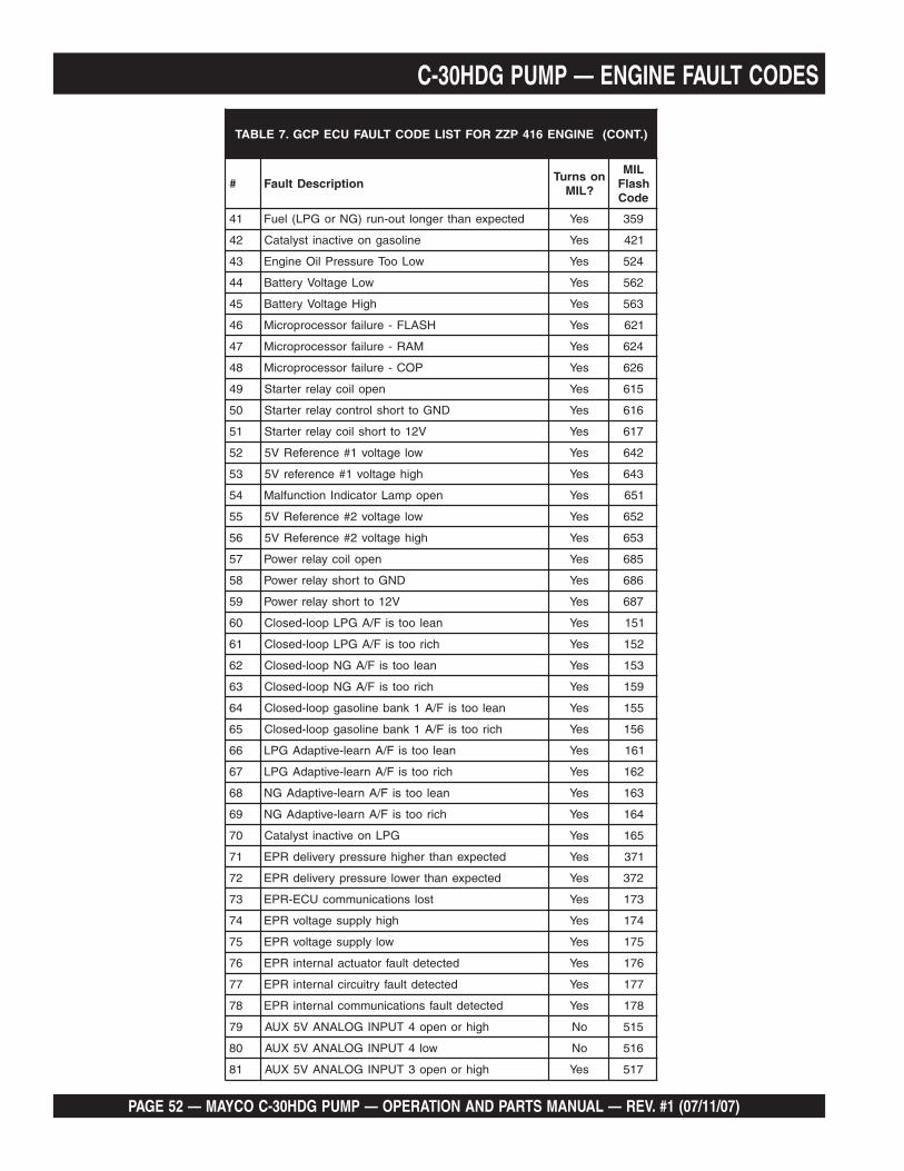
PAGE 52 — MAYCO C-30HDG PUMP — OPERATION AND PARTS MANUAL — REV. #1 (07/11/07)
C-30HDG PUMP — ENGINE FAULT CODES
).TNOC(ENIGNE614PZZROFTSILEDOCTLUAFUCEPCG.7ELBAT
# noitpircseDtluaFnosnruT
?LIM
LIMhsalFedoC
14 detcepxenahtregnoltuo-nur)GNroGPL(leuF seY 953
24 enilosagnoevitcanitsylataC seY 124
34 woLooTerusserPliOenignE seY 425
44 woLegatloVyrettaB seY 265
54 hgiHegatloVyrettaB seY 365
64 HSALF-eruliafrossecorporciM seY 126
74 MAR-eruliafrossecorporciM seY 426
84 POC-eruliafrossecorporciM seY 626
94 nepoliocyalerretratS seY 516
05 DNGottrohslortnocyalerretratS seY 616
15 V21ottrohsliocyalerretratS seY 716
25 wolegatlov1#ecnerefeRV5 seY 246
35 hgihegatlov1#ecnereferV5 seY 346
45 nepopmaLrotacidnInoitcnuflaM seY 156
55 wolegatlov2#ecnerefeRV5 seY 256
65 hgihegatlov2#ecnerefeRV5 seY 356
75 nepoliocyalerrewoP seY 586
85 DNGottrohsyalerrewoP seY 686
95 V21ottrohsyalerrewoP seY 786
06 naelootsiF/AGPLpool-desolC seY 151
16 hcirootsiF/AGPLpool-desolC seY 251
26 naelootsiF/AGNpool-desolC seY 351
36 hcirootsiF/AGNpool-desolC seY 951
46 naelootsiF/A1knabenilosagpool-desolC seY 551
56 hcirootsiF/A1knabenilosagpool-desolC seY 651
66 naelootsiF/Anrael-evitpadAGPL seY 161
76 hcirootsiF/Anrael-evitpadAGPL seY 261
86 naelootsiF/Anrael-evitpadAGN seY 361
96 hcirootsiF/Anrael-evitpadAGN seY 461
07 GPLnoevitcanitsylataC seY 561
17 detcepxenahtrehgiherusserpyreviledRPE seY 173
27 detcepxenahtrewolerusserpyreviledRPE seY 273
37 tsolsnoitacinummocUCE-RPE seY 371
47 hgihylppusegatlovRPE seY 471
57 wolylppusegatlovRPE seY 571
67 detcetedtluafrotautcalanretniRPE seY 671
77 detcetedtluafyrtiucriclanretniRPE seY 771
87 detcetedtluafsnoitacinummoclanretniRPE seY 871
97 hgihronepo4TUPNIGOLANAV5XUA oN 515
08 wol4TUPNIGOLANAV5XUA oN 615
18 hgihronepo3TUPNIGOLANAV5XUA seY 715

MAYCO C-30HDG PUMP — OPERATION AND PARTS MANUAL — REV. #1 (07/11/07) — PAGE 53
).TNOC(ENIGNE614PZZROFTSILEDOCTLUAFUCEPCG.7ELBAT
# noitpircseDtluaFnosnruT
?LIM
LIMhsalFedoC
28 wol3TUPNIGOLANAV5XUA seY 815
38 hgih1TUPNIGOLANAV5XUA seY 145
48 neporowol1TUPNIGOLANAV5XUA seY 245
58 neporohgih2TUPNIGOLANAV5XUA seY 345
68 wol2TUPNIGOLANAV5XUA seY 445
78 hgih1TUPNILATIGIDXUA seY 155
88 wol1TUPNILATIGIDXUA seY 255
98 hgih2TUPNILATIGIDXUA seY 355
09 wol2TUPNILATIGIDXUA seY 455
19 hgih3TUPNILATIGIDXUA seY 555
29 wol3TUPNILATIGIDXUA seY 655
39 hgihronepo5TUPNIGOLANAV5XUA seY 365
49 wol5TUPNIGOLANAV5XUA seY 465
59 )1ITR(stuptuodekcolbrossecorpgodhctaW seY 217
69 2ITR-eruliafrossecorporciM seY 317
79 3ITR-eruliafrossecorporciM seY 417
89 D/A-eruliafrossecorporciM seY 517
99 tpurretnI-eruliafrossecorporciM seY 617
001 DNGottrohs/nepo)4MWP_XUA(58niP seY 736
101 V21ottrohs)4MWP_XUA(58niP seY 836
201 DNGottrohslortnocLIM oN 446
301 V21ottrohslortnocLIM oN 546
401 SPTrewoLhcaerotelbanU seY 112
501 SPTrehgihhcaerotelbanU seY 212
601 SVInahtrehgih1PPA seY 513
701 tcilfnoCSVI/SPA seY 123
801 egatlovwollangis1PPA seY 223
901 egatlovhgihlangis1PPA seY 323
011 hctamsim2/1PPA,elditakcutsSVI seY 233
111 hctamsim2/1PPA,eldi-ffotakcutsSVI seY 133
211 timiLSVInahtrewol1PPA seY 933
311 tnerrucwolAliocnoitingI seY 114
411 tnerruchgihAliocnoitingI seY 214
511 tnerrucwolBliocnoitingI seY 124
611 tnerruchgihBliocnoitingI seY 224
711 tnerrucwolCliocnoitingI seY 134
811 tnerruchgihCliocnoitingI seY 234
911 tnerrucwolDliocnoitingI seY 144
021 tnerruchgihDliocnoitingI seY 244
C-30HDG PUMP — ENGINE FAULT CODES

PAGE 54 — MAYCO C-30HDG PUMP — OPERATION AND PARTS MANUAL — REV. #1 (07/11/07)
Figure 38. Zenith Fuel Injection System Wiring Diagram
C-30HDG PUMP — WIRING DIAGRAM (ZENITH WIRING HARNESS)

MAYCO C-30HDG PUMP — OPERATION AND PARTS MANUAL — REV. #1 (07/11/07) — PAGE 55
Figure 38. Zenith Fuel Injection System Wiring Diagram (Cont.)
C-30HDNI PUMP — WIRING DIAGRAM (ZENITH WIRING HARNESS)

PAGE 56 — MAYCO C-30HDG PUMP — OPERATION AND PARTS MANUAL — REV. #1 (07/11/07)
C-30HDG PUMP — WIRING DIAGRAM
Figure 39. Wiring Diagram
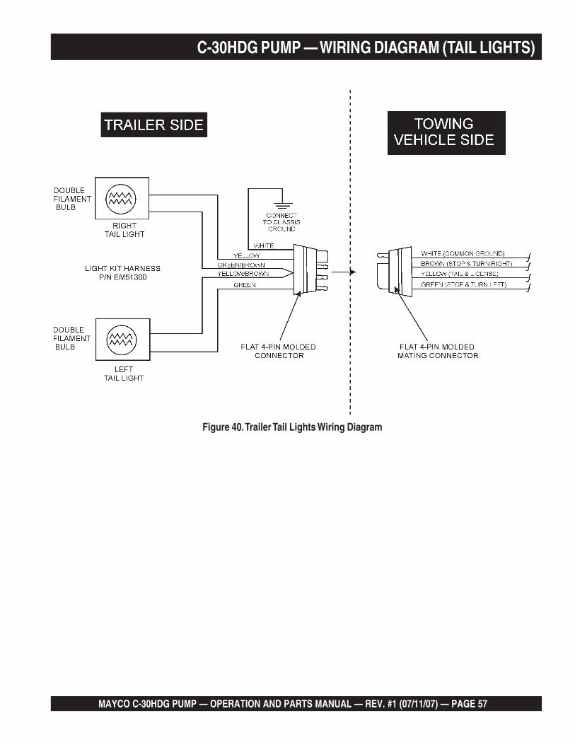
MAYCO C-30HDG PUMP — OPERATION AND PARTS MANUAL — REV. #1 (07/11/07) — PAGE 57
C-30HDG PUMP — WIRING DIAGRAM (TAIL LIGHTS)
Figure 40. Trailer Tail Lights Wiring Diagram

PAGE 58 — MAYCO C-30HDG PUMP — OPERATION AND PARTS MANUAL — REV. #1 (07/11/07)
Figure 41-A. Slump Test (1/3 Full)
Figure 41-C. Slump Test(Full-Overflow)
Figure 41-B. SlumpTest (2/3 Full)
Figure 41-D. Slump Test(Removing Excess Concrete)
Figure 41-E. Slump Test(Cone Invert)
Figure 41-F. Slump Test(Measurement)
1. To obtain a representative sample (concrete), take severalsamples at three or more regular intervals throughout thedischarge of the mixer or truck. DO NOT take samples at thebeginning or end of the discharge.
2. Dampen the inside of the cone and place it on a smooth, moist,nonabsorbent, level surface large enough to accommodateboth the slumped concrete and the slump cone. Stand on the“foot pieces” throughout the test procedure to hold the conefirmly in place.
3. Fill the cone 1/3 full by volume (Figure 38-A) and rod 25 timeswith a 1/2” dia x 24” lg. bullet-pointed steel rod. (This is aspecific requirement which will produce non-standard re-sults unless followed exactly.) Distribute rodding evenly overthe entire cross section of the sample.
4. Fill cone another 1/3 (Figure 38-B) which will make the cone2/3 full by volume. Rod this second layer 25 times with the rodpenetrating into, but not through, the first layer. Distributerodding evenly over the entire cross section of the layer.
5. Fill cone to overflowing (Figure 38-C). Rod this layer 25 timeswith rod penetrating into but not through, the second layer.Distribute rodding evenly over the entire cross section of thislayer.
6. Remove the excess concrete (Figure 38-D) from the top of thecone, using the tamping rod as a screed.
7. Lift the cone vertically (Figure 38-E) with a slow even motion.DO NOT jar the concrete or tilt the cone during this process.( Invert the withdrawn cone, and place it next to, but nottouching the slumped concrete.
8. Lay a straight edge (Figure 38-F) across the top of theslumped cone. Measure the amount of slump in inches fromthe bottom of the straight edge to the top of the slumpedconcrete at a point over the original center of the base . Theslump operation must be complete in a maximum elapsedtime of 1-1/2 minutes. Discard the concrete. DO NOT use it inany other tests.
APPENDIX — C-30HDNI C-30HDNI SLUMP TEST PROCEDURE
BULLET POINTEDSTEEL ROD
1/2 DIAMETER24 INCHES LONG
1/3 FULL
FOOTPIECE
2/3 FULL
FULL(OVERFLOW)

MAYCO C-30HDG PUMP — OPERATION AND PARTS MANUAL — REV. #1 (07/11/07) — PAGE 59
APPENDIX — C-30HDG CONCRETE MIX INFORMATIONThe following information has been extracted from actual testing laboratory reports. The purpose of this printing is only to helpcreate a better understanding of the importance of uniform gradation and proportioning of materials which affect pumpability ofconcrete mixes. These weights and proportions illustrate that when the sieve analysis is ideal, the sand/rock ratio can be adjusted(65% sand 35% rock) and pumpability should be excellent.
EXAMPLE #1 (A California Test Lab. Report)
JOB: Building Foundations (Water Project)
Sacks per cu./yd. 6.5 designed for 2,500 lbs. in 28 days
Gallons per sack 7.1
Washed Sand-#200 wash 1.3
Organic matter-OK
Specific gravity (SSD) Sand-2.58; Pea Gravel-2.60
Sieve analysis-percent passing
Material 1.5” 1” 3/4” 3/8” #4 #8 #16 #30 #50 #100 #200
W.C. Sand 100 99.7 79.1 60.4 36.5 14.3 4.0 1.1
Pea Gravel 100 3.0
% Comb. 100 66 51 39 23 9 3 1.0
DESIGN FOR ONE YARD OF CONCRETE (SATURATED & SURFACE DRY):
Absolute volume of aggregate in one cu. yard: 17.78 cu. ft.
Specific gravity of aggregates in one cu. yard: 2.58
Weight of aggregates in one cu. yard batch: 2850 lbs.
% BATCH SPEC. GRAVITY ABS. VOL.
W.C. Sand 65 1800 2.58 11.56
PEA GRAVEL 35 1000 2.60 6.22
WATER 46 gal. 1
CEMENT 6.5 sk. 611
TOTAL 27.00
ADMIXTURE: None
SLUMP 4”
REMARKS This mix designed for pumping
NOTE: Due to the availability of well-graded sand as shown in the above sieve analysis, this mix pumped very successfully.

PAGE 60 — MAYCO C-30HDG PUMP — OPERATION AND PARTS MANUAL — REV. #1 (07/11/07)
A.S.T.M. STANDARD SPECIFICATION FOR GRADING AGGREGATE
APPENDIX — C-30HDG CONCRETE MIX INFORMATION

MAYCO C-30HDG PUMP — OPERATION AND PARTS MANUAL — REV. #1 (07/11/07) — PAGE 61
APPENDIX — C-30HDG CONCRETE MIX INFORMATIONConsolidated Rock Products Co., Division of Tests3/8” Pea Gravel STANDARD PUMP MIXES (one-half inch minus)
NOTE: All weights shown are one cubic yard with S.S.D. aggregates.
CRP Mix Number 6004 .......................... 6005 .............................6006 .......................... 6007
Design Slump (in.) 6” (15 cm) ............. 6” (15 cm) .................6” (15 cm) ............. 6” (15 cm)
Cement, SACK. 7.0 ................................ 7.0 ......................................7.0 ................................ 7.0
Cement, Lbs. 658 (298 kg) ............ 658 (298 kg) ................658 (298 kg) ............ 658 (298 kg)
w/Con Sand (1 lb.) 2031 (920 kg) ............ 2982 (943 kg) ................1879 (851 kg) ............ 1943 (880 kg)
Gravel #4(9.51 mm) 677 (307 kg) ............ 693 (314 kg) ................806 (365 kg) ............ 832 (377 kg)
TOTAL AGGREGATE 2708 (1227 kg) .......... 2775 (1257 kg) .............2685 (1216 kg) .......... 2775 (1257 kg)
ADMIXTURE
Pozzolight 311-1 lb. 1.4 (.63 kg) ............. 1.4 (.63 kg) .................1.4 (.63 kg) ............. —
Water, Design (gals.) 50.0 (189 liters) ......... 53.0 (200 liters) ............50.0 (189 liters) ......... 53.9 (200 liters)
Mater, Max. (gals.) 50.0 (189 liters) ......... 53.0 (200 liters) ............53.0 (200 liters) ......... 53.0 (200 liters)
NOTE: Multiply above kilograms and liters by 1.308 to obtain the proportions for one cubic meter of concrete.
Consolidated Rock Products Co., Division of Tests
3/8” Pea Gravel STANDARD PUMP MIXES (one-half inch minus)
NOTE: All weights shown are one cubic yard with S.S.D. aggregates.
CRP Mix Number 6000 .......................... 6001 .............................6002 .......................... 6003
Design Slump (in.) 6” (15 cm) ............. 6” (15 cm) .................6” (15 cm) ............. 6” (15 cm)
Cement, SACK. 6.5 ................................ 6.5 ......................................6.5 ................................ 6.5
Cement. Lbs. 611 (276 kg) ........... 611 (276 kg) ................611 (276 kg) ............ 611 (276 kg)
w/Con Sand (1.1 lb.) 2062 (934 kg) ........... 2112 (957 kg) ................1924 (872 kg) ............ 1971 (893 kg)
Gravel #4 (9.51mm) 687 (311 kg) ........... 704 (319 kg) ................825 (374 kg) ............ 845 (383 kg)
TOTAL AGGREGATE 2749 (1245 kg) .......... 2816 (1276 kg) .............2749 (1245 kg) .......... 2816 (1276 kg)
ADMIXTURE
Pozzolight 311-1.3lb. 1.3 (.59 kg) ............. 1.3 (.59) ......................—
Water, Design (gals.) 50.0 (189 liters) ......... 53.0 (200 liters) ............50.0 (189 liters) ......... 53.9 (200 liters)
Mater, Max. (gals.) 50.0 (189 liters) ......... 53.0 (200 liters) ............53.0 (200 liters) ......... 53.0 (200 liters)
NOTE: Multiply above kilograms and liters by 1.308 to obtain the proportions for one cubic meter of concrete.

PAGE 62 — MAYCO C-30HDG PUMP — OPERATION AND PARTS MANUAL — REV. #1 (07/11/07)
APPENDIX — RECOMMENDED SHOTCRETE SYSTEMRECOMMENDED SHOTCRETE SYSTEM
Figure 42. Shotcrete System
MAY
C0
C-3
0HD
N
1-800-30-MAYCO
78
10
3
3
2
1
9
10
11 13 14 15
1/2 STANDARDAIR HOSE
AIR COMPRESSOR(125 TO 250 CFM)
3/4 STANDARDAIR HOSE

MAYCO C-30HDG PUMP — OPERATION AND PARTS MANUAL — REV. #1 (07/11/07) — PAGE 63
APPENDIX — RECOMMENDED SHOTCRETE SYSTEM
General recommendations
■ If the site will permit, use steel pipe from the pumpto the pool perimeter. It will reduce line pressureswhich is highly recommended.
■ The vibrator on the reducer by the pool improvespumpability.
■ Turn both air vibrators off whenever the pump isstopped to prevent separation of mix.
■ The air vibrators are low consumption (4.2 scfm).
■ Leave the air on at the nozzle when the pump isstopped to prevent clogging of air the hoses in theair insert.
■ Use item #11 (steel elbow) at the edge of the poolto prevent collapse of the rubber hose, which cancause blockage.
RECOMMENDED SHOTCRETE SYSTEM
NO. PART NO. PART NAME QTY. REMARKS1 EM28904 ........... 3" “B” COUPLING
2 EM23946 ........... 3"-90° ELBOW
3 EM28903 ........... 2 1/2" S/J COUPLING
4 EM28005DD ...... 3"X 2 1/2 REDUCER
5 EM28061 ........... 2 1/2"X 10FT. PIPE
6 EM24849 ........... 2 1/2"X 50FT. HOSE
7 EM28001DD ...... 2 1/2"X 2" REDUCER
8 EM23815D ........ 2 1/2"X 2" REDUCER
W/AIR VIBRATOR
9 EM28902 ........... 2" S/J COUPLING
10 EM23101 ........... AIR VIBRATOR
11 EM28131 ........... 2"X 2 ELBOW
12 EM24841 ........... 2"X 25 FT. HOSE
13 EM23808D ........ NOZZLE ASSEMBLY
14 EM23806 ........... 1 3/8" NOZZLE TIP
15 EM23807 ........... 1 1/4" NOZZLE TIP
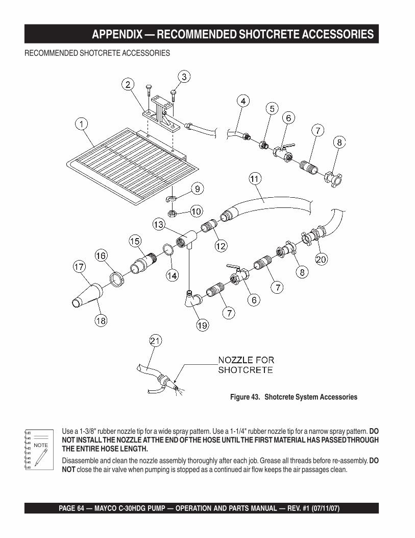
PAGE 64 — MAYCO C-30HDG PUMP — OPERATION AND PARTS MANUAL — REV. #1 (07/11/07)
APPENDIX — RECOMMENDED SHOTCRETE ACCESSORIESRECOMMENDED SHOTCRETE ACCESSORIES
Use a 1-3/8" rubber nozzle tip for a wide spray pattern. Use a 1-1/4" rubber nozzle tip for a narrow spray pattern. DONOT INSTALL THE NOZZLE AT THE END OF THE HOSE UNTIL THE FIRST MATERIAL HAS PASSED THROUGHTHE ENTIRE HOSE LENGTH.
Disassemble and clean the nozzle assembly thoroughly after each job. Grease all threads before re-assembly. DONOT close the air valve when pumping is stopped as a continued air flow keeps the air passages clean.
Figure 43. Shotcrete System Accessories
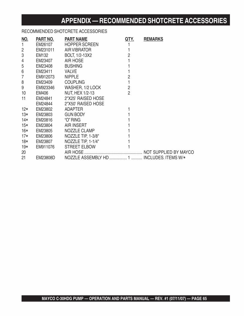
MAYCO C-30HDG PUMP — OPERATION AND PARTS MANUAL — REV. #1 (07/11/07) — PAGE 65
APPENDIX — RECOMMENDED SHOTCRETE ACCESSORIESRECOMMENDED SHOTCRETE ACCESSORIES
NO. PART NO. PART NAME QTY. REMARKS1 EM26107 HOPPER SCREEN 12 EM231011 AIR VIBRATOR 13 EM132 BOLT, 1/2-13X2 24 EM23407 AIR HOSE 15 EM23408 BUSHING 16 EM23411 VALVE 17 EM912073 NIPPLE 28 EM23409 COUPLING 19 EM923346 WASHER, 1/2 LOCK 210 EM406 NUT, HEX 1/2-13 211 EM24841 2"X25' RAISED HOSE
EM24844 2"X50' RAISED HOSE12* EM23802 ADAPTER 113* EM23803 GUN BODY 114* EM20816 “O” RING 115* EM23804 AIR INSERT 116* EM23805 NOZZLE CLAMP 117* EM23806 NOZZLE TIP, 1-3/8" 118* EM23807 NOZZLE TIP, 1-1/4" 119* EM911076 STREET ELBOW 120 AIR HOSE ..................................................... NOT SUPPLIED BY MAYCO21 EM23808D NOZZLE ASSEMBLY HD ................ 1 .......... INCLUDES. ITEMS W/*

PAGE 66 — MAYCO C-30HDG PUMP — OPERATION AND PARTS MANUAL — REV. #1 (07/11/07)
EXPLANATION OF CODE IN REMARKS COLUMN
The contents and part numbers listed in the parts section aresubject to change without notice. Multiquip does notguarantee the availibility of the parts listed.
When ordering a part that has more than oneitem number listed, check the remarks column forhelp in determining the proper part to order.
The following section explains the different symbols andremarks used in the Parts section of this manual. Use the helpnumbers found on the back page of the manual if there are anyquestions.
NO. Column
Unique Symbols - All items with same unique symbol(*, #, +, %, or >) in the number column belong to the sameassembly or kit, which is indicated by a note in the “Remarks”column.
Duplicate Item Numbers - Duplicate numbers indicatemultiple part numbers are in effect for the same generalitem, such as different size saw blade guards in use or apart that has been updated on newer versions of the samemachine.
Sample Parts List:NO. PART NO. PART NAME QTY. REMARKS1 12345 BOLT ...................... 1 ...... INCLUDES ITEMS W/*2* WASHER, 1/4 IN. ............. NOT SOLD SEPARATELY2* 12347 WASHER, 3/8 IN. ... 1 ......MQ-45T ONLY3 12348 HOSE ................... A/R ....MAKE LOCALLY4 12349 BEARING ............... 1 ......S/N 2345B AND ABOVE
PART NO. Column
Numbers Used - Part numbers can be indicated by anumber, a blank entry, or TBD.
TBD (To Be Determined) is generally used to show a partthat has not been assigned a formal part number at time ofpublication.
A blank entry generally indicates that the item is not soldseparately or is not sold by Multiquip. Other entries will beclarified in the “Remarks” Column.
QTY. Column
Numbers Used - Item quantity can be indicated by anumber, a blank entry, or A/R.
A/R (As Required) is generally used for hoses or other partsthat are sold in bulk and cut to length.
A blank entry generally indicates that the item is not soldseparately. Other entries will be clarified in the “Remarks”Column.
REMARKS Column
Some of the most common notes found in the “Remarks”Column are listed below. Other additional notes needed todescribe the item can also be shown.
Assembly/Kit - All items on the parts list with the sameunique symbol will be included when this item is purchased.
Indicated by:“INCLUDES ITEMS W/(unique symbol)”
Serial Number Break - Used to list an effective serialnumber range where a particular part is used.
Indicated by:“S/N XXXXX AND BELOW”“S/N XXXX AND ABOVE”“S/N XXXX TO S/N XXX”
Specific Model Number Use - Indicates that the part isused only with the specific model number or model numbervariant listed. It can also be used to show a part is NOTused on a specific model or model number variant.
Indicated by:“XXXXX ONLY”“NOT USED ON XXXX”
“Make/Obtain Locally” - Indicates that the part can bepurchased at any hardware shop or made out of availableitems. Examples include battery cables, shims, and certainwashers and nuts.
“Not Sold Separately” - Indicates that an item cannot bepurchased as a separate item and is either part of anassembly/kit that can be purchased, or is not available forsale through Multiquip.

MAYCO C-30HDG PUMP — OPERATION AND PARTS MANUAL — REV. #1 (07/11/07) — PAGE 67
C-30HDG CONCRETE PUMPW/ ZENITH FUEL INJECTION SYSTEM
1 UnitsQTY. P/N DESCRIPTION
6 ....... EM14904 ...................... PISTON CUP KITS4 ....... EM18804 ...................... 4 1/2" STEEL BALL4 ....... EM14818 ...................... 4" STEEL BALL6 ....... EM14903 ...................... BALL STOP PIN KIT
10 ...... EM18801 ...................... 0-RING MANIFOLD1 ....... EM14308 ...................... CHAIN2 ....... EM26313 ...................... HALF LINK2 ....... EM26314 ...................... MASTER LINK1 ....... EM14334 ...................... COMPENSATOR SPRING2 ....... EM14408 ...................... BRONZE RING2 ....... EM903092 .................... CAM ROLLER BEARING2 ....... EM14315 ...................... V-BELT2 ....... EM14842 ...................... LOWER SEAT2 ....... EM14843 ...................... UPPER SEAT2 ....... EM26310 ...................... CLUTCH LINING10 ...... EM18409 ...................... O-RING2 ....... EM20763 ...................... FUEL FILTER2 ....... EM20328TKIT ............... BEARING KIT1 ....... EM28004DD ................. REDUCER 3" X 2"1 ....... EM23946 ...................... 3" ELBOW2 ....... EM28904 ...................... 3" CLAMP4 ....... EM289041 .................... 3" GASKETS1 ....... EM14159 ...................... HOPPER SCREEN8 ....... 22401M7714 ................. SPARK PLUG
30 ...... EM98057A .................... "SLICK PACK"............................................... HOSE PRIMING AGENT
C-30HDG PUMP — SUGGESTED SPARE PARTSC-30HDG CONCRETE PUMP
W/ ZENITH FUEL INJECTION SYSTEM
3 UnitsQTY. P/N DESCRIPTION
10 ...... EM14904 ...................... PISTON CUP KITS10 ...... EM18804 ...................... 4 1/2" STEEL10 ...... EM14818 ...................... 4" STEEL BALL12 ...... EM14903 ...................... BALL STOP PIN KITS25 ...... EM18801 ...................... MANIFOLD O-RINGS3 ....... EM14308 ...................... CHAINS
10 ...... EM26313 ...................... HALF LINK10 ...... EM26314 ...................... MASTER LINK2 ....... EM14334 ...................... COMPENSATOR SPRING4 ....... EM14408 ...................... BRONZE RING2 ....... EM903092 .................... CAM ROLLER BEARING6 ....... EM14315 ...................... V-BELT6 ....... EM14842 ...................... LOWER SEAT6 ....... EM14843 ...................... UPPER SEAT3 ....... EM26310 ...................... CLUTCH LINING
20 ...... EM18409 ...................... O-RING6 ....... EM20763 ...................... FUEL FILTER2 ....... EM20328TKIT ............... BEARING KIT2 ....... EM28004DD ................. REDUCER 3" x 2"2 ....... EM23946 ...................... 3" ELBOW4 ....... EM28904 ...................... 3" CLAMP
10 ...... EM289041 .................... 3" GASKET2 ....... EM14159 ...................... HOPPER SCREEN1 ....... EM14300 ...................... CAM1 ....... EM14801 ...................... T-MANIFOLD1 ....... EM14819 ...................... Y-MANIFOLD2 ....... EM14335 ...................... PISTON ROD1 ....... EM26788 ...................... REMOTE SWITCH1 ....... EM903176 .................... CONN. ROD BEARING1 ....... EM14305 ...................... CRANKSHAFT2 ....... EM14807 ...................... PUMP CYLINDER2 ....... EM18800 ...................... COMPENSATOR CYLINDER1 ....... EM14320 ...................... CLUTCH
60 ...... EM98057A .................... "SLICK PACK"............................................... HOSE PRIMING AGENT
Part number on this Suggested Spare Parts Listmay super cede/replace the P/N shown in thetext pages of this book.

PAGE 68 — MAYCO C-30HDG PUMP — OPERATION AND PARTS MANUAL — REV. #1 (07/11/07)
C-30HDG PUMP — NAMEPLATE AND DECALS

MAYCO C-30HDG PUMP — OPERATION AND PARTS MANUAL — REV. #1 (07/11/07) — PAGE 69
C-30HDG PUMP — NAMEPLATE AND DECALSNAME PLATE AND DECALS
NO PART NO PART NAME QTY. REMARKS1* DCL152 DECAL, CAUTION OIL LEVEL 12 * EM932 DECAL, CAUTION, MANIFOLD 13 * EM1028 DECAL, MULTIQUIP MAYCO 24 * 508594 DECAL, CAUTION READ MANUAL 25 * EM517019 DECAL, C-30HDG 26 * EM513165 DECAL, MAINTENANCE 17 DECAL, NAME PLATE ............................. 1 ........... CONTACT MQ PARTS DEPT. W/
............................................................................... MODEL AND SERIAL NUMBER.8* 98022 DECAL, WARNING 19* 34536 DECAL, OWNER'S MANUAL 110 EM514274 KIT, DECAL .............................................. 1 ........... INCLUDES ITEMS W/ *

PAGE 70 — MAYCO C-30HDG PUMP — OPERATION AND PARTS MANUAL — REV. #1 (07/11/07)
COMPENSATOR PISTON ROD ASSY.
C-30HDG PUMP — COMPENSATOR PISTON ROD ASSY.

MAYCO C-30HDG PUMP — OPERATION AND PARTS MANUAL — REV. #1 (07/11/07) — PAGE 71
C-30HDG PUMP — COMPENSATOR PISTON ROD ASSY.COMPENSATOR PISTON ROD ASSY.
NO. PART NO. PART NAME QTY. REMARKS1 EM14805 ROD END ................................... 1 ........... INCLUDES ITEMS W/+1A+ EM148053 BUSHING 12 EM968446 NUT HEX, 3/4”-10 GR5 23 EM14332 ROD SPRING GUIDE 3/4” 14 EM14331 SPRING BACKING PLATE 15 EM14333 SPRING RETURN 16 EM14806 PISTON GUIDE ASSY. 17 EM505490 FITTING 18* EM903163 BEARING CUP 19* EM20814 BEARING BUSHING 110* EM20813 SPACER 111* EM903162 BEARING CONE 212* EM20816 O-RING 213 EM916001 FITTING 214 EM510266 SCREW, HHC 1/2-13X3 115 EM621 WASHER 216 492584 NUT LOCK 1/2” DIA. 117 EM14335 PISTON ROD 118 EM14336 PISTON GUIDE 119 EM505489 FITTING 120 EM14334 COMPENSATOR SPRING 121 EM18409 O-RING 122 EM98032 PLATE, OILER 123 EM14407 O-RING, OILER PLATE 124 EM14410 RING & FELT HOLDER 125 EM14408 BRONZE RING 126 EM14411 PISTON CUP-BLACK 126 EM98051 PISTON CUP-ORANGE 127 EM14412 BUSHING 1 1/4 CRS 128 EM18409 O-RING 1” 229 EM14413 FACE PLATE 130 EM18800HD PUMPING CYLINDER ................ 1 ............ 2-1/2" LIP SLEEVE31 EM26525 O-RING, CYLINDER BOX 132 EM968446 NUT HEX, 3/4-10 333 EM16493 FELT RING 134 EM148053 BUSHING 135 EM20328TKIT BEARING KIT ............................ 1 ............ INCLUDES ITEMS W/*

PAGE 72 — MAYCO C-30HDG PUMP — OPERATION AND PARTS MANUAL — REV. #1 (07/11/07)
C-30HDG PUMP — CONNECTING ROD - DRIVE SIDE ASSY.CONNECTING ROD - DRIVE SIDE ASSY.

MAYCO C-30HDG PUMP — OPERATION AND PARTS MANUAL — REV. #1 (07/11/07) — PAGE 73
C-30HDG PUMP — CONNECTING ROD - DRIVE SIDE ASSY.CONNECTING ROD - DRIVE SIDE ASSY.
NO. PART NO. PART NAME QTY. REMARKS7 EM505490 FITTING 18* EM903163 BEARING CUP 19* EM20814 BEARING BUSHING 110* EM20813 SPACER 111* EM903162 BEARING CONE 212* EM20816 O-RING 221 EM18409 O-RING 122 EM98032 PLATE, OILER 123 EM14407 O-RING, OILER PLATE 124 EM14408 BRONZE RING 125 EM14410 RING AND FELT HOLDER 126 EM14411 PISTON CUP-BLACK 126 EM98051 PISTON CUP-ORANGE 127 EM14412 BUSHING 1 1/4 CRS 128 EM18409 O-RING 1” 229 EM14413 FACE PLATE 130 EM14807HD CONCRETE CYLINDER ............. 1 ............ 3-3/4 IN. LIP SLEEVE32 EM968446 NUT HEX, 3/4-10 333 EM14808 PISTON ROD ASSY. 134 EM16493 FELT RING 135 EM20328TKIT BEARING KIT ............................ 1 ............ INCLUDES ITEMS W/*

PAGE 74 — MAYCO C-30HDG PUMP — OPERATION AND PARTS MANUAL — REV. #1 (07/11/07)
ROCKER ASSY.
C-30HDG PUMP — ROCKER ASSY.
17
16
15
13
12
27
7
25
44
5 8
9
10
11
6
3
7
7
10
20 31
2423
8
2423
22
21
30
28
7
1
35
27
45
14
7
31
7
7
AB
C
3
4
2
19
NOTES:
A. LONG STROKE SETTING.HIGHER VOLUME, LOWER PSI.
B. STANDARD SETTING, NORMAL.C. SHORT STROKE SETTING.
REDUCED VOLUME, HIGHER PSI.
SEE CRANKSHAFT ASSEMBLY
1
2
1
LUBRICATIONPOINT
LUBRICATIONPOINT
LUBRICATIONPOINT
LUBRICATIONPOINT
2
PART OFFRAME
6
25
1
8
41
3637
38 37
40
LUBRICATIONPOINT
43
46
KIT

MAYCO C-30HDG PUMP — OPERATION AND PARTS MANUAL — REV. #1 (07/11/07) — PAGE 75
C-30HDG PUMP — ROCKER ASSY.ROCKER ASSY.
NO. PART NO. PART NAME QTY. REMARKS1 EM503073 SHAFT ROCKER ARM 12 EM14116 JOURNAL BLOCK 13 EM963180 SCREW, HHC 3/4”-10X5 24 EM923350 WASHER LOCK 3/4” SPRING STEEL 25 EM14846 CAM ROCKER ARM ..................................... 1......... INCLUDES ITEMS W/+6 EM133 BOLT 1”-14X2” HEX HEAD 17 EM603 WASHER 1” LOCK 18 EM916001 ZERK FITTING 19 EM903092 BEARING ASSY. 110 EM20347 BEARING SPACER 211 EM402434 BEARING BUSHING 112 EM20344 SPECIAL BOLT 113 EM916001 ZERK FITTING 114 EM417 NUT FLEX LOCK 115 EM402456 OILER FELT 216 EM607 WASHER, FLAT 5/8” 117 EM20349 OILER PLUG, PLASTIC 119 EM969038 NUT STOP REG. 3/4”-10 120% EM903163 BEARING CUP 121% EM20814 BEARING BUSHING 122% EM20813 SPACER 123% EM903162 BEARING CONE 224% EM20816 O-RING 225 EM105 BOLT 1”-14X6” HEX HEAD 127#+ EM203262 BRONZE BUSHING 428 EM20364 CONNECTING ROD 130 EM702 SCREW ALLEN HEAD 3/8”-16X3/4” 131 EM505490 ZERK FITTING 135 EM14328 ROCKER ARM ASSY. ................................... 1......... INCLUDES ITEM W/#36 EM20338 SPACER 137 EM20336 O-RING 138 EM903176 BEARING 140 EM402996 SEAL PLATE 141 EM923348 WASHER LOCK 5/8 142 EM503982 BOLT 1/2-13X5 143 EM98043 FORGED CRANKSHAFT .............................. 1......... INCLUDES ITEM W/*44 EM417 NUT, LOCK 3/4"-10 245 EM202 BOLT, HEX 1-8 X 6 LG. 146 EM20328TKIT BEARING KIT ............................................... 1......... INCLUDES ITEMS W/%

PAGE 76 — MAYCO C-30HDG PUMP — OPERATION AND PARTS MANUAL — REV. #1 (07/11/07)
C-30HDG PUMP — COUNTER-SHAFT ASSY.COUNTERSHAFT ASSY.
9
12
11
12
8
7
2
6
21
3
4
7
12
6
6
5
6
5
6
22
60
21
3
4
59 61
55
12
NOTES:
SEE CLUTCH ASSEMBLYPAGES 84 AND 85.
SEE CRANKCASE ASSEMBLY,PAGES 74 AND 75,
1
2
LUBRICATIONPOINT
LUBRICATIONPOINT
1
2
PART OFFRAME
MASTERLINK HALF
LINK
PART OFFRAME
aaaaaaaaaaaaaaaaaaaaaaaaaaaaaaaaaaaaaaaaaaaaaaaaaaaaaaaaaaaaaaaaaaaaaaaaaaaaaaaaaaaaaaaaaaaaaaaaaaaaaaaaaaaaaaaaaaaaaaaaaaaaaaaaaaaaaaaaaaaaaaaaaaaaaaaaaaaaaaaaaaaaaaaaaaaaaaaaaaaaaaaaaaaaaaaaaaaaaaaaaaaaaaaaaaaaaaaaaaaaaaaaaaaaaaaaaaaaaaaaaaaaaaaaaaaaaaaaaaaaaaaaaaaaaaaaaaaaaaaaaaaaaaaaaaaaaaaaaaaaaaaaaaaaaaaaaaaaaaaaaaaaaaaaaaaaaaaaaaaaaaaaaaaaaaaaaaaaaaaaaaaaaaaaaaaaaaaaaaaaaaaaaaaaaaaaaaaaaaaaaaaaaaaaaaaaaaaaaaaaaaaaaaaaaaaaaaaaaaaaaaaaaaaaaaaaaaaaaaaaaaaaaaaaaaaaaaaaaaaaaaaaaaaaaaaaaaaaaaaaaaaaaaaaaaaaaaaaaaaaaaaaaaaaaaaaaaaaaaaaaaaaaaaaaaaaaaaaaaa
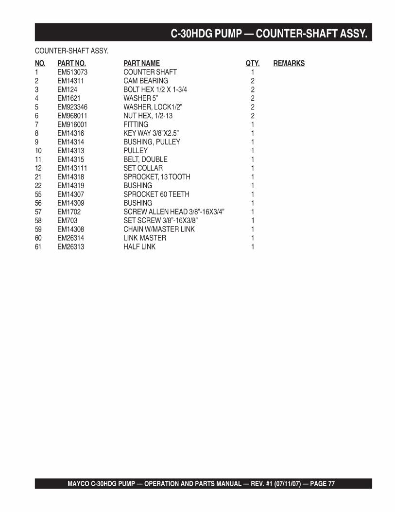
MAYCO C-30HDG PUMP — OPERATION AND PARTS MANUAL — REV. #1 (07/11/07) — PAGE 77
C-30HDG PUMP — COUNTER-SHAFT ASSY.COUNTER-SHAFT ASSY.
NO. PART NO. PART NAME QTY. REMARKS1 EM513073 COUNTER SHAFT 12 EM14311 CAM BEARING 23 EM124 BOLT HEX 1/2 X 1-3/4 24 EM1621 WASHER 5” 25 EM923346 WASHER, LOCK1/2” 26 EM968011 NUT HEX, 1/2-13 27 EM916001 FITTING 18 EM14316 KEY WAY 3/8”X2.5” 19 EM14314 BUSHING, PULLEY 110 EM14313 PULLEY 111 EM14315 BELT, DOUBLE 112 EM143111 SET COLLAR 121 EM14318 SPROCKET, 13 TOOTH 122 EM14319 BUSHING 155 EM14307 SPROCKET 60 TEETH 156 EM14309 BUSHING 157 EM1702 SCREW ALLEN HEAD 3/8”-16X3/4” 158 EM703 SET SCREW 3/8”-16X3/8” 159 EM14308 CHAIN W/MASTER LINK 160 EM26314 LINK MASTER 161 EM26313 HALF LINK 1

PAGE 78 — MAYCO C-30HDG PUMP — OPERATION AND PARTS MANUAL — REV. #1 (07/11/07)
C-30HDG PUMP — CRANKSHAFT ASSY.CRANKSHAFT ASSY.
35
35
3332
31
25
28
2731
32
44
4326
23
2930
34
45
54
41
52
51
46
24
56
55
49
46
24
48
50
24
LUBRICATIONPOINT
LUBRICATIONPOINT
NOTES:
SEE ROCKER ARM ASSEMBLYITEM 43 FOR ASSOCIATEDCRANKSHAFT COMPONENTS.
SEE COUNTER-SHAFT ASSEMBLY,ITEM 55.
1
2
1
2
57
KIT
42
aaaaaaaaaaaaaaaaaaaaaaaaaaaaaaaaaaaaaaaaaaaaaaaaaaaaaaaaaaaaaaaaaaaaaaaaaaaaaaaaaaaaaaaaaaaaaaaaaaaaaaaaaaaaaaaaaaaaaaaaaaaaaaaaaaaaaaaaaaaaaaaaaaaaaaaaaaaaaaaaaaaaaaaaaaaaaaaaaaaaaaaaaaaaaaaaaaaaaaaaaaaaaaaaaaaaaaaaaaaaaaaaaaaaaaaaaaaaaaaaaaaaaaaaaaaaaaaaaaaaaaaaaaaaaaaaaaaaaaaaaaaaaaaaaaaaaaaaaaaaaaaaaaaaaaaaaaaaaaaaaaaaaaaaaaaaaaaaaaaaaaaaaaaaaaaaaaaaaaaaaaaaaaaaaaaaaaaaaaaaaaaaaaaaaaaaaaaaaaaaaaaaaaaaaaaaaaaaaaaaaaaaaaaaaaaaaaaaaaaaaaaaaaaaaaaaaaaaaaaaaaaaaaaaaaaaaaaaaaaaaaaaaaaaaaaaaaaaaaaaaaaaaaaaaaaaaaaaaaaaaaaaaaaaaaaaaaaaaaaaaaaaaaaaaaaaaaaaaaa

MAYCO C-30HDG PUMP — OPERATION AND PARTS MANUAL — REV. #1 (07/11/07) — PAGE 79
C-30HDG PUMP — CRANKSHAFT ASSY.CRANKSHAFT ASSY.
NO. PART NO. PART NAME QTY. REMARKS23* EM14303 BEARING BLOCK 124* EM702 SCREW, ALLEN HEAD 3/8-16X3/4 625 EM505490 ZERK FITTING 126 EM129 SCREW, HHC 3/4-10X8-1/2 227 EM492628 LOCK WASHER 3/4 228 EM968446 NUT HEX, 3/4-10 GR5 429* EM14324 CUP BEARING 130* EM14323 SPACER BEARING CONE 131* EM14325 CONE BEARING 232* EM14326 O-RING 233* EM14322 SPACER 134* EM98043 CRANKSHAFT, FORGED 135* EM14306 KEY CRANKSHAFT 238 EM903176 BEARING 140 EM402996 SEAL PLATE 141 EM923348 WASHER, LOCK 5/8" 243* EM14302 SPACER, CAM BUSHING 144* EM14300 CAM ASSY. 145* EM14301 BUSHING, CAM 146* EM703 SCREW ALLEN HEAD 3/8-16X3/8 648* EM175 BOLT 3/8-16X1-1/4 649* EM14304 BEARING-CAM COMPLETE 150* EM916001 ZERK FITTING 151 EM128 BOLT 5/8-11X4” HEX HEAD 252 EM505882 WASHER, SPECIAL 5/8” 254 EM968013 NUT HEX 5/8-11 455* EM14307 SPROCKET 60 TEETH 156* EM14309 BUSHING 157 EM98043K CRANKSHAFT FORGE ASSEMBLY ............ 1......... INCLUDES ITEM W/*

PAGE 80 — MAYCO C-30HDG PUMP — OPERATION AND PARTS MANUAL — REV. #1 (07/11/07)
C-30HDG PUMP — MANIFOLD ASSY.MANIFOLD ASSY.
2
5
1 4
3
31
30
33
34
35
36
732
1413
1211
615
16
17
9
1413
1819
29
27
38
32
27
37
21
28
8
12
7
7
26
2627
1424
2311
PART OFFRAME
PART OFFRAME
ACCESSORIES
7
aaaaaaaaaaaaaaaaaaaaaaaaaaaaaaaaaaaaaaaaaaaaaaaaaaaaaaaaaaaaaaaaaaaaaaaaaaaaaaaaaaaaaaaaaaaaaaaaaaaaaaaaaaaaaaaaaaaaaaaaaaaaaaaaaaaaaaaaaaaaaaaaaaaaaaaaaaaaaaaaaaaaaaaaaaaaaaaaaaaaaaaaaaaaaaaaaaaaaaaaaaaaaaaaaaaaaaaaaaaaaaaaaaaaaaaaaaaaaaaaaaaaaaaaaaaaaaaaaaaaaaaaaaaaaaaaaaaaaaaaaaaaaaaaaaaaaaaaaaaaaaaaaaaaaaaaaaaaaaaaaaaaaaaaaaaaaaaaaaaaaaaaaaaaaaaaaaaaaaaaaaaaaaaaaaaaaaaaaaaaaaaaaaaaaaaaaaaaaaaaaaaaaaaaaaaaaaaaaaaaaaaaaaaaaaaaaaaaaaaaaaaaaaaaaaaaaaaaaaaaaaaaaaaaaaaaaaaaaaaaaaaaaaaaaaaaaaaaaaaaaaaaaaaaaaaaaaaaaaaaaaaaaaaaaaaaaaaaaaaaaaaaaaaaaaaaaaaaaaa

MAYCO C-30HDG PUMP — OPERATION AND PARTS MANUAL — REV. #1 (07/11/07) — PAGE 81
C-30HDG PUMP — MANIFOLD ASSY.MANIFOLD ASSY.
NO. PART NO. PART NAME QTY. REMARKS1 EM23946 ELBOW 3”X90 DEG.HD 12 EM28004DD REDUCER 3X2X36 HD 13 EM2C0B BALL 2” SPONGE 24 EM28904 COUPLING 3” HD *CF* 25 EM18409 O-RING 1” 46 EM14843 UPPER DURASEAT 17 EM18801 O-RING 68 EM18804 BALL 4-1/2” 19 EM14801 MANIFOLD T ASSY. 111 EM136 PIN BALL STOP 3/4-16 x 8 312 EM18409 O-RING 413 EM618 WASHER SPECIAL 414 EM968266 NUT JAM HEX 3/4-16 415 EM104 BOLT 5/8-11X2” HEX HEAD 316 EM923348 WASHER LOCK 5/8 SPRING 317 EM505882 WASHER, 5/8 318 EM14842 SEAT DURA LOWER 119 EM14818 BALL 4” 121 EM14819A MANIFOLD ASSY. EASY OPEN 123 EM18409 O-RING 224 EM618 WASHER SPECIAL 226 EM137 TEE-BOLT 3/4-10X14” 227 EM619 WASHER 3/4” 228 EM968446 NUT HEX 3/4”-10 GR5 230 EM14850 EXHAUST GATE “H/D” 131 EM963180 CAPSCREW 3/4-10X5 HEX HD G8 132 EM969038 NUT STOP REG.3/4-10 233 EM14845 ARM CLAMP 134 EM135 BOLT 1-1/4” -12X7” HEX HD. 135 EM14810 SPRING 136 EM451 NUT 1-1/4” -12 LOCK 137 EM160 BOLT 3/8-16X3/4” 138 EM509329 SCREW HHC 3/4-10X6 1

PAGE 82 — MAYCO C-30HDG PUMP — OPERATION AND PARTS MANUAL — REV. #1 (07/11/07)
C-30HDG PUMP — FRAME ASSY.
FRAME ASSY.

MAYCO C-30HDG PUMP — OPERATION AND PARTS MANUAL — REV. #1 (07/11/07) — PAGE 83
C-30HDG PUMP — FRAME ASSY. FRAME ASSY.
NO. PART NO. PART NAME QTY. REMARKS1 EM513085 FRAME ASSEMBLY 12 EM70186 JACK STAND, REAR 13 EM744 CLEVIS PIN 1/2” X 4” 14 EM745 HAIR PIN C 5/8- 3/4” 15 EM14600A AXLE, ASSEMBLY 17 501299 WASHER THICK 1” 28 491689 KEY COTTER 1/8 X 2 210 EM492396 SCREW HHC 1/2- 13 X 2 411 EM621 WASHER .5” 412 EM406 NUT LOCK 1/2” DIA. 413 EM511418 FENDER RIGHT-SIDE 114 981635 BOLT, HHC 1/2- 13 X 3/4 615 6109180 WASHER LOCK 1/2” 616 EM512251 COVER 117 EM512252 COVER 118 EM512253 COVER 119 EM512250 COVER 120 EM492309 SCREW, HHC 1621 0166 A WASHER, LOCK 3/8” 2422 EM512263 ROD 123 EM507895 PLUG, 2 1/2 NPT 226 29228 HITCH, TONGUE 2" 127 EM969023 NUT, HEX 5/8" NC 228 EM507658 SCREW, HHC 5/8" NC 4-1/2 G5 229 EM509947 LINK, QUICK 230 EM14165 BOLT EYE 231 EM619 WASHER 3/4” WILLIAM 232 EM968002 NUT COUPLING 3/4- 10 233 EM505121 SCREW 3/4”- 10 X 3 GR.5 234 EM969038 NUT STOP REG. 3/4- 10 235 EM513078 COVER, CHASSIS BOTTOM 136 10136 WASHER, FLAT 3/8 837 EM492264 HHCS. 3/8" NC X 1" 838 EM929028 HOOD REST, STEEL 239 492363 SCREW HHC 5/16- 18 X 3/4” 440 EM923343 WASHER LOCK 5/16” 441 EM265361 BRACKET LIGHT 242 EM26536 TAIL LIGHT 243 491010 HOOD FASTENER, RUBBER 244 EM513087 FENDER LEFT-SIDE 145 EM25610 JACK STAND, FRONT 1

PAGE 84 — MAYCO C-30HDG PUMP — OPERATION AND PARTS MANUAL — REV. #1 (07/11/07)
C-30HDG PUMP — AXLE ASSY.
AXLE ASSY.

MAYCO C-30HDG PUMP — OPERATION AND PARTS MANUAL — REV. #1 (07/11/07) — PAGE 85
C-30HDG PUMP — AXLE ASSY.AXLE ASSY.
NO. PART NO. PART NAME QTY. REMARKS1 EM26518 CAP 14” CHROME 22 EM26615A TIRE ASSY. ................................ 2 ........... INCLUDES ITEMS W/*3* WHEEL ....................................... 2 ........... CANNOT BE PURCHASED SEPARATELY4* TIRE 14" ..................................... 2 ........... CANNOT BE PURCHASED SEPARATELY5# EM26306 DUST COVER 26# EM968481 CASTLE NUT 27 EM705 PIN, COTTER 3/16X1 1/2 28# EM26329 WASHER 29# EM903113 OUTER BEARING 210# EM903012 OUTER CUP 211# EM26519 NUT 1212# EM20612 STUD 1213# EM26300 HUB 214# EM903169 INNER CUP 215# EM903168 INNER BEARING 216# EM26305 GREASE SEAL 217% EM20601 HUB ASSEMBLY ........................ 2 ........... INCLUDES ITEMS W/#18% EM14600 AXLE 119 EM14600A AXLE WITH HUBS INSTALLED ..... 1 .......... INCLUDES ITEMS W/%

PAGE 86 — MAYCO C-30HDG PUMP — OPERATION AND PARTS MANUAL — REV. #1 (07/11/07)
C-30HDG PUMP — MUFFLER, AIR FILTER, AND STOP SWITCH ASSY.
MUFFLER, AIR FILTER AND STOP SWITCH ASSY.

MAYCO C-30HDG PUMP — OPERATION AND PARTS MANUAL — REV. #1 (07/11/07) — PAGE 87
C-30HDG PUMP — MUFFLER, AIR FILTER, AND STOP SWITCH ASSY.MUFFLER, AIR FILTER AND STOP SWITCH ASSY.
NO. PART NO. PART NAME QTY. REMARKS1 EM98076 FILTER, AIR 12 EM98162 PRECLEANER, AIR FILTER 13 ZE1 ELEMENT, AIR FILTER 14 EM491873 GLAND CONNECTOR 15 EM14217 STOP SWITCH, ENGINE COVER 16 ZPPC6741620 CATALYTIC CONVERTER ........................................ 1.......... INCLUDED W/ENGINE7 ZPPC14667 GASKET................................................................... 2.......... INCLUDED W/ENGINE102 492363 BOLT, 5/16" DIA NC X 3/4" G5 3103 2105164 NUT, LOCK 5/16" 1104 EM923023 WASHER FLAT 5/16" 3106 2105164 NUT 5/16" 2107 EM516995 PANEL, FILTER SUPPORT 1112 EM513102 FLEX HOSE, AIR CLEANER 2" 1132 EM513110 SHOCK MOUNT 8133 EM923057 WASHER 1/4" 8134 EM98078 CLAMP 2135 2101402 WASHER SPRING 1/4" 8136 517293 MUFFLER 1137 EM968435 NUT HEX 1/4-20 8140 EM517292 EXHAUST PIPE 1184 EM513126 CLAMP 2195 EM516996 BRACKET 1202 3019092 WASHER FLAT 3/8" 2204 0166 A WASHER LOCK 3/8" MED 6206 EM963610 CAPSCREW 3/8" NC X 1-1/4" G8 2208 1456 NUT HEX FINISH 3/8-16 6210 492378 BOLT HHSC G-5 4212 EM504679 WASHER FLAT 3/8" 8236 EM515458 SUPPORT FRONT 2446 19633 BUSHING, RUBBER FUEL 1448 12008 FITTING, 90° 1460 EM505831 GASKET 1

PAGE 88 — MAYCO C-30HDG PUMP — OPERATION AND PARTS MANUAL — REV. #1 (07/11/07)
C-30HDG PUMP — CLUTCH ASSY.CLUTCH ASSY.

MAYCO C-30HDG PUMP — OPERATION AND PARTS MANUAL — REV. #1 (07/11/07) — PAGE 89
C-30HDG PUMP — CLUTCH ASSY.CLUTCH ASSY.
NO. PART NO. PART NAME QTY. REMARKS1* 492395 SCREW, HHC 1/2- 13X1-3/4” 12* EM923346 WASHER, LOCK 1/2” 13* EM621 WASHER, FLAT 1/2” SPECIAL 14* EM26321 ROTOR ASSEMBLY 15* EM918050 CLUTCH SPRING 26* EM26310 CLUTCH LINING 18* EM902204 CLUTCH BEARING 29* EM926066 RETAINING RING 210* EM926053 RETAINING RING 111* EM508342 SCREW, HHC M8X25 PI.25 612* EM26322 CLUTCH HOUSING W/LINING 113 0166A WASHER, LOCK 3/8” 614 EM517015 SHAFT STUB (FLANGE), ENGINE 115 EM26348 KEY 116 EM14320 CLUTCH COMPLETE ASSEMBLY ............. 1 ............. INCLUDES ITEMS W/*

PAGE 90 — MAYCO C-30HDG PUMP — OPERATION AND PARTS MANUAL — REV. #1 (07/11/07)
C-30HDG PUMP — ENGINE MOUNTING BRACKETS ASSY.ENGINE MOUNTING BRACKETS ASSY.

MAYCO C-30HDG PUMP — OPERATION AND PARTS MANUAL — REV. #1 (07/11/07) — PAGE 91
C-30HDG PUMP — ENGINE MOUNTING BRACKETS ASSY.ENGINE MOUNTING BRACKETS ASSY.
NO. PART NO. PART NAME QTY. REMARKS1 EM517379 SUPPORT BRACKET, RIGHT 12 EM517418 SUPPORT BRACKET, LEFT 13 20900059 SPACER, 20 OD X 11 ID X 32 LONG 14 20900063 SPACER, 76 X 30 X 6.35 25 21000205 BRACKET, ECU MOUNT 17 64700072 PLAIN WASHER, 10MM 48 64700073 HELICAL SPRING LOCK WASHER, 10MM 49 64700079 PLAIN WASHER, 8MM 110 64700080 HELICAL SPRING LOCK WASHER, 8MM 113 64900022 HEX SERRATED FLANGE CAP SCREW, M8-1.25 X 20 214 64900083 HEX CAP SCREW, M10-1.25X35 215 64900160 HEX CAP SCREW, M10-1.25X30 218 64900205 HEX CAP SCREW, M8/1.25 X 60 120 EM516977 ENGINE, HYUNDAI ZENITH C-30 130 EM516981 BRACKET RISER 232 EM513204 BOLT 1/2" NC X 5" 234 6109180 WASHER, LOCK 1/2" 644 6109170 WASHER, FLAT 1/2" 1446 6109160 HEX NUT, 1/2-13 1447 492580 NUT, 1/2" 248 EM505123 BOLT HEX 1/2 X 2-1/2" 249 EM513089 THREADED PIECE 250 EM517487 SUPPORT BRACKET, REAR 151 BOLT ...................................................................................... 2............. INCLUDED W/ENGINE52 WASHER ............................................................................... 2............. INCLUDED W/ENGINE53 WASHER ............................................................................... 2............. INCLUDED W/ENGINE54 NUT ........................................................................................ 2............. INCLUDED W/ENGINE322 EM506886 BOLT M8X20 1324 EM923343 WASHER LOCK 5/16" 1432 EM513094 BOLT, 1/2" NC X 1-3/4" 4330 EM517024 CLUTCH GUARD 1380 EM517351 GUARD 1

PAGE 92 — MAYCO C-30HDG PUMP — OPERATION AND PARTS MANUAL — REV. #1 (07/11/07)
C-30HDG PUMP — RADIATOR, MOUNTING BRACKET AND HOSES ASSY.RADIATOR, BRACKET AND HOSES ASSY.

MAYCO C-30HDG PUMP — OPERATION AND PARTS MANUAL — REV. #1 (07/11/07) — PAGE 93
RADIATOR, BRACKET AND HOSES ASSY.
NO. PART NO. PART NAME QTY. REMARKS1 20800072 BRACKET, TOP MOUNT 12 21000161 BRACKET, TUBE SUPPORT 13 62410120 CONNECTOR, STRAIGHT 410 X 32 DIA 24 64700072 PLAIN WASHER, 10 MM 15 64700073 HELICAL SPRING LOCK WASHER, 12MM 16 64700098 WASHER, PLAIN 12MM X 23.7MM 27 64700126 HELICAL SPRING LOCK WASHER, 12MM 28 64800164 NUT, LOCK, FLANGE, M6-1 49 64900002 HEX CAP SCREW, M12-1.25 X 30 210 64900026 HEX SERRATED FLANGE CAP SCREW, M6-1 X 20 411 64900035 HEX SERRATED FLANGE CAP SCREW, M10-1.25 X 20 312 64900083 HEX CAP SCREW, M10-1.25 X 35 113 64900174 HEX SERRATED FLANGE CAP SCREW, M8-1.25 X 16 114 65500001 ISOLATOR, 32 X32, M8-1.25 115 68800001 CLAMP, HOSE, WORM-DRIVE 816 68800018 CLAMP, TUBE/HOSE, LOOP/OFFSET 417 68900360 HOSE, 20R4, DIA 32, HYUNDAI 1.6 TOP REAR 118 68900359 HOSE, 20R4, DIA 32, HYUNDAI 1.6 LOWER REAR 119 68900361 HOSE, 20R4, DIA 32, HYUNDAI 1.6 TOP FRONT 120 68900362 HOSE, 20R4, DIA 32, HYUNDAI 1.6 FRONT BOTTOM 121 492356 BOLT, 1/4" X 3/4" 222 2101402 WASHER SPRING 1/4" 223 EM513116 CLAMP 1/2" 224 EM514536 HOSE 125 22000184 BRACKET, CROSS 126 65500002 ISOLATOR, 46.4MM, 51.21MM, 1/2-13 227 64700096 LARGE OD PLAIN WASHER, 1/2 X 2 X 1/8 228 64900182 HEX CAP SCREW, 1/2 - 13 X 2-1/2 229 64800059 HEX SERRATED FLANGE NUT, M10-1.5 230 64900173 HEX SERRATED FLANGE CAP SCREW, M10-1.5X25 2
C-30HDG PUMP — RADIATOR, MOUNTING BRACKET AND HOSES ASSY.

PAGE 94 — MAYCO C-30HDG PUMP — OPERATION AND PARTS MANUAL — REV. #1 (07/11/07)
C-30HDG PUMP — CONTROL BOX ASSY.
CONTROL BOX ASSY.

MAYCO C-30HDG PUMP — OPERATION AND PARTS MANUAL — REV. #1 (07/11/07) — PAGE 95
C-30HDG PUMP — CONTROL BOX ASSY.CONTROL BOX ASSY.
NO. PART NO. PART NAME QTY. REMARKS1 EM517174 FRONT PANEL OVERLAY 13 EM98036 SWITCH, THROTTLE CONTROL 16 EM517176 RED PILOT LENS DIA 5/8" .................................. 1 ........... INCLUDES ITEMS W/#7# 12 VDC BULB 28 10958 IGNITION SWITCH 18A EM508239 CONNECTOR, PLASTIC 19 11078 IGNITION SWITCH KEY 110 EM40711 SWITCH, PUMPING CONTROL 111 EM517184 CONTROL BOX 112 EM26789 RECEPTACLE (REMOTE) 113 EM18706 HOURMETER 114 492356 BOLT, HEX 1/4 IN. x 3/4 IN. 515 EM515466 SUPPORT, ZENITH CONTROL PANEL 116 492596 WASHER, FLAT 1/4 IN. 517 492581 NUT, HEX 1/4 IN. 518 EM508451 NUT, LOCK 1/4 IN. 619 EM515455 SIDE SUPPORT, ZENITH CONTROL PANEL 120 EM513110 BUSHING, 1/4- 20 RUBBER MUFFLER 321 EM517177 EMERGENCY STOP BUTTON ............................ 1 .......... INCLUDES ITEMS W/%22% ORANGE PILOT LENS DIA 5/8" 1

PAGE 96 — MAYCO C-30HDG PUMP — OPERATION AND PARTS MANUAL — REV. #1 (07/11/07)
C-30HDG PUMP — BATTERY ASSY.
BATTERY ASSY.

MAYCO C-30HDG PUMP — OPERATION AND PARTS MANUAL — REV. #1 (07/11/07) — PAGE 97
C-30HDG PUMP — BATTERY ASSY.BATTERY ASSY.
NO. PART NO. PART NAME QTY. REMARKS1 EM515122 CABLE, POSITIVE BATTERY 12 EM506266 COVER, POSITIVE TERMINAL 13 10318 BOX, BATTERY 14 EM492541 NUT, HEX 5/16- 18 15 EM923023 WASHER, FLAT 5/16 16 EM923343 WASHER, LOCK 5/16 17 EM515113 CABLE, NEGATIVE BATTERY 18 EM505624 COVER, NEGATIVE TERMINAL 19 EM491344 BATTERY, 12 VOLT 1

PAGE 98 — MAYCO C-30HDG PUMP — OPERATION AND PARTS MANUAL — REV. #1 (07/11/07)
C-30HDG PUMP — FUEL TANK ASSY.
FUEL TANK ASSY.

MAYCO C-30HDG PUMP — OPERATION AND PARTS MANUAL — REV. #1 (07/11/07) — PAGE 99
C-30HDG PUMP — FUEL TANK ASSY.FUEL TANK ASSY.
NO. PART NO. PART NAME QTY. REMARKS1 EM517206 HOSE, FUEL 3/8 IN. 18"2 EM506208 CLAMP, HOSE 13 ZPPC6304 FILTER, FUEL 15 EM491210 PLUG, 1/4 IN. 17 EM517433 FUEL TANK ASSY, STEEL .......................... 1 ............. INCLUDES ITEM 138 EM517502 FUEL CAP 19 ZPP62027 PUMP, FUEL 110# 19633 BUSHING 111# 60058 HOSE, 4-1/2" 112# 12009 SCREEN 113 EM516533 PICK UP TUBE ASSY ................................. 1 ............. INCLUDES ITEMS W/#14# 12008 FITTING 115 CLAMP, FUEL FILTER, #34 2-1/2" ID .......... 1 ............. INCLUDED W/FUEL PUMP16 CLAMP, FUEL PUMP, #26 1-5/8" ID ............ 2 ............. INCLUDED W/FUEL PUMP

PAGE 100 — MAYCO C-30HDG PUMP — OPERATION AND PARTS MANUAL — REV. #1 (07/11/07)
C-30HDG PUMP — HOPPER ASSY.
HOPPER ASSY.
1
2
3
4
5

MAYCO C-30HDG PUMP — OPERATION AND PARTS MANUAL — REV. #1 (07/11/07) — PAGE 101
C-30HDG PUMP — HOPPER ASSY.HOPPER ASSY.
NO. PART NO. PART NAME QTY. REMARKS1 EM14159 HOPPER SCREEN 12 EM14141 HOPPER 13 EM925191 PIN, HAIR 24 EM104 BOLT, 5/8”-11X2” HEX HEAD 35 EM507599 WASHER 5/8” FLAT 3

PAGE 102 — MAYCO C-30HDG PUMP — OPERATION AND PARTS MANUAL — REV. #1 (07/11/07)
C-30HDG PUMP — HOOD ASSY.
HOOD ASSY.
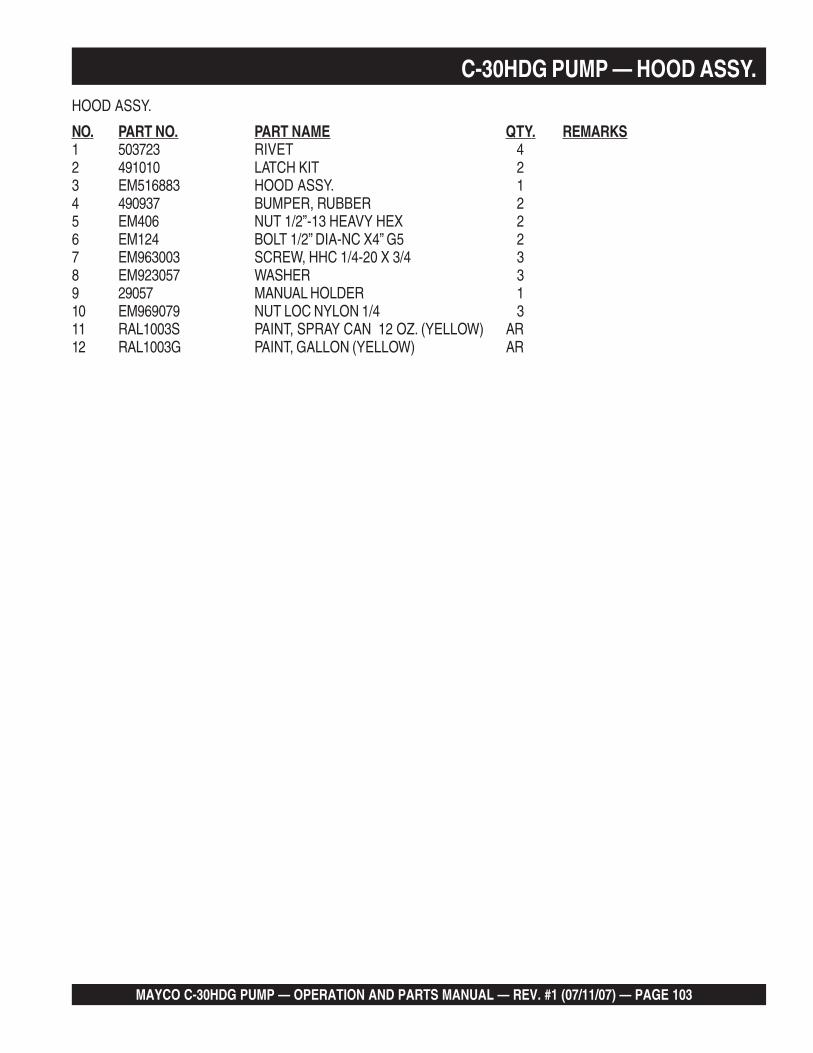
MAYCO C-30HDG PUMP — OPERATION AND PARTS MANUAL — REV. #1 (07/11/07) — PAGE 103
C-30HDG PUMP — HOOD ASSY.HOOD ASSY.
NO. PART NO. PART NAME QTY. REMARKS1 503723 RIVET 42 491010 LATCH KIT 23 EM516883 HOOD ASSY. 14 490937 BUMPER, RUBBER 25 EM406 NUT 1/2”-13 HEAVY HEX 26 EM124 BOLT 1/2” DIA-NC X4” G5 27 EM963003 SCREW, HHC 1/4-20 X 3/4 38 EM923057 WASHER 39 29057 MANUAL HOLDER 110 EM969079 NUT LOC NYLON 1/4 311 RAL1003S PAINT, SPRAY CAN 12 OZ. (YELLOW) AR12 RAL1003G PAINT, GALLON (YELLOW) AR

PAGE 104 — MAYCO C-30HDG PUMP — OPERATION AND PARTS MANUAL — REV. #1 (07/11/07)
C-30HDG PUMP — LUBRICATION PANEL ASSY.
POSITION LOCATION LENGTH OF LINES
1 ....................................................COMPENSATOR ROD ........................................................................ 28"
2 ....................................................COMPENSATOR ROD ........................................................................ 31"
3 ....................................................COMPENSATOR ROD ........................................................................ 28"
4 ....................................................LOWER ROCKER ARM COMPENSATOR ROD ................................. 34"
5 ....................................................LOWER CONNECTING ROD- DRIVE SIDE ........................................ 10"
6 ....................................................LOWER ROCKER ARM - DRIVE SIDE ................................................ 15"
7 ....................................................UPPER ROCKER ARM - COMPENSATOR SIDE ................................ 28"
8 ....................................................UPPER ROCKER ARM - DRIVE SIDE ................................................. 26"
9 ....................................................COUNTER SHAFT BEARING - SPROCKET SIDE .............................. 20"
10 ..................................................COUNTER SHAFT - PULLEY SIDE ..................................................... 20"
11 ..................................................UPPER CONNECTING ROD - DRIVE SIDE ........................................ 40"
12 ..................................................CRANKSHAFT BEARING BLOCK ....................................................... 42"
13 ..................................................CAM BEARING .................................................................................... 42"
14 ..................................................CRANKSHAFT BEARING FLANGE .................................................... 20"
TOTAL LENGTH OF LINES REQUIRED ............................................. 384"
LUBRICATION PANEL ASSY.
Grease daily, two to three shots of #2multi-purpose automotive grease.Over-greasing any bearing will notdamage the machine.
NOTE

MAYCO C-30HDG PUMP — OPERATION AND PARTS MANUAL — REV. #1 (07/11/07) — PAGE 105
LUBRICATION PANEL ASSY.
NO. PART NO. PART NAME QTY. REMARKS1* EM916001 FITTING, GREASE 1/8" NPT 142* EM505489 STRAIGHT FITTING 1/8" NPT 133* 505534 COUPLING W/NUT 1/8' NPT 144* EM505516 PLASTIC HOSE LINE 1/4" DIA. ................ AR......... 1FT=1PC5* EM490531 PROTECTIVE SLEEVE 3/8" (HOSE) ......... AR......... 1FT=1PC6* EM491028 TIE-WRAP 2.5 x 95 MM AR7* EM505490 ADAPTER, 90 DEGREE ELBOW 18 EM512659 KIT, LUBRICATION ........................................ 1 ......... INCLUDES ITEMS W/*
C-30HDG PUMP — LUBRICATION PANEL ASSY.

PAGE 106 — MAYCO C-30HDG PUMP — OPERATION AND PARTS MANUAL — REV. #1 (07/11/07)
C-30HDG PUMP — REMOTE CONTROL CABLE ASSY.
REMOTE CONTROL CABLE ASSY.
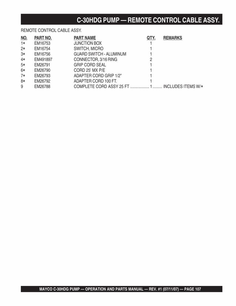
MAYCO C-30HDG PUMP — OPERATION AND PARTS MANUAL — REV. #1 (07/11/07) — PAGE 107
C-30HDG PUMP — REMOTE CONTROL CABLE ASSY.REMOTE CONTROL CABLE ASSY.
NO. PART NO. PART NAME QTY. REMARKS1* EM16753 JUNCTION BOX 12* EM16754 SWITCH, MICRO 13* EM16756 GUARD SWITCH - ALUMINUM 14* EM491897 CONNECTOR, 3/16 RING 25* EM26791 GRIP CORD SEAL 16* EM26790 CORD 25' MX P/E 17* EM26793 ADAPTER CORD GRIP 1/2" 18* EM26792 ADAPTER CORD 100 FT. 19 EM26788 COMPLETE CORD ASSY 25 FT .................. 1......... INCLUDES ITEMS W/*

PAGE 108 — MAYCO C-30HDG PUMP — OPERATION AND PARTS MANUAL — REV. #1 (07/11/07)
Effective: February 22, 2006 TERMS AND CONDITIONS OF SALE — PARTS
PAYMENT TERMS
Terms of payment for parts are net 30 days.
FREIGHT POLICY
All parts orders will be shipped collect orprepaid with the charges added to the invoice.All shipments are F.O.B. point of origin.Multiquip’s responsibility ceases when a signedmanifest has been obtained from the carrier,and any claim for shortage or damage must besettled between the consignee and the carrier.
MINIMUM ORDER
The minimum charge for orders from Mul-tiquip is $15.00 net. Customers will be askedfor instructions regarding handling of ordersnot meeting this requirement.
RETURNED GOODS POLICY
Return shipments will be accepted and creditwill be allowed, subject to the following provi-sions:
1. A Returned Material Authorization mustbe approved by Multiquip prior to ship-ment.
2. To obtain a Return Material Authorization,a list must be provided to Multiquip PartsSales that defines item numbers, quanti-ties, and descriptions of the items to bereturned.
a. The parts numbers and descriptionsmust match the current parts pricelist.
b. The list must be typed or computergenerated.
c. The list must state the reason(s) forthe return.
d. The list must reference the salesorder(s) or invoice(s) under which theitems were originally purchased.
e. The list must include the name andphone number of the person request-ing the RMA.
3. A copy of the Return Material Authoriza-tion must accompany the return shipment.
4. Freight is at the sender’s expense. Allparts must be returned freight prepaid toMultiquip’s designated receiving point.
5. Parts must be in new and resalable con-dition, in the original Multiquip package (ifany), and with Multiquip part numbersclearly marked.
6. The following items are not returnable:
a. Obsolete parts. (If an item is in theprice book and shows as being re-placed by another item, it is obsolete.)
b. Any parts with a limited shelf life(such as gaskets, seals, “O” rings,and other rubber parts) that were pur-chased more than six months prior tothe return date.
c. Any line item with an extended dealernet price of less than $5.00.
d. Special order items.
e. Electrical components.
f. Paint, chemicals, and lubricants.
g. Decals and paper products.
h. Items purchased in kits.
7. The sender will be notified of any materialreceived that is not acceptable.
8. Such material will be held for five workingdays from notification, pending instruc-tions. If a reply is not received within fivedays, the material will be returned to thesender at his expense.
9. Credit on returned parts will be issued atdealer net price at time of the originalpurchase, less a 15% restocking charge.
10. In cases where an item is accepted, forwhich the original purchase documentcan not be determined, the price will bebased on the list price that was effectivetwelve months prior to the RMA date.
11. Credit issued will be applied to futurepurchases only.
PRICING AND REBATES
Prices are subject to change without priornotice. Price changes are effective on a spe-cific date and all orders received on or after thatdate will be billed at the revised price. Rebatesfor price declines and added charges for priceincreases will not be made for stock on handat the time of any price change.
Multiquip reserves the right to quote and selldirect to Government agencies, and to OriginalEquipment Manufacturer accounts who useour products as integral parts of their ownproducts.
SPECIAL EXPEDITING SERVICE
A $35.00 surcharge will be added to the invoicefor special handling including bus shipments,insured parcel post or in cases where Multiquipmust personally deliver the parts to the carrier.
LIMITATIONS OF SELLER’S LIABILITY
Multiquip shall not be liable hereunder fordamages in excess of the purchase price of theitem with respect to which damages areclaimed, and in no event shall Multiquip beliable for loss of profit or good will or for anyother special, consequential or incidental dam-ages.
LIMITATION OF WARRANTIES
No warranties, express or implied, are madein connection with the sale of parts or tradeaccessories nor as to any engine not manufac-tured by Multiquip. Such warranties made inconnection with the sale of new, complete unitsare made exclusively by a statement of war-ranty packaged with such units, and Multiquipneither assumes nor authorizes any person toassume for it any other obligation or liabilitywhatever in connection with the sale of itsproducts. Apart from such written statement ofwarranty, there are no warranties, express,implied or statutory, which extend beyond thedescription of the products on the face hereof.

MAYCO C-30HDG PUMP — OPERATION AND PARTS MANUAL — REV. #1 (07/11/07) — PAGE 109
Mechanical Drive Models
MAYCO PUMP, hereinafter referred to as “Manufacturer’,warrants each new Mayco Pump sold by the manufacturer tobe free from defects in material and workmanship, undernormal use and service, for a period of one year after the dateof delivery to the original retail purchaser. Manufacturer will, atits option, replace or repair at a point designated by theManufacturer any part or parts which shall appear to thesatisfaction of the Manufacturer upon inspection at such pointto have been defective in material or workmanship. Thiswarranty does not obligate the Manufacturer to bear anytransportation charges or labor charges in connection withthe replacement or repair the of the defective parts.
This warranty does not apply to any pump if attempts havebeen made to pump concrete materials which haveseparated, to any pump which has been repaired with otherthan Genuine Mayco Parts, nor to any pump which has beenaltered, repaired or used in such manner as to adversely affectits performance, nor to normal service or maintenance or whereblockages have developed within the pump manifold orplacing line or which has been operated in any other mannernot recommended by the Manufacturer. Due to the abrasivenature of concrete, Mayco does not cover natural componentwear.
THIS WARRANTY AND MANUFACTURER’S OBLIGATIONHEREUNDER, IS IN LIEU OF ALL OTHER WARRANTIES,EXPRESS, IMPLIED OR STATUTORY AND ALL OTHEROBLIGATIONS OR LIABILITIES INCLUDING SPECIAL ORCONSEQUENTIAL DAMAGES OR CONTINGENT LIABILITIESARISING OUT OF THE FAILURE OF ANY PUMP OR PARTTO OPERATE PROPERLY, INCLUDING ANY WARRANTIESOF MERCHANTABILITY OR FITNESS FOR A PARTICULARPURPOSE.
Hydraulic Drive Models
MAYCO PUMP, hereinafter referred to as “Manufacturer”,warrants each new Mayco Pump sold by the manufacturer tobe free from defects in material and workmanship, undernormal use and service, for a period of one year or 2000 hoursafter the date of delivery to the original retail purchaser. TheManufacturer will, at its option, replace or repair at a pointdesignated by Manufacturer any part or parts which shallappear to the satisfaction of Manufacturer upon inspection atsuch point to have been defective in material or workmanship.This warranty does not obligate Manufacturer to bear anytransportation charges or labor charges in connection withthe replacement or repair of the defective parts.
This warranty does not apply to any pump if attempts havebeen made to pump concrete materials which haveseparated, to any pump which has been repaired with otherthan Genuine Mayco Parts, nor to any pump which has beenaltered, repaired or used in such manner as to adversely affectit’s performance, nor to normal service or maintenance orwhere blockages have developed within the pump manifoldor placing line or which has been operated in any other mannernot recommended by the Manufacturer. Due to the abrasivenature of concrete, Mayco does not cover natural componentwear.
THIS WARRANTY AND MANUFACTURER’S OBLIGATIONHEREUNDER, IS IN LIEU OF ALL OTHER WARRANTIES,EXPRESS, IMPLIED OR STATUTORY AND ALL OTHEROBLIGATIONS OR LIABILITIES INCLUDING SPECIAL ORCONSEQUENTIAL DAMAGES OR CONTINGENT LIABILITIESARISING OUT OF THE FAILURE OF ANY PUMP OR PARTTO OPERATE PROPERLY, INCLUDING ANY WARRANTIESOF MERCHANTABILITY OR FITNESS FOR A PARTICULARPURPOSE.
MAYCO PUMP WARRANTY

OPERATION AND PARTS MANUAL
Your Local Dealer is:
HERE'S HOW TO GET HELPPLEASE HAVE THE MODEL AND SERIAL
NUMBER ON-HAND WHEN CALLINGUNITED STATESMultiquip Corporate Office MQ Parts Department18910 Wilmington Ave. Tel. (800) 421-1244 800-427-1244 Fax: 800-672-7877Carson, CA 90746 Fax (800) 537-3927 310-537-3700 Fax: 310-637-3284Contact: [email protected] Parts Warranty Department800-306-2926 Fax: 800-672-7877 800-421-1244, Ext. 279 Fax: 310-537-1173310-537-3700 Fax: 310-637-3284 310-537-3700, Ext. 279Service Department Technial Assistance800-421-1244 Fax: 310-537-4259 800-478-1244 Fax: 310-631-5032310-537-3700
MEXICO UNITED KINGDOMMQ Cipsa Multiquip (UK) Limited Head OfficeCarr. Fed. Mexico-Puebla KM 126.5 Tel. (52) 222-225-9900 Hanover Mill, Fitzroy Street, Tel. 0161 339 2223Momoxpan, Cholula, Puebla 72760 Mexico Fax (52) 222-285-0420 Ashton-under-Lyne, Fax 0161 339 3226Contact: [email protected] Lancashire OL7 0TL
Contact: [email protected]
CANADA BRAZILMultiquip Multiquip4110 Industriel Boul. Tel. (450) 625-2244 Av. Evandro Lins e Silva, 840 - grupo 505 Tel. 011-55-21-3433-9055Laval, Quebec, Canada H7L 6V3 Fax (450) 625-8664 Barra de Tijuca - Rio de Janeiro Fax 011-55-21-3433-9055Contact: [email protected] Contact: [email protected], [email protected]
© COPYRIGHT 2007, MULTIQUIP INC.
Multiquip Inc, the MQ logo and the Mayco logo are registered trademarks of Multiquip Inc. and may not be used, reproduced, or altered without written permission. All othertrademarks are the property of their respective owners and used with permission.
This manual MUST accompany the equipment at all times. This manual is considered a permanent part of the equipment and should remain with the unit if resold.
The information and specifications included in this publication were in effect at the time of approval for printing. Illustrations, descriptions, references and technical datacontained in this manual are for guidance only and may not be considered as binding. Multiquip Inc. reserves the right to discontinue or change specifications, design orthe information published in this publication at any time without notice and without incurring any obligations.