Concrete Filled Tubular Bracing Subjected to Cyclic Loading · PDF filesuggested that CFST...
13
Civil Engineering Infrastructures Journal, 50(1): 165 – 177, June 2017 Print ISSN: 2322-2093; Online ISSN: 2423-6691 DOI: 10.7508/ceij.2017.01.010 Technical Note Concrete Filled Tubular Bracing Subjected to Cyclic Loading Saneei Nia, Z. 1 , Ghassemieh, M. 2* and Baei, M. 3 1 Ph.D., School of Civil Engineering, College of Engineering, University of Tehran, Tehran, Iran. 2 Professor, School of Civil Engineering, College of Engineering, University of Tehran, Tehran, Iran. 3 M.Sc., School of Civil Engineering, College of Engineering, University of Tehran, Tehran, Iran. Received: 20 Apr. 2016; Revised: 08 Jan. 2017; Accepted: 16 Jan. 2017 ABSTRACT: The energy absorption of concrete filled, hollow-steel bracing was analyzed respect to geometric and mechanical parameters including the width-to-thickness section ratio, slenderness level, and strength of the steel and concrete. Local buckling and ductility were also investigated with respect to variation in the cross-section. The infill increased the compression resistance, even after multiple, inelastic load reversals. This resulted in improved ductility capacity by limiting local buckling and in some cases preventing the local buckling. The energy absorption of such braces is appraised with respect to earthquake design presented in different international standards. The overall system effectiveness was assessed by comparing infilled bracing to an existing state-of-the-art, buckling restraint bracing system. The results showed the energy dissipation in buckling restraint bracing systems is more of in comparison with tubular bracing system designed by European and American codes in higher cycles. Keywords: Buckling Restraint Brace, Composite Bracing System, Cyclic Loading, Ductility, Energy Absorption. INTRODUCTION In seismic regions, cold-formed, rectangular tubing has been used widely for bracing of steel frame structures due to their simplicity and lower cost of fabrications, and with such systems, in general, the hollow steel bracing exhibits stable, hysteretic behavior up to the on-set of local buckling, and then shows considerable degradation in strength and ductility depending on slenderness. The presence of concrete infill improves the compression resistance of the hollow section steel braces, even after multiple inelastic load reversals. Numerous studies have been conducted on the response of concrete filled, rectangular tubular sections stub columns. The results showed that the filler material improves the failure load several times even after multiple inelastic load reversals. Furthermore, concrete filled steel box specimens under * Corresponding author E-mail: [email protected] 165
Transcript of Concrete Filled Tubular Bracing Subjected to Cyclic Loading · PDF filesuggested that CFST...
Civil Engineering Infrastructures Journal, 50(1): 165 – 177, June 2017 Print ISSN: 2322-2093; Online ISSN: 2423-6691 DOI: 10.7508/ceij.2017.01.010
Technical Note
Concrete Filled Tubular Bracing Subjected to Cyclic Loading
Saneei Nia, Z.1 , Ghassemieh, M.2* and Baei, M.3
1 Ph.D., School of Civil Engineering, College of Engineering, University of Tehran,
Tehran, Iran. 2 Professor, School of Civil Engineering, College of Engineering, University of Tehran,
Tehran, Iran. 3 M.Sc., School of Civil Engineering, College of Engineering, University of Tehran,
Tehran, Iran.
Received: 20 Apr. 2016; Revised: 08 Jan. 2017; Accepted: 16 Jan. 2017 ABSTRACT: The energy absorption of concrete filled, hollow-steel bracing was analyzed respect to geometric and mechanical parameters including the width-to-thickness section ratio, slenderness level, and strength of the steel and concrete. Local buckling and ductility were also investigated with respect to variation in the cross-section. The infill increased the compression resistance, even after multiple, inelastic load reversals. This resulted in improved ductility capacity by limiting local buckling and in some cases preventing the local buckling. The energy absorption of such braces is appraised with respect to earthquake design presented in different international standards. The overall system effectiveness was assessed by comparing infilled bracing to an existing state-of-the-art, buckling restraint bracing system. The results showed the energy dissipation in buckling restraint bracing systems is more of in comparison with tubular bracing system designed by European and American codes in higher cycles. Keywords: Buckling Restraint Brace, Composite Bracing System, Cyclic Loading, Ductility, Energy Absorption.
INTRODUCTION In seismic regions, cold-formed, rectangular tubing has been used widely for bracing of steel frame structures due to their simplicity and lower cost of fabrications, and with such systems, in general, the hollow steel bracing exhibits stable, hysteretic behavior up to the on-set of local buckling, and then shows considerable degradation in strength and ductility depending on slenderness. The
presence of concrete infill improves the compression resistance of the hollow section steel braces, even after multiple inelastic load reversals.
Numerous studies have been conducted on the response of concrete filled, rectangular tubular sections stub columns. The results showed that the filler material improves the failure load several times even after multiple inelastic load reversals. Furthermore, concrete filled steel box specimens under
* Corresponding author E-mail: [email protected] 165
Saneei Nia, Z. et al.
constant axial force and cyclic lateral loading showed generally noticeable earthquake resistance characteristics undergoing the inelastic action. Tort and Hajjar (2002) studied the local damage progression in concrete filled steel tubes beam-columns and connections in composite frames. Local damage was quantified through the development of damage indices based upon results obtained from experiments. A fiber based Finite Element formulation was also introduced for assessing global capacity and seismic demand. The proposed displacement and energy-based damage functions provided an efficient way to quantify the capacity of rectangular concrete filled steel tube members. Liang et al. (2005), in a numerical work, presented a nonlinear, fiber analysis method for predicting the ultimate strengths and behavior of short concrete filled, thin-walled steel box columns with local buckling effects. The progressive local and post-local buckling were simulated by gradually redistributing the normal stresses within the steel plates. The study compared the effects of steel and concrete strength on ultimate strength and ductility of concrete filled steel tubular (CFST) columns by using the concept of the effective width of members. The results suggested that CFST columns should be designed to have a section performance index as high as 0.5 to be considered as efficient composite sections. In an experimental program of hollow versus concrete filled steel members subjected to monotonic and cyclic axial loading, Broderick et al. (2005) demonstrated that the presence of the concrete infill influences the failure mode, as well as their compression and tension load responses. Dicleli and Calik (2008) developed a nonlinear structural model to simulate the cyclic axial force deformation behavior of steel braces with box sections including their buckling behavior. The nonlinear brace structural model was then used to study the effect of various ground
motion and structural parameters on the seismic response of single story, single bay concentrically braced frames with chevron braces. In a study done by Goto et al. (2010) a Finite Element model was introduced in order to fully include the important factors such as cyclic local buckling of steel tube, nonlinear behavior of confined concrete, and interface action between steel tube and in-filled concrete. The proposed model was validated by comparing with the results of cyclic loading experiments on CFT columns with the Finite Element results.
More recently, a comparison between design evaluations of flexural strength of concrete filled steel tubular columns was examined by Beheshti-Aval (2012). The results showed that the comparison of analytical results and codes indicates that the accuracy of ACI method in estimation of axial-flexural strength of concrete filled tube (CFT) columns is appropriate than AISC-LRFD. Denavit and Hajjar (2012) assessed the circular concrete filled steel tubes subjected to seismic and extreme loading. In that research, a three-dimensional distributed plasticity beam element formulation for circular concrete filled steel tubes was developed for nonlinear static and dynamic analyses of composite seismic force resisting systems. The formulation utilizes uniaxial cyclic constitutive models for the concrete core and steel tube that account for the salient features of each material, as well as the interaction between the two, including concrete confinement and local buckling of the steel tube. The accuracy of the formulation was verified against a wide variety of experimental results. Study by Han et al. (2014) reviewed the development of the family of concrete filled steel tubular structures and the design approaches from various countries and particularly in China were examined briefly.
Cai et al. (2015) investigated the mechanical behaviors and failure mechanism
166
Civil Engineering Infrastructures Journal, 50(1): 165 – 177, June 2017
of steel reinforced concrete filled steel tubular (SRCFST) columns with the software of ABAQUS/standard solver. The model in Eurocode 3 significantly underestimated the load bearing capacity of SRCFST columns, and a new model was then proposed to predict the strength of the SRCFST columns. Based on the comparison between the calculation results from the proposed model and experimental results, the proposed model can provide reliable prediction of the ultimate load carrying capacity for the SRCFST columns. Li et al. (2015) explored the performance of concrete filled steel tubes subjected to eccentric tension both experimentally and numerically. Their results showed current design equations provide safe and conservative predictions on the tensile and flexural strength of eccentrically loaded CFST tensile members. Patel et al. (2015) conducted an investigation on biaxially loaded high strength rectangular CFST slender beam-columns with large depth-to-thickness ratios, which may undergo local and global interaction buckling, have received very little attention. Comparisons of computer solutions with existing experimental results were made to examine the accuracy of the multi-scale numerical model. Numerical results presented a better understanding of the local and global interaction buckling behavior of high strength thin-walled CFST slender beam-columns.
Skalomenos et al. (2015) studied the seismic behavior of plane moment-resisting frames (MRFs) consisting of I steel beams and CFT columns. More specifically, the effect of modeling details of each individual component of CFT-MRFs, such as the composite CFT columns, the beam-column connections, the panel zones, and the steel I beams on their seismic behavior, were studied through comparisons against available experimental results. Another study was done by Skalomenos et al. (2016) on the
CFT columns using ultrahigh strength Steel. To further improve the seismic performance of these columns, an experimental investigation was conducted into CFT columns using ultrahigh strength steel. They concluded that in comparison with the conventional steel specimens, larger elastic deformation, higher strength, and delay of local buckling were observed in the high-strength steel specimens, while compared with the circular specimens, the square specimens sustained larger drift angles without fracture of their steel tubes because of the development and progress of serious local buckling. Furthermore, a simple analytical model based on the concept of the superposed strength method was proposed. Zhou et al. (2016) presented an experimental study on the mechanical behavior, particularly the tensile stiffness, of SCFTs under axial tension, from both the force/displacement-level and strain-level perspectives. It was observed that the tensile stiffness of SCFTs could be underestimated if the SCFTs under tension are simply treated as equal to the hollow tubes by neglecting the concrete-to-steel tube confinement and tension stiffening effect; this underestimation may cause non-conservative inaccuracies in calculating the component internal forces, structural natural frequencies, and seismic effects in the design and analysis of structures.
Till now, not very accurate and detailed numerical research has been conducted on the versatile Finite Element model analysis that can take into account all the relevant parameters of thin walled concrete filled tubular braces subjected to cyclic loading. Therefore, the aim of this research is to analyze the improvement gained by introducing concrete into a hollow bracing system, using a nonlinear fiber element analysis technique. The accuracy of the fiber element method first is established by
167
Saneei Nia, Z. et al.
comparison with the experimental results. Then after the effect of width to thickness ratio, slenderness ratio and mechanical properties of concrete and steel on the energy dissipation of system examined. The role of key parameters in the design of the bracing system using different design codes of practice (Eurocode 3, 2009; AISC, 2010; AIJ, 2001) is provided. To show the quality of the composite bracing system, the behavior of this type of bracing system has been compared with the behavior of the buckling restraint bracing system (BRB) which comes about to be as an effective and an efficient state of the art seismic resisting system. Furthermore, despite significant body of works have done before the exact extent of energy dissipation in composite tubular sections remains unknown. The paper in part focused on the energy absorption of infill composite bracing system and employing the evaluation of dissipated energy to amend the behavior of brace system.
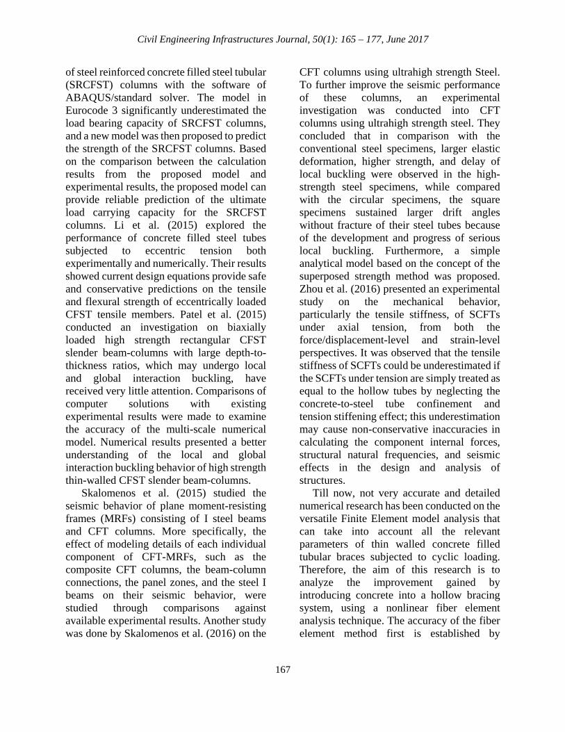
NUMERICAL MODELING A length of square steel tubes will be numerically model with and without concrete infill. In numerical modeling using OpenSees open access computer program, the inelastic beam-column element with small deformation theory used herein relies on the co-rotational theory to represent the moderate to large deformation effect of inelastic buckling of the composite brace (Mazzoni et al., 2007). To this end, the composite section of bracing system needs to be subdivided in to at least two elements; a) Steel square hollow section and b) Concrete core. Square hollow section is discretized into three fibers in horizontal and ten fibers in vertical direction. Also concrete core is discretized into ten fibers in two different directions; as illustrated in Figure 1.
Stress resultants are normally obtained by numerical integration of the stresses through the composite section. The fiber stresses for the steels with residual stresses is expressed by Eq. (1).
𝜀𝜀𝑠𝑠 =𝜎𝜎𝑠𝑠𝐸𝐸𝑠𝑠�1 +
37
(σsσ0.7
)𝑛𝑛� (1)
where σs is the longitudinal stress, εs is the longitudinal strain, Es is the Young’s modulus, σ0.7 is the stress corresponding to E0.7 = 0.7Es and n is the knee factor that defines the sharpness of the stress-strain curve. The knee factor (n) was selected equal to 25 to account for the isotropic strain hardening. The confinement effect is assumed only to increase the ductility of the encased concrete and not change the ultimate load. The linear part of the concrete stress-strain curve is modeled using the Eq. (2).
𝜎𝜎𝑐𝑐 =𝑓𝑓𝑐𝑐′𝛾𝛾 (𝜀𝜀𝑠𝑠/𝜀𝜀𝑐𝑐
′ )𝛾𝛾 − 1 + ( 𝜀𝜀𝑠𝑠/𝜀𝜀𝑐𝑐′)𝛾𝛾
(2)
where σc is the longitudinal compressive stress, f'c is the compressive cylinder strength, εc is the longitudinal compressive strain, and ε'c is the strain at f'c. The parameter γ is determined by Eq. (3).
𝛾𝛾 =𝐸𝐸𝑐𝑐
𝐸𝐸𝑐𝑐 − (𝑓𝑓𝑐𝑐′/𝜀𝜀𝑐𝑐′) (3)
where Ec is the Young’s modulus. The strain ε'c is taken as 0.002 for concrete of strength under 28 MPa and 0.003 for concrete strength over 82 MPa. It is determined as a linear function of the concrete strength between 28 and 82 MPa. The other parts of the stress-strain curve for confined concrete are defined as:
168
Civil Engineering Infrastructures Journal, 50(1): 165 – 177, June 2017
Fig. 1. Geometry and loading for numerical study; a) Composite section; b) Loading; c) Displacement history
𝜎𝜎𝑐𝑐 = 𝑓𝑓𝑐𝑐′ 𝑓𝑓𝑓𝑓𝑓𝑓 𝜀𝜀𝑐𝑐′ < 𝜀𝜀𝑐𝑐 ≤ 0.005 (4) 𝜎𝜎𝑐𝑐 = 𝛼𝛼𝑓𝑓𝑐𝑐′ + 100(0.015 − 𝜀𝜀𝑐𝑐)(𝑓𝑓𝑐𝑐′ − 𝛼𝛼𝑓𝑓𝑐𝑐′) 𝑓𝑓𝑓𝑓𝑓𝑓 0.005 < 𝜀𝜀𝑐𝑐 < 0.015
(5)
𝜎𝜎𝑐𝑐 = 𝛼𝛼𝑓𝑓𝑐𝑐′ 𝑓𝑓𝑓𝑓𝑓𝑓 𝜀𝜀𝑐𝑐 > 0.015 (6)
where α is taken as 1.0, when the width-to-thickness ratio (b/t) of the composite brace is less than 24 and is taken as 0.0 when the b/t ratio is greater than 64. For width-to-thickness ratios between 24 and 64, α is taken as 0.6. Model Validation
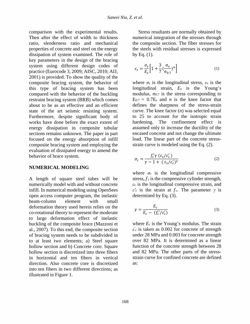
The numerical model was validated against experimental tests conducted by Broderick et al. (2005). The square hollow sections with cross section of 20×20×2 mm manufactured from cold formed steel (S235JRH), with nominal yield strength of 235 MPa, was selected for verification purposes. The compressive and tensile strengths of the concrete were 24 MPa and 2.53 MPa, respectively. The length of test specimen was 1100 mm with fixed end restraints. In the cyclic tests, loading was applied in accordance with the provisions of the Eurocode 3 (2009). The cyclic responses from the experimental, as well as fiber analysis, are shown in Figure 2; in which the load values were normalized by the yield capacity of the section (fyAs).
The results indicate that the numerical model simulated the behavior very closely to that of the experiment. The maximum value of (F/fyAs) which presents the ratio of the force to nominal strength of the section was 1.3 in the experimental model and 1.28 in the numerical. The maximum experimental axial displacement was approximately 30 mm and the numerical value was 27 mm.
A snap through model was used for bracing system with fixed end conditions. The model consists of two force based, beam column element with 1/1000 of its length of initial imperfection, through the member. Five integration points are considered along the element to account for distributed plasticity, are defined through the use of fiber discretization.
In the numerical model, the stress-strain diagram used for steel is Giuffre-Menegotto-Pinto model is used for the stress- strain diagram of the steel with isotropic strain hardening in which a transition curve is defined in order to avoid the unsmooth response of bilinear kinematic hardening behavior in yielding point. Consequently; in which path-dependent nature of the material can be traced effectively. Also the Bauschinger effect is defined in the material stress-strain curve so that strength weakening in element behavior is automatically
169
Saneei Nia, Z. et al.
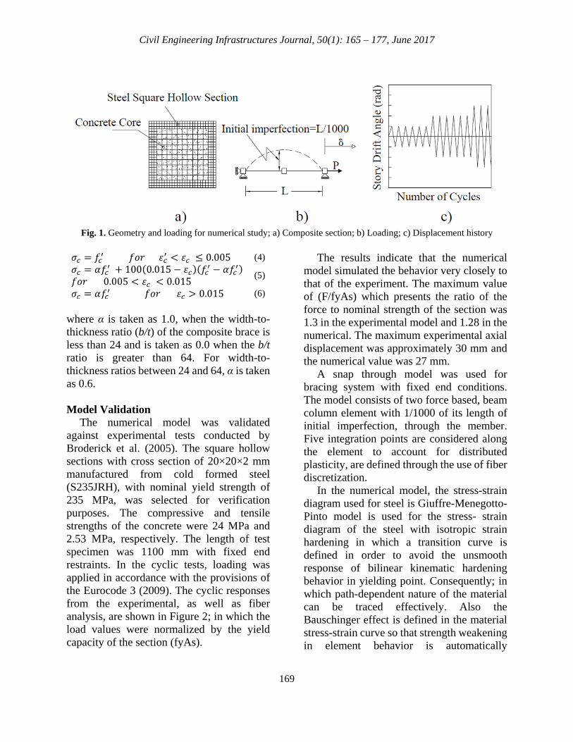
modeled. Three different steel materials were used to model the tube: A36 carbon, A440 high strength, and A514 heated-treated structural alloy. Their mechanical properties
are summarized in Table 1. The average concrete compressive strengths were selected as 21 MPa, 28 MPa, and 35 MPa (Table 2).
(a) Experimental (Broderick et al., 2005) (b) Numerical
Fig. 2. The experimental load-displacement response of specimen 20×20×2 mm
Table 1. Mechanical properties of the steel material used in this study Steel Types E
(GPa) Fy
(MPa) Fu
(MPa) Ultimate Strain % Fu/Fy Types Specification
1 (Low strength) Carbon steel: A36 200 240 375 20 1.56
2 (Mid strength) High strength, Low alloy carbon; A440, A441, A514 200 346 470 17 1.36
3 (High strength) Heated treated structural alloy steels; A514 200 692 762 7 1.1
Table 2. Mechanical properties of the concrete material used in this study
Concrete Type Compressive Strength (MPa)
Ultimate Strength (MPa)
Compressive Strain Ultimate Strain
1 21 15 0.002 0.004 2 28 12 0.002 0.004 3 35 15 0.002 0.0035
Table 3. Geometric properties of the numerical specimens
Specimen No.
Tube Height (mm)
Tube Width (mm)
Tube Thickness
(mm)
Area of Steel Section
(mm2)
Width to Thickness
Ratio
Slenderness Ratio
L = 3000 mm L = 6000 mm
1 80 80 6 1776 11.3 99.3 198.6 2 80 80 8 2304 8.0 102.1 204.1 3 100 100 6 2256 14.7 78.2 156.4 4 100 100 8 2944 10.5 79.9 159.7 5 100 100 10 3600 8.0 81.6 163.3 6 120 120 6 2736 18.0 64.5 128.9 7 120 120 8 3584 13.0 65.6 131.2 8 120 120 10 4400 10.0 66.8 133.6 9 150 150 8 4544 16.8 51.7 103.5 10 150 150 10 5600 13.0 52.5 105.0 11 150 150 15 8100 8.0 54.4 108.9 12 200 200 12 9024 14.7 39.1 78.2 13 200 200 15 11100 11.3 39.7 79.4
170
Civil Engineering Infrastructures Journal, 50(1): 165 – 177, June 2017
To cover the broad range of the tubular sections, 13 numerical models of 3,000 mm or 6,000 mm were employed in this study (Table 3). All were comprised of square, hollow section and all were subjected to cyclic, axial displacement of increasing amplitude in accordance with the provisions of the SAC (Krawinkler et al., 2000). The numerical models spanned various cross sections, slenderness ratios and width-to-thickness ratios. NUMERICAL RESULTS Once the numerical model was calibrated, the width to thickness ratio, slenderness ratio, and material properties were checked for their influence on energy absorption. Width to Thickness Ratio (wttr)
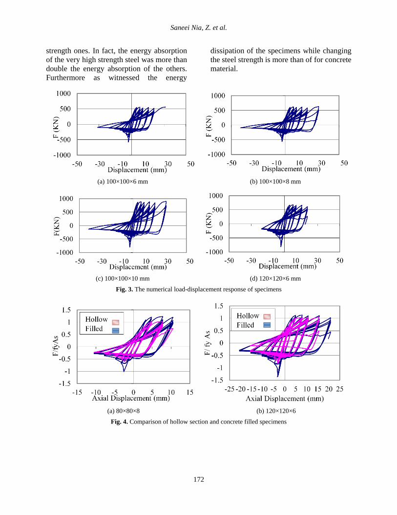
The hysteresis curves were generated in Figure 3 using A36 steel and with compression strength of 28 MPa for the concrete and the beam length was considered 3,000 mm.
As illustrated in Figure 3, when the area of steel section increased, the hysteresis behavior is improved. To investigate the effects of concrete infill on wttr; as shown in specimen 100×100×10 (Figure 3c), which has a minimum width-to-thickness ratio equal to 8, the hysteresis diagram has the broadest curves among the specimens. When wttr decreased the effects of the concrete were more prominent. The 80×80×8 specimen (with lowest wttr = 8) and 120×120×6 specimen (with highest wttr = 18) are compared in terms of normalized force versus axial displacement and energy dissipations in Figures 4 and 5. As the normalized axial force increased by 20% in the 80×80×8 specimens and increased by 10% in the 120×120×6 specimens. This clearly demonstrates that the concrete infill effect more on the specimen with lower wttr.
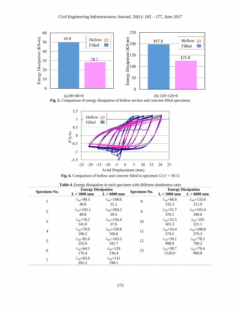
As expected, with lower wttr, the filled specimens performed better than the hollow ones, especially in delaying local buckling and improving energy absorption and ductility. Figure 5 displays improvements in energy dissipation. As shown in Figure 5 improvements in energy dissipation in first specimen reaches to 75%; where, this value in specimen 6 reaches 57% and, therefore, infill concrete influences better with low wttr.
Slenderness Ratio
To study the influence of the slenderness ratio parameter (), each specimen modeled by A36 steel and compression strength of 28 MPa for the concrete with two different length, (3,000 m and 6,000 mm). The results showed that specimens with the lower slenderness ratio had a lower probability of buckling. Lower slenderness ratio, decreased the impact of the infill. In fact, in specimen 12 with the lowest slenderness ratio ( = 39.1), the infill only increase the normalized axial strength by 5% (see Figure 6).
Table 4 shows the energy dissipation in each specimen. For most cases the energy dissipation increased as the slenderness ratio decreased. However, specimens 3 and 4 have almost the same slenderness ratio, but in specimen 4 the energy dissipation is higher than specimen 3 because of its lower wttr. The same is true with specimens 12 and 13. Material Properties
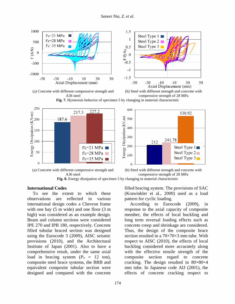
Numerical investigation implemented in order to investigate the effect of concrete compressive strength and also steel strength as shown in Figures 7 and 8. The changes in the concrete strength from 21 MPa and 35 MPa had little effect on the deterioration of cyclic peak compression forces, but increased the cyclic peak compressive force and dissipated slightly more energy.
Also, results showed higher strength steel (Type 3) dissipates more energy than lower
171
Saneei Nia, Z. et al.
strength ones. In fact, the energy absorption of the very high strength steel was more than double the energy absorption of the others. Furthermore as witnessed the energy
dissipation of the specimens while changing the steel strength is more than of for concrete material.
(a) 100×100×6 mm (b) 100×100×8 mm
(c) 100×100×10 mm (d) 120×120×6 mm
Fig. 3. The numerical load-displacement response of specimens
(a) 80×80×8 (b) 120×120×6
Fig. 4. Comparison of hollow section and concrete filled specimens
172
Civil Engineering Infrastructures Journal, 50(1): 165 – 177, June 2017
(a) 80×80×8 (b) 120×120×6
Fig. 5. Comparison of energy dissipation of hollow section and concrete filled specimens
Fig. 6. Comparison of hollow and concrete filled in specimen 12 ( = 39.1)
Table 4. Energy dissipation in each specimen with different slenderness ratio
Specimen No. Energy Dissipation Specimen No. Energy Dissipation L = 3000 mm L = 6000 mm L = 3000 mm L = 6000 mm
1 3m=99.3 6m=198.6 8 3m=66.8 6m=133.6 38.8 31.1 316.3 211.9
2 3m=102.1 6m=204.2 9 3m=51.7 6m=103.4 49.8 39.5 370.1 189.6
3 3m=78.2 6m=156.4 10 3m=52.5 6m=105 141.0 37.6 501.3 221.1
4 3m=79.9 6m=159.8 11 3m=54.4 6m=108.8 196.2 106.6 574.5 270.3
5 3m=81.6 6m=163.2 12 3m=39.1 6m=78.2 255.9 191.7 998.9 790.2
6 3m=64.5 6m=129 13 3m=39.7 6m=79.4 176.4 136.4 1126.0 960.8
7 3m=65.6 6m=131 261.2 198.1
173
Saneei Nia, Z. et al.
(a) Concrete with different compressive strength and A36 steel
(b) Steel with different strength and concrete with compressive strength of 28 MPa
Fig. 7. Hysteresis behavior of specimen 5 by changing in material characteristic
(a) Concrete with different compressive strength and
A36 steel (b) Steel with different strength and concrete with
compressive strength of 28 MPa Fig. 8. Energy dissipation of specimen 5 by changing in material characteristic
International Codes
To see the extent to which these observations are reflected in various international design codes a Chevron frame with one bay (5 m wide) and one floor (3 m high) was considered as an example design. Beam and column sections were considered IPE 270 and IPB 180, respectively. Concrete filled tubular braced section was designed using the Eurocode 3 (2009), AISC seismic provisions (2010), and the Architectural Institute of Japan (2001). Also to have a comprehensive result, under the same axial load in bracing system (Pu = 12 ton), composite steel brace systems, the BRB and equivalent composite tubular section were designed and compared with the concrete
filled bracing system. The provisions of SAC (Krawinkler et al., 2000) used as a load pattern for cyclic loading.
According to Eurocode (2009), in response to the axial capacity of composite member, the effects of local buckling and long term reversal loading effects such as concrete creep and shrinkage are considered. Thus, the design of the composite brace section resulted in a 70×70×3 mm tube. With respect to AISC (2010), the effects of local buckling considered more accurately along with the effective tensile strength of the composite section regard to concrete cracking. The design resulted in 80×80×4 mm tube. In Japanese code AIJ (2001), the effects of concrete cracking respect to
174
Civil Engineering Infrastructures Journal, 50(1): 165 – 177, June 2017
compressive loading considered. Therefore, under compressive axial loading, because of concrete cracking, the capacity of the composite bracing system is decreased. Thus, with AIJ (2001) code the composite brace section turns out to be 120×120×8 mm tube.
Another structural steel element that offers strength and energy dissipation while at the same time exhibiting well distributed yielding is the buckling restrained brace system (BRB) (Black et al., 2002). Hence, in order to compare bracing systems with BRB as a state of the art bracing system in dissipating energy, the BRB is also designed. Based on the similar required demand of the chevron frame structure, the steel core of the BRB is designed to be 80×10 mm, resulting 800 mm2 of steel area. As a final point, for comparison purposes, based on equivalent steel area of the BRB section, an equivalent practical tubular composite section of 75×75×3 mm can be estimated. The summary of all the sections designed by different codes are illustrated in Table 5.
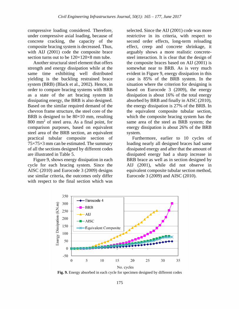
Figure 9, shows energy dissipation in each cycle for each bracing system. Since the AISC (2010) and Eurocode 3 (2009) designs use similar criteria, the outcomes only differ with respect to the final section which was
selected. Since the AIJ (2001) code was more restrictive in its criteria, with respect to second order effects, long-term reloading effect, creep and concrete shrinkage, it arguably shows a more realistic concrete-steel interaction. It is clear that the design of the composite braces based on AIJ (2001) is somewhat near to BRB. As is very much evident in Figure 9, energy dissipation in this case is 85% of the BRB system. In the situation where the criterion for designing is based on Eurocode 3 (2009), the energy dissipation is about 16% of the total energy absorbed by BRB and finally in AISC (2010), the energy dissipation is 27% of the BRB. In the equivalent composite tubular section, which the composite bracing system has the same area of the steel as BRB system; the energy dissipation is about 26% of the BRB system.
Furthermore, earlier to 10 cycles of loading nearly all designed braces had same dissipated energy and after that the amount of dissipated energy had a sharp increase in BRB brace as well as in section designed by AIJ (2001), while did not observe in equivalent composite tubular section method, Eurocode 3 (2009) and AISC (2010).
Fig. 9. Energy absorbed in each cycle for specimen designed by different codes
175
Saneei Nia, Z. et al.
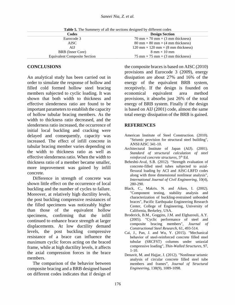
Table 5. The Summery of all the sections designed by different codes Codes Design Section
Eurocode 3 70 mm × 70 mm × (3 mm thickness) AISC 80 mm × 80 mm × (4 mm thickness) AIJ 120 mm × 120 mm × (8 mm thickness)
BRB (Inner Core) 8 mm × 10 mm Equivalent Composite Section 75 mm × 75 mm × (3 mm thickness)
CONCLUSIONS An analytical study has been carried out in order to simulate the response of hollow and filled cold formed hollow steel bracing members subjected to cyclic loading. It was shown that both width to thickness and effective slenderness ratio are found to be important parameters to establish the capacity of hollow tubular bracing members. As the width to thickness ratio decreased, and the slenderness ratio increased, the occurrence of initial local buckling and cracking were delayed and consequently, capacity was increased. The effect of infill concrete in tubular bracing member varies depending on the width to thickness ratio as well as effective slenderness ratio. When the width to thickness ratio of a member became smaller, more improvement was gained by infill concrete.
Difference in strength of concrete was shown little effect on the occurrence of local buckling and the number of cycles to failure. Moreover, at relatively high ductility levels, the post buckling compressive resistances of the filled specimens was noticeably higher than those of the equivalent hollow specimens, confirming that the infill continued to enhance brace strength at larger displacements. At low ductility demand levels, the post buckling compressive resistance of a brace can influence the maximum cyclic forces acting on the braced frame, while at high ductility levels, it affects the axial compression forces in the brace members.
The comparison of the behavior between composite bracing and a BRB designed based on different codes indicates that if design of
the composite braces is based on AISC (2010) provisions and Eurocode 3 (2009), energy dissipation are about 27% and 16% of the energy of the equivalent BRB system, receptively. If the design is founded on economical equivalent area method provisions, it absorbs just 26% of the total energy of BRB system. Finally if the design is based on AIJ (2001) code, almost the same total energy dissipation of the BRB is gained.
REFERENCES American Institute of Steel Construction. (2010).
"Seismic provision for structural steel building", ANSI/AISC 341-10.
Architectural Institute of Japan (AIJ). (2001). Standard of structural calculation of steel reinforced concrete structures, 5th Ed.
Beheshti-Aval, S.B. (2012). “Strength evaluation of concrete-filled steel tubes subjected to axial-flexural loading by ACI and AISC-LRFD codes along with three dimensional nonlinear analysis”, International Journal of Civil Engineering, 10(4), 280-290.
Black, C., Makris. N. and Aiken, I. (2002). "Component testing, stability analysis and characterization of buckling-restrained unbonded braces", Pacific Earthquake Engineering Research Center, College of Engineering, University of California, Berkeley, USA.
Broderick, B.M., Goggins, J.M. and Elghazouli, A.Y. (2005). "Cyclic performance of steel and composite bracing members", Journal of Constructional Steel Research, 61, 493-514.
Cai, J., Pan, J. and Wu, Y. (2015). "Mechanical behavior of steel-reinforced concrete filled steel tubular (SRCFST) columns under uniaxial compressive loading", Thin-Walled Structures, 97, 1-10.
Denavit, M. and Hajjar, J. (2012). "Nonlinear seismic analysis of circular concrete filled steel tube members and frames”, Journal of Structural Engineering, 138(9), 1089-1098.
176
Civil Engineering Infrastructures Journal, 50(1): 165 – 177, June 2017
Dicleli, M. and Calik, E.E. (2008). “Physical theory hysteretic model for steel braces”, Journal of Structural Engineering, 134(7), 1215-1228.
Eurocode 3. (2009). “Design of steel and concrete structures, Part 1.1, General rules and rules for buildings”, EN1993-1-1, European Committee for Standardization.
Goto, Y., Kumar, G. and Kawanishi, M. (2010). "Nonlinear Finite-Element analysis for hysteretic behavior of thin-walled circular steel columns with in-filled concrete”, Journal of Structural Engineering, 136(11), 1413-1422.
Han, L.H., Li, W. and Bjorhovde, R. (2014). "Developments and advanced applications of concrete-filled steel tubular (CFST) structures: Members", Journal of Constructional Steel Research, 100, 211-228.
Krawinkler, H., Gupta, A., Medina, R. and Luco, N. (2000). "Loading histories for seismic performance testing of SMRF components and assemblies", Report No. SAC/BD-00/10, SAC Joint Venture, Sacramento, California, USA.
Li, W., Han, L.H. and Chan, T.M. (2015). "Performance of concrete filled steel tubes subjected to eccentric tension", Journal of Structural Engineering, 141(12), 04015049-9.
Liang, Q.Q, Uy, B. and Liew, J.Y.R (2005). "Nonlinear analysis of concrete filled thin-walled steel box columns with local buckling effects", Journal of Constructional Steel Research, 62, 581-591.
Mazzoni, S., Mckenna, F., Scott, M.H. and Fenves, G.L. (2007). "Open system for earthquake engineering simulation (OpenSees) command language manual", University of California, USA.
Patel, V.I., Liang, Q.Q. and Hadi, M.N. (2015). "Biaxially loaded high-strength concrete filled steel tubular slender beam-columns, Part II: Parametric study", Journal of Constructional Steel Research, 110, 200-207.
Skalomenos, K.A., Hatzigeorgiou, G.D. and Beskos, D.E. (2015). "Modeling level selection for seismic analysis of concrete filled steel tube/moment-resisting frames by using fragility curves", Earthquake Engineering & Structural Dynamics, 44(2), 199-220.
Skalomenos, K.A., Hayashi, K., Nishi, R., Inamasu, H. and Nakashima, M. (2016). "Experimental behavior of concrete filled steel tube columns using ultrahigh-strength steel", Journal of Structural Engineering, 142(9), 04016057-13.
Tort, C. and Hajjar, J.F. (2002). "Capacity assessment of rectangular concrete filled steel tube (RCFT) members and connections for performance-based
design of composite frames", Department of Civil Engineering, University of Minnesota, USA.
Zhou, M., Fan, J.S., Tao, M.X. and Nie, J.G. (2016). "Experimental study on the tensile behavior of square concrete filled steel tubes", Journal of Constructional Steel Research, 121, 202-215.
177