Nonlinear Inelastic Analysis of Concrete-Filled Steel ...vuir.vu.edu.au/22015/1/Vipulkumar...
308
Nonlinear Inelastic Analysis of Concrete-Filled Steel Tubular Slender Beam-Columns by Vipulkumar Ishvarbhai Patel, ME Thesis submitted in fulfillment of the requirement for the degree of Doctor of Philosophy College of Engineering and Science, Victoria University, Australia January 2013
-
Upload
nguyenhanh -
Category
Documents
-
view
230 -
download
1
Transcript of Nonlinear Inelastic Analysis of Concrete-Filled Steel ...vuir.vu.edu.au/22015/1/Vipulkumar...

Nonlinear Inelastic Analysis of
Concrete-Filled Steel Tubular
Slender Beam-Columns
by
Vipulkumar Ishvarbhai Patel, ME
Thesis submitted in fulfillment of the requirement for the degree of
Doctor of Philosophy
College of Engineering and Science, Victoria University, Australia
January 2013

V.I. Patel: Nonlinear Inelastic Analysis of Concrete-Filled Steel Tubular Slender Beam-Columns ii
ABSTRACT
High strength thin-walled concrete-filled steel tubular (CFST) slender beam-columns
may undergo local and global buckling when subjected to biaxial loads, preloads or
cyclic loading. The local buckling effects of steel tube walls under stress gradients have
not been considered in existing numerical models for CFST slender beam-columns. This
thesis presents a systematic development of new numerical models for the nonlinear
inelastic analysis of thin-walled rectangular and circular CFST slender beam-columns
incorporating the effects of local buckling, concrete confinement, geometric
imperfections, preloads, high strength materials, second order and cyclic behavior.
In the proposed numerical models, the inelastic behavior of column cross-sections is
simulated using the accurate fiber element method. Accurate constitutive laws for
confined concrete are implemented in the models. The effects of progressive local
buckling are taken into account in the models by using effective width formulas. Axial
load-moment-curvature relationships computed from the fiber analysis of sections are
used in the column stability analysis to determine equilibrium states. Deflections caused
by preloads on the steel tubes arising from the construction of upper floors are included
in the analysis of CFST slender columns. Efficient computational algorithms based on
the Müller’s method are developed to obtain nonlinear solutions. Analysis procedures
are proposed for predicting load-deflection and axial load-moment interaction curves for
CFST slender columns under axial load and uniaxial bending, biaxial loads, preloads or
axial load and cyclic lateral loading.
V.I. Patel: Nonlinear Inelastic Analysis of Concrete-Filled Steel Tubular Slender Beam-Columns iii
The numerical models developed are verified by comparisons of computer solutions
with existing experimental results and then utilized to undertake extensive parametric
studies on the fundamental behavior of CFST slender columns covering a wide range of
parameters. The numerical models are shown to be efficient computer simulation tools
for designing safe and economical thin-walled CFST slender beam-columns with any
steel and concrete strength grades. The thesis presents benchmark numerical results on
the behavior of high strength thin-walled CFST slender beam-columns accounting for
progressive local buckling effects. These results provide a better understanding of the
fundamental behavior of CFST columns and are valuable to structural designers and
composite code writers.

V.I. Patel: Nonlinear Inelastic Analysis of Concrete-Filled Steel Tubular Slender Beam-Columns iv
DECLARATION
“I, Vipulkumar Ishvarbhai Patel, declare that the PhD thesis entitled ‘Nonlinear inelastic
analysis of concrete-filled steel tubular slender beam-columns’ is no more than 100,000
words in length including quotes and exclusive of tables, figures, appendices,
bibliography, references and footnotes. This thesis contains no material that has been
submitted previously, in whole or in part, for the award of any other academic degree or
diploma. Except where otherwise indicated, this thesis is my own work”.
Signature Date:
V.I. Patel: Nonlinear Inelastic Analysis of Concrete-Filled Steel Tubular Slender Beam-Columns v
ACKNOWLEDGMENTS
The author would like to thank his principal supervisor A/Prof. Qing Quan Liang for his
close supervision, productive discussions and invaluable suggestions throughout the
period of the research project. The author would also like to thank his associate
supervisor A/Prof. Muhammad N.S. Hadi of the University of Wollongong for his
discussions, invaluable suggestions, encouragement and support.
The research presented in this thesis was carried out in the College of Engineering and
Science at Victoria University (2010-2013). The author was supported by an Australian
Postgraduate Award and a Faculty of Health, Engineering and Science scholarship. The
financial support is gratefully acknowledged.
The author would also like to thank all staff in the College of Engineering and Science
and Postgraduate Research Office for their kind assistance. I am grateful to the staff of
the Victoria University library for their strong support of my enthusiasm to find the
research articles and reports.
The author wishes to express his appreciation to his friends and colleagues for their help
and support.
Last, but certainly not the least, the author would like to thank his family for their
support and understanding during three years study.

V.I. Patel: Nonlinear Inelastic Analysis of Concrete-Filled Steel Tubular Slender Beam-Columns vi
LIST OF PUBLICATIONS
Based on this research work, the candidate has written the following papers, which have
been published or submitted for publication in international journals and conference
proceedings.
Journal Articles
1. Patel, V. I., Liang, Q. Q. and Hadi, M. N. S., “High strength thin-walled
rectangular concrete-filled steel tubular slender beam-columns, Part I: Modeling,”
Journal of Constructional Steel Research, 2012, 70, 377-384.
2. Patel, V. I., Liang, Q. Q. and Hadi, M. N. S., “High strength thin-walled
rectangular concrete-filled steel tubular slender beam-columns, Part II: Behavior,”
Journal of Constructional Steel Research, 2012, 70, 368-376.
3. Patel, V. I., Liang, Q. Q. and Hadi, M. N. S., “Inelastic stability analysis of high
strength rectangular concrete-filled steel tubular slender beam-columns,”
Interaction and Multiscale Mechanics, An International Journal, 2012, 5(2), 91-
104.
4. Liang, Q. Q., Patel, V. I. and Hadi, M. N. S., “Biaxially loaded high-strength
concrete-filled steel tubular slender beam-columns, Part I: Multiscale simulation,”
Journal of Constructional Steel Research, 2012, 75, 64-71.
5. Patel, V. I., Liang, Q. Q. and Hadi, M. N. S., “Biaxially loaded high-strength
concrete-filled steel tubular slender beam-columns, Part II: Parametric study,”
Journal of Constructional Steel Research (currently under review).

V.I. Patel: Nonlinear Inelastic Analysis of Concrete-Filled Steel Tubular Slender Beam-Columns vii
6. Patel, V. I., Liang, Q. Q. and Hadi, M. N. S., “Numerical analysis of circular
concrete-filled steel tubular slender beam-columns with preload effects,”
International Journal of Structural Stability and Dynamics, 2013, 13(3), 1250065
(23 pages).
7. Patel, V. I., Liang, Q. Q. and Hadi, M. N. S., “Nonlinear analysis of rectangular
concrete-filled steel tubular slender beam-columns with preload effects,” Journal
of Constructional Steel Research (currently under review).
8. Patel, V. I., Liang, Q. Q. and Hadi, M. N. S., “Numerical analysis of high-strength
concrete-filled steel tubular slender beam-columns under cyclic loading,” Journal
of Constructional Steel Research (currently under review).
Refereed Conference Papers
9. Liang, Q. Q., Patel, V. I. and Hadi, M. N. S., “Nonlinear analysis of biaxially
loaded high strength rectangular concrete-filled steel tubular slender beam-
columns, Part I: Theory,” Proceedings of the 10th International Conference on
Advances in Steel Concrete Composite and Hybrid Structures, Singapore, July
2012, 403-410.
10. Patel, V. I., Liang, Q. Q. and Hadi, M. N. S., “Nonlinear analysis of biaxially
loaded high strength rectangular concrete-filled steel tubular slender beam-
columns, Part II: Applications,” Proceedings of the 10th International Conference
on Advances in Steel Concrete Composite and Hybrid Structures, Singapore, July
2012, 411-418.

V.I. Patel: Nonlinear Inelastic Analysis of Concrete-Filled Steel Tubular Slender Beam-Columns viii
11. Patel, V. I., Liang, Q. Q. and Hadi, M. N. S., “Nonlinear inelastic behavior of
circular concrete-filled steel tubular slender beam-columns with preload effects,”
Proceedings of the 10th International Conference on Advances in Steel Concrete
Composite and Hybrid Structures, Singapore, July 2012, 395-402.

V.I. Patel: Nonlinear Inelastic Analysis of Concrete-Filled Steel Tubular Slender Beam-Columns ix
PART A:
DETAILS OF INCLUDED PAPERS: THESIS BY PUBLICATION
Please list details of each Paper included in the thesis submission. Copies of published papers and submitted and/or final draft Paper manuscripts should also be included in the thesis submission.
Item/
Chapter
No.
Paper Title
Publication
Status(e.g. published, accepted for publication, to be revised and resubmitted, currently under review, unsubmitted but proposed to be submitted)
Publication Title and
Details (e.g. date published, impact factor etc.)
3
High strength thin-walled rectangular concrete-filled steel tubular slender beam-columns, Part I: Modeling
Published.
Journal of Constructional Steel Research, 2012, 70, 377-384. ERA Rank: A*. Impact Factor: 1.251.
High strength thin-walled rectangular concrete-filled steel tubular slender beam-columns, Part II: Behavior
Published.
Journal of Constructional Steel Research, 2012, 70, 368-376. ERA Rank: A*. Impact Factor: 1.251.
Inelastic stability analysis of high strength rectangular concrete-filled steel tubular slender beam-columns
Published.
Interaction and Multiscale Mechanics, An International Journal, 2012, 5(2), 91-104.
4
Biaxially loaded high-strength concrete-filled steel tubular slender beam-columns, Part I: Multiscale simulation
Published.
Journal of Constructional Steel Research, 2012, 75, 64-71. ERA Rank: A*. Impact Factor: 1.251.
Biaxially loaded high-strength concrete-filled steel tubular slender beam-columns, Part II: Parametric study
Revised and resubmitted.
Journal of Constructional Steel Research. Revised and resubmitted in January 2012. ERA Rank: A*. Impact Factor: 1.251.

V.I. Patel: Nonlinear Inelastic Analysis of Concrete-Filled Steel Tubular Slender Beam-Columns x
5
Numerical analysis of circular concrete-filled steel tubular slender beam-columns with preload effects
Published. International Journal of Structural Stability and Dynamics,2013,13(3), 1250065 (23 pages). ERA Rank: B. Impact Factor: 0.455.
Nonlinear analysis of rectangular concrete-filled steel tubular slender beam-columns with preload effects
Currently under review.
Journal of Constructional Steel Research. Submitted in August 2012. ERA Rank: A*. Impact factor: 1.251.
6
Numerical analysis of high-strength concrete-filled steel tubular slender beam-columns under cyclic loading
Currently under review.
Journal of Constructional Steel Research. Submitted on 10 January 2013. ERA Rank: A*. Impact factor: 1.251.
Declare by: [Candidate name] Signature: Date:
Vipulkumar Ishvarbhai Patel

V.I. Patel: Nonlinear Inelastic Analysis of Concrete-Filled Steel Tubular Slender Beam-Columns xi
CONTENTS
Page No.
Title ........................................................................................................... i
Abstract .................................................................................................... ii
Declaration .............................................................................................. iv
Acknowledgements .................................................................................. v
List of Publications ................................................................................. vi
Details of Included Papers: Thesis by Publication ............................... ix
Contents .................................................................................................. xi
Chapter 1 Introduction ........................................................................... 1
1.1 Concrete-Filled Steel Tubular Beam-Columns ............................................. 1
1.2 Research Significance ............................................................................. 5
1.3 Aims of This Research Work .................................................................... 7
1.4 Layout of This Thesis .............................................................................. 8
Chapter 2 Literature Review ................................................................ 11
2.1 Introduction ....................................................................................................... 11
2.2 CFST Columns under Axial Load and Uniaxial Bending ................................... 12
2.2.1 Experimental Studies ............................................................................. 13
2.2.2 Nonlinear Analysis ................................................................................ 28
2.3 CFST Columns under Axial Load and Biaxial Bending ..................................... 39

V.I. Patel: Nonlinear Inelastic Analysis of Concrete-Filled Steel Tubular Slender Beam-Columns xii
2.3.1 Experimental Studies ............................................................................. 39
2.3.2 Nonlinear Analysis ................................................................................ 43
2.4 CFST Columns with Preload Effects ................................................................. 49
2.4.1 Experimental Studies ............................................................................. 50
2.4.2 Nonlinear Analysis ................................................................................ 52
2.5 CFST Columns under Cyclic Loading ............................................................... 55
2.5.1 Experimental Studies ............................................................................. 55
2.5.2 Nonlinear Analysis ................................................................................ 58
2.6 Concluding Remarks ......................................................................................... 63
Chapter 3 Rectangular CFST Slender Beam-Columns under Axial
Load and Uniaxial Bending ............................................... 65
3.1 Introduction ....................................................................................................... 65
3.2 Declarations ...................................................................................................... 67
3.3 High Strength Thin-Walled Rectangular Concrete-Filled Steel Tubular Beam-
Columns, Part I: Modeling ................................................................................ 73
3.4 High Strength Thin-Walled Rectangular Concrete-Filled Steel Tubular Beam-
Columns, Part II: Behavior ................................................................................ 81
3.5 Inelastic Stability Analysis of High Strength Rectangular Concrete-Filled Steel
Tubular Slender Beam-Columns ....................................................................... 90
3.6 Concluding Remarks ....................................................................................... 104

V.I. Patel: Nonlinear Inelastic Analysis of Concrete-Filled Steel Tubular Slender Beam-Columns xiii
Chapter 4 Rectangular CFST Slender Beam-Columns under Axial
Load and Biaxial Bending ............................................... 105
4.1 Introduction ..................................................................................................... 105
4.2 Declarations .................................................................................................... 107
4.3 Biaxially Loaded High-Strength Concrete-Filled Steel Tubular Slender Beam-
Columns, Part I: Multiscale Simulation ........................................................... 111
4.4 Biaxially Loaded High-Strength Concrete-Filled Steel Tubular Slender Beam-
Columns, Part II: Parametric Study ................................................................. 119
4.5 Concluding Remarks ....................................................................................... 151
Chapter 5 Circular and Rectangular CFST Slender Beam-Columns
with Preload Effects ......................................................... 152
5.1 Introduction ..................................................................................................... 152
5.2 Declarations .................................................................................................... 154
5.3 Numerical Analysis of Circular Concrete-Filled Steel Tubular Slender Beam-
Columns with Preload Effects ......................................................................... 158
5.4 Nonlinear Analysis of Rectangular Concrete-Filled Steel Tubular Slender Beam-
Columns with Preload Effects ......................................................................... 181
5.5 Concluding Remarks ....................................................................................... 225
Chapter 6 Rectangular CFST Slender Beam-Columns under Cyclic
Loading ............................................................................ 226
6.1 Introduction ..................................................................................................... 226

V.I. Patel: Nonlinear Inelastic Analysis of Concrete-Filled Steel Tubular Slender Beam-Columns xiv
6.2 Declarations .................................................................................................... 228
6.3 Numerical Analysis of High-Strength Concrete-Filled Steel Tubular Slender Beam-
Columns with under Cyclic Loading ............................................................... 230
6.4 Concluding Remarks ....................................................................................... 271
Chapter 7 Conclusions ........................................................................ 272
7.1 Summary ......................................................................................................... 272
7.2 Achievements .................................................................................................. 273
7.3 Further Research ............................................................................................. 274
References ............................................................................................ 277

Chapter 1: Introduction
V. I. Patel: Nonlinear Inelastic Analysis of Concrete-Filled Steel Tubular Slender Beam-Columns 1
Chapter 1
INTRODUCTION
1.1 CONCRETE-FILLED STEEL TUBULAR BEAM-COLUMNS
Concrete-filled steel tubular (CFST) slender beam-columns have been widely used in
high rise composite buildings, bridges and offshore structures owing to their excellent
performance, such as high strength, high ductility, large energy absorption capacity and
low costs. A CFST beam-column is constructed by filling either normal or high strength
concrete into a normal or high strength hollow steel tube. Concrete with compressive
strength above 50 MPa is considered as high strength concrete while structural steels
with yield strength above 460 MPa are treated as high strength steels. The most
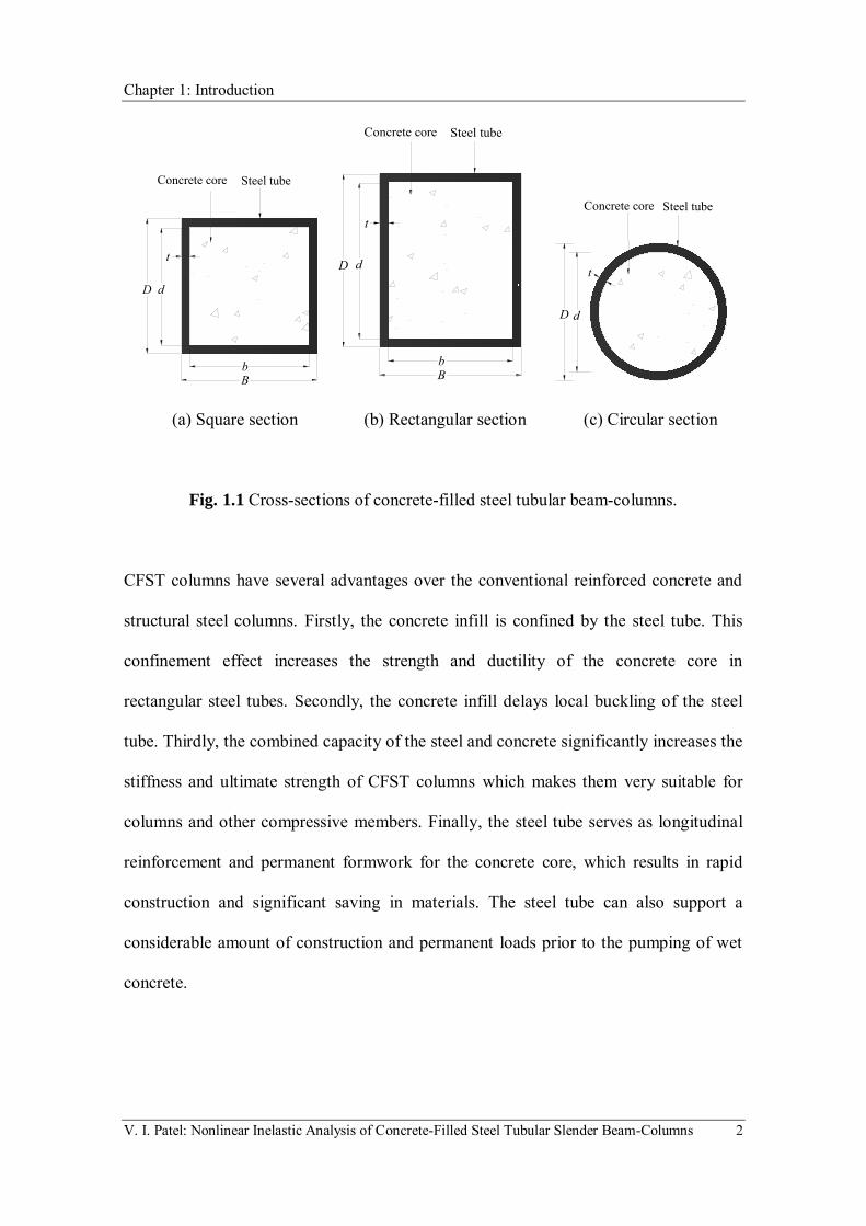
common CFST beam-column sections are shown in Fig. 1.1.
Chapter 1: Introduction
V. I. Patel: Nonlinear Inelastic Analysis of Concrete-Filled Steel Tubular Slender Beam-Columns 2
(a) Square section (b) Rectangular section (c) Circular section
Fig. 1.1 Cross-sections of concrete-filled steel tubular beam-columns.
CFST columns have several advantages over the conventional reinforced concrete and
structural steel columns. Firstly, the concrete infill is confined by the steel tube. This
confinement effect increases the strength and ductility of the concrete core in
rectangular steel tubes. Secondly, the concrete infill delays local buckling of the steel
tube. Thirdly, the combined capacity of the steel and concrete significantly increases the
stiffness and ultimate strength of CFST columns which makes them very suitable for
columns and other compressive members. Finally, the steel tube serves as longitudinal
reinforcement and permanent formwork for the concrete core, which results in rapid
construction and significant saving in materials. The steel tube can also support a
considerable amount of construction and permanent loads prior to the pumping of wet
concrete.
t
Steel tubeConcrete core
bB
dD
dD
Steel tubeConcrete core
t
bB
D d
t
Steel tubeConcrete core

Chapter 1: Introduction
V. I. Patel: Nonlinear Inelastic Analysis of Concrete-Filled Steel Tubular Slender Beam-Columns 3
The in-filled concrete effectively prevents the inward local buckling of the steel tube so
that the steel tube walls can only buckle locally outward. The local buckling modes of
hollow columns and CFST box columns are depicted in Fig. 1.2. The steel tube walls of
a CFST column under axial load and bending may be subjected to compressive stress
gradients. No bifurcation point can be observed on the load-deflection curves of real
steel plates under compressive stresses (Liang and Uy 2000). This is caused by the
presence of initial geometric imperfections in real thin steel plates. This also leads to
difficulty in determining the initial local buckling loads of thin steel plates with
imperfections. The classical elastic local buckling theory cannot be used to determine
the initial local buckling stress of real steel plates with imperfections. The local
buckling of the steel tube walls with initial geometric imperfections and residual
stresses reduces the strength and ductility of thin-walled CFST slender beam-columns.
The local and overall stability problem is encountered in high strength thin-walled
rectangular CFST slender beam-columns with large depth-to-thickness ratios. As a
result, the effects of local buckling must be taken into account in the nonlinear analysis
and design of CFST slender beam-columns.
When a CFST beam-column is used in the corner of a composite building, the beam-
column may be subjected to axial load and biaxial bending. Columns resisting
earthquake or wind loads are also subjected to axial load and bending. In practice, all
CFST columns should be designed to resist the combined actions of axial load and
bending moments. This implies that all columns should be treated as beam-columns.
The design of CFST beam-columns under axial load and bending for strength and
ductility is complex because of the interaction behavior between the axial load and

Chapter 1: Introduction
V. I. Patel: Nonlinear Inelastic Analysis of Concrete-Filled Steel Tubular Slender Beam-Columns 4
bending and the interaction between local and global buckling. In addition, current
design codes do not provide adequate specifications for the design of high-strength
CFST beam-columns under axial load and bending.
(a) Hollow section (b) Concrete-filled section
Fig. 1.2 Local buckling modes of steel box columns.
The common construction practice of a high rise composite building is to erect the
hollow steel columns several storeys ahead before filling the wet concrete. The hollow
steel tubular columns support a considerable amount of construction and permanent
loads. This construction method induces preloads on the steel tubes. These preloads on
the hollow steel columns cause initial stresses and deformations which may
significantly reduce the stiffness and ultimate strength of CFST slender beam-columns.
Therefore, the effects of preloads must be considered in the analysis and design of
CFST slender beam-columns.
Steel box UnfilledSteel box Concrete core
Chapter 1: Introduction
V. I. Patel: Nonlinear Inelastic Analysis of Concrete-Filled Steel Tubular Slender Beam-Columns 5
CFST slender beam-columns may be subjected to a constant axial load and cyclic lateral
loads in seismic regions. The steel tube walls of a cyclically loaded thin-walled
rectangular CFST slender beam-column may undergo cyclic local and overall buckling.
The nonlinear inelastic analysis of thin-walled CFST slender beam-columns is
complicated because it must account for not only material and initial geometric
imperfections as well as second order effects but also the interaction between cyclic
local and overall buckling. Cyclic local buckling of steel tube walls reduces the strength
and ductility of thin-walled CFST slender beam-columns.
The behavior of CFST slender beam-columns depends on many parameters such as the
depth-to-thickness ratio, loading eccentricity ratio, column slenderness ratio, concrete
compressive strengths and steel yield strengths. It is highly expensive and time
consuming to conduct tests to study the effects of every parameter on the behavior of
CFST slender beam-columns. Additionally, the dimensions of the slender column are
usually very large, hence it is impractical to experimentally investigate the effects of
every parameter on the behavior of CFST slender beam-columns under various loading
conditions. In such cases, verified nonlinear inelastic analysis techniques may be the
cost-effective methods for determination of the behavior of full scale CFST slender
beam-columns.
1.2 RESEARCH SIGNIFICANCE
Even though thin-walled high strength CFST slender beam-columns are frequently used
in high rise composite buildings, the understanding of their fundamental behavior is still
Chapter 1: Introduction
V. I. Patel: Nonlinear Inelastic Analysis of Concrete-Filled Steel Tubular Slender Beam-Columns 6
not sufficient and efficient analysis and design methods have not been developed owing
to the lack of experimental and numerical research on this type of composite columns.
The use of high strength concrete in CFST slender columns increases the ultimate
strengths of the composite beam-columns but reduces the ductility of the columns
because of the brittle nature of high strength concrete. On the other hand, the use of the
high strength thin-walled steel tubes leads to economical designs but may cause local
buckling. Local bucking of the steel tubes reduces the ultimate loads of concrete-filled
thin-walled steel box columns. After the onset of initial local buckling, a thin steel plate
can still carry increasing loads without failure. The plate progressively buckles locally
with gradually increasing the load. This behavior of thin steel plates is called post-local
buckling (Liang et al. 2007). The effects of progressive local bucking have not been
considered in existing nonlinear inelastic methods of analysis for CFST slender beam-
columns under static uniaxial loads, biaxial loads, preloads and cyclic loads. The
inelastic analysis methods that do not consider local buckling effects, may overestimate
the ultimate loads of composite columns and frames. The current design codes such as
Eurocode 4 (2004), LRFD (1999) and ACI 318 (2002) do not provide specifications for
the design of high strength CFST slender beam-columns.
The proposed research aims to develop new numerical models for simulating the
nonlinear inelastic behavior of thin-walled high strength CFST slender beam-columns
under various loading conditions. The research findings from this project make
significant contributions to the analysis and design of CFST slender beam-columns
under static uniaxial loads, biaxial loads, preloads and cyclic loads. The numerical
models developed provide structural designers with advanced analysis and design tools

Chapter 1: Introduction
V. I. Patel: Nonlinear Inelastic Analysis of Concrete-Filled Steel Tubular Slender Beam-Columns 7
that can be used to design safe and economical composite buildings. Furthermore, the
proposed numerical models allow the designer to analyse and design CFST beam-
columns made of compact, non-compact or slender steel tubes with any strength grades
and high strength concrete.
1.3 AIMS OF THIS RESEARCH WORK
The main aim of this research work is to develop new efficient numerical models for
predicting the strength and ductility of thin-walled CFST slender beam-columns under
static uniaxial loads, biaxial loads, preloads and cyclic loads. The effects of local
buckling, concrete confinement and high strength materials are taken into account in the
numerical models. Specific aims are given as follows:
Develop a numerical model for high strength rectangular CFST slender beam-
columns under axial load and uniaxial bending with local buckling effects.
Develop a numerical model for biaxially loaded high strength rectangular CFST
slender beam-columns with local buckling effects.
Develop a numerical model for circular high strength CFST slender beam-columns
with preload effects.
Develop a numerical model for high strength thin-walled rectangular CFST slender
beam-columns with preload and local buckling effects.
Develop a numerical model for high strength rectangular CFST slender beam-
columns under cyclic loads.

Chapter 1: Introduction
V. I. Patel: Nonlinear Inelastic Analysis of Concrete-Filled Steel Tubular Slender Beam-Columns 8
Verify numerical models developed by comparisons with existing experimental
results.
Undertake extensive parametric studies to examine the effects of important
parameters on the fundamental behavior of CFST slender beam-columns under
various loading conditions.
1.4 LAYOUT OF THIS THESIS
The contents of this thesis are divided into 7 chapters. Chapter 2 presents an extensive
literature review on the nonlinear analysis and behavior of CFST columns. Published
work on the nonlinear analysis and behavior of CFST beam-columns under axial load
and uniaxial bending is firstly reviewed. Research work on the experimental
investigation and nonlinear analysis of biaxially loaded rectangular CFST beam-
columns is also reviewed. Extensive reviews are then devoted to the preloaded circular
and rectangular CFST beam-columns. Finally, the studies on the CFST beam-columns
subjected to axial load and cyclic loading are highlighted.
A numerical model based on the fiber element analysis method for determining the axial
load-deflection curves and axial load-moment interaction diagrams of rectangular CFST
columns under axial load and uniaxial bending is developed and presented in Chapter 3.
The effects of local buckling, concrete confinement and initial geometric imperfections
are considered in the fiber element analysis program. Computational algorithms based
on the Müller’s method are developed to iterate the neutral axis depth and to adjust the
curvature at the column ends to satisfy equilibrium conditions. Performance indices are

Chapter 1: Introduction
V. I. Patel: Nonlinear Inelastic Analysis of Concrete-Filled Steel Tubular Slender Beam-Columns 9
proposed to quantify the contributions of the concrete core and steel tube to the ultimate
strengths of CFST slender beam-columns. The numerical model developed is employed
to study the effects of key parameters on the ultimate strengths and performance indices
of CFST columns.
Chapter 4 describes a multiscale numerical model for simulating the local and global
buckling behavior of biaxially loaded high strength thin-walled rectangular CFST
slender beam-columns. Mesoscale models based on the fiber element method are
developed for analysing the column cross-section while macroscale models are
proposed to model the axial load-deflection and axial load-moment interaction
responses of slender beam-columns. Müller’s method algorithms are developed and
implemented in the numerical model to iterate the neutral axis depth of the composite
section and the curvature at the column ends until nonlinear solutions are obtained. The
axial load-deflection curves and ultimate strengths of high strength thin-walled
rectangular CFST slender beam-columns obtained from the multiscale numerical model
are compared with the experimental results available in the published literature. Steel
and concrete contribution ratios and strength reduction factor are proposed to quantify
the performance of rectangular CFST beam-columns. The multiscale numerical model
is utilized to investigate the effects of concrete compressive strength, depth-to-thickness
ratio, loading eccentricity ratio and column slenderness ratio on the performance
indices.
In Chapter 5, a numerical model is developed for the nonlinear inelastic analysis of high
strength circular and rectangular CFST slender beam-columns with preload effects. The

Chapter 1: Introduction
V. I. Patel: Nonlinear Inelastic Analysis of Concrete-Filled Steel Tubular Slender Beam-Columns 10
numerical model accounts for the effects of local buckling of steel tubes under stress
gradients, initial geometric imperfections, deflection caused by preloads and concrete
confinement. Müller’s method based on computational algorithms is developed to solve
nonlinear equilibrium equations. The accuracy of the numerical model developed is
verified by comparisons of numerical results with existing experimental data. The
numerical model is utilized to investigate the effects of the preloads, columns
slenderness ratios, diameter-to-thickness ratios, loading eccentricity ratios, steel yield
strengths and concrete confinement on the behavior of normal and high strength circular
and rectangular CFST slender beam-columns under eccentric loading.
Chapter 6 presents a numerical model for simulating the behavior of cyclically loaded
high strength thin-walled rectangular CFST slender beam-columns. The numerical
model considers the effects of cyclic local buckling of the steel tube walls under stress
gradients. The initial geometric imperfections of the slender beam-columns are also
included in the fiber element model. The numerical model is developed using the fiber
element analysis method and is validated against the experimental results. Parametric
studies are performed to investigate the effects of different concrete compressive
strengths, steel yield strengths, depth-to-thickness ratios and column slenderness ratios
on the cyclic load-deflection curves of rectangular CFST beam-columns.
Important conclusions drawn from this research work are given in Chapter 7.
Significant achievements in this research work are summarized. Further research in this
field is also recommended.

Chapter 2: Literature Review
V. I. Patel: Nonlinear Inelastic Analysis of Concrete-Filled Steel Tubular Slender Beam-Columns 11
Chapter 2
LITERATURE REVIEW
2.1 INTRODUCTION
The nonlinear analysis and behavior of CFST beam-columns have been an active
research area for many years. Extensive research and development work has been
undertaken in this area during the last five decades. Several survey papers have
appeared in the literature (Shams and Saadeghvaziri 1997; Shanmugam and Lakshmi
2001; Spacone and El-Tawil 2004). This chapter reviews extensive experimental studies
and the nonlinear analysis of CFST beam-columns.
The nonlinear inelastic analysis of thin-walled CFST beam-columns is a challenging
task as it involves an interaction between local and global buckling of the steel tube.
The fundamental behavior of high strength thin-walled CFST beam-columns is
influenced by many parameters such as the diameter-to-thickness ratios, column

Chapter 2: Literature Review
V. I. Patel: Nonlinear Inelastic Analysis of Concrete-Filled Steel Tubular Slender Beam-Columns 12
slenderness ratios, loading eccentricity ratios, concrete compressive strengths and steel
yield strengths. Experiments can be conducted to investigate the behavior of CFST
beam-columns. However, experimental investigations on CFST beam-columns under
various loading conditions are very expensive and time consuming. In addition, it is not
rational to derive a theory for the design of CFST beam-columns from limited test data.
Experiments should be used to verify a theory for the design of CFST beam-columns
rather than to derive the theory (Liang 2009a). On the other hand, the numerical
modeling can compensate the drawbacks of experiments and can be used to investigate
the behavior of full-scale high strength CFST beam-columns.
There is a wealth of literature in dealing with CFST beam-columns. The literature
review given in the following sections concentrates on experimental works and
nonlinear techniques developed by various researchers to investigate the behavior of
CFST short and slender beam-columns under uniaxial bending, biaxial bending,
preloads and cyclic loading.
2.2 CFST COLUMNS UNDER AXIAL LOAD AND UNIAXIAL
BENDING
CFST columns are often subjected to combined axial load and uniaxial bending in
composite frame structures. CFST columns under axial load and bending are generally
called “beam-columns”. Extensive research has been conducted on the behavior of
CFST beam-columns subjected to axial load and bending. The experimental work on
uniaxially loaded CFST beam-columns is reviewed in the following section. Review on

Chapter 2: Literature Review
V. I. Patel: Nonlinear Inelastic Analysis of Concrete-Filled Steel Tubular Slender Beam-Columns 13
the nonlinear analyses of CFST beam-columns under axial load and uniaxial bending is
given in Section 2.2.2.
2.2.1 Experimental Studies
The first experiment on the ultimate strengths of CFST beam-columns was undertaken
by Klöppel and Goder (1957). Further tests on CFST short beam-columns were
conducted by Furlong (1967) who tested eight circular CFST columns and five square
CFST columns under axial and eccentric loads. The depth-to-thickness ratio of these
tested CFST beam-columns ranged from 29 to 98. He found that the steel and concrete
components independently resisted the axial load applied to the CFST beam-column.
The influences of the steel tube thickness on the ultimate axial strengths of CFST beam-
columns were examined. Experimental results indicated that the thick-walled steel tube
offered confinement to the concrete core in a CFST beam-column. This confinement
effect increased the concrete strength in circular CFST beam-columns. A rectangular
steel tube provided less confinement to the concrete core than a circular steel tube. The
thin-walled steel tubes of CFST beam-columns locally buckled outward due to the
restrains provided by the infilled concrete. It was suggested that a CFST beam-column
cross-section could be treated as a reinforced concrete section for determining the axial
load-moment interaction diagrams.
Tests were carried out by Knowles and Park (1969) to examine the effects of concrete
confinement on the behavior of circular and square CFST beam-columns with various
column slenderness ratios and depth-to-thickness ratios. They studied 12 circular and 7

Chapter 2: Literature Review
V. I. Patel: Nonlinear Inelastic Analysis of Concrete-Filled Steel Tubular Slender Beam-Columns 14
square CFST columns with depth-to-thickness ratios of 15, 22 and 59. Test results
indicated that the confinement of the concrete core provided by the steel tube in a
square CFST column increased only the ductility of the concrete core but not its
ultimate strength. On the other hand, confinement provided by the steel tube increased
both the compressive strength and ductility of the concrete core in a circular CFST
beam-column. However, this confinement effect was shown to decrease with increasing
column slenderness. This has contributed to the fact that the column failed by buckling
before the strain caused an increase in the concrete compressive strength. All CFST
columns tested under axial load failed by column buckling. Local buckling was not
observed in all tested CFST columns. The concrete failure appeared after the maximum
load was reached. The straight line interaction formula for eccentrically loaded CFST
columns was shown to be conservative for short columns and to be unsafe for slender
columns. It was concluded that the tangent modulus method gave good prediction of the
strengths of columns with DL ratios greater than 11 but conservative prediction for
columns with DL ratios less than 11.
The experimental behavior of pin-ended normal strength square CFST slender beam-
columns under axial load and uniaxial bending was investigated by Bridge (1976). A
series of slender column tests was performed to examine the effects of loading
eccentricity, steel tube thickness, column slenderness ratios and uniaxial bending on the
behavior of the slender beam-columns. The test specimens were made of normal
strength steel tubes and concrete. Initial geometric imperfections at the mid-height of
the specimens were measured. Test results indicated that the ultimate axial strengths of
CFST beam-columns increased with increasing the steel tube thickness. Increasing the
Chapter 2: Literature Review
V. I. Patel: Nonlinear Inelastic Analysis of Concrete-Filled Steel Tubular Slender Beam-Columns 15
loading eccentricity ratio decreased the ultimate axial strengths of CFST beam-columns.
In addition, increasing column slenderness ratio reduced the ultimate axial strengths of
CFST beam-columns. The ultimate axial strengths and axial load-deflection curves
measured from the tests were compared with those predicted by an inelastic stability
analysis technique developed by Roderick and Rogers (1969). The local buckling of the
steel tube walls for CFST slender beam-columns was not identified in his tests.
Shakir-Khalil and Zeghiche (1989) tested rectangular CFST slender beam-columns in
single curvature bending. These CFST beam-columns were subjected to axial load and
uniaxial bending. The axial load was applied at an eccentricity about the major or minor
axis. Seven CFST slender beam-columns were tested to failure. One of these columns
was tested under a concentric axial load. The slender beam-columns were constructed
from cold-formed steel tubes and normal strength concrete. The steel yield strengths
varied from 343 MPa to 386 MPa while the concrete compressive strength varied from
40 MPa to 45 MPa. Specimens were fabricated from 5 mm thick steel tubes so that their
depth-to-thickness ratio was 24. Although the initial geometric imperfection was not
measured in the study, the effects of initial geometric imperfection on the ultimate axial
strengths of CFST beam-columns were recognized. Experimental results were compared
with the design loads calculated by BS5400 (1979) and finite element analysis. The
experimental ultimate axial loads, axial load-deflection curves and failure modes of
rectangular CFST beam-columns were reported. It was observed that all tested CFST
columns failed by overall column buckling. The local buckling of the steel tube walls
was not observed in all tested columns. Further tests on normal strength rectangular
CFST slender beam-columns under uniaxial bending were conducted by Shakir-Khalil

Chapter 2: Literature Review
V. I. Patel: Nonlinear Inelastic Analysis of Concrete-Filled Steel Tubular Slender Beam-Columns 16
and Mouli (1990). Three different rectangular CFST column cross-sections were used in
their study such as 120 × 80 × 5 mm, 150 × 100 × 5 mm and 250 × 150 × 6.3 mm. The
yield strength of the steel section varied from 340 MPa to 363 MPa while the concrete
compressive strength ranged from 35 MPa to 40 MPa. The test results showed that the
ultimate axial strength of the CFST slender beam-columns significantly increased when
a larger steel section was used. It was found that the steel tube walls were pushed out by
the crushed concrete which took the shape of the deformed steel section.
The behavior of circular and square CFST columns under axial and uniaxial bending
was investigated experimentally by Matsui et al. (1995). These columns were made of
steel tubes with a yield strength of 445 MPa filled with 32 MPa concrete. The steel tube
had a depth-to-thickness ratio of 33. Test parameters included concrete compressive
strengths, buckling length, depth-to-thickness ratio and loading eccentricity. A total of
sixty columns were tested including twelve hollow steel tubular columns under axial
load. The columns were loaded through hemispherical oil film bearing so that they were
pin-ended in the plane of bending. The design strengths calculated from AIJ
(Architectural Institutive of Japan 1997), modified AIJ and CIDECT (International
committee for the Development and Study of Tubular Structures) design methods were
compared with experimental ultimate axial strengths. It was found that AIJ design
method yielded conservative predictions of the ultimate strengths of slender beam-
columns. Test results indicated that increasing the loading eccentricity reduced the
ultimate axial strengths of the beam-columns. The effects of the loading eccentricity on
the ultimate axial strengths of CFST beam-columns were shown to reduce with an
increase in the column slenderness ratio. The mid-height deflection at the ultimate axial

Chapter 2: Literature Review
V. I. Patel: Nonlinear Inelastic Analysis of Concrete-Filled Steel Tubular Slender Beam-Columns 17
strength of the slender beam-column increased with an increase in the loading
eccentricity. The axial load-moment-interaction diagrams obtained from tests were
compared with those predicted by AIJ and CIDECT for circular and square CFST
beam-columns. The beam-columns with a length-to-depth ratio greater than 18 could
not attain the full plastic moment at the maximum load due to the overall column
buckling.
Shams and Saadeghvaziri (1997) presented a state-of-the art review on CFST columns.
They highlighted the experimental and analytical studies on the design and behavior of
CFST columns. The behavior of circular and rectangular CFST beam-columns under
various loading conditions was discussed in their study. The effects of the cross-section
shape, width-to-thickness ratios and column slenderness ratios on the performance of
CFST beam-columns were summarized. It was found that the confinement of the
concrete core provided by the steel tube increased the strain in the concrete. It was
observed that steel plates buckled outward in one of the sides of a column before the
ultimate axial strength was reached. The remaining sides of a column cross-section were
buckled after the ultimate load was attained. The steel plates were buckled outward in
four sides of a column with large width-to-thickness ratios. In addition, local buckling
of the steel tube occurred after crushing of the concrete core.
The experimental study of axially loaded short CFST columns with depth-to-thickness
ratio ranging from 17 to 50 was undertaken by Schneider (1998). He tested fourteen
specimens to examine the effects of steel tube shape and tube wall thickness on the
ultimate axial strengths of CFST columns. All steel boxes of the specimens were cold-

Chapter 2: Literature Review
V. I. Patel: Nonlinear Inelastic Analysis of Concrete-Filled Steel Tubular Slender Beam-Columns 18
formed carbon steel and were seam welded and annealed to relieve residual stresses.
The yield strength of the steel section varied from 322 MPa to 430 MPa and the
compressive concrete strength ranged from 23 MPa to 30 MPa. Test results indicated
that the post-yield strength and stiffness of circular CFST columns were higher than
those of square or rectangular CFST beam-columns. Local buckling of circular steel
tubes occurred at an axial ductility of 10 or more while square and rectangular tubes
buckled locally at a ductility ranged from 2 to 8. Circular steel tubes possessed higher
post-yield axial ductility and strength than square or rectangular concrete-filled tube
sections. All circular CFST columns displayed the strain hardening which occurred in
rectangular CFST columns with 20tD . The confinement provided by the steel tube
only occurred after the axial load reached about 92% of the column yield strength. The
yield load of a CFST column was found to increase significantly with decreasing the
depth-to-thickness ratio.
Bridge and O’Shea (1998) studied experimentally the behavior of axially loaded thin-
walled steel box sections with or without concrete infill. The width-to-thickness ratios
of these sections ranged from 37 to 131 while the length-to-width ratios of the columns
ranged from 0.8 to 3. The performance of thin-walled CFST short columns was
compared with that of hollow steel tubular columns. The buckling modes for a wide
range of width-to-thickness ratios were examined. It was observed that the concrete core
prevented the inward buckling of the steel tube. This buckling mode significantly
increased the strength of the steel tubes. They suggested that the effective width formula
for clamped steel plates could be used to calculate the strength of thin-walled steel tubes

Chapter 2: Literature Review
V. I. Patel: Nonlinear Inelastic Analysis of Concrete-Filled Steel Tubular Slender Beam-Columns 19
with concrete infill. Local buckling of the steel tubes was found to reduce the ultimate
strength of thin-walled CFST short beam-columns under axial compression.
Experimental studies on the ultimate strengths of high strength thin-walled square CFST
slender beam-columns under axial load and uniaxial bending have been conducted by
Chung et al. (1999). These beam-columns were made of steel tubes with a yield strength
of 445 MPa filled with 88 MPa high strength concrete. The width-to-thickness ratio of
CFST slender beam-columns was 39 while the length of the beam-column ranged from
2250 mm to 3000 mm. The effects of the buckling length-depth ratio and eccentricity of
the applied axial load on the behavior of CFST beam-columns were studied. They found
that local buckling of slender columns under concentric or eccentric loading occurred
after the ultimate axial strength was attained while local buckling of short columns
under concentric load occurred at the ultimate axial strength. The column with a smaller
slenderness ratio had a higher ultimate strength.
O’Shea and Bridge (2000) conducted experiments to study the behavior of circular
CFST short columns. These columns were tested under axial compression which was
applied on either steel tube or both steel tube and concrete core at small eccentricities.
The specimens had a length-to-diameter ratio of 3.5 and diameter-to-thickness ratios
ranging from 60 to 220. The steel tubes were filled with high strength concrete. The
compressive strengths of the concrete cylinders were measured as 50 MPa, 80 MPa and
120 MPa. Test results demonstrated that local buckling remarkably influenced the
strength of hollow steel tubular columns. The bond between the steel tube and concrete
was shown to be critical in determining the mode of local buckling. The sufficient bond

Chapter 2: Literature Review
V. I. Patel: Nonlinear Inelastic Analysis of Concrete-Filled Steel Tubular Slender Beam-Columns 20
between the steel tube and concrete core prevents the buckling of the steel tube. In
addition, the confinement of the concrete core provided by the circular steel tube was
affected by the loading conditions. The effect of the confinement increased with
increasing the axial load applied on the concrete core. Design methods were suggested
for determining the strength of circular CFST columns subjected to various loading
conditions. The strengths obtained from these design methods were compared with
experimental strengths. The comparison was also conducted between the design method
and Eurocode 4. They reported that Eurocode 4 provided conservative strength
predictions for circular steel tubes filled with concrete strength up to 50 MPa and
subjected to axial load and bending.
Han (2002) investigated experimentally the influences of constraining factors and the
depth-to-width ratios on the ultimate strength and ductility of axially loaded rectangular
CFST columns. A total of 24 CFST columns were tested. The main variables examined
in the test program were the constraining factor and depth-to-width ratio. The width of
the steel tubes varied from 70 mm to 160 mm while the depth of the steel tubes ranged
from 90 mm to 160 mm. The short columns were constructed by steel tubes filled with
high strength concrete of 60 MPa. The steel yield strength varied from 194 MPa to 228
MPa. He reported that the axial strength and ductility of CFST columns decreased with
an increase in the depth-to-width ratio but increased with an increase in the constraining
factor. A confinement factor was proposed for determining the section performance of
composite columns but it did not take into account the effects of tb ratios on the
behavior of composite sections.

Chapter 2: Literature Review
V. I. Patel: Nonlinear Inelastic Analysis of Concrete-Filled Steel Tubular Slender Beam-Columns 21
Zhang et al. (2003) presented test results of 8 high strength CFST beam-columns
subjected to axial load and uniaxial bending. A 150 × 150 mm cross-section was used in
the tests. Test parameters included column slenderness ratios, steel ratios and loading
eccentricity. Test specimens were made of high strength concrete with the compressive
strength of 94 MPa and steel tubes with yield strengths of 316 MPa or 319 MPa. Their
test results indicated that increasing the column slenderness ratio and loading
eccentricity reduced the ultimate axial strengths of CFST beam-columns. The ultimate
axial strengths of CFST beam-columns were shown to decrease with increasing the steel
ratio.
Han and Yang (2003) carried out several tests to study the behavior of rectangular
CFST short columns under long-term sustained loading. They investigated the effects of
steel ratios, long-term sustained load level, slenderness ratio, strength of the materials
and depth-to-thickness ratio on the ultimate strengths of CFST columns. A theoretical
model given in ACI codes (ACI 1992) was used to compare the predicted behavior of
CFST columns under long-term loading. It was found that the axial strain due to long-
term sustained loading affected the results and tended to stabilize after about 100 days
of loading. The strength index decreased as the slenderness ratio and the concrete
strength increased, when the slenderness ratio was less than 10. The maximum strength
reduction due to long-term loading effects was approximately 20% of the strength under
short-term loading. A set of formulas was developed by Han and Yang (2003) for
predicting the ultimate strengths of rectangular CFST short columns with long-term
sustained loading effects.
Chapter 2: Literature Review
V. I. Patel: Nonlinear Inelastic Analysis of Concrete-Filled Steel Tubular Slender Beam-Columns 22
Fujimoto et al. (2004) examined experimentally the effects of high strength materials on
the behavior of circular and square CFST short columns under eccentric loading. They
tested CFST short columns with a wide range of parameters including the tubes’
diameter-to-thickness ratio, normal and high strength concrete, and normal and high
strength steels. Circular steel tubes used to construct these CFST columns were cold
formed from a flat plate by press welding and seam welding. The length-to-diameter
ratio of the specimens was 3.0. The depth-to-thickness ratios of these specimens ranged
from 27 to 101. The yield strengths of the steel tubes were 283, 579 and 834 MPa and
the concrete cylinder compressive strengths were 25, 41 and 78 MPa. The applied axial
load ranged from 13% to 59% of the ultimate axial load of corresponding column
obtained by the theoretical model. They reported that the use of high strength concrete
reduced the ductility of circular CFST beam-columns. Also, the use of high strength
steel tubes or steel tubes with a smaller diameter-to-thickness ratio increased the
ductility of circular CFST columns. It was concluded that the confinement effect did not
increase the moment capacity of square CFST beam-columns and local buckling must
be taken into account in evaluating the strengths of square CFST beam-columns with
large width-to-thickness ratios.
Sakino et al. (2004) have investigated experimentally the ultimate loads and behavior of
circular CFST short columns under axial load. They tested 114 CFST columns to study
the effects of the tube shape, steel yield strengths, diameter-to-thickness ratio and
concrete strengths on the behavior of axially loaded CFST columns. The circular steel
tubes used in these CFST columns were cold formed from a flat plate by press bending
and seam welding. The depth-to-thickness ratios of these columns ranged from 17 to

Chapter 2: Literature Review
V. I. Patel: Nonlinear Inelastic Analysis of Concrete-Filled Steel Tubular Slender Beam-Columns 23
102. The yield strengths of steel tubes ranged from 279 MPa to 853 MPa. The concrete
cylinder compressive strengths ranged from 25 MPa to 85 MPa. The test data was used
to develop design methods for CFST columns. A new design formula based on the test
results was also proposed for circular and square CFST columns.
The behavior of axially loaded circular CFST short columns with various concrete
strengths was presented by Giakoumelis and Lam (2004). The effects of the steel tube
thickness, the bond strength between the concrete and the steel tube and concrete
confinement on the behavior of circular CFST short columns were examined. They
tested 15 circular CFST short columns with concrete compressive strengths of 30, 60
and 100 MPa and depth-to-thickness ratios varied from 23 to 31. The yield strength of
the steel tube was either 343 MPa or 365 MPa. The diameter of the circular CFST short
columns was 114 mm. The length of the beam-columns was 300 mm. They compared
various design codes for circular CFST columns. They reported that Eurocode 4
provided accurate strength predictions for circular CFST beam-columns with normal
and high strength concrete. Their results indicated that the concrete strength had a
considerable effect on the bond between the steel tube and concrete core.
Liu (2006) undertook experimental studies on the structural behavior of high strength
rectangular CFST beam-columns subjected to axial load and uniaxial bending. He tested
four slender and sixteen stub rectangular high strength steel tubes with yield strength of
495 MPa filled with high strength concrete of 60 MPa. The ultimate axial strengths of
CFST columns measured from the tests were compared with the design ultimate loads
calculated using Eurocode 4. It was shown that EC4 accurately predicted the ultimate

Chapter 2: Literature Review
V. I. Patel: Nonlinear Inelastic Analysis of Concrete-Filled Steel Tubular Slender Beam-Columns 24
axial strengths of axially loaded CFST columns, but was quite conservative for
predicting the ultimate axial strengths of eccentrically loaded CFST columns. The
conservatism of the EC4 predictions increased as the eccentricity increased. Moreover,
the ultimate capacities of CFST slender beam-columns were significantly reduced by
increasing the load eccentricity ratio.
Lue et al. (2007) tested twenty-four rectangular CFST slender beam-columns with a
depth-to-thickness ratio of 33 and concrete compressive strengths varying from 29 to 84
MPa. These beam-columns with a cross-section of 100 × 150 mm were constructed by
cold-formed steel tubes. Specimens were fabricated from 4.5 mm thick steel tube so that
their depth-to-thickness ratio was 33. The length of the column was 1855 mm. The yield
strength of the steel tube was 379 MPa. It was observed that CFST columns with
normal strength concrete failed by the global buckling while local buckling failure mode
was found in the specimens with high strength concrete. Test results were compared
with various composite design codes to examine the validity of the design codes. It was
concluded that the AISC-LRFD (2005) generally gave a good estimate of the ultimate
loads of high strength CFST columns while the AISC-LRFD (1999) overestimated the
ultimate loads of high strength CFST columns.
Experiments on high strength circular CFST slender beam-columns under axial load and
bending were undertaken by Lee et al. (2011). They studied the effects of the diameter-
to-thickness ratios and loading eccentricity ratios on the axial load-deflection responses
and axial load-moment interaction diagrams of CFST beam-columns. Their studies
indicated that the confinement effect on the ultimate bending strength was insignificant

Chapter 2: Literature Review
V. I. Patel: Nonlinear Inelastic Analysis of Concrete-Filled Steel Tubular Slender Beam-Columns 25
for the beam-column with diameter-to-thickness ratios ranging from 40 to 100 and
loading eccentricity ratios ranging from 0.2 to 0.5. In addition, the axial stiffness and
flexural rigidity of a circular CFST column decreased with an increase in the diameter-
to-thickness ratio. The ductility of normal strength circular CFST beam-columns was
higher than that of high strength circular CFST beam-columns.
Portolés et al. (2011) described results obtained from a series of 37 tests on normal and
high strength circular CFST slender beam-columns under eccentric loading. The
specimens were tested under eccentric compression to investigate the effects of the
concrete compressive strengths, diameter-to-thickness ratio, loading eccentricity ratio
and column slenderness ratio. The ultimate axial strengths obtained from the
experiments were compared with the design ultimate loads calculated using the design
rules specified in Eurocode 4. They used performance indices to quantify the effects of
the primary variables on the ultimate axial strength and ductility of circular CFST
slender beam-columns. Design recommendations based on the test results were
proposed for high strength circular CFST beam-columns. It was concluded that the
ultimate axial strength of eccentrically loaded circular CFST beam-columns decreased
with increasing either the column slenderness ratio or loading eccentricity ratio but
increased due to the use of either high strength concrete or small depth-to-thickness
ratio of the steel tube.
Uy et al. (2011) carried out an experimental investigation on concrete-filled stainless
steel tubular short and slender columns with circular, square and rectangular cross-
sections. The ultimate axial strengths, failure modes, axial load-strain relationships,

Chapter 2: Literature Review
V. I. Patel: Nonlinear Inelastic Analysis of Concrete-Filled Steel Tubular Slender Beam-Columns 26
axial load-shorting curves and axial load-deflection responses were measured in the
tests. The experimental ultimate axial strengths of CFST columns were compared with
the design strengths calculated using AS 5100 (2004), AISC (2005), Chinese code
DBJ/T (2010) and Eurocode 4 (2004) for CFST columns. The authors concluded that
AS 5100, AISC, DBJ/T and EC4 underestimated the ultimate axial strengths of
concrete-filled stainless steel tubular columns under axial compression.
Ellobody and Ghazy (2012a, 2012b) studied the experimental behavior of pin-ended
fiber reinforced concrete-filled stainless steel tubular columns under axial and eccentric
loads. The length of composite columns varied from short to slender. The circular
stainless steel tubes used in the tests were cold-rolled from flat strips of austenitic
stainless steel. The tubes had an outer diameter of 100 mm and a plate thickness of 2
mm so that the tubes had diameter-to-thickness ratio of 50. The stainless steel tubes
were filled with plain and polypropylene fiber reinforced concrete having a nominal cub
strength of 40 MPa. The ultimate axial strengths, axial load-strain curves, axial load-
shortening relationships and axial load-deflection responses of circular concrete-filled
stainless steel tubular columns were measured. Four failure modes such as the stainless
steel yielding, local buckling, concrete crushing and flexural buckling were observed.
Test results indicated that fiber reinforced CFST columns had improved ductility
compared with plain CFST columns. It was concluded that the EC4 accurately predicted
the ultimate loads of axially loaded concrete-filled stainless steel circular tubular
columns, but was quite conservative for predicting the ultimate loads of the
eccentrically loaded columns. The conservatism of the EC4 predictions increased as the
eccentricity increased.
Chapter 2: Literature Review
V. I. Patel: Nonlinear Inelastic Analysis of Concrete-Filled Steel Tubular Slender Beam-Columns 27
A test was undertaken by Liew and Xiong (2012) to investigate the behavior of 27
axially loaded CFST columns. Steel fibers were added into the ultra-high strength
concrete. The effects of ultra-high strength concrete on the strength and ductility of
CFST column were studied. Test results demonstrated that the ultra-high strength
concrete increased the ultimate strengths of CFST columns but reduced the ductility of
the columns because of the brittle nature of the ultra-high strength concrete. However,
the ductility and strength of CFST columns with ultra-high strength concrete increased
with an increase in the steel contribution ratio. The use of fiber reinforced concrete in
CFST beam-columns resulted in the similar behavior. The experimental ultimate axial
strengths were compared with the design strengths calculated by Eurocode 4. It was
shown that the EC4 accurately predicted the ultimate strengths of axially loaded ultra-
high strength concrete columns.
Abed et al. (2013) carried out tests on 16 CFST short columns under axial load. The
steel tubes were filled with normal and high strength concrete having a compressive
strength of 44 MPa or 60 MPa. The diameter-to-thickness ratios of 20, 32 and 54 were
considered in the experimental investigation. The main variable parameters in the tests
were the concrete compressive strength and diameter-to-thickness ratio. Test results
indicated that the ultimate axial strength of circular CFST columns increased with an
increase in the concrete compressive strength. The ductility of circular CFST columns
decreased with an increase in the concrete compressive strength for larger diameter-to-
thickness ratios. Increasing in the diameter-to-thickness ratio reduced the stiffness and
ultimate axial strength of axially loaded circular CFST short columns. The ultimate
axial strengths measured from the tests were compared with the design strengths

Chapter 2: Literature Review
V. I. Patel: Nonlinear Inelastic Analysis of Concrete-Filled Steel Tubular Slender Beam-Columns 28
calculated by the theoretical equation, AISC code (2010), American Concrete Institute
(ACI 2011) and Australian Standard (AS 2009) codes, Giakoumelis and Lam (2004)
equations, Mander et al. (1988) equations and Eurocode 4 (2005). They concluded that
the equations given by Mander et al. (1988) gave a good estimate of the ultimate loads
of CFST columns while AISC, ACI and AS and Eurocode 4 underestimated the
ultimate loads of CFST columns up to 43%. These design codes except Eurocode 4 for
CFST beam-columns have not considered the effects of concrete confinement that
significantly increase the strength and ductility of the concrete core. As a result, the
ultimate loads calculated by these codes deviate considerably from experimental results.
It can be seen from the past experimental investigations that the behavior of uniaxially
loaded high strength thin-walled rectangular CFST slender beam-columns has not been
adequately investigated. Literature review on nonlinear analysis techniques for
predicting the behavior of CFST columns under axial load and uniaxial bending is
provided in the following section.
2.2.2 Nonlinear Analysis
Neogi et al. (1969) proposed a numerical model for predicting the elasto-plastic
behavior of pin-ended circular CFST slender beam-columns under eccentric loading. In
the numerical model, the tangent modulus method was used to analyze axially loaded
columns while eccentrically loaded beam-columns were analyzed by assuming a
displacement function. However, the effects of the concrete tensile strength and
concrete confinement were not taken into account in their numerical model. As a result

Chapter 2: Literature Review
V. I. Patel: Nonlinear Inelastic Analysis of Concrete-Filled Steel Tubular Slender Beam-Columns 29
of this, their numerical model was found to underestimate the ultimate strengths of
circular CFST slender beam-columns. The load-deflection analysis procedure presented
by Neogi et al. (1969) can be used to develop strength envelopes by varying the loading
eccentricity. However, it is not efficient when the loading eccentricity is large. Despite
of this, the axial load-moment interaction diagrams of circular CFST slender beam-
columns have not been studied by Neogi et al. (1969).
Tang et al. (1996) proposed a confining pressure model for concrete in circular CFST
columns. The model accounts for the effects of material and geometric properties of the
column on the strength enhancement and the post-peak behavior. It was found that their
model generally overestimated the lateral confining pressure in circular CFST columns
(Liang and Fragomeni 2009). Susantha et al. (2001) proposed uniaxial stress-strain
relationships for concrete confined by various shaped steel tubes. Susantha et al. (2001)
used the confining pressure model proposed by Tang et al. (1996) for circular CFST
columns.
The nonlinear behavior of CFST short columns was discussed by Schneider (1998) who
developed a nonlinear three-dimensional finite element model for the analysis of CFST
columns. The model was developed using the finite element program ABAQUS. An
eight-node shell element was employed to model the steel tube while the concrete core
was modeled using 20-node brick elements. The model considered the inelastic
behavior of structural steels and concrete. The Prandtl-Reuss flow rule was used to
determine the inelastic deformation of steel plates while von Mises yield criteria were
employed to define the yield surfaces. The results obtained from the finite element

Chapter 2: Literature Review
V. I. Patel: Nonlinear Inelastic Analysis of Concrete-Filled Steel Tubular Slender Beam-Columns 30
analysis were compared with experimental results. It was shown that the elastic and
plastic behavior of CFST beam-column specimens could be predicted by the finite
element model. However, the ultimate axial strengths predicted by the finite element
model were slightly higher than the test results.
Vrcelj and Uy (2002) presented a numerical model for simulating the load-deflection
responses of high strength square CFST slender beam-columns under axial load and
uniaxial bending. They investigated the effects of compressive strengths, steel yield
strengths and column slenderness ratios on the ultimate axial strengths of high strength
square CFST slender beam-columns. However, their model did not account for the
effects of confinement provided by the steel box on the ductility of the concrete core
and progressive local buckling of thin steel plates under stress gradients. The axial load-
moment interaction diagrams of high strength rectangular CFST slender beam-columns
have not been studied by Vrcelj and Uy (2002).
Hu et al. (2003) developed a finite element model for the nonlinear analysis of axially
loaded CFST short beam-columns with confinement effect. They employed the general
purpose finite element analysis program ABAQUS to study the inelastic behavior of
CFST beam-columns. Square and circular concrete-filled sections with stiffened
reinforcing ties were used in the nonlinear analysis. The steel tubes were simulated
using an elastic-perfectly-plastic model with associated flow theory while an elastic-
plastic theory with associated flow and isotropic hardening rule was used to model the
concrete. The von Mises yield criterion was employed to define the elastic limit of the
steel tubes when it was subjected to multiple stresses. On the other hand, a linear

Chapter 2: Literature Review
V. I. Patel: Nonlinear Inelastic Analysis of Concrete-Filled Steel Tubular Slender Beam-Columns 31
Drucker-Prager yield criterion was used to model the yield surfaces of the concrete
because the concrete is usually subjected to triaxial compressive stress and failure of the
concrete is dominated by increasing in the hydrostatic pressure. The interaction between
the concrete core and steel tube was modeled by special nine-node interface elements.
The finite element model was verified by experimental results. They concluded that
circular steel tube provided a good confining effect on concrete core especially when
the width-to-thickness ratio of the steel tube was small and local buckling of the steel
tube was not occurred. However, square CFST beam-columns did not provide a good
confining effect on the concrete core especially when the width-to-thickness ratio of the
steel tube was larger and the steel tube was buckled locally outward. They proposed a
confining pressure model for concrete in circular CFST beam-columns made of normal
strength steel and concrete. However, their confining pressure model was found to
overestimate the confining pressure in high strength circular CFST columns with depth-
to-thickness ratio less than 47 (Liang and Fragomeni 2009).
Liang and Uy (2000) investigated the post-local buckling behavior and ultimate strength
of thin steel plates in rectangular CFST columns using the nonlinear finite element
analysis method. In their investigation, an eight-node quadratic plate element based on
the Mindlin plate theory was used to describe the local buckling displacement of the
plate in the finite element analysis. The plate was divided into 10 layers in order to treat
the plasticity of the plate by using the von Mises yield criterion with volume approach.
The effects of geometric imperfection, slenderness ratio and residual stress on the post-
local buckling strengths of clamped steel plates were studied. Well-known Ramberg-
Osgood formula was employed to model steel plates with residual stresses. They found

Chapter 2: Literature Review
V. I. Patel: Nonlinear Inelastic Analysis of Concrete-Filled Steel Tubular Slender Beam-Columns 32
that the residual stresses had considerable effects on the load-deflection behavior of
clamped plates, and the stiffness and ultimate strength of plates decreased by increasing
the residual stresses. It is worth mentioning that the method developed by Liang and Uy
(2000) is an efficient theoretical method for determining the initial local buckling loads
and the post-local buckling reserve strengths of plates with imperfections.
Ellobody et al. (2006) presented the design and behavior of circular CFST short
columns under axial compression. They employed the finite element program ABAQUS
to study the inelastic behavior of normal and high strength circular CFST short columns
under axial compression. The compressive strength of concrete ranged from 30 MPa to
110 MPa covering normal and high strength concrete. The finite element analysis was
conducted on columns with a wide range of diameter-to-thickness ratios ranging from
15 to 80 which covers non-compact and compact steel tube sections. The concrete
confinement model proposed by Hu et al. (2003) was used in the finite element analysis.
The ultimate axial strengths and axial load-shortening curves for circular CFST columns
were evaluated. The finite element results were compared with the test results provided
by Giakoumelis and Lam (2004) and Sakino et al. (2004). Parametric studies were
conducted to examine the effects of concrete compressive strengths, steel yield strengths
and diameter-to-thickness ratios. The ultimate axial strengths obtained from the finite
element analyses were compared with the design strengths calculated using Australian,
American and European specifications. They reported that the design strengths obtained
by Australian and American specifications were conservative.

Chapter 2: Literature Review
V. I. Patel: Nonlinear Inelastic Analysis of Concrete-Filled Steel Tubular Slender Beam-Columns 33
Liang et al. (2007) investigated the local and post-local buckling behavior of thin steel
plates in CFST beam–columns using the nonlinear finite element method. Clamped
steel plates with various width-to-thickness ratios and restrained by the concrete core
were studied. Geometric and material nonlinear effects were considered in their study.
A 10 ×10 mesh was used in the analyses in order to obtain accurate results. The material
plasticity was defined by the von Mises yield criterion. They found that increasing the
width-to-thickness ratio of a steel plate under the predefined stress gradients reduced its
lateral stiffness, initial local buckling stress and ultimate strength. They proposed
formulas for predicting the initial local buckling stresses of thin steel plates in CFST
beam-columns with initial geometric imperfections and residual stresses. They also
proposed effective strength and width formulas for determining the post local buckling
strengths of steel plates in thin-walled CFST beam-columns. It is worth mentioning that
the formulas proposed by Liang et al. (2007) can be used directly in the design of thin-
walled CFST beam-columns. In addition, they can be incorporated in numerical models
to account for local buckling effects on the behavior of CFST beam-columns under
various loading conditions.
Numerical models for the nonlinear inelastic analysis of circular CFST short columns
under axial and eccentric loading were developed by Liang and Fragomeni (2009,
2010). They proposed constitutive material models for confined concrete. The
numerical models incorporated accurate constitutive models for normal and high
strength concrete confined by either normal or high strength circular steel tubes. In their
study, a circular CFST section was divided into fine fiber elements which were assigned
with either steel or concrete material properties. The coordinates and cross-section area

Chapter 2: Literature Review
V. I. Patel: Nonlinear Inelastic Analysis of Concrete-Filled Steel Tubular Slender Beam-Columns 34
of each element were automatically calculated based on the geometry of the cross-
section. Fiber stresses were calculated from fiber strains. Secant method algorithms
developed by Liang (2009b) were incorporated in the numerical models to iterate the
neutral axis depth in a circular CFST beam-column section until the force equilibrium
conditions were satisfied. The accuracy of the numerical models was examined by
comparing the ultimate axial strengths, ultimate bending strengths, axial load-strain
curves and moment-curvature responses with corresponding experimental results. The
accuracy and reliability of various confining pressure models proposed by Tang et al.
(1996), Hu et al. (2003) and the authors were evaluated. It was found that the confining
pressure models given by Tang et al. (1996) and Hu et al. (2003) overestimated the
ultimate axial strengths of high strength circular CFST columns. The comparison
demonstrated that the confining pressure models proposed by Liang and Fragomeni
(2009) provided reliable results for both normal and high strength circular CFST
columns under axial and eccentric loading. The verified numerical models were then
utilized to investigate the fundamental behavior of circular CFST columns with various
diameter-to-thickness ratios, concrete compressive strengths, steel yield strengths, axial
load levels and section shapes. They proposed new design models based on the
numerical results for determining the ultimate axial and ultimate pure bending strengths
of circular CFST beam-columns. They highlighted that the numerical models and
formulas were shown to be effective simulation and design tools for circular CFST
beam-columns under axial and eccentric loading.
An analytical model for determining the behavior of axially loaded circular CFST short
columns was described by Choi and Xiao (2010). An analytical procedure for predicting

Chapter 2: Literature Review
V. I. Patel: Nonlinear Inelastic Analysis of Concrete-Filled Steel Tubular Slender Beam-Columns 35
the axial load-strain curves of circular CFST short beam-columns was presented.
Various modes of the interaction between the steel tube and infill concrete under axial
compression were discussed. The axial load-strain curves for circular CFST short
columns under axial compression predicted by the analytical model were compared with
experimental data. They found that the behavior of circular CFST short columns
depended on the concrete strength and confinement of the concrete provided by the steel
tube. The drawbacks of the analytical procedure are that the strain hardening of
materials was not taken into account. Consequently, the procedure produced solutions
that deviated considerably from the corresponding experimental results in the post-peak
range of the axial load-strain curves.
The nonlinear inelastic behavior of high strength circular CFST slender beam-columns
was investigated by Liang (2011a, 2011b). He developed a numerical model based on
the accurate fiber element method. Material constitutive material model proposed by
Liang and Fragomeni (2009) for confined concrete was incorporated in the numerical
model. The numerical model accounted for the effects of concrete confinement, initial
geometric imperfection and second order. The cross-section analysis of circular CFST
beam-columns was discussed. In his numerical model, the deflected shape of circular
CFST beam-columns was assumed to be a part of sine curve. Computational algorithms
based on the secant method were developed to adjust the neutral axis depth of the
composite section. In the axial load-deflection analysis, the deflection at the mid-height
of a slender beam-column was gradually increased. The equilibrium of internal and
external bending moments was maintained at the mid-height of the beam-column. In
axial load-moment interaction strength analysis, the curvature at the mid-height of the

Chapter 2: Literature Review
V. I. Patel: Nonlinear Inelastic Analysis of Concrete-Filled Steel Tubular Slender Beam-Columns 36
beam-column was gradually increased. The curvature at the column end was iteratively
adjusted by the secant method to satisfy the moment equilibrium at the mid-height of
the beam-column. The ultimate axial strengths, ultimate bending strengths and axial
load-deflection responses of circular CFST slender beam-columns under eccentric
loading obtained from numerical model were compared with experimental results
available in the published literature. The numerical model was then utilized to
investigate the effects of column slenderness ratio, loading eccentricity ratio, concrete
compressive strengths, steel yield strengths, steel ratio and concrete confinement on the
behavior of high strength circular CFST slender beam-columns in terms of axial load-
deflection responses, ultimate strengths, axial load-moment interaction diagrams and
strength increase due to confinement effects. It was concluded that increasing column
slenderness ratio and eccentricity ratio significantly reduced the flexural stiffness and
ultimate axial strength of eccentrically loaded circular CFST beam-columns. The
deflections and displacement ductility of the beam-columns increased with an increase
in the column slenderness ratio. In addition, the stiffness and strength of circular CFST
slender beam-columns increased with increasing the concrete compressive strength. It
was noted that the steel yield strength did not have an effect on the initial flexural
stiffness of slender beam-columns. However, the ultimate axial strengths of slender
beam-columns increased significantly with increasing the steel yield strength.
Moreover, the flexural stiffness and ultimate strength were shown to increase
significantly with increasing the steel ratio. The confinement effect was shown to
decrease with increasing the eccentricity ratio and the column slenderness ratio.

Chapter 2: Literature Review
V. I. Patel: Nonlinear Inelastic Analysis of Concrete-Filled Steel Tubular Slender Beam-Columns 37
Portolés et al. (2011) proposed numerical procedures for predicting the axial load-
deflection responses of high strength circular CFST slender beam-columns under
eccentric loading. The effects of initial geometric imperfection on the performance of
circular CFST slender beam-columns were incorporated in the numerical model. The
confinement provided by the circular steel tube was also considered. The ultimate axial
strengths and axial load-deflection curves obtained from the numerical model were
compared with experimental data to examine the accuracy of the numerical model. It
was found that the numerical model predicted well the behavior of normal and high
strength circular CFST slender beam-columns. A parametric study was conducted to
investigate the effects of confinement index, column slenderness ratio and concrete
compressive strengths on the ultimate axial strengths, concrete contribution ratio and
strength index of CFST beam-columns. Recommendations for the design of CFST
slender beam-columns were given based on the parametric study.
El-Heweity (2012) employed the finite element program ANSYS to study the inelastic
behavior of axially loaded high strength circular CFST short columns. The finite
element model incorporated the constitutive models for steels and concrete. The finite
element model was verified by comparisons with experimental results. The fundamental
behavior of circular CFST beam-columns with various column diameters and steel yield
strengths was studied. Strength enhancement factor and ductility index were proposed
to quantify the performance of the CFST beam-columns. They reported that the steel
yield strength did not have a significant influence on the concrete ductility in circular
CFST columns. However, the steel yield strength had considerable effect on the
concrete strength of circular CFST beam-columns.

Chapter 2: Literature Review
V. I. Patel: Nonlinear Inelastic Analysis of Concrete-Filled Steel Tubular Slender Beam-Columns 38
Ellobody (2013) discussed the nonlinear behavior of fiber reinforced concrete-filled
stainless steel tubular (CFSST) columns. A three-dimensional finite element model was
developed using ABAQUS for the analysis of CFSST columns. The pin-ended axially
loaded CFSST columns were considered in the finite element model. The length of
CFSST columns varied from short to slender. The effects of fiber reinforced concrete
confinement provided by stainless steel tube and interface between the stainless steel
tube and fiber reinforced concrete were also considered in the analysis. In addition, the
initial geometric imperfection was incorporated in the finite element model. The finite
element model had been validated against tests conducted by Ellobody and Ghazy
(2012a) and Ellobody and Ghazy (2012b) on fiber reinforced concrete-filled stainless
steel tubular columns. The ultimate axial strengths, axial load-strain curves and failure
modes obtained from the finite element model were compared with experimental
results. The finite element model was shown to be accurate for predicting the nonlinear
behavior of fiber reinforced concrete-filled stainless steel tubular columns. A parametric
study was conducted to investigate the influence of the depth-to-thickness ratios, fiber
reinforced concrete compressive strengths and column slenderness ratio on the behavior
of fiber reinforced concrete-filled stainless steel tubular columns. The parametric study
indicated that increasing the concrete compressive strength significantly increased the
ultimate axial strength for the columns with DL ratio less than 6 and depth-to-
thickness ratio less than 50. The ultimate axial strengths obtained from the finite
element model were compared with the design strengths calculated using Eurocode 4
for composite columns. It was shown that the EC4 predicted well the design strengths of
axially loaded fiber reinforced CFST columns.

Chapter 2: Literature Review
V. I. Patel: Nonlinear Inelastic Analysis of Concrete-Filled Steel Tubular Slender Beam-Columns 39
It is evident from the above literature review that there is a lack of numerical studies on
high strength thin-walled rectangular CFST slender beam-columns. It is also shown that
existing numerical models do not consider the effects of progressive local and post-local
buckling of steel tube walls under stress gradients on the behavior of CFST slender
beam-columns. In addition, the effects of high strength materials on the behavior of
rectangular CFST slender beam-columns under uniaxial bending have not been studied
adequately. Furthermore, the axial load-moment interaction diagrams of uniaxially
loaded high strength thin-walled rectangular CFST slender beam-columns have not
been investigated.
2.3 CFST COLUMNS UNDER AXIAL LOAD AND BIAXIAL
BENDING
In practice, CFST columns in composite buildings are often subjected to axial load and
biaxial bending. Experimental and numerical studies have been carried out on the
behavior of CFST beam-columns under axial load and biaxial bending. Reviews on
experimental investigations and nonlinear analysis of biaxially loaded CFST beam-
columns are given in this section.
2.3.1 Experimental Studies
Bridge (1976) presented an experimental study on the behavior of biaxially loaded
square CFST slender beam-columns with a depth-to-thickness ratio of 20. The angle of

Chapter 2: Literature Review
V. I. Patel: Nonlinear Inelastic Analysis of Concrete-Filled Steel Tubular Slender Beam-Columns 40
applied load was fixed at 0˚, 45˚ or 60˚. The square CFST column section of 200 × 200
mm was considered in his study. Test parameters included the loading eccentricity,
column slenderness ratio and biaxial bending. Experimental results demonstrated that
the ultimate axial strength of slender square columns was shown to decrease with
increasing the loading eccentricity. Increasing the column slenderness ratio significantly
reduced the ultimate axial strengths of eccentrically loaded square CFST slender beam-
columns. It was observed that all tested columns with compact sections failed by overall
buckling with no sign of local buckling.
Shakir-Khalil and Zeghiche (1989) conducted tests on 7 full-scale rectangular CFST
slender beam-columns. One column was tested under axial load, four columns were
subjected to axial load and uniaxial bending and two columns were tested under axial
load and biaxial bending. The bond between the steel tube and concrete core were
studied. The effects of loading eccentricity on the behavior of slender beam-columns
were examined. They found that the primary moment caused by the loading eccentricity
had a pronounce effect on the ultimate axial strengths of CFST slender beam-columns
with a small eccentricity. On the other hand, the secondary moment induced from the
second order effect had a significant effect on the behavior of CFST slender beam-
column with a large loading eccentricity ratio. The effect of initial geometric
imperfection was recognized, although it was not measured for the tested columns. A
linear distribution of strains through the cross-section was observed for all tested
columns. All tested columns were failed by overall flexural buckling. Local buckling
was not observed in the tested columns. The experimental results were compared with
the results obtained from a finite element analysis and BS5400 (1979). The prediction

Chapter 2: Literature Review
V. I. Patel: Nonlinear Inelastic Analysis of Concrete-Filled Steel Tubular Slender Beam-Columns 41
of BS5400 (1979) for eccentrically loaded CFST columns was shown to unsafe for
columns subjected to minor axis bending.
Shakir-Khalil and Mouli (1990) carried out further study on rectangular CFST slender
beam-columns. The steel section of 150 × 100 × 5 mm was used in the tests. Tests on
nine rectangular CFST slender beam-columns were conducted. Some of the columns
were subjected to axial load and uniaxial bending, but most of the columns were tested
under axial load and biaxial bending. Test parameters included the column cross-section
size, steel yield strengths, concrete compressive strengths and column length. Test
results demonstrated that the ultimate axial strength of rectangular CFST slender beam-
columns increased with an increase in the size of the steel section. Increasing the
concrete compressive strength increased the ultimate axial strength of CFST beam-
columns. In addition, increasing the column length reduced the ultimate axial strength
of CFST beam-columns.
Mursi and Uy (2006a) studied the experimental behavior of biaxially loaded square
CFST short and slender beam-columns which were constructed from high strength
structural steel tubes with yield strength of 690 MPa. In the experiment, special test
procedure and orthogonal knife edge end supports were designed to prevent the friction
at the column ends and ensure the free rotations in the two orthogonal planes of
bending. The composite columns were pin-ended and subjected to single curvature
bending. Test parameters included the slenderness of the steel plates in CFST beam-
columns. The depth-to-thickness ratio of the steel tube section was varied from 24 of
compact sections to 54 of relatively slender sections. The composite columns had a

Chapter 2: Literature Review
V. I. Patel: Nonlinear Inelastic Analysis of Concrete-Filled Steel Tubular Slender Beam-Columns 42
length of 2800 mm. Their study indicated that the concrete core delayed the local
buckling of thin steel walls. Local buckling occurred at the maximum load and steel
plates buckled outward on all faces of a slender column. The results indicated that the
ultimate axial strength of hollow steel short beam-columns under axial load and biaxial
bending was significantly increased by the infill concrete which delayed the local
buckling of the steel plates in compression.
Guo et al. (2011) investigated the experimental behavior of rectangular CFST beam-
columns with large depth-to-thickness ratio. Four large thin-walled rib-stiffened
rectangular CFST beam-columns were tested under axial load and biaxial bending.
These specimens were fabricated from the steel tube with depth-to-thickness ratio of
175. These specimens were loaded through spherical hinges with ball bulb and groove
so that they were pin-ended in the plane of bending. Test results indicated that local
buckling of steel plate occurred after the maximum load was attained. The design
strengths calculated by EC4 (1992), LRFD (1999), CECS (2004) and DBJ (2003) were
compared with experimental ultimate axial strengths. It was shown that DBJ (2003)
gave good estimate of the ultimate loads of CFST columns while EC4 (1992), LRFD
(1999) and CECS (2004) overestimated the ultimate loads of CFST beam-columns by
about 20%.
Although a limited number of experiments have been conducted on CFST columns
under biaxial loads, there is still lack of adequate experimental data on square or
rectangular high strength thin-walled CFST slender beam-columns under axial load and

Chapter 2: Literature Review
V. I. Patel: Nonlinear Inelastic Analysis of Concrete-Filled Steel Tubular Slender Beam-Columns 43
biaxial bending particularly with yield strength of 690 MPa and concrete compressive
strength of 110 MPa.
2.3.2 Nonlinear Analysis
El-Tawil et al. (1995) developed a nonlinear fiber element analysis technique for
modeling the inelastic behavior of biaxially loaded concrete-encased composite
columns. The composite cross-section was divided into small fiber elements. Each
element was assigned with either steel or concrete material properties. The confinement
of the concrete core provided by the steel sections was modeled using the stress-strain
relationships for the confined concrete. In the fiber element analysis of composite beam-
columns under axial load and biaxial bending, moment-curvature responses were
obtained by incrementally increasing the curvature and solving for the corresponding
moment value for an axial load applied at a fixed load angle. The results of the fiber
analyses were used to evaluate nominal uni- and biaxial bending strengths of composite
columns determined based on ACI-318 (2002), AISC-LRFD (1999) specifications. The
fiber element model was used to investigate the effects of steel ratios, concrete
compressive strengths and concrete confinement on the strength and ductility of
concrete-encased composite beam–columns.
A polynomial equation was developed by Hajjar and Gourley (1996) to represent the
three-dimensional cross-section strengths of square or rectangular CFST beam-columns
with a wide range of material strengths and cross-section dimensions. They employed a
fiber element analysis program to generate axial load-moment interaction diagrams for

Chapter 2: Literature Review
V. I. Patel: Nonlinear Inelastic Analysis of Concrete-Filled Steel Tubular Slender Beam-Columns 44
CFST beam-columns and proposed strength interaction equations. In fiber element
model, the CFST beam-column cross-section was divided into five regions. Each region
was then discretized into a grid of fibers. The concrete confinement effects on the
ductility and tension stiffening were simulated based on the constitutive material model
for concrete in CFST columns suggested by Tomii and Sakino (1979). The fiber
element analysis program developed by Sanz-Picón (1992) and El-Tawil et al. (1995)
was used to determine the cross-section strength of steel, reinforced concrete and steel-
reinforced cross-sections. The results obtained from the fiber element analysis were
compared with experimental results. The empirical polynomial equations were
developed to represent the strength of a rectangular CFST beam-column. The accuracy
of the polynomial expressions was verified by comparisons with a detailed fiber
element analysis and experimental results. The limitation of their model is that it did not
account for the effects of concrete confinement provided by the circular steel tubes.
A general iterative computer method for biaxially loaded short concrete-encased
composite columns was presented by Chen et al. (2001). The fiber element analysis
method was used to obtain the stress resultants of the arbitrary shaped short columns.
The composite section was discretized into small fibers. The steel section and the
longitudinal reinforcing bars used in the composite section were assumed to be elastic-
perfectly plastic. The stress resultants of the concrete were evaluated by integrating the
stress-strain curve over the compression zone while those of structural steel and
reinforcement were obtained using the fiber element method. An iterative quasi-Newton
procedure with the Regula-Falsi numerical method was used to obtain the solution of
equilibrium equations. Numerical results closely agreed with the test results and the

Chapter 2: Literature Review
V. I. Patel: Nonlinear Inelastic Analysis of Concrete-Filled Steel Tubular Slender Beam-Columns 45
proposed method was shown to be effective and accurate. They concluded that the
proposed method can be used directly in the practical design of composite as well as
reinforced concrete columns of arbitrary sections.
An efficient semi-analytical model for the nonlinear inelastic analysis of square and
rectangular CFST slender beam-columns under axial load and biaxial bending was
formulated by Lakshmi and Shanmugam (2002). The semi-analytical model was
utilized to determine the axial load-moment-curvature relationship for CFST beam-
column sections. Incremental and iterative numerical schemes were used to predict the
axial load-deflection curves for CFST beam-columns. The semi-analytical model can
generate axial load-moment interaction diagrams for CFST short beam-columns. They
examined the accuracy of their semi-analytical model by comparisons of computational
and experimental ultimate axial strengths of rectangular CFST slender beam-columns
under biaxial bending. The limitations of their model are that it did not account for the
effects of local buckling, concrete confinement, steel strain hardening and concrete
tensile strength on the ultimate axial strengths of rectangular CFST beam-columns.
Although the load-deflection analysis procedure can be used to develop strength
envelopes by varying the loading eccentricity, it is not efficient when the loading
eccentricity is large. Despite of this, the axial load-moment interaction diagrams of
CFST slender beam-columns under biaxial loads have not been studied.
Shanmugam et al. (2002) developed an analytical model for the nonlinear inelastic
analysis of thin-walled CFST columns under axial load and biaxial bending. Nonlinear
constitutive laws for concrete and structural steel were taken into account in the

Chapter 2: Literature Review
V. I. Patel: Nonlinear Inelastic Analysis of Concrete-Filled Steel Tubular Slender Beam-Columns 46
analytical model. The effective width formulas for steel plates were incorporated in the
analytical model to account for local buckling effects on the ultimate strengths of thin-
walled CFST beam-columns. The analysis procedure for thin-walled CFST beam-
columns under axial load and biaxial bending was described. The accuracy of the
analytical model was verified by comparisons of analysis results with experimental
data. The limitation of their model is that it did not account for the effects of the
progressive post-local buckling of the steel tube walls under stress gradients. The axial
load–moment interaction diagrams of high strength rectangular CFST slender beam-
columns have not been studied.
Mursi and Uy (2006b) compared the plate slenderness limit based on international code
standards AS4100 (1998), Eurocode 3 (1992), Eurocode 4 (1994), and AISC-LRFD
(1993). They presented a numerical model for the nonlinear inelastic analysis of
rectangular CFST short and slender beam-columns under axial load and biaxial
bending. Material constitutive relationships for normal and high strength concrete were
incorporated in the numerical model. The predicted axial load-deflection curves of
rectangular CFST slender beam-columns under axial load and biaxial bending were
compared with experimental results to examine the accuracy of the numerical model.
The axial load-moment interaction diagrams for rectangular CFST slender beam-
columns have not been studied. The local buckling of steel plates under uniform edge
compression was considered. However, the effects of local and post-local buckling of
steel tube walls under non-uniform compression have not been considered in the
numerical model. The ultimate axial strengths measured from the tests conducted by
authors in the companion paper (Mursi and Uy 2006a) were compared with the design

Chapter 2: Literature Review
V. I. Patel: Nonlinear Inelastic Analysis of Concrete-Filled Steel Tubular Slender Beam-Columns 47
strengths calculated by the international codes AS4100 (1998), Eurocode 4 (1994), and
AISC-LRFD (1993). They concluded that AS4100 (1998), Eurocode 4 (1994), and
AISC-LRFD (1993) overestimated the ultimate loads of high strength CFST beam-
columns by about 19%, 15% and 10% respectively.
A performance-based analysis (PBA) technique was developed by Liang (2009a, 2009b,
2009c) for predicting the ultimate strength and ductility of high strength thin-walled
rectangular CFST short beam-columns under axial load and biaxial bending. Nonlinear
constitutive laws for confined concrete and structural steels were considered in the PBA
program. Initial local buckling and effective width formulas for steel plates under stress
gradients were incorporated in the PBA technique to account for the effects of local and
post-local buckling on the axial load-strain responses, moment-curvature curves and
axial load-moment interaction diagrams of thin-walled CFST short beam-columns. The
progressive local and post-local buckling of a thin-walled steel tube was simulated by
gradually redistributing the normal stresses within the steel tube walls. The effects of
concrete confinement, residual stresses, geometric imperfections and inelastic material
behavior were also incorporated in the PBA program. Computational algorithms based
on the secant method were developed and implemented in the PBA technique to iterate
the depth and orientation of the neutral axis in a column cross-section to satisfy
equilibrium conditions. The detailed analysis procedures for thin-walled CFST short
beam-columns under axial load and biaxial bending were described. The axial load-
strain curves, ultimate axial strengths and moment-curvature curves obtained from the
PBA program were compared with experimental results to examine the accuracy of the
PBA program. The PBA program was further employed to study the effects of local
Chapter 2: Literature Review
V. I. Patel: Nonlinear Inelastic Analysis of Concrete-Filled Steel Tubular Slender Beam-Columns 48
buckling, depth-to-thickness ratios, concrete compressive strengths, steel yield strengths
and axial load levels. He concluded that the PBA technique developed can efficiently
generate complete axial load-moment interaction diagrams for thin-walled CFST short
beam-columns under uni- and biaxial bending. The results obtained from the PBA
program indicated that increasing the depth-to-thickness ratio and axial load levels
significantly reduced the stiffness, strength and ductility of CFST beam-columns.
Increasing concrete compressive strengths increased the stiffness and strength, but
reduced the axial ductility and section performance of CFST beam-columns. Moreover,
the steel yield strength had a significant effect on the section and strength performance
of CFST beam-columns but did not have a significant effect on their axial and curvature
ductility.
Thai and Kim (2011) presented a numerical procedure for the nonlinear inelastic
analysis of CFST columns in frames. Geometric nonlinearities were considered in the
numerical model using the stability functions. The stability solution of a CFST beam-
column under axial load and bending was used to derive the stability functions.
Incremental and iterative computational algorithms were developed to solve nonlinear
equilibrium equations of a slender beam-column. To verify the fiber element program,
the ultimate axial loads and axial load-deflection curves of CFST beam-columns
predicted by the computer program were compared with corresponding experimental
results presented by Bridge (1976), Rangan and Joyce (1992), O'Brien and Rangan
(1993) and Matsui et al. (1995). The limitation of their model is that it did not account
for the effects of the progressive post-local buckling of the steel tube walls under stress

Chapter 2: Literature Review
V. I. Patel: Nonlinear Inelastic Analysis of Concrete-Filled Steel Tubular Slender Beam-Columns 49
gradients. The axial load–moment interaction diagrams of high strength rectangular
CFST slender beam-columns have not been studied by Thai and Kim (2011).
Guo et al. (2011) developed a fiber element model for thin-walled rid-stiffened
rectangular CFST slender beam-columns under axial load and biaxial bending. The
deflected shape of the column was assumed to be part of a sine wave. Material laws
proposed by Zhang et al. (2005) for structural steel and concrete were implemented in
the fiber element model. Initial geometric imperfection at the mid-height of the slender
beam-column was considered in the numerical model. To predict the axial load-
deflection responses of a slender beam-column, the deflection control method was
employed in the numerical model. In the analysis, the deflection at the mid-height of a
slender beam-column was gradually increased. The force equilibrium was maintained at
the mid-height of the beam-column. The effects of local buckling of thin-walled steel
tube and high strength materials were not considered in the numerical model. In
addition, the axial load-moment interaction diagrams of rectangular CFST slender
beam-columns have not been studied.
Only a few numerical models have been reported in the literatures that predict the
behavior of high strength thin-walled CFST slender beam-columns subjected to axial
load and biaxial bending. However, existing numerical models for thin-walled
rectangular CFST slender beam-columns have not accounted for the effects of
progressive local buckling of the steel tube walls under stress gradients.
2.4 CFST COLUMNS WITH PRELOAD EFFECTS

Chapter 2: Literature Review
V. I. Patel: Nonlinear Inelastic Analysis of Concrete-Filled Steel Tubular Slender Beam-Columns 50
The hollow steel tubes are firstly erected in the construction of a high-rise composite
building. The horizontal floors with six to eight storeys are constructed before pouring
the wet concrete. The hollow steel tubular columns are subjected to preloads from the
upper floors and wet infilled concrete. Initial stresses and deflection caused by these
preloads may reduce the ultimate axial strengths of CFST beam-columns. Experiments
and numerical studies on the behavior of CFST columns with preload effects have been
conducted by researchers.
2.4.1 Experimental Studies
Zha (1996) performed tests on twenty-three circular CFST beam-columns under
eccentric loading. The effects of preload on the ultimate axial strengths were examined.
Column slenderness ratios ranging from 14 to 82 were considered in his study. CFST
slender columns were tested with or without preloads on the steel tubes. The preload on
the steel tubes induced initial deflections in the CFST beam-columns. Test results
indicated that the presence of preload on the hollow steel tubular column reduced the
ultimate axial strengths of CFST beam-columns. When the preload ratio was greater
than 0.4, the strength reduction could be more than 5%. The behavior of CFST columns
with or without preloads on the hollow steel tubes was different. The behavior of
eccentrically loaded circular CFST slender beam-columns with preload effects was
discussed by Zhang et al. (1997). The composite columns were pin-ended and subjected
to eccentric loading. The composite columns had different lengths varied from 1670

Chapter 2: Literature Review
V. I. Patel: Nonlinear Inelastic Analysis of Concrete-Filled Steel Tubular Slender Beam-Columns 51
mm to 2730 mm. A series of tests were conducted to investigate the effects of the
preload ratio, column slenderness and loading eccentricity.
Han and Yao (2003) investigated the experimental behavior of square CFST columns
with preloads on the steel tubes. They tested 19 CFST columns to examine the effects of
preloads on the ultimate axial strengths of square CFST columns. Test parameters were
the preload ratios, column slenderness ratios, number of braces between the floor levels,
steel and concrete ratios, steel yield strengths and concrete compressive strengths. Test
specimens were loaded eccentrically or concentrically. Preload ratios varied from 0 to
0.7 while the eccentricity varied from 0 to 31 mm and the column slenderness ratios
varied from 10 to 40. The test results showed that the preload on the steel tube increased
the deflection and decreased the strength of the CFST beam-column. The maximum
strength reduction was 5% due to preload on the steel tube. The preload ratio,
slenderness ratio and load eccentricity ratio had a significant influence on the strength.
On the other hand, the steel ratio, concrete compressive strengths and steel yield
strengths had influence on the ultimate axial strength of the CFST beam-columns. They
developed formulas for calculating the ultimate strength of CFST beam-columns with
the steel tubes subjected to preloads.
An experimental study was conducted by Liew and Xiong (2009) to investigate the
effects of the preloads on the ultimate axial strengths of circular CFST slender beam-
columns. Eight full-scale circular CFST columns were tested under axial compression.
All CFST columns were fabricated from circular hot-rolled steel tubes of 219 mm
diameter and 6.3 mm thick. Test parameters included the concrete compressive

Chapter 2: Literature Review
V. I. Patel: Nonlinear Inelastic Analysis of Concrete-Filled Steel Tubular Slender Beam-Columns 52
strengths, column slenderness ratios and the preload applied on the steel tube. The
preload was applied to the hollow steel tube by prestressing strands before filling the
wet concrete. The preload applied on circular CFST beam-columns was 40% of the
composite section’s strength. The prestress strands were gradually released to zero
during the test. These columns exhibited a more than 15% reduction in its ultimate axial
strength compared to the corresponding non-preloaded columns. It was observed that
the column buckling resistance of CFST beam-columns reduced with increasing the
preload ratio. When the preload was applied to intermediate and slender columns, the
effects of preload on the ultimate axial strengths of CFST beam-columns were most
pronounced. The effects decreased for short CFST beam-columns. In addition, a design
method for evaluating the ultimate axial strengths of circular CFST columns with
preload effects was proposed based on the rules specified in the Eurocode 4.
The above literature review demonstrates that there is relatively little experimental
research on CFST slender beam-columns with preload effects. In addition, the effects of
preloads on the ultimate axial strengths of CFST slender beam-columns under axial load
and biaxial bending have not been experimentally investigated.
2.4.2 Nonlinear Analysis
Xiong and Zha (2007) studied the behavior of circular and square CFST beam-columns
under axial compression using the finite element program ABAQUS. They investigated
the effects of preload on the ultimate axial strengths of CFST beam-columns. The solid
element, conventional shell element and continuum shell element were used to model

Chapter 2: Literature Review
V. I. Patel: Nonlinear Inelastic Analysis of Concrete-Filled Steel Tubular Slender Beam-Columns 53
the concrete core, square steel tube and circular steel tube respectively. The ultimate
axial strengths and axial load-deflection curves of preloaded square CFST columns
obtained from the finite element analyses were compared with experimental results to
examine the accuracy of the finite element model. Parametric studies were conducted to
study the effects of the column slenderness ratios, loading eccentricity ratios and initial
stress ratio on the ultimate axial strength of CFST short and slender beam-columns. It
was observed that the initial stresses did not have a significant effect on the composite
section’s strength. The contribution of concrete in CFST columns decreased with
increasing the initial stresses. As a result, the ultimate axial strength of CFST slender
beam-columns decreased with increasing the initial stresses. The effects of initial
stresses on the ultimate axial strength of the CFST beam-columns increased with
increasing the column slenderness ratio and initial stress ratio. These effects were
shown to reduce with increasing the loading eccentricity ratio. Finally, a set of design
formulas incorporating initial stress effects was proposed for determining the ultimate
axial loads of CFST beam-columns.
Liew and Xiong (2007) employed the finite element program ABAQUS to study the
inelastic behavior of axially loaded CFST beam-columns considering preload effects.
The results obtained from the finite element model were compared with experimental
data. The finite element model was then utilized to investigate the effects of loading
eccentricity ratios, column slenderness ratios and initial stress ratio on the ultimate axial
strength of CFST short and slender beam-columns. It was observed that the ultimate
axial strengths of CFST columns decreased with increasing the preloads on the steel
tubes. Their study indicated that the preload on the steel tubes had a little effect on short

Chapter 2: Literature Review
V. I. Patel: Nonlinear Inelastic Analysis of Concrete-Filled Steel Tubular Slender Beam-Columns 54
columns. They proposed a design method for determining the strength of axially loaded
circular CFST slender columns incorporating preload effects.
Wei et al. (2012) analyzed axially loaded concrete-filled double skin steel tubular
(CFDST) columns with preload effects using ABAQUS. Shell elements were employed
to model the steel tube while concrete core was modeled by solid elements. The von
Mises yield surface was adopted in the nonlinear analysis to treat the isotropic yielding.
Nonlinear constitutive models for confined concrete and structural steel were considered
in the finite element analysis. Experimental results of CFDST columns without the
preload effects were used to verify the accuracy of the finite element model. Parametric
studies were conducted to examine the effects of preload ratio, slenderness ratio, hollow
ratio and material strengths on the ultimate axial strength of CFDST columns. It was
found that the column slenderness ratio is one of the important factors which influence
the ultimate axial strength of CFDST columns. A design formula accounting for preload
effects was also proposed for CFDST columns.
It appears that there are very few numerical studies on the behavior of CFST slender
beam-columns with preload effects. Existing nonlinear inelastic methods of analysis do
not consider the effects of progressive local and post local buckling of steel plates under
stress gradients and high strength materials on the behavior of CFST slender beam-
columns. In addition, no numerical models have been developed for predicting the
behavior of high strength thin-walled rectangular CFST slender beam-columns under
axial load and biaxial bending with preload effects.

Chapter 2: Literature Review
V. I. Patel: Nonlinear Inelastic Analysis of Concrete-Filled Steel Tubular Slender Beam-Columns 55
2.5 CFST COLUMNS UNDER CYCLIC LOADING
Experimental investigations were carried out on CFST beam-columns subjected to
cyclic loading. Two types of loading conditions were adopted by researchers. The first
is that the lateral cyclic loading was applied at the mid-height of the beam-columns and
the second is that the lateral cyclic loading was applied at the tip of the beam-columns.
A constant axial load was also applied to the CFST beam-columns. Experimental and
numerical research on CFST beam-columns subjected to cyclic loading is reviewed in
the following sections.
2.5.1 Experimental Studies
Ge and Usami (1992) described an experimental investigation on concrete-filled thin-
walled box columns subjected to cyclic axial compression. A total of six concrete-filled
steel box columns including four hollow steel box columns were tested. The buckling
modes of hollow steel box columns were compared with concrete-filled steel box
columns. Concrete-filled thin-walled steel box columns offered higher strength and
ductility performance than the hollow steel box columns. It was observed that the steel
tube walls buckled at the mid-height of the columns. The steel tube buckled locally
inward in the two opposite walls and outward in the remaining two walls. However, the
steel tube walls buckled locally outward in concrete-filled thin-walled box columns
owing to the restraint provided by the concrete core. Local buckling of the steel tube
walls occurred after concrete was damaged.

Chapter 2: Literature Review
V. I. Patel: Nonlinear Inelastic Analysis of Concrete-Filled Steel Tubular Slender Beam-Columns 56
Experiments on high strength CFST beam-columns under monotonic and cyclic loads
were conducted by Varma et al. (2002, 2004). They investigated the effects of width-to-
thickness ratios, yield strengths of steel tubes and the axial load level on the stiffness,
strength and ductility of high strength CFST beam-columns. The specimens were tested
under axial loading, combined constant axial loading with monotonically increased
flexural loading and combined constant axial loading with cyclic flexural loading. Test
results indicated that the monotonic curvature ductility of high-strength square CFST
beam-columns significantly decreased with an increase in the axial load level or the
width-to-thickness ratio of the steel tube. However, the yield strength of the steel tube
did not have a significant effect on the curvature ductility. They reported that the
ultimate bending strength of high strength square CFST beam-columns could be well
predicted by the design formulas given in ACI. Their test results indicated that cyclic
loading did not have a significant influence on the stiffness and strength of CFST beam-
columns, but induced a more rapid decrease in the post-peak moment capacity.
Han et al. (2003) conducted tests on thin-walled square and rectangular CFST beam-
columns under axial load and cyclic lateral loading. The effects of depth-to-thickness
ratio, concrete compressive strength and axial load level on the cyclic behavior of CFST
beam-columns were investigated. It was found that local buckling of CFST beam-
columns occurred after the steel yielded. An analytical model was developed for CFST
beam-columns subjected to axial load and cyclic loading. A multi-linear model was
employed in the analytical model. However, the limitation of their model is that it did
not account for the local buckling of the steel tube walls. Design formulas for
determining the ductility coefficient of rectangular CFST beam-columns were proposed.
Chapter 2: Literature Review
V. I. Patel: Nonlinear Inelastic Analysis of Concrete-Filled Steel Tubular Slender Beam-Columns 57
Fam et al. (2004) undertook an experimental investigation into the performance of
CFST columns under axial load and combination of axial load and lateral cyclic
loading. The main variable parameters in the tests were bond, end-loading conditions
and axial load levels. Test results illustrated that the ultimate axial strengths of CFST
columns obtained by loading both the concrete core and steel tubes were lower than
those of CFST columns measured from loading the steel tubes alone. The bond and end
loading conditions of CFST columns had little influence on the flexural strength of
beam-columns. However the ultimate axial strength of unbounded CFST columns was
slightly increased. For unbounded CFST columns, the stiffness was slightly reduced.
The ultimate axial strengths measured from the tests were compared with the design
strengths calculated from the design specification. They found that the ultimate axial
strengths predicted from the design specification were conservative. The limitations of
their study were that the research findings were restricted to CFST beam-columns
fabricated from the small diameter tubes.
The behavior of circular CFST beam-columns under axial load and cyclic loading was
reported by Gajalakshmi and Helena (2012). Test specimens were constructed by
normal strength steel tubes and concrete. The effects of amplitude and number of cycles
on damage accumulation were studied. The parameters studied were diameter-to-
thickness ratios, plain concrete and steel fiber reinforced concrete. A simplified
equation for determining the cumulative damage of CFST beam-columns was proposed.
They concluded that the high amplitude caused serious damage in the structures. The
ductility and energy absorption capacity of CFST beam-columns were found to increase
by filling the steel fiber reinforced concrete. However, the damage index tended to

Chapter 2: Literature Review
V. I. Patel: Nonlinear Inelastic Analysis of Concrete-Filled Steel Tubular Slender Beam-Columns 58
decrease for this type of beam-columns. The depth-to-thickness ratio of the steel tubes
was found to control the failure modes of CFST beam-columns regardless of the type of
in-filled concrete and loading patterns.
Wu et al. (2012) studied the cyclic behavior of normal strength CFST beam-columns.
The strength and ductility of thin-walled square CFST beam-columns with demolished
concrete lumps (DCLs) and fresh concrete (FC) were investigated. Ten columns with
DCLs and FC and 5 columns filled with FC alone were tested under constant axial
compression and cyclic lateral loading. The yield strength of the steel tubes ranged from
256 MPa to 270 MPa while the average cube strength of concrete was 48 MPa. Test
parameters included replacement ratio of DCLs, steel tube thickness and axial load
ratio. The authors concluded from the test results that the cyclic behavior of thin-walled
square CFST beam-columns was not affected by the DCLs and FC. The cyclic behavior
of the beam-columns filled with DCLs and FC was similar to that of the columns filled
with FC alone. The ultimate lateral load of the beam-column filled with DCLs and FC
was lower than that of the column filled with FC alone. The typical failure modes of the
tested specimens involved buckling of the steel tube in compression and cracking of the
concrete. It was shown that increasing the steel tube thickness of the beam-columns
slightly increased their ductility. The ultimate cyclic lateral load of square CFST beam-
columns was found to decrease with an increase in the axial load ratio.
2.5.2 Nonlinear Analysis

Chapter 2: Literature Review
V. I. Patel: Nonlinear Inelastic Analysis of Concrete-Filled Steel Tubular Slender Beam-Columns 59
Lee and Pan (2001) modified the traditional fiber element model with proper failure
algorithms in order to predict the behavior of concrete encased composite beam-
columns under lateral cyclic loading. The proposed composite beam-column model was
incorporated into DRAIN-2DX program with new algorithm to improve the traditional
fiber element model. The cross-section was discretized into small fibers of concrete and
steel so that the section force-deformation relation was derived by integrating the stress-
strain of the concrete and steel in the finer element program. The limitations of the
traditional fiber element model were that it did not account for buckling of the
longitudinal bars used in the composite encased composite beam-columns and the
effects of de-bonding between the steel plates and the concrete. It was found that the
failure of composite beam-columns started when the flexural cracks in the concrete
cover, spalling of concrete cover, longitudinal steel tube buckling occurred. The
accuracy of the model was demonstrated by comparing the experimental and analytical
results.
Fiber based models were used by Varma et al. (2002) to investigate the behavior of high
strength square CFST beam-columns. A fiber based beam-column element was
implemented in the nonlinear structural analysis program DRAIN-2DX. The uniaxial
stress-strain curves were derived from the results of three dimensional nonlinear finite
element analyses on CFST beam-columns. The CFST beam-column was divided into
segments with a slice at the mid-height of the segment. The slice was further divided
into small fibers. Uniaxial stress-strain curves were integrated over the cross-section to
obtain the axial force, axial strain, bending moment and curvature of each fiber
corresponding to segments. They found that the reliable prediction using fiber element
Chapter 2: Literature Review
V. I. Patel: Nonlinear Inelastic Analysis of Concrete-Filled Steel Tubular Slender Beam-Columns 60
analysis method for CFST columns relies on the use of accurate models for concrete
and steels. It also depends on the discretization of the composite cross-section. The
accuracy of the fiber element model was established by comparisons of numerical
results with experimental data. Although the numerical model incorporated the local
buckling of the steel tube walls using the modified stress-strain relationship for steel
tube in compression, it cannot model the progressive cyclic local buckling of the steel
tube walls under stress gradients.
Gayathri et al. (2004a, 2004b) presented a fiber element analysis technique for the
nonlinear analysis and design of circular and rectangular CFST short and slender beam-
columns under monotonic and cyclic loading. Uniaxial cyclic constitutive laws for the
concrete and structural steel were considered in the fiber element model. The analysis
algorithms for CFST beam-columns under cyclic loading were presented. The cyclic
load-deflection curves for CFST columns predicted by the fiber element model were
verified by experimental data. The effects of local buckling and high strength materials
on the cyclic behavior were not taken into account in the fiber element model.
Spacon and El-Tawil (2004) reviewed the nonlinear analysis techniques for the design
and analysis of composite structures. Resultant and fiber models, frame element flow
models, lump and distributed models and perfect and partial models were discussed in
the study. The analyses of composite sections, members, joints and structural systems
including moment frames and wall systems were reviewed. Local buckling of the steel
plates has not been incorporated in the fiber element analysis. They discussed the
advantages and drawbacks of the fiber element analysis method. The advantages of

Chapter 2: Literature Review
V. I. Patel: Nonlinear Inelastic Analysis of Concrete-Filled Steel Tubular Slender Beam-Columns 61
fiber element analysis are that it can easily model the behavior of steel and concrete as
compared to the other methods.
Chung et al. (2007) and Chung (2010) employed the nonlinear fiber element analysis
technique to investigate the pre- and post-peak behavior of square and circular CFST
slender columns subjected to a constant axial load and cyclically increasing lateral
loading. The modified stress-strain curves for steel in compression were used to
approximately consider the local buckling effects in the numerical model. The pre- and
post-peak cyclic load-deflection responses and cumulative plastic strain energy of
square and cylinder CFST beam-columns obtained from the numerical model were
compared with experimental results. The tensile stress of concrete fibers was neglected
in the fiber element models. Their model did not consider the effects of high strength
materials on the cyclic behavior of CFST beam-columns. In addition, the method cannot
simulate the progressive local buckling of steel tube walls under stress gradients.
Han et al. (2008) studied the behavior of CFST columns under shear and constant axial
compression using the nonlinear finite element analysis program ABAQUS. Circular
and square sections were considered in their study. The numerical results obtained by
the finite element model were used to develop a design formula for determining the
ultimate shear strengths of CFST beam-columns. The ultimate shear strengths and shear
load-deflection curves of CFST columns under axial and shear loads were compared
with experimental results to examine the accuracy of the finite element model. The
behavior of square CFST beam-columns with various concrete compressive strengths,

Chapter 2: Literature Review
V. I. Patel: Nonlinear Inelastic Analysis of Concrete-Filled Steel Tubular Slender Beam-Columns 62
steel yield strengths, steel ratios and axial load level was studied using the verified
model.
Zubydan and ElSabbagh (2011) presented a mathematical model for studying the
monotonic and cyclic behavior of rectangular CFST beam-columns. The mathematical
model considered the effects of the local buckling of the steel tube walls by modifying
the stress-strain curve for steel in compression. The degradations in unloading and
reloading stiffness of steel tube due to local buckling were also considered in the
mathematical model. The fiber element method was used to model the inelastic
behavior of composite cross-sections. The accuracy of the fiber element analysis
program was verified by comparisons of fiber analysis results with experimental data. It
was shown that the fiber element method overestimated the ultimate loads of the
composite columns when local buckling effects were not considered.
A fiber element model, which incorporated the constitutive models of confined concrete
and structural steels for simulating the hysteretic behavior of high strength square CFST
beam-columns under eccentric and cyclic loading, was presented by Chung et al.
(2012). The fiber element was verified by comparisons of computational results with
experimental data. The fiber element model was employed to examine the reliability of
various concrete material models on the strength and ductility of square CFST columns.
Material models proposed by Nakahara et al. (1998), Chung et al. (2007), Liang et al.
(2006), and Liu (2006) were investigated. It was observed that the material model given
by Liu (2006) generally overestimated the Bauschinger effect after local buckling. The

Chapter 2: Literature Review
V. I. Patel: Nonlinear Inelastic Analysis of Concrete-Filled Steel Tubular Slender Beam-Columns 63
local buckling of the steel tube walls under stress gradients was not considered in the
analytical study.
Wu et al. (2012) presented finite element models for simulating the nonlinear inelastic
behavior of cyclically loaded square CFST slender beam-columns. They employed the
finite element analysis program ABAQUS to investigate the cyclic lateral load-
deflection responses of square CFST slender beam-columns. A force-based Timoshenko
beam element B31 was used to develop the finite element model. The effects of local
buckling of the steel tube were taken into account in the fiber element models by
modifying the uniaxial stress-strain relationships for steel in compression. The
monotonic envelope curve for concrete in compression follows the monotonic stress–
strain model proposed by Han (2007). The hysteretic unloading and reloading rules for
concrete in compression proposed by Chung et al. (2007) were used. The experimental
results were compared with the ultimate lateral loads computed using design codes and
finite element model.
The above literature review demonstrates that there is relatively little numerical study
on the behavior of cyclically loaded high strength rectangular CFST slender beam-
columns with large depth-to-thickness ratios.
2.6 CONCLUDING REMARKS
This chapter has presented the literature review on CFST beam-columns under uniaxial
loads, biaxial loads, preloads and cyclic loading. Existing experimental works and

Chapter 3: Rectangular CFST Slender Beam-columns under Axial Load and Uniaxial Bending
V. I. Patel: Nonlinear Inelastic Analysis of Concrete-Filled Steel Tubular Slender Beam-Columns 64
nonlinear analysis of CFST beam-columns have been highlighted. The literature review
shows that there are not sufficient experimental and numerical studies on high strength
CFST slender beam-columns under axial load and uniaxial bending, biaxial loads,
preloads or axial load and cyclic lateral loading. Researches on nonlinear analysis
techniques for high strength CFST slender beam-columns have been very limited. In
addition, the effect of the progressive local buckling of steel tubes and high strength
materials on the strength and ductility of thin-walled CFST slender beam-columns were
not taken into account in most of the nonlinear inelastic methods. Moreover, the
nonlinear analysis and behavior of biaxially loaded thin-walled CFST slender beam-
columns with local buckling and preload effects have not been reported in the literature.

Chapter 3: Rectangular CFST Slender Beam-columns under Axial Load and Uniaxial Bending
V. I. Patel: Nonlinear Inelastic Analysis of Concrete-Filled Steel Tubular Slender Beam-Columns 65
Chapter 3
RECTANGULAR CFST SLENDER BEAM-
COLUMNS UNDER AXIAL LOAD AND UNIAXIAL
BENDING
3.1 INTRODUCTION
In this chapter a numerical model based on the fiber element analysis method is
developed for simulating the local and global interaction buckling behavior of high
strength thin-walled rectangular concrete-filled steel tubular (CFST) slender beam-
columns under axial load and uniaxial bending. The numerical model accounts for the
effects of progressive local buckling, initial geometric imperfections, high strength
materials and second order. New Müller’s method algorithms are developed to iterate
the depth of the neutral axis and the curvature at the columns ends to obtain the load-
deflection responses and strength envelopes of thin-walled rectangular CFST slender

Chapter 3: Rectangular CFST Slender Beam-columns under Axial Load and Uniaxial Bending
V. I. Patel: Nonlinear Inelastic Analysis of Concrete-Filled Steel Tubular Slender Beam-Columns 66
beam-columns. Performance indices are proposed to quantify the behavior of uniaxially
loaded CFST beam-columns with local buckling effects. The accuracy of the numerical
model is examined by comparisons of the computer solutions with existing
experimental results. The numerical model is employed to investigate the effects of
various parameters on the behavior of CFST slender beam-column under uniaxial
bending.
This chapter includes the following papers:
[1] Patel, V. I., Liang, Q. Q. and Hadi, M. N. S., “High strength thin-walled
rectangular concrete-filled steel tubular slender beam-columns, Part I: Modeling”,
Journal of Constructional Steel Research, 2012, 70, 377-384.
[2] Patel, V. I., Liang, Q. Q. and Hadi, M. N. S., “High strength thin-walled
rectangular concrete-filled steel tubular slender beam-columns, Part II: Behavior”,
Journal of Constructional Steel Research, 2012, 70, 368-376.
[3] Patel, V. I., Liang, Q. Q. and Hadi, M. N. S., “Inelastic stability analysis of high
strength rectangular concrete-filled steel tubular slender beam-columns”,
Interaction and Multiscale Mechanics, An International Journal, 2012, 5(2), 91-
104.
67

68
69

70

71

72

Journal of Constructional Steel Research 70 (2012) 377–384
Contents lists available at SciVerse ScienceDirect
Journal of Constructional Steel Research
High strength thin-walled rectangular concrete-filled steel tubular slenderbeam-columns, Part I: Modeling
Vipulkumar Ishvarbhai Patel a, Qing Quan Liang a,⁎, Muhammad N.S. Hadi b
a School of Engineering and Science, Victoria University, PO Box 14428, Melbourne, VIC 8001, Australiab School of Civil, Mining and Environmental Engineering, University of Wollongong, Wollongong, NSW 2522, Australia
⁎ Corresponding author. Tel.: +61 3 9919 4134; fax:E-mail address: [email protected] (Q.Q. Liang).
0143-974X/$ – see front matter © 2011 Elsevier Ltd. Aldoi:10.1016/j.jcsr.2011.10.019
a b s t r a c t
a r t i c l e i n f oArticle history:Received 5 April 2011Accepted 18 October 2011Available online 16 November 2011
Keywords:Concrete-filled steel tubesHigh strength materialsLocal and post-local bucklingMüller's methodNonlinear analysisSlender beam-columns
High strength thin-walled rectangular concrete-filled steel tubular (CFST) slender beam-columns under eccentricloading may undergo local and overall buckling. The modeling of the interaction between local and overallbuckling is highly complicated. There is relatively little numerical study on the interaction buckling of highstrength thin-walled rectangular CFST slender beam-columns. This paper presents a new numerical modelfor simulating the nonlinear inelastic behavior of uniaxially loaded high strength thin-walled rectangularCFST slender beam-columns with local buckling effects. The cross-section strengths of CFST beam-columns aremodeled using the fiber element method. The progressive local and post-local buckling of thin steel tube wallsunder stress gradients is simulated by gradually redistributing normal stresses within the steel tube walls.New efficient Müller's method algorithms are developed to iterate the neutral axis depth in the cross-sectionalanalysis and to adjust the curvature at the columns ends in the axial load–moment interaction strength analysisof a slender beam-column to satisfy equilibrium conditions. Analysis procedures for determining the load–deflection and axial load–moment interaction curves for high strength thin-walled rectangular CFST slenderbeam-columns incorporating progressive local bucking and initial geometric imperfections are presented. Thenew numerical model developed is shown to be efficient for predicting axial load–deflection and axialload–moment interaction curves for high strength thin-walled rectangular CFST slender beam-columns.The verification of the numerical model and parametric studies is given in a companion paper.
© 2011 Elsevier Ltd. All rights reserved.
1. Introduction
The local and overall instability problem is encountered in eccentri-cally loaded high strength thin-walled rectangular concrete-filled steeltubular (CFST) slender beam-columns with large depth-to-thicknessratios. The inelastic modeling of thin-walled CFST slender beam-columns under axial load and bending is complicated because it mustaccount for not onlymaterial and geometric nonlinearities aswell as as-sociated second order effects but also the interaction between progres-sive local and overall buckling. Although these composite beam-columns are increasingly used in high rise composite buildings, theirstructural performance cannot be accurately predictedwithout an accu-rate and efficient computer modeling tool. Currently, there is a lack ofsuch a modeling technique for thin-walled CFST slender beam-columns. This paper describes the important development of anew numerical model that simulates the behavior of high strengththin-walled CFST slender beam-columns incorporating the localbuckling effects of the steel tube walls under stress gradients.
+61 3 9919 4139.
l rights reserved.
Experiments have been undertaken by many researchers to studythe behavior of normal strength CFST beam-columns. Early experimentson slender steel tubular columns filled with normal strength concreteincluded those conducted by Bridge [1], Shakir-Khalil and Zeghiche [2]and Matsui et al. [3]. More recently, Schneider [4] performed tests tostudy the effects of the steel tube shape and the wall thickness on theultimate strength and ductility of CFST short columns. He reportedthat circular CFST columns possessed higher strength and ductilitythan square and rectangular ones. Experimental results presented byHan [5] illustrated that the ultimate axial strength andductility of axiallyloaded CFST columns increased with increasing the constraining factorbut decreased with an increase in the depth-to-thickness ratio. Ellobodyet al. [6] studied the behavior of normal and high strength circular CFSTshort columns under axial loading.
The local buckling behavior of thin-walled rectangular CFST shortcolumns under axial compressionwas studied experimentally byGe andUsami [7], Bridge and O'Shea [8] and Uy [9]. Tests results demonstratedthat the concrete core delayed the occurring of the steel tube localbuckling and forced the steel tube walls to buckle outward. In addition,it was found that local buckling remarkably reduced the ultimatestrengths of thin-walled CFST columns. Liang and Uy [10] and Lianget al. [11] employed the finite element method to investigate the localand post-local buckling behavior of steel plates in thin-walled CFST
73
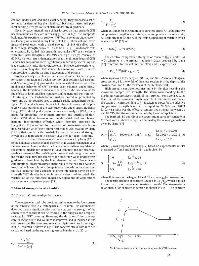
C D
A B
ε c0.0150.005εccεtc
'
fct
εtu
fcc'
βc fcc'
σc
o
Fig. 1. Stress–strain curve for concrete in rectangular CFST columns.
378 V.I. Patel et al. / Journal of Constructional Steel Research 70 (2012) 377–384
columns under axial load and biaxial bending. They proposed a set offormulas for determining the initial local buckling stresses and post-local buckling strengths of steel plates under stress gradients.
Recently, experimental research has focused on high strength CFSTbeam-columns as they are increasingly used in high rise compositebuildings. An experimental study on CFST beam-columns under eccen-tric loading was carried out by Chung et al. [12]. These columns weremade of steel tubes with a yield strength of 445 MPa filled with88 MPa high strength concrete. In addition, Liu [13] undertook testson eccentrically loaded high strength rectangular CFST beam-columnswith steel yield strength of 495 MPa and high strength concrete of60 MPa. His test results demonstrated that the ultimate loads of CFSTslender beam-columns were significantly reduced by increasing theload eccentricity ratio. Moreover, Lue et al. [14] reported experimentalresults on rectangular CFST slender beam-columns with concretecompressive strengths varying between 29 and 84 MPa.
Nonlinear analysis techniques are efficient and cost-effective per-formance simulation and design tools for CFST columns [2]. Lakshmiand Shanmugam [15] proposed a semi-analytical model for deter-mining the behavior of CFST slender beam-columns under biaxialbending. The limitation of their model is that it did not account forthe effects of local buckling, concrete confinement and concrete ten-sile strength. The load–deflection analysis procedure presented byVrcelj and Uy [16] could be used to analyze axially loaded high strengthsquare CFST slender beam-columns, but it has not considered the pro-gressive local buckling of the steel tube walls under stress gradients.Liang [17,18] developed a performance-based analysis (PBA) tech-nique for predicting the ultimate strength and ductility of thin-walled CFST short beam-columns under axial load and biaxialbending, incorporating effective width formulas proposed byLiang et al. [11] to account for the effects of progressive local buck-ling. Moreover, an efficient numerical model was created by Liang[19,20] that simulates the load–deflection responses and strengthenvelopes of high strength circular CFST slender beam-columns.
This paper extends the numericalmodels developed by Liang [17,19]to the nonlinear analysis of high strength thin-walled rectangular CFSTslender beam-columns under axial load and uniaxial bending. Materialconstitutive models for concrete in CFST columns and for structuralsteels are presented. Themodeling of cross-sectional strengths account-ing for the local buckling effects of the steel tube walls under stressgradients is formulated by the fiber element method. New efficientcomputational algorithms based on theMüller's method are developedto obtain nonlinear solutions. Computational procedures for simulatingthe load–deflection and axial load–moment interaction curves for highstrength CFST slender beam-columns are described in detail. Theverification of the numerical model developed and its applicationsare given in a companion paper [21].
2. Material stress–strain relationships
2.1. Stress–strain relationships for concrete
The rectangular steel tube provides confinement to the four cornersof the concrete core in a rectangular CFST column. This confinementdoes not have a significant effect on the compressive strength of theconcrete core so that it can be ignored in the analysis and design ofrectangular CFST columns. However, the ductility of the concretecore in rectangular CFST columns is improved and is included in theconcretemodel. The stress–strain relationship for concrete in rectangu-lar CFST columns is shown in Fig. 1. The concrete stress from O to A iscalculated based on the equations given by Mander et al. [22] as:
σ c ¼f ′ccλ
εcε′cc
� �λ−1þ εc
ε′cc
� �λ ð1Þ
λ ¼ EcEc− f ′cc
ε′cc
� � ð2Þ
where σc stands for the compressive concrete stress, fcc′ is the effectivecompressive strength of concrete, εcis the compressive concrete strain,εcc′is the strain at fcc′ and Ec is the Young's modulus of concrete whichis given by ACI [23] as
Ec ¼ 3320ffiffiffiffiffiffif ′cc
qþ 6900 MPað Þ: ð3Þ
The effective compressive strengths of concrete (fcc′) is taken asγcfc′, where γc is the strength reduction factor proposed by Liang[17] to account for the column size effect and is expressed as
γc ¼ 1:85D−0:135c 0:85≤γc≤1:0ð Þ ð4Þ
where Dcis taken as the larger of (B−2t) and (D−2t) for a rectangularcross section, B is the width of the cross-section, D is the depth of thecross-section, and t is the thickness of the steel tube wall.
High strength concrete becomes more brittle after reaching themaximum compressive strength. The strain corresponding to themaximum compressive strength of high strength concrete is greaterthan that of the normal strength concrete. In the numerical model,the strain εcc′ corresponding to fcc′ is taken as 0.002 for the effectivecompressive strength less than or equal to 28 MPa and 0.003forfcc′>82 MPa. For the effective compressive strength between 28and 82 MPa, the strain εcc′is determined by linear interpolation.
The parts AB, BC and CD of the stress–strain curve for concrete inCFST columns as shown in Fig. 1 are defined by the following equationsgiven by Liang [17]:
σ c ¼f ′cc for ε′cc bεc ≤0:005βc f
′cc þ 100 0:015−εcð Þ f
0
cc−βc f0
cc
� �for 0:005 bεc ≤0:015
βc f′‘cc for εc > 0:015
8><>: ð5Þ
where βc was proposed by Liang [17] based on experimental resultspresented by Tomii and Sakino [24] and is given by
βc ¼1:0 for
Bs
t≤ 24
1:5− 148
Bs
tfor24 b
Bs
t≤ 48
0:5 forBs
t> 48
8>>>>><>>>>>:
ð6Þ
where Bs is taken as the larger of B andD for a rectangular cross-section.The tensile strength of concrete is taken as 0:6
ffiffiffiffiffiffif ′cc
q, which is much
lower than its ultimate compressive strength. The stress–strainrelationship for concrete in tension is shown in Fig. 1. The concrete
74

B
ε
φ
y
y
D
Pn
x
y
n
e,i
t
i
n,i
Concrete fibers Steel fibers
N.A.
d
d
Load,
Fig. 3. Fiber element discretization of CFST beam-column section.
379V.I. Patel et al. / Journal of Constructional Steel Research 70 (2012) 377–384
tensile stress is considered zero at the ultimate tensile strain. Theconcrete tensile stress is directly proportional to the tensile strainof concrete up to concrete cracking. After concrete carking, the tensilestress of concrete is inversely proportional to the tensile strain ofconcrete up to the ultimate tensile strain due to concrete cracking.The ultimate tensile strain is taken as 10 times of the strain at cracking.
2.2. Stress–strain relationships for steels
Three types of the structural steels such as high strength structuralsteels, cold-formed steels and mild structural steels are considered inthe numerical model. The steel generally follows the same stress–strainrelationship under the tension and compression. The stress–strainrelationship for steel under uniaxial compression is shown in Fig. 2.The mild structural steels have a linear stress–strain relationship up tothe yield stress, however, it is assumed that high strength steels andcold-formed steels have a linear stress–strain relationship up to0.9fsy, where fsy is the steel yield strength. The rounded curve of thecold-formed structural steel can be defined by the equation proposedby Liang [17]. The hardening strain εst is assumed to be 0.005 for highstrength and cold-formed steels and 10εsy for mild structural steelsin the numerical model. The ultimate strain of steels is assumed tobe 0.2.
3. Modeling of cross-sectional strengths
3.1. Strain calculations
In thefiber elementmethod, the rectangular cross-section of a slenderbeam-column is divided into small concrete fiber elements and steelfiber elements for the purpose of the fiber element integration. Thetypical cross-section discretization is shown in Fig. 3. The strain ofeach fiber element is calculated by multiplication of the curvatureand the orthogonal distance of each fiber element from the neutralaxis. In the numerical model, the compressive strain is taken as positiveand the tensile strain is taken as negative. The strain εt at the top fiber ofthe section in the composite cross-section can be determined bymulti-plication of the curvature ϕ and the neutral axis depth dn.
For bending about the x-axis, the strains in concrete and steel fiberscan be calculated by the following equations given by Liang [17]:
yn;i ¼D2−dn ð7Þ
de;i ¼ yi−yn;i�� �� ð8Þ
Fig. 2. Stress–strain curves for structural steels.
εi ¼ϕde:i for yi≥yn;i
−ϕde;i for yibyn;i
�ð9Þ
wheredn is the neutral axis depth, de, iis the orthogonal distance from thecentroid of each fiber element to the neutral axis, yi is the coordinates ofthe fiber i and εi is the strain at the ith fiber element and yn, i is thedistance from the centroid of each fiber element to the neutral axis.
For bending about the y-axis, the strain in concrete and steel fiberscan be calculated by the following equations given by Liang [17]
xn:i ¼B2−dn ð10Þ
de:i ¼ xi−xn;i�� �� ð11Þ
εi ¼ϕde;i for xi ≥ xn;i−ϕde;i for xi b xn;i
�ð12Þ
where xi is coordinates of the fiber i and xn, i is the distance from thecentroid of each fiber element to the neutral axis.
3.2. Initial local buckling
Steel plates in thin-walled CFST columns with a large width-to-thickness ratiomay buckle locally outward, which reduces the strengthand ductility of the beam-columns. The initial local buckling stresses ofsteel plates depend on the width-to-thickness ratio, residual stresses,geometric imperfections, the yield strength of steel plates, and theapplied edge stress gradients. Liang and Uy [10] reported that localbuckling of a thin steel plate may occur when its width-to-thickness (b/t) ratio is greater than 30. Steel tube walls of a thin-walledCFST column under axial load and bending are subjected to uniform ornon-uniform stresses. Therefore, steel tube walls under both uniformand non-uniform compressive stresses must be taken into account inthe interaction buckling analysis of a thin-walled CFST beam-columnunder axial load and uniaxial bending. Liang et al. [11] proposed formulasfor determining the initial local buckling stresses of thin steel plates understress gradients. These formulas are incorporated in the numerical modelto account for initial local buckling effects on the behavior of highstrength thin-walled rectangular CFST slender beam-columns.
75

380 V.I. Patel et al. / Journal of Constructional Steel Research 70 (2012) 377–384
3.3. Post-local buckling
The post-local buckling strengths of thin steel plates can be deter-mined using the effective strength and width concept. Liang et al. [11]proposed effective strength and width formulas for determining thepost-local buckling strengths of steel plates in thin-walled CFSTbeam-columns under axial load and biaxial bending. Their formulasare incorporated in the numerical model to determine the ultimatestrengths of thin steel plates under stress gradients. Fig. 4 shows theeffective and ineffective areas of a rectangular thin-walled CFSTbeam-column cross-section under axial compression and uniaxialbending. The effective widths be1 and be2 shown in Fig. 4 are givenby Liang et al. [11] as
be1b
¼0:2777þ 0:01019
bt
� �−1:972� 10−4 b
t
� �2þ 9:605� 10−7 b
t
� �3forαs > 0:0
0:4186−0:002047bt
� �þ 5:355� 10−5 b
t
� �2−4:685� 10−7 b
t
� �3forαs ¼ 0:0
8>>><>>>:
ð13Þ
be2b
¼ 2−αsð Þ be1b
ð14Þ
where b is the clear width of a steel flange or web in a CFST columnsection, and αs=σ2/σ1, where σ2 is the minimum edge stress appliedto the plate and σ1 is the maximum edge stress applied to the plate.
3.4. Simulation of progressive post-local buckling
The behavior of a thin steel plate under increasing loads is character-ized by the progressive post-local buckling. In the post-local bucklingregime, stresses in the steel plate are gradually redistributed from theheavily buckled region to the unloaded edges. This implies that theheavily buckled central region in the plate carries lower stresses whilethe unloaded edges withstand higher stresses. The effective widthconcept assumes that a steel plate attains its ultimate strengthwhen the maximum stress in the plate reaches its yield strength. Theineffective width of a thin steel plate increases from zero to maximumvalue when the applied load is increased from the initial local bucklingload to the ultimate load. The maximum ineffective width of each thinsteel plate in a CFST beam-column at the ultimate load is determinedby
bne;max ¼ b− be1 þ be2ð Þ: ð15Þ
Ineffective steel areaEffective steel area
σ1
σ2
b e1
be2
D x
y
N.A.
B
t
Fig. 4. Effective area of steel tubular cross-section under axial load and bending.
As suggested by Liang [17], the ineffective width between zeroand bne,max can be approximately calculated using linear interpolationbased on the maximum stress level in the steel plate, and it is givenby
bne ¼σ1−σ1c
f sy−σ1c
!bne;max ð16Þ
where σ1c is the maximum edge stress in a steel tube wall when initiallocal buckling occurs.
If the maximum edge stress σ1 in a steel plate with a b/t ratiogreater than 30 is larger than the initial local buckling stress σ1c, itis assumed that steel fiber elements within the ineffective area donot carry any loads. Therefore, the normal stresses in those fibersare assigned to zero. However, if the maximum edge stress σ1 isgreater than the yield strength of the steel plate, stresses within thesteel tube wall need to be reduced by a factor of σ1/fsy to make surethat the effectivewidth concept is valid. The effective strength formulasproposed by Liang et al. [11] are employed to determine the ultimatestrength of the thin steel plate, when the total effective width of theplate (be1+be2) is greater than its width (b). If the maximum edgestress of the thin steel plate is greater than the ultimate edge stressσ1u of the steel plate, the stresses within the steel plate are reducedby a factor of σ1/σ1u.
3.5. Stress resultants
The axial force and bending moments carried by a rectangularCFST beam-column cross-section are determined as stress resultantsin the cross-section as follows:
P ¼Xnsi¼1
σ s;iAs;i þXncj¼1
σ c; jAc; j ð17Þ
Mx ¼Xnsi¼1
σ s;iAs;iyi þXncj¼1
σ c; jAc; jyj ð18Þ
My ¼Xnsi¼1
σ s;iAs;ixi þXncj¼1
σ c;jAc;jxj ð19Þ
where P is the axial force, σs, i is the stress of steel fiber i, As, i is the areaof steel fiber i, σc, j is the stress of concrete fiber j, Ac, j is the area ofconcrete fiber j, xi and yi are the coordinates of steel element i, xjand yj are the coordinates of concrete element j, ns is the total numberof steel fiber elements and nc is the total number of concrete fiberelements.
4. Müller's method algorithms
4.1. Determining the neutral axis depth
Computational algorithms based on the Müller's method [25] aredeveloped to iterate the neutral axis depth in a composite cross-sectionwith local bucking effects. The neutral axis depth dn of the compositecross-section is iteratively adjusted to maintain the force equilibriumin order to determine the internal moment carried by the section. TheMüller's method algorithm requires three initial values of the neutralaxis depth dn, 1, dn, 2 and dn, 3 to start the iterative process. The neutralaxis depth dn is adjusted by using the following proposed equations:
dn;4 ¼ dn;3 þ−2c1
b1 �ffiffiffiffiffiffiffiffiffiffiffiffiffiffiffiffiffiffiffiffiffiffiffiffib1
2−4a1c1q ð20Þ
76

381V.I. Patel et al. / Journal of Constructional Steel Research 70 (2012) 377–384
a1 ¼dn;2−dn;3� �
rpu;1−rpu;3� �
− dn;1−dn;3� �
rpu;2−rpu;3� �
dn;1−dn;2� �
dn;1−dn;3� �
dn;2−dn;3� � ð21Þ
b1 ¼dn;1−dn;3� �2
rpu;2−rpu;3� �
− dn;2−dn;3� �2
rpu;1−rpu;3� �
dn;1−dn;2� �
dn;1−dn;3� �
dn;2−dn;3� � ð22Þ
c1 ¼ rpu;3 ð23Þ
where rpu is the residual moment at the mid-height of the column that isgiven by
rpu ¼ P eþ um þ uoð Þ−Mmi ð24Þ
where uo is the initial geometric imperfection at the mid-height of thebeam-column, um is the deflection at the mid-height of the beam-column, e is the eccentricity of the applied load as shown in Fig. 5and Mmi is the internal moment carried by the section.
The sign (+ or −) of the square root term in the denominator ofEq. (20) is chosen to be the same as the sign of b1 to keep dn, 4 close todn, 3. In order to obtain converged solutions, the values of dn, 1, dn, 2 anddn, 3 and corresponding residual moments rpu, 1, rpu, 2 and rpu, 3 need tobe exchanged. The values of dn, 1, dn, 2 and dn, 3 are temporarily storedin dn, 1
T , dn, 2T and dn, 3T respectively while the values of rpu, 1, rpu, 2 and
rpu, 3 are temporarily stored in rpu, 1T , rpu, 2T and rpu, 3
T respectively. Thefollowing computer codes are executed:
IF Abs dn;4−dTn;2� �
bAbs dn;4−dTn;1� �
; dn;1 ¼ dTn;2; dn;2 ¼ dTn;1; rpu;1 ¼ rTpu;2; rpu;2 ¼ rTpu;1;h i
;
IF Abs dn;4−dTn;3� �
bAbs dn;4−dTn;2� �
; dn;2 ¼ dTn;3; dn;3 ¼ dTn;2; rpu;2 ¼ rTpu;3; rpu;3 ¼ rTpu;2;h i
;
dn;3 ¼ dn;4; rpu;3 ¼ rpu;4:
Eq. (20) and the above codes are executed repetitively until theconvergence criterion of |rpu|bεk is satisfied,where εk is the convergencetolerance that is taken as 10−4.
4.2. Determining the curvature at column ends
The maximum moment Me max at the column ends for a givenaxial load Pn needs to be determined in order to generate the axialload–moment interaction diagram for the slender beam-column.The curvature at the mid-height ϕm of the beam-column under axial
Fig. 5. Pin-ended beam-column model.
load and uniaxial bending is initialized and gradually increased. Foreach curvature increment at the mid-height of the beam-column,the curvature at the column ends ϕe is iteratively adjusted by theMüller's method algorithm to maintain equilibrium between theinternal momentMmi and the external moment Mme at the mid-heightof the beam-column. The Müller's method algorithm requires threeinitial values of the curvature at the column ends ϕe, 1, ϕe, 2 and ϕe, 3
to start the iterative process. The curvature ϕe at the column endsis adjusted by using the following proposed equations:
ϕe;4 ¼ ϕe;3 þ−2c2
b2 þffiffiffiffiffiffiffiffiffiffiffiffiffiffiffiffiffiffiffiffiffiffib22−4a2c2
q ð25Þ
a2 ¼ϕe;2−ϕe;3
� �rpm;1−rpm;3
� �− ϕe;1−ϕe;3
� �rpm;2−rpm;3
� �ϕe;1−ϕe;2
� �ϕe;1−ϕe;3
� �ϕe;2−ϕe;3
� � ð26Þ
b2 ¼ϕe;1−ϕe;3
� �2rpm;2−rpm;3
� �− ϕe;2−ϕe;3
� �2rpm;1−rpm;3
� �ϕe;1−ϕe;2
� �ϕe;1−ϕe;3
� �ϕe;2−ϕe;3
� � ð27Þ
c2 ¼ rpm;3 ð28Þ
where rpm is the residual moment at the mid-height of the columnwhich is given by
rpm ¼ Me þ Pn um þ uoð Þ−Mmi: ð29Þ
The sign of the square root term in the denominator of Eq. (25) istaken as positive in order to obtain converged solutions. Similar to thedetermination of dn, the values of ϕe, 1, ϕe, 2 and ϕe, 3 and correspondingrpm, 1, rpm, 2 and rpm, 3 need to be exchanged in order to obtain the trueϕe.The values of ϕe, 1, ϕe, 2 and ϕe, 3 are temporarily stored in ϕe, 1
T , ϕe, 2T and
ϕe, 3T respectively and the values of rpm, 1, rpm, 2 and rpm, 3 are temporarily
stored in rpm, 1T , rpm, 2
T and rpm, 3T respectively. The following computer
codes are executed:
IF Abs ϕe;4−ϕTe;2
� �bAbs ϕe;4−ϕT
e;1
� �; ϕe;1 ¼ ϕT
e;2;ϕe;2 ¼ ϕTe;1; rpm;1 ¼ rTpm;2; rpm;2 ¼ rTpm;1;
h i;
IF Abs ϕe;4−ϕTe;3
� �bAbs ϕe;4−ϕT
e;2
� �; ϕe;2 ¼ ϕT
e;3;ϕe;3 ¼ ϕTe;2; rpm;2 ¼ rTpm;3; rpm;3 ¼ rTpm;2;
h i;
ϕe;3 ¼ ϕe;4; rpm;3 ¼ rpm;4:
The curvature at the column ends is iteratively adjusted untilconvergence criterion of |rpm|bεk is satisfied.
5. Modeling of load–deflection responses
5.1. Formulation
A new efficient numerical model has been developed to generateaxial load–deflection curves for high strength thin-walled rectangularCFST slender beam-columns under axial load and uniaxial bendingwith local buckling effects. The deflected shape of the column is as-sumed to be part of a sine wave as suggested by Shakir–Khalil andZeghiche [2]. The deflection at any point (y, z) along the columnlength is given by
u ¼ um sinπzL
� �ð30Þ
where L is the effective length of the beam-column.
77

Fig. 6. Flowchart for determining the axial load–deflection curve for rectangular thin-walled CFST slender columns.
382 V.I. Patel et al. / Journal of Constructional Steel Research 70 (2012) 377–384
The curvature (ϕ) along the length of the beam-column can bederived from Eq. (30) as
ϕ ¼ ∂2u∂z2
¼ πL
� �2um sin
πzL
� �: ð31Þ
The curvature at the mid-height of the beam-column is given by
ϕm ¼ πL
� �2um ð32Þ
The external bending moment at the mid-height of the beam-column with an initial geometric imperfection uo and under eccentricloading can be calculated by
Mme ¼ P eþ um þ uoð Þ ð33Þ
5.2. Analysis procedure
The axial load–deflection analysis procedure is started by first as-suming a small value of the mid-height deflection um in the slenderbeam-column under axial load with an eccentricity. The curvatureϕm at the mid-height of the slender beam-column is calculated forthe given mid-height deflection using Eq. (32). The proposed Müller'smethod algorithms are used to adjust the neutral axis depth in thecomposite cross-section tomaintain the force equilibrium. The internalbending moment Mmi is determined using the moment-curvatureresponse of the composite cross-section with local buckling effects.The mid-height deflection of the slender beam-column is graduallyincreased and the process is repeated. A pair of applied axial loadand deflection is used to plot the axial load–deflection diagram.The flowchart of the axial load–deflection analysis procedure isshown in Fig. 6. The key steps of the axial load–deflection diagramare given as follows:
(1) Input the dimensions of the beam-column, material propertiesof the steel and concrete, the loading eccentricity e and initialgeometric imperfection uo.
(2) Divide the concrete core and steel tube into fiber elements.(3) Initialize the mid-height deflection: um=Δum.(4) Compute the curvature ϕm at the mid-height of the beam-
column from the given mid-height deflection um by usingEq. (32).
(5) Initialize three values of the neutral axis depth of the compositecross-section: dn, 1=D/4, dn, 2=D/2 and dn, 3=D.
(6) Compute the stresses of steel and concrete using the stress–strainrelationships.
(7) Check local buckling and redistribute stresses in steel fibers iflocal buckling occurs.
(8) Calculate the internal bending moment Mmi and the externalbending moment Mme corresponding to dn, 1=D/4, dn, 2=D/2and dn, 3=D respectively.
(9) Compute the residualmoments rpu, 1, rpu, 2 and rpu, 3 correspondingtodn, 1=D/4, dn, 2=D/2 and dn, 3=D respectively.
(10) Calculate a1, b1 and c1 and adjust the neutral axis depth dnusing Eq. (20).
(11) Compute fiber element stresses and redistribute normal stressesin steel fibers if local buckling occurs.
(12) Calculate the internal bendingmomentMmi and external bendingmoment Mme corresponding to the neutral axis depth dn.
(13) Compute rpu using Eq. (24) and repeat Steps (10)–(12) untilthe convergence condition |rpu|bεk is satisfied.
(14) Increase the deflection um at the mid-height of the beam-column and repeat steps (4)–(13) until the ultimate load Pnis obtained or the deflection limit is reached.
(15) Plot the load–deflection curve.
The convergence tolerance εk is set to 10−4 in the analysis. Thecomputational procedure proposed can predict the complete axialload–deflection responses of uniaxially loaded rectangular CFST slenderbeam-columns with local buckling effects.
6. Modeling of axial load–moment interaction diagrams
6.1. Formulation
The ultimate bending moment Mn is calculated as the maximumapplied moment Me max at the column ends for a given axial load Pnto generate the axial load–moment interaction diagram. The maxi-mum moment Me max is obtained when the external moment Mme at-tains the ultimate bending strength of the beam-column cross-section for the given axial load Pn. The curvature at the column endsis adjusted using the Müller's method algorithms and the correspond-ing moment Me at the column ends is calculated. The external
78

Start
End
Input data
Divide composite section into fibers
Compute Poa using P-u analysis procedure including local buckling effects
Initialize
Initialize
Calculate um using Eq.(35)
Calculate Mmi using P-M- relationship accounting for local buckling effects
Initialize Compute
Adjust using Eq.(25)
Calculate Mmi and Me using P-M-relationship considering local buckling
effects
Is Pn < Poa?
Plot Pn-Mn diagram
Is Mn obtained?
Yes
No
No
NoYes
Yes
mm φφ Δ=
0=nP
φ
φ
eφ
mmm φφφ Δ+=
nnn PPP Δ+=
?kpmr ε<
,61,101 3,1, −=−= EE ee φφ3,2,1, ,, pmpmpm rrr( ) 23,1,2, eee φφφ +=
Fig. 7. Flowchart for determining the axial load–moment interaction diagram forrectangular thin-walled CFST slender beam-columns.
383V.I. Patel et al. / Journal of Constructional Steel Research 70 (2012) 377–384
moment at the mid-height of the slender beam-column is calculatedby
Mme ¼ Me þ Pn um þ uoð Þ: ð34Þ
The curvature at the mid-height of the slender beam-column isgradually increased to calculate the maximum bending moment Me max
for a given axial load. For each curvature increment at the mid-height of the beam-column, the mid-height deflection is calculatedby the following equation:
um ¼ Lπ
� �2ϕm: ð35Þ
6.2. Analysis procedure
The axial load–moment interaction diagram for high strengththin-walled rectangular CFST slender beam-column is determinedby the numerical model developed. The axial load–deflection analysisprocedure incorporating local buckling effects is used to determinethe ultimate axial load Poa of the slender column under axial loadalone. The applied axial load Pn is gradually increased. The curvatureϕm at the mid-height is initialized and gradually increased. Theload–moment–curvature relationship incorporating local bucklingeffects is used to determine the corresponding internal momentMmi at the mid-height of the beam-column. The proposed Müller'smethod algorithms are used to adjust the curvature ϕe at the columnends to produce themomentMe that satisfies equilibrium at themid-height of the beam-column. The maximum moment Me max at thecolumn ends is obtained for each increment of the applied axialload Pn. A pair of the maximum moment Me max at the column endsand the given applied axial load Pn is used to plot the axial load–momentinteraction diagram. Fig. 7 shows the flowchart for determining axialload–moment interaction diagrams for rectangular CFST slenderbeam-column. The main steps of the analysis procedure are givenas follows:
(1) Input the geometry of the beam-column, material properties ofthe steel and concrete and the initial geometric imperfectionuo.
(2) Divide composite section into concrete and steel fiber elements.(3) Compute the ultimate axial load Poa of the axially loaded slender
beam-column using the load–deflection analysis procedureaccounting for local buckling effects.
(4) Initialize the applied axial load: Pn=0.(5) Initialize the curvature at the mid-height of the beam-column:
ϕm=Δϕm.(6) Calculate the mid-height deflection um using Eq. (35) from the
mid-height curvature ϕm.(7) Compute the internal moment Mmi for the given axial load Pn
using the P−M−ϕ relationship accounting for local bucklingeffects.
(8) Initialize three values of the curvature at the column endsϕe, 1=10−10, ϕe, 3=10−6, ϕe, 2=(ϕe, 1+ϕe, 3)/2 and calculatethe corresponding rpm, 1, rpm, 2 and rpm, 3.
(9) Calculate a2, b2 and c2 and adjust the curvature at the columnsend φe using Eq. (25).
(10) Compute the moment Me at the column ends and the internalbendingmomentMmi using the P−M−ϕ relationship accountingfor local buckling effects.
(11) Calculate rpm using Eq. (29) and repeat steps (9)–(10) until|rpm|bεk.
(12) Increase the curvature at the mid-height of the beam-columnby ϕm=ϕm+Δϕm.
(13) Repeat steps (6)–(12) until the ultimate bending strengthMn(=Me max) at the column ends is obtained.
(14) Increase the axial load by Pn=Pn+ΔPn, where ΔPn=Poa/10.(15) Repeat steps (5)–(14) until the maximum load increment is
reached.(16) Plot the axial load–moment interaction diagram.
Numerical analysis shows that the proposed Muller algorithms arevery efficient for obtaining converged solutions. The ultimate pureaxial load Poa is calculated by specifying the eccentricity of the appliedto zero in the axial load–deflection analysis. Similarly, the ultimate purebending strength of a slender beam-column is obtained by specifyingthe axial load to zero in the axial load–moment interaction strengthanalysis.
7. Conclusions
This paper has presented a new numerical model for simulatingthe behavior of high strength thin-walled rectangular CFST slenderbeam-columns under axial load and uniaxial bending. The effects of
79

384 V.I. Patel et al. / Journal of Constructional Steel Research 70 (2012) 377–384
local buckling, column slenderness, eccentricity of loading, highstrength materials, initial geometric imperfections and material andgeometric nonlinearities are considered in the numerical modeldeveloped. The numerical model for pin-ended CFST slender beam-columns with equal end eccentricities and single curvature bendingwas developed based on fiber element formulations. New Müller'smethod algorithms were developed to iterate the neutral axis depthin the composite cross-section and to adjust the curvature at thecolumn ends in the slender beam-column to satisfy equilibriumconditions. The new numerical model is shown to be efficient forpredicting the complete axial load–deflection and axial load–momentinteraction curves for high strength thin-walled rectangular CFSTslender beam-columns with local buckling effects. The comparisonwith corresponding experimental results and parametric studies isgiven in a companion paper.
References
[1] Bridge RQ. Concrete filled steel tubular columns. School of Civil Engineering,University of Sydney, Sydney, Australia, Research Report No. R283; 1976.
[2] Shakir-KhalilH, Zeghiche J. Experimental behaviour of concrete-filled rolled rectangularhollow-section columns. The Structural Engineer 1989;67(19):346–53.
[3] Matsui C, Tsuda K, Ishibashi Y. Slender concrete filled steel tubular columns undercombined compression and bending. The 4th Pacific Structural Steel ConferenceSingapore, Pergamon 3(10): 1995. p. 29–36.
[4] Schneider SP. Axially loaded concrete-filled steel tubes. J Struct Eng ASCE1998;124(10):1125–38.
[5] Han LH. Tests on stub columns of concrete-filled RHS sections. J Constr Steel Res2002;58(3):353–72.
[6] Ellobody E, Young B, Lam D. Behaviour of normal and high strength concrete-filledcompact steel tube circular stub columns. J Constr Steel Res 2006;62(7):706–15.
[7] Ge H, Usami T. Strength of concrete-filled thin-walled steel box columns: experiment.J Struct Eng ASCE 1992;118(11):3036–54.
[8] Bridge RQ, O'Shea MD. Behaviour of thin-walled steel box sections with or withoutinternal restraint. J Constr Steel Res 1998;47(1–2):73–91.
[9] Uy B. Strength of concrete filled steel box columns incorporating local buckling.J Struct Eng ASCE 2000;126(3):341–52.
[10] Liang QQ, Uy B. Theoretical study on the post-local buckling of steel platesin concrete-filled box columns. Computers and Structures 2000;75(5):479–90.
[11] Liang QQ, Uy B, Liew JYR. Local buckling of steel plates in concrete-filled thin-walled steel tubular beam-columns. J Constr Steel Res 2007;63(3):396–405.
[12] Chung J, Tsuda K, Matsui C. High-strength concrete filled square tube columnssubjected to axial loading. The Seventh East Asia-Pacific Conference on StructuralEngineering & Construction, Kochi, Japan, vol. 2; 1999. p. 955–60.
[13] Liu D. Behaviour of eccentrically loaded high-strength rectangular concrete-filledsteel tubular columns. J Constr Steel Res 2006;62(8):839–46.
[14] Lue DM, Liu JL, Yen T. Experimental study on rectangular CFT columns with high-strength concrete. J Constr Steel Res 2007;63(1):37–44.
[15] Lakshmi B, Shanmugam NE. Nonlinear analysis of in-filled steel-concrete compositecolumns. J Struct Eng ASCE 2002;128(7):922–33.
[16] Vrcelj Z, Uy B. Strength of slender concrete-filled steel box columns incorporatinglocal buckling. J Constr Steel Res 2002;58(2):275–300.
[17] Liang QQ. Performance-based analysis of concrete-filled steel tubular beam-columns, Part I: theory and algorithms. J Constr Steel Res 2009;65(2):363–72.
[18] Liang QQ. Strength and ductility of high strength concrete-filled steel tubularbeam-columns. J Constr Steel Res 2009;65(3):687–98.
[19] Liang QQ. High strength circular concrete-filled steel tubular slender beam-columns, Part I: numerical analysis. J Constr Steel Res 2011;67(2):164–71.
[20] Liang QQ. High strength circular concrete-filled steel tubular slender beam-columns, Part II: fundamental behavior. J Constr Steel Res 2011;67(2):172–80.
[21] Patel VI, Liang QQ, Hadi MNS. High strength thin-walled rectangular concrete-filled steel tubular slender beam-columns, Part II: behavior. Journal of Construc-tional Steel Research 2012;70(C):368–76.
[22] Mander JB, PriestlyMNJ, Park R. Theoretical stress–strainmodel for confined concrete.J Struct Eng ASCE 1988;114(8):1804–26.
[23] ACI-318. Building code requirements for reinforced concrete. Detroit, MI: ACI;2002.
[24] Tomii M, Sakino K. Elastic–plastic behavior of concrete filled square steel tubularbeam-columns. Trans Architec Inst Jpn 1979;280:111–20.
[25] Müller DE. A method for solving algebraic equations using an automatic computer.MTAC 1956;10:208–15.
80

Journal of Constructional Steel Research 70 (2012) 368–376
Contents lists available at SciVerse ScienceDirect
Journal of Constructional Steel Research
High strength thin-walled rectangular concrete-filled steel tubular slenderbeam-columns, Part II: Behavior
Vipulkumar Ishvarbhai Patel a, Qing Quan Liang a,⁎, Muhammad N.S. Hadi b
a School of Engineering and Science, Victoria University, PO Box 14428, Melbourne, VIC 8001, Australiab School of Civil, Mining and Environmental Engineering, University of Wollongong, Wollongong, NSW 2522, Australia
⁎ Corresponding author. Tel.: +61 3 9919 4134; fax:E-mail address: [email protected] (Q.Q. Liang).
0143-974X/$ – see front matter © 2011 Elsevier Ltd. Aldoi:10.1016/j.jcsr.2011.10.021
a b s t r a c t
a r t i c l e i n f oArticle history:Received 5 April 2011Accepted 18 October 2011Available online 13 November 2011
Keywords:Concrete-filled steel tubesHigh strength materialsLocal and post-local bucklingNonlinear analysisSlender beam-columns
Experimental and numerical research on full-scale high strength thin-walled rectangular steel slender tubesfilled with high strength concrete has not been reported in the literature. In a companion paper, a new nu-merical model was presented that simulates the nonlinear inelastic behavior of uniaxially loaded highstrength thin-walled rectangular concrete-filled steel tubular (CFST) slender beam-columns with local buck-ling effects. The progressive local and post-local buckling of thin steel tube walls under stress gradients wasincorporated in the numerical model. This paper presents the verification of the numerical model developedand its applications to the investigation into the fundamental behavior of high strength thin-walled CFSTslender beam-columns. Experimental ultimate strengths and load-deflection responses of CFST slenderbeam-columns tested by independent researchers are used to verify the accuracy of the numerical model.The verified numerical model is then utilized to investigate the effects of local buckling, column slendernessratio, depth-to-thickness ratio, loading eccentricity ratio, concrete compressive strengths and steel yieldstrengths on the behavior of high strength thin-walled CFST slender beam-columns. It is demonstratedthat the numerical model is accurate and efficient for determining the behavior of high strength thin-walled CFST slender beam-columns with local buckling effects. Numerical results presented in this studyare useful for the development of composite design codes for high strength thin-walled rectangular CFSTslender beam-columns.
© 2011 Elsevier Ltd. All rights reserved.
1. Introduction
The behavior of high strength thin-walled rectangular concrete-filledsteel tubular (CFST) slender beam-columns under axial load and bendingis influenced by many parameters such as the depth-to-thickness ratio,loading eccentricity, column slenderness, concrete compressive strength,steel yield strength, initial geometric imperfections and second order ef-fects. Thin-walled CFST slender beam-columns under eccentric loadingmay fail by local and overall buckling. Researches on the interactionlocal and overall buckling behavior of high strength CFST slender beam-columns have been comparatively very limited. No design specificationson the design of high strength thin-walled CFST slender beam-columnsare given in current design codes such as Eurocode 4 [1], LRFD [2] andACI 318-05 [3]. Apparently, the fundamental behavior of high strengththin-walled CFST slender beam-columns with large depth-to-thicknessratios has not been fully understood and effective design methods havenot been developed and incorporated in current composite designcodes. In this paper, a numerical model developed is validated and
+61 3 9919 4139.
l rights reserved.
employed to investigate the behavior of high strength thin-walled CFSTslender beam-columns with local buckling effects.
The local instability problem of CFST slender beam-columns wasnot identified in early experimental researches undertaken by Bridge[4] and Shakir-Khalil and Zeghiche [5]. Their test results indicatedthat all tested normal strength CFST slender columns with a depth-to-thickness ratio (D/t) of 20 or 24 failed by overall buckling withoutthe occurring of local buckling. Local buckling of the steel tubes wasexpected in CFST columns with a D/t ratio greater than 35 as thosetested by Matsui et al. [6]. Chung et al. [7] and Zhang et al. [8] testedhigh strength CFST slender beam-columns with D/t ratios rangingfrom 31 to 52 and compressive concrete cube strength of 94.1 MPa.Han [9] carried out tests on the flexural behavior of normal strengthCFST members with D/t ratios ranging from 20 to 51. Further testson CFST columns were conducted by Vrcelj and Uy [10], Varma etal. [11] and Giakoumelis and Lam [12]. However, the behavior ofhigh strength rectangular steel tubular slender beam-columns filledwith high strength concrete has not been investigated.
In design practice, the axial load–moment interaction diagramsneed to be developed and are used to check for the strength adequacyof CFST slender beam-columns under axial load and bending. Most ofthe experiments conducted were to measure the load–deflection re-sponses of CFST slender columns. It is highly expensive and time
81

369V.I. Patel et al. / Journal of Constructional Steel Research 70 (2012) 368–376
consuming to obtain complete axial load–moment interaction curvesfor CFST slender beam-columns by experimental methods. Althoughthe load–deflection analysis procedures such as those presented byVrcelj and Uy [10] and Lakshmi and Shanmugam [13] can be usedto develop strength envelopes by varying the loading eccentricity,they are not efficient when the loading eccentricity is large. Despiteof this, the axial load–moment interaction diagrams of high strengthrectangular CFST slender beam-columns have not been studied byVrcelj and Uy [10] and Lakshmi and Shanmugam [13]. Ellobody andYoung [14] used the finite element program ABAQUS to study theaxial load–strain behavior of CFST short columns. Liang [15,16] uti-lized his numerical models to investigate the effects of various impor-tant parameters on the axial load–moment interaction curves forthin-walled CFST short beam-columns under axial load and biaxialbending. Moreover, Liang [17,18] studied concrete confinement ef-fects on column curves and axial load–moment interaction curvesfor high strength circular CFST slender beam-columns.
Presented in this paper is the verification of the numerical modeldeveloped in a companion paper [19] and the behavior of highstrength thin-walled CFST slender beam-columns with local bucklingeffects. Firstly, the numerical model is verified against existing exper-imental results. An extensive parametric study is then undertaken toinvestigate the effects of various important parameters on the ulti-mate strengths, load–deflection responses and axial load–momentinteraction diagrams of high strength thin-walled CFST slenderbeam-columns. Benchmark numerical results obtained from the para-metric study are presented and discussed.
2. Verification of the numerical model
The efficiency and accuracy of the developed numerical model aredemonstrated through comparisons between the numerical andexisting experimental results for a large number of slender beam-columns with different parameters. The ultimate axial and bendingstrengths and load–deflection curves of CFST slender beam-columnsare considered in the verification of the numerical model developed.
2.1. Ultimate axial strengths of normal strength CFST columns
The geometry, material properties and experimental results ofnormal strength CFST slender columns tested by various researchersare given in Table 1. Specimens SCH-1, SCH-2 and SCH-7 were testedby Bridge [4]. The width (B) of the steel tubes varied between
Table 1Ultimate axial strengths of normal strength CFST slender beam-columns.
Specimens B×D× t (mm) D/t L (mm) ex (mm) ey (mm) uo (mm) f
SCH-1 203.7×203.9×9.96 20 2130 0 38 1.19 2SCH-2 204.0×203.3×10.01 20 3050 0 0 1.40 3SCH-7 152.5×152.3×6.48 24 3050 0 38 0.51 3R1 80×120×5 24 3210 0 0 3R2 80×120×5 24 3210 0 24 3R5 80×120×5 24 2940 40 0 3S1 149.8×149.8×4.27 35 2700 0 0 3S2 149.8×149.8×4.27 35 2700 0 25 3S3 149.8×149.8×4.27 35 2700 0 75 3S4 149.8×149.8×4.27 35 2700 0 125 3S5 149.8×149.8×4.27 35 3600 0 0 3S6 149.8×149.8×4.27 35 3600 0 25 3S7 149.8×149.8×4.27 35 3600 0 75 3S8 149.8×149.8×4.27 35 3600 0 125 3S9 149.8×149.8×4.27 35 4500 0 0 3S10 149.8×149.8×4.27 35 4500 0 25 3S11 149.8×149.8×4.27 35 4500 0 75 3S12 149.8×149.8×4.27 35 4500 0 125 3MeanStandard deviation (SD)Coefficient of variation (COV)
152.5 mm and 204.0 mm while the depth (D) of the steel tubes ran-ged from 152.3 to 203.9 mm. The depth-to-thickness ratios (D/t) ran-ged from 20 to 24 while the length of the columns was either2130 mm or 3050 mm. Specimen SCH-2 was tested under a concen-tric axial load. Initial geometric imperfections (uo) at the mid-heightof the specimens were measured as shown in Table 1. The axial loadwas applied at an eccentricity (e) of either 38 mm or 64 mm. Theslender beam-columns were constructed by steel tubes filled withnormal strength concrete of either 29.9 or 31.1 MPa. The steel yieldstrengths (fsy) varied between 254 MPa and 291 MPa. The ultimatetensile strength (fsu) of steel tubes was assumed to be 410 MPa. TheYoung's modulus (Es) of the steel material was 205 GPa.
Specimens R1, R2 and R5 shown in Table 1 were tested by Shakir-Khalil and Zeghiche [5]. These slender beam-columns with a cross-section of 80×120 mm were constructed by cold-formed steel tubesfilled with normal strength concrete. The yield strength of the steeltubes ranged from 343.3 MPa to 386.3 MPa while the compressivestrength of concrete varied between 34 MPa and 37.4 MPa. Speci-mens were fabricated from 5 mm thick steel tubes so that theirdepth-to-thickness ratio (D/t) was 24. The effective buckling lengthsof the beam-columns were 3210 mm and 2940 mm about the majorand minor axes respectively. The ultimate tensile strength of thesesteel tubes was assumed to be 430 MPa. Specimen R1 was testedunder a concentric axial load while other specimens were testedunder eccentric loads about either the major or minor axis. The load-ing eccentricity ratios (e/D) were in the range of 0.0 to 0.5. The initialgeometric imperfections of specimens were not measured. Shakir-Khalil and Zeghiche [5] realized that the tested columns had initialgeometric imperfections that should be recorded before testing.Therefore, the initial geometric imperfections of L/1000 at the mid-height of the columns were taken into account in the present study.
Slender columns tested byMatsui et al. [6]were also considered in thisstudy. Test parameters of specimens designated by series S1 to S12 arepresented in Table 1. The columns had a square cross-section of149.8 mm wide and 4.27 mm thick. Steel tubes with yield strength of445 MPa were filled with normal strength concrete of 31.9 MPa. The ec-centricity of the applied axial load varied from zero to a maximum of125 mm. The length of the columns varied from 600mm to 4500 mmcovering a wide range of column slenderness. However, only slender col-umnswere considered in this paper. Specimens S1, S5 and S9were testedunder concentric axial loads. Experimental and analytical studies con-ducted by Matsui et al. [6] indicated that these specimens had significantgeometric imperfections that were not recorded. The initial geometric
′c (MP) fsy (MPa) fsu (MPa) Es (GPa) Pu. exp (kN) Pu. num (kN) Pu:numPu:exp
Ref.
9.9 291 410 205 1956 1995.73 1.02 [4]1.1 290 410 205 2869 2907.4 1.011.1 254 410 205 680 734.0 1.087.4 386.3 430 205 600 600.41 1.00 [5]4.0 386.3 430 205 393 383.61 0.986.6 343.3 430 205 210 216.24 1.031.9 445 498 200 1355 1356.99 1.00 [6]1.9 445 498 200 847 868.80 1.031.9 445 498 200 552 542.20 0.981.9 445 498 200 383 393.13 1.031.9 445 498 200 1143 1140.86 1.001.9 445 498 200 706 734.41 1.041.9 445 498 200 440 464.39 1.061.9 445 498 200 325 346.85 1.071.9 445 498 200 909 895.88 0.991.9 445 498 200 588 602.78 1.031.9 445 498 200 374 394.64 1.061.9 445 498 200 278 302.98 1.09
1.030.030.03
82

370 V.I. Patel et al. / Journal of Constructional Steel Research 70 (2012) 368–376
imperfections of L/1000 at the mid-height of the tested specimens wereconsidered in the present numerical analysis of these specimens.
The load–deflection analysis procedure developed by Patel et al.[19] was used to predict the ultimate strengths of these tested speci-mens. Test results indicated that specimen R1 did not attain its ulti-mate strength so that the measured maximum compressiveconcrete strain was used in the numerical analysis to determine themaximum load. The computational and experimental ultimate axialstrengths of normal strength CFST slender beam-columns are givenin Table 1, where Pu. exp represents the experimental ultimate axialstrength and Pu. num denotes the ultimate axial strength predicted bythe numerical model. It can be seen from Table 1 that the predictedultimate axial strengths of tested specimens are in good agreementwith experimental results. The mean ultimate axial strength pre-dicted by the numerical model is 1.03 times the experimental valuewith a standard deviation of 0.03 and a coefficient of variation of 0.03.
2.2. Ultimate axial strengths of high strength CFST columns
Table 2 presents the geometries, material properties and experi-mental results of high strength CFST slender columns tested by inde-pendent researchers. Chung et al. [7] tested a number of high strengthCFST slender beam-columns subjected to axial load and uniaxialbending. The specimens were designated by series C18, C24 andC30. The lengths of specimens C18, C24 and C30 were 2250, 3000and 3750 mm respectively. All specimens had a square cross-sectionof 125×125 mm. The steel tubes with yield strength of 450 MPawere filled with high strength concrete of 94.1 MPa. The tensilestrength of the steel tubes was measured as 528 MPa. The depth-to-thickness ratio (D/t) of these specimens was 39. Specimens C30-0 was tested under a concentric axial load while other columnswere subjected to axial loads at an eccentricity of either 20.5 mm or61.5 mm.
Specimens CCH1, CCH2, CCM1 and CCM2 shown in Table 2 weretested by Vrcelj and Uy [10]. These columns were made of hot-rolled steel tubes which were cut into 1770 mm length. In order tosimulate pinned-end support conditions, the specimen was providedwith special knife-edge supports secured at their ends. The loadingeccentricity ratio (e/D) was approximately equal to 0.05. The concretecompressive strength was either 52 MPa or 79 MPa while the steelyield strength was either 400 MPa or 450 MPa.
The load–deflection analysis procedure [19] was used to deter-mine the ultimate axial strengths of these high strength specimenstested. The initial geometric imperfections of these high strengthCFST slender beam-columns were not measured. However, real CFSTslender beam-columns particularly small-scale ones usually have ini-tial geometric imperfections. Therefore, the initial geometric imper-fections of L/1000 at the mid-height of the columns were taken intoaccount in the present numerical analysis of these columns. The
Table 2Ultimate axial strengths of high strength CFST slender beam-columns.
Specimens B×D× t (mm) D/t L (mm) ex (mm) ey (mm) f′c (MP)
C18-1 125×125×3.2 39 2250 0 20.5 94.1C18-3 12×125×3.2 39 2250 0 61.5 94.1C24-0 125×125×3.2 39 3000 0 0 94.1C24-1 125×125×3.2 39 3000 0 20.5 94.1C24-3 125×125×3.2 39 3000 0 61.5 94.1C30-0 125×125×3.2 39 3750 0 0 94.1CCH1 75×75×3 25 1770 0 3.75 79CCH2 65×65×3 22 1770 0 3.25 79CCM1 75×75×3 25 1770 0 3.75 52CCM2 65×65×3 22 1770 0 3.25 52MeanStandard deviation (SD)Coefficient of variation(COV)
ultimate axial strengths of these specimens obtained from the numer-ical analysis and experiments are given in Table 2. It is seen that thenumerical model predicts very well the ultimate axial strengths ofhigh strength CFST slender beam-columns. The ratio of the mean ulti-mate axial strength computed by the numerical model to the experi-mental value is 1.01. The standard deviation of Pu. num/Pu. exp is 0.07and the coefficient of variation is 0.07.
2.3. Ultimate bending strengths
Experimental results presented by Bridge [4], Shakir-Khalil andZeghiche [5], Matsui et al. [6] and Chung et al. [7] were used toexamine the accuracy of the axial–load moment interaction strengthanalysis program [19]. The initial geometric imperfections of L/1000at the mid-height of the columns were taken into account in the anal-ysis of the specimens tested by Shakir-Khalil and Zeghiche [5], Matsuiet al. [6] and Chung et al. [7]. The ultimate axial loads obtained fromexperiments were applied in the numerical analysis to determinethe ultimate bending strengths. The experimental and numericalultimate bending strengths are presented in Table 3. Theexperimental ultimate bending strength Mn. exp was calculated asMn. exp=Pn. exp×e. It appears from Table 3 that the numerical modelyields accurate predictions of the ultimate bending strengths of highstrength CFST slender beam-columns. The ratio of the mean ultimatebending strength computed by the numerical model to the experi-mental value is 1.03 with the standard deviation of 0.05 and the coef-ficient of variation of 0.05.
2.4. Load–deflection curves
The load–deflection curves for CFST slender beam-columns pre-dicted by the numerical model are compared with experimental re-sults provided by Bridge [4], Shakir-Khalil and Zeghiche [5] andMatsui et al. [6]. Fig. 1 shows the load–deflection curves for specimenSCH2 predicted by the numerical model developed by Patel et al. [19]and obtained from the experiments conducted by Bridge [4]. It can beobserved that the load–deflection curve predicted by the numericalmodel agrees reasonably well with the experimental results. The ini-tial stiffness of the load–deflection curve predicted by the model isslightly higher than that of the experimental one. This is likely attrib-uted to the uncertainty of the actual concrete stiffness and strength asthe average concrete compressive strength was used in the numericalanalysis. However, it can be seen from Fig. 1 that the numerical load–deflection curve is in excellent agreement with experimental resultsin the ultimate load range. The predicted and experimental axialload–deflection curves for specimen R5 tested by Shakir-Khalil andZeghiche [5] are depicted in Fig. 2. The figure shows that the initialstiffness of the specimen predicted by the numerical model is almostthe same as that of the experimental one up to loading level about
fsy (MPa) fsu (MPa) Es (GPa) Pu. exp (kN) Pu. num (kN) Pu:numPu:exp
Ref.
450 528 200 830 874.28 1.05 [7]450 528 200 457 490.57 1.07450 528 200 1079 1108.18 1.03450 528 200 664 676.12 1.02450 528 200 375 399.06 1.06450 528 200 747 814.05 1.09450 530 193.7 414 393.61 0.95 [10]400 530 189.3 294 263.12 0.89450 530 193.7 343 355.98 1.04400 530 189.3 269 242.59 0.90
1.010.070.07
83

Table 3Ultimate bending strengths of rectangular CFST slender beam-columns under eccentric loading.
Specimens B×D× t (mm) D/t L (mm) ex (mm) ey (mm) uo (mm) fc' (MP) fsy (MPa) fsu (MPa) Es (GPa) Mn. exp (kNm) Mn. num (kNm) Mn:num
Mn: expRef.
SCH-1 203.7×203.9×9.96 20 2130 0 38 1.19 29.9 291 410 205 74.33 79.12 1.06 [4]R2 80×120×5 24 3210 0 24 34.0 386.3 430 205 9.43 8.76 0.93 [5]R5 80×120×5 24 2940 40 0 36.6 343.3 430 205 8.4 8.82 1.05S2 149.8×149.8×4.27 35 2700 0 25 31.9 445 498 200 21.18 22.85 1.08 [6]S3 149.8×149.8×4.27 35 2700 0 75 31.9 445 498 200 41.4 39.99 0.97S4 149.8×149.8×4.27 35 2700 0 125 31.9 445 498 200 47.88 49.57 1.04S10 149.8×149.8×4.27 35 4500 0 25 31.9 445 498 200 14.7 15.89 1.08C24-1 125×125×3.2 39 3000 0 20.5 94.1 450 528 200 13.61 14.29 1.05 [7]Mean 1.03Standard deviation (SD) 0.05Coefficient of variation (COV) 0.05
371V.I. Patel et al. / Journal of Constructional Steel Research 70 (2012) 368–376
100 kN. After this loading, the stiffness of the specimen obtained fromtests slightly differs from numerical predictions. This is likely attribut-ed to the uncertainty of the concrete stiffness and strength. The nu-merical model was able to predict the post-peak behavior of thetested specimen R5.
Fig. 3 presents a comparison between numerical and experimentalaxial load–deflection curves for specimen S3. It is seen that the stiff-ness of the column predicted by the numerical model is in excellentagreement with experimental data for loading up to the ultimateload. In the post-peak range, the numerical model also predicts wellthe stiffness of the tested specimen but the predicted load capacityis lower than the test data. The verification shows that the numericalmodel yields good predictions of the ultimate axial and bendingstrengths and axial load–deflection curves for normal and highstrength CFST slender beam-columns.
3. Parametric study
An extensive parametric study was performed to investigate theinfluences of local buckling of the steel tube, column slendernessratio, depth-to-thickness ratio, eccentricity ratio, concrete compres-sive strengths and steel yield strengths on the fundamental behaviorof full-scale high strength thin-walled rectangular CFST slenderbeam-columns under axial load and uniaxial bending. Only one vari-able was considered at a time to assess its individual effect.
3.1. Influences of local buckling
The numerical model was employed to study the effects of localbuckling on the behavior of high strength rectangular CFST slender
0
500
1000
1500
2000
2500
3000
3500
0 1 2 3 4
Axi
al lo
ad (
kN)
Mid-height deflection um (mm)
Experiment
Numerical analysis
Fig. 1. Comparison of predicted and experimental axial load–deflection curves for spec-imen SCH-2.
beam-columns. A thin-walled CFST beam-column with a cross-section of 700×700 mm was considered. The thickness of the steeltube was 7 mm so that its depth-to-thickness ratio (D/t) was 100.The yield and tensile strengths of the steel tube were 690 MPa and790 MPa respectively while its Young's modulus was 200 GPa. Highstrength concrete with compressive strength of 70 MPa was filledinto the steel tube. The column slenderness ratio (L/r) was 40. Theaxial load was applied at an eccentricity 70 mm so that the loadingeccentricity ratio (e/D) was 0.1. The initial geometric imperfectionat the mid-height of the beam-column was assumed to be L/1500.The slender beam-column was analyzed by considering and ignoringlocal buckling effects respectively.
Fig. 4 shows the influences of local buckling on the axial load–deflection curves for thin-walledCFST slender beam-columns andhigh-lights the importance of considering local buckling in the analysis. It canbe seen from Fig. 4 that local buckling remarkably reduces the stiffnessand ultimate axial strength of the slender beam-column under eccentricloading. When the applied axial load is higher than about 10,000 kN, thestiffness of the slender beam-column is found to gradually reduce by pro-gressive post-local buckling as illustrated in Fig. 4. The steel tube wallswith aD/t ratio of 100 undergone elastic local and post-local buckling be-fore yielding. Because the beam-column was subjected to axial load andbending, the two webs of the section were subjected to bending stressesunderwhich local bucklingwas not considered in the effectivewidth for-mulas given by Liang et al. [20]. After steel yielded, strain hardening oc-curred so that the two webs and the tension flange of the steel tubecould carry the higher load than the yield load. This resulted in an in-crease in the load carrying capacity as shown on the load–deflectioncurve depicted in Fig. 4. However, thin-walled CFST slender beam-columns with a D/t ratio less than 80 exhibit smooth load–deflection
Mid-height deflection um (mm)
0
50
100
150
200
250
0 20 40 60 80 100
Axi
al lo
ad (
kN)
Experiment
Numerical analysis
Fig. 2. Comparison of predicted and experimental axial load–deflection curves for spec-imen R5.
84

Mid-height deflection um (mm)
0
100
200
300
400
500
600
0 20 40 60 80 100 120
Axi
al lo
ad (
kN)
Experiment
Numerical analysis
Fig. 3. Comparison of predicted and experimental axial load–deflection curves for specimenS3.
Moment Mn/Mo
Axi
al lo
ad P
n/P o
a
0
0.2
0.4
0.6
0.8
1
1.2
0 0.2 0.4 0.6 0.8 1 1.2
Local buckling ignoredLocal buckling considered
Fig. 5. Influence of local buckling on the axial load–moment interaction diagrams forthin-walled CFST slender beam-columns.
372 V.I. Patel et al. / Journal of Constructional Steel Research 70 (2012) 368–376
curves as shown in Fig. 9. The ultimate axial load of the slender beam-column is overestimated by 8.32% if local buckling was not considered.
Fig. 5 demonstrates the influences of local buckling on the axialload–moment interaction diagram for the CFST slender beam-column.As shown in Fig. 5, the ultimate axial strengthwas normalized by the ul-timate axial load (Poa) of the axially loaded slender column includinglocal buckling effects, while the ultimate moment was normalized bythe ultimate pure bending moment (Mo) of the slender beam-columnwith local buckling effects. It can be observed fromFig. 5 that local buck-ling considerably reduces the ultimate strength of the slender beam-column. If local buckling was not considered in the numerical analysis,the ultimate axial strength of the slender beam-column is overesti-mated by 5.02% while the maximum ultimate bending strength of theslender beam-column is overestimated by 7.49%.
3.2. Influences of column slenderness ratio
The numerical model developed was used to examine the effectsof the column slenderness ratio (L/r) which is an important parame-ter that influences the behavior of CFST beam-columns. High strengththin-walled CFST slender beam-columns with a cross-section of600×600 mm were considered. The depth-to-thickness ratio of the
Mid-height deflection um (mm)
0
5000
10000
15000
20000
25000
30000
0 10 20 30 40 50 60
Axi
al lo
ad (
kN)
Local buckling ignored
Local buckling considered
Fig. 4. Influence of local buckling on the axial load–deflection curves for thin-walledCFST slender beam-columns.
section was 50. Column slenderness ratios (L/r) of 22, 50, 65 and 80were considered in the parametric study. The loading eccentricityratio (e/D) of 0.1 was specified in the analysis of slender beam-columns with various L/r ratios. The initial geometric imperfectionof L/1500 at the mid-height of the beam-columns was incorporatedin the model. The beam-columns were made of high strength steeltubes with the yield and tensile strengths of 690 MPa and 790 MParespectively. The Young's modulus of the steel tubes was 200 GPa.The steel tubes were filled with high strength concrete of 80 MPa.
Fig. 6 presents the axial load–deflection curves for the beam-columns with various slenderness ratios. It appears that the ultimateaxial load is strongly affected by the column slenderness ratio. In-creasing the column slenderness ratio significantly reduces its ulti-mate axial load. Columns with a smaller slenderness ratio areshown to be less ductile than the ones with a larger slendernessratio. The mid-height deflection at the ultimate axial strength of thebeam-columns increases with increasing the column slendernessratio. Fig. 7 shows the ratio of the ultimate axial load (Pn) to the ulti-mate axial strength (Poa) of the column's section under eccentricloading as a function of the column slenderness ratio. As
Mid-height deflection um (mm)
L/r=22
L/r=50
L/r=65L/r=80
0
5000
10000
15000
20000
25000
30000
35000
0 50 100 150 200 250 300 350
Axi
al lo
ad (
kN)
Fig. 6. Influence of column slenderness ratio on the axial load–deflection curves forthin-walled CFST slender beam-columns.
85

Axi
al lo
ad P
n/P o
Moment Mn/Mo
L/r=0
L/r=22
L/r=35
L/r=500
0.2
0.4
0.6
0.8
1
1.2
0 0.2 0.4 0.6 0.8 1 1.2 1.4
Fig. 8. Influence of column slenderness ratio on the axial load–moment interaction di-agrams for thin-walled CFST slender beam-columns.
40000
373V.I. Patel et al. / Journal of Constructional Steel Research 70 (2012) 368–376
demonstrated in Fig. 7, the ultimate axial strength of the beam-column with a L/r ratio of 22 is 99% of the section's strength.
Fig. 8 demonstrates the effects of the column slenderness ratio onthe axial load–moment strength interaction curves for CFST beam-columns. In Fig. 8, the ultimate axial strength (Pn) was normalizedto the ultimate axial load (Po) of the axially loaded beam-column sec-tion while the ultimate moment (Mn) was normalized to the ultimatepure bending moment (Mo) of the beam-column. The column slen-derness ratio L/r=0 was used in the axial load–moment interactionanalysis to determine the ultimate strengths of the composite section.It can be seen from Fig. 8 that reducing the column L/r ratio enlargesthe axial load–moment interaction diagram. The ultimate bendingstrength of the beam-column is shown to decrease as the columnslenderness ratio increases.
3.3. Influences of depth-to-thickness ratio
Local buckling of a thin-walled steel tubes depends on its depth-to-thickness ratio (D/t). The numerical model was utilized to examinethe effects of D/t ratio on the load–deflection and axial load–momentinteraction curves for high strength CFST slender beam-columns. Asquare cross-section of 650×650 mm was considered in the analysis.The D/t ratios of the column sections were calculated as 40, 60, 80 and100 by changing the thickness of the steel tubes. The column slender-ness ratio (L/r) was 35. The loading eccentricity ratio (e/D) was takenas 0.1 in the analysis. The initial geometric imperfection of the beam-columns at mid-height was specified as L/1500. The yield and tensilestrengths of the steel tubes were 690 MPa and 790 MPa respectivelywhile the Young's modulus of the steel tubes was 200 GPa. The com-pressive strength of the in-filled concrete was 60 MPa.
The influences of D/t ratio on the axial load–deflection curves forhigh strength thin-walled CFST slender beam-columns are illustratedin Fig. 9. The figure shows that increasing the D/t ratio of the slenderbeam-columns slightly reduces their initial stiffness. However, in-creasing the D/t ratio significantly reduces the ultimate axial strengthof eccentrically loaded CFST slender beam-columns. This is attributedto the fact that a column section with a larger D/t ratio has a lessersteel area and it may undergone local buckling which reduces the ul-timate strength of the column.
Fig. 10 demonstrates the influence of D/t ratio on the axial load–moment interaction diagrams for high strength thin-walled CFSTslender beam-columns. In each interaction curve, the axial load (Pn)was divided by the ultimate axial strength (Poa) of the axially loadedslender beam-column, while the moment (Mn) was divided by the ul-timate pure bending moment (Mo) of the beam-column. It can be
Ulti
mat
e ax
ial l
oad
P n/P
oa
Slenderness ratio L/r
0
0.2
0.4
0.6
0.8
1
1.2
0 20 40 60 80 100 120
Fig. 7. Influence of column slenderness ratio on the ultimate axial loads of thin-walledCFST slender beam-columns.
seen from Fig. 10 that decreasing the D/t ratio of the slender beam-column narrows the axial load–moment interaction diagram for theslender beam-column. In addition, the flexural strength at the maxi-mum moment point is shown to increase remarkably with increasingthe D/t ratio.
3.4. Influences of loading eccentricity ratio
The fundamental behavior of a rectangular CFST slender beam-column under axial load and uniaxial bending is influenced by theloading eccentricity ratio (e/D). To investigate this effect, a beam-columnwith a cross-section of 600×700 mm and loading eccentricityranged from 0.1 to 0.2, 0.4 and 0.6 were analyzed using the numericalmodel. The depth-to-thickness ratio of the section was 60. The slen-derness ratio (L/r) of the beam-column was 30. The initial geometricimperfection of the beam-column at the mid-height was assumed tobe L/1500. The yield and tensile strengths of the steel tubes were690 MPa and 790 MPa respectively. The beam-column was filled
D/t=40
D/t=60D/t=80
D/t=100
0
5000
10000
15000
20000
25000
30000
35000
0 20 40 60 80 100 120 140 160 180
Axi
al lo
ad (
kN)
Mid-height deflection um (mm)
Fig. 9. Influence of D/t ratio on the axial load–deflection curves for thin-walled CFSTslender beam-columns.
86

Moment Mn/Mo
D/t=40
D/t=60
D/t=80
D/t=100
0
0.2
0.4
0.6
0.8
1
1.2
0 0.2 0.4 0.6 0.8 1 1.2 1.4
Axi
al lo
ad P
n/P o
a
Fig. 10. Influence of D/t ratio on the axial load–moment interaction diagrams for thin-walled CFST slender beam-columns.
374 V.I. Patel et al. / Journal of Constructional Steel Research 70 (2012) 368–376
with high strength concrete of 90 MPa. The Young's modulus of200 GPa was specified for the steel tubes in the analysis.
The computed axial load–deflection curves for high strength rect-angular CFST slender beam-columns with different loading eccentric-ity ratios are presented in Fig. 11. It can be seen that the initialstiffness of the slender beam-columns decreases with an increase inthe e/D ratio. In addition, increasing the e/D ratio significantly reducesthe ultimate loads of the beam-columns. This is attributed to the factthat increasing the e/D ratio increases the bending moments at thecolumn ends which significantly reduce the ultimate axial load ofthe slender beam-columns. Furthermore, the mid-height deflectionsat the maximum axial load of the slender beam-column increasewith an increase in the eccentricity ratio. The displacement ductilityof a slender beam-column is shown to be improved when increasingthe eccentricity ratio. Fig. 12 shows that the ultimate axial load is afunction of the loading eccentric ratio. The figure clearly shows thatthe effect of the loading eccentricity ratio on the ultimate axialstrengths of CFST slender bean-columns is significant.
Mid-height deflection um (mm)
Axi
al lo
ad (
kN)
e/D=0.1
e/D=0.2
e/D=0.4
e/D=0.6
0
5000
10000
15000
20000
25000
30000
35000
0 50 100 150 200 250
Fig. 11. Influence of loading eccentricity ratio on the axial load–deflection curves forthin-walled CFST slender beam-columns.
3.5. Influences of concrete compressive strengths
The effects of concrete compressive strengths on the strengths andbehavior of high strength CFST slender beam-columns with localbuckling effects were studied by the numerical model. In the para-metric study, the concrete compressive strength was varied from60 MPa to 100 MPa. The width and depth of the steel tube were600 mm and 800 mm respectively. The steel tube wall was 10 mmthick so that its depth-to-thickness ratio (D/t) was 80. The slendernessratio (L/r) of the beam-columnwas 32. The initial geometric imperfec-tion of the beam-column at the mid-height was taken as L/1500. Theloading eccentricity ratio (e/D) was 0.1. The steel yield and ultimatetensile strengths were 690 MPa and 790 MPa respectively and theYoung's modulus of the steel tubes was 200 GPa.
The axial load–deflection curves for high strength rectangularCFST slender beam-columns with different concrete strengths aredepicted in Fig. 13. It would appear from Fig. 13 that the ultimateaxial strengths of rectangular CFST slender beam-columns increasesignificantly with an increase in the concrete compressive strength.Increasing the concrete compressive strength from 60 MPa to80 MPa and 100 MPa increases the ultimate axial strength by18.13%and 35.84%, respectively. It can be seen from Fig. 13 that increasingthe concrete compressive strength results in a slight increase in theinitial stiffness of the slender beam-columns.
The normalized axial load–moment interaction diagrams for rect-angular CFST slender beam-columns are given in Fig. 14. It can be ob-served that increasing the concrete compressive strength enlarges theP–M interaction curves. The ultimate bending moment of the slenderbeam-columns is found to increase considerably with increasing theconcrete compressive strength. By increasing the concrete compres-sive strength from 60 MPa to 80 MPa and 100 MPa, the ultimatebending moment of the column is increased by 7.23% and 13.87%, re-spectively. The ultimate pure bending strengths of rectangular CFSTbeam-columns are also found to increase with an increase in the com-pressive strength of the in-filled concrete.
3.6. Influences of steel yield strengths
Rectangular thin-walled CFST slender beam-columns with differ-ent steel yield strengths and a cross-section of 700×800 mm wereanalyzed using the numerical model. The depth-to-thickness (D/t)ratio of the section was 70. The yield strengths of the steel tubeswere 500 MPa, 600 MPa and 690 MPa and the corresponding tensilestrengths were 590 MPa, 690 MPa and 790 MPa, respectively. The
0
0.2
0.4
0.6
0.8
1
1.2
0 0.5 1 1.5 2
Eccentricity ratio e/D
Axi
al lo
ad P
n/P o
a
Fig. 12. Influence of loading eccentricity ratio on the ultimate axial loads of thin-walledCFST slender beam-columns.
87

Mid-height deflection um (mm)
Axi
al lo
ad (
kN)
fc'=60 MPa
fc'=80 MPa
fc'=100 MPa
0
5000
10000
15000
20000
25000
30000
35000
40000
45000
0 20 40 60 80 100 120 140 160
Fig. 13. Influence of concrete compressive strengths on the axial load–deflection curvesfor thin-walled CFST slender beam-columns.
Mid-height deflection um (mm)
fsy=500MPafsy=600MPafsy=690MPa
0
5000
10000
15000
20000
25000
30000
35000
40000
45000
0 30 60 90 120 150 180 210 240 270 300
Axi
al lo
ad (
kN)
Fig. 15. Influence of steel yield strengths on the axial load–deflection curves for thin-walled CFST slender beam-columns.
375V.I. Patel et al. / Journal of Constructional Steel Research 70 (2012) 368–376
column slenderness ratio (L/r) of 45 was used in the parametric studywith a loading eccentricity ratio (e/D) of 0.1. The initial geometric im-perfection of the beam-column at themid-height was taken as L/1500.The Young's modulus of steel was 200 GPa. The steel tubes were filledwith 100 MPa concrete.
Fig. 15 illustrates the influences of steel yield strengths on theaxial load–deflection curves for high strength rectangular CFST slen-der beam-columns. It can be observed from Fig. 15 that the steelyield strength does not have an effect on the initial stiffness of thebeam-columns. However, the ultimate axial strength of slenderbeam-columns is found to increase significantly with an increase inthe steel yield strength. By increasing the steel yield strength from500 MPa to 600 MPa and 690 MPa, the ultimate axial load of the slen-der beam-column is found to increase by 4.92% and 8.95%respectively.
The normalized axial load–moment interaction diagrams for rect-angular CFST beam-columns made of different strength steel tubesare presented in Fig. 16. The figure shows that the normalized axialload–moment interaction curve is enlarged by reducing the steelyield strength. In addition, the ultimate pure bending strength ofthe slender beam-column increases by 13.61% and 28.07%, when
Moment Mn/Mo
0
0.2
0.4
0.6
0.8
1
1.2
0 0.2 0.4 0.6 0.8 1 1.2 1.4 1.6
Axi
al lo
ad P
n/P o
a
fc'=60 MPa
fc'=80 MPa
fc'=100 MPa
Fig. 14. Influence of concrete compressive strengths on the axial load–moment interac-tion diagrams for thin-walled CFST slender beam-columns.
increasing the steel yield strength from 500 MPa to 600 MPa and690 MPa, respectively. The ultimate pure bending strength of theslender beam-columns increases significantly with increasing thesteel yield strength. When increasing the steel yield strength from500 MPa to 600 MPa and 690 MPa, the maximum ultimate bendingmoment of the slender beam-columns is increased by 13.15% and28.35% respectively.
4. Conclusions
The verification and applications of a numerical model developedfor the nonlinear analysis of high strength thin-walled rectangularCFST slender beam-columns with local buckling effects have beenpresented in this paper. The numerical model was verified by com-parisons of computational solutions with experimental results of nor-mal and high strength CFST slender beam-columns presented byindependent researchers. The numerical model can accurately predictthe axial load–deflection responses and strength envelopes of thin-walled CFST slender beam-columns. This paper has provided newbenchmark numerical results on the behavior of full-scale highstrength thin-walled steel slender tubes filled with high strength con-crete with various parameters including the effects of local buckling,
Moment Mn/Mo
0
0.2
0.4
0.6
0.8
1
1.2
0 0.2 0.4 0.6 0.8 1 1.2 1.4 1.6
Axi
al lo
ad P
n/P o
a
fsy=500MPa
fsy=600MPa
fsy=690MPa
Fig. 16. Influence of steel yield strengths on the axial load–moment interaction dia-grams for thin-walled CFST slender beam-columns.
88

376 V.I. Patel et al. / Journal of Constructional Steel Research 70 (2012) 368–376
column slenderness ratio, depth-to-thickness ratio, loading eccentric-ity ratio, concrete compressive strengths and steel yield strengths.The numerical results presented can be used to validate other non-linear analysis techniques and to develop composite design codesfor high strength thin-walled rectangular CFST slender beam-columns. The numerical model can be used to analyze and designthin-walled CFST slender columns in practice.
References
[1] EN 1994-1-1. Eurocode 4: design of composite steel and concrete structures. Part1-1, general rules and rules for buildings. CEN; 2004.
[2] LRFD. Load and resistance factor design specification for steel buildings. AmericanInstitution of Steel Construction; 1999.
[3] ACI-318. Building Code Requirements for Reinforced Concrete. Detroit (MI): ACI;2005.
[4] Bridge RQ. Concrete filled steel tubular columns. School of Civil Engineering, TheUniversity of Sydney, Sydney, Australia; 1976. Research Report No. R 283.
[5] Shakir-Khalil H, Zeghiche J. Experimental behaviour of concrete-filled rolled rect-angular hollow-section columns. The Structural Engineer 1989;67(3):346–53.
[6] Matsui C, Tsuda K, Ishibashi Y. Slender concrete filled steel tubular columns undercombined compression and bending. Proceedings of the 4th Pacific StructuralSteel Conference, Singapore, Pergamon, 3(10); 1995. p. 29–36.
[7] Chung J, Tsuda K, Matsui C. High-strength concrete filled square tube columnssubjected to axial loading. The Seventh East Asia-Pacific Conference on StructuralEngineering & Construction, Kochi, Japan, Vol. 2; 1999. p. 955–60.
[8] Zhang S, Guo L, Tian H. Eccentrically loaded high strength concrete-filled square steeltubes. Proceedings of the International Conference on Advances in Structures, Sydney,Australia, Vol. 2; 2003. p. 987–93.
[9] Han LH. Flexural behaviour of concrete-filled steel tubes. J Constr Steel Res2004;60(2):313–37.
[10] Vrcelj Z, Uy B. Behaviour and design of steel square hollow sections filled withhigh strength concrete. Aust J Struct Eng 2002;3(3):153–70.
[11] Varma AH, Ricles JM, Sause R, Lu LW. Seismic behavior and modeling of high-strengthcomposite concrete-filled steel tube (CFT) beam-columns. J Constr Steel Res 2002;58:725–58.
[12] Giakoumelis G, Lam D. Axial capacity of circular concrete-filled tube columns.J Constr Steel Res 2004;60(7):1049–68.
[13] Lakshmi B, Shanmugam NE. Nonlinear analysis of in-filled steel-concrete compositecolumns. J Struct Eng, ASCE 2002;128(7):922–33.
[14] Ellobody E, Young B. Nonlinear analysis of concrete-filled steel SHS and RHS columns.Thin Walled Struct 2006;44(6):919–30.
[15] Liang QQ. Performance-based analysis of concrete-filled steel tubular beam-columns,part I: theory and algorithms. J Constr Steel Res 2009;65(2):363–72.
[16] Liang QQ. Performance-based analysis of concrete-filled steel tubular beam-columns,part II: verification and applications. J Constr Steel Res 2009;65(2):351–62.
[17] Liang QQ. High strength circular concrete-filled steel tubular slender beam-columns,part I: numerical analysis. J Constr Steel Res 2011;67(2):164–71.
[18] Liang QQ. High strength circular concrete-filled steel tubular slender beam-columns,part II: fundamental behavior. J Constr Steel Res 2011;67(2):172–80.
[19] Patel VI, Liang QQ, Hadi MNS. High strength thin-walled rectangular concrete-filled steel tubular slender beam-columns, part I: modeling. J Constr Steel Res2012;70(C):377–84.
[20] Liang QQ, Uy B, Liew JYR. Local buckling of steel plates in concrete-filled thin-walledsteel tubular beam-columns. J Constr Steel Res 2007;63(3):396–405.
89

Interaction and Multiscale Mechanics, Vol. 5, No. 2 (2012) 91-104 91
Inelastic stability analysis of high strength rectangular
concrete-filled steel tubular slender beam-columns
Vipulkumar Ishavarbhai Patel1
, Qing Quan Liang*1
and Muhammad N.S. Hadi2
1School of Engineering and Science, Victoria University, PO Box 14428, Melbourne, VIC 8001, Australia
2School of Civil, Mining and Environmental Engineering, University of Wollongong, Wollongong,
NSW 2522, Australia
(Received July 15, 2011, Revised�November 8, 2011, Accepted April 4, 2012)
Abstract. There is relatively little numerical study on the behavior of eccentrically loaded high strength
rectangular concrete-filled steel tubular (CFST) slender beam-columns with large depth-to-thickness ratios,
which may undergo local and global buckling. This paper presents a multiscale numerical model for
simulating the interaction local and global buckling behavior of high strength thin-walled rectangular
CFST slender beam-columns under eccentric loading. The effects of progressive local buckling are taken
into account in the mesoscale model based on fiber element formulations. Computational algorithms based
on the Müller’s method are developed to obtain complete load-deflection responses of CFST slender
beam-columns at the macroscale level. Performance indices are proposed to quantify the performance of
CFST slender beam-columns. The accuracy of the multiscale numerical model is examined by
comparisons of computer solutions with existing experimental results. The numerical model is utilized to
investigate the effects of concrete compressive strength, depth-to-thickness ratio, loading eccentricity ratio
and column slenderness ratio on the performance indices. The multiscale numerical model is shown to be
accurate and efficient for predicting the interaction buckling behavior of high strength thin-walled CFST
slender beam-columns.
Keywords: concrete-filled steel tubes; high strength materials; inelastic analysis; local buckling.
1. Introduction
Although high strength thin-walled rectangular concrete-filled steel tubular (CFST) slender beam-
columns are frequently used in high rise composite buildings, the understanding of their
fundamental behavior is still not sufficient and efficient analysis and design methods have not been
developed owing to the lack of experimental and numerical research on this type of composite
columns. The use of the high strength thin-walled steel tubes leads to economical designs but causes
local buckling, which reduces the ultimate loads of CFST columns. The effects of progressive local
bucking have not been considered in existing nonlinear inelastic methods of analysis for CFST
slender beam-columns. These methods may overestimate the ultimate loads of CFST beam-columns.
This paper aims to develop a multiscale numerical model for simulating the interaction behavior of
* Corresponding author, Ph.D.,�E-mail: [email protected]
90

92 Vipulkumar Ishavarbhai Patel, Qing Quan Liang and Muhammad N.S. Hadi
local and global buckling of high strength thin-walled CFST slender beam-columns under combined
axial load and bending.
Experimental studies on the behavior of CFST short columns have been conducted by many
researchers (Schneider 1998, Han 2002, Hu et al. 2003, Sakino et al. 2004, Ellobody et al. 2006).
However, experimental studies on high strength thin-walled CFST slender beam-columns under
axial load and bending have been very limited. Bridge (1976) undertook tests to examine the effects
of eccentricity, column slenderness ratio and biaxial bending on the behavior of normal strength
square CFST slender beam-columns. Shakir-Khalil and Zeghiche (1989) presented experimental
results of normal strength CFST slender beam-columns under axial load and bending. Zhang et al.
(2003) and Liu (2004, 2006) performed tests on the behavior of high strength rectangular CFST
beam-columns under eccentric loading.
Compared to experimental methods, numerical analysis techniques are cost-effective tools that can
be used to predict the behavior of high strength CFST slender beam-columns. Lakshmi and
Shanmugam (2002) proposed a semi-analytical model for the inelastic analysis of CFST slender
beam-columns under biaxial bending. However, their model did not consider the effects of local
buckling, concrete confinement and concrete tensile strength. Liang (2009a,b) developed a
performance-based analysis (PBA) technique for simulating the behavior of thin-walled CFST short
beam-columns under axial load and biaxial bending. The PBA technique accounts for the effects of
progressive local buckling. Moreover, Liang (2011a,b) developed numerical models for the
nonlinear analysis of high-strength circular CFST slender beam-columns under eccentric loading.
Multiscale models have been developed for predicting the behavior of reinforced and prestressed
concrete walls (Laskar et al. 2009) and of reinforced concrete beams (Nagarajan et al. 2010). In this
paper, a multiscale numerical model is presented for simulating the interaction buckling behavior of
high strength thin-walled rectangular CFST slender beam-columns under eccentric loading. The
mesoscale model is described, which is based on the accurate fiber element method and
incorporates the material models and the effects of local and post-local buckling of steel tube walls
under stress gradients. Computational procedure is presented that implements the macroscale model
for predicting the load-deflection responses of CFST slender beam-columns. Performance indices
are used to quantify the performance of high strength concrete and steel tube and strength reduction
due to column slenderness ratio. The verification and applications of the multiscale model are
provided.
2. Mesoscale simulation
2.1 Fiber element model
The mesoscale model is developed to simulate the inelastic behavior of composite cross-sections
and is based on the accurate fiber element method (Liang 2009a). The rectangular CFST beam-
column section is discretized into fiber elements as depicted in Fig. 1. Each fiber element can be
assigned either steel or concrete material properties. The model assumes that plane section remains
plane after deformation, which leads to a linear strain distribution through the depth of the section.
The fiber strains can be calculated from the curvature (φ) and the neutral axis depth (dn). Fiber
stresses are calculated from fiber strains using the material uniaxial stress-strain relationships.
91
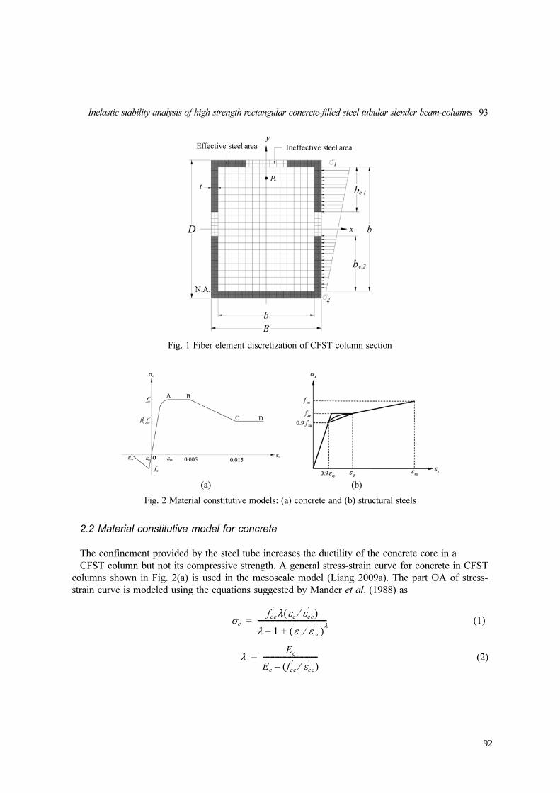
Inelastic stability analysis of high strength rectangular concrete-filled steel tubular slender beam-columns 93
2.2 Material constitutive model for concrete
The confinement provided by the steel tube increases the ductility of the concrete core in a
CFST column but not its compressive strength. A general stress-strain curve for concrete in CFST
columns shown in Fig. 2(a) is used in the mesoscale model (Liang 2009a). The part OA of stress-
strain curve is modeled using the equations suggested by Mander et al. (1988) as
(1)
(2)
σc
fcc
′
λ εcεcc
′
⁄( )
λ 1 εcεcc
′
⁄( )λ
+–
----------------------------------------=
λ
Ec
Ec
fcc
′
εcc
′
⁄( )–
--------------------------------=
Fig. 1 Fiber element discretization of CFST column section
Fig. 2 Material constitutive models: (a) concrete and (b) structural steels
92

94 Vipulkumar Ishavarbhai Patel, Qing Quan Liang and Muhammad N.S. Hadi
(MPa) (3)
where is the compressive concrete stress, is the effective compressive strength of concrete,
is the compressive concrete strain and is the strain at and is the Young’s modulus of
concrete. The strain is between 0.002 and 0.003 depending on the effective compressive
strength of concrete (Liang 2009a). The effective compressive strength of concrete ( ) is taken as
, where is the strength reduction factor proposed by Liang (2009a) to account for the
column size effect and is expressed by
(4)
where is taken as the larger of and (D − 2t) for a rectangular cross-section, B is the
width of the cross-section, D is the depth of the cross-section and t is the thickness of the steel tube
wall as shown in Fig. 2(a).
The model for parts AB, BC and CD of the stress-strain curve for concrete as shown in Fig. 2(a)
was given by Liang (2009a) as
(5)
where was proposed by Liang (2009a) based on experimental results presented by Tomii and
Sakino (1979) and is given by
(6)
where is taken as the larger of B and D for a rectangular cross-section.
The stress-strain curve for concrete in tension is shown in Fig. 2(a). The concrete tensile strength
is taken as and ultimate strain is taken as 10 times of the strain at cracking.
2.3 Material constitutive model for structural steels
Steel tubes are usually made of high strength structural steel, cold-formed steel or mild structural
steel. For mild structural steels, an idealized tri-linear stress-strain curve is assumed as shown in
Fig. 2(b), where fsy and fsu are the yield stress and tensile strength of the steel respectively. An
idealized linear-rounded-linear stress-strain curve is used for cold-formed steels. The rounded part in
the curve can be modeled by a formula proposed by Liang (2009a). For high strength steels, the
rounded part is replaced by a straight line.
Ec
3320 fcc
′
6900+=
σc
fcc
′
εc
εcc
′
fcc
′
Ec
εcc
′
fcc
′
γc fc
′
γc
γc
1.85Dc
0.135–
= 0.85 γc
1.0<≤( )
Dc
B 2t–( )
σc
fcc
′
for εcc
′
εc
0.005< <
βc fcc
′
100 0.015 εc
–( ) fcc
′
βc fcc
′
–( )+ for 0.005 εc
0.015≤<
βc fcc
′
for εc
0.015>⎩
⎪
⎪
⎨
⎪
⎪
⎧
=
βc
βc
1.0 for Bs
t 24≤⁄
1.5 Bs
48t⁄– for 24 Bs
t 48≤⁄<
0.5 for Bs
t⁄ 48>⎩
⎪
⎨
⎪
⎧
=
Bs
0.6 fcc
′
93

Inelastic stability analysis of high strength rectangular concrete-filled steel tubular slender beam-columns 95
2.4 Local and post-local buckling
The effects of local and post-local buckling of high strength CFST beam-columns are taken into
account in the mesoscale model. For a CFST column under axial load and bending, the steel tube
walls may be subjected to compressive stress gradients as depicted in Fig. 1. The classical elastic
local buckling theory cannot be used to determine the initial local buckling stress of thin steel plates
with initial geometric imperfections (Liang et al. 2007). The formulas proposed by Liang et al.
(2007) are therefore incorporated in the mesoscale model to determine the initial local buckling
stresses of steel tube walls under stress gradients.
The effective width concept is usually used to determine the post-local buckling strength of thin
steel plates under uniform compression or stress gradients as shown in Fig. 1. The effective widths
and shown in Fig. 1 are given by Liang et al. (2007)
(7)
(8)
where b is the clear width of a steel web or flange of the box section, and , where
and are the maximum and minimum edge stresses acting on the steel tube wall.
In the mesoscale model, the progressive post-local buckling is modeled by gradually redistributing
the normal stresses within the steel tube wall under increasing compression load based on the stress
levels (Liang 2009a). After initial local buckling, steel fiber stresses are updated to account for post-
local buckling effects.
2.5 Stress resultants
Axial force and moments carried by a CFST column section are determined as stress resultants by
integration as follows
(9)
(10)
(11)
where P is the axial force, is the stress of steel fiber i, is the area of steel fiber i, is
the stress of concrete fiber j, is the area of concrete fiber j, and are the coordinates of
be1
be2
be1
b
-------0.2777 0.01019 b t⁄( ) 1.972 10
4–
b t⁄( )2
× 9.605 107–
b t⁄( )3
×+–+ for αs
0.0>
0.4186 0.002047– b t⁄( ) 5.355 105–
b t⁄( )2
× 4.685 107–
b t⁄( )3
×–+ for αs
0.0=
⎩
⎪
⎨
⎪
⎧
=
be2
b
------- 2 αs
–( )be1
b
-------=
αs
σ2σ
1⁄= σ
1
σ2
P σs i,
As i,
i 1=
ns
∑σ
c j, A
c j,
j 1=
nc
∑+=
Mx
σs i,
As i,
yi
i 1=
ns
∑σ
c j, A
c j,
j 1=
nc
∑ y
j+=
My
σs i,
As i,
xi
i 1=
ns
∑σ
c j, A
c j,
j 1=
nc
∑ x
j+=
σs i,
As i,
σc j,
Ac j,
xi
yi
94

96 Vipulkumar Ishavarbhai Patel, Qing Quan Liang and Muhammad N.S. Hadi
steel element i, and are the coordinates of concrete element j, ns is the total number of steel
fiber elements and nc is the total number of concrete fiber elements.
3. Macroscale simulation
3.1 Macroscale model
The macroscale model for a pin-ended beam-column under axial load at an eccentricity e is
shown in Fig. 3. The deflected shape of the beam-column is assumed to be part of sine wave and is
expressed by
(12)
where L is the effective length of the beam-column and is the deflection at the mid-height.
The curvature at the mid-height of the beam-column can be obtained as
(13)
The external moment at the mid-height of the beam-column with an initial geometric imperfection
at the mid-height can be calculated by
(14)
To compute the load-deflection curve for a CFST slender beam-column under eccentric loading,
the deflection at the column mid-height ( ) is gradually increased. The curvature at the
xj
yj
u um
πz
L
-----⎝ ⎠
⎛ ⎞sin=
um
φm
π
L
---⎝ ⎠
⎛ ⎞2
um
=
uo
Mme
P e um
uo
+ +( )=
um
φm
Fig. 3 Pin-ended beam-column model
95

Inelastic stability analysis of high strength rectangular concrete-filled steel tubular slender beam-columns 97
column mid-height is computed from the deflection . The neutral axis depth is then adjusted to
achieve the moment equilibrium at the mid-height of the beam-column. The following equilibrium
equation must be satisfied
(15)
where is the internal moment carried by the section.
3.2 Numerical solution method
Iterative numerical algorithms based on the Müller’s method (Müller 1956) are developed to
obtain nonlinear solutions (Patel et al. 2012a, b). The Müller’s method requires three starting values
of the neutral axis depth , and . The corresponding residual moments , and
are calculated from these initial values. The new neutral axis depth that approaches the
true value is determined by the following equations
(16)
(17)
(18)
(19)
where is the residual moment at the mid-height of the column, which is given by
(20)
To obtain converged solutions, the values of , and and residual moments ,
and need to be exchanged and Eq. (16) is used to adjust the (Patel et al. 2012a).
3.3 Computational procedure
Computational algorithms have been developed to implement the macroscale model for thin-
walled CFST slender beam-columns incorporating the mesoscale model. The main steps of the
computational procedure are given as follows:
(1) Discretize composite section into fine fiber elements.
(2) Initialize the mid-height deflection: .
(3) Compute the curvature at the mid-height of the slender beam-column.
(4) Initialize , and .
(5) Calculate fiber stresses using material models.
(6) Check local buckling and redistribute steel fiber stresses accordingly.
(7) Compute internal moment and external moment .
(8) Calculate residual moments , and corresponding to , and .
(9) Adjust the neutral axis depth using the Müller’s method.
um
P e um
uo
+ +( ) Mmi
– 0=
Mmi
dn 1,
dn 2,
dn 3,
rpu 1,
rpu 2,
rpu 3,
dn 4,
dn 4,
dn 3,
2cm
–
bm
bm
2
4am
cm
–±
-----------------------------------------+=
am
dn 2,
dn 3,
–( ) rpu 1,
rpu 3,
–( ) dn 1,
dn 3,
–( ) rpu 2,
rpu 3,
–( )–
dn 1,
dn 2,
–( ) dn 1,
dn 3,
–( ) dn 2,
dn 3,
–( )
-------------------------------------------------------------------------------------------------------------------------------=
bm
dn 1,
dn 3,
–( )2
rpu 2,
rpu 3,
–( ) dn 2,
dn 3,
–( )2
rpu 1,
rpu 3,
–( )–
dn 1,
dn 2,
–( ) dn 1,
dn 3,
–( ) dn 2,
dn 3,
–( )
------------------------------------------------------------------------------------------------------------------------------------=
cm
rpu 3,
=
rpu
rpu
P e um
uo
+ +( ) Mmi
–=
dn 1,
dn 2,
dn 3,
rpu 1,
rpu 2,
rpu 3,
dn
um
Δum
=
φm
dn 1,
D 4⁄= dn 2,
D 2⁄= dn 3,
D=
Mmi
Mme
rpu 1,
rpu 2,
rpu 3,
dn 1,
dn 2,
dn 3,
dn
96

98 Vipulkumar Ishavarbhai Patel, Qing Quan Liang and Muhammad N.S. Hadi
(10) Calculate fiber stresses using material models.
(11) Check local buckling and redistribute steel fiber stresses accordingly.
(12) Compute internal moment and external moment .
(13) Repeat Steps (9)-(12) until .
(14) Increase the mid-height deflection of the beam-column by .
(15) Repeat Steps (3)-(14) until the ultimate load is obtained or the deflection limit is reached.
(16) Plot the axial load-deflection curve.
4. Performance indices
Performance indices that evaluate the contributions of steel and concrete components to the
ultimate strengths of CFST slender beam-columns can be used to study economical composite
designs. The steel contribution ratio is used to quantify the contribution of the hollow steel tubular
column to the ultimate strength of the CFST slender beam-column and is defined as
(21)
where is the ultimate axial strength of the calculated hollow steel slender beam-column and
is the ultimate axial strength of the CFST slender beam-column. The ultimate axial strength
is calculated by setting the concrete compressive strength to zero in the numerical analysis
while other conditions remain the same as the CFST beam-column.
The concrete contribution ratio is used to determine the contribution of the concrete core to
ultimate strength of the CFST slender beam-column, which is defined as
(22)
The strength reduction factor is used to measure the performance of a CFST slender beam-column
over its section and is defined as
(23)
where is the ultimate axial strength of the beam-column section under axial compression.
5. Verification
The ultimate axial strengths of uniaxially loaded CFST slender beam-columns predicted by
the numerical model are compared with experimental results in Table 1, where Es is the Young's
modulus. Specimens SCH-1, SCH-2 and SCH-7 were tested by Bridge (1976) while test results of
specimens E03, E04, E07, E08, E11, E12, L1, L2, L3 and L4 were provided by Liu (2004, 2006)
and specimens M1, M4, M6, M7 and M8 were tested by Zhang et al. (2003). In Table 1, the
concrete cylinder compressive strength was taken as 0.85 times the concrete cube compressive
strength . It can be observed from Table 1 that the predicted ultimate axial strengths are in
good agreement with corresponding test results. The mean value of the predicted axial strength
Mmi
Mme
rpu
104–
<
um
um
Δum
+=
Pu
ξs
Pu .steel
Pu
---------------=
Pu .steel
Pu
Pu .steel
ξc
Pu
Pu .steel
–
Pu
---------------------------=
αc
Pu
Po
-----=
Po
fc
′
( )
fcu
( )
97

Inelastic stability analysis of high strength rectangular concrete-filled steel tubular slender beam-columns 99
to the experimental value is 0.96 with a standard deviation of 0.06 and the
coefficient of variation of 0.06. Fig. 4 shows the predicted and experimental load-deflection curves
for specimens L3 and L4. It can be seen from the figure that the numerical model predicts well the
load-deflection responses of the specimens. It can be concluded that the numerical model yields
good predications of the nonlinear inelastic behavior of normal and high strength CFST slender
beam-columns.
6. Applications
The numerical model developed was used to investigate the effects of concrete compressive
strength, loading eccentricity ratio , depth-to-thickness ratio and column slenderness
ratio on the performance indices. The following parameters are kept constant in the present
parametric study. The initial geometric imperfection at the mid-height of the beam-column was
taken as . The yield and tensile strengths of the steel tubes were 690 and 790 MPa
respectively. The Young’s modulus of steel was 200 GPa.
Pu .num
( ) Pu . exp
( )
e D⁄( ) D t⁄( )
L r⁄( )
L 1500⁄
Table 1 Comparison of predicted and experimental ultimate axial strengths of CFST columns
Speci-
mensB × D × t (mm) D / t
L
(mm)
e
(mm)
uo
(mm) (MPa)
fsy
(MPa)
fsu
(MPa)
Es
(GPa)
Pu.exp
(KN)
Pu.num
(KN)
SCH-1 203.7 × 203.9 × 9.96 20 2130 38 1.19 29.9 291 410 205 1956 1995.73 1.02
SCH-2 204.0 × 203.3 × 10.01 20 3050 50 1.4 31.1 290 410 205 2869 2907.4 1.01
SCH-7 152.5 × 152.3 × 6.48 24 3050 38 0.51 31.1 254 410 205 680 734.0 1.08
E03 150 × 150 × 4.18 36 2170 30 60 550 608 207 1330 1252.42 0.93
E04 150 × 150 × 4.18 36 2170 60 70 550 608 207 1020 972.74 0.95
E07 80 × 120 × 4.18 29 1740 20 60 550 608 207 660 740.56 1.12
E08 80 × 120 × 4.18 29 1740 20 70 550 608 207 855 776.14 0.91
E11 80 × 160 × 4.18 38 2310 60 60 550 608 207 670 640.76 0.96
E12 80 × 160 × 4.18 38 2310 30 70 550 608 207 1020 909.89 0.89
L1 100 × 150 × 4 38 2600 15 60 495 581 206 1130 1013.86 0.90
L2 100 × 150 × 4 38 2600 30 60 495 581 206 884 804.82 0.91
L3 100 × 150 × 4 38 2600 45 60 495 581 206 711 674.74 0.95
L4 100 × 150 × 4 38 2600 60 60 495 581 206 617 587.37 0.95
M1 149.44 × 149.44 × 2.89 52 1090 43 80 319.3 430 200 1147 1038.11 0.91
M4 148.31 × 148.31 × 2.87 52 3101 26 80 319.3 430 200 931 844.70 0.91
M6 152.12 × 152.12 × 4.82 32 1105 41.5 80 316.6 430 200 1416 1331.35 0.94
M7 150.82 × 150.82 × 4.86 31 2199 21 80 316.6 430 200 1519 1412.68 0.93
M8 150.37 × 150.37 × 4.86 31 3100 25.5 80 316.6 430 200 1103 1094.06 0.99
Mean 0.96
Standard deviation (SD) 0.06
Coefficient of variation(COV) 0.06
fc
′
Pu .num
Pu.exp
-------------
98

100 Vipulkumar Ishavarbhai Patel, Qing Quan Liang and Muhammad N.S. Hadi
6.1 Steel contribution ratio
A column cross-section of 600 × 700 mm was considered in the study of steel contribution ratio.
The depth-to-thickness ratio of 70, the column slenderness ratio of 60 and the loading eccentricity
Fig. 4 Comparison of predicted and experimental axial load-deflection curves
Fig. 5 Steel contribution ratio
99
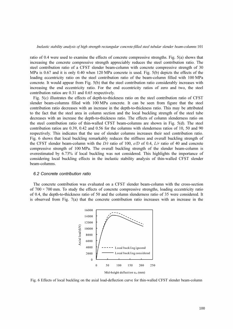
Inelastic stability analysis of high strength rectangular concrete-filled steel tubular slender beam-columns 101
ratio of 0.4 were used to examine the effects of concrete compressive strengths. Fig. 5(a) shows that
increasing the concrete compressive strength appreciably reduces the steel contribution ratio. The
steel contribution ratio of a CFST slender beam-column with concrete compressive strength of 30
MPa is 0.67 and it is only 0.40 when 120 MPa concrete is used. Fig. 5(b) depicts the effects of the
loading eccentricity ratio on the steel contribution ratio of the beam-column filled with 100 MPa
concrete. It would appear from Fig. 5(b) that the steel contribution ratio considerably increases with
increasing the end eccentricity ratio. For the end eccentricity ratios of zero and two, the steel
contribution ratios are 0.31 and 0.65 respectively.
Fig. 5(c) illustrates the effects of depth-to-thickness ratio on the steel contribution ratio of CFST
slender beam-columns filled with 100 MPa concrete. It can be seen from figure that the steel
contribution ratio decreases with an increase in the depth-to-thickness ratio. This may be attributed
to the fact that the steel area in column section and the local buckling strength of the steel tube
decreases with an increase the depth-to-thickness ratio. The effects of column slenderness ratio on
the steel contribution ratio of thin-walled CFST beam-columns are shown in Fig. 5(d). The steel
contribution ratios are 0.39, 0.42 and 0.56 for the columns with slenderness ratios of 10, 50 and 90
respectively. This indicates that the use of slender columns increases their seel contribution ratio.
Fig. 6 shows that local buckling remarkably reduces the stiffness and overall buckling strength of
the CFST slender beam-column with the D/t ratio of 100, e/D of 0.4, L/r ratio of 40 and concrete
compressive strength of 100 MPa. The overall buckling strength of the slender beam-column is
overestimated by 6.73% if local buckling was not considered. This highlights the importance of
considering local buckling effects in the inelastic stability analysis of thin-walled CFST slender
beam-columns.
6.2 Concrete contribution ratio
The concrete contribution was evaluated on a CFST slender beam-column with the cross-section
of 700 × 700 mm. To study the effects of concrete compressive strengths, loading eccentricity ratio
of 0.4, the depth-to-thickness ratio of 50 and the column slenderness ratio of 35 were considered. It
is observed from Fig. 7(a) that the concrete contribution ratio increases with an increase in the
Fig. 6 Effects of local buckling on the axial load-deflection curve for thin-walled CFST slender beam-column
100

102 Vipulkumar Ishavarbhai Patel, Qing Quan Liang and Muhammad N.S. Hadi
concrete compressive strength. Fig. 7(b) shows the effects of the loading eccentricity ratio on the
concrete contribution ratio of the beam-column filled with 90 MPa concrete. It appears that
increasing the loading eccentricity ratio significantly reduces the concrete contribution ratio of
CFST slender beam-columns.
The effects of depth-to-thickness ratio and column slenderness ratio on the concrete contribution
ratio of the beam-columns filled with 90 MPa concrete are shown in Fig. 7(c) and Fig. 7(d)
respectively. It can be seen from Fig. 7(c) that increasing the depth-to-thickness ratio significantly
increases the concrete contribution ratio. Fig. 7(d) shows that increasing the column slenderness
ratio decreases the concrete contribution ratio.
6.3 Strength reduction factor
The cross-section of a CFST slender beam-column used in the analysis was 500 × 600 mm. The
depth-to-thickness ratio of 60, loading eccentricity ratio of 0.4 and the slenderness ratio of 60 were
used to study the effects of concrete compressive strengths. Fig. 8(a) indicates that increasing the
concrete compressive strength significantly reduces the strength reduction factor. The effects of
loading eccentricity ratio on the strength reduction factor of the beam-columns filled with 80 MPa
concrete are presented in Fig. 8(b). It appears from Fig. 8(b) that the strength reduction factor
Fig. 7 Concrete contribution ratio
101
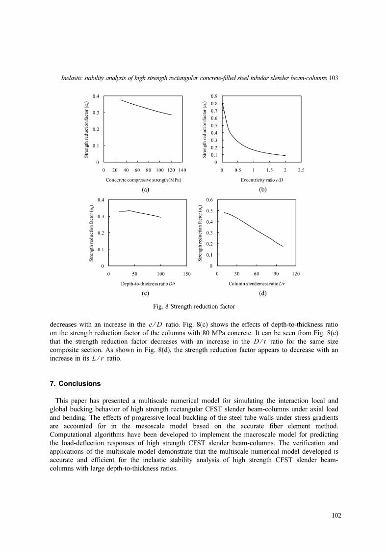
Inelastic stability analysis of high strength rectangular concrete-filled steel tubular slender beam-columns 103
decreases with an increase in the ratio. Fig. 8(c) shows the effects of depth-to-thickness ratio
on the strength reduction factor of the columns with 80 MPa concrete. It can be seen from Fig. 8(c)
that the strength reduction factor decreases with an increase in the ratio for the same size
composite section. As shown in Fig. 8(d), the strength reduction factor appears to decrease with an
increase in its ratio.
7. Conclusions
This paper has presented a multiscale numerical model for simulating the interaction local and
global bucking behavior of high strength rectangular CFST slender beam-columns under axial load
and bending. The effects of progressive local buckling of the steel tube walls under stress gradients
are accounted for in the mesoscale model based on the accurate fiber element method.
Computational algorithms have been developed to implement the macroscale model for predicting
the load-deflection responses of high strength CFST slender beam-columns. The verification and
applications of the multiscale model demonstrate that the multiscale numerical model developed is
accurate and efficient for the inelastic stability analysis of high strength CFST slender beam-
columns with large depth-to-thickness ratios.
e D⁄
D t⁄
L r⁄
Fig. 8 Strength reduction factor
102

104 Vipulkumar Ishavarbhai Patel, Qing Quan Liang and Muhammad N.S. Hadi
References
Bridge, R.Q. (1976), “Concrete filled steel tubular columns”, School of Civil Engineering, The University of
Sydney, Sydney, Australia, Research Report No. R 283.
Ellobody, E., Young, B. and Lam, D. (2006), “Behaviour of normal and high strength concrete-filled compact
steel tube circular stub columns”, J. Constr. Steel Res., 62(7), 706-715.
Han, L.H. (2002), “Tests on stub columns of concrete-filled RHS sections”, J. Constr. Steel Res., 58(3), 353-372.
Hu, H.T., Huang, C.S., Wu, M.H. and Wu, Y.M. (2003), “Nonlinear analysis of axially loaded concrete-filled
tube columns with confinement effect”, J. Struct. Eng.-ASCE, 129(10), 1322-1329.
Lakshmi, B. and Shanmugam, N.E. (2002), “Nonlinear analysis of in-filled steel-concrete composite columns”, J.
Struct. Eng.-ASCE, 128(7), 922-933.
Laskar, A., Zhong, J., Mo, Y.L. and Hsu, T.T.C. (2009), “Multiscale modeling of reinforced/prestressed concrete
thin-walled structures”, Interact. Multiscale Mech., 2(1), 69-89.
Liang, Q.Q. (2009a), “Performance-based analysis of concrete-filled steel tubular beam-columns, Part I: Theory
and algorithms”, J. Constr. Steel Res., 65(2), 363-372.
Liang, Q.Q. (2009b), “Performance-based analysis of concrete-filled steel tubular beam-columns, Part II:
Verification and applications”, J. Constr. Steel Res., 65(2), 351-362.
Liang, Q.Q. (2011a), “High strength circular concrete-filled steel tubular slender beam-columns, Part I:
Numerical analysis”, J. Constr. Steel Res., 67(2), 164-171.
Liang, Q.Q. (2011b), “High strength circular concrete-filled steel tubular slender beam-columns, Part II:
Fundamental behavior”, J. Constr. Steel Res., 67(2), 172-180.
Liang, Q.Q., Uy, B. and Liew, J.Y.R. (2007), “Local buckling of steel plates in concrete-filled steel tubular beam-
columns”, J. Constr. Steel Res., 63(3), 396-405.
Liu, D. (2004), “Behaviour of high strength rectangular concrete-filled steel hollow section columns under
eccentric loading”, Thin Wall. Struct., 42(12), 1631-1644.
Liu, D. (2006), “Behaviour of eccentrically loaded high-strength rectangular concrete-filled steel tubular
columns”, J. Constr. Steel Res., 62(8), 839-846.
Mander, J.B., Priestly, M.N.J. and Park, R. (1988), “Theoretical stress-strain model for confined concrete”, J.
Struct. Eng.-ASCE, 114(8), 1804-1826.
Müller, D.E. (1956), “A method for solving algebraic equations using an automatic computer”, MTAC, 10(56),
208-215.
Nagarajan, P., Jayadeep, U.B. and Pillai, T.M.M. (2010), “Mesoscopic numerical analysis of reinforced concrete
beams using a modified micro truss model”, Interact. Multiscale Mech., 3(1), 23-37.
Patel, V.I., Liang, Q.Q. and Hadi, M.N.S. (2012a), “High strength thin-walled rectangular concrete-filled steel
tubular slender beam-columns, Part I: Modeling”, J. Constr. Steel Res., 70, 377-384.
Patel, V.I., Liang, Q.Q. and Hadi, M.N.S. (2012b), “High strength thin-walled rectangular concrete-filled steel
tubular slender beam-columns, Part II: Behavior”, J. Constr. Steel Res., 70, 368-376.
Sakino, K., Nakahara, H., Morino, S. and Nishiyama, I. (2004), “Behavior of centrally loaded concrete-filled
steel-tube short columns”, J. Struct. Eng.-ASCE, 130(2), 180-188.
Schneider, S.P. (1998), “Axially loaded concrete-filled steel tubes”, J. Struct. Eng.-ASCE, 124(10), 1125-1138.
Shakir-Khalil, H. and Zeghiche, J. (1989), “Experimental behaviour of concrete-filled rolled rectangular hollow-
section columns”, Struct. Eng., 67(19), 346-353.
Tomii, M. and Sakino, K. (1979), “Elastic-plastic behaviour of concrete filled square steel tubular beam-
columns”, Trans. Arch. Inst, 280, 111-120.
Zhang, S., Guo, L. and Tian, H. (2003), “Eccentrically loaded high strength concrete-filled square steel tubes”,
Adv. Struct., Proc. of the Int. Conf. on Advances in Structures, Sydney, Australia.
103

Chapter 3: Rectangular CFST Slender Beam-columns under Axial Load and Uniaxial Bending
V. I. Patel: Nonlinear Inelastic Analysis of Concrete-Filled Steel Tubular Slender Beam-Columns 104
3.6 CONCLUDING REMARKS
This chapter has presented a numerical model for thin-walled high strength rectangular
CFST slender beam-columns under axial load and uniaxial bending. The effects of local
buckling of steel tube walls under stress gradients, initial geometric imperfection and
second order were considered in the numerical model. Performance indices have been
proposed for evaluating the performance of thin-walled CFST slender beam-columns.
Efficient Müller’s method algorithms were developed and implemented in the computer
program. These algorithms were used to iterate the neutral axis depth in the composite
cross-section and to adjust the curvature at the column ends in the slender beam-column
to satisfy equilibrium conditions. The analysis procedures have been presented.
It has been shown that the proposed numerical model can accurately predict the
structural performance of CFST slender beam-columns. The numerical model
developed was employed to investigate the effects of local buckling, depth-to-thickness
ratios, loading eccentricity ratios, column slenderness ratios, concrete compressive
strengths and steel yield strengths on the axial load-deflection curves and axial load-
moment interaction diagrams for CFST beam-columns. Parametric studies indicated
that increasing depth-to-thickness ratios reduces the ultimate axial strength of thin-
walled CFST beam-columns but enlarges the normalized axial load-moment interaction
diagrams. Increasing the concrete compressive strengths increases the ultimate axial
strength of thin-walled CFST beam-columns and enlarges the normalized axial load-
moment interaction diagrams but reduces steel contribution ratio and strength reduction
factor.

Chapter 4: Rectangular CFST Slender Beam-columns under Axial Load and Biaxial Bending
V. I. Patel: Nonlinear Inelastic Analysis of Concrete-Filled Steel Tubular Slender Beam-Columns 105
Chapter 4
RECTANGULAR CFST SLENDER BEAM-
COLUMNS UNDER AXIAL LOAD AND BIAXIAL
BENDING
4.1 INTRODUCTION
This chapter presents a multiscale numerical model for simulating the structural
behavior of high strength thin-walled rectangular CFST slender beam-columns under
axial load and biaxial bending. The numerical model incorporates progressive local
buckling, initial geometric imperfections, high strength materials and second order
effects. The numerical model is validated against the test results available in the
published literature. Steel and concrete contribution ratios and strength reduction factor
are used to evaluate the performance of CFST slender beam-columns. Parametric
studies using the numerical model are performed to investigate the effects of depth-to-
Chapter 4: Rectangular CFST Slender Beam-columns under Axial Load and Biaxial Bending
V. I. Patel: Nonlinear Inelastic Analysis of Concrete-Filled Steel Tubular Slender Beam-Columns 106
thickness ratios, loading eccentricity ratios, column slenderness ratios, concrete
compressive strengths and steel yield strengths on the performance of thin-walled CFST
slender beam-columns.
This chapter includes the following papers:
[1] Liang, Q. Q., Patel, V. I. and Hadi, M. N. S., “Biaxially loaded high-strength
concrete-filled steel tubular slender beam-columns, Part I: Multiscale simulation”,
Journal of Constructional Steel Research, 2012, 75, 64-71.
[2] Patel, V. I., Liang, Q. Q. and Hadi, M. N. S., “Biaxially loaded high-strength
concrete-filled steel tubular slender beam-columns, Part II: Parametric study”,
Journal of Constructional Steel Research, 2011 (submitted).

107

108

109

110

Journal of Constructional Steel Research 75 (2012) 64–71
Contents lists available at SciVerse ScienceDirect
Journal of Constructional Steel Research
Biaxially loaded high-strength concrete-filled steel tubular slender beam-columns,Part I: Multiscale simulation
Qing Quan Liang a,⁎, Vipulkumar Ishvarbhai Patel a, Muhammad N.S. Hadi b
a School of Engineering and Science, Victoria University, PO Box 14428, Melbourne, VIC 8001, Australiab School of Civil, Mining and Environmental Engineering, University of Wollongong, Wollongong, NSW 2522, Australia
⁎ Corresponding author. Tel.: +61 3 9919 4134; fax:E-mail address: [email protected] (Q.Q. Liang).
0143-974X/$ – see front matter © 2012 Elsevier Ltd. Aldoi:10.1016/j.jcsr.2012.03.005
a b s t r a c t
a r t i c l e i n f oArticle history:Received 13 October 2011Accepted 12 March 2012Available online 6 April 2012
Keywords:Biaxial bendingConcrete-filled steel tubesHigh strength materialsLocal and post-local bucklingNonlinear analysisSlender beam-columns
The steel tube walls of a biaxially loaded thin-walled rectangular concrete-filled steel tubular (CFST) slenderbeam-column may be subjected to compressive stress gradients. Local buckling of the steel tube walls understress gradients, which significantly reduces the stiffness and strength of a CFST beam-column, needs to beconsidered in the inelastic analysis of the slender beam-column. Existing numerical models that do notconsider local buckling effects may overestimate the ultimate strengths of thin-walled CFST slender beam-columns under biaxial loads. This paper presents a newmultiscale numerical model for simulating the structuralperformance of biaxially loaded high-strength rectangular CFST slender beam-columns accounting for progressivelocal buckling, initial geometric imperfections, high strength materials and second order effects. The inelasticbehavior of column cross-sections is modeled at the mesoscale level using the accurate fiber element method.Macroscale models are developed to simulate the load-deflection responses and strength envelopes of thin-walled CFST slender beam-columns. New computational algorithms based on the Müller's method are developedto iteratively adjust the depth and orientation of the neutral axis and the curvature at the column's ends to obtainnonlinear solutions. Steel and concrete contribution ratios and strength reduction factor are proposed for evaluat-ing the performance of CFST slender beam-columns. Computational algorithms developed are shown to be anaccurate and efficient computer simulation and design tool for biaxially loaded high-strength thin-walled CFSTslender beam-columns. The verification of the multiscale numerical model and parametric study are presentedin a companion paper.
© 2012 Elsevier Ltd. All rights reserved.
1. Introduction
High strength thin-walled rectangular concrete-filled steel tubular(CFST) slender beam-columns in composite frames may be subjectedto axial load and biaxial bending. Biaxially loaded thin-walled CFSTslender beam-columnswith large depth-to-thickness ratios are vulner-able to local and global buckling. No numericalmodels have been devel-oped for the multiscale inelastic stability analysis of biaxially loadedhigh strength thin-walled CFST slender beam-columns accounting forthe effects of progressive local buckling of the steel tube walls understress gradients. The difficulty is caused by the interaction betweenlocal and global buckling and biaxial bending. However, it is importantto accurately predict the ultimate strength of a thin-walled CFST slenderbeam-column under biaxial loads because this strength is needed in thepractical design. This paper addresses the important issue of multiscalesimulation of high strength thin-walled rectangular CFST slender beam-columns under combined axial load and biaxial bending.
+61 3 9919 4139.
l rights reserved.
Extensive experimental investigations have been undertaken to de-termine the ultimate strengths of short and slender CFST columnsunder axial load or combined axial load and uniaxial bending [1–9].Test results indicated that the confinement provided by the rectangularsteel tube had little effect on the compressive strength of the concretecore but considerably improved its ductility. In addition, local bucklingof the steel tubes was found to remarkably reduce the ultimate strengthand stiffness of thin-walled CFST short columns as reported by Ge andUsami [10], Bridge and O'Shea [11], Uy [12] and Han [13]. As a result,the ultimate strengths of rectangular CFST short columns can be deter-mined by summation of the capacities of the steel tube and concretecore, providing that local buckling effects are taken into account asshown by Liang et al. [14]. Moreover, experimental results demonstratedthat the confinement effect significantly increased the compressivestrength and ductility of the concrete core in circular CFST short columns.However, this confinement effect was found to reduce with increasingthe column slenderness as illustrated by Knowles and Park [2] andLiang [15]. In comparisons with researches on CFST columns underaxial load and uniaxial bending, experimental investigations on biaxiallyloaded rectangular thin-walled CFST slender beam-columns have re-ceived little attention [16–18].
111
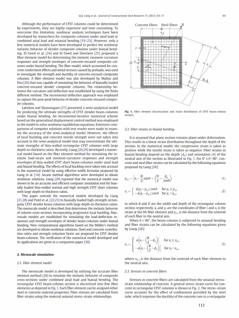
Concrete fibers
D
B
N.A.
Pn
x
y
dn
de,i
ε t
εi
yi
yn,i
Steel fibers
θ
α
θ
t
Fig. 1. Fiber element discretization and strain distribution of CFST beam-columnsection.
65Q.Q. Liang et al. / Journal of Constructional Steel Research 75 (2012) 64–71
Although the performance of CFST columns could be determinedby experiments, they are highly expensive and time consuming. Toovercome this limitation, nonlinear analysis techniques have beendeveloped by researchers for composite columns under axial load orcombined axial load and uniaxial bending [19–23]. However, only afew numerical models have been developed to predict the nonlinearinelastic behavior of slender composite columns under biaxial bend-ing. El-Tawil et al. [24] and El-Tawil and Deierlein [25] proposed afiber element model for determining the inelastic moment-curvatureresponses and strength envelopes of concrete-encased composite col-umns under biaxial bending. The fiber model, which accounted for con-crete conferment effects and initial stresses caused by preloads, was usedto investigate the strength and ductility of concrete-encased compositecolumns. A fiber element model was also developed by Muñoz andHsu [26] that was capable of simulating the behavior of biaxially loadedconcrete-encased slender composite columns. The relationship be-tween the curvature and deflection was established by using the finitedifferent method. The incremental deflection approach was employedto capture the post-peak behavior of slender concrete-encased compos-ite columns.
Lakshmi and Shanmugam [27] presented a semi-analytical modelfor predicting the ultimate strengths of CFST slender beam-columnsunder biaxial bending. An incremental-iterative numerical schemebased on the generalized displacement control methodwas employedin themodel to solve nonlinear equilibrium equations. Extensive com-parisons of computer solutions with test results were made to exam-ine the accuracy of the semi-analytical model. However, the effectsof local buckling and concrete tensile strength were not taken intoaccount in the semi-analytical model that may overestimate the ulti-mate strengths of thin-walled rectangular CFST columns with largedepth-to-thickness ratios. Recently, Liang [28,29] developed a numer-ical model based on the fiber element method for simulating the in-elastic load-strain and moment-curvature responses and strengthenvelopes of thin-walled CFST short beam-columns under axial loadand biaxial bending. The effects of local bucklingwere taken into accountin the numerical model by using effective width formulas proposed byLiang et al. [14]. Secant method algorithms were developed to obtainnonlinear solutions. Liang [29] reported that the numerical model wasshown to be an accurate and efficient computer simulation tool for biax-ially loaded thin-walled normal and high strength CFST short columnswith large depth-to-thickness ratios.
This paper extends the numerical models developed by Liang[21,28] and Patel et al. [22,23] to biaxially loaded high-strength rectan-gular CFST slender beam-columns with large depth-to-thickness ratios.The mesoscale model is described that determines the inelastic behaviorof column cross-sections incorporating progressive local buckling. Mac-roscale models are established for simulating the load-deflection re-sponses and strength envelopes of slender beam-columns under biaxialbending. New computational algorithms based on the Müller's methodare developed to obtain nonlinear solutions. Steel and concrete contribu-tion ratios and strength reduction factor are proposed for CFST slenderbeam-columns. The verification of the numerical model developed andits applications are given in a companion paper [30].
2. Mesoscale simulation
2.1. Fiber element model
The mesoscale model is developed by utilizing the accurate fiberelement method [28] to simulate the inelastic behavior of compositecross-sections under combined axial load and biaxial bending. Therectangular CFST beam-column section is discretized into fine fiberelements as depicted in Fig. 1. Each fiber element can be assigned eithersteel or concrete material properties. Fiber stresses are calculated fromfiber strains using the material uniaxial stress–strain relationships.
2.2. Fiber strains in biaxial bending
It is assumed that plane section remains plane under deformation.This results in a linear strain distribution throughout the depth of thesection. In the numerical model, the compressive strain is taken aspositive while the tensile strain is taken as negative. Fiber strains inbiaxial bending depend on the depth (dn) and orientation (θ) of theneutral axis of the section as illustrated in Fig. 1. For 0°≤θb90°, con-crete and steel fiber strains can be calculated by the following equationsproposed by Laing [28]:
yn;i ¼ xi−B2
�������� tanθþ D
2− dn
cosθ
� �ð1Þ
εi ¼ϕ yi−yn;i�� �� cosθ for yi ≥ yn;i
−ϕ yi−yn;i�� �� cosθ for yi b yn;i
�ð2Þ
in which B and D are the width and depth of the rectangular columnsection respectively, xi and yi are the coordinates of fiber i and εi is thestrain at the ith fiber element and yn, i is the distance from the centroidof each fiber to the neutral axis.
When θ=90°, the beam-column is subjected to uniaxial bendingand fiber strains can be calculated by the following equations givenby Liang [28]:
εi ¼ϕ xi−
B2−dn
� ��������� for xi ≥ xn;i
−ϕ xi−B2−dn
� ��������� for xi b xn;i
8>><>>: ð3Þ
where xn, i is the distance from the centroid of each fiber element tothe neutral axis.
2.3. Stresses in concrete fibers
Stresses in concrete fibers are calculated from the uniaxial stress–strain relationship of concrete. A general stress–strain curve for con-crete in rectangular CFST columns is shown in Fig. 2. The stress–straincurve accounts for the effect of confinement provided by the steeltube, which improves the ductility of the concrete core in a rectangular
112

C D
A B
εc0.0150.005εccεtc
'
fct
ε tu
fcc'
βc f
cc
'
c
o
σ
Fig. 2. Stress–strain curve for confined concrete in rectangular CFST columns.
Fig. 3. Stress–strain curves for structural steels.
66 Q.Q. Liang et al. / Journal of Constructional Steel Research 75 (2012) 64–71
CFST column. The concrete stress from O to A in the stress–strain curveis calculated based on the equations given by Mander et al. [31] as:
σ c ¼f′ccλ
εcε ′cc
� �λ−1þ εc
ε′cc
� �λ ð4Þ
λ ¼ EcEc− f′cc
ε′cc
� � ð5Þ
Ec ¼ 3320ffiffiffiffiffif′cc
qþ 6900 MPað Þ ð6Þ
in which σc stands for the compressive concrete stress, f′cc representsthe effective compressive strength of concrete, εc denotes the compres-sive concrete strain, ε′cc is the strain at f′cc and is between0.002 and 0.003depending on the effective compressive strength of concrete [28]. TheYoung's modulus of concrete Ec was given by ACI [32]. The effectivecompressive strength of concrete f′cc is taken as γcf′c, where γc is thestrength reduction factor proposed by Liang [28] to account for the col-umn size effect and is expressed by
γc ¼ 1:85D−0:135c 0:85≤ γc ≤ 1:0ð Þ ð7Þ
where Dc is taken as the larger of (B−2t) and (D−2t) for a rectangularcross-section, and t is the thickness of the steel tube wall as shown inFig. 1.
The parts AB, BC and CD of the stress–strain curve for concreteshown in Fig. 2 are defined by the following equations proposed byLiang [28]:
σ c ¼f′cc for ε ′cc b εc ≤ 0:005
βcf′cc þ 100 0:015−εcð Þ f′cc−βcf′ccð Þ for 0:005 b εc ≤ 0:015βcf′cc for εc > 0:015
8<: ð8Þ
where βc was proposed by Liang [28] based on experimental resultsprovided by Tomii and Sakino [33] to account for confinement effectson the post-peak behavior and is given by
βc ¼1:0 for
Bs
t≤ 24
1:5− 148
Bs
tfor24 b
Bs
t≤ 48
0:5 forBs
t> 48
8>>>>><>>>>>:
ð9Þ
where Bs is taken as the larger of B and D for a rectangular cross-section.
The stress–strain curve for concrete in tension is shown in Fig. 2.The constitutive model assumes that the concrete tensile stress in-creases linearly with the tensile strain up to concrete cracking. After
concrete cracking, the tensile stress of concrete decreases linearly tozero as the concrete softens. The concrete tensile stress is consideredto be zero at the ultimate tensile strain which is taken as 10 times ofthe strain at concrete cracking. The tensile strength of concrete istaken as 0:6
ffiffiffiffiffif′cc
p.
2.4. Stresses in steel fibers
Stresses in steel fibers are calculated from uniaxial stress–strainrelationship of steel material. Steel tubes used in CFST cross-sectionsare normally made from three types of structural steels such as highstrength structural steels, cold-formed steels and mild structuralsteels, which are considered in the numerical model. Fig. 3 showsthe stress–strain relationship for three types of steels. The steel materialgenerally follows the same stress–strain relationship under the com-pression and tension. The rounded part of the stress–strain curve canbe defined by the equation proposed by Liang [28]. The hardening strainεst is assumed to be 0.005 for high strength and cold-formed steels and10εsy for mild structure steels in the numerical model. The ultimatestrain εsu is taken as 0.2 for steels.
2.5. Initial local buckling
Local buckling significantly reduces the strength and stiffness ofthin-walled CFST beam-columns with large depth-to-thickness ratios.Therefore, it is important to account for local buckling effects in theinelastic analysis of high strength CFST slender beam-columns. How-ever, most of existing numerical models for thin-walled CFST beam-columns have not considered local buckling effects. Thismay be attrib-uted to the complexity of the local instability problem as addressed byLiang et al. [14]. The steel tube walls of a CFST column under axial loadand biaxial bending may be subjected to compressive stress gradientsas depicted in Fig. 4. Due to the presence of initial geometric imperfec-tions, no bifurcation point can be observed on the load-deflectioncurves for real thin steel plates. The classical elastic local buckling the-ory [34] cannot be used to determine the initial local buckling stress ofreal steel plates with imperfections. Liang et al. [14] proposed formulasfor estimating the initial local buckling stresses of thin steel plates understress gradients by considering the effects of geometric imperfectionsand residual stresses. Their formulas are incorporated in the numericalmodel to account for initial local buckling of biaxially loaded CFSTbeam-columns with large depth-to-thickness ratios.
2.6. Post-local buckling
The effective width concept is commonly used to describe thepost-local buckling behavior of a thin steel plate as illustrated in
113
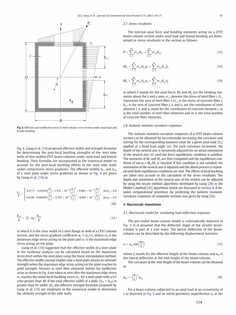
D
N.A.
x
y
b
b
Pn
e,1
e,2
1
2
t
θ
B
Fig. 4. Effective and ineffective areas of steel tubular cross-section under axial load andbiaxial bending.
67Q.Q. Liang et al. / Journal of Constructional Steel Research 75 (2012) 64–71
Fig. 4. Liang et al. [14] proposed effective width and strength formulasfor determining the post-local buckling strengths of the steel tubewalls of thin-walled CFST beam-columns under axial load and biaxialbending. Their formulas are incorporated in the numerical model toaccount for the post-local buckling effects of the steel tube wallsunder compressive stress gradients. The effective widths be1 and be2of a steel plate under stress gradients as shown in Fig. 4 are givenby Liang et al. [14] as
be1b
¼0:2777þ 0:01019
bt
� �−1:972� 10−4 b
t
� �2
þ 9:605� 10−7 bt
� �3
forαs > 0:0
0:4186−0:002047bt
� �þ 5:355� 10−5 b
t
� �2−4:685� 10−7 b
t
� �3forαs ¼ 0:0
8>>><>>>:
ð10Þ
be2b
¼ 2−αsð Þ be1b
ð11Þ
in which b is the clear width of a steel flange or web of a CFST columnsection, and the stress gradient coefficient αs=σ2/σ1, where σ2 is theminimum edge stress acting on the plate and σ1 is the maximum edgestress acting on the plate.
Liang et al. [14] suggested that the effective width of a steel platein the nonlinear analysis can be calculated based on the maximumstress level within the steel plate using the linear interpolationmethod.The effectivewidth concept implies that a steel plate attains its ultimatestrength when the maximum edge stress acting on the plate reaches itsyield strength. Stresses in steel fiber elements within the ineffectiveareas as shown in Fig. 4 are taken as zero after themaximumedge stressσ1 reaches the initial local buckling stress σ1c for a steel plate with a b/tratio greater than 30. If the total effective width of a plate (be1+be2) isgreater than its width (b), the effective strength formulas proposed byLiang et al. [14] are employed in the numerical model to determinethe ultimate strength of the tube walls.
2.7. Stress resultants
The internal axial force and bending moments acting on a CFSTbeam-column section under axial load and biaxial bending are deter-mined as stress resultants in the section as follows:
P ¼Xnsi¼1
σ s;iAs;i þXncj¼1
σ c;jAc;j ð12Þ
Mx ¼Xnsi¼1
σ s;iAs;iyi þXncj¼1
σ c;jAc;jyj ð13Þ
My ¼Xnsi¼1
σ s;iAs;ixi þXncj¼1
σ c;jAc;jxj ð14Þ
in which P stands for the axial force, Mx and My are the bending mo-ments about the x and y axes, σs, i denotes the stress of steel fiber i, As, i
represents the area of steel fiber i, σc, j is the stress of concrete fiber j,Ac, j is the area of concrete fiber j, xi and yi are the coordinates of steelelement i, xj and yj stand for the coordinates of concrete element j, nsis the total number of steel fiber elements and nc is the total numberof concrete fiber elements.
2.8. Inelastic moment-curvature responses
The inelastic moment-curvature responses of a CFST beam-columnsection can be obtained by incrementally increasing the curvature andsolving for the corresponding moment value for a given axial load (Pn)applied at a fixed load angle (α). For each curvature increment, thedepth of the neutral axis is iteratively adjusted for an initial orientationof the neutral axis (θ) until the force equilibrium condition is satisfied.The moments ofMx andMy are then computed and the equilibrium con-dition of tan α=My/Mx is checked. If this condition is not satisfied, theorientation of the neutral axis is adjusted and the above process is repeat-ed until both equilibrium conditions aremet. The effects of local bucklingare taken into account in the calculation of the stress resultants. Thedepth and orientation of the neutral axis of the section can be adjustedby using the secant method algorithms developed by Liang [28] or theMüller's method [35] algorithms which are discussed in Section 4. A de-tailed computational procedure for predicting the inelastic moment-curvature responses of composite sections was given by Liang [28].
3. Macroscale simulation
3.1. Macroscale model for simulating load-deflection responses
The pin-ended beam-column model is schematically depicted inFig. 5. It is assumed that the deflected shape of the slender beam-column is part of a sine wave. The lateral deflection of the beam-column can be described by the following displacement function:
u ¼ um sinπzL
� �ð15Þ
where L stands for the effective length of the beam-column and um isthe lateral deflection at the mid-height of the beam-column.
The curvature at themid-height of the beam-column can be obtainedas
ϕm ¼ πL
� �2um ð16Þ
For a beam-column subjected to an axial load at an eccentricity ofe as depicted in Fig. 5 and an initial geometric imperfection uo at the
114
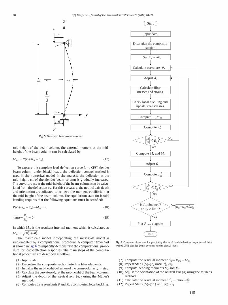
2
L
L um
'y
e
e
P
z
P
Fig. 5. Pin-ended beam-column model.
Start
Discretize the composite section
Set
Calculate curvature
Adjust dn
Calculate fiber stresses and strains
Compute P, M mi
Check local buckling and update steel stresses
Plot P-um diagram
Is Pn obtained?or um > limit?
End
Input data
Yes
Yes
No
Nommm uuu Δ+=
mm uu Δ=
mφ
Compute Mx and My
Adjust
No
Yes
θ
Compute bmr
?kbmr ε<
Compute amr
?ka
mr ε<
Fig. 6. Computer flowchart for predicting the axial load-deflection responses of thin-walled CFST slender beam-columns under biaxial loads.
68 Q.Q. Liang et al. / Journal of Constructional Steel Research 75 (2012) 64–71
mid-height of the beam-column, the external moment at the mid-height of the beam-column can be calculated by
Mme ¼ P eþ um þ uoð Þ ð17Þ
To capture the complete load-deflection curve for a CFST slenderbeam-column under biaxial loads, the deflection control method isused in the numerical model. In the analysis, the deflection at themid-height um of the slender beam-column is gradually increased.The curvature ϕm at the mid-height of the beam-column can be calcu-lated from the deflection um. For this curvature, the neutral axis depthand orientation are adjusted to achieve the moment equilibrium atthe mid-height of the beam-column. The equilibrium state for biaxialbending requires that the following equations must be satisfied:
P eþ um þ uoð Þ−Mmi ¼ 0 ð18Þ
tanα−My
Mx¼ 0 ð19Þ
in which Mmi is the resultant internal moment which is calculated as
Mmi ¼ffiffiffiffiffiffiffiffiffiffiffiffiffiffiffiffiffiffiffiffiM2
x þM2y
q.
The macroscale model incorporating the mesoscale model isimplemented by a computational procedure. A computer flowchartis shown in Fig. 6 to implicitly demonstrate the computational proce-dure for load-deflection responses. The main steps of the computa-tional procedure are described as follows:
(1) Input data.(2) Discretize the composite section into fine fiber elements.(3) Initialize themid-height deflection of the beam-column um=Δum.(4) Calculate the curvatureϕm at themid-height of the beam-column.(5) Adjust the depth of the neutral axis (dn) using the Müller's
method.(6) Compute stress resultants P andMmi considering local buckling.
(7) Compute the residual moment rma =Mme−Mmi.(8) Repeat Steps (5)–(7) until |rma |bεk.(9) Compute bending moments Mx and My.
(10) Adjust the orientation of the neutral axis (θ) using the Müller'smethod.
(11) Calculate the residual moment rbm ¼ tanα−My
Mx.
(12) Repeat Steps (5)–(11) until |rmb |bεk.
115

mm φφ Δ=
0=n
oa
P
mmm φφφ Δ+=
nnn PPP Δ+=
?kc
mr ε<
?kb
mr ε<
?ka
mr ε<
eφ
n
m
d
cmr
amr
eM miM
miM
bmr
θ
xM yM
n
n oa
n
n
Fig. 7. Computer flowchart for simulating the strength envelops of thin-walled CFSTslender beam-columns under biaxial loads.
69Q.Q. Liang et al. / Journal of Constructional Steel Research 75 (2012) 64–71
(13) Increase the deflection at the mid-height of the beam-columnby um=um+Δum.
(14) Repeat Steps (4)–(13) until the ultimate axial load Pn isobtained or the deflection limit is reached.
(15) Plot the load-deflection curve.
In the above procedure, εk is the convergence tolerance and takenas 10−4 in the numerical analysis.
3.2. Macroscale model for simulating strength envelopes
In design practice, it is required to check for the design capacitiesof CFST slender beam-columns under design actions such as the de-sign axial force and bending moments, which have been determinedfrom structural analysis. For this design purpose, the axial load-momentstrength interaction curves (strength envelopes) need to be developedfor the beam-columns. For a given axial load applied (Pn) at a fixed loadangle (α), the ultimate bending strength of a slender beam-column is de-termined as the maximum moment that can be applied to the columnends. The moment equilibrium is maintained at the mid-height of thebeam-column. The external moment at the mid-height of the slenderbeam-column is given by
Mme ¼ Me þ Pn um þ uoð Þ ð20Þ
inwhichMe is themoment at the column ends. The deflection at themid-height of the slender beam-column can be calculated from the curvatureas
um ¼ Lπ
� �2ϕm ð21Þ
To generate the strength envelope, the curvature (ϕm) at the mid-height of the beam-column is gradually increased. For each curvatureincrement, the corresponding internal moment capacity (Mmi) is com-puted by the inelastic moment-curvature responses discussed inSection 2.8. The curvature at the column ends (ϕe) is adjusted andthe corresponding moment at the column ends is calculated untilthe maximum moment at the column ends is obtained. The axialload is increased and the strength envelope can be generated by re-peating the above process. For a CFST slender beam-column undercombined axial load and bending, the following equilibrium equationsmust be satisfied:
Pn−P ¼ 0 ð22Þ
tan α−My
Mx¼ 0 ð23Þ
Me þ Pn um þ uoð Þ−Mmi ¼ 0 ð24Þ
Fig. 7 shows a computer flowchart that implicitly illustrates thecomputational procedure for developing the strength envelope. Themain steps of the computational procedure are described as follows:
(1) Input data.(2) Discretize the composite section into fine fiber elements.(3) The load-deflection analysis procedure is used to compute the
ultimate axial load Poa of the axially loaded slender beam-column with local buckling effects.
(4) Initialize the applied axial load Pn=0.(5) Initialize the curvature at the mid-height of the beam-column
ϕm=Δϕm.(6) Compute the mid-height deflection um from the curvature ϕm.(7) Adjust the depth of the neutral axis (dn) using the Müller's
method.(8) Calculate resultant force P considering local buckling.(9) Compute the residual force rm
c =Pn−P.
(10) Repeat Steps (7)–(9) until |rmc |bεk.(11) Compute bending moment Mx and My.(12) Adjust the orientation of the neutral axis (θ) using the Müller's
method.(13) Calculate the residual moment rbm ¼ tanα−My
Mx.
(14) Repeat Steps (7)–(13) until |rmb |bεk.(15) Compute the internal resultant moment Mmi.
116

70 Q.Q. Liang et al. / Journal of Constructional Steel Research 75 (2012) 64–71
(16) Adjust the curvature at the column end ϕe using the Müller'smethod.
(17) Compute the moment Me at the column ends accounting forlocal buckling effects.
(18) Compute rma =Mme−Mmi.
(19) Repeat Steps (16)–(18) until |rma |bεk.(20) Increase the curvature at the mid-height of the beam-column
by ϕm=ϕm+Δϕm.(21) Repeat Steps (6)–(20) until the ultimate bending strength
Mn(=Me max) at the column ends is obtained.(22) Increase the axial load by Pn=Pn+ΔPn, where ΔPn=Poa/10.(23) Repeat Steps (5)–(22) until the maximum load increment is
reached.(24) Plot the axial load-moment interaction diagram.
4. Numerical solution scheme
4.1. General
As discussed in the preceding sections, the depth and orientationof the neutral axis and the curvature at the column ends need to beiteratively adjusted to satisfy the force and moment equilibrium condi-tions in the inelastic analysis of a slender beam-column. For this pur-pose, computational algorithms based on the secant method havebeen developed by Liang [21,28]. Although the secant method algo-rithms are shown to be efficient and reliable for obtaining converged so-lutions, computational algorithms based on the Müller's method [35],which is a generalization of the secant method, are developed in thepresent study to determine the true depth and orientation of the neutralaxis and the curvature at the column ends.
4.2. The Müller's method
In general, the depth (dn) and orientation (θ) of the neutral axis andthe curvature (ϕe) at the column ends of a slender beam-column aredesign variables which are denoted herein by ω. The Müller's methodrequires three starting values of the design variables ω1, ω2, and ω3.The corresponding force or moment functions rm, 1, rm, 2 and rm, 3 arecalculated based on the three initial design variables. The new designvariableω4 that approaches the true value is determined by the follow-ing equations:
ω4 ¼ ω3 þ−2cm
bm �ffiffiffiffiffiffiffiffiffiffiffiffiffiffiffiffiffiffiffiffiffiffiffiffiffib2m−4amcm
q ð25Þ
am ¼ω2−ω3ð Þ rm;1−rm;3
� �− ω1−ω3ð Þ rm;2−rm;3
� �ω1−ω2ð Þ ω1−ω3ð Þ ω2−ω3ð Þ ð26Þ
bm ¼ω1−ω3ð Þ2 rm;2−rm;3
� �− ω2−ω3ð Þ2 rm;1−rm;3
� �ω1−ω2ð Þ ω1−ω3ð Þ ω2−ω3ð Þ ð27Þ
cm ¼ rm;3 ð28Þ
When adjusting the neutral axis depth and orientation, the sign ofthe square root term in the denominator of Eq. (25) is taken to be thesame as that of bm. However, this sign is taken as positive when adjust-ing the curvature at the column ends. In order to obtain converged so-lutions, the values of ω1, ω2 and ω3 and corresponding residual forcesor moments rm, 1, rm, 2 and rm, 3 need to be exchanged as discussed byPatel et al. [22]. Eq. (25) and the exchange of design variables andforce or moment functions are executed iteratively until the conver-gence criterion of |rm|bεk is satisfied.
In the numerical model, three initial values of the neutral axis depthdn, 1, dn, 3 and dn, 2 are taken as D/4, D and (dn, 1+dn, 3)/2 respectively;
the orientations of the neutral axis θ1, θ3 and θ2 are initialized to α/4,α and (θ1+θ3)/2 respectively; and the curvature at the column endsϕe, 1, ϕe, 3 and ϕe, 2 are initialized to 10−10, 10−6 and (ϕe, 1+ϕe, 3)/2respectively.
5. Performance indices for CFST slender beam-columns
Performance indices are used to evaluate the contributions of the con-crete and steel components to the ultimate strengths of CFST slenderbeam-columns and to quantify the strength reduction caused by the sec-tion and column slenderness, loading eccentricity and initial geometricimperfections. These performance indices can be used to investigate thecost effective designs of CFST slender beam-columns under biaxial loads.
5.1. Steel contribution ratio (ξs)
The steel contribution ratio is used to determine the contribution ofthe hollow steel tubular beam-column to the ultimate strength of theCFST slender beam-column under axial load and biaxial bending, whichis given by
ξs ¼Ps
Pnð29Þ
where Pn is the ultimate axial strength of the CFST slender beam-columnand Ps is the ultimate axial strength of the hollow steel tubular beam-column,which is calculated by setting the concrete compressive strengthf′c to zero in the numerical analysis while other conditions of the hollowsteel tubular beam-column remain the same as those of the CFST beam-column. The effects of local buckling are taken into account in the deter-mination of both Pn and Ps.
5.2. Concrete contribution ratio (ξc)
The concrete contribution ratio quantifies the contribution of theconcrete component to the ultimate axial strength of a CFST slenderbeam-column. The slender concrete core beam-column without rein-forcement carries very low loading and does not represents the concretecore in a CFST slender beam-column. Portolés et al. [9] used the capacityof the hollow steel tubular beam-column to define the concrete contri-bution ratio (CCR), which is given by
CCR ¼ Pn
Psð30Þ
Eq. (30) is an inverse of the steel contribution ratio andmay not accu-rately quantify the concrete contribution. To evaluate the contribution ofthe concrete component to the ultimate axial strength of a CFST slenderbeam-column, a new concrete contribution ratio is proposed as
ξc ¼Pn−Ps
Pnð31Þ
It can be seen from Eq. (31) that the concrete contribution to theultimate axial strength of a CFST slender beam-column is the differencebetween the ultimate axial strength of the CFST column and that of thehollow steel column.
5.3. Strength reduction factor (αc)
The ultimate axial strength of a CFST short column under axialloading is reduced by increasing the section and column slenderness,loading eccentricity, and initial geometric imperfections. To reflect onthese effects, the strength reduction factor is defined as
αc ¼Pn
Poð32Þ
117

71Q.Q. Liang et al. / Journal of Constructional Steel Research 75 (2012) 64–71
where Po is the ultimate axial strength of the column cross-sectionunder axial compression. The ultimate axial strengths of Pn and Poare determined by considering the effects of local buckling of thesteel tubes.
6. Conclusions
This paper has presented a new multiscale numerical model forthe nonlinear inelastic analysis of high strength thin-walled rectangularCFST slender beam-columns under combined axial load and biaxialbending. At the mesoscale level, the inelastic axial load-strain andmoment-curvature responses of column cross-sections subjected to bi-axial loads aremodeled using the accurate fiber elementmethod, whichaccounts for the effects of progressive local buckling of the steel tubewalls under stress gradients. Macroscale models together with compu-tational procedures have been described that simulate the axial load-deflection responses and strength envelopes of CFST slender beam-columns under biaxial bending. Initial geometric imperfections andsecond order effects between axial load and deformations are takeninto account in the macroscale models. New solution algorithms basedon the Müller's method have been developed and implemented in thenumerical model to obtain converged solutions.
The computer program that implements the multiscale numericalmodel developed is an efficient and powerful computer simulationand design tool that can be used to determine the structural performanceof biaxially loaded high strength rectangular CFST slender beam-columnsmade of compact, non-compact or slender steel sections. This overcomesthe limitations of experiments which are extremely expensive and timeconsuming. Moreover, the multiscale numerical model can be imple-mented in frame analysis programs for the nonlinear analysis of compos-ite frames. Steel and concrete contribution ratios and strength reductionfactor proposed can beused to study the optimal designs of high strengthCFST beam-columns. The verification of the numerical model and para-metric study are given in a companion paper [30].
References
[1] Furlong RW. Strength of steel-encased concrete beam-columns. J Struct Div ASCE1967;93(5):113–24.
[2] Knowles RB, Park R. Strength of concrete-filled steel tubular columns. J Struct DivASCE 1969;95(12):2565–87.
[3] Schneider SP. Axially loaded concrete-filled steel tubes. J Struct Eng ASCE1998;124(10):1125–38.
[4] Varma AH, Ricles JM, Sause R, Lu LW. Seismic behavior andmodeling of high-strengthcomposite concrete-filled steel tube (CFT) beam-columns. J Constr Steel Res 2002;58:725–58.
[5] Sakino K, Nakahara H, Morino S, Nishiyama I. Behavior of centrally loadedconcrete-filled steel-tube short columns. J Struct Eng ASCE 2004;130(2):180–8.
[6] Fujimoto T, Mukai A, Nishiyama I, Sakino K. Behavior of eccentrically loadedconcrete-filled steel tubular columns. J Struct Eng ASCE 2004;130(2):203–12.
[7] Ellobody E, Young B, Lam D. Behaviour of normal and high strength concrete-filledcompact steel tube circular stub columns. J Constr Steel Res 2006;62(7):706–15.
[8] Liu D. Behaviour of eccentrically loaded high-strength rectangular concrete-filledsteel tubular columns. J Constr Steel Res 2006;62(8):839–46.
[9] Portolés JM, Romero ML, Bonet JL, Filippou FC. Experimental study on highstrength concrete-filled circular tubular columns under eccentric loading. J ConstrSteel Res 2011;67(4):623–33.
[10] Ge HB, Usami T. Strength of concrete-filled thin-walled steel box columns: exper-iment. J Struct Eng ASCE 1992;118(11):3036–54.
[11] Bridge RQ, O'Shea MD. Behaviour of thin-walled steel box sections with or with-out internal restraint. J Constr Steel Res 1998;47(1–2):73–91.
[12] Uy B. Strength of concrete filled steel box columns incorporating local buckling. JStruct Eng ASCE 2000;126(3):341–52.
[13] Han LH. Tests on stub columns of concrete-filled RHS sections. J Constr Steel Res2002;58(3):353–72.
[14] Liang QQ, Uy B, Liew JYR. Local buckling of steel plates in concrete-filled thin-walled steel tubular beam-columns. J Constr Steel Res 2007;63(3):396–405.
[15] Liang QQ. High strength circular concrete-filled steel tubular slender beam-columns, part II: fundamental behavior. J Constr Steel Res 2011;67(2):172–80.
[16] Bridge RQ. Concrete filled steel tubular columns. School of Civil Engineering, TheUniversity of Sydney, Sydney, Australia, Research Report No. R283; 1976.
[17] Shakir-Khalil H, Zeghiche J. Experimental behaviour of concrete-filled rolledrectangular hollow-section columns. Struct Eng 1989;67(19):346–53.
[18] Shakir-Khalil H, Mouli M. Further tests on concrete-filled rectangular hollow-section columns. Struct Eng 1990;68(20):405–13.
[19] Vrcelj Z, Uy B. Strength of slender concrete-filled steel box columns incorporatinglocal buckling. J Constr Steel Res 2002;58(2):275–300.
[20] Hu HT, Huang CS, Wu MH, Wu YM. Nonlinear analysis of axially loaded concrete-filled tube columns with confinement effect. J Struct Eng ASCE 2003;129(10):1322–9.
[21] Liang QQ. High strength circular concrete-filled steel tubular slender beam-columns, part I: numerical analysis. J Constr Steel Res 2011;67(2):164–71.
[22] Patel VI, Liang QQ, Hadi MNS. High strength thin-walled rectangular concrete-filledsteel tubular slender beam-columns, part I: modeling. J Constr Steel Res 2012;70:377–84.
[23] Patel VI, Liang QQ, Hadi MNS. High strength thin-walled rectangular concrete-filled steel tubular slender beam-columns, part II: behavior. J Constr Steel Res2012;70:368–76.
[24] El-Tawil S, Sanz-Picon CF, Deierlein GG. Evaluation of ACI 318 and AISC (LRFD)strength provisions for composite beam-columns. J Constr Steel Res 1995;34(1):103–23.
[25] El-Tawil S, Deierlein GG. Strength and ductility of concrete encased compositecolumn. J Struct Eng 1999;125(9):1009–19.
[26] Muñoz PR, Hsu CTT. Behavior of biaxially loaded concrete-encased compositecolumns. J Struct Eng ASCE 1997;123(9):1163–71.
[27] Lakshmi B, Shanmugam NE. Nonlinear analysis of in-filled steel-concrete compos-ite columns. J Struct Eng ASCE 2002;128(7):922–33.
[28] Liang QQ. Performance-based analysis of concrete-filled steel tubular beam-columns, part I: theory and algorithms. J Constr Steel Res 2009;65(2):363–72.
[29] Liang QQ. Performance-based analysis of concrete-filled steel tubular beam-columns, part II: verification and applications. J Constr Steel Res 2009;65(2):351–62.
[30] Patel VI, Liang QQ, Hadi MNS. Biaxially loaded high-strength concrete-filled steeltubular slender beam-columns, part II: parametric study. J Constr Steel Ressubmitted for publication.
[31] Mander JB, Priestley MJN, Park R. Theoretical stress–strain model for confinedconcrete. J Struct Eng ASCE 1988;114(8):1804–26.
[32] ACI-318. Building code requirements for reinforced concrete. Detroit, MI: ACI;2002.
[33] Tomii M, Sakino K. Elastic–plastic behavior of concrete filled square steel tubularbeam-columns. Trans Archit Inst Japn 1979;280:111–20.
[34] Bulson PS. The stability of flat plates. London: Chatto and Windus; 1970.[35] Müller DE. A method for solving algebraic equations using an automatic computer.
MTAC 1956;10:208–15.
118

Chapter 4: Rectangular CFST Slender Beam-columns under Axial Load and Biaxial Bending
V. I. Patel: Nonlinear Inelastic Analysis of Concrete-Filled Steel Tubular Slender Beam-Columns 119
Revised manuscript prepared for
Journal of Constructional Steel Research
January 2012
Biaxially Loaded High-Strength Concrete-Filled Steel
Tubular Slender Beam-Columns, Part II: Parametric Study
Vipulkumar Ishvarbhai Patela, Qing Quan Liang
a,*, Muhammad N. S. Hadi
b
aSchool of Engineering and Science, Victoria University, PO Box 14428, Melbourne, VIC 8001, Australia
bSchool of Civil, Mining and Environmental Engineering, University of Wollongong,
Wollongong, NSW 2522, Australia
Corresponding author:
Dr. Qing Quan Liang School of Engineering and Science Victoria University PO Box 14428 Melbourne VIC 8001 Australia Phone: +61 3 9919 4134 Fax: +61 3 9919 4139 E-mail: [email protected]

Chapter 4: Rectangular CFST Slender Beam-columns under Axial Load and Biaxial Bending
V. I. Patel: Nonlinear Inelastic Analysis of Concrete-Filled Steel Tubular Slender Beam-Columns 120
Biaxially loaded high-strength concrete-filled steel tubular slender beam-columns, Part II: Parametric study
Vipulkumar Ishvarbhai Patela, Qing Quan Lianga,, Muhammad N. S. Hadib
a School of Engineering and Science, Victoria University, PO Box 14428, Melbourne,
VIC 8001, Australia b School of Civil, Mining and Environmental Engineering, University of Wollongong,
Wollongong, NSW 2522, Australia
ABSTRACT
Biaxially loaded high strength rectangular concrete-filled steel tubular (CFST) slender
beam-columns with large depth-to-thickness ratios, which may undergo local and global
interaction buckling, have received very little attention. This paper presents the
verification of a multiscale numerical model described in a companion paper and an
extensive parametric study on the performance of high strength thin-walled rectangular
CFST slender beam-columns under biaxial loads. Comparisons of computer solutions
with existing experimental results are made to examine the accuracy of the multiscale
numerical model developed. The effects of the concrete compressive strength, loading
eccentricity, depth-to-thickness ratio and columns slenderness on the ultimate axial
strength, steel contribution ratio, concrete contribution ratio and strength reduction
factor of CFST slender beam-columns under biaxial bending are investigated by using
the numerical model. Comparative results demonstrate that the multiscale numerical
model is capable of accurately predicting the ultimate strength and deflection behavior
Corresponding author. Tel.: 61 3 9919 4134; fax: +61 3 9919 4139. E-mail address: [email protected] (Q. Q. Liang)

Chapter 4: Rectangular CFST Slender Beam-columns under Axial Load and Biaxial Bending
V. I. Patel: Nonlinear Inelastic Analysis of Concrete-Filled Steel Tubular Slender Beam-Columns 121
of CFST slender beam-columns under biaxial loads. Benchmark numerical results
presented in this paper provide a better understanding of the local and global interaction
buckling behavior of high strength thin-walled CFST slender beam-columns and are
useful for the development of composite design codes.
Keywords: Biaxial bending; Concrete-filled steel tubes; High strength materials; Local
and post-local buckling; Nonlinear analysis; Slender beam-columns.
1. Introduction
High strength thin-walled rectangular concrete-filled steel tubular (CFST) slender
columns with large depth-to-thickness ratios are increasingly used in lateral load
resisting systems in high-rise composite buildings to resist heavy axial loads as well as
biaxial bending moments. These composite beam-columns are characterized by high
strength, large depth-to-thickness ratio, slenderness and biaxial bending. The failure
mode of thin-walled CFST slender beam-columns may involve interaction local and
global buckling, which significantly complicates their analysis and design procedures.
There has been a lack of experimental and numerical studies on this type of composite
columns so that their fundamental behavior has not been adequately understood.
Therefore, researches on the structural performance of high strength thin-walled CFST
slender beam-columns under biaxial bending are much needed. This paper is concerned
with numerical studies on the structural performance of biaxial loaded high strength
thin-walled CFST slender beam-columns incorporating the effects of local buckling of
the steel tube walls under stress gradients.

Chapter 4: Rectangular CFST Slender Beam-columns under Axial Load and Biaxial Bending
V. I. Patel: Nonlinear Inelastic Analysis of Concrete-Filled Steel Tubular Slender Beam-Columns 122
The performance of CFST short and slender columns under axial load or combined
axial load and uniaxial bending has been investigated experimentally by researchers [1-
7]. However, there have been relatively few experimental studies on the behavior of
biaxially loaded rectangular CFST slender beam-columns with large depth-to-thickness
ratios. Bridge [8] performed experiments on biaxially loaded normal strength square
CFST slender beam-columns. The main variables examined in the test program were the
loading eccentricity, column slenderness and biaxial bending. Test results showed that
the ultimate axial strength of CFST slender beam-columns decreased with increasing
the loading eccentricity or the column slenderness. Local buckling was not observed
because compact steel sections with a depth-to-thickness ratio of 20 were used.
Experimental studies were carried out by Shakir-Khalil and Zeghiche [9] and Shakir-
Khalil and Mouli [10] to determine the ultimate axial loads of normal strength
rectangular CFST slender beam-columns under axial load and biaxial bending. Tests
parameters examined included the section size, steel yield strength, concrete
compressive strength, column length and eccentricity of loading. The authors reported
that the relative load carrying capacity of the composite to steel columns increased
when the size of the steel section or the concrete compressive strength was increased.
However, they observed reversed influence for the loading eccentricity and column
length. The typical failure mode of these tested specimens was overall column buckling.
Recently, Guo et al. [11] undertook tests on normal strength rectangular CFST slender
beam-columns with rib stiffeners and under biaxial bending. Test results showed that
local buckling of the steel tube walls between the rib stiffeners occurred after specimens
attained their ultimate strengths.
Chapter 4: Rectangular CFST Slender Beam-columns under Axial Load and Biaxial Bending
V. I. Patel: Nonlinear Inelastic Analysis of Concrete-Filled Steel Tubular Slender Beam-Columns 123
Numerical analysis techniques have been used to study the nonlinear inelastic behavior
of short and slender composite columns under axial load and uniaxial bending [12-19].
Lakshmi and Shanmugam [20] used a semi-analytical model to determine the ultimate
axial strengths, load-deflection responses and strength envelopes of CFST columns
under axial load and biaxial bending. Their analytical results demonstrated that
increasing the loading eccentricity significantly reduced the ultimate axial strength and
stiffness of CFST slender columns. The semi-analytical model was used to develop the
strength envelopes of CFST cross-sections under uniaxial bending. However, the
strength envelopes of thin-walled CFST slender beam-columns under biaxial bending
have not been investigated by Lakshmi and Shanmugam [20]. In addition, the effects of
local buckling were not taken into account in their model and numerical studies. Liang
[21, 22] employed a performance-based analysis technique accounting for progressive
local buckling of the steel tube walls [23] to investigate the effects of the depth-to-
thickness ratio, concrete compressive strength, steel yield strength and axial load level
on the ultimate axial strengths, load-strain behavior, moment-curvature responses and
strength envelopes of thin-walled CFST short columns under axial load and biaxial
bending. However, numerical studies on the behavior of biaxially loaded high strength
CFST slender beam-columns with local buckling effects have not been reported in the
literature.
The purpose of this paper is to validate the multiscale numerical model presented in a
companion paper [24] and to study the structural performance of high strength CFST
slender beam-columns made of slender steel sections. Verification studies involve
thorough and comprehensive comparisons of the predicted ultimate axial loads, ultimate

Chapter 4: Rectangular CFST Slender Beam-columns under Axial Load and Biaxial Bending
V. I. Patel: Nonlinear Inelastic Analysis of Concrete-Filled Steel Tubular Slender Beam-Columns 124
bending strengths and complete load-deflection responses of CFST slender beam-
columns to existing experimental results. The parametric study focuses on the ultimate
axial strength, steel contribution ratio, concrete contribution ratio, strength reduction
factor and strength envelopes of high strength thin-walled CFST slender beam-columns
under biaxial loads. The paper is organized as follows. In section 2, the verification of
the numerical model is presented. This is followed by an extensive parametric study on
the fundamental behavior of high strength thin-walled CFST slender beam-columns.
Finally, important conclusions are given.
2. Verification of the multiscale numerical model
To verify the accuracy of the multiscale numerical model developed, the predicted
ultimate strengths and axial load-deflection responses of biaxially loaded CFST slender
beam-columns are compared with existing experimental results in this section.
2.1 Ultimate axial strengths of CFST slender beam-columns
The geometry and material properties of biaxially loaded CFST slender beam-columns
tested by independent researchers are given in Table 1. Experiments on specimens
SCH-3, SCH-4, SCH-5 and SCH-6 were conducted by Bridge [8]. These column
sections with a depth-to-thickness ratio tD of 20 were considered to be compact. The
ultimate tensile strength suf of steel tubes was assumed to be 430 MPa. Experimental
results on specimen R6 in Table 1 were given by Shakir-Khalil and Zeghiche [9]. The
axial load was applied at eccentricities of 16 mm and 24 mm about the major and minor

Chapter 4: Rectangular CFST Slender Beam-columns under Axial Load and Biaxial Bending
V. I. Patel: Nonlinear Inelastic Analysis of Concrete-Filled Steel Tubular Slender Beam-Columns 125
axis respectively. Specimens M2-M9 shown in Table 1 were tested by Shakir-Khalil
and Mouli [10]. The concrete cylinder compressive strength 'cf shown in Table 1 was
taken as 0.85 times the concrete cube strength. Initial geometric imperfections ou at
the mid-height of specimens R6 and M2-M9 were not measured. To consider this effect,
the initial geometric imperfection of 600L at the mid-height of the columns as
suggested by Portolés et al. [17] was taken into account in the present numerical
analysis.
Ultimate axial strengths obtained from experiments )( exp.nP and numerical analyses
)( num.nP are compared in Table 1. It can be seen from Table 1 that there is a good
agreement between computational solutions and experimental results. The mean value
of exp.num. nn PP ratio is 1.01 with a standard deviation (SD) of 0.05 and a coefficient of
variation (COV) of 0.05. This comparative study demonstrates that the macroscale
model for simulating the load-deflection responses can accurately predict the ultimate
axial strengths of CFST slender beam-columns under biaxial loads. It should be noted
that the numerical model for high strength CFST slender beam-columns under axial
load and uniaxial bending has been validated by Liang [21] and Patel et al. [18].
2.2 Ultimate bending strengths of CFST slender beam-columns
The ultimate bending strengths of CFST slender beam-columns were determined using
the macroscale model for simulating strength envelopes and compared with
experimental results presented by Bridge [8], Shakir-Khalil and Zeghiche [9] and

Chapter 4: Rectangular CFST Slender Beam-columns under Axial Load and Biaxial Bending
V. I. Patel: Nonlinear Inelastic Analysis of Concrete-Filled Steel Tubular Slender Beam-Columns 126
Shakir-Khalil and Mouli [10]. The initial geometric imperfection of 600L at the mid-
height of the columns was taken into account in the numerical analysis if it was not
measured in the tests. The experimental ultimate axial loads were used in numerical
analyses to determine the corresponding ultimate bending strengths. Computational and
experimental ultimate bending strengths obtained are given in Table 2, where the
experimental ultimate bending strength exp.nM was calculated as ePM un exp.exp. . It
can be seen from Table 2 that numerical predictions are in good agreement with
experimental results. The ratio of the mean ultimate bending strength computed by the
numerical model to the experimental value is 1.0. The standard deviation (SD) of the
ratio is 0.08 while the coefficient of variation (COV) is 0.07. This comparison shows
that the macroscale model for strength envelopes can yield accurate predictions of the
ultimate bending strengths of biaixally loaded CFST slender beam-columns.
2.3 Load-deflection responses
The numerical model was used to predict the load-deflection responses of specimens
tested by by Bridge [8]. Fig. 1 shows a comparison of experimental and computational
load-deflection curves for specimen SCH-3. The figure demonstrates that numerical
results are in excellent agreement with experimentally observed behaviors. It is noted
that the initial stiffness of the tested specimen slightly differs from that predicted by the
numerical model. This is likely attributed to the uncertainty of the actual concrete
stiffness and strength as the average concrete compressive strength was used in the
numerical analysis. It can be seen from Fig. 2 that the numerical model predicts well the
load-deflection curve for the tested specimen SCH-6 up to the ultimate axial load. The

Chapter 4: Rectangular CFST Slender Beam-columns under Axial Load and Biaxial Bending
V. I. Patel: Nonlinear Inelastic Analysis of Concrete-Filled Steel Tubular Slender Beam-Columns 127
predicted initial stiffness of the column is almost identical to that of the experimentally
observed value. However, the experimental load-deflection curve slightly differs from
the computed one at the axial load higher than 600 kN. This is likely caused by the
uncertainty of the actual concrete stiffness and strength of the specimen.
3. Parametric study
Parametric studies were carried out to examine the effects of concrete compressive
strength, loading eccentricity, depth-to-thickness ratio and column slenderness on the
ultimate axial strength, steel contribution ratio, concrete contribution ratio and strength
reduction factor of full-scale high strength CFST slender beam-columns under axial
load and biaxial bending. In the present study, the initial geometric imperfection at the
mid-height of the beam-column was taken as 1000/L . The yield and tensile strengths of
the steel were 690 MPa and 790 MPa respectively while the Young’s modulus of steel
material was 200 GPa. The effects of local and post-local buckling were considered in
all analyses.
3.1 Ultimate axial strengths
The ultimate axial strengths of high strength CFST slender beam-columns under axial
load and biaxial bending were determined by performing load-deflection analyses. The
beam-columns with a cross-section of 700 × 700 mm and under the eccentric load
applied at an angle of 60°with respect to the y-axis were analyzed. The following basic
parameters were specified in the parametric study. The loading eccentricity ratio De
Chapter 4: Rectangular CFST Slender Beam-columns under Axial Load and Biaxial Bending
V. I. Patel: Nonlinear Inelastic Analysis of Concrete-Filled Steel Tubular Slender Beam-Columns 128
was 0.4. The concrete compressive strength was 80 MPa. The column slenderness ratio
rL of 60 and depth-to-thickness ratio tD of 70 were used in parametric study.
Each parameter was varied to examine its individual effects on the ultimate axial
strengths.
Fig. 3 shows the effects of concrete compressive strengths ranging from 25 to 120 MPa
on the ultimate axial strengths of high strength thin-walled CFST slender beam-
columns. It can be seen from Fig. 3 that increasing the concrete compressive strength
significantly increases the ultimate axial strengths of biaxially loaded slender beam-
columns. When increasing the concrete compressive strength from 30 MPa to 70 MPa
and 120 MPa, the ultimate axial strength is found to increase by 32.2% and 59.6%,
respectively. The ultimate axial load ratio is described in Fig. 4 as a function of the
loading eccentricity ratio ranging from zero to 2.0. As shown in Fig. 4, the ultimate
axial strength of the slender beam-column under eccentric loading nP was normalized
by the ultimate axial load of the slender column under axial compression oaP . It can be
observed from Fig. 4 that the ultimate axial strength of a CFST slender beam-column is
significantly reduced by increasing the loading eccentricity ratio. For the end
eccentricity ratios of zero and 2.0, the axial load ratios are 1.0 and 0.103 respectively.
The effects of tD ratio ranging from 20 to 100 on the ultimate axial loads of CFST
slender beam-columns are demonstrated in Fig. 5. The figure illustrates that increasing
the tD ratio remarkably reduces the ultimate axial loads of CFST slender beam-
columns under biaxial loads. When the tD ratio increases from 20 to 60 and 100, the
reduction in the ultimate axial strength of the slender beam-columns is 50% and 64.1%,

Chapter 4: Rectangular CFST Slender Beam-columns under Axial Load and Biaxial Bending
V. I. Patel: Nonlinear Inelastic Analysis of Concrete-Filled Steel Tubular Slender Beam-Columns 129
respectively. The relationship between the ultimate axial strength and the column
slenderness ratio ranging from zero to 100 is demonstrated in Fig. 6, where osP is the
ultimate axial strength of the cross-section under eccentric loading. It would appear
from Fig. 6 that increasing the column slenderness ratio causes a significant reduction in
the ultimate axial load of the beam-column. The ultimate axial load ratio is 0.93, 0.71
and 0.39 for the columns with a rL ratio of 20, 50 and 100 respectively.
3.2 Steel contribution ratio
The numerical model was employed to study the effects of various parameters on the
steel contribution ratio which is defined as the calculated ultimate axial strength of the
slender hollow steel tube to the ultimate axial strength of the CFST slender beam-
column [24]. A thin-walled CFST beam-column with a cross-section of 700 × 800 mm
was considered. The axial load was applied at an angle of 45° for biaxial bending. For
this case, the basic parameters were the depth-to-thickness ratio of 50, loading
eccentricity ratio of 0.4, slenderness ratio of 35 and the concrete compressive strength
of 90 MPa. Each of these parameters was varied to quantify its individual effects on the
steel contribution ratio.
The relationship between the steel contribution ratio and the concrete compressive
strength ranging from 25 to 120 MPa obtained by the numerical model is demonstrated
in Fig. 7. The figure shows that the use of higher strength concrete in CFST slender
beam-columns results in a remarkable decrease in the steel contribution ratio. This is
because increasing the concrete compressive strength significantly increases the
Chapter 4: Rectangular CFST Slender Beam-columns under Axial Load and Biaxial Bending
V. I. Patel: Nonlinear Inelastic Analysis of Concrete-Filled Steel Tubular Slender Beam-Columns 130
ultimate axial strength of the CFST beam-column but has not effect on the strength of
the hollow steel tube. The steel contribution ratio of a CFST slender beam-column with
concrete compressive strength of 35 MPa is 0.70, while it is only 0.48 for a CFST
slender beam-column with the concrete compressive strength of 120 MPa. Fig. 8
illustrates that the steel contribution ratio is a function of the loading eccentricity ratio
ranging from zero to 2.0. It can be observed from Fig. 8 that the larger the loading
eccentricity, the higher the steel contribution ratio. This is attributed to the fact that the
ultimate axial strengths of both the hollow steel tube and the CFST column are reduced
by increasing the loading eccentricity, but the CFST column has a greater reduction in
its ultimate axial strength than the hollow steel tube. For loading eccentricity ratio of 0.0
and 2.0, the steel contribution ratio of a slender CFST beam-column is 0.41 and 0.75
respectively.
Fig. 9 presents the steel contribution ratio of CFST columns with D/t ratios ranging
from 20 to 100. It can be seen from the figure that the steel contribution ratio decreases
with an increase in the depth-to-thickness ratio. This means that the reduction in the
ultimate axial strength of the hollow steel tube is greater than that in the one filled with
concrete due to the same increase in the D/t ratio. In other words, the D/t ratio has a
lesser effect on the capacity of CFST columns than on the hollow steel tubes. For depth-
to-thickness ratio of 20, 40 and 100, the steel contribution ratio is 0.76, 0.59 and 0.30
respectively. The relationship between the steel contribution ratio and the column
slenderness ratio ranging from 5 to 100 is shown in Fig. 10. The figure shows that the
more slender of the CFST beam-column, the more contribution of the steel tube to the
capacity of the CFST beam-column. It is noted that increasing the column slenderness

Chapter 4: Rectangular CFST Slender Beam-columns under Axial Load and Biaxial Bending
V. I. Patel: Nonlinear Inelastic Analysis of Concrete-Filled Steel Tubular Slender Beam-Columns 131
significantly reduces the ultimate axial strengths of both the hollow steel tube and CFST
column, but the reduction in the CFST column is greater than that in the hollow steel
tube. The steel contribution ratio is 0.5, 0.57 and 0.65 for the column with the column
slenderness ratio rL of 20, 50 and 100 respectively.
3.3 Concrete contribution ratio
The concrete contribution ratio, which is defined as nsn PPP )( [24], was studied using
the numerical model. Numerical analyses were undertaken on thin-walled CFST slender
beam-columns with a cross-section of 600 × 600 mm and under the axial load applied at
an angle of 30° with respect to the y-axis. The basic parameters examined in the study
included the depth-to-thickness ratio of 60, loading eccentricity ratio of 0.4 and the
slenderness ratio of 40 and the concrete compressive strength of 100 MPa.
The concrete contribution ratios of thin-walled CFST slender beam-columns with
concrete compressive strengths ranging from 25 to 120 MPa are given in Fig. 11. The
figure demonstrates that increasing the concrete compressive strength significantly
increases the concrete contribution ratio. This implies that the axial strength
performance of a CFST slender beam-column can be improved significantly by using
high strength concrete as infill. The calculated concrete contribution ratio for the
concrete compressive strength of 25 MPa, 75 MPa and 120 MPa is 0.29, 0.51 and 0.60
respectively. The concrete contribution curve is described in Fig. 12 as a function of the
loading eccentricity ratio ranging from zero to 2.0. It appears from Fig. 12 that the
concrete component has a lesser contribution to the ultimate axial strength of a CFST

Chapter 4: Rectangular CFST Slender Beam-columns under Axial Load and Biaxial Bending
V. I. Patel: Nonlinear Inelastic Analysis of Concrete-Filled Steel Tubular Slender Beam-Columns 132
slender beam-column when subjected to a larger loading eccentricity. To increase the
axial load capacity of CFST slender beam-columns with a large loading eccentricity, the
steel area and strength should be increased rather than the concrete. The concrete
contribution ratio of the rectangular CFST slender beam-column with a zero eccentricity
is 0.68, while it is only 0.36 with a De ratio of 2.0.
The effects of the tD ratio ranging from 20 to 100 on the concrete contribution ratio of
biaxially loaded CFST slender beam-columns are shown in Fig. 13. The concrete
contribution ratio is found to increase significantly with an increase in the tD ratio.
This may be explained by the fact that increasing the D/t ratio reduces the axial load
capacity of the steel tube and increases the cross-sectional area of the concrete core,
thereby increasing the contribution of the concrete component. The concrete
contribution ratio of the CFST slender beam-column with a tD ratio of 20 is 0.28,
while it is 0.73 for the column with a tD ratio of 100. Fig. 14 presents the results of
the concrete contribution ratios calculated by varying the column slenderness ratios
ranging from zero to 100. It appears that the concrete contribution to the ultimate axial
strength of CFST slender beam-columns decreases when increasing the column
slenderness ratio.
3.4 Strength reduction factor
In Eurocode 4 [25], the strength reduction factor is used to account for the effect of
column slenderness in the calculation of the ultimate axial load of a slender composite
column under axial compression. In this section, the strength reduction factor [24] was

Chapter 4: Rectangular CFST Slender Beam-columns under Axial Load and Biaxial Bending
V. I. Patel: Nonlinear Inelastic Analysis of Concrete-Filled Steel Tubular Slender Beam-Columns 133
studied by varying the concrete compressive strengths, loading eccentricity, depth-to-
thickness ratio and column slenderness. Biaxially loaded CFST slender beam-columns
with the cross-section of 600 × 700 mm were considered. The angle of the applied axial
load was 45°. The basic parameters studied were the depth-to-thickness ratio of 70,
loading eccentricity ratio of 0.4, the column slenderness ratio of 100 and concrete
compressive strength of 110 MPa. Each parameter was varied to examine its effects on
the strength reduction factor.
Fig. 15 presents a strength reduction factor curve as a function of the concrete
compressive strength ranging from 25 to 120 MPa. The figure indicates that increasing
the concrete compressive strength considerably reduces the strength reduction factor of
CFST slender beam-columns. It should be noted that the concrete compressive strength
has a pronounced effect on the axial strength of a CFST column section but has a lesser
effect on slender columns. When the concrete compressive strength is increased from 30
MPa to 60 MPa, 90MPa and 120 MPa, the strength reduction factor is found to be
reduced from 0.25 to 0.20, 0.17 and 0.15 respectively. The strength reduction factors
were obtained by varying the loading eccentricity ratio from zero to 2.0. Fig. 16 clearly
shows that a large loading eccentricity leads to a significant reduction in the ultimate
axial strength of a CFST slender beam-column.
Fig. 17 demonstrates the effects of the tD ratio ranging from 20 to 100 on the strength
reduction factor of slender beam-columns. It can be observed from the figure that the
strength reduction factor decreases considerably with an increase in the tD ratio of the
same size cross-section. It is known that increasing the D/t ratio causes a reduction in

Chapter 4: Rectangular CFST Slender Beam-columns under Axial Load and Biaxial Bending
V. I. Patel: Nonlinear Inelastic Analysis of Concrete-Filled Steel Tubular Slender Beam-Columns 134
the ultimate axial strengths of both the section and the CFST slender beam-column.
However, the D/t ratio has a lesser effect on the strength of a slender beam-column than
on its cross-section. The strength reduction factor is 0.19, 0.17 and 0.14 for the column
with tD ratio of 20, 50 and 100 respectively. The strength reduction factor of the
slender beam-columns was determined by varying the column slenderness ratio ranging
from zero to 100 and the results are presented in Fig. 18. The figure indicates that the
column slenderness has a pronounced effect on the ultimate axial strengths of CFST
beam-columns. The strength reduction factor is significantly reduced by increasing the
column slenderness ratio. The strength reduction factor of CFST columns under biaxial
bending with the column slenderness ratio of 10, 50 and 100 is 0.41, 0.29 and 0.15
respectively.
3.5 Strength envelopes
The inelastic stability analyses of high strength thin-walled CFST slender beam-
columns were undertaken to examine the effects of the column slenderness ratio on the
strength envelopes. The cross-section of 500 × 500 mm was considered. The tD ratio
of the high strength steel tube was 50. The beam-column was filled with high strength
concrete of 120 MPa. The angle of the axial load was fixed at 60° with respect to the y-
axis. The eccentricity ratio De of 0.4 was considered.
The strength envelopes of rectangular CFST beam-columns with the column
slenderness ratios of 0.0, 22 and 30 are presented in Fig. 19. The ultimate axial strength
was normalized to the ultimate axial load of the axially loaded column oaP while the

Chapter 4: Rectangular CFST Slender Beam-columns under Axial Load and Biaxial Bending
V. I. Patel: Nonlinear Inelastic Analysis of Concrete-Filled Steel Tubular Slender Beam-Columns 135
ultimate moment was normalized to the ultimate pure bending moment of the beam-
column oM . The curve for 0rL represents the strength envelope of the composite
section which is not affected by the global stability analysis. It appears from Fig. 19 that
reducing the rL ratio of the beam-column enlarges the normalized the strength
envelope of the beam-column. For beam-columns under the same axial load level,
increasing the column slenderness ratio rL reduces the ultimate bending strengths.
4. Conclusions
The verification of a multiscale numerical model and an extensive parametric study on
the behavior of high strength thin-walled rectangular CFST slender beam-columns
under axial load and biaxial bending and with local buckling effects have been
presented in this paper. Verification studies were undertaken by comparing
computational ultimate axial loads, ultimate bending strengths and complete load-
deflection responses of CFST slender beam-columns to experimentally observed
behavior reported by other researchers. Good agreement between computer solutions
and experimental results was obtained. The fundamental behavior of high strength thin-
walled CFST slender beam-columns under biaxial loads was described, including the
ultimate axial strength, steel contribution ratio, concrete contribution ratio, strength
reduction factor and strength envelope. It has been demonstrated that the ultimate
strength and behavior of high strength thin-walled CFST slender beam-columns under
biaxial bending are affected by many parameters including the concrete strength,
loading eccentricity, depth-to-thickness ratio and column slenderness. The design
methods given current composite design codes may yield very conservative designs of

Chapter 4: Rectangular CFST Slender Beam-columns under Axial Load and Biaxial Bending
V. I. Patel: Nonlinear Inelastic Analysis of Concrete-Filled Steel Tubular Slender Beam-Columns 136
biaxially loaded high strength thin-walled CFST slender beam-columns with local
buckling effects. Benchmark numerical results presented in this paper overcome the
limitations of current composite design codes and are useful not only for the design of
CFST slender beam-columns but also for validating other numerical models.
References
[1] Ge HB, Usami T. Strength of concrete-filled thin-walled steel box columns:
Experiment. Journal of Structural Engineering, ASCE 1992; 118(11):3036-54.
[2] Schneider SP. Axially loaded concrete-filled steel tubes. Journal of Structural
Engineering, ASCE 1998; 124(10):1125-38.
[3] Liu D, Gho WM, Yuan J. Ultimate capacity of high-strength rectangular concrete-
filled steel hollow section stub columns. Journal of Constructional Steel Research
2003; 59(12): 1499-1515.
[4] Varma AH, Ricles JM, Sause R, Lu LW. Seismic behavior and design of high-
strength square concrete-filled steel tube beam–columns. Journal of Structural
Engineering, ASCE 2004; 130(2):169-179.
[5] Sakino K, Nakahara H, Morino S, Nishiyama I. Behavior of centrally loaded
concrete-filled steel-tube short columns. Journal of Structural Engineering, ASCE
2004; 130(2):180-88.
[6] Young B, Ellobody E. Experimental investigation of concrete-filled cold-formed
high strength stainless steel tube columns. Journal of Constructional Steel
research 2006; 62(5):484-492.

Chapter 4: Rectangular CFST Slender Beam-columns under Axial Load and Biaxial Bending
V. I. Patel: Nonlinear Inelastic Analysis of Concrete-Filled Steel Tubular Slender Beam-Columns 137
[7] Han LH, Liu W, Yang YF. Behaviour of concrete-filled steel tubular stub
columns subjected to axially local compression. Journal of Constructional Steel
Research 2008; 64(4):377-387.
[8] Bridge RQ. Concrete filled steel tubular columns. School of Civil Engineering,
The University of Sydney, Sydney, Australia, 1976, Research Report No. R 283.
[9] Shakir-Khalil H, Zeghiche J. Experimental behaviour of concrete-filled rolled
rectangular hollow-section columns. The structural Engineer 1989; 67(19): 346-
53.
[10] Shakir-Khalil H, Mouli M. Further tests on concrete-filled rectangular hollow-
section columns. The structural Engineer 1990; 68(20): 405-13.
[11] Guo L, Zhang S, Xu Z. Behaviour of filled rectangular steel HSS composite
columns under bi-axial bending. Advances in Structural Engineering 2011; 14(2):
295-306.
[12] El-Tawil S, Sanz-Picón CF, Deierlein GG. Evaluation of ACI 318 and AISC
(LRFD) strength provisions for composite beam-columns. Journal of
Constructional Steel Research 1995; 34(1):103-23.
[13] Hu HT, Huang CS, Chen ZL. Finite element analysis of CFT columns subjected
to an axial compressive force and bending moment in combination. Journal of
Constructional Steel Research 2005; 61(12):1692-1712.
[14] Dai X, Lam D. Numerical modeling of the axial compressive behaviour of short
concrete-filled elliptical steel columns. Journal of Constructional Steel research
2010; 66(7):931-942.

Chapter 4: Rectangular CFST Slender Beam-columns under Axial Load and Biaxial Bending
V. I. Patel: Nonlinear Inelastic Analysis of Concrete-Filled Steel Tubular Slender Beam-Columns 138
[15] Liang QQ. High strength circular concrete-filled steel tubular slender beam-
columns, Part I: Numerical analysis. Journal of Constructional Steel Research
2011; 67(2): 164-171.
[16] Liang QQ. High strength circular concrete-filled steel tubular slender beam-
columns, Part II: Fundamental behavior. Journal of Constructional Steel Research
2011; 67(2): 172-180.
[17] Portolés JM, Romero ML, Filippou FC, Bonet JL. Simulation and design
recommendations of eccentrically loaded slender concrete-filled tubular columns.
Engineering Structures 2011; 33(5): 1576-93.
[18] Patel VI, Liang QQ, Hadi MNS. High strength thin-walled rectangular concrete-
filled steel tubular slender beam-columns, Part I: Modeling. Journal of
Constructional Steel Research 2012; 70:377-384.
[19] Patel VI, Liang QQ, Hadi MNS. High strength thin-walled rectangular concrete-
filled steel tubular slender beam-columns, Part II: Behavior. Journal of
Constructional Steel Research 2012; 70:368-376.
[20] Lakshmi B, Shanmugam NE. Nonlinear analysis of in-filled steel-concrete
composite columns. Journal of Structural Engineering, ASCE 2002; 128(7): 922-
33.
[21] Liang QQ. Performance-based analysis of concrete-filled steel tubular beam-
columns, Part I: Theory and algorithms. Journal of Constructional Steel research
2009; 65(2): 363-72.
[22] Liang QQ. Performance-based analysis of concrete-filled steel tubular beam-
columns, Part II: Verification and applications. Journal of Constructional Steel
research 2009; 65(2): 351-62.

Chapter 4: Rectangular CFST Slender Beam-columns under Axial Load and Biaxial Bending
V. I. Patel: Nonlinear Inelastic Analysis of Concrete-Filled Steel Tubular Slender Beam-Columns 139
[23] Liang QQ, Uy B, Liew JYR. Local buckling of steel plates in concrete-filled thin-
walled steel tubular beam-columns. Journal of Constructional Steel Research
2007; 63(3):396-405.
[24] Liang QQ, Patel VI, Hadi MNS. Biaxially loaded high-strength concrete-filled
steel tubular slender beam-columns, Part I: Multiscale simulation. Journal of
Constructional Steel Research 2011 (submitted).
[25] EN 1994-1-1, Eurocode 4: design of composite steel and concrete structures. Part
1-1, General rules and rules for buildings, CEN 2004.

Chapter 4: Rectangular CFST Slender Beam-columns under Axial Load and Biaxial Bending
V. I. Patel: Nonlinear Inelastic Analysis of Concrete-Filled Steel Tubular Slender Beam-Columns 140
Figures and tables
Table 1. Ulatimate axial strengths of biaxially loaded CFST slender beam-columns.
Specimens tDB (mm)
tD L (mm)
xe
(mm) ye
(mm) e
(mm)
( )
ou
(mm)
'cf
(MPa) syf
(MPa) suf
(MPa) sE
(GPa) exp.uP
(kN) numuP .
(kN) exp.
.
u
numup
P Ref.
SCH-3 200× 200 × 10.03 20 2130 38 60 0.79 37.2 313 430 205 2180 2201.1 1.01
[8] SCH-4 200× 200 × 9.88 20 2130 38 45 0.56 39.2 317 430 205 2162 2259.2 1.04
SCH-5 200× 200 × 10.01 20 3050 38 60 0.28 44.3 319 430 205 2037 2135.2 1.05
SCH-6 200× 200 × 9.78 20 3050 64 45 1.12 36.1 317 430 205 1623 1601.2 0.99
R6 80×120 × 5 24 3210 16 24 28.84 33.69 38.25 343.3 430 205 268 271.5 1.01 [9]
M2 80×120 × 5 24 3210 8 12 14.42 33.69 36.21 341 430 205 348 331.5 0.95
[10]
M3 80×120 × 5 24 3210 28 42 50.48 33.69 39.27 341 430 205 198.5 212.9 1.07
M4 80×120 × 5 24 3210 40 24 46.65 59.03 36.04 362.5 430 205 206.8 197.1 0.95
M5 80×120 × 5 24 3210 16 60 62.10 14.93 34.68 362.5 430 205 209.8 228.6 1.09
M7 100×150 × 5 30 3210 10 15 18.03 33.69 39.27 346.7 430 209.6 596.2 569.9 0.96
M9 100×150 × 5 30 3210 50 75 90.14 33.69 40.12 340 430 208.6 254.6 270.9 1.06
Mean 1.01
Standard deviation (SD) 0.05
Coefficient of variation (COV) 0.05
Table 2. Ultimate bending strengths of biaxially loaded CFST slender beam-columns.
pecimens tDB (mm)
tD L (mm)
xe
(mm) ye
(mm)
e (mm)
( )
ou
(mm)
'cf
(MPa) syf
(MPa) suf
(MPa) sE
(GPa) exp.nM
(kNm) numnM .
(kNm) exp.n
num.n
MM
Ref.
SCH-3 200× 200 × 10.03 20 2130 38 60 0.79 37.2 313 430 205 82.84 85.32 1.03 [8]
SCH-6 200× 200 × 9.78 20 3050 64 45 1.12 36.1 317 430 205 103.87 101.03 0.97
R6 80×120 × 5 24 3210 16 24 28.84 33.69 38.25 343.3 430 205 7.73 8.00 1.03 [9]
M4 80×120 × 5 24 3210 40 24 46.65 59.03 36.04 362.5 430 205 9.65 8.66 0.90 [10]
M9 100×150 × 5 30 3210 50 75 90.14 33.69 40.12 340 430 208.6 22.95 25.15 1.10
Mean 1.00
Standard deviation (SD) 0.08
Coefficient of variation (COV) 0.07

Chapter 4: Rectangular CFST Slender Beam-columns under Axial Load and Biaxial Bending
V. I. Patel: Nonlinear Inelastic Analysis of Concrete-Filled Steel Tubular Slender Beam-Columns 141
Fig. 1. Comparison of computational and experimental axial load-deflection curves for specimen SCH-3.
Fig. 2. Comparison of predicted and experimental axial load-deflection curves for specimen SCH-6.
0
500
1000
1500
2000
2500
0 5 10 15 20 25 30
Axi
al lo
ad (k
N)
Mid-height deflection um (mm)
Experiment
Numerical analysis
0
200
400
600
800
1000
1200
1400
1600
1800
0 5 10 15 20 25 30 35 40
Axi
al lo
ad (k
N)
Mid-height deflection um (mm)
Experiment
Numerical analysis

Chapter 4: Rectangular CFST Slender Beam-columns under Axial Load and Biaxial Bending
V. I. Patel: Nonlinear Inelastic Analysis of Concrete-Filled Steel Tubular Slender Beam-Columns 142
Fig. 3. Effects of concrete compressive strengths on the ultimate axial loads.
Fig. 4. Effects of De ratio on the ultimate axial loads.
0
2000
4000
6000
8000
10000
12000
14000
16000
18000
0 20 40 60 80 100 120 140
Ulti
mat
e axi
al lo
ad P
n (k
N)
Concrete compressive strength (MPa)
0
0.2
0.4
0.6
0.8
1
1.2
0 0.5 1 1.5 2 2.5
Ulti
mat
e axi
al lo
ad P
u/Poa
Eccentricity ratio e/D

Chapter 4: Rectangular CFST Slender Beam-columns under Axial Load and Biaxial Bending
V. I. Patel: Nonlinear Inelastic Analysis of Concrete-Filled Steel Tubular Slender Beam-Columns 143
Fig. 5. Effects of tD ratio on the ultimate axial loads.
Fig. 6. Effects of column slenderness ratio on the ultimate axial loads.
0
5000
10000
15000
20000
25000
30000
35000
0 20 40 60 80 100 120
Ulti
mat
e axi
al lo
ad P
n (k
N)
Depth-to-thickness ratio D/t
0
0.2
0.4
0.6
0.8
1
1.2
0 20 40 60 80 100 120
Ulti
mat
e axi
al lo
ad P
u/Pos
Column slendress ratio L/r
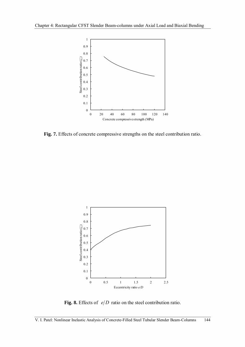
Chapter 4: Rectangular CFST Slender Beam-columns under Axial Load and Biaxial Bending
V. I. Patel: Nonlinear Inelastic Analysis of Concrete-Filled Steel Tubular Slender Beam-Columns 144
Fig. 7. Effects of concrete compressive strengths on the steel contribution ratio.
Fig. 8. Effects of De ratio on the steel contribution ratio.
0
0.1
0.2
0.3
0.4
0.5
0.6
0.7
0.8
0.9
1
0 20 40 60 80 100 120 140
Stee
l con
tribu
tion r
atio
(ξs)
Concrete compressive strength (MPa)
0
0.1
0.2
0.3
0.4
0.5
0.6
0.7
0.8
0.9
1
0 0.5 1 1.5 2 2.5
Stee
l con
tribu
tion r
atio
(ξs)
Eccentricity ratio e/D

Chapter 4: Rectangular CFST Slender Beam-columns under Axial Load and Biaxial Bending
V. I. Patel: Nonlinear Inelastic Analysis of Concrete-Filled Steel Tubular Slender Beam-Columns 145
Fig. 9. Effects of tD ratio on the steel contribution ratio.
Fig. 10. Effects of column slenderness ratio on the steel contribution ratio.
0
0.1
0.2
0.3
0.4
0.5
0.6
0.7
0.8
0.9
1
0 20 40 60 80 100 120
Stee
l con
tribu
tion r
atio
(ξs)
Depth-to-thickness ratio D/t
0
0.1
0.2
0.3
0.4
0.5
0.6
0.7
0.8
0.9
1
0 20 40 60 80 100 120
Stee
l con
tribu
tion r
atio
(ξs)
Column slenderness ratio L/r

Chapter 4: Rectangular CFST Slender Beam-columns under Axial Load and Biaxial Bending
V. I. Patel: Nonlinear Inelastic Analysis of Concrete-Filled Steel Tubular Slender Beam-Columns 146
Fig. 11. Effects of concrete compressive strengths on the concrete contribution ratio.
Fig. 12. Effects of De ratio on the concrete contribution ratio.
0
0.1
0.2
0.3
0.4
0.5
0.6
0.7
0.8
0.9
1
0 20 40 60 80 100 120 140
Conc
rete
cont
ribut
ion r
atio
(ξc)
Concrete compressive strength (MPa)
0
0.1
0.2
0.3
0.4
0.5
0.6
0.7
0.8
0.9
1
0 0.5 1 1.5 2 2.5
Conc
rete
cont
ribut
ion r
atio
(ξc)
Eccentricity ratio e/D

Chapter 4: Rectangular CFST Slender Beam-columns under Axial Load and Biaxial Bending
V. I. Patel: Nonlinear Inelastic Analysis of Concrete-Filled Steel Tubular Slender Beam-Columns 147
Fig. 13. Effects of tD ratio on the concrete contribution ratio.
Fig. 14. Effects of column slenderness ratio on the concrete contribution ratio.
0
0.1
0.2
0.3
0.4
0.5
0.6
0.7
0.8
0.9
1
0 20 40 60 80 100
Conc
rete
cont
ribut
ion r
atio
(ξc)
Depth-to-thickness ratio D/t
0
0.1
0.2
0.3
0.4
0.5
0.6
0.7
0 20 40 60 80 100 120
Conc
rete
cont
ribut
ion r
atio
(ξc)
Column slenderness ratio L/r

Chapter 4: Rectangular CFST Slender Beam-columns under Axial Load and Biaxial Bending
V. I. Patel: Nonlinear Inelastic Analysis of Concrete-Filled Steel Tubular Slender Beam-Columns 148
Fig. 15. Effects of concrete compressive strengths on the strength reduction factor.
Fig. 16. Effects of De ratio on the strength reduction factor.
0
0.05
0.1
0.15
0.2
0.25
0.3
0 20 40 60 80 100 120 140
Stre
ngth
redu
ction
fact
or (α
c)
Concerete compressive strength (MPa)
0
0.1
0.2
0.3
0.4
0.5
0 0.5 1 1.5 2 2.5
Stre
ngth
redu
ction
fact
or (α
c)
Eccentricity ratio e/D

Chapter 4: Rectangular CFST Slender Beam-columns under Axial Load and Biaxial Bending
V. I. Patel: Nonlinear Inelastic Analysis of Concrete-Filled Steel Tubular Slender Beam-Columns 149
Fig. 17. Effects of tD ratio on the strength reduction factor.
Fig. 18. Effects of column slenderness ratio on the strength reduction factor.
0
0.05
0.1
0.15
0.2
0.25
0.3
0 20 40 60 80 100 120
Stre
ngth
redu
ction
fact
or (α
c)
Depth-to-thickness ratio D/t
0
0.05
0.1
0.15
0.2
0.25
0.3
0.35
0.4
0.45
0 20 40 60 80 100 120
Stre
ngth
redu
ction
fact
or (α
c)
Column slenderness ratio L/r

Chapter 4: Rectangular CFST Slender Beam-columns under Axial Load and Biaxial Bending
V. I. Patel: Nonlinear Inelastic Analysis of Concrete-Filled Steel Tubular Slender Beam-Columns 150
Fig. 19. Effects of column slenderness ratio on the strength envelopes.
L/r=0L/r=22
L/r=30
0
0.2
0.4
0.6
0.8
1
1.2
0 0.2 0.4 0.6 0.8 1 1.2 1.4 1.6
Axi
al lo
ad P
n/Poa
Moment Mn/Mo

Chapter 4: Rectangular CFST Slender Beam-columns under Axial Load and Biaxial Bending
V. I. Patel: Nonlinear Inelastic Analysis of Concrete-Filled Steel Tubular Slender Beam-Columns 151
4.5 CONCLUDING REMARKS
A multiscale numerical model has been presented in this chapter for the design and
nonlinear analysis of high strength thin-walled rectangular CFST slender beam-columns
under axial load and biaxial bending. The multiscale numerical model was formulated
based on the fiber element method. Müller’s method algorithms were developed. These
algorithms were implemented in the numerical model and used to iterate the neutral axis
depth in a composite cross-section and adjust the curvature at the column ends in a
slender beam-column. Axial load-deflection and axial load-moment interaction analysis
procedures have been presented. Steel contribution ratio, concrete contribution ratio and
strength reduction factor were proposed to quantify the performance of thin-walled
rectangular CFST slender beam-columns. The effects of concrete compressive
strengths, steel yield strengths, loading eccentricity ratios, column slenderness ratios
and depth-to-thickness ratio on the ultimate axial load, concrete contribution ratio, steel
contribution ratio and strength reduction factor were investigated.
The multiscale numerical model can predict the complete axial load-deflection
responses and axial load-moment interaction diagrams. The ultimate axial load of CFST
beam-columns is found to increase with an increase in concrete compressive strength
but decreases with increasing the loading eccentricity ratio, depth-to-thickness ratio and
column slenderness ratio. The results indicate that increasing concrete compressive
strength and depth-to-thickness ratio decreases the steel contribution ratio. However, the
steel contribution ratio of CFST beam-columns increases with an increase in the loading
eccentricity ratio and column slenderness ratio.

Chapter 5: Circular and Rectangular CFST Slender Beam-columns with Preload Effects
V. I. Patel: Nonlinear Inelastic Analysis of Concrete-Filled Steel Tubular Slender Beam-Columns 152
Chapter 5
CIRCULAR AND RECTANGULAR CFST
SLENDER BEAM-COLUMNS WITH PRELOAD
EFFECTS
5.1 INTRODUCTION
In the construction of a composite building, hollow steel tubes are erected first. These
hollow steel tubes are subjected to preloads from upper floors before infilling of the wet
concrete. These preloads induce initial stresses and deformations which have a
significant effect on the performance of CFST slender beam-columns. The nonlinear
inelastic behavior of preloaded high strength CFST slender beam-columns is discussed
in this chapter. Fiber element models are developed for the nonlinear analysis of circular
and rectangular CFST slender beam-columns with preload effects. Material models for
confined concrete and structural steels are incorporated in the numerical model. The
effects of local buckling and concrete confinement are also considered in the fiber
element model. In addition, initial geometric imperfection of the slender beam-columns
is incorporated in the numerical model. The fiber element model is validated against
Chapter 5: Circular and Rectangular CFST Slender Beam-columns with Preload Effects
V. I. Patel: Nonlinear Inelastic Analysis of Concrete-Filled Steel Tubular Slender Beam-Columns 153
tests conducted by independent researchers on circular and rectangular CFST slender
beam-columns. Furthermore, important parameters that influence the structural
performance of CFST slender beam-columns are investigated in a parametric study.
This chapter includes the following papers:
[1] Patel, V. I., Liang, Q. Q. and Hadi, M. N. S., “Numerical analysis of circular
concrete-filled steel tubular slender beam-columns with preload effects”,
International Journal of Structural Stability and Dynamics, 2013, 13(3), 1250065
(23 pages).
[2] Patel, V. I., Liang, Q. Q. and Hadi, M. N. S., “Nonlinear analysis of rectangular
concrete-filled steel tubular slender beam-columns with preload effects”, Journal
of Constructional Steel Research (submitted on 16 August 2012).

154

155

156

157

NUMERICAL ANALYSIS OF CIRCULAR
CONCRETE-FILLED STEEL TUBULAR SLENDER
BEAM-COLUMNS WITH PRELOAD EFFECTS
VIPULKUMAR ISHVARBHAI PATEL and QING QUAN LIANG*
College of Engineering and Science
Victoria University, PO Box 14428Melbourne VIC 8001, Australia
MUHAMMAD N. S. HADI
School of Civil, Mining and Environmental Engineering
University of Wollongong
Wollongong NSW 2522, Australia
Received 20 February 2012
Accepted 27 May 2012
Published 20 March 2013
This paper presents a new numerical model for the nonlinear analysis of circular concrete-¯lled
steel tubular (CFST) slender beam-columns with preload e®ects, in which the initial geometric
imperfections, de°ections caused by preloads, concrete con¯nement and second order e®ects areincorporated. Computational algorithms are developed to solve the nonlinear equilibrium
equations. Comparative studies are undertaken to validate the accuracy of computational
algorithms developed. Also included is a parametric study for examining the e®ects of the
preloads, column slenderness, diameter-to-thickness ratio, loading eccentricity, steel yield stressand concrete con¯nement on the behavior of circular CFST slender beam-columns under
eccentric loadings. The numerical model is demonstrated to be capable of predicting accurately
the behavior of circular CFST slender beam-columns with preloads. The preloads on the steel
tubes can a®ect signi¯cantly the behavior of CFST slender beam-columns and must be takeninto account in the design.
Keywords: Concrete-¯lled steel tubes; high strength; nonlinear analysis; preloads; slender
beam-columns.
1. Introduction
A common construction practice of high rise composite buildings is to erect the
hollow steel tubes and composite °oors several stories ahead of ¯lling the wet con-
crete. This construction method induces preloads on the steel tubes, which causes
*Corresponding author.
International Journal of Structural Stability and DynamicsVol. 13, No. 3 (2013) 1250065 (23 pages)
#.c World Scienti¯c Publishing Company
DOI: 10.1142/S0219455412500654
1250065-1
Int.
J. St
r. St
ab. D
yn. D
ownl
oade
d fr
om w
ww
.wor
ldsc
ient
ific.
com
by V
ICTO
RIA
UN
IVER
SITY
on
03/2
6/13
. For
per
sona
l use
onl
y.
158
initial stresses and deformations and may signi¯cantly reduce the sti®ness and
ultimate strength of concrete-¯lled steel tubular (CFST) slender beam-columns.
Extensive experimental studies have been undertaken to determine the behavior of
short and slender CFST columns without preload e®ects.1�9 However, research
studies on the performance of circular CFST slender beam-columns under preloads
have been relatively limited. As a result, design speci¯cations on high strength cir-
cular CFST slender beam-columns with preloads are not given in current design
codes, such as Eurocode 4,10 LRFD11 and ACI 318-11.12 This paper addresses an
important issue on the numerical analysis of circular CFST slender beam-columns
with the preload e®ects.
Only limited tests on the behavior of CFST slender beam-columns with preloads
have been conducted in the past. Zha13 performed tests on 23 eccentrically loaded
circular CFST beam-columns to study the preload e®ects on their ultimate axial
strengths. Test results indicated that the preload caused a reduction in the ultimate
axial strength of CFST beam-columns, but an increase in the deformations. The
behavior of eccentrically loaded circular CFST slender beam-columns with preloads
was investigated experimentally by Zhang et al.14 The variables considered in the
test program included the preload ratio, column slenderness and loading eccentricity.
Han and Yao15 conducted experiments to examine the e®ects of preloads on the load-
de°ection responses of square CFST beam-columns. It was found that the high
preload can result in about 20% reduction in the ultimate axial strength of CFST
slender columns under eccentric loading. Liew and Xiong16 studied the experimental
behavior of axially loaded circular CFST slender columns with preloads on the steel
tubes. Their study indicated that the preload has a pronounced e®ect on inter-
mediate and slender columns and little in°uence on short columns. The preload with
a ratio of 0.6 reduced the ultimate axial strength of circular CFST slender beam-
columns by more than 15%.
Finite element and numerical models have been developed by researchers to study
the behavior of circular CFST columns without preloads.17�24 Lakshmi and
Shanmugam25 developed a semi-analytical model for simulating the behavior of
circular and rectangular CFST slender beam-columns under biaxial bending. How-
ever, the semi-analytical model does not account for the e®ects of concrete con¯ne-
ment and preloads on the strength and ductility of circular CFST beam-columns.
Gayathri et al.26,27 presented analytical models for nonlinear analysis of CFST col-
umns under cyclic loadings. Liang28�30 proposed numerical models for predicting theinelastic behavior of CFST beam-columns without preloads. His models account for
the e®ects of local buckling on the behavior of rectangular CFST columns31�33 and ofconcrete con¯nement on the strength and ductility of circular CFST beam-columns.
Xiong and Zha34 used the ¯nite element programABAQUS to investigate the e®ects
of initial stresses on thebehavior of circularCFSTslanderbeam-columnsunder eccentric
loadings. The results obtained from their model were compared with experimental data
given by Zhang et al.14 In addition, the model was utilized to investigate the e®ects of
V. I. Patel, Q. Q. Liang & M. N. S. Hadi
1250065-2
Int.
J. St
r. St
ab. D
yn. D
ownl
oade
d fr
om w
ww
.wor
ldsc
ient
ific.
com
by V
ICTO
RIA
UN
IVER
SITY
on
03/2
6/13
. For
per
sona
l use
onl
y.
159

steel yield stress, concrete compressive strength, steel ratio and column slenderness ratio
on the strength reduction caused by preloads. Liew and Xiong16 also developed a ¯nite
element model using ABAQUS to examine the e®ects of preloads on the strength and
deformations of circular CFST columns under axial loading.
This paper extends the numerical models developed by Liang28,29 and Patel
et al.35,36 to the inelastic stability analysis of eccentrically loaded circular CFST
slender beam-columns with preloads. The con¯nement e®ect is incorporated in the
constitutive models for concrete and steels. Computational procedures and solution
method for determining the initial de°ections caused by preloads and the load-
de°ection curves of CFST slender beam-columns are described. Comparisons with
test results and an extensive parametric study are given.
2. Material Constitutive Models
2.1. Material model for con¯ned concrete
The con¯nement e®ect, which increases the compressive strength and ductility of
concrete in circular CFST columns, is incorporated in the constitutive model for
concrete. The general stress�strain curve for con¯ned concrete in circular CFST col-
umns suggested by Liang29 is shown in Fig. 1. The concrete stress from O to A on the
stress�strain curve is calculated based on the equations given by Mander et al.37 as
�c ¼f0cc�
"c"0cc
� ��� 1þ "c
" 0cc
� ��; ð1Þ
� ¼ Ec
Ec � f 0cc" 0cc
� � ; ð2Þ
Ec ¼ 3320ffiffiffiffiffiffiffiffiffiffi�cf
0c
pþ 6900 ðMPaÞ ð3Þ
C
A
B
εcεccεtc'
fct
εtu
fcc'
βc f
cc'
σc
o εcu
Fig. 1. Stress�strain curve for con¯ned concrete in circular CFST columns.
Numerical Analysis of Circular CFST Slender Beam-Columns with Preload E®ects
1250065-3
Int.
J. St
r. St
ab. D
yn. D
ownl
oade
d fr
om w
ww
.wor
ldsc
ient
ific.
com
by V
ICTO
RIA
UN
IVER
SITY
on
03/2
6/13
. For
per
sona
l use
onl
y.
160

in which �c denotes the compressive concrete stress, f0cc the e®ective compressive
strength of con¯ned concrete, f 0c the compressive strength of concrete cylinder, "c thecompressive concrete strain, " 0cc the strain at f 0cc, Ec Young's modulus of concrete
given by ACI 318-11,12 and �c is the strength reduction factor proposed by Liang28 to
account for the column section size e®ect, expressed by
�c ¼ 1:85D�0:135c ð0:85 � �c � 1:0Þ: ð4Þ
Here Dc is the diameter of the concrete core. The equations proposed by Mander
et al.37 for determining the compressive strength of con¯ned concrete were modi¯ed
by Liang and Fragomeni22 using the strength reduction factor �c as follows:
f 0cc ¼ �cf0c þ k1frp; ð5Þ
" 0cc ¼ " 0c 1þ k2frp�cf
0c
� �; ð6Þ
where frp is the lateral con¯ning pressure on the concrete and k1 and k2 are taken as 4.1
and 20.5 respectively.38 The strain " 0c is the strain at f 0c of the uncon¯ned concrete,28
" 0c ¼
0:002 for �cf0c � 28 ðMPaÞ
0:002þ �cf0c � 28
54000for 28 < �cf
0c � 82 ðMPaÞ
0:003 for < �cf0c � 82 ðMPaÞ
8>>><>>>:
: ð7Þ
Based on thework ofHu et al.17 andTang et al.,39 Liang andFragomeni22 proposed an
accurate con¯ning pressure model for normal and high strength concrete in circular
CFST columns, which is adopted in the present numerical model. Namely,
frp ¼0:7ð�e � �sÞ
2t
D� 2tfsy for
D
t� 47
0:006241� 0:0000357D
t
� �fsy for 47 <
D
t� 150
8>><>>: ð8Þ
in which D is the outer diameter and t is the thickness of the steel tube, fsy is the steel
yield strength and ve and vs are Poisson's ratios of the steel tube with and without
concrete in¯ll, respectively. Tang et al.39 suggested that Poisson's ratio vs is taken as
0.5 at the maximum strength point and ve is given by
ve ¼ 0:2312þ 0:3582v 0e � 0:1524f 0cfsy
� �þ 4:843v 0e
f 0cfsy
� �� 9:169
f 0cfsy
� �2
; ð9Þ
v 0e ¼ 0:881� 10�6D
t
� �3
� 2:58� 10�4D
t
� �2
þ 1:953� 10�2D
t
� �þ 0:4011: ð10Þ
The con¯ning pressuremodel for con¯ned concrete given inEq. (8) has been veri¯ed by
experimental results.22,23,29,30
V. I. Patel, Q. Q. Liang & M. N. S. Hadi
1250065-4
Int.
J. St
r. St
ab. D
yn. D
ownl
oade
d fr
om w
ww
.wor
ldsc
ient
ific.
com
by V
ICTO
RIA
UN
IVER
SITY
on
03/2
6/13
. For
per
sona
l use
onl
y.
161

The parts AB and BC of the stress�strain curve shown in Fig. 1 can be describedby
�c ¼�cf
0cc þ
"cu � "c"cu � " 0cc
� �ðf 0cc � �cf
0ccÞ for " 0cc < "c � "cu
�cf0cc for "c > "cu
8><>: ; ð11Þ
where "cu is taken as 0.02 as suggested by Liang and Fragomeni22 based on the
experimental results, and �c is a factor accounting for the con¯nement e®ect by the
steel tube on the post-peak strength and ductility of the con¯ned concrete, which is
given by Hu et al.17 as
�c ¼1:0 for
D
t� 40
0:0000339D
t
� �2
� 0:010085D
t
� �þ 1:3491 for 40 <
D
t� 150
8>><>>: : ð12Þ
The stress�strain curve for concrete in tension is shown in Fig. 1. It is assumed thatthe concrete tensile stress increases linearly with the increase in tensile strain up to
concrete cracking. After that, the tensile stress of concrete decreases linearly to zero
as the concrete softens. In the numerical model, the tensile strength of concrete is
taken as 0:6ffiffiffiffiffiffif 0cc
p, while the ultimate tensile strain is taken as 10 times the cracking
strain of concrete.
2.2. Material models for structural steels
The con¯nement e®ect induces a biaxial stress state in the steel tube of a circular
CFST beam-column. The hoop tension developed in the steel tube reduces the yield
stress in the longitudinal direction. This e®ect is considered in the constitutive
law represented by a linear-rounded-linear stress�strain curve shown in Fig. 2. Therounded part of the curve is replaced by a straight line for high strength steels.
The rounded part of the curve can be modeled by the following formula given by
εsε y0.9 εst
f
σs
o εsu
0.9 ff
sy
sy
su
Fig. 2. Stress�strain relationships for structural steels.
Numerical Analysis of Circular CFST Slender Beam-Columns with Preload E®ects
1250065-5
Int.
J. St
r. St
ab. D
yn. D
ownl
oade
d fr
om w
ww
.wor
ldsc
ient
ific.
com
by V
ICTO
RIA
UN
IVER
SITY
on
03/2
6/13
. For
per
sona
l use
onl
y.
162
Liang28 as
�s ¼ fsy"s � 0:9"sy"st � 0:9"sy
� � 145 ð0:9"y < "s � "stÞ; ð13Þ
where �s is the stress, "s the strain, "sy the yield strain of the steel ¯ber, and "st is the
steel strain at strain hardening as shown in Fig. 2, with "su indicating the ultimate
strain and fsu the tensile strength of steel material. The hardening strain "st of 0.005
is speci¯ed in the present numerical studies.
3. Ultimate Axial Strengths of Slender Hollow Steel Tubes
The numerical model developed by Liang29 can be used to determine the ultimate
axial strength of circular hollow steel tubes. For design purpose, however, a simple
design method given in Eurocode 410 is used to calculate the ultimate axial strength
of a slender hollow steel tube under axial compression, given as:
Ns;Ek ¼ �sNs;pl:Rk; ð14Þwhere Ns;pl;Rk is the cross-sectional plastic resistance of the steel tube, given by
Ns;pl:Rk ¼ Asfsy; ð15Þwhere As is the cross-sectional area of the steel tube. In Eq. (14), �s is the slenderness
reduction factor of the steel tube,
�s ¼1
’s þffiffiffiffiffiffiffiffiffiffiffiffiffiffiffiffiffi’2
s � � 2s
p ; ð16Þ
’s ¼1þ �þ �2
s
2; ð17Þ
� ¼ uoy
r2; ð18Þ
in which uo is the initial geometric imperfection at the mid-height of the hollow steel
tube, y is the maximum distance from the neutral axis to the outer edge of the steel
section, r is the radius of gyration and �s is the relative slenderness of a steel tube,
given as:
�s ¼ffiffiffiffiffiffiffiffiffiffiffiffiffiffiffiNs;pl:Rk
Ns;cr
s; ð19Þ
where Ns;cr is the Euler buckling load of the pin-ended hollow steel tube,
Ns;cr ¼2EsIsL2
ð20Þ
with Es indicating Young's modulus of the steel tube, Is the second moment of area
of the hollow steel tubular section and L the e®ective length of the steel tube.
V. I. Patel, Q. Q. Liang & M. N. S. Hadi
1250065-6
Int.
J. St
r. St
ab. D
yn. D
ownl
oade
d fr
om w
ww
.wor
ldsc
ient
ific.
com
by V
ICTO
RIA
UN
IVER
SITY
on
03/2
6/13
. For
per
sona
l use
onl
y.
163

The preload ratio is de¯ned as
�a ¼Ppre
Pus
; ð21Þ
in which Ppre is the preload acting on the steel tubular column and Pus is the ultimate
axial strength of the hollow steel tube.
4. Initial De°ections Caused by Preloads
4.1. The ¯ber element method
The accurate ¯ber element method28 is used in the numerical model to simulate the
inelastic behavior of composite cross-sections under axial load and bending.
The column section is discretized into ¯ne ¯ber elements as depicted in Fig. 3.
Each ¯ber element can be assigned either steel or concrete material properties.
Fiber stresses are calculated from ¯ber strains using material uniaxial stress�strain relationships. It is assumed that the plane section remains plane
under deformations, which results in a linear strain distribution. The strains in
concrete and steel ¯bers can be calculated by the following equations given by
Liang28:
yn;i ¼D
2� dn; ð22Þ
"i ¼ yi � yn;i�� �� for yi � yn;i
� yi � yn;i�� �� for yi < yn;i
(; ð23Þ
where yi is the coordinate of the ¯ber element, dn is the neutral axis depth and
the curvature.
φD
d
ε t
εe,i
de,i
Steel fibers Concrete fibers
yi
yn,i
x
n
y
N.A.
Fig. 3. Stain distribution in circular CFST column section.
Numerical Analysis of Circular CFST Slender Beam-Columns with Preload E®ects
1250065-7
Int.
J. St
r. St
ab. D
yn. D
ownl
oade
d fr
om w
ww
.wor
ldsc
ient
ific.
com
by V
ICTO
RIA
UN
IVER
SITY
on
03/2
6/13
. For
per
sona
l use
onl
y.
164

The axial force and bending moments carried by a circular CFST beam-column
section are determined as stress resultants by integration as follows:
P ¼Xnsi¼1
�s;iAs;i þXncj¼1
�c;jAc;j; ð24Þ
Mx ¼Xnsi¼1
�s;iAs;iyi þXncj¼1
�c;jAc;jyj; ð25Þ
where P is the axial force, �s;i is the stress of steel ¯ber i,As;i is the area of steel ¯ber i,
�c;j is the stress of concrete ¯ber j, Ac;j is the area of concrete ¯ber j, yi is the coordi-
nate of steel element i, yj are the coordinate of concrete element j,ns is the total number
of steel ¯ber elements and nc is the total number of concrete ¯ber elements.
4.2. Load control approach
In the present study, the load control method is used in the load-de°ection analysis
to determine the mid-height de°ection induced by preloads. By employing the sine
displacement function, the de°ection at the mid-height of the pin-ended hollow steel
tubular beam-column caused by preload29 can be obtained from the curvature as
umo ¼L
� �2
mo; ð26Þ
where mo is the curvature at the mid-height of the hollow steel tube.
The external bending moment at the mid-height of the hollow steel tube with an
initial geometric imperfection uo and eccentricity of loading e can be calculated by
Mme ¼ Ppreðeþ umo þ uoÞ: ð27ÞThe curvature at the mid-height of the steel tube is adjusted to satisfy the force and
moment equilibriums at the mid-height of the beam-column as follows:
Ppre � P ¼ 0; ð28ÞPpreðeþ umo þ uoÞ �Mmi ¼ 0 ; ð29Þ
in which Mmi is the internal moment. In the numerical analysis, the moment equi-
librium is achieved when the residual moment jrmj ¼ jMme �Mmij is less than the
prescribed tolerance.
4.3. Computational procedure
The main steps of the computational procedure for determining the mid-height
de°ection caused by preload based on the load control method are described as
follows:
(1) Input data.
(2) Divide the hollow steel tube section into ¯ne ¯ber elements.
V. I. Patel, Q. Q. Liang & M. N. S. Hadi
1250065-8
Int.
J. St
r. St
ab. D
yn. D
ownl
oade
d fr
om w
ww
.wor
ldsc
ient
ific.
com
by V
ICTO
RIA
UN
IVER
SITY
on
03/2
6/13
. For
per
sona
l use
onl
y.
165

(3) Calculate the ultimate axial load Pus of the hollow steel tube using the load-
de°ection analysis procedure.
(4) Compute the preload Ppre ¼ �aPus.
(5) Initialize mo;1 ¼ 10�10, mo;3 ¼ 106 and mo;2 ¼ ðmo;1 þ mo;3Þ=2.(6) Compute the mid-height de°ection umo;1, umo;2 and umo;3.
(7) Calculate the internal moment Mmi and external moment Mme.
(8) Compute the residual moment rm;1, rm;2 and rm;3.
(9) Adjust the curvature at the mid-height of the beam-column mo using the
Müller's method.(10) Calculate mid-height de°ection umo.
(11) Calculate the external and moments Mme and Mmi at the column
mid-height.
(12) Repeat Steps (10)–(12) until jrmj < "kð"k ¼ 10�4Þ.
5. Load-De°ection Analysis of CFST Slender Beam-Columns
5.1. Theoretical model
The computational procedure based on the load control method given in the pre-
ceding section can accurately determine the de°ections caused by a given preload.
However, it cannot predict the complete load-de°ection curves for columns with
softening behavior. To overcome this problem, the de°ection control method as
suggested by Liang29 is employed in the numerical model. The curvature at the mid-
height of the beam-column can be obtained as
m ¼
L
� �2um; ð30Þ
where um is the mid-height de°ection of the CFST beam-column.
The de°ection at the mid-height of the steel tube caused by the preload ðumoÞ istreated as initial geometric imperfection. The total initial geometric imperfection at
the mid-height of the CFST beam-column becomes ðuo þ umoÞ. The external momentat the mid-height of the CFST beam-column can be determined as
Mme ¼ P ðeþ uo þ umo þ umÞ: ð31Þ
In the analysis, the de°ection at the mid-height um of the CFST slender beam-
column is gradually increased until the ultimate axial load Pn is obtained. The
curvature m at the mid-height of the beam-column can be calculated from the
de°ection um. For this curvature, the neutral axis depth is adjusted to achieve
the moment equilibrium at the mid-height of the beam-column. The equilibrium
equation for an eccentrically loaded CFST slender beam-column with preload e®ects
is written as
P ðeþ uo þ umo þ umÞ �Mmi ¼ 0: ð32Þ
Numerical Analysis of Circular CFST Slender Beam-Columns with Preload E®ects
1250065-9
Int.
J. St
r. St
ab. D
yn. D
ownl
oade
d fr
om w
ww
.wor
ldsc
ient
ific.
com
by V
ICTO
RIA
UN
IVER
SITY
on
03/2
6/13
. For
per
sona
l use
onl
y.
166

5.2. Computational procedure
The main steps of the computational procedure for predicting the load-de°ection
responses of circular CFST slender beam-columns incorporating preload e®ects are
given as follows:
(1) Input data.
(2) Discretize the composite section into ¯ber elements.
(3) Calculate the mid-height de°ection umo of the hollow steel tube under preload
using the load control method.
(4) Set uo ¼ uo þ umo.
(5) Initialize the mid-height de°ection of the beam-column um ¼ �um.
(6) Calculate the curvature m at the mid-height of the beam-column.
(7) Adjust the neutral axis depth dn using the Müller's method.(8) Compute ¯ber stresses from ¯ber strains using material constitutive models.
(9) Calculate stress resultants P and moment Mmi.
(10) Compute the residual moment rm ¼Mme �Mmi.
(11) Repeat Steps (7)–(10) until jrmj < "k.
(12) Increase the de°ection at mid-height of the beam-column by um ¼ um þ�um.
(13) Repeat Steps (6)–(12) until the ultimate axial load Pn is obtained or the
de°ection limit is reached.
(14) Plot the load-de°ection curve.
The computational procedure proposed can predict the complete load-de°ection
responses of eccentrically loaded circular CFST slender beam-columns with preload
e®ects.
6. Solution Method
The Müller's method40 algorithms based on the secant method proposed by
Liang28,29 are developed to adjust the neutral axis depth and curvatures at the
mid-height of the beam-column to satisfy equilibrium conditions. The Müller'smethod requires three initial values of the neutral axis depth ðdnÞ and the cur-
vature ðmÞ to start the iterative process. These initial values are treated as designvariables !1, !2 and !3. The corresponding force or moment residuals rm;1, rm;2
and rm;3 are calculated based on the three initial values of the design variables.
The new design variable !4 that approaches the true value is determined by the
following equations:
!4 ¼!3 �2cm
bm �ffiffiffiffiffiffiffiffiffiffiffiffiffiffiffiffiffiffiffiffiffiffiffiffiffiffib2m � 4amcm
p ; ð33Þ
am ¼ð!2 � !3Þðrm;1 � rm;3Þ � ð!1 � !3Þðrm;2 � rm;3Þ
ð!1 � !2Þð!1 � !3Þð!2 � !3Þ; ð34Þ
V. I. Patel, Q. Q. Liang & M. N. S. Hadi
1250065-10
Int.
J. St
r. St
ab. D
yn. D
ownl
oade
d fr
om w
ww
.wor
ldsc
ient
ific.
com
by V
ICTO
RIA
UN
IVER
SITY
on
03/2
6/13
. For
per
sona
l use
onl
y.
167

bm ¼ð!1 � !3Þ2ðrm;2 � rm;3Þ � ð!2 � !3Þ2ðrm;1 � rm;3Þ
ð!1 � !2Þð!1 � !3Þð!2 � !3Þ; ð35Þ
cm ¼ rm;3: ð36ÞWhen adjusting the neutral axis depth and the curvature, the sign of the square root
term in the denominator of Eq. (33) is taken to be the same as that of bm. In order to
obtain converged solutions, the values of !1, !2 and !3 and corresponding residual
forces or moments rm;1, rm;2 and rm;3 need to be exchanged as discussed by Patel
et al.35 The three initial values of the neutral axis depth dn;1, dn;3 and dn;2 are taken
as D=4, D and ðdn;1 þ dn;3Þ=2 respectively.
7. Comparisons with Numerical and Experimental Results
The accuracy of the computational procedure based on the load control method
given in Sec. 4.3 is examined by comparisons with numerical results obtained using
the computer program developed by Liang29 based on the de°ection control method.
A circular hollow steel tubular beam-column of diameter 600mm and thickness
10mm was considered. The column slenderness ratio of 40 and loading eccentricity
ratio of 0.1 were chosen. The initial geometric imperfection at the mid-height of the
beam-column was taken as L/1500. The yield and tensile strengths of the steel tube
were 690MPa and 790MPa respectively. Figure 4 shows the load-de°ection curves
for the hollow steel slender beam-column predicted by both methods. It can be
observed that both methods produce the same results.
0
1000
2000
3000
4000
5000
6000
7000
8000
9000
10000
Axi
al lo
ad (
kN)
Mid-height deflection um (mm)
Deflection control method
Load control method
0 20 40 60 80 100 120
Fig. 4. Comparison of load control and de°ection control methods.
Numerical Analysis of Circular CFST Slender Beam-Columns with Preload E®ects
1250065-11
Int.
J. St
r. St
ab. D
yn. D
ownl
oade
d fr
om w
ww
.wor
ldsc
ient
ific.
com
by V
ICTO
RIA
UN
IVER
SITY
on
03/2
6/13
. For
per
sona
l use
onl
y.
168

The predicted ultimate axial strengths of circular CFST columns with preload
e®ects are compared with experimental results provided by Zhang et al.14 and
Liew and Xiong16 in Table 1. In the analyses of specimens tested by Zhang et al.,14
an initial geometric imperfection of L/1,000 at the mid-height of the specimens
was considered and the preload Ppre was calculated as Ppre ¼ �a �Ns;Pl:Rk. The
compressive strength of the concrete cylinder was taken as 0.85 times the concrete
cube strength. The preloads on the steel tubes of specimens tested by Liew and
Xiong16 were calculated using the method given in Sec. 3. It can be seen from
Table 1 that the mean value of the predicted to the experimental ultimate axial
strength ðPu:um=Pu: exp Þ is 0.93 with a standard deviation of 0.06 and a coe±cient
of variation of 0.07. This demonstrates that the numerical model can accurately
predict the ultimate axial strengths of circular CFST slender beam-columns with
preloads e®ects.
The numerical model was used to predict the load-de°ection responses of speci-
mens tested by Zhang et al.14 It can be seen from Fig. 5 that the numerical model
predicts well the load-de°ection curve for the Specimen A204 up to the ultimate load.
The predicted °exural sti®ness of the beam-column is almost the same as that of the
tested specimen. Figure 6 shows that numerical results are in good agreement with
experimentally observed behaviors of the Specimen A124. The predicted initial
sti®ness of the beam-column is found to correlate well with experimental data.
However, the experimental load-de°ection curve di®ers from the computational one
at the axial load higher than 300 kN. This is likely attributed to the uncertainty of
the actual concrete properties because the average concrete compressive strength
was used in the numerical analysis. Further comparisons with experimental results
provided by Liew and Xiong16 are given in Figs. 7 and 8. The results indicate that
the proposed numerical model predicts well the °exural sti®ness and ultimate
strength of the axially loaded circular CFST beam-columns with or without preload
e®ects.
8. Parametric Study
In the present study, the eccentricity of the preload on the hollow steel tube was
assumed to be the same as that of the applied compressive load on the CFST beam-
column. The initial geometric imperfection at the mid-height of the beam-column
was taken as L=1000. The Young's modulus of the steel tubes was 200GPa. The
preload ratios were taken as 0.0, 0.4 and 0.8 in the analyses.
8.1. E®ects of preloads on load-de°ection curves
The numerical model developed was employed to study the e®ects of preloads on the
load-de°ection curves for high strength circular CFST slender beam-columns under
eccentric loading. The diameter of the circular section was 600mm and the diameter-
to-thickness ratio ðD=tÞ was 60. The column slenderness ratio ðL=r was 80 while the
V. I. Patel, Q. Q. Liang & M. N. S. Hadi
1250065-12
Int.
J. St
r. St
ab. D
yn. D
ownl
oade
d fr
om w
ww
.wor
ldsc
ient
ific.
com
by V
ICTO
RIA
UN
IVER
SITY
on
03/2
6/13
. For
per
sona
l use
onl
y.
169

Table1.
UltimateaxialstrengthsofcircularCFSTslenderbeam-columnswithpreload
e®ects.
Specimens
Dt
Luo
ef0 c
f sy
f su
Es
�a
Pu:exp
Pu:num
Pu:num
Pu:exp
Ref.
(mm)
(mm)
(mm)
(mm)
(mm)
(MPa)
(MPa)
(MPa)
(GPa)
(kN)
(kN)
A120
133
4.3
1670
L/1000
5035.9
325
430
200
0438
407.4
0.93
14
A122
133
4.3
1670
L/1000
5035.9
325
430
200
0.22
430
393.8
0.92
A124
133
4.3
1670
L/1000
5035.9
325
430
200
0.42
416
368.9
0.89
B122
133
4.3
1670
L/1000
6035.9
325
430
200
0.23
347
346.17
1.00
A200
133
4.3
2730
L/1000
6035.9
325
430
200
0306
279.7
0.91
A202
133
4.3
2730
L/1000
6035.9
325
430
200
0.22
293
262.4
0.90
A204
133
4.3
2730
L/1000
6035.9
325
430
200
0.41
282
279.7
0.99
CFT-I-40-30P
219
6.3
1728
L/1200
044
405
518
200
0.299
3648
3234.7
0.89
16
CFT-I-100-0P
219
6.3
1728
L/3500
099
405
518
200
04977
4805.1
0.97
CFT-I-100-30P
219
6.3
1728
L/1570
0113
405
518
200
0.305
5278
5121.1
0.97
CFT-I-130-40P
219
6.3
1728
L/4300
0139
405
518
200
0.380
5437
5859.9
1.08
CFT-L-40-30P
219
6.3
3078
L/2800
049
393
506
200
0.306
3160
2844.6
0.90
CFT-L-100-0P
219
6.3
3078
L/2200
0100
393
506
200
04204
3682.1
0.88
CFT-L-100-30P
219
6.3
3078
L/2800
0111
393
506
200
0.310
4580
3896.4
0.85
CFT-L-130-40P
219
6.3
3078
L/1700
0125
393
506
200
0.399
4827
4078.3
0.84
Mean
0.93
Standarddeviation
(SD)
0.06
Coe±cientofvariation
(COV)
0.07
Numerical Analysis of Circular CFST Slender Beam-Columns with Preload E®ects
1250065-13
Int.
J. St
r. St
ab. D
yn. D
ownl
oade
d fr
om w
ww
.wor
ldsc
ient
ific.
com
by V
ICTO
RIA
UN
IVER
SITY
on
03/2
6/13
. For
per
sona
l use
onl
y.
170

loading eccentricity ratio ðe=DÞ was 0.2. The yield stress of the steel tube was
690MPa while the compressive strength of the concrete core was 40MPa.
Figure 9 demonstrates the e®ects of the preload ratio on the axial load-de°ection
curve for the CFST slender beam-column. It can be seen that increasing the preload
ratio signi¯cantly reduces the ultimate axial strength of the CFST slender beam-
column. In addition, the °exural sti®ness of the beam-column decreases with an
0
50
100
150
200
250
300
0 10 20 30 40 50
Axi
al lo
ad (
kN)
Mid-height deflection um (mm)
Experiment (A204)
Numerical analysis
Fig. 5. Comparison of computational and experimental axial load-de°ection curves for Specimen A204.
0
50
100
150
200
250
300
350
400
450
0 5 10 15 20 25 30 35
Axi
al lo
ad (
kN)
Mid-height deflection um (mm)
Experiment (A124)
Numerical analysis
Fig. 6. Comparison of computational and experimental axial load-de°ection curves for Specimen A124.
V. I. Patel, Q. Q. Liang & M. N. S. Hadi
1250065-14
Int.
J. St
r. St
ab. D
yn. D
ownl
oade
d fr
om w
ww
.wor
ldsc
ient
ific.
com
by V
ICTO
RIA
UN
IVER
SITY
on
03/2
6/13
. For
per
sona
l use
onl
y.
171

increase in the preload ratio. Moreover, the presence of the preload on the steel tube
increases the mid-height de°ection at the ultimate loads. When increasing the pre-
load ratio from 0 to 0.4 and 0.8, the ultimate axial strength of the slender beam-
column reduces by 7.7% and 17.4% respectively.
0
1000
2000
3000
4000
5000
6000
0 5 10 15 20 25 30 35 40 45 50
Axi
al lo
ad (
kN)
Mid-height deflection um (mm)
Experiment (CFT-I-100-0P)
Numerical analysis
Fig. 7. Comparison of computational and experimental axial load-de°ection curves for Specimen
CFT-I-100-0P.
0 10 20 30 40 50 60 70 80 900
1000
500
1500
2000
2500
3000
3500
4000
Axi
al lo
ad (
kN)
Mid-height deflection um (mm)
Experiment (CFT-L-40-30P)
Numerical analysis
Fig. 8. Comparison of computational and experimental axial load-de°ection curves for Specimen
CFT-L-40-30P.
Numerical Analysis of Circular CFST Slender Beam-Columns with Preload E®ects
1250065-15
Int.
J. St
r. St
ab. D
yn. D
ownl
oade
d fr
om w
ww
.wor
ldsc
ient
ific.
com
by V
ICTO
RIA
UN
IVER
SITY
on
03/2
6/13
. For
per
sona
l use
onl
y.
172

8.2. E®ects of preloads on column strength curves
The e®ects of preloads on the column strength curves for eccentrically loaded high
strength steel tubes ¯lled with high strength concrete were examined. The diameter
of the circular column section was 500mm with a thickness of 10mm. The column
slenderness ratio varied from 0 to 100 while the dimension of the section was not
changed. The loading eccentricity ratio of 0.2 was considered. The yield stress and
tensile strength of steel tubes ¯lled with 60MPa concrete were 690MPa and 790MPa
respectively.
The column strength curves for circular CFST slender beam-columns with various
preload ratios are presented in Fig. 10, where Po the ultimate axial load of the
column section under axial compression. It is observed that increasing the column
slenderness ratio signi¯cantly reduces its ultimate axial strength regardless of the
preload ratio. In addition, the higher the preload ratio, the larger is the reduction in
the ultimate axial strength of the CFST beam-column. For the slender beam-column
with an L=r ratio of 100, the ultimate axial strength of CFST columns is reduced by
9% and 21.9% respectively when the preload ratios are 0.4 and 0.8 respectively.
However, for the short beam-column with an L=r ratio of 22, the preload with ratios
of 0.4 and 0.8 reduces the ultimate axial strength of the CFST column by only 0.98%
and 1.8% respectively. This implies that the preload e®ect on short columns can be
ignored in the design.
8.3. E®ects of preloads and diameter-to-thickness ratio
The e®ects of preloads on the ultimate axial strengths of normal strength steel tubes
¯lled with high strength concrete were investigated herein. The diameter of column
βa=0
βa=0.4
βa=0.8
0
1000
2000
3000
4000
5000
6000
7000
8000
9000
0 100 200 300 400 500 600
Axi
al lo
ad (
kN)
Mid-height deflection um (mm)
Fig. 9. E®ects of preloads on the load-de°ection curves for circular CFST slender beam-columns.
V. I. Patel, Q. Q. Liang & M. N. S. Hadi
1250065-16
Int.
J. St
r. St
ab. D
yn. D
ownl
oade
d fr
om w
ww
.wor
ldsc
ient
ific.
com
by V
ICTO
RIA
UN
IVER
SITY
on
03/2
6/13
. For
per
sona
l use
onl
y.
173

sections was 700mm. The diameter-to-thickness ratio was varied from 20 to 100. The
columns slenderness ratio was 80. The loading eccentricity ratio was taken as 0.2 in
the analysis. The yield stress and tensile strength of the steel tubes were 300MPa and
410MPa respectively. The compressive strength of the concrete was 70MPa.
Figure 11 presents the ultimate axial strength of circular CFST slender beam-
columns with various preload ratios as a function of the D=t ratio. The ¯gure shows
ββa=0
βa=0.4
βa=0.8
0
0.1
0.2
0.3
0.4
0.5
0.6
0.7
0 30 60 90 120 150
Ulti
mat
e ax
ial l
oad
P n/P
o
Slenderness ratio L/r
Fig. 10. E®ects of preloads on the column strength curves.
βa=0
βa=0.4
βa=0.8
0
2000
4000
6000
8000
10000
12000
14000
16000
18000
0 20 40 60 80 100 120 140
Ulti
mat
e ax
ial l
oad
(kN
)
Diameter-to-thickness ratio D/t
Fig. 11. E®ects of preloads and diameter-to-thickness ratio on the ultimate axial strengths.
Numerical Analysis of Circular CFST Slender Beam-Columns with Preload E®ects
1250065-17
Int.
J. St
r. St
ab. D
yn. D
ownl
oade
d fr
om w
ww
.wor
ldsc
ient
ific.
com
by V
ICTO
RIA
UN
IVER
SITY
on
03/2
6/13
. For
per
sona
l use
onl
y.
174

that increasing the D=t ratio remarkably reduces the ultimate axial loads of circular
CFST slender beam-columns regardless of the preload ratio. For a CFST slender
beam-column with a D=t ratio of 20, the preload with a ratio of 0.4 causes a 4.3%
reduction in its ultimate axial strength. However, when increasing the D=t ratio of
the column section to 100 and the preload ratio to 0.8, the strength reduction could
be as much as 14.7%.
8.4. E®ects of preloads and loading eccentricity ratio
The numerical model was utilized to examine the important e®ects of preloads and
loading eccentricity on the behavior of normal strength CFST slender beam-col-
umns. A circular CFST slender beam-column with a diameter of 550mm and
thickness of 10mm and with e=D ratios ranging from 0.0 to 2.0 was analyzed. The
column had a slenderness ratio of 80. The yield stress and tensile strength of the steel
tube were 300MPa and 410MPa respectively. The beam-column was ¯lled with
40MPa concrete.
Figure 12 shows that increasing the eccentricity ratio signi¯cantly reduces
the ultimate axial strength of the slender beam-column with preload e®ects. The
strength reduction caused by preloads is given in Fig. 13. The reduction in the
ultimate axial strength increases as the eccentricity ratio increases from 0.0 to 0.4
regardless of the preload ratio. When the e/D ratio is greater than 0.4, however, the
strength reduction tends to decrease with an increase in the e/D ratio. It is inter-
esting to note that the preload on the steel tube causes a maximum reduction in the
ultimate axial strength when the e/D ratio is equal to 0.4. For the axially loaded
CFST slender column with a preload ratio of 0.8, the strength reduction caused by
0 0.2 0.4 0.6 0.8 1 1.2 1.4 1.6 1.8 2 2.2
βa=0
βa=0.4
βa=0.8
0
0.1
0.2
0.3
0.4
0.5
0.6
0.7
Ulti
mat
e ax
ial l
oad
P n/P
o
Eccentricity ratio e/D
Fig. 12. E®ects of preloads and loading eccentricity ratio on the ultimate axial strengths.
V. I. Patel, Q. Q. Liang & M. N. S. Hadi
1250065-18
Int.
J. St
r. St
ab. D
yn. D
ownl
oade
d fr
om w
ww
.wor
ldsc
ient
ific.
com
by V
ICTO
RIA
UN
IVER
SITY
on
03/2
6/13
. For
per
sona
l use
onl
y.
175

the preload is 4.9%. However, for the CFST beam-column with an e=D ratio of 0.4
and a preload ratio of 0.8, the strength reduction of 11.3% is expected.
8.5. E®ects of preloads and steel yield strengths
The e®ects of steel yield strengths on the behavior of preloaded circular steel tubes
¯lled with normal strength concrete of 50MPa were discussed herein. The diameter
of the circular CFST beam-column section was 600mm with a thickness of 12mm.
The column slenderness ratio of 80 and the loading eccentricity ratio e=D of 0.2 were
considered in the investigation. The yield stress of the steel tube varied from 250 to
690MPa.
The predicted ultimate axial strengths of CFST slender beam-columns are given in
Fig. 14. The ultimate axial strength of slender beam-columns tends to decrease when
increasing the yield strength of the steel tube regardless of the preload ratio. The
reason for this is that increasing the steel yield strength results in an increase in the
preload on the steel tube for the same preload ratio, which reduces the ultimate axial
load of the CFST column. The strength reduction is shown to be more pronounced
when the steel yield strength is greater than 350MPa. This means that the preload has
a more signi¯cant e®ect on high strength steel tubes than on normal strength steel
tubes. For the high strength CFST slender beam-column with yield steel strength of
690MPa and a preload ratio of 0.8, the preload causes a strength reduction of 17.3%.
8.6. E®ects of concrete con¯nement
The numerical model was used to examine the e®ects of concrete con¯nement on the
behavior of high strength circular CFST beam-columns with preloads on the steel
ββa=0.4
βa=0.8
0
2
4
6
8
10
12
0 0.4 0.8 1.2 1.6 2 2.4
Stre
ngth
red
uctio
n (%
)
Eccentricity ratio e/D
Fig. 13. Strength reduction caused by preloads in circular CFST beam-columns with various loadingeccentricity ratios.
Numerical Analysis of Circular CFST Slender Beam-Columns with Preload E®ects
1250065-19
Int.
J. St
r. St
ab. D
yn. D
ownl
oade
d fr
om w
ww
.wor
ldsc
ient
ific.
com
by V
ICTO
RIA
UN
IVER
SITY
on
03/2
6/13
. For
per
sona
l use
onl
y.
176

tubes. The beam-columns studied in the Sec. 8.2 with a preload ratio of 0.4 were
analyzed again by ignoring the concrete con¯nement e®ects. Liang30 suggested that
this can be done by setting the con¯ning pressure frp to zero in the analysis.
The e®ects of concrete con¯nement on the column strength curve are shown in
Fig. 15. It can be observed that the con¯nement has a considerable e®ect on the
ultimate axial strengths of cross-sections with zero length. However, the con¯nement
e®ect is shown to decrease with increasing the column slenderness. For the beam-
column with zero length, the con¯nement e®ect increases the ultimate axial strength
0
0.2
0.4
0.6
0.8
1
1.2
0 20 40 60 80 100 120
Ulti
mat
e ax
ial l
oad
P n/P
nc
Slenderness ratio L/r
Confinment ignored
Confinment considered
Fig. 15. E®ects of concrete con¯nment on column sterngth curves.
ββa=0
βa=0.4
βa=0.8
0
0.05
0.1
0.15
0.2
0.25
0.3
0.35
0.4
0 100 200 300 400 500 600 700 800 900
Ulti
mat
e ax
ial l
oad
P n/P
o
Steel yield strength fsy (MPa)
Fig. 14. E®ects of preloads and steel yield strengths on the ultimate axial strengths.
V. I. Patel, Q. Q. Liang & M. N. S. Hadi
1250065-20
Int.
J. St
r. St
ab. D
yn. D
ownl
oade
d fr
om w
ww
.wor
ldsc
ient
ific.
com
by V
ICTO
RIA
UN
IVER
SITY
on
03/2
6/13
. For
per
sona
l use
onl
y.
177

by 10.5%. However, for the slender beam-column with an L=r ratio of 80, the
strength increases by only 2.4%. This means that the con¯nement e®ect can be
ignored in the design of very slender CFST beam-columns.
The normalized ultimate axial load of the column with an L=r ratio of 50 is shown
in Fig. 16, where Pnc is the ultimate axial strength of the column considering con-
¯nement e®ects. It can be seen that increasing the eccentricity ratio considerably
reduces the con¯nement e®ect. For the beam-column under axial loading, its ulti-
mate axial strength is found to increase by 7.1% due to the con¯nement e®ect.
However, for the slender beam-column with an e=D ratio of 2.0, the strength increase
owing to the con¯nement e®ect is only 1.9%. It can be concluded that the concrete
con¯nement e®ect on slender beam-columns with an e=D ratio greater than 0.2 can
be neglected in the design.
9. Conclusions
A new numerical model for predicting the load-de°ection responses of eccentrically
loaded circular CFST slender beam-columns incorporating preload e®ects has been
presented in this paper. Comparative studies conducted indicate that the numerical
model developed is highly e±cient and accurate for simulating the inelastic behavior
of eccentrically loaded normal and high strength circular CFST slender beam-col-
umns with preload e®ects. The parametric study performed demonstrates that for
slender beam-columns with an L=r ratio of 100 and preload ratio of 0.8, the preload
may reduce their ultimate axial strength by 21.9%. However, the preload e®ect can
be ignored in the design of short columns. The preload causes a maximum strength
reduction when the e=D ratio is 0.4. The con¯nement e®ect on the strength of
0
0.2
0.4
0.6
0.8
1
1.2
0 0.5 1 1.5 2 2.5
Ulti
mat
e ax
ial l
oad
P n/P
nc
Eccentricity ratio e/D
Confinment ignored
Confinment considered
Fig. 16. E®ects of concrete con¯nment on the ultimate axial strengths of circular CFST beam-columns
with various loading eccentricity ratios.
Numerical Analysis of Circular CFST Slender Beam-Columns with Preload E®ects
1250065-21
Int.
J. St
r. St
ab. D
yn. D
ownl
oade
d fr
om w
ww
.wor
ldsc
ient
ific.
com
by V
ICTO
RIA
UN
IVER
SITY
on
03/2
6/13
. For
per
sona
l use
onl
y.
178
circular CFST beam-columns is found to decrease with increasing the column
slenderness or loading eccentricity ratio.
References
1. R. W. Furlong, Strength of steel-encased concrete beam columns, J. Struct. Div., ASCE93(5) (1967) 113�124.
2. R. B. Knowles and R. Park, Strength of concrete-¯lled steel tubular columns, J. Struct.Div. ASCE 95(12) (1969) 2565�2587.
3. P. K. Neogi, H. K. Sen and J. C. Chapman, Concrete-¯lled tubular steel columns undereccentric loading, Struct. Eng. 47(5) (1969) 187�195.
4. B. V. Rangan and M. Joyce, Strength of eccentrically loaded slender steel tubular col-umns ¯lled with high-strength concrete, ACI Struct. J. 89(6) (1992) 676�681.
5. S. P. Schneider, Axially loaded concrete-¯lled steel tubes, J. Struct. Eng., ASCE 124(10)(1998) 1125�1138.
6. K. Sakino, H. Nakahara, S. Morino and I. Nishiyama, Behavior of centrally loaded con-crete-¯lled steel-tube short columns, J. Struct. Eng., ASCE 130(2) (2004) 180�188.
7. T. Fujimoto, A. Mukai, I. Nishiyama and K. Sakino, Behavior of eccentrically loadedconcrete-¯lled steel tubular columns, J. Struct. Eng., ASCE 130(2) (2004) 203�212.
8. G. Giakoumelis and D. Lam, Axial capacity of circular concrete-¯lled tube columns,J. Constr. Steel Res. 60(7) (2004) 1049�1068.
9. J. M. Portol�es, M. L. Romero, J. L. Bonet and F. C. Filippou, Experimental study on highstrength concrete-¯lled circular tubular columns under eccentric loading, J. Constr. SteelRes. 67(4) (2011) 623�633.
10. EN 1994-1-1, Eurocode 4: design of composite steel and concrete structures, Part 1-1,general rules and results for buildings, CEN (2004).
11. LRFD, Load and resistance factor design speci¯cation for steel buildings, AmericanInstitution of Steel Construction (1999).
12. ACI Committee 318, ACI 318-11: Building Code Requirements for Structural Concreteand Commentary (ACI, Detroit, MI, 2011).
13. X. X. Zha, The theoretical and experimental study on the behaviour of concrete-¯lledsteel tubular members subjected to compression-bending-torsion and initial stresses onthe steel tubes, Ph.D. Dissertation, Harbin University of Civil Engineering and Archi-tecture, Harbin, China (1996) (in Chinese).
14. X. Q. Zhang, S. T. Zhong, S. Z. Yan, W. Lin and H. L. Cao, Experimental study about thee®ect of initial stress on bearing capacity of concrete-¯lled steel tubular members undereccentric compression, J. Harbin Univ. Civil Eng. Architect. 30(1) (1997) 50�56 (inChinese).
15. L. H. Han and G. H. Yao, Behaviour of concrete-¯lled hollow structural steel (HSS)columns with pre-load on the steel tubes, J. Constr. Steel Res. 59(12) (2003) 1455�1475.
16. J. Y. R. Liew and D. X. Xiong, E®ect of preload on the axial capacity of concre0te-¯lledcomposite columns, J. Constr. Steel Res. 65(3) (2009) 709�722.
17. H. T. Hu, C. S. Huang, M. H. Wu and Y. M. Wu, Nonlinear analysis of axially loadedconcrete-¯lled tube columns with con¯nement e®ect, J. Struct. Eng., ASCE 129(10)(2003) 1322�1329.
18. E. Ellobody, B. Young and D. Lam, Behaviour of normal and high strength concrete-¯lledcompact steel tube circular stub columns, J. Constr. Steel Res. 62(7) (2006) 706�715.
19. K. K. Choi and Y. Xiao, Analytical studies of concrete-¯lled circular steel tubes underaxial compression, J. Struct. Eng., ASCE 136(5) (2010) 565�573.
V. I. Patel, Q. Q. Liang & M. N. S. Hadi
1250065-22
Int.
J. St
r. St
ab. D
yn. D
ownl
oade
d fr
om w
ww
.wor
ldsc
ient
ific.
com
by V
ICTO
RIA
UN
IVER
SITY
on
03/2
6/13
. For
per
sona
l use
onl
y.
179

20. S. Q. Li, J. F. Chen, L. A. Bisby, Y. M. Hu and J. G. Teng, Strain e±ciency of FRPjackets in FRP-con¯ned concrete-¯lled circular steel tubes, Int. J. of Struct. Stab. Dyn.12(1) (2012) 75�94.
21. G. D. Hatzigeorgiou, Numerical model for the behavior and capacity of circular CFTcolumns, Part I: Theory, Eng. Struct. 30(6) (2008) 1573�1578.
22. Q. Q. Liang and S. Fragomeni, Nonlinear analysis of circular concrete-¯lled steel tubularshort columns under axial loading, J. Constr. Steel Res. 65(12) (2009) 2186�2196.
23. Q. Q. Liang and S. Fragomeni, Nonlinear analysis of circular concrete-¯lled steel tubularshort columns under eccentric loading, J. Constr. Steel Res. 66(2) (2010) 159�169.
24. J. M. Portol�es, M. L. Romero, F. C. Filippou and J. L. Bonet, Simulation and designrecommendations of eccentrically loaded slender concrete-¯lled tubular columns, Eng.Struct. 33(5) (2011) 1576�1593.
25. B. Lakshmi and N. E. Shanmugam, Nonlinear analysis of in-¯lled steel-concrete compo-site columns, J. Struct. Eng., ASCE 128(7) (2002) 922�933.
26. V. Gayathri, N. E. Shanmugam and Y. S. Choo, Concrete-¯lled tubular columns: Part1�Cross-section analysis, Int. J. of Struct. Stab. Dyn. 4(4) (2004) 459�478.
27. V. Gayathri, N. E. Shanmugam and Y. S. Choo, Concrete-¯lled tubular columns: Part2�Column analysis, Int. J. of Struct. Stab. Dyn. 4(4) (2004) 479�495.
28. Q. Q. Liang, Performance-based analysis of concrete-¯lled steel tubular beam-columns,Part I: Theory and algorithms, J. Constr. Steel Res. 65(2) (2009) 363�372.
29. Q. Q. Liang, High strength circular concrete-¯lled steel tubular slender beam-columns,Part I: Numerical analysis, J. Constr. Steel Res. 67(2) (2011) 164�171.
30. Q. Q. Liang, High strength circular concrete-¯lled steel tubular slender beam-columns,Part II: Fundamental behavior, J. Constr. Steel Res. 67(2) (2011) 172�180.
31. Z. Vrcelj and B Uy, Strength of slender concrete-¯lled steel box columns incorporatinglocal buckling, J. Constr. Steel Res. 58(2) (2002) 275�300.
32. Q. Q. Liang, B. Uy, H. D. Wright and M. A. Bradford, Local buckling of steel plates indouble skin composite panels under biaxial compression and shear, J. Struct. Eng., ASCE130(3) (2004) 443�451.
33. Q. Q. Liang, B. Uy and J. Y. R. Liew, Local buckling of steel plates in concrete-¯lled thin-walled steel tubular beam-columns, J. Constr. Steel Res. 63(3) (2007) 396�405.
34. D. X. Xiong and X. X. Zha, A numerical investigation on the behaviour of concrete-¯lledsteel tubular columns under initial stresses, J. Constr. Steel Res. 63(5) (2007) 599�611.
35. V. I. Patel, Q. Q. Liang and M. N. S. Hadi, High strength thin-walled rectangular con-crete-¯lled steel tubular slender beam-columns, Part I: Modeling, J. Constr. Steel Res.70 (2012) 377�384.
36. V. I. Patel, Q. Q. Liang and M. N. S. Hadi, High strength thin-walled rectangular con-crete-¯lled steel tubular slender beam-columns, Part II: Behavior, J. Constr. Steel Res.70 (2012) 368�376.
37. J. B. Mander, M. N. J. Priestley and R. Park, Theoretical stress-strain model for con¯nedconcrete, J. Struct. Eng., ASCE 114(8) (1988) 1804�1826.
38. F. E. Richart, A. Brandtzaeg and R. L. Brown, A study of the failure of concreteunder combined compressive stresses, Bulletin No. 185, University of Illionis, UrbanaChampaign: Engineering experimental station 26(12) (1928).
39. J. Tang, S. Hino, I. Kuroda and T. Ohta, Modeling of stress-strain relationship for steeland concrete in concrete ¯lled circular steel tubular columns, Steel Constr. Eng. JSSC3(11) (1996) 35�46.
40. D. E. Müller, A method for solving algebraic equations using an automatic computer,Mathematical Tables and Other Aids to Computation 10(56) (1956) 208�215.
Numerical Analysis of Circular CFST Slender Beam-Columns with Preload E®ects
1250065-23
Int.
J. St
r. St
ab. D
yn. D
ownl
oade
d fr
om w
ww
.wor
ldsc
ient
ific.
com
by V
ICTO
RIA
UN
IVER
SITY
on
03/2
6/13
. For
per
sona
l use
onl
y.
180

Chapter 5: Circular and Rectangular CFST Slender Beam-columns with Preload Effects
V. I. Patel: Nonlinear Inelastic Analysis of Concrete-Filled Steel Tubular Slender Beam-Columns 181
Manuscript prepared for
Journal of Constructional Steel Research
August 2012
Nonlinear Analysis of Rectangular Concrete-Filled
Steel Tubular Slender Beam-Columns with Preload
Effects
Vipulkumar Ishvarbhai Patela, Qing Quan Liang
a,*, Muhammad N. S. Hadi
b
aSchool of Engineering and Science, Victoria University, PO Box 14428, Melbourne, VIC 8001, Australia
bSchool of Civil, Mining and Environmental Engineering, University of Wollongong,
Wollongong, NSW 2522, Australia
Corresponding author:
Dr. Qing Quan Liang School of Engineering and Science Victoria University PO Box 14428 Melbourne VIC 8001 Australia Phone: +61 3 9919 4134 Fax: +61 3 9919 4139 E-mail: [email protected]

Chapter 5: Circular and Rectangular CFST Slender Beam-columns with Preload Effects
V. I. Patel: Nonlinear Inelastic Analysis of Concrete-Filled Steel Tubular Slender Beam-Columns 182
Nonlinear analysis of rectangular concrete-filled steel tubular slender beam-columns with preload effects
Vipulkumar Ishvarbhai Patela, Qing Quan Lianga,, Muhammad N. S. Hadib
a School of Engineering and Science, Victoria University, PO Box 14428, Melbourne,
VIC 8001, Australia b School of Civil, Mining and Environmental Engineering, University of Wollongong,
Wollongong, NSW 2522, Australia
ABSTRACT
This paper is concerned with the nonlinear analysis and behavior of biaxially loaded
thin-walled rectangular concrete-filled steel tubular (CFST) slender beam-columns with
preload effects. An effective theoretical model is developed for the nonlinear analysis of
biaxially loaded CFST slender beam-columns that considers the effects of preloads,
local buckling, initial geometric imperfections and second order. Deflections caused by
preloads are treated as initial geometric imperfections in the global stability analysis of
CFST slender beam-columns. Analysis procedures are proposed that computes the
complete load-deflection responses and strength envelopes of thin-walled CFST slender
beam-columns considering preload effects. The theoretical model is validated by
comparisons with existing experimental results. The behavior of thin-walled CFST
slender beam-column under combined axial load and biaxial bending is studied by using
the computer program developed based on the proposed theoretical model. Parameters
examined include local buckling, preload ratio, depth-to-thickness ratio, column
Corresponding author. Tel.: 61 3 9919 4134; fax: +61 3 9919 4139. E-mail address: [email protected] (Q. Q. Liang)

Chapter 5: Circular and Rectangular CFST Slender Beam-columns with Preload Effects
V. I. Patel: Nonlinear Inelastic Analysis of Concrete-Filled Steel Tubular Slender Beam-Columns 183
slenderness, loading eccentricity and steel yield strength. The results obtained indicate
that the preloads on the steel tubes significantly reduce the stiffness and strength of
CFST slender beam-columns with a maximum strength reduction of more than 15.8%.
The theoretical model proposed allows for the structural designer to analyze and design
biaxially loaded CFST slender beam-columns made of compact, non-compact or slender
steel sections subjected to preloads from the upper floors of a high-rise composite
building during construction.
Keywords: Concrete-filled steel tubes; Biaxial bending; Local buckling; Nonlinear
analysis; Slender beam-columns.
1. Introduction
Rectangular concrete-filled steel tubular (CFST) slender beam-columns have been
widely used in the construction of modern high-rise composite buildings because of
their high strength and stiffness performance. During the construction of a high-rise
composite building, hollow steel tubes are subjected to preloads arising from
construction loads and permanent loads of the upper floors before infilling of the wet
concrete. The stresses and deformations in the hollow steel tubes induced by the
preloads might significantly reduce the ultimate strengths of CFST slender beam-
columns. Experimental and theoretical studies on biaxially loaded thin-walled
rectangular CFST slender beam-columns with preload effects have not been reported in
the literature. Therefore, an effective theoretical model for the nonlinear analysis and
design of biaxially loaded thin-walled CFST slender beam-columns incorporating
preload effects is much needed.

Chapter 5: Circular and Rectangular CFST Slender Beam-columns with Preload Effects
V. I. Patel: Nonlinear Inelastic Analysis of Concrete-Filled Steel Tubular Slender Beam-Columns 184
Extensive experimental studies on the behavior of CFST columns without preload
effects have been conducted [1-11]. Test results demonstrated that the confinement
effect provided by the rectangular steel tube did not increase the compressive strength
of the concrete core but considerably improved its ductility [1]. In addition, local
buckling of the steel tubes was found to remarkably reduce the ultimate strength and
stiffness of thin-walled CFST columns [12-17]. Moreover, Liang et al. [16, 17] utilized
the finite element method to investigate the local and post-local buckling behavior of
steel plates in double skin composite panels and thin-walled CFST columns under axial
load and biaxial bending. They proposed a set of formulas for determining the initial
local buckling stresses and post-local buckling strengths of steel plates in CFST
columns under stress gradients. These formulas can be incorporated in numerical
models to account for local buckling effects in the nonlinear analysis of thin-walled
CFST columns under biaxial bending.
There have been very limited experimental investigations on CFST columns with
preload effects. The effects of preload on the ultimate axial strengths of eccentrically
loaded circular CFST slender beam-columns were studied experimentally by Zha [18]
and Zhang et al. [19]. Han and Yao [20] described experimental investigations on
eccentrically loaded normal strength rectangular CFST columns including preload
effects. The constant preload was applied to the steel tube by pre-stressing bars before
filling the wet concrete. Test parameters included the preload ratio, column slenderness
and loading eccentricity. Test results indicated that the preload on the steel tube caused
initial deflections which reduced the ultimate axial strengths of CFST beam-columns.

Chapter 5: Circular and Rectangular CFST Slender Beam-columns with Preload Effects
V. I. Patel: Nonlinear Inelastic Analysis of Concrete-Filled Steel Tubular Slender Beam-Columns 185
Liew and Xiong [21] undertook tests on axially loaded circular CFST short and slender
columns with preloads on the steel tubes. Their study showed that the preload on the
steel tube might reduce the ultimate axial strength of the circular CFST slender beam-
column by 15%, provided that it was greater than 60% of the ultimate axial strength of
the hollow steel tube. The strength and behavior of short circular CFST columns were
not affected by preloads.
Analytical and numerical models have been developed for simulating the nonlinear
inelastic behavior of CFST columns without preload effects [22-24]. A semi-analytical
model was presented by Lakshmi and Shanmugam [25] that simulates the behavior of
CFST slender columns under axial load and biaxial bending. A generalized
displacement control method was employed in the model to solve nonlinear equilibrium
equations. Liang [26, 27] developed a performance-based analysis (PBA) technique for
predicting the ultimate strength and ductility of biaxially loaded thin-walled CFST short
beam-columns without preload effects. The PBA technique incorporated effective width
formulas proposed by Liang et al. [17] to account for the effects of progressive local
buckling. Moreover, numerical models that do not consider preload effects were
developed by Patel et al. [28, 29] and Liang et al. [30] that simulate the load-deflection
responses and load-moment interaction diagrams of high strength thin-wall rectangular
CFST slender beam-columns under combined axial load and bending.
Xiong and Zha [31] utilized the finite element analysis ABAQUS program to study the
behavior of eccentrically loaded circular CFST slender beam-columns considering
preload effects. It was observed that the ultimate axial strengths of CFST columns

Chapter 5: Circular and Rectangular CFST Slender Beam-columns with Preload Effects
V. I. Patel: Nonlinear Inelastic Analysis of Concrete-Filled Steel Tubular Slender Beam-Columns 186
decreased with increasing the preloads on the steel tubes. They proposed a simplified
formula for calculating the ultimate strength of CFST beam-columns subjected to axial
or eccentric loading. However, their model and formula are applicable only to circular
CFST slender beam-columns. Liew and Xiong [21] proposed a design method for
determining the strength of axially loaded circular CFST slender columns incorporating
preload effects. A numerical model was proposed by Patel et al. [32] for predicting the
load-deflection behavior of eccentrically loaded circular CFST slender beam-columns
accounting for the effects of preloads, initial geometric imperfections, concrete
confinement and second order.
This paper has two aims. It presents firstly a theoretical model for the nonlinear inelastic
analysis of biaxially loaded rectangular CFST slender beam-columns incorporating
preload effects. Theoretical analyses of cross-sections and slender beam-columns
accounting for the effects of preloads and local buckling are described together with
analysis procedures and numerical solution algorithms. The second aim of this paper is
to investigate the fundamental behavior of biaxially loaded thin-walled CFST slender
beam-columns with various preload ratios, depth-to-thickness ratios, columns
slenderness ratios, loading eccentricities and steel yield strengths.
2. Nonlinear analysis of cross-sections
2.1. Fiber element method

Chapter 5: Circular and Rectangular CFST Slender Beam-columns with Preload Effects
V. I. Patel: Nonlinear Inelastic Analysis of Concrete-Filled Steel Tubular Slender Beam-Columns 187
The inelastic behavior of CFST cross-sections is modeled by the fiber element method
[26]. The column cross-section is divided into fine fiber elements as shown in Fig. 1.
Each fiber element can be assigned either steel or concrete material properties. Fiber
stresses are calculated from fiber strains using material uniaxial stress-strain
relationships. It is assumed that there is no slippage between the steel tube and the
concrete so that the plane section remains plane after deformation. This results in a
linear strain distribution throughout the depth of the section as depicted in Fig. 1. Note
that the fiber strain is a function of the curvature , and orientation and depth nd
of the neutral axis in the section under axial load and biaxial bending.
For oo 90 0 , the beam-column is subjected to biaxial bending and the strains in
concrete and steel fibers can be calculated by the following equations given by Liang
[26]:
cos2tan
2n
ii,ndDBxy (1)
i,nii,ni
i,nii,nii yyyy
yyyy
for cos
for cos
(2)
where i,ny is the distance from the centroid of each fiber to the neutral axis, ix and iy
are the coordinates of the fiber i , B and D are the width and depth of the cross-section
and i is the strain at the thi fiber element. For o90 , the beam-column is subjected
to uniaxial bending and fiber strain calculation is given by Liang [26]. In the strain
calculation, compressive strains are taken as positive while tensile strains are taken as

Chapter 5: Circular and Rectangular CFST Slender Beam-columns with Preload Effects
V. I. Patel: Nonlinear Inelastic Analysis of Concrete-Filled Steel Tubular Slender Beam-Columns 188
negative. The strain at the extreme fiber t is the product of the neutral axis depth and
the curvature.
2.2. Constitutive models for concrete and steel
The general stress-strain curve for concrete in rectangular CFST columns suggested by
Liang [26] is shown in Fig. 2. The confinement effect which increases the ductility of
concrete in rectangular CFST columns is included in the stress-strain curve for concrete.
The concrete stress from O to A on the stress-strain curve is calculated based on the
equations given by Mander et al. [33] as:
'cc
c
'cc
c'cc
c
f
1
(3)
'cc
'cc
c
c
fE
E
(4)
69003320 'ccc fE (MPa) (5)
where c is the compressive concrete stress, 'ccf is the effective compressive strength
of concrete, 'cf is the compressive strength of concrete cylinder, c is the compressive
concrete strain, 'cc is the strain at '
ccf . The Young’s modulus of concrete cE is given
by ACI 318-11 [34]. The effective compressive strength 'ccf in Eq. (3) is taken as '
cc f ,

Chapter 5: Circular and Rectangular CFST Slender Beam-columns with Preload Effects
V. I. Patel: Nonlinear Inelastic Analysis of Concrete-Filled Steel Tubular Slender Beam-Columns 189
where c is the strength reduction factor proposed by Liang [26] to account for the
column section size effects and is expressed by
135.085.1 cc D (0.85 c 1.0) (6)
where cD is taken as the larger of tB 2 and tD 2 for a rectangular cross-section
and t is the thickness of the steel tube wall.
The strain 'cc corresponding to '
ccf is taken as 0.002 when the effective compressive
strength of concrete is under 28 MPa while it is taken as 0.003 for concrete strength
over 82 MPa. The strain 'cc is determined by the linear interpolation for the effective
compressive strength of concrete between 28 and 82 MPa.
The concrete stress from A to D on the stress-strain curve is calculated using on the
following equations given by Liang [26]:
0.015 for
0.015 0.005for 0150 100
0.005 for
c
c
'ccc
'ccc
'ccc
'ccc
c'cc
'cc
c
fff.f
f
(7)
where c was proposed by Liang [26] based on experimental results presented by
Tomii and Sakino [35] to account for the confinement effect on the post-peak behavior
and is given by

Chapter 5: Circular and Rectangular CFST Slender Beam-columns with Preload Effects
V. I. Patel: Nonlinear Inelastic Analysis of Concrete-Filled Steel Tubular Slender Beam-Columns 190
48 for 50
48 24for 48151
24 for 01
tB.
tB
tB.
tB.
s
ss
s
c (8)
where sB is taken as the larger of B and D for a rectangular cross-section.
The stress-strain curve for concrete in tension is shown in Fig. 2. In the theoretical
model, the tensile strength of concrete is taken as 'ccf.60 while the ultimate tensile
strain is taken as 10 times of the strain at concrete cracking.
Fig. 3 shows the stress-strain curves for structural steels. The steel generally follows the
same stress-strain relationship under the tension and compression. For mild structural
steels, an idealized tri-linear stress-strain curve is assumed as shown in Fig. 3. A linear-
rounded-linear stress-strain curve is used for cold-formed steels but the rounded part is
replaced by a straight line for high strength steels. The rounded part for cold-formed
steels as shown in Fig. 3 can be modeled by the formula given by Liang [26]. For high
strength and cold-formed steels, the hardening strain st is taken as 0.005 while it is
considered to be sy10 for mild structural steels in the theoretical model. The ultimate
strain su of steels is assumed to be 0.2.
2.3. Local and post-local buckling

Chapter 5: Circular and Rectangular CFST Slender Beam-columns with Preload Effects
V. I. Patel: Nonlinear Inelastic Analysis of Concrete-Filled Steel Tubular Slender Beam-Columns 191
Thin steel plates in contact with concrete are constrained to buckle locally outward
when subjected to compressive stress gradients as depicted in Fig. 4. Local buckling
significantly reduces the strength and stiffness of CFST beam-columns with large
depth-to-thickness ratios. Liang et al. [17] proposed formulas that consider the effects of
geometric imperfections and residual stresses for estimating the initial local buckling
stresses of thin steel plates under stress gradients. Their formulas have been
implemented in the theoretical model and are expressed by
3
4
2
3211
tba
tba
tbaa
f sy
c (9)
where c1 is the maximum edge stress in a steel tube wall when initial local buckling
occurs, syf is the yield strength of the steel tube, b is the clear width of a steel flange or
web in a CFST column section and the constants 1a , 2a , 3a and 4a are given by Liang
et al. [17].
The effective width concept is commonly used to describe the post-local buckling
behavior of thin steel plates under uniform compression or stress gradients as illustrated
in Fig. 4. The effective widths 1eb and 2eb of the steel plate under stress gradients as
shown in Fig. 4 are given by Liang et al. [17] as

Chapter 5: Circular and Rectangular CFST Slender Beam-columns with Preload Effects
V. I. Patel: Nonlinear Inelastic Analysis of Concrete-Filled Steel Tubular Slender Beam-Columns 192
0.0for 10685.4 10355.5 002047.04186.0
0.0for 10605.9 10972.1 01019.02777.0
s
37
25
s
37
24
1
tb
tb
tb
tb
tb
tb
bbe (10)
b
bb
b es
e 12 1 (11)
where ss 1 and s is the stress gradient coefficient which is the ratio of the
minimum edge stress 2 to the maximum edge stress 1 acting on the plate.
The post-local buckling behavior of thin steel plates can also be described by the
effective strength concept. Liang et al. [17] proposed effective strength formulas for
determining the post-local buckling strengths of steel plates in thin-walled CFST beam-
columns under axial load and biaxial bending. The ultimate strength of steel plates
under a stress gradient greater than zero can be calculated approximately by
1.0 0 5.011
sy
us
sy
u
ff (12)
where u1 is the ultimate stress that corresponds to the maximum edge stress 1 at the
ultimate state and u is the ultimate stress of the steel plate under uniform compression.
For intermediate stress gradients, the ultimate stress u1 is calculated by linear
interpolations.

Chapter 5: Circular and Rectangular CFST Slender Beam-columns with Preload Effects
V. I. Patel: Nonlinear Inelastic Analysis of Concrete-Filled Steel Tubular Slender Beam-Columns 193
The progressive post-local buckling is modeled by gradually redistributing the normal
stresses within the steel tube walls under increasing compression load based on the
stress levels as suggested by Liang [26]. After initial local buckling, steel fiber stresses
are updated to account for post-local buckling effects.
2.4. Stress resultants
The internal axial force and bending moments of the CFST column section can be
determined by the following equations:
ns
i
nc
jj,cj,ci,si,s AAP
1 1 (13)
nc
jjj,cj,c
ns
iii,si,sx yAyAM
11 (14)
nc
jjj,cj,c
ns
iii,si,sy xAxAM
11 (15)
where P is the axial force, i,s is the stress of steel fiber i , i,sA is the area of steel
fiber i , j,c is the stress of concrete fiber j , j,cA is the area of concrete fiber j , xM is
the bending moment about the x-axis, yM is the bending moment about the y-axis, ix
and iy are the coordinates of steel element i , jx and jy are the coordinates of concrete
element j , ns is the total number of steel fiber elements and nc is the total number of
concrete fiber elements.

Chapter 5: Circular and Rectangular CFST Slender Beam-columns with Preload Effects
V. I. Patel: Nonlinear Inelastic Analysis of Concrete-Filled Steel Tubular Slender Beam-Columns 194
3. Nonlinear analysis of slender beam-columns
3.1. Theory
The load control analysis procedure proposed by Patel et al. [32] is used to determine
the mid-height deflection mou of the hollow steel tube subjected to preload. In the
analysis, the internal moment miM at the mid-height of the hollow steel tube is
determined from the load-moment-curvature relationship. The curvature mo at the mid-
height of the steel tube is adjusted until the moment equilibrium is obtained at its mid-
height. The deflection mou at the mid-height of the hollow steel tube can be calculated
from the curvature mo . It is assumed that the hollow steel tube does not buckle under
the given preload. The preload ratio is defined as
us
prea P
P (16)
where preP is the preload applied to the hollow steel tube and usP is the ultimate axial
strength of the hollow steel tube including local buckling effects.
The curvature at the mid-height of the CFST beam-column can be obtained as
mm uL
2
(17)

Chapter 5: Circular and Rectangular CFST Slender Beam-columns with Preload Effects
V. I. Patel: Nonlinear Inelastic Analysis of Concrete-Filled Steel Tubular Slender Beam-Columns 195
where L is the effective length of the CFST beam-column and mu is the mid-height
deflection of the CFST beam-column.
The mid-height deflection mou of the steel tube caused by preloads is treated as the initial
geometric imperfection in the CFST beam-column. The external moment at the mid-
height of the CFST beam-column with preload effects can be determined as
mmoome uuuePM (18)
where P is the applied load, e is the eccentricity of the applied load, ou is the initial
geometric imperfection at the mid-height of the hollow steel tube and mou is the mid-
height deflection of the hollow steel tube under the preload.
In the nonlinear analysis of CFST slender beam-column, the mid-height deflection mu of
the CFST slender beam-column under axial load and biaxial bending is gradually
increased until the ultimate axial strength is obtained or deflection limit is reached. The
curvature m at the mid-height of the CFST beam-column can be calculated from the
deflection mu . For this curvature, the applied axial load P is determined by solving for
the internal force that satisfies the equilibrium condition in which the external moment
meM is equal to the internal moment miM at the mid-height of the CFST beam-column.
The Müller’s method [36] is used to adjust the depth and orientation of the neutral axis
in order to maintain the moment equilibrium at the mid-height of the CFST slender
beam-column. The equilibrium equations for beam-columns under biaxial loads are:

Chapter 5: Circular and Rectangular CFST Slender Beam-columns with Preload Effects
V. I. Patel: Nonlinear Inelastic Analysis of Concrete-Filled Steel Tubular Slender Beam-Columns 196
0 mime MM (19)
0tan x
y
MM
(20)
where miM is the resultant internal moment which is calculated as 22yxmi MMM
and is the angle of the applied load with respect to y-axis as depicted in Fig. 1.
3.2. Analysis procedure
Computational algorithms are shown in Fig. 5 that compute the load-deflection
responses of rectangular CFST slender beam-columns with preload and local buckling
effects. The main steps of the analysis procedure are given as follows:
(1) Input data.
(2) Discretize the composite section into fine fiber elements.
(3) Calculate the mid-height deflection mou of the hollow steel tube using the load
control procedure.
(4) Set mooo uuu .
(5) Initialize the mid-height deflection of the CFST beam-column: mm uu .
(6) Calculate the curvature m at the mid-height of the CFST beam-column.
(7) Adjust the neutral axis depth nd using the Müller’s method.
(8) Compute stress resultants P and miM considering local buckling.

Chapter 5: Circular and Rectangular CFST Slender Beam-columns with Preload Effects
V. I. Patel: Nonlinear Inelastic Analysis of Concrete-Filled Steel Tubular Slender Beam-Columns 197
(9) Calculate the residual moment mimea
m MMr .
(10) Repeat Steps (7)-(9) until ka
mr .
(11) Compute bending moments xM and yM .
(12) Adjust the orientation of the neutral axis using the Müller’s method.
(13) Calculate the residual momentx
ybm M
Mr tan .
(14) Repeat Steps (7)-(13) until kb
mr .
(15) Increase the deflection at mid-height of the CFST beam-column by mmm uuu .
(16) Repeat Steps (6)-(15) until the ultimate axial load nP is obtained or the deflection
limit is reached.
(18) Plot the load-deflection curve.
In the above analysis procedure, the convergence tolerance k is set to 410 . The
computational procedure proposed can predict the complete load-deflection responses
of biaxially loaded rectangular CFST slender beam-columns with preload and local
buckling effects.
3.3. Development of strength envelopes
The load-deflection analysis procedure can be used to generate strength envelopes by
varying the loading eccentricity. The ultimate axial strength nP is calculated by
specifying the eccentricity e of the applied load in the load-deflection analysis. The
ultimate bending strength nM for a given loading eccentricity e and ultimate axial load
Chapter 5: Circular and Rectangular CFST Slender Beam-columns with Preload Effects
V. I. Patel: Nonlinear Inelastic Analysis of Concrete-Filled Steel Tubular Slender Beam-Columns 198
nP is calculated as ePM nn . A pair of the ultimate bending strength nM and the
ultimate axial load nP is used to plot the strength envelope. Note that the pure axial load
oaP is calculated by specifying the eccentricity of the applied load to zero in the load-
deflection analysis procedure. However, the load-deflection procedure is not efficient
for determining the pure bending strength. Therefore, the pure bending strength of a
slender beam-column is obtained by specifying the axial load to zero in the load-
moment interaction analysis procedure proposed by Liang et al. [30].
4. Solution algorithms
Computational algorithms based on the Müller’s method [36] are developed to iterate
the neutral axis depth nd and orientation in the cross-sectional analysis. The
Müller’s method requires three initial values of the nd and to start the iterative process.
In the theoretical model, three initial values of the neutral axis depth 1,nd , 3,nd and 2,nd
are taken as 4D , D and 231 ,n,n dd respectively while the initial values for the
orientation of the neutral axis 1 , 3 and 2 are assigned to 4 , and 231
respectively. For these three initial values, the moment residuals 1,mr , 2,mr and 3,mr are
calculated. The depth and orientation of the neutral axis are adjusted by the following
equations:
mmmm
m
cabbc
42
234
(21)

Chapter 5: Circular and Rectangular CFST Slender Beam-columns with Preload Effects
V. I. Patel: Nonlinear Inelastic Analysis of Concrete-Filled Steel Tubular Slender Beam-Columns 199
313221
32313132
,m,m,m,m
mrrrr
a (22)
313221
312
32322
31
,m,m,m,m
mrrrr
b (23)
3,mm rc (24)
where 1 , 2 and 3 are the design variables which represent nd and . The sign in the
denominator of Eq. (21) is taken as the same as that of mb . Patel et al. [28] reported that
the values of 1 , 2 and 3 and the corresponding residuals 1,mr , 2,mr and 3,mr need to
switch in order to obtain converged solutions. Eq. (21) and the exchange of design
parameters and moment residuals are executed repetitively until the convergence
criterion of kmr is satisfied.
5. Comparisons of computer solutions with experimental results
Experimental results of uniaxially or concentrically loaded square CFST slender
columns with or without preload effects given by Han and Yao [20] were used to verify
the accuracy of the theoretical model developed. In the present study, an initial
geometric imperfection of 1000L at the mid-height of the beam-columns was taken
into account in the analyses of Specimens L-2 to LP-6. It was assumed that the
eccentricity of the preload on the hollow steel tube was the same as that of the applied
compressive load on the CFST beam-column. The compressive strength of concrete
cylinder was taken as 0.85 times the concrete cube strength. As shown in Table 1, good
agreement between computational results and test data is obtained. The mean value of
Chapter 5: Circular and Rectangular CFST Slender Beam-columns with Preload Effects
V. I. Patel: Nonlinear Inelastic Analysis of Concrete-Filled Steel Tubular Slender Beam-Columns 200
the predicted to the experimental ultimate axial strength exp,unum,u PP is 0.93 with a
standard deviation of 0.04 and a coefficient of variation of 0.04. The theoretical model
yields conservative predictions of the ultimate axial strengths of rectangular CFST
slender beam-columns considering preload effects.
The load-deflection responses of specimens tested by Han and Yao [20] were simulated
by the theoretical model. Fig. 6 shows a comparison of predicted and experimental axial
load-deflection curves for Specimen LP-1. The figure demonstrates that the theoretical
model predict well the initial stiffness of the specimen. However, after the loading level
of about 170 kN, the experimental curve slightly departs from the computational one. In
addition, the theoretical model also predicts well the stiffness of the tested specimen in
the post-peak range. The discrepancy between predicted and experimental results is
likely attributed to the uncertainty of the actual concrete compressive strength and
stiffness as the average concrete compressive strength was used in the analysis. The
predicted and experimental axial load-deflection curves for Specimen LP-6 are depicted
in Fig. 7. As indicated in this figure, the results obtained by the model are generally in
good agreement with test data. In the post-peak range, the theoretical model also yields
good predictions of the stiffness of the tested specimen. However, it is noted that the
initial stiffness of the specimen predicted by the theoretical model is slightly higher than
that of the experimental one. This is likely caused by the uncertainty of the actual
concrete stiffness and strength of the specimen.
6. Fundamental behavior with preload effects

Chapter 5: Circular and Rectangular CFST Slender Beam-columns with Preload Effects
V. I. Patel: Nonlinear Inelastic Analysis of Concrete-Filled Steel Tubular Slender Beam-Columns 201
The theoretical model developed was used to investigate the effects of local buckling,
preload ratio, depth-to-thickness ratio tD , column slenderness ratio rL , loading
eccentricity ratio De and steel yield strength syf on the behavior of biaxially loaded
normal and high strength thin-walled CFST slender beam-columns. It was assumed that
the eccentricity of the preload on the steel tube was the same as that of the applied axial
load on the CFST beam-column. In addition to this, local buckling of the steel tubes
under preloads is prevented in the study as it would not be expected in the real
construction of CFST columns. The initial geometric imperfection at the mid-height of
the hollow steel tube was considered to be 1000L . The Young’s modulus of the steel
tubes was 200 GPa.
6.1.Effects of local buckling
The theoretical model developed was utilized to study the effects of local buckling on
the behavior of normal strength rectangular CFST slender beam-columns. The beam-
column with a cross-section of 600 × 600 mm and under the eccentric load applied at an
angle of 45º with respect to the y-axis was analyzed. The tD ratio of the section was
90 while the rL ratio was 40. The De ratio of 0.2 was specified in the analysis.
Normal strength concrete with compressive strength of 50 MPa was filled into the steel
tube. The yield and tensile strengths of the steel tube were 300 MPa and 430 MPa
respectively. The preload ratio of 0.3 was considered. The CFST slender beam-column
was analyzed by considering and ignoring local buckling effects respectively.

Chapter 5: Circular and Rectangular CFST Slender Beam-columns with Preload Effects
V. I. Patel: Nonlinear Inelastic Analysis of Concrete-Filled Steel Tubular Slender Beam-Columns 202
Fig. 8 depicts the predicted load-deflection curves for the CFST slender beam-column.
The figure indicates that local buckling remarkably reduces the stiffness and ultimate
axial strength of the CFST slender beam-column with the same preload ratio. The
ultimate axial load of the slender beam-column is overestimated by 8.7% if local
buckling was not considered. Fig. 9 illustrates the effects of local buckling on the
strength envelope of the CFST slender beam-column. In each interaction curve shown
in Fig. 9, the ultimate axial strength was normalized to the ultimate axial load oaP of
the axially loaded slender column including local buckling effects, while the ultimate
moment was normalized to the pure bending moment oM of the slender beam-column
with local buckling effects. It can be observed that for the same preload ratio, the
ultimate bending strength is reduced by local buckling when the axial load is greater
than 30% of the ultimate axial strength oaP .
6.2. Effects of preloads
The effects of the preload ratio on the behavior of a normal strength steel tube filled
with high strength concrete were investigated herein. A CFST beam-column with a
cross-section of 700 × 700 mm was considered. The tD ratio of the column cross-
section was 30. The angle of the applied load was 30º for biaxial bending. The steel
yield strength of the welded mild steel tube was 300 MPa and its tensile strength was
430 MPa. The compressive strength of infill concrete was 60 MPa. The rL ratio of 40
and the De ratio of 0.2 were specified in the analysis. The preload ratios of 0.0, 0.4
and 0.8 were considered in the investigations.

Chapter 5: Circular and Rectangular CFST Slender Beam-columns with Preload Effects
V. I. Patel: Nonlinear Inelastic Analysis of Concrete-Filled Steel Tubular Slender Beam-Columns 203
Load-deflection curves for the CFST slender beam-column with various preload ratios
are presented in Fig. 10. The figure shows that the ultimate axial strength and flexural
stiffness of the CFST slender beam-column decrease with increasing the preload ratio.
In addition, it is seen that the higher the preload ratio, the larger the mid-height
deflection in the CFST beam-column at the ultimate load. Increasing the preload ratio
from 0.0 to 0.4 reduces the ultimate axial strength of the CFST beam-column by 6%.
However, this strength reduction could be up to 14.1% when the preload ratio is
increased from 0.0 to 0.8. The strength envelopes of the CFST slender beam-column
with preload ratios of 0.0 and 0.4 are given in Fig. 11, where opP is the ultimate axial
load of the axially loaded slender column including preload effects. It can be seen from
Fig. 11 that considering preload effects narrows the strength envelope of the slender
beam-column. It should be noted that pure bending strength of the slender beam-column
is not affect by the preload on the hollow steel tube.
6.3. Effects of preloads and depth-to-thickness ratio
The fundamental behavior of a rectangular CFST slender beam-column is influenced by
the tD ratio. The CFST slender beam-columns with a square cross-section of 800
×800 mm were considered in the analysis. The tD ratio of the steel section was varied
from 20 to 50 by changing the thickness of the section. The rL ratio was 80 while the
De ratio was taken as 0.2 in the analysis. The axial load was applied at an angle of 60º
for biaxial bending. The yield and tensile strengths of the steel tubes were 690 MPa and

Chapter 5: Circular and Rectangular CFST Slender Beam-columns with Preload Effects
V. I. Patel: Nonlinear Inelastic Analysis of Concrete-Filled Steel Tubular Slender Beam-Columns 204
790 MPa respectively. The concrete compressive strength of 40 MPa was considered.
The preload ratios of 0.0, 0.3 and 0.6 were used in the analysis.
The effects of tD ratio on the ultimate axial strengths of CFST slender beam-columns
with various preload ratios are demonstrated in Fig.12. It can be seen from the figure
that the ultimate axial strengths of rectangular CFST slender beam-columns decrease
considerably with increasing the tD ratio under the same preload ratio. This may be
attributed to the fact that the cross-sectional area of steel and the post-local buckling
strength of the steel tube decrease with an increase in the tD ratio. Fig. 13 shows the
reduction in the ultimate axial strength caused by preloads. The corresponding strength
reduction with the tD ratio of 20 and the preload ratio of 0.3 is 5.3% while for a CFST
slender beam-column with the tD ratio of 50, the preload with a ratio of 0.6 causes a
12% reduction in its ultimate axial strength.
6.4. Effects of preloads on column strength curves
The effects of preloads on the column strength curves for high strength steel tubes filled
with high strength concrete were examined. The width and depth of the rectangular steel
tube were 600 mm and 800 mm respectively. The rL ratio varied from 0 to 100 while
the dimension of the section was not changed. The De ratio of 0.2 was specified in the
analysis of the CFST beam-columns with various rL ratios. The angle of the applied
axial load was 30º while the tD ratio of 50 was specified in the analysis. The CFST
beam-columns were made of high strength steel tubes with the yield and tensile

Chapter 5: Circular and Rectangular CFST Slender Beam-columns with Preload Effects
V. I. Patel: Nonlinear Inelastic Analysis of Concrete-Filled Steel Tubular Slender Beam-Columns 205
strengths of 690 and 790 MPa respectively filled with high strength concrete of 70 MPa.
The preload with a ratio of 0.0, 0.3 and 0.6 was applied to the steel tube respectively.
The normalized column strength curves for biaxially loaded CFST beam-columns with
various preload ratios are presented in Fig. 14, in which nP is the ultimate axial load of
the biaxially loaded CFST beam-column and oP is the ultimate axial strength oP of the
column section under axial compression. It appears from Fig. 14 that the ultimate axial
strength of CFST slender beam-columns under the same preload ratio is strongly
affected by the columns slenderness. Increasing the column slenderness ratio
significantly reduce the ultimate axial load of CFST beam-columns regardless of the
preload ratios. The strength reduction-column slenderness curves with preload ratios of
0.3 and 0.6 are illustrated in Fig. 15. The figure shows that the strength reduction
increases with increasing the column slenderness ratio as well as the preload ratio. As
presented in Fig. 15, the preload having a ratio of 0.6 reduces the ultimate axial strength
of the CFST column with an rL ratio of 100 by 15.8%. However, for the short beam-
column with an rL ratio of 22, the preload with a ratio of 0.3 reduces the ultimate
axial strength of the CFST column by only 0.7%. This means that the preload effect can
be ignored in the design of CFST short beam-columns with an rL ratio less than 22.
6.5. Effects of preloads and loading eccentricity ratio
The behavior of normal strength slender steel tubes filled with normal strength concrete
and with various e/D ratios were studied. A CFST slender beam-column with a cross-
section of 700 × 800 mm and loading eccentricities ranged from 0 to 2 were analyzed
using the computer program developed. The angle of the axial load was fixed at 45º

Chapter 5: Circular and Rectangular CFST Slender Beam-columns with Preload Effects
V. I. Patel: Nonlinear Inelastic Analysis of Concrete-Filled Steel Tubular Slender Beam-Columns 206
with respect to the y-axis. The depth-to-thickness ratio of the section was 50 while the
rL ratio of the beam-column was 80. The yield and tensile strengths of the steel tubes
were 300 MPa and 430 MPa respectively. The concrete compressive strength was 40
MPa. The preload ratios were taken as 0.0, 0.3 and 0.6 in the analyses.
Fig. 16 shows the ultimate axial load ratio as a function of the De ratio. The ultimate
axial strengths of CFST slender beam-columns are shown to decrease with an increase
in the loading eccentricity ratio regardless of preload ratios. The strength reduction-
loading eccentricity curves for CFST slender beam-columns with preload ratios of 0.3
and 0.6 are given in Fig. 17. The figure illustrates that the strength reduction increases
with increasing the loading eccentricity ratio from 0 to 0.4. After reaching the maximum
value, the reduction in the ultimate axial load decreases with an increase in the loading
eccentricity ratio. It is interesting to note that the preload on the hollow steel tube causes
a maximum reduction in the ultimate axial strength of a CFST beam-column when the
De ratio is equal to 0.4. For the axially loaded CFST slender column with preload
ratios of 0.3 and 0.6, the strength reduction caused by the preload is 1.2% and 2.7%
respectively. However, the preload having a ratio of 0.6 leads to a reduction of 8.2% in
the ultimate axial load of the CFST slender beam-column with an De ratio of 0.4.
6.6. Effects of preloads and steel yield strengths
In this section, the effects of steel yield strengths on the strength and behavior of square
steel tubes with various yield strength filled with high strength concrete of 80 MPa were
studied. A column cross-section of 650 × 650 mm was considered in the parametric
study. The depth-to-thickness ratio of 65, the column slenderness ratio of 80 and the
Chapter 5: Circular and Rectangular CFST Slender Beam-columns with Preload Effects
V. I. Patel: Nonlinear Inelastic Analysis of Concrete-Filled Steel Tubular Slender Beam-Columns 207
loading eccentricity ratio of 0.2 were used to examine the effects of preloads and steel
yield strengths. The steel yield strength was varied from 250 MPa to 690 MPa. The
applied axial load angle was fixed at 60º with respect to the y-axis. The preload ratios
were taken as 0.0, 0.3 and 0.6 in the analysis.
Fig. 18 gives the normalized ultimate axial strengths of CFST slender beam-columns
with various preload ratios and steel yield strengths. It can be seen from Fig. 18 that
regardless of the preload ratio, the ultimate axial strength ratio of CFST slender beam-
columns increases as the steel yield strength increases from 250 MPa to 450 MPa.
However, the strength ratio tends to decrease when the steel yield strength increases
from 450 MPa to 690 MPa. This is attributed to the fact that the ultimate axial strengths
of both the CFST column section and the CFST column are increased by increasing the
steel yield strength, but CFST column section has a greater increment in its ultimate
axial strength than the CFST column. The percentage reduction in the ultimate axial
strength caused by preloads is shown in Fig. 19. It can be observed from this figure that
for a CFST slender beam-column with the steel yield strength of 250 MPa, the preload
with a ratio of 0.3 causes a 3.6% reduction in its ultimate axial strength. However, when
increasing the steel yield strength from 250 MPa to 690 MPa and the preload ratio from
0.3 to 0.6, the strength reduction could be as much as 13.2%.
7. Conclusions
This paper has presented an effective theoretical model for the nonlinear analysis and
design of biaxially loaded thin-walled rectangular CFST slender beam-columns with

Chapter 5: Circular and Rectangular CFST Slender Beam-columns with Preload Effects
V. I. Patel: Nonlinear Inelastic Analysis of Concrete-Filled Steel Tubular Slender Beam-Columns 208
preload effects. The method of nonlinear analysis and computational algorithms
together with solution schemes have been developed for simulating the load-deflection
responses and strength envelopes of thin-walled CFST slender beam-columns,
incorporating the important effects of preloads on the steel tubes and of progressive
local buckling of the steel tube walls under stress gradients. The theoretical model
developed was verified by existing experimental results with a good agreement and
utilized to study the fundamental behavior of biaxially loaded thin-walled CFST slender
beam-columns by varying various important parameters.
Based on the results obtained from the present study, the following important
conclusions are drawn:
(1) Local buckling of the steel tubes considerably reduces the stiffness and strength of
rectangular thin-walled CFST slender beam-columns and thus must be taken into
account in the nonlinear analysis and design.
(2) Preloads on the steel tubes increase the lateral deflections of CFST slender beam-
columns and remarkably reduce the ultimate strengths of CFST slender beam-
columns.
(3) The ultimate axial strengths of thin-walled CFST slender beam-columns are found
to decrease with increasing the tD ratio regardless of the preload ratio. For a
slender beam-column with a tD ratio of 50, the preload having a ratio of 0.6 may
cause a strength reduction of 12%.
(4) The effect of preloads on the ultimate axial strength of the CFST beam-columns
increases with increasing the column slenderness ratio. The preload might reduce

Chapter 5: Circular and Rectangular CFST Slender Beam-columns with Preload Effects
V. I. Patel: Nonlinear Inelastic Analysis of Concrete-Filled Steel Tubular Slender Beam-Columns 209
the ultimate axial strength of CFST slender beam-columns by more than 15.8%,
providing that the column slenderness ratio is greater than 100 and the preload ratio
is 0.6. However, the preload effect on CFST short beam-columns with an L/r ratio
less than 22 can be ignored in design.
(5) The strength reduction due to the preload effects increases with an increase in the
De ratio up to 0.4. When the e/D ratio is greater than 0.4, however, the strength
reduction tends to decrease with increasing the De ratio. The preload has the most
pronounced effect on CFST slender beam-columns with an De ratio of 0.4.
(6) The strength ratio of CFST beam-columns increases with increasing the steel yield
strength up to 450 MPa. However, the strength ratio is found to decrease with
increasing the steel yield strength which is higher than 450 MPa.
References
[1] Furlong RW. Strength of steel-encased concrete beam columns. J Struct Div
ASCE 1967;93(5):113-24.
[2] Knowles RB, Park R. Strength of concrete-filled steel tubular columns. J Struct
Div ASCE 1969;95(12):2565-87.
[3] Shakir-Khalil H, Zeghiche J. Experimental behaviour of concrete-filled rolled
rectangular hollow-section columns. Struct Eng 1989;67(19):346-53.
[4] Shakir-Khalil H, Mouli M. Further tests on concrete-filled rectangular hollow-
section columns. Struct Eng 1990;68(20):405-13.
[5] Schneider SP. Axially loaded concrete-filled steel tubes. J Struct Eng ASCE
1998;124(10):1125-38.

Chapter 5: Circular and Rectangular CFST Slender Beam-columns with Preload Effects
V. I. Patel: Nonlinear Inelastic Analysis of Concrete-Filled Steel Tubular Slender Beam-Columns 210
[6] Varma AH, Ricles JM, Sause R, Lu LW. Seismic behavior and modeling of high-
strength composite concrete-filled steel tube (CFT) beam-columns. J Constr Steel
Res 2002;58(5-8):725-58.
[7] Sakino K, Nakahara H, Morino S, Nishiyama I. Behavior of centrally loaded
concrete-filled steel-tube short columns. J Struct Eng ASCE 2004;130(2):180-88.
[8] Fujimoto T, Mukai A, Nishiyama I, Sakino K. Behavior of eccentrically loaded
concrete-filled steel tubular columns. J Struct Eng ASCE 2004;130(2):203-12.
[9] Ellobody E, Young B, Lam D. Behaviour of normal and high strength concrete-
filled compact steel tube circular stub columns. J Constr Steel Res
2006;62(7):706-15.
[10] Liu D. Behaviour of eccentrically loaded high-strength rectangular concrete-filled
steel tubular columns. J Constr Steel Res 2006;62(8):839-46.
[11] Lue DM, Liu JL, Yen T. Experimental study on rectangular CFT columns with
high-strength concrete. J Constr Steel Res 2007;63(1):37-44.
[12] Ge HB, Usami T. Strength of concrete-filled thin-walled steel box columns:
experiment. J Struct Eng ASCE 1992;118(11):3036-54.
[13] Bridge RQ, O’Shea MD. Behaviour of thin-walled steel box sections with or
without internal restraint. J Constr Steel Res 1998;47(1-2):73-91.
[14] Uy B. Strength of concrete filled steel box columns incorporating local buckling. J
Struct Eng ASCE 2000;126(3):341-52.
[15] Han LH. Tests on stub columns of concrete-filled RHS sections. J Constr Steel
Res 2002;58(3):353-72.

Chapter 5: Circular and Rectangular CFST Slender Beam-columns with Preload Effects
V. I. Patel: Nonlinear Inelastic Analysis of Concrete-Filled Steel Tubular Slender Beam-Columns 211
[16] Liang QQ, Uy B, Wright HD, Bradford MA. Local buckling of steel plates in
double skin composite panels under biaxial compression and shear. J Struct Eng
ASCE 2004;130(3):443-451.
[17] Liang QQ, Uy B, Liew JYR. Local buckling of steel plates in concrete-filled thin-
walled steel tubular beam-columns. J Constr Steel Res 2007;63(3):396-405.
[18] Zha XX. The theoretical and experimental study on the behaviour of concrete
filled steel tubular members subjected to compression-bending-torsion and initial
stresses on the steel tubes. Ph.D. Dissertation, Harbin University of Civil
Engineering and Architecture, Harbin, China, 1996 (in Chinese).
[19] Zhang XQ, Zhong ST, Yan SZ, Lin W, Cao HL. Experimental study about the
effect of initial stress on bearing capacity of concrete-filled steel tubular members
under eccentric compression. Journal of Harbin University of Civil Engineering
and Architecture 1997;30(1):50-6 (in Chinese).
[20] Han LH, Yao GH. Behaviour of concrete-filled hollow structural steel (HSS)
columns with pre-load on the steel tubes. J Constr Steel Res 2003;59(12):1455-75.
[21] Liew JYR, Xiong DX. Effect of preload on the axial capacity of concrete-filled
composite columns. J Constr Steel Res 2009;65(3):709-22.
[22] Hu HT, Huang CS, Wu MH, Wu YM. Nonlinear analysis of axially loaded
concrete-filled tube columns with confinement effect. J Struct Eng ASCE
2003;129(10):1322-29.
[23] Choi KK, Xiao Y. Analytical studies of concrete-filled circular steel tubes under
axial compression. J Struct Eng ASCE 2010;136(5):565-73.

Chapter 5: Circular and Rectangular CFST Slender Beam-columns with Preload Effects
V. I. Patel: Nonlinear Inelastic Analysis of Concrete-Filled Steel Tubular Slender Beam-Columns 212
[24] Portolés JM, Romero ML, Filippou FC, Bonet JL. Simulation and design
recommendations of eccentrically loaded slender concrete-filled tubular columns.
Eng Struct 2011;33(5):1576-93.
[25] Lakshmi B, Shanmugam NE. Nonlinear analysis of in-filled steel-concrete
composite columns. J Struct Eng ASCE 2002;128(7):922-33.
[26] Liang QQ. Performance-based analysis of concrete-filled steel tubular beam-
columns, Part I: Theory and algorithms. J Constr Steel Res 2009;65(2):363-72.
[27] Liang QQ. Performance-based analysis of concrete-filled steel tubular beam-
columns, Part II: Verification and applications. J Constr Steel Res
2009;65(2):351-62.
[28] Patel VI, Liang QQ, Hadi MNS. High strength thin-walled rectangular concrete-
filled steel tubular slender beam-columns, Part I: Modeling. J Constr Steel Res
2012;70:377-84.
[29] Patel VI, Liang QQ, Hadi MNS. High strength thin-walled rectangular concrete-
filled steel tubular slender beam-columns, Part II: Behavior. J Constr Steel Res
2012;70:368-76.
[30] Liang QQ, Patel VI, Hadi MNS. Biaxially loaded high-strength concrete-filled
steel tubular slender beam-columns, Part I: Multiscale simulation. J Constr Steel
Res 2012;75:64-71.
[31] Xiong DX, Zha XX. A numerical investigation on the behaviour of concrete-filled
steel tubular columns under initial stresses. J Constr Steel Res 2007;63(5):599-
611.

Chapter 5: Circular and Rectangular CFST Slender Beam-columns with Preload Effects
V. I. Patel: Nonlinear Inelastic Analysis of Concrete-Filled Steel Tubular Slender Beam-Columns 213
[32] Patel VI, Liang QQ, Hadi MNS. Numerical analysis of circular concrete-filled
steel tubular slender beam-columns with preload effects. Int J of Struct Stability
and Dny 2013, 13(3) (accepted for publication).
[33] Mander JB, Priestley MJN, Park R. Theoretical stress-strain model for confined
concrete. J Struct Eng ASCE 1988;114(8):1804-26.
[34] ACI-318. Building Code Requirements for Structural Concrete and Commentary.
Detroit (MI): ACI; 2011.
[35] Tomii M, Sakino K. Elastic-plastic behavior of concrete filled square steel tubular
beam-columns. Trans Architec Inst Jpn 1979;280:111-20.
[36] M ller DE. A method for solving algebraic equations using an automatic
computer. Mathematical Tables and Other Aids to Computation 1956;10(56):208-
15.
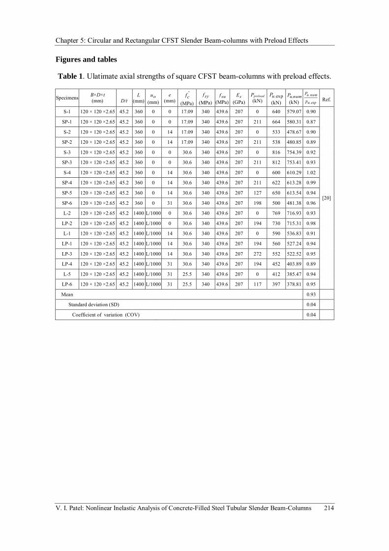
Chapter 5: Circular and Rectangular CFST Slender Beam-columns with Preload Effects
V. I. Patel: Nonlinear Inelastic Analysis of Concrete-Filled Steel Tubular Slender Beam-Columns 214
Figures and tables
Table 1. Ulatimate axial strengths of square CFST beam-columns with preload effects.
Specimens B×D×t (mm)
D/t
L (mm)
ou
(mm) e
(mm) '
cf (MPa)
syf
(MPa) suf
(MPa) sE
(GPa) Ppreload (kN)
exp.uP
(kN) numuP .
(kN) exp.u
num.upP Ref.
S-1 120 × 120 ×2.65 45.2 360 0 0 17.09 340 439.6 207 0 640 579.07 0.90
[20]
SP-1 120 × 120 ×2.65 45.2 360 0 0 17.09 340 439.6 207 211 664 580.31 0.87
S-2 120 × 120 ×2.65 45.2 360 0 14 17.09 340 439.6 207 0 533 478.67 0.90
SP-2 120 × 120 ×2.65 45.2 360 0 14 17.09 340 439.6 207 211 538 480.85 0.89
S-3 120 × 120 ×2.65 45.2 360 0 0 30.6 340 439.6 207 0 816 754.39 0.92
SP-3 120 × 120 ×2.65 45.2 360 0 0 30.6 340 439.6 207 211 812 753.41 0.93
S-4 120 × 120 ×2.65 45.2 360 0 14 30.6 340 439.6 207 0 600 610.29 1.02
SP-4 120 × 120 ×2.65 45.2 360 0 14 30.6 340 439.6 207 211 622 613.28 0.99
SP-5 120 × 120 ×2.65 45.2 360 0 14 30.6 340 439.6 207 127 650 613.54 0.94
SP-6 120 × 120 ×2.65 45.2 360 0 31 30.6 340 439.6 207 198 500 481.38 0.96
L-2 120 × 120 ×2.65 45.2 1400 L/1000 0 30.6 340 439.6 207 0 769 716.93 0.93
LP-2 120 × 120 ×2.65 45.2 1400 L/1000 0 30.6 340 439.6 207 194 730 715.31 0.98
L-1 120 × 120 ×2.65 45.2 1400 L/1000 14 30.6 340 439.6 207 0 590 536.83 0.91
LP-1 120 × 120 ×2.65 45.2 1400 L/1000 14 30.6 340 439.6 207 194 560 527.24 0.94
LP-3 120 × 120 ×2.65 45.2 1400 L/1000 14 30.6 340 439.6 207 272 552 522.52 0.95
LP-4 120 × 120 ×2.65 45.2 1400 L/1000 31 30.6 340 439.6 207 194 452 403.89 0.89
L-5 120 × 120 ×2.65 45.2 1400 L/1000 31 25.5 340 439.6 207 0 412 385.47 0.94
LP-6 120 × 120 ×2.65 45.2 1400 L/1000 31 25.5 340 439.6 207 117 397 378.81 0.95
Mean 0.93
Standard deviation (SD) 0.04
Coefficient of variation (COV) 0.04

Chapter 5: Circular and Rectangular CFST Slender Beam-columns with Preload Effects
V. I. Patel: Nonlinear Inelastic Analysis of Concrete-Filled Steel Tubular Slender Beam-Columns 215
Fig. 1. Fiber strain distribution in CFST beam-column section under axial load and biaxial bending.
Fig. 2. Stress-strain curve for concrete in rectangular CFST columns.
Concrete fibers
D
B
N.A.
Pn
x
y
dn
de,i
t
i
yi
yn,i
Steel fibers
t
C D
A B
c0.0150.005 cctc
'
fct
tu
fcc'
c fcc'
c
o

Chapter 5: Circular and Rectangular CFST Slender Beam-columns with Preload Effects
V. I. Patel: Nonlinear Inelastic Analysis of Concrete-Filled Steel Tubular Slender Beam-Columns 216
Fig. 3. Stress-strain curves for structural steels.
Fig. 4. Effective and ineffective areas of steel tubular cross-section under axial load and biaxial bending.
esu 0
fsu
fsy
0.9fsy
ss
0.9esy est es
D x
y
b
b
Pn
e1
e2
1
2
t
N.A.
Effective steel area Ineffective steel area
b
B
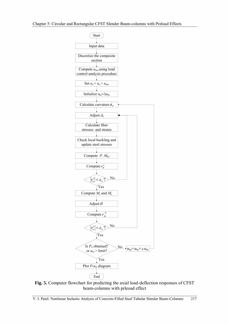
Chapter 5: Circular and Rectangular CFST Slender Beam-columns with Preload Effects
V. I. Patel: Nonlinear Inelastic Analysis of Concrete-Filled Steel Tubular Slender Beam-Columns 217
Fig. 5. Computer flowchart for predicting the axial load-deflection responses of CFST
beam-columns with prleoad effect
Start
Discretize the composite section
Initialize um=∆um
Calculate curvature
Adjust dn
Calculate fiber stresses and strains
Compute P, Mmi
Check local buckling and update steel stresses
Plot P-um diagram
um=um+∆ umIs Pn obtained?or um > limit?
End
Input data
Yes
Yes
No
No
m
Compute Mx and My
Adjust
No
Yes
Compute bmr
?kb
mr
Compute amr
?ka
mr
Compute umo using load control analysis procedure
Set uo = uo + umo

Chapter 5: Slender Beam-Columns with Preload Effects
V. I. Patel: Nonlinear Inelastic Analysis of Concrete-Filled Steel Tubular Slender Beam-Columns 218
Fig. 6. Comparison of computational and experimental axial load-deflection curves for specimen LP-1.
Fig. 7. Comparison of predicted and experimental axial load-deflection curves for specimen LP-6.
0
100
200
300
400
500
600
0 5 10 15 20 25 30 35
Axi
al lo
ad (k
N)
Mid-height deflection um (mm)
Experiment (LP-1)
Numerical analysis
0
50
100
150
200
250
300
350
400
450
0 5 10 15 20 25 30 35
Axi
al lo
ad (k
N)
Mid-height deflection um (mm)
Experiment (LP-6)
Numerical analysis

Chapter 5: Slender Beam-Columns with Preload Effects
V. I. Patel: Nonlinear Inelastic Analysis of Concrete-Filled Steel Tubular Slender Beam-Columns 219
Fig. 8. Effects of local buckling on the axial load-deflection curves for CFST slender beam-column 3.0a .
Fig. 9. Effects of local buckling on the strength envelopes for CFST slender beam-column 3.0a .
0
2000
4000
6000
8000
10000
12000
0 30 60 90 120 150
Axi
al lo
ad (k
N)
Mid-height deflection um (mm)
Local buckling ignored
Local buckling considered
0
0.2
0.4
0.6
0.8
1
1.2
0 0.2 0.4 0.6 0.8 1 1.2
Axi
al lo
ad P
n/Poa
Moment Mn/Mo
Local buckling ignored
Local buckling considered

Chapter 5: Slender Beam-Columns with Preload Effects
V. I. Patel: Nonlinear Inelastic Analysis of Concrete-Filled Steel Tubular Slender Beam-Columns 220
Fig. 10. Effects of preloads on the axial load-deflection curves for CFST beam-columns.
Fig. 11. Effects of preloads on the strength envelopes for CFST slender beam-column.
ba=0.8
ba=0ba=0.4
0
2000
4000
6000
8000
10000
12000
14000
16000
18000
0 100 200 300 400 500
Axi
al lo
ad (k
N)
Mid-height deflection um (mm)
0
0.2
0.4
0.6
0.8
1
1.2
0 0.2 0.4 0.6 0.8 1 1.2
Axi
al lo
ad P
n/Pop
Moment Mn/Mo
Preload effect ignored
Preload effect considered

Chapter 5: Slender Beam-Columns with Preload Effects
V. I. Patel: Nonlinear Inelastic Analysis of Concrete-Filled Steel Tubular Slender Beam-Columns 221
Fig. 12. Effects of preloads and diameter-to-thickness ratio on the ultimate axial strengths.
Fig. 13. Strength reduction caused by preloads in CFST beam-column with various depth-to-thickness ratios.
ba=0
ba=0.3
ba=0.6
0
5000
10000
15000
20000
25000
30000
35000
40000
0 10 20 30 40 50 60
Axi
al lo
ad (k
N)
Depth-to-thickness ratio D/t
ba=0.3
ba=0.6
0
2
4
6
8
10
12
14
0 10 20 30 40 50 60
Stre
ngth
redu
ction
(%)
Depth-to-thickness ratio D/t

Chapter 5: Slender Beam-Columns with Preload Effects
V. I. Patel: Nonlinear Inelastic Analysis of Concrete-Filled Steel Tubular Slender Beam-Columns 222
Fig. 14. Effects of preloads on the column strength curves.
Fig. 15. Strength reduction caused by preloads in CFST beam-columns with various slenderness ratios.
ba=0
ba=0.3
ba=0.6
0
0.1
0.2
0.3
0.4
0.5
0.6
0.7
0.8
0 20 40 60 80 100 120
Ulti
mat
e axi
al lo
ad P
n/P
o
Slenderness ratio L/r
ba=0.3
ba=0.6
0
2
4
6
8
10
12
14
16
18
20
0 20 40 60 80 100 120
Stre
ngt
h r
edu
ctio
n (%
)
Slenderness ratio L/r

Chapter 5: Slender Beam-Columns with Preload Effects
V. I. Patel: Nonlinear Inelastic Analysis of Concrete-Filled Steel Tubular Slender Beam-Columns 223
Fig. 16. Effects of preloads and loading eccentricity ratio on the ultimate axial strength.
Fig. 17. Strength reduction caused by preloads in CFST beam-columns with various loading eccentricity ratios.
ba=0
ba=0.3
ba=0.6
0
0.1
0.2
0.3
0.4
0.5
0.6
0.7
0.8
0 0.2 0.4 0.6 0.8 1 1.2 1.4 1.6 1.8 2 2.2
Ulti
mat
e axi
al lo
ad P
n/P
o
Eccentricity ratio e/D
ba=0.3
ba=0.6
0
1
2
3
4
5
6
7
8
9
10
0 0.2 0.4 0.6 0.8 1 1.2 1.4 1.6 1.8 2 2.2
Stre
ngth
redu
ction
(%)
Eccentricity ratio e/D

Chapter 5: Slender Beam-Columns with Preload Effects
V. I. Patel: Nonlinear Inelastic Analysis of Concrete-Filled Steel Tubular Slender Beam-Columns 224
Fig. 18. Effects of preloads and steel yield strengths on the ultimate axial strength.
Fig. 19. Strength reduction caused by preloads in CFST beam-columns with various steel yield strengths.
ba=0ba=0.3ba=0.6
0
0.05
0.1
0.15
0.2
0.25
0.3
0.35
0.4
0 100 200 300 400 500 600 700 800 900
Ulti
mat
e axi
al lo
ad P
n/P
o
Steel yield strength fsy (MPa)
ba=0.3
ba=0.6
0
2
4
6
8
10
12
14
0 100 200 300 400 500 600 700 800
Stre
ngth
redu
ction
(%)
Steel yield strength fsy (MPa)
Chapter 5: Slender Beam-Columns with Preload Effects
V. I. Patel: Nonlinear Inelastic Analysis of Concrete-Filled Steel Tubular Slender Beam-Columns 225
5.5 CONCLUDING REMARKS
Numerical models for simulating the behavior of eccentrically loaded circular and
rectangular CFST slender beam-columns with preload effects have been developed in
this chapter. The effects of preloads, local buckling, concrete confinement, initial
geometric imperfections and second order have been considered in the numerical
models. The inelastic behavior of composite cross-sections with local buckling effects is
modeled using the accurate fiber element method. Deflections caused by preloads on the
steel tubes are incorporated in the inelastic stability analysis of CFST slender beam-
columns as additional geometric imperfections. Computational procedures have been
developed for simulating the load-deflection responses of CFST slender beam-columns
under axial load and bending. The accuracy of the numerical models developed has
been established by comparisons of computer solutions with existing experimental
results. The numerical models were used to investigate the effects of the preload ratio,
depth-to-thickness ratio, column slenderness and loading eccentricity on the behavior of
thin-walled CFST slender beam-column under axial load and bending.

Chapter 6: Rectangular CFST slender Beam-Columns under Cyclic Loading
V. I. Patel: Nonlinear Inelastic Analysis of Concrete-Filled Steel Tubular Slender Beam-Columns 226
Chapter 6
RECTANGULAR CFST SLENDER BEAM-
COLUMNS UNDER CYCLIC LOADING
6.1 INTRODUCTION
This chapter presents a numerical model for simulating the cyclic behavior of high
strength thin-walled rectangular CFST slender beam-columns with cyclic local buckling
effects. Uniaxial cyclic stress-strain relationships for the concrete core and structural
steels are incorporated in the numerical model. The effects of initial geometric
imperfections, high strength materials and second order are also taken into account in
the numerical model for CFST slender beam-columns under constant axial load and
cyclically varying lateral loading. Müller’s method algorithms are developed and
implemented in the numerical model to iterate the neutral axis depth in a thin-walled
CFST beam-column section. The ultimate lateral loads and cyclic load-deflection curves
for thin-walled CFST beam-columns predicted by the numerical model are verified by

Chapter 6: Rectangular CFST slender Beam-Columns under Cyclic Loading
V. I. Patel: Nonlinear Inelastic Analysis of Concrete-Filled Steel Tubular Slender Beam-Columns 227
experimental data. The numerical model is then utilized to investigate the effects of
cyclic local buckling, column slenderness ratio, depth-to-thickness ratio, concrete
compressive strengths and steel yield strengths on the cyclic load-deflection responses
of CFST slender beam-columns.
This chapter includes the following paper:
[1] Patel, V. I., Liang, Q. Q. and Hadi, M. N. S., “Numerical analysis of high-strength
concrete-filled steel tubular slender beam-columns under cyclic loading”, Journal
of Constructional Steel Research, 2013 (submitted).

228

229

Chapter 6: Rectangular CFST slender Beam-Columns under Cyclic Loading
V. I. Patel: Nonlinear Inelastic Analysis of Concrete-Filled Steel Tubular Slender Beam-Columns 230
Manuscript prepared for
Journal of Constructional Steel Research
January 2013
Numerical Analysis of High-Strength Concrete-Filled Steel
Tubular Slender Beam-Columns under Cyclic Loading
Vipulkumar Ishvarbhai Patela, Qing Quan Liang
a,*, Muhammad N. S. Hadi
b
aCollege of Engineering and Science, Victoria University, PO Box 14428, Melbourne, VIC 8001, Australia
bSchool of Civil, Mining and Environmental Engineering, University of Wollongong,
Wollongong, NSW 2522, Australia
Corresponding author:
Associate Professor Qing Quan Liang College of Engineering and Science Victoria University PO Box 14428 Melbourne VIC 8001 Australia Phone: +61 3 9919 4134 E-mail: [email protected]

Chapter 6: Rectangular CFST slender Beam-Columns under Cyclic Loading
V. I. Patel: Nonlinear Inelastic Analysis of Concrete-Filled Steel Tubular Slender Beam-Columns 231
Numerical analysis of high-strength concrete-filled steel tubular slender beam-columns under cyclic loading
Vipulkumar Ishvarbhai Patela, Qing Quan Lianga,, Muhammad N. S. Hadib
a College of Engineering and Science, Victoria University, PO Box 14428, Melbourne,
VIC 8001, Australia b School of Civil, Mining and Environmental Engineering, University of Wollongong,
Wollongong, NSW 2522, Australia
ABSTRACT
The effects of cyclic local buckling on the cyclic behavior of concrete-filled steel
tubular (CFST) slender beam-columns were approximately considered in existing
analytical models by modifying the stress-strain curve for the steel tube in compression.
This modified stress-strain curve method, however, cannot simulate the progressive
cyclic local and post-local buckling of the steel tubes. This paper presents a new
numerical model for predicting the cyclic performance of high strength thin-walled
rectangular CFST slender beam-columns accounting for the effects of progressive cyclic
local and post-local buckling of steel tube walls under stress gradients. Uniaxial cyclic
constitutive laws for the concrete core and steel tubes are incorporated in the fiber
element formulation of the model. The effects of initial geometric imperfections, high
strength materials and second order are also included in the nonlinear analysis of CFST
slender beam-columns under constant axial load and cyclically varying lateral loading.
Corresponding author. Tel.: 61 3 9919 4134. E-mail address: [email protected] (Q. Q. Liang)

Chapter 6: Rectangular CFST slender Beam-Columns under Cyclic Loading
V. I. Patel: Nonlinear Inelastic Analysis of Concrete-Filled Steel Tubular Slender Beam-Columns 232
The Müller’s method is adopted to solve nonlinear equilibrium equations. The accuracy
of the numerical model is examined by comparisons of computer solutions with
experimental results. A parametric study is conducted to investigate the effects of cyclic
local buckling, column slenderness ratio, depth-to-thickness ratio, concrete compressive
strength and steel yield strength on the cyclic responses of CFST slender beam-
columns. It is shown that the numerical model predicts well the experimentally
observed cyclic lateral load-deflection characteristics of CFST slender beam-columns.
The numerical results presented reflect the cyclic local and global buckling behavior of
high strength rectangular CFST slender beam-columns, which have not been reported in
the literature.
Keywords: Concrete-filled steel tubes; Cyclic loading; High strength; Local and post-
local buckling; Nonlinear analysis; Slender beam-columns.
1. Introduction
High strength thin-walled rectangular CFST slender beam-columns have increasingly
been used in composite buildings and bridges in seismic regions due to their high
structural performance such as high strength, high stiffness, high ductility and large
energy absorption capacity. In seismic regions, thin-walled CFST slender beam-
columns may be subjected to a constant axial load from upper floors and cyclically
varying lateral loading due to the earthquake. These cyclically loaded beam-columns
may undergo cyclic local and global interaction buckling, which makes the predictions
of their cyclic performance highly complicated. Cyclic local buckling reduces the

Chapter 6: Rectangular CFST slender Beam-Columns under Cyclic Loading
V. I. Patel: Nonlinear Inelastic Analysis of Concrete-Filled Steel Tubular Slender Beam-Columns 233
strength and ductility of thin-walled CFST slender beam-columns. It is therefore
important to incorporate cyclic local buckling effects in nonlinear analysis techniques so
that the cyclic performance of thin-walled CFST slender beam-columns under cyclic
loading can be accurately predicted.
Experimental studies on the ultimate strengths of CFST columns under monotonic axial
load or combined monotonic axial load and bending have been very extensive in the
past [1-12]. However, only limited tests have been conducted on CFST beam-columns
under cyclic loading. Experiments on square CFST beam-columns under axial load and
cyclic lateral loading were performed by Varma et al. [13,14]. These test specimens
were made of high strength concrete of 110 MPa and steel tube with yield stress ranging
from 269 MPa to 660 MPa. Their studies indicated that the cracking of the infilled
concrete and local buckling of the steel tubes reduced the flexural stiffness of CFST
beam-columns. Han et al. [15] investigated experimentally the effects of the depth-to-
thickness ratio, concrete compressive strength and axial load level on the cyclic
behavior of square and rectangular CFST beam-columns. They reported that local
buckling of CFST beam-columns occurred after the steel yielded. Tests on normal
strength square CFST beam-columns under cyclic loading were undertaken by Wu et al.
[16]. It was observed that the steel tube walls buckled outward after the concrete was
damaged.
Various nonlinear analysis techniques for predicting the cyclic responses of CFST
beam-columns have been reported in the literature. Varma et al. [13] developed a fiber
element model for rectangular CFST beam-columns under cyclic loading. The uniaxial

Chapter 6: Rectangular CFST slender Beam-Columns under Cyclic Loading
V. I. Patel: Nonlinear Inelastic Analysis of Concrete-Filled Steel Tubular Slender Beam-Columns 234
cyclic stress-strain relationships for steel and concrete were derived from the nonlinear
finite element analyses of CFST beam-columns. The stress-strain curve for steel in
compression was modified to approximately account for the effects of local buckling.
Gayathri et al. [17,18] proposed an efficient fiber element technique for the nonlinear
analysis of CFST short and slender beam-columns under monotonic and cyclic loading.
Their technique was formulated for normal strength CFST beam-columns where local
buckling effects were not included. Chung et al. [19] presented a fiber element model
for the analysis of cyclically loaded square CFST beam-columns. The effect of local
buckling was approximately taken into account in the model by modifying the stress-
strain curve for steel in compression. However, their model did not consider concrete
tensile strength and high strength materials. Zubydan and ElSabbagh [20] proposed a
mathematical model for the nonlinear analysis of normal strength rectangular CFST
beam-columns where local buckling was approximately considered by modifying the
stress-strain curve for steel in compression. The fiber element model presented by Wu et
al. [16] could be used to analyze normal strength square CFST beam-columns,
providing that the steel sections are compact. It should be noted that the modified stress-
strain curve method used in the above mentioned models might overestimate or
underestimate the cyclic local buckling strengths of steel tubes under stress gradients.
This is because they cannot model the progressive cyclic local buckling of the steel tube
from the onset to the post-local buckling, which is characterized by stress redistributions
within the buckled tube wall.
The local buckling problem of thin-walled CFST columns has been studied
experimentally by various researchers [21-24]. Liang et al. [25] proposed a fiber

Chapter 6: Rectangular CFST slender Beam-Columns under Cyclic Loading
V. I. Patel: Nonlinear Inelastic Analysis of Concrete-Filled Steel Tubular Slender Beam-Columns 235
element model for the nonlinear analysis of thin-walled CFST short columns under axial
compression, accounting for progressive local buckling effects by using effective width
formulas. Liang [26,27] developed a numerical model for simulating the axial load-
strain responses, moment-curvature relationships and axial load-moment interaction
diagrams of high strength rectangular CFST short beam-columns under axial load and
biaxial bending. The effects of local buckling of steel tube walls under stress gradients
were incorporated in the model by using initial local buckling equations and effective
width formulas proposed by Liang et al [28]. Patel et al.[29,30] and Liang et al. [31]
extended the numerical models developed by Liang et al. [25] and Liang [26,27] to the
nonlinear analysis of eccentrically loaded high strength thin-walled rectangular CFST
slender beam-columns considering the effects of local buckling, geometric
imperfections, second order and high strength materials.
The above literature review indicates that there is relatively little numerical study on the
fundamental behavior of cyclically loaded high strength rectangular CFST slender
beam-columns with large depth-to-thickness ratios. In this paper, a numerical model is
developed to simulate the cyclic performance of high strength thin-walled rectangular
CFST slender beam-columns incorporating cyclic local buckling effects. Comparative
study is undertaken to verify the numerical model. The fundamental cyclic behavior of
CFST slender beam-columns under constant axial load and cyclically varying lateral
loading is investigated using the computer program developed and the results obtained
are discussed.
2. Material constitutive models

Chapter 6: Rectangular CFST slender Beam-Columns under Cyclic Loading
V. I. Patel: Nonlinear Inelastic Analysis of Concrete-Filled Steel Tubular Slender Beam-Columns 236
2.1 Cyclic constitutive models for concrete
The confinement provided by the steel tube increases only the ductility of the concrete
core in a rectangular CFST column but not its strength. This confinement effect is
considered in the cyclic stress-strain curves schematically depicted in Fig. 1. The cyclic
stress-strain relationships account for the effects of stiffness degradation and crack
opening and closing characteristics of concrete under cyclic loading. The envelope
curve for the concrete under cyclic axial compression can be characterized by the
monotonic stress-strain curve of the concrete, which is divided into ascending, constant,
linearly descending and constant parts as shown in Fig. 1. The longitudinal compressive
concrete stress for the ascending part from O to A is calculated based on the equation
given by Mander et al. [32] as:
'cc
c
'cc
c'cc
c
f
1
(1)
'cc
'cc
c
c
fE
E
(2)
where 'ccf is the effective compressive strength of concrete, c is the longitudinal
compressive strain of concrete, 'cc is the strain at '
ccf and cE is the Young’s modulus of
concrete which is given by ACI 318-11 [33] as

Chapter 6: Rectangular CFST slender Beam-Columns under Cyclic Loading
V. I. Patel: Nonlinear Inelastic Analysis of Concrete-Filled Steel Tubular Slender Beam-Columns 237
(MPa)69003320 ' ccc fE (3)
The effective compressive strengths of concrete 'ccf is taken as '
cc f , where c is the
strength reduction factor proposed by Liang [26] to account for the column size effects
and expressed as
01850851 1350 ..D. c.
cc (4)
in which cD is taken as the larger of tB 2 and tD 2 for a rectangular cross-
section, where B is the width of the cross-section, D is the depth of the cross-section,
and t is the thickness of the steel tube wall.
In the numerical model, the strain 'cc corresponding to '
ccf is taken as 0.002 for the
effective compressive strength less than or equal to 28 MPa and 0.003 for MPa82'ccf .
For the effective compressive strength between 28 and 82 MPa, the strain 'cc is
determined by the linear interpolation.
The parts AB, BC and CD of the stress-strain curve for concrete in CFST columns as
shown in Fig. 1 are defined by the following equations given by Liang [26]:
0150for
01500.005for0150100
0050for
c
c
.f.ff.f
.f
'ccc
'ccc
'ccc
'ccc
c'cc
'cc
c
(5)

Chapter 6: Rectangular CFST slender Beam-Columns under Cyclic Loading
V. I. Patel: Nonlinear Inelastic Analysis of Concrete-Filled Steel Tubular Slender Beam-Columns 238
where c was proposed by Liang [26] based on experimental results presented by Tomii
and Sakino [34] as follows:
48for50
4824for48151
24for01
tB.
tB
tB.
tB.
s
ss
s
c (6)
in which sB is taken as the larger of B and D for a rectangular cross-section.
The concrete under compression is initially loaded up to an unloading strain and then
unloaded to a zero stress level. The reloading of the concrete from the zero stress up to
the envelope curve is characterized by the linear stress-strain relationships. For the
unloading of concrete, the parabolic curve of the concrete is defined by the following
equations [32]:
uncpl
unpl
uncu
unpl
uncuun
unc u
ff
1
(7)
plun
unu
uu
fE
E
(8)
where unf is the compressive stress of concrete at the unloading, un is the strain at unf ,
pl is the plastic strain which is proposed by Mander et al. [32] as:

Chapter 6: Rectangular CFST slender Beam-Columns under Cyclic Loading
V. I. Patel: Nonlinear Inelastic Analysis of Concrete-Filled Steel Tubular Slender Beam-Columns 239
acun
aununununpl Ef
ff
(9)
in which a is given as
'ccuna a (10)
where a is taken as the larger of un'cc
'cc and ccun. 090 for a rectangular cross-
section.
In Eq. (8), uE is the initial modulus of elasticity at the unloading proposed by Mander et
al. [32] and is expressed by:
cun
cc
cc
unu E
ffE
'
' (11)
in which ,0.1/ ' ccun ff and 0.1/' uncc .
For the reloading of concrete, a linear stress-strain relationship is assumed as follows:
rocplrorocrc fE (12)
where rE is given by

Chapter 6: Rectangular CFST slender Beam-Columns under Cyclic Loading
V. I. Patel: Nonlinear Inelastic Analysis of Concrete-Filled Steel Tubular Slender Beam-Columns 240
rero
reror
ffE
(13)
in which rof is the concrete stress at the reloading, ro is the strain at rof , and re and
ref are the return strain and stress on the monotonic curve as shown in Fig. 1.
The envelop stress-strain curve for concrete under tension is divided into the linear
descending and ascending parts as shown in Fig. 1. The concrete tensile stress linearly
increases with the tensile strain of concrete up to concrete cracking. After concrete
cracking, the tensile stress of concrete is inversely proportional to the tensile strain of
concrete up to the ultimate tensile strain. The tensile strength of concrete is taken as
'ccf.60 . The concrete tensile stress is considered zero at the ultimate tensile strain. The
ultimate tensile strain is taken as 10 times of the strain at cracking.
For unloading from a compressive envelope curve, the stress in the concrete fiber under
tension can be given by:
plc'ct'
ct
plc'
ct
'ctc
'tu'
tu'ct
plc'
ct
t f
f
for
for (14)
in which
Chapter 6: Rectangular CFST slender Beam-Columns under Cyclic Loading
V. I. Patel: Nonlinear Inelastic Analysis of Concrete-Filled Steel Tubular Slender Beam-Columns 241
'
cc
plct
'ct ff
1 (15)
plctct ' (16)
For unloading from a tensile envelope curve, the reloading the concrete cannot carry the
load up to the tensile strength so that the reloading branch follows the unloading branch.
2.2. Cyclic constitutive models for structural steels
The cyclic stress-strain relationship for the structural steels is shown in Fig. 2. The mild
structural steels have a linear stress-strain relationship up to syf.90 , where syf is the
steel yield strength. The parabolic curve for cold-formed structural steels can be defined
by the equation proposed by Liang [26]. The parabolic curve is replaced by the straight
line for high strength steels. The hardening strain st is assumed to be 0.005 for high
strength and cold-formed steels and 10 sy for mild structural steels in the numerical
model. The ultimate strain of steels is taken as 0.2.
For the cyclic stress-strain curve, the unloading follows a straight line with the same
slope as the initial stiffness as shown in Fig. 2. The unloading part of the structural
steels can be defined by the following equation:
mosomosss E (17)

Chapter 6: Rectangular CFST slender Beam-Columns under Cyclic Loading
V. I. Patel: Nonlinear Inelastic Analysis of Concrete-Filled Steel Tubular Slender Beam-Columns 242
where s is the stress in a steel fiber, sE is the Young’s modulus of steel, s is the
strain in the steel fiber and mo is given by:
s
oomo E
f (18)
in which o is the strain at the unloading, of is the stress at the unloading.
The reloading curve for steels is described by the equations given by Shi et al. [35] as:
bsmoosksmosss EEE (19)
mob
bkE
(20)
where is proposed by Shi et al. [35] as:
04.0for08.0
08.0074.1
04.0for05.0
05.0048.1
b o
ob
os
ob
ob
os
(21)
For the reloading, the initial value of the strain b is taken as sy. 90 . The stress bf at
the strain b can be determined from the monotonic stress-strain curves. For the strain

Chapter 6: Rectangular CFST slender Beam-Columns under Cyclic Loading
V. I. Patel: Nonlinear Inelastic Analysis of Concrete-Filled Steel Tubular Slender Beam-Columns 243
greater than the strain b , the cyclic skeleton curve is used to predict the stress in the
steel fiber. After initial reloading, the reloading is directed toward the previous
unloading.
3. Modeling of cross-sectional strengths
3.1. Strain calculations
The behavior of composite cross-sections is modeled using the accurate fiber element
method. The cross-section is divided into fiber elements as shown in Fig. 3. Each fiber
element can be assigned with either steel or concrete material properties. Fiber element
stresses are calculated from fiber strains using cyclic stress-strain relationships. The
strain t at the top fiber of the cross-section can be determined by multiplication of the
curvature and the neutral axis depth nd . For bending about the x-axis, strains in
concrete and steel fibers can be calculated by the following equations proposed by
Liang [26]:
ni,n dDy 2
(22)
i,nii,e yyd (23)
i,nii,e
i,nii,ei yyd
yydforfor
(24)

Chapter 6: Rectangular CFST slender Beam-Columns under Cyclic Loading
V. I. Patel: Nonlinear Inelastic Analysis of Concrete-Filled Steel Tubular Slender Beam-Columns 244
in which nd is the neutral axis depth, i,ed is the orthogonal distance from the centroid
of each fiber element to the neutral axis, iy is the coordinates of the fiber i and i is
the strain at the thi fiber element.
3.2. Initial local buckling of steel tube walls under stress gradients
The steel tube walls of a CFST column are restrained by the concrete core so that they
can only buckle outward. The edges of the tube wall can be assumed as clamped. Liang
et al. [28] developed nonlinear finite element models to study the local and post-local
buckling behavior of clamped steel plates that form a CFST column under stress
gradients. The models accounted for geometric imperfection of t1.0 at the plate centre
and compressive residual stresses of syf25.0 , which were balanced by the tensile
residual stresses locked in the same plate. Based on the finite element results, Liang et
al. [28] proposed a set of formulas for determining the initial local buckling stress of
steel tube walls subjected to compressive stress gradients. These formulas are
incorporated in the numerical model to determine the onset of cyclic local buckling of
thin-walled CFST slender beam-columns.
3.3. Post-local buckling of steel tube walls under stress gradients
The effective width concept is usually used to determine the post-local buckling
strengths of thin steel plates. Liang et al. [28] proposed a set of effective width formulas
for steel tube walls of CFST columns under compressive stress gradients. The effective
width is a function of the width-to-thickness ratio )( tb and compressive stress gradient

Chapter 6: Rectangular CFST slender Beam-Columns under Cyclic Loading
V. I. Patel: Nonlinear Inelastic Analysis of Concrete-Filled Steel Tubular Slender Beam-Columns 245
)( s . Their formulas are incorporated in the numerical model to determine the ultimate
strengths of steel tube walls subjected to stress gradients. Fig. 3 shows the effective and
ineffective areas of a steel cross-section under axial load and uniaxial bending. The
effective widths 1eb and 2eb of a steel tube wall under stress gradients are given by
Liang et al. [28] as
0for106854103555002047041860
00for10605910972101019027770
s
37
25
s
37
24
1
tb.
tb.
tb..
.tb.
tb.
tb..
bbe (25)
b
bb
b es
e 12 2 (26)
where b is the clear width of a steel flange or web in the section, and 12 s , 1 is
the maximum edge stress acting on the steel tube wall and 2 is the minimum edge
stress acting on the same steel tube wall. It is noted that the effective width formulas
were proposed for clamped steel plates with b/t ratio ranging from 30 to 100. For a plate
with a b/t ratio less than 30, the plate is treated as compact.
The post-local buckling of a thin steel plate is characterized by the gradual
redistribution of stresses within the buckled plate. After the onset of local buckling, the
ineffective width of the plate increases with increasing the compressive load until the
plate attains its ultimate strength, which is governed by the effective widths given by
Eqs. (25) and (26). In the present study, the progressive post-local buckling of steel tube
walls under stress gradients is modeled by gradually redistributing the normal stresses

Chapter 6: Rectangular CFST slender Beam-Columns under Cyclic Loading
V. I. Patel: Nonlinear Inelastic Analysis of Concrete-Filled Steel Tubular Slender Beam-Columns 246
within the steel tube wall. This can be done by assigning the steel fiber elements located
in the ineffective areas to zero stress (Liang 26).
3.4. Stress resultants
The internal axial force and bending moment carried by a composite cross-section under
axial load and uniaxial bending are determined as the stress resultants, which are
expressed by:
ns
i
nc
jjcjcisisn AAP
1 1,,,, (27)
ns
i
nc
jjj,cj,cii,si,sx yAyAM
1 1 (28)
where nP is the internal axial force, xM is the internal bending moment about the x-axis,
i,s is the longitudinal stress at the centroid of steel fiber i , i,sA is the area of steel fiber
i , j,c is the longitudinal stress at the centroid of concrete fiber j , j,cA is the area of
concrete fiber j , iy is the coordinates of steel element i , jy is the coordinates of
concrete element j , ns is the total number of steel fiber elements and nc is the total
number of concrete fiber elements.
3.5. The Müller’s method

Chapter 6: Rectangular CFST slender Beam-Columns under Cyclic Loading
V. I. Patel: Nonlinear Inelastic Analysis of Concrete-Filled Steel Tubular Slender Beam-Columns 247
The Müller’s method [36] is an efficient numerical technique for solving nonlinear
equilibrium equations. It is a generalization of the secant method, which has been used
to obtain nonlinear solutions to CFST short beam-columns under axial load and biaxial
bending by Liang [26]. Computational algorithms based on the Müller’s method are
developed to iterate the neutral axis depth in a rectangular CFST cross-section. The
Müller’s method requires three initial values of the neutral axis depth 1,nd , 2,nd and 3,nd .
The corresponding residual forces 1,pr , 2,pr and 3,pr are calculated based on the three
initial values of the neutral axis depth. The new neutral axis depth 4,nd is determined by
the following equations:
mmmm
m,n,n
cabbcdd
42
234
(29)
3,1,3,2,2,1,
3,2,3,1,3,1,3,2,
nnnnnn
ppnnppnnm dddddd
rrddrrdda
(30)
3,1,3,2,2,1,
3,1,2
3,2,3,2,2
3,1,
nnnnnn
ppnnppnnm dddddd
rrddrrddb
(31)
3,pm rc (32)
The values of the neutral axis depth 1,nd , 2,nd and 3,nd and corresponding residual
forces 1,pr , 2,pr and 3,pr need to be exchanged as discussed by Patel et al. [29]. Eq. (29)
and the exchange of the neutral axis depths and residual forces are iteratively executed
until the convergence criteria of kpr is satisfied. The sign of the square toot term in
the denominator of Eq. (29) is taken as the same sign of mb .

Chapter 6: Rectangular CFST slender Beam-Columns under Cyclic Loading
V. I. Patel: Nonlinear Inelastic Analysis of Concrete-Filled Steel Tubular Slender Beam-Columns 248
4. Modeling of cyclic load-deflection responses
4.1. Formulation
A cantilever column under a constant axial load P and cyclically varying lateral
loading F is considered in the numerical model. The deflected shape and coordinate
system for the cantilever column are depicted in Fig. 4, where L represents the actual
length of the column and lu demotes the lateral deflection at the tip of the column. The
effective length of the cantilever column is taken as L2 . The deflected shape of the
cantilever column is assumed to be part of a sine wave which is described by the
following displacement function:
Luu l 2
zsin (33)
The curvature along the length of the cantilever column can be derived from Eq. (33) as
Lu
Lzu
l 2zsin
2
2
2
2 (34)
The curvature at the base of the cantilever column is given by
lb uL
2
2
(35)

Chapter 6: Rectangular CFST slender Beam-Columns under Cyclic Loading
V. I. Patel: Nonlinear Inelastic Analysis of Concrete-Filled Steel Tubular Slender Beam-Columns 249
The external moment at the base of the cantilever column can be determined as
lolme uuePFLM (36)
in which e is the eccentricity of the axial load and it is taken as zero for the pure axial
load in the present study, lou is the initial geometric imperfection at the tip of the
cantilever columns.
The column must satisfy the force and moment equilibrium conditions at its base as
follows:
0PPn (37)
0 xlol MuuePFL (38)
where xM is the internal bending moment of the cross-section at the column base.
The lateral load can be determined as:
L
uuePMF lolx (39)
4.2. Computational procedure

Chapter 6: Rectangular CFST slender Beam-Columns under Cyclic Loading
V. I. Patel: Nonlinear Inelastic Analysis of Concrete-Filled Steel Tubular Slender Beam-Columns 250
An incremental-iterative numerical scheme based on the displacement control method
was employed in the computational procedure to predict the cyclic load-deflection
responses of slender beam-columns. The lateral deflection at the tip of the beam-column
is initialized. The curvature b at the column base is calculated from the given lateral
deflection lu using Eq. (35). The neutral axis depth of the composite cross-section is
iteratively adjusted using the Müller’s method. The force and moment equilibriums are
maintained at the base of the cantilever column. The internal bending moment xM is
determined from axial force and curvature relationship. The cyclic lateral load F at the
tip of the cantilever column is calculated using Eq. (39). The lateral deflection at the tip
of the cantilever column is gradually increased up to the predefined unloading
deflection. After the unloading deflection, the lateral deflection is gradually decreased
up to the reloading level. Note that the stresses of the steel and concrete fiber elements
depend not only on the strain of the element, but also on the complete stress-strain
history. The stresses and strains of the fiber elements for each lateral deflection are
recorded in the numerical analysis. The process is repeated until the ultimate cyclic
lateral load is obtained or the deflection limit is reached. The main steps of the
computational procedure are given as follows:
(1) Input data.
(2) Discretize the composite cross-section into fiber elements.
(3) Initialize the first unloading deflection ulu
(4) Initialize the lateral deflection at the tip of the cantilever column ll uu .
(5) Calculate the curvature b at the base of the cantilever column.
(6) Set ll uu if lull uuu or lull uuu .

Chapter 6: Rectangular CFST slender Beam-Columns under Cyclic Loading
V. I. Patel: Nonlinear Inelastic Analysis of Concrete-Filled Steel Tubular Slender Beam-Columns 251
(7) Define the next unloading deflection ulu if 0 oldllastllastll uuuu and
lastll uu .
(8) Recall the unloading strains and stresses at the unloading deflection.
(9) Adjust the neutral axis depth nd using the Müller’s method.
(10) Calculate fiber strains and stresses using cyclic stress-strain relationships.
(11) Check cyclic local buckling and update steel fiber stresses.
(12) Calculate resultant force P considering local buckling effects.
(13) Compute the residual force PPr np .
(14) Repeat Steps (9)-(13) until kpr .
(15) Compute the internal bending moment xM .
(16) Calculate the cyclic lateral force F using Eq. (39).
(17) Record the deflection lastloldl uu and llastl uu
(18) Store the fiber strains and fiber stresses under the current deflection.
(19) Increase the deflection at the tip of the cantilever column by lll uuu .
(20) Repeat Steps (5)-(19) until the ultimate cyclic lateral load uF is obtained or the
deflection limit is reached.
(21) Plot the cyclic load-deflection curve.
The convergence tolerance k is taken as 410 in the numerical analysis.
5. Validation of the numerical model

Chapter 6: Rectangular CFST slender Beam-Columns under Cyclic Loading
V. I. Patel: Nonlinear Inelastic Analysis of Concrete-Filled Steel Tubular Slender Beam-Columns 252
The accuracy of the developed numerical model is evaluated by comparing the
numerical solutions with experimental results given by Verma et al. [14]. The ultimate
cyclic lateral loads and cyclic load-deflection curves for high strength thin-walled
square CFST beam-columns are considered in the verification of the numerical model
developed.
5.1. Ultimate cyclic lateral loads
The dimensions and material properties of high strength CFST beam-columns tested by
Varma et al. [14] are given in Table 1. In the table, exp.uF represents the experimental
ultimate cyclic lateral load and num.uF denotes the ultimate cyclic lateral load predicted
by the numerical model. Specimens were tested under rotating axial load and cyclic
loading using special clevises-pins supports. All specimens had a square cross-section
of 305 × 305 mm. The depth-to-thickness ratios tD ranged from 34 to 52 while the
length of the column was 1200 mm. The steel tube of the specimens was filled with
high strength concrete of 110 MPa. It should be noted that the concrete compressive
strength given in Table 1 is the cylinder compressive strength. The yield strengths syf
of the steel tube varied from 269 MPa to 660 MPa. The experimental axial load applied
to each specimen was employed in the numerical analysis. It can be observed from
Table 1 that the ultimate cyclic lateral loads predicted by the numerical model are in
good agreement with experimental results. The mean ultimate cyclic lateral load
predicted by the numerical model is 99% of the experimental value with a standard
deviation of 0.11 and a coefficient of variation of 0.11.

Chapter 6: Rectangular CFST slender Beam-Columns under Cyclic Loading
V. I. Patel: Nonlinear Inelastic Analysis of Concrete-Filled Steel Tubular Slender Beam-Columns 253
5.2. Cyclic load-deflection curves
Cyclic load-deflection curves provide useful information on the initial stiffness, ultimate
cyclic lateral load, unloading stiffness, reloading stiffness and post-peak behavior of
thin-walled CFST beam-columns. To examine the accuracy of the proposed numerical
model, cyclic load-deflection curves predicted by the numerical model are compared
with experimental results reported by Varma et al. [14] in Figs. 5-7.
The tD ratios of these columns ranged from 34 to 52. Therefore, the local buckling of
the steel tube wall under stress gradients was considered in the numerical model. It can
be seen from Figs. 5-7 that the numerical model predicts well the ultimate cyclic lateral
loads when compared to test results. The predicted ultimate cyclic lateral load for
specimen CBC-32-80-10 is 95% of the experimental value. Reasonable agreement
between computed and experimental cyclic load-deflection curves is achieved for
specimens CBC-48-80-10, CBC-48-80-20, CBC-32-46-20, CBC-48-46-10 and CBC-
48-46-20. The ratios of computed ultimate cyclic lateral load to experimental value for
specimens CBC-48-80-10, CBC-48-80-20, CBC-32-46-20, CBC-48-46-10 and CBC-
48-46-20 are 1.14, 1.06, 0.86, 1.07 and 1.07, respectively. The predicted post-peak
behavior of the cyclic load-deflection curves for specimens is in reasonable agreement
with experimental data. The unloading and reloading stiffness of the cyclic load-
deflection curves predicted by the numerical model slightly differ from experimental
ones. This is likely due to the uncertainty of the actual concrete stiffness and strength.
6. Parametric study
Chapter 6: Rectangular CFST slender Beam-Columns under Cyclic Loading
V. I. Patel: Nonlinear Inelastic Analysis of Concrete-Filled Steel Tubular Slender Beam-Columns 254
In the parametric study, the axial load was taken as 10% of the ultimate axial strength of
the column cross-section. The computer program developed by Liang et al. [25] was
used to determine the ultimate axial strengths of column cross-sections under axial
compression. In the present study, the initial geometric imperfection at the tip of the
beam-column was taken as 1000L . The Young’s modulus of steel material was 200
GPa. The yield stress of 690 MPa and the tensile strength of 790 MPa were assumed for
steel tubes, except where specially indicated. The effects of cyclic local and post-local
buckling were considered in all analyses. The typical cyclic loading pattern used in the
parametric study is illustrated in Fig. 8.
6.1. Effects of local buckling
The numerical model was employed to investigate the effects of cyclic local buckling
on the cyclic load-deflection curves for high strength CFST slender beam-columns
under constant axial load and cyclically varying lateral loading. A thin-walled CFST
beam-column with a cross-sectional dimension of 700 × 800 mm was considered. The
thickness of the steel tube was 8 mm so that its depth-to-thickness ratio tD was 100.
The compressive cylinder strength of concrete was 80 MPa. The column slenderness
ratio rLe was 22. The applied axial load was 4623.1 kN. Analyses of the beam-
column were carried out by considering and ignoring cyclic local buckling effects
respectively.

Chapter 6: Rectangular CFST slender Beam-Columns under Cyclic Loading
V. I. Patel: Nonlinear Inelastic Analysis of Concrete-Filled Steel Tubular Slender Beam-Columns 255
Fig. 9 shows the effects of cyclic local buckling on the cyclic load-deflection curves for
thin-walled CFST beam-columns. It can be seen from Fig. 9 that cyclic local buckling
considerably reduces the stiffness and ultimate cyclic lateral load of the slender beam-
column with the same axial load level. The ultimate cyclic lateral load of the slender
beam-column is overestimated by 4.3% if local buckling was not considered. More
reduction in the ultimate cyclic lateral load would be expected if higher axial load was
applied to the column. In addition, cyclic local buckling tends to reduce the ductility of
the column under cyclic loading, which is important for seismic design of composite
buildings. These highlight the importance of considering cyclic local buckling in the
analysis and design.
6.2. Effects of column slenderness ratio
The numerical model developed was used to examine the important effects of the
column slenderness ratio. High strength thin-walled CFST slender beam-columns with a
cross-section of 700 × 700 mm were considered. The depth-to-thickness ratio of the
section was 70. Column slenderness ratios rLe of 22 and 30 were considered in the
parametric study. The steel tubes were filled with high strength concrete of 70 MPa. The
axial load of 4131.2 kN was applied to the beam-column.
The cyclic load-deflection curves for high strength thin-walled CFST slender beam-
columns with rLe / ratios of 22 and 30 are presented respectively in Figs. 10(a) and
10(b). The ultimate lateral load of thin-walled CFST slender beam-columns tends to
decrease when increasing the column slenderness ratio of the beam-columns under the

Chapter 6: Rectangular CFST slender Beam-Columns under Cyclic Loading
V. I. Patel: Nonlinear Inelastic Analysis of Concrete-Filled Steel Tubular Slender Beam-Columns 256
same axial load level. Columns with a smaller ratio are shown to be less ductile
than the ones with a larger ratio. The lateral deflection at the ultimate cyclic
lateral load of the beam-columns increases with increasing the column slenderness ratio.
When increasing the column slenderness ratio from 22 to 30, the ultimate cyclic lateral
load of the slender beam-column decreases by 28.7%. This demonstrates that the
column slenderness has a significant effect on the cyclic lateral load capacities of CFST
slender beam-columns.
6.3. Effects of depth-to-thickness ratio
Local buckling of thin-walled rectangular CFST slender beam-columns depends on its
depth-to-thickness ratio tD . The numerical model was employed to investigate the
effects of tD ratio on the cyclic load-deflection curves for high strength CFST slender
beam-columns with an rLe / ratio of 30 and subjected to a constant axial load of 4450.9
kN and cyclically varying lateral loading. The dimensions of the composite section
analyzed were 600 × 600 mm. The tD ratios of the column sections were calculated as
50 and 80 by changing the thickness of the steel tubes. The compressive strength of the
in-filled concrete was 100 MPa.
Fig. 11 illustrates the effects of the tD ratio on the cyclic load-deflection curves for
thin-walled CFST slender beam-columns. It can be seen from the figure that the
ultimate cyclic lateral load and stiffness of the CFST slender beam-columns decrease
with an increase in the tD ratio for the same size composite section. This is because
rLe /
rLe /

Chapter 6: Rectangular CFST slender Beam-Columns under Cyclic Loading
V. I. Patel: Nonlinear Inelastic Analysis of Concrete-Filled Steel Tubular Slender Beam-Columns 257
the column section with a larger tD ratio has a lesser steel area and it may undergo
local buckling which reduces the ultimate strength of the column. When the tD ratio is
increased from 50 to 80, the ultimate cyclic lateral load of the beam-column is found to
decrease by 31.1%. The results suggest that the cyclic lateral load capacity of a CFST
slender beam-column can be significantly increased by using a smaller D/t ratio for the
cross-section in the design.
6.4. Effects of concrete compressive strengths
The effects of concrete compressive strengths on the cyclic load-deflection responses of
high strength CFST slender beam-columns with cyclic local buckling effects were
studied by the numerical model. The compressive cylinder concrete strengths used in
the parametric study were 60 MPa and 100 MPa. The dimensions of the cross-section
were 700×800 mm with a D/t ratio of 80. The column slenderness ratio rLe of 30 was
specified. The applied axial load was 4119.5 kN.
The computed cyclic load-deflection curves for high strength rectangular CFST slender
beam-columns with different concrete compressive strengths are depicted in Fig. 12.
The ultimate cyclic lateral loads of CFST slender beam-columns increase with an
increase in the concrete compressive strength. Increasing the concrete compressive
strength from 60 MPa to 100 MPa increases the ultimate cyclic lateral strength by 7.2%.
However, the initial flexural stiffness of the slender beam-columns has a slight increase
due to the use of higher strength concrete. The results indicate that the use of high
Chapter 6: Rectangular CFST slender Beam-Columns under Cyclic Loading
V. I. Patel: Nonlinear Inelastic Analysis of Concrete-Filled Steel Tubular Slender Beam-Columns 258
strength concrete will not lead to significant increase in the cyclic lateral load capacity
and flexural stiffness.
6.5. Effects of steel yield strengths
Square thin-walled CFST slender beam-columns with different steel yield strengths and
a cross-section of 650 × 650 mm were analyzed using the numerical model. The depth-
to-thickness tD ratio of the section was 65. The yield strengths of the steel tubes
were 300 MPa and 690 MPa and the corresponding tensile strengths were 430 MPa and
790 MPa respectively. The column slenderness ratio rL of 30 was used in the
parametric study. The steel tube was filled with 60 MPa concrete. A constant axial load
of 2606.9 kN was applied to the columns.
Fig. 13 gives the cyclic lateral load-deflection curves for CFST slender beam-columns
with different steel yield strengths. It can be observed from figure that the steel yield
strength does not have an effect on the initial flexural stiffness of the beam-columns.
However, the ultimate cyclic lateral load of slender beam-columns is found to increase
significantly with an increase in the steel yield strength. By increasing the steel yield
strength from 300 MPa to 690 MPa, the ultimate cyclic lateral load of the slender beam-
column is found to increase by 91.3%. This is because the moment capacity of the
cantilever column is significantly increased by increasing the steel yield stress.
Consequently, the use of high strength steel tubes leads to a significant increase in the
cyclic lateral load capacities of CFST slender beam-columns.

Chapter 6: Rectangular CFST slender Beam-Columns under Cyclic Loading
V. I. Patel: Nonlinear Inelastic Analysis of Concrete-Filled Steel Tubular Slender Beam-Columns 259
7. Conclusions
This paper has presented a numerical model for the nonlinear inelastic analysis of high
strength thin-walled rectangular CFST slender beam-columns under constant axial load
and cyclically varying lateral loading. The model accounts for the important effects of
progressive cyclic local buckling of steel tube walls under stress gradients by gradually
redistributing the normal stresses within buckled steel tube walls. This method gives a
more accurate simulation of the actual cyclic post-local buckling behavior of steel tubes
than the modified stress-strain curve approach, which cannot model the progressive
cyclic local and post-local buckling. Moreover, geometric and material nonlinearities
are taken into account in the numerical model. The comparative study shows that the
numerical model developed predicts well the cyclic load-deflection responses of thin-
walled CFST slender beam-columns.
Based on the parametric study, the following important conclusions are drawn:
(1) The cyclic local buckling considerably reduces the ultimate cyclic lateral loads and
ductility of CFST slender beam-columns.
(2) Increasing the column or section slenderness ratio significantly reduces the ultimate
cyclic lateral loads of CFST slender beam-columns.
(3) The use of high strength concrete does not result in a significant increase in the
ultimate cyclic lateral loads of CFST slender beam-columns.
(4) The use of high strength steel tubes leads to a significant increase in the cyclic
lateral load capacities of CFST slender beam-columns.

Chapter 6: Rectangular CFST slender Beam-Columns under Cyclic Loading
V. I. Patel: Nonlinear Inelastic Analysis of Concrete-Filled Steel Tubular Slender Beam-Columns 260
References
[1] Furlong RW. Strength of steel-encased concrete beam-columns. J Struct Eng
ASCE 1997;93(5):113-24.
[2] Knowles RB, Park R. Strength of concrete-filled steel tubular columns. J Struct
Div ASCE 1969;95(12):2565-87.
[3] Schneider SP. Axially loaded concrete-filled steel tubes. J Struct Eng ASCE
1998;124(10):1125-38.
[4] Sakino K, Nakahara H, Morino S, Nishiyama I. Behavior of centrally loaded
concrete- filled steel-tube short columns. J Struct Eng ASCE 2004;130(2):180-8.
[5] Fujimoto T, Mukai A, Nishiyama I, Sakino K. Behavior of eccentrically loaded
concrete-filled steel tubular columns. J Struct Eng ASCE 2004;130(2):203–12.
[6] Ellobody E, Young B, Lam D. Behaviour of normal and high strength concrete-
filled compact steel tube circular stub columns. J Constr Steel Res
2006;62(7):706-15.
[7] Liu D. Behaviour of eccentrically loaded high-strength rectangular concrete-filled
steel tubular columns. J Constr Steel Res 2006;62(8):839-46.
[8] Portolés JM, Romero ML, Bonet JL, Filippou FC. Experimental study on high
strength concrete-filled circular tubular columns under eccentric loading. J Constr
Steel Res 2011;67(4):623-33.
[9] Mursi M, Uy B. Behaviour and design of fabricated high strength steel columns
subjected to biaxial bending part 1: experiments. Adv Steel Const 2006;2(4):286-
313.

Chapter 6: Rectangular CFST slender Beam-Columns under Cyclic Loading
V. I. Patel: Nonlinear Inelastic Analysis of Concrete-Filled Steel Tubular Slender Beam-Columns 261
[10] Shakir-Khalil H, Zeghiche J. Experimental behaviour of concrete-filled rolled
rectangular hollow-section columns. Struct Eng 1989;67(19):346-53.
[11] Vrcelj Z, Uy B. Strength of slender concrete-filled steel box columns
incorporating local buckling. J Constr Steel Res 2002;58(2):275-300.
[12] Hu HT, Huang CS, Wu MH, Wu YM. Nonlinear analysis of axially loaded
concrete-filled tube columns with confinement effect. J Struct Eng ASCE
2003;129(10):1322-9.
[13] Varma AH, Ricles JM, Sause R, Lu LW. Seismic behavior and modeling of high-
strength composite concrete-filled steel tube (CFT) beam-columns. J Constr Steel
Res 2002;58(5-8):725–58.
[14] Varma AH, Ricles JM, Sause R, Lu LW. Seismic behavior and design of high-
strength square concrete-filled steel tube beam columns. J Struct Eng ASCE
2004;130(2):169-79.
[15] Han LH, Yang YF, Tao Z. Concrete-filled thin-walled steel SHS and RHS beam-
columns subjected to cyclic loading. Thin-Walled Structure 2003;41(9):801-33.
[16] Wu B, Zhao XY, Zhang JS. Cyclic behavior of thin-walled square steel tubular
columns filled with demolished concrete lumps and fresh concrete. J Constr Steel
Res 2012;77:69-81.
[17] Gayathri V, Shanmugam NE, Choo YS. Concrete-filled tubular columns part 1-
cross-section analysis. Int J Struct Stab Dyn 2004;4(4):459-78.
[18] Gayathri V, Shanmugam NE, Choo YS. Concrete-filled tubular columns part 2-
column analysis. Int J Struct Stab Dyn 2004;4(4):479-95.

Chapter 6: Rectangular CFST slender Beam-Columns under Cyclic Loading
V. I. Patel: Nonlinear Inelastic Analysis of Concrete-Filled Steel Tubular Slender Beam-Columns 262
[19] Chung K, Chung J, Choi S. Prediction of pre- and post-peak behavior of concrete-
filled square steel tube columns under cyclic loads using fiber element method.
Thin-Walled Structure 2007;45(9):747-58.
[20] Zubydan AH, ElSabbagh AI. Monotonic and cyclic behavior of concrete-filled
steel-tube beam-columns considering local buckling effect. Thin-Walled Structure
2011;49(4): 465-481.
[21] Ge HB, Usami T. Strength of concrete-filled thin-walled steel box columns:
experiment. J Struct Eng ASCE 1992;118(11):3036-54.
[22] Bridge RQ, O'Shea MD. Behaviour of thin-walled steel box sections with or
without internal restraint. J Constr Steel Res 1998;47(1-2):73-91.
[23] Uy B. Strength of concrete filled steel box columns incorporating local buckling. J
Struct Eng ASCE 2000;126(3):341-52.
[24] Han LH. Tests on stub columns of concrete-filled RHS sections. J Constr Steel
Res 2002;58(3):353-72.
[25] Liang QQ, Uy B, Liew JYR. Nonlinear analysis of concrete-filled thin-walled
steel box columns with local buckling effects. J Constr Steel Res 2006;62(6):581-
91.
[26] Liang QQ. Performance-based analysis of concrete-filled steel tubular beam-
columns, part I: theory and algorithms. J Constr Steel Res 2009;65(2):363-72.
[27] Liang QQ. Performance-based analysis of concrete-filled steel tubular beam-
columns, part II: verification and applications. J Constr Steel Res 2009;65(2):351-
62.
[28] Liang QQ, Uy B, Liew JYR. Local buckling of steel plates in concrete-filled thin-
walled steel tubular beam-columns. J Const Steel Res 2007;63(3):369-405.

Chapter 6: Rectangular CFST slender Beam-Columns under Cyclic Loading
V. I. Patel: Nonlinear Inelastic Analysis of Concrete-Filled Steel Tubular Slender Beam-Columns 263
[29] Patel VI, Liang QQ, Hadi MNS. High strength thin-walled rectangular concrete-
filled steel tubular slender beam-columns, part I: modeling. J Constr Steel Res
2012;70:377-84.
[30] Patel VI, Liang QQ, Hadi MNS. High strength thin-walled rectangular concrete-
filled steel tubular slender beam-columns, part II: behavior. J Constr Steel Res
2012;70:368-76.
[31] Liang QQ, Patel VI, Hadi MNS. Biaxially loaded high-strength concrete-filled
steel tubular slender beam-columns, part I: multiscale simulation. J Constr Steel
Res 2012;75:64-71.
[32] Mander JB, Priestley MJN, Park R. Theoretical stress-strain model for confined
concrete. J Struct Eng ASCE 1988;114(8):1804-26.
[33] ACI Committee 318. ACI-318-11: Building code requirements for structural
concrete and commentary. Detroit(MI):ACI;2011.
[34] Tomii M, Sakino K. Elastic-plastic behavior of concrete filled square steel tubular
beam-columns. Trans Archit Inst Japn 1979;280:111-20.
[35] Shi G, Wang M, Bai Y, Wang F, Shi Y, Wang Y. Experimental and modeling
study of high-strength structural steels under cyclic loading. Eng Struct
2012;37:1-13.
[36] Müller DE. A method for solving algebraic equations using an automatic
computer. MTAC 1956;10:208-15.

Chapter 6: Rectangular CFST slender Beam-Columns under Cyclic Loading
V. I. Patel: Nonlinear Inelastic Analysis of Concrete-Filled Steel Tubular Slender Beam-Columns 264
Figures and tables
Table 1 Ultimate cyclic lateral loads of thin-walled CFST slender beam-columns.
Specimens B×D×t (mm)
D/t
L (mm)
'cf
(MPa) syf
(MPa) suf
(MPa) sE
(GPa) P
(kN) exp.uF
(kN) numuF .
(kN) exp.
.
u
numu
FF Ref.
CBC-32-80-10 305 × 305 ×8.9 34.29 1200 110 600 674 200 1523 729.55 696.5 0.95
[14]
CBC-32-80-20 305 × 305 ×8.9 34.29 1200 110 600 674 200 3050 743.18 698.2 0.94
CBC-48-80-10 305 × 305 ×6.1 50.00 1200 110 660 737 200 1355 495 562.7 1.14
CBC-48-80-20 305 × 305 ×6.1 50.00 1200 110 660 737 200 2715 545.45 578.4 1.06
CBC-32-46-10 305 × 305 ×8.6 35.29 1200 110 269 429 200 1255 429.55 370.1 0.86
CBC-32-46-20 305 × 305 ×8.6 35.29 1200 110 269 429 200 2515 470.45 404.8 0.86
CBC-48-46-10 305 × 305 ×5.8 52.17 1200 110 471 534 200 1178 388.66 415.7 1.07
CBC-48-46-20 305 × 305 ×5.8 52.17 1200 110 471 534 200 2270 415.91 445.0 1.07
Mean 0.99
Standard deviation (SD) 0.11
Coefficient of variation (COV) 0.11
Fig. 1. Cyclic stress-strain curves for concrete in rectangular CFST columns.
C D
A B
c0.0150.005 cc
tc'
fct
tu
fcc'
c fcc'
c
o pl
(f un, un)(f re, re)
(f un, un)fro

Chapter 6: Rectangular CFST slender Beam-Columns under Cyclic Loading
V. I. Patel: Nonlinear Inelastic Analysis of Concrete-Filled Steel Tubular Slender Beam-Columns 265
Fig. 2. Cyclic stress-strain curves for structural steels.
Fig. 3. Effective area of steel tubular cross-section under axial load and uniaxial bending.
(eb ,fb)
-fsu
-fsy
0.9fsy
fsy
fsu
-esu -est
-emo
-0.9fsy
-0.9esy
O emo
0.9esy est esu
ss
es
D x
y
b
b
e,1
e,2
1
2
t
N.A.
Effective steel area Ineffective steel area
Bb

Chapter 6: Rectangular CFST slender Beam-Columns under Cyclic Loading
V. I. Patel: Nonlinear Inelastic Analysis of Concrete-Filled Steel Tubular Slender Beam-Columns 266
Fig. 4. Cantilever column model.
(a) Specimen CBC-32-80-1 (b) Specimen CBC-48-80-10
Fig. 5. Comparison of predicted and experimental cyclic load-deflection curves for specimens CBC-32-80-10 and CBC-48-80-10.
-800
-600
-400
-200
0
200
400
600
800
-60 -40 -20 0 20 40 60
Late
ral l
oad
(kN)
Lateral deflection ul (mm)
Experiment
Numerical analysis -800
-600
-400
-200
0
200
400
600
800
-100 -80 -60 -40 -20 0 20 40 60 80 100
Late
ral l
oad
(kN)
Lateral deflection ul (mm)
Experiment
Numerical analysis
F`
P
ul
z
P
L
y F`

Chapter 6: Rectangular CFST slender Beam-Columns under Cyclic Loading
V. I. Patel: Nonlinear Inelastic Analysis of Concrete-Filled Steel Tubular Slender Beam-Columns 267
(a) Specimen CBC-48-80-20 (b) Specimen CBC-32-46-20
Fig. 6. Comparison of predicted and experimental cyclic load-deflection curves for specimens CBC-48-80-20 and CBC-32-46-20.
(a) Specimen CBC-48-46-10 (b) Specimen CBC-48-46-20
Fig. 7. Comparison of predicted and experimental cyclic load-deflection curves for specimens CBC-48-46-10 and CBC-48-46-20.
-800
-600
-400
-200
0
200
400
600
800
-60 -40 -20 0 20 40 60
Late
ral l
oad
(kN)
Lateral deflection ul (mm)
Experiment
Numerical analysis
-600
-400
-200
0
200
400
600
-80 -60 -40 -20 0 20 40 60 80
Late
ral l
oad
(kN)
Lateral deflection ul (mm)
Experiment
Numerical analysis
-500
-400
-300
-200
-100
0
100
200
300
400
500
-60 -40 -20 0 20 40 60 80
Late
ral l
oad
(kN)
Lateral deflection ul (mm)
Experiment
Numerical analysis
-500
-400
-300
-200
-100
0
100
200
300
400
500
-90 -60 -30 0 30 60 90
Late
ral l
oad
(kN)
Lateral deflection ul (mm)
Experiment
Numerical analysis
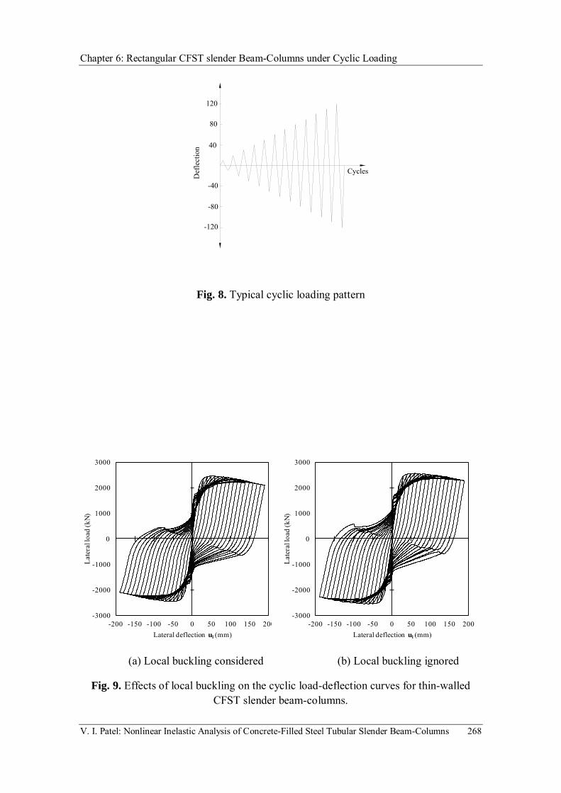
Chapter 6: Rectangular CFST slender Beam-Columns under Cyclic Loading
V. I. Patel: Nonlinear Inelastic Analysis of Concrete-Filled Steel Tubular Slender Beam-Columns 268
Fig. 8. Typical cyclic loading pattern
(a) Local buckling considered (b) Local buckling ignored
Fig. 9. Effects of local buckling on the cyclic load-deflection curves for thin-walled CFST slender beam-columns.
40
80
120
-40
-80
-120
Cycles
Def
lect
ion
-3000
-2000
-1000
0
1000
2000
3000
-200 -150 -100 -50 0 50 100 150 200
Late
ral l
oad
(kN)
Lateral deflection ul (mm)
-3000
-2000
-1000
0
1000
2000
3000
-200 -150 -100 -50 0 50 100 150 200
Late
ral l
oad
(kN)
Lateral deflection ul (mm)

Chapter 6: Rectangular CFST slender Beam-Columns under Cyclic Loading
V. I. Patel: Nonlinear Inelastic Analysis of Concrete-Filled Steel Tubular Slender Beam-Columns 269
(a) 22rLe (b) 30rL Fig. 10. Effects of column slenderness ratio on the cyclic load-deflection curves for
thin-walled CFST slender beam-columns.
(a) 50tD (b) 80tD
Fig. 11. Effects of tD ratio on the cyclic load-deflection curves for thin-walled CFST slender beam-columns.
-3000
-2000
-1000
0
1000
2000
3000
-200 -150 -100 -50 0 50 100 150 200
Late
ral l
oad
(kN)
Lateral deflection ul (mm)
-3000
-2000
-1000
0
1000
2000
3000
-200 -150 -100 -50 0 50 100 150 200
Late
ral l
oad
(kN)
Lateral deflection ul (mm)
-2500
-2000
-1500
-1000
-500
0
500
1000
1500
2000
2500
-200 -150 -100 -50 0 50 100 150 200
Late
ral l
oad
(kN)
Lateral deflection ul (mm)
-2500
-2000
-1500
-1000
-500
0
500
1000
1500
2000
2500
-200 -150 -100 -50 0 50 100 150 200
Late
ral l
oad
(kN)
Lateral deflection ul (mm)

Chapter 6: Rectangular CFST slender Beam-Columns under Cyclic Loading
V. I. Patel: Nonlinear Inelastic Analysis of Concrete-Filled Steel Tubular Slender Beam-Columns 270
(a) MPa60'cf (b) MPa100'
cf
Fig. 12. Effects of concrete compressive strengths on the cyclic load-deflection curves for thin-walled CFST slender beam-columns.
(a) MPa300syf (b) MPa690syf
Fig. 13. Effects of steel yield strengths on the cyclic load-deflection curves for thin-walled CFST slender beam-columns.
-2500
-2000
-1500
-1000
-500
0
500
1000
1500
2000
2500
-200 -150 -100 -50 0 50 100 150 200
Late
ral l
oad
(kN)
Lateral deflection ul (mm)
-2500
-2000
-1500
-1000
-500
0
500
1000
1500
2000
2500
-200 -150 -100 -50 0 50 100 150 200
Late
ral l
oad
(kN)
Lateral deflection ul (mm)
-2000
-1500
-1000
-500
0
500
1000
1500
2000
-120 -80 -40 0 40 80 120
Late
ral l
oad
(kN)
Lateral deflection ul (mm)
-2000
-1500
-1000
-500
0
500
1000
1500
2000
-120 -80 -40 0 40 80 120
Late
ral l
oad
(kN)
Lateral deflection ul (mm)

Chapter 6: Rectangular CFST slender Beam-Columns under Cyclic Loading
V. I. Patel: Nonlinear Inelastic Analysis of Concrete-Filled Steel Tubular Slender Beam-Columns 271
6.4 CONCLUDING REMARKS
In this chapter, a numerical model has been extended to the nonlinear analysis of high
strength thin-walled rectangular CFST slender beam-columns under constant axial load
and cyclically varying lateral loading. The numerical model simulates the progressive
local and post-local buckling by gradually redistributing the normal stresses within the
steel tube walls. The ultimate lateral loads and cyclic load-deflection curves for thin-
walled CFST beam-columns predicted by the numerical model were compared with
experimental results reported in the literature. Good agreement between numerical and
experimental results was achieved. The numerical model developed has been employed
to investigate the effects of cyclic local buckling, column slenderness ratio, depth-to-
thickness ratio, concrete compressive strengths and steel yield strengths on the ultimate
lateral loads and cyclic load-deflection curves of thin-walled CFST beam-columns. The
results obtained have been discussed.

Chapter 7: Conclusions
V. I. Patel: Nonlinear Inelastic Analysis of Concrete-Filled Steel Tubular Slender Beam-Columns 272
Chapter 7
CONCLUSIONS
7.1 SUMMARY
New numerical models based on fiber element formulations for simulating the nonlinear
inelastic behavior of CFST slender beam-columns under uniaxial loads, biaxial loads,
preloads or cyclic loading have been presented. The effects of concrete confinement,
initial geometric imperfections, second order and high strength materials were taken
into account in the numerical models. Effective width formulas were incorporated into
the numerical models to account for local buckling effects of the tube walls under stress
gradients. The progressive local buckling of thin-walled steel tubes in CFST beam-
columns was simulated by gradually redistributing the normal stresses within steel tube
walls.

Chapter 7: Conclusions
V. I. Patel: Nonlinear Inelastic Analysis of Concrete-Filled Steel Tubular Slender Beam-Columns 273
Axial load-moment-curvature relationships were computed from the cross-section
analysis of CFST beam-columns. Müller’s method algorithms were developed and
implemented in the numerical models to obtain solutions. Deflections caused by
preloads on the steel tubes were considered in the analysis of CFST slender beam-
columns. Computational procedures for determining the axial load-deflection responses
and axial load-moment interaction diagrams of thin-walled CFST slender beam-
columns under various loading conditions have been presented.
The ultimate strengths, ultimate lateral loads, axial load-deflection curves and cyclic
load-deflection responses were compared with experimental results reported in the
literature. The numerical models can effectively generate complete axial load-deflection
curves, axial load-moment strength interaction diagrams and cyclic load-deflection
responses for thin-walled CFST slender beam-columns with local buckling effects. A
set of performance indices was proposed and implemented in the numerical models to
quantify the performance of CFST beam-columns. The verified numerical models were
utilized to undertake parametric studies on the behavior of CFST slender beam-columns
with a wide range of parameters.
7.2 ACHIEVEMENTS
This thesis has made significant contributions to the area of CFST slender beam-
columns. Research achievements are summarized as follows:

Chapter 7: Conclusions
V. I. Patel: Nonlinear Inelastic Analysis of Concrete-Filled Steel Tubular Slender Beam-Columns 274
(1) Developed a numerical model for high strength rectangular CFST slender beam-
columns under axial load and uniaxial bending with local buckling effects.
(2) Developed a numerical model for biaxially loaded high strength rectangular CFST
slender beam-columns with local buckling effects.
(3) Developed a numerical model for circular high strength CFST slender beam-
columns with preload and confinment effects.
(4) Developed a numerical model for high strength thin-walled rectangular CFST
slender beam-columns with preload and local buckling effects.
(5) Developed a numerical model for high strength thin-walled rectangular CFST
slender beam-columns under axial load and cyclic loading with local buckling
effects.
(6) The numerical models developed provide structural designers with advanced
analysis and design tools that can be used to design safe and economical
composite buildings.
(7) Performance indices proposed can be used to quantify the contribution of the
concrete core and steel tube to the ultimate strengths of CFST slender beam-
columns in order to achieve designs.
(8) The numerical models proposed overcome the limitations of traditional plastic
analysis methods which are applicable to compact steel sections only. The
proposed numerical models allow the designer to analyse and design CFST beam-
columns made of the compact, non-compact or slender steel sections with any
strength grades and high strength concrete.
7.3 FURTHER RESEARCH

Chapter 7: Conclusions
V. I. Patel: Nonlinear Inelastic Analysis of Concrete-Filled Steel Tubular Slender Beam-Columns 275
The numerical models developed have been shown to be accurate computer simulation
tools which can be used to investigate the fundamental behavior of CFST slender beam-
columns. Further research is still needed to extend the numerical models developed to
composite columns under other loading conditions. The recommendations for further
research are summarized as follows:
(1) The numerical models developed can be directly used in the design of high
strength CFST beam-columns at room temperature. The effects of temperature
dependent material properties on the behavior of CFST beam-columns have not
been incorporated in the numerical models. Therefore, research on the
development of efficient and accurate numerical techniques for simulating the
nonlinear inelastic behavior of CFST slender beam–columns at elevated
temperature is needed.
(2) The numerical model presented in the thesis have been developed for high
strength CFST slender beam-columns and are not applicable to concrete encased
composite columns. Further research is needed to extend the numerical models to
concrete encased composite columns at ambient and elevated temperatures.
(3) The numerical models developed can be implemented in the advanced analysis
programs for the nonlinear analysis of composite frames with short-term loading.
The behavior of CFST beam-columns may change with time. The limitation of the
proposed model is that it did not account for the effects of long-term loading on
the behavior of CFST beam-columns. Therefore, the numerical models need to be
extended for the nonlinear time-dependent analysis of slender steel-concrete
composite beam-columns.

Chapter 7: Conclusions
V. I. Patel: Nonlinear Inelastic Analysis of Concrete-Filled Steel Tubular Slender Beam-Columns 276
(4) The proposed numerical models allow for the analysis and design of rectangular
thin-walled CFST beam-columns with a depth-to-thickness ratio up to 100.
Further research is needed to extend the numerical models developed to the
nonlinear inelastic analysis of thin-walled CFST beam-columns with depth-to-
thickness ratios greater than 100.

References
V. I. Patel: Nonlinear Inelastic Analysis of Concrete-Filled Steel Tubular Slender Beam-Columns 277
REFERENCES
Abed, F. Alhamaydeh, M. and Abdalla, S. (2013). “Experimental and numerical
investigations of the compressive behavior of concrete filled steel tubes (CFSTs).”
Journal of Constructional Steel Research, 80, 429-439.
ACI Committee 209 (1992). Prediction of creep, shrinkage and temperature effects in
concrete structures. Designing for effects of creep, shrinkage and temperature in
concrete structures, ACI SP27-3, Detroit, MI, 51-93.
\
ACI-318. (2002). Building code requirements for reinforced concrete. Detroit (MI):
ACI.
ACI (2011). Building code requirements for structural concrete and commentary. USA,
American Concrete Institute (ACI).
AIJ (1997). Recommendations for design and construction of concrete filled steel
tubular structures. Architectural Institutive of Japan, Tokyo, Japan.
AISC 360-05. (2005). Specification for structural steel buildings. Chicago (IL, USA),
American Institute of Steel Construction.
AISC 360-10. (2010). Specification for structural steel buildings. Chicago. Chicago,
Illinois: American Institute of Steel Construction.

References
V. I. Patel: Nonlinear Inelastic Analysis of Concrete-Filled Steel Tubular Slender Beam-Columns 278
AISC-LRFD (1993). Load and resistance factor specification for structural steel
buildings. AISC, Chicago, IL.
AISC-LRFD (1999). Load and resistance factor specification for structural steel
buildings. AISC, Chicago, IL.
AISC-LRFD (2005). Load and resistance factor specification for structural steel
buildings. AISC, Chicago, IL.
AS 4100 (1998). Australian Standard, Steel Structures, Sydney, Australia.
AS 5100 (2004). Bridge design, part 6: steel and composite construction. Sydney,
Australia.
AS 3600 (2009). Australian Standard, Cconcrete structures, Sydney, Australia.
Bridge, R. Q. (1976). “Concrete filled steel tubular columns.” School of Civil
Engineering, The University of Sydney, Sydney, Australia, Research Report No. R283.
Bridge, R. Q. and O'Shea, M. D. (1998). “Behaviour of thin-walled steel box sections
with or without internal restraint.” Journal of Constructional Steel Research, 47(1-2),
73-91.

References
V. I. Patel: Nonlinear Inelastic Analysis of Concrete-Filled Steel Tubular Slender Beam-Columns 279
BS 5400 (1979). Steel, concrete and composite bridges: Part: 5 Code of practice for
design of composite bridges, London, British Standards Institution.
CECS159 (2004). Technical specification for structures with concrete-filled rectnagular
steel tube members. Beijing, China (in Chinese).
Chen, S. F., Teng, J. G. and Chan, S. L. (2001). “Design of biaxially loaded short
composite columns of arbitrary section.” Journal of Structural Engineering, ASCE,
127(6), 678-685.
Choi, K. K. and Xiao, Y. (2010). “Analytical studies of concrete-filled circular steel
tubes under axial compression.” Journal of Structural Engineering, ASCE, 136(5), 565-
573.
Chung, J., Tsuda, K. and Matsui, C. (1999). “High-strength concrete filled square tube
columns subjected to axial loading.” The Seventh East Asia-Pacific Conference on
Structural Engineering & Construction, Kochi, Japan, 2, 955-960.
Chung, K. (2010). “Prediction of pre- and post-peak behavior of concrete-filled circular
steel tube columns under cyclic loads using fiber element method.” Thin-Walled
Structures, 48(2), 169-178.
References
V. I. Patel: Nonlinear Inelastic Analysis of Concrete-Filled Steel Tubular Slender Beam-Columns 280
Chung, K., Chung, J. and Choi, S. (2007). “Prediction of pre- and post-peak behavior of
concrete-filled square tube columns under cyclic loads using fiber element method.”
Thin-Walled Structures, 45(9), 747-758.
Chung, K. S., Kim, J. H. and Yoo, J. H. (2012). “Prediction of hysteretic behavior of
high-strength square concrete-filled steel tubular columns subjected to eccentric
loading.” International Journal of Steel Structures, 12(2), 243-252.
DBJ (2003). Technical specification for concrete-filled steel tubular structures. Fuzhou
China, The Department of Housing and Urban–Rural Development of Fujian Province
(in Chinese).
DBJ/T 13-51. (2010). Technical specification for concrete-filled steel tubular
structures. Fuzhou, China, The Department of Housing and Urban–Rural Development
of Fujian Province (in Chinese).
Ellobody, E., Young, B. and Lam, D. (2006). “Behaviour of normal and high strength
concrete-filled compact steel tube circular stub columns.” Journal of Constructional
Steel Research, 62(7), 706-715.
Ellobody, E. and Ghazy, M. F. (2012a). “Tests and design of stainless steel tubular
columns filled with polypropylene fibre reinforced concrete.” Proceedings of the 10th
international conference on advances in steel concrete composite and hybrid structures,
Singapore, 281-289.

References
V. I. Patel: Nonlinear Inelastic Analysis of Concrete-Filled Steel Tubular Slender Beam-Columns 281
Ellobody, E. and Ghazy, M. F. (2012b). “Experimental investigation of eccentrically
loaded fibre reinforced concrete-filled stainless steel tubular columns.” Journal of
Constructional Steel Research, 76, 167-176.
Ellobody, E. (2013). “Numerical modelling of fibre reinforced concrete-filled stainless
steel tubular columns.” Thin-Walled Structures, 63, 1-12.
El-Heweity, M. M. (2012). “On the performance of circular concrete-filled high
strength steel columns under axial loading.” Alexandria Engineering Journal, 51(2),
109-119.
EI-Tawil, S., Sanz-Picón, C. F. and Deierlein, G. G. (1995). “Evaluation of ACI 318
and AISC (LRFD) strength provisions for composite beam-columns.” Journal of
Constructional Steel Research, 34(1), 103-123.
Eurocode 3 (1992). Design of steel structuresm Part 1.1 General rules and rules for
buildings. London.
Eurocode 4 (1992). Design of composite steel and concrete structures, Part 1.1 general
rules and rules for buildings. Commision of European Communities, Brussels,
Belgium.
Eurocode 4 (1994). Design of composite steel and concrete structures, Part 1.1 General
rules and rules for buildings. London.

References
V. I. Patel: Nonlinear Inelastic Analysis of Concrete-Filled Steel Tubular Slender Beam-Columns 282
Eurocode 4 (2004). Design of composite steel and concrete structures. Part 1-1,
General rules and rules for buildings. CEN 2004.
Eurocode 4 (2005). Design of composite steel and concrete structures, Part 1-1,
General rules and rules for buildings, CEN, 2005.
Fam, A., Qie, F. S. and Rizkalla, S. (2004). “Concrete-filled steel tubes subjected to
axial compression and lateral cyclic loads.” Journal of Structural Engineering, ASCE,
130(4), 631-640.
Fujimoto, T., Mukai, A., Nishiyama, I. and Sakino, K. (2004). “Behavior of
eccentrically loaded concrete-filled steel tubular columns.” Journal of Structural
Engineering, ASCE, 130(2), 203-212.
Furlong, R. W. (1967). “Strength of steel-encased concrete beam columns.” Journal of
the Structural Division, ASCE, 93(5), 113-124.
Gajalakshmi, P. and Helena, H. J. (2012). “Behaviour of concrete-filled steel columns
subjected to lateral cyclic loading.” Journal of Constructional Steel Research, 75, 55-
63.
Ge, H. and Usami, T. (1992). “Strength of concrete-filled thin-walled steel box
columns: experiment.” Journal of Structural Engineering, ASCE, 118(11), 3036-3054.

References
V. I. Patel: Nonlinear Inelastic Analysis of Concrete-Filled Steel Tubular Slender Beam-Columns 283
Giakoumelis, G. and Lam, D. (2004). “Axial capacity of circular concrete-filled tube
columns.” Journal of Constructional Steel Research, 60(7), 1049-1068.
Guo, L., Zhang, S. and Xu, Z. (2011). “Behaviour of filled rectangular steel HSS
composite columns under bi-axial bending.” Advances in Structural Engineering, 14(2),
295-306.
Hajjar, J. F. and Gourley, B. C. (1996). “Representation of concrete-filled steel tube
cross-section strength.” Journal of Structural Engineering, 122(11), 1327-1335.
Han, L. H. (2002). “Tests on stub columns of concrete-filled RHS sections.” Journal of
Constructional Steel Research, 58(3), 353-372.
Han, L. H. (2007). Theory and practice of concrete-filled steel tubular structure.
Beijing, China (in Chinese).
Han, L. H., Tao, Z. and Yao, G. H. (2008). “Behaviour of concrete-filled steel tubular
members subjected to shear and constant axial compression.” Thin-Walled Structures,
46(7-9), 765-780.
Han, L. H. and Yang, Y. F. (2003). “Analysis of thin-walled steel RHS columns filled
with concrete under long-term sustained loads.” Thin-Walled Structures, 41(9), 849-
870.

References
V. I. Patel: Nonlinear Inelastic Analysis of Concrete-Filled Steel Tubular Slender Beam-Columns 284
Han, L. H., Yang, Y. F. and Tao, Z. (2003). “Concrete-filled thin-walled steel SHS and
RHS beam-columns subjected to cyclic loading.” Thin-Walled Structures, 41(9), 801-
833.
Han, L. H. and Yao, G. H. (2003). “Behaviour of concrete-filled hollow structural steel
(HSS) columns with pre-load on the steel tubes.” Journal of Constructional Steel
Research, 59(12), 1455-1475.
Hu, H. T., Huang, C. S., Wu, M. H. and Wu, Y. M. (2003). “Nonlinear analysis of
axially loaded concrete-filled tube columns with confinement effect.” Journal of
Structural Engineering, ASCE, 129(10), 1322-1329.
Klöppel, V. K., Goder, W. (1957). “An investigation of the load carrying capacity of
concrete filled steel tubes and development of design formula.” Der Stahlbau, 26(2),
44-50.
Knowles, R. B. and Park, R. (1969). “Strength of concrete-filled steel tubular columns.”
Journal of Structural Division, ASCE, 95(12), 2565-2587.
Lakshmi, B. and Shanmugam, N. E. (2002). “Nonlinear analysis of in-filled steel-
concrete composite columns.” Journal of Structural Engineering, ASCE, 128(7), 922-
933.

References
V. I. Patel: Nonlinear Inelastic Analysis of Concrete-Filled Steel Tubular Slender Beam-Columns 285
Lee, T. K. and Pan, A. D. E. (2001). “Analysis of composite beam-columns under
lateral cyclic loading.” Journal of Structural Engineering, ASCE, 127(2), 186-193.
Lee, S. H., Uy, B., Kim, S. H., Choi, Y. H. and Choi, S. M. (2011). “Behavior of high-
strength circular concrete-filled steel tubular (CFST) column under eccentric loading.”
Journal of Constructional Steel Research, 67(1), 1-13.
Liang, Q. Q. (2009a). “Performance-based analysis of concrete-filled steel tubular
beam–columns, Part II: verification and applications.” Journal of Constructional Steel
Research, 65(2), 351-362.
Liang, Q. Q. (2009b). “Performance-based analysis of concrete-filled steel tubular
beam–columns, part I: theory and algorithms.” Journal of Constructional Steel
Research, 65(2), 363-372.
Liang, Q. Q. (2009c). “Strength and ductility of high strength concrete-filled steel
tubular beam-columns.” Journal of Constructional Steel Research, 65(3), 687-698.
Liang, Q. Q. (2011a). “High strength circular concrete-filled steel tubular slender beam-
columns, Part I: Numerical analysis.” Journal of Constructional Steel Research, 67(2),
164-171.

References
V. I. Patel: Nonlinear Inelastic Analysis of Concrete-Filled Steel Tubular Slender Beam-Columns 286
Liang, Q. Q. (2011b). “High strength circular concrete-filled steel tubular slender
beamcolumns, Part II: Fundamental behavior.” Journal of Constructional Steel
Research, 67(2), 172-180.
Liang, Q. Q. and Fragomeni, S. (2009). “Nonlinear analysis of circular concrete-filled
steel tubular short columns under axial loading.” Journal of Constructional Steel
Research, 65(12), 2186-2196.
Liang, Q. Q. and Fragomeni, S. (2010). “Nonlinear analysis of circular concrete-filled
steel tubular short columns under eccentric loading.” Journal of Constructional Steel
Research, 66(2), 159-169.
Liang, Q. Q. and Uy, B. (2000). “Theoretical study on the post-local buckling of steel
plates in concrete-filled box columns.” Computers and Structures, 75(5), 479-490.
Liang, Q. Q., Uy, B., and Liew, J. Y. R. (2006). “Nonlinear analysis of concrete-filled
thin-walled steel box columns with local buckling effects.” Journal of Constructional
Steel Research, 62(6), 581-591.
Liang, Q. Q., Uy, B. and Liew, J. Y .R. (2007). “Local buckling of steel plates in
concrete-filled thin-walled steel tubular beam-columns.” Journal of Constructional
Steel Research, 63(3), 396-405.

References
V. I. Patel: Nonlinear Inelastic Analysis of Concrete-Filled Steel Tubular Slender Beam-Columns 287
Liew, J. Y. R. and Xiong, D. X. (2009). “Effect of preload on the axial capacity of
concrete-filled composite columns.” Journal of Constructional Steel Research, 65(3),
709-722.
Liew, J. Y. R. and Xiong, D. X. (2012). “Ultra-high strength concrete filled composite
columns for multi-storey building construction.” Advances in Structural Engineering,
15(9), 1487-1504.
LRFD. (1999). Load and resistance factor design specification for steel buildings.
American Institution of Steel Construction.
Liu, D. (2006). “Behaviour of eccentrically loaded high-strength rectangular concrete-
filled steel tubular columns.” Journal of Constructional Steel Research, 62(8), 839-846.
Lue, D. M., Liu, J. L. and Yen, T. (2007). “Experimental study on rectangular CFT
columns with high-strength concrete.” Journal of Constructional Steel Research, 63(1),
37-44.
Matsui, C., Tsuda, K. and Ishibashi, Y. (1995). “Slender concrete filled steel tubular
columns under combined compression and bending.” Proceedings of the 4th Pacific
Structural Steel Conference, Singapore, Pergamon, 3(10), 29-36.

References
V. I. Patel: Nonlinear Inelastic Analysis of Concrete-Filled Steel Tubular Slender Beam-Columns 288
Mander, J. B. and Priestley, M. J. N. and Park, R. (1988). “Theoretical stress–strain
model for confined concrete.” Journal of Structural Engineering, ASCE, 114(8), 1804-
1826.
Mursi, M. and Uy, B. (2006a). “Behaviour and design of fabricated high strength steel
columns subjected to biaxial bending part I: Experiments.” Advanced Steel
Construction, 2(4), 286-313.
Mursi, M. and Uy, B. (2006b). “Behaviour and design of fabricated high strength steel
columns subjected to biaxial bending part II: Analysis and design codes.” Advanced
Steel Construction, 2(4), 314-354.
Nakahara, H., Sakino, K., and Inai, E. (1998). “Analytical model for axial compressive
behavior of concrete filled square steel tubular columns.” Transaction of the Japan
Concrete Institute, 20, 171-178 (in Japanese).
Neogi, P. K., Sen, H. K. and Chapman, J. C. (1969). “Concrete-filled tubular steel
columns under eccentric loading.” The Structural Engineer, 47(5), 187-195.
O'Brien, A. D. and Rangan, B. V. (1993). “Tests on slender tubular steel columns filled
with high strength concrete.” Australian Civil Engineering Transactions, 35(4), 287-
292.

References
V. I. Patel: Nonlinear Inelastic Analysis of Concrete-Filled Steel Tubular Slender Beam-Columns 289
O'Shea, M. D. and Bridge, R. Q. (2000). “Design of circular thin-walled concrete filled
steel tubes.” Journal of structural engineering, ASCE, 126(11), 1295-1303.
Portolés, J. M., Romero, M. L., Bonet, J. L. and Filippou, F. C. (2011). “Experimental
study of high strength concrete-filled circular tubular columns under eccentric loading.”
Journal of Constructional Steel Research, 67(4), 623-633.
Portolés, J. M., Romero, M. L., Filippou, F. C. and Bonet, J. L. (2011). “Simulation and
design recommendations of eccentrically loaded slender concrete-filled tubular
columns.” Engineering Structures, 33(5), 1576-1593.
Rangan, B. V. and Joyce, M. (1992). “Strength of eccentrically loaded slender steel
tubular columns filled with high-strength concrete.” ACI Structural Journal, 89(6), 676-
681.
Roderick, J. W. and Rogers, D. F. (1969). “Load carrying capacity of simple composite
columns.” Proc. Am. Soc. Civ. Engrs., Journal of Structural Division, XCV(ST2), 209-
228.
Sakino, K., Nakahara, H., Morino, S. and Nishiyama, I. (2004). “Behavior of centrally
loaded concrete-filled steel-tube short columns.” Journal of Structural Engineering,
ASCE, 130(2), 180-188.

References
V. I. Patel: Nonlinear Inelastic Analysis of Concrete-Filled Steel Tubular Slender Beam-Columns 290
Sanz-Pic6n, C. F. (1992). Behavior of composite column cross sections under biaxial
bending, MS thesis, School of Civil and Envionmental Engineering, Cornell University,
Ithaca, N.Y.
Schneider, S. P. (1998). “Axially loaded concrete-filled steel tubes.” Journal of
Structural Engineering, ASCE, 124(10), 1125-1138.
Shakir-Khalil, H. and Zeghiche, J. (1989). “Experimental Behaviour of concrete-filled
rolled rectangular hollow-section columns.” The Structural Engineer, 67(19), 346-353.
Shakir-Khalil, H. and Mouli, M. (1990). “Further tests on concrete-filled rectangular
hollow-section columns.” The structural Engineer, 68(20), 405-413.
Shams, M. and Saadeghvaziri, M. A. (1997). “State of the art of concrete-filled steel
tubular columns.” ACI Structural Journal, 94(5), 558-571.
Shanmugam, N. E. and Lakshmi, B. (2001). “State of the art report on steel-concrete
composite columns.” Journal of Constructional Steel Research, 57(10), 1041-1080.
Shanmugam, N. E., Lakshmi, B. and Uy, B. (2002). “An analytical model for thin-
walled steel box columns with concrete in-fill.” Engineering Structures, 24(6), 825-838.
References
V. I. Patel: Nonlinear Inelastic Analysis of Concrete-Filled Steel Tubular Slender Beam-Columns 291
Gayathri, V., Shanmugam, N.E. and Choo, Y. S. (2004a). “Concrete-filled tubular
columns part 1- cross-section analysis.” International Journal of Structural Stability
and Dynamics, 4(4), 459-478.
Gayathri, V., Shanmugam, N.E. and Choo, Y. S. (2004b). “Concrete-filled tubular
columns part 2- column analysis.” International Journal of Structural Stability and
Dynamics, 4(4), 479-495.
Spacone, E. and El-Tawil, S. (2004). “Nonlinear analysis of steel-concrete composite
structures: state of the art.” Journal of Structural Engineering, ASCE, 130(2), 159-168.
Susantha, K. A. S., Ge, H. and Usami, T. (2001). “Uniaxial stress-strain relationship of
concrete confined by various shaped steel tubes.” Engineering Structures, 23(10), 1331-
1347.
Tang, J., Hino, S., Kuroda, I. and Ohta, T. (1996). “Modeling of stressstrain
relationships for steel and concrete in concrete filled circular steel tubular columns.”
Steel Construction Engineering, JSSC, 3(11), 35-46.
Thai, H. T. and Kim, S. E. (2011). “Nonlinear inelast ic analysis of concrete-filled
steel tubular frames.” Journal of Constructional steel Research , 67(12),
1797-1805.

References
V. I. Patel: Nonlinear Inelastic Analysis of Concrete-Filled Steel Tubular Slender Beam-Columns 292
Tomii, M., Sakino, K. (1979). “Elastic–plastic behavior of concrete filled square steel
tubular beam-columns.” Transactions of the Architectural Institute of Japan, 280, 111-
120.
Uy, B., Tao, Z. and Han, L. H. (2011). “Behaviour of short and slender concrete-filled
stainless steel tubular columns.” Journal of Constructional Steel Research, 67(3), 360-
378.
Varma, A. H., Ricles, J. M., Sause, R. and Lu, L. W. (2002), “Seismic behavior and
modeling of high strength composite concrete-filled steel tube (CFT) beam–columns.”
Journal of Constructional Steel Research, 58(5-8), 725-758.
Varma, A. H., Ricles, J. M., Sause, R. and Lu, L. W. (2004). “Seismic behavior and
design of high-strength square concrete-filled steel tube beam columns.” Journal of
Structural Engineering ASCE, 130(2), 169-179.
Vrcelj, Z. and Uy, B. (2002). “Strength of slender concrete-filled steel box columns
incorporating local buckling.” Journal of Constructional Steel Research, 58(2), 275-
300.
Wei, L., Han, L. H. and Zhao, X. L. (2012). “Axial strength of concrete-filled double
skin steel tubular (CFDST) columns with preload on steel tubes.” Thin-Walled
Structures, 56, 9-20.

References
V. I. Patel: Nonlinear Inelastic Analysis of Concrete-Filled Steel Tubular Slender Beam-Columns 293
Wu, B., Zhao, X. Y. and Zhang, J. S. (2012). “Cyclic behavior of thin-walled square
steel tubular columns filled with demolished concrete lumps and fresh concrete.”
Journal of Constructional Steel Research, 77, 69-81.
Xiong, D. X. and Zha, X. X. (2007). “A numerical investigation on the behaviour of
concrete-filled steel tubular columns under initial stresses.” Journal of Constructional
Steel Research, 63(5), 599-611.
Zhang, X. Q., Zhong, S. T., Yan, S. Z., Lin, W. and Cao, H. L. (1997). “Experimental
study about the effect of initial stress on bearing capacity of concrete-filled steel tubular
members under eccentric compression.” Journal of Harbin University of Civil
Engineering and Architecture, 30(1), 50-56 (in Chinese).
Zha, X. X. (1996). “The theoretical and experimental study on the behaviour of
concrete-filled steel tubular members subjected to compression-bending-torsion and
initial stresses on the steel tubes.” Ph.D. Dissertation, Harbin University of Civil
Engineering and Architecture, Harbin, China (in Chinese).
Zhang, S., Guo, L. and Tian, H.(2003). “Eccentrically loaded high strength concrete-
filled square steel tubes.” Proceedings of the International Conference on Advances in
Structures, Sydney, Australia, 2, 987-93.

References
V. I. Patel: Nonlinear Inelastic Analysis of Concrete-Filled Steel Tubular Slender Beam-Columns 294
Zhang, S. M., Guo, L. H., Ye, Z. L. and Wang, Y. Y. (2005). “Behavior of steel tube
and confined high strength concrete for concrete-filled RHS tubes.” Advances in
Strucutral Engineering, 8(2), 101-116.
Zubydan, A. H. and ElSabbagh, A. I. (2011). “Monotonic and cyclic behavior of
concrete-filled steel-tube beam-columns considering local buckling effect.” Thin-Walled
Structure, 49(4), 465-481.