Analysis of Optimal Stator Concentric Winding Patterns Design
Upload
sherman-johnstonCategory
view
260download
1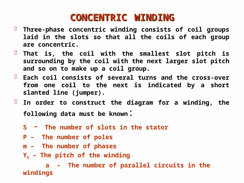
CONCENTRICCONCENTRIC WINDINGWINDING Three-phase concentric winding consists of coil groups laid in
the slots so that all the coils of each group are concentric. That is, the coil with the smallest slot pitch is surrounding by
the coil with the next larger slot pitch and so on to make up a coil group.
Each coil consists of several turns and the cross-over from one coil to the next is indicated by a short slanted line (jumper).
In order to construct the diagram for a winding, the following
data must be known:S - The number of slots in the stator
P – The number of poles
m – The number of phases
YS – The pitch of the winding
a – The number of parallel circuits in the windings

The pitch of the winding is determined by the formula
The pitch is the distance between two sides of a coil expressed as the difference between the numbers of the slots in which the sides lie.
Another important value of the winding of ac machines is the number of slot per phase per pole denoted by the letter q. It can be determined by the formula
Sometimes q is called a pole-phase group is defined as a group of coils of a phase under one pole.
The number of slots per pole per phase in concentric winding can be seen directly from the diagram. It is equal to the number of coils in a coil group.
P
SYS
Pole-pitch
Coil-sides
mP
Sq
q
Start (S)
Finish(F)
Jumper
A coil-group with 3-coils
Y3
Y1
Y2
1
2
310
12
11

CONNECTTNG COIL GROUPS INTO PHASES
As soon as all the coils have been laid in the slots, the coil groups are connected in to phases.
Each group is provided with two leads for the start and finish of the group.
The total number of leads is therefore twice the number of coil groups.
A stator winding must have six leads brought out to the terminal panel these leads being the beginnings and ends of the three phases.
All the reaming leads must be interconnected in the respective phases with in the winding.
It is now necessary to decide in order to determine the beginnings and ends of each phase.
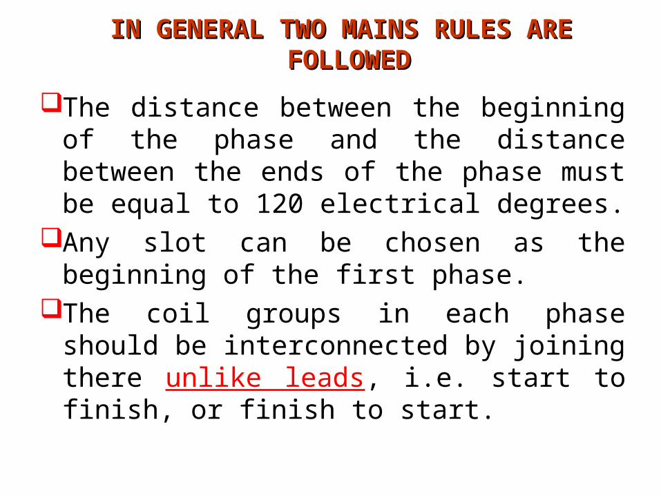
IN GENERAL TWO MAINS RULES ARE IN GENERAL TWO MAINS RULES ARE FOLLOWEDFOLLOWED
The distance between the beginning of the phase and the distance between the ends of the phase must be equal to 120 electrical degrees.
Any slot can be chosen as the beginning of the first phase.
The coil groups in each phase should be interconnected by joining there unlike leads, i.e. start to finish, or finish to start.

Example#1: on concentric winding Given data
S=24; p=4;m=3; a=1; type=Concentric• Solution
a) The number of coil groups, K
b) The number of slots per pole per phase, q
c) Coil pitch
The shorter coil pitch = YS-1=6-1=5 The larger coil pitch = YS+1=6+1=7
d) The electrical angle,
e) The angle between adjacent slots,
f) The distance between the beginning of each phase,
g) If the beginning of Phase A is slot 1, then the beginning of phase B is slot 1+=5 and the beginning of phase C is slot 1+2=1+8=9
64
24
p
SYS
243
24
pm
Sq
Full-Pitch ( average pitch)
i.e. there are two coils in a group
62
43
23K P
i.e. there is two coil groups per phase
7204180180 P
3024
720
S
slots430
120120

B
B’
A’
A
C
C’600
Phase sequence
A A C’ C’ B B A’ A’ C C B’ B’ A A C’ C’ B B A’ A’ C C B’ B’
1 2 3 4 5 6 7 8 9 10 11 12 13 14 15 16 17 18 19 20 21 22 23 24

connection Diagrams
A
A’
Phase A
1 8
2 7
13 20
14 19
I
IV
+7
+5
+7
+5
B
B’
Phase B
5 12
6 11
17 24
18 23
II
V
C’
C
Phase C
9 16
10 15
21 4
22 3VI
III
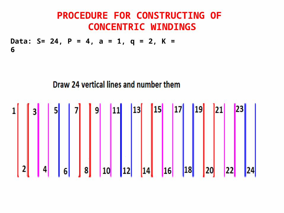
PROCEDURE FOR CONSTRUCTING OF CONCENTRIC WINDINGS
Data: S= 24, P = 4, a = 1, q = 2, K = 6
1
2 8
7
6
5
4
3 9
10
19
18
11 17
1614
1513
12
23
22
21
20 24
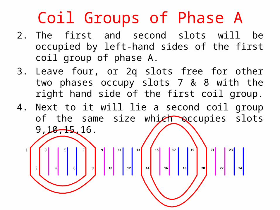
Coil Groups of Phase A2. The first and second slots will be occupied by left-hand
sides of the first coil group of phase A.
3. Leave four, or 2q slots free for other two phases occupy slots 7 & 8 with the right hand side of the first coil group.
4. Next to it will lie a second coil group of the same size which occupies slots 9,10,15,16.

Coil Groups of Phase B In order to find, where the second phase (B) should begin, it is
necessary to know the angle between slots in electrical degrees.
=180.P = 180.4 = 7200 – Electrical degree The angle between adjacent slots,
The distance between phase beginnings will have
1
2 8
7
6
5
4
3 9
10
19
18
11 17
1614
1513
12
23
22
21
20 24
slots430
120120
3024
720
S
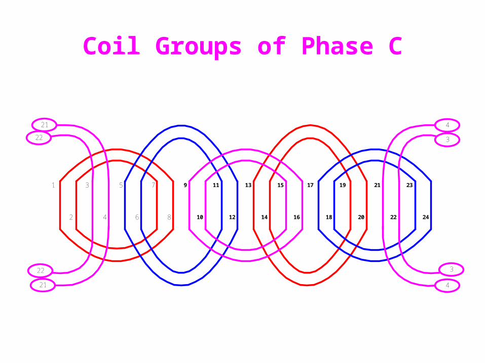
Coil Groups of Phase C
1
2 8
7
6
5
4
3 9
10
19
18
11 17
1614
1513
12
23
22
21
20 24
3
4
3
4
22
21
21
22

1
2 8
7
6
5
4
3 9
10
19
18
11 17
1614
1513
12
23
22
21
20 24
21
22 3
4
22
21
3
4
NSNS
Current direction
N
1-6
N
13-18
S
7-12
S
19-24

1
2 8
7
6
5
4
3 9
10
19
18
11 17
1614
1513
12
23
22
21
20 24
21
22 3
4
22
21
3
4
NSNS
Phase A – Coil groups interconnection

1
2 8
7
6
5
4
3 9
10
19
18
11 17
1614
1513
12
23
22
21
20 24
21
22 3
4
22
21
3
4
NSNS
Phase B – Coil groups interconnection

1
2 8
7
6
5
4
3 9
10
19
18
11 17
1614
1513
12
23
22
21
20 24
21
22 3
4
22
21
3
4
NSNS
Phase C – Coil groups interconnection
1
2 8
7
6
5
4
3 9
10
19
18
11 17
1614
1513
12
23
22
21
20 24
21
22 3
4
22
21
3
4
NSNS
A B’A’C’ CB
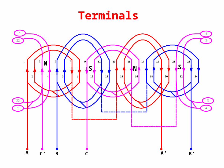
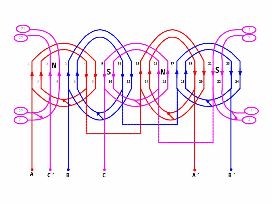
Terminals
1
2 8
7
6
5
4
3 9
10
19
18
11 17
1614
1513
12
23
22
21
20 24
21
22 3
4
22
21
3
4
NSNS
A B’A’C’ CB