COMSOL Multiphysics® Simulation of Flow in a Radial Flow ... · Introduction: In the design of...
4
COMSOL Multiphysics® Simulation of Flow in a Radial Flow Fixed Bed Reactor (RFBR) A. G. Dixon 1 , D. S. Polcari 1 , A. D. Stolo 1 , M. Tomida 1 1 Department of Chemical Engineering, Worcester Polytechnic Institute, Worcester, MA, USA Abstract Introduction: In the design of radial flow fixed bed reactors, it is important to ensure uniform flow distribution through the catalyst bed. A 2D axisymmetric model of a conceptual radial-flow reactor design was developed (Fig. 1) and was used to evaluate flow maldistribution through the catalyst bed and the pressure drop through the reactor for the specified flow rate. Effects of different catalyst pellet sizes, screen open area fractions and flow direction were simulated. Use of COMSOL MULTIPHYSICS®: The flow simulations used the CFD Module to implement incompressible turbulent flow (k-ε with wall functions). The equations for mass and momentum balances are: ρ(u·∇)u= ∇·[-ρl+(μ+ μ_T )(∇u+(∇u)^T )-2/3 ρkl]+F ρ∇·u=0 The term F represents forces acting on the fluid per unit volume. This term provides the resistance in the screens and in the bed (1,2). The equation for F in the catalyst bed was F=-µ/K*v-(C2B*ρ)/2*|v|*v ⃑ This is the Darcy-Forchheimer law which describes single-phase laminar flow through a porous medium, including a term for inertial resistance. The resistance in the screens was given by the porous jump model as F=-(C2S*ρ)/2*|v|*v ⃑ Different values for the inertial resistance C2S could be used for the inner and outer screens. Values for K and C2B were obtained from the Ergun equation for pressure drop in a packed bed, which depends on the particle size and bed void fraction. Values for C2S were determined from the equation of flow through square-edged holes on an equilateral triangular spacing (2). The flow resistance could be adjusted by changing the open area fraction of the screens and/or the catalyst particle diameter. Baseline conditions were for 10% open screens and ⅛ × 3⁄16 in. (D × L) pellets. Results: Flow and pressure contours are shown in Fig. 2 for specified inlet velocity and outlet pressure, under baseline conditions. Normal flow direction was downwards in Fig. 2(a) and 2(b). This case gave a quite large ΔP and reasonably uniform distribution of flow. A large contribution to the overall ΔP was caused by the flow constriction into the outer annulus and at the bed exit where the radial and axial flows merged. Flow in the reverse direction was investigated (Fig. 2c) and gave lower ΔP at the cost of much worse flow distribution. Fig. 3 shows the flow field and re-circulation regions for normal flow associated with higher
Transcript of COMSOL Multiphysics® Simulation of Flow in a Radial Flow ... · Introduction: In the design of...
COMSOL Multiphysics® Simulation of Flow in aRadial Flow Fixed Bed Reactor (RFBR)
A. G. Dixon1, D. S. Polcari1, A. D. Stolo1, M. Tomida1
1Department of Chemical Engineering, Worcester Polytechnic Institute, Worcester, MA, USA
Abstract
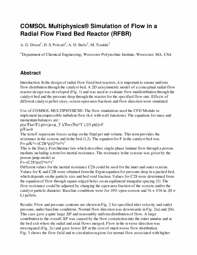
Introduction: In the design of radial flow fixed bed reactors, it is important to ensure uniformflow distribution through the catalyst bed. A 2D axisymmetric model of a conceptual radial-flowreactor design was developed (Fig. 1) and was used to evaluate flow maldistribution through thecatalyst bed and the pressure drop through the reactor for the specified flow rate. Effects ofdifferent catalyst pellet sizes, screen open area fractions and flow direction were simulated.
Use of COMSOL MULTIPHYSICS®: The flow simulations used the CFD Module toimplement incompressible turbulent flow (k-ε with wall functions). The equations for mass andmomentum balances are:ρ(u·∇)u=∇·[-ρl+(μ+μ_T )(∇u+(∇u)^T )-2/3 ρkl]+Fρ∇·u=0The term F represents forces acting on the fluid per unit volume. This term provides theresistance in the screens and in the bed (1,2). The equation for F in the catalyst bed wasF=-µ/K*v-(C2B*ρ)/2*|v|*v ⃑This is the Darcy-Forchheimer law which describes single-phase laminar flow through a porousmedium, including a term for inertial resistance. The resistance in the screens was given by theporous jump model as F=-(C2S*ρ)/2*|v|*v ⃑Different values for the inertial resistance C2S could be used for the inner and outer screens.Values for K and C2B were obtained from the Ergun equation for pressure drop in a packed bed,which depends on the particle size and bed void fraction. Values for C2S were determined fromthe equation of flow through square-edged holes on an equilateral triangular spacing (2). Theflow resistance could be adjusted by changing the open area fraction of the screens and/or thecatalyst particle diameter. Baseline conditions were for 10% open screens and ⅛ × 3⁄16 in. (D ×L) pellets.
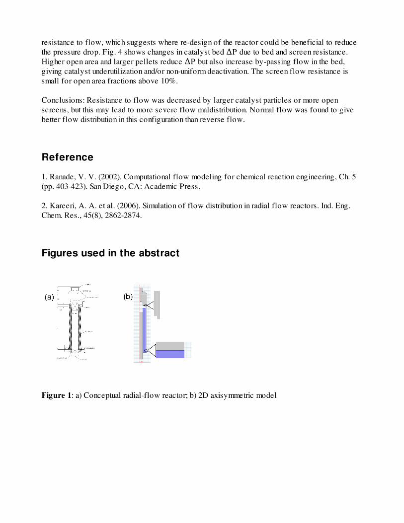
Results: Flow and pressure contours are shown in Fig. 2 for specified inlet velocity and outletpressure, under baseline conditions. Normal flow direction was downwards in Fig. 2(a) and 2(b).This case gave a quite large ΔP and reasonably uniform distribution of flow. A largecontribution to the overall ΔP was caused by the flow constriction into the outer annulus and atthe bed exit where the radial and axial flows merged. Flow in the reverse direction wasinvestigated (Fig. 2c) and gave lower ΔP at the cost of much worse flow distribution.Fig. 3 shows the flow field and re-circulation regions for normal flow associated with higher
resistance to flow, which suggests where re-design of the reactor could be beneficial to reducethe pressure drop. Fig. 4 shows changes in catalyst bed ΔP due to bed and screen resistance.Higher open area and larger pellets reduce ΔP but also increase by-passing flow in the bed,giving catalyst underutilization and/or non-uniform deactivation. The screen flow resistance issmall for open area fractions above 10%.
Conclusions: Resistance to flow was decreased by larger catalyst particles or more openscreens, but this may lead to more severe flow maldistribution. Normal flow was found to givebetter flow distribution in this configuration than reverse flow.
Reference
1. Ranade, V. V. (2002). Computational flow modeling for chemical reaction engineering, Ch. 5(pp. 403-423). San Diego, CA: Academic Press.
2. Kareeri, A. A. et al. (2006). Simulation of flow distribution in radial flow reactors. Ind. Eng.Chem. Res., 45(8), 2862-2874.
Figures used in the abstract
Figure 1: a) Conceptual radial-flow reactor; b) 2D axisymmetric model
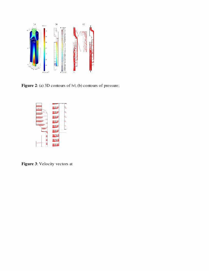
Figure 2: (a) 3D contours of |v|; (b) contours of pressure;
Figure 3: Velocity vectors at

Figure 4: Effect of pellet size & screen