Computer Simulation of Involute Tooth Generation -...
25
22 Computer Simulation of Involute Tooth Generation Cuneyt Fetvaci Istanbul University, Mechanical Engineering Department, Turkey 1. Introduction Gearing is an essential component of many machines. From aerospace to high-speed automation, from missiles to submarines, few machines can operate without gears. Involute gears are the most popular power transmission devices for parallel axes owing to their simple geometry, easy manufacturing, and constant gear ratio even when the centre distance has been changed. Spur gears are the most popular form and the most efficient type of gearing for the cost when transmitting power and uniform rotary motion from one parallel shaft to another. In mass production of gears, generating-type cutters are used. According to the type of relative motion between cutter and gear blank, generating cutters are classified as: rack cutters, hob cutters and gear shapers. Generation cutting is based on the fact that two involute gears of the same module and pitch mesh together - the gear blank and the cutter. This method makes to use one cutter for machining gears of the same module with a varying number of teeth. Rack-type cutters (rack or hob) can only generate external gears. Both external and internal gears can be generated by a pinion-type cutter. Figure 1 displays generating-type cutters. For cylindrical gears in applications with uniform load-rotation conditions, an optimized and separate design of traction and thrust flank is desirable. This can be achieved by using different pressure angles for traction and thrust flank, which results in asymmetric tooth geometries. The load-carrying capacity of the gear mechanism can be improved without disturbing the material quality by using asymmetric profiles (Muni et al., 2007). The computer simulation of gear cutting enables us to investigate the influence of design parameters on the generated profile before manufacturing. Undercutting and zero topland can be detected in design phase. Also the physical behaviour of the gear under operating conditions can be simulated and investigated. Therefore possible faults due to the inaccurate design can be detected for preventing time and material lost. An accurate geometrical representation of gear tooth surfaces is the fundamental starting point for developing a reliable computerized gear design which includes tooth contact analysis and stress analysis. Therefore, a good knowledge of the gear geometry is required. www.intechopen.com
-
Upload
trinhxuyen -
Category
Documents
-
view
245 -
download
3
Transcript of Computer Simulation of Involute Tooth Generation -...
22
Computer Simulation of Involute Tooth Generation
Cuneyt Fetvaci Istanbul University, Mechanical Engineering Department,
Turkey
1. Introduction
Gearing is an essential component of many machines. From aerospace to high-speed
automation, from missiles to submarines, few machines can operate without gears. Involute
gears are the most popular power transmission devices for parallel axes owing to their
simple geometry, easy manufacturing, and constant gear ratio even when the centre
distance has been changed. Spur gears are the most popular form and the most efficient type
of gearing for the cost when transmitting power and uniform rotary motion from one
parallel shaft to another.
In mass production of gears, generating-type cutters are used. According to the type of
relative motion between cutter and gear blank, generating cutters are classified as: rack
cutters, hob cutters and gear shapers. Generation cutting is based on the fact that two
involute gears of the same module and pitch mesh together - the gear blank and the cutter.
This method makes to use one cutter for machining gears of the same module with a
varying number of teeth. Rack-type cutters (rack or hob) can only generate external gears.
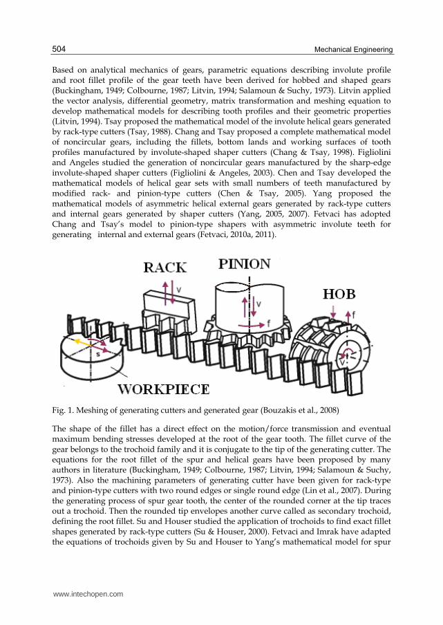
Both external and internal gears can be generated by a pinion-type cutter. Figure 1 displays
generating-type cutters.
For cylindrical gears in applications with uniform load-rotation conditions, an optimized
and separate design of traction and thrust flank is desirable. This can be achieved
by using different pressure angles for traction and thrust flank, which results in
asymmetric tooth geometries. The load-carrying capacity of the gear mechanism can be
improved without disturbing the material quality by using asymmetric profiles (Muni et
al., 2007).
The computer simulation of gear cutting enables us to investigate the influence of design
parameters on the generated profile before manufacturing. Undercutting and zero topland
can be detected in design phase. Also the physical behaviour of the gear under operating
conditions can be simulated and investigated. Therefore possible faults due to the inaccurate
design can be detected for preventing time and material lost. An accurate geometrical
representation of gear tooth surfaces is the fundamental starting point for developing a
reliable computerized gear design which includes tooth contact analysis and stress analysis.
Therefore, a good knowledge of the gear geometry is required.
www.intechopen.com
Mechanical Engineering
504
Based on analytical mechanics of gears, parametric equations describing involute profile and root fillet profile of the gear teeth have been derived for hobbed and shaped gears (Buckingham, 1949; Colbourne, 1987; Litvin, 1994; Salamoun & Suchy, 1973). Litvin applied the vector analysis, differential geometry, matrix transformation and meshing equation to develop mathematical models for describing tooth profiles and their geometric properties (Litvin, 1994). Tsay proposed the mathematical model of the involute helical gears generated by rack-type cutters (Tsay, 1988). Chang and Tsay proposed a complete mathematical model of noncircular gears, including the fillets, bottom lands and working surfaces of tooth profiles manufactured by involute-shaped shaper cutters (Chang & Tsay, 1998). Figliolini and Angeles studied the generation of noncircular gears manufactured by the sharp-edge involute-shaped shaper cutters (Figliolini & Angeles, 2003). Chen and Tsay developed the mathematical models of helical gear sets with small numbers of teeth manufactured by modified rack- and pinion-type cutters (Chen & Tsay, 2005). Yang proposed the mathematical models of asymmetric helical external gears generated by rack-type cutters and internal gears generated by shaper cutters (Yang, 2005, 2007). Fetvaci has adopted Chang and Tsay’s model to pinion-type shapers with asymmetric involute teeth for generating internal and external gears (Fetvaci, 2010a, 2011).
Fig. 1. Meshing of generating cutters and generated gear (Bouzakis et al., 2008)
The shape of the fillet has a direct effect on the motion/force transmission and eventual maximum bending stresses developed at the root of the gear tooth. The fillet curve of the gear belongs to the trochoid family and it is conjugate to the tip of the generating cutter. The equations for the root fillet of the spur and helical gears have been proposed by many authors in literature (Buckingham, 1949; Colbourne, 1987; Litvin, 1994; Salamoun & Suchy, 1973). Also the machining parameters of generating cutter have been given for rack-type and pinion-type cutters with two round edges or single round edge (Lin et al., 2007). During the generating process of spur gear tooth, the center of the rounded corner at the tip traces out a trochoid. Then the rounded tip envelopes another curve called as secondary trochoid, defining the root fillet. Su and Houser studied the application of trochoids to find exact fillet shapes generated by rack-type cutters (Su & Houser, 2000). Fetvaci and Imrak have adapted the equations of trochoids given by Su and Houser to Yang’s mathematical model for spur
www.intechopen.com
Computer Simulation of Involute Tooth Generation
505
gears with asymmetric involute teeth (Fetvaci & Imrak, 2008). Besides, simulated motion path of the rack cutter has been illustrated. Fetvaci has studied trochoidal paths of the pinion-type cutter during the generation of internal and external spur gears with asymmetric involute teeth (Fetvaci, 2010a, 2011).
The relative positions of the cutter during gear teeth generating process can be used for
determining chip geometry for further analysis on tool wear and tool life. Tang et al.
presented a computer simulation method of spur gear generating process with the sharp
edge rack- and pinion-type cutters using Visual Lisp as programming language and
AutoCAD as graphical display tools (Tang et al., 2008). Fetvaci presented computer
simulation methods for generating asymmetric involute spur gears with rounded edge
generating cutters (Fetvaci, 2010a, 2010b, 2011).
In this study, accurate mathematical models of the generating-type cutters for spur gear production are given, and trochoidal paths that determine the shape of generated tooth root fillet are investigated. Indirect gear design depending on the pre-selected set of cutting tool parameters is considered. Based on the mathematical models, computer codes have also been developed to compute the coordinates of the gear tooth profile generated by different types of cutters like cutter with sharp tip, partially round and full round tip for symmetric and asymmetric involute spur gears. Computer graphs are obtained to visualise the effect of tool parameters on generated gears before manufacturing.
The content of this chapter is organized as follows: In Section 2, the matematical models of generating cutter surfaces are studied according to Litvin’s vector approach. The mathematical models: the locus of the rack- and pinion-type cutter surfaces, the equation of meshing and the generated gear tooth surfaces are given in Section 3. Trochoidal paths of the cutter tips are investigated in Section 4. As a result, Section 5 deals with computer simulation of the generating process for the verification and the validation of the matematical models. Simulated motion path of the cutter during generation process is also illustrated. The varieties of the cutter tip geometry are investigated. Finally, a conclusive summary of this study is given in Section 6.
2. Generating tooth surfaces
2.1 Rack cutter surfaces
For simplicity, the generation of spur gears with shaper cutters can be simplified into a two-
dimensional problem. Due to the asymmetry of the rack cutter, left and right sides of the
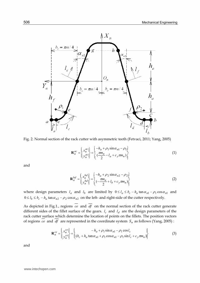
cutter are considered seperately. Figure 2. presents the design of the normal section of a rack
cutter n , where regions ac and bd are the left- and right-side top lands, regions ce and
df are the left- and right-side fillets and, regions eg and fh are the left- and right-side
working regions.
The regions ac and bd are used to generate the bottomland of asymmetric spur gear and al
and bl represent design parameters of normal section of the rack cutter. In order to generate
complete profile of the rack cutter surface a tooth of rack cutter will be repeated for
,.2,1,0yc . Equations of regions ac and bd of the rack cutter normal section can be
represented in the coordinate system ),,( nnnn ZYXS by the following equations (Yang, 2005).
www.intechopen.com
Mechanical Engineering
506
Fig. 2. Normal section of the rack cutter with asymmetric teeth (Fetvaci, 2011; Yang, 2005)
)2
(
sin 111
nyan
na
acn
acnac
n mclm
h
y
x R (1)
and
)2
(
sin 222
nybn
na
bdn
bdnbd
n mclm
h
y
x R (2)
where design parameters al and bl are limited by 111 costan0 nnaca hbl and
222 costan0 nnacb hbl on the left- and right-side of the cutter respectively.
As depicted in Fig.1., regions ce and df on the normal section of the rack cutter generate
different sides of the fillet surface of the gears. cl and dl are the design parameters of the
rack cutter surface which determine the location of points on the fillets. The position vectors
of regions ce and df are represented in the coordinate system nS as follows (Yang, 2005) :
)sincostan(
cossin
1111
111
nycnnac
cna
cen
cence
n mclhb
lh
y
x
R (3)
and
www.intechopen.com
Computer Simulation of Involute Tooth Generation
507
)sincostan(
cossin
2222
222
nydnnac
dna
dfn
dfndf
n mclhb
lh
y
x
R (4)
where design parameters cl and dl are limited by 1900 ncl and 2900 ndl
respectively.
As shown in Fig. 1., two straight edges eg and fh of the rack cutter are used to generate
the left- and right-side tooth surface of the asymmetric helical gear, respectively. The symbol
nm represents the normal module. The position vector of regions eg and fh are
represented in the coordinate system nS as follows (Yang, 2005):
)sin(
cos
1
1
nynec
ne
egn
egneg
n mclb
l
y
x
R (5)
and
)sin(
cos
2
2
nynfc
nf
fhn
fhnfh
n mclb
l
y
x
R (6)
where el and fl are the design parameters of the rack cutter surface which determine the
location of points on the working surface. el and fl are limited by
11 cos/cos/ naena hlh and 22 cos/cos/ nafna hlh for the left- and right-side of
the rack cutter respectively. The surface unit normals of the regions ac to fh of the rack
cutter surfaces are represented by (Litvin, 1994),
)~(
)~(
faj
fhaci
l
l
nj
in
nj
in
in
kR
kR
n (7)
where nk is the unit vector of the nZ -axis.
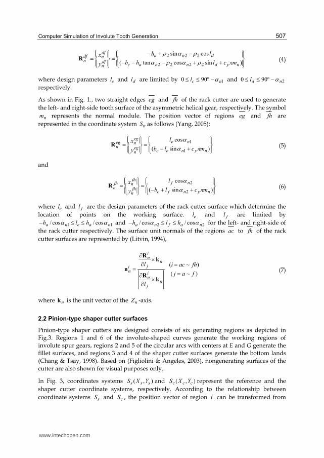
2.2 Pinion-type shaper cutter surfaces
Pinion-type shaper cutters are designed consists of six generating regions as depicted in
Fig.3. Regions 1 and 6 of the involute-shaped curves generate the working regions of
involute spur gears, regions 2 and 5 of the circular arcs with centers at E and G generate the
fillet surfaces, and regions 3 and 4 of the shaper cutter surfaces generate the bottom lands
(Chang & Tsay, 1998). Based on (Figliolini & Angeles, 2003), nongenerating surfaces of the
cutter are also shown for visual purposes only.
In Fig. 3, coordinates systems ),( sss YXS and ),( ccc YXS represent the reference and the
shaper cutter coordinate systems, respectively. According to the relationship between
coordinate systems sS and cS , the position vector of region i can be transformed from
www.intechopen.com
Mechanical Engineering
508
coordinate systems sS to cS by applying the following homogeneous coordinate
transformation (Litvin, 1994):
is
is
ic
ici
cy
x
y
xR
sincos
cossin (8)
Fig. 3. Geometry of the shaper cutter
where tan2/ sN , sN is the number of shaper cutter teeth and is the
pressure angle of the cutter at the pitch point, as depicted in Fig. 1. Supercript i represents
regions 1, 2, 3, 4, 5 and 6.
For simplicity the mathematical models of the left side generating surfaces of the cutter are
given. As shown in Fig. 3., the regions 1 and 6 of the shaper cutter are used are used to
generate the different sides of the working tooth surfaces of involute spur gears. is the
design parameter of the cutter surface which determines the location of points on the
involute region and its effective range is m 0 . The position vector of region 1 is
represented in the coordinate system sS as follows (Chang & Tsay, 1998):
sincos
cossin
1
11
bb
bb
s
ss
rr
rr
y
xR (9)
www.intechopen.com
Computer Simulation of Involute Tooth Generation
509
where br is the radius of base circle. Substituting Eq. (9) into Eq. (8) yields the position
vector of region 1 represented in coordinate system cS as follows (Chang & Tsay,
1998):
)cos()sin(
)sin()cos(1
bb
bbc
rr
rrR (10)
Regions 2 and 5 of the shaper cutter generate different sides of the fillet surfaces of spur
gears. As shown in Fig. 1, parameter of the cutter surface determines the location of
points on the fillet region and its effective range is ))/((tan2/0 11
bm r . The
tangents of the involute curve and circular arc at point A should be same and continuous.
Therefore, the center E of the circular arc is located on the line PA , as depicted in Fig. 3. The
position vector of region 2 is represented in the coordinate system sS as follows (Chang &
Tsay, 1998):
)sin(sinsincos
)cos(coscossin
11
112
mmmmbmb
mmmmbmbs
rr
rrR
(11)
where 1 is the radius tip fillet surface of the generating cutter, and m is the maximum
extension angle of the involute curve at point A. Similarly, the position vector of region 2
can be represented in coordinate system cS as follows:
)cos()cos()cos()sin(
)sin()sin()sin()cos(
11
112
mmmmbmb
mmmmbmbc
rr
rrR (12)
As depicted in Fig. 3, the regions 3 and 4 are used to generate the bottomland
of the machined gear. represents a design parameter of shaper cutter and its
effective range is sm N2/tan2/ . Based on the cutter geometry,
equation of region 3, represented in coordinate system sS , can be expressed as (Chang &
Tsay, 1998)
cos
sin
3
33
a
a
s
ss
r
r
y
xR (13)
where 12
12 )( mbba rrr is the radius of the tip circle of the cutter and
))/((tan2/ 11
bm r . Similarly, the position vector of region 3 can be represented
in coordinate system cS as follows (Chang & Tsay, 1998):
)cos(
)sin(3
a
a
c
cc
r
r
y
xR (14)
Based on the differential geometry, the unit normal vectors of the above mentioned shaper
cutter surface represented in coordinate system cS are (Litvin, 1994)
www.intechopen.com
Mechanical Engineering
510
cj
ic
cj
ic
c
kdl
dR
kdl
dR
n
(15)
where ck is the unit vector of the cZ -axis. Parameter jl represents , and ,
respectively.
By substituting Eq. (10) in Eq. (15), the unit normal vector of region 1 can be obtained as
follows (Chang & Tsay, 1998) :
)cos(
)sin(1
11
yc
xcc
n
nn (16)
By substituting Eq. (12) in Eq. (15), the unit normal vector of region 2 can be obtained as
follows (Chang & Tsay, 1998):
)cos(
)sin(2
22
m
m
yc
xcc
n
nn (17)
By substituting Eq. (14) in Eq. (15), the unit normal vector of region 3 can be obtained as
follows (Chang & Tsay, 1998):
)cos(
)sin(3
33
yc
xcc
n
nn (18)
The equations for the right side of the cutter are similar to those of left’s, provided that parameters are calculated according to corresponding pressure angle, and all equations corresponding to cX coordinate are assigned an appropriate sign.
3. Generated gear tooth surfaces
3.1 Generating with rack-cuttter
To derive the mathematical model for the complete tooth profile of involute spur gears with
asymmetric teeth, coordinate systems ),,( nnnn ZYXS , ),,( 1111 ZYXS and ),,( hhhh ZYXS
should be set up. The coordinate systems nS , 1S and hS are attached to the rack cutter,
involute gear, and gear housing, respectively as shown in Fig. 4. 1Z , nZ and hZ are
determined by the right-hand co-ordinate system. During the generation process, the rack
cutter translates a distance 11 prS while the gear blank rotates rotates by an angle 1 .
The mathematical model of the generated gear tooth surface is a combination of the meshing
equation and the locus of the rack cutter surfaces according to gearing theory (Litvin, 1994).
Applying the following homogeneous coordinate transformation matrix equation makes it
possible to obtain the locus of the cutter represented in coordinate system 1S as follows:
www.intechopen.com
Computer Simulation of Involute Tooth Generation
511
icn
i M RR 11 (19)
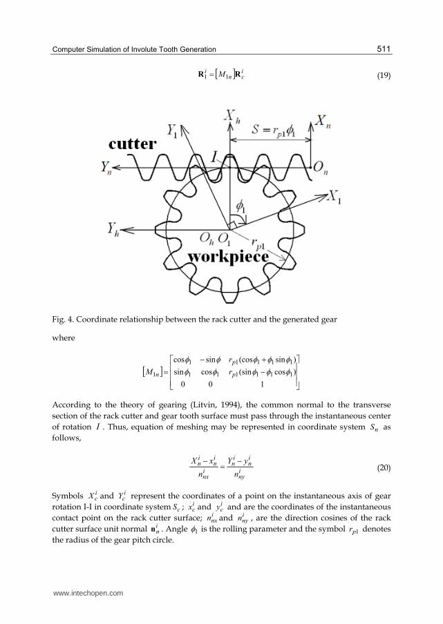
Fig. 4. Coordinate relationship between the rack cutter and the generated gear
where
100
)cos(sincossin
)sin(cossincos
111111
11111
1
p
p
n r
r
M
According to the theory of gearing (Litvin, 1994), the common normal to the transverse
section of the rack cutter and gear tooth surface must pass through the instantaneous center
of rotation I . Thus, equation of meshing may be represented in coordinate system nS as
follows,
iny
in
in
inx
in
in
n
yY
n
xX (20)
Symbols icX and i
cY represent the coordinates of a point on the instantaneous axis of gear
rotation I-I in coordinate system cS ; icx and i
cy and are the coordinates of the instantaneous
contact point on the rack cutter surface; inxn and i
nyn , are the direction cosines of the rack
cutter surface unit normal inn . Angle 1 is the rolling parameter and the symbol 1pr denotes
the radius of the gear pitch circle.
www.intechopen.com
Mechanical Engineering
512
Recalling that Eq. (20) represent the equation of meshing between the generated tooth surface and the rack cutter, it can be rewritten as follows:
)/()()( 11inxp
iny
in
inx
inj nrnxnyl (21)
By simultaneously considering Eqs. (19) and (21), the mathematical model of the generated gear can now be obtained. After substitutions, the computer graph of the pinion teeth can be plotted by using an appropriate software.
3.2 Generating with pinion cutter
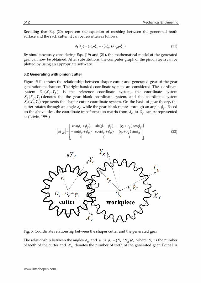
Figure 5 illustrates the relationship between shaper cutter and generated gear of the gear
generation mechanism. The right-handed coordinate systems are considered. The coordinate
system ),( fff YXS is the reference coordinate system, the coordinate system
),( ggg YXS denotes the the gear blank coordinate system, and the coordinate system
),( ccc YXS represents the shaper cutter coordinate system. On the basis of gear theory, the
cutter rotates through an angle c while the gear blank rotates through an angle g . Based
on the above idea, the coordinate transformation matrix from cS to gS can be represented
as (Litvin, 1994)
100
sin)()cos()sin(
cos)()sin()cos(
ggcgcgc
ggcgcgc
gc rr
rr
M
(22)
Fig. 5. Coordinate relationship between the shaper cutter and the generated gear
The relationship between the angles g and c is cgcg NN )/( where cN is the number
of teeth of the cutter and gN denotes the number of teeth of the generated gear. Point I is
www.intechopen.com
Computer Simulation of Involute Tooth Generation
513
the instantaneous center of rotation and cr and gr are the standard pitch radii of the shaper
cutter and the gear, respectively.
According to the theory of gearing (Litvin, 1994), the mathematical model of the generated
gear tooth surface is a combination of the meshing equation and the locus of the rack cutter
surfaces. The locus of the shaper cutter surface, expressed in coordinate system gS , can be
determined as follows (Litvin, 1994):
)6,...,1(, iM icgc
ig RR (23)
When two gear surfaces are meshing, both meshing surfaces should remain in
tangency throughout the contact under ideal contact conditions. Conjugate tooth profiles
have a common surface normal vector at the contact point which intersects the
instantaneous axis of rotation (pitch point I) for a parallel axis gear pair. Therefore, the
equation of meshing can be represented using coordinate system ),,( cccc ZYXS as follows
(Litvin, 1994):
icy
icc
icx
icc
n
yY
n
xX (24)
where ccc rX cos and ccc rY sin are coordinates of the pitch point I represented in
coordinate system cS ; icx and i
cy are the surface coordinates of the shaper cutter; symbols icxn
and icyn symbolize the components of the common unit normal represented in
coordinate system cS . In Eqs. (23) and (24), supercript i represents regions 1 through 6 of
the corresponding shaper cutter surfaces.
The mathematical model of the generated gear tooth surfaces is a combination of the
meshing equation and the locus of the rack cutter surfaces according to the gearing theory.
Hence, the mathematical model of the gear tooth surfaces can be obtained by
simultaneously considering Eqs. (23) and (24).
4. Trochoidal paths of generating cutter
4.1 Rack cutter
In gear practice, the gometry of the tooth root fillet is of primary importance regarding the
local stress concentration, which has a direct effect on the bending strength. The cutting
teeth of the hobs (or rack-cutter) have generally rounded corners. During the generating
process, the center of the rounding follows the trochoidal path called as primary trochoid
(Su& Houser, 2000).
A general point T on the primary trochoid is depicted in Fig.6. Adopting the approach
presented in (Su & Houser, 2000), following equations are derived according to the
given mathematical model in a previous study of the present author (Fetvaci & Imrak, 2008).
The equation of the primary trochoid which is the envelope of the center of round tip T0
is:
www.intechopen.com
Mechanical Engineering
514
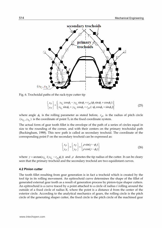
Fig. 6. Trochoidal paths of the rack-type cutter tip
)sincos(cossin
)cossin(sincos
111111
111111
00
00
pTT
pTT
T
T
ryx
ryx
y
x (25)
where angle 1 is the rolling parameter as stated before, 1pr is the radius of pitch circle
),(00 TT yx is the coordinate of point T0 in the fixed coordinate system.
The actual form of gear tooth fillet is the envelope of the path of a series of circles equal in
size to the rounding of the corner, and with their centers on the primary trochoidal path
(Buckingham, 1988). This new path is called as secondary trochoid. The coordinate of the
corresponding point F on the secondary trochoid can be expressed as:
)cos(
)sin(
1
1
T
T
F
F
y
x
y
x (26)
where ))/(arctan( 1100 pTT ryx and denotes the tip radius of the cutter. It can be cleary
seen that the primary trochoid and the secondary trochoid are two equidistant curves.
4.2 Pinion cutter
The tooth fillet resulting from gear generation is in fact a trochoid which is created by the tool tip in its rolling movement. An epitrochoid curve determines the shape of the fillet of generated external gear tooth as a result of generation process by pinion-type shaper cutters. An epitrochoid is a curve traced by a point attached to a circle of radius r rolling around the outside of a fixed circle of radius R, where the point is a distance d from the center of the exterior circle. According to the analytical mechanics of gears, the rolling circle is the pitch circle of the generating shaper cutter, the fixed circle is the pitch circle of the machined gear
www.intechopen.com
Computer Simulation of Involute Tooth Generation
515
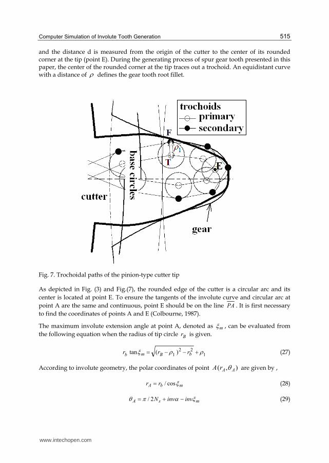
and the distance d is measured from the origin of the cutter to the center of its rounded corner at the tip (point E). During the generating process of spur gear tooth presented in this paper, the center of the rounded corner at the tip traces out a trochoid. An equidistant curve with a distance of defines the gear tooth root fillet.
Fig. 7. Trochoidal paths of the pinion-type cutter tip
As depicted in Fig. (3) and Fig.(7), the rounded edge of the cutter is a circular arc and its
center is located at point E. To ensure the tangents of the involute curve and circular arc at
point A are the same and continuous, point E should be on the line PA . It is first necessary
to find the coordinates of points A and E (Colbourne, 1987).
The maximum involute extension angle at point A, denoted as m , can be evaluated from
the following equation when the radius of tip circle Br is given.
122
1 )(tan bBmb rrr (27)
According to involute geometry, the polar coordinates of point ),( AArA are given by ,
mbA rr cos/ (28)
msA invinvN 2/ (29)
www.intechopen.com
Mechanical Engineering
516
The rectangular coordinates of point E can then be expressed in terms of Ex and Ey ,
)sin(cos 1 AmAAE rx (30)
)cos(sin 1 AmAAE ry (31)
)/(tan 1EEE xy (32)
A general point on the primary trochoid which is the envelope of the center of round tip is
depicted in Fig. 7. Applying the homogeneous coordinate transformation matrix given in
Eq. (22), the equation of the primary trochoid (epitrochoid curve) can be written as follows:
ggcgcEgcE
ggcgcEgcE
T
T
rryx
rryx
y
x
sin)()cos()sin(
cos)()sin()cos( (33)
where ),( EE yx is the coordinate of point E , c and g are the rolling parameters, cr and
gr are the pitch circle radius of the shaper and the machined gear, respectively.
The actual form of spur gear tooth fillet is the envelope of the path of a series of circles with
their geometric centers on the primary trochoidal path. This new path is called as secondary
trochoid which is the paralel curve of the primary trochoid. As a result, the coordinate of the
corresponding point F on the secondary trochoid can be expressed as
22
1
TT
TTF
yx
yxx
(34)
22
1
TT
TTF
yx
xyy
(35)
where 1 denotes the tip rounding radius of the shaper cutter, cTT ddxx / and
cTT ddyy / .
5. Computer graphs of tooth surfaces
Computer graphs of generating and generated surfaces can be obtained by using a
programming language and graphic processor. In this study codes are developed by using
GW-BASIC language to obtain the coordinates of the surfaces. GRAPHER 2-D Graphing
System is used for displaying computer graphs of the cutters and gears. Also the ANSYS
Preprocessor module is used for displaying gear generating process. Illustrative examples
are given for both rack- and pinion-type cutters for different types of tool tip geometries.
For rack-type generation, types of tip fillet geometry are selected from the study proposed
by Alipiev (Alipiev, 2009, 2011) and the related geometries displayed in the table are
adopted to the present mathematical model. Table 1 displays the variation of tip geometry
of the rack cutters.
www.intechopen.com
Computer Simulation of Involute Tooth Generation
517
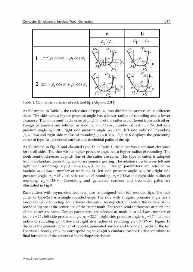
Table 1. Geometric varieties of rack tool tip (Alipiev, 2011)
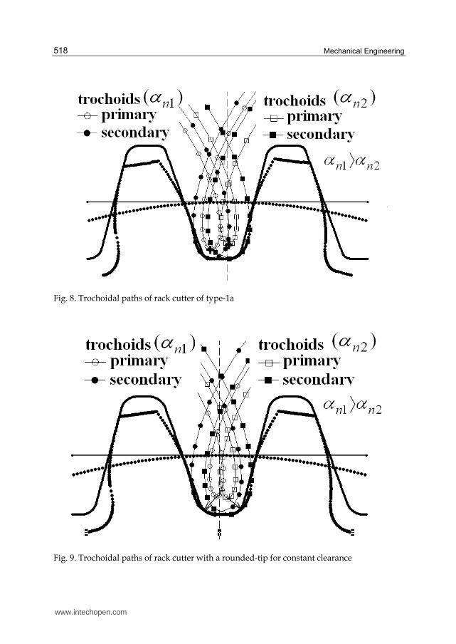
As illustrated in Table 1, the rack cutter of type-1a has different clearances at its different
sides. The side with a higher pressure angle has a lower radius of rounding and a lower
clearance. The tooth semi-thicknesses at pitch line of the cutter are different from each other.
Design parameters are selected as module mmm 5.2 , number of teeth 24z , left side
pressure angle 201 , right side pressure angle 152 , left side radius of rounding
m 2.01 and right side radius of rounding m 3.02 . Figure 8 displays the generating
cutter of type-1a , generated surface and trochoidal paths of the tip.
As illustrated in Fig. 2. and classifed type-1b in Table 1, the cutter has a constant clearance
for its all sides. The side with a higher pressure angle has a higher radius of rounding. The
tooth semi-thicknesses at pitch line of the cutter are same. This type of cutter is adopted
from the standard generating rack to asymmetric gearing. The relation ship between left and
right side roundings is )sin1()sin1( 2211 . Design parameters are selected as
module mmm 5.2 , number of teeth 24z , left side pressure angle 201 , right side
pressure angle 152 , left side radius of rounding m 38.01 and right side radius of
rounding m 33.02 . Generating and generated surfaces and trochoidal paths are
illustrated in Fig 9.
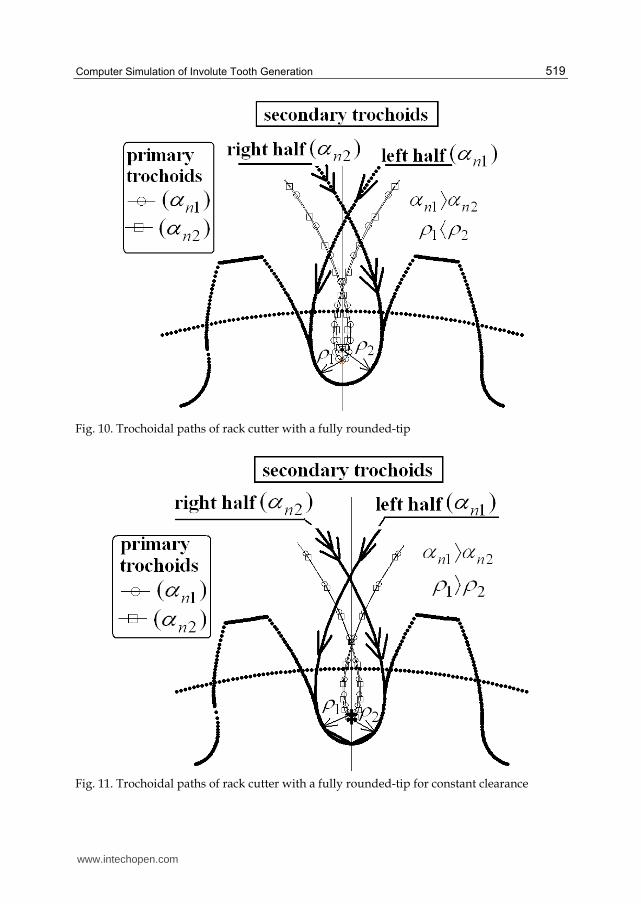
Rack cutters with asymmetric teeth can also be designed with full rounded tips. The rack
cutter of type-2a has a single rounded edge. The side with a higher pressure angle has a
lower radius of rounding and a lower clearance. As depicted in Table 1 the centers of the
rounded tip are at the center line of the cutter tooth. The tooth semi-thicknesses at pitch line
of the cutter are same. Design parameters are selected as module mmm 5.2 , number of
teeth 24z , left side pressure angle 5.221 , right side pressure angle 152 , left side
radius of rounding m 4.01 and right side radius of rounding m 587.02 . Figure 10
displays the generating cutter of type-1a, generated surface and trochoidal paths of the tip.
For visual clearity, only the corresponding halves (of secondary trochoids) that contribute to
final formation of the generated tooth shape are shown.
www.intechopen.com
Mechanical Engineering
518
Fig. 8. Trochoidal paths of rack cutter of type-1a
Fig. 9. Trochoidal paths of rack cutter with a rounded-tip for constant clearance
www.intechopen.com
Computer Simulation of Involute Tooth Generation
519
Fig. 10. Trochoidal paths of rack cutter with a fully rounded-tip
Fig. 11. Trochoidal paths of rack cutter with a fully rounded-tip for constant clearance
www.intechopen.com
Mechanical Engineering
520
As classifed type-2b in Table 1, the cutter has a constant clearance for its all sides. The side
with a higher pressure angle has a higher radius of rounding. The tooth semi-thicknesses at
pitch line of the cutter are different. The relation ship between left and right side roundings
is )sin1()sin1( 2211 . Design parameters are selected as module mmm 5.2 ,
number of teeth 24z , left side pressure angle 5.221 , right side pressure angle
152 , left side radius of rounding m 514.01 and right side radius of rounding
m 428.02 . Generating and generated surfaces and trochoidal paths are illustrated in Fig.
11. For visual clearity, only the corresponding halves (of secondary trochoids) that
contribute to final formation of the generated tooth shape are shown.
The geometric varieties of the rounded corner of pinion-type cutter tooth for generating
symmetric and asymmetric involute gear teeth profiles can also be investigated. Illustrated
examples for pinion-type generation were given by the present author (Fetvaci, 2011).
Table 2 displays possible tip geometries of pinion-type shaper cutters for standard tooth
height.
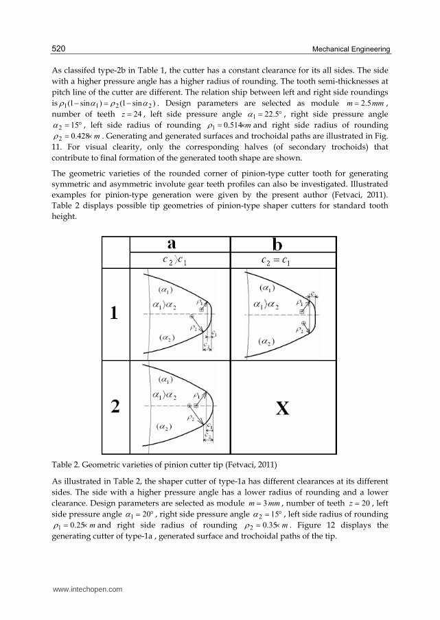
Table 2. Geometric varieties of pinion cutter tip (Fetvaci, 2011)
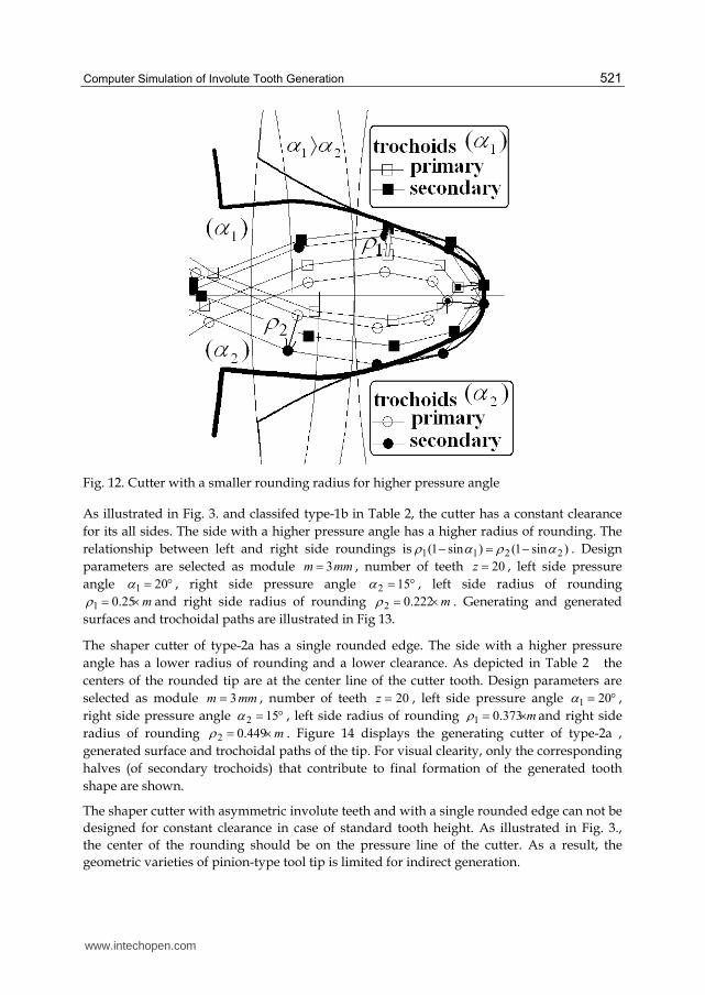
As illustrated in Table 2, the shaper cutter of type-1a has different clearances at its different
sides. The side with a higher pressure angle has a lower radius of rounding and a lower
clearance. Design parameters are selected as module mmm 3 , number of teeth 20z , left
side pressure angle 201 , right side pressure angle 152 , left side radius of rounding
m 25.01 and right side radius of rounding m 35.02 . Figure 12 displays the
generating cutter of type-1a , generated surface and trochoidal paths of the tip.
www.intechopen.com
Computer Simulation of Involute Tooth Generation
521
Fig. 12. Cutter with a smaller rounding radius for higher pressure angle
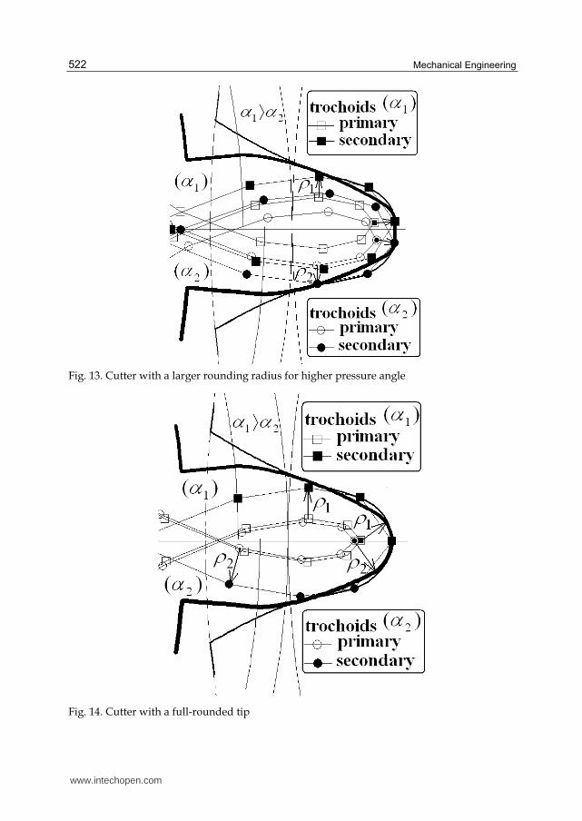
As illustrated in Fig. 3. and classifed type-1b in Table 2, the cutter has a constant clearance
for its all sides. The side with a higher pressure angle has a higher radius of rounding. The
relationship between left and right side roundings is )sin1()sin1( 2211 . Design
parameters are selected as module mmm 3 , number of teeth 20z , left side pressure
angle 201 , right side pressure angle 152 , left side radius of rounding
m 25.01 and right side radius of rounding m 222.02 . Generating and generated
surfaces and trochoidal paths are illustrated in Fig 13.
The shaper cutter of type-2a has a single rounded edge. The side with a higher pressure
angle has a lower radius of rounding and a lower clearance. As depicted in Table 2 the
centers of the rounded tip are at the center line of the cutter tooth. Design parameters are
selected as module mmm 3 , number of teeth 20z , left side pressure angle 201 ,
right side pressure angle 152 , left side radius of rounding m 373.01 and right side
radius of rounding m 449.02 . Figure 14 displays the generating cutter of type-2a ,
generated surface and trochoidal paths of the tip. For visual clearity, only the corresponding
halves (of secondary trochoids) that contribute to final formation of the generated tooth
shape are shown.
The shaper cutter with asymmetric involute teeth and with a single rounded edge can not be
designed for constant clearance in case of standard tooth height. As illustrated in Fig. 3.,
the center of the rounding should be on the pressure line of the cutter. As a result, the
geometric varieties of pinion-type tool tip is limited for indirect generation.
www.intechopen.com
Mechanical Engineering
522
Fig. 13. Cutter with a larger rounding radius for higher pressure angle
Fig. 14. Cutter with a full-rounded tip
www.intechopen.com
Computer Simulation of Involute Tooth Generation
523
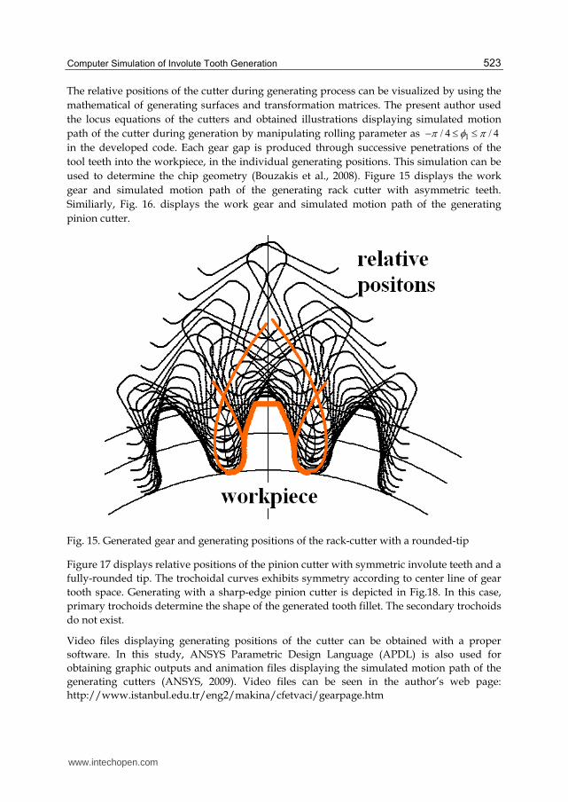
The relative positions of the cutter during generating process can be visualized by using the
mathematical of generating surfaces and transformation matrices. The present author used
the locus equations of the cutters and obtained illustrations displaying simulated motion
path of the cutter during generation by manipulating rolling parameter as 4/4/ 1
in the developed code. Each gear gap is produced through successive penetrations of the
tool teeth into the workpiece, in the individual generating positions. This simulation can be
used to determine the chip geometry (Bouzakis et al., 2008). Figure 15 displays the work
gear and simulated motion path of the generating rack cutter with asymmetric teeth.
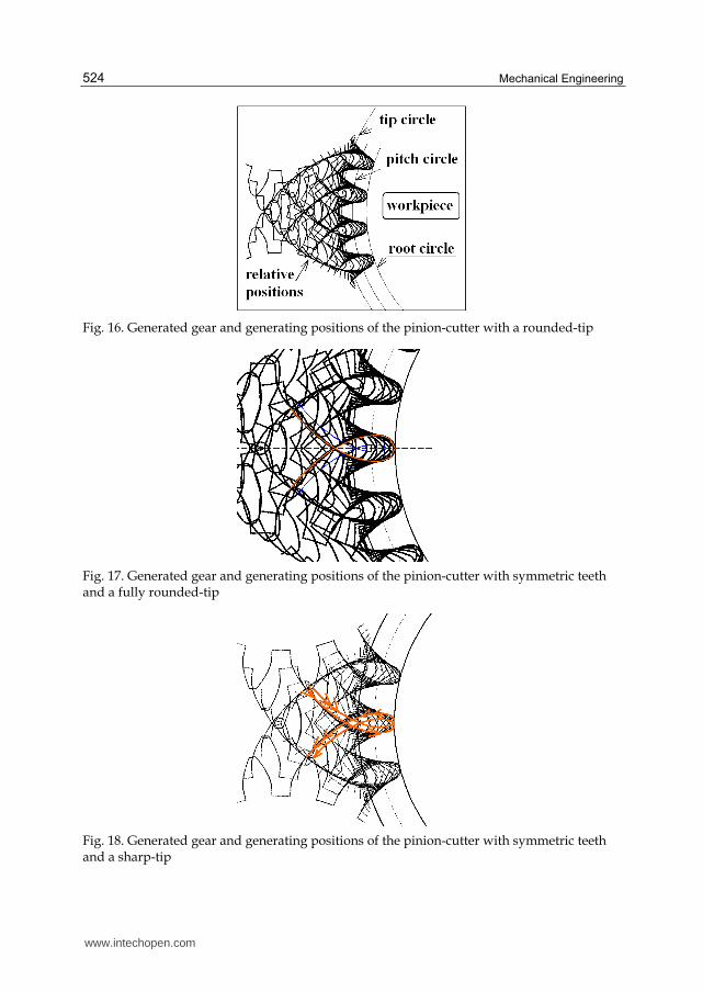
Similiarly, Fig. 16. displays the work gear and simulated motion path of the generating
pinion cutter.
Fig. 15. Generated gear and generating positions of the rack-cutter with a rounded-tip
Figure 17 displays relative positions of the pinion cutter with symmetric involute teeth and a
fully-rounded tip. The trochoidal curves exhibits symmetry according to center line of gear
tooth space. Generating with a sharp-edge pinion cutter is depicted in Fig.18. In this case,
primary trochoids determine the shape of the generated tooth fillet. The secondary trochoids
do not exist.
Video files displaying generating positions of the cutter can be obtained with a proper
software. In this study, ANSYS Parametric Design Language (APDL) is also used for
obtaining graphic outputs and animation files displaying the simulated motion path of the
generating cutters (ANSYS, 2009). Video files can be seen in the author’s web page:
http://www.istanbul.edu.tr/eng2/makina/cfetvaci/gearpage.htm
www.intechopen.com
Mechanical Engineering
524
Fig. 16. Generated gear and generating positions of the pinion-cutter with a rounded-tip
Fig. 17. Generated gear and generating positions of the pinion-cutter with symmetric teeth and a fully rounded-tip
Fig. 18. Generated gear and generating positions of the pinion-cutter with symmetric teeth and a sharp-tip
www.intechopen.com
Computer Simulation of Involute Tooth Generation
525
6. Conclusion
In this study, computerized tooth profile generation of involute gears manufactured by rack- and pinion-type cutters are studied based on Litvin’s vector method. Based on Yang’s application mathematical model of rack cutter with asymmetric involute teeth is given. Trochoidal paths of the rack tool tip are investigated. For pinion-type generation Asymmetric involute teeth is adopted to Chang and Tsay’s application. The developed computer program provides the investigation of the effect of tool parameters on the generated tool profile before manufactured. Trochoidal paths traced by the generating tool tip are investigated. It has been seen that geometric varieties of the rounded corner of pinion-type cutter determines the position of trochoidal paths relative to the center line of tooth space of the generated gear. Because of the position of the center of the tip rounding, there is a limitation on the geometric varieties of pinion-type cutter tip. Based on the given mathematical models, the simulated motion path of the generating cutters are also investigated. The relative position of the cutter to the workpiece has been illustrated. The simulation of shaper cutting action can be used to determine the chip geometry for further analysis about tool wear and tool life. The mathematical models can be extended to generalized mathematical model of the involute gears including spur and helical beveloid (involute conical) gears.
7. References
Alipiev, O. (2009). Geometric Synthesis of Symmetric and Asymmetric Involute Meshing using the Method of Realized Potential. General Machine Design Conference, p. 43-50, Ruse – Bulgaria, October 15-16, 2009
Alipiev, O. (2011). Geometric Design of Involute Spur Gear Drives with Symmetric and Asymmetric Teeth using the Realized Potential Method. Mechanism and Machine Theory, Vol. 46, No. 1, (January 2011), pp. 10-32, ISSN 0094-114X
ANSYS. (2009). ANSYS Parametric Design Language Guide. Available from, http://www1.ansys.com/customer/content/documentation/120/ans_apdl.pdf Bouzakis, K.-D., Lili, E., Michailidis, N. & Friderik, O. 2008. Manufacturing of Cylindrical
Gears by Generating Cutting Processes: A Critical Synthesis of Analysis Methods. CIRP Annals - Manufacturing Technology, Vol. 57, No.2, 2008, pp. 676-696.
Buckingham, E. (1949). Analytical Mechanics of Gears, McGraw-Hill, New York, USA Chang, S.-L. & Tsay, C.-B. (1998). Computerized Tooth Profile Generation and Undercut
Analysis of Noncircular Gears Manufactured with Shaper Cutters. Journal of Mechanical Design, Vol. 120, No. 1, (March 1998), pp. 92-99.
Chen, C.-F & Tsay, C.-B. (2005). Tooth Profile Design for the Manufacture of Helical Gear Sets with Small Numbers of Teeth, International Journal of Machine Tools and Manufacture, Vol. 45, No. 12-13, (October 2005), pp. 1531-1541
Colbourne, J.R. (1987). The Geometry of Involute Gears, Springer-Verlag, New Jersey, USA Fetvaci, C. & İmrak, E. (2008). Mathematical Model of a Spur Gear with Asymmetric
Involute Teeth and its Cutting Simulation. Mechanics Based Design of Structures and Machines , Vol. 36, No. 1, pp. 34- 46, ISSN 1539-7734
Fetvacı, C. (2010a). Definition of Involute Spur Gear Profiles Generated By Gear-Type Shaper Cutters. Mechanics Based Design of Structures and Machines. Vol.38, No. 4, pp. 481-492
www.intechopen.com
Mechanical Engineering
526
Fetvaci, C. (2010b). Computer Simulation of Helical Gears with Asymmetric Involute Teeth. Journal of The Faculty of Engineering and Architecture of Gazi University, Vol. 25, No. 3, (September 2010), pp. 441-447, ISSN 1300-1884
Fetvaci, C. (2011). Computer Simulation of Asymmetric Involute Spur Gears Manufactured by Generating-Type Cutters . Engineers and Machinery, Vol. 52, No. 616, (May 2011), pp. 60-69
Figliolini, G. & Angeles, J. (2003). The Synthesis of Elliptical Gears Generated by Shaper-Cutters. Journal of Mechanical Design, Vol.125, No. 4, (December 2003), pp. 793-801, 2003.
Lin, T., Ou, H. & Li, R. (2007). A Finite Element Method for 3-D Static and Dynamic Contact/Impact Analysis of Gear Drives. Computer Methods in Applied Mechanics and Engineering. Vol. 196, No. 9-12, (February 2007), pp. 1716-1728.
Litvin, F.L. (1994). Gear Geometry and Applied Theory, Prentice Hall, New Jersey, USA Muni, D.V., Kumar, S. & Muthuveerappan, G. (2007). Optimization of Asymmetric Spur
Gear Drives for Maximum Bending Strength Using Direct Gear Design Method. Mechanics Based Design of Structures and Machines, Vol.35, No.2, pp. 127-145
Salamoun, C. & Suchy, M. (1973). Computation of Helical or Spur Gear Fillets. Mechanism and Machine Theory, Vol. 8, No. 3, (Autumn 1973), pp. 305-322, ISSN 0094-114X
Su, X. & Houser, D.R. (2000). Characteristics of Trochoids and their Application to Determining Gear Teeth Fillet Shapes. Mechanism and Machine Theory, Vol. 35, No. 2, (February 2000), pp. 291–304, ISSN 0094-114X
Tang, X., Ren, F., Jiang, Y. & Gao, S. (2008). Geometric Modeling and Dynamic Simulation of Involute Gear by Generating Method, Proceedings 13th International Conference on Geometry and Graphics, pp. 233-234, Dresden, Germany, August 4-8, 2008
Tsay, C.-B. (1988). Helical Gears with Involute Shaped Teeth: Geometry, Computer Simulation, Tooth Contact Analysis and Stress Analysis. Journal of Mechanical Design, Vol. 110, No. 4 , pp. 482-491
Yang, S.-C. (2005). Yang, Mathematical Model of a Helical Gear with Asymmetric Involute Teeth and its Analysis. International Journal of Advanced Manufacturing Technology, Vol. 26, No. 5-6, (September 2005), pp. 448-456, ISSN 0268-3768
Yang, S.-C. (2007). Study on an Internal Gear with Asymmetric Involute Teeth. Mechanism and Machine Theory, Vol. 42, No. 8, (August 2007), pp. 977-994
www.intechopen.com
Mechanical EngineeringEdited by Dr. Murat Gokcek
ISBN 978-953-51-0505-3Hard cover, 670 pagesPublisher InTechPublished online 11, April, 2012Published in print edition April, 2012
InTech EuropeUniversity Campus STeP Ri Slavka Krautzeka 83/A 51000 Rijeka, Croatia Phone: +385 (51) 770 447 Fax: +385 (51) 686 166www.intechopen.com
InTech ChinaUnit 405, Office Block, Hotel Equatorial Shanghai No.65, Yan An Road (West), Shanghai, 200040, China
Phone: +86-21-62489820 Fax: +86-21-62489821
The book substantially offers the latest progresses about the important topics of the "Mechanical Engineering"to readers. It includes twenty-eight excellent studies prepared using state-of-art methodologies by professionalresearchers from different countries. The sections in the book comprise of the following titles: powertransmission system, manufacturing processes and system analysis, thermo-fluid systems, simulations andcomputer applications, and new approaches in mechanical engineering education and organization systems.
How to referenceIn order to correctly reference this scholarly work, feel free to copy and paste the following:
Cuneyt Fetvaci (2012). Computer Simulation of Involute Tooth Generation, Mechanical Engineering, Dr. MuratGokcek (Ed.), ISBN: 978-953-51-0505-3, InTech, Available from:http://www.intechopen.com/books/mechanical-engineering/computer-simulation-of-involute-tooth-generation


![Untitled Document [mech.utah.edu]mech.utah.edu/~me3200/hws/F02HWS/F02_HW7.pdf · A 40-tooth gear has AGMA standard full-depth involute teeth with diametral pitch of 10. Calculate](https://static.fdocuments.in/doc/165x107/5a9ea5907f8b9a8e178ba615/untitled-document-mechutahedumechutahedume3200hwsf02hwsf02hw7pdfa-40-tooth.jpg)