Compressive Strength Characteristics of Concrete-Filled Plastic Tubes Short Columns
7
International Journal of Science and Research (IJSR) ISSN (Online): 2319-7064 Impact Factor (2012): 3.358 Volume 3 Issue 9, September 2014 www.ijsr.net Licensed Under Creative Commons Attribution CC BY Compressive Strength Characteristics of Concrete- Filled Plastic Tubes Short Columns Gathimba Naftary K. 1* , Oyawa Walter O. 2 , Mang'uriu Geoffrey N. 3 1 Department of Civil Engineering, Jomo Kenyatta University of Agriculture and Technology, P.O. box 62000-00200 Nairobi, Kenya 2 Department of Civil Engineering, Jomo Kenyatta University of Agriculture and Technology P.O. box 62000-00200 Nairobi, Kenya 3 School of Civil Engineering and Geospatial Engineering, Jomo Kenyatta University of Agriculture and Technology, P.O. box 62000-00200 Nairobi, Kenya Abstract: This paper presents the results of an experimental programme which investigated the effect, on compressive strength, of using unplasticized polyvinyl (UPVC) tubes in confining short concrete columns. Plastic tubes having varying diameters and heights were used to confine concrete of different strengths. The resulting composite columns were subjected to concentric axial compressive loads until failure. The principal failure mode was a typical shear failure. The results indicated that compressive strength of the column specimens increase with increased concrete strength while the same decreased with increased column height, albeit by a small margin since all the columns considered were short columns. A comparison of the ultimate load carrying capacity and column compressive strength was then made between unconfined and the resulting composite column. Strength increased between 1.18 to 3.65 times the unconfined strength. The study shows greater potentiality of plastics as concrete confinement construction materials of the near future. Keywords: Short columns, confine, UPVC, Composite, compressive strength 1. Introduction In many countries, including here in Kenya, there have been various cases of collapse of buildings either under construction or when in use. Also, the rapid deterioration of infrastructure, especially those constructed in severe environments such as bridge piles, as depicted in figure 1 below, has increased the demand for rehabilitating and retrofitting existing concrete columns in building and bridge substructures. It is necessary to strengthen the deteriorated and damaged concrete columns to increase their carrying capacity (axial load and bending moment) and ductility for improved seismic performance [1]. (a) (b) (c) Figure 1 Degradation of conventional marine piles (a) Corroded steel piles b) Degraded concrete pile (c) Deteriorated timber piles, [2]. Experience gained over the year in countries such as Japan, Europe and the USA reveal that existing construction technology has not delivered the reliability needed, as is evidenced by the severely deteriorated infrastructure and the inability to guarantee safety against natural hazards such as earthquakes. In consequence, governments are now investing heavily in collaboration with the private industry to develop unique high performance construction materials and systems, with special interest being directed towards advanced composite materials and systems [3]. An example of advancement into these types of new composite system is the concrete-filled tube (CFT) column systems. For a number of years, these column systems have been employing steel or fiber-reinforced polymer tubes as the confinement material. However the use of these materials is becoming prohibiting due to a number of factors such as the corrosion problem of steel when used in aggressive environment such as undersea piling, and also the prohibitive costs of manufacturing fiber- reinforced polymer (FRP) material. An alternative to the advanced composite materials tubing is the commercially available UPVC plastic pipes. The tubes are corrosive resistance and are rather inexpensive as compared to the steel and FRPs. Although plastics have been in use in construction for a while, rarely are they considered for use in structural components or in load bearing elements to contribute to structural strength but rather are used for aesthetics. Though having low strength, they are highly elastic undergoing large displacement under load. Thus this research focused on investigating the behaviour of concrete- filled plastic tubular columns subjected to compressive loads 2. Review of Past Researches It is well known that confinement improves the strength and ductility of concrete [4, 5]. External confinement of concrete Paper ID: SEP14554 2168
-
Upload
naftary-gathimba -
Category
Documents
-
view
19 -
download
0
description
Abstract: This paper presents the results of an experimental programme which investigated the effect, on compressive strength, of using unplasticized polyvinyl (UPVC) tubes in confining short concrete columns. Plastic tubes having varying diameters and heights were used to confine concrete of different strengths. The resulting composite columns were subjected to concentric axial compressive loads until failure. The principal failure mode was a typical shear failure. The results indicated that compressive strength of the column specimens increase with increased concrete strength while the same decreased with increased column height, albeit by a small margin since all the columns considered were short columns. A comparison of the ultimate load carrying capacity and column compressive strength was then made between unconfined and the resulting composite column. Strength increased between 1.18 to 3.65 times the unconfined strength. The study shows greater potentiality of plastics as concrete confinement construction materials of the near future.
Transcript of Compressive Strength Characteristics of Concrete-Filled Plastic Tubes Short Columns
International Journal of Science and Research (IJSR) ISSN (Online): 2319-7064
Impact Factor (2012): 3.358
Volume 3 Issue 9, September 2014 www.ijsr.net
Licensed Under Creative Commons Attribution CC BY
Compressive Strength Characteristics of Concrete-Filled Plastic Tubes Short Columns
Gathimba Naftary K.1*, Oyawa Walter O.2, Mang'uriu Geoffrey N.3
1Department of Civil Engineering,
Jomo Kenyatta University of Agriculture and Technology, P.O. box 62000-00200 Nairobi, Kenya
2Department of Civil Engineering,
Jomo Kenyatta University of Agriculture and Technology P.O. box 62000-00200 Nairobi, Kenya
3School of Civil Engineering and Geospatial Engineering, Jomo Kenyatta University of Agriculture and Technology,
P.O. box 62000-00200 Nairobi, Kenya Abstract: This paper presents the results of an experimental programme which investigated the effect, on compressive strength, of using unplasticized polyvinyl (UPVC) tubes in confining short concrete columns. Plastic tubes having varying diameters and heights were used to confine concrete of different strengths. The resulting composite columns were subjected to concentric axial compressive loads until failure. The principal failure mode was a typical shear failure. The results indicated that compressive strength of the column specimens increase with increased concrete strength while the same decreased with increased column height, albeit by a small margin since all the columns considered were short columns. A comparison of the ultimate load carrying capacity and column compressive strength was then made between unconfined and the resulting composite column. Strength increased between 1.18 to 3.65 times the unconfined strength. The study shows greater potentiality of plastics as concrete confinement construction materials of the near future. Keywords: Short columns, confine, UPVC, Composite, compressive strength
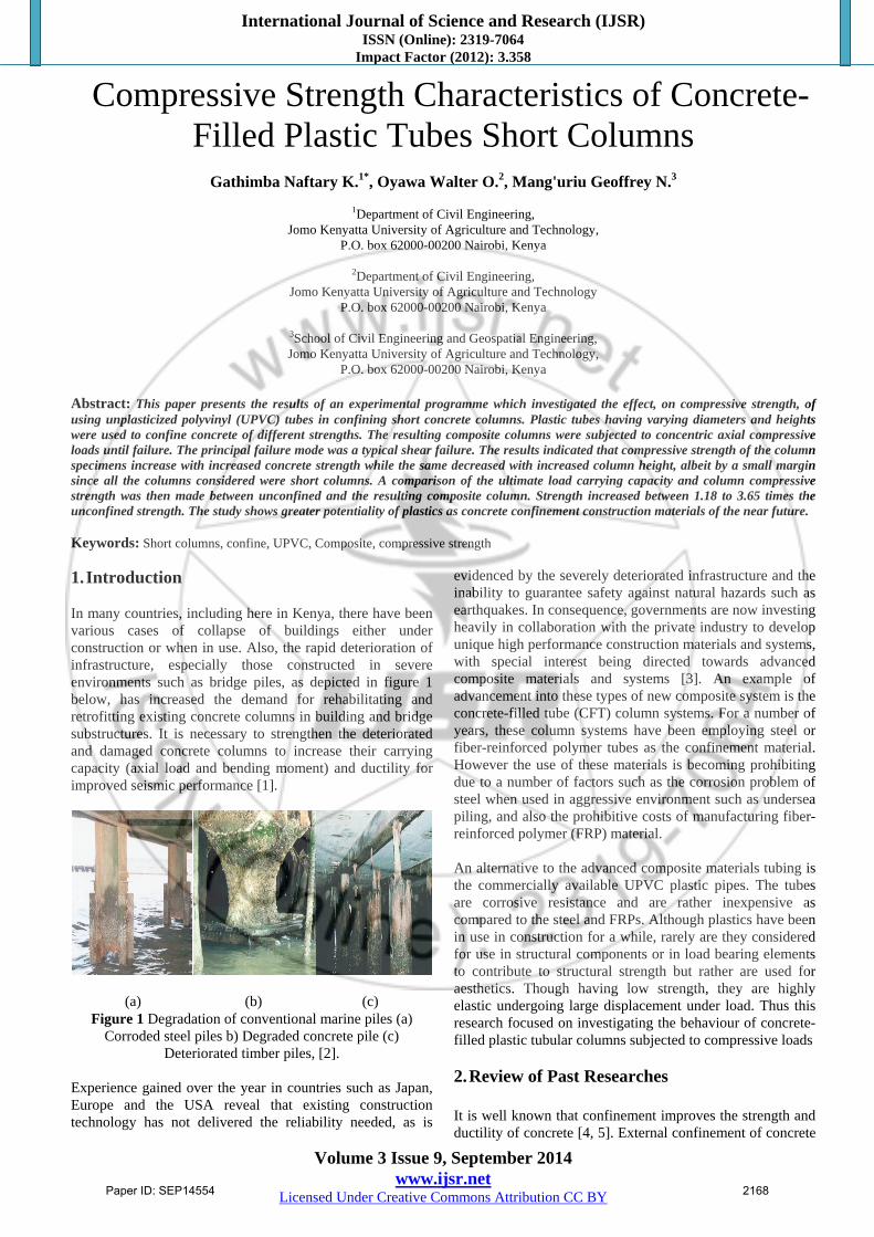
1. Introduction In many countries, including here in Kenya, there have been various cases of collapse of buildings either under construction or when in use. Also, the rapid deterioration of infrastructure, especially those constructed in severe environments such as bridge piles, as depicted in figure 1 below, has increased the demand for rehabilitating and retrofitting existing concrete columns in building and bridge substructures. It is necessary to strengthen the deteriorated and damaged concrete columns to increase their carrying capacity (axial load and bending moment) and ductility for improved seismic performance [1].
(a) (b) (c) Figure 1 Degradation of conventional marine piles (a)
Corroded steel piles b) Degraded concrete pile (c) Deteriorated timber piles, [2].
Experience gained over the year in countries such as Japan, Europe and the USA reveal that existing construction technology has not delivered the reliability needed, as is
evidenced by the severely deteriorated infrastructure and the inability to guarantee safety against natural hazards such as earthquakes. In consequence, governments are now investing heavily in collaboration with the private industry to develop unique high performance construction materials and systems, with special interest being directed towards advanced composite materials and systems [3]. An example of advancement into these types of new composite system is the concrete-filled tube (CFT) column systems. For a number of years, these column systems have been employing steel or fiber-reinforced polymer tubes as the confinement material. However the use of these materials is becoming prohibiting due to a number of factors such as the corrosion problem of steel when used in aggressive environment such as undersea piling, and also the prohibitive costs of manufacturing fiber-reinforced polymer (FRP) material. An alternative to the advanced composite materials tubing is the commercially available UPVC plastic pipes. The tubes are corrosive resistance and are rather inexpensive as compared to the steel and FRPs. Although plastics have been in use in construction for a while, rarely are they considered for use in structural components or in load bearing elements to contribute to structural strength but rather are used for aesthetics. Though having low strength, they are highly elastic undergoing large displacement under load. Thus this research focused on investigating the behaviour of concrete-filled plastic tubular columns subjected to compressive loads
2. Review of Past Researches It is well known that confinement improves the strength and ductility of concrete [4, 5]. External confinement of concrete
Paper ID: SEP14554 2168
International Journal of Science and Research (IJSR) ISSN (Online): 2319-7064
Impact Factor (2012): 3.358
Volume 3 Issue 9, September 2014 www.ijsr.net
Licensed Under Creative Commons Attribution CC BY
columns has lately been widely employed in order to enhance the strength, ductility and energy absorption capacity of the columns in construction. There has been a number of confinement mechanisms in use notably use of steel tubes and fiber reinforced polymers (FRPs). While the use of these technologies have been successful, problems such as corrosion of steel when used in aggressive environment and the high cost incurred in producing FRPs have necessitated the need for an alternative, cheaper means of confining concrete columns. Composite columns, made up of reinforced or unreinforced concrete confined with steel tubes, have been used in building construction with great efficiency for many years. Many authors have dealt with theoretical and experimental investigations on the behavior as well as the ultimate compressive strength of concrete-filled steel tube (CFST) columns. However, CFSTs are not only faced with the problem of corrosion of steel tubes but there is reduced confinement effectiveness at low levels of loading if the tube is also loaded in the axial direction due to the fact that Poisson's ratio of concrete at low levels of loading, 0.15 to 0.2 is smaller than the 0.3 value of steel [6]. Mirmiran and Shahawy, 1997 observed that the differential radial expansion of steel tube and concrete, at low levels of loading, results in partial separation between the two materials leading to a premature buckling of the tube. Thus effective confinement will only be achieved at higher loading when concrete begins to crack as it expands faster than the steel tube and becomes well confined [7]. An alternative to CFSTs is FRP composites which have been used as precast piles, girders, and pier columns [8]. As opposed to steel CFTs, Poisson's ratio of FRP tubes can be controlled through selected design of the laminate structure to provide more confinement effect [9]. The confining pressure provided by steel tubes is limited to a constant value once the tube yields, whereas FRP tubes provide a continuously increasing confining pressure, which adds to both the ultimate confined strength and ductility [10]. Advances in the field of advanced composite materials have resulted in the development of FRP sheets to confine existing concrete columns, resulting in enhanced compressive strength and ductility and improving the durability over conventional methods. Existing studies on the seismic behavior of FRP confined concrete columns have shown that FRP confinement can substantially improve the inelastic deformability of concrete columns [11]. In recent years, the compressive behavior of FRP-confined concrete has been studied extensively. Few authors have tested to-collapse concrete columns wrapped using carbon and glass fiber sheets [12, 13]. Saafi et al., [12] proved that the increase in axial stress over the confined specimen ranged from 51 to 131 percent for the concrete-filled glass tubes and 57 to 177 percent for the concrete-filled carbon tubes. However, with the high cost of advanced composite materials, the use of these materials in composite columns in light construction is not recommended. Another alternative to the advanced composite materials tubing would be the commercially available plastic uPVC sewer pipes. The strength, ductility and energy absorption capacity of new
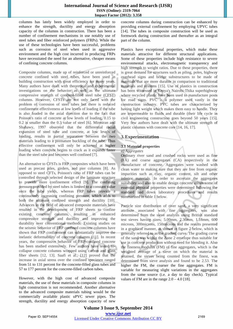
concrete columns during construction can be enhanced by providing external confinement by employing UPVC tubes [14]. The tubes in composite construction will be used as formwork during construction and thereafter as an integral part of the column. Plastics have exceptional properties, which make these materials attractive for different structural applications. Some of these properties include high resistance to severe environmental attacks, electromagnetic transparency and high strength to weight ratios. Due to these properties, there is great demand for structures such as piling, poles, highway overhead signs and bridge substructures to be made of materials that are more durable in comparison to traditional materials and systems [15]. Use of plastics in construction has been witnessed in Kenya's Nairobi-Thika superhighway where recycled plastic have been used to manufacture posts for road signs. PVC is a polymer used vastly in the construction industry. PVC tubes are characterized by having light weight which makes them easy to handle. They are impermeable to fluids and durable (their life cycle in civil engineering construction goes beyond 50 years [15]. Very few authors have dealt with the ultimate strength of plastic columns with concrete core [14, 16, 17]. 3. Experimentation 3.1 Material properties a) Aggregates Ordinary river sand and crushed rocks were used as fine (FA) and coarse aggregates (CA) respectively in the manufacture of concrete. Aggregates were washed with clean water to making sure that they are free from organic impurities such as clay, organic content, silt and other inferior materials. In order to ascertain the aggregates suitability and also to enable design concrete mixes some of essential physical properties were determined following the standard laid down laboratory procedures and results summarized in table 1 below. Particle size distribution of river sand, a very significant attribute associated with fine aggregates, was also determined from the sieve analysis using British standard test sieves having sizes; 5.00mm, 2.36mm, 1.18mm, 600 microns, 300microns, 150microns and the results presented in a graphical manner, as shown in figure 2 below, which is generally referred to as the grading curve. The grading curve of the sand was within the Zone 2 envelope thus suitable for use in concrete production without need for blending it. Also the fineness modulus (FM) of fine aggregates, which is the weighted average of a sieve on which the material is retained, the sieves being counted from the finest, was determined from sieve analysis and found to be 2.53. The higher the FM, the coarser the fine aggregates. FM is variable for measuring slight variations in the aggregates from the same source (i.e. a day to day check). Typical values of FM are in the range 2.0 – 4.0 [18].
Paper ID: SEP14554 2169
International Journal of Science and Research (IJSR) ISSN (Online): 2319-7064
Impact Factor (2012): 3.358
Volume 3 Issue 9, September 2014 www.ijsr.net
Licensed Under Creative Commons Attribution CC BY
Table 1: Summary of some physical properties of aggregates FA CA
Specific gravity on oven Dry Basis Specific gravity on saturated surface dry (SSD) Basis Apparent Specific Gravity Water absorption (%)
2.59 2.61 2.65 0.87
2.46 2.51 2.60 2.08
Figure 2: Particle size distribution for river sand (fine
aggregate) b) Cement Cement is widely used as the binder material in the concrete matrix in many applications. The cement commonly used in Kenya is categorized as 32.5or 42.5 also referred to as power plus. Cement Class 42.5 (Ordinary Portland cement) for this particular research. c) Concrete Three series of concrete grade C20, C25 and C30 were designed for use in this research work. The method of concrete mixing design applied here was in accordance to the Department of Environment of British Research Establishment (BRE), United Kingdom (1988) and the determination of various parameters necessary for the design of the mixes was based on the design tables and figures drawn from the BRE manual. The mixing of concrete was done according to the BS, ASTM and JIS procedures given in laboratory guidelines. The BRE mix design procedure from the DOE, UK was adopted for this research. A summary of the calculated mix proportions and the concrete's compressive strength, fck, at 28 days is as given in table 2 below. c) Plastic tubes. Unplasticized polyvinyl chloride (UPVC) tubes were used to confine plain concrete stub columns. UPVC pipes conforming to Kenyan standards KS ISO 3633 and KS 2079-1-2007 were procured from Masterpipe Kenya (LTD) and
Table 2: Summary of concrete mix proportions
Class of mix
Water*/cement ratio
Water* (kg/m3)
Cement (kg/m3
Sand (kg/m3)
Aggregate (kg/m3)
Compressive strength at 28
days fck, (MPa) 5/10 10/20
C20C25 C30
0.840.75 0.70
221.5213.5 210.0
265 285 310
625 615 605
420 415 410
840825 810
20.727.2 30.7
*Includes free water for cement hydration and water for absorption of aggregates to make them SSD. Agroflow irrigation systems Limited, plastic pipes manufacturing companies based in Nairobi, Kenya. 3.2 Specimen Instrumentation and Testing A total of 144 short columns (i.e. 48 column sets replicated three times, for statistics) were cast i.e. 72 unconfined and 72 UPVC-confined concrete columns. UPVC tubes with three different outer diameters: 55mm, 83mm and 110mm were used to confine concrete. The thicknesses of the tubes were 2.5mm, 3.0mm and 2.5mm respectively. The three predesigned concrete mixes namely C20, C25, and C30 were used to fill the UPVC tubes. For each class of concrete and for each diameter and height selected, three unconfined and three UPVC-confined columns having the same length were cast. To obtain unconfined conditions for a concrete column of a similar diameter as a confined column, empty UPVC tube was split on one side along the length and tied with binding wires which was then used as a mould for casting of columns. The outer plastic casing was then removed after 24 hrs, after concrete had hardened, leaving an unconfined column specimen. Typical nomenclatures for the specimen are used to designate them. For instance, C/C25/110/3 represent a confined (C) concrete column cast with concrete grade C25, having a diameter of 110mm and a slenderness ratio of 3. Freshly cast specimens were allowed to stand for 24 hrs until concrete was fully hardened. They were then marked for ease of identification then cured by covering them with sisal sacks which were wetted daily with water until the testing date. The specimens were cured for 28 days prior to testing. The experimental work was conducted utilizing compression machines at Structures and Materials laboratory of Civil Engineering department of Jomo Kenyatta University of Agriculture and Technology. The specimens were allowed to dry prior to testing. All specimens were tested up to failure under monotonic loads. The specimens were subjected to concentric axial compressive load applied at the specimens’ center by means of a hydraulic jack through uniform steel end plates to achieve a constant stress distribution at the concrete cross section. The load was applied to the entire column section. Ata El-kareim [1] in his study on behaviour of long concrete columns confined by means of plastic tubes noted that when the load was applied to the entire section, the contribution by the concrete core and tube to the total axial force was constant along the height of the column, and was not affected by the bond strength. Furthermore, Gardner & Jacobson [19] in their study on structural behaviour of
Paper ID: SEP14554 2170
International Journal of Science and Research (IJSR) ISSN (Online): 2319-7064
Impact Factor (2012): 3.358
Volume 3 Issue 9, September 2014 www.ijsr.net
Licensed Under Creative Commons Attribution CC BY
concrete filled steel tube observed that the bond strength had no influence on the structural behaviour of the column. The columns were tested using an incremental loading procedure. Load cell of 500 kN capacity was used to monitor the applied load values. Due to the extensiveness and the magnitude of sample specimens being handled in this research work, only compressive strength data is presented in this paper. The applied load was kept constant at each load stage to allow for measurements and observations. The load cell was connected to TDS 303 data logger where the results were recorded for further analysis.
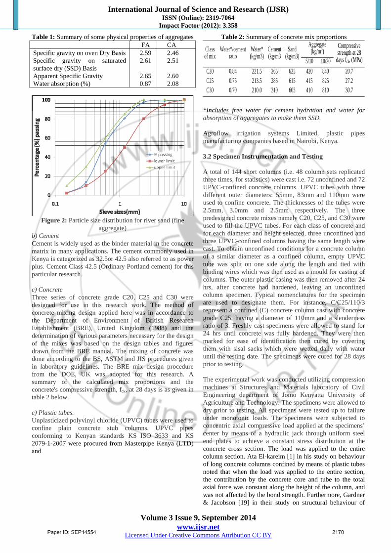
4. Results and Discussions 4.1 Observed behaviour All specimens behaved more or less in the same manner during the loading process. Sounds were heard during the early or middle stages of loading, which may be attributed to the micro cracking of the concrete. Bursting of the plastic tube was also witnessed toward the end of the loading process, for those specimens who were tested until total collapse (Figure 3(d)). It was also observed that the failure of the plastic tube was preceded by flow of resin which manifested itself by white patches at highly stressed sections (Figure 3(c)).
(a) (b) (c) (d)
Figure 3: Typical specimens' failure modes Two failure modes were observed. The principal failure mode was a typical shear failure of the plastic tube (Figure 3(a)). A typical characteristic of shear failure is that the core concrete is damaged by shear stress in one direction due to weak confinement effect of the tube. The shear crack direction can be judged by the appearance of the specimen. The same type of mode of failure was also observed by Gupta [14] and Wang & Yang [20] in their experimental program. This type of shear failure is affected by D/t ratio, and in order to avoid this type of shear failure, the ratio should be reduced, i.e., the wall thickness of the pipe should be increased. The second type of failure mode observed was bulging which lead to column specimen crushing under compression. This bulging was observed to occur either near the bottom, top or mid-height of the specimen (Figure 3(b & c)). This is a typical failure mode of short columns under pure concentric axial compressive load. At the end of the loading process, the encased concrete is totally crushed and almost pulverized. It was also observed that no concrete was attached to the remainder of the tube, and a smooth interface
was discovered. This led to the conclusion that no bond is developed between concrete and UPVC tube. 4.2 Effect of varying diameter and height on load and compressive strength of specimens Table 3 shows compressive load and strength test results for confined specimens who are presented graphically in Figures 4, 5 and 6. As expected, the load carrying capacity and the compressive strength increase with increase in the grade of concrete, as is evidenced by the results in group I through III. The graphically tabulated results show that as the diameter increases so does the load capacity, but a decrease in compressive strength. This decrease in compressive strength with increased diameter is due to the increased area with little increase in axial load carrying capacity of the columns. The anticipated increase in compressive stress with increase in pipe diameter could only be experienced when the variation or in other terms the deviation in column diameters is great to warrant column to support much greater loads as with the increased surface area and thus increased compressive stress. However, the load capacity and the compressive strength both decrease with increase in height to diameter ratio (slenderness ratio, l). In this research, however the variation is small since all the columns considered are short with a maximum l=4. It was observed that the load capacity values were in the range 54.7KN-195.3KN, while the values of compressive stress were in the range of 17 MPa-29.3 MPa. The stiffness of column specimens' increase with decrease in slenderness ratio. 4.3 Confinement effectiveness Table 4 and figure 7 reports finding on how confinement is affected by varying concrete strength, tube thickness and slenderness ratio. For an axially loaded concrete element, transversal strains are induced resulting into radial concrete expansion (Poisson's effect). Under low loading conditions, the transverse strains are proportional to longitudinal strain, and associated by the Poisson's coefficient which for concrete usually varies between 0.15 to 0.25. After reaching a certain critical stress (typically between 60% and 80% of the concrete strength), micro-cracking formation occurs in concrete, transversal strains increases quickly leading to large transversal strains for relatively small longitudinal strain. These micro-cracks evolve to macro-cracks that eventually lead to concrete rapture with cracks parallel to the loading. This rupture of concrete can be delayed by confining the concrete appropriately. The confinement mechanism of concrete is related to the use of materials that provides tensile strength to restrict this increase in transversal strain. The effect of confinement of concrete at high levels of loading leads to a triaxial compression stress state in concrete, which provide a superior behaviour in both strength and ductility than concrete which is uniaxially compressed. Concrete columns can be confined by: Lateral reinforcement in the form of steel ties or spirals; Encasing concrete in steel tubes; External fiber composite wraps; Encasing concrete in fiber composite tubes; or Encasing concrete in plastic tubes (a new technology). All these means of confinement produce a so-called ‘passive’ state of confinement, in which the confining effect is a function of the lateral expansion of the concrete core.
Paper ID: SEP14554 2171

International Journal of Science and Research (IJSR) ISSN (Online): 2319-7064
Impact Factor (2012): 3.358
Volume 3 Issue 9, September 2014 www.ijsr.net
Licensed Under Creative Commons Attribution CC BY
Table 3: Specimen details and compressive load and strength test results for confined specimens only
Sample. No
Column Series Designation
Column specimens dimensions (mm)
Slenderness (h/D) ratio
Average load (kN)
Average strength (N/mm2)
Outer diameter,
D
Height, h
Tube thickness,
t
GROUP I
C/C20/110/2 110
220 2.5
2 167.3 17.6
C/C20/110/3 330 3 161.8 17.0
C/C20/83/2
83
166
3.0
2 131.1 24.2
C/C20/83/3 249 3 121.9 22.5
C/C20/83/4 332 4 119.7 22.1
C/C20/55/2
55
110
2.5
2 60.1 25.3
C/C20/55/3 165 3 58.8 24.7
C/C20/55/4 220 4 54.7 23.0
GROUP II
C/C25/110/2 110
220 2.5
2 181.3 19.1
C/C25/110/3 330 3 171.8 18.1
C/C25/83/2
83
166
3.0
2 140.6 26.0
C/C25/83/3 249 3 133.2 24.6
C/C25/83/4 332 4 130.2 24.1
C/C25/55/2
55
110
2.5
2 67.5 28.4
C/C25/55/3 165 3 64.0 26.9
C/C25/55/4 220 4 55.1 23.2
GROUP III
C/C30/110/2 110
220 2.5
2 195.3 20.5
C/C30/110/3 330 3 180.2 19.0
C/C30/83/2
83
166
3.0
2 144.8 26.8
C/C30/83/3 249 3 135.5 25.0
C/C30/83/4 332 4 132.5 24.5
C/C30/55/2
55
110
2.5
2 69.6 29.3
C/C30/55/3 165 3 66.0 27.8
C/C30/55/4 220 4 62.6 26.3
Figures 4, 5, 6: Variation of Load capacity, Pult, and compressive strength, fcc, with change in concrete strength, diameter and
heights for UPVC-concrete confined columns
Paper ID: SEP14554 2172
International Journal of Science and Research (IJSR) ISSN (Online): 2319-7064
Impact Factor (2012): 3.358
Volume 3 Issue 9, September 2014 www.ijsr.net
Licensed Under Creative Commons Attribution CC BY
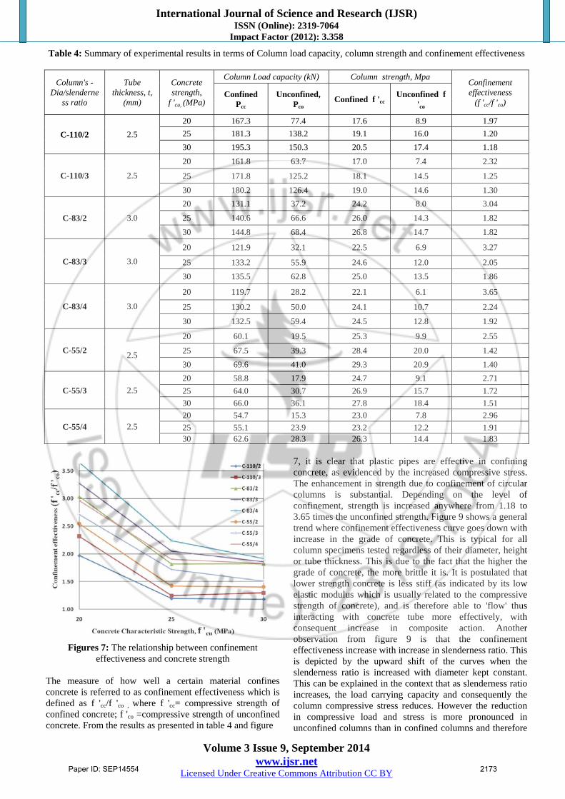
Table 4: Summary of experimental results in terms of Column load capacity, column strength and confinement effectiveness
Column's -Dia/slenderne
ss ratio
Tube thickness, t,
(mm)
Concrete strength,
f 'cu, (MPa)
Column Load capacity (kN) Column strength, Mpa Confinement effectiveness
(f 'cc/f 'co) Confined
Pcc Unconfined,
Pco Confined f 'cc
Unconfined f 'co
C-110/2 2.5
20 167.3 77.4 17.6 8.9 1.97
25 181.3 138.2 19.1 16.0 1.20
30 195.3 150.3 20.5 17.4 1.18
C-110/3 2.5
20 161.8 63.7 17.0 7.4 2.32
25 171.8 125.2 18.1 14.5 1.25
30 180.2 126.4 19.0 14.6 1.30
C-83/2 3.0
20 131.1 37.2 24.2 8.0 3.04
25 140.6 66.6 26.0 14.3 1.82
30 144.8 68.4 26.8 14.7 1.82
C-83/3 3.0
20 121.9 32.1 22.5 6.9 3.27
25 133.2 55.9 24.6 12.0 2.05
30 135.5 62.8 25.0 13.5 1.86
C-83/4 3.0
20 119.7 28.2 22.1 6.1 3.65
25 130.2 50.0 24.1 10.7 2.24
30 132.5 59.4 24.5 12.8 1.92
C-55/2
2.5
20 60.1 19.5 25.3 9.9 2.55
25 67.5 39.3 28.4 20.0 1.42
30 69.6 41.0 29.3 20.9 1.40
C-55/3 2.5
20 58.8 17.9 24.7 9.1 2.71
25 64.0 30.7 26.9 15.7 1.72
30 66.0 36.1 27.8 18.4 1.51
C-55/4 2.5 20 54.7 15.3 23.0 7.8 2.96
25 55.1 23.9 23.2 12.2 1.91 30 62.6 28.3 26.3 14.4 1.83
Figures 7: The relationship between confinement
effectiveness and concrete strength The measure of how well a certain material confines concrete is referred to as confinement effectiveness which is defined as f 'cc/f 'co , where f 'cc= compressive strength of confined concrete; f 'co =compressive strength of unconfined concrete. From the results as presented in table 4 and figure
7, it is clear that plastic pipes are effective in confining concrete, as evidenced by the increased compressive stress. The enhancement in strength due to confinement of circular columns is substantial. Depending on the level of confinement, strength is increased anywhere from 1.18 to 3.65 times the unconfined strength. Figure 9 shows a general trend where confinement effectiveness curve goes down with increase in the grade of concrete. This is typical for all column specimens tested regardless of their diameter, height or tube thickness. This is due to the fact that the higher the grade of concrete, the more brittle it is. It is postulated that lower strength concrete is less stiff (as indicated by its low elastic modulus which is usually related to the compressive strength of concrete), and is therefore able to 'flow' thus interacting with concrete tube more effectively, with consequent increase in composite action. Another observation from figure 9 is that the confinement effectiveness increase with increase in slenderness ratio. This is depicted by the upward shift of the curves when the slenderness ratio is increased with diameter kept constant. This can be explained in the context that as slenderness ratio increases, the load carrying capacity and consequently the column compressive stress reduces. However the reduction in compressive load and stress is more pronounced in unconfined columns than in confined columns and therefore
Paper ID: SEP14554 2173
International Journal of Science and Research (IJSR) ISSN (Online): 2319-7064
Impact Factor (2012): 3.358
Volume 3 Issue 9, September 2014 www.ijsr.net
Licensed Under Creative Commons Attribution CC BY
the ratio of the stresses will he higher for longer columns due to the greater difference in stress than for short columns. A notable observation is how the confinement effect for the 83mm-diameter columns set was higher than the other column. This is attributed to the fact that the tube thickness was higher (3.0mm) as compared to the other columns (2.5mm). 5. Conclusion and Recommendations This paper reports the results of an experimental programme which investigated the effect, on compressive strength, of using unplasticized polyvinyl (UPVC) tubes in confining short concrete columns. It was found out that plastic pipes are effective in confining concrete, as evidenced by the increased compressive stress. The enhancement in strength due to confinement of circular columns is substantial and depending on the level of confinement, strength is increased anywhere from 1.18 to 3.65 times the unconfined strength values. It was evident that confinement effectiveness is dependent on the strength of concrete where the former reduces with the increase of the concrete strength due to the brittle behaviour of high strength concrete. Low strength concrete tends to be more ductile suggesting the potential of an earthquake resistant composite column system. The tube thickness also affects the confinement effect of the plastic tubes and this research recommends that further research should be conducted with varying tube thicknesses to establish the actual contribution it makes in column confinements. References [1] Ata El-kareim Shoeib Soliman, (2011). “Behavior of
long confined concrete column.” Ain Shams Engineering Journal, 2, 141-148.
[2] Iskander, M. G., and Stachula, A. (1999) "FRP Composite Polymer Piling: An Alternative to Timer Pilling for Water-Front Applications." Geotechnical News, 4(Dec):27-29.
[3] Oyawa W. O., Sugiura K. & Watanabe E. (1998). “Elasto-plastic behaviour of axially loaded filled circular steel stub columns.” J. Struct. Engrg., JSCE, 44(A), 147-158.
[4] Ahmad, S.H. and S. P. Shah, 1982. “Complete Triaxial Stress-Strain Curves for Concrete, Journal of Structural Division,” Proceedings of the American Society of Civil Engineering, ASCE,108(ST4):728-742.
[5] Mander, J.B., M.J. N. Priestley and R. Park. 1988. “Theoretical Stress-Strain Model for Confined Concrete,” Journal of Structural Engineering, ASCE, 114:1804-1823.
[6] Wei, S., Mau, S. T., and Mantrala, S. K. "Performance of New Sandwich Tube under Axial Loading: Experiment", Journal of Structural Engineering, Vol. 121, No. 12, Dec. 1995, pp. 1806-1821.
[7] Ivan M. (1997), “Composite columns in composite construction design for buildings,” ASCE, Mc Graw-Hill, New York, 4.1-4.5.1
[8] V. M. Karbhari, J. W. Chin, D. Hunston. B. Benmokrane, T. Juska, R. Morgan, J. J. Lesko, U. Sorathia and D. Reynaud, (2003) “Durability Gap
Analysis for Fiber-Reinforced Polymer Composites in Civil Infrastructure,” Journal of composites for construction, 7(3), 238-247, 2003.
[9] Shahawy, M., and Mirmiran, A. "Hybrid FRP-Concrete Beam-Columns", Proc. of ICCEI5 Fifth International Conference on Composites Engineering, Las Vegas, July 5-11, 1998, pp. 619-620.
[10] Michel Sabri Samaan, (1997). “An analytical and experimental investigation of concrete-filled fiber reinforced plastics (FRP) tubes” PhD thesis, University of Central Florida, Orlando, Florida.
[11] Ozbakkaloglu, T., and Saatcioglu, M. 2007. Seismic Performance of Square High-Strength Concrete Columns in FRP Stay-in-place Formwork. Journal of Structural Engineering-ASCE, 133(1), 44-56.
[12] Saafi, M., Toutanji, H., and Li, Z. 1999, Behavior of concrete columns confined with fiber reinforced polymer tubes, ACI Mat. Journal, 96(4):500–509.
[13] Toutanji, H.A. 1999, Stress–strain characteristics of concrete columns externally confined with advanced fiber composite sheets, ACI Mat. Jour., 96(3): 397–404.
[14] Gupta, (2013):“Confinement of concrete columns with Unplasticized Poly-vinyl chloride tubes.” International Journal of Advanced Structural Engineering, Aug 2013. Available online at: http://www.advancedstructeng.com/content/5/1/19
[15] M. Marzouck & K. Sennah, (2002). Concrete-filled PVC tubes as compression members: Composite Materials in Concrete Construction. Proceedings of the international congress “challenges of concrete construction” 31-38
[16] Daniali, S., (1992) "Investigation of the behavior of reinforced plastic columns with concrete core." Proc., ASCE 1992 Material Congress, 666-676
[17] Carl E. Kurt, (1978). “Concrete filled structural plastic columns.” Journal of the Structural Division, 104(1) January 1978, 55-63
[18] Neville Adam M., (2011). “Properties of concrete”-- 5th edition, ISBN 978-0-273-75580-7.
[19] Gardner NJ, Jacobson ER. Structural behavior of concrete filled steel tube. ACI J, 1976:404–13.
[20] Wang J, Yang Q (2010) Experimental study on Mechanical Properties of concrete confined with plastic Pipe. Title no. 107-M17. ACI Mater J: 107,132–137
Paper ID: SEP14554 2174