Compression Behavior of Fluted-Core Composite Panels · Compression Behavior of Fluted-Core...
16
1 American Institute of Aeronautics and Astronautics Compression Behavior of Fluted-Core Composite Panels Marc R. Schultz 1 NASA Langley Research Center, Hampton, VA 23681-2199, USA Leonard Oremont 2 Lockheed Martin Corporation, Hampton, VA 23681-2199, USA J. Carlos Guzman 3 and Douglas McCarville 4 The Boeing Company, Seattle, WA 98124-2207, USA Cheryl A. Rose 5 and Mark W. Hilburger 5 NASA Langley Research Center, Hampton, VA 23681-2199, USA In recent years, fiber-reinforced composites have become more accepted for aerospace applications. Specifically, during NASA’s recent efforts to develop new launch vehicles, composite materials were considered and baselined for a number of structures. Because of mass and stiffness requirements, sandwich composites are often selected for many applications. However, there are a number of manufacturing and in-service concerns associated with traditional honeycomb-core sandwich composites that in certain instances may be alleviated through the use of other core materials or construction methods. Fluted- core, which consists of integral angled web members with structural radius fillers spaced between laminate face sheets, is one such construction alternative and is considered herein. Two different fluted-core designs were considered: a subscale design and a full-scale design sized for a heavy-lift-launch-vehicle interstage. In particular, axial compression of fluted- core composites was evaluated with experiments and finite-element analyses (FEA); axial compression is the primary loading condition in dry launch-vehicle barrel sections. Detailed finite-element models were developed to represent all components of the fluted-core construction, and geometrically nonlinear analyses were conducted to predict both buckling and material failures. Good agreement was obtained between test data and analyses, for both local buckling and ultimate material failure. Though the local buckling events are not catastrophic, the resulting deformations contribute to material failures. Consequently, an important observation is that the material failure loads and modes would not be captured by either linear analyses or nonlinear smeared-shell analyses. Compression-after-impact (CAI) performance of fluted–core composites was also investigated by experimentally testing samples impacted with 6 ft.-lb. impact energies. It was found that such impacts reduced the ultimate load carrying capability by approximately 40% on the subscale test articles and by less than 20% on the full-scale test articles. Nondestructive inspection of the damage zones indicated that the detectable damage was limited to no more than one flute on either side of any given impact. More study is needed, but this may indicate that an inherent damage- arrest capability of fluted core could provide benefits over traditional sandwich designs in certain weight-critical applications. 1 Aerospace Engineer, Structural Mechanics and Concepts Branch, Mail Stop 190, AIAA Senior Member. 2 Aeronautical Engineer, NASA Langley Research Center, Mail Stop 460. 3 Manufacturing Research and Development Engineer, Boeing Research & Technology, P.O. Box 3707, Mail Stop 4R-05 4 Manufacturing Research and Development Technical Fellow, Boeing Research & Technology, P.O. Box 3707, Mail Stop 4R-05 5 Senior Aerospace Engineer, Structural Mechanics and Concepts Branch, Mail Stop 190, AIAA Senior Member. https://ntrs.nasa.gov/search.jsp?R=20110010005 2018-06-28T13:40:56+00:00Z
Transcript of Compression Behavior of Fluted-Core Composite Panels · Compression Behavior of Fluted-Core...

1
American Institute of Aeronautics and Astronautics
Compression Behavior of Fluted-Core Composite Panels
Marc R. Schultz1
NASA Langley Research Center, Hampton, VA 23681-2199, USA
Leonard Oremont2
Lockheed Martin Corporation, Hampton, VA 23681-2199, USA
J. Carlos Guzman3 and Douglas McCarville
4
The Boeing Company, Seattle, WA 98124-2207, USA
Cheryl A. Rose5 and Mark W. Hilburger
5
NASA Langley Research Center, Hampton, VA 23681-2199, USA
In recent years, fiber-reinforced composites have become more accepted for aerospace
applications. Specifically, during NASA’s recent efforts to develop new launch vehicles,
composite materials were considered and baselined for a number of structures. Because of
mass and stiffness requirements, sandwich composites are often selected for many
applications. However, there are a number of manufacturing and in-service concerns
associated with traditional honeycomb-core sandwich composites that in certain instances
may be alleviated through the use of other core materials or construction methods. Fluted-
core, which consists of integral angled web members with structural radius fillers spaced
between laminate face sheets, is one such construction alternative and is considered herein.
Two different fluted-core designs were considered: a subscale design and a full-scale design
sized for a heavy-lift-launch-vehicle interstage. In particular, axial compression of fluted-
core composites was evaluated with experiments and finite-element analyses (FEA); axial
compression is the primary loading condition in dry launch-vehicle barrel sections. Detailed
finite-element models were developed to represent all components of the fluted-core
construction, and geometrically nonlinear analyses were conducted to predict both buckling
and material failures. Good agreement was obtained between test data and analyses, for
both local buckling and ultimate material failure. Though the local buckling events are not
catastrophic, the resulting deformations contribute to material failures. Consequently, an
important observation is that the material failure loads and modes would not be captured by
either linear analyses or nonlinear smeared-shell analyses. Compression-after-impact (CAI)
performance of fluted–core composites was also investigated by experimentally testing
samples impacted with 6 ft.-lb. impact energies. It was found that such impacts reduced the
ultimate load carrying capability by approximately 40% on the subscale test articles and by
less than 20% on the full-scale test articles. Nondestructive inspection of the damage zones
indicated that the detectable damage was limited to no more than one flute on either side of
any given impact. More study is needed, but this may indicate that an inherent damage-
arrest capability of fluted core could provide benefits over traditional sandwich designs in
certain weight-critical applications.
1 Aerospace Engineer, Structural Mechanics and Concepts Branch, Mail Stop 190, AIAA Senior Member.
2 Aeronautical Engineer, NASA Langley Research Center, Mail Stop 460.
3 Manufacturing Research and Development Engineer, Boeing Research & Technology, P.O. Box 3707,
Mail Stop 4R-05 4 Manufacturing Research and Development Technical Fellow, Boeing Research & Technology, P.O. Box 3707,
Mail Stop 4R-05 5 Senior Aerospace Engineer, Structural Mechanics and Concepts Branch, Mail Stop 190, AIAA Senior Member.
https://ntrs.nasa.gov/search.jsp?R=20110010005 2018-06-28T13:40:56+00:00Z

2
American Institute of Aeronautics and Astronautics
I. Introduction
n recent years, fiber-reinforced composite structures have become more accepted for many different applications,
including aerospace vehicles. When properly applied, composite structures can have many benefits over
traditional metallic structures, including lower mass, better fatigue resistance, lower part count, and reduced life-
cycle cost. During NASA’s recent efforts to develop new launch vehicles, composite materials were considered and
baselined for a number of structures. Specifically, several of the primary dry shell components such as intertanks
and interstages were baselined as composite (see for example, refs. 1 and 2). Various shell designs and construction
methods were considered including several composite sandwich shells. Because they possess a low-density core and
a high bending stiffness, sandwich shells can be very structurally efficient for applications where the structure is
prone to buckling or requires high bending stiffness. Traditional composite sandwich panels are composed of inner
and outer facesheets separated by a core material such as balsa wood, polymeric foam, or honeycomb. These
facesheets and core are typically joined with film adhesive in either a co-cure (with green facesheets) or a hot-bond
(with pre-cured facesheets) operation. Once joined, the facesheets carry tension and compression loads, and the core
keeps the facesheets separated while carrying the through-thickness shear loads. Though structurally efficient,
traditional composite sandwich structures can have manufacturing and in-service drawbacks. To address some of
these shortcomings, alternative sandwich-type structural concepts are being developed. One such structural concept
is manifested in fluted-core composite structures (sandwich-like structures that consist of integral angled web
members and structural radius fillers spaced between laminate face sheets, see Fig. 1). Fluted-core and similar
designs, such as corrugated-core, are not new and have been explored previously through experiment and analysis.3-9
Fluted- and corrugated-core structures have also been proposed and/or used on a limited number of aerospace
structures.10-13
However, a better understanding of the behavior and failure mechanisms of different fluted-core-
composite designs and construction methods is needed if they are to be incorporated into a wider variety of large
weight-critical applications. Different applications will drive different requirements, so perceived benefits and
drawbacks for honeycomb-core and fluted-core composites are discussed in section II.
The primary loading condition in dry launch-vehicle cylindrical-shell sections is axial compression. The current
paper details an effort to better understand the compression behavior and failure modes of fluted-core composite
structures through a combination of experimental testing and detailed finite-element analysis (FEA). Two different
fluted-core designs were considered: a subscale cross section and a full-scale cross section representative of a design
required for the interstage of a heavy-lift launch vehicle. The current analytical and experimental effort is intended
to investigate localized compression failures, as opposed to global failures such as Euler buckling. As such, FEA
was used to design the test articles and predict behavior under load. Subsequently, samples representing both cross-
sections were tested in pristine and impact-damaged states. Impacted test articles were tested to provide preliminary
data on the impact damage resistance and tolerance of fluted-core composites.
Perceived advantages and disadvantages of fluted-core composites in comparison with honeycomb-core
composites are discussed in section II. The test articles are described in section III, and the finite-element modeling
and analysis approach used for the pretest predictions is described in section IV. The pretest predictions and the
experimental results, including impacted test articles, are discussed in section V. The paper ends with concluding
remarks in section VI.
II. Honeycomb-Core Composites vs. Fluted-Core Composites
Honeycomb core is a mature product that can be procured in a wide variety of metallic and nonmetallic material
and form combinations (e.g., aluminum flex cell and fiberglass/fiberglass hexagonal cell). Moreover, honeycomb
I
(a) Full scale (b) Subscale
Figure 1. Cross-sectional geometries of full-scale and subscale specimens, and nomenclature.
Noodle Short Span
Long spanFlute
Facesheets
Web

3
American Institute of Aeronautics and Astronautics
core is used to produce sandwich components in numerous industries. For example, honeycomb-core composites are
used for engine nacelles in the aerospace industry, for hulls in the marine industry, and for snow boards in the
sporting goods industry. Still, honeycomb-core sandwich construction has manufacturing and in-service issues that
lead to design knockdown factors.14
A number of these issues are listed below.
Manufacturing issues for honeycomb-core composites:
1) It is imperative that the facesheet-to-core bond layer be somewhat elastic and free of porosity, voids, and/or
disbonds. However, traditional nondestructive inspection (NDI) methods can not accurately determine the
facesheet-to-core bond integrity.
2) Typically, the facesheet-to-core bond layer functions best if filleting between the core cell walls and the
facesheets is achieved. This may or may not happen depending on adhesive resin flow and the bag cure
environment.
3) Individual core pieces, which are typically limited to roughly 4 ft. x 8 ft., must be 100% bonded together
with foaming or potting adhesives to insure continuous through-thickness shear capability. If any
discontinuities in the bond (either core to core or core to facesheet) occur, the overall strength of the panel
may be reduced.
4) Co-cured honeycomb-core panels can suffer from facesheet dimpling and/or pillowing if the facesheets are
thin, the core cell size is large, or a high bond pressure is used. The resulting fiber waviness can
significantly reduce facesheet in-plane properties. In practice, the facesheet-to-honeycomb bond is done at
relatively low pressures (45 psi) to reduce the facesheet dimpling and pillowing. However, curing the
facesheets at low pressures under and over the core can result in laminates with higher porosity and hence
lower in-plane properties than would be achieved when using standard 85 to 100 psi cure pressures.
5) Low-density core is susceptible to crushing during autoclave bond, especially in ramped areas. This may
limit usable bond pressures and require additional bagging features such as edge bars and grip strips.
6) Nonmetallic honeycomb cores are susceptible to moisture absorption prior to bond and in service. If the
core is not properly dried prior to bond this moisture can cause a blow out in the core or induce porosity in
the film adhesive or facesheets.
7) Honeycomb-core node bonds can break during forming or fatigue loading.
In-service issues for honeycomb-core composites:
1) Aluminum core can galvanically corrode if it is placed in contact with carbon-reinforced composites.
2) Metallic cores can corrode in the presence of trapped moisture.
3) Low-velocity impacts can create facesheet-to-core disbonds that are not readily detectable during visual
inspection.
4) Honeycomb-to-facesheet bonds do not have any inherent crack-arrest features.
5) Trapped moisture arising from exposed edges, facesheet punctures, or ingression through thin face sheets
can break down core-to-facesheet bonds and core node bonds. This breakdown can be accelerated on
aerospace components that are subjected to repeated freeze-thaw cycles.
6) As the core absorbs moisture, the weight and strength of the panel increases and decreases, respectively.
Design knockdowns must be used to account for these long-term issues.
Fluted-core structures, especially those fabricated with composite materials, have a more limited history. Various
designs (e.g., corrugated web, canted I-beams, and tubes) have been considered and have been made by a variety of
manufacturing methods (e.g., co-cure, co-bond, hot bond, and liquid molding). These alternatives have different
manufacturing and technology readiness levels (MRL and TRL) and hence different applicability to dry shell
structures such as intertanks and interstages. It is believed that the manufacturing methods used to fabricate the test
articles discussed herein are low cost and repeatable enough to build extremely large (30-ft.-diameter, 100-ft.-long)
high-performance structures. Manufacturing and in-service issues associated with fluted-core composites are listed
below.15
Manufacturing issues for fluted-core composites:
1) Because of the large variety of designs and manufacturing methods envisioned for fluted-core panels and
the relatively small number that have been placed into production, any given design and manufacturing
combination may have only limited structural test data associated with it, and may therefore require a
lengthy development and certification process.

4
American Institute of Aeronautics and Astronautics
2) In order to create continuous load-carrying capability, a large number of fluted-core members must be
fabricated and joined with minimal defects; this suggests a high degree of automation and new generation,
perhaps costly, equipment and facilities may be required.
3) The facesheets of a fluted-core panel can be inspected using standard pulse echo methods, but the flute
walls are harder to see and may require time consuming special inspection methods.
In-service issues for fluted-core composites:
1) There exist limited in-service data for any particular fluted-core design and manufacturing combination.
Even for properties that may be considered potentially advantageous (e.g., damage arresting, and
moisture/vapor purging capabilities) there may be no in-service data to corroborate estimations.
Since fluted-core composites consist of laminate layers preferentially located at desired angles, they can be cured
at high pressures (85-100 psi). These pressures help to minimize porosity and maximize in-plane properties. Unlike
honeycomb core, which has directional properties (e.g., the through-thickness shear capability in the transverse
direction is typically about half that of the longitudinal, or ribbon direction) that can only be changed in available
stepwise density increments, fluted core can be tailored in more ways. Among the fluted-core variables that can be
changed to obtain desired properties are the flute height and width, the angle of the web, the web material and layup,
the fillet (noodle region) material, and the size of the fillet region.
In summary, there are advantages and disadvantages to both honeycomb-core and fluted-core composites that
suggest the use of one or the other in a particular application. Among the advantages of honeycomb core are that it is
lightweight, mature, low cost, and there are many varieties available. Some disadvantages of honeycomb-core are
that it is vulnerable to moisture, it has low damage tolerance, and the facesheets can have reduced (compared to
laminates cured at higher pressures on solid tools) in-plane properties. Advantages of fluted-core over honeycomb
core include that it can, in certain instances, be designed to be lighter weight, there are no significant permeability
issues, it can have more options for tailoring, and it may have inherent damage containment capability. However,
there is much less aerospace experience with fluted core than honeycomb core, and in general fluted core is more
costly to fabricate. Still, because of potential fluted-core benefits compared to other sandwich-like structures, it is
important to develop a better understanding of its performance under different loading conditions so that fair
comparisons and trade studies can be undertaken.
III. Test Article Description
The two test-article cross sections considered in this paper are shown in Fig. 1. The subscale test articles were
0.74-in. thick and consisted of five flutes. The full-scale test articles were designed with a cross section
representative of that required for a heavy-lift-launch-vehicle interstage, and were 1.6-in. thick and consisted of
three flutes. All test articles were fabricated by wrapping unidirectional 350- F toughened carbon-epoxy prepreg
plies around trapezoidal mandrels, arranging the wrapped mandrels with pultruded unidirectional-prepreg radius
fillers (noodles), and placing prepreg facesheets on top of and below the wrapped mandrels. The entire arrangement
was then autoclave co-cured and the mandrels were removed after cure. For the subscale cross section, the total web
layup was [±45/±45]T and the total facesheet layup (including the plies originally wrapped around the mandrel) was
[±45/0/90]S. (Note: The coordinate systems for describing the layouts use 0-degree as the long, axial test-article
direction, 90-degree in plane and perpendicular to the 0-degree directions, and normals as shown by the red arrows
in Fig. 1.) For the full-scale cross section, the total web layup was [45/0/90/90/0/45]T and the total facesheet
layup (including the plies wrapped around the mandrel) was [45/0/90/45/0/902/0/45/90/0/45]T.
Eight test articles are discussed in this paper. Of these, four test articles had the subscale cross section and four
had the full-scale cross section. In both of these groups, half were tested in a pristine condition and half were tested
after being subjected to a 6 ft.-lb. impact from a ½-in.-diameter spherical indenter. Each of these test articles had
electrical-resistance strain gages applied at locations predicted to experience local buckling. Further, they were
painted with a black-and-white speckle pattern to enable full-field optical displacement and strain measurements
using the video image correlation system VIC-3D.16
The subscale test articles (Fig. 2a) had a total length of 11 in. with 1.5-in.-long by 0.125-in.-thick fiberglass tabs
applied to both faces at each end. As shown, these tabs had a 45-degree bevel that tapered into the test article.
Additionally, 1 in. on both ends was potted into a steel frame using epoxy grout. Considering the tabs and potting,
the test length of the subscale test articles was 8 in. The subscale test articles were approximately 5.75-in. wide on
the wide face and 5.25-in. wide on the narrow face. The full-scale test articles (Fig. 2b) had a total length of 9.375
in., with 1 in. potted at either end. The full-scale test articles did not have tabs so the test length of the full-scale test

5
American Institute of Aeronautics and Astronautics
articles was 7.375 in. The full-scale test articles were 5.50-in. wide on the wide face and 3.875-in. wide on the
narrow face. For both the subscale and full-scale test articles, the wide face was termed the front, and the narrow
face was termed the back. To prepare the test articles for testing, all edges were machined flat and parallel, or flat
and perpendicular.
IV. Finite-Element Modeling and Analysis Approach
The compression response of fluted-core components has a number of complexities that can make either
smeared-shell or linear analyses insufficient for predicting failure. In particular, local buckling can occur in the
facesheets and webs before any material failures or global-buckling events. Even if not catastrophic by themselves,
these local buckling responses must be captured because they may lead to other failures in the postbuckled range of
loading. Smeared-shell analyses are not capable of capturing these local-buckling responses. Geometrically
nonlinear analyses that capture enough of the cross-sectional detail are needed to predict the failures that occur in
the postbuckled range. Care is required in developing finite-element models that can accurately capture this complex
behavior.
The finite-element models used in this study were built using MSC.Patran 2010,17
the analyses were performed
using Abaqus/Standard 6.9.1,18
and the post processing was done using Abaqus/CAE 6.9.1.19
In order to account for
important details in a computationally efficient manner, and to facilitate ease in post processing, the facesheets,
flutes, and noodles were modeled using separate element sets. As shown in Fig. 3, these element sets were combined
to create the full finite element model. In the fluted-core test articles discussed herein, each pultruded noodle was
surrounded by either the top or the bottom facesheet on the outside, and the flutes on the inside as shown in Fig. 4a.
The facesheets and the flutes have a thickness dimension that was much smaller than the other physical dimensions,
and were modeled with Abaqus S4R5 shell elements (Figs. 3a and 3b). However, the small noodle dimensions were
not very small compared to the cross-sectional dimensions of the fluted-core test articles, so the noodles were
modeled with Abaqus C3D6 six-noded, three-dimensional solid wedge elements (Fig. 3c). Fig. 4b shows details of
the finite element modeling in the vicinity of a noodle, and is used to describe how the element sets were connected.
As can be seen in the figure, the nodal reference surfaces lie along four distinct interfaces regions; 1) the mid-plane
of the flute web that is formed by the plies from adjacent flutes, 2) the inner surface of the facesheets adjacent to the
flute plies, 3) the outer surface of the noodle adjacent to the flute web plies, and 4) the outer surface of the noodle
adjacent to the facesheets. The element sets along each of these interface regions are connected through shared
nodes, resulting in coincident shell elements in regions 1 and 2, and shell elements coincident with a solid element
face in regions 3 and 4. Offsets were applied to the facesheet and flute element sets to ensure that plies were located
(a) Subscale (b) Full scale
Figure 2. Test articles.

6
American Institute of Aeronautics and Astronautics
properly with respect to the nodal reference surfaces. Constructing the model in this manner ensured that the stresses
and strains in the facesheets, flutes, and noodles could be easily separated during post processing of the results,
while at the same time fostering computational efficiency by using the fewest possible nodes.
In order to be able to correctly define the material properties in the individual components, separate coordinate
systems were used for each curved and each straight section of the flutes and the noodles. Each flute thus required
four cylindrical coordinate systems (one for each corner) and three rectangular coordinate systems for the straight
sections. One rectangular coordinate system was shared with the two facesheets and all the noodles, and each web
had a rectangular coordinate system that was shared with the adjacent flutes. A full set of material properties was not
available for the specific toughened carbon-epoxy used in the construction of the test articles, so linear material
properties for the similar material IM7/8552 were used in the modeling of all components.20
Compressive material
properties were used for the plies expected to be subjected to fiber-direction compression and tensile material
properties were used for those plies expected to be subjected to fiber-direction tension.
To be consistent with the test articles, the fiberglass tabs were modeled for the subscale test articles, and the
potted ends were modeled for both the subscale and full-scale test articles. Including the potted and tabbed regions
enabled the prediction of effective axial stiffness and direct comparison of the axial shortening with the
experimental test results. The tabs were modeled using an extra set of elements with appropriate offsets that shared
(a) The flutes modeled with shell elements. (b) The facesheets modeled with shell elements.
(c) The noodles modeled with 3D solid elements. (d) The shell and solid elements combined.
Figure 3. Finite-element model of the subscale test articles showing the separate meshes for the flutes, the
facesheets, the noodles, and all meshes combined.

7
American Institute of Aeronautics and Astronautics
nodes at the interface with the adjacent facesheet elements, therefore adding no additional degrees of freedom The
potting constraint was simulated by setting both transverse displacements to zero on all the nodes of elements within
the potted region. Except for those nodes at the very ends of the panels, the axial displacements were unconstrained
on the nodes in the potted region. To simulate the constraint of the loading platens used in the experiments, the
nodes at the very ends of the panels were forced to remain in a plane that was prevented from rotating. Because the
modeling approach was slightly refined between models, this was accomplished using different, but essentially
equivalent, methods in the subscale and the full-scale models. On each end of the subscale model, the nodes were
tied using multiple point constraints (MPCs). These MPCs fixed the dependent nodes to an extra independent node
located at the cross-sectional center of each end. On the bottom of the test article, the center node was fixed in all
displacements and rotations. On the top, the extra node was fixed in all rotations and in the transverse directions, but
was allowed to move in the axial or loading direction. A point force, compressing the article in the axial direction,
was then applied to this top center node to simulate the test conditions on the physical test articles. This was the only
load applied to the system; the center bottom node provided a reaction force equal in magnitude to the applied load.
For the full-scale model, the nodes on the bottom end had boundary conditions that fixed all the degrees of freedom,
and nodes on the top end were fixed to a rigid plate. Boundary conditions were used to fix all of the degrees of
freedom of the rigid plate except axial translation. An axial point force was applied to the rigid plate to compress the
test article. The advantage to this full-scale approach is that contact forces on the panel ends can be output if desired.
Finite-element analyses were conducted to predict the behavior of the pristine test articles under axial
compression up to the ultimate failure loads. Geometrically nonlinear static analyses were conducted using the
Abaqus built-in modified Riks method, which uses a path-finding algorithm that increases or decreases the applied
load to pass through buckling events and evaluate the postbuckled structural response. To allow the Riks method to
be successful in its search for a nonlinear solution of the buckling behavior, geometric imperfections based on linear
eigenvalue buckling modes were introduced. To obtain the buckling modes for these imperfections, linear
eigenvalue buckling analyses were also performed. Using the buckling modes as the imperfection shapes, the
nonlinear static Riks analysis was used to predict buckling and material failure events as the axial loads were
increased. Material failure was assessed using the maximum-stress failure criterion for fiber-direction, matrix-
direction, and shear failures.
V. Analysis and Experimental Results
A. Subscale Test Articles
1. Pristine Subscale Test Articles
The finite-element mesh for the pristine subscale test articles is shown in Fig. 3. As was mentioned above, 1.5 in.
at each end of the test-article model was considered to have tapered fiberglass tabs bonded to the facesheets, and 1
(a) Cross-sectional sketch (b) Finite-element representation
(The double-ended arrows indicate shared nodes.)
Figure 4. Details of the noodle region of the finite-element models.
Facesheet Noodle
Flute
Flute
Facesheet Noodle
FluteFlute
Facesheet-noodle
interface
Flute-noodle
inferface
Flute-noodle
inferface
Flute-flute
inferface
Facesheet-flute
interface
Shared
nodes
Nodes

8
American Institute of Aeronautics and Astronautics
in. at each end was considered to be potted. The model had 30,459 nodes, 65,580 elements, and a total of 178,038
degrees of freedom.
Linear eigenvalue analysis predicted local buckling of the facesheets to occur prior to any material failures.
Therefore, a geometrically nonlinear analysis was conducted to accurately predict the response of the panels up to
ultimate failure. In the nonlinear analysis, a geometric imperfection based on the first linear eigenmode was used so
the analysis could capture the local facesheet buckling. The eigenmode imperfection was scaled to produce a small
imperfection with a maximum amplitude of 0.005 in. Four failure modes were predicted to occur during loading to
ultimate failure (Fig. 5): (a) distributed local facesheet buckling at an average of 37,000 lbs.; (b) nearly simultaneous
local in-plane shear failure of the webs and (c) face-sheet fiber failure at 51,000 lbs.; and (d) fiber-direction
Back Front (a) Predicted out-of-plane displacement at 53,100 lbs. applied compressive load.
(b) Predicted web shear stresses shown on flutes (c) Predicted facesheet fiber-direction stresses for
at 51,400 lbs. applied compressive load outermost 0-degree ply of the front face at 51,400 lbs.
appled compressive load.
(d) Predicted noodle fiber-direction stresses at 53,000 lbs. appled compressive load.
Figure 5. Predicted subscale failure modes: (a) out-of-plane displacements showing distributed local buckling
for a load slightly greater than the predicted failure load; (b) web shear failure shown with shear stress
contours; (c) fiber material failure on front shown with fiber-direction normal stress contours, and (d) fiber
material failure in noodles shown with fiber-direction normal stress contours.
Area between Tabs
Potted Area
Failures[lbs/in2] [lbs/in2]
Failures
[lbs/in2] Failures
9
American Institute of Aeronautics and Astronautics
compression failure of the noodles at 53,000 lbs. Even though there was no global instability or material damage
associated with the onset of local facesheet buckling, it is considered a failure mode because in design there is often
no buckling allowed before limit or ultimate load. For both the analysis and test results in this paper, the local
buckling in the subscale test articles was defined based on the load and the axial strain from three positions centered
on the three long spans of the front-side facesheet and 1.5 in. from the top potting. Specifically, the local buckling
loads were defined as occurring at the first infinite-slope location in each of these load versus strain curves. These
local buckling loads were predicted to be 32,000 lbs., 37,500 lbs., and 41,500 lbs., for an average facesheet buckling
load of 37,000 lbs. As shown in Fig. 5a, the fully developed local buckling pattern was predicted to consist of 11
half waves along the length of the long span of each flute. Web shear failure and facesheet fiber failure followed
facesheet buckling and were nearly simultaneous events. The web shear failure was distributed along the webs as
seen in Fig. 5b. The webs carry very little load so it is unlikely that these failures would cause ultimate failure of the
test articles. In contrast, facesheet fiber failure, predicted to occur nearly simultaneously, would likely cause ultimate
failure. The facesheet fiber failure was predicted to occur first in concave half waves in the outermost 0-degree plies,
as seen in Fig. 5c for the front facesheet. In this prediction, the highest stresses are seen near the tabs. However, all
the concave halfwaves have similar predicted stresses and the method of modeling the tabs probably over constrains
the test article, which may lead to higher predicted stresses. If the analysis is continued without accounting for
material failure, the noodles are predicted to have fiber failure at 53,000 lbs., as shown in Fig. 5d. Because the 0-
degree facesheet plies and the noodles carry the majority of the compression load, it was predicted that the test-
article ultimate failure would most likely occur at the facesheet fiber failure level, or if not certainly by the noodle
fiber failure level. It is important to note that none of these three failure modes would be captured by either linear
analyses or nonlinear smeared-shell analyses.
The experimental results for the two pristine subscale test articles (designated CPA-1B and CPA-2B) agreed well
with the numerical predictions, as summarized in Table 1. The initial local buckling loads in CPA-1B and CPA-2B
were 37,000 lbs. and 37,500 lbs., respectively. These loads were within the predicted range for buckling loads and
within 2% of the average predicted load of 37,000 lbs. There was also reasonably good qualitative agreement
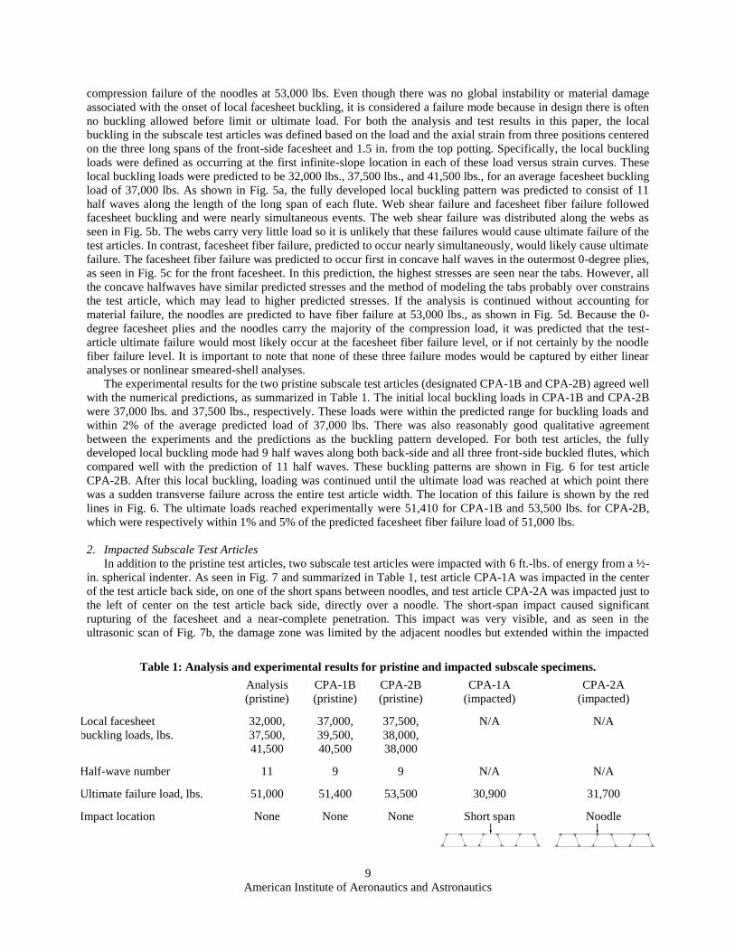
between the experiments and the predictions as the buckling pattern developed. For both test articles, the fully
developed local buckling mode had 9 half waves along both back-side and all three front-side buckled flutes, which
compared well with the prediction of 11 half waves. These buckling patterns are shown in Fig. 6 for test article
CPA-2B. After this local buckling, loading was continued until the ultimate load was reached at which point there
was a sudden transverse failure across the entire test article width. The location of this failure is shown by the red
lines in Fig. 6. The ultimate loads reached experimentally were 51,410 for CPA-1B and 53,500 lbs. for CPA-2B,
which were respectively within 1% and 5% of the predicted facesheet fiber failure load of 51,000 lbs.
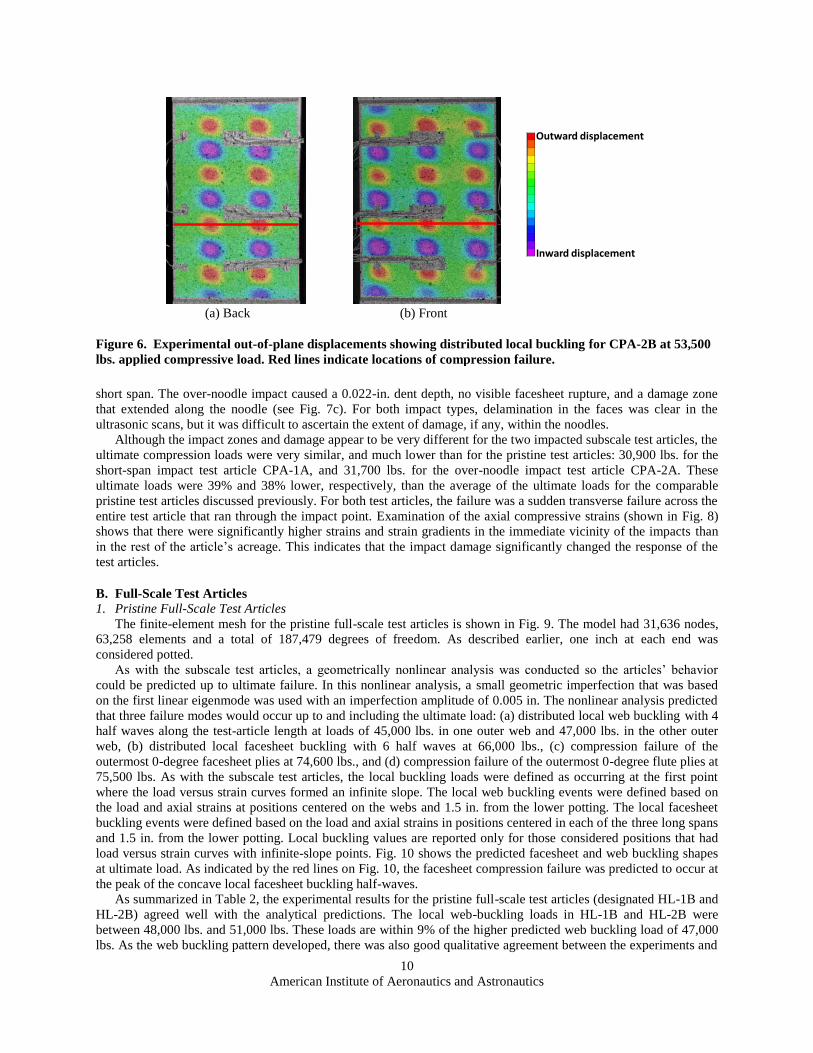
2. Impacted Subscale Test Articles
In addition to the pristine test articles, two subscale test articles were impacted with 6 ft.-lbs. of energy from a ½-
in. spherical indenter. As seen in Fig. 7 and summarized in Table 1, test article CPA-1A was impacted in the center
of the test article back side, on one of the short spans between noodles, and test article CPA-2A was impacted just to
the left of center on the test article back side, directly over a noodle. The short-span impact caused significant
rupturing of the facesheet and a near-complete penetration. This impact was very visible, and as seen in the
ultrasonic scan of Fig. 7b, the damage zone was limited by the adjacent noodles but extended within the impacted
Table 1: Analysis and experimental results for pristine and impacted subscale specimens.
Analysis
(pristine)
CPA-1B
(pristine)
CPA-2B
(pristine)
CPA-1A
(impacted)
CPA-2A
(impacted)
Local facesheet
buckling loads, lbs.
32,000,
37,500,
41,500
37,000,
39,500,
40,500
37,500,
38,000,
38,000
N/A N/A
Half-wave number 11 9 9 N/A N/A
Ultimate failure load, lbs. 51,000 51,400 53,500 30,900 31,700
Impact location None None None Short span
Noodle
10
American Institute of Aeronautics and Astronautics
short span. The over-noodle impact caused a 0.022-in. dent depth, no visible facesheet rupture, and a damage zone
that extended along the noodle (see Fig. 7c). For both impact types, delamination in the faces was clear in the
ultrasonic scans, but it was difficult to ascertain the extent of damage, if any, within the noodles.
Although the impact zones and damage appear to be very different for the two impacted subscale test articles, the
ultimate compression loads were very similar, and much lower than for the pristine test articles: 30,900 lbs. for the
short-span impact test article CPA-1A, and 31,700 lbs. for the over-noodle impact test article CPA-2A. These
ultimate loads were 39% and 38% lower, respectively, than the average of the ultimate loads for the comparable
pristine test articles discussed previously. For both test articles, the failure was a sudden transverse failure across the
entire test article that ran through the impact point. Examination of the axial compressive strains (shown in Fig. 8)
shows that there were significantly higher strains and strain gradients in the immediate vicinity of the impacts than
in the rest of the article’s acreage. This indicates that the impact damage significantly changed the response of the
test articles.
B. Full-Scale Test Articles
1. Pristine Full-Scale Test Articles
The finite-element mesh for the pristine full-scale test articles is shown in Fig. 9. The model had 31,636 nodes,
63,258 elements and a total of 187,479 degrees of freedom. As described earlier, one inch at each end was
considered potted.
As with the subscale test articles, a geometrically nonlinear analysis was conducted so the articles’ behavior
could be predicted up to ultimate failure. In this nonlinear analysis, a small geometric imperfection that was based
on the first linear eigenmode was used with an imperfection amplitude of 0.005 in. The nonlinear analysis predicted
that three failure modes would occur up to and including the ultimate load: (a) distributed local web buckling with 4
half waves along the test-article length at loads of 45,000 lbs. in one outer web and 47,000 lbs. in the other outer
web, (b) distributed local facesheet buckling with 6 half waves at 66,000 lbs., (c) compression failure of the
outermost 0-degree facesheet plies at 74,600 lbs., and (d) compression failure of the outermost 0-degree flute plies at
75,500 lbs. As with the subscale test articles, the local buckling loads were defined as occurring at the first point
where the load versus strain curves formed an infinite slope. The local web buckling events were defined based on
the load and axial strains at positions centered on the webs and 1.5 in. from the lower potting. The local facesheet
buckling events were defined based on the load and axial strains in positions centered in each of the three long spans
and 1.5 in. from the lower potting. Local buckling values are reported only for those considered positions that had
load versus strain curves with infinite-slope points. Fig. 10 shows the predicted facesheet and web buckling shapes
at ultimate load. As indicated by the red lines on Fig. 10, the facesheet compression failure was predicted to occur at
the peak of the concave local facesheet buckling half-waves.
As summarized in Table 2, the experimental results for the pristine full-scale test articles (designated HL-1B and
HL-2B) agreed well with the analytical predictions. The local web-buckling loads in HL-1B and HL-2B were
between 48,000 lbs. and 51,000 lbs. These loads are within 9% of the higher predicted web buckling load of 47,000
lbs. As the web buckling pattern developed, there was also good qualitative agreement between the experiments and
(a) Back (b) Front
Figure 6. Experimental out-of-plane displacements showing distributed local buckling for CPA-2B at 53,500
lbs. applied compressive load. Red lines indicate locations of compression failure.
Positive displacement
Negative displacement
Failure
Outward displacement
Inward displacement
11
American Institute of Aeronautics and Astronautics
the predictions. For both test articles, the fully developed web buckling mode had 6 or 7 half waves along both
external webs. These patterns are shown in Figs. 11a and 11b for test article HL-1B, and compare well to the
prediction of 6 half waves in the webs shown in Figs. 10a and 10b. Interestingly, for both test articles the mode
shape in the webs transitioned between 6 and 7 half waves as the load increased. The second predicted failure mode,
local facesheet buckling, was seen experimentally with measured buckling loads of 66,000 lbs. and 73,000 lbs. for
test article HL-1B; these buckling loads were within 11% of the prediction of 66,000 lbs. For test article HL-2B,
facesheet buckling was measured at 63,000 lbs., 5% lower than the prediction. The experimental buckling modes
were similar to those predicted; however, there was less uniformity in the experimental modes. For example, in the
center flute on the back of HL-1B, initially 7 half waves began to develop, but then the mode transitioned to four
half waves. Looking at the front of HL-1B, the left flute had three half waves skewed toward the bottom and the
buckling in the right flute initially developed 3 half waves, transitioned to 6 half waves, and finally transitioned to 4
half waves by failure. On the back side of HL-2B, 5 half waves developed, and on the front side the two outer flutes
both developed 6 half waves. The experimental out-of-plane displacements, just prior to the ultimate load, for the
faces of HL-1B are shown in Figs. 11c and 11d. Finally, the ultimate failure loads were 75,600 lbs. for HL-1B and
71,300 lbs. for HL-2B, which are about 1% higher and 4% lower than the predicted facesheet failure load of 76,600
lbs., respectively. Because the predicted buckling pattern was nearly symmetric, failure was predicted to occur
essentially simultaneously in outward facing local buckles on both the front and back. On HL-1B, the failure
occurred through an outer half wave on the back and through inner and outer half waves on the front; failure
(a) Impacted subscale test articles CPA-1A (left) and CPA-2A (right)
(b) Ultrasonic scan of CPA-1A impacted region (c) Ultrasonic scan of CPA-2A impacted region
Figure 7. Impacted subscale test articles.
Noodles
Impact sites
1.54 in.1.20 in.

12
American Institute of Aeronautics and Astronautics
locations are shown with the red lines in Fig. 11. However, on HL-2B the failure occurred through one of the
outward half waves on the front and through an inward half wave on the back; it was difficult to determine whether
the failure began on the front or the back.
2. Impacted Full-Scale Test Articles
Two full-scale test articles were also tested after impact with 6 ft.-lbs. of energy from a ½-in. spherical indenter.
Test article HL-1A was impacted in the center of the test article back side, over the long span between noodles, and
test article HL-2A was impacted on the test article front side directly over a noodle (Table 2). The large-span impact
caused visible damage with a dent depth of 0.005 in., and no visible facesheet rupture. This impact is seen in the
ultrasonic scan of Fig. 12a; the damage consisted of delaminations at multiple interfaces through the facesheet
laminate. The over-noodle impact caused a 0.003-in. dent depth, and no visible facesheet rupture. In this case the
damage zone was contained within the noodle region, and consisted of multiple delaminations through the thickness
of the facesheet (Fig. 12b). For impact at both locations, delamination in the facesheets were clear in the ultrasonic
scans. However, it was difficult to ascertain the extent of damage, if any, within the noodle in the case of the over-
noodle impact.
As summarized in Table 2, both of the impacted full-scale test articles progressed through the failure modes in a
manner similar to the pristine test articles. Both local web buckling and local facesheet buckling were observed in
the impacted test articles. Local web buckling occurred between 49,000 lbs. and 53,000 lbs., within 13% of the
larger pristine prediction of 47,000 lbs. for the pristine panels. Each of the outer webs of HL-1A and HL-2A had 6
or 7 half waves, with transitions from 7 to 6 half waves in three of the four outer webs of the impacted test articles.
The fourth outer web had 7 half waves and did not change mode. Test article HL-1A had a local facesheet buckling
load of 66,000 lbs., which was the same as the pristine predicted load. Test article HL-1A developed 5 half waves in
the center flute on the back side and 4 half waves in each of the outer flutes of the front side. Test article HL-2A
developed 7 half waves in the center flute on the back side and 4 half waves in each of the outer flutes on the front
side, but the buckling loads could not be quantified because the considered load vs. strain curves did not have any
points of infinite slope. The ultimate failure loads for HL-1A and HL-2A were 68,000 lbs. and 61,600 lbs.,
respectively. These failure loads were respectively 9% and 17% lower than the failure loads predicted for the
pristine panels and 7% and 16% lower than the average failure load of the pristine experimental test articles. Though
these failure loads are lower than those of the pristine test articles, there was no discernable change in the deformed
shapes or strain contours due to the impact damage. This is in contrast to the subscale test articles, which showed
localized high strains in the vicinity of the impact sites.
VI. Concluding Remarks
Fluted-core composite structures have the potential to provide benefits over traditional sandwich composites for
certain aerospace applications, and recent advances in manufacturing methods have made the use of the fluted-core
(a) CPA-1A at 30,900 lbs. (b) CPA-2A at 31,600 lbs.
applied compressive load. applied compressive load.
Figure 8. Experimentally observed axial strains for impacted subscale specimens.
Least negative strain
Most negative strain
Failure

13
American Institute of Aeronautics and Astronautics
construction more practical. However, if these structures are to be more widely used, the behavior of fluted-core
composites needs to be well understood. Because the primary loading condition in many applications would be
compression, the compression behavior of two fluted-core constructions was considered both experimentally and
analytically. Both pristine and impact-damaged test articles were tested. Analyses of the pristine test articles were
performed and good qualitative and quantitative agreement was obtained between experimentation and analysis.
Both buckling and strength failures were observed in the tested components. The stability failures resulted in plate-
like local buckling patterns that were axially distributed along individual flutes. Depending on the sectional design,
these patterns developed in either the facesheets or in the webs. Though these local-buckling events were not
catastrophic by themselves, the deformations associated with the local buckling patterns led to material strength
failures as loading was increased into the post-buckled range of loading. Considering this, it is important to note that
the proper material failures would not be captured by either linear analyses or nonlinear smeared-shell analyses.
Nondestructive inspection of the damage zones in impacted test articles showed that the detectable damage region
was limited to no more than one flute on either side of the impact. More study is needed, but this may indicate an
inherent damage-arresting capability associated with fluted core. This capability could prove beneficial when
designing weight-critical damage-tolerant structures for a variety of loading conditions and final products.
VII. References 1McArthur, J. Craig, “Ares I Crew Launch Vehicle, Upper Stage Element Overview,” July 23, 2008, online presentation,
URL: http://ntrs.nasa.gov/archive/nasa/casi.ntrs.nasa.gov/20090002561_2008048226.pdf, [cited 23 December, 2010]. 2Cockrell, Charles E., Jr., “Ares V: Overview and Status,” October 12-16, 2009, online presentation, URL:
http://ntrs.nasa.gov/archive/nasa/casi.ntrs.nasa.gov/20090043023_2009044061.pdf, [cited 23 December, 2010]. 3Jegley, Dawn C., “A Study of the Structural Efficiency of Fluted Core Graphite-Epoxy Panels,” NASA TM-101681, 1990. 4Libove, C., and Hubka, Ralph E., “Elastic Constants for Corrugated-Core Sandwich Plates,” NACA TN 2289, 1951. 5Seide, Paul, “The Stability Under Longitudinal Compression of Flat Symmetric Corrugated-Core Sandwich Plates with
Simply Supported Loaded Edges and Simply Supported or Clamped Unloaded Edges,” NACA TN 2679, 1952. 6Lok, Tat-Seng, and Cheng, Qian-Hua, “Elastic Stiffness Properties and Behavior of Truss-Core Sandwich Panel,” Journal of
Structural Engineering, May 2000, pp. 552-559. 7Chang, Wan-Shu, Ventsel, Edward, Krauthammer, Ted, and John, Joby, “Bending Behavior of Corrugated-Core Sandwich
Plates,” Composite Structures, Vol. 70, 2005, pp. 81-89. 8Martinez, Oscar A., Sankar, Bhavani V., Haftka, Raphael T., Bapanapalli, Satish K., and Blosser, Max L.,
“Micromechanical Analysis of Composite Corrugated-Core Sandwich Panels for Integral Thermal Protection Systems,” AIAA
Journal, Vol. 45, No. 9, September 2007, pp. 2323-2336.
Figure 9. Finite-element mesh for the full-scale test articles.

14
American Institute of Aeronautics and Astronautics
9Sharma, Anurag, Sankar, Bhavani V., and Haftka, Raphael T., “Homogenization of Plates with Microsctructure and
Application to Corrugated Core Sandwich Panels,” 51st AIAA/ASME/ASCE/AHS/ASC Structures, Structural Dynamics, and
Materials Conference, Orlando, FL, 12-15 April 2010, AIAA Paper No. AIAA 2010-2706. 10Robinson, Michael J., Stoltzfus, Joel M., and Owens, Thomas N., “Composite Material Compatibility with Liquid and
Gaseous Oxygen,” 42nd AIAA/ASME/ASCE/ASC Structures, Structural Dynamics, and Materials Conference and Exhibit, Seattle,
WA, 16-19 April 2001, AIAA Paper No. AIAA 2001-1215. 11Robinson, Michael J., Johnson, Scott E., Eichinger, Jeffrey D., Hand, Michael L., and Sorensen, Eric T., “Trade Study
Results for a Second-Generation Reusable Launch Vehicle Composite Hydrogen Tank,” 45th AIAA/ASME/ASCE/AHS/ASC
Structures, Structural Dynamics & Materials Conference, 19-22 April 2004, Palm Springs, CA, AIAA Paper No. AIAA 2004-
1932. 12Ardelean, Emil, Gerhart, Charlotte, Henderson, Kyle, Griffin, Steve, Lazzaro, Anthony, Evert, Michael, and McCrary,
Warren, “Experiment Overview and Flight Results Summary From The Vibro Acoustic Launch Protection Experiment
(VALPE),” AIAA Space 2004 Conference and Exhibit, San Diego, CA, 28-30 September 2004, AIAA Paper No. AIAA 2004-
5890. 13Kothari, Ajay P., Livingston, John W., Tarpley, Christopher, Raghavan, Venkatraman, Bowcutt, Kevin G., and Smith,
Thomas R., “A Reusable, Rocket and Airbreathing Combined Cycle Hypersonic Vehicle Design for Access-to-Space,” AIAA
Space 2010 Conference and Exposition, 30 August-2 September 2010, AIAA Paper No. AIAA 2010-8905.
(a) Left web (b) Right web
(c) Back facesheet (d) Front facesheet
Figure 10. Predicted out-of-plane displacements for the
predicted ultimate load (74,600 lbs.).
Potted Area
Potted Area

15
American Institute of Aeronautics and Astronautics
14Campbell, F. C., Manufacturing Processes for Advanced Composites, Elsevier, New York, 2004. 15Guzman, Juan C., and McCarville, Douglas A., “Comprehensive Overview of Fluted Core for Weight Critical
Applications,” Airtec Supply on the Wings, Frankfurt, Germany, 2010 (abstract and presentation only). 16VIC-3D, Software Package, Ver. 2010.1.0, Correlated Solutions, Inc., Columbia, SC, 2010. 17MSC.PATRAN 2010, Software Package, MSC.Software Corporation, Santa Ana, CA, 2010. 18Abaqus/Standard, Software Package, Ver. 6.9.1, SIMULIA, Providence, RI, 2009. 19Abaqus/CAE, Software Package, Ver. 6.9.1, SIMULIA, Providence, RI, 2009. 20Reeder, James R., “Property Values for Preliminary Design of the Ares I Composite Interstage,” Memo, 14 March 2007,
pg. 7, Table 1, 1st column.
Table 2: Analysis and experimental results for pristine and impacted full-scale specimens.
Analysis
(pristine)
HL-1B
(pristine)
HL-2B
(pristine)
HL-1A
(impacted)
HL-2A
(impacted)
Local web buckling loads, lbs. 45,000,
47,000
50,500,
51,000
48,000,
49,000
50,000,
53,000
49,000,
49,000
Local facesheet
buckling loads, lbs.
66,000 73,000,
66,000
63,000 66,000 N/A
Final half-wave number
(right, left, back, front)
6, 6, 4, 4 7, 6, 4, 3&4 N/A, 6, 5, 6 7, 6, 5, 4 6, 6, 7, 4
Ultimate failure load, lbs. 74,600 75,600 71,300 68,000 61,600
Impact location None None None Long span
Noodle

16
American Institute of Aeronautics and Astronautics
(a) Left web (b) Right web
(c) Back facesheet (d) Front facesheet
Figure 11. Experimental out-of-plane displacements for HL-1B just prior to failure (75,600
lbs.). Red lines indicate locations of compression failure.
Outward displacement
Inward displacement
(a) Ultrasonic scan of HL-1A impacted region. (b) Ultrasonic scan of HL-2A impacted region.
Figure 12. Impacted full-scale test articles.
Noodle
Impact sites
1.0 in.
0.55 in.