Brück Michael von - Aspects of Sunyata and Consciousness in Mahayana-Buddhism
Nanocomposites
INM – Leibniz Institute of New Materials
Stefan Brück
1.7.2014 Webinar
Nanoparticles, The Key Element
Nanoparticles + Matrix + ??? = Nanocomposite
2D Nanocomposites: Coatings
Examples of Applications
7/1/2014 presentation du projet 2 7/1/2014 2
Agenda
3
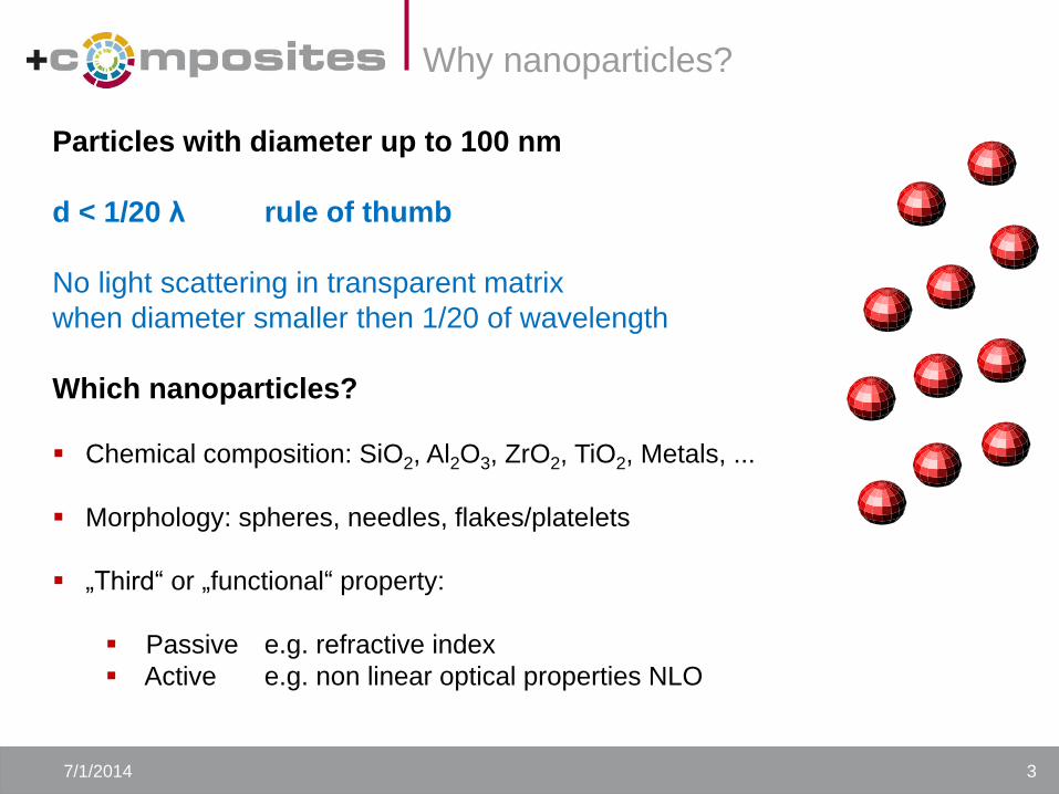
Particles with diameter up to 100 nm
d < 1/20 λ rule of thumb
No light scattering in transparent matrix
when diameter smaller then 1/20 of wavelength
Which nanoparticles?
Chemical composition: SiO2, Al2O3, ZrO2, TiO2, Metals, ...
Morphology: spheres, needles, flakes/platelets
„Third“ or „functional“ property:
Passive e.g. refractive index
Active e.g. non linear optical properties NLO
7/1/2014 3
Why nanoparticles?

7/1/2014 4
Properties by nanoparticles
Optical properties
No light scattering by NP, color can be selected
Adaptable refractive index e.g. for light guide adhesives
UV / IR protection with absorbing nanoparticles
Electrical properties
Electical conductive but transparent coatings
Printable electronics
Magnetic properties (superparamagnetic iron oxide < 30 nm)
Temperature increase in magnetic field for bond/disbond-on-command
Rheological properties
Adapting viscosity of reactive mixtures
Thermo-/mechanical properties
Reduction of thermal expansion
Scratch and/or abrasion resistance
Anti-Friction, corrosion protection…
5
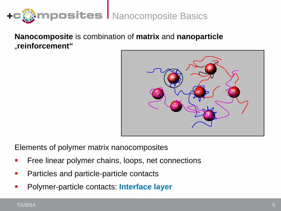
Elements of polymer matrix nanocomposites
Free linear polymer chains, loops, net connections
Particles and particle-particle contacts
Polymer-particle contacts: Interface layer
Nanocomposite is combination of matrix and nanoparticle
„reinforcement“
7/1/2014 5
Nanocomposite Basics
7/1/2014 6
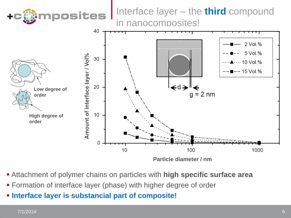
Interface layer – the third compound
in nanocomposites!
Attachment of polymer chains on particles with high specific surface area
Formation of interface layer (phase) with higher degree of order
Interface layer is substancial part of composite!
Low degree of
order
High degree of
order
Particle diameter / nm
7
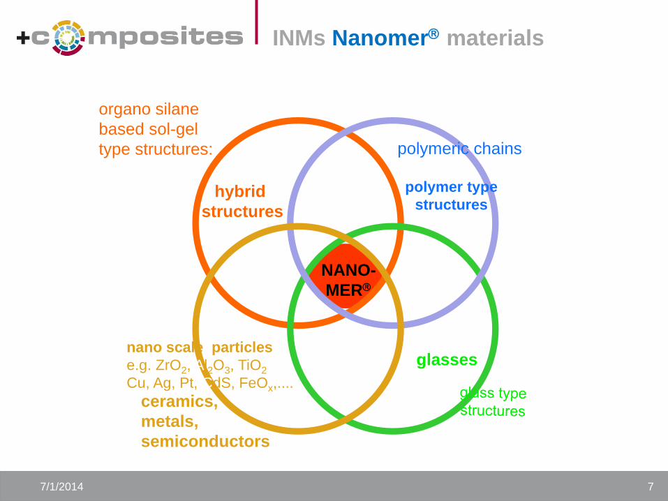
NANO-
MER
organo silane
based sol-gel
type structures:
hybrid
structures
glasses
polymer type
structures
polymeric chains
nano scale particles
e.g. ZrO2, Al2O3, TiO2
Cu, Ag, Pt, CdS, FeOx,....
ceramics,
metals,
semiconductors
7/1/2014 7
INMs Nanomer materials
8
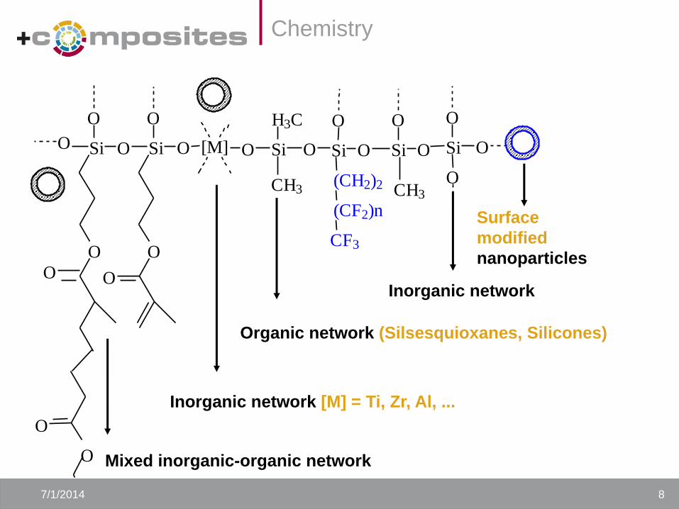
Inorganic network
O S i
O
O
Inorganic network [M] = Ti, Zr, Al, ...
O [ M ]
Mixed inorganic-organic network
O
O
O
O S i S i O
O
O O
O
O
Surface
modified
nanoparticles
Organic network (Silsesquioxanes, Silicones)
C F 3
( C F 2 ) n
( C H 2 ) 2
O S i O S i O
O O
C H 3
S i O
H 3 C
C H 3
7/1/2014 8
Chemistry
9
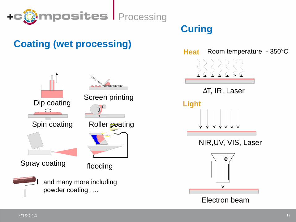
Curing
Heat
Light
D T, IR, Laser
Room temperature - 350°C
NIR,UV, VIS, Laser
Electron beam
e -
Coating (wet processing)
Dip coating
Spin coating
Spray coating
Roller coating
Screen printing
flooding
and many more including
powder coating ….
7/1/2014 9
Processing
Wet chemical deposited TCO
coatings
10 7/1/2014 10
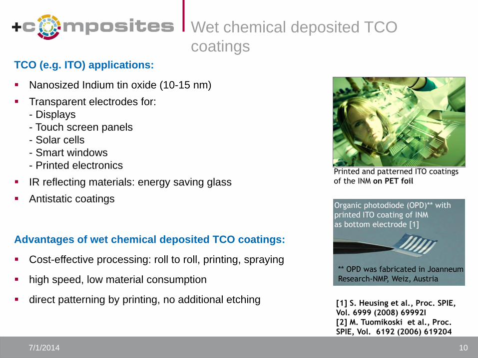
TCO (e.g. ITO) applications:
Nanosized Indium tin oxide (10-15 nm)
Transparent electrodes for:
- Displays
- Touch screen panels
- Solar cells
- Smart windows
- Printed electronics
IR reflecting materials: energy saving glass
Antistatic coatings
Advantages of wet chemical deposited TCO coatings:
Cost-effective processing: roll to roll, printing, spraying
high speed, low material consumption
direct patterning by printing, no additional etching [1] S. Heusing et al., Proc. SPIE,
Vol. 6999 (2008) 69992I
[2] M. Tuomikoski et al., Proc.
SPIE, Vol. 6192 (2006) 619204
Printed and patterned ITO coatings
of the INM on PET foil
Organic photodiode (OPD)** with
printed ITO coating of INM
as bottom electrode [1]
** OPD was fabricated in Joanneum
Research-NMP, Weiz, Austria
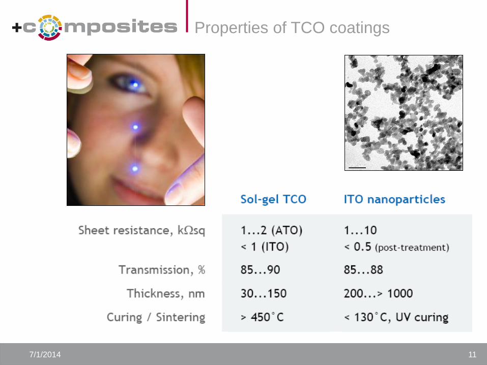
Properties of TCO coatings
7/1/2014 11
CB
conduction band
forbidden zone /
Band gap 3.2 eV
valence band
VB
UV-Light
<388 nm
O2
.O2-+H+ HO2
.
H2O
.OH + H+
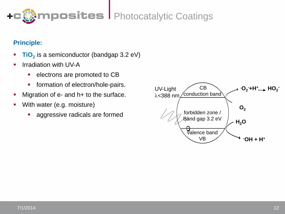
Photocatalytic Coatings
7/1/2014 12
Principle:
TiO2 is a semiconductor (bandgap 3.2 eV)
Irradiation with UV-A
electrons are promoted to CB
formation of electron/hole-pairs.
Migration of e- and h+ to the surface.
With water (e.g. moisture)
aggressive radicals are formed
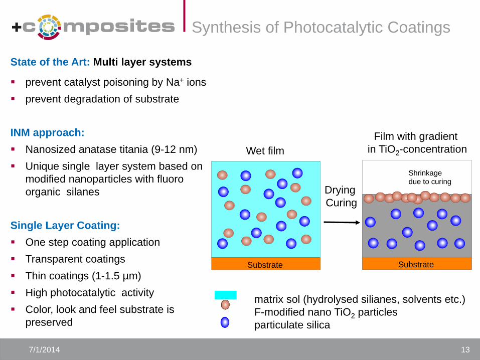
Wet film
Film with gradient
in TiO2-concentration
Drying
Curing
matrix sol (hydrolysed silianes, solvents etc.)
F-modified nano TiO2 particles
particulate silica
Substrate
Shrinkagedue to curing
Substrate
Synthesis of Photocatalytic Coatings
7/1/2014 13
State of the Art: Multi layer systems
prevent catalyst poisoning by Na+ ions
prevent degradation of substrate
INM approach:
Nanosized anatase titania (9-12 nm)
Unique single layer system based on
modified nanoparticles with fluoro
organic silanes
Single Layer Coating:
One step coating application
Transparent coatings
Thin coatings (1-1.5 µm)
High photocatalytic activity
Color, look and feel substrate is
preserved
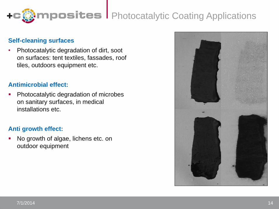
Photocatalytic Coating Applications
7/1/2014 14
Self-cleaning surfaces
• Photocatalytic degradation of dirt, soot
on surfaces: tent textiles, fassades, roof
tiles, outdoors equipment etc.
Antimicrobial effect:
Photocatalytic degradation of microbes
on sanitary surfaces, in medical
installations etc.
Anti growth effect:
No growth of algae, lichens etc. on
outdoor equipment
Pigmented, fine-textured tribological composite materials
16 www.inm-gmbh.de
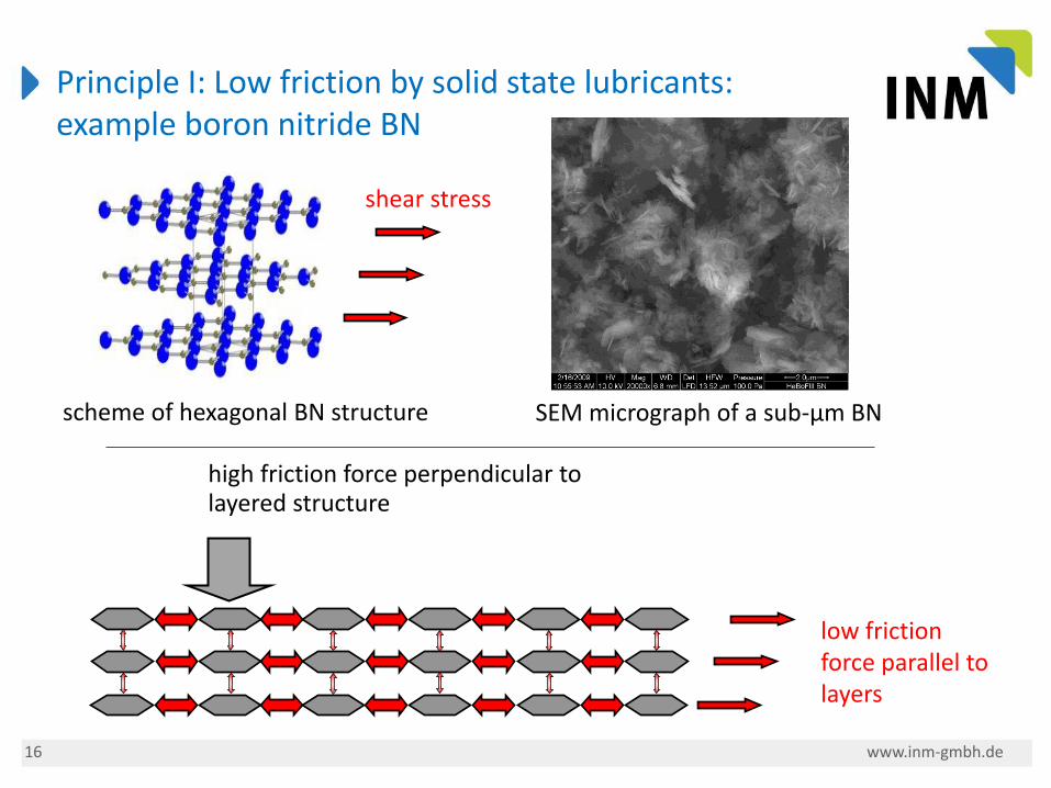
high friction force perpendicular to layered structure
low friction force parallel to layers
Principle I: Low friction by solid state lubricants: example boron nitride BN
scheme of hexagonal BN structure SEM micrograph of a sub-µm BN
shear stress
17 www.inm-gmbh.de
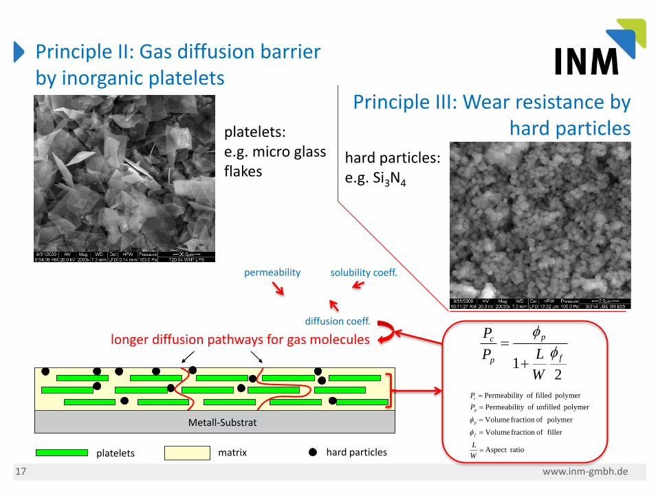
Principle II: Gas diffusion barrier by inorganic platelets/ Hartstoffe in Polymermatrix
Platelets Nano-Particles Matrix
Substrate
Pathways
Metall-Substrat
longer diffusion pathways for gas molecules
platelets: e.g. micro glass flakes
hard particles: e.g. Si3N4
hard particles platelets
Principle III: Wear resistance by hard particles
21
f
p
p
c
W
LP
P
ratioAspect
filler offraction Volume
polymer offraction Volume
polymer unfilled ofty Permeabili
polymer filled ofty Permeabili
W
L
P
P
f
p
p
c
matrix
permeability
diffusion coeff.
solubility coeff.
18 www.inm-gmbh.de
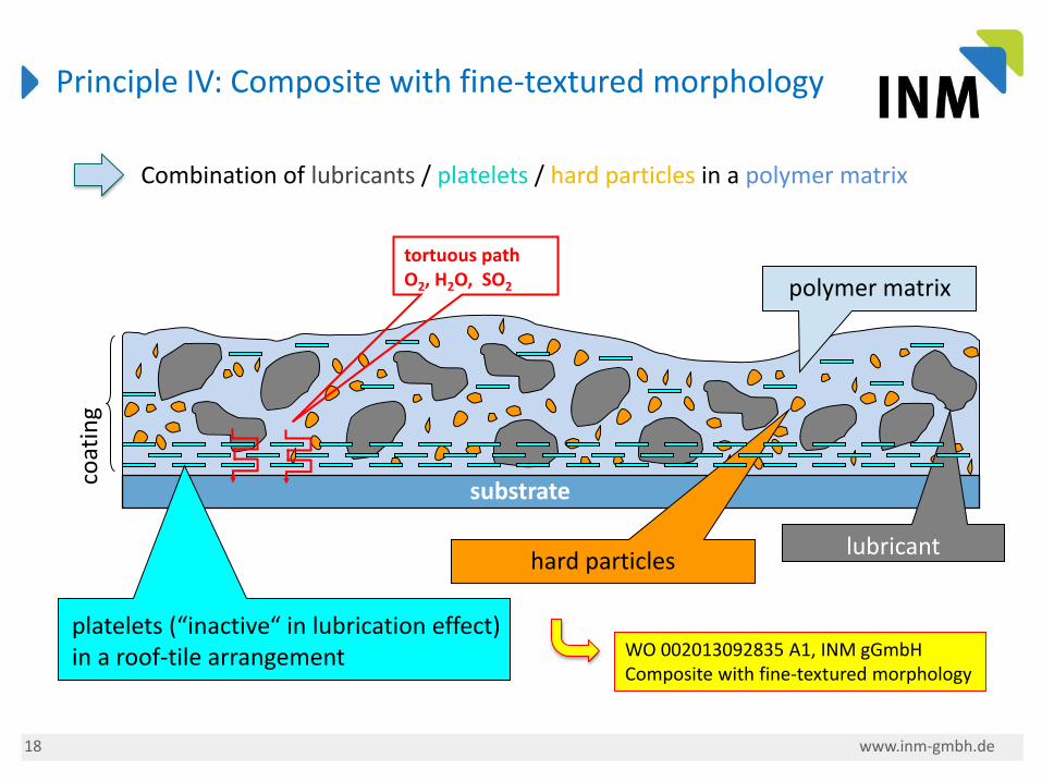
Principle IV: Composite with fine-textured morphology
hard particles
polymer matrix
coat
ing
lubricant
substrate
tortuous path O2, H2O, SO2
platelets (“inactive“ in lubrication effect) in a roof-tile arrangement WO 002013092835 A1, INM gGmbH
Composite with fine-textured morphology
Combination of lubricants / platelets / hard particles in a polymer matrix
19 www.inm-gmbh.de
coat
ing
metal substrate
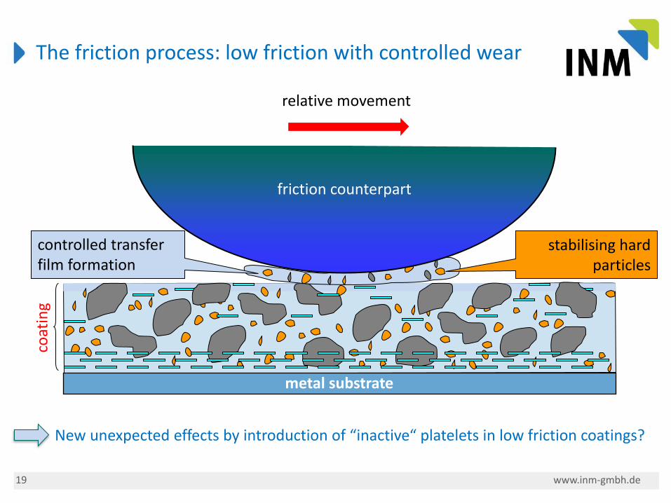
controlled transfer film formation
relative movement
stabilising hard particles
The friction process: low friction with controlled wear
friction counterpart
New unexpected effects by introduction of “inactive“ platelets in low friction coatings?
21 www.inm-gmbh.de
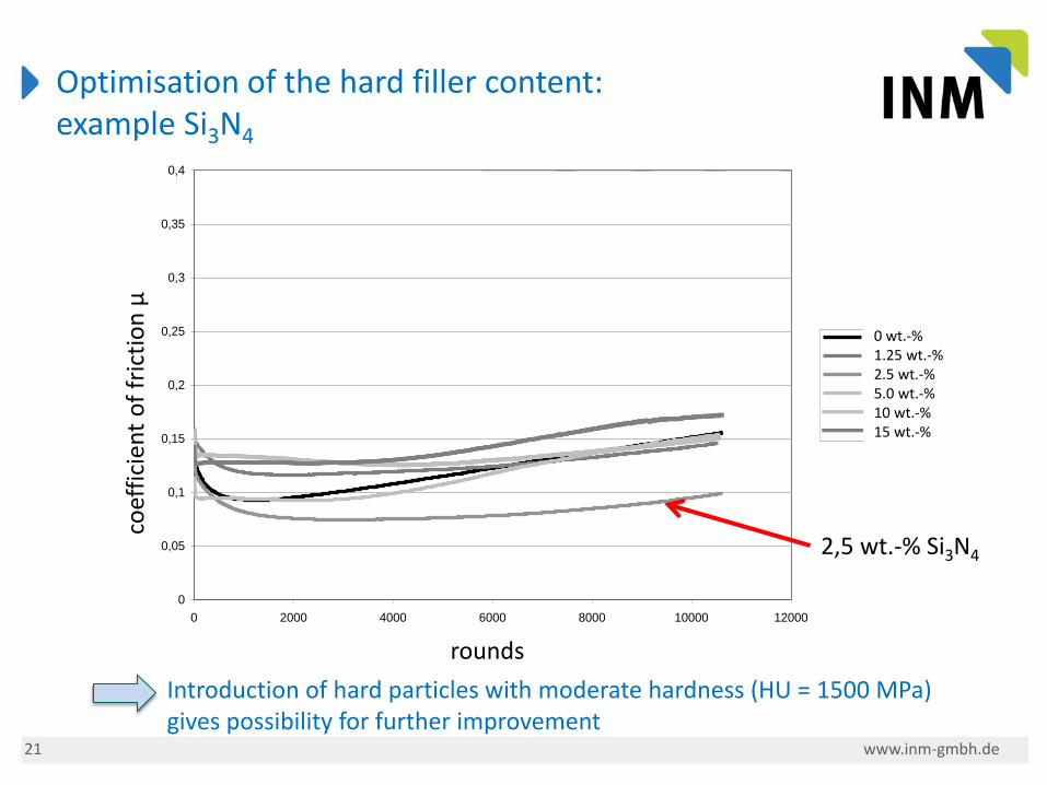
Optimisation of the hard filler content: example Si3N4
Reihe Si3N4 E05 mit 30% BN 110 / 5% LS / 10% FL
0
0,05
0,1
0,15
0,2
0,25
0,3
0,35
0,4
0 2000 4000 6000 8000 10000 12000
Runden
Reib
un
gsko
eff
izie
nt
µ
A 200 / 0% Si3N4 E05
A 233 / 1,25% Si3N4 E05
A 234 / 2,5% Si3N4 E05
A 235 / 5,0% Si3N4 E05
A 236 / 10% Si3N4 E05
A 237 / 15% Si3N4 E05
2,5 wt.-% Si3N4
coef
fici
ent
of
fric
tio
n µ
rounds
0 wt.-% 1.25 wt.-% 2.5 wt.-% 5.0 wt.-% 10 wt.-% 15 wt.-%
Introduction of hard particles with moderate hardness (HU = 1500 MPa) gives possibility for further improvement
22 www.inm-gmbh.de
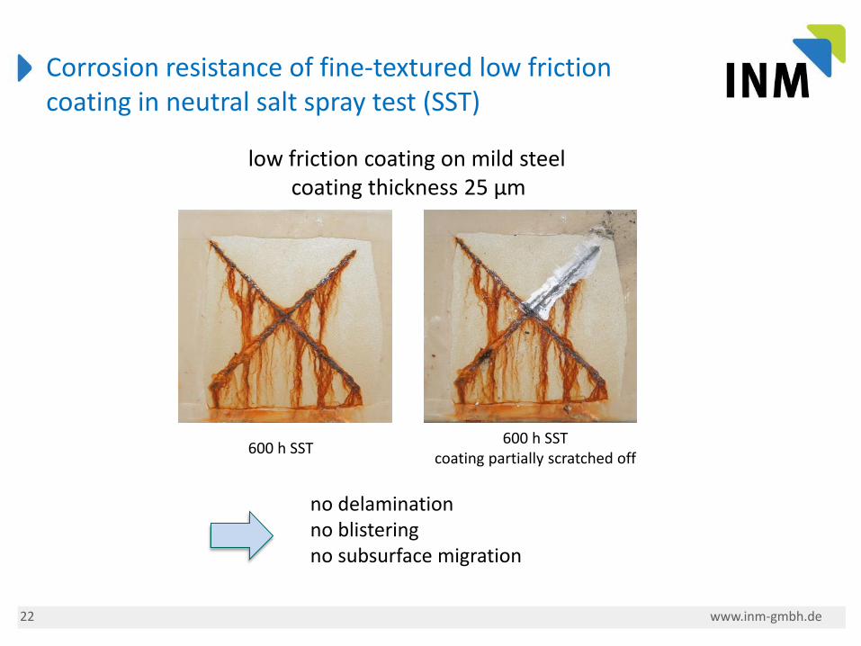
600 h SST 600 h SST
coating partially scratched off
Corrosion resistance of fine-textured low friction coating in neutral salt spray test (SST)
low friction coating on mild steel coating thickness 25 µm
no delamination no blistering no subsurface migration
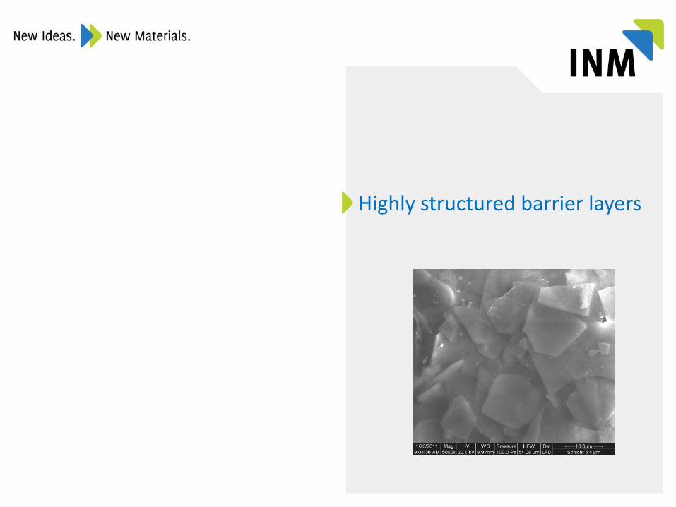
Highly structured barrier layers
24 www.inm-gmbh.de
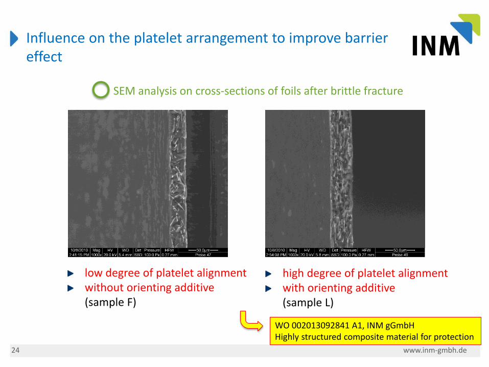
Influence on the platelet arrangement to improve barrier effect
high degree of platelet alignment with orienting additive
(sample L)
low degree of platelet alignment without orienting additive
(sample F)
SEM analysis on cross-sections of foils after brittle fracture
WO 002013092841 A1, INM gGmbH Highly structured composite material for protection
25 www.inm-gmbh.de
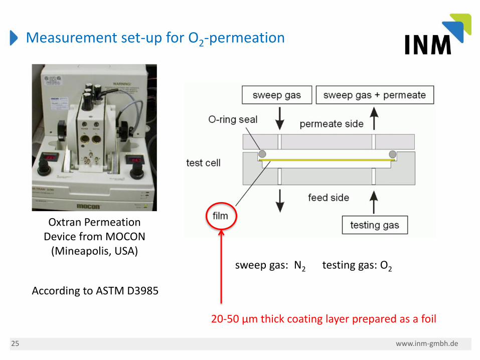
Measurement set-up for O2-permeation
Oxtran Permeation Device from MOCON
(Mineapolis, USA) sweep gas: N2 testing gas: O2
According to ASTM D3985
20-50 µm thick coating layer prepared as a foil
26 www.inm-gmbh.de
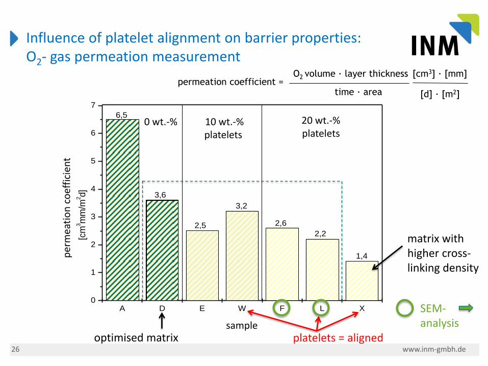
A D E W F L X0
1
2
3
4
5
6
7
1,4
3,2
2,2
2,62,5
3,6
6,5
Perm
eatio
nsk
oeff
izie
nt
[cm
3m
m/m
2d]
Beschichtungsnummer
0 wt.-% 10 wt.-% platelets
20 wt.-% platelets
Influence of platelet alignment on barrier properties: O2- gas permeation measurement
permeation coefficient = O2 volume · layer thickness
time · area
[cm3] · [mm]
[d] · [m2]
per
mea
tio
n c
oef
fici
ent
sample platelets = aligned optimised matrix
SEM- analysis
matrix with higher cross-linking density
INM - Leibniz Institut für Neue Materialien gGmbH
Campus D2 2
66123 Saarbrücken
www.inm-gmbh.de
Dr. Cenk Aktas
Stefan Brück
+Composites Webseite
www.pluscomposites.eu
29 7/1/2014
Contacts Germany