COMPLETE PROGRAM 41 - bre-trafo.de · 10 07/2016 Definition of Transformers Toroidal variable...
136
COMPLETE PROGRAM 41
Transcript of COMPLETE PROGRAM 41 - bre-trafo.de · 10 07/2016 Definition of Transformers Toroidal variable...

COMPLETE PROGRAM 41

07/20162 www.bre-trafo.com

307/2016 www.bre-trafo.com
Content
Transformer world Breimer-Roth GmbH ................................................................................................................. 5 Where to find us .................................................................................................................................................... 6 Our services for you .............................................................................................................................................. 7 Standards/guidelines/regulations ......................................................................................................................... 8 Definition of transformers ..................................................................................................................................... 9 General technical information ............................................................................................................................. 11 Definition of terms .............................................................................................................................................. 13
1 | SINGLE-PHASE TRANSFORMERSBSV Control transformers, low losses ........................................................................................................................ 18 BS Control transformers, cost optimized ................................................................................................................. 20 BEV Single-phase transformers, low losses, customer specific version ..................................................................... 22 BE Single-phase transformers, cost-optimized, customer specific version ............................................................. 23 BSUS Control transformers, UI, standing ...................................................................................................................... 24 BSUL Control transformers, UI, lying ............................................................................................................................ 25 BEUT Single-phase universal transformers ................................................................................................................... 26 BUF Single-phase transformers, UI, cost-optimized, customer specific version ........................................................ 27 BUVA Single-phase transformers, UI, low losses, customer specific version ................................................................ 28 BUH Single-phase transformers, UI, cost-optimized, customer specific version ........................................................ 29 BELT Single-phase auto transformers (for fan and motor regulation) ......................................................................... 30 BBIT Building sites insulating isolation transformer .................................................................................................... 31 BMED Single-phase isolating transformer for supply of medical rooms ....................................................................... 32 BOPL Single-phase isolating transformer for supply of surgical lights ......................................................................... 33
2 | THREE-PHASE TRANSFORMERSBDLT Three-phase auto transformers (for fan and motor regulation) .......................................................................... 40 BDUT Three-phase universal transformers ................................................................................................................... 41 BDF Three-phase transformers, cost-optimized, customer specific version .............................................................. 42 BDVA Three-phase transformers, low power losses, customer specific version .......................................................... 44 BDH Three-phase transformers, cost-optimized, customer specific version .............................................................. 46 BNLB Three-phase transformers to create a neutral formers ...................................................................................... 48 BDSW Universal three-phase transformers ................................................................................................................... 49 BDMED Three-phase isolating transformer for supply of medical rooms ........................................................................ 52
3 | CHOKES AND FILTERBEND 4 Single-phase line chokes 4% ............................................................................................................................... 56 BEND 6 Single-phase line chokes 6% ............................................................................................................................... 58 BENDD 4 Single-phase line dual choke 4% ......................................................................................................................... 60 BENDD 6 Single-phase line dual choke 6% ......................................................................................................................... 62 BEFD 5,5 Single-phase filter choke 5,5% (214 Hz) .............................................................................................................. 64 BDFD 7 Three-phase filter chokes 7% (189Hz) ................................................................................................................. 65 BDFD 14 Three-phase filter chokes 14% (134Hz) ............................................................................................................... 66 BDND 4 Three-phase line chokes 4% ............................................................................................................................... 67 BDND 6 Three-phase line chokes 6% ............................................................................................................................... 68
4 | VARIABLE TOROIDAL TRANSFORMERS BERS 684 Single-phase variable toroidal auto transformers, model 684 ............................................................................ 74 BERS 757 Single-phase variable toroidal auto transformers, model 757 ............................................................................ 76 BERS 832 Single-phase variable toroidal auto transformers, model 832 ............................................................................ 78 BDRS 687 Three-phase variable toroidal auto transformers, model 687 ............................................................................. 80 BDRS 832 Three-phase variable toroidal auto transformers model 832 ............................................................................. 82 Accessories for variable toroidal auto transformers ........................................................................................... 84 BESKH Single-phase voltage stabilizer ............................................................................................................................ 86 BDSKH Three-phase voltage stabilizer ............................................................................................................................ 87
Page

07/20164 www.bre-trafo.com
5 | POWER SUPPLIESBENT Single-phase power supplies .............................................................................................................................. 91 BDNTS Three-phase power supplies, standing ............................................................................................................... 92 BDNTL Three-phase power supplies, laid ....................................................................................................................... 93 D-IPS-C Controllable power supply for TS35 top hat rail , primary-switched ................................................................... 94 D-IPS-BM DC UPS ................................................................................................................................................................ 95 MDR/SDR Single-phase power supply, primary switched (low cost) ................................................................................... 96 WDR Dual-phase power supply, primary switched (low cost) ...................................................................................... 98 DRH/DRT Three-phase power supply, primary switched (low cost) .................................................................................... 99 DR-RDN Redundancy module ......................................................................................................................................... 100 DR-UPS DC UPS, (low cost) ............................................................................................................................................. 100
6 | ENCLOSURES AND ACCESSORIESBG Standing enclosures .......................................................................................................................................... 104 BG Wall mounted enclosures .................................................................................................................................. 105 BG Enclosure of glass fibre reinforced plastic ........................................................................................................ 106 BBG Assembly enclosure .......................................................................................................................................... 107 BBG Cube enclosure ................................................................................................................................................. 108 BSS Control cabinet (Rittal) ...................................................................................................................................... 109 Accessories, cable glands ................................................................................................................................. 110 Accessories, filter fan ........................................................................................................................................ 110 Accessories, floor socket .................................................................................................................................. 111 Accessories, Cabinet roles ................................................................................................................................ 111
7 | ELECTRICAL ACCESSORIES Main switch ....................................................................................................................................................... 114 Transformer protection switch .......................................................................................................................... 114 Motor protection switch ................................................................................................................................... 115 Circuit breaker .................................................................................................................................................. 115 Miniature circuit breakers ................................................................................................................................. 116 Fuses ................................................................................................................................................................. 117 Connection cable .............................................................................................................................................. 117 Panel meters ..................................................................................................................................................... 118 Socket/plug ....................................................................................................................................................... 118 BDESB Inrush current limiter ........................................................................................................................................ 120
8 | OTHER AC UPS / frequency converter .......................................................................................................................... 122 Bonding Enamels, trapeze and air coils ............................................................................................................ 124 Components and building group assembly ....................................................................................................... 124 Casting of components / assemblies ................................................................................................................ 125 Switchboards .................................................................................................................................................... 125 Toroidal transformers ........................................................................................................................................ 126 Print transformers (pcb transformers) and coils ............................................................................................... 126
General delivery conditions ............................................................................................................................... 127
Content Page

507/2016 www.bre-trafo.com
Welcome
to the world of transformers at Breimer-Roth Transformatorenwerke GmbH.
We are looking for a long term relationship with our customers, based on a reliable and fair cooperation so it becomes
evident that we are the right partner to achieve your objectives.
To achieve this goal we strive for an open communication through all phases of our cooperation to combine your wants
and needs with our product and service offerings.
Through sustainable added values we want to create economic conditions for our effectiveness in the future. This
includes the continued development of energy efficient products.
Our strengths are solutions of customized task and custom made devices, which go far beyond our catalog.
In the following catalog pages we present our standard program.
For further information don’t hesitate to contact us. We will assist your personally.
Wolfgang Orio
Dipl.-Betriebswirt
-CEO-
Master of business administration
Transformer world Breimer-Roth GmbH
07/20166 www.bre-trafo.com
DARMSTADT
WEINHEIM
FÜRTH
HEIDELBERG
HEPPENHEIM(Bergstraße)
BENSHEIM MICHELSTADT
HÖCHST(Odenwald)
GROSS-UMSTADT GROSSWALLSTADT
WERTHEIM
NIEDERNBERG
AMORBACH
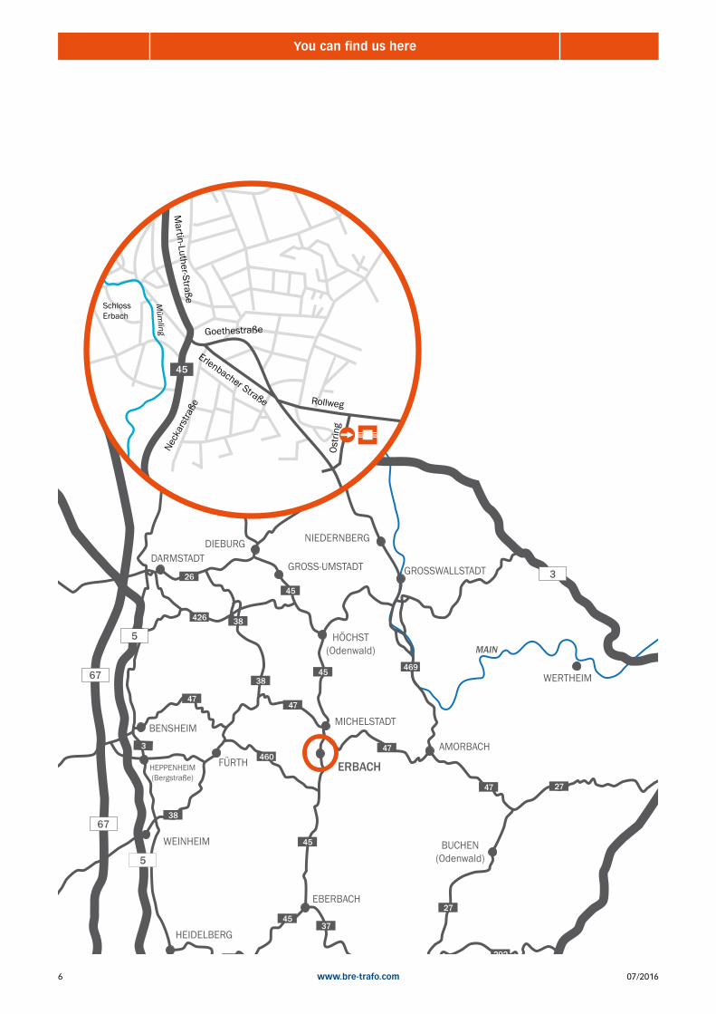
ERBACH
EBERBACH
BUCHEN(Odenwald)
DIEBURG
MAIN
67
67
3
5
5
45
26
469
47
47
47 27
27
292
37
45
460
38
38
47
38426
45
45
45
3
Martin-Luther-Straße
Goethestraße
Neck
arst
raße
Rollweg
Ostri
ng
Erlenbacher Straße
Müm
ling
45
SchlossErbach
You can find us here
707/2016 www.bre-trafo.com
Our services for you
• advises for power supply and voltage adjustment
• development and production of inductance
• development of energy efficient power supplies
• effective and innovative solutions from singe pieces up to series
• participation in the early stages of concept development
• analysis of the relevant parameters and creation of functional specifications
• mechanical designs in 3D (Autodesk Inventor)
• electrical constructions (Eplan P8, Rale etc.)
• construction in consideration of commercial and technical requirements
• standard search and examination
• production of initial samples
• initial sample check with detailed reports
• presentation, monitoring at external testing laboratories
• development and adaption until series maturity
• creation of documents for the serial production
• maintenance and testing of transformers
• repair of transformers

07/20168 www.bre-trafo.com
Standards/Guidelines/Directives
Low-Voltage Directive
Directive 2006/95/EC of the European Parliament and Council of December 12th, 2006 to approximate
the laws of the Member States concerning electrical equipment designed for use within certain volt-
age limits is – aside from the EMC Directive – the most important regulatory tool for the safety of
electrically powered equipment. This directive will replace Directive 73/23/EEC which was effective
until January 15th, 2007.
EMC Directive
The EMC Directive or rather Directive 2004/108/EC refers to a regulation of the European Community
entitled Electromagnetic Compatibility (of electrical and electronic products).It replaces the provisions
of the „old“ Directive 89/336/EEC. In general, the purpose of the EMC Directive is to ensure the inter-
ference free operation of electrical equipment and devices of all kind.
IEC Standards
Winding material will be manufactured and tested in line with European standard
EN61558 – safety of transformers, inductors, power supplies, etc.
Part 1: General requirements and tests
Part 2: Special demands on transformers and inductors
Directive 2002/95/EC of the European Parliament and Council
Dated January 27th 2003 restricting the use of certain hazardous substances
in electric and electronic equipment. All products of Breimer-Roth Transformatorenwerk GmbH are
RoHS-compliant.
Directive 2011/65/EU of the European Parliament of Council
Dated June 8, 2011 restricting the use of certain hazardous substances in electric and electronic equip-
ment (revision).
All products of Breimer-Roth Transformatorenwerk GmbH are RoHS-compliant.
European REACH Regulation
REACH is a regulation of the European Union adopted in order to improve the protection of people and
the environment from the risks of exposure to chemicals while simultaneously increasing the competi-
tiveness of the chemical industry in Europe. In addition, it encourages the development of alternative
methods to assess harmful effect of chemical substances in order to reduce the number of experi-
ments on animals. Products of Breimer Roth Transformatorenbau GmbH do not contain any quantity of
SVHC substances subject to declaration. All products fulfill the provisions of this regulations.
ISO 9001 : 2008
Breimer Roth Transformatorenbau GmbH is certified under ISO 9001:2008.
Certification is periodically conducted by the VDE Institute.
Design and production of and trade with transformers, inductors and electronic components.
UL File and Isolation System Class F
Confirmed by our certification it will be easier and safer for you to enter the market. At the same time,
you will cut cost in the handling of the system approval process. Our winding material is certified to
the standards UL 5085/CSA 22.
For more information, see our separate UL product catalog.

907/2016 www.bre-trafo.com
Definition of Transformers
Control transformers DIN EN 61558-2-2
The control transformer is a separated transformer and intended for supplying auxiliary power circuits DIN VDE 0570 part
2-2. The input winding is separated from the output winding by at least basic insulation. Control transformers have a small
voltage drop with an inductive load. In accordance with DIN VDE 0113 part 1,a control transformer must be provided for
electrical systems if the installations or system have more than 5 electromagnetic actuation coils, relays or sim. or control
and signal devices are fitted outside the control cabinets and machines and when electronic control or signal circuits are
to be supplied.
Scope:
rated supply voltage: ≤ 1100 V
rated frequency: ≤ 500 Hz
maximum power for single-phase transformers: 25KVA
maximum power for three-phase transformers: 40KVA
Isolating transformer EN 61558-2-4
The isolating transformer is a transformer with protective separation between the input and output windings. Isolating
transformers are used for electrical separation of power circuits, in order to limit dangers, which can result from unin-
tentional simultaneous contact of the earth and parts under voltage or metal parts, which could be under voltage, when
there is a fault. The protective measure “protective insulation” can be fulfilled by isolating transformers.
Scope:
Input voltage: ≤ 1100 V
Output voltage: ≤ 1100 V
Frequency: ≤ 500 Hz
Safety isolating transformer EN 61558-2-6
A safety isolating transformer is an isolating transformer for supplying SELV- or PELV- circuits. Safety transformers are
designed to supply a device or distributor power circuit in order to prevent impermissibly high or possibly dangerous
contact The protective measure “low safety voltage” can be fulfilled by safety isolating transformers.
Scope:
Input voltage : ≤ 1100 V
Output voltage : ≤ 50VAC oder ≤ 120VDC
Frequency: ≤ 500 Hz
Maximum power for single-phase transformers: 10 KVA
Maximum power for three-phase transformers: 16 KVA
Isolating transformer for the supply of medical rooms EN 61558-2-15
An isolating transformer for the supply of medical rooms with double or reinforced insulation between each part of the
transformer except between the core and the body and screening between two windings. Single-phase transformers
have a midpoint for monitoring equipment of the secondary winding. The lead out of the midpoint shall be connected to a
separate terminal. The transformers are used in electrical installations in hospitals and locations for medical use outside
hospitals in IT systems. Shutdown due to overloading is not permissible with these transformers. A monitoring device
should be provided for checking the load (temperature or current).
Scope:
Inrush current: 12-fach INIdling-input current: max 3% von INImpedance voltage uk: max 3%
Power: 3,15 – 8 kVA

07/201610 www.bre-trafo.com
Definition of Transformers
Toroidal variable transformer EN 61558-2-14
Toroidal variable transformers are used, if the fine adjustment of alternating voltage from zero up to the maximum value
is required.
Auto transformer EN 61558-2-13
An auto transformer is a transformer in which input and output windings have common parts. There is no galvanical
separation. A distinction is made between core power and rated power. The core power can be calculated from the trans-
formation ratio and the rated power with the aid of the table A significant saving of materials is achieved with one-coil
winding because the core power is smaller than the rated power.
Calculation formluar:
Typepower = 1- (undervoltage/overvoltage) * nominal capacity
Please note our advice for the use of three-phase auto transformers on page 40!
Reactors EN 61558-2-20
Reactors are resistances with a high inductive and low ohmic
fraction. They find following applications
cine reactors: for limiting the short-circuit current to a predefined value.
smoothing reactor: for reducing the ripple factor with pulse-form direct voltages.
commutation reactors: in system with controlled semi-conductors for limiting the commutation current.
filter circuit reactors: in compensation systems for protecting the capacitors from impermissible harmonic waves
1107/2016 www.bre-trafo.com
General technical informations
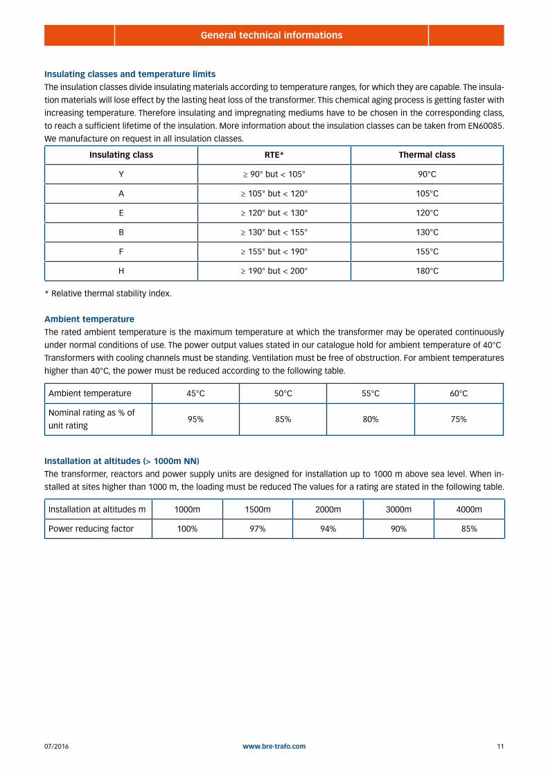
Insulating classes and temperature limits
The insulation classes divide insulating materials according to temperature ranges, for which they are capable. The insula-
tion materials will lose effect by the lasting heat loss of the transformer. This chemical aging process is getting faster with
increasing temperature. Therefore insulating and impregnating mediums have to be chosen in the corresponding class,
to reach a sufficient lifetime of the insulation. More information about the insulation classes can be taken from EN60085.
We manufacture on request in all insulation classes.
Insulating class RTE* Thermal class
Y ≥ 90° but < 105° 90°C
A ≥ 105° but < 120° 105°C
E ≥ 120° but < 130° 120°C
B ≥ 130° but < 155° 130°C
F ≥ 155° but < 190° 155°C
H ≥ 190° but < 200° 180°C
* Relative thermal stability index.
Ambient temperature
The rated ambient temperature is the maximum temperature at which the transformer may be operated continuously
under normal conditions of use. The power output values stated in our catalogue hold for ambient temperature of 40°C
Transformers with cooling channels must be standing. Ventilation must be free of obstruction. For ambient temperatures
higher than 40°C, the power must be reduced according to the following table.
Ambient temperature 45°C 50°C 55°C 60°C
Nominal rating as % of
unit rating95% 85% 80% 75%
Installation at altitudes (> 1000m NN)
The transformer, reactors and power supply units are designed for installation up to 1000 m above sea level. When in-
stalled at sites higher than 1000 m, the loading must be reduced The values for a rating are stated in the following table.
Installation at altitudes m 1000m 1500m 2000m 3000m 4000m
Power reducing factor 100% 97% 94% 90% 85%
07/201612 www.bre-trafo.com
General technical informations
Protection class
Transformers are classified according to their protection against electric shock.
Class I transformer is a transformer in which protection against electric shock does not rely on basic insulation only,
but which includes an additional safety precaution such as an earthing terminal.
Class II transformer is a transformer in which protection against electric shock does not rely on basic insulation only,
but in which additional safety precautions such as double insulation or reinforced insulation are provided, there being
no provision for protective earthing or reliance upon installation conditions.
Class III transformer is a transformer in which protection against electric shock relies on supply at SELV and in which
voltages higher than those of SELV are not generated.
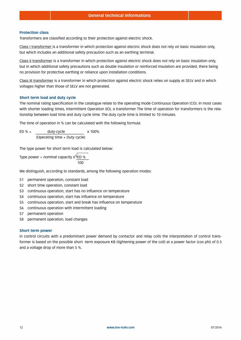
Short term load and duty cycle
The nominal rating specification in the catalogue relate to the operating mode Continuous Operation (CO). In most cases
with shorter loading times, Intermittent Operation (IO), a transformer The time of operation for transformers is the rela-
tionship between load time and duty cycle time. The duty cycle time is limited to 10 minutes.
The time of operation in % can be calculated with the following formula:
ED % = duty-cycle x 100%
(Operating time + Duty cycle)
The type power for short term load is calculated below:
Type power = nominal capacity x ED %
100
We distinguish, according to standards, among the following operation modes:
S1 permanent operation, constant load
S2 short time operation, constant load
S3 continuous operation, start has no influence on temperature
S4 continuous operation, start has influence on temperature
S5 continuous operation, start and break has influence on temperature
S6 continuous operation with intermittent loading
S7 permanent operation
S8 permanent operation, load changes
Short term power
In control circuits with a predominant power demand by contactor and relay coils the interpretation of control trans-
former is based on the possible short -term exposure KB (tightening power of the coil) at a power factor (cos phi) of 0.5
and a voltage drop of more than 5 %.

1307/2016 www.bre-trafo.com
Definition of terms
Tap
Transformers can be executed on the input and output side with taps. Taps on the input side, for example, serve as the
adaptation and use of the transformer at different mains voltages.
Protection
Primary line protection (if required) interpret slow - rule of thumb 1.5 to 2 x rated current, secondary Always make sure
to protect nominal current (Starting current of the appliance eg. consider motor)
Connections
0 - 50A of standard transformer terminals, 50 - 340A terminal blocks on head angle, from 340A cable lugs or copper bars.
Different constructions possible, depending on manufacturing model.
Connected load
Information always as apparent power in VA o kVA at cos ϕ =1, otherwise active power in W o kW plus cos ϕ of the con-
nected machine , calculation 1ph transformer.. P = U x I: cos ϕ , 3ph-transformer P = U x I x √3 : cos ϕ
Non-inherently short-circuit proof transformer
This is a transformer that includes a protective device. For example, a fuse, an overcurrent release or a temperature lim-
iter, which opens the primary or secondary circuit , when the transformer is overloaded or short-circuited.
cos ϕ
Is determined by consumer, such as motor, contactor. At cos ϕ = 0,5 is the apparent power = 2 x active power),
Pschein x cos ϕ = Pwirk
iron losses
Are core losses (unmagnetization losses) and also occur in the unloaded transformer during operation. They are depen-
dent on the induction, power fluctuations (e.g. mains voltage +/- 10 %) and the frequency (eg 50Hz , 60Hz)
Inrush
Specifies the inrush current, which arise phase dependend at switch on. Transformers usually have an inrush between 8
and 20 times the rated current. However toroidals up to 80 times of the rated current. In consequence, high primary fuse
values are required. Countermeasures can be: Inrush current limiter , constructive measures of transformer calculation.
Fail-Safe-Transformer
This is a transformer that fails through improper use, but is not dangerous for the user or the environment.
Frequency
Determines the induction and iron losses, each 50Hz transformer can be operated at 60Hz. But not vice versa!
Separated Winding
For transformers with separate windings there is no conductive connection between individual windings, they are gal-
vanically isolated. The type power corresponds to the rated output power.
07/201614 www.bre-trafo.com
Definition of terms
Low voltage
Voltages under 50 volt
Low voltage (low tension)
Voltages from 51 up to 1000 Volt
High voltage
Voltages above 1000 volt
Copper weight
At the same frame size, can give information on the winding losses and the associated efficiency.
Short-circuit voltage (uk)
This is the voltage which has to be applied to the input winding, so that a short circuited output winding of the rated
output current flows. It is expressed in % of the rated input voltage.
Short-circuit proof transformer
Transformer in which the temperature does not exceed the specified limits when the transformer is overloaded or short-
circuit and which continues to meet all requirements of this standard after the removal of the overload or short-circuit.
Non-short-circuit proof transformer
A transformer which is intended to be protected against excessive temperature by means of a protective device not
provided with the transformer and which continues to meet all the requirements of this standard after the removal of the
overload or short-circuit and resetting of the protective device.
No-load output voltage (U0)
The output voltage when the transformer is connected to rated supply voltage at rated frequency with no-load on the
output.
No-load current (I0)
The input current when the transformer is connected to rated supply voltage at rated frequency with no-load on the
output.
Autowindings
Autowindings are conducting connection between primary and secondary windings. In addition, autowindings occurs a
substantial material savings.
Vacuum impregnation
Protection against humidity and aggressive atmosphere. Bonds also the core sheets to each other and the windings with
each other and with their isolation. Therefore, a strong noise reduction and better thermal coupling of the winding can
be achieved.
Power losses of the transformer
The power losses of a transformer consists of iron losses (due to the induction and frequency) and copper losses (due to
the current through the coil and its temperature) together. Iron losses are idling losses and therefore always present. It
can be optimized through design and the type of core sheets. Copper losses are load-dependent, they are always speci-
fied at rated load or rated current and can be influenced by the quality of the winding and amount of the copper weight.

1507/2016 www.bre-trafo.com
1 | SINGLE-PHASE TRANSFORMERS
BSV Control transformers, low losses ........................................................................................................................ 18 BS Control transformers, cost optimized ................................................................................................................. 20 BEV Single-phase transformers, low losses, customer specific version ..................................................................... 22 BE Single-phase transformers, cost-optimized, customer specific version ............................................................. 23 BSUS Control transformers, UI, standing ...................................................................................................................... 24 BSUL Control transformers, UI, lying ............................................................................................................................ 25 BEUT Single-phase universal transformers ................................................................................................................... 26 BUF Single-phase transformers, UI, cost-optimized, customer specific version ........................................................ 27 BUVA Single-phase transformers, UI, low losses, customer specific version ................................................................ 28 BUH Single-phase transformers, UI, cost-optimized, customer specific version ........................................................ 29 BELT Single-phase auto transformers (for fan and motor regulation) ......................................................................... 30 BBIT Building sites insulating isolation transformer .................................................................................................... 31 BMED Single-phase isolating transformer for supply of medical rooms ....................................................................... 32 BOPL Single-phase isolating transformer for supply of surgical lights ......................................................................... 33

07/201616 www.bre-trafo.com
Notes

1707/2016 www.bre-trafo.com
1 | Single-phase transformers
Company _________________________________________________________________________________
Street adress _________________________________________________________________________________
Zip code, city _________________________________________________________________________________
Contact person _________________________________________________________________________________
Phone _________________________________________________________________________________
Mail _________________________________________________________________________________
Units _________________________________________________________________________________
Isolating transformer Safety transformer Auto transformer Control transformer
Other _________________________________________________________________________________
Power _________________________________________________________________________________
Input voltage _________________________________________________________________________________
Input current _________________________________________________________________________________
Output voltage _________________________________________________________________________________
Output current _________________________________________________________________________________
Duty cycle S1 / 100% ED Others ________________________________________________
Frequency 50/60 Hz 60 Hz Others _________________________________
Temperature class ta 40°C/E ta 40°C/B ta 40°C/F Others _______________
Protection class IP xx B (IP 00) IP 23 IP 54 Casting
Others ______________
Housing color RAL 7035 RAL 7032 Others ________________________________
Standards EN 61558 UL/CSA Others ________________________________
Primary connection Terminals ___mm² Solder lug Free ends Others _______________
Secondary connection Terminals ___mm² Solder lug Free ends Others _______________
Attachment Foot angle Foot bar Catch spring Studs
Documentation inspection record Data sheet Circuit diagram Serial numbers
Appointment _________________________________________________________________________________
Others _________________________________________________________________________________
Application form for customized single-phase transformers

07/201618 www.bre-trafo.com
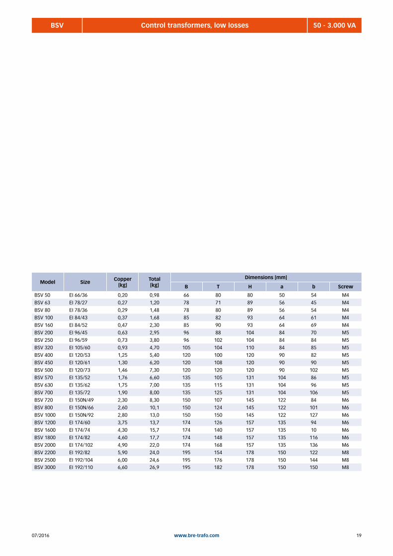
BSV 50 - 3.000 VAControl transformers, low losses
General characteristics:• control transformer with standard voltages
• energy efficient with grain oriented sheet (M165-35A)
• nested mutually
• high overload capability
• voltage adjustment through tappings on the input side +-5%
• open design for stationary installation
• back of hand and finger contact protected terminals, according to
DGUV, Rule 3
• IP xx B, insulation class B, max ambient temperature ta 40°C
(ta 40°C/B
• UL approval (UL5085 - XPTQ2) as standard)
Standard voltages:AC 220/230/240V // AC 24V (up to 1200VA)
AC 220/230/240V // AC 230V
AC 380/400/420V // AC 24V (up to 1200VA)
AC 380/400/420V // AC 230V
AC 440/460/480/500V // AC 24V (up to 1200VA)
AC 440/460/480/500V // AC 230V
Standards:EN 61558-2-2 Control transformers
EN 61558-2-4 Isolation transformer
EN 61558-2-6 Safety transformer
UL 5085 Low voltage transfomers (XPTQ2)
Model Power [VA]
230 // 24 V Art.-No.
230 // 230 VArt.-No.
400 // 24 VArt.-No.
400 // 230 V Art.-No.
500 // 24 VArt.-No.
500 // 230 VArt.-No.
BSV 50 50 0500-10-000050 0501-10-000050 0502-10-000050 0503-10-000050 0504-10-000050 0505-10-000050
BSV 63 63 0500-10-000063 0501-10-000063 0502-10-000063 0503-10-000063 0504-10-000063 0505-10-000063
BSV 80 80 0500-10-000080 0501-10-000080 0502-10-000080 0503-10-000080 0504-10-000080 0505-10-000080
BSV 100 100 0500-10-000100 0501-10-000100 0502-10-000100 0503-10-000100 0504-10-000100 0505-10-000100
BSV 160 160 0500-10-000160 0501-10-000160 0502-10-000160 0503-10-000160 0504-10-000160 0505-10-000160
BSV 200 200 0500-10-000200 0501-10-000200 0502-10-000200 0503-10-000200 0504-10-000200 0505-10-000200
BSV 250 250 0500-10-000250 0501-10-000250 0502-10-000250 0503-10-000250 0504-10-000250 0505-10-000250
BSV 320 320 0500-10-000320 0501-10-000320 0502-10-000320 0503-10-000320 0504-10-000320 0505-10-000320
BSV 400 400 0500-10-000400 0501-10-000400 0502-10-000400 0503-10-000400 0504-10-000400 0505-10-000400
BSV 450 450 0500-10-000450 0501-10-000450 0502-10-000450 0503-10-000450 0504-10-000450 0505-10-000450
BSV 500 500 0500-10-000500 0501-10-000500 0502-10-000500 0503-10-000500 0504-10-000500 0505-10-000500
BSV 570 570 0500-10-000570 0501-10-000570 0502-10-000570 0503-10-000570 0504-10-000570 0505-10-000570
BSV 630 630 0500-10-000630 0501-10-000630 0502-10-000630 0503-10-000630 0504-10-000630 0505-10-000630
BSV 700 700 0500-10-000700 0501-10-000700 0502-10-000700 0503-10-000700 0504-10-000700 0505-10-000700
BSV 720 720 0500-10-000720 0501-10-000720 0502-10-000720 0503-10-000720 0504-10-000720 0505-10-000720
BSV 800 800 0500-10-000800 0501-10-000800 0502-10-000800 0503-10-000800 0504-10-000800 0505-10-000800
BSV 1000 1000 0500-10-001000 0501-10-001000 0502-10-001000 0503-10-001000 0504-10-001000 0505-10-001000
BSV 1200 1200 0500-10-001200 0501-10-001200 0502-10-001200 0503-10-001200 0504-10-001200 0505-10-001200
BSV 1600 1600 --- 0501-10-001600 --- 0503-10-001600 --- 0505-10-001600
BSV 1800 1800 --- 0501-10-001800 --- 0503-10-001800 --- 0505-10-001800
BSV 2000 2000 --- 0501-10-002000 --- 0503-10-002000 --- 0505-10-002000
BSV 2200 2200 --- 0501-10-002200 --- 0503-10-002200 --- 0505-10-002200
BSV 2500 2500 --- 0501-10-002500 --- 0503-10-002500 --- 0505-10-002500
BSV 3000 3000 --- 0501-10-003000 --- 0503-10-003000 --- 0505-10-003000
1907/2016 www.bre-trafo.com
Model Size Copper[kg]
Total [kg]
Dimensions [mm]
B T H a b Screw
BSV 50 EI 66/36 0,20 0,98 66 80 80 50 54 M4
BSV 63 EI 78/27 0,27 1,20 78 71 89 56 45 M4
BSV 80 EI 78/36 0,29 1,48 78 80 89 56 54 M4
BSV 100 EI 84/43 0,37 1,68 85 82 93 64 61 M4
BSV 160 EI 84/52 0,47 2,30 85 90 93 64 69 M4
BSV 200 EI 96/45 0,63 2,95 96 88 104 84 70 M5
BSV 250 EI 96/59 0,73 3,80 96 102 104 84 84 M5
BSV 320 EI 105/60 0,93 4,70 105 104 110 84 85 M5
BSV 400 EI 120/53 1,25 5,40 120 100 120 90 82 M5
BSV 450 EI 120/61 1,30 6,20 120 108 120 90 90 M5
BSV 500 EI 120/73 1,46 7,30 120 120 120 90 102 M5
BSV 570 EI 135/52 1,76 6,60 135 105 131 104 86 M5
BSV 630 EI 135/62 1,75 7,00 135 115 131 104 96 M5
BSV 700 EI 135/72 1,90 8,00 135 125 131 104 106 M5
BSV 720 EI 150N/49 2,30 8,30 150 107 145 122 84 M6
BSV 800 EI 150N/66 2,60 10,1 150 124 145 122 101 M6
BSV 1000 EI 150N/92 2,80 13,0 150 150 145 122 127 M6
BSV 1200 EI 174/60 3,75 13,7 174 126 157 135 94 M6
BSV 1600 EI 174/74 4,30 15,7 174 140 157 135 10 M6
BSV 1800 EI 174/82 4,60 17,7 174 148 157 135 116 M6
BSV 2000 EI 174/102 4,90 22,0 174 168 157 135 136 M6
BSV 2200 EI 192/82 5,90 24,0 195 154 178 150 122 M8
BSV 2500 EI 192/104 6,00 24,6 195 176 178 150 144 M8BSV 3000 EI 192/110 6,60 26,9 195 182 178 150 150 M8
BSV 50 - 3.000 VAControl transformers, low losses

07/201620 www.bre-trafo.com
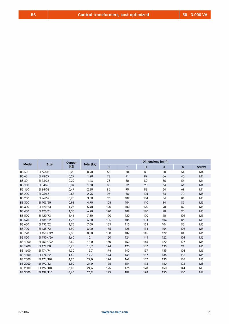
BS 50 - 3.000 VAControl transformers, cost optimized
General characteristics:• control transformer with standard voltages
• cost optimized
• welded
• voltage adjustment through +- % 5 tappings on the input side
• open design for stationary installation
• back of hand and finger contact protected terminals, according to
DGUV rule 3
• IP xx B, insulation class B, max ambient temperature 40°C
(ta 40°C/B)
• 50-250 VA versions with combined mounting plate
• UL approval (UL5085 - XPTQ2) as standard
Standard voltages:AC 220/230/240V // AC 24V (up to 1200VA)
AC 220/230/240V // AC 230V
AC 380/400/420V // AC 24V (up to 1200VA)
AC 380/400/420V // AC 230V
AC 440/460/480/500V // AC 24V (up to 1200VA)
AC 440/460/480/500V // AC 230V
Standards:EN 61558-2-2 Control transformers
EN 61558-2-4 Isolation transformer
EN 61558-2-6 Safety transformer
UL 5085 Low voltage transfomers (XPTQ2)
Model Power [VA]
230 // 24 V Art.-No.
230 // 230 VArt.-No.
400 // 24 VArt.-No.
400 // 230 V Art.-No.
500 // 24 VArt.-No.
500 // 230 VArt.-No.
BS 50 50 0510-10-000050 0511-10-000050 0512-10-000050 0513-10-000050 0514-10-000050 0515-10-000050
BS 63 63 0510-10-000063 0511-10-000063 0512-10-000063 0513-10-000063 0514-10-000063 0515-10-000063
BS 80 80 0510-10-000080 0511-10-000080 0512-10-000080 0513-10-000080 0514-10-000080 0515-10-000080
BS 100 100 0510-10-000100 0511-10-000100 0512-10-000100 0513-10-000100 0514-10-000100 0515-10-000100
BS 160 160 0510-10-000160 0511-10-000160 0512-10-000160 0513-10-000160 0514-10-000160 0515-10-000160
BS 200 200 0510-10-000200 0511-10-000200 0512-10-000200 0513-10-000200 0514-10-000200 0515-10-000200
BS 250 250 0510-10-000250 0511-10-000250 0512-10-000250 0513-10-000250 0514-10-000250 0515-10-000250
BS 320 320 0510-10-000320 0511-10-000320 0512-10-000320 0513-10-000320 0514-10-000320 0515-10-000320
BS 400 400 0510-10-000400 0511-10-000400 0512-10-000400 0513-10-000400 0514-10-000400 0515-10-000400
BS 450 450 0510-10-000450 0511-10-000450 0512-10-000450 0513-10-000450 0514-10-000450 0515-10-000450
BS 500 500 0510-10-000500 0511-10-000500 0512-10-000500 0513-10-000500 0514-10-000500 0515-10-000500
BS 570 570 0510-10-000570 0511-10-000570 0512-10-000570 0513-10-000570 0514-10-000570 0515-10-000570
BS 630 630 0510-10-000630 0511-10-000630 0512-10-000630 0513-10-000630 0514-10-000630 0515-10-000630
BS 700 700 0510-10-000700 0511-10-000700 0512-10-000700 0513-10-000700 0514-10-000700 0515-10-000700
BS 720 720 0510-10-000720 0511-10-000720 0512-10-000720 0513-10-000720 0514-10-000720 0515-10-000720
BS 800 800 0510-10-000800 0511-10-000800 0512-10-000800 0513-10-000800 0514-10-000800 0515-10-000800
BS 1000 1000 0510-10-001000 0511-10-001000 0512-10-001000 0513-10-001000 0514-10-001000 0515-10-001000
BS 1200 1200 0510-10-001200 0511-10-001200 0512-10-001200 0513-10-001200 0514-10-001200 0515-10-001200
BS 1600 1600 --- 0511-10-001600 --- 0513-10-001600 --- 0515-10-001600
BS 1800 1800 --- 0511-10-001800 --- 0513-10-001800 --- 0515-10-001800
BS 2000 2000 --- 0511-10-002000 --- 0513-10-002000 --- 0515-10-002000
BS 2200 2200 --- 0511-10-002200 --- 0513-10-002200 --- 0515-10-002200
BS 2500 2500 --- 0511-10-002500 --- 0513-10-002500 --- 0515-10-002500
BS 3000 3000 --- 0511-10-003000 --- 0513-10-003000 --- 0515-10-003000
2107/2016 www.bre-trafo.com
Model Size Copper [kg] Total [kg]
Dimensions [mm]
B T H a b Screw
BS 50 EI 66/36 0,20 0,98 66 80 80 50 54 M4
BS 63 EI 78/27 0,27 1,20 78 71 89 56 45 M4
BS 80 EI 78/36 0,29 1,48 78 80 89 56 54 M4
BS 100 EI 84/43 0,37 1,68 85 82 93 64 61 M4
BS 160 EI 84/52 0,47 2,30 85 90 93 64 69 M4
BS 200 EI 96/45 0,63 2,95 96 88 104 84 70 M5
BS 250 EI 96/59 0,73 3,80 96 102 104 84 84 M5
BS 320 EI 105/60 0,93 4,70 105 104 110 84 85 M5
BS 400 EI 120/53 1,25 5,40 120 100 120 90 82 M5
BS 450 EI 120/61 1,30 6,20 120 108 120 90 90 M5
BS 500 EI 120/73 1,46 7,30 120 120 120 90 102 M5
BS 570 EI 135/52 1,76 6,60 135 105 131 104 86 M5
BS 630 EI 135/62 1,75 7,00 135 115 131 104 96 M5
BS 700 EI 135/72 1,90 8,00 135 125 131 104 106 M5
BS 720 EI 150N/49 2,30 8,30 150 107 145 122 84 M6
BS 800 EI 150N/66 2,60 10,1 150 124 145 122 101 M6
BS 1000 EI 150N/92 2,80 13,0 150 150 145 122 127 M6
BS 1200 EI 174/60 3,75 13,7 174 126 157 135 94 M6
BS 1600 EI 174/74 4,30 15,7 174 140 157 135 108 M6
BS 1800 EI 174/82 4,60 17,7 174 148 157 135 116 M6
BS 2000 EI 174/102 4,90 22,0 174 168 157 135 136 M6
BS 2200 EI 192/82 5,90 24,0 195 154 178 150 122 M8
BS 2500 EI 192/104 6,00 24,6 195 176 178 150 144 M8BS 3000 EI 192/110 6,60 26,9 195 182 178 150 150 M8
BS 50 - 3.000 VAControl transformers, cost optimized

07/201622 www.bre-trafo.com
BEV 25 - 3.000 VASingle-phase transformers, low losses, customer specific version
General characteristics:• transformer with customized voltages
• energy efficiency with grain oriented sheet
• nested mutually
• high overload capability
• open design for stationary installation
• back of hand and finger contact protected terminals, according
to DGUV rule 3
• IP xx B, insulation class B, max ambient temperature 40°C (ta 40°C/B)
• available in several standards
• UL approval (UL5085 - XPTQ2) available on request
Standards:EN 61558-2-2 Control transformers
EN 61558-2-4 Isolation transformer
EN 61558-2-6 Safety transformer
EN 61558-2-13 Auto transformers
UL 5085 Low voltage transfomers (XPTQ2)
Model Art.-No. Power [VA] Size Copper
[kg] Total [kg]
Dimensions [mm]
B T H a b Screw
BEV 25 0520-20-xxxxxx 25 EI 60/21 0,13 0,50 60 65 76 44 36 M3
BEV 35 0520-20-xxxxxx 35 EI 60/31 0,14 0,52 60 75 76 44 46 M3
BEV 50 0520-20-xxxxxx 50 EI 66/36 0,20 0,98 66 80 80 50 54 M4
BEV 63 0520-20-xxxxxx 63 EI 78/27 0,27 1,20 78 71 89 56 45 M4
BEV 80 0520-20-xxxxxx 80 EI 78/36 0,29 1,48 78 80 89 56 54 M4
BEV 100 0520-20-xxxxxx 100 EI 84/43 0,37 1,68 85 68 93 64 47 M4
BEV 160 0520-20-xxxxxx 160 EI 84/52 0,47 2,30 85 90 93 64 69 M4
BEV 161 0520-20-xxxxxx 160 EI 96/35 0,57 2,38 96 78 104 84 60 M5
BEV 200 0520-20-xxxxxx 200 EI 96/45 0,63 2,95 96 88 104 84 70 M5
BEV 201 0520-20-xxxxxx 200 EI 105/37 0,71 3,20 105 80 110 84 62 M5
BEV 250 0520-20-xxxxxx 250 EI 96/59 0,73 3,80 96 102 104 84 84 M5
BEV 270 0520-20-xxxxxx 270 EI 105/45 0,85 3,70 105 88 110 84 69 M5
BEV 320 0520-20-xxxxxx 320 EI 105/60 0,93 4,70 105 104 110 84 85 M5
BEV 321 0520-20-xxxxxx 320 EI 120/41 1,15 4,30 120 88 121 90 70 M5
BEV 400 0520-20-xxxxxx 400 EI 120/53 1,25 5,40 120 100 120 90 82 M5
BEV 450 0520-20-xxxxxx 450 EI 120/61 1,30 6,20 120 108 120 90 90 M5
BEV 500 0520-20-xxxxxx 500 EI 120/73 1,46 7,30 120 120 120 90 102 M5
BEV 570 0520-20-xxxxxx 570 EI 135/52 1,76 6,60 135 105 131 104 86 M5
BEV 630 0520-20-xxxxxx 630 EI 135/62 1,75 7,00 135 115 131 104 96 M5
BEV 700 0520-20-xxxxxx 700 EI 135/72 1,90 8,00 135 125 131 104 106 M5
BEV 720 0520-20-xxxxxx 720 EI 150N/49 2,30 8,30 150 107 145 122 84 M6
BEV 800 0520-20-xxxxxx 800 EI 150N/66 2,60 10,1 150 124 145 122 101 M6
BEV 1000 0520-20-xxxxxx 1000 EI 150N/92 2,80 13,0 150 150 145 122 127 M6
BEV 1200 0520-20-xxxxxx 1200 EI 174/60 3,75 13,7 174 126 157 135 94 M6
BEV 1600 0520-20-xxxxxx 1600 EI 174/74 4,30 15,7 174 140 157 135 108 M6
BEV 1800 0520-20-xxxxxx 1800 EI 174/82 4,60 17,7 174 148 157 135 116 M6
BEV 2000 0520-20-xxxxxx 2000 EI 174/102 4,90 22,0 174 168 157 135 136 M6
BEV 2001 0520-20-xxxxxx 2000 EI 192/70 5,40 23,0 195 142 178 150 110 M8
BEV 2200 0520-20-xxxxxx 2200 EI 192/82 5,90 24,0 195 154 178 150 122 M8
BEV 2500 0520-20-xxxxxx 2500 EI 192/104 6,00 24,6 195 176 178 150 144 M8BEV 3000 0520-20-xxxxxx 3000 EI 192/110 6,60 26,9 195 182 178 150 150 M8

2307/2016 www.bre-trafo.com
BE 25 - 3.000 VASingle-phase transformers, cost optimized, customer specific version
General characteristics:• transformer with customized voltages
• cost optimized
• welded
• open design for stationary installation
• back of hand and finger contact protected terminals, according
to DGUV rule 3
• IP xx B, insulation class B, max ambient temperature
40°C (ta 40°C/B)
• available in several standards
• 50-250 VA versions with combined mounting plate
• UL approval (UL5085 - XPTQ2) available on request
Standards:EN 61558-2-2 Control transformers
EN 61558-2-4 Isolation transformer
EN 61558-2-6 Safety transformer
EN 61558-2-13 Auto transformers
UL 5085 Low voltage transfomers (XPTQ2)
Model Art.-No. Power [VA] Size Copper
[kg] Total [kg]
Dimensions [mm]
B T H a b Screw
BE 25 0521-20-xxxxxx 25 EI 60/21 0,13 0,50 60 65 76 44 36 M3
BE 35 0521-20-xxxxxx 35 EI 60/31 0,14 0,52 60 75 76 44 46 M3
BE 50 0521-20-xxxxxx 50 EI 66/36 0,20 0,98 66 80 80 50 54 M4
BE 63 0521-20-xxxxxx 63 EI 78/27 0,27 1,20 78 71 89 56 45 M4
BE 80 0521-20-xxxxxx 80 EI 78/36 0,29 1,48 78 80 89 56 54 M4
BE 100 0521-20-xxxxxx 100 EI 84/43 0,37 1,68 85 68 93 64 47 M4
BE 160 0521-20-xxxxxx 160 EI 84/52 0,47 2,30 85 90 93 64 69 M4
BE 161 0521-20-xxxxxx 160 EI 96/35 0,57 2,38 96 78 104 84 60 M5
BE 200 0521-20-xxxxxx 200 EI 96/45 0,63 2,95 96 88 104 84 70 M5
BE 201 0521-20-xxxxxx 200 EI 105/37 0,71 3,20 105 80 110 84 62 M5
BE 250 0521-20-xxxxxx 250 EI 96/59 0,73 3,80 96 102 104 84 84 M5
BE 270 0521-20-xxxxxx 270 EI 105/45 0,85 3,70 105 88 110 84 69 M5
BE 320 0521-20-xxxxxx 320 EI 105/60 0,93 4,70 105 104 110 84 85 M5
BE 321 0521-20-xxxxxx 320 EI 120/41 1,15 4,30 120 88 121 90 70 M5
BE 400 0521-20-xxxxxx 400 EI 120/53 1,25 5,40 120 100 120 90 82 M5
BE 450 0521-20-xxxxxx 450 EI 120/61 1,30 6,20 120 108 120 90 90 M5
BE 500 0521-20-xxxxxx 500 EI 120/73 1,46 7,30 120 120 120 90 102 M5
BE 570 0521-20-xxxxxx 570 EI 135/52 1,76 6,60 135 105 131 104 86 M5
BE 630 0521-20-xxxxxx 630 EI 135/62 1,75 7,00 135 115 131 104 96 M5
BE 700 0521-20-xxxxxx 700 EI 135/72 1,90 8,00 135 125 131 104 106 M5
BE 720 0521-20-xxxxxx 720 EI 150N/49 2,30 8,30 150 107 145 122 84 M6
BE 800 0521-20-xxxxxx 800 EI 150N/66 2,60 10,1 150 124 145 122 101 M6
BE 1000 0521-20-xxxxxx 1000 EI 150N/92 2,80 13,0 150 150 145 122 127 M6
BE 1200 0521-20-xxxxxx 1200 EI 174/60 3,75 13,7 174 126 157 135 94 M6
BE 1600 0521-20-xxxxxx 1600 EI 174/74 4,30 15,7 174 140 157 135 108 M6
BE 1800 0521-20-xxxxxx 1800 EI 174/82 4,60 17,7 174 148 157 135 116 M6
BE 2000 0521-20-xxxxxx 2000 EI 174/102 4,90 22,0 174 168 157 135 136 M6
BE 2001 0521-20-xxxxxx 2000 EI 192/70 5,40 23,0 195 142 178 150 110 M8
BE 2200 0521-20-xxxxxx 2200 EI 192/82 5,90 24,0 195 154 178 150 122 M8
BE 2500 0521-20-xxxxxx 2500 EI 192/104 6,00 24,6 195 176 178 150 144 M8BE 3000 0521-20-xxxxxx 3000 EI 192/110 6,60 26,9 195 182 178 150 150 M8
07/201624 www.bre-trafo.com
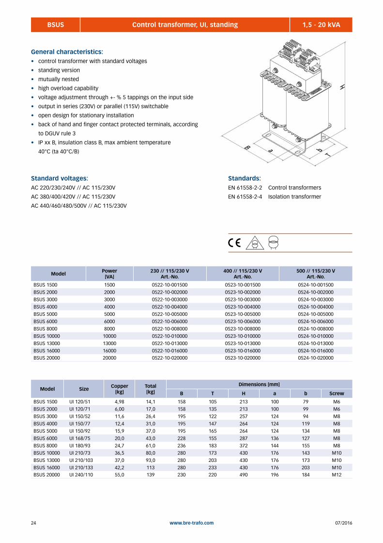
BSUS 1,5 - 20 kVAControl transformer, UI, standing
General characteristics:• control transformer with standard voltages
• standing version
• mutually nested
• high overload capability
• voltage adjustment through +- % 5 tappings on the input side
• output in series (230V) or parallel (115V) switchable
• open design for stationary installation
• back of hand and finger contact protected terminals, according
to DGUV rule 3
• IP xx B, insulation class B, max ambient temperature
40°C (ta 40°C/B)
Standard voltages:AC 220/230/240V // AC 115/230V
AC 380/400/420V // AC 115/230V
AC 440/460/480/500V // AC 115/230V
Standards:EN 61558-2-2 Control transformers
EN 61558-2-4 Isolation transformer
Model Size Copper [kg]
Total [kg]
Dimensions [mm]
B T H a b Screw
BSUS 1500 UI 120/51 4,98 14,1 158 105 213 100 79 M6
BSUS 2000 UI 120/71 6,00 17,0 158 135 213 100 99 M6
BSUS 3000 UI 150/52 11,6 26,4 195 122 257 124 94 M8
BSUS 4000 UI 150/77 12,4 31,0 195 147 264 124 119 M8
BSUS 5000 UI 150/92 15,9 37,0 195 165 264 124 134 M8
BSUS 6000 UI 168/75 20,0 43,0 228 155 287 136 127 M8
BSUS 8000 UI 180/93 24,7 61,0 236 183 372 144 155 M8
BSUS 10000 UI 210/73 36,5 80,0 280 173 430 176 143 M10
BSUS 13000 UI 210/103 37,0 93,0 280 203 430 176 173 M10
BSUS 16000 UI 210/133 42,2 113 280 233 430 176 203 M10BSUS 20000 UI 240/110 55,0 139 230 220 490 196 184 M12
Model Power [VA]
230 // 115/230 V Art.-No.
400 // 115/230 VArt.-No.
500 // 115/230 V Art.-No.
BSUS 1500 1500 0522-10-001500 0523-10-001500 0524-10-001500
BSUS 2000 2000 0522-10-002000 0523-10-002000 0524-10-002000
BSUS 3000 3000 0522-10-003000 0523-10-003000 0524-10-003000
BSUS 4000 4000 0522-10-004000 0523-10-004000 0524-10-004000
BSUS 5000 5000 0522-10-005000 0523-10-005000 0524-10-005000
BSUS 6000 6000 0522-10-006000 0523-10-006000 0524-10-006000
BSUS 8000 8000 0522-10-008000 0523-10-008000 0524-10-008000
BSUS 10000 10000 0522-10-010000 0523-10-010000 0524-10-010000
BSUS 13000 13000 0522-10-013000 0523-10-013000 0524-10-013000
BSUS 16000 16000 0522-10-016000 0523-10-016000 0524-10-016000BSUS 20000 20000 0522-10-020000 0523-10-020000 0524-10-020000
2507/2016 www.bre-trafo.com
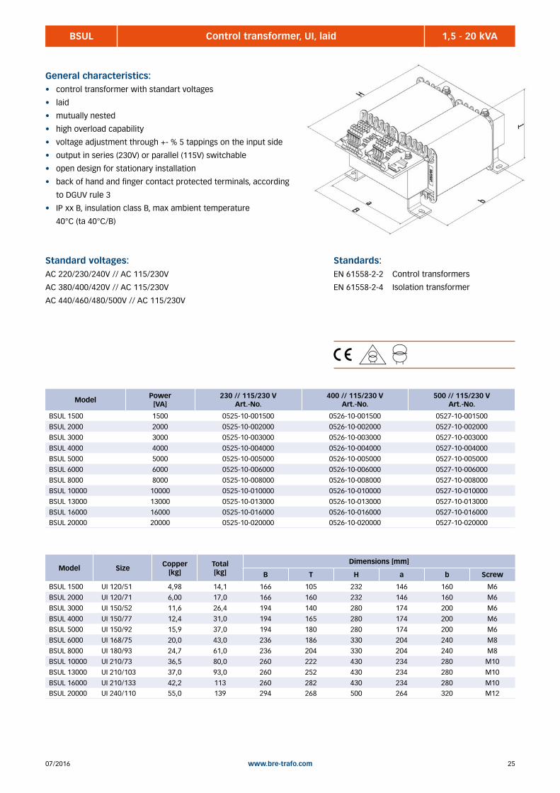
BSUL 1,5 - 20 kVAControl transformer, UI, laid
General characteristics:• control transformer with standart voltages
• laid
• mutually nested
• high overload capability
• voltage adjustment through +- % 5 tappings on the input side
• output in series (230V) or parallel (115V) switchable
• open design for stationary installation
• back of hand and finger contact protected terminals, according
to DGUV rule 3
• IP xx B, insulation class B, max ambient temperature
40°C (ta 40°C/B)
Standard voltages:AC 220/230/240V // AC 115/230V
AC 380/400/420V // AC 115/230V
AC 440/460/480/500V // AC 115/230V
Standards:EN 61558-2-2 Control transformers
EN 61558-2-4 Isolation transformer
Model Size Copper [kg]
Total [kg]
Dimensions [mm]
B T H a b Screw
BSUL 1500 UI 120/51 4,98 14,1 166 105 232 146 160 M6
BSUL 2000 UI 120/71 6,00 17,0 166 160 232 146 160 M6
BSUL 3000 UI 150/52 11,6 26,4 194 140 280 174 200 M6
BSUL 4000 UI 150/77 12,4 31,0 194 165 280 174 200 M6
BSUL 5000 UI 150/92 15,9 37,0 194 180 280 174 200 M6
BSUL 6000 UI 168/75 20,0 43,0 236 186 330 204 240 M8
BSUL 8000 UI 180/93 24,7 61,0 236 204 330 204 240 M8
BSUL 10000 UI 210/73 36,5 80,0 260 222 430 234 280 M10
BSUL 13000 UI 210/103 37,0 93,0 260 252 430 234 280 M10
BSUL 16000 UI 210/133 42,2 113 260 282 430 234 280 M10BSUL 20000 UI 240/110 55,0 139 294 268 500 264 320 M12
Model Power [VA]
230 // 115/230 V Art.-No.
400 // 115/230 VArt.-No.
500 // 115/230 V Art.-No.
BSUL 1500 1500 0525-10-001500 0526-10-001500 0527-10-001500
BSUL 2000 2000 0525-10-002000 0526-10-002000 0527-10-002000
BSUL 3000 3000 0525-10-003000 0526-10-003000 0527-10-003000
BSUL 4000 4000 0525-10-004000 0526-10-004000 0527-10-004000
BSUL 5000 5000 0525-10-005000 0526-10-005000 0527-10-005000
BSUL 6000 6000 0525-10-006000 0526-10-006000 0527-10-006000
BSUL 8000 8000 0525-10-008000 0526-10-008000 0527-10-008000
BSUL 10000 10000 0525-10-010000 0526-10-010000 0527-10-010000
BSUL 13000 13000 0525-10-013000 0526-10-013000 0527-10-013000
BSUL 16000 16000 0525-10-016000 0526-10-016000 0527-10-016000BSUL 20000 20000 0525-10-020000 0526-10-020000 0527-10-020000
07/201626 www.bre-trafo.com
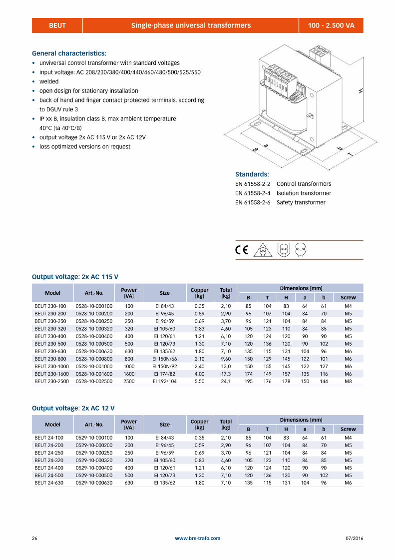
BEUT 100 - 2.500 VASingle-phase universal transformers
General characteristics:• unviversal control transformer with standard voltages
• input voltage: AC 208/230/380/400/440/460/480/500/525/550
• welded
• open design for stationary installation
• back of hand and finger contact protected terminals, according
to DGUV rule 3
• IP xx B, insulation class B, max ambient temperature
40°C (ta 40°C/B)
• output voltage 2x AC 115 V or 2x AC 12V
• loss optimized versions on request
Standards:EN 61558-2-2 Control transformers
EN 61558-2-4 Isolation transformer
EN 61558-2-6 Safety transformer
Model Art.-No. Power [VA] Size Copper
[kg] Total [kg]
Dimensions [mm]
B T H a b Screw
BEUT 230-100 0528-10-000100 100 EI 84/43 0,35 2,10 85 104 83 64 61 M4
BEUT 230-200 0528-10-000200 200 EI 96/45 0,59 2,90 96 107 104 84 70 M5
BEUT 230-250 0528-10-000250 250 EI 96/59 0,69 3,70 96 121 104 84 84 M5
BEUT 230-320 0528-10-000320 320 EI 105/60 0,83 4,60 105 123 110 84 85 M5
BEUT 230-400 0528-10-000400 400 EI 120/61 1,21 6,10 120 124 120 90 90 M5
BEUT 230-500 0528-10-000500 500 EI 120/73 1,30 7,10 120 136 120 90 102 M5
BEUT 230-630 0528-10-000630 630 EI 135/62 1,80 7,10 135 115 131 104 96 M6
BEUT 230-800 0528-10-000800 800 EI 150N/66 2,10 9,60 150 129 145 122 101 M6
BEUT 230-1000 0528-10-001000 1000 EI 150N/92 2,40 13,0 150 155 145 122 127 M6
BEUT 230-1600 0528-10-001600 1600 EI 174/82 4,00 17,3 174 149 157 135 116 M6BEUT 230-2500 0528-10-002500 2500 EI 192/104 5,50 24,1 195 176 178 150 144 M8
Model Art.-No. Power [VA] Size Copper
[kg] Total [kg]
Dimensions [mm]
B T H a b Screw
BEUT 24-100 0529-10-000100 100 EI 84/43 0,35 2,10 85 104 83 64 61 M4
BEUT 24-200 0529-10-000200 200 EI 96/45 0,59 2,90 96 107 104 84 70 M5
BEUT 24-250 0529-10-000250 250 EI 96/59 0,69 3,70 96 121 104 84 84 M5
BEUT 24-320 0529-10-000320 320 EI 105/60 0,83 4,60 105 123 110 84 85 M5
BEUT 24-400 0529-10-000400 400 EI 120/61 1,21 6,10 120 124 120 90 90 M5
BEUT 24-500 0529-10-000500 500 EI 120/73 1,30 7,10 120 136 120 90 102 M5BEUT 24-630 0529-10-000630 630 EI 135/62 1,80 7,10 135 115 131 104 96 M6
Output voltage: 2x AC 115 V
Output voltage: 2x AC 12 V

2707/2016 www.bre-trafo.com
BUF 250 VA - 100 kVASingle-phase transformers, UI, cost optimized, customer specific version
General characteristics:• transformer with customized voltages
• cost optimized
• open design for stationary installation
• back of hand and finger contact protected terminals, according
to DGUV rule 3
• up to 50A connection to transformer terminals, up top 340A
terminals, above copper bars or cable lugs
• IP xx B, insulation class B up to 5000 VA ambient temperature
40°C (ta 40°C/F)
• Insulation class F from 6000 VA, max ambient temperature 40°C
(ta 40°C/F)
• standard: standing constructed, other standards on request
• low losses versions, see BUVA or BUVU series
• available in various standards
Standards:EN 61558-2-2 Control transformers
EN 61558-2-4 Isolation transformer
EN 61558-2-6 Safety transformer
EN 61558-2-13 Auto transformers
Model Art.-No. Power [VA] Size Copper
[kg] Total [kg]
Dimensions [mm]
B T H a b Screw
BUF 250 0530-20-xxxxxxx 250 UI 75/26 1,20 3,00 100 66 132 63 49 M5
BUF 500 0530-20-xxxxxxx 500 UI 90/31 2,10 5,00 120 75 157 76 56 M6
BUF 750 0530-20-xxxxxxx 750 UI 90/51 2,50 7,00 120 95 157 76 76 M6
BUF 1000 0530-20-xxxxxxx 1.000 UI 120/41 4,70 11,0 158 95 213 100 89 M6
BUF 1500 0530-20-xxxxxxx 1.500 UI 120/51 5,10 14,0 158 105 213 100 79 M6
BUF 2000 0530-20-xxxxxxx 2.000 UI 120/71 6,00 17,0 158 135 213 100 99 M6
BUF 3000 0530-20-xxxxxxx 3.000 UI 150/52 12,0 27,0 195 122 257 124 94 M8
BUF 4000 0530-20-xxxxxxx 4.000 UI 150/77 13,0 31,0 195 147 264 124 119 M8
BUF 5000 0530-20-xxxxxxx 5.000 UI 150/92 16,0 37,0 195 165 264 124 134 M8
BUF 6000 0530-20-xxxxxxx 6.000 UI 180/63 17,0 39,0 236 153 372 144 125 M8
BUF 8000 0530-20-xxxxxxx 8.000 UI 180/78 24,0 48,0 236 168 372 144 140 M8
BUF 10000 0530-20-xxxxxxx 10.000 UI 210/63 36,0 63,0 280 163 430 176 133 M10
BUF 13000 0530-20-xxxxxxx 13.000 UI 210/88 37,0 75,0 280 188 430 176 158 M10
BUF 16000 0530-20-xxxxxxx 16.000 UI 210/103 40,0 86,0 280 203 430 176 173 M10
BUF 20000 0530-20-xxxxxxx 20.000 UI 240/110 51,0 121 320 220 490 196 184 M12
BUF 25000 0530-20-xxxxxxx 25.000 UI 240/140 62,0 139 320 250 490 196 214 M12
BUF 30000 0530-20-xxxxxxx 30.000 UI 90/100-270/110 70,0 150 400 330 550 225 182 M12
BUF 40000 0530-20-xxxxxxx 40.000 UI 90/110-270/110 76,0 175 400 340 550 225 192 M12
BUF 50000 0530-20-xxxxxxx 50.000 UI 90/150-270/110 78,0 190 400 380 600 225 232 M12
BUF 63000 0530-20-xxxxxxx 63.000 UI 90/190-270/110 91,0 238 400 480 600 225 272 M12
BUF 80000 0530-20-xxxxxxx 80.000 UI 100/160-360/120 118 280 440 460 710 250 270 M12
BUF 100000 0530-20-xxxxxxx 100.000 UI 100/200-360/120 143 340 440 530 710 250 295 M12
07/201628 www.bre-trafo.com
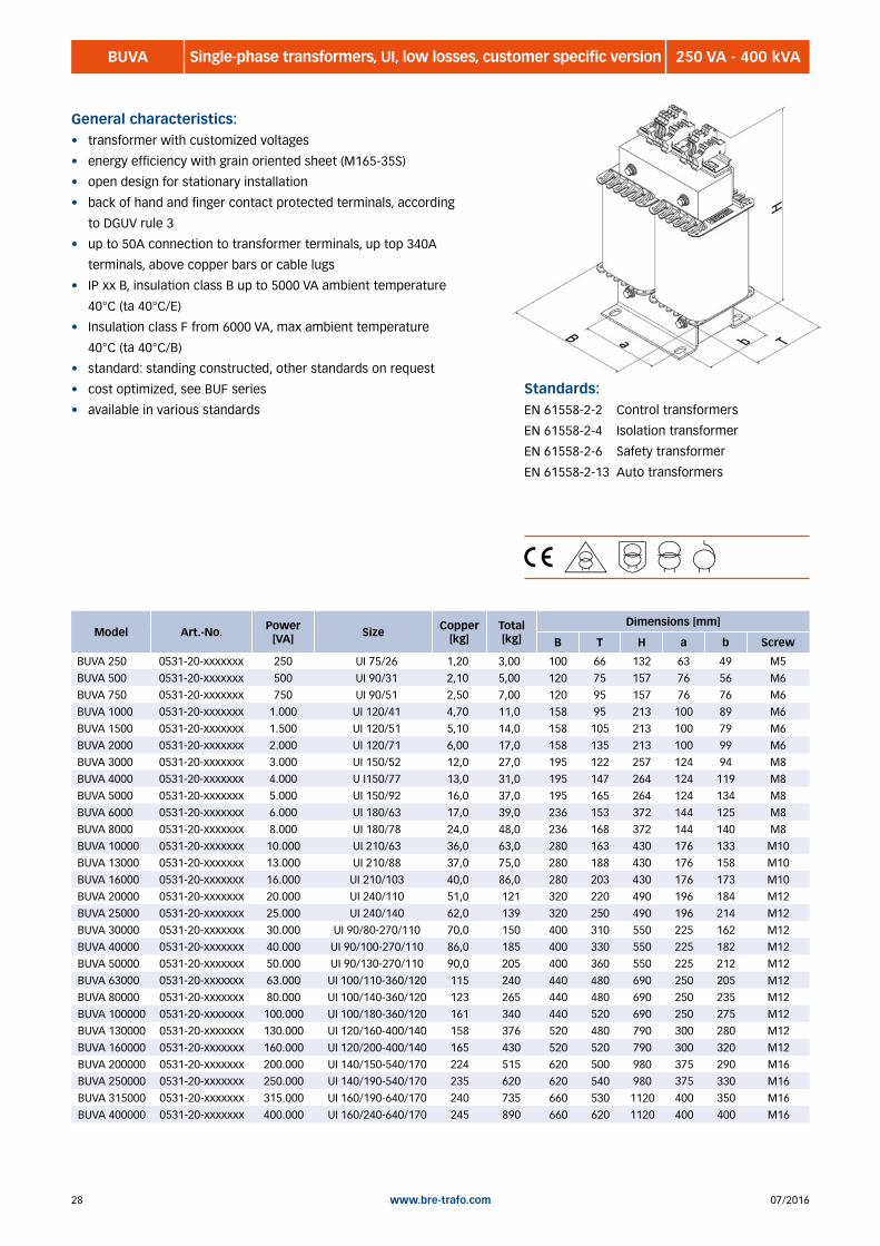
BUVA 250 VA - 400 kVASingle-phase transformers, UI, low losses, customer specific version
General characteristics:• transformer with customized voltages
• energy efficiency with grain oriented sheet (M165-35S)
• open design for stationary installation
• back of hand and finger contact protected terminals, according
to DGUV rule 3
• up to 50A connection to transformer terminals, up top 340A
terminals, above copper bars or cable lugs
• IP xx B, insulation class B up to 5000 VA ambient temperature
40°C (ta 40°C/E)
• Insulation class F from 6000 VA, max ambient temperature
40°C (ta 40°C/B)
• standard: standing constructed, other standards on request
• cost optimized, see BUF series
• available in various standards
Standards:EN 61558-2-2 Control transformers
EN 61558-2-4 Isolation transformer
EN 61558-2-6 Safety transformer
EN 61558-2-13 Auto transformers
Model Art.-No. Power [VA] Size Copper
[kg] Total [kg]
Dimensions [mm]
B T H a b Screw
BUVA 250 0531-20-xxxxxxx 250 UI 75/26 1,20 3,00 100 66 132 63 49 M5
BUVA 500 0531-20-xxxxxxx 500 UI 90/31 2,10 5,00 120 75 157 76 56 M6
BUVA 750 0531-20-xxxxxxx 750 UI 90/51 2,50 7,00 120 95 157 76 76 M6
BUVA 1000 0531-20-xxxxxxx 1.000 UI 120/41 4,70 11,0 158 95 213 100 89 M6
BUVA 1500 0531-20-xxxxxxx 1.500 UI 120/51 5,10 14,0 158 105 213 100 79 M6
BUVA 2000 0531-20-xxxxxxx 2.000 UI 120/71 6,00 17,0 158 135 213 100 99 M6
BUVA 3000 0531-20-xxxxxxx 3.000 UI 150/52 12,0 27,0 195 122 257 124 94 M8
BUVA 4000 0531-20-xxxxxxx 4.000 U I150/77 13,0 31,0 195 147 264 124 119 M8
BUVA 5000 0531-20-xxxxxxx 5.000 UI 150/92 16,0 37,0 195 165 264 124 134 M8
BUVA 6000 0531-20-xxxxxxx 6.000 UI 180/63 17,0 39,0 236 153 372 144 125 M8
BUVA 8000 0531-20-xxxxxxx 8.000 UI 180/78 24,0 48,0 236 168 372 144 140 M8
BUVA 10000 0531-20-xxxxxxx 10.000 UI 210/63 36,0 63,0 280 163 430 176 133 M10
BUVA 13000 0531-20-xxxxxxx 13.000 UI 210/88 37,0 75,0 280 188 430 176 158 M10
BUVA 16000 0531-20-xxxxxxx 16.000 UI 210/103 40,0 86,0 280 203 430 176 173 M10
BUVA 20000 0531-20-xxxxxxx 20.000 UI 240/110 51,0 121 320 220 490 196 184 M12
BUVA 25000 0531-20-xxxxxxx 25.000 UI 240/140 62,0 139 320 250 490 196 214 M12
BUVA 30000 0531-20-xxxxxxx 30.000 UI 90/80-270/110 70,0 150 400 310 550 225 162 M12
BUVA 40000 0531-20-xxxxxxx 40.000 UI 90/100-270/110 86,0 185 400 330 550 225 182 M12
BUVA 50000 0531-20-xxxxxxx 50.000 UI 90/130-270/110 90,0 205 400 360 550 225 212 M12
BUVA 63000 0531-20-xxxxxxx 63.000 UI 100/110-360/120 115 240 440 480 690 250 205 M12
BUVA 80000 0531-20-xxxxxxx 80.000 UI 100/140-360/120 123 265 440 480 690 250 235 M12
BUVA 100000 0531-20-xxxxxxx 100.000 UI 100/180-360/120 161 340 440 520 690 250 275 M12
BUVA 130000 0531-20-xxxxxxx 130.000 UI 120/160-400/140 158 376 520 480 790 300 280 M12
BUVA 160000 0531-20-xxxxxxx 160.000 UI 120/200-400/140 165 430 520 520 790 300 320 M12
BUVA 200000 0531-20-xxxxxxx 200.000 UI 140/150-540/170 224 515 620 500 980 375 290 M16
BUVA 250000 0531-20-xxxxxxx 250.000 UI 140/190-540/170 235 620 620 540 980 375 330 M16
BUVA 315000 0531-20-xxxxxxx 315.000 UI 160/190-640/170 240 735 660 530 1120 400 350 M16
BUVA 400000 0531-20-xxxxxxx 400.000 UI 160/240-640/170 245 890 660 620 1120 400 400 M16

2907/2016 www.bre-trafo.com
BUH 8 - 500 kVASingle-phase transformers, UI, cost optimized, customer specific version
Standards:EN 61558-2-2 Control transformers
EN 61558-2-4 Isolation transformer
EN 61558-2-6 Safety transformer
EN 61558-2-13 Auto transformers
Model Art.-No. Power [VA] Size Copper
[kg] Total [kg]
Dimensions [mm]
B T H a b Screw
General characteristics:• transformer with customized voltages
• cost optimized
• open design for stationary installation
• back of hand and finger contact protected terminals, according
to DGUV rule 3
• up to 50A connection to transformer terminals, up top 340A
terminals, above copper bars or cable lugs
• IP xx B, insulation class B up to 5000 VA ambient temperature
40°C (ta 40°C/F)
• Insulation class F from 6000 VA, max ambient temperature 40°C
(ta 40°C/F)
• standard: standing constructed, other standards on request
• low losses versions, see BUVA or BUVU series
• available in various standards

07/201630 www.bre-trafo.com
BELT 1 - 30 ASingle-phase fan transformers
General characteristics:• for stepwise speed control of fan motors
• voltage AC 230 V/AC 80-100-130-160-190-230 v
• welded
• housing with selector switch and protection optional available
• back of hand and finger contact protected terminals, according
to DGUV rule 3
• IP xx B, insulation class B, max ambient temperature
40°C (ta 40°C/B)
• loss optimized versions on request
Standards:EN 61558-2-13 Auto transformers
Model Art.-No. Current [A]
Copper [kg]
Total [kg]
Dimensions [mm]
B T H a b Screw
BELT 2301 0533-10-000001 1 0,19 1,00 66 78 85 50 52 M4
BELT 2302 0533-10-000002 2 0,34 1,50 85 70 96 64 47 M4
BELT 2304 0533-10-000004 4 0,57 2,90 96 90 104 84 70 M5
BELT 2307 0533-10-000007 7 1,08 4,40 120 88 121 90 70 M5
BELT 23010 0533-10-000010 10 1,30 6,00 120 108 120 90 90 M6
BELT 23013 0533-10-000013 13 1,61 7,50 135 115 131 104 96 M6
BELT 23016 0533-10-000016 16 1,91 8,70 135 125 131 104 106 M6
BELT 23020 0533-10-000020 20 2,37 10,2 150 124 145 122 101 M6
BELT 23025 0533-10-000025 25 2,80 13,4 150 150 145 122 127 M6
BELT 23030 0533-10-000030 30 3,40 15,2 174 138 157 135 106 M6

3107/2016 www.bre-trafo.com
BBIT 250 - 3.600 VABuilding sites isolation transformers
General characteristics:• Transformer in impact resistant, self extinguishing non hygroskopic
fiberglass housing IP44
• safety class 2
• supply cable 5m (protective contact or CEE plug at buyer‘s option)
• output at protective contact socket (PE not connected)
• Fuse, limited inrush current
• standard voltage: input AC 230V, output AC 230V
• max ambient temperature 40°C (ta 40°C)
• other voltages, models, sockets and plugs on request
• portable
Standards:EN 61558-2-4 Isolation transformer
EN 61558-2-23 Transformers for building sites
Model Art.-No. Power [VA]
Copper [kg]
Total [kg]
Dimensions [mm]
B T H
BBIT 250 0534-10-000250 250 0,80 7,00 166 250 219
BBIT 500 0534-10-000500 500 1,50 11,0 166 250 219
BBIT 800 0534-10-000800 800 2,50 13,0 192 276 259
BBIT 1000 0534-10-001000 1000 3,00 17,0 192 276 259
BBIT 1600 0534-10-001600 1600 3,80 22,0 340 265 280
BBIT 2000 0534-10-002000 2000 5,20 26,0 340 265 280
BBIT 2500 0534-10-002500 2500 5,90 31,0 340 265 280
BBIT 3000 0534-10-003000 3000 6,80 33,0 340 265 280BBIT 3600 0534-10-003600 3600 12,3 36,0 340 265 280
07/201632 www.bre-trafo.com
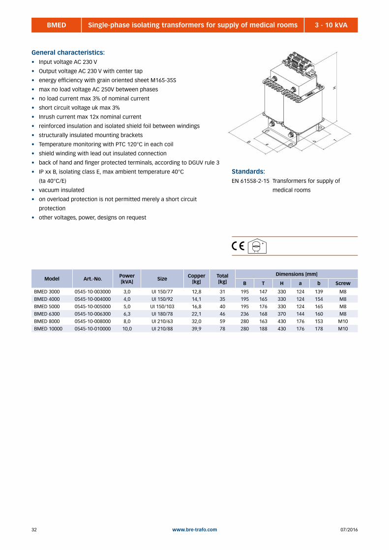
BMED 3 - 10 kVASingle-phase isolating transformers for supply of medical rooms
General characteristics:• Input voltage AC 230 V
• Output voltage AC 230 V with center tap
• energy efficiency with grain oriented sheet M165-35S
• max no load voltage AC 250V between phases
• no load current max 3% of nominal current
• short circuit voltage uk max 3%
• Inrush current max 12x nominal current
• reinforced insulation and isolated shield foil between windings
• structurally insulated mounting brackets
• Temperature monitoring with PTC 120°C in each coil
• shield winding with lead out insulated connection
• back of hand and finger protected terminals, according to DGUV rule 3
• IP xx B, isolating class E, max ambient temperature 40°C
(ta 40°C/E)
• vacuum insulated
• on overload protection is not permitted merely a short circuit
protection
• other voltages, power, designs on request
Standards:EN 61558-2-15 Transformers for supply of
medical rooms
Model Art.-No. Power [kVA] Size Copper
[kg] Total [kg]
Dimensions [mm]
B T H a b Screw
BMED 3000 0545-10-003000 3,0 UI 150/77 12,8 31 195 147 330 124 139 M8
BMED 4000 0545-10-004000 4,0 UI 150/92 14,1 35 195 165 330 124 154 M8
BMED 5000 0545-10-005000 5,0 UI 150/103 16,8 40 195 176 330 124 165 M8
BMED 6300 0545-10-006300 6,3 UI 180/78 22,1 46 236 168 370 144 160 M8
BMED 8000 0545-10-008000 8,0 UI 210/63 32,0 59 280 163 430 176 153 M10
BMED 10000 0545-10-010000 10,0 UI 210/88 39,9 78 280 188 430 176 178 M10

3307/2016 www.bre-trafo.com
BOPL 100 - 1000 VASingle-phase isolating transformer for supply of surgical lights
General characteristics:• Input voltage AC 230 V ±5% ±10%
• Output voltage AC 23/24/25/26/27/28 V
• reinforced insulation and isolated shield foil between the windings
• structurally insulated mounting brackets
• shield winding with lead out insulated connection
• back of hand and finger protected terminals, according to DGUV rule 3
• IP xx B, isolating class E, max ambient temperature 40°C
• other voltages, power, designs on request
Standards:EN 61558-2-6 Safety transformer
Model Art.-No. Power [VA]
Output current [A] Size Copper
[kg] Total [kg]
Dimensions [mm]
B T H a b Screw
BOPL 100 0546-10-000100 100 3,57 EI 84/43 0,33 1,68 85 68 93 64 57 M4
BOPL 160 0546-10-000160 160 5,70 EI 96/45 0,45 2,95 96 88 104 84 80 M5
BOPL 270 0546-10-000270 270 9,64 EI 105/60 0,63 4,70 105 104 110 84 95 M5
BOPL 400 0546-10-000400 400 14,3 EI 120/61 1,00 6,20 120 108 120 90 100 M5
BOPL 630 0546-10-000630 630 22,5 EI 135/62 1,76 7,00 135 115 131 104 106 M5
BOPL 800 0546-10-000800 800 28,6 EI 150N/66 2,43 10,1 150 124 145 122 111 M6BOPL 1000 0546-10-001000 1000 35,7 EI 150N/92 2,64 13,0 150 150 145 122 137 M6

07/201634 www.bre-trafo.com
Notes

3507/2016 www.bre-trafo.com
BDLT Three-phase auto transformers (for fan and motor regulation) .......................................................................... 40 BDUT Three-phase universal transformers ................................................................................................................... 41 BDF Three-phase transformers, cost-optimized, customer specific version .............................................................. 42 BDVA Three-phase transformers, low power losses, customer specific version .......................................................... 44 BDH Three-phase transformers, cost-optimized, customer specific version .............................................................. 46 BNLB Three-phase transformers to create a neutral formers ...................................................................................... 48 BDSW Universal three-phase transformers ................................................................................................................... 49 BDMED Three-phase isolating transformer for supply of medical rooms ........................................................................ 52
2 | THREE-PHASE TRANSFORMERS

07/201636 www.bre-trafo.com
Circuits and vector groups
Breimer Roth Transformers are characterized after the world‘s common and understandable, for the user approach, its
three-phase transformers as follows:
The first capital letter describes the primary input winding and the second lower case letter the secondary output
winding.
If there are not contrary ordering information with more accurate location assignment of upper and under voltage
formulated, the labelling type above is selected.
Capacity of the neutral conductor (neutral point):
In the star - star connection (Y y) the neutral point may only be charged with the full rated current if the neutral conductor
of the supply system is connected to the primary side of the transformer neutral point.
For three-phase autotransformers, which are made with the Star-centowinding, the same rule applies. if a fully resilient
star point may be desired , but is not available on the grid side , the double Zickzack.circuit ( ZZan0 ) must be selected.

3707/2016 www.bre-trafo.com
Circuits and vector groups
Ratio Vector group Vector diagramprimary
Vector diagramsecondary
Circuit diagramprimary
Circuit diagramsecondary
secondary neutral point
D d 00
unavailable
1V
1U 1W
2V
2U 2W
1U 1V 1W 2U 2V 2W
D d 66
unavailable
1V
1U 1W 2V
2W 2U 1U 1V 1W
2U 2V 2W
ZZa00
loadable1V
2V
2U
1U
2W1W
2U 2V 2W
Y d 55
unavailable2W
2V
2U1V
1U 1W
1UN 1V 1W
1U 1W 2U 2W
Y y 00load10 %
1V 2V 1UN 1V 1W 2UN 2V 2W
D y 55
loadable
1V
1U 1W
1U 1V 1W2U
2W
2V 2U 2V 2W N
1UN 1V 1WY y 66
load10 %
2V
2W 2U1V
1U 1W 2U 2V 2W N
Y z 55
loadable
1V
1U 1W
1UN 1V 1W2U
2W
2V 2U 2V 2W N
D z 66
loadable
1V
1U 1W
1U 1V 1W2W
2V
2U
2U 2V 2W N
1U 1W
D z 00
loadable
1V 1U 1V 1W 2U 2V 2W N2V
2U 2W
D y 1111
loadable
1V
1U 1W
1U 1V 1W2V
2W
2U
2U N2V 2W
1UN 1V 1WY d 1111
unavailable
2U 2V 2W1V
1U 1W
2W
2U
2V
1UN 1V 1WY z 1111
loadable
1V
1U 1W
2V
2W
2U
2U 2V 2WN
Y a 00load10 %
1U 1V 1W2U 2V 2W N1V
2V2U
2W1U 1W
1U
N
1V 1W
2U 2V 2W

07/201638 www.bre-trafo.com
Use of autotransformers in delta grids
The use of auto transformers in all countries with delta grids, should be examined particularly (e.g. USA,
Japan, Korea etc.). There may be problems with the specific network forms and their grounding options. In the
diagram shown below, some error cases are illustrated and described. Here, the blue graph represents the
customer‘s network and the black graphic the autotransformer.
We are happy to advise you on this, with more details.
1. Failure of a primary-side phase. The neutral point can uncontrollably reach a higher potential. This can lead to the
destruction of the consumer and the transformer.
2. Network: Center tap grounded: This is a typical network in North America. For example, here are tensions arising
from 3x 480V or 2 x 240V to the grounded center.
3. Network: Corner grounded delta: Also typical network configuration in North America and Asia. Here 3 core cables
are mostly used, whereby the green / yellow wire is simultaneously used for the outer conductor. This is by no means
to be confused with the cables used in european countries for single-phase network!
4. In many applications, the neutral of the transformer is grounded. This is partly also required in various standards and
regulations. This ground connection would have a direct contact with the „center tap grounded“ or „corner
grounded“ point and therefore a short circuit to the outer conductor!
5. Output section load, such as Line filter, main switch, inverter (DC links) are usually equipped with Y capacitors. These
cause the same error as described in point 4.
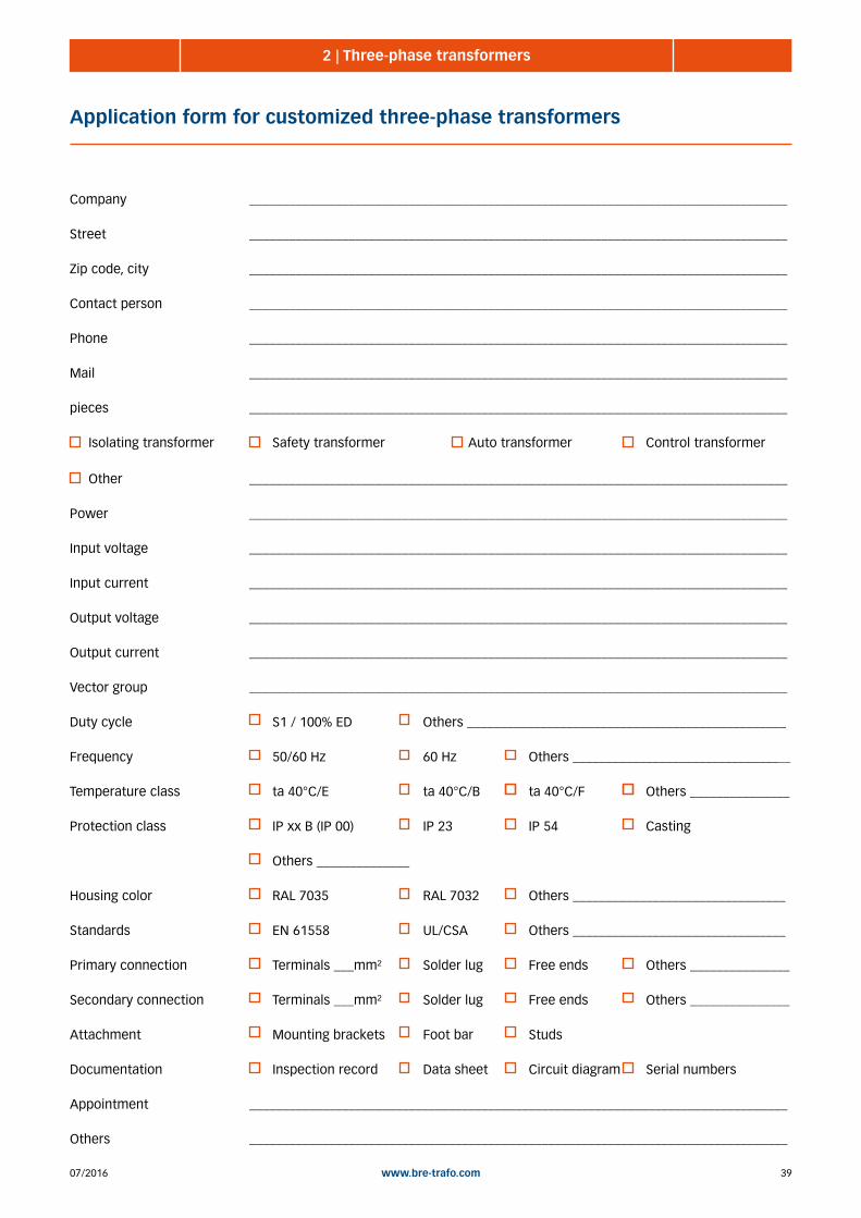
3907/2016 www.bre-trafo.com
2 | Three-phase transformers
Application form for customized three-phase transformers
Company _________________________________________________________________________________
Street _________________________________________________________________________________
Zip code, city _________________________________________________________________________________
Contact person _________________________________________________________________________________
Phone _________________________________________________________________________________
Mail _________________________________________________________________________________
pieces _________________________________________________________________________________
Isolating transformer Safety transformer Auto transformer Control transformer
Other _________________________________________________________________________________
Power _________________________________________________________________________________
Input voltage _________________________________________________________________________________
Input current _________________________________________________________________________________
Output voltage _________________________________________________________________________________
Output current _________________________________________________________________________________
Vector group _________________________________________________________________________________
Duty cycle S1 / 100% ED Others ________________________________________________
Frequency 50/60 Hz 60 Hz Others _________________________________
Temperature class ta 40°C/E ta 40°C/B ta 40°C/F Others _______________
Protection class IP xx B (IP 00) IP 23 IP 54 Casting
Others ______________
Housing color RAL 7035 RAL 7032 Others ________________________________
Standards EN 61558 UL/CSA Others ________________________________
Primary connection Terminals ___mm² Solder lug Free ends Others _______________
Secondary connection Terminals ___mm² Solder lug Free ends Others _______________
Attachment Mounting brackets Foot bar Studs
Documentation Inspection record Data sheet Circuit diagram Serial numbers
Appointment _________________________________________________________________________________
Others _________________________________________________________________________________

07/201640 www.bre-trafo.com
BDLT 1 - 30 AThree-phase fan transformers
General characteristics: • for stepwise speed control of fan motors
• voltage: AC 400 V / AV 140-180-230-280-330 V
• welded
• open design for stationary installation
• housing with selector switch and protection optionally available
• back of hand and finger contact protected terminals, according
to DGUV rule 3
• IP xx B, insulation class B, max ambient temperature
40°C (ta 40°C/B)
• scott-v-circuit
• loss optimized versions on request
• supplied in a set (2 Transformers)
• copper weights are also per set
Standards: EN 61558-2-13 Auto transformers
Model Art.-No. Current [A]
Copper [kg] Total [kg]
Dimensions [mm]
B T H a b Screw
BDLT 4001 0600-10-000001 1 0,54 1,60 78 80 89 56 54 M4
BDLT 4002 0600-10-000002 2 1,14 2,50 96 78 104 84 60 M5
BDLT 4004 0600-10-000004 4 1,62 4,40 105 104 110 84 85 M5
BDLT 4007 0600-10-000007 7 3,38 6,80 135 105 131 104 86 M6
BDLT 40010 0600-10-000010 10 4,16 8,80 135 125 131 104 106 M6
BDLT 40012 0600-10-000012 12 4,62 10,2 150 124 145 122 101 M6
BDLT 40015 0600-10-000015 15 4,84 12,9 150 150 145 122 127 M6
BDLT 40020 0600-10-000020 20 7,90 17,1 174 148 157 135 116 M6
BDLT 40025 0600-10-000025 25 9,74 21,9 174 168 157 135 136 M6
BDLT 40030 0600-10-000030 30 11,3 23,6 195 154 178 150 122 M8
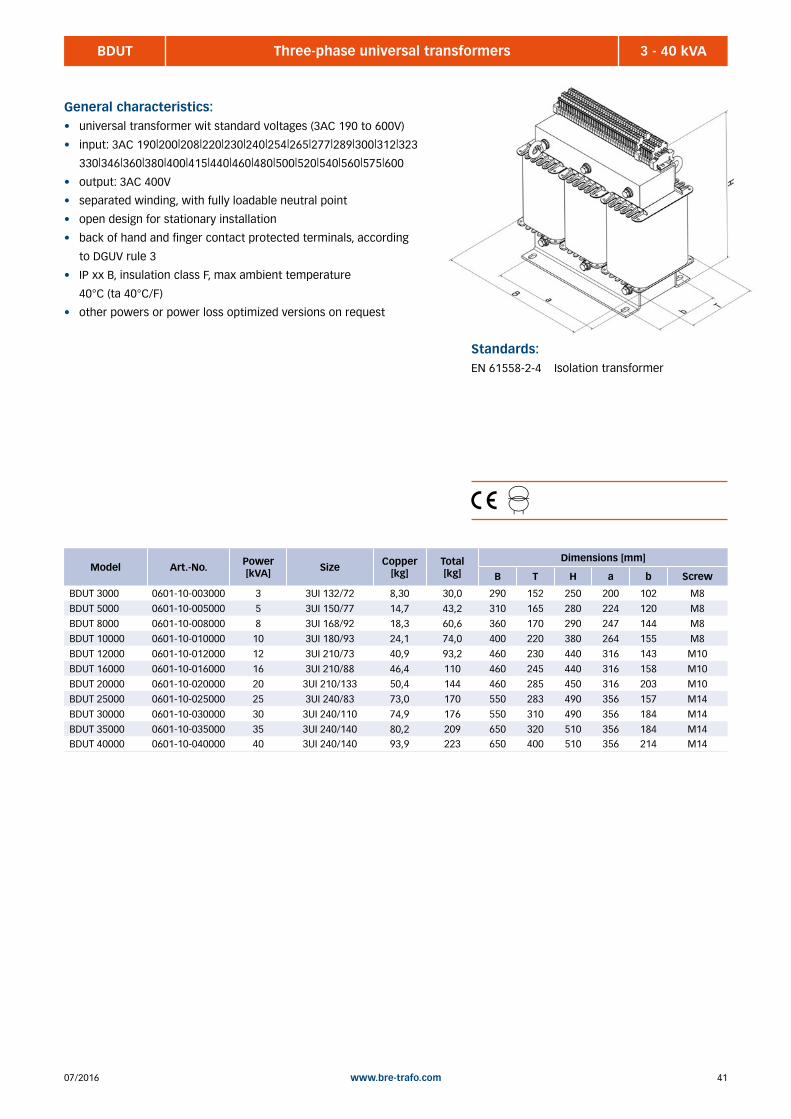
4107/2016 www.bre-trafo.com
BDUT 3 - 40 kVAThree-phase universal transformers
General characteristics:• universal transformer wit standard voltages (3AC 190 to 600V)
• input: 3AC 190|200|208|220|230|240|254|265|277|289|300|312|323
330|346|360|380|400|415|440|460|480|500|520|540|560|575|600
• output: 3AC 400V
• separated winding, with fully loadable neutral point
• open design for stationary installation
• back of hand and finger contact protected terminals, according
to DGUV rule 3
• IP xx B, insulation class F, max ambient temperature
40°C (ta 40°C/F)
• other powers or power loss optimized versions on request
Standards:EN 61558-2-4 Isolation transformer
Model Art.-No. Power [kVA] Size Copper
[kg] Total [kg]
Dimensions [mm]
B T H a b Screw
BDUT 3000 0601-10-003000 3 3UI 132/72 8,30 30,0 290 152 250 200 102 M8
BDUT 5000 0601-10-005000 5 3UI 150/77 14,7 43,2 310 165 280 224 120 M8
BDUT 8000 0601-10-008000 8 3UI 168/92 18,3 60,6 360 170 290 247 144 M8
BDUT 10000 0601-10-010000 10 3UI 180/93 24,1 74,0 400 220 380 264 155 M8
BDUT 12000 0601-10-012000 12 3UI 210/73 40,9 93,2 460 230 440 316 143 M10
BDUT 16000 0601-10-016000 16 3UI 210/88 46,4 110 460 245 440 316 158 M10
BDUT 20000 0601-10-020000 20 3UI 210/133 50,4 144 460 285 450 316 203 M10
BDUT 25000 0601-10-025000 25 3UI 240/83 73,0 170 550 283 490 356 157 M14
BDUT 30000 0601-10-030000 30 3UI 240/110 74,9 176 550 310 490 356 184 M14
BDUT 35000 0601-10-035000 35 3UI 240/140 80,2 209 650 320 510 356 184 M14BDUT 40000 0601-10-040000 40 3UI 240/140 93,9 223 650 400 510 356 214 M14

07/201642 www.bre-trafo.com
BDF 50 VA - 130 kVAThree-phase transformers, cost optimized, customer specific version
General characteristics:• transformer with customized voltages up to 1000V, larger voltage on
request
• cost optimized model with sheet (M330-50A)
• reduced sizes
• open design for stationary installation
• back of hand finger protected terminals, according to DGUV rule 3
(IPxxB)
• electric currents above 340A, needs electric connections on cable lugs
or copper plates (IP00)
• insulation class B, max ambient temperature 40°C (ta 40°C/B)
up to 3500 VA
• insulation class F, max ambient temperature 40°C (ta 40°C/F)
from 4000 VA
• available in various standards
• standard: standing construction with mounting brakets
• in sizes up to 40 kVA change the measurements of high and depth
from currents higher than 50A
• loss optimized models, see BDVA
Standards:EN 61558-2-2 Control transformers
EN 61558-2-4 Isolation transformers
EN 61558-2-6 Safety transformers
EN 61558-2-13 Auto transformers
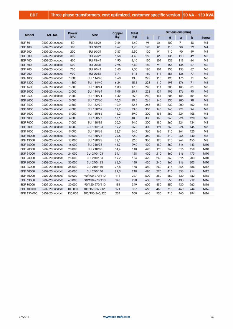
4307/2016 www.bre-trafo.com
BDF 50 VA - 130 kVAThree-phase transformers, cost optimized, customer specific version
Model Art.-No. Power [VA] Size Copper
[kg] Total [kg]
Dimensions [mm]
B T H a b Screw
BDF 50 0602-20-xxxxxx 50 3UI 48/26 0,44 1,40 96 86 100 71 48 M4
BDF 100 0602-20-xxxxxx 100 3UI 60/21 0,67 1,70 120 81 110 90 39 M4
BDF 200 0602-20-xxxxxx 200 3UI 60/31 0,87 2,50 120 91 110 90 49 M4
BDF 300 0602-20-xxxxxx 300 3UI 75/26 1,58 4,40 150 86 135 113 49 M5
BDF 400 0602-20-xxxxxx 400 3UI 75/41 1,90 6,10 150 101 135 113 64 M5
BDF 500 0602-20-xxxxxx 500 3UI 90/31 2,96 7,40 180 91 155 136 57 M6
BDF 700 0602-20-xxxxxx 700 3UI 90/41 3,40 9,30 180 101 155 136 67 M6
BDF 900 0602-20-xxxxxx 900 3UI 90/51 3,71 11,1 180 111 155 136 77 M6
BDF 1000 0602-20-xxxxxx 1.000 3UI 114/40 5,60 13,5 228 110 195 176 71 M6
BDF 1300 0602-20-xxxxxx 1.300 3UI 114/40 6,24 15,1 228 110 195 176 71 M6
BDF 1600 0602-20-xxxxxx 1.600 3UI 120/41 6,83 17,5 240 111 205 185 81 M8
BDF 2000 0602-20-xxxxxx 2.000 3UI 114/64 7,09 20,9 228 134 195 176 95 M6
BDF 2500 0602-20-xxxxxx 2.500 3UI 120/71 8,32 25,3 240 141 205 185 101 M8
BDF 3000 0602-20-xxxxxx 3.000 3UI 132/60 10,3 29,5 265 140 230 200 90 M8
BDF 3500 0602-20-xxxxxx 3.500 3UI 132/72 10,9 32,5 265 152 230 200 102 M8
BDF 4000 0602-20-xxxxxx 4.000 3UI 150/52 12,2 33,0 300 140 260 224 94 M8
BDF 5000 0602-20-xxxxxx 5.000 3UI 150/65 15,2 39,0 300 153 260 224 108 M8
BDF 6000 0602-20-xxxxxx 6.000 3UI 150/77 18,1 48,5 300 165 260 224 120 M8
BDF 7000 0602-20-xxxxxx 7.000 3UI 150/92 20,0 54,0 300 180 260 224 134 M8
BDF 8000 0602-20-xxxxxx 8.000 3UI 150/103 19,2 56,0 300 191 260 224 145 M8
BDF 9000 0602-20-xxxxxx 9.000 3UI 180/63 28,7 64,0 360 165 310 264 125 M8
BDF 10000 0602-20-xxxxxx 10.000 3UI 180/78 29,6 72,0 360 180 310 264 140 M8
BDF 13000 0602-20-xxxxxx 13.000 3UI 180/93 32,1 82,0 360 195 310 264 155 M8
BDF 16000 0602-20-xxxxxx 16.000 3UI 210/73 46,7 99,0 420 180 360 316 143 M10
BDF 20000 0602-20-xxxxxx 20.000 3UI 210/88 54,4 118 420 195 360 316 158 M10
BDF 24000 0602-20-xxxxxx 24.000 3UI 210/103 54,1 128 420 210 360 316 173 M10
BDF 28000 0602-20-xxxxxx 28.000 3UI 210/133 59,2 154 420 240 360 316 203 M10
BDF 30000 0602-20-xxxxxx 30.000 3UI 210/133 65,0 160 420 240 360 316 203 M10
BDF 36000 0602-20-xxxxxx 36.000 3UI 240/110 77,8 178 480 240 415 356 184 M12
BDF 40000 0602-20-xxxxxx 40.000 3UI 240/140 89,3 218 480 270 415 356 214 M12
BDF 50000 0602-20-xxxxxx 50.000 90/100-270/110 115 227 600 350 550 430 182 M16
BDF 63000 0602-20-xxxxxx 63.000 90/130-270/110 140 280 600 395 550 430 212 M16
BDF 80000 0602-20-xxxxxx 80.000 90/180-270/110 155 349 600 450 550 430 262 M16
BDF 100.000 0602-20-xxxxxx 100.000 100/150-360/120 171 387 660 465 710 460 244 M16BDF 130.000 0602-20-xxxxxx 130.000 100/190-360/120 234 500 660 550 710 460 284 M16

07/201644 www.bre-trafo.com
BDVA 50 VA - 630 kVAThree-phase transformers, low losses, customer specific version
General characteristics:• transformer with customized voltages up to 1000V, higher voltage on
request
• loss optimized with grain oriented sheet M165-35S
• open design for stationary installation
• back of hand finger protected terminals, according to DGUV rule 3
• currents above 340A, connections on cable lugs or copper plates (IP00)
• insulation class B, max ambient temperature 40°C (ta 40°C/B) up
to 3500 VA
• insulation class F, max ambient temperature 40°C (ta 40°C/F)
from 4000 VA
• available in various standards
• standard: standing construction with mounting brakets
• in sizes up to 40kVA change the measurements of high and depth from
currents higher than 50A
• cost optimized model, look at BDF or BDH
Standards:EN 61558-2-2 Control transformers
EN 61558-2-4 Isolation transformers
EN 61558-2-6 Safety transformers
EN 61558-2-13 Auto transformers

4507/2016 www.bre-trafo.com
BDVA 50 VA - 630 kVAThree-phase transformers, low losses, customer specific version
Model Art.-No. Power [VA] Size Copper
[kg] Total [kg]
Dimensions [mm]
B T H a b Screw
BDVA 50 0603-20-xxxxxx 50 3UI 48/26 0,44 1,40 96 86 100 71 48 M4
BDVA 100 0603-20-xxxxxx 100 3UI 60/21 0,67 1,70 120 81 110 90 39 M4
BDVA 200 0603-20-xxxxxx 200 3UI 60/31 0,87 2,50 120 91 110 90 49 M4
BDVA 300 0603-20-xxxxxx 300 3UI 75/26 1,58 4,40 150 86 135 113 49 M5
BDVA 400 0603-20-xxxxxx 400 3UI 75/41 1,90 6,10 150 101 135 113 64 M5
BDVA 500 0603-20-xxxxxx 500 3UI 90/31 2,96 7,40 180 91 155 136 57 M6
BDVA 700 0603-20-xxxxxx 700 3UI 90/41 3,40 9,30 180 101 155 136 67 M6
BDVA 900 0603-20-xxxxxx 900 3UI 90/51 3,71 11,1 180 111 155 136 77 M6
BDVA 1000 0603-20-xxxxxx 1.000 3UI 114/40 3,37 12,5 228 110 195 176 71 M6
BDVA 1300 0603-20-xxxxxx 1.300 3UI 114/40 6,24 15,1 228 110 195 176 71 M6
BDVA 1600 0603-20-xxxxxx 1.600 3UI 120/41 6,83 17,5 240 111 205 185 81 M8
BDVA 2000 0603-20-xxxxxx 2.000 3UI 114/64 7,09 20,9 228 134 195 176 95 M6
BDVA 2500 0603-20-xxxxxx 2.500 3UI 120/71 8,32 25,3 240 141 205 185 101 M8
BDVA 3000 0603-20-xxxxxx 3.000 3UI 132/60 10,3 29,5 265 140 230 200 90 M8
BDVA 3500 0603-20-xxxxxx 3.500 3UI 132/72 10,9 32,5 265 152 230 200 102 M8
BDVA 4000 0603-20-xxxxxx 4.000 3UI 150/52 12,2 33,0 300 140 260 224 94 M8
BDVA 5000 0603-20-xxxxxx 5.000 3UI 150/65 15,2 39,0 300 153 260 224 108 M8
BDVA 6000 0603-20-xxxxxx 6.000 3UI 150/77 18,1 48,5 300 165 260 224 120 M8
BDVA 7000 0603-20-xxxxxx 7.000 3UI 150/92 20,0 54,0 300 180 260 224 134 M8
BDVA 8000 0603-20-xxxxxx 8.000 3UI 150/103 19,2 56,0 300 191 260 224 145 M8
BDVA 9000 0603-20-xxxxxx 9.000 3UI 180/63 28,7 64,0 360 165 310 264 125 M8
BDVA 10000 0603-20-xxxxxx 10.000 3UI 180/78 29,6 72,0 360 180 310 264 140 M8
BDVA 13000 0603-20-xxxxxx 13.000 3UI 180/93 32,1 82,0 360 195 310 264 155 M8
BDVA 16000 0603-20-xxxxxx 16.000 3UI 210/73 46,7 99,0 420 180 360 316 143 M10
BDVA 20000 0603-20-xxxxxx 20.000 3UI 210/88 54,4 118 420 195 360 316 158 M10
BDVA 24000 0603-20-xxxxxx 24.000 3UI 210/103 54,1 128 420 210 360 316 173 M10
BDVA 28000 0603-20-xxxxxx 28.000 3UI 210/133 59,2 154 420 240 360 316 203 M10
BDVA 32000 0603-20-xxxxxx 32.000 3UI 210/133 60,1 155 420 240 360 316 203 M10
BDVA 36000 0603-20-xxxxxx 36.000 3UI 240/110 77,8 178 480 240 415 356 184 M12
BDVA 40000 0603-20-xxxxxx 40.000 3UI 240/140 89,3 218 480 270 415 356 214 M12
BDVA 50000 0603-20-xxxxxx 50.000 90/100/270/110 92,0 220 600 380 600 430 182 M16
BDVA 63000 0603-20-xxxxxx 63.000 90/110/270/110 127 244 600 390 600 430 192 M16
BDVA 80000 0603-20-xxxxxx 80.000 90/130/270/110 138 277 600 410 600 430 212 M16
BDVA 100.000 0603-20-xxxxxx 100.000 90/170-270/110 154 334 600 510 600 430 252 M16
BDVA 130.000 0603-20-xxxxxx 130.000 100/160-360/120 192 409 660 500 710 460 254 M16
BDVA 160.000 0603-20-xxxxxx 160.000 100/190-360/120 242 494 660 530 710 460 284 M16
BDVA 200.000 0603-20-xxxxxx 200.000 120/150-400/140 280 572 780 505 790 560 266 M16
BDVA 250.000 0603-20-xxxxxx 250.000 120/190-400/140 363 708 780 545 790 560 306 M16
BDVA 315.000 0603-20-xxxxxx 315.000 140/160-540/170 * * * * * * * *
BDVA 400.000 0603-20-xxxxxx 400.000 140/200-540/170 * * * * * * * *
BDVA 500.000 0603-20-xxxxxx 500.000 160/190-640/170 * * * * * * * *
BDVA 630.000 0603-20-xxxxxx 630.000 160/280-640/170 * * * * * * * *
* on request

07/201646 www.bre-trafo.com
BDH 10 - 630 kVAThree-phase transformers, cost optimized, customer specific version
Standards:EN 61558-2-2 Control transformers
EN 61558-2-4 Isolation transformer
EN 61558-2-6 Safety transformer
EN 61558-2-13 Auto transformers
General characteristics:• transformer with customized voltages up to 1000V, larger voltage on
request
• cost optimized model with sheet (M330-50A)
• reduced sizes
• open design for stationary installation
• back of hand finger protected terminals, according to DGUV rule 3
(IPxxB)
• electric currents above 340A, needs electric connections on cable
lugs or copper plates (IP00)
• insulation class B, max ambient temperature 40°C (ta 40°C/B)
up to 3500 VA
• insulation class F, max ambient temperature 40°C (ta 40°C/F)
from 4000 VA
• available in various standards
• standard: standing construction with mounting brakets
• in sizes up to 40 kVA change the measurements of high and depth
from currents higher than 50A
• loss optimized models, see BDVA

4707/2016 www.bre-trafo.com
BDH 10 - 630 kVAThree-phase transformers, cost optimized, customer specific version
Model Art.-No. Power [VA] Size Copper
[kg] Total [kg]
Dimensions [mm]
B T H a b Screw
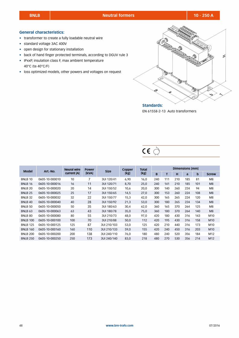
07/201648 www.bre-trafo.com
BNLB 10 - 250 ANeutral formers
General characteristics:• transformer to create a fully loadable neutral wire
• standard voltage 3AC 400V
• open design for stationary installation
• back of hand finger protected terminals, according to DGUV rule 3
• IPxxP, insulation class F, max ambient temperature
40°C (ta 40°C/F)
• loss optimized models, other powers and voltages on request
Standards:EN 61558-2-13 Auto transformers
Model Art.-No. Neural wire current [A]
Power [kVA] Size Copper
[kg] Total [kg]
Dimensions [mm]
B T H a b Screw
BNLB 10 0605-10-000010 10 7 3UI 120/41 6,90 16,0 240 111 210 185 81 M8
BNLB 16 0605-10-000016 16 11 3UI 120/71 8,70 25,0 240 141 210 185 101 M8
BNLB 20 0605-10-000020 20 14 3UI 150/52 10,6 20,0 300 140 260 224 94 M8
BNLB 25 0605-10-000025 25 17 3UI 150/65 14,5 27,0 300 153 260 224 108 M8
BNLB 32 0605-10-000032 32 22 3UI 150/77 15,3 42,0 300 165 265 224 120 M8
BNLB 40 0605-10-000040 40 28 3UI 150/92 21,3 53,0 300 180 265 224 134 M8
BNLB 50 0605-10-000050 50 35 3UI 180/63 30,4 62,0 360 165 370 264 125 M8
BNLB 63 0605-10-000063 63 43 3UI 180/78 35,0 75,0 360 180 370 264 140 M8
BNLB 80 0605-10-000080 80 55 3UI 210/73 48,0 97,0 420 180 430 316 143 M10
BNLB 100 0605-10-000100 100 70 3UI 210/88 50,0 112 420 195 430 316 158 M10
BNLB 125 0605-10-000125 125 87 3UI 210/103 53,0 125 420 210 440 316 173 M10
BNLB 160 0605-10-000160 160 110 3UI 210/133 59,0 155 420 240 450 316 203 M10
BNLB 200 0605-10-000200 200 138 3UI 240/110 76,0 180 480 240 520 356 184 M12
BNLB 250 0605-10-000250 250 173 3UI 240/140 83,0 218 480 270 530 356 214 M12

4907/2016 www.bre-trafo.com
BDSW 2 - 250 kVAThree-phase Auto transformers for worldwide use
General characteristics:• auto transformers with standard voltages for worldwide use
• various input voltages (according to the list)
• output voltage 3AC 400V
• open design for stationary installation
• back of hand finger protected terminals, according to DGUV rule 3
• IPxxB, insulation class F, max ambient temperature
40°C (ta 40°C/F)
Please check in advance whether an autotransformer is applicable!
See also the information at page 38.
Standards:EN 61558-2-13 Auto transformers

07/201650 www.bre-trafo.com
BDSW 2 - 250 kVAThree-phase auto transformers for worldwide use
Input voltage: 3AC 240/346 V
Model Art.-No. Power [kVA]
Copper [kg]
Total [kg]
Dimensions [mm]
B T H a b Screw
BDSW 2-240 0612-10-000002 2 2,80 8,70 180 101 155 136 67 M6
BDSW 3,5-240 0612-10-00003,5 3,5 6,80 15,5 228 110 195 176 71 M6
BDSW 10-240 0612-10-000010 10 7,20 31,6 300 153 260 224 108 M8
BDSW 15-240 0612-10-000015 15 17,3 46,4 300 165 260 224 120 M8
BDSW 25-240 0612-10-000025 25 26,0 68,0 360 180 310 264 140 M8
BDSW 45-240 0612-10-000045 45 44,2 108 420 195 440 316 158 M10
BDSW 70-240 0612-10-000070 70 59,0 154 420 240 440 316 203 M10
BDSW 110-240 0612-10-000110 110 86,5 216 480 270 500 356 214 M12
BDSW 160-240 0612-10-000160 160 116 280 600 395 550 430 212 M16
BDSW 250-240 0612-10-000250 250 184 387 660 465 710 460 244 M16
Input voltage: 3AC 380/415V
Model Art.-No. Power [kVA]
Copper [kg]
Total [kg]
Dimensions [mm]
B T H a b Screw
BDSW 2-380 0613-10-000002 2 0,80 1,80 120 81 110 90 39 M4
BDSW 3,5-380 0613-10-00003,5 3,5 0,70 2,30 120 91 110 90 49 M4
BDSW 10-380 0613-10-000010 10 2,50 8,40 180 101 155 136 67 M6
BDSW 15-380 0613-10-000015 15 3,40 10,5 180 111 155 136 77 M6
BDSW 25-380 0613-10-000025 25 6,30 20,0 228 134 195 176 95 M6
BDSW 45-380 0613-10-000045 45 11,4 35,5 300 153 330 224 108 M8
BDSW 70-380 0613-10-000070 70 12,2 39,7 300 165 330 224 120 M8
BDSW 110-380 0613-10-000110 110 19,6 54,3 336 170 380 248 127 M8
BDSW 160-380 0613-10-000160 160 31,5 80,0 420 180 450 316 143 M10
BDSW 250-380 0613-10-000250 250 37,7 131 420 240 450 316 203 M10
Model Art.-No. Power [kVA]
Copper [kg]
Total [kg]
Dimensions [mm]
B T H a b Screw
BDSW 2-220 0611-10-000002 2 3,50 10,9 180 111 155 136 77 M6
BDSW 3,5-220 0611-10-00003,5 3,5 6,30 20,2 228 134 195 176 95 M6
BDSW 10-220 0611-10-000010 10 8,80 37,3 300 165 260 224 120 M8
BDSW 15-220 0611-10-000015 15 14,50 48,8 300 180 260 224 134 M8
BDSW 25-220 0611-10-000025 25 25,90 75,0 360 195 380 264 155 M8
BDSW 45-220 0611-10-000045 45 45,90 119 420 210 430 316 173 M10
BDSW 70-220 0611-10-000070 70 69,0 171 480 240 500 356 184 M12
BDSW 110-220 0611-10-000110 110 96,0 227 600 350 550 430 182 M16
BDSW 160-220 0611-10-000160 160 129,0 349 600 450 550 430 262 M16
BDSW 250-220 0611-10-000250 250 195,0 500 660 550 710 460 284 M16
Input voltage: 3AC 220/230 V
Input voltage: 3AC 200/208 V
Model Art.-No. Power [kVA]
Copper [kg]
Total [kg]
Dimensions [mm]
B T H a b Screw
BDSW 2-200 0610-10-000002 2 3,40 10,2 180 111 155 136 77 M6
BDSW 3,5-200 0610-10-00003,5 3,5 5,90 14,8 228 110 195 176 71 M6
BDSW 10-200 0610-10-000010 10 9,80 38,4 300 165 260 224 120 M8
BDSW 15-200 0610-10-000015 15 18,5 53,2 336 150 290 248 127 M8
BDSW 25-200 0610-10-000025 25 31,0 84,0 420 180 360 316 143 M10
BDSW 45-200 0610-10-000045 45 43,4 150 420 240 430 316 203 M10
BDSW 70-200 0610-10-000070 70 83,4 181 480 240 490 356 184 M12
BDSW 110-200 0610-10-000110 110 116 280 600 395 550 430 212 M16
BDSW 160-200 0610-10-000160 160 129 349 600 450 550 430 262 M16
BDSW 250-200 0610-10-000250 250 195 500 660 550 710 460 284 M16

5107/2016 www.bre-trafo.com
BDSW 2 - 250 kVAThree-phase auto transformers for worldwide use
Input voltage: 3AC 575/600V
Model Art.-No. Power [kVA]
Copper [kg]
Total [kg]
Dimensions [mm]
B T H a b Screw
BDSW 2-575 0616-10-000002 2 2,80 7,20 180 91 155 136 57 M6
BDSW 3,5-575 0616-10-00003,5 3,5 4,50 13,4 228 110 195 176 71 M6
BDSW 10-575 0616-10-000010 10 6,20 27,2 265 152 230 200 102 M8
BDSW 15-575 0616-10-000015 15 10,8 34,5 300 153 260 224 108 M8
BDSW 25-575 0616-10-000025 25 19,5 54,5 336 150 290 248 127 M8
BDSW 45-575 0616-10-000045 45 38,9 87,0 180 360 440 316 143 M10
BDSW 70-575 0616-10-000070 70 44,0 139 420 240 450 316 203 M10
BDSW 110-575 0616-10-000110 110 76,7 206 480 270 500 356 214 M12
BDSW 160-575 0616-10-000160 160 116 280 600 395 550 430 212 M16
BDSW 250-575 0616-10-000250 250 174 349 600 450 550 430 262 M16
Input voltage: 3AC 690V
Model Art.-No. Power [kVA]
Copper [kg]
Total [kg]
Dimensions [mm]
B T H a b Screw
BDSW 2-690 0617-10-000002 2 2,90 8,80 180 101 155 136 67 M6
BDSW 3,5-690 0617-10-00003,5 3,5 5,50 14,4 228 110 195 176 71 M6
BDSW 10-690 0617-10-000010 10 9,50 33,8 300 153 260 224 108 M8
BDSW 15-690 0617-10-000015 15 15,0 49,6 300 180 260 224 134 M8
BDSW 25-690 0617-10-000025 25 26,0 68,0 360 180 310 264 140 M8
BDSW 45-690 0617-10-000045 45 49,1 113 420 195 440 316 158 M10
BDSW 70-690 0617-10-000070 70 61,0 156 420 240 460 316 203 M10
BDSW 110-690 0617-10-000110 110 88,8 218 480 270 500 356 214 M12
BDSW 160-690 0617-10-000160 160 129 349 600 450 550 430 262 M16
BDSW 250-690 0617-10-000250 250 228 387 660 465 710 460 244 M16
Input voltage: 3AC 440/460V
Model Art.-No. Power [kVA]
Copper [kg]
Total [kg]
Dimensions [mm]
B T H a b Screw
BDSW 2-440 0614-10-000002 2 1,10 3,90 150 86 135 113 49 M5
BDSW 3,5-440 0614-10-00003,5 3,5 1,90 6,10 150 101 135 113 64 M5
BDSW 10-440 0614-10-000010 10 4,80 13,3 228 110 195 176 71 M6
BDSW 15-440 0614-10-000015 15 6,20 19,9 228 134 195 176 95 M6
BDSW 25-440 0614-10-000025 25 7,00 28,0 265 152 230 200 102 M8
BDSW 45-440 0614-10-000045 45 12,2 40,7 300 165 340 224 120 M8
BDSW 70-440 0614-10-000070 70 20,5 62,0 360 180 390 264 140 M8
BDSW 110-440 0614-10-000110 110 35,3 126 420 240 440 316 203 M10
BDSW 160-440 0614-10-000160 160 47,1 121 420 210 440 316 173 M10
BDSW 250-440 0614-10-000250 250 74,4 176 480 240 500 356 184 M12
Input voltage: 3AC 480/500V
Model Art.-No. Power [kVA]
Copper [kg]
Total [kg]
Dimensions [mm]
B T H a b Screw
BDSW 2-480 0615-10-000002 2 1,60 5,80 150 101 135 113 64 M5
BDSW 3,5-480 0615-10-00003,5 3,5 2,30 8,20 180 101 155 136 67 M6
BDSW 10-480 0615-10-000010 10 5,70 19,4 228 134 195 176 95 M6
BDSW 15-480 0615-10-000015 15 8,10 26,0 240 145 205 185 105 M8
BDSW 25-480 0615-10-000025 25 11,0 35,4 300 153 260 224 108 M8
BDSW 45-480 0615-10-000045 45 21,9 63,0 360 180 380 264 140 M8
BDSW 70-480 0615-10-000070 70 34,0 83,0 420 180 450 316 143 M10
BDSW 110-480 0615-10-000110 110 46,1 119 420 210 450 316 173 M10
BDSW 160-480 0615-10-000160 160 80,0 182 480 240 500 356 184 M12
BDSW 250-480 0615-10-000250 250 127 227 600 350 550 430 182 M16
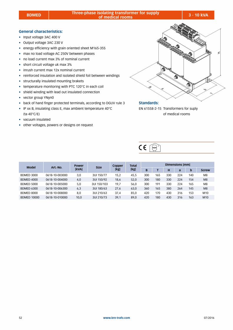
07/201652 www.bre-trafo.com
BDMED 3 - 10 kVAThree-phase isolating transformer for supply of medical rooms
General characteristics:• Input voltage 3AC 400 V
• Output voltage 3AC 230 V
• energy efficiency with grain oriented sheet M165-35S
• max no load voltage AC 250V between phases
• no load current max 3% of nominal current
• short circuit voltage uk max 3%
• inrush current max 12x nominal current
• reinforced insulation and isolated shield foil between windings
• structurally insulated mounting brakets
• temperature monitoring with PTC 120°C in each coil
• shield winding with lead out insulated connection
• vector group YNyn0
• back of hand finger protected terminals, according to DGUV rule 3
• IP xx B, insulating class E, max ambient temperature 40°C
(ta 40°C/E)
• vacuum insulated
• other voltages, powers or designs on request
Model Art.-No. Power [kVA] Size Copper
[kg] Total [kg]
Dimensions [mm]
B T H a b Screw
BDMED 3000 0618-10-003000 3,0 3UI 150/77 15,2 45,5 300 165 330 224 140 M8
BDMED 4000 0618-10-004000 4,0 3UI 150/92 18,6 52,0 300 180 330 224 154 M8
BDMED 5000 0618-10-005000 5,0 3UI 150/103 19,7 56,0 300 191 330 224 165 M8
BDMED 6300 0618-10-006300 6,3 3UI 180/63 27,6 63,0 360 165 380 264 145 M8
BDMED 8000 0618-10-008000 8,0 3UI 210/63 37,4 85,0 420 170 430 316 153 M10
BDMED 10000 0618-10-010000 10,0 3UI 210/73 39,1 89,0 420 180 430 316 163 M10
Standards:EN 61558-2-15 Transformers for suply
of medical rooms

5307/2016 www.bre-trafo.com
BEND 4 Single-phase line chokes 4% ............................................................................................................................... 56 BEND 6 Single-phase line chokes 6% ............................................................................................................................... 58 BENDD 4 Single-phase line dual choke 4% ......................................................................................................................... 60 BENDD 6 Single-phase line dual choke 6% ......................................................................................................................... 62 BEFD 5,5 Single-phase filter choke 5,5% (214 Hz) .............................................................................................................. 64 BDFD 7 Three-phase filter chokes 7% (189Hz) ................................................................................................................. 65 BDFD 14 Three-phase filter chokes 14% (134Hz) ............................................................................................................... 66 BDND 4 Three-phase line chokes 4% ............................................................................................................................... 67 BDND 6 Three-phase line chokes 6% ............................................................................................................................... 68
3 | CHOKES AND FILTERS

07/201654 www.bre-trafo.com
Notes
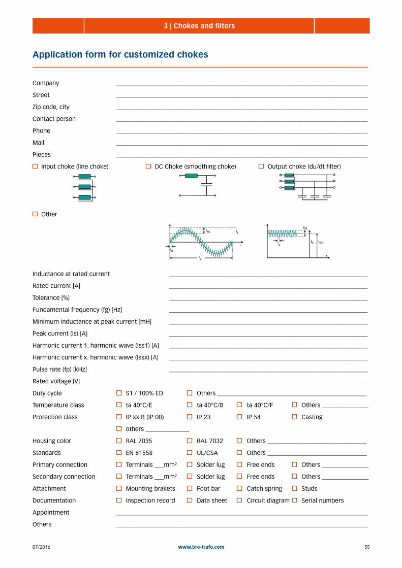
5507/2016 www.bre-trafo.com
3 | Chokes and filters
Application form for customized chokes
Company _________________________________________________________________________________
Street _________________________________________________________________________________
Zip code, city _________________________________________________________________________________
Contact person _________________________________________________________________________________
Phone _________________________________________________________________________________
Mail _________________________________________________________________________________
Pieces _________________________________________________________________________________
Input choke (line choke) DC Choke (smoothing choke) Output choke (du/dt filter)
Other _________________________________________________________________________________
Inductance at rated current ________________________________________________________________
Rated current [A] ________________________________________________________________
Tolerance [%] ________________________________________________________________
Fundamental frequency (fg) [Hz] ________________________________________________________________
Minimum inductance at peak current [mH] ________________________________________________________________
Peak current (Is) [A] ________________________________________________________________
Harmonic current 1. harmonic wave (Iss1) [A] ________________________________________________________________
Harmonic current x. harmonic wave (Issx) [A] ________________________________________________________________
Pulse rate (fp) [kHz] ________________________________________________________________
Rated voltage [V] ________________________________________________________________
Duty cycle S1 / 100% ED Others ________________________________________________
Temperature class ta 40°C/E ta 40°C/B ta 40°C/F Others _______________
Protection class IP xx B (IP 00) IP 23 IP 54 Casting
others ______________
Housing color RAL 7035 RAL 7032 Others ________________________________
Standards EN 61558 UL/CSA Others ________________________________
Primary connection Terminals ___mm² Solder lug Free ends Others _______________
Secondary connection Terminals ___mm² Solder lug Free ends Others _______________
Attachment Mounting brakets Foot bar Catch spring Studs
Documentation Inspection record Data sheet Circuit diagram Serial numbers
Appointment _________________________________________________________________________________
Others _________________________________________________________________________________

07/201656 www.bre-trafo.com
BEND 4 2 - 32 ASingle-phase line chokes 4%
General characteristics:• single-phase line choke with 4% uk
• for current limiting or rejection of the circuit feedback
• nominal voltage according to model: AC 115V, 230V (277V9, 400V (480V)
• nominal frequency 50Hz, 60Hz with other voltages possible
• open design for stationary installation
• back of hand finger protected terminals, according to DGUV rule 3
• IPxxB, insulation class B, max ambient temperature
40°C (ta 40°C/B)
Standards:EN 61558-2-20 Chokes

5707/2016 www.bre-trafo.com
BEND 4 2 - 32 ASingle-phase line chokes 4%
Model Art.-No. Current [A]
Inductance [mH] Size Copper
[kg] Total [kg]
Dimensions [mm]
B T H a b Screw
BEND4-4-115 0700-10-000004 4 3,66 EI 48/16 0,05 0,30 46 42 52 38 31 M3
BEND4-6-115 0700-10-000006 6 2,44 EI 54/18 0,05 0,35 55 76 60 44 34 M3
BEND4-8-115 0700-10-000008 8 1,83 EI 54/18 0,08 0,36 55 76 60 44 34 M3
BEND4-10-115 0700-10-000010 10 1,46 EI 60/21 0,11 0,52 60 65 76 44 36 M3
BEND4-13-115 0700-10-000013 13 1,12 EI 60/31 0,11 0,75 60 75 76 44 46 M3
BEND4-16-115 0700-10-000016 16 0,96 EI 60/31 0,14 0,80 60 75 76 44 46 M3
BEND4-20-115 0700-10-000020 20 0,73 EI 66/34 0,13 0,95 66 78 80 50 52 M4
BEND4-25-115 0700-10-000025 25 0,58 EI 78/27 0,16 1,10 78 71 89 56 45 M4BEND4-32-115 0700-10-000032 32 0,458 EI 78/36 0,24 1,45 78 80 89 56 54 M4
Voltage: AC 115 V
Model Art.-No. Current [A]
Inductance [mH] Size Copper
[kg] Total [kg]
Dimensions [mm]
B T H a b Screw
BEND4-2-230 0701-10-000002 2 14,6 EI 48/16 0,06 0,35 46 42 52 38 31 M3
BEND4-4-230 0701-10-000004 4 7,32 EI 54/18 0,08 0,45 55 76 60 44 34 M3
BEND4-6-230 0701-10-000006 6 4,88 EI 60/31 0,12 0,65 60 75 76 44 46 M3
BEND4-8-230 0701-10-000008 8 3,66 EI 66/23 0,16 0,90 66 67 80 50 40 M4
BEND4-10-230 0701-10-000010 10 2,93 EI 66/34 0,16 1,10 66 78 80 50 52 M4
BEND4-13-230 0701-10-000013 13 2,25 EI 78/27 0,22 1,40 78 71 89 56 45 M4
BEND4-16-230 0701-10-000016 16 1,83 EI 78/36 0,25 1,90 78 80 89 56 54 M4
BEND4-20-230 0701-10-000020 20 1,46 EI 84/29 0,31 2,00 85 68 93 64 47 M4
BEND4-25-230 0701-10-000025 25 1,17 EI 84/43 0,32 2,30 85 68 93 64 47 M4BEND4-32-230 0701-10-000032 32 0,91 EI 84/52 0,50 2,90 85 90 93 64 69 M4
Voltage: AC 230 V (50Hz) // 277 V (60Hz)
Model Art.-No. Current [A]
Inductance [mH] Size Copper
[kg] Total [kg]
Dimensions [mm]
B T H a b Screw
BEND4-2-400 0702-10-000002 2 25,46 EI 54/18 0,08 0,38 55 76 60 44 34 M3
BEND4-4-400 0702-10-000004 4 12,73 EI 60/31 0,14 0,75 60 75 76 44 46 M3
BEND4-6-400 0702-10-000006 6 8,48 EI 66/34 0,16 0,95 66 78 80 50 52 M4
BEND4-8-400 0702-10-000008 8 6,36 EI 78/27 0,22 1,20 78 71 89 56 45 M4
BEND4-10-400 0702-10-000010 10 5,09 EI 78/36 0,26 1,50 78 80 89 56 54 M4
BEND4-13-400 0702-10-000013 13 3,91 EI 84/43 0,28 1,90 85 68 93 64 47 M4
BEND4-16-400 0702-10-000016 16 3,18 EI 84/43 0,41 2,20 85 68 93 64 47 M4
BEND4-20-400 0702-10-000020 20 2,54 EI 96/35 0,63 2,50 96 78 104 84 60 M5
BEND4-25-400 0702-10-000025 25 2,03 EI 96/45 0,68 3,00 96 88 104 84 70 M5BEND4-32-400 0702-10-000032 32 1,59 EI 96/59 0,77 3,70 96 102 104 84 84 M5
Voltage: AC 400 V (50Hz) // AC 480 V (60Hz)
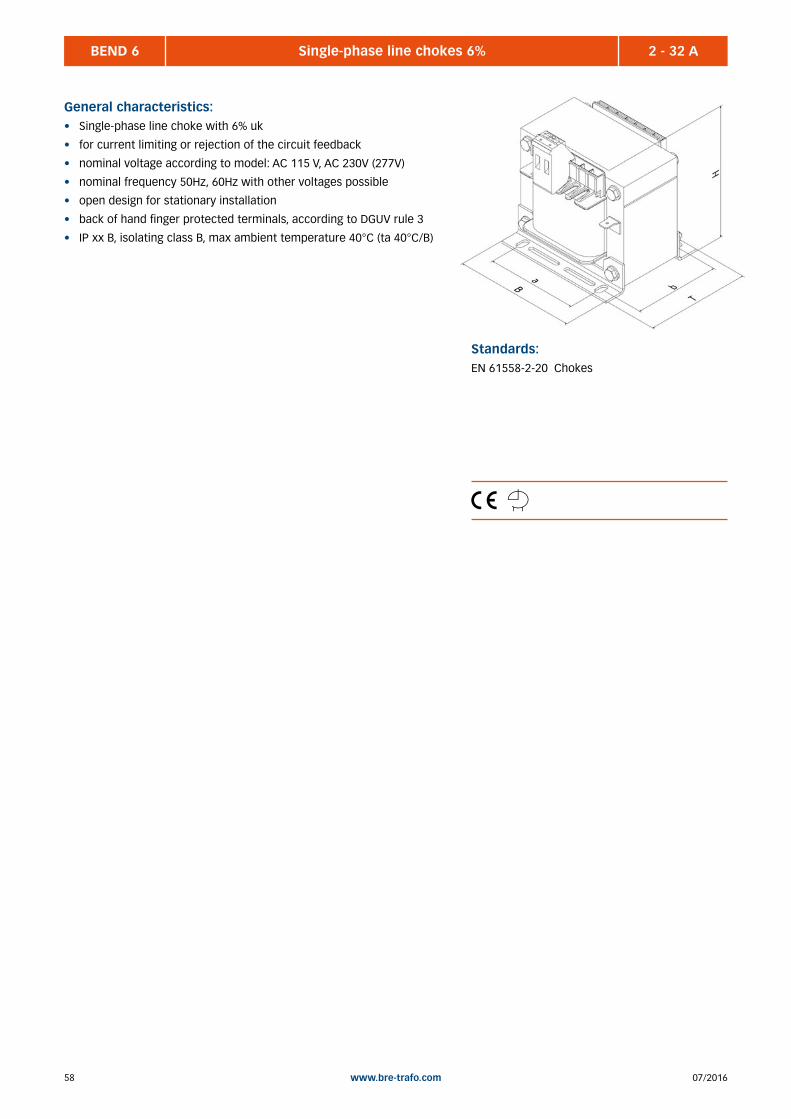
07/201658 www.bre-trafo.com
BEND 6 2 - 32 ASingle-phase line chokes 6%
General characteristics:• Single-phase line choke with 6% uk
• for current limiting or rejection of the circuit feedback
• nominal voltage according to model: AC 115 V, AC 230V (277V)
• nominal frequency 50Hz, 60Hz with other voltages possible
• open design for stationary installation
• back of hand finger protected terminals, according to DGUV rule 3
• IP xx B, isolating class B, max ambient temperature 40°C (ta 40°C/B)
Standards:EN 61558-2-20 Chokes

5907/2016 www.bre-trafo.com
BEND 6 2 - 32 ASingle-phase line chokes 6%
Model Art.-No. Current [A]
Inductance [mH] Size Copper
[kg] Total [kg]
Dimensions [mm]
B T H a b Screw
BEND6-4-115 0703-10-000004 4 5,49 EI 54/18 0,07 0,35 55 76 60 44 34 M3
BEND6-6-115 0703-10-000006 6 3,66 EI 60/21 0,10 0,50 60 65 76 44 36 M3
BEND6-8-115 0703-10-000008 8 2,74 EI 60/31 0,12 0,70 60 75 76 44 46 M3
BEND6-10-115 0703-10-000010 10 2,19 EI 66/23 0,15 0,70 66 67 80 50 40 M4
BEND6-13-115 0703-10-000013 13 1,69 EI 66/34 0,18 1,00 66 78 80 50 52 M4
BEND6-16-115 0703-10-000016 16 1,37 EI 78/27 0,21 1,10 78 71 89 56 45 M4
BEND6-20-115 0703-10-000020 20 1,09 EI 78/36 0,23 1,50 78 80 89 56 54 M4
BEND6-25-115 0703-10-000025 25 0,87 EI 84/43 0,26 1,90 85 68 93 64 47 M4BEND6-32-115 0703-10-000032 32 0,68 EI 84/43 0,34 2,00 85 68 93 64 47 M4
Voltage: AC 115 V
Model Art.-No. Current [A]
Inductance [mH] Size Copper
[kg] Total [kg]
Dimensions [mm]
B T H a b Screw
BEND6-2-230 0704-10-000002 2 21,69 EI 54/18 0,06 0,40 55 76 60 44 34 M3
BEND6-4-230 0704-10-000004 4 10,98 EI 60/31 0,10 0,70 60 75 76 44 46 M3
BEND6-6-230 0704-10-000006 6 7,32 EI 66/34 0,12 1,00 66 78 80 50 52 M4
BEND6-8-230 0704-10-000008 8 5,49 EI 66/34 0,25 1,10 66 78 80 50 52 M4
BEND6-10-230 0704-10-000010 10 4,39 EI 78/27 0,26 1,30 78 71 89 56 45 M4
BEND6-13-230 0704-10-000013 13 3,37 EI 78/36 0,33 1,50 78 80 89 56 54 M4
BEND6-16-230 0704-10-000016 16 2,74 EI 84/43 0,28 1,90 85 68 93 64 47 M4
BEND6-20-230 0704-10-000020 20 2,19 EI 84/52 0,41 2,40 85 90 93 64 69 M4
BEND6-25-230 0704-10-000025 25 1,75 EI 96/45 0,52 2,90 96 88 104 84 70 M5BEND6-32-230 0704-10-000032 32 1,37 EI 96/59 0,57 3,50 96 102 104 84 84 M5
Voltage: AC 230 V (50Hz) // 277 V (60Hz)

07/201660 www.bre-trafo.com
BENDD 4 2 - 32 ASingle-phase line dual chokes 4%
General characteristics:• Single-phase line dual chokes with 4% uk
• for current limiting or rejection of the circuit feedback
• nominal voltage according to model: AC 115 V, AC 230V (277V),
AC 400V (480V)
• nominal frequency 50Hz, 60Hz with other voltages possible
• open design for stationary installation
• back of hand finger protected terminals, according to DGUV rule 3
• IP xx B, isolating class B, max ambient temperature 40°C (ta 40°C/B)
Standards:EN 61558-2-20 Chokes

6107/2016 www.bre-trafo.com
BENDD 4 2 - 32 ASingle-phase line dual chokes 4%
Model Art.-No. Current [A]
Inductance [mH] Size Copper
[kg] Total [kg]
Dimensions [mm]
B T H a b Screw
BENDD4-2-115 0705-10-000002 2 3,66 EI 48/16 0,05 0,30 46 42 52 38 31 M3
BENDD4-4-115 0705-10-000004 4 1,83 EI 60/21 0,07 0,52 60 65 76 44 36 M3
BENDD4-6-115 0705-10-000006 6 1,22 EI 60/31 0,15 0,80 60 75 76 44 46 M3
BENDD4-8-115 0705-10-000008 8 0,915 EI 66/23 0,15 0,90 66 67 80 50 40 M4
BENDD4-10-115 0705-10-000010 10 0,732 EI 66/34 0,18 1,10 66 78 80 50 52 M4
BENDD4-13-115 0705-10-000013 13 0,563 EI 78/27 0,23 1,20 78 71 89 56 45 M4
BENDD4-16-115 0705-10-000016 16 0,457 EI 78/36 0,27 1,50 78 80 89 56 54 M4
BENDD4-20-115 0705-10-000020 20 0,366 EI 84/29 0,42 2,00 85 68 93 64 47 M4
BENDD4-25-115 0705-10-000025 25 0,293 EI 84/43 0,42 1,90 85 68 93 64 47 M4BENDD4-32-115 0705-10-000032 32 0,229 EI 96/35 0,49 2,50 96 78 104 84 60 M5
Voltage: AC 115 V
Model Art.-No. Current [A]
Inductance [mH] Size Copper
[kg] Total [kg]
Dimensions [mm]
B T H a b Screw
BENDD4-2-230 0706-10-000002 2 7,32 EI 54/18 0,09 0,40 55 76 60 44 34 M3
BENDD4-4-230 0706-10-000004 4 3,66 EI 60/31 0,14 0,80 60 75 76 44 46 M3
BENDD4-6-230 0706-10-000006 6 2,44 EI 78/27 0,20 1,20 78 71 89 56 45 M4
BENDD4-8-230 0706-10-000008 8 1,83 EI 78/36 0,23 1,50 78 80 89 56 54 M4
BENDD4-10-230 0706-10-000010 10 1,46 EI 84/43 0,21 1,90 85 68 93 64 47 M4
BENDD4-13-230 0706-10-000013 13 1,12 EI 84/43 0,35 2,00 85 68 93 64 47 M4
BENDD4-16-230 0706-10-000016 16 0,91 EI 84/52 0,47 2,40 85 90 93 64 69 M4
BENDD4-20-230 0706-10-000020 20 0,73 EI 96/45 0,58 2,80 96 88 104 84 70 M5
BENDD4-25-230 0706-10-000025 25 0,58 EI 96/59 0,74 3,70 96 102 104 84 84 M5BENDD4-32-230 0706-10-000032 32 0,45 EI 105/60 0,86 4,40 105 104 110 84 85 M5
Voltage: AC 230 V (50Hz) // 277 V (60Hz)
Model Art.-No. Current [A]
Inductance [mH] Size Copper
[kg] Total [kg]
Dimensions [mm]
B T H a b Screw
BENDD4-2-400 0707-10-000002 2 12,73 EI 60/31 0,12 0,80 60 75 76 44 46 M3
BENDD4-4-400 0707-10-000004 4 6,36 EI 78/27 0,25 1,20 78 71 89 56 45 M4
BENDD4-6-400 0707-10-000006 6 4,24 EI 84/29 0,39 2,00 85 54 93 64 47 M4
BENDD4-8-400 0707-10-000008 8 3,18 EI 84/43 0,29 2,10 85 68 93 64 47 M4
BENDD4-10-400 0707-10-000010 10 2,54 EI 96/45 0,42 2,80 96 88 104 84 70 M5
BENDD4-13-400 0707-10-000013 13 1,96 EI 96/59 0,36 3,70 96 102 104 84 84 M5
BENDD4-16-400 0707-10-000016 16 1,59 EI 105/45 0,63 3,70 105 88 110 84 69 M5
BENDD4-20-400 0707-10-000020 20 1,27 EI 105/60 0,81 4,40 105 104 110 84 85 M5
BENDD4-25-400 0707-10-000025 25 1,02 EI 120/53 1,05 5,40 120 100 120 90 82 M5BENDD4-32-400 0707-10-000032 32 0,79 EI 120/61 1,47 6,20 120 108 120 90 90 M5
Voltage: AC 400 V (50Hz) // AC 480 V (60Hz)
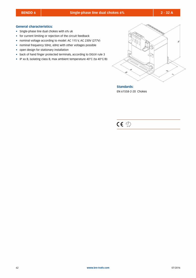
07/201662 www.bre-trafo.com
BENDD 6 2 - 32 ASingle-phase line dual chokes 6%
General characteristics:• Single-phase line dual chokes with 6% uk
• for current limiting or rejection of the circuit feedback
• nominal voltage according to model: AC 115 V, AC 230V (277V)
• nominal frequency 50Hz, 60Hz with other voltages possible
• open design for stationary installation
• back of hand finger protected terminals, according to DGUV rule 3
• IP xx B, isolating class B, max ambient temperature 40°C (ta 40°C/B)
Standards:EN 61558-2-20 Chokes

6307/2016 www.bre-trafo.com
BENDD 6 2 - 32 ASingle-phase line dual chokes 6%
Model Art.-No. Current [A]
Inductance [mH] Size Copper
[kg] Total [kg]
Dimensions [mm]
B T H a b Screw
BENDD6-2-115 0708-10-000002 2 5,49 EI 54/18 0,08 0,40 55 76 60 44 34 M3
BENDD6-4-115 0708-10-000004 4 2,74 EI 60/31 0,10 0,80 60 75 76 44 46 M3
BENDD6-6-115 0708-10-000006 6 1,83 EI 66/34 0,19 1,10 66 78 80 50 52 M4
BENDD6-8-115 0708-10-000008 8 1,37 EI 78/27 0,20 1,20 78 71 89 56 45 M4
BENDD6-10-115 0708-10-000010 10 1,10 EI 78/36 0,29 1,50 78 80 89 56 54 M4
BENDD6-13-115 0708-10-000013 13 0,84 EI 84/43 0,28 1,90 85 68 93 64 47 M4
BENDD6-16-115 0708-10-000016 16 0,68 EI 84/43 0,31 2,00 85 68 93 64 47 M4
BENDD6-20-115 0708-10-000020 20 0,55 EI 96/35 0,52 2,50 96 78 104 84 60 M5
BENDD6-25-115 0708-10-000025 25 0,44 EI 96/45 0,46 2,80 96 88 104 84 70 M5BENDD6-32-115 0708-10-000032 32 0,34 EI 96/59 0,80 3,70 96 102 104 84 84 M5
Voltage AC 115 V
Model Art.-No. Current [A]
Inductance [mH] Size Copper
[kg] Total [kg]
Dimensions [mm]
B T H a b Screw
BENDD6-2-230 0709-10-000002 2 10,98 EI 66/23 0,12 0,90 66 67 80 50 40 M4
BENDD6-4-230 0709-10-000004 4 5,49 EI 66/34 0,22 1,10 66 78 80 50 52 M4
BENDD6-6-230 0709-10-000006 6 3,66 EI 78/36 0,30 1,50 78 80 89 56 54 M4
BENDD6-8-230 0709-10-000008 8 2,74 EI 84/43 0,32 1,90 85 68 93 64 47 M4
BENDD6-10-230 0709-10-000010 10 2,19 EI 96/35 0,41 2,50 96 78 104 84 60 M5
BENDD6-13-230 0709-10-000013 13 1,67 EI 96/45 0,52 2,80 96 88 104 84 70 M5
BENDD6-16-230 0709-10-000016 16 1,37 EI 96/59 0,65 3,70 96 102 104 84 84 M5
BENDD6-20-230 0709-10-000020 20 1,10 EI 105/45 1,00 3,70 105 88 110 84 69 M5
BENDD6-25-230 0709-10-000025 25 0,88 EI 105/60 0,94 4,40 105 104 110 84 85 M5BENDD6-32-230 0709-10-000032 32 0,68 EI 120/53 1,38 5,40 120 100 120 90 82 M5
Voltage AC 230 V (50Hz) // 277 V (60Hz)
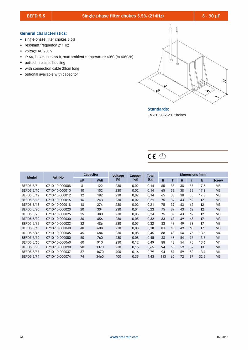
07/201664 www.bre-trafo.com
BEFD 5,5 8 - 90 µFSingle-phase filter chokes 5,5% (214Hz)
General characteristics:• single-phase filter chokes 5,5%
• resonant frequency 214 Hz
• voltage AC 230 V
• IP 64, isolation class B, max ambient temperature 40°C (ta 40°C/B)
• potted in plastic housing
• with connection cable 25cm long
• optional available with capacitor
Standards:EN 61558-2-20 Chokes
Model Art.-No.Capacitor Voltage
[V] Copper
[kg] Total [kg]
Dimensions [mm]
µF VAR B T H a b Screw
BEFD5,5/8 0710-10-000008 8 122 230 0,02 0,14 65 33 38 55 17,8 M3BEFD5,5/10 0710-10-000010 10 152 230 0,02 0,14 65 33 38 55 17,8 M3BEFD5,5/12 0710-10-000012 12 182 230 0,02 0,14 65 33 38 55 17,8 M3BEFD5,5/16 0710-10-000016 16 243 230 0,02 0,21 75 39 43 62 12 M3BEFD5,5/18 0710-10-000018 18 274 230 0,02 0,21 75 39 43 62 12 M3BEFD5,5/20 0710-10-000020 20 304 230 0,04 0,23 75 39 43 62 12 M3BEFD5,5/25 0710-10-000025 25 380 230 0,05 0,24 75 39 43 62 12 M3BEFD5,5/30 0710-10-000030 30 456 230 0,05 0,32 83 43 49 68 17 M3BEFD5,5/32 0710-10-000032 32 486 230 0,05 0,32 83 43 49 68 17 M3BEFD5,5/40 0710-10-000040 40 608 230 0,08 0,38 83 43 49 68 17 M3BEFD5,5/45 0710-10-000045 45 684 230 0,08 0,45 88 48 54 75 13,6 M4BEFD5,5/50 0710-10-000050 50 760 230 0,08 0,45 88 48 54 75 13,6 M4BEFD5,5/60 0710-10-000060 60 910 230 0,12 0,49 88 48 54 75 13,6 M4BEFD5,5/90 0710-10-000090 90 1370 230 0,15 0,65 94 50 59 82 13 M4BEFD5,5/37 0710-10-000037 37 1670 400 0,16 0,79 94 57 59 82 13,4 M4BEFD5,5/74 0710-10-000074 74 3460 400 0,35 1,43 113 60 72 97 32,5 M5

6507/2016 www.bre-trafo.com
BDFD 7 2,5 - 50 kVARThree-phases filter chokes 7% (189Hz)
Standards:EN 61558-2-20 Chokes
Model Art.-No. Current [A]
Power [kVAr]
Induc- tance [mH]
Capacity [µF] Size Copper
[kg] Total [kg]
Dimensions [mm]
B T H a b screw
BDFD7-2,5 0718-10-000002 3,90 2,50 14,20 3x 16,6 3UI 75/26 0,40 3,40 150 86 135 113 49 M5
BDFD7-3,1 0718-10-000003 4,70 3,10 11,90 3x 19,9 3UI 75/26 0,51 3,50 150 86 135 113 49 M5
BDFD7-5 0718-10-000005 7,80 5,00 7,12 3x 33,2 3UI 75/26 1,13 4,10 150 86 135 113 49 M5
BDFD7-6,3 0718-10-000006 9,70 6,30 5,70 3x 41,5 3UI 75/41 0,81 5,10 150 101 135 113 64 M5
BDFD7-7,5 0718-10-000007 11,6 7,50 4,76 3x 49,7 3UI 75/41 1,17 5,40 150 101 135 113 64 M5
BDFD7-10 0718-10-000010 15,5 10,0 3,55 3x 66,3 3UI 90/41 1,43 7,80 180 101 155 136 67 M6
BDFD7-12,5 0718-10-000012 18,0 12,5 3,07 3x 77,1 3UI 90/41 2,13 8,60 180 101 155 136 67 M6
BDFD7-15 0718-10-000015 23,3 15,0 2,37 3x 99,5 3UI 90/51 2,81 10,1 180 111 155 136 77 M6
BDFD7-16,7 0718-10-000016 24,1 16,7 2,30 3x 102,9 3UI 90/51 2,81 10,1 180 111 155 136 77 M6BDFD7-20 0718-10-000020 31,0 20,0 1,78 3x 132,6 3UI 114/64 2,42 15,5 228 134 195 176 95 M6
BDFD7-25 0718-10-000025 36,1 25,0 1,53 3x 154,2 3UI 114/64 3,22 16,3 228 134 260 176 95 M6
BDFD7-30 0718-10-000030 46,6 30,0 1,18 3x 198,9 3UI 120/71 4,11 21,1 240 141 270 185 101 M8
BDFD7-33,3 0718-10-000033 48,2 33,3 1,15 3x 205,8 3UI 120/71 4,11 21,1 240 141 270 185 101 M8
BDFD7-37,5 0718-10-000037 54,3 37,5 1,02 3x 213,9 3UI 132/72 4,08 26,3 265 152 300 200 102 M8
BDFD7-40 0718-10-000040 58,2 40,0 0,95 3x 248,8 3UI 132/72 5,45 27,8 265 152 300 200 102 M8
BDFD7-50 0718-10-000050 72,2 50,0 0,77 3x 308,4 3UI 150/77 5,19 35,3 300 165 320 224 120 M8
General characteristics:• three-phase filter chokes
• voltage drop 7%
• resonant frequency 189 Hz
• nominal voltage 3AC 400V - 50Hz
• max thermal current 1,22x nominal current
• linearity 1,8x nominal current
• open design for stationary installation
• back of hand finger protected terminals, according to DGUV rule 3
• IP xx B, isolating class B, max ambient temperature 40°C
(ta 40°C/B)
• optional available with capacitor
• other voltages, powers or resonant frequencies on request

07/201666 www.bre-trafo.com
BDFD 14 3,1 - 50 kVARThree-phases filter chokes 14% (134Hz)
Standards:EN 61558-2-20 Chokes
Model Art.-No. Current [A]
Power [kVAr]
Induc- tance [mH]
Capacity [µF] Size Copper
[kg] Total [kg]
Dimensions [mm]
B T H a b screw
BDFD14-3,1 0719-10-000003 4,20 3,10 28,3 3x 16,6 3UI 75/41 0,78 5,10 150 101 135 113 64 M5
BDFD14-6,3 0719-10-000006 9,10 6,30 13,1 3x 35,9 3UI 90/41 2,22 8,10 180 101 155 136 67 M6
BDFD14-7,5 0719-10-000007 11,0 7,50 10,8 3x 43,4 3UI 90/51 2,83 10,2 180 111 155 136 77 M6
BDFD14-10 0719-10-000010 15,1 10,0 7,86 3x 59,8 3UI 114/40 3,61 12,5 228 110 195 176 71 M6
BDFD14-12,5 0719-10-000012 18,1 12,5 6,59 3x 71,4 3UI 114/40 5,18 14,0 228 110 195 176 71 M6
BDFD14-15 0719-10-000015 22,7 15,0 5,25 3x 89,6 3UI 114/64 4,66 18,0 228 134 195 176 95 M6
BDFD14-16,7 0719-10-000016 24,2 16,7 4,91 3x 95,8 3UI 120/61 4,33 21,0 240 131 205 175 101 M8
BDFD14-20 0719-10-000020 28,6 20,0 4,16 3x 113,1 3UI 120/61 6,88 23,5 240 131 205 175 101 M8
BDFD14-25 0719-10-000025 36,1 25,0 3,29 3x 142,8 3UI 132/72 7,40 29,0 265 152 230 200 102 M8BDFD14-30 0719-10-000030 44,1 30,0 2,70 3x 174,3 3UI 132/72 10,4 32,0 265 152 230 200 102 M8
BDFD14-33,3 0719-10-000033 48,2 33,3 2,47 3x 190,7 3UI 132/72 11,9 33,5 265 152 300 200 102 M8
BDFD14-37,5 0719-10-000037 54,2 37,5 2,20 3x 214,2 3UI 150/77 10,9 40,5 300 165 330 224 120 M8
BDFD14-40 0719-10-000040 58,8 40,0 2,02 3x 232,4 3UI 150/77 12,3 42,0 300 165 330 224 120 M8
BDFD14-50 0719-10-000050 71,9 50,0 1,60 3x 285,6 3UI 150/92 15,4 45,5 300 180 330 224 134 M8
General characteristics:• three-phase filter chokes
• voltage drop 14%
• resonant frequency 134 Hz
• nominal voltage 3AC 400V - 50Hz
• max thermal current 1,15x nominal current
• open design for stationary installation
• back of hand finger protected terminals, according to DGUV rule 3
• IP xx B, isolating class B, max ambient temperature 40°C
(ta 40°C/B)
• optional available with capacitor
• other voltages, powers or resonant frequencies on request

6707/2016 www.bre-trafo.com
BDND 4 2 - 500 AThree-phase line chokes 4%
General characteristics:• three-phase line choke with 2% uk
• for current limiting or rejection of the circuit feedback
• nominal voltage 3AC 400 V (3AC 480V)
• nominal frequency 50Hz
• open design for stationary installation
• back of hand finger protected terminals, according to DGUV rule 3
• from 400A connection to cable lugs
• IPxxP, insulation class F, max ambient temperature
40°C (ta 40°C/F)
• other currents and voltages on request
Standards:EN 61558-2-20 Chokes
Model Art.-No. Current [A]
Inductance [mH] Size Copper
[kg] Total [kg]
Dimensions [mm]
B T H a b Screw
BDND4-2 0720-10-000002 2 14,64 3UI 48/26 0,05 1,30 96 86 100 71 48 M4
BDND4-4 0720-10-000004 4 7,32 3UI 48/26 0,15 1,40 96 86 100 71 48 M4
BDND4-6 0720-10-000006 6 4,88 3UI 48/26 0,34 1,50 96 86 100 71 48 M4
BDND4-8 0720-10-000008 8 3,66 3UI 60/21 0,50 1,50 120 81 110 90 39 M4
BDND4-10 0720-10-000010 10 2,93 3UI 60/21 0,70 1,70 120 81 110 90 39 M4
BDND4-13 0720-10-000013 13 2,25 3UI 60/31 0,62 2,30 120 91 110 90 49 M4
BDND4-16 0720-10-000016 16 1,83 3UI 75/26 0,80 3,60 150 86 135 113 49 M5
BDND4-20 0720-10-000020 20 1,46 3UI 75/26 1,05 3,80 150 86 135 113 49 M5
BDND4-25 0720-10-000025 25 1,17 3UI 75/41 0,92 5,10 150 101 135 113 64 M5BDND4-32 0720-10-000032 32 0,92 3UI 75/41 1,45 5,60 150 101 135 113 64 M5
BDND4-40 0720-10-000040 40 0,73 3UI 90/41 1,46 8,00 180 101 155 136 67 M6
BDND4-50 0720-10-000050 50 0,59 3UI 90/41 2,24 8,80 180 101 155 136 67 M6
BDND4-63 0720-10-000063 63 0,46 3UI 90/51 2,90 10,2 180 111 220 136 77 M6
BDND4-80 0720-10-000080 80 0,37 3UI 114/40 3,50 12,5 228 110 260 176 71 M6
BDND4-100 0720-10-000100 100 0,29 3UI 114/64 2,95 15,3 228 134 260 176 95 M6
BDND4-125 0720-10-000125 125 0,23 3UI 114/64 5,10 17,5 228 134 260 176 95 M6
BDND4-160 0720-10-000160 160 0,18 3UI 120/61 5,95 22,3 240 131 280 185 101 M8
BDND4-200 0720-10-000200 200 0,15 3UI 132/72 5,60 28,0 265 152 300 200 102 M8
BDND4-250 0720-10-000250 250 0,12 3UI 150/77 6,70 39,0 300 165 330 224 120 M8
BDND4-315 0720-10-000315 315 0,093 3UI 150/77 11,5 43,0 300 165 330 224 120 M8
BDND4-400 0720-10-000400 400 0,073 3UI 168/92 10,2 52,0 336 250 290 248 144 M8
BDND4-500 0720-10-000500 500 0,059 3UI 168/92 15,3 57,0 336 250 290 248 144 M8
Voltage 3AC 400 V (50Hz) // 3AC 480 V (60Hz)
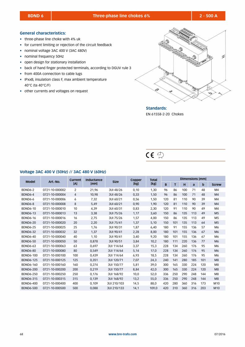
07/201668 www.bre-trafo.com
2 - 500 ABDND 6 Three-phase line chokes 6%
General characteristics:• three-phase line choke with 4% uk
• for current limiting or rejection of the circuit feedback
• nominal voltage 3AC 400 V (3AC 480V)
• nominal frequency 50Hz
• open design for stationary installation
• back of hand finger protected terminals, according to DGUV rule 3
• from 400A connection to cable lugs
• IPxxB, insulation class F, max ambient temperature
40°C (ta 40°C/F)
• other currents and voltages on request
Standards:EN 61558-2-20 Chokes
Model Art.-No. Current [A]
Inductance [mH] Size Copper
[kg] Total [kg]
Dimensions [mm]
B T H a b Screw
BDND6-2 0721-10-000002 2 21,96 3UI 48/26 0,10 1,30 96 86 100 71 48 M4
BDND6-4 0721-10-000004 4 10,98 3UI 48/26 0,33 1,50 96 86 100 71 48 M4
BDND6-6 0721-10-000006 6 7,32 3UI 60/21 0,56 1,50 120 81 110 90 39 M4
BDND6-8 0721-10-000008 8 5,49 3UI 60/21 0,90 1,90 120 81 110 90 39 M4
BDND6-10 0721-10-000010 10 4,39 3UI 60/31 0,83 2,30 120 91 110 90 49 M4
BDND6-13 0721-10-000013 13 3,38 3UI 75/26 1,17 3,60 150 86 135 113 49 M5
BDND6-16 0721-10-000016 16 2,75 3UI 75/26 1,57 4,00 150 86 135 113 49 M5
BDND6-20 0721-10-000020 20 2,20 3UI 75/41 1,37 5,10 150 101 135 113 64 M5
BDND6-25 0721-10-000025 25 1,76 3UI 90/31 1,87 6,40 180 91 155 136 57 M6BDND6-32 0721-10-000032 32 1,37 3UI 90/41 2,28 8,00 180 101 155 136 67 M6
BDND6-40 0721-10-000040 40 1,10 3UI 90/41 3,40 9,20 180 101 155 136 67 M6
BDND6-50 0721-10-000050 50 0,878 3UI 90/51 3,84 10,2 180 111 220 136 77 M6
BDND6-63 0721-10-000063 63 0,697 3UI 114/64 3,37 15,3 228 134 260 176 95 M6
BDND6-80 0721-10-000080 80 0,549 3UI 114/64 5,14 17,0 228 134 260 176 95 M6
BDND6-100 0721-10-000100 100 0,439 3UI 114/64 6,93 18,5 228 134 260 176 95 M6
BDND6-125 0721-10-000125 125 0,351 3UI 120/71 7,07 24,3 240 141 280 185 101 M8
BDND6-160 0721-10-000160 160 0,274 3UI 150/77 5,81 39,0 300 165 330 224 120 M8
BDND6-200 0721-10-000200 200 0,219 3UI 150/77 8,84 42,0 300 165 330 224 120 M8
BDND6-250 0721-10-000250 250 0,176 3UI 168/92 10,0 52,0 336 250 290 248 144 M8
BDND6-315 0721-10-000315 315 0,139 3UI 168/92 13,2 55,0 336 250 290 248 144 M8
BDND6-400 0721-10-000400 400 0,109 3UI 210/103 14,5 88,0 420 280 360 316 173 M10
BDND6-500 0721-10-000500 500 0,088 3UI 210/133 14,1 109,0 420 310 360 316 203 M10
Voltage 3AC 400 V (50Hz) // 3AC 480 V (60Hz)
6907/2016 www.bre-trafo.com
BERS 684 Single-phase variable toroidal auto transformers, model 684 ............................................................................ 74 BERS 757 Single-phase variable toroidal auto transformers, model 757 ............................................................................ 76 BERS 832 Single-phase variable toroidal auto transformers, model 832 ............................................................................ 78 BDRS 687 Three-phase variable toroidal auto transformers, model 687 ............................................................................. 80 BDRS 832 Three-phase variable toroidal auto transformers model 832 ............................................................................. 82 Accessories for variable toroidal auto transformers ........................................................................................... 84 BESKH Single-phase voltage stabilizer ............................................................................................................................ 86 BDSKH Three-phase voltage stabilizer ............................................................................................................................ 87
4 | VARIABLE TOROIDAL TRANSFORMERS
07/201670 www.bre-trafo.com
Generals
There where AC voltages and currents between 0 and 100 % of the nominal value are needed, variable transformers are
used.
The production of our toroidal transformers in accordance with EN 61558-2-14:
Particular requirements and tests for control transformers and power supply units that contain variable transformers.
Mounting and cooling
When installed in housing must be noted that the natural ventilation is not impeded. Even at rating excessive heating may
destroy the transformer.
At excess of the ambient temperature of 40 ° C , the rated current has to be reduced respectively 20% per 10 ° C increase
in temperature.
Especially, when used as a built-in transformers all relevant safety regulations (VDE , EN , IEC , equipment protection ,
etc.) have to be observed. This is part of our warranty conditions and must be detected by the user in case of damage.
Connection and overload protection
For three-phase variable toroidal transformers with star connection the neutral point is brought out in isolation. Is not al-
lowed to form an artificial neutral point. The Input side of the overload protection device can’t protect a variable toroidal
transformer, because of the variable gear ratio. In addition, the inrush current of the transformer has to be considered. At
the beginning it can do 20 to 30 times more than rated current and is disappears within some milliseconds.
Variable transformers can only be arranged by one, in the output circuit attuned to the rated current of the transformer
overload protection. This is the only way to protect a variable transformer. The tripping characteristic of the protective
device has to be noticed.
Circuits
As a standard circuit, the economy circuit has proven, i.e. that is a conducting connection between input and output
circuit. On the network side existing protection measures, such as. Line protection system , grounding and fault protec-
tion circuit will not be affected. Unit design frame, chassis or housing can be included directly into the existing protection
system.
For networks without neutral conductor , special versions are available on request. Also, variable transformers with
galvanic isolation are available.
4 | Variable toroidal transformers

7107/2016 www.bre-trafo.com
4 | Variable toroidal transformers
Maintenance
The maintenance has to be completed, depending on load at regular intervals, but at at least every 12 months, as follows:
• visual inspection of all mechanical and electrical parts
• inspection of the connections for tightness
• remove dust deposition of the winding by using a brush or compressed air
• cleaning the contact path possibly anticipated by a polishing abrasive pad , then with a soft lint-free cloth soaked in
isopropyl alcohol. Do not use mechanical abrasives.
• Check carbon rollers and storage for smooth operation and impression. Note: The storage of carbon rollers must not
be lubricated.
Warning!
Touching the electrical parts may be fatal! Before starting the maintenance work, electrical parts must necessarily be
unlocked!

07/201672 www.bre-trafo.com
Company _________________________________________________________________________________
Street _________________________________________________________________________________
Zip code, city _________________________________________________________________________________
Contact person _________________________________________________________________________________
Phone _________________________________________________________________________________
Mail _________________________________________________________________________________
Pieces _________________________________________________________________________________
Single-phase voltage stabilizer Three-phase voltage stabilizer (single-phase regulation)
Three-phase voltage stabilizer (master phase regulation)
Power _________________________________________________________________________________
Input voltage _________________________________________________________________________________
Neutral wire at input side available yes no
Tolerance (positive) +5% +10% +15% +20%
maximum voltage _______________ others ______________ __________________
Tolerance (negative) -5% -10% -15% -20%
minimum voltage _______________ others ______________ __________________
Output voltage _________________________________________________________________________________
Galvanic isolation yes no
Executed neutral wire yes no
Tolerance +/- 1% +/- 5% others _______________ _________________
Output current _________________________________________________________________________________
Frequency 50/60 Hz 60 Hz others _________________________________
Protection class IP 23 IP 54 others _________________________________
Application form for voltage stabilizer (page 1)
4 | Variable toroidal transformers
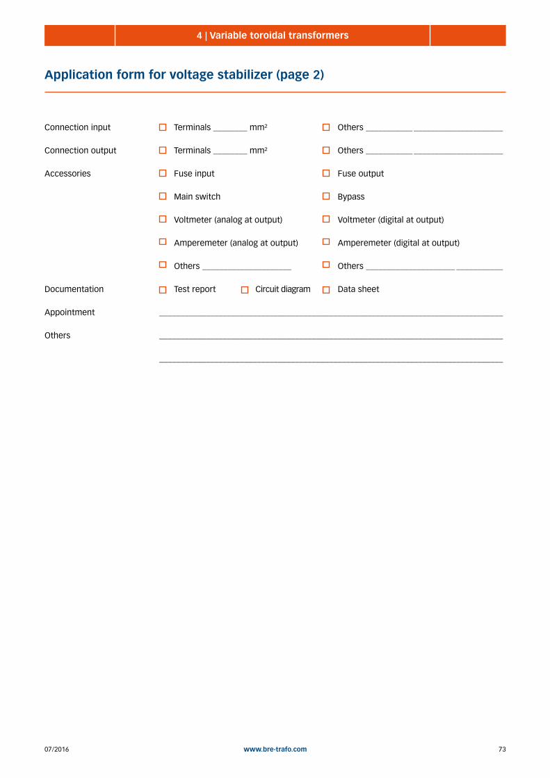
7307/2016 www.bre-trafo.com
Connection input Terminals ________ mm² Others ___________ _____________________
Connection output Terminals ________ mm² Others ___________ _____________________
Accessories Fuse input Fuse output
Main switch Bypass
Voltmeter (analog at output) Voltmeter (digital at output)
Amperemeter (analog at output) Amperemeter (digital at output)
Others _____________________ Others _____________________ ___________
Documentation Test report Circuit diagram Data sheet
Appointment _________________________________________________________________________________
Others _________________________________________________________________________________
_________________________________________________________________________________
Application form for voltage stabilizer (page 2)
4 | Variable toroidal transformers
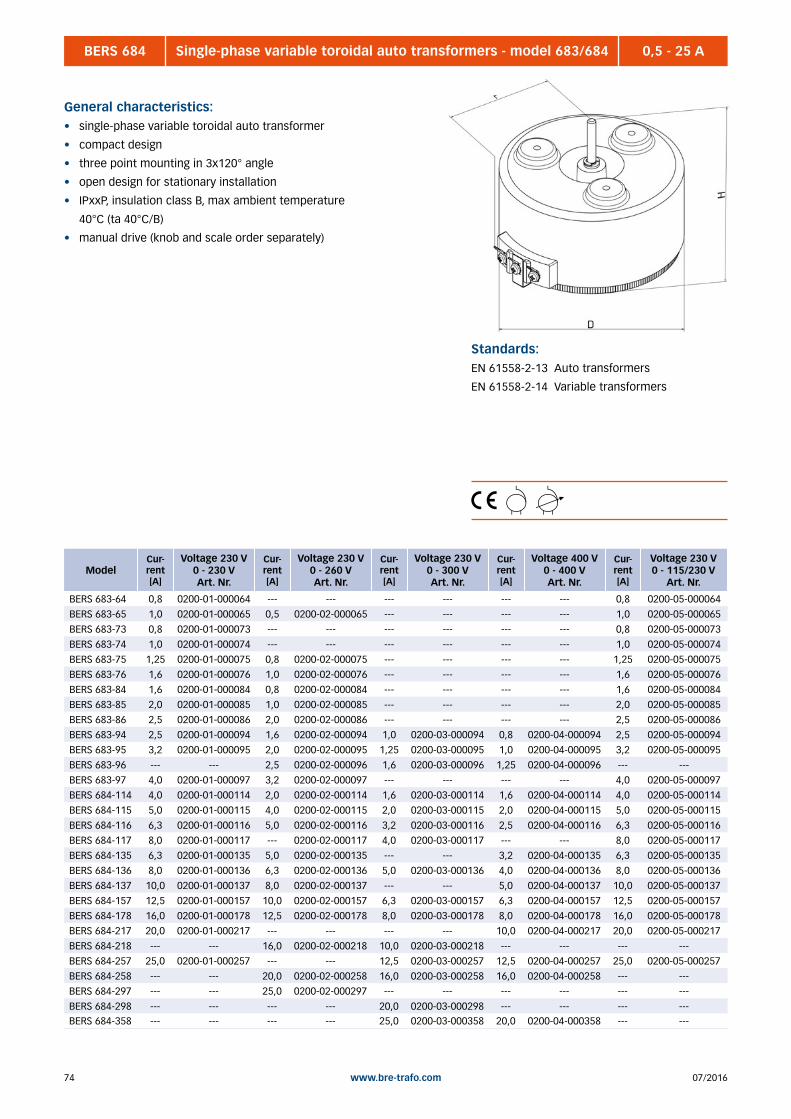
07/201674 www.bre-trafo.com
BERS 684 0,5 - 25 ASingle-phase variable toroidal auto transformers - model 683/684
General characteristics:• single-phase variable toroidal auto transformer
• compact design
• three point mounting in 3x120° angle
• open design for stationary installation
• IPxxP, insulation class B, max ambient temperature
40°C (ta 40°C/B)
• manual drive (knob and scale order separately)
Standards:EN 61558-2-13 Auto transformers
EN 61558-2-14 Variable transformers
ModelCur-rent [A]
Voltage 230 V0 - 230 VArt. Nr.
Cur-rent [A]
Voltage 230 V0 - 260 VArt. Nr.
Cur-rent [A]
Voltage 230 V0 - 300 VArt. Nr.
Cur-rent [A]
Voltage 400 V0 - 400 VArt. Nr.
Cur-rent [A]
Voltage 230 V0 - 115/230 V
Art. Nr.
BERS 683-64 0,8 0200-01-000064 --- --- --- --- --- --- 0,8 0200-05-000064
BERS 683-65 1,0 0200-01-000065 0,5 0200-02-000065 --- --- --- --- 1,0 0200-05-000065
BERS 683-73 0,8 0200-01-000073 --- --- --- --- --- --- 0,8 0200-05-000073
BERS 683-74 1,0 0200-01-000074 --- --- --- --- --- --- 1,0 0200-05-000074
BERS 683-75 1,25 0200-01-000075 0,8 0200-02-000075 --- --- --- --- 1,25 0200-05-000075
BERS 683-76 1,6 0200-01-000076 1,0 0200-02-000076 --- --- --- --- 1,6 0200-05-000076
BERS 683-84 1,6 0200-01-000084 0,8 0200-02-000084 --- --- --- --- 1,6 0200-05-000084
BERS 683-85 2,0 0200-01-000085 1,0 0200-02-000085 --- --- --- --- 2,0 0200-05-000085
BERS 683-86 2,5 0200-01-000086 2,0 0200-02-000086 --- --- --- --- 2,5 0200-05-000086
BERS 683-94 2,5 0200-01-000094 1,6 0200-02-000094 1,0 0200-03-000094 0,8 0200-04-000094 2,5 0200-05-000094
BERS 683-95 3,2 0200-01-000095 2,0 0200-02-000095 1,25 0200-03-000095 1,0 0200-04-000095 3,2 0200-05-000095
BERS 683-96 --- --- 2,5 0200-02-000096 1,6 0200-03-000096 1,25 0200-04-000096 --- ---
BERS 683-97 4,0 0200-01-000097 3,2 0200-02-000097 --- --- --- --- 4,0 0200-05-000097
BERS 684-114 4,0 0200-01-000114 2,0 0200-02-000114 1,6 0200-03-000114 1,6 0200-04-000114 4,0 0200-05-000114
BERS 684-115 5,0 0200-01-000115 4,0 0200-02-000115 2,0 0200-03-000115 2,0 0200-04-000115 5,0 0200-05-000115
BERS 684-116 6,3 0200-01-000116 5,0 0200-02-000116 3,2 0200-03-000116 2,5 0200-04-000116 6,3 0200-05-000116
BERS 684-117 8,0 0200-01-000117 --- 0200-02-000117 4,0 0200-03-000117 --- --- 8,0 0200-05-000117
BERS 684-135 6,3 0200-01-000135 5,0 0200-02-000135 --- --- 3,2 0200-04-000135 6,3 0200-05-000135
BERS 684-136 8,0 0200-01-000136 6,3 0200-02-000136 5,0 0200-03-000136 4,0 0200-04-000136 8,0 0200-05-000136
BERS 684-137 10,0 0200-01-000137 8,0 0200-02-000137 --- --- 5,0 0200-04-000137 10,0 0200-05-000137
BERS 684-157 12,5 0200-01-000157 10,0 0200-02-000157 6,3 0200-03-000157 6,3 0200-04-000157 12,5 0200-05-000157
BERS 684-178 16,0 0200-01-000178 12,5 0200-02-000178 8,0 0200-03-000178 8,0 0200-04-000178 16,0 0200-05-000178
BERS 684-217 20,0 0200-01-000217 --- --- --- --- 10,0 0200-04-000217 20,0 0200-05-000217
BERS 684-218 --- --- 16,0 0200-02-000218 10,0 0200-03-000218 --- --- --- ---
BERS 684-257 25,0 0200-01-000257 --- --- 12,5 0200-03-000257 12,5 0200-04-000257 25,0 0200-05-000257
BERS 684-258 --- --- 20,0 0200-02-000258 16,0 0200-03-000258 16,0 0200-04-000258 --- ---
BERS 684-297 --- --- 25,0 0200-02-000297 --- --- --- --- --- ---
BERS 684-298 --- --- --- --- 20,0 0200-03-000298 --- --- --- ---BERS 684-358 --- --- --- --- 25,0 0200-03-000358 20,0 0200-04-000358 --- ---

7507/2016 www.bre-trafo.com
Model Copper[kg]
Total [kg]
Dimensions [mm]
D H Ø Mount. 3x120° Screw Ø Shaft r
BERS 683-64 0,04 1,10 76 66 26 M4 6 54
BERS 683-65 0,05 1,30 76 76 26 M4 6 54
BERS 683-73 0,04 1,30 98 82 26 M4 6 71
BERS 683-74 0,05 1,40 98 85 26 M4 6 71
BERS 683-75 0,08 1,70 98 96 26 M4 6 71
BERS 683-76 0,10 2,00 98 106 26 M4 6 71
BERS 683-84 0,09 1,80 108 86 26 M4 6 76
BERS 683-85 0,12 2,10 98 76 26 M4 6 64
BERS 683-86 0,16 2,60 98 86 26 M4 6 64
BERS 683-94 0,14 2,30 118 96 26 M4 6 82
BERS 683-95 0,25 2,80 108 78 26 M4 6 70
BERS 683-96 0,30 3,40 108 88 26 M4 6 70
BERS 683-97 0,37 3,90 108 117 80 M6 6 70
BERS 684-114 0,30 3,40 145 105 80 M6 6 88
BERS 684-115 0,37 4,20 135 95 80 M6 6 83
BERS 684-116 0,45 5,00 135 106 80 M6 6 83
BERS 684-117 0,60 5,80 135 127 80 M6 6 83
BERS 684-135 0,55 5,20 150 112 110 M8 10 92
BERS 684-136 0,85 6,20 150 122 110 M8 10 92
BERS 684-137 1,00 7,40 150 132 110 M8 10 92
BERS 684-157 1,30 9,80 175 135 110 M8 10 110
BERS 684-178 1,60 13,5 195 152 110 M8 10 120
BERS 684-217 2,20 16,0 235 155 150 M8 10 145
BERS 684-218 2,40 18,0 235 165 150 M8 10 145
BERS 684-257 3,10 19,0 280 155 150 M8 10 160
BERS 684-258 3,30 21,0 280 165 150 M8 10 160
BERS 684-297 4,50 27,0 320 160 150 M8 10 200
BERS 684-298 4,80 28,0 320 180 150 M8 10 200BERS 684-358 5,60 34,0 390 180 150 M10 10 230
BERS 684 0,5 - 25 ASingle-phase variable toroidal auto transformers - model 683/684

07/201676 www.bre-trafo.com
BERS 757 0,8 - 16 ASingle-phase variable toroidal auto transformers - model 757
General characteristics:• single-phase follow controller
• compact design
• control electronics (MPRP2010) with motor drive
as standard
• open design for stationary installation
• IPxxB, insulation class B, max ambient
temperature 40°C (ta 40°C/B)
Standards:EN 61558-2-13 Auto transformers
EN 61558-2-14 Variable transformers
ModelCur-rent [A]
Voltage 230 V0 - 230 VArt. Nr.
Cur-rent [A]
Voltage 230 V0 - 260 VArt. Nr.
Cur-rent [A]
Voltage 230 V0 - 300 VArt. Nr.
Cur-rent [A]
Voltage 400 V0 - 400 VArt. Nr.
Cur-rent [A]
Voltage 230 V0 - 115/230 V
Art. Nr.
BERS 757-84 1,6 0201-01-000084 0,8 0201-02-000084 --- --- --- --- 1,6 0201-05-000084
BERS 757-85 2,0 0201-01-000085 1,0 0201-02-000085 --- --- --- --- 2,0 0201-05-000085
BERS 757-86 2,5 0201-01-000086 2,0 0201-02-000086 --- --- --- --- 2,5 0201-05-000086
BERS 757-94 2,5 0201-01-000094 1,6 0201-02-000094 1,0 0201-03-000094 0,8 0201-04-000094 2,5 0201-05-000094
BERS 757-95 3,2 0201-01-000095 2,0 0201-02-000095 1,25 0201-03-000095 1,0 0201-04-000095 3,2 0201-05-000095
BERS 757-96 --- --- 2,5 0201-02-000096 1,6 0201-03-000096 1,25 0201-04-000096 --- ---
BERS 757-97 4,0 0201-01-000097 3,2 0201-02-000097 --- --- --- --- 4,0 0201-05-000097
BERS 757-114 4,0 0201-01-000114 2,0 0201-02-000114 1,6 0201-03-000114 1,6 0201-04-000114 4,0 0201-05-000114
BERS 757-115 5,0 0201-01-000115 4,0 0201-02-000115 2,0 0201-03-000115 2,0 0201-04-000115 5,0 0201-05-000115
BERS 757-116 6,3 0201-01-000116 5,0 0201-02-000116 3,2 0201-03-000116 2,5 0201-04-000116 6,3 0201-05-000116
BERS 757-117 8,0 0201-01-000117 --- 0201-02-000117 4,0 0201-03-000117 --- --- 8,0 0201-05-000117
BERS 757-135 6,3 0201-01-000135 5,0 0201-02-000135 --- --- 3,2 0201-04-000135 6,3 0201-05-000135
BERS 757-136 8,0 0201-01-000136 6,3 0201-02-000136 5,0 0201-03-000136 4,0 0201-04-000136 8,0 0201-05-000136
BERS 757-137 10,0 0201-01-000137 8,0 0201-02-000137 --- --- 5,0 0201-04-000137 10,0 0201-05-000137
BERS 757-157 12,5 0201-01-000157 10,0 0201-02-000157 6,3 0201-03-000157 6,3 0201-04-000157 12,5 0201-05-000157
BERS 757-178 16,0 0201-01-000178 12,5 0201-02-000178 8,0 0201-03-000178 8,0 0201-04-000178 16,0 0201-05-000178
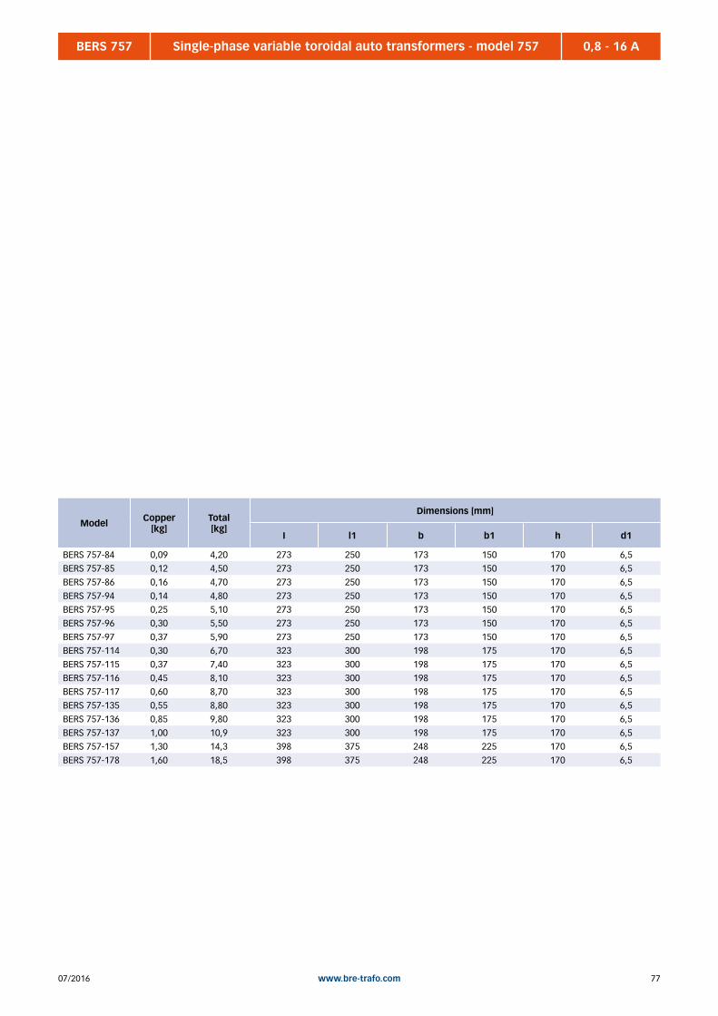
7707/2016 www.bre-trafo.com
BERS 757 0,8 - 16 ASingle-phase variable toroidal auto transformers - model 757
Model Copper[kg]
Total [kg]
Dimensions [mm]
I l1 b b1 h d1
BERS 757-84 0,09 4,20 273 250 173 150 170 6,5
BERS 757-85 0,12 4,50 273 250 173 150 170 6,5
BERS 757-86 0,16 4,70 273 250 173 150 170 6,5
BERS 757-94 0,14 4,80 273 250 173 150 170 6,5
BERS 757-95 0,25 5,10 273 250 173 150 170 6,5
BERS 757-96 0,30 5,50 273 250 173 150 170 6,5
BERS 757-97 0,37 5,90 273 250 173 150 170 6,5
BERS 757-114 0,30 6,70 323 300 198 175 170 6,5
BERS 757-115 0,37 7,40 323 300 198 175 170 6,5
BERS 757-116 0,45 8,10 323 300 198 175 170 6,5
BERS 757-117 0,60 8,70 323 300 198 175 170 6,5
BERS 757-135 0,55 8,80 323 300 198 175 170 6,5
BERS 757-136 0,85 9,80 323 300 198 175 170 6,5
BERS 757-137 1,00 10,9 323 300 198 175 170 6,5
BERS 757-157 1,30 14,3 398 375 248 225 170 6,5
BERS 757-178 1,60 18,5 398 375 248 225 170 6,5
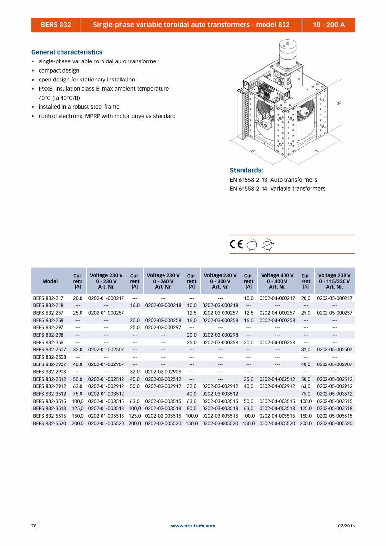
07/201678 www.bre-trafo.com
BERS 832 10 - 200 ASingle-phase variable toroidal auto transformers - model 832
General characteristics:• single-phase variable toroidal auto transformer
• compact design
• open design for stationary installation
• IPxxB, insulation class B, max ambient temperature
40°C (ta 40°C/B)
• installed in a robust steel frame
• control electronic MPRP with motor drive as standard
Standards:EN 61558-2-13 Auto transformers
EN 61558-2-14 Variable transformers
ModelCur-rent [A]
Voltage 230 V0 - 230 VArt. Nr.
Cur-rent [A]
Voltage 230 V0 - 260 VArt. Nr.
Cur-rent [A]
Voltage 230 V0 - 300 VArt. Nr.
Cur-rent [A]
Voltage 400 V0 - 400 VArt. Nr.
Cur-rent [A]
Voltage 230 V0 - 115/230 V
Art. Nr.
BERS 832-217 20,0 0202-01-000217 --- --- --- --- 10,0 0202-04-000217 20,0 0202-05-000217
BERS 832-218 --- --- 16,0 0202-02-000218 10,0 0202-03-000218 --- --- --- ---
BERS 832-257 25,0 0202-01-000257 --- --- 12,5 0202-03-000257 12,5 0202-04-000257 25,0 0202-05-000257
BERS 832-258 --- --- 20,0 0202-02-000258 16,0 0202-03-000258 16,0 0202-04-000258 --- ---
BERS 832-297 --- --- 25,0 0202-02-000297 --- --- --- --- --- ---
BERS 832-298 --- --- --- --- 20,0 0202-03-000298 --- --- --- ---
BERS 832-358 --- --- --- --- 25,0 0202-03-000358 20,0 0202-04-000358 --- ---
BERS 832-2507 32,0 0202-01-002507 --- --- --- --- --- --- 32,0 0202-05-002507
BERS 832-2508 --- --- --- --- --- --- --- --- --- ---
BERS 832-2907 40,0 0202-01-002907 --- --- --- --- --- --- 40,0 0202-05-002907
BERS 832-2908 --- --- 32,0 0202-02-002908 --- --- --- --- --- ---
BERS 832-2512 50,0 0202-01-002512 40,0 0202-02-002512 --- --- 25,0 0202-04-002512 50,0 0202-05-002512
BERS 832-2912 63,0 0202-01-002912 50,0 0202-02-002912 32,0 0202-03-002912 40,0 0202-04-002912 63,0 0202-05-002912
BERS 832-3512 75,0 0202-01-003512 --- --- 40,0 0202-03-003512 --- --- 75,0 0202-05-003512
BERS 832-3515 100,0 0202-01-003515 63,0 0202-02-003515 63,0 0202-03-003515 50,0 0202-04-003515 100,0 0202-05-003515
BERS 832-3518 125,0 0202-01-003518 100,0 0202-02-003518 80,0 0202-03-003518 63,0 0202-04-003518 125,0 0202-05-003518
BERS 832-5515 150,0 0202-01-005515 125,0 0202-02-005515 100,0 0202-03-005515 100,0 0202-04-005515 150,0 0202-05-005515
BERS 832-5520 200,0 0202-01-005520 200,0 0202-02-005520 150,0 0202-03-005520 150,0 0202-04-005520 200,0 0202-05-005520

7907/2016 www.bre-trafo.com
BERS 832 10 - 200 ASingle-phase variable toroidal auto transformers - model 832
Model Copper[kg]
Total [kg]
Dimensions [mm]
B T H
BERS 832-217 2,17 18,4 240 240 218
BERS 832-218 2,27 19,4 240 240 218
BERS 832-257 3,17 22,0 315 315 218
BERS 832-258 3,27 23,3 315 315 218
BERS 832-297 4,50 29,3 315 315 218
BERS 832-298 4,60 30,0 315 315 218
BERS 832-358 5,50 36,7 390 390 218
BERS 832-2507 3,27 23,4 390 390 243
BERS 832-2508 3,90 26,0 390 390 243
BERS 832-2907 4,50 29,4 390 390 243
BERS 832-2908 4,70 30,0 390 390 243
BERS 832-2512 6,00 46,7 390 390 320
BERS 832-2912 8,00 53,4 390 390 320
BERS 832-3512 12,5 80,0 465 465 320
BERS 832-3515 14,0 86,7 465 465 370
BERS 832-3518 16,3 100 465 465 420
BERS 832-5515 35,4 187 620 620 520
BERS 832-5520 50,7 250 620 620 520
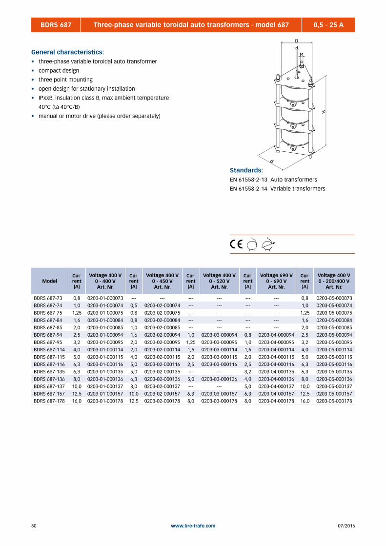
07/201680 www.bre-trafo.com
BDRS 687 0,5 - 25 AThree-phase variable toroidal auto transformers - model 687
General characteristics:• three-phase variable toroidal auto transformer
• compact design
• three point mounting
• open design for stationary installation
• IPxxB, insulation class B, max ambient temperature
40°C (ta 40°C/B)
• manual or motor drive (please order separately)
Standards:EN 61558-2-13 Auto transformers
EN 61558-2-14 Variable transformers
ModelCur-rent [A]
Voltage 400 V0 - 400 VArt. Nr.
Cur-rent [A]
Voltage 400 V0 - 450 VArt. Nr.
Cur-rent [A]
Voltage 400 V0 - 520 VArt. Nr.
Cur-rent [A]
Voltage 690 V0 - 690 VArt. Nr.
Cur-rent [A]
Voltage 400 V0 - 200/400 V
Art. Nr.
BDRS 687-73 0,8 0203-01-000073 --- --- --- --- --- --- 0,8 0203-05-000073
BDRS 687-74 1,0 0203-01-000074 0,5 0203-02-000074 --- --- --- --- 1,0 0203-05-000074
BDRS 687-75 1,25 0203-01-000075 0,8 0203-02-000075 --- --- --- --- 1,25 0203-05-000075
BDRS 687-84 1,6 0203-01-000084 0,8 0203-02-000084 --- --- --- --- 1,6 0203-05-000084
BDRS 687-85 2,0 0203-01-000085 1,0 0203-02-000085 --- --- --- --- 2,0 0203-05-000085
BDRS 687-94 2,5 0203-01-000094 1,6 0203-02-000094 1,0 0203-03-000094 0,8 0203-04-000094 2,5 0203-05-000094
BDRS 687-95 3,2 0203-01-000095 2,0 0203-02-000095 1,25 0203-03-000095 1,0 0203-04-000095 3,2 0203-05-000095
BDRS 687-114 4,0 0203-01-000114 2,0 0203-02-000114 1,6 0203-03-000114 1,6 0203-04-000114 4,0 0203-05-000114
BDRS 687-115 5,0 0203-01-000115 4,0 0203-02-000115 2,0 0203-03-000115 2,0 0203-04-000115 5,0 0203-05-000115
BDRS 687-116 6,3 0203-01-000116 5,0 0203-02-000116 2,5 0203-03-000116 2,5 0203-04-000116 6,3 0203-05-000116
BDRS 687-135 6,3 0203-01-000135 5,0 0203-02-000135 --- --- 3,2 0203-04-000135 6,3 0203-05-000135
BDRS 687-136 8,0 0203-01-000136 6,3 0203-02-000136 5,0 0203-03-000136 4,0 0203-04-000136 8,0 0203-05-000136
BDRS 687-137 10,0 0203-01-000137 8,0 0203-02-000137 --- --- 5,0 0203-04-000137 10,0 0203-05-000137
BDRS 687-157 12,5 0203-01-000157 10,0 0203-02-000157 6,3 0203-03-000157 6,3 0203-04-000157 12,5 0203-05-000157BDRS 687-178 16,0 0203-01-000178 12,5 0203-02-000178 8,0 0203-03-000178 8,0 0203-04-000178 16,0 0203-05-000178

8107/2016 www.bre-trafo.com
BDRS 687 0,5 - 25 AThree-phase variable toroidal auto transformers - model 687
Model Copper[kg]
Total [kg]
Dimensions [mm]
G H D M d
BDRS 687-73 0,11 5,50 155 300 140 M10 6
BDRS 687-74 0,12 5,80 155 300 140 M10 6
BDRS 687-75 0,21 6,50 155 320 140 M10 6
BDRS 687-84 0,27 6,70 155 300 140 M10 6
BDRS 687-85 0,36 7,40 155 320 140 M10 6
BDRS 687-94 0,48 7,90 155 300 140 M10 6
BDRS 687-95 0,75 9,50 155 320 140 M10 6
BDRS 687-114 0,90 11,5 175 330 160 M10 6
BDRS 687-115 1,11 14,0 175 360 160 M10 6
BDRS 687-116 1,35 16,5 175 390 160 M10 6
BDRS 687-135 2,10 21,0 240 405 220 M12 10
BDRS 687-136 2,70 24,0 240 435 220 M12 10
BDRS 687-137 3,00 27,0 240 485 220 M12 10
BDRS 687-157 3,60 30,0 240 485 220 M12 10BDRS 687-178 4,80 44,0 260 535 240 M16 10
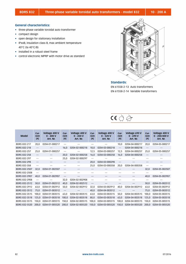
07/201682 www.bre-trafo.com
BDRS 832 10 - 200 AThree-phase variable toroidal auto transformers - model 832
General characteristics:• three-phase variable toroidal auto transformer
• compact design
• open design for stationary installation
• IPxxB, insulation class B, max ambient temperature
40°C (ta 40°C/B)
• installed in a robust steel frame
• control electronic MPRP with motor drive as standard
Standards:EN 61558-2-13 Auto transformers
EN 61558-2-14 Variable transformers
ModelCur-rent [A]
Voltage 400 V0 - 400 VArt. Nr.
Cur-rent [A]
Voltage 400 V0 - 450 VArt. Nr.
Cur-rent [A]
Voltage 400 V0 - 520 VArt. Nr.
Cur-rent [A]
Voltage 690 V0 - 690 VArt. Nr.
Cur-rent [A]
Voltage 400 V0 - 200/400 V
Art. Nr.
BDRS 832-217 20,0 0204-01-000217 --- --- --- --- 10,0 0204-04-000217 20,0 0204-05-000217
BDRS 832-218 --- --- 16,0 0204-02-000218 10,0 0204-03-000218 --- 0204-04-000218 --- ---
BDRS 832-257 25,0 0204-01-000257 --- --- 12,5 0204-03-000257 12,5 0204-04-000257 25,0 0204-05-000257
BDRS 832-258 --- --- 20,0 0204-02-000258 16,0 0204-03-000258 16,0 0204-04-000258 --- ---
BDRS 832-297 --- --- 25,0 0204-02-000297 --- --- --- --- --- ---
BDRS 832-298 --- --- --- --- 20,0 0204-03-000298 --- --- --- ---
BDRS 832-358 --- --- --- --- 25,0 0204-03-000358 20,0 0204-04-000358 --- ---
BDRS 832-2507 32,0 0204-01-002507 --- --- --- --- --- --- 32,0 0204-05-002507
BDRS 832-2508 --- --- --- --- --- --- --- --- --- ---
BDRS 832-2907 40,0 0204-01-002907 --- --- --- --- --- --- 40,0 0204-05-002907
BDRS 832-2908 --- --- 32,0 0204-02-002908 --- --- --- --- --- ---
BDRS 832-2512 50,0 0204-01-002512 40,0 0204-02-002512 --- --- --- --- 50,0 0204-05-002512
BDRS 832-2912 63,0 0204-01-002912 50,0 0204-02-002912 32,0 0204-03-002912 40,0 0204-04-002912 63,0 0204-05-002912
BDRS 832-3512 75,0 0204-01-003512 --- --- 40,0 0204-04-003512 --- --- 75,0 0204-05-003512
BDRS 832-3515 100,0 0204-01-003515 63,0 0204-02-003515 63,0 0204-03-003515 50,0 0204-04-003515 100,0 0204-05-003515
BDRS 832-3518 125,0 0204-01-003518 100,0 0204-02-003518 80,0 0204-03-003518 63,0 0204-04-003518 125,0 0204-05-003518
BDRS 832-5515 150,0 0204-01-005515 150,0 0204-02-005515 100,0 0204-03-005515 100,0 0204-04-005515 150,0 0204-05-005515
BDRS 832-5520 200,0 0204-01-005520 200,0 0204-02-005520 150,0 0204-03-005520 150,0 0204-04-005520 200,0 0204-05-005520

8307/2016 www.bre-trafo.com
BDRS 832 10 - 200 AThree-phase variable toroidal auto transformers - model 832
Model Copper[kg]
Total [kg]
Dimensions [mm]
B T H
BDRS 832-217 6,51 55,0 240 240 618
BDRS 832-218 6,80 58,0 240 240 618
BDRS 832-257 9,50 66,0 315 315 618
BDRS 832-258 9,80 70,0 315 315 618
BDRS 832-297 13,5 88,0 315 315 618
BDRS 832-298 13,8 90,0 315 315 618
BDRS 832-358 16,5 110 390 390 620
BDRS 832-2507 9,80 70,0 390 390 695
BDRS 832-2508 11,7 78,0 390 390 695
BDRS 832-2907 13,5 88,0 390 390 695
BDRS 832-2908 13,8 90,0 390 390 695
BDRS 832-2512 18,0 140 390 390 920
BDRS 832-2912 24,0 160 390 390 920
BDRS 832-3512 37,5 240 465 465 920
BDRS 832-3515 42,0 260 465 465 1070
BDRS 832-3518 48,9 300 465 465 1220
BDRS 832-5515 106 560 620 620 1520
BDRS 832-5520 152 750 620 620 1520
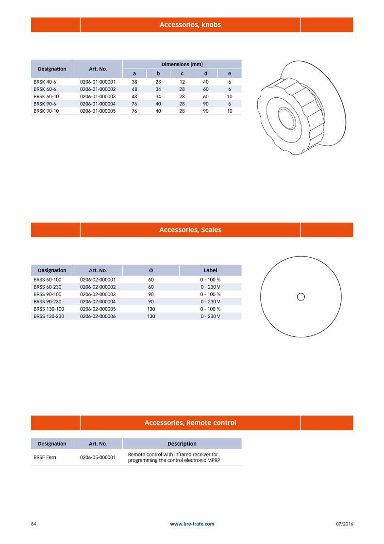
07/201684 www.bre-trafo.com
Designation Art. No.Dimensions [mm]
a b c d e
BRSK 40-6 0206-01-000001 38 28 12 40 6
BRSK 60-6 0206-01-000002 48 34 28 60 6
BRSK 60-10 0206-01-000003 48 34 28 60 10
BRSK 90-6 0206-01-000004 76 40 28 90 6BRSK 90-10 0206-01-000005 76 40 28 90 10
Designation Art. No. Ø Label
BRSS 60-100 0206-02-000001 60 0 - 100 %
BRSS 60-230 0206-02-000002 60 0 - 230 V
BRSS 90-100 0206-02-000003 90 0 - 100 %
BRSS 90-230 0206-02-000004 90 0 - 230 V
BRSS 130-100 0206-02-000005 130 0 - 100 %
BRSS 130-230 0206-02-000006 130 0 - 230 V
Accessories, knobs
Accessories, Scales
Designation Art. No. Description
BRSF Fern 0206-05-000001Remote control with infrared receiver for programming the control electronic MPRP
Accessories, Remote control

8507/2016 www.bre-trafo.com
Accessories, Variable speed drives
Designation Art. No. Description
BRSR AC 0206-03-000001 230V AC motor, control via buttons up, down
BRSR DC 0206-03-000002 24V DC motor, control via buttons up, down
BRSR DC-MPRP 0206-03-00000324V DC motor with control electronic, control via potentiometer or 0-10V signal
Accessories, Circuit boards
Designation Art. No. Description
BRSP MPRP 0206-04-000001 Control electronic for DC motors
BRSP RS232 0206-04-000002RS232 / 485 Interface for control electronic. For control via PC
BRSP ES 0206-04-000003Additional limiting switch board with potential free contracts.

07/201686 www.bre-trafo.com
BESKH 0,43 - 115 kVASingle-phase voltage stabilizer
General characteristics:• single-phase voltage stabilizer
• temperature class ta 40°C/B
• installed in a steel cabinet IP54
• main switch, fuse protection, bypass switch (optional)
• input voltage: AC 230V +…%
• output voltage: AC230 V +-1%
• other tolerances and power rates on request
Standards:EN 61558-2-13 Auto transformers
EN 61558-2-14 Variable transformers
Power Fuse[A]
Voltage tolerance
10% 15% 20% 25% 30%
0,43 kVA 2,0 --- --- --- --- 0804-10-000002
0,66 kVA 3,0 --- --- --- 0803-10-000003 0804-10-000003
0,90 kVA 4,0 --- --- 0802-10-000004 0803-10-000004 0804-10-000004
1,37 KVA 6,0 --- 0801-10-000006 0802-10-000006 0803-10-000006 0804-10-000006
2,30 kVA 10,0 0800-10-000010 0801-10-000010 0802-10-000010 0803-10-000010 0804-10-000010
2,97 kVA 13,0 0800-10-000013 0801-10-000013 0802-10-000013 0803-10-000013 0804-10-000013
3,67 kVA 16,0 0800-10-000016 0801-10-000016 0802-10-000016 0803-10-000016 0804-10-000016
4,60 kVA 20,0 0800-10-000020 0801-10-000020 0802-10-000020 0803-10-000020 0804-10-000020
5,73 kVA 25,0 0800-10-000025 0801-10-000025 0802-10-000025 0803-10-000025 0804-10-000025
7,34 kVA 32,0 0800-10-000032 0801-10-000032 0802-10-000032 0803-10-000032 0804-10-000032
9,20 kVA 40,0 0800-10-000040 0801-10-000040 0802-10-000040 0803-10-000040 0804-10-000040
11,5 kVA 50,0 0800-10-000050 0801-10-000050 0802-10-000050 0803-10-000050 0804-10-000050
14,5 kVA 63,0 0800-10-000063 0801-10-000063 0802-10-000063 0803-10-000063 0804-10-000063
18,4 kVA 80,0 0800-10-000080 0801-10-000080 0802-10-000080 0803-10-000080 0804-10-000080
23,0kVA 100,0 0800-10-000100 0801-10-000100 0802-10-000100 0803-10-000100 0804-10-000100
28,7 kVA 125,0 0800-10-000125 0801-10-000125 0802-10-000125 0803-10-000125 0804-10-000125
36,7 kVA 160,0 0800-10-000160 0801-10-000160 0802-10-000160 0803-10-000160 ---
46,0 kVA 200,0 0800-10-000200 0801-10-000200 0802-10-000200 --- ---
57,3 kVA 250,0 0800-10-000250 0801-10-000250 --- --- ---
72,3 kVA 315,0 0800-10-000315 0801-10-000315 --- --- ---
92,0 kVA 400,0 0800-10-000400 --- --- --- ---
115 kVA 500,0 0800-10-000500 --- --- --- ---

8707/2016 www.bre-trafo.com
BDSKH 1,3 - 345 kVAThree-phase voltage stabilizer
General characteristics:• single-phase voltage stabilizer
• temperature class ta 40°C/B
• installed in a steel cabinet IP54, RAL 7035
• main switch, fuse protection, bypass switch (optional)
• input voltage: 3AC 400V +…%
• output voltage: 3AC400 V +-1%
• other tolerances and power rates on request
Standards:EN 61558-2-13 Auto transformers
EN 61558-2-14 Variable transformers
Power Fuse[A]
Voltage tolerance
10% 15% 20% 25% 30%
1,3 kVA 2,0 --- --- --- --- 0814-10-000002
2,0 kVA 3,0 --- --- --- 0813-10-000003 0814-10-000003
2,7 kVA 4,0 --- --- 0812-10-000004 0813-10-000004 0814-10-000004
4,1 KVA 6,0 --- 0811-10-000006 0812-10-000006 0813-10-000006 0814-10-000006
6,9 kVA 10,0 0810-10-000010 0811-10-000010 0812-10-000010 0813-10-000010 0814-10-000010
8,9 kVA 13,0 0810-10-000013 0811-10-000013 0812-10-000013 0813-10-000013 0814-10-000013
11,0 kVA 16,0 0810-10-000016 0811-10-000016 0812-10-000016 0813-10-000016 0814-10-000016
13,8 kVA 20,0 0810-10-000020 0811-10-000020 0812-10-000020 0813-10-000020 0814-10-000020
17,2 kVA 25,0 0810-10-000025 0811-10-000025 0812-10-000025 0813-10-000025 0814-10-000025
22,0 kVA 32,0 0810-10-000032 0811-10-000032 0812-10-000032 0813-10-000032 0814-10-000032
27,6 kVA 40,0 0810-10-000040 0811-10-000040 0812-10-000040 0813-10-000040 0814-10-000040
34,5 kVA 50,0 0810-10-000050 0811-10-000050 0812-10-000050 0813-10-000050 0814-10-000050
43,4 kVA 63,0 0810-10-000063 0811-10-000063 0812-10-000063 0813-10-000063 0814-10-000063
55,2 kVA 80,0 0810-10-000080 0811-10-000080 0812-10-000080 0813-10-000080 0814-10-000080
69,0 kVA 100,0 0810-10-000100 0811-10-000100 0812-10-000100 0813-10-000100 0814-10-000100
86,2 kVA 125,0 0810-10-000125 0811-10-000125 0812-10-000125 0813-10-000125 0814-10-000125
110 kVA 160,0 0810-10-000160 0811-10-000160 0812-10-000160 0813-10-000160 ---
138 kVA 200,0 0810-10-000200 0811-10-000200 0812-10-000200 --- ---
172 kVA 250,0 0810-10-000250 0811-10-000250 --- --- ---
217 kVA 315,0 0810-10-000315 0811-10-000315 --- --- ---
276 kVA 400,0 0810-10-000400 --- --- --- ---
345 kVA 500,0 0810-10-000500 --- --- --- ---

07/201688 www.bre-trafo.com
Notes
8907/2016 www.bre-trafo.com
BENT Single-phase power supplies .............................................................................................................................. 91 BDNTS Three-phase power supplies, standing ............................................................................................................... 92 BDNTL Three-phase power supplies, laid ....................................................................................................................... 93 D-IPS-C Controllable power supply for TS35 top hat rail , primary-switched ................................................................... 94 D-IPS-BM DC UPS ................................................................................................................................................................ 95 MDR/SDR Single-phase power supply, primary switched (low cost) ................................................................................... 96 WDR Dual-phase power supply, primary switched (low cost) ...................................................................................... 98 DRH/DRT Three-phase power supply, primary switched (low cost) .................................................................................... 99 DR-RDN Redundancy module ......................................................................................................................................... 100 DR-UPS DC UPS, (low cost) ............................................................................................................................................. 100
5 | POWER SUPPLIES

07/201690 www.bre-trafo.com
Notes

9107/2016 www.bre-trafo.com
BENT 1 - 15 ASingle-phase power supplies
General characteristics:• single-phase power supply without capacitor
• input voltage: AC 220/230/240 V
• output voltage: DC 24V
• ripple 48 % (smaller available on request)
• voltage adjustments by +-5% tappings at input side
• open design for stationary installation
• back of hand and finger contact protected terminals, according
to DGUV rule 3
• IPxxP, insulation class B, max ambient temperature
40°C (ta 40°C/B)
• other tolerances and power rates on request
Standards:EN 61558-2-6 Safety transformer
Model Art-No. Current [A] Size Copper
[kg] Total [kg]
Dimensions [mm]
B T H a b Screw
BENT 1 0900-10-000001 1 EI 66/34 0,20 1,00 66 78 90 50 52 M4
BENT 3 0900-10-000003 3 EI 84/43 0,35 2,40 85 82 100 64 61 M4
BENT 5 0900-10-000005 5 EI 96/45 0,63 3,30 100 88 150 84 70 M5
BENT 8 0900-10-000008 8 EI 105/60 0,65 5,50 105 104 150 84 85 M5
BENT 10 0900-10-000010 10 EI 120/41 1,20 5,50 120 90 160 90 70 M5
BENT 15 0900-10-000015 15 EI 120/73 1,50 7,60 120 120 160 90 102 M5

07/201692 www.bre-trafo.com
BDNTS 5 - 90 AThree-phase power supplies, standing
General characteristics:• three-phase power supply without capacitor, standing
• input voltage: 3AC 380/400/420 V
• output voltage: DC 24V
• ripple 4,8 % (without capacitor, B6 connection)
• ripple 1 % (without capacitor, B12 connection)
• high ambient temperature possible, because no capacitor installed
• voltage adjustments by +-5% tappings at input side
• open design for stationary installation
• back of hand and finger contact protected terminals, according
to DGUV rule 3
• IPxxB, insulation class B, max ambient temperature
40°C (ta 40°C/B)
• other tolerances and power rates on request
B6 circuit, 4,8% ripple
Standards:EN 61558-2-6 Safety transformer
Model Art-No. Current [A] Size Copper
[kg] Total [kg]
Dimensions [mm]
B T H a b Screw
BDNTS 6-5 0901-10-000005 5 3UI 60/31 0,70 3,00 119 67 175 90 49 M4
BDNTS 6-7,5 0901-10-0007,5 7,5 3UI 75/26 1,30 4,40 150 67 200 113 49 M5
BDNTS 6-10 0901-10-000010 10 3UI 75/26 1,50 4,60 150 67 200 113 49 M5
BDNTS 6-15 0901-10-000015 15 3UI 75/41 1,80 6,80 150 87 200 113 64 M5
BDNTS 6-20 0901-10-000020 20 3UI 90/31 2,70 8,30 178 131 167 136 57 M6
BDNTS 6-25 0901-10-000025 25 3UI 90/41 3,20 9,40 178 141 167 136 67 M6
BDNTS 6-30 0901-10-000030 30 3UI 90/51 3,40 10,5 178 151 167 136 77 M6
BDNTS 6-40 0901-10-000040 40 3UI 120/41 5,00 17,0 240 200 217 185 71 M8
BDNTS 6-50 0901-10-000050 50 3UI 120/51 5,30 19,0 240 210 217 185 81 M8
BDNTS 6-60 0901-10-000060 60 3UI 120/61 5,80 23,0 240 206 270 185 91 M8
BDNTS 6-80 0901-10-000080 80 3UI 120/66 7,50 27,0 240 255 281 185 96 M8
BDNTS 6-90 0901-10-000090 90 3UI 120/75 8,50 29,0 240 262 281 185 105 M8
B12 circuit, 1% ripple
Model Art-No. Current [A] Size Copper
[kg] Total [kg]
Dimensions [mm]
B T H a b Screw
BDNTS 12-5 0902-10-000005 5 3UI 60/31 0,70 3,00 119 67 175 90 49 M4
BDNTS 12-7,5 0902-10-0007,5 7,5 3UI 75/26 1,30 4,40 150 67 200 113 49 M5
BDNTS 12-10 0902-10-000010 10 3UI 75/26 1,50 4,60 150 67 200 113 49 M5
BDNTS 12-15 0902-10-000015 15 3UI 75/41 1,80 6,80 150 87 200 113 64 M5
BDNTS 12-20 0902-10-000020 20 3UI 90/31 2,70 8,30 178 131 167 136 57 M6
BDNTS 12-25 0902-10-000025 25 3UI 90/41 3,20 9,40 178 141 167 136 67 M6
BDNTS 12-30 0902-10-000030 30 3UI 90/51 3,40 10,5 178 151 167 136 77 M6
BDNTS 12-40 0902-10-000040 40 3UI 120/41 5,00 17,0 240 200 217 185 71 M8
BDNTS 12-50 0902-10-000050 50 3UI 120/51 5,30 19,0 240 210 217 185 81 M8
BDNTS 12-60 0902-10-000060 60 3UI 120/61 5,80 23,0 240 206 270 185 91 M8
BDNTS 12-80 0902-10-000080 80 3UI 120/66 7,50 27,0 240 255 281 185 96 M8
BDNTS 12-90 0902-10-000090 90 3UI 120/75 8,50 29,0 240 262 281 185 105 M8
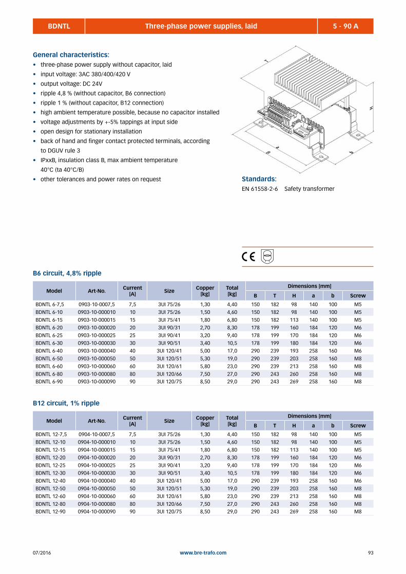
9307/2016 www.bre-trafo.com
BDNTL 5 - 90 AThree-phase power supplies, laid
General characteristics:• three-phase power supply without capacitor, laid
• input voltage: 3AC 380/400/420 V
• output voltage: DC 24V
• ripple 4,8 % (without capacitor, B6 connection)
• ripple 1 % (without capacitor, B12 connection)
• high ambient temperature possible, because no capacitor installed
• voltage adjustments by +-5% tappings at input side
• open design for stationary installation
• back of hand and finger contact protected terminals, according
to DGUV rule 3
• IPxxB, insulation class B, max ambient temperature
40°C (ta 40°C/B)
• other tolerances and power rates on request Standards:EN 61558-2-6 Safety transformer
B6 circuit, 4,8% ripple
B12 circuit, 1% ripple
Model Art-No. Current [A] Size Copper
[kg] Total [kg]
Dimensions [mm]
B T H a b Screw
BDNTL 12-7,5 0904-10-0007,5 7,5 3UI 75/26 1,30 4,40 150 182 98 140 100 M5
BDNTL 12-10 0904-10-000010 10 3UI 75/26 1,50 4,60 150 182 98 140 100 M5
BDNTL 12-15 0904-10-000015 15 3UI 75/41 1,80 6,80 150 182 113 140 100 M5
BDNTL 12-20 0904-10-000020 20 3UI 90/31 2,70 8,30 178 199 160 184 120 M6
BDNTL 12-25 0904-10-000025 25 3UI 90/41 3,20 9,40 178 199 170 184 120 M6
BDNTL 12-30 0904-10-000030 30 3UI 90/51 3,40 10,5 178 199 180 184 120 M6
BDNTL 12-40 0904-10-000040 40 3UI 120/41 5,00 17,0 290 239 193 258 160 M6
BDNTL 12-50 0904-10-000050 50 3UI 120/51 5,30 19,0 290 239 203 258 160 M8
BDNTL 12-60 0904-10-000060 60 3UI 120/61 5,80 23,0 290 239 213 258 160 M8
BDNTL 12-80 0904-10-000080 80 3UI 120/66 7,50 27,0 290 243 260 258 160 M8BDNTL 12-90 0904-10-000090 90 3UI 120/75 8,50 29,0 290 243 269 258 160 M8
Model Art-No. Current [A] Size Copper
[kg] Total [kg]
Dimensions [mm]
B T H a b Screw
BDNTL 6-7,5 0903-10-0007,5 7,5 3UI 75/26 1,30 4,40 150 182 98 140 100 M5
BDNTL 6-10 0903-10-000010 10 3UI 75/26 1,50 4,60 150 182 98 140 100 M5
BDNTL 6-15 0903-10-000015 15 3UI 75/41 1,80 6,80 150 182 113 140 100 M5
BDNTL 6-20 0903-10-000020 20 3UI 90/31 2,70 8,30 178 199 160 184 120 M6
BDNTL 6-25 0903-10-000025 25 3UI 90/41 3,20 9,40 178 199 170 184 120 M6
BDNTL 6-30 0903-10-000030 30 3UI 90/51 3,40 10,5 178 199 180 184 120 M6
BDNTL 6-40 0903-10-000040 40 3UI 120/41 5,00 17,0 290 239 193 258 160 M6
BDNTL 6-50 0903-10-000050 50 3UI 120/51 5,30 19,0 290 239 203 258 160 M8
BDNTL 6-60 0903-10-000060 60 3UI 120/61 5,80 23,0 290 239 213 258 160 M8
BDNTL 6-80 0903-10-000080 80 3UI 120/66 7,50 27,0 290 243 260 258 160 M8BDNTL 6-90 0903-10-000090 90 3UI 120/75 8,50 29,0 290 243 269 258 160 M8

07/201694 www.bre-trafo.com
D-IPS-C 250 - 1.000 WControlable power supply for TS35 top hat rail
General characteristics:• power input circuit regulated digitally
• low standby consumption
• no starting inrush current
• coated assemblies (additional protection against dirt
and humidity)
• especially high transient strength
• extremely high overload reserve
• efficiency factor up to 94%
• active PFC
• isolated relay contact
• controllable output variables (U/I/P)
• analog and digital interface
• 12V/48V available on request Standards:
EN 60950-1 safety of information technology
equipment
EN 61000-3-2 electromagnetic compatibility
(EMV), limits for harmonic
currents
EN 61000-6-2 electromagnetic compatibility
(EMV), interference immunity of
manufactoring locations
EN 61204-3 low voltage power supplies with
direct current
EN 55011 industrial, scientific and medical
Class B devices
Model Art-No. Input [VAC]
Output [VDC]
Power[W]
Weight [kg]
Dimensions [mm]
B T H
D-IPS 250C-24 0281-01-100250 100-240 0-30 250 1,20 80 130 139
D-IPS 500C-24 0281-01-100500 100-240 0-30 500 1,45 80 130 139
D-IPS 1000C-24 0281-01-101000 100-240 0-30 1000 3,80 260 130 139
D-IPS 1000/3-C-24 0281-01-301000 3AC 380-500 0-30 1000 3,80 260 130 139
Model Art-No. Input [VAC]
Output [VDC]
Power[W]
Weight [kg]
Dimensions [mm]
B T H
D-IPS 250C-60 0281-02-100250 100-240 0-65 250 1,20 80 130 139

9507/2016 www.bre-trafo.com
Standards:EN 60950 information technology
equipment
EN 55011 industrial, scientific and medical
Class B devices
EN 6100-3-2 electromagnetic compatibility
(EMV), limits for harmonic
currents
EN 6100-6-2 electromagnetic compatibility
(EMV), interference immunity of
manufactoring locations
EN 61204-3 low voltage power supplies with
direct current
D-IPS-BM 150 - 1000 WUninteruptible power supply (DC UPS)
General characteristics:• max battery charging current adjustable
• deep discharge protection
• electronical battery short circuit proof
• RS232 interface
• signalling via LED‘s , relays, and digital I / O
• fault diagnostic (battery temperature, aging, cable break etc.
• for all current lead acid batteries (standard, AGM,Gel,Reinblei)
• thermal battery management including cylical monitoring
• additional data für D-IPS-IBM, look at construction series
D-IPS-BM (ACS charging method)
Model Art.-No. Input [VDC]
Output [VDC]
Power[W]
Weight [kg]
Dimensions [mm]
B T H
D-IPS-BM24-20 0283-01-000020 24 22-30 500 0,60 60 130 139
D-IPS-IBM (ACS charging method with integrated power supply)
Model Art.-No. Input [VAC]
Output [VDC]
Power[W]
Weight [kg]
Dimensions [mm]
B T H
D-IPS-IBM150-24 0283-03-000150 100-240 20-30 150 1,30 98 130 139
D-IPS-IBM250-24 0283-03-000250 100-240 20-30 250 1,60 119 130 139D-IPS-IBM500-24 0283-03-000500 100-240 20-30 500 1,90 119 130 139

07/201696 www.bre-trafo.com
Standards:EN 60950-1
EN 55022
EN 61000-3-2, 3
EN 61000-4-2,3,4,5,6,8,11
EN 61204-3
EN 61000-6-2
UL 508
MDR/SDR 10 - 960 WSingle-phase power supply, primary switched, low cost
General characteristics:• protection against: short circuit, overload, over voltage
• power on LED
• active PFC 100W
• potential free contact for DC-OK
• convection cooling
• Output voltage adjustable
C US
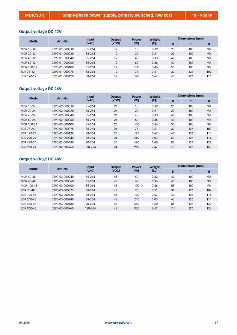
9707/2016 www.bre-trafo.com
MDR/SDR 10 - 960 WSingle-phase power supply, primary switched, low cost
Output voltage DC 12V
Model Art.-No. Input [VAC]
Output [VDC]
Power[W]
Weight [kg]
Dimensions [mm]
B T H
MDR 10-12 0290-01-000010 85-264 12 10 0,19 23 100 90
MDR 20-12 0290-01-000020 85-264 12 20 0,21 23 100 90MDR 40-12 0290-01-000040 85-264 12 40 0,33 40 100 90
MDR 60-12 0290-01-000060 85-264 12 60 0,36 40 100 90
MDR 100-12 0290-01-000100 85-264 12 100 0,46 55 100 90
SDR 75-12 0290-01-000075 88-264 12 75 0,51 32 126 102
SDR 120-12 0290-01-000120 88-264 12 120 0,67 40 126 114
Output voltage DC 24V
Model Art.-No. Input [VAC]
Output [VDC]
Power[W]
Weight [kg]
Dimensions [mm]
B T H
MDR 10-24 0290-02-000010 85-264 24 10 0,19 23 100 90
MDR 20-24 0290-02-000020 85-264 24 20 0,21 23 100 90MDR 40-24 0290-02-000040 85-264 24 40 0,33 40 100 90
MDR 60-24 0290-02-000060 85-264 24 60 0,36 40 100 90
MDR 100-24 0290-02-000100 85-264 24 100 0,46 55 100 90
SDR 75-24 0290-02-000075 88-264 24 75 0,51 32 126 102
SDR 120-24 0290-02-000120 88-264 24 120 0,67 40 126 114
SDR 240-24 0290-02-000240 88-264 24 240 1,03 63 126 114
SDR 480-24 0290-02-000480 90-264 24 480 1,60 86 126 129
SDR 960-24 0290-02-000960 180-264 24 960 2,47 110 126 150
Output voltage DC 48V
Model Art.-No. Input [VAC]
Output [VDC]
Power[W]
Weight [kg]
Dimensions [mm]
B T H
MDR 40-48 0290-03-000040 85-264 48 40 0,33 40 100 90
MDR 60-48 0290-03-000060 85-264 48 60 0,36 40 100 90MDR 100-48 0290-03-000100 85-264 48 100 0,46 55 100 90
SDR 75-48 0290-03-000075 88-264 48 75 0,51 32 126 102
SDR 120-48 0290-03-000120 88-264 48 120 0,67 40 126 114
SDR 240-48 0290-03-000240 88-264 48 240 1,03 63 126 114
SDR 480-48 0290-03-000480 90-264 48 480 1,60 86 126 129
SDR 960-48 0290-03-000960 180-264 48 960 2,47 110 126 150

07/201698 www.bre-trafo.com
WDR 120 - 480 WTwo-phase power supply, low cost
General characteristics:• protection against: short circuit, overload, over voltage, over
temperature
• power on LED
• active PFC 100W
• potential free contact for DC-OK
• convection cooling
• Output voltage adjustable
Standards:EN 60950-1
EN 55022
EN 61000-3-2, 3
EN 61000-4-2,3,4,5,6,8,11
EN 61204-3
EN 61000-6-2
UL 508
Output voltage DC 12V
Model Art.-No. Input [VAC]
Output [VDC]
Power[W]
Weight [kg]
Dimensions [mm]
B T H
WDR 120-12 0291-01-000120 180-550 12 120 0,70 40 114 126
Output voltage DC 24V
Model Art.-No. Input [VAC]
Output [VDC]
Power[W]
Weight [kg]
Dimensions [mm]
B T H
WDR 120-24 0291-02-000120 180-550 24 120 0,70 40 114 126
WDR 240-24 0291-02-000240 180-550 24 240 1,15 63 114 126WDR 480-24 0291-02-000480 180-550 24 480 1,90 86 129 126
Output voltage DC 48V
Model Art.-No. Input [VAC]
Output [VDC]
Power[W]
Weight [kg]
Dimensions [mm]
B T H
WDR 120-48 0291-03-000120 180-550 48 120 0,70 40 114 126
WDR 240-48 0291-03-000240 180-550 48 240 1,15 63 114 126WDR 480-48 0291-03-000480 180-550 48 480 1,90 86 129 126
C US

9907/2016 www.bre-trafo.com
DRH/DRT 120 - 480 WThree-phase power supply, low cost
General characteristics:• protection against: short circuit, overload, over voltage, over
temperature
• power on LED
• potential free contact for DC-OK
• convection cooling
• Output voltage adjustable
Standards:EN 60950-1
EN 55022
EN 61000-3-2, 3
EN 61000-4-2,3,4,5,6,8,11
EN 61204-3
EN 61000-6-2
UL 508
Output voltage DC 24V
Model Art.-No. Input [VAC]
Output [VDC]
Power[W]
Weight [kg]
Dimensions [mm]
B T H
DRH 120-24 0292-01-000120 3AC 340 -550 24 120 0,80 66 100 126
DRT 240-24 0292-01-000240 3AC 340 -550 24 240 1,40 126 100 126DRT 480-24 0292-01-000480 3AC 340 -550 24 480 2,70 227 100 126
DRT 960-24 0292-01-000960 3AC 340 -550 24 960 3,60 276 100 126
Output voltage DC 48V
Model Art.-No. Input [VAC]
Output [VDC]
Power[W]
Weight [kg]
Dimensions [mm]
B T H
DRH 120-48 0292-02-000120 3AC 340 -550 48 120 0,80 66 100 126
DRH 240-48 0292-02-000240 3AC 340 -550 48 240 1,40 126 100 126DRH 480-48 0292-02-000480 3AC 340 -550 48 480 2,70 227 100 126
DRH 960-48 0292-02-000960 3AC 340 -550 48 960 3,60 276 100 126
C US
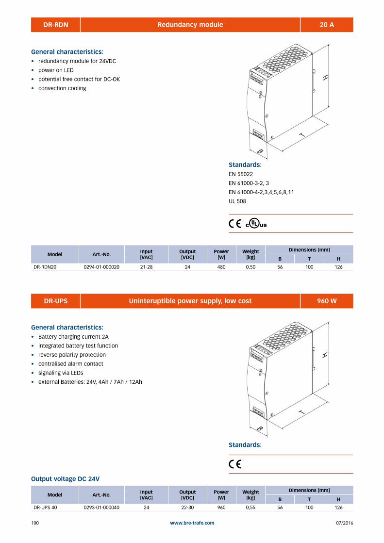
07/2016100 www.bre-trafo.com
DR-RDN 20 ARedundancy module
General characteristics:• redundancy module for 24VDC
• power on LED
• potential free contact for DC-OK
• convection cooling
Standards:EN 55022
EN 61000-3-2, 3
EN 61000-4-2,3,4,5,6,8,11
UL 508
Model Art.-No. Input [VAC]
Output [VDC]
Power[W]
Weight [kg]
Dimensions [mm]
B T H
DR-RDN20 0294-01-000020 21-28 24 480 0,50 56 100 126
C US
DR-UPS 960 WUninteruptible power supply, low cost
General characteristics:• Battery charging current 2A
• integrated battery test function
• reverse polarity protection
• centralised alarm contact
• signaling via LEDs
• external Batteries: 24V, 4Ah / 7Ah / 12Ah
Standards:
Output voltage DC 24V
Model Art.-No. Input [VAC]
Output [VDC]
Power[W]
Weight [kg]
Dimensions [mm]
B T H
DR-UPS 40 0293-01-000040 24 22-30 960 0,55 56 100 126

10107/2016 www.bre-trafo.com
BG Standing enclosures .......................................................................................................................................... 104 BG Wall mounted enclosures .................................................................................................................................. 105 BG Enclosure of glass fibre reinforced plastic ........................................................................................................ 106 BBG Assembly enclosure .......................................................................................................................................... 107 BBG Cube enclosure ................................................................................................................................................. 108 BSS Control cabinet (Rittal) ...................................................................................................................................... 109 Accessories, cable glands ................................................................................................................................. 110 Accessories, filter fan ........................................................................................................................................ 110 Accessories, floor socket .................................................................................................................................. 111 Accessories, Cabinet roles ................................................................................................................................ 111
6 | ENCLOSURES AND ACCESSORIES
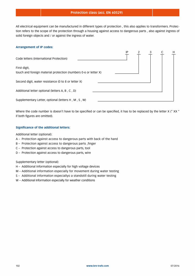
07/2016102 www.bre-trafo.com
Protection class (acc. EN 60529)
All electrical equipment can be manufactured in different types of protection , this also applies to transformers. Protec-
tion refers to the scope of the protection through a housing against access to dangerous parts , also against ingress of
solid foreign objects and / or against the ingress of water.
Arrangement of IP codes:
Code letters (International Protection)
First digit,
touch and foreign material protection (numbers 0-6 or letter X)
Second digit, water resistance (0 to 8 or letter X)
Additional letter optional (letters A, B , C , D)
Supplementary Letter, optional (letters H , M , S , W)
Where the code number is doesn’t have to be specified or can be specified, it has to be replaced by the letter X (“ XX “
if both figures are omitted).
Significance of the additional letters:
Additional letter (optional):
A – Protection against access to dangerous parts with back of the hand
B – Protection against access to dangerous parts ,finger
C – Protection against access to dangerous parts, tool
D – Protection against access to dangerous parts, wire
Supplementary letter (optional):
H – Additional Information especially for high voltage devices
M – Additional information especially for movement during water testing
S – Additional information especiallyo a standstill during water testing
W – Additional Information especially for weather conditions
IP 2 3 C H

10307/2016 www.bre-trafo.com
Meaning of the digits
Contact and foreign body protection (1st digit) Water protection (2nd digit)
IP 0 __ not protected
IP 1 __ protected against
solid objects greater
than 50 mm
IP 2 __ protected against
solid objects greater
than 12,5 mm
IP 3 __ protected against
solid objects greater
than 2,5 mm
IP 4 __ protected against
solid objects greater
than 1 mm
IP 5 __ dustproof
IP 6 __ dustproof
IP __ 0 not protected
IP __ 1 protected against dripping water
IP __ 2 protected against water drops,
when the enclosure is
tilted up to 15°
IP __ 3 protected against spraywater
IP __ 4 splashproof
IP __ 5 protected against water jets
IP __ 6 protected against powerful
water jets
IP __ 7 protected from the effects during
temporary submersion in water
IP __ 8 protected against the effects if
continual submersion in water
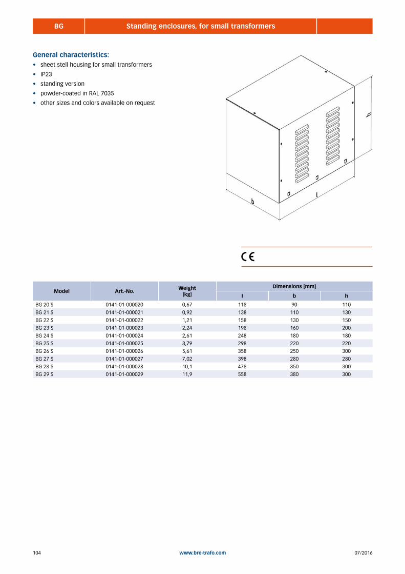
07/2016104 www.bre-trafo.com
BG Standing enclosures, for small transformers
General characteristics:• sheet stell housing for small transformers
• IP23
• standing version
• powder-coated in RAL 7035
• other sizes and colors available on request
Model Art.-No. Weight [kg]
Dimensions [mm]
I b h
BG 20 S 0141-01-000020 0,67 118 90 110
BG 21 S 0141-01-000021 0,92 138 110 130
BG 22 S 0141-01-000022 1,21 158 130 150
BG 23 S 0141-01-000023 2,24 198 160 200
BG 24 S 0141-01-000024 2,61 248 180 180
BG 25 S 0141-01-000025 3,79 298 220 220
BG 26 S 0141-01-000026 5,61 358 250 300
BG 27 S 0141-01-000027 7,02 398 280 280
BG 28 S 0141-01-000028 10,1 478 350 300
BG 29 S 0141-01-000029 11,9 558 380 300
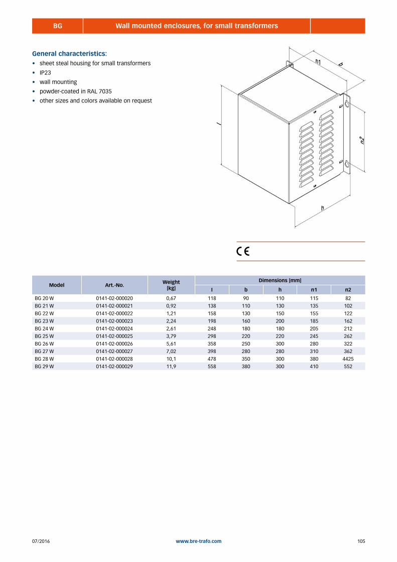
10507/2016 www.bre-trafo.com
BG Wall mounted enclosures, for small transformers
General characteristics:• sheet steal housing for small transformers
• IP23
• wall mounting
• powder-coated in RAL 7035
• other sizes and colors available on request
Model Art.-No. Weight [kg]
Dimensions [mm]
I b h n1 n2
BG 20 W 0141-02-000020 0,67 118 90 110 115 82
BG 21 W 0141-02-000021 0,92 138 110 130 135 102
BG 22 W 0141-02-000022 1,21 158 130 150 155 122
BG 23 W 0141-02-000023 2,24 198 160 200 185 162
BG 24 W 0141-02-000024 2,61 248 180 180 205 212
BG 25 W 0141-02-000025 3,79 298 220 220 245 262
BG 26 W 0141-02-000026 5,61 358 250 300 280 322
BG 27 W 0141-02-000027 7,02 398 280 280 310 362
BG 28 W 0141-02-000028 10,1 478 350 300 380 4425
BG 29 W 0141-02-000029 11,9 558 380 300 410 552
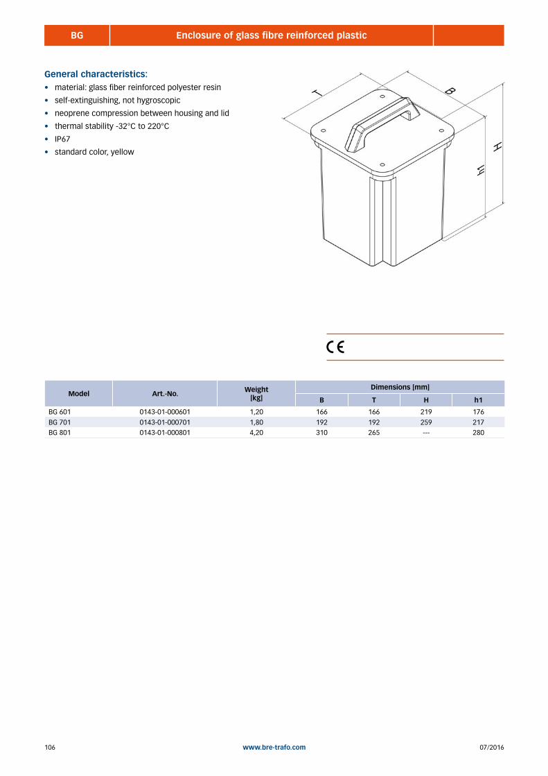
07/2016106 www.bre-trafo.com
BG Enclosure of glass fibre reinforced plastic
General characteristics:• material: glass fiber reinforced polyester resin
• self-extinguishing, not hygroscopic
• neoprene compression between housing and lid
• thermal stability -32°C to 220°C
• IP67
• standard color, yellow
Model Art.-No. Weight [kg]
Dimensions [mm]
B T H h1
BG 601 0143-01-000601 1,20 166 166 219 176
BG 701 0143-01-000701 1,80 192 192 259 217BG 801 0143-01-000801 4,20 310 265 --- 280

10707/2016 www.bre-trafo.com
BBG Assembly enclosures
General characteristics:• sheet steal housing for large transformers
• IP23 or IP54
• powder-coated in RAL 7035
• other sizes and colors available on request
BBG (IP23)
Model Art.-No. Weight [kg]
Dimensions [mm]
I l1 b b1 b2 h u1
BBG 110 0141-03-000110 22,0 550 460 490 400 500 495 460
BBG 120 0141-03-000120 27,0 610 520 540 450 550 575 510
BBG 130 0141-03-000130 19,5 610 520 430 340 440 435 400
BBG 140 0141-03-000140 25,0 670 580 490 400 500 495 460
BBG 150 0141-03-000150 31,0 770 680 540 450 550 575 510
BBG 160 0141-03-000160 42,0 855 765 620 530 630 635 590
BBG 170 0141-03-000170 58,0 1050 960 750 660 760 705 720
BBG 180 0141-03-000180 74,0 1150 1060 850 760 860 815 820
BBG 190 0141-03-000190 112 1340 1250 850 760 860 1265 820
BBG 210 0141-03-000210 39,0 750 660 580 490 590 605 550
BBG 220 0141-03-000220 56,0 840 750 490 400 500 815 460
BBG 230 0141-03-000230 48,0 940 850 640 550 650 745 610
BBG 240 0141-03-000240 73,0 1090 1000 590 500 600 1015 560
BBG 250 0141-03-000250 104 1290 1200 790 700 800 1115 760
BBG (IP54)
Model Art.-No. Weight [kg]
Dimensions [mm]
I l1 b b1 b2 h u1
BBG 110 0141-04-000110 23,0 550 460 490 400 500 495 460
BBG 120 0141-04-000120 28,0 610 520 540 450 550 575 510
BBG 130 0141-04-000130 20,0 610 520 430 340 440 435 400
BBG 140 0141-04-000140 26,0 670 580 490 400 500 495 460
BBG 150 0141-04-000150 32,0 770 680 540 450 550 575 510
BBG 160 0141-04-000160 44,0 855 765 620 530 630 635 590
BBG 170 0141-04-000170 60,0 1050 960 750 660 760 705 720
BBG 180 0141-04-000180 77,0 1150 1060 850 760 860 815 820
BBG 190 0141-04-000190 116 1340 1250 850 760 860 1265 820
BBG 210 0141-04-000210 41,0 750 660 580 490 590 605 550
BBG 220 0141-04-000220 58,0 840 750 490 400 500 815 460
BBG 230 0141-04-000230 50,0 940 850 640 550 650 745 610
BBG 240 0141-04-000240 76,0 1090 1000 590 500 600 1015 560
BBG 250 0141-04-000250 109 1290 1200 790 700 800 1115 760

07/2016108 www.bre-trafo.com
BBG Cube enclosures
General characteristics:• sheet steal housing for large transformers
• IP23
• powder-coated in RAL 7035
• other sizes and colors available on request
Model Art.-No. Weight [kg]
Dimensions [mm]
B T H h1
BBG 400 0141-05-000400 28,0 400 400 400 500
BBG 500 0141-05-000500 38,0 500 500 500 600BBG 650 0141-05-000600 60,0 650 650 650 750

10907/2016 www.bre-trafo.com
BSS Control cabinets (Rittal)
General characteristics:• control cabinet
• IP55 (NEMA12), without fan or installations
• powder-coated in RAL 7035
• including 100mm socket and sidewalls
• other sizes and colors available on request
Model Art.-No. IP Doors Weight [kg]
Dimensions [mm]
B H T a
BSS 5110 1000-10-005110 55 1 44,0 600 800 400 100
BSS 5111 1000-10-005111 55 1 54,0 600 1000 400 100BSS 5112 1000-10-005112 55 1 57,0 600 1200 300 100
BSS 5113 1000-10-005113 55 1 61,0 600 1200 400 100BSS 5114 1000-10-005114 55 1 62,0 800 1000 300 100
BSS 5115 1000-10-005115 55 1 66,0 800 1000 400 100
BSS 5116 1000-10-005116 55 1 70,0 800 1200 300 100
BSS 5117 1000-10-005117 55 1 76,0 800 1200 400 100
BSS 5118 1000-10-005118 55 2 75,0 1000 1000 300 100
BSS 5119 1000-10-005119 55 2 87,0 1000 1200 300 100
BSS 5120 1000-10-005120 55 2 91,0 1000 1200 400 100
BSS 5121 1000-10-005121 55 2 100 1000 1400 300 100
BSS 5122 1000-10-005122 55 2 105 1000 1400 400 100
BSS 5123 1000-10-005123 55 2 107 1200 1200 400 100
BSS 8615 1000-10-008615 55 1 100 600 1200 500 100
BSS 8815 1000-10-008815 55 1 117 800 1200 500 100
BSS 8215 1000-10-008215 55 2 165 1200 1200 500 100
BSS 8645 1000-10-008645 55 1 111 600 1400 500 100
BSS 8845 1000-10-008845 55 1 133 800 1400 500 100
BSS 8245 1000-10-008245 55 2 189 1200 1400 500 100
BSS 8665 1000-10-008665 55 1 125 600 1600 500 100
BSS 8865 1000-10-008865 55 1 128 800 1600 500 100
BSS 8265 1000-10-008265 55 2 184 1200 1600 500 100
BSS 8686 1000-10-008686 55 1 122 600 1800 600 100
BSS 8886 1000-10-008886 55 1 145 800 1800 600 100
BSS 8286 1000-10-008286 55 2 205 1200 1800 600 100
BSS 8606 1000-10-008606 55 1 129 600 2000 600 100
BSS 8806 1000-10-008806 55 1 156 800 2000 600 100
BSS 8006 1000-10-008006 55 2 186 1000 2000 600 100
BSS 8206 1000-10-008206 55 2 220 1200 2000 600 100
BSS 8608 1000-10-008608 55 1 136 600 2000 800 100
BSS 8808 1000-10-008808 55 1 162 800 2000 800 100
BSS 8208 1000-10-008208 55 2 228 1200 2000 800 100

07/2016110 www.bre-trafo.com
Accessories, Cable glands
General characteristics:• cable glands
• metric
• plastic or metal
• EMC cable gland on request
Plastic - PA
Model Art.-No. Sealing area[mm]
M12 PA 0190-02-000012 3 - 7
M16 PA 0190-02-000016 4,5 - 10M20 PA 0190-02-000020 6 - 13
M25 PA 0190-02-000025 9 - 17
M32 PA 0190-02-000032 18 - 25
M40 PA 0190-02-000040 16 - 28
M50 PA 0190-02-000050 21 - 35
M63 PA 0190-02-000063 34 - 48
Metal - FE
Model Art.-No. Sealing area[mm]
M12 FE 0190-01-000012 3 - 7
M16 FE 0190-01-000016 4,5 - 10M20 FE 0190-01-000020 6 - 13
M25 FE 0190-01-000025 9 - 17
M32 FE 0190-01-000032 18 - 25
M40 FE 0190-01-000040 16 - 28
M50 FE 0190-01-000050 21 - 35
M63 FE 0190-01-000063 34 - 48
Accessories, Filter fan
General characteristics:• filter fan and filter
• IP54 with filter mat
• 230 VAC 50/60 Hz
• 115 VAC oder 24 DC versions available on request
• EMC versions available on request
Filter fan
Austrittsfilter
The details of the amount of air relate to the particular use of a filter fan and the corresponding outlet filter.
Model Art.-No. Air flow[m³/h]
Dimensions [mm]
B H T
SK 3237.100 0140-04-003237 15 116,5 116,5 43
SK 3238.100 0140-04-003238 43 148,5 148,5 58,5SK 3239.100 0140-04-003239 98 204 204 90
SK 3240.100 0140-04-003240 138 255 255 107
SK 3241.100 0140-04-003241 183 255 255 107
SK 3243.100 0140-04-003243 440 323 323 118,5
SK 3244.100 0140-04-003244 544 323 323 130,5
Model Art.-No. Air flow[m³/h]
Dimensions [mm]
B H T
SK 3237.200 0140-05-003237 15 116,5 116,5 ---
SK 3238.200 0140-05-003238 43 148,5 148,5 ---SK 3239.200 0140-05-003239 98 204 204 ---
SK 3240.200 0140-05-003240 138 255 255 ---
SK 3243.200 0140-05-003243 440 323 323 ---

11107/2016 www.bre-trafo.com
Accessories, Socket
General characteristics:• heavy duty socket
• powder-coated in RAL 7035
• kit consisting 2 units
• other sizes and colors available on request
Model Art.-No. Weight[kg]
Dimensions [mm]
B T H
BZBS 100-400 0141-06-100400 6,80 50 400 100
BZBS 100-500 0141-06-100500 8,60 50 500 100BZBS 100-600 0141-06-100600 10,2 50 600 100
BZBS 100-800 0141-06-100800 13,6 50 800 100
BZBS 200-400 0141-06-200400 17,2 75 400 200
BZBS 200-500 0141-06-200500 21,6 75 500 200
BZBS 200-600 0141-06-200600 25,8 75 600 200
BZBS 200-800 0141-06-200800 34,4 75 800 200
Accessories, cabinet roles
General characteristics:• heavy duty cabinet roles
• casters or fixed casters for heavy loads
• other sizes an weights available on request
Model Art.-No. Capacity/role[kg]
Dimensions [mm]Covering Kind
B T H Ø
B-PO75R 0142-01-000001 200 85 100 100 75 PA Bock
L-PO75R-FI 0142-01-000002 200 85 100 100 75 PA LenkBH-GTH 100K-1 0142-01-000003 400 85 100 140 100 PU Bock
LH-GTH 100K-1-FI 0142-01-000004 400 85 100 140 100 PU Lenk
BH-GB 125K-1 0142-01-000005 500 85 100 165 125 PU Bock
LH-GB 125K-1-FI 0142-01-000006 500 85 100 165 125 PU Lenk

07/2016112 www.bre-trafo.com
Notes

11307/2016 www.bre-trafo.com
Main switch ....................................................................................................................................................... 114 Transformer protection switch .......................................................................................................................... 114 Motor protection switch ................................................................................................................................... 115 Circuit breaker .................................................................................................................................................. 115 Miniature circuit breakers ................................................................................................................................. 116 Fuses ................................................................................................................................................................. 117 Connection cable .............................................................................................................................................. 117 Panel meters ..................................................................................................................................................... 118 Socket/plug ....................................................................................................................................................... 118 BDESB Inrush current limiter ........................................................................................................................................ 120
7 | ELECTRICAL ACESSORIES

07/2016114 www.bre-trafo.com
20 - 250 AMain switch
4 - 25 ATransformer protection switch
General characteristics:• main switch, service switch
• central attachment or fasten front panel (depending on size)
• black version (main and service switch)
• red / yellow version (main switch with emergency stop)
• other currents and versions available on request
General characteristics:• transformer protection switch
• thermomagnetic actuator
• overload actuator adjustable
• top hat rail mounting
• other currents available on request
Model Art.-No. Current[A] Color Poles Voltage
[V]
Dimensions [mm]
B H T
HLT20/3ZM/Z33 0250-01-000001 20 schwarz 3 690 66 66 50
HLT40/3ZM/Z33 0250-01-000002 40 schwarz 3 690 66 66 50HLT63/3ZM/Z33 0250-01-000003 63 schwarz 3 690 66 66 74
HLT100/3E/Z33 0250-01-000004 100 schwarz 3 690 66 66 74
HLT180/3E/Z33 0250-01-000005 180 schwarz 3 690 94 94 93
HLT250/3E/Z33 0250-01-000006 250 schwarz 3 690 94 94 110
NLT20/3ZM/Z33 0250-02-000001 20 rot/gelb 3 690 66 66 50
NLT40/3ZM/Z33 0250-02-000002 40 rot/gelb 3 690 66 66 50
NLT63/3ZM/Z33 0250-02-000003 63 rot/gelb 3 690 66 66 74
NLT100/3E/Z33 0250-02-000004 100 rot/gelb 3 690 66 66 74
NLT180/3E/Z33 0250-02-000005 180 rot/gelb 3 690 94 94 93
NLT250/3E/Z33 0250-02-000006 250 rot/gelb 3 690 94 94 110
Model Art.-No. Current[A] Poles Voltage
[V]
Dimensions [mm]
B H T
PKZM 0-6,3-T 0234-01-000001 4 - 6,3 3 690 45 93 76
PKZM 0-10-T 0234-01-000002 6,3 - 10 3 690 45 93 76PKZM 0-12-T 0234-01-000003 8 - 12 3 690 45 93 76
PKZM 0-16-T 0234-01-000004 10 - 16 3 690 45 93 76
PKZM 0-20-T 0234-01-000005 16 - 20 3 690 45 93 76
PKZM 0-25-T 0234-01-000006 20 - 25 3 690 45 93 76

11507/2016 www.bre-trafo.com
4-65 A
50 - 300 A
Motor protection switch
Circuit breaker
General characteristics:• motor protection switch
• thermomagnetic actuator
• overload actuator adjustable
• top hat rail mounting
• other currents available on request
General characteristics:• power circuit breaker
• thermomagnetic actuator
• overload actuator adjustable
• short circuit release set
• switching capacity 25kA
• other sizes on request
Model Art.-No. Current[A] Poles Voltage
[V]
Dimensions [mm]
B H T
PKZM 0-6,3 0233-01-000001 4 - 6,3 3 690 45 93 76
PKZM 0-10 0233-01-000002 6,3 - 10 3 690 45 93 76PKZM 0-12 0233-01-000003 8 - 12 3 690 45 93 76
PKZM 0-16 0233-01-000004 10 - 16 3 690 45 93 76
PKZM 0-20 0233-01-000005 16 - 20 3 690 45 93 76
PKZM 0-25 0233-01-000006 20 - 25 3 690 45 93 76
PKZM 0-32 0233-01-000007 25 - 32 3 690 45 93 76
PKZM 4-40 0233-01-000008 32 - 40 3 690 55 140 160
PKZM 4-50 0233-01-000009 40 - 50 3 690 55 140 160
PKZM 4-58 0233-01-000010 50 - 58 3 690 55 140 160
PKZM 4-63 0233-01-000011 55 - 65 3 690 55 140 160
Model Art.-No. Current[A] Poles Voltage
[V]
Dimensions [mm]
B H T
NZMB1-A63 0232-02-000001 50 - 63 3 690 90 265 85
NZMB1-A80 0232-02-000002 63 - 80 3 690 90 265 85NZMB1-A100 0232-02-000003 80 - 100 3 690 90 265 85
NZMB1-A125 0232-02-000004 100 - 125 3 690 90 265 85
NZMB1-A160 0232-02-000005 125 - 160 3 690 90 265 85
NZMB2-A200 0232-02-000006 160 - 200 3 690 115 276 149
NZMB2-A250 0232-02-000007 200 - 250 3 690 115 276 149
NZMB2-A300 0232-02-000008 240 - 300 3 690 115 276 149
Model Art.-No. Color
NZM1-XTVDVR 0232-04-000001 rot/gelb
NZM2-XTVDVR 0232-04-000002 rot/gelbNZM1-XTVD 0232-04-000003 schwarz
NZM2-XTVD 0232-04-000004 schwarz
Door coupling rotary handles
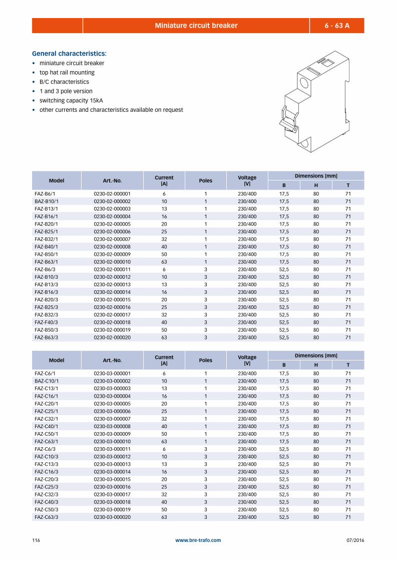
07/2016116 www.bre-trafo.com
6 - 63 AMiniature circuit breaker
General characteristics:• miniature circuit breaker
• top hat rail mounting
• B/C characteristics
• 1 and 3 pole version
• switching capacity 15kA
• other currents and characteristics available on request
Model Art.-No. Current[A] Poles Voltage
[V]
Dimensions [mm]
B H T
FAZ-B6/1 0230-02-000001 6 1 230/400 17,5 80 71
BAZ-B10/1 0230-02-000002 10 1 230/400 17,5 80 71FAZ-B13/1 0230-02-000003 13 1 230/400 17,5 80 71
FAZ-B16/1 0230-02-000004 16 1 230/400 17,5 80 71
FAZ-B20/1 0230-02-000005 20 1 230/400 17,5 80 71
FAZ-B25/1 0230-02-000006 25 1 230/400 17,5 80 71
FAZ-B32/1 0230-02-000007 32 1 230/400 17,5 80 71
FAZ-B40/1 0230-02-000008 40 1 230/400 17,5 80 71
FAZ-B50/1 0230-02-000009 50 1 230/400 17,5 80 71
FAZ-B63/1 0230-02-000010 63 1 230/400 17,5 80 71
FAZ-B6/3 0230-02-000011 6 3 230/400 52,5 80 71
FAZ-B10/3 0230-02-000012 10 3 230/400 52,5 80 71
FAZ-B13/3 0230-02-000013 13 3 230/400 52,5 80 71
FAZ-B16/3 0230-02-000014 16 3 230/400 52,5 80 71
FAZ-B20/3 0230-02-000015 20 3 230/400 52,5 80 71
FAZ-B25/3 0230-02-000016 25 3 230/400 52,5 80 71
FAZ-B32/3 0230-02-000017 32 3 230/400 52,5 80 71
FAZ-F40/3 0230-02-000018 40 3 230/400 52,5 80 71
FAZ-B50/3 0230-02-000019 50 3 230/400 52,5 80 71
FAZ-B63/3 0230-02-000020 63 3 230/400 52,5 80 71
Model Art.-No. Current[A] Poles Voltage
[V]
Dimensions [mm]
B H T
FAZ-C6/1 0230-03-000001 6 1 230/400 17,5 80 71
BAZ-C10/1 0230-03-000002 10 1 230/400 17,5 80 71FAZ-C13/1 0230-03-000003 13 1 230/400 17,5 80 71
FAZ-C16/1 0230-03-000004 16 1 230/400 17,5 80 71
FAZ-C20/1 0230-03-000005 20 1 230/400 17,5 80 71
FAZ-C25/1 0230-03-000006 25 1 230/400 17,5 80 71
FAZ-C32/1 0230-03-000007 32 1 230/400 17,5 80 71
FAZ-C40/1 0230-03-000008 40 1 230/400 17,5 80 71
FAZ-C50/1 0230-03-000009 50 1 230/400 17,5 80 71
FAZ-C63/1 0230-03-000010 63 1 230/400 17,5 80 71
FAZ-C6/3 0230-03-000011 6 3 230/400 52,5 80 71
FAZ-C10/3 0230-03-000012 10 3 230/400 52,5 80 71
FAZ-C13/3 0230-03-000013 13 3 230/400 52,5 80 71
FAZ-C16/3 0230-03-000014 16 3 230/400 52,5 80 71
FAZ-C20/3 0230-03-000015 20 3 230/400 52,5 80 71
FAZ-C25/3 0230-03-000016 25 3 230/400 52,5 80 71
FAZ-C32/3 0230-03-000017 32 3 230/400 52,5 80 71
FAZ-C40/3 0230-03-000018 40 3 230/400 52,5 80 71
FAZ-C50/3 0230-03-000019 50 3 230/400 52,5 80 71
FAZ-C63/3 0230-03-000020 63 3 230/400 52,5 80 71

11707/2016 www.bre-trafo.com
up to 1600 AFuses
Connection cables
General characteristics:• holder and fuses – glass tube 5x20mm
• holder and fuses – glass tube 6,3x32mm
• holder and fuses – D0
• holder and fuses – NH
General characteristics:• connection cable H07RN-F
• for average mechanical stresses
• halogen-free
• flame retardant
• other cable types , lengths and cross-sections on request
Model Art.-No. Current[A] Wires Voltage
[V]Length
[m]
H07RN-F 3G1,5 1100-10-000001 16 2 + PE 450/750 5
H07RN-F 3G2,5 1100-10-000002 25 2 + PE 450/750 5H07RN-F 5G1,5 1100-10-000003 16 4 + PE 450/750 5
H07RN-F 5G2,5 1100-10-000004 25 4 + PE 450/750 5
H07RN-F 5G4 1100-10-000005 32 4 + PE 450/750 5
H07RN-F 5G6 1100-10-000006 40 4 + PE 450/750 5
H07RN-F 5G10 1100-10-000007 50 4 + PE 450/750 5
H07RN-F 5G16 1100-10-000008 63 4 + PE 450/750 5
H07RN-F 5G25 1100-10-000009 80 4 + PE 450/750 5
H07RN-F 5G35 1100-10-000010 100 4 + PE 450/750 5
Model Art.-No. Current[A] Poles Voltage
[V]
Dimensions [mm]
B H T
BZSS 5x20 0234-04-000001 16 1 500 6,2 61,5 62,5
BZSS 6,3x32 0234-05-000001 20 1 500 8,2 76,5 69BZSS D02-1 0231-03-000001 63 1 500 27 80 55
BZSS D02-3 0231-03-000002 63 3 500 81 80 55
BZSS NH00 0235-01-000001 160 3 690 106 200 83
BZSS NH1 0235-01-000002 250 3 690 184 243 112
BZSS NH2 0235-01-000003 400 3 690 210 288 120
BZSS NH3 0235-01-000004 630 3 690 256 300 143
BZSS NH4a 0235-01-000005 1600 3 690 378 340 265

07/2016118 www.bre-trafo.com
Panel meters
General characteristics:• analog panel meters
• 96mm
• digital measurement devices, multifunctional power meter, other sizes
or values available on request
Model Art.-No. AC/DC Current[A]
Voltage[V]
Converter/shunt
Dimensions [mm]
H T
EQB96-10V 0240-03-000001 AC --- 10 --- 96 96
EQB96-60V 0240-03-000002 AC --- 60 --- 96 96EQB96-100V 0240-03-000003 AC --- 100 --- 96 96
EQB96-250V 0240-03-000004 AC --- 250 --- 96 96
EQB96-300V 0240-03-000005 AC --- 300 --- 96 96
EQB96-500V 0240-03-000006 AC --- 500 --- 96 96
EQB96-600V 0240-03-000007 AC --- 600 --- 96 96
DQB96-10V 0240-04-000001 DC --- 10 --- 96 96
DQB96-25V 0240-04-000002 DC --- 25 --- 96 96
DQB96-40V 0240-04-000003 DC --- 40 --- 96 96
DQB96-60V 0240-04-000004 DC --- 60 --- 96 96
DQB96-500V 0240-04-000005 DC --- 500 --- 96 96
EQB96-10 0240-01-000001 AC 10 / 20 --- --- 96 96
EQB96-15 0240-01-000002 AC 15 / 30 --- --- 96 96
EQB96-25 0240-01-000003 AC 25 / 50 --- --- 96 96
EQB96-40 0240-01-000004 AC 40 / 80 --- --- 96 96
EQB96-60 0240-01-000005 AC 60 / 120 --- --- 96 96
EQB96-100 0240-01-000006 AC 100 / 200 --- 1A 96 96
EQB96-200 0240-01-000007 AC 200 / 400 --- 1A 96 96
DQB96-10 0240-02-000001 DC 10 --- 60mV 96 96
DQB96-15 0240-02-000002 DC 15 --- 60mV 96 96
DQB96-25 0240-02-000003 DC 25 --- 60mV 96 96
DQB96-40 0240-02-000004 DC 40 --- 60mV 96 96
DQB96-60 0240-02-000005 DC 60 --- 60mV 96 96
DQB96-100 0240-02-000006 DC 100 --- 60mV 96 96
DQB96-200 0240-02-000007 DC 200 --- 60mV 96 96

11907/2016 www.bre-trafo.com
Sockets/plugs
General characteristics:• built in socket
• plugs
• various versions
• other voltages and versions available on request
Model Art.-No. Current[A] Color Poles Voltage
[V] PE
Dose CEE 400V 16A 0251-01-000001 16 rot 5 400 6h
Dose CEE 400V 32A 0251-01-000002 32 rot 5 400 6hDose CEE 400V 63A 0251-01-000003 63 rot 5 400 6h
Dose CEE 230V 16A 0251-01-000004 16 blau 5 230 9h
Dose CEE 230V 32A 0251-01-000005 32 blau 5 230 9h
Dose CEE 230V 63A 0251-01-000006 63 blau 5 230 9h
Dose CEE 500V 16A 0251-01-000007 16 schwarz 5 500 7h
Dose CEE 500V 32A 0251-01-000008 32 schwarz 5 500 7h
Dose CEE 500V 63A 0251-01-000009 63 schwarz 5 500 7h
Dose Schuko 230V 16A 0251-01-000010 16 blau 3 230 ---
Dose US 115V 15A 0251-01-000011 15 blau 3 115 ---
Model Art.-No. Current[A] Color Poles Voltage
[V] PE
Stecker CEE 400V 16A 0252-01-000001 16 rot 5 400 6h
Stecker CEE 400V 32A 0252-01-000002 32 rot 5 400 6hStecker CEE 400V 63A 0252-01-000003 63 rot 5 400 6h
Stecker CEE 230V 16A 0252-01-000004 16 blau 5 230 9h
Stecker CEE 230V 32A 0252-01-000005 32 blau 5 230 9h
Stecker CEE 230V 63A 0252-01-000006 63 blau 5 230 9h
Stecker CEE 500V 16A 0252-01-000007 16 schwarz 5 500 7h
Stecker CEE 500V 32A 0252-01-000008 32 schwarz 5 500 7h
Stecker CEE 500V 63A 0252-01-000009 63 schwarz 5 500 7h
Stecker Schuko 230V 16A 0252-01-000010 16 blau 3 230 ---
Stecker US 115V 15A 0252-01-000011 15 blau 3 115 ---
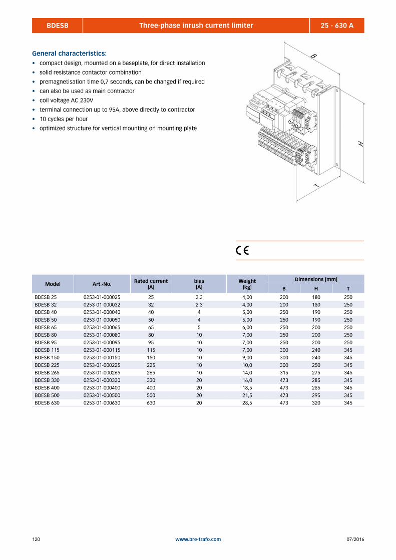
07/2016120 www.bre-trafo.com
BDESB 25 - 630 AThree-phase inrush current limiter
General characteristics:• compact design, mounted on a baseplate, for direct installation
• solid resistance contactor combination
• premagnetisation time 0,7 seconds, can be changed if required
• can also be used as main contractor
• coil voltage AC 230V
• terminal connection up to 95A, above directly to contractor
• 10 cycles per hour
• optimized structure for vertical mounting on mounting plate
Model Art.-No. Rated current[A]
bias [A]
Weight[kg]
Dimensions [mm]
B H T
BDESB 25 0253-01-000025 25 2,3 4,00 200 180 250
BDESB 32 0253-01-000032 32 2,3 4,00 200 180 250BDESB 40 0253-01-000040 40 4 5,00 250 190 250
BDESB 50 0253-01-000050 50 4 5,00 250 190 250
BDESB 65 0253-01-000065 65 5 6,00 250 200 250
BDESB 80 0253-01-000080 80 10 7,00 250 200 250
BDESB 95 0253-01-000095 95 10 7,00 250 200 250
BDESB 115 0253-01-000115 115 10 7,00 300 240 345
BDESB 150 0253-01-000150 150 10 9,00 300 240 345
BDESB 225 0253-01-000225 225 10 10,0 300 250 345
BDESB 265 0253-01-000265 265 10 14,0 315 275 345
BDESB 330 0253-01-000330 330 20 16,0 473 285 345
BDESB 400 0253-01-000400 400 20 18,5 473 285 345
BDESB 500 0253-01-000500 500 20 21,5 473 295 345
BDESB 630 0253-01-000630 630 20 28,5 473 320 345

12107/2016 www.bre-trafo.com
AC UPS / frequency converter ................................................................................................................................................... 122 Bonding Enamels, trapeze and air coils ..................................................................................................................................... 124 Components and building group assembly ............................................................................................................................... 124 Casting of components / assemblies ........................................................................................................................................ 125 Switchboards 125 Toroidal transformers ................................................................................................................................................................ 126 Print transformers (pcb transformers) and coils ....................................................................................................................... 126
General delivery conditions ....................................................................................................................................................... 127
8 | OTHERS

07/2016122 www.bre-trafo.com
AC USV Construction/Frequency converter
02 Product overview | ABB UPS SyStemS
Single-phase three-phase three-phase
GeNeRAL DAtA PowerValue 11 Rt PowerValue 31/11 t PowerScale PowerWave 33 DPA UPScale RI DPA UPScale St Conceptpower DPA Conceptpower DPA 500
UPS frame rated power 1 / 2 / 3 / 6 / 10 kVA 10 / 20 kVA 10 / 15 / 20 / 25 / 30 / 40 /
50 kVA
60 / 80 / 100 / 120 / 160 / 200 /
250 / 300 / 400 / 500 kW
10 / 20 / 40 / 80 kW 40 / 60 / 80 / 120 / 200 kW 50 / 150 / 250 kVA 500 kW
UPS module rated power – – – – 10 / 20 kW 10 / 20 kW 30 / 40 / 50 kVA 100 kW
UPS output rated PF 0.9 0.9 0.9 1.0 1.0 1.0 0.8 1.0
max. no of parallel frames Up to 2 units
(model dependent)
Up to 4 units Up to 20 units Up to 10 units 1 subrack Up to 4 frames Up to 6 frames Up to 6 frames
max no of parallel
modules across frames
– – – – 4 modules 20 modules 30 modules 30 modules
max system power 20 kVA 80 kVA 1000 kVA 5000 kW 80 kW 400 kW 1500 kVA 3000 kW
Wiring 1-ph + N + PE 1-ph or 3-ph + N + PE
(selectable)
3ph + N + PE 3ph + N + PE 3ph + N + PE 3ph + N + PE 3ph + N + PE 3ph + N + PE
UPS type Rack or tower convertible Standalone tower Standalone tower Standalone tower modular (DPA) modular (DPA) modular (DPA) modular (DPA)
topology Online double conversion Online double conversion Online double conversion Online double conversion Online double conversion Online double conversion Online double conversion Online double conversion
INPUt
Nominal input voltage 208, 220, 230, 240 VAC 220 / 380, 230 / 400,
240 / 415 VAC
220 / 380, 230 / 400,
240 / 415 VAC
220 / 380, 230 / 400,
240 / 415 VAC
220 / 380, 230 / 400,
240 / 415 VAC
220 / 380, 230 / 400,
240 / 415 VAC
220 / 380, 230 / 400,
240 / 415 VAC
220 / 380, 230 / 400,
240 / 415 VAC
Voltage range 110 – 276 VAC 1-ph 110 – 276 VAC
3-ph 190 – 486 VAC
161/280 – 264/460 VAC 138/240 – 264/460 VAC 150/260 – 264/460 VAC 150/260 – 264/460 VAC 161/280 – 264/460 VAC 161/280 – 264/460 VAC
Frequency range 45 – 55 Hz for 50 Hz systems
54 – 66 Hz for 60 Hz systems
45 – 55 Hz for 50 Hz systems
54 – 66 Hz for 60 Hz systems
35 – 70 Hz 35 – 70 Hz 35 – 70 Hz 35 – 70 Hz 35 – 70 Hz 35 – 70 Hz
Current tHD at 100% load ≤ 5% ≤ 5% ≤ 3% ≤ 4% < 3% < 3% < 3% < 3.5%
Power factor at 100% load ≥ 0.99 ≥ 0.99 ≥ 0.99 ≥ 0.99 ≥ 0.99 ≥ 0.99 ≥ 0.99 ≥ 0.99
OUtPUt
Rated output voltage
(load dependent)
208, 220, 230, 240 VAC 220, 230, 240 VAC 220 / 380, 230 / 400,
240 / 415 VAC
220 / 380, 230 / 400,
240 / 415 VAC
220 / 380, 230 / 400,
240 / 415 VAC
220 / 380, 230 / 400,
240 / 415 VAC
220 / 380, 230 / 400,
240 / 415 VAC
220 / 380, 230 / 400,
240 / 415 VAC
Voltage tHD (with linear load) ≤ 2% ≤ 2% < 2% < 2% < 1.5% < 1.5% < 1.5% < 2%
Rated frequency 50 or 60 Hz (selectable) 50 or 60 Hz (selectable) 50 or 60 Hz (selectable) 50 or 60 Hz (selectable) 50 or 60 Hz (selectable) 50 or 60 Hz (selectable) 50 or 60 Hz (selectable) 50 or 60 Hz (selectable)
eFFICIeNCy
Double conversion Up to 93% Up to 93% Up to 95.5% Up to 96% Up to 96% Up to 96% Up to 96% Up to 96%
eco-mode Up to 97% Up to 97% 98% 99% 98% 98% 99% 99%
COmmUNICAtIONS
User Interface LCD LCD + LEDs LCD + mimic diagram LCD + mimic diagram (60 – 200 kW)
System graphical display (250 – 500 kW)
Module level LCD + mimic diagram
Remote system display (optional)
Module level LCD + mimic diagram
System graphical display (optional)
Module level LCD + mimic diagram
Remote system display (optional)
Module level LCD + mimic diagram
System graphical display
Communication ports USB, RS-232, SNMP slot, potential-free contacts (optional)
USB, RS-232, SNMP slot, potential-free contacts (optional)
USB (optional), RS-232, SNMP slot, potential-free contacts (optional)
USB, RS-232, SNMP slot, potential-free contacts
USB, RS-232, SNMP slot, potential-free contacts
USB, RS-232, SNMP slot, potential-free contacts
USB, RS-232, SNMP slot, potential-free contacts
USB, RS-232, SNMP slot, potential-free contacts
Software monitoring and shutdown software available as option monitoring and shutdown software available as option
UPS product overview 1 kVA to 5 MVA

12307/2016 www.bre-trafo.com
AC USV Construction/Frequency converter
ABB UPS SyStemS | Product overview 03
Single-phase three-phase three-phase
GeNeRAL DAtA PowerValue 11 Rt PowerValue 31/11 t PowerScale PowerWave 33 DPA UPScale RI DPA UPScale St Conceptpower DPA Conceptpower DPA 500
UPS frame rated power 1 / 2 / 3 / 6 / 10 kVA 10 / 20 kVA 10 / 15 / 20 / 25 / 30 / 40 /
50 kVA
60 / 80 / 100 / 120 / 160 / 200 /
250 / 300 / 400 / 500 kW
10 / 20 / 40 / 80 kW 40 / 60 / 80 / 120 / 200 kW 50 / 150 / 250 kVA 500 kW
UPS module rated power – – – – 10 / 20 kW 10 / 20 kW 30 / 40 / 50 kVA 100 kW
UPS output rated PF 0.9 0.9 0.9 1.0 1.0 1.0 0.8 1.0
max. no of parallel frames Up to 2 units
(model dependent)
Up to 4 units Up to 20 units Up to 10 units 1 subrack Up to 4 frames Up to 6 frames Up to 6 frames
max no of parallel
modules across frames
– – – – 4 modules 20 modules 30 modules 30 modules
max system power 20 kVA 80 kVA 1000 kVA 5000 kW 80 kW 400 kW 1500 kVA 3000 kW
Wiring 1-ph + N + PE 1-ph or 3-ph + N + PE
(selectable)
3ph + N + PE 3ph + N + PE 3ph + N + PE 3ph + N + PE 3ph + N + PE 3ph + N + PE
UPS type Rack or tower convertible Standalone tower Standalone tower Standalone tower modular (DPA) modular (DPA) modular (DPA) modular (DPA)
topology Online double conversion Online double conversion Online double conversion Online double conversion Online double conversion Online double conversion Online double conversion Online double conversion
INPUt
Nominal input voltage 208, 220, 230, 240 VAC 220 / 380, 230 / 400,
240 / 415 VAC
220 / 380, 230 / 400,
240 / 415 VAC
220 / 380, 230 / 400,
240 / 415 VAC
220 / 380, 230 / 400,
240 / 415 VAC
220 / 380, 230 / 400,
240 / 415 VAC
220 / 380, 230 / 400,
240 / 415 VAC
220 / 380, 230 / 400,
240 / 415 VAC
Voltage range 110 – 276 VAC 1-ph 110 – 276 VAC
3-ph 190 – 486 VAC
161/280 – 264/460 VAC 138/240 – 264/460 VAC 150/260 – 264/460 VAC 150/260 – 264/460 VAC 161/280 – 264/460 VAC 161/280 – 264/460 VAC
Frequency range 45 – 55 Hz for 50 Hz systems
54 – 66 Hz for 60 Hz systems
45 – 55 Hz for 50 Hz systems
54 – 66 Hz for 60 Hz systems
35 – 70 Hz 35 – 70 Hz 35 – 70 Hz 35 – 70 Hz 35 – 70 Hz 35 – 70 Hz
Current tHD at 100% load ≤ 5% ≤ 5% ≤ 3% ≤ 4% < 3% < 3% < 3% < 3.5%
Power factor at 100% load ≥ 0.99 ≥ 0.99 ≥ 0.99 ≥ 0.99 ≥ 0.99 ≥ 0.99 ≥ 0.99 ≥ 0.99
OUtPUt
Rated output voltage
(load dependent)
208, 220, 230, 240 VAC 220, 230, 240 VAC 220 / 380, 230 / 400,
240 / 415 VAC
220 / 380, 230 / 400,
240 / 415 VAC
220 / 380, 230 / 400,
240 / 415 VAC
220 / 380, 230 / 400,
240 / 415 VAC
220 / 380, 230 / 400,
240 / 415 VAC
220 / 380, 230 / 400,
240 / 415 VAC
Voltage tHD (with linear load) ≤ 2% ≤ 2% < 2% < 2% < 1.5% < 1.5% < 1.5% < 2%
Rated frequency 50 or 60 Hz (selectable) 50 or 60 Hz (selectable) 50 or 60 Hz (selectable) 50 or 60 Hz (selectable) 50 or 60 Hz (selectable) 50 or 60 Hz (selectable) 50 or 60 Hz (selectable) 50 or 60 Hz (selectable)
eFFICIeNCy
Double conversion Up to 93% Up to 93% Up to 95.5% Up to 96% Up to 96% Up to 96% Up to 96% Up to 96%
eco-mode Up to 97% Up to 97% 98% 99% 98% 98% 99% 99%
COmmUNICAtIONS
User Interface LCD LCD + LEDs LCD + mimic diagram LCD + mimic diagram (60 – 200 kW)
System graphical display (250 – 500 kW)
Module level LCD + mimic diagram
Remote system display (optional)
Module level LCD + mimic diagram
System graphical display (optional)
Module level LCD + mimic diagram
Remote system display (optional)
Module level LCD + mimic diagram
System graphical display
Communication ports USB, RS-232, SNMP slot, potential-free contacts (optional)
USB, RS-232, SNMP slot, potential-free contacts (optional)
USB (optional), RS-232, SNMP slot, potential-free contacts (optional)
USB, RS-232, SNMP slot, potential-free contacts
USB, RS-232, SNMP slot, potential-free contacts
USB, RS-232, SNMP slot, potential-free contacts
USB, RS-232, SNMP slot, potential-free contacts
USB, RS-232, SNMP slot, potential-free contacts
Software monitoring and shutdown software available as option monitoring and shutdown software available as option

07/2016124 www.bre-trafo.com
Bonding varnish, Trapezoidal coil, Air coil
Component and group assembly
Without long standing know-how in the production of bonding
varnish, trapezoidal coils and air coils we manufacture according
to your specific needs. We manufacture in a variety of applica-
tions such as transponders, sensors and charger techniques.
Possible designs:• with or without bobbin coil former
• as air coil with bonding varnish wires
• wrapped of ferrite
• trapeze shape
• other customized geometries
Call us your wishes and we will work out an economically and
technically mature solution.
Our assembly and component service offers you solutions , not
only in relation of transformers , but also the completion of your
products as an extended workbench. From assembling a relay
coil to the assembly of complete electro- mechanical assemblies
or maintenance of any component, here are almost no limits.
Feel free to contact us, we would be happy to assist you to solve
your problems.
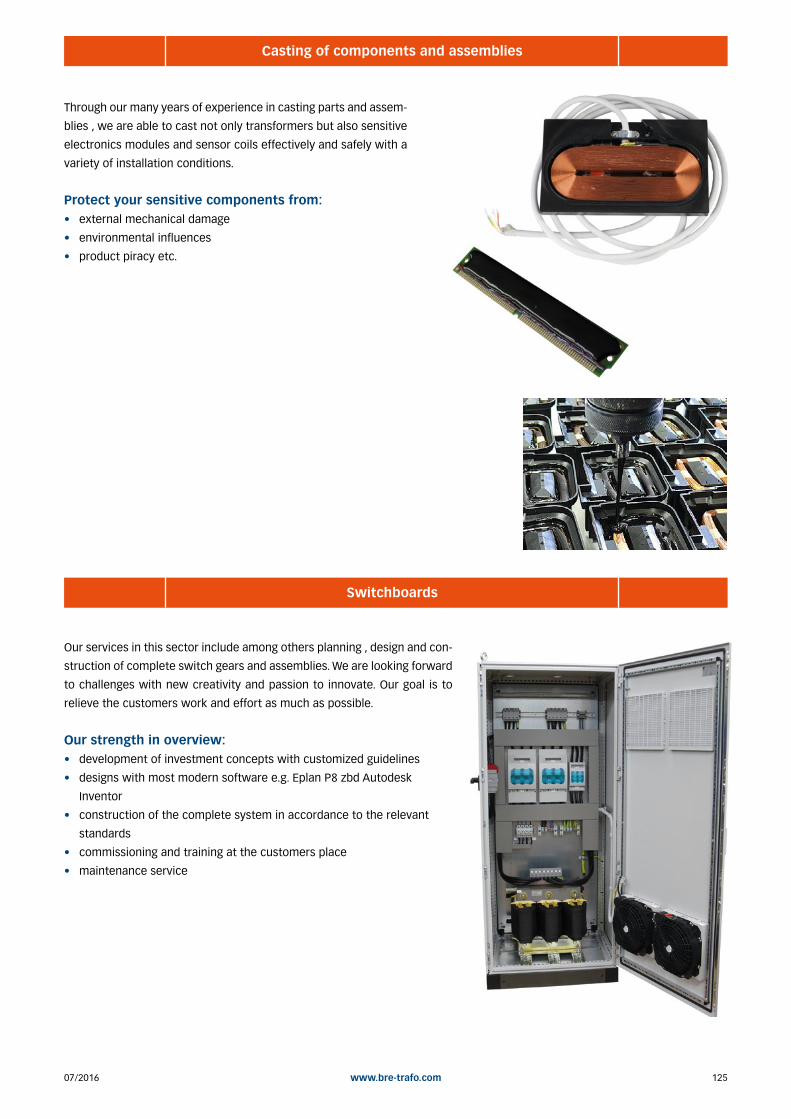
12507/2016 www.bre-trafo.com
Casting of components and assemblies
Switchboards
Through our many years of experience in casting parts and assem-
blies , we are able to cast not only transformers but also sensitive
electronics modules and sensor coils effectively and safely with a
variety of installation conditions.
Protect your sensitive components from: • external mechanical damage
• environmental influences
• product piracy etc.
Our services in this sector include among others planning , design and con-
struction of complete switch gears and assemblies. We are looking forward
to challenges with new creativity and passion to innovate. Our goal is to
relieve the customers work and effort as much as possible.
Our strength in overview:• development of investment concepts with customized guidelines
• designs with most modern software e.g. Eplan P8 zbd Autodesk
Inventor
• construction of the complete system in accordance to the relevant
standards
• commissioning and training at the customers place
• maintenance service
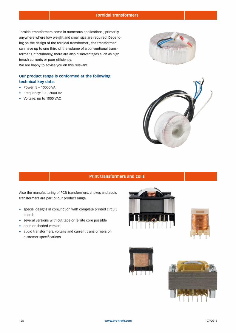
07/2016126 www.bre-trafo.com
Toroidal transformers
Print transformers and coils
Toroidal transformers come in numerous applications , primarily
anywhere where low weight and small size are required. Depend-
ing on the design of the toroidal transformer , the transformer
can have up to one third of the volume of a conventional trans-
former. Unfortunately, there are also disadvantages such as high
inrush currents or poor efficiency.
We are happy to advise you on this relevant.
Our product range is conformed at the following technical key data:• Power: 5 – 10000 VA
• Frequency: 10 – 2000 Hz
• Voltage: up to 1000 VAC
Also the manufacturing of PCB transformers, chokes and audio
transformers are part of our product range.
• special designs in conjunction with complete printed circuit
boards
• several versions with cut tape or ferrite core possible
• open or sheded version
• audio transformers, voltage and current transformers on
customer specifications
12707/2016 www.bre-trafo.com
General delivery conditions
Article I: General Provisions
1. Legal relations between Supplier and Purchaser in connection with supplies and/or services of the Supplier (hereinafter referred
to as „Supplies“) shall be solely governed by the present GL. The Purchaser‘s general terms and conditions shall apply only if
expressly accepted by the Supplier in writing. The scope of delivery shall be determined by the congruent mutual written declarations.
2. The Supplier herewith reserves any industrial property rights and/or copyrights pertaining to its cost estimates, drawings and other
documents (hereinafter referred to as „Documents“). The Documents shall not be made accessible to third parties without the
Supplier‘s prior consent and shall, upon request, be returned without undue delay to the Supplier if the contract is not awarded to
the Supplier. Sentences 1 and 2 shall apply mutatis mutandis to the Purchaser‘s Documents; these may, however, be made
accessible to those third parties to whom the Supplier has rightfully subcontracted Supplies.
3. The Purchaser has the non-exclusive right to use standard software and firmware, provided that it remains unchanged, is used
within the agreed performance parameters, and on the agreed equipment. Without express agreement the Purchaser may make one
back-up copy of standard software.
4. Partial deliveries are allowed, unless they are unreasonable to accept for the Purchaser.
5. The term „claim for damages“ used in the present GL also includes claims for indemnification for useless expenditure.
Article II: Prices, Terms of Payment, and Set-Off
1. Prices are ex works and excluding packaging; value added tax shall be added at the then applicable rate.
2. If the Supplier is also responsible for assembly or erection and unless otherwise agreed, the Purchaser shall pay the agreed
remuneration and any incidental costs required, e. g. for traveling and transport as well as allowances.
3. Payments shall be made free Supplier‘s paying office.
4. The Purchaser may set off only those claims which are undisputed or non- appealable.
Article III: Retention of Title
1. The items pertaining to the Supplies („Retained Goods“) shall remain the Supplier‘s property until each and every claim the Supplier
has against the Purchaser on account of the business relationship has been fulfilled. If the combined value of the Supplier‘s security
interests exceeds the value of all secured claims by more than 20 %, the Supplier shall release a corresponding part of the security
interest if so requested by the Purchaser; the Supplier shall be entitled to choose which security interest it wishes to release.
2. For the duration of the retention of title, the Purchaser may not pledge the Retained Goods or use them as security, and resale shall
be possible only for resellers in the ordinary course of their business and only on condition that the reseller receives payment from
its customer or makes the transfer of property to the customer dependent upon the customer fulfilling its obligation to effect
payment.
3. Should Purchaser resell Retained Goods, it assigns to the Supplier, already today, all claims it will have against its customers out of
the resale, including any collateral rights and all balance claims, as security, without any subsequent declarations to this effect
being necessary. If the Retained Goods are sold on together with other items and no individual price has been agreed with respect
to the Retained Goods, Purchaser shall assign to the Supplier such fraction of the total price claim as is attributable to the price of
the Retained Goods invoiced by Supplier.
4. a) Purchaser may process, amalgamate or combine Retained Goods with other items. Processing is made for Supplier. Purchaser
shall store the new item thus created for Supplier, exercising the due care of a diligent business person. The new items are
considered as Retained Goods.
b) Already today, Supplier and Purchaser agree that if Retained Goods are combined or amalgamated with other items that are not
the property of Supplier, Supplier shall acquire co-ownership in the new item in proportion of the value of the Retained Goods
combined or amalgamated to the other items at the time of combination or amalgamation. In this respect, the new items are
considered as Retained Goods.
c) The provisions on the assignment of claims according to No. 3 above shall also apply to the new item. The assignment, however,
shall only apply to the amount corresponding to the value invoiced by Supplier for the Retained Goods that have been processed,
combined or amalgamated.
d) Where Purchaser combines Retained Goods with real estate or movable goods, it shall, without any further declaration being
necessary to this effect, also assign to Supplier as security its claim to consideration for the combination, including all collateral
General Conditions for the Supply of Products and Services of the Electrical and Electronics Industry („Grüne Lieferbedingungen“ – GL)
07/2016128 www.bre-trafo.com
General delivery conditions
rights for the pro- rata amount of the value the combined Retained Goods have on the other combined items at the time of the
combination.
5. Until further notice, Purchaser may collect assigned claims relating to the resale. Supplier is entitled to withdraw Purchaser‘s
permission to collect funds for good reason, including, but not limited to delayed payment, suspension of payments, start of insol-
vency proceedings, protest or justified indications for overindebtedness or pending insolvency of Purchaser. In addition, Supplier
may, upon expiry of an adequate period of notice disclose the assignment, realize the claims assigned and demand that Purchaser
informs its customer of the assignment..
6. The Purchaser shall inform the Supplier forthwith of any seizure or other act of intervention by third parties. If a reasonable interest
can be proven, Purchaser shall, without undue delay, provide Supplier with the information and/or Documents necessary to assert
the claims it has against its customers.
7. Where the Purchaser fails to fulfill its duties, fails to make payment due, or otherwise violates its obligations the Supplier shall be
entitled to rescind the contract and take back the Retained Goods in the case of continued failure following expiry of a reasonable
remedy period set by the Supplier; the statutory provisions providing that a remedy period is not needed shall be unaffected. The
Purchaser shall be obliged to return the Retained Goods. The fact that the Supplier takes back Retained Goods and/or exercises the
retention of title, or has the Retained Goods seized, shall not be construed to constitute a rescission of the contract, unless the
Supplier so expressly declares.
Article IV: Time for Supplies; Delay
1. Times set for Supplies shall only be binding if all Documents to be furnished by the Purchaser, necessary permits and approvals,
especially concerning plans, are received in time and if agreed terms of payment and other obligations of the Purchaser are fulfilled.
If these conditions are not fulfilled in time, times set shall be extended reasonably; this shall not apply if the Supplier is responsible
for the delay.
2. If non-observance of the times set is due to:
a) force majeure, such as mobilization, war, terror attacks, rebellion or similar events (e. g. strike or lockout);
b) virus attacks or other attacks on the Supplier’s IT systems occurring despite protective measures were in place that complied
with the principles of proper care;
c) hindrances attributable to German, US or otherwise applicable national, EU or international rules of foreign trade law or to other
circumstances for which Supplier is not responsible; or
d) the fact that Supplier does not receive its own supplies in due time or in due form such times shall be extended accordingly.
3. If the Supplier is responsible for the delay (hereinafter referred to as „Delay“) and the Purchaser has demonstrably suffered a loss
therefrom, the Purchaser may claim a compensation as liquidated damages of 0.5 % for every completed week of Delay, but in no
case more than a total of 5 % of the price of that part of the Supplies which due to the Delay could not be put to the intended use.
4. Purchaser‘s claims for damages due to delayed Supplies as well as claims for damages in lieu of performance exceeding the limits
specified in No. 3 above are excluded in all cases of delayed Supplies, even upon expiry of a time set to the Supplier to effect the
Supplies. This shall not apply in cases of liability based on intent, gross negligence, or due to loss of life, bodily injury or damage to
health. Rescission of the contract by the Purchaser based on statute is limited to cases where the Supplier is responsible for the
delay. The above provisions do not imply a change in the burden of proof to the detriment of the Purchaser.
5. At the Supplier‘s request, the Purchaser shall declare within a reasonable period of time whether it, due to the delayed Supplies,
rescinds the contract or insists on the delivery of the Supplies.
6. If dispatch or delivery, due to Purchaser‘s request, is delayed by more than one month after notification of the readiness for dispatch
was given, the Purchaser may be charged, for every additional month commenced, storage costs of 0.5 % of the price of the items
of the Supplies, but in no case more than a total of 5 %. The parties to the contract may prove that higher or, as the case may be,
lower storage costs have been incurred.
Article V: Passing of Risk
1. Even where delivery has been agreed freight free, the risk shall pass to the Purchaser as follows:
a) if the delivery does not include assembly or erection, at the time when it is shipped or picked up by the carrier. Upon the
Purchaser’s request, the Supplier shall insure the delivery against the usual risks of transport at the Purchaser’s expense;
b) if the delivery includes assembly or erection, at the day of taking over in the Purchaser’s own works or, if so agreed, after a
successful trial run.
2. The risk shall pass to the Purchaser if dispatch, delivery, the start or performance of assembly or erection, the taking over in the
Purchaser’s own works, or the trial run is delayed for reasons for which the Purchaser is responsible or if the Purchaser has other-
wise failed to accept the Supplies.
12907/2016 www.bre-trafo.com
General delivery conditions
Article VI: Assembly and Erection
Unless otherwise agreed in written form, assembly and erection shall be subject to the following provisions:
1. Purchaser shall provide at its own expense and in due time:
a) all earth and construction work and other ancillary work outside the Supplier’s scope, including the necessary skilled and
unskilled labor, construction materials and tools;
b) the equipment and materials necessary for assembly and commissioning such as scaffolds, lifting equipment and other devices
as well as fuels and lubricants;
c) energy and water at the point of use including connections, heating and lighting;
d) suitable dry and lockable rooms of sufficient size adjacent to the site for the storage of machine parts, apparatus, materials, tools,
etc. and adequate working and recreation rooms for the erection personnel, including sanitary facilities as are appropriate in the
specific circumstances; furthermore, the Purchaser shall take all measures it would take for the protection of its own
possessions to protect the possessions of the Supplier and of the erection personnel at the site;
e) protective clothing and protective devices needed due to particular conditions prevailing on the specific site.
2. Before the erection work starts, the Purchaser shall unsolicitedly make available any information required concerning the location
of concealed electric power, gas and water lines or of similar installations as well as the necessary structural data.
3. Prior to assembly or erection, the materials and equipment necessary for the work to start must be available on the site of assembly
or erection and any preparatory work must have advanced to such a degree that assembly or erection can be started as agreed and
carried out without interruption. Access roads and the site of assembly or erection must be level and clear.
4. If assembly, erection or commissioning is delayed due to circumstances for which the Supplier is not responsible, the Purchaser shall
bear the reasonable costs incurred for idle times and any additional traveling expenditure of the Supplier or the erection personnel.
5. The Purchaser shall attest to the hours worked by the erection personnel towards the Supplier at weekly intervals and the Purchaser
shall immediately confirm in written form if assembly, erection or commissioning has been completed.
6. If, after completion, the Supplier demands acceptance of the Supplies, the Purchaser shall comply therewith within a period of two
weeks. The same consequences as upon acceptance arise if and when the Purchaser lets the twoweek period expire or the Supplies
are put to use after completion of agreed test phases, if any.
Article VII: Receiving Supplies
The Purchaser shall not refuse to receive Supplies due to minor defects.
Article VIII: Defects as to Quality
The Supplier shall be liable for defects as to quality (“Sachmängel”, hereinafter referred to as “Defects”,) as follows:
1. Defective parts or defective services shall be, at the Supplier’s discretion, repaired, replaced or provided again free of charge,
provided that the reason for the Defect had already existed at the time when the risk passed.
2. Claims for repair or replacement are subject to a statute of limitations of 12 months calculated from the start of the statutory statute
of limitations; the same shall apply mutatis mutandis in the case of rescission and reduction. This shall not apply where longer
periods are prescribed by law according to Sec. 438 para. 1 No. 2 (buildings and things used for a building), Sec. 479 para. 1 (right
of recourse), and Sec. 634a para. 1 No. 2 (defects of a building) German Civil Code (“Bürgerliches Gesetzbuch”), in the case of intent,
fraudulent concealment of the Defect or non-compliance with guaranteed characteristics (“Beschaffenheitsgarantie”). The legal
provisions regarding suspension of the statute of limitations (“Ablaufhemmung”, “Hemmung”) and recommencement of limitation
periods shall be unaffected.
3. Notifications of Defect by the Purchaser shall be given in written form without undue delay.
4. In the case of notification of a Defect, the Purchaser may withhold payments to an amount that is in a reasonable proportion to the
Defect. The Purchaser, however, may withhold payments only if the subject-matter of the notification of the Defect involved is
justified and incontestable. The Purchaser has no right to withhold payments to the extent that its claim of a Defect is time-barred.
Unjustified notifications of Defect shall entitle the Supplier to demand reimbursement of its expenses by the Purchaser.
5. The Supplier shall be given the opportunity to repair or to replace the defective good (“Nacherfüllung”) within a reasonable period of
time.
6. If repair or replacement is unsuccessful, the Purchaser is entitled to rescind the contract or reduce the remuneration; any claims for
damages the Purchaser may have according to No. 10 shall be unaffected.
7. There shall be no claims based on Defect in cases of insignificant deviations from the agreed quality, of only minor impairment of
usability, of natural wear and tear, or damage arising after the passing of risk from faulty or negligent handling, excessive strain,
unsuitable equipment, defective civil works, inappropriate foundation soil, or claims based on particular external influences not
assumed under the contract, or from non-reproducible software errors. Claims based on defects attributable to improper modifi-
07/2016130 www.bre-trafo.com
General delivery conditions
cations or repair work carried out by the Purchaser or third parties and the consequences thereof are likewise excluded.
8. The Purchaser shall have no claim with respect to expenses incurred in the course of supplementary performance, including costs
of travel, transport, labor, and material, to the extent that expenses are increased because the subjectmatter of the Supplies has
subsequently been brought to another location than the Purchaser’s branch office, unless doing so complies with the normal use of
the Supplies.
9. The Purchaser’s right of recourse against the Supplier pursuant to Sec. 478 BGB is limited to cases where the Purchaser has not
concluded an agreement with its customers exceeding the scope of the statutory provisions governing claims based on Defects.
Moreover, No. 8 above shall apply mutatis mutandis to the scope of the right of recourse the Purchaser has against the Supplier
pursuant to Sec. 478 para. 2 BGB.
10. The Purchaser shall have no claim for damages based on Defects. This shall not apply to the extent that a Defect has been frau-
dulently concealed, the guaranteed characteristics are not complied with, in the case of loss of life, bodily injury or damage to health,
and/or intentionally or grossly negligent breach of contract on the part of the Supplier. The above provisions do not imply a change
in the burden of proof to the detriment of the Purchaser. Any other or additional claims of the Purchaser exceeding the claims
provided for in this Article VIII, based on a Defect, are excluded.
Article IX: Industrial Property Rights and Copyrights; Defects in Title
1. Unless otherwise agreed, the Supplier shall provide the Supplies free from third parties’ industrial property rights and copyrights
(hereinafter referred to as “IPR”) with respect to the country of the place of delivery only. If a third party asserts a justified claim
against the Purchaser based on an infringement of an IPR by the Supplies made by the Supplier and used in conformity with the
contract, the Supplier shall be liable to the Purchaser within the time period stipulated in Article VIII No. 2 as follows:
a) The Supplier shall choose whether to acquire, at its own expense, the right to use the IPR with respect to the Supplies concerned
or whether to modify the Supplies such that they no longer infringe the IPR or replace them. If this would be impossible for the
Supplier under reasonable conditions, the Purchaser may rescind the contract or reduce the remuneration pursuant to the
applicable statutory provisions;
b) The Supplier’s liability to pay damages is governed by Article XII;
c) The above obligations of the Supplier shall apply only if the Purchaser (i) immediately notifies the Supplier of any such claim
asserted by the third party in written form, (ii) does not concede the existence of an infringement and (iii) leaves any pro-
tective measures and settlement negotiations to the Supplier’s discretion. If the Purchaser stops using the Supplies in order to
reduce the damage or for third party that no acknowledgement of the alleged infringement may be inferred from the fact that
the use has been discontinued.
2. Claims of the Purchaser shall be excluded if it is responsible for the infringement of an IPR.
3. Claims of the Purchaser are also excluded if the infringement of the IPR is caused by specifications made by the Purchaser, by a
type of use not foreseeable by the Supplier or by the Supplies being modified by the Purchaser or being used together with products
not provided by the Supplier.
4. In addition, with respect to claims by the Purchaser pursuant to No. 1 a) above, Article VIII Nos. 4, 5, and 9 shall apply mutatis
mutandis in the event of an infringement of an IPR.
5. Where other defects in title occur, Article VIII shall apply mutatis mutandis.
6. Any other claims of the Purchaser against the Supplier or its agents or any such claims exceeding the claims provided for in this
Article IX, based on a defect in title, are excluded.
Article X: Conditional Performance
1. The performance of this contract is conditional upon that no hindrances attributable to German, US or otherwise applicable national,
EU or international rules of foreign trade law or any embargos or other sanctions exist.
2. The Purchaser shall provide any information and Documents required for export, transport and import purposes.
Article XI: Impossibility of Performance; Adaptation of Contract
1. To the extent that delivery is impossible, the Purchaser is entitled to claim damages, unless the Supplier is not responsible for the
impossibility. The Purchaser’s claim for damages is, however, limited to an amount of 10 % of the value of the part of the Supplies
which, owing to the impossibility, cannot be put to the intended use. This limitation shall not apply in the case of liability based on
intent, gross negligence or loss of life, bodily injury or damage to health; this does not imply a change in the burden of proof to the
detriment of the Purchaser. The Purchaser’s right to rescind the contract shall be unaffected.
2. Where events within the meaning of Article IV No. 2 (a) to (c) substantially change the economic importance or the contents of the
Supplies or considerably affect the Supplier’s business, the contract shall be adapted taking into account the principles of reaso-

13107/2016 www.bre-trafo.com
nableness and good faith. To the extent this is not justifiable for economic reasons, the Supplier shall have the right to rescind the
contract. The same applies if required export permits are not granted or cannot be used. If the Supplier intends to exercise its right
to rescind the contract, it shall notify the Purchaser thereof without undue delay after having realized the repercussions of the event;
this shall also apply even where an extension of the delivery period has previously been agreed with the
Article XII: Other Claims for Damages
1. Unless otherwise provided for in the present GL, the Purchaser has no claim for damages based on whatever legal reason, including
infringement of duties arising in connection with the contract or tort.
2. This does not apply if liability is based on:
a) the German Product Liability Act (“Produkthaftungsgesetz”);
b) intent;
c) gross negligence on the part of the owners, legal representatives or executives;
d) fraud;
e) failure to comply with a guarantee granted;
f) negligent injury to life, limb or health; or
g) negligent breach of a fundamental condition of contract (“wesentliche Vertragspflichten”).
However, claims for damages arising from a breach of a fundamental condition of contract shall be limited to the foreseeable damage
which is intrinsic to the contract, provided that no other of the above case applies.
3. The above provision does not imply a change in the burden of proof to the detriment of the Purchaser.
Artikel XIII: Venue and Applicable law
1. If the Purchaser is a businessman, sole venue for all disputes arising directly or indirectly out of the contract shall be the Supplier’s
place of business. However, the Supplier may also bring an action at the Purchaser’s place of business.
2. This contract and its interpretation shall be governed by German law, to the exclusion of the United Nations Convention on contracts
for the International Sale of Goods (CISG).
Article XIV: Severability Clause
The legal invalidity of one or more provisions of this Agreement in no way affects the validity of the remaining provisions. This shall not
apply if it would be unreasonably onerous for one of the parties to be obligated to continue the contract.
General delivery conditions
07/2016132 www.bre-trafo.com
Supplementary Clause: Extended Retention of Title
The following Basic and Extended Retention of Title shall be agreed:
1. The items pertaining to the Supplies (“Retained Goods”) shall remain the Supplier’s property until each and every claim the Supplier
has against the Purchaser on account of the business relationship has been fulfilled. If the combined value of the Supplier’s security
interests exceeds the value of all secured claims by more than 20 %, the Supplier shall release a corresponding part of the security
interest if so requested by the Purchaser; the Supplier shall be entitled to choose which security interest it wishes to release.
2. For the duration of the retention of title, the Purchaser may not pledge the Retained Goods or use them as security, and resale shall
be possible only for resellers in the ordinary course of their business and only on condition that the reseller receives payment from
its customer or makes the transfer of property to the customer dependent upon the customer fulfilling its obligation to effect
payment.
3. Should Purchaser resell Retained Goods, it assigns to the Supplier, already today, all claims it will have against its customers out of
the resale, including any collateral rights and all balance claims, as security, without any subsequent declarations to this effect
being necessary. If the Retained Goods are sold on together with other items and no individual price has been agreed with respect
to the Retained Goods, Purchaser shall assign to the Supplier such fraction of the total price claim as is attributable to the price of
the Retained Goods invoiced by Supplier.
4. a) Purchaser may process, amalgamate or combine Retained Goods with other items. Processing is made for Supplier. Purchaser
shall store the new item thus created for Supplier, exercising the due care of a diligent business person. The new items are
considered as Retained Goods.
b) Already today, Supplier and Purchaser agree that if Retained Goods are combined or amalgamated with other items that are not
the property of Supplier, Supplier shall acquire co-ownership in the new item in proportion of the value of the Retained Goods
combined or amalgamated to the other items at the time of combination or amalgamation. In this respect, the new items are
considered as Retained Goods.
c) The provisions on the assignment of claims according to No. 3 above shall also apply to the new item. The assignment, however,
shall only apply to the amount corresponding to the value invoiced by Supplier for the Retained Goods that have been processed,
combined or amalgamated.
d) Where Purchaser combines Retained Goods with real estate or movable goods, it shall, without any further declaration being
necessary to this effect, also assign to Supplier as security its claim to consideration for the combination, including all collateral
rights for the pro-rat amount of the value the combined Retained Goods have on the other combined items at the time of the
combination.
5. Until further notice, Purchaser may collect assigned claims relating to the resale. Supplier is entitled to withdraw Purchaser’s
permission to collect funds for good reason, including, but not limited to delayed payment, suspension of payments, start of
insolvency proceedings, protest or justified indications for overindebtedness or pending insolvency of Purchaser. In addition,
Supplier may, upon expiry of an adequate period of notice disclose the assignment, realize the claims assigned and demand that
Purchaser informs its customer of the assignment.
6. The Purchaser shall inform the Supplier forthwith of any seizure or other act of intervention by third parties. If a reasonable interest
can be proven, Purchaser shall, without undue delay, provide Supplier with the information and/or Documents necessary to assert
the claims it has against its customers.
7. Where the Purchaser fails to fulfill its duties, fails to make payment due, or otherwise violates its obligations the Supplier shall be
entitled to rescind the contract and take back the Retained Goods in the case of continued failure following expiry of a reasonable
remedy period set by the Supplier; the statutory provisions providing that a remedy period is not needed shall be unaffected. The
Purchaser shall be obliged to return the Retained Goods. The fact that the Supplier takes back Retained Goods and/or exercises the
retention of title, or has the Retained Goods seized, shall not be construed to constitute a rescission of the contract, unless the
Supplier so expressly declares.
General delivery conditions

13307/2016 www.bre-trafo.com
Notes

07/2016134 www.bre-trafo.com
Notes

13507/2016 www.bre-trafo.com

Breimer-Roth Transformatorenwerk GmbHOstring 11–13 · 64711 Erbach R
evis
ion
07/2
016
Fon +49 (0)60 62 - 9 42 50Fax +49 (0)60 62 - 20 [email protected] www.bre-trafo.com