Compatibility and Composition Rules - svpro.ru 1200 Configuration Rules.pdf · Marconi is part of...
78
Ericssonwide Internal DIMENSIONING RULES Prepared (also subject responsible if other) No. ETL/G/S Peter Barwick 192 02-FGC 101 901 Approved Checked Date Rev Reference ETL/G/S Karl-Eric K Malberg 16/02/2006 B Marconi is part of the Ericsson group. The Ericsson Optical Network is a transport network portfolio provided in conjunction with Marconi. It includes SDH and DWDM NE’s and a common NMS system. The portfolio is both broad and complete. OMS 1200 Family R3.x Compatibility and Composition Rules Abstract: INFORMATION FOR ERICSSON USER Note from Product Management: This document (not to be issued to customers) provides visibility of the OMS 1200 Family Composition Rules for R3.x. This document should be used in conjunction with the Provisioning and Control Document to generate a ‘Bill of Quantities’ for Customer Solutions. The BOQ will be a list of Marconi Saleable Entity Codes (SE). Both Hardware and Software are purchased using Marconi SE Codes
Transcript of Compatibility and Composition Rules - svpro.ru 1200 Configuration Rules.pdf · Marconi is part of...

Ericssonwide Internal DIMENSIONING RULES
Prepared (also subject responsible if other) No.
ETL/G/S Peter Barwick 192 02-FGC 101 901 Approved Checked Date Rev Reference
ETL/G/S Karl-Eric K Malberg 16/02/2006 B
Marconi is part of the Ericsson group. The Ericsson Optical Network is a transport network portfolio provided in conjunction with Marconi. It includes SDH and DWDM NE’s and a common NMS system. The portfolio is both broad and complete.
OMS 1200 Family R3.x
Compatibility and Composition Rules
Abstract: INFORMATION FOR ERICSSON USER
Note from Product Management: This document (not to be issued to customers) provides visibility of the OMS 1200 Family Composition Rules for R3.x. This document should be used in conjunction with the Provisioning and Control Document to generate a ‘Bill of Quantities’ for Customer Solutions. The BOQ will be a list of Marconi Saleable Entity Codes (SE). Both Hardware and Software are purchased using Marconi SE Codes

SMA1/4/16 UC & EX - PROVISIONING CONTROL DOCUMENT
1ADR 60773 AAC-CTA Copyright - Refer to Title Page Page 01 Issue 7
SMA ULTRA COMPACT AND EXPANDED ULTRA COMPACT
PROVISIONING CONTROL DOCUMENT
This is a Marconi Communications Specification authorised for use by:
Nick Kings SMA1/4/16 Engineering Manager AC4521 Product Engineering Beeston
The information contained herein is the responsibility of and is approved by the following, to whom all enquiries should be directed in the first instance:
Jon Knight SMA1/4/16UC/EX Product Champion AC4521 Product Engineering Beeston
Dave Nettleton SMA1/4/16UC/EX Product Champion AC4521 Product Engineering Beeston
This is an unpublished work the copyright in which vests in Marconi Communications Limited. All rights reserved. The information contained herein is confidential and the property of Marconi Communications Limited and is supplied without liability for
errors or omissions. No part may be reproduced, disclosed or used except as authorised by contract or other written permission. The copyright and the foregoing restriction on reproduction and use extend to all media in which the information may be embodied.

SMA ULTRA COMPACT AND EXPANDED ULTRA COMPACT PROVISIONING CONTROL DOCUMENT
1ADR 60773 AAC-CTA Copyright - Refer to Title Page Page 2 Issue 7
0.1 CONTENTS
0.1 CONTENTS.................................................................................................................................................2 0.2 HISTORY ....................................................................................................................................................4 0.3 ISSUE CONTROL.......................................................................................................................................5 0.4 REFERENCES.............................................................................................................................................5 0.5 GLOSSARY OF TERMS.............................................................................................................................6
1 INTRODUCTION ......................................................................................................................................101
2 OVERVIEW OF THE PRODUCT ...........................................................................................................201
2.1 SMA1/4UC ..............................................................................................................................................201 2.2 SMA1/4EX...............................................................................................................................................203 2.3 SMA1/4/16UC/EX...................................................................................................................................203 2.4 NETWORK MANAGEMENT ................................................................................................................204 2.5 EXPORT LICENCE ................................................................................................................................204
3 UC PRODUCT STRUCTURE ..................................................................................................................301
3.1 EQUIPING/CONFIGURATION RULES................................................................................................302 3.2 SALEABLE ENITITIES..........................................................................................................................303
4 EX PRODUCT STRUCTURE...................................................................................................................401
4.1 EQUIPING/CONFIGURATION RULES...........................................................................................................401 4.2 SALEABLE ENITITIES .................................................................................................................................407
5 SMA ULTRA COMPACT AND EXTENDED ULTRA COMPACT (UC & EX) SALEABLE ENTITIES .............................................................................................................................................................501
5.1 CORE SYSTEM ......................................................................................................................................501 5.2 ITEMS ASSOCIATED WITH THE CORE .............................................................................................504 5.3 SFP TRIB & LINE INTERFACES ..........................................................................................................506 5.4 2MBIT/S TRIBUTARY INTERFACES..................................................................................................506 5.5 GENERIC TRIBUTARY CARDS...........................................................................................................510 5.6 COMMS/AUX/ANCILLARY CARD SP53B .........................................................................................514 5.7 EMC COVERS ........................................................................................................................................514 5.8 BACKUP AND LCT S/W........................................................................................................................515 5.9 MISCELLANEOUS ................................................................................................................................515 5.10 SPARES SP97** .................................................................................................................................516 0.1 SMA UC AC POWER & BATTERY BACKUP......................................................................................517 5.11 ....................................................................................................................................................................517
6 TRAFFIC INTERFACES..........................................................................................................................601
6.1 LINE SLOTS............................................................................................................................................601 6.2 OPTICAL TRIBUTARY CARDS ...........................................................................................................601 6.3 ELECTRICAL TRIBUTARY CARDS (FRONT PANEL ACCESS)......................................................603 6.4 ELECTRICAL TRIBUTARY CARDS (LTU ACCESS).........................................................................604
7 NON-TRAFFIC EXTERNAL INTERFACES.........................................................................................701
7.1 POWER/LCT LTU INTERFACES..........................................................................................................701 7.2 COMMS/AUX/ANCILLARY CARD INTERFACES ............................................................................702 7.3 AC POWER & BATTERY BACKUP UNIT.....................................................................................................704
8 MONITOR POINTS & TEST BUS ..........................................................................................................801
8.1 34/45MBIT/S ...........................................................................................................................................801 8.2 140/155MBIT/S .......................................................................................................................................801 8.3 CONVENTIONAL STM-1 OPTICAL ....................................................................................................801 8.4 DUAL STM-1 OPTICAL AND QUAD STM-1 OPTICAL/ELECTRICAL............................................801 8.5 CONVENTIONAL STM-1 ELECTRICAL.............................................................................................802 8.6 DUAL STM-1 ELECTRICAL .................................................................................................................802

SMA ULTRA COMPACT AND EXPANDED ULTRA COMPACT PROVISIONING CONTROL DOCUMENT
1ADR 60773 AAC-CTA Copyright - Refer to Title Page Page 3 Issue 7
8.7 2MBIT/S TESTBUS ................................................................................................................................802
9 COMMUNICATIONS ...............................................................................................................................901
9.1 IS-IS TABLE SPACE ..............................................................................................................................901
10 AUXILLARY AND ANCILLARY FUNCTIONALITY.......................................................................1001
10.1 COMMS/AUXILIARY/ANCILLARY CARD (SP53B) ..................................................................1001 10.2 EXTERNAL EOW UNIT (SP52A)...................................................................................................1002
11 LOCAL TERMINAL AND ELEMENT SOFTWARE .........................................................................1101
11.1 LCT HARDWARE ...........................................................................................................................1101 11.2 LCT & BACKUP SOFTWARE ........................................................................................................1102 11.3 LCT OPERATING SYSTEM ...........................................................................................................1102 11.4 NETWORK ELEMENT SOFTWARE .............................................................................................1102 11.5 CELLSPAN CARDS.........................................................................................................................1103 11.6 PACKETSPAN CARDS ...................................................................................................................1103 11.7 LAYER 2 CARDS.............................................................................................................................1103
12 CARD FACIA ...........................................................................................................................................1201
13 EMC COVERS .........................................................................................................................................1301
13.1 UNEQUIPPED SLOT COVERS.......................................................................................................1301
14 MECHANICAL DETAILS......................................................................................................................1401
14.1 SUBRACK MOUNTING..................................................................................................................1401 14.2 UNIT DIMENSIONS........................................................................................................................1401 14.3 WEIGHTS.........................................................................................................................................1402 14.4 RECOMMENDED RACKS FOR HOUSING SMA SUBRACKS/UNITS ......................................1403 14.5 OPTICAL FIBRE AND CABLE DRESSING...................................................................................1403 14.6 SUBRACK INSTALLATION ..........................................................................................................1403
15 RECOMMENDED CABLES, CONNECTORS, CABLE ASSEMBLIES AND KITS OF PARTS..1501
15.1 RECOMMENDED CABLES............................................................................................................1501 15.2 PRE MADE CABLE ASSEMBLIES ................................................................................................1504 15.3 CONNECTOR KITS OF PARTS......................................................................................................1506
16 POWER CONSUMPTION AND EQUIPMENT PROTECTION .......................................................1601
16.1 POWER CONSUMPTION FIGURES..............................................................................................1601 16.2 TYPICAL POWER CALCULATION ..............................................................................................1602 16.3 EXTERNAL PROTECTIVE DEVICE (EPD) ..................................................................................1602 16.4 MULTIPLE SUBRACK MOUNTING .............................................................................................1604
17 RELIABILITY..........................................................................................................................................1701
17.1 SMA CARD MTBF PREDICTIONS ................................................................................................1701
18 STANDARDS AND APPROVALS .........................................................................................................1801
18.1 ENVIRONMENTAL SPECIFICATION ..........................................................................................1801 18.2 SAFETY............................................................................................................................................1801 18.3 REPORTS .........................................................................................................................................1802

SMA ULTRA COMPACT AND EXPANDED ULTRA COMPACT PROVISIONING CONTROL DOCUMENT
1ADR 60773 AAC-CTA Copyright - Refer to Title Page Page 4 Issue 7
0.2 HISTORY
Change No. Issue
Details Of Change
N/A 1a First Draft Issue Author: Name Andy Hargreaves Department AC4521 Site Beeston
N/A 1 First issue. Changes incorporated after review of issue 1a. Author: Name Andy Hargreaves Department AC4521 Site Beeston
ECN6031022 2 SE codes added for SFPs (+ description change) Bracket information changed 1.5M References removed EMC ME and SE codes added IPS table added Author: Name Andy Hargreaves Department AC4521 Site Beeston
ECN6031823 3 Following SE codes added:- SFP-E SU65AA 140M Trib & LTU SN64CF STM-1e Trib and LTU SP65TA Release 3 Backup S/W and LCT CD-ROM SP81C EOW SP52A Blank Optical Module KOP SP73A LCT (Windows 2000) NH40F LCT (Windows XP) NH40G Following SEs modified:- SMA1/4UC Core SP03A Horizontal mounting/Cooling assembly SP03B STM-1 Optical line Modules SU66**/SU67** Generic Trib EMC Cover SP73EA 140M Gen Trib Front access SN64CE 45M Trib and LTU SP63A DIN Options removed SN44AA/AC/AE/AG/AH Following SEs removed:- SMA LCT Software SA80A Various text updated. Weights, MTBF and dimensions added for UC units Section 14 (recommended cabling) text removed Author: Name Andy Hargreaves

SMA ULTRA COMPACT AND EXPANDED ULTRA COMPACT PROVISIONING CONTROL DOCUMENT
1ADR 60773 AAC-CTA Copyright - Refer to Title Page Page 5 Issue 7
Department AC4521 Site Beeston
ECN6032549 4 Extensive Saleable entity structure/code changes. Separate CQA document created which will be used as the authority on Saleable Entities. Main text changes. Section 19 (SE structures removed) and references to CQA (Structures Document) added. Section 14 text added (previously just had a title) Section 10 Extensively updated (Software) and details from previous section 18 (now deleted) incorporated. Author: Name Andy Hargreaves Department AC4521 Site Beeston
ECN6033263 5 New issue to add EX configuration information. Section 2 updated slightly to introduce EX sub-rack and STM-4/16 Core. Section 4 – “EX Product Structure” added to give details of EX configuration rules. Section 5 – “SMA Ultra Compact and Extended Ultra Compact (UC & EX) Saleable Entities” updated to add new EX SEs.
6 Updates for R3.3.1 Product Release:
7 Core SEs updated to remove s/w on CF card - must now be ordered separately. New UC Cores SP03AC & SP13AC introduced with PWR/LCT LTU removed. New PWR/LCT LTU SEs SP03DA & SP03DB introduced for use with SP03AC & SP13AC from Q1 2006. Fan Tray removed from SMA16EC & EX SEs and equipping rules updated. EX Power Feed Protection LTU SE SP97AD replaced by SP20D. Comms/Aux/Ancillary in SP53B replaced by Enhanced Comms/Aux/Ancillary. 2M Trib SE SP60C now calls up 2M card Version 2. SMA UC AC Power & Battery Backup SEs introduced
0.3 ISSUE CONTROL
Date 21 Mar 2003
25 Apr 2003
09 June 2003
03 Nov 2003
13 Sep
2004
04 Nov 2004
29 Nov 2004
17 May 2005
04 Nov 2005
Section All 1a 1 2 3 4 5A 5 6 7
0.4 REFERENCES
0.5.1 1QDE10274AAU-YYA Installation Guide for SDH Transmission Equipment. 0.5.2 1ADA61787AAF-BTA Architecture Specification for SMA1/4 UC 0.5.3 1AFB60007AAJ-YBA Netguide – Optical Budget Data 0.5.4 1QDA60005ACM-YYA Marketing Export Controls Procedure Spec 0.5.5 1QAA20148AAW-YYA Generic Hardware Procurement Specification 0.5.6 EN50082-1 European Standard (Class B - EN55022)

SMA ULTRA COMPACT AND EXPANDED ULTRA COMPACT PROVISIONING CONTROL DOCUMENT
1ADR 60773 AAC-CTA Copyright - Refer to Title Page Page 6 Issue 7
0.5.7 ETS 300 019-2 Equipment Engineering (EE):European Telecommunications Standard for Equipment Practice; Engineering Requirements for Subracks in misc Racks and Cabinets
0.5.8 EN 300 386-2 European Standard: Equipment Engineering Telecommunication Network Equipment Electromagnetic Requirements Part 2 Product Specific Compliance Criteria and Operating Conditions
0.5.9 ES 201 468 Enhanced Availability of Service Level 0.5.10 ETS 300 132-2 Equipment Engineering (EE):Power Supply Interface at
the input to Telecommunications Equipment 0.5.11 BTR 2511 British Telecommunications Requirements for
Telecommunication Power Requirements 0.5.12 EN 60950 European Standard: Safety of Information Technology
Equipment including Electrical Business Equipment 0.5.13 EN 60825-1 European Standard: Safety of Laser Products 0.5.14 1ADR60693AAB-CTA Series 4 SMA Provisioning Control Document 0.5.15 1ADR60773AAC-CQA SMA UC Structures and Rules Document 0.5.16 1ADR60674AAX-CTA Provisioning Control Document for ETSI Rack and
Associated Parts 0.5.17 03ADR00001AAF-CTA Packetspan II Product Provisioning Control Document
0.5 GLOSSARY OF TERMS
ADM Add Drop Multiplexer ATM Asynchronous Transfer Mode AUI Adaption Unit Interface CF Compact Flash DFW Dual Fibre Working ETA Ethernet Traffic Adapter LCT Local craft terminal LTU Line termination unit MM Multimode MTBF Mean time between failures PSU Power supply unit SDH Synchronous digital hierarchy SFW Single Fibre Working SMA1/4UC SMA1/4 Ultra Compact STM-1/4 Synchronous transport module VC Virtual container VC-12 Virtual container level (12) VCAM Virtual container access module VCTS Virtual container transport system ME Manufacturable Entity SE Saleable Entity
End of section

SMA ULTRA COMPACT AND EXPANDED ULTRA COMPACT PROVISIONING CONTROL DOCUMENT
1ADR 60773 AAC-CTA Copyright - Refer to Title Page Page 101 Issue 7
1 INTRODUCTION
This document specifies the provisioning and control rules for the Marconi Communications SMA1/4 Ultra Compact Product. The purpose of this document is to enable sales, commercial and planning to provision the product into SDH networks.
End of Section

SMA ULTRA COMPACT AND EXPANDED ULTRA COMPACT PROVISIONING CONTROL DOCUMENT
1ADR 60773 AAC-CTA Copyright - Refer to Title Page Page 201 Issue 7
2 OVERVIEW OF THE PRODUCT
2.1 SMA1/4UC
The SMA1/4UC is a full feature ADM, optimized for both SDH ring and terminal applications. The product is intended for applications requiring high volume 2Mbit/s transport at STM-1, for light traffic STM-4 applications that require the flexibility and protection options provided by a SIU sub-rack format. The equipment is also targeted for use in street/radio cabinets. It offers a flexible range of service deliveries including Ethernet. The product is also ideal for multi-tenanted buildings; it has the capacity to serve multiple businesses whilst minimizing space requirements. It provides delivery of STM-1/4 SDH functionality to the customer together with SDH ring and protected terminal applications through two line interfaces. The SMA1/4UC can be deployed in mobile radio networks for the collection and consolidation of traffic from radio base stations. The product has an extremely small footprint and flexible mounting options, vertical or horizontal, makes effective use of space. The SMA1/4UC is designed and built on the highly successful SMA and MSH product range. This will complement these products which are already deployed extensively in SDH Access Networks (in street cabinets, local exchanges and directly on customer premises). The SMA1/4UC can be deployed in networks with the existing Marconi SDH products. They can be used in mixed rings with and subtended from the existing ADMs. The SMA1/4UC is managed by Marconi’s Network Management, MV38, the Element Management system, MV36, or by a local terminal.
2.1.1 Main Features
• Next generation SDH Add/Drop Multiplexer with full, non-blocking, VC-12 cross connection capability.
• Compatible with the Marconi Corporations range of synchronous multiplexers.
• Two Line interfaces supporting ring and protected terminal applications.
• Support of SNCP and 1+1 MSP traffic protection.
• STM-1 (155 Mbit/s) and STM-4 (622 Mbit/s) aggregate options.
• Full, non-blocking, VC-12 cross connect capability Traffic ports: • 2Mbit/s, 34Mbit/s, 45Mbit/s, STM-1 (optical and electrical), STM-4
• Ethernet 10 BaseT & 100 BaseT
• Support of I.421 for primary rate ISDN.
• TCM for termination of inter-operator paths.

SMA ULTRA COMPACT AND EXPANDED ULTRA COMPACT PROVISIONING CONTROL DOCUMENT
1ADR 60773 AAC-CTA Copyright - Refer to Title Page Page 202 Issue 7
• Comprehensive configuration, fault and performance management features.
• Compact design, suitable for customer premises, meeting Class B EMC requirements.
• 4 port STM-1/4 multi-rate card with SFP modules offering flexibility and a full range of optical and electrical interfaces.
2.1.2 Add/Drop-Based Applications
Conventional SDH Add/Drop Multiplexers, designed for rack mounting in a network-operator environment, are being deployed in increasing numbers to deliver services to business customers with high bandwidth and high Quality of Service (QoS) requirements. The SMA1/4UC allows the operator to target the next tier of small and medium business customers, with a cost-effective solution designed specifically around customer-premises requirements in terms of environment and capacity. The SMA1/4UC can be deployed, as Network Termination Equipment (NTE), on customer premises. Applications include campus rings and multi-tenanted buildings. It will be deployed either as a terminal, in hubbing architectures, or as a ring based ADM. Traffic protection may be employed for both these applications, either 1+1 Multiplex Section Protection (MSP) or Sub Network Connection Protection (SNCP). The solution brings the major benefits associated with SDH delivery into the customer premises.
Figure 2.1 Network Configurations The product will also be deployed in mobile radio networks for the collection and consolidation of traffic from radio base stations. Other applications will see the SMA1/4UC deployed within the access network, particularly in street side cabinets.
MSH/SMA
MSH/SMACore Network
Customer Premises
SMA1/4 UC SMA1/4 UC + PacketSpan
SMA1/4 UC
SMA1/4c

SMA ULTRA COMPACT AND EXPANDED ULTRA COMPACT PROVISIONING CONTROL DOCUMENT
1ADR 60773 AAC-CTA Copyright - Refer to Title Page Page 203 Issue 7
Example applications include telephony where the product will be deployed alongside Primary Multiplexers, delivering narrow-band services to residential customers. The SMA1/4UC is designed to meet the ETSI and UK standards for Class B EMC, together with climatic, safety and regulatory standards appropriate to this environment.
2.1.3 Point to Point Applications
Although intended as a solution for integration within an SDH Network, the SMA1/4UC can also be used for point to point systems. This configuration can be used to support up to 63 x 2 Mbit/s for services such as 2 Mbit/s leased lines, direct connection to PBX’s and data.
2.2 SMA1/4EX
The SMA1/4EX is a larger version of the SMA1/4UC offering equivalent functionality to the SMA1/4UC and the following extra features: • Maximum capacity of 252 x 2Mbit/s balanced tributary access within the sub-rack.
• Maximum capacity of 126 x 2Mbit/s unbalanced tributary access within the sub-rack. (252 x 2Mbit/s unbalanced can be provided using balanced LTUs and external balanced-unbalanced conversion).
• 1:N 2 Mbit/s protection.
• Three generic tributary slots each having 2 x STM-1 bandwidth.
• Two generic tributary slots each having 4 x STM-1 bandwidth.
• Duplicated power LTU.
2.3 SMA1/4/16UC/EX
2.3.1 STM-4/16 Core Unit
The SMA1/4UC/EX uses the STM-1/4 Core/CCU unit. A new type of Core/CCU provides unduplicated STM-4/16 interfaces. This unit will be useable in both UC and EX sub-racks and provide upgrade to STM-16 aggregate line rate. The SMA4/16UC/EX will operate in the same way as the SMA1/4UC/EX with the following exceptions. • Two-fibre MS-SPRING at STM-4 and STM-16 line rates can be provided.
• The STM-4/16 Core/CCU has only one bi-directional STM-4/16 interface per unit therefore MSP operation is not provided.
• Two further generic tributary slots, each having 4 x STM-1 bandwidth, are available.

SMA ULTRA COMPACT AND EXPANDED ULTRA COMPACT PROVISIONING CONTROL DOCUMENT
1ADR 60773 AAC-CTA Copyright - Refer to Title Page Page 204 Issue 7
2.3.2 SMA1/4/16 and UC/EX Options
There will be four basic configurations of the product. • SMA1/4UC UC sub-rack with STM-1/4 Core/CCU card.
• SMA1/4EX EX sub-rack with STM-1/4 Core/CCU card.
• SMA4/16UC UC sub-rack with STM-4/16 Core/CCU card.
• SMA4/16EX EX sub-rack with STM-4/16 Core/CCU card. Note that the EX version of sub-rack will only support the following STM-1/4 tributary cards. • 4 Port STM-1/4 multi-rate card (with SFP modules).
• 2 port fixed STM-1 electrical interface (required for STM-1 operation with card protection).
• STM-4 VC-4 C/V contiguous to virtual concatenation conversion tributary.
2.4 NETWORK MANAGEMENT
The Network Management is via the Marconi Network Management System, MV38. The network management information is carried over a DCC channel contained in the SDH Section Overhead (SOH). From R3.4 rev it is also possible to transport a DCC channel via a 2Mbit/s port using the Enhanced Comms/Aux/Ancillary card, please refer to section 10.1 for full details. The SOH also provides an auxiliary channel for the transport of network management information for co-located equipment from Marconi Communications or third party equipment. Management of the SMA1/4/16UC/EX is via the Marconi Element Management System, MV36, and/or the LCT. The equipment management operations systems utilize Marconi standard workstation terminal, for providing management and control of the element. Software download may be achieved from the LCT, or from the Element Manager MV36.
2.5 EXPORT LICENCE
It is the business’ responsibility to ensure that an appropriate export licence covers any equipment manufactured or procured for export. In most cases, it is sufficient to use an Open general export licence (OGEL) for that equipment that do not employ any controlled items in their manufacture. Where controlled items are employed, an application for an individual licence must be applied for before exports can be permitted. Refer to the Marketing Export Controls Procedure specification, 1QDA 60005 ACM-YYA if guidance is required. End of section

SMA ULTRA COMPACT AND EXPANDED ULTRA COMPACT PROVISIONING CONTROL DOCUMENT
1ADR 60773 AAC-CTA Copyright - Refer to Title Page Page 301 Issue 7
3 UC PRODUCT STRUCTURE
Figure 3.1 below shows the subrack layout of the SMA1/4 Ultra Compact. The equipment can be seen as a set of component parts that are present in all configurations (the Core), plus other cards that are required in varying quantities depending on application.
Figure 3.1 – UC Subrack Layout
Fan Tray Unit
S1_01 S1_05S1_04S1_03S1_02
S3_01
S1_06 S1_07
S3_02 S3_03 S3_05S3_04Cor
e Tr
ib L
TU 1
Gen
Trib
LTU
1
Cor
e Tr
ib L
TU 2
Gen
Trib
LTU
2
PWR
/LC
T L
TU1
Gen
eric
Trib
utar
y 1
Gen
eric
Trib
utar
y 2
Prot
ectio
n C
ore
Car d
CO
MM
S/A
UX
/Anc
illar
y
Cor
e Tr
ib A
Cor
e Tr
ib B
(Pro
tect
ion)
Cor
e/C
CU
Car
d
Line
Slo
t 2Li
ne S
lot 1
Line
Slo
t 2Li
ne S
lot 1

SMA ULTRA COMPACT AND EXPANDED ULTRA COMPACT PROVISIONING CONTROL DOCUMENT
1ADR 60773 AAC-CTA Copyright - Refer to Title Page Page 302 Issue 7
3.1 EQUIPING/CONFIGURATION RULES
In order to realise a particular customer selected configuration the steps set out below should be followed. Shelf Configuration/Equipping Step Notes 1 Select the Core (mandatory) See section 5.1 2 Select the Power LTU (9 pin or 3 pin - mandatory)
(from Q1 2006 with SP03AC & SP13AC UC Cores) See sections 5.2.2.1 & 5.2.2.2
3 Select forced cooling if required. See section 5.2.1.3 4 Select Core Protection if required (also needed if 2M Prot
is to be selected) See section 5.2.1
5 Select line modules required for use on Core and Protection units.
See section 5.3
6 Select 2M Core Trib Option if required. See section 5.4.1 7 Select 2M Core LTU options See section 5.4.1.2 8 Select 2M Core Trib protection if required. (also needed if
Core Protection is to be selected) See section 5.4.1.3
9 Select type of Generic trib required in slot 1 See section 5.5 10 Select required Generic Tributary slot 1 LTU
Note: LTU required to power Trib Card – select SP70D if no LTU traffic access required.
See section 5.5
11 Select type of Generic trib required in slot 2 See section 5.5 12 Select required Generic Tributary slot 2 LTU
Note: LTU required to power Trib Card – select SP70D if no LTU traffic access required.
See section 5.5
13 Select Comms/AUX/Ancillary Card if required See section 5.6 14 Select required EMC covers See section 5.7 15 Select required backup and LCT S/W if required. See section 5.8 16 Select miscellaneous and kits of parts if required. See section 5.9
3.1.1 Configurable card options for each card slot – SMA-1/4UC
Please refer to Figure 3.1 and see section 5 for details. Notes:- 1) Options of do not fit are also possible. An EMC cover then covers the spare slot. 2) The assemblies fitted into the Core Trib LTU slots are actually a composite of two items. One item
is an extender card and one is a front panel card. These two items are fitted together during installation before pushing the entire assembly into the appropriate slot.
Slot Slot Name Card Options Card Code Comments
S1_01 Generic Trib 1 Various Various See Section 5.5 S1_02 Generic Trib 2 Various Various See Section 5.5 S1_03 Protection Core Card Protection Core Card or
Core/CCU Card 1HAT61114AAT 1HAT61105AAF
- CCU function is disabled in this slot
S1_04 Core/CCU Card Core/CCU Card 1HAT61105AAF S1_05 Core Trib B
(Protection) Core Trib Card (64x2M) 1HAT61107AAK

SMA ULTRA COMPACT AND EXPANDED ULTRA COMPACT PROVISIONING CONTROL DOCUMENT
1ADR 60773 AAC-CTA Copyright - Refer to Title Page Page 303 Issue 7
S1_06 Core Trib A Core Trib Card (64x2M) 1HAT61107AAK S1_07 Comms/Aux/Ancillary Comms/Aux/Ancillary 1HAT61106BAE(1) S3_01 Gen Trib LTU 1 3x34/45M LTU or
Generic Trib Pwr LTU V1 or Generic Trib Pwr LTU V2 or 140/155M LTU
1HAM61215AAH 1HAM61218AAM 1HAM61232AAE 1HAM61228AAC
S3_02 Gen Trib LTU 2 3x34/45M LTU or Generic Trib Pwr LTU V1 or Generic Trib Pwr LTU V2 or 140/155M LTU
1HAM61215AAH 1HAM61218AAM 1HAM61232AAE 1HAM61228AAC
S3_03 Core Trib LTU 1 Core Trib (32x2) LTU (UNBAL) or Core Trib (32x2) LTU (BAL)
1HBA60827AAV + 1HBA60828AAX 1HBA60831AAX + 1HBA60832AAA
See note above
S3_04 Core Trib LTU 2 Core Trib (32x2) LTU (UNBAL) or Core Trib (32x2) LTU (BAL)
1HBA60827AAV + 1HBA60828AAX 1HBA60831AAX + 1HBA60832AAA
See note above
S3_05 Power/LCT LTU Power/LCT LTU 1HAM61217AAK or 1HAM61217ABC
9 pin D connector 3 pin Power D connector
S0_01 Fan Tray Unit SMA1/4UC Fan Tray 1HAM61219AAP Only if required - see Section 5.2.1.3
Line Slots
Line Slot Line Modules See section 4.4.1 (1) 1HAT61106AAH superseded by Enhanced Comms/Aux/Ancillary Card. See section 10.1 for details
3.2 SALEABLE ENITITIES
The items within the Product Structure are sold as Saleable Entities (SEs) Every SE has a set of dates associated with it, each of which marks a key event during its lifecycle: - Release of Information Date Acceptance of Orders Date First Time Off Date Volume Shipment Date Last Time Buy Date Withdrawn Date These dates are the responsibility of Business Support to define, review and set within IPS. They are in addition to, and differ from, Effectivity Dates, which assign a SE to Product codes. 1ADR60773AAC-CQA (see reference 0.5.15) is the authoritative guide for Saleable Entity structures on this product.
End of section

SMA ULTRA COMPACT AND EXPANDED ULTRA COMPACT PROVISIONING CONTROL DOCUMENT
1ADR 60773 AAC-CTA Copyright - Refer to Title Page Page 401 Issue 7
4 EX PRODUCT STRUCTURE
Figure 4.1 below shows the subrack layout of the SMA Extended Ultra Compact. The equipment can be seen as a set of component parts that are present in all configurations (the Core), plus other cards that are required in varying quantities depending on application.
Figure 4.1 –EX Subrack Layout
4.1 EQUIPING/CONFIGURATION RULES
In order to realise a particular customer selected configuration the steps set out below should be followed.
S3
01
2M L
TU 1
A
S3
02
2M L
TU 1
B
S3
03
2M L
TU 1
C
S3_
04
Gen
eric
Trib
1 P
SU/L
TU
S3
05
2M L
TU 1
A
S3
06
2M L
TU 1
B
S3
07
2M L
TU 1
C
S3_
08
Gen
eric
Trib
2 P
SU/L
TU
S3
09
2M L
TU 1
A
S3
10
2M L
TU 1
B
S3
11
2M L
TU 1
C
S3_
12
Gen
eric
Trib
3 P
SU/L
TU
S3
13
2M L
TU 1
A
S3
14
2M L
TU 1
B
S3
15
2M L
TU 1
C
S3_
16
Gen
eric
Trib
4 P
SU/L
TU
S3_
17
Gen
eric
Trib
5 P
SU/L
TU
S3_
18
Gen
eric
Trib
6 P
SU/L
TU
S3_
19
Gen
eric
Trib
7 P
SU/L
TU
S3_
20
Pow
er &
LC
T LT
U
S3_
21
Pow
er &
LC
T LT
U
S1_
01
2M T
rib 1
S1_
02
Gen
eric
Trib
1
S1_
03
2M T
rib 2
S1_
04
Gen
eric
Trib
2
S1_
05
2M P
rote
ctio
n Tr
ib
S1_
06
Traf
fic C
ore
B
S1_
07
Traf
fic C
ore
A /
CC
U
[bla
nk]
S1_
08
2M T
rib 3
S1_
09
Gen
eric
Trib
3
S1_
10
2M T
rib 4
S1_
11
Gen
eric
Trib
4
S1_
12
Gen
eric
Trib
5
S1_
13
Gen
eric
Trib
6
S1_
14
Gen
eric
Trib
7
S1_
15
Com
ms/
Aux
/Anc
illar
y U
nit
S0_01 Fan Unit S0_02 Fan Unit
Trib Group
1
Trib Group
2
Trib Group
3
Trib Group
4

SMA ULTRA COMPACT AND EXPANDED ULTRA COMPACT PROVISIONING CONTROL DOCUMENT
1ADR 60773 AAC-CTA Copyright - Refer to Title Page Page 402 Issue 7
Shelf Configuration/Equipping Step Slots Notes 1 Select the Core (mandatory) N/A See section 5.1 2 Select narrow (19”) mounting if required. N/A See section ??? 3 Select Traffic Core B if required S1_06 See section 5.2 4 Select forced cooling if required S0_01, S0_02 See section 5.2.1.3 5 Select line modules required for use on Core
A & B units. N/A See section 5.3
6 Select 2M Tribs if required S1_01, 03, 08, 10 See section 5.4.2 7 Select 2M LTUs if required S3_01, 02, 03, 05,
06, 07, 09, 10, 11, 13, 14, 15
See section 5.4.2
8 Select 2M Protection Trib if required S1_05 See section 5.4.2 9 Select type of Generic Tribs required
(Generic Trib cannot be fitted in same Trib Group as a 2M Trib)
S1_02, 04, 09, 11, 12, 13*, 14*
(* STM-16 Core Only)
See section 5.5
10 Select required Generic Trib LTUs Note: LTU required to power Trib Card – select SP70D if no LTU traffic access required.
S3_04, 08, 12, 16, 17, 18, 19
See section 5.5
11 Select Comms/AUX/Ancillary Card if required
S1_15 See section 5.6
12 Select Protection Power & LCT LTU if required
S3_20
13 Select required EMC covers All See section 5.7 14 Select appropriate build of backup and LCT
S/W if required. N/A See section 5.8
15 Select miscellaneous items and kits of parts if required.
N/A See section 5.9
4.1.1 Configurable card options for each card slot – SMA-EX
Please refer to Figure 4.1 and see section 5 for details. Notes:- 1) Options of do not fit are also possible. In this case an EMC cover is than required to cover
the spare slot.
Slot Slot Name Card Options Card Code Comments S1_01 2M Trib 1 EX 63x2M Trib 03HAT00056AAQ S1_02 Generic Trib 1 Various Various See Section 5.5 S1_03 2M Trib 2 EX 63x2M Trib 03HAT00056AAQ S1_04 Generic Trib 2 Various Various See Section 5.5 S1_05 2M Protection Trib EX 63x2M Trib 03HAT00056AAQ S1_06 Traffic Core B Card 1/4 Protection Core Card
16 Core B ADM Unit 1/4 Core/CCU Card 16 Core A ADM Unit
1HAT61114AAT 03HAT00041ABH 1HAT61105AAF 03HAT00041AAQ
- - CCU function is disabled in this slot CCU function is disabled in this slot
S1_07 Traffic Core A/CCU Card
1/4 Core/CCU Card 16 Core A ADM Unit
1HAT61105AAF 03HAT00041AAQ
S1_08 2M Trib 3 EX 63x2M Trib 03HAT00056AAQ S1_09 Generic Trib 3 Various Various See Section 5.5

SMA ULTRA COMPACT AND EXPANDED ULTRA COMPACT PROVISIONING CONTROL DOCUMENT
1ADR 60773 AAC-CTA Copyright - Refer to Title Page Page 403 Issue 7
S1_10 2M Trib 4 EX 63x2M Trib 03HAT00056AAQ S1_11 Generic Trib 4 Various Various See Section 5.5 S1_12 Generic Trib 5 Various Various See Section 5.5 S1_13 Generic Trib 6 Various Various STM16 Core Only. See Section 5.5 S1_14 Generic Trib 7 Various Various STM16 Core Only. See Section 5.5 S1_15 Comms/Aux/Ancillary Comms/Aux/Ancillary 1HAT61106BAE(1) S3_01 2M LTU 1A EX 21x2M Bal LTU
EX 63x2M Unbal LTU 02HAM00002AAJ 02HAM00003AAL
S3_02 2M LTU 1B EX 21x2M Bal LTU 02HAM00002AAJ S3_03 2M LTU 1C EX 21x2M Bal LTU 02HAM00002AAJ S3_04 Gen Trib LTU 1 3x34/45M LTU
Gen Trib Pwr LTU V2 140/155M LTU
1HAM61215AAH 1HAM61232AAE 1HAM61228AAC
S3_05 2M LTU 2A EX 21x2M Bal LTU EX 63x2M Unbal LTU
02HAM00002AAJ 02HAM00003AAL
- Only if 63x2M Unbal LTU is not fitted in S3_01
S3_06 2M LTU 2B EX 21x2M Bal LTU 02HAM00002AAJ S3_07 2M LTU 2C EX 21x2M Bal LTU 02HAM00002AAJ S3_08 Gen Trib LTU 2 3x34/45M LTU
Gen Trib Pwr LTU V2 140/155M LTU
1HAM61215AAH 1HAM61232AAE 1HAM61228AAC
S3_09 2M LTU 3A EX 21x2M Bal LTU EX 63x2M Unbal LTU
02HAM00002AAJ 02HAM00003AAL
- Only if 63x2M Unbal LTU is not fitted in S3_05
S3_10 2M LTU 3B EX 21x2M Bal LTU 02HAM00002AAJ S3_11 2M LTU 3C EX 21x2M Bal LTU 02HAM00002AAJ S3_12 Gen Trib LTU 3 3x34/45M LTU
Gen Trib Pwr LTU V2 140/155M LTU
1HAM61215AAH 1HAM61232AAE 1HAM61228AAC
S3_13 2M LTU 4A EX 21x2M Bal LTU EX 63x2M Unbal LTU
02HAM00002AAJ 02HAM00003AAL
- Only if 63x2M Unbal LTU is not fitted in S3_09
S3_14 2M LTU 4B EX 21x2M Bal LTU 02HAM00002AAJ S3_15 2M LTU 4C EX 21x2M Bal LTU 02HAM00002AAJ S3_16 Gen Trib LTU 4 3x34/45M LTU
Gen Trib Pwr LTU V2 140/155M LTU
1HAM61215AAH 1HAM61232AAE 1HAM61228AAC
S3_17 Gen Trib LTU 5 3x34/45M LTU Gen Trib Pwr LTU V2 140/155M LTU
1HAM61215AAH 1HAM61232AAE 1HAM61228AAC
S3_18 Gen Trib LTU 6 3x34/45M LTU Gen Trib Pwr LTU V2 140/155M LTU
1HAM61215AAH 1HAM61232AAE 1HAM61228AAC
S3_19 Gen Trib LTU 7 3x34/45M LTU Gen Trib Pwr LTU V2 140/155M LTU
1HAM61215AAH 1HAM61232AAE 1HAM61228AAC
S3_20 Power/LCT LTU EX Power/LCT LTU 03HAM00008AAX S3_21 Power/LCT LTU EX Power/LCT LTU 03HAM00008AAX S0_01 Fan Tray Unit SMA1/4UC Fan Tray 1HAM61219AAP Only if required - see Section 5.2.1.3 S0_02 Fan Tray Unit SMA1/4UC Fan Tray 1HAM61219AAP Only if required - see Section 5.2.1.3 Line Slots
Line Slot Line Modules See section ???
(1) 1HAT61106AAH superseded by Enhanced Comms/Aux/Ancillary Card. See section 10.1 for details

SMA ULTRA COMPACT AND EXPANDED ULTRA COMPACT PROVISIONING CONTROL DOCUMENT
1ADR 60773 AAC-CTA Copyright - Refer to Title Page Page 404 Issue 7
4.1.2 EX Trib Groups
Due to the number of backplane interfaces on the 63x2Mbit/s Trib card, it is not possible to fit it into a Generic trib slot. EX therefore uses dedicated 2M Trib slots that are each associated with a Generic Trib slot. This pair of Trib slots is known as a Trib group as shown in Figure 4.1
The two Trib slots in a Trib Group share the same bandwidth to the Switch and are therefore mutually exclusive. For example, if a Generic Trib is fitted in Generic Trib Slot 1 (S1_02) then a 2M Trib cannot be fitted in 2M Trib Slot 1 (S1_01). Likewise, if a 2M Trib is fitted in 2M Trib Slot 2 (S1_03) then a Generic Trib cannot be fitted in Generic Trib Slot 2 (S1_04) and so on. This only applies to the first 4 pairs of Trib slots, as Generic Tribs 5, 6 and 7 do not have 2M Tribs associated with them.
4.1.3 EX Bandwidth Distribution
There is a finite amount of bandwidth between the Switch and the Trib slots and therefore there are restrictions on how this bandwidth is distributed within the EX backplane. Figure 4.2 and Figure 4.3 show how the bandwidth is distributed:
Figure 4.2 – SMA1/4EX Switch Bandwidth Distribution
VC 4/3/12 switch
STM1/4 Core
4
To Line interfaces on partner core card
4
4 STM1/4
SFP Line I/F
4 STM1/4
SFP Line I/F
STM1/4 SFP
Line I/F
STM1/4 SFP
Line I/F
2
NOTE The use of the 2Mb card or the Generic trib is mutually exclusive per trib group
2Mb prot bus
2 42 2
63x2Mb
TribLTU
Trib Group 1
Generic Trib
LTU
63x2Mb
Trib
LTU
Trib Group 2
Generic Trib
LTU
63x2Mb
Trib
LTU
Trib Group 3
Generic Trib
LTU
63x2Mb
Trib
LTU
Trib Group 4
Generic Trib
LTU
63x2Mb
ProtTrib
4
Generic Trib
LTU
Trib 5
STM-1 Equivalents

SMA ULTRA COMPACT AND EXPANDED ULTRA COMPACT PROVISIONING CONTROL DOCUMENT
1ADR 60773 AAC-CTA Copyright - Refer to Title Page Page 405 Issue 7
As shown in Figure 4.2, Trib Groups 1 to 3 have an equivalent of 2xSTM-1 bandwidth and Tribs 4 to 5 have an equivalent of 4xSTM-1. Trib slots 6 & 7 have no connection to the switch when a SMA1/4 Core is fitted and therefore cannot be used.
Figure 4.3 – SMA16EX Switch Bandwidth Distribution
Figure 4.3 shows, that when an SMA16 Core is fitted, Trib Groups 1 to 3 have an equivalent of 2xSTM-1 bandwidth and Tribs 4 to 7 has an equivalent of 4xSTM-1.
4.1.4 EX Overhead Distribution
When using an SMA1/4 Core card the OH access to Tributary slots is limited. The following table shows the number of DCCr and DCCm channels available to each Trib slot:
SMA1/4 Core SMA16 Core Trib Number
Slot Number
Bandwidth to Switch (STM1
Equiv.) DCCr DCCm DCCr DCCm
VC 4/3/1 switch
STM16 Core
4
To Line interfaces on partner core card
4
4 STM1/4
SFP Line I/F
4 STM1/4
SFP Line I/F
STM1/4 SFP
Line I/F
STM1/4 SFP
Line I/F
2
NOTE The use of the 2Mb card or the Generic trib is mutually exclusive per
2Mb prot bus
2 4 2 2
63x2Mb
Trib
LTU
Trib Group 1
Generic Trib
LTU
63x2Mb
Trib
LTU
Trib Group 2
Generic Trib
LTU
63x2Mb
Trib
LTU
Trib Group 3
Generic Trib
LTU 63x2M
b Trib
LTU
Trib Group 4
Generic Trib
LTU
63x2Mb
ProtTrib
4
Generic Trib
LTU
Trib 5
STM-1 Equivalents
4G
eneric Trib
LTU
Trib 6
4G
eneric Trib
LTU
Trib 7

SMA ULTRA COMPACT AND EXPANDED ULTRA COMPACT PROVISIONING CONTROL DOCUMENT
1ADR 60773 AAC-CTA Copyright - Refer to Title Page Page 406 Issue 7
1 S1_02 2 - - 2 2
2 S1_04 2 - - 2 2
3 S1_09 2 - - 2 2
4 S1_11 4 2 2 2 2
5 S1_12 4 2 2 2 2
6 S1_13 4 n/a n/a 2 2
7 S1_14 4 n/a n/a 2 2
Note: If a Trib card is fitted with less than or equal to 2 SDH interfaces a DCCr and a DCCm will be associated with each interface. If the Trib card has more than 2 SDH interfaces a DCCr will be associated with the first interface, a DCCr with the second, a DCCm with the third and finally a DCCm with the fourth.
4.1.5 Trib / LTU Slot Association
The following table shows which Trib Slots are connected to which LTU slots via the backplane:
Trib Description Trib Slot Number
LTU Description LTU Slot Number
2M Trib 1 (ports 1-21) S1_01 2M LTU 1A S3_01 2M Trib 1 (ports 22-42) S1_01 2M LTU 1B S3_02 2M Trib 1 (ports 43-63) S1_01 2M LTU 1C S3_03 Generic Trib 1 S1_02 Generic Trib 1 PSU/LTU S3_04 2M Trib 2 (ports 1-21) S1_03 2M LTU 2A S3_05 2M Trib 2 (ports 22-42) S1_03 2M LTU 2B S3_06 2M Trib 2 (ports 43-63) S1_03 2M LTU 2C S3_07 Generic Trib 2 S1_04 Generic Trib 2 PSU/LTU S3_08 2M Protection Trib S1_05 --- --- Traffic Core B S1_06 --- --- Traffic Core A / CCU S1_07 --- --- 2M Trib 3 (ports 1-21) S1_08 2M LTU 3A S3_09 2M Trib 3 (ports 22-42) S1_08 2M LTU 3B S3_10 2M Trib 3 (ports 43-63) S1_08 2M LTU 3C S3_11 Generic Trib 3 S1_09 Generic Trib 3 PSU/LTU S3_12 2M Trib 4 (ports 1-21) S1_10 2M LTU 4A S3_13 2M Trib 4 (ports 22-42) S1_10 2M LTU 4B S3_14 2M Trib 4 (ports 43-63) S1_10 2M LTU 4C S3_15 Generic Trib 4 S1_11 Generic Trib 4 PSU/LTU S3_16 Generic Trib 5 S1_12 Generic Trib 5 PSU/LTU S3_17 Generic Trib 6 S1_13 Generic Trib 6 PSU/LTU S3_18 Generic Trib 7 S1_14 Generic Trib 7 PSU/LTU S3_19 Comms/Aux/Ancillary Unit S1_15 --- --- --- --- Protection Power LTU S3_20 --- --- Power & LCT LTU S3_21

SMA ULTRA COMPACT AND EXPANDED ULTRA COMPACT PROVISIONING CONTROL DOCUMENT
1ADR 60773 AAC-CTA Copyright - Refer to Title Page Page 407 Issue 7
4.1.6 EX Power Distribution
The 2M Tribs, Traffic Cores and Comms/Aux/Ancillary Unit have on card 50v converters. The are fed directly from the Power Feed LTUs via the backplane.
Generic Tribs do not have on card 50v converters and therefore need a Generic Trib Power LTU (see section 5.5.1).
The EX products have duplicated Power Feed LTUs (slots S3_20 & S3_21). The Power & LCT LTU (S3_21) is part of the product’s Core SE (i.e. SP20A & SP30A). The Protection Power LTU (S3_20) is available as an option and is required if a duplicated power feed is to be used.
4.2 SALEABLE ENITITIES
The items within the Product Structure are sold as Saleable Entities (SEs) Every SE has a set of dates associated with it, each of which marks a key event during its lifecycle: - Release of Information Date Acceptance of Orders Date First Time Off Date Volume Shipment Date Last Time Buy Date Withdrawn Date These dates are the responsibility of Business Support to define, review and set within IPS. They are in addition to, and differ from, Effectivity Dates, which assign a SE to Product codes. 1ADR60773AAC-CQA (see reference 0.5.15) is the authoritative guide for Saleable Entity structures on this product.
End of section

SMA ULTRA COMPACT AND EXPANDED ULTRA COMPACT PROVISIONING CONTROL DOCUMENT
1ADR 60773 AAC-CTA Copyright - Refer to Title Page Page 501 Issue 7
5 SMA ULTRA COMPACT AND EXTENDED ULTRA COMPACT (UC & EX) SALEABLE ENTITIES
Reference 0.5.15 is the authority on which SEs are currently supported on the UC. However, the following list is accurate at time of publication of this CTA. Important note:- Where the SMA UC & EX product structure or Saleable Entity philosophy differs significantly to previous Marconi products and CTA documents then it is listed here for reference. 1) Tributary card Saleable Entities on previous products often came with connectors. On
SMA1/4UC the SEs do not contain connectors and they must be ordered separately. An extensive range of connector kits of parts and pre-made cable assemblies are available to provide these requirements. See section 14.
2) Each separate release of software (e.g. R3.1, R3.2 R3.3.1 etc.) will have its own unique element software build (ie that stored on the CF System memory card) and also LCT. It is essential for reasons of compatibility that corresponding LCT and Element software builds must be used. For example R3.2 Element Software must be used with R3.2 LCT etc.
5.1 CORE SYSTEM
Any configuration of the product requires a minimum set of items. For convenience these are grouped together as a ‘Core’. The SMA UC & EX family consists of four separate products – SMA1/4UC, SMA1/4EX, SMA16UC & SMA16EX. There are currently 5 core options available for UC & EX, one for each product and an additional one for SMA1/4UC with an unprotected 2M trib interface. Each core provides the minimum configuration for the product as shown below: Core SE Code Subrack Core/CCU Card Notes SP03AB UC STM1/4 SMA1/4UC – Min configuration. No traffic I/Fs &
no software (See Note: 2, 3) SP03AC (from Q1 2006)
UC STM1/4 SMA1/4UC – Min configuration. No traffic I/Fs, no PWR/LCT LTU & no software (See Note: 2, 3)
SP03A-1 UC STM1/4 Withdrawn (See Note: 1)
SP13AB UC STM4/16 SMA16UC – Min configuration. No traffic I/Fs, no Fans & no software (See Note: 2, 3, 4)
SP13AC (from Q1 2006)
UC STM4/16 SMA16UC – Min configuration. No traffic I/Fs, no Fans, no PWR/LCT LTU & no software (See Note: 2, 3, 4)
SP20A EX STM1/4 SMA1/4EX – Min configuration. No traffic I/Fs & no software (See Note: 5)
SP30A EX STM4/16 SMA16EX – Min configuration. No traffic I/Fs, no Fans & no software (See Note: 4, 5)
Notes: 1. SP03A-1 has been withdrawn. 2. SP03AB & SP13AB supersede SP03 & SP13 respectively. These new SEs do not
include system software on CF card and one must now be ordered separately for each Core UC system. Refer to section 5.8 for details.

SMA ULTRA COMPACT AND EXPANDED ULTRA COMPACT PROVISIONING CONTROL DOCUMENT
1ADR 60773 AAC-CTA Copyright - Refer to Title Page Page 502 Issue 7
3. From Q1 2006 SP03AC & SP13AC will supersede SP03AB & SP13AB respectively. These new core SEs will not include a Power/LCT LTU allowing introduction of the 3 pin version. A Product Bulletin will be issued confirming the availability dates. From this date a Power/LCT LTU must be ordered separately with each SP03AC or SP13AC Core UC system. Refer to section 5.2.2.1 and 5.2.2.2 for Power/LCT LTU details.
4. SP13AB & SP30A no longer include a Fan tray by default. If a Fan tray is required then one should be ordered separately. Refer to section 5.2.1.3 for details. 5. SP20A & SP30A also do not include system software on CF card and one must be ordered separately for each Core EX system. Refer to section 5.8 for details.
5.1.1 SMA1/4UC Core (No Software) SP03AB
SMA1/4UC Subrack 1HAG60627AAV X1 CORE/CCU Card 1HAT61105AAF X1 PWR/LCT LTU (9 pin) 1HAM61217AAK X1 KOP- Subrack Mounting (ETSI&19”) 1MBB61388AAH X1 Notes: 1. This SE supersedes SP03A and does not include system software on CF card. A
Compact Flash software SE must now be ordered separately. Please refer to Section 5.8 for details. 2. The vertical mounting kit of parts (KOP) also contains an EMC Cover 1MBA62266AAA for the fan tray slot. The EMC Cover should be fitted if no fan tray is configured. This KOP allows mounting either horizontally or vertically in standard 19” telecom and ETSI racks. DIN 19” mounting is also possible –see section 5.9.
5.1.2 SMA1/4UC Core (No Software, no Power/LCT LTU) SP03AC
SMA1/4UC Subrack 1HAG60627AAV X1 CORE/CCU Card 1HAT61105AAF X1 KOP- Subrack Mounting (ETSI&19”) 1MBB61388AAH X1 Notes: 1. From Q1 2006 SP03AC will supersede SP03AB. This new core SE will not include a
Power/LCT LTU allowing introduction of the 3 pin version. A Product Bulletin will be issued confirming the availability dates. From this date a Power/LCT LTU must be ordered separately with each SP03AC Core UC system. Refer to sections 5.2.2.1 and 5.2.2.2 for Power/LCT LTU details. 2. This SE does not include system software on CF card. A Compact Flash software SE must be ordered separately. Please refer to Section 5.8 for details.
3. The vertical mounting kit of parts (KOP) also contains an EMC Cover 1MBA62266AAA for the fan tray slot. The EMC Cover should be fitted if no fan tray is configured. This KOP allows mounting either horizontally or vertically in standard 19” telecom and ETSI racks. DIN 19” mounting is also possible –see section 5.9.
5.1.3 SMA1/4UC 64x2Mbit/s Core Unprotected SP03A-1
SE Withdrawn.

SMA ULTRA COMPACT AND EXPANDED ULTRA COMPACT PROVISIONING CONTROL DOCUMENT
1ADR 60773 AAC-CTA Copyright - Refer to Title Page Page 503 Issue 7
5.1.4 SMA16UC Core (No Software) SP13AB
SMA1/4UC Subrack 1HAG60627AAV X1 STM-4/16 Core A / CCU Card 03HAT00041AAQ X1 PWR/LCT LTU (9 pin) 1HAM61217AAK X1 KOP- Subrack Mounting (ETSI&19”) 1MBB61388AAH X1 Notes: 1. This SE supersedes SP13A and does not include system software on CF card. A
Compact Flash software SE must now be ordered separately. Please refer to Section 5.8 for details. 2. The vertical mounting kit of parts (KOP) also contains an EMC Cover 1MBA62266AAA for the fan tray slot. The EMC Cover should be fitted if no fan tray is configured. This KOP allows mounting either horizontally or vertically in standard 19” telecom and ETSI racks. DIN 19” mounting is also possible –see section 5.9.
5.1.5 SMA16UC Core (No Software, no Power/LCT LTU) SP13AC
SMA1/4UC Subrack 1HAG60627AAV X1 STM-4/16 Core A / CCU Card 03HAT00041AAQ X1 KOP- Subrack Mounting (ETSI&19”) 1MBB61388AAH X1 Notes: 1. From Q1 2006 SP13AC will supersede SP13AB. This new core SE will not include a
Power/LCT LTU allowing introduction of the 3 pin version. A Product Bulletin will be issued confirming the availability dates. From this date a Power/LCT LTU must be ordered separately with each SP13AC Core UC system. Refer to sections 5.2.2.1 and 5.2.2.2 for Power/LCT LTU details. 2. This SE does not include system software on CF card. A Compact Flash software SE must now be ordered separately. Please refer to Section 5.8 for details. 3. The vertical mounting kit of parts (KOP) also contains an EMC Cover 1MBA62266AAA for the fan tray slot. The EMC Cover should be fitted if no fan tray is configured. This KOP allows mounting either horizontally or vertically in standard 19” telecom and ETSI racks. DIN 19” mounting is also possible –see section 5.9.
5.1.6 SMA1/4EX Core SP20A
SMA EX Subrack 03HAG00001AAX X1 STM-1/4 Core / CCU Card 1HAT61105AAF X1 EX Power/LCT LTU 03HAM00008AAX X1 Fan EMC Blanking Cover 03MBB00017AAT X2 Notes: 1. This SE does not include system software on CF card. A Compact Flash software SE
must now be ordered separately. Please refer to Section 5.8 for details. 2. The subrack comes complete with integral mounting brackets to suit 300mm and 600mm deep ETSI racks (a separate mounting bracket is available for 19” wide racks) –see section 5.9
5.1.7 SMA16EX Core SP30A
SMA EX Subrack 03HAG00001AAX X1 STM-4/16 Core A / CCU Card 03HAT00041AAQ X1 EX Power/LCT LTU 03HAM00008AAX X1 Fan EMC Blanking Cover 03MBB00017AAT X2

SMA ULTRA COMPACT AND EXPANDED ULTRA COMPACT PROVISIONING CONTROL DOCUMENT
1ADR 60773 AAC-CTA Copyright - Refer to Title Page Page 504 Issue 7
Notes: 1. This SE does not include system software on CF card. A Compact Flash software SE
must now be ordered separately. Please refer to Section 5.8 for details. 2. The subrack comes complete with integral mounting brackets to suit 300mm and 600mm deep ETSI racks (a separate mounting bracket is available for 19” wide racks) –see section 5.9.
5.2 ITEMS ASSOCIATED WITH THE CORE
5.2.1 Generic SEs used in both UC and EX
5.2.1.1 SMA1/4UC & EX Protection ADM Unit SP71F
This unit provides protection of the STM1/4 Line/Switch core associated with SMA1/4UC and SMA1/4EX. It is fitted in the following slots depending on subrack type:
UC Subrack: Slot S1_03 EX Subrack: Slot S1_06
In SMA1/4UC this unit also contains the traffic processor for its related 2M Core Trib. Therefore:-
1) If 2M Core Protection (Section 5.4.1.3) is required then this Protection Core Card must also be fitted.
2) If this Protection Core card is fitted and a 2M Core trib (Section 5.4.1.1) is also provisioned then the 2M Core Protection Trib (Section 5.4.1.3) must also be fitted.
5.2.1.2 SMA16UC & EX Core B ADM Unit SP71G
This unit provides a second STM-16 Line interface and protection of the Switch core associated with SMA16UC and SMA16EX. It is fitted in the following slots depending on subrack type:
UC Subrack: Slot S1_03 EX Subrack: Slot S1_06
In SMA16UC this unit also contains the traffic processor for its related 2M Core Trib. Therefore:-
1) If 2M Core Protection (Section 5.4.1.3) is required then this Protection Core Card must also be fitted.
2) If this Protection Core card is fitted and a 2M Core trib (Section 5.4.1.1) is also provisioned then the 2M Core Protection Trib (Section 5.4.1.3) must also be fitted.
5.2.1.3 SMA1/4/16UC & EX – Forced Air Cooling SP03B
Forced Air cooling is available for the SMA1/4/16UC and EX products using a slide in fan tray. In order to give the operators benefits in power consumption and maintenance costs the fan tray should only be fitted if any of the following conditions apply.

SMA ULTRA COMPACT AND EXPANDED ULTRA COMPACT PROVISIONING CONTROL DOCUMENT
1ADR 60773 AAC-CTA Copyright - Refer to Title Page Page 505 Issue 7
1. An SMA1/4/16UC is mounted in a horizontal position OR 2. The air intake of an SMA1/4/16UC or EX shelf is above 45degC OR 3. A Layer 2 Card (ELS1000s, SP58A) is fitted, and the slot to it’s right is also occupied. Fan assembly 1HAM61219AAP X1 Fan Filter 1MAA68476AAT X1 The EX subrack can be fitted with two fan trays. Two should be fitted if case 2. above applies and in case 3. any Layer 2 card meeting the conditions described should have a fan tray below.
5.2.2 UC Specific Items
The following SEs are specific to the UC products (i.e. SMA1/4UC & SMA16UC). They do not apply to the EX products. 5.2.2.1 SMA1/4UC Power & LCT LTU (9 pin) SP03DB
Every SMA1/4UC Core must be fitted with a Power & LCT LTU. This was originally included in the SMA1/4UC Core SEs, however from Q1 2006 (cutover date to be advised via Product Bulletin) one must be ordered separately. The two options offer power connectors using either 9 pin D-types (SP03DB) or 3 pin ‘Italtel’ D Types (SP03DA). This SE contains one Power & LCT LTU with 9 pin D type connectors as originally offered. The LTU has two such connectors to support dual feeding. This LTU is fitted in slot S3_05. Power & LCT LTU (9 pin) 1HAM61217AAK X1 Power cable SP03AA (1HAU62501AAF) can be used to connect this LTU to the top of rack power distribution. This cable is 2.0m in length with an additional 0.4m breakout. 5.2.2.2 SMA1/4UC Power & LCT LTU (3 pin) SP03DA
This SE contains one Power & LCT LTU with 3 pin ‘Italtel’ D type connectors. The LTU has two such power connectors to support dual feeding. This LTU is fitted in slot S3_05. Power & LCT LTU (3 pin) 1HAM61217ABC X1 Power cable SP20AA (1HAU62025AAM) can be used to connect this LTU to the top of rack power distribution. This cable is 2.0m in length with an additional 0.4m breakout.
5.2.3 EX Specific Items
5.2.3.1 EX Power Feed Protection LTU SP20D
If a protected DC power feed is required for an EX product, a second Power LTU must be purchased. The protection power feed LTU is fitted in slot S3_20.

SMA ULTRA COMPACT AND EXPANDED ULTRA COMPACT PROVISIONING CONTROL DOCUMENT
1ADR 60773 AAC-CTA Copyright - Refer to Title Page Page 506 Issue 7
Note: This power LTU is identical to the one supplied in the Core however the LCT port will only work on the LTU fitted in slot S3_21.
5.3 SFP TRIB & LINE INTERFACES
For the UC & EX products, most of the SDH interfaces are realised in the form of a slide Small Form-Factor Pluggable (SFP) module. The following table shows the SFP interface types that are available and which cards they are compatible with. The number represents the maximum number of SFPs that can be fitted. SE Code I/F Type Connector
Type SMA1/4 Core(1)
SMA16 Core(2)
Quad Flex(3)
SU65AA STM-1 Elec. 1.0/2.3 Coax 2 - 4 SU66AA STM-1 S1.1 LC 2 - 4 SU66AB STM-1 L1.1 LC 2 - 4 SU66AC STM-1 L1.2 LC 2 - 4 SU67AA STM-4 S/I4.1 LC 2 1 1 SU67AB STM-4 L4.1 LC 2 1 1 SU67AC STM-4 L4.2 LC 2 1 1 SU67AD STM-4 L4.1+ LC 2 1 1 SU67AE STM-4 L4.2+ LC 2 1 1 SU68AB STM-16 S16.1 LC - 1 - SU68AC STM-16 L16.1 LC - 1 - SU68AD STM-16 L16.2 LC - 1 - (1) SMA1/4 Core: 1HAT61105AAF – STM1/4 Core/CCU
1HAT61114AAT – STM1/4 Protection Core (2) SMA16 Core: 03HAT00041AAQ – STM16 Core A ADM Unit 03HAT00041ABH – STM16 Core B ADM Unit (3) Quad Flex: 03HAT00043AAU – Quad Flexible STM1/STM4 SFP Trib
5.4 2MBIT/S TRIBUTARY INTERFACES
5.4.1 UC Specific 2Mbit/s Tributary
5.4.1.1 UC 64 Port 2MBit/s Core Traffic Unit SP60C
This unit provides traffic processing for up to 64 2Mbit/s channels. In order to gain physical access to the 2M interface an LTU must be fitted (see section 5.4.1.2). Note :-
If Core Protection has been provisioned (Section 5.2.1.1 or 5.2.1.2) and this 2M Core Trib is then selected then 2M Core Protection (Section 5.4.1.3) must also be provided.
The unit should be pushed into slot S1_06 64x2M Core Trib Card (V2) 1HAT61107ABC X1

SMA ULTRA COMPACT AND EXPANDED ULTRA COMPACT PROVISIONING CONTROL DOCUMENT
1ADR 60773 AAC-CTA Copyright - Refer to Title Page Page 507 Issue 7
5.4.1.2 UC 2Mbit/s LTU Options
The 2M Core tributary selected above offers the use of up to 64 2Mbit/s channels. Either 1 or 2 LTU assemblies should be selected, each giving physical access to 32 of the possible 64 channels. The LTU assembly is made up of two modules. During installation the two modules are fitted together before pushing the entire assembly into the relevant slot. The slots used are S3_03 and S3_04. The LTU is available in 2 different interface types. Balanced or Unbalanced may be selected. 5.4.1.2.1 Core Trib 32x2Mbit/s LTU Unbalanced SP60CA
32x2M Unbalanced LTU -Interface Module 1HBA60827AAV X1 32x2M Unbalanced LTU – Front Panel 1HBA60828AAX X1 5.4.1.2.2 Core Trib 32x2Mbit/s LTU Balanced SP60CB
32x2M Balanced LTU -Interface Module 1HBA60831AAX X1 32x2M Balanced LTU – Front Panel 1HBA60832AAA X1
5.4.1.3 UC 64 Port 2MBit/s Core Protection Traffic Unit SP60C
This unit is used to supply 1:1 2M traffic processing protection. It is identical to the standard 64 Port 2Mbit/s Core Traffic unit and hence the saleable entity number is identical. This option can only be chosen after both a 2M Core Trib has been fitted in the other Core Trib slot (see section 5.4.1.1) and a Protection ADM Unit (see section 5.2.1.1 or 5.2.1.2) has been fitted. The unit should be pushed into slot S1_05. 64x2M Core Trib Card (V2) 1HAT61107ABC X1
5.4.2 EX Specific 2Mbit/s Tributary
5.4.2.1 EX 63 Port 2MBit/s Traffic Unit SP60E
This unit provides traffic processing for up to 63 2Mbit/s channels. In order to gain physical access to the 2M interface an LTU must be fitted (see section 5.4.2.2). The 2M Trib unit can be fitted into any or all of the following slots: S1_01, S1_03, S1_08 and S1_10 EX 63x2M Trib Card 02HAT00056AAQ X1 5.4.2.2 EX 2Mbit/s LTU Options
The EX 2M LTUs are available in two interface types. Balanced 120 ohm or Unbalanced 75 ohm may be selected. For Balanced interfaces the maximum possible number of 2M ports is 252. For Unbalanced interfaces this number is reduced to 126 due to the physical size of the LTU area.

SMA ULTRA COMPACT AND EXPANDED ULTRA COMPACT PROVISIONING CONTROL DOCUMENT
1ADR 60773 AAC-CTA Copyright - Refer to Title Page Page 508 Issue 7
5.4.2.2.1 EX 63x2Mbit/s LTU Unbalanced SP60EA
This LTU is a multi-card assembly with a large front-plate to give enough physical space for the 126 1.0/2.3 coax connectors. When this LTU is fitted it covers a total of 7 slots (6x2M LTU + 1xGeneric LTU). This makes the adjacent 2M Trib LTU area unusable. The following table shows which combination of slots this LTU can be fitted into:
2M LTU 1 2M LTU 2 2M LTU 3 2M LTU 4 S3_01 S3_02 S3_03 S3_05 S3_06 S3_07 S3_09 S3_10 S3_11 S3_13 S3_14 S3_15
EX 63x2M LTU – 2M Trib 1
EX 63x2M LTU – 2M Trib 3
EX 63x2M LTU – 2M Trib 2
EX 63x2M LTU – 2M Trib 1 EX 63x2M LTU – 2M Trib 3 As can be seen from the table, fitting 2M Trib 2 with an Unbalanced LTU will not allow and future expansion of 2M Unbalanced interfaces. EX 63x2M Unbalanced LTU 02HAM00003AAL X1 5.4.2.2.2 EX Vertically Extended 63x2Mbit/s LTU Unbalanced SP60EZ
This is a variation on the standard 63x2Mbit/s LTU (SP60EA). It is used when more than 126 x 2Mbit/s ports are required from a single EX product. This LTU should also be used if any future expansion of the NE will increase the number of 2M ports beyond 126. The increase to a maximum of 252 x 2Mbit/s ports is achieved by vertically extending the LTU beyond the top of the subrack (see Figure 5.1). When planing installation it should be noted that this LTU will extend 180mm beyond the top of the subrack. EX 63x2M Vert Extended Unbal LTU 03HAM00009AAA X1 Cage Assembly – Vert Extended LTU 03MBA00083AAE X1

SMA ULTRA COMPACT AND EXPANDED ULTRA COMPACT PROVISIONING CONTROL DOCUMENT
1ADR 60773 AAC-CTA Copyright - Refer to Title Page Page 509 Issue 7
Figure 5.1 – Vertically Extended 2Mbit/s Unbal LTUs 5.4.2.2.3 EX 21x2Mbit/s LTU Balanced SP60EB
This is a single width LTU providing 21 ports of Balanced 2M on two 44-pin D-type connectors. Three of these LTUs are required to provide the full 63-ports of connectivity for each 2M Trib card.
This LTU can be fitted in the following slots:
Trib 1: S3_01, S3_02 and S3_03 Trib 2: S3_05, S3_06 and S3_07 Trib 3: S3_09, S3_10 and S3_11 Trib 4: S3_13, S3_14 and S3_15 EX 21x2M Balanced LTU 02HAM00002AAJ X1
S3
012M
LTU
1AS
302
2MLT
U1B
S3
032M
LTU
1CS
3_04
G
ener
ic
Trib
1
S3
052M
LTU
1AS
306
2MLT
U1B
S3
072M
LTU
1CS
3_08
G
ener
ic
Trib
2
S3
092M
LTU
1AS
310
2MLT
U1B
S3
112M
LTU
1CS
3_12
G
ener
ic
Trib
3
S3
132M
LTU
1AS
314
2MLT
U1B
S3
152M
LTU
1CS
3_16
G
ener
ic
Trib
4
S3_
17
Gen
eric
Tr
ib
5
S3_
18
Gen
eric
Tr
ib
6
S3_
19
Gen
eric
Tr
ib
7
S3
20P
ower
&LC
TS
321
Pow
er&
LCT
S1
012M
Trib
1S
102
Gen
eric
Trib
1S
103
2MTr
ib2
S1
04G
ener
icTr
ib2
S1
052M
Pro
tect
ion
Trib
S1_
06
Traf
fic C
ore
B
S1_
07
Traf
fic C
ore
A /
CC
U
S1
082M
Trib
3S
109
Gen
eric
Trib
3S
110
2MTr
ib4
S1
11G
ener
icTr
ib4
S1
12G
ener
icTr
ib5
S1
13G
ener
icTr
ib6
S1
14G
ener
icTr
ib7
S1_
15
Com
ms/
Aux
/Anc
illary
Uni
t
S0 01 Fan Unit S0 02 Fan Unit
180mm

SMA ULTRA COMPACT AND EXPANDED ULTRA COMPACT PROVISIONING CONTROL DOCUMENT
1ADR 60773 AAC-CTA Copyright - Refer to Title Page Page 510 Issue 7
5.4.2.3 EX 63 Port 2MBit/s Core Protection Traffic Unit SP60E
This is the same unit/SE as the worker trib card. It has been highlighted to show an additional trib card is required for 1:N protection. If required this card is fitted in slot S1_05. EX 63x2M Core Trib Card 02HAT00056AAQ X1
5.5 GENERIC TRIBUTARY CARDS
Not all legacy Generic Trib Cards in the SMA range are compatible with UC & EX therefore new SE codes have been generated to identify which cards are available for use in UC & EX.
5.5.1 Generic Tributary Power LTU SP70C/SP70D
UC & EX products use a distributed power supply architecture, where the main 50V supply to the subrack is fed to each of the cards and then converted on card to the voltage levels required. All UC & EX specific cards have been designed with on board PSUs however Generic Trib Cards can be from legacy products without the on board converter. To overcome this problem a Generic Trib Power LTU has been designed, which has the 50V conversion on the LTU and feeds low voltage power to the Trib Card. If a Generic Tributary with front panel access is to be used, this SE must be ordered to supply power to the associated tributary slot. If the tributary card has LTU access then the power for the tributary will be supplied by the LTU contained within the LTU plug-up tributary SE This unit can be used in the following slots:
UC Subrack: S3_01 & S3_02 EX Subrack: S3_04, S3_08, S3_12, S3_16, S3_17, S3_18 & S3_19
SP70C Generic Trib Power LTU 1HAM61218AAM X1 Note:- A new higher power version of the Trib Power LTU is available. This is essential for use when the Tributary card is either an ETO-100 or Layer 2 card. It will have the Saleable Entity designation SP70D and will supersede SP70C.
SP70D Generic Trib Power LTU 1HAM61232AAE X1 SP70C is only compatible with SMA1/4UC. From UC & EX Release 3.3 onwards only SP70D should be ordered.
5.5.2 LTU Plug up Tributary Cards
If the tributary card to be used is LTU plug up then an UC & EX specific SE should be chosen which includes the tributary card and LTU specific to UC & EX.
SE Code SE Description ME details ME Codes Qty
SP61A UC & EX 3 Port 34Mbit/s Trib + LTU & Power Module
SMA 34M Tributary Card (INTL) 3x34/45M LTU
1HAT60622BAN 1HAM61215AAF
X1 X1

SMA ULTRA COMPACT AND EXPANDED ULTRA COMPACT PROVISIONING CONTROL DOCUMENT
1ADR 60773 AAC-CTA Copyright - Refer to Title Page Page 511 Issue 7
SP63A UC & EX 3 Port 45Mbit/s Trib + LTU & Power Module
SMA 45M Tributary Card 3x34/45M LTU
1HAT60623BAQ 1HAM61215AAF
X1 X1
SP62CD UC & EX 34Mbit/s Transmux + LTU & Power Module
SMA 34M Transmux Card 3x34/45M LTU
1HAT60979AAC 1HAM61215AAF
X1 X1
SP64C UC & EX 140 Trib Card + LTU & Power Module
SMA 140M Tributary Card (1.0/2.3) 140/155Mbit Electrical & Power LTU
1HAT60624CAP (1) 1HAM61228AAC
X1 X1
SP65TA UC & EX STM-1 TCM Dual Elec. + LTU & Power Module
SMA STM-1 TCM Dual Electrical Tributary Card (1.0/2.3) 140/155Mbit Electrical & Power LTU.
1HAT61004ABP 1HAM61228AAC
X1 X1
Notes:- 1. 140M Tributary card 1HAT60624BFE has been superseded by 1HAT60624CAP due to
obsolescence issues.
5.5.3 Front Plug up Tributary Cards
A number of front plug up tributary cards are available. However, if this option is chosen then a Generic Tributary Power LTU SE must be fitted as detailed in section 5.5.1. 5.5.3.1 UC & EX Multirate STM-1/STM-4 SFP Trib SP67EA
The Quad STM-1/STM-4 Trib SP67EA uses SFP type modules to provide the STM electrical or optical interfaces. See Section 5.3 for the types of SFPs available. The following table shows the number of SFPs that can be fitted depending on which Trib slot the Quad card is fitted in:
Subrack Slot STM-1 SFP
STM-4 SFP
UC S1_01 4 1 UC S1_02 4 1
EX S1_02 2 0 EX S1_04 2 0 EX S1_09 2 0 EX S1_11 4 1 EX S1_12 4 1 EX* S1_13 4 1 EX* S1_14 4 1
* Only available with STM-16 Core ADM Unit fitted
UC & EX Quad STM-1/STM-4 SFP Trib 03HAT00043AAU X1 5.5.3.1.1 Multirate Trib Communication Channels Mapping
The following section details the communications channel mapping on the Multirate Trib. Limitations to the comms channels exist because the Multirate can be used as a 4 port card but the internal architecture of UC & EX only gives access to 2 overhead busses for each trib slot. The configurable mapping of this card is described below in the following 4 diagrams:

SMA ULTRA COMPACT AND EXPANDED ULTRA COMPACT PROVISIONING CONTROL DOCUMENT
1ADR 60773 AAC-CTA Copyright - Refer to Title Page Page 512 Issue 7
STREAM 1 DCCr
DCCm
STREAM 2 DCCr
DCCm
STREAM 3 DCCr
DCCm
STREAM 4 DCCr
DCCm
OH 1DCCr
DCCm
OH 2DCCr
DCCm
1
1
1
1
DCC mapping between optical ports and Backplane OH Bus for Quad STM-1
STREAM 1 DCCr
DCCm
STREAM 2 DCCr
DCCm
STREAM 3 DCCr
DCCm
STREAM 4 DCCr
DCCm
OH 1DCCr
DCCm
OH 2DCCr
DCCm1
1
1
1
DCC mapping between optical ports and Backplane OH Bus for Dual STM-1 and STM-4
STREAM 1 F2 #1
F3 #1
STREAM 2 F2 #1
F3 #1
STREAM 3 F2 #1
F3 #1
STREAM 4 F2 #1
F3 #1
OH 1F2 #1
F3 #1
OH 2F2 #1
F3 #1
1
1
1
1
F2 mapping between optical ports and Backplane OH Bus for all modes *** SW only allows access to 2 channel ***
AUX OH 2
STREAM 1 AUX
STREAM 2 AUX
STREAM 3 AUX
STREAM 4 AUX
OH 1AUX
AUX SEL1
AUX SEL2
AUX mapping between optical ports and Backplane OH Bus for all modes (Quad STM-1, Dual STM-1 and STM-4
Figure 5.2 – Multirate Comms Channel mappings

SMA ULTRA COMPACT AND EXPANDED ULTRA COMPACT PROVISIONING CONTROL DOCUMENT
1ADR 60773 AAC-CTA Copyright - Refer to Title Page Page 513 Issue 7
5.5.3.2 Generic SMA Codes
UC & EX support the following Series 3 and Series 4 Generic Tributary Cards but they are not designated as part of the UC & EX family: Packetspan SE Code SE Description SP56A Packetspan ETA-100 8 x 10/100M RJ45 Ethernet Trib Card SP56B Packetspan ETO-100 8 x 10/100M Optical/Electrical Ethernet SFP Trib Card Refer to Packetspan CTA document 03ADR00001AAF-CTA for full Packetspan product details. Layer 2 SE Code SE Description SP58A ELS1000S Ethernet Line/LAN Switch Refer to Layer 2 ELS1000S CTA document 05ABA00001AAL-CTA for full Layer 2 product details. SDH Line cards The Generic Tributary Cards shown in the following table are NOT compatible with the full UC & EX product range. They will however work in the SMA1/4UC. These cards are being superseded by SP67EA and should not be ordered unless absolutely necessary. SE Code SE Description SN65TA STM-1 TCM Electrical Mux Front Access SN65TG STM-1 TCM Quad Electrical Mux Front Access SN66TR,TS,TT STM-1 TCM Quad Opt Mux - S1.1, L1.1, L1.2 SP66CA Dual STM-1 Optical Base Card Modules for use with SP66CA SP66EA STM-1 OPT DFW SC 1300NM S1.1 SP66EC STM-1 OPT DFW SC 1300NM L1.1 SP73A Blanking Module Cover 5.5.3.3 Withdrawn Codes
The following unit, although in theory compatible with the UC & EX products, will not to be advertised. It is still available for sale, but is effectively withdrawn on this particular product range. SE Code SE Description SP67TL VC-4-4cv S4.1 SC Optical Unit The following units are ONLY compatible with SMA1/4UC. They are still available for sale, but are effectively withdrawn on this particular product range.

SMA ULTRA COMPACT AND EXPANDED ULTRA COMPACT PROVISIONING CONTROL DOCUMENT
1ADR 60773 AAC-CTA Copyright - Refer to Title Page Page 514 Issue 7
SE Code SE Description SB33B PACKETSPAN ERA-100 LINK ACCESS 100 FOR SMA SN44AA 1310/1550NM RUGGEDISED COUPLER KIT SN44AC 1536NM CONTRA RUGGEDISED COUPLER KIT SN44AE 1554NM CONTRA RUGGEDISED COUPLER KIT SN44AG 1536/1554NM CO-DIR TX RUGGEDISED COUPLER KIT SN44AH 1536/1554NM CO-DIR RX RUGGEDISED COUPLER KIT SN64CE 140M TRIB CARD FRNT ACES NB/HB TRIB SN66TG STM-1 TCM OPT MUX 1300NM L1.1 FCPC/SC (1.2E/S3) SN66TJ STM-1 TCM OPT MUX 1550NM L1.2 FCPC/SC (1.2E/S3) SN66TQ STM-1 TCM QUAD OPT MUX I1.1 FCPC/SC (SMA16) SP65TE STM-1 TCM DUAL ELEC MUX FRONT ACCESS SMA1/4C/4 SP66AE STM-1 MOD - DFW FC OR SC 1550NM L1.2 SP67TA STM-4 S3/S4 S4.1 SC/FC OPTICAL TRIBUTARY CARD SP67TB STM-4 S3/S4 L4.1 SC/FC OPTICAL UNIT SP67TC STM-4 S3/S4 L4.1+ SC/FC OPTICAL UNIT SP67TD STM-4 S3/S4 L4.2 SC/FC OPTICAL UNIT SP67TE STM-4 S3/S4 L4.2+ SC/FC OPTICAL UNIT
5.6 COMMS/AUX/ANCILLARY CARD SP53B
This unit is compatible with all UC & EX products. It provides access to a number of functions via its front panel connectors:- Aux1, Aux2, 2 x Sync in (T3), 2 x Sync out (T4) Ethernet/QX (10/100M Network Management Interface), User inputs, user outputs, Station alarm scheme 2M Test Bus If access to these functions is required then the unit should be fitted. This unit can be used in the following slots:
UC Subrack: S3_07 EX Subrack: S3_15
Comms/Aux/Ancillary Unit 1HAT61106BAE(1) X1 (1) 1HAT61106AAH superseded by Enhanced Comms/Aux/Ancillary Card. See section 10.1 for details
5.7 EMC COVERS
A SMA subrack must have all slot positions filled to maintain the EMC performance of the equipment. After following the configuration procedure set out in section 3.1 or 4.1, all slots that do not have a unit fitted must be equipped with an EMC cover. The covers available are listed in the table below. The table also indicated which EMC covers are applicable to each subrack type (i.e. UC and EX)

SMA ULTRA COMPACT AND EXPANDED ULTRA COMPACT PROVISIONING CONTROL DOCUMENT
1ADR 60773 AAC-CTA Copyright - Refer to Title Page Page 515 Issue 7
SE Code SE Description UC EX ME Code Qty SP73B EMC Cover Core Yes Yes 1MBA62249AAB X1 SP73C EMC Cover Comms/Aux/Ancillary Yes Yes 1MBA62250AAW X1 SP73EB EMC Cover UC & EX 2M Trib Yes Yes 1MBA62253AAD X1 SP73DB EMC Cover UC 2M LTU Yes No 1MBA62252AAB X1 SP73EA EMC Cover Generic Trib Yes Yes 1MBA61103ABS X1 SP73DA EMC Cover Generic LTU Yes Yes 1MBA62251AAY X1 SP73G EMC Cover EX 2M LTU Single No Yes 03MBA00068AAK X1 SP73H EMC Cover EX 2M LTU Triple No Yes 03MBA00069AAM X1 EX 2M LTU EMC covers are available in two sizes – single width and triple width. The single width covers one 2M LTU slot (e.g. S3_01) and the triple covers three (e.g. S3_01, S3_02 and S3_03). The singles have been designed to be used when a 2M Trib is partially equipped with 21x2M Balanced LTUs and the triples are for when no 2M Trib has been fitted.
5.8 BACKUP AND LCT S/W.
SP03SA SMA1/4UC Rel 3.1 Compact Flash 1HGC61024AAA X1 SP03SC SMA1/4UC Rel 3.2 Compact Flash 1HGC61033AAN X1 SP03SD SMA UC & EX Rel 3.3.1 Compact Flash 03HGC00032AAA X1 SP03SE SMA UC & EX Rel 3.3.2 Compact Flash 03HGC00033AAC X1 SP03SF SMA UC & EX Rel 3.4 Compact Flash 03HGC00037AAL X1 SP81C SMA UC REL 3.1 Backup & LCT Software CD-ROM 1PHS60155AAA X1 SP81CA SMA UC REL 3.2 Backup & LCT Software CD-ROM 1PHS60205AAF X1 SP81CB SMA UC & EX REL3.3.1 Backup & LCT Software CD-ROM 03PHS00038AAE X1 SP81CB(2) SMA UC & EX REL3.3.2 Backup & LCT Software CD-ROM 03PHS00039AAG X1 SP81CF SMA UC & EX REL3.4 Rev2 Backup & LCT Software CD-ROM 03PHS00044AAL X1
Note:- (1) The Compact flash memory device is no longer supplied as part of any Core SE. (2) R3.3.2 CD-ROM will also contain R3.3.1 software therefore SE stays the same. (3) Rel 3.3.2 & Rel 3.4 also support SMA16UC and SMA16EX products.
5.9 MISCELLANEOUS
A number of additional items are available which are listed below. SE Code SE Description ME Details Qty SP82SA SMA UC & EX Product R3.1 Manuals on CD-ROM 1PHA60140AAH X1 SP82SB SMA UC & EX Product R3.2 Manuals on CD-ROM 03PHA00003AAG X1 SP82SC SMA UC & EX Product R3.3 Manuals on CD-ROM 03PHA00013AAW X1 SP82SF SMA UC & EX Product R3.4 Manuals on CD-ROM 03PHA00015AAB X1 SP83C UC & EX Software Licence 1SAA61558AAJ X1 SM53A EOW Handset 1HFA20002AAJ X1 SV30J RJ45 Local Craft Terminal Cable 1HAU61913ABX X1 NH40H External USB Card Reader for use with LCT TBC X1 NH40J Next Generation LCT with Windows 2000 + Card Reader 1HGA60654AAQ X1 NH40K Next Generation LCT with Windows XP + Card Reader 1HGA60655AAS X1 SP03C UC Special DIN 19” rack mounting K.O.Ps (UC Subrack) 1MBB61388BAE X1 SP20C EX Special DIN 19” rack mounting K.O.Ps (EX Subrack) 03MBB00014AAM X1

SMA ULTRA COMPACT AND EXPANDED ULTRA COMPACT PROVISIONING CONTROL DOCUMENT
1ADR 60773 AAC-CTA Copyright - Refer to Title Page Page 516 Issue 7
MP93AA 34/45/140/STM1 1.0/2.3 ST214 1 Port Straight Connectors
1MBB60851AAJ X1
MP93AB 34/45/140/STM1 1.0/2.3 HFE2290 1 Port Straight Connectors
1MBB60891AAU X1
MP93AC 34/45/140/STM1 1.0/2.3 BT2003 1 Port Straight Connectors
1MBB60912AAG X1
MP93AD 34/45/140/STM1 1.0/2.3 BT2003 1 Port Straight Connectors T54
1MBB60912BAD X1
MP93BA 2MBIT/S UNBAL ST212 1.0/2.3 16 Ports Straight Connectors
1MBB60850AAG X2
MP93BB 2MBIT/S UNBAL HFE2290 1.0/2.3 16 Ports Straight Connectors
1MBB60891ABM X2
MP93BC 2MBIT/S UNBAL BT3002 1.0/2.3 16 Ports Straight Connectors
1MBB60913ABB X2
MP93BD 2MBIT/S UNBAL BT3002 T54 1.0/2.3 16 Ports Straight Connectors
1MBB60913BBX X2
MP93CC UC 2MBIT/S BAL D-TYPE KOP 32 Ports Connectors 1MBB61426AAT X1 MP93CC03 UC 2MBIT/S BAL 2x 3M CABLE ASS 78W - OPEN END
32PT 1HAU62508AAV X1
MP93CC20 UC 2MBIT/S BAL 2x 20M CABLE ASS 78W - OPEN END 32PT
1HAU62508ABN X1
New SE EX 2MBIT/S BAL D-TYPE KOP 21 Ports Connectors TBC X2 SP52A Rack Mounted EOW Unit 1HAL60518AAY X1 SP03AA SMA UC 9PIN PWR CABLE (2 REQ FOR PROT’N) 1HAU62501AAF X1 SP20AA SMA UC/EX 3PIN PWR CABLE (2 REQ FOR PROT’N) 1HAU62025AAM X1 SP52AA EOW 1U SHELF POWER CABLE 1HAU62522AAN X1 SP52B EOW/PSTN RACK UNIT 19 /ETSI RINGMASTER/SLAVE 1HAL60518ABR X1 SP53BA KOP 8 x RJ45 PLUS EXTRACTOR TOOL 1MBB61427AAV X1 SP53BB KOP 3 x D-TYPES for Comms/Aux/Ancillary Unit 1MBB61428AAX X1 SU65ZA(1) Electrical SFP Connector KOP 2x45deg for 7000 Cable 1MBB61422AAK X1 SU65ZB(1) Electrical SFP Connector KOP 2x45deg for 3002 Cable 1MBB61462AAV X1 Notes: (1) To be ordered in conjunction with STM-1 Electrical SFP, SU65AA
5.10 SPARES SP97**
On certain occasions there is a need to order individual units for spares etc. In addition a number of items are only available as part of a Saleable Entity (SE) or Manufacturable Entity (ME). These entities may themselves contain several other items, thus making it economically unattractive to order the full entity. To get around this problem a number of SEs have been created to enable individual items to be ordered. SP97AA Spare UC Subrack
(with mounting KOP) 1HAG60627AAV 1MBB61388AAH
SP97AB Spare UC Power/LCT LTU (9 pin) 1HAM61217AAK SP97AC Spare EX Subrack 03HAG00001AAX SP97AE Spare SMA16UC & EX Core A ADM Unit 03HAT00041AAQ SP97AF Spare SMA1/4UC & EX Core/CCU Card 1HAT61105AAF

SMA ULTRA COMPACT AND EXPANDED ULTRA COMPACT PROVISIONING CONTROL DOCUMENT
1ADR 60773 AAC-CTA Copyright - Refer to Title Page Page 517 Issue 7
5.11 SMA UC AC POWER & BATTERY BACKUP
5.11.1 AC POWER/BATTERY BACKUP UNIT SP03P
The AC Power & Battery Backup Unit allows the UC to be powered either from the mains supply or from batteries in the event of a mains failure. The unit also allows for the charging of these batteries when the mains supply is restored. The unit indicates it’s status to the UC via the user alarm interface. The AC Power & Battery Backup Unit is housed in a metal enclosure similar in size to that of the UC. This allows the unit to be mounted next to the UC in a standard ETSI rack, either horizontally or vertically. The unit can be fitted with one or two sets of batteries, dependant on the load and the required backup time.
Figure 5.3 - SMA UC AC Power & Battery Backup Unit
The mains input requires an input voltage range of 85V to 265V AC. The output is approximately 58V DC at a maximum current of 3.1A (180W), when running on mains. The capacity of one fully charged set of batteries is 7Ah at 48v, and for two sets of batteries 14Ah at 48v. The battery back-up time is dependent on the load, but as an example the following table shows the approximate times for different configurations (based on two sets of batteries being fitted):

SMA ULTRA COMPACT AND EXPANDED ULTRA COMPACT PROVISIONING CONTROL DOCUMENT
1ADR 60773 AAC-CTA Copyright - Refer to Title Page Page 518 Issue 7
Core/CCU, 2M trib x 2 & AUX 55W 12 Hours Core/CCU, Protection, 2M trib x 2 Generic trib* x 2 & AUX 100W 7 Hours Core/CCU, Protection, 2M trib x 2, Layer 2, AUX & fan 150W 4.5 Hours 16 Core/CCU, 16 Protection, 2M trib x 2, L2 x 2, AUX & fan** 165W 4 Hours The SE includes the AC Power & Battery Backup Unit, a 3 pin to 3 pin DC Power Interconnection cable and an Alarm Cable. No batteries are included - please refer to Section 5.11.2 for details. SMA UC AC Power & Battery Backup Unit 03HAN00007AAH X1 DC Power Interconnecting Cable 03HAU00009AAJ X1 Alarm Cable Assembly 03HAU00003AAV X1 The DC Power interconnecting cable is used to connect the DC output from the AC Power & Battery Backup Unit to the DC input of the SMA UC 3pin Power/LCT LTU SP03DA. The cable is approximately 30cm in length. The Alarm Cable connects between the Status Output connector on the AC Power & Battery Backup Unit and the Alarm Input connector on the SMA UC. This cable is also approximately 30cm in length.
5.11.2 BACKUP BATTERY PACK SV30U
The AC Power & Battery Backup Unit SE does not contain any batteries so these must be ordered separately. It is recommended that if possible these are procured locally due to their weight and the potential airfreight transport difficulties associated with batteries. Each battery pack consists of four YUASA NP7-12FR sealed lead acid batteries. No other battery type should be used. These each have a capacity of 7Ah at 12v, so the set of four batteries have an overall capacity of 7Ah at 48v. Each battery has a weight of 2.4kg. For extended battery backup time a second set can be fitted to the AC Power & Battery Backup Unit as previously described, giving a capacity of 14Ah at 48v. The following SE contains a single set of four batteries. SDH Ext II Battery Pack 1MBB61085AAG X1
End of section

SMA ULTRA COMPACT AND EXPANDED ULTRA COMPACT PROVISIONING CONTROL DOCUMENT
1ADR 60773 AAC-CTA Copyright - Refer to Title Page Page 601 Issue 7
6 TRAFFIC INTERFACES
There are two traffic interface types:- Optical Interfaces and Electrical Interfaces. Each of the above interfaces have optical connector options and electrical data rate options.
The choices of Interface slots available are Line slots and Tributary Slots.
There are a total of 4 line slots. These are associated with the Core/CCU and Protection cards (2 per) and the modules that plug into these slots are of the SFP size.
There are essentially 4 tributary slots. 2 ‘generic’ slot are multi-purpose (apart from 2M traffic) whereas the other 2 are dedicated to provision of 2Mbit/s traffic. Tributary traffic interfaces are provided either on the front of card or via traffic LTUs associated with the card.
See Sections 6 for Non-Traffic Interfaces and Section 7 for Monitor points.
6.1 LINE SLOTS
6.1.1 OPTICAL SFP MODULES
Connector: LC connector Location: SFP type module plugged into 1 of two slots provided on the Core/CCU
(1HAT61105AAF) and Core Protection (1HAT61114AAT) units. Use: For Short and Long Haul Optical Line Transmission Optical ITU-T G.957 S1.1,L-1.1,L1.2,S4.1,L4.1,L4.2,L4.1+,L4.2+ Protocol: ITU-T G.707, G.957-8
6.1.2 ELECTRICAL SFP MODULES
Connector: DIN 1.0/2.3 co-axial Location: SFP type module plugged into 1 of two slots provided on the Core/CCU
(1HAT61105AAF) and Core Protection (1HAT61114AAT) units. Use: For in-station electrical line transmission Electrical spec: 75ohms unbalanced to ITU-T G.703 Protocol: ITU-T G.707
6.2 OPTICAL TRIBUTARY CARDS
The following cards are plugged into the generic trib slots S1_01 and S1_02.

SMA ULTRA COMPACT AND EXPANDED ULTRA COMPACT PROVISIONING CONTROL DOCUMENT
1ADR 60773 AAC-CTA Copyright - Refer to Title Page Page 602 Issue 7
6.2.1 STM-1 Optical Daughter Card Modules
Connector: 2 x BT COF 8A FC/PC or SC, monitor ports see Section 7 Location: Fitted to Dual STM-1 Optical Card, 1HAT60878AAT Use: For Short and Long Haul Optical Line Transmission Optical/Electrical spec: ITU-T G.957 S1.1 & L-1.1/1.2 Protocol: ITU-T G.707, G.957-8
6.2.2 Conventional STM-1 Optical
Connector: 2 x BT COF 8A FC/PC or SC, monitor ports see Section 7. Location: Front mounted on STM-1 optical card 1HAT60791* variants Use: For Short and Long Haul Optical Line Transmission Optical/Electrical spec: ITU-T G.957 S1.1/1.2 & L-1.1/1.2 Protocol: ITU-T G.707, G.957-8
6.2.3 Quad STM-1 Optical
Connector: 8 x BT COF 8A FC/PC or SC Location: Front mounted on Quad STM-1 optical TCM card SN66TQ,TR,TS,TT Use: For Long-Haul Optical Line Transmission Optical/Electrical spec: ITU-T G.957 I1, S1.1, L-1.1/1.2 Protocol: ITU-T G.707, G.957-8
6.2.4 STM-4 Optical
Connector: 2x BT COF 8A FC/PC or SC, monitor ports see Section 7 Location: Front mounted on STM-4 optical card 1HAT61008* variants Use: For Short and Long Haul Optical Line Transmission Optical/Electrical spec: ITU-T G.957 S1.1,L1.1, L1.1+,L1.2,L1.2+ Protocol: ITU-T G.707, G.957-8

SMA ULTRA COMPACT AND EXPANDED ULTRA COMPACT PROVISIONING CONTROL DOCUMENT
1ADR 60773 AAC-CTA Copyright - Refer to Title Page Page 603 Issue 7
6.3 ELECTRICAL TRIBUTARY CARDS (FRONT PANEL ACCESS)
6.3.1 Conventional STM-1 Electrical
Connector: 3 x Siemens 1.0/2.3 co-axial including monitor port (See Section 7). Location: Front mounted on STM-1 Electrical card 1HAT60803ABT Use: For in-station electrical line transmission Electrical spec: 75ohms Unbalanced to ITU-T G.703 Protocol: ITU-T .G707
6.3.2 Dual STM-1 Electrical
Connector: 6 x Simmons 1.0/2.3 co-axial including monitor port (See Section 7). Location: Front mounted on Dual STM-1 Electrical card 1HAT61004ABP Use: For in-station electrical line transmission Electrical spec: 75ohms Unbalanced to ITU-T G.703 Protocol: ITU-T G.707
6.3.3 Quad STM-1 Electrical
Connector: 8 x Siemens 1.0/2.3 co-axial. Location: Front mounted on Quad STM-1 Electrical card 1HAT61059AAJ Use: For in-station electrical line transmission Electrical spec: 75ohms Unbalanced to ITU-T G.703 Protocol: ITU-T G.707
6.3.4 140Mbit/s
Connector: 3 x Siemens 1.0/2.3 co-axial including monitor port (See Section 7). Location: Front mounted on 140 Mbit/s Tributary cards – 1HAT60624BFE/CAP Use: In-station electrical line transmission Electrical spec: 75ohms Unbalanced to ITU-T G.703 Protocol: CMI

SMA ULTRA COMPACT AND EXPANDED ULTRA COMPACT PROVISIONING CONTROL DOCUMENT
1ADR 60773 AAC-CTA Copyright - Refer to Title Page Page 604 Issue 7
6.4 ELECTRICAL TRIBUTARY CARDS (LTU ACCESS)
6.4.1 2Mbit/s BALANCED LTU
Associated with: 64x2M Core Tributary Card 1HAT61107AAK/ABC Connector: 2 x 78 Way D Type Connector Location: Front mounted on 2 Mbit/s Balanced LTU –Front Panel
(1HBA60832AAA) Use: In-station electrical tributary interfaces Electrical spec: 120ohms balanced to ITU-T G.703, ETS 300 166 Protocol: HDB3
6.4.2 2Mbit/s UNBALANCED LTU
Associated with: 64x2M Core Tributary Card 1HAT61107AAK/ABC Connector: 64 x Siemens 1.0/2.3 co-axial Location: Front mounted on 2 Mbit/s Unbalanced LTU –Front Panel
1HBA60828AAX Use: In-station electrical tributary interfaces Electrical spec: 75ohms Unbalanced to ITU-T G.703 Protocol: HDB3
6.4.3 34/45Mbit/s LTU
Associated with: 34Mbit/s Tributary card 1HAT60622BAN, Transmux card 1HAT60979AAC or 45Mbit/s Tributary card 1HAT60623BAQ,
Connector: 9 x Siemens 1.0/2.3 co-axial including monitor port (See Section 13). Location: Front mounted on 34/45 Mbit/s LTU 1HAM61215AAH Use: In-station electrical tributary interfaces Electrical spec: 75ohms Unbalanced to ITU-T G.703 Protocol: HDB3/B3ZS

SMA ULTRA COMPACT AND EXPANDED ULTRA COMPACT PROVISIONING CONTROL DOCUMENT
1ADR 60773 AAC-CTA Copyright - Refer to Title Page Page 605 Issue 7
6.4.4 140/155 Mbit/s UNBALANCED LTU
Associated with: 140Mbit/s Tributary card (1HAT60624BFE/CAP) or Dual STM-1 TCM Electrical Tributary (1HAT61004ABP)
Connector: 6 x Siemens 1.0/2.3 co-axial inc. monitor ports (2 off) (See Section 7). Location: Front mounted on 140/STM-1 LTU 1HAM61228AAC Use: In-station electrical tributary interfaces Electrical spec: 75ohms Unbalanced to ITU-T G.703 Protocol: CMI
End of section

SMA ULTRA COMPACT AND EXPANDED ULTRA COMPACT PROVISIONING CONTROL DOCUMENT
1ADR 60773 AAC-CTA Copyright - Refer to Title Page Page 701 Issue 7
7 NON-TRAFFIC EXTERNAL INTERFACES
See Sections 5 for Traffic interfaces and Section 7 for Monitor points. Non-traffic external interfaces are provided by front mounted connectors on the following :- 1HAM61217AAK Power/LCT LTU (UC 9 pin) 1HAM61217ABC Power/LCT LTU (UC 3 pin) 03HAM00008AAX Power/LCT LTU (EX 3 pin) 1HAT61106BAE(1) Comms/Aux/Ancillary Card 03HAN00007AAH AC Power & Battery Backup Unit Note that a Power/LCT LTU is always fitted. The Comms/Aux/Ancillary card is optional. (1) 1HAT61106AAH superseded by Enhanced Comms/Aux/Ancillary Card. See section 10.1 for details
7.1 POWER/LCT LTU INTERFACES
7.1.1 POWER (UC 9 pin)
Connector: 2 x 9 way (male) ‘D’ type Indicators: 2 x Green LEDs, one for each input Use: Rack DC supply inputs Electrical spec: prETS 300 132 and BTR 2511 Ext connection: Via cable assembly 1HAU62501AAF
7.1.2 POWER (UC 3 pin)
Connector: 2 x 3 way (‘Italtel’ 3W3A) ‘Power D’ type Indicators: 2 x Green LEDs, one for each input Use: Rack DC supply inputs Electrical spec: prETS 300 132 and BTR 2511 Ext connection: Via cable assembly 1HAU62025AAM
7.1.3 POWER (EX 3 pin)
Connector: 1 x 3 way (‘Italtel’ 3W3A) ‘Power D’ type Indicators: 1 x Green LEDs Use: Rack DC supply inputs

SMA ULTRA COMPACT AND EXPANDED ULTRA COMPACT PROVISIONING CONTROL DOCUMENT
1ADR 60773 AAC-CTA Copyright - Refer to Title Page Page 702 Issue 7
Electrical spec: prETS 300 132 and BTR 2511 Ext connection: Via cable assembly 1HAU62025AAM
7.1.4 LOCAL CRAFT TERMINAL INTERFACE
Connector: 8 pin RJ45 Socket Use: Local Terminal interface Electrical spec: V.24 (RS232) Protocol: Full-Duplex Asynchronous serial comms (Marconi Comms Proprietary) Ext connection: Via cable 1HAU61913AAF provided in SV30J
7.2 COMMS/AUX/ANCILLARY CARD INTERFACES
7.2.1 ELEMENT MANAGER CLNS1 (Q/B3) Interface
Connector: 1 x 8 pin RJ45 Use: Ethernet LAN MV36 interface Electrical spec: IEEE 802.3 standard Protocol: OSI 7-layers conforming to ITU-TSS G.773 (Q.811 /Q.812)’B3’ stack
7.2.2 AUXILIARY INTERFACES
Connector: 2 x 8 pin RJ45 Socket Use: External Interface to the 2 x 64Kbit Auxiliary Interfaces Electrical spec: V.11
7.2.3 2Mbit/s TEST BUS
Connector: 1 x 8 pin RJ45 Socket Use: To monitor 1 of the 64 core 2M Trib channels Electrical spec: G.703.
7.2.4 EXTERNAL TIMING INPUTS
Connector: 2 x 8 pin RJ45 Connector

SMA ULTRA COMPACT AND EXPANDED ULTRA COMPACT PROVISIONING CONTROL DOCUMENT
1ADR 60773 AAC-CTA Copyright - Refer to Title Page Page 703 Issue 7
Use: To Synchronise the Ultra Compact to an External timing source. Electrical spec: 120 ohms balanced or 75 ohms unbalanced to ITU-TSS G.703, prETS
300 166 (Both provided on connector). Protocol: G.703 section 10 2048kHz NRZ or G.703 Section 6 HDB3
7.2.5 EXTERNAL TIMING OUTPUTS
Connector: 2 x 8 pin RJ45 Connector Use: To Synchronise external equipment to the Ultra Compact. Electrical spec: 120 ohms balanced or 75 ohms unbalanced to ITU-TSS G.703, prETS
300 166 (Both provided on connector). Protocol: G.703 section 10 2048kHz NRZ or G.703 Section 6 HDB3
7.2.6 BW7R Alarm Scheme
Connector: 1 x 15-way “D” type Female Use: Rack interface to Light Signalling Equipment and remote Supervision
Console. Specification: As Marconi Communications System Interface Spec 1ADA60638AAR-
BSA.
7.2.7 User Output Interface
Connector: 1 x 9-way “D” type Male Use: 4 off general purpose alarm outputs, which can be enabled or disabled
via LCT). Specification: As Marconi Communications System Interface Spec 1ADA60638AAR-
BSA.
7.2.8 User Input Interface
Connector: 1 x 15-way “D” type Male Use: 6 off general purpose alarm inputs. (Raises alarm on LCT). Specification: As Marconi Communications System Interface Spec 1ADA60638AAR-
BSA.

SMA ULTRA COMPACT AND EXPANDED ULTRA COMPACT PROVISIONING CONTROL DOCUMENT
1ADR 60773 AAC-CTA Copyright - Refer to Title Page Page 704 Issue 7
7.3 AC POWER & BATTERY BACKUP UNIT
7.3.1 Mains Input
Connector: IEC 320 Use: Mains Power Inlet. Electrical spec: 85v to 265v AC, 47-65Hz.. Max power consumption 240W
7.3.2 DC Output
Connector: ‘Reversed’ 3W3A Italtel Power D Type Use: 48v DC (nom) output to power UC. Electrical spec: 48v DC (nom).
7.3.3 Alarm/Status Output
Connector: 15 way Male D Type Use: Alarm/Status output from AC Power/Battery Backup Unit Protocol: For connection to SMA UC Alarm Input
End of section

SMA ULTRA COMPACT AND EXPANDED ULTRA COMPACT PROVISIONING CONTROL DOCUMENT
1ADR 60773 AAC-CTA Copyright - Refer to Title Page Page 801 Issue 7
8 MONITOR POINTS & TEST BUS
See Sections 5 for Traffic interfaces.
8.1 34/45MBIT/S
Connector: 1 x Siemens 1.0/2.3 co-axial. per Port (3 per LTU) Location: Front mounted on the 34/45M LTU 1HAM61215AAF Use: Output signal monitor point. Electrical spec: Attenuated representation of the signal at the Tributary traffic port Protocol: HDB3 34Mbit/s B3ZS 45Mbit/s
8.2 140/155MBIT/S
Connector: 1 x Siemens 1.0/2.3 co-axial per port (2 per LTU) Location: Front mounted on the 140/155M LTU 1HAM61228AAC Use: Output signal monitor point. Electrical spec: Attenuated representation of the signal at the Tributary traffic port Protocol: CMI
8.3 CONVENTIONAL STM-1 OPTICAL
Connector: 2 x Siemens 1.0/2.3 co-axial. Location: Front mounted on the STM-1 Optical & DWDM cards (see Section 5 for
codes) Use: Output signal and clock monitor points. Electrical spec: Electrical representation of the signal at the traffic port Protocol: ECL Logic Levels, ITU-T G.707, G.957-8-9(draft) .
8.4 DUAL STM-1 OPTICAL AND QUAD STM-1 OPTICAL/ELECTRICAL
No monitor points are available on the front plate of these cards (see Section 5 for codes) No monitor points are available on the front plate of the Quad Electrical card (see section 5 for code).

SMA ULTRA COMPACT AND EXPANDED ULTRA COMPACT PROVISIONING CONTROL DOCUMENT
1ADR 60773 AAC-CTA Copyright - Refer to Title Page Page 802 Issue 7
8.5 CONVENTIONAL STM-1 ELECTRICAL
Connector: 1 x Siemens 1.0/2.3 co-axial. Location: Front mounted on the STM-1 Electrical card (see Section 5 for code). Use: Output signal monitor point. Electrical spec: Attenuated representation of the signal at the traffic port Protocol: CMI, ITU-T G.707
8.6 DUAL STM-1 ELECTRICAL
Connector: 2 x Siemens 1.0/2.3 co-axial. Location: Front mounted on the Dual STM-1 Electrical card (see Section 5) Use: Output signal monitor points. Electrical spec: Attenuated representation of the signal at the traffic port Protocol: CMI, ITU-T G.707
8.7 2MBIT/S TESTBUS
Connector: 1 x 8 pin RJ45 Socket Use: To monitor 1 of the 64 core 2M Trib channels Electrical spec: G.703. Location: Front mounted on Comms/Aux/Ancillary Card 1HAT61106BAE(1) Protocol: HDB3 (1) 1HAT61106AAH superseded by Enhanced Comms/Aux/Ancillary Card. See section 10.1 for details End of section

SMA ULTRA COMPACT AND EXPANDED ULTRA COMPACT PROVISIONING CONTROL DOCUMENT
1ADR 60773 AAC-CTA Copyright - Refer to Title Page Page 901 Issue 7
9 COMMUNICATIONS
The Comms/Aux/Ancillary Card 1HAT61106BAE(1) provides customer access to the communications functions on the SMA-1/4UC. Network management message handling and message routing to network elements is performed by the Core/CCU unit. The communications protocol between the Network Elements and the Gateway Multiplexer/Element Manager is based on the ISO Open Systems Interconnect 7-layer model. The Comms/Aux/Ancillary Card (SP53B) provides an Ethernet interface (10/100baseT) via a RJ45 type connector for connection to MV36. Messages for/from other network elements are routed over the overhead access busses and are embedded into the line signal using the STM1 SOH DCC channels (CCITT G784 Qecc interfaces). Overhead busses interface to the Core/CCU Card, each being able to carry a DCC channel (DCCr[192kbit/s] and DCCm[576kbit/s]). The choice of DCC data rate should be determined during Element Manager system design. From R3.4 rev it is also possible to transport a DCC channel via a 2Mbit/s port using the Enhanced Comms/Aux/Ancillary card, please refer to section 10.1 for full details. (1) 1HAT61106AAH superseded by Enhanced Comms/Aux/Ancillary Card. See section 10.1 for details
9.1 IS-IS TABLE SPACE
Product Available IS-IS Table Space
SMA-1/4UC
End of section

SMA ULTRA COMPACT AND EXPANDED ULTRA COMPACT PROVISIONING CONTROL DOCUMENT
1ADR 60773 AAC-CTA Copyright - Refer to Title Page Page 1001 Issue 7
10 AUXILLARY AND ANCILLARY FUNCTIONALITY
One slot is provided for the Comms/Aux/Ancillary card (SP53B) This allows omnibus handling of client telemetry data, via RTU’s (Remote Terminal Units used for controlling equipment such as C-MUX primary multiplexers) or MCU’s(Management Communications Units), both around an SDH ring and on STM-n tributaries. This is achieved by inserting and extracting Auxiliary data between discrete 64kbit/s I/O ports (from the client’s equipment) and Section Overhead bytes (SOH) of the SDH line interfaces. An enhanced version of the Comms/Aux/Ancillary card is available from Q1 2006. This enhanced card is fully backwards compatible with the original card, but also offers E1 OLO communications and configurable Bw7R alarm outputs. The E1 OLO comms feature allows a DCC communication channel to be mapped into a G.704 2Mbit/s frame for transport via 2Mbit/s tributary port.
10.1 COMMS/AUXILIARY/ANCILLARY CARD (SP53B)
The Comms/Aux/Ancillary Card 1HAT61106BAE provides customer access to two asynchronous bi-directional 64kbit/s data channels. One card can be fitted per Subrack in the dedicated Comms/Aux/Ancillary slot. These two 64kbit/s channels are routed to two line interfaces and there is no access to overhead bytes of tributary slots. Choice of line interface is either under operator command (LCT/NM) or Core/CCU control (when MSP is activated). The card is not connected to the SMA Control Bus, therefore it cannot be configured or monitored via the EMOS/LCT. The Card has an Inventory PROM and a Card Presence signal, which will be de-activated, if the card is removed. To maintain auxiliary data continuity in, say, an SDH ring, if the Line East and Line West auxiliary data is not to be accessed locally at a particular element, it has to be bypassed. The data can be patched through by externally wiring the appropriate connectors together. Alternatively it is possible to bypass Row 9 Column 8 data only via LCT/NM configuration. If this bypass option is chosen then the Comms/Aux/Ancillary card is not required. The E1 OLO comms feature offered by the enhanced Comms/Aux/Ancillary Card allows either DCCr (compatible with Huawei partner equipment) or DCCm communications to be carried over the 2Mbit/s channel. This is selectable by hardware link. The E1 OLO channel is connected via the backplane to port 32 of each 2M Tributary card, and the LCT/NM is used to configure the single 2M trib selected to carry the E1 OLO comms (from R3.4 rev 2). The enhanced Comms/Aux/Ancillary Card also allows configuration of some of the Bw7R output pins, as requested by a number of customers. Again this is achieved by configuration of hardware links on the card. Note: Comms/Auxiliary/Ancillary Card 1HAT61106BAE supersedes the original card 1HAT61106AAH. The original card remains fully supported and offers all of the above listed features except for E1 OLO Comms, which requires the enhanced 1HAT61106BAE card.

SMA ULTRA COMPACT AND EXPANDED ULTRA COMPACT PROVISIONING CONTROL DOCUMENT
1ADR 60773 AAC-CTA Copyright - Refer to Title Page Page 1002 Issue 7
10.2 EXTERNAL EOW UNIT (SP52A)
EOW functionality is provided by an external stand-alone unit (SP52A) which plugs into the Comms/Aux/Ancillary card. A cable assembly (SP52AA) is available for connecting to the top of rack power supply.
10.2.1 General Features
The EOW unit provides an audio channel through the SMA by utilises the E1/E2 bytes within the STM-n SOH. The handset interface for the EOW is a standard 2 wires analogue interface with DC current feed, hook status detection and DTMF signaling. A 4-wire analogue/digital interface is available to extend the EOW by means of another 4-wire analogue/digital interface with similar characteristics. This interface is available in order to EOW-connect two equipments, which do not communicate by traffic links The External EOW unit provides:- • Analogue EOW access via a 2-Wire interface • EOW reset and Control via buttons • Analogue EOW access via a 4-Wire interface • EOW telephone number control • EOW ring Master/Slave Control • EOW Call arrival buzzer and relay output signals for extending locally • Status readout via LEDs and external Alarm outputs • Dual 64kbit/s clock and data interfaces (Port 1 and Port 2)
10.2.2 External EOW Unit Installation
An outline drawing of the external EOW unit is shown below (Figure 10.1). The Unit occupies a full rack width and is suitable for rack mounting in an ETSI (600mm) and 19” racks. The unit is supplied with two mounting brackets and fixings. The EOW Unit occupies 1U vertical x rack width x 75mm (Max) depth into rack.
Handset Status LEDs Intrude Reset LCT Relay 4-Wire 64K Power Earth Buttons Digital Stud
Figure 10.1 - External EOW Unit Layout Note, all connections are made to the front of the unit.
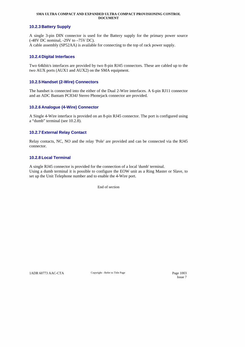
SMA ULTRA COMPACT AND EXPANDED ULTRA COMPACT PROVISIONING CONTROL DOCUMENT
1ADR 60773 AAC-CTA Copyright - Refer to Title Page Page 1003 Issue 7
10.2.3 Battery Supply
A single 3-pin DIN connector is used for the Battery supply for the primary power source (-48V DC nominal, -29V to –75V DC). A cable assembly (SP52AA) is available for connecting to the top of rack power supply.
10.2.4 Digital Interfaces
Two 64kbit/s interfaces are provided by two 8-pin RJ45 connectors. These are cabled up to the two AUX ports (AUX1 and AUX2) on the SMA equipment.
10.2.5 Handset (2-Wire) Connectors
The handset is connected into the either of the Dual 2-Wire interfaces. A 6-pin RJ11 connector and an ADC Bantam PC834J Stereo Phonejack connector are provided.
10.2.6 Analogue (4-Wire) Connector
A Single 4-Wire interface is provided on an 8-pin RJ45 connector. The port is configured using a “dumb” terminal (see 10.2.8).
10.2.7 External Relay Contact
Relay contacts, NC, NO and the relay 'Pole' are provided and can be connected via the RJ45 connector.
10.2.8 Local Terminal
A single RJ45 connector is provided for the connection of a local 'dumb' terminal. Using a dumb terminal it is possible to configure the EOW unit as a Ring Master or Slave, to set up the Unit Telephone number and to enable the 4-Wire port.
End of section

SMA ULTRA COMPACT AND EXPANDED ULTRA COMPACT PROVISIONING CONTROL DOCUMENT
1ADR 60773 AAC-CTA Copyright - Refer to Title Page Page 1101 Issue 7
11 LOCAL TERMINAL AND ELEMENT SOFTWARE
There are two main software components to the system.
One is the Network Element software containing individual software modules for each of the card types and the other is the Local Terminal management software.
During operation the Element Software is stored on a Compact Flash type System Memory device pushed into a connector on the Core/CCU card.
The purpose of the Local Terminal is to provide all the functions necessary to locally configure, control and monitor each SMA subrack. The Local Terminal comprises application software running on an IBM compatible PC interfacing to the equipment subrack via a cable. The user performs operations on the apparatus via the keyboard or mouse. Individual Compact Flash Saleable Entities are available for each release of product software. The LCT software is provided on a CD-ROM. Also contained on the CD-ROM is Network Element software to allow on-site upgrade of existing earlier releases of Compact Flash.
Each separate release of software (e.g. R3.1, R3.2 R3.3.1 etc.) will have its own unique element software build (i.e. that stored on the Compact Flash System memory device) and also LCT. It is essential for reasons of compatibility that corresponding LCT and Element software builds must be used. That is R3.2 Element Software must be used with R3.2 LCT etc.
11.1 LCT HARDWARE
Computer NH40J Next Generation LCT with Windows 2000 + Card Reader NH40K Next Generation LCT with Windows XP + Card Reader NH40F Local Craft terminal Hardware with Windows 2000 (WITHDRAWN Do Not use) NH40G Local Craft terminal Hardware with Windows XP (WITHDRAWN Do Not use) Notes:- 1) NH40F and NH40G have been superseded by NH40J and NH40K respectively. They
should not be ordered and are only shown here for reference. 2) The network element System Memory is stored on a compact Flash device in the UC & EX
product range. Maintenance upgrades of element software continue to be supported by software download. However, major updates such as a change of revision of element software can now be accomplished much faster by the direct reprogramming of the compact flash. To this end the new LCT hardware entities NH40J/NH40K come ready equipped with a ‘card reader’ to enable this reprogramming to be carried out.
3) In cases where customer already have the older NH40F/NH40G a separate stand-alone card reader is provisioned by NH40H below.
Compact Flash Programmer NH40H External USB Card Reader for use with LCT NH40F/G

SMA ULTRA COMPACT AND EXPANDED ULTRA COMPACT PROVISIONING CONTROL DOCUMENT
1ADR 60773 AAC-CTA Copyright - Refer to Title Page Page 1102 Issue 7
This is a stand-alone Compact Flash programmer that plugs into the USB port of the PC. Cables SV30J SMA1/4CP, SMA1/4c and SMA1/4UC Local Craft Terminal Cable The cable provided for the above is Belden 9502 (1WAD20028AAL) which contains 2 off twisted pairs of 24AWG PVC insulated wires with overall screen and drain wire or equivalent. It is used to connect between the PC and the RJ45 type LCT connector on the front of the SMA1/4UC.
11.2 LCT & BACKUP SOFTWARE
The Local Terminal Software is executed from the hard drive on the PC to provide the Local Terminal functions for the SMA products. The LCT software is supplied on a CD-ROM, which must first be installed onto the hard drive of the PC. The CDROM also includes backup software, of the release in question, for the actual element (i.e. the software stored in the Compact Flash device). SP81C SMA UC REL 3.1 Backup & LCT Software CD-ROM SP81CA SMA UC REL 3.2 Backup & LCT Software CD-ROM SP81CB SMA UC & EX REL 3.3.1 Backup & LCT Software CD-ROM SP81CB(1) SMA UC & EX REL 3.3.2 Backup & LCT Software CD-ROM SP81CF SMA UC & EX REL 3.4 Backup & LCT Software CD-ROM
1) R3.3.2 CD-ROM will also contain R3.3.1 software therefore SE stays the same. 2) Rel 3.3.2 & Rel 3.4 also support SMA16UC and SMA16EX products.
11.3 LCT OPERATING SYSTEM
The Operating System required for use with the Local Terminal software is Windows 2000 or Windows XP.
11.4 NETWORK ELEMENT SOFTWARE
This is stored on a Compact Flash memory device, which should be housed in the connector on the Core/CCU card. Different releases of software have different Compact Flash saleable entities. The Compact flash memory device is no longer supplied as part of any Core SE and must be ordered separately.
SP03SA SMA1/4UC Rel 3.1 Compact Flash SP03SC SMA1/4UC Rel 3.2 Compact Flash SP03SD SMA UC & EX Rel 3.3.1 Compact Flash SP03SE SMA UC & EX Rel 3.3.2 Compact Flash SP03SF SMA UC & EX Rel 3.4 Compact Flash

SMA ULTRA COMPACT AND EXPANDED ULTRA COMPACT PROVISIONING CONTROL DOCUMENT
1ADR 60773 AAC-CTA Copyright - Refer to Title Page Page 1103 Issue 7
11.5 CELLSPAN CARDS
Currently not supported on SMA UC & EX product range.
11.6 PACKETSPAN CARDS
The Packetspan software is provided on card and unit where applicable, and is programmed in the factory or by software download. Firmware is held on the card and not on the Compact Flash System Memory device. Refer to Packetspan Provisioning Control Document 03ADR00001AAF-CTA for full details.
11.7 LAYER 2 CARDS
The Layer 2 Card software is provided on card and unit where applicable, and is programmed in the factory or by software download. Firmware is held on the card and not on the Compact Flash System Memory device. Refer to Layer 2 Provisioning Control Document 05ABA00001AAL-CTA for full details.
End of section

SMA ULTRA COMPACT AND EXPANDED ULTRA COMPACT PROVISIONING CONTROL DOCUMENT
1ADR 60773 AAC-CTA Copyright - Refer to Title Page Page 1201 Issue 7
12 CARD FACIA
On those units unique to this product, facias are always fitted during manufacture. There are no options in terms of facia type or fit/not fit. Existing SMA units may or may not have options. The relevant SE structure should be consulted.
End of section

SMA ULTRA COMPACT AND EXPANDED ULTRA COMPACT PROVISIONING CONTROL DOCUMENT
1ADR 60773 AAC-CTA Copyright - Refer to Title Page Page 1301 Issue 7
13 EMC COVERS
A SMA subrack must have all card slot positions and all LTU positions fitted to maintain the EMC performance of the equipment.
13.1 UNEQUIPPED SLOT COVERS
Following the equipping of the subrack with required cards and LTUs, extra EMC covers may be needed: SP73B EMC Cover Core 1MBA62249AAB SP73C EMC Cover Comms/Aux/Ancillary 1MBA62250AAW SP73EB EMC Cover 2M Trib 1MBA62253AAD SP73DB EMC Cover 2M LTU 1MBA62252AAB SP73EA EMC Cover Generic Trib 1MBA61103ABS SP73DA EMC Cover Generic LTU 1MBA62251AAY SP73G EMC Cover EX 2M LTU Single 03MBA00068AAK SP73H EMC Cover EX 2M LTU Triple 03MBA00069AAM When any cards and/or LTUs are ordered for inclusion in the subrack and there is a core EMC cover already fitted the appropriate cover should be discarded or re-cycled. Note:- There is an EMC cover associated with the Fan slot. However, this cover (1MBA62266AAA) is provided within the SMA1/4/16UC Cores SP03AB & SP13AB.
End of section

SMA ULTRA COMPACT AND EXPANDED ULTRA COMPACT PROVISIONING CONTROL DOCUMENT
1ADR 60773 AAC-CTA Copyright - Refer to Title Page Page 1401 Issue 7
14 MECHANICAL DETAILS
The subrack is a card cage mechanical design meeting the ETSI standard ETS 300 119 Part-4 and screened for EMC according to ETSI requirements ETS 300 119 Part 2/4.
14.1 SUBRACK MOUNTING
The SMA1/4/16 UC subrack can be mounted in a number of racks:- 1. ETSI –Right hand side or Left hand side 2. 19” –Right hand side or Left hand side 3. Horizontally mounted in a ETSI rack 4. Horizontally mounted in a 19” rack 5. DIN 19 “ - Right hand side or Left hand side 6. Horizontally mounted in a DIN 19” rack If mounted vertically, 2 subracks may be fixed side by side. The 19” rack is for a standard telecomms type 19” rack which has a 600mm cabinet/535mm throat, whereas the DIN 19” meet the requirement for the German market. Options 1-4 are accommodated by the mounting brackets kit of parts 1MBB61388AAH supplied as part of the core UC system. See sections 5.1.1 & 5.1.3. Options 5-6 are accommodated by the mounting brackets kit of parts 1MBB61388BAE supplied as a separate saleable entity (SP03C) See section 5.9 If mounted horizontally then a fan unit must be fitted. Refer to Section 5.2.1.3 for full details. Note:- The brackets meet the requirements for office vibration only. They have not been tested against extended requirements for earthquake zones.
14.2 UNIT DIMENSIONS
The attached table shows the approximate dimensions of the SMA1/4UC specific units. SMA1/4UC Unit Type Height (mm) Depth (mm) Width (mm)
1HAG60627AAV SMA1/4UC SUB RACK 445 280 218 1HAT61105AAF Core/CCU Card 254 229 33 1HAT61106AAH/BAE Comms/AUX/Ancillary Card 254 229 39.5 1HAT61107AAK/ABC 64x2M Core Trib Card 254 229 22 1HBA60827AAV 32x2M Unbalanced LTU –Interface module 1HBA60828AAX 32x2M Unbalanced LTU –Front panel
147 (Combined)
117 (Combined)
71 (Combined)
1HBA60831AAX 32x2M Balanced LTU –Interface module 1HBA60832AAA 32x2M Balanced LTU –Front panel
147 (Combined)
117 (Combined)
71 (Combined)
1HAM61215AAF 3x34M LTU 147 117 21 1HAM61217AAK Power/LCT LTU (9 pin) 147 117 21 1HAM61218ABC Power/LCT LTU (3 pin) 147 117 21 1HAM61218AAM Generic Trib Power LTU 147 117 21 1HAT61114AAT Protection Core Card 254 229 33 1HAM61219AAP Fan Assembly (SMA1/4UC) 22 222 214 03HAN00007AAH AC Power & Battery Backup Unit 445 177 218 1400729-***** & 1400744-**** SFP Optical Line Module 11 13 63 1HAL60517AAW STM-1 Electrical Module DIN 1.0/2.3 11 13 63

SMA ULTRA COMPACT AND EXPANDED ULTRA COMPACT PROVISIONING CONTROL DOCUMENT
1ADR 60773 AAC-CTA Copyright - Refer to Title Page Page 1402 Issue 7
1HAM61228AAC 2 x STM-1/140M LTU 147 117 21 03HAG00001AAX EX Subrack 445 278 449 03HAM00008AAX EX Power/LCT LTU 147 117 22 03HAT00056AAQ EX 63x2M Trib Card 254 228 25 03HAM00003AAL EX 63x2M Unbal LTU 147 124 141 03HAM00002AAJ EX 21x2M Bal LTU 151 121 19 03HAT00043AAU Multirate Trib Card 254 228 25 03HAT00041AAQ STM-4/16 Core A/CCU ADM Unit 254 232 38 03HAT00041ABH STM-4/16 Core B ADM Unit 254 232 38 03HAM00009AAA EX Vertically Extended 63x2M Unbal LTU 315 124 82
14.3 WEIGHTS
Unit/Card Weights: Cards Card Weight
(kg) UC Specific 1HAG60627AAV SMA1/4UC SUB RACK 2.9 1HAT61107AAK/ABC 64x2M Core Trib Card 0.39 1HBA60827AAV 32x2M Unbalanced LTU –Interface module 0.07 1HBA60828AAX 32x2M Unbalanced LTU –Front panel 0.18 1HBA60831AAX 32x2M Balanced LTU –Interface module 0.11 1HBA60832AAA 32x2M Balanced LTU –Front panel 0.11 1HAM61217AAK Power/LCT LTU (9 pin) 0.12 1HAM61217ABC Power/LCT LTU (3 pin) 0.12 03HAN00007AAH AC Power & Battery Backup Unit (no batteries fitted) 5.2 EX Specific 03HAG00001AAX EX Subrack 7.46 03HAM00008AAX EX Power/LCT LTU 0.25 03HAT00056AAQ EX 63x2M Trib Card 0.43 03HAM00003AAL EX 63x2M Unbal LTU 0.63 03HAM00002AAJ EX 21x2M Bal LTU 0.17 03HAM00009AAA EX Vertically Extended 63x2M Unbal LTU TBC UC & EX Generic 1HAT61105AAF Core/CCU Card 0.5 1HAT61106AAH/BAE Comms/AUX/Ancillary Card 0.7 1HAM61215AAF 3x34M LTU 0.18 1HAM61218AAM Generic Trib Power LTU 0.15 1HAT61114AAT Protection Core Card 0.5 1HAM61219AAP Fan Assembly (SMA1/4UC) 0.5 1400729-***** & 1400744-**** SFP Optical Line Module 0.012 1HAL60517AAW STM-1 Electrical Module DIN 1.0/2.3 TBC 1HAM61228AAC 2 x STM-1/140M LTU TBC 03HAT00043AAU Multirate Trib Card 0.40 03HAT00041AAQ STM-4/16 Core A/CCU ADM Unit 0.80 03HAT00041ABH STM-4/16 Core B ADM Unit 0.80 SMA Generic 1HAT60622BAN 34Mbit/s Tributary Card 0.4 1HAT60623BAQ 45Mbit/s Tributary Card 0.4 1HAT60624BFE/CAP 140Mbit/s Tributary Card 0.4 1HAT60979AAC 34Mbit/s Transmux 0.42 1HAT60917AAG VCTS VCAM Card (EXTENDER I&II) 0.44 1HAT60791* STM-1 Optical Card TCM 0.46 1HAT60878AAT Dual STM-1 Optical card, without optics fitted 0.38 SN66TQ,TR,TS,TT Quad STM-1 Optical Card for SMA-1/4c 0.55 1HAT60803ABT STM-1 Electrical Card 0.4 1HAT61004ABP Dual STM-1 Electrical Card 0.38

SMA ULTRA COMPACT AND EXPANDED ULTRA COMPACT PROVISIONING CONTROL DOCUMENT
1ADR 60773 AAC-CTA Copyright - Refer to Title Page Page 1403 Issue 7
1HAT61059AAJ Quad STM-1 Electrical Card 0.45 1HAT61008*** STM-4 Optical Card TBC
14.4 RECOMMENDED RACKS FOR HOUSING SMA SUBRACKS/UNITS
Recommended ETSI racks and Racking installation kits of parts can be found in ref0.5.16 Provisioning Control Document for ETSI Rack and Associated Parts 1ADR60674AAX-CTA. NOTE: Other racks not listed may be used to house SMA Subracks but consideration should be given to the provision of suitable mounting brackets and the availability of adequate access for fibre or co-axial cables from the rack cable route to the subrack connection points. e.g. on some rack types the cable route may be blocked by the relative positions of the rack and subrack metalwork, especially important when subracks are mounted back to back.. CAUTION: The rack chosen should allow the SMA subrack to have the rack front covers fitted in normal operation, this is to provide ESD protection and assist air flow through the rack for natural convection cooling. See also Section 17 details. A fan tray should always be fitted in the SMA1/4 Ultra Compact when it is mounted horizontally. Please refer to Section 5.2.1.3 for full fan tray equipping rules.
14.5 OPTICAL FIBRE AND CABLE DRESSING
CAUTION: For racks requiring full functionality, careful consideration must be given to the management of cabling by the use of suitable cable ducting.
14.6 SUBRACK INSTALLATION
Refer to the ‘Installation Guide for SDH Transmission Equipment’ 1QDE10274AAU-YYA for further information.
End of section

SMA ULTRA COMPACT AND EXPANDED ULTRA COMPACT PROVISIONING CONTROL DOCUMENT
1ADR 60773 AAC-CTA Copyright - Refer to Title Page Page 1501 Issue 7
15 RECOMMENDED CABLES, CONNECTORS, CABLE ASSEMBLIES AND KITS OF PARTS
A number of external connection points are provided on the equipment. These give access to traffic interfaces, synchronisation ports, management ports etc. as detailed in sections 5, 6 and 7. It is important to ensure that the correct cables and connectors are used to connect to these interfaces.
15.1 RECOMMENDED CABLES
Given below is a list of recommended cables that may be used. The list is not exclusive but FAILURE to use cables of this type with comparable electrical properties may result in the installation not being fully compliant with EMC regulations. Connectors can be purchased in pre-packaged kits of parts or in the case of balanced 2M a pre-formed cable assembly is also available. (See later this section)
15.1.1 Traffic Interfaces
Card Type Cable HFE2290 BT3002 (Note1) BT2003(Note 2) ST212 (Note 1) ST214 (Note 2) RA7000 1WAE20028AAX 1WAE20002AAE 1WAE00005AAW 1WAE20031AAX 1WAE20030AAV 1300903-0035 2M Unbalanced LTU Y Y N Y N T.B.A. 34/45M LTU Y N Y N Y T.B.A. 140/155M LTU Y N Y N Y T.B.A. 140/155M Front plug up Y N Y N Y T.B.A. STM-1 Elec. SFP N N N N N Y
Notes:-
1) BT3002/ST212 not recommended for 34/45/140/155 due to increased attenuation
2) BT2003/ST214 not recommended for 2M due to its large diameter

SMA ULTRA COMPACT AND EXPANDED ULTRA COMPACT PROVISIONING CONTROL DOCUMENT
1ADR 60773 AAC-CTA Copyright - Refer to Title Page Page 1502 Issue 7
15.1.2 Non-Traffic Interfaces
Interface Type Quantity Cable Connector Type Cable Type Cable Code
Comms/Aux/Ancillary Unbalanced Sync (note 1) 2 RJ45 75 Ohm Coax 1WAE20004AAJ Aux 2 RJ45 Screened pair cable
(4pair) 1WAD20062AAJ
Balanced Sync (note1) 2 RJ45 Screened pair cable (4pair)
1WAD20062AAJ
2M Test Bus 1 RJ45 Network Management 1 RJ45 Screened pair cable
(4pair) 1WAD20062AAJ
User Output 1 9 way D-type Male User defined User defined User Input 1 15 way D-type Male User defined User defined Alarms 1 15 way D-type Female User defined User defined
UC PWR/LCT LCT cable 1 RJ45 N/A Use
1HAU62913AAF Subrack Power (9 pin LTU) 2 9 way D-type Female N/A Use
1HAU62501AAF
Subrack Power (3 pin LTU) 2 3-way Power D-type, 2 Female Contacts
N/A Use 1HAU62025AAM
EX PWR/LCT LCT cable 1 RJ45 N/A Use
1HAU62913AAF
Subrack Power 2 3-way Power D-type, 2 Female Contacts
N/A Use 1HAU62025AAM
Notes:-
1) Each of the 2 sync connectors provides access to both balanced and unbalanced sync. Wiring and choice of cable determines which interface is implemented.
Comment [JB1]: This is not acceptable. Cables need to be screened & have appropriate shielded back-shells to maintain EMC compliance!
Comment [JB2]: As above.
Comment [JB3]: As above.

SMA ULTRA COMPACT AND EXPANDED ULTRA COMPACT PROVISIONING CONTROL DOCUMENT
1ADR 60773 AAC-CTA Copyright - Refer to Title Page Page 1503 Issue 7
15.1.3 Cable Details
CABLE: HFE 2290 Cable 1 or Siemens Cable V45466-D13-C15 or V23614-A102-A76 CODE: 1WAE 20028 AAX TYPE: 75 Ohm Double Screened co-axial USE : Unbalanced connections to all Tributary ports, however the attenuation characteristics must be checked before use. NOTE: Max dist. 2M – 330m, 34M – 170m, 45M – 150m, 140M – 85m, STM-1 – 80m Note: Typical cable may support 5-10% extra length but is not guaranteed CABLE: BT 3002 Cable CODE: 1WAE 20002 AAE TYPE: 75 Ohm Double Screened co-ax to CW1383A USE : Unbalanced connections to 2M Tributary ports NOTE: Signals up to 2Mbit/s, short lengths may be acceptable above 2Mbit/s however the attenuation characteristics must be
checked before use and no EMC compliance above 2Mbits is offered by Marconi Communications (for BT) CABLE: BT 2003 Cable CODE: 1WAE 00005 AAW TYPE: 75 Ohm Double Screened co-ax (low loss) USE : Unbalanced connections to Line and Tributary ports NOTE: Signals above 2Mbit/s (for BT). Not recommended for 2M ports due to the relatively large cable diameter which
makes cable routing within the rack difficult when a large number of ports are utilised. CABLE: ST212 Cable CODE: 1WAE 20031 AAX TYPE: 75 Ohm Double Screened co-ax USE : Unbalanced connections to Tributary and Sync ports NOTE: Signals up to 2Mbit/s (for Italtel). Short lengths may be acceptable above 2Mbit/s however the attenuation
characteristics must be checked before use and no EMC compliance above 2Mbits is offered by Marconi Communications.

SMA ULTRA COMPACT AND EXPANDED ULTRA COMPACT PROVISIONING CONTROL DOCUMENT
1ADR 60773 AAC-CTA Copyright - Refer to Title Page Page 1504 Issue 7
CABLE: ST214 Cable CODE: 1WAE 20030 AAV TYPE: 75 Ohm Double Screened co-ax (low loss) USE : Unbalanced connections to Tributary/Line ports NOTE: Signals above 2Mbit/s (for Italtel). Not recommended for 2M ports due to the relatively large cable diameter which
makes cable routing within the rack difficult when a large number of ports are utilised. CABLE: Belden 9806 cable CODE: 1WAD 20062 AAJ TYPE: Screened Pair Cable (4 pair) USE : Connections to balanced Sync, Auxiliary, Alarm and Network Management ports NOTE: 100-120 Ohm balanced signals up to 2Mbit/s CABLE: Coaxial 7/0.1mm CODE: 1WAE20004AAJ TYPE: 75ohm coaxial USE : Connections to unbalanced RJ45 Sync ports. NOTE: 75 Ohm unbalanced sync signals CABLE: Raydex RA7000 cable CODE: 1300903-0035 TYPE: 75ohm coaxial USE : Connections to STM-1 SFP electrical modules.
15.2 PRE MADE CABLE ASSEMBLIES
The following standard pre-made cable assemblies have been created to ease installation.
POWER Cable Assembly – SMA1/4UC (9 pin) (SP03AA) CODE: 1HAU62501AAF TYPE: Multicore (x9) 20AWG (0.56mm2 1WAD20141AAH) terminated with 9 way D Type

SMA ULTRA COMPACT AND EXPANDED ULTRA COMPACT PROVISIONING CONTROL DOCUMENT
1ADR 60773 AAC-CTA Copyright - Refer to Title Page Page 1505 Issue 7
USE: Power cable between PWR/LCT unit (9 Way D-Type) and SMA1/4UC top of rack power supply (breakout). NOTE: 2 off required for protected battery supplies. POWER Cable Assembly – SMA1/4UC/EX (3 pin) (SP20AA) CODE: 1HAU62025AAM TYPE: Two-Core 8 AWG (4mm2 - 1WAD20128AAS) terminated with 3 pin 3W3A Power D Type USE: Power cable between PWR/LCT unit (3Way Power D-Type) & SMA1/4UC/EX top of rack power supply (breakout). NOTE: 2 off required for protected battery supplies. 2M Balanced LTU cable assembly 3m (MP93CC03) CODE: 1HAU62508AAV (3 m length) TYPE: Screened Pair Cable (32 pair) terminated with 78way sub-miniature D type USE: Connections to balanced 2M Tributary ports, NOTE: Assembly pack consists of two separate cables, each of which is terminated with a D-type at one end. This gives a total
2M balanced port connectivity of 32 channels. (i.e. 32 inputs and 32 outputs). 2M Balanced LTU cable assembly 20m (MP93CC20) CODE: 1HAU62508ABN (20m length) TYPE: Screened Pair Cable (32 pair) terminated with 78way sub-miniature D type USE: Connections to balanced 2M Tributary ports, NOTE: Assembly pack consists of two separate cables, each of which is terminated with a D-type at one end. This gives a total
2M balanced port connectivity of 32 channels. (i.e. 32 inputs and 32 outputs). CABLE: LCT Cable Assembly (SV30J) CODE: 1HAU61913AAF TYPE: Belden 9502 or equivalent, 8 way. USE: Local terminal interface for SMA1/4UC, SMA1/4CP and SMA1/4c CABLE: EOW 1U Shelf Power Cable (SP52AA) CODE: 1HAU62522AAN TYPE: 3 Core (1.5mm Sq.) CU PVC 3 x 30/0.25 SCN 16A (1WAD20122AAE) USE: Power Cabling between EOW unit and SMA1/4UC top of rack power supply

SMA ULTRA COMPACT AND EXPANDED ULTRA COMPACT PROVISIONING CONTROL DOCUMENT
1ADR 60773 AAC-CTA Copyright - Refer to Title Page Page 1506 Issue 7
15.3 CONNECTOR KITS OF PARTS
A number of kits of parts containing multiple connectors are available and these are listed below Notes:- 1. Right angled connectors are not recommended for LTU connections as the PCB connectors on the actual LTUs tend to be too close together. 2. All the traffic coax connectors listed below are of type 1.0/2.3 male. 2 are required per interface (i.e one input and one output).
Saleable Entity
Description ME Code ME Qty
SE Contents
SP53BA KOP 8 x RJ45 Plus Extractor tool (For use with e.g. Comms/Aux/Ancillary Unit.)
1MBB61427AAV 1 8 x RJ 45 Extractor tool (for extracting RJ45 connectors from the Comms/Aux/Ancillary unit)
SP53BB KOP 3 x D-Types (For use with e.g. Comms/Aux/Ancillary Unit.)
1MBB61428AAX 1 1 x 9 way D Type Male 1 x 15 way D Type Male 1 x 15 way D Type Female D-Type hoods
SU65ZA Electrical SFP Connector KOPs 1MBB61422AAK 1 2 x 45deg Male 1.0/2.3 for 7000 cable SU65ZB Electrical SFP Connector KOPs 1MBB61462AAV 1 2 x 45deg Male 1.0/2.3 for 3002 cable MP93AA Straight ST214 1 port 1MBB60851AAJ 1 2 x straight ST214 MP93BB Straight HFE2290 1 port 1MBB60891AAU 1 2 x straight HFE2290 MP93BC Straight BT2003 UK std 1 port 1MBB60912AAG 1 2 x straight BT2003 Standard MP93BD Straight BT2003 Type 43 1 port 1MBB60912BAD 1 2 x straight BT2003 Type 43 MP93BA Straight ST212 16 ports 1MBB60850AAG 2 32 x straight ST212 MP93BB Straight HFE2290 16 ports 1MBB60891ABM 2 32 x straight HFE2290 MP93BC Straight BT3002 Standard 16 ports 1MBB60913ABB 2 32 x straight BT3002 Standard MP93BD Straight BT3002 Type 43 16 ports 1MBB60913BBX 2 32 x straight BT3002 Type 43 MP93CC 78 Way D Type Belden 9806 32 port 1MBB61426AAT 1 2 x D-type
End of section

SMA ULTRA COMPACT AND EXPANDED ULTRA COMPACT PROVISIONING CONTROL DOCUMENT
1ADR 60773 AAC-CTA Copyright - Refer to Title Page Page 1601 Issue 7
16 POWER CONSUMPTION AND EQUIPMENT PROTECTION
16.1 POWER CONSUMPTION FIGURES
Figures for SMA1/4UC & EX specific cards are absolute maximums and are early estimates. See Product Champion for latest figures. Cards/Units Power
Consumption SMA1/4UC Specific 1HAG60627AAV SMA1/4UC SUB RACK 0W 1HAT61107AAK/ABC 64x2M Core Trib Card 12.5W 1HBA60827AAV 32x2M Unbalanced LTU –Interface module 0W 1HBA60828AAX 32x2M Unbalanced LTU –Front panel 0W 1HBA60831AAX 32x2M Balanced LTU –Interface module 0W 1HBA60832AAA 32x2M Balanced LTU –Front panel 0W 1HAM61217AAK Power/LCT LTU (9 pin) 0.5W 1HAM61217ABC Power/LCT LTU (3 pin) 0.5W 03HAN00007AAH AC Power & Battery Backup Unit (Maximum) TBC EX Specific 03HAG00001AAX EX Subrack 0W 03HAM00008AAX EX Power/LCT LTU 0.5W 03HAT00056AAQ EX 63x2M Trib Card 23W (inc LTU) 03HAM00003AAL EX 63x2M Unbal LTU N/A (see above) 03HAM00002AAJ EX 21x2M Bal LTU N/A (see above) 03HAM00009AAA EX Vertically Extended 63x2M Unbal LTU N/A (see above) UC & EX Generic 1HAT61105AAF Core/CCU Card (including system memory module) 19W 1HAT61106AAH/BAE Comms/AUX/Ancillary Card 12W 1HAM61215AAF 3x34M LTU 5W 1HAM61218AAM Generic Trib Power LTU 2W 1HAT61114AAT Protection Core Card 12W 1HAM61219AAP Fan Assembly (SMA1/4UC) 14W 1400729-***** & 1400744-**** SFP Optical Line Module 0.8W 4800943-0017 STM-1 Electrical Module DIN 1.0/2.3 1.0W 1HAM61228AAC 2 x STM-1/140M LTU 5.0W 03HAT00043AAU Multirate Trib Card 11W 03HAT00041AAQ STM-4/16 Core A/CCU ADM Unit 26W 03HAT00041ABH STM-4/16 Core B ADM Unit 23W SMA Generic 1HAT60622BAN 34Mbit/s Tributary Card without LTUs 12W 1HAT60623BAQ 45Mbit/s Tributary Card without LTUs 12W 1HAT60624BFE/CAP 140Mbit/s Tributary Card without LTUs 8W 1HAT60979AAC 34Mbit/s Transmux without LTU 11W 1HAT60791* STM-1 Optical Card TCM 7.7 W 1HAT60878AAT Dual STM-1 Optical Card TCM without optical modules 4 W SN66TQ,TR,TS,TT Quad STM-1 Optical Card for SMA-1/4c 12.0 W 1HAT60803ABT STM-1 Electrical Card TCM with LTU 11 W 1HAT60803ABT STM-1 Electrical Card TCM no LTU (i.e.: front access) 8.8 W 1HAT61004ABP Dual STM-1 Electrical Card with LTUs 15.4 W 1HAT61004ABP Dual STM-1 Electrical Card no LTUs (i.e.: front access) 11 W 1HAT61059AAJ Quad STM-1 Electrical Card TCM (front access only) 7.58 W 1HAT61008*** STM-4 Optical Card 8W 1HAT60876AAP Comms/Controller Card including SMC 10 W 1HAT60877AAR STM1/4 ADM Card without optics, including LTU 20 W 1HAT61052AAT STM1/4 ADM Card without optics, including LTU 20W 1HAT60988AAQ STM1/4 ADM Card without optics, including LTU 20W

SMA ULTRA COMPACT AND EXPANDED ULTRA COMPACT PROVISIONING CONTROL DOCUMENT
1ADR 60773 AAC-CTA Copyright - Refer to Title Page Page 1602 Issue 7
16.2 TYPICAL POWER CALCULATION
1 x Subrack Core* = 19.5W *Core:- Core/CCU Card, Memory module and Pwr/LCT
LTU 2 x STM1 Optical modules = 1.6W
Protection Core Card = 12W Switch protection
64x2M Trib Card = 12.5W
2 x 32x2M LTU = 0W
Dual STM1 Electrical Front access = 11W
Generic Trib Power LTU = 2W
Comms/Aux/Ancillary = 10W
68.6W
16.3 EXTERNAL PROTECTIVE DEVICE (EPD)
The EPD (fuse or circuit breaker) for each of the –48V supply feeds to the equipment should be selected as follows.
16.3.1 Type & Location
If the EPD is to be located at the top of a rack containing heat-dissipating equipment then it should be a temperature-compensated device such as a (Hydraulic) Magnetic Circuit-Breaker, or a temperature-compensated thermal or thermal-magnetic circuit-breaker. Fuses & non-compensated thermal & thermal-magnetic circuit-breakers should only be used in “end-of-suite” locations remote from racks containing heat-dissipating equipment.
16.3.2 Device Parameter Selection
The Breaking Capacity of the EPD must meet or exceed the Prospective Fault Current (IF) at its load-side terminals.
The Rated Current of the EPD should initially be selected to be the lowest available value that exceeds the rated current of the subrack internal fuse. Internal fuse data are:
• For UC: Belfuse Type SSQ-5, rated at 5A
• For EX: Belfuse Type SSQ-12, rated at 12A
• Data available at www.belfuse.com
The Rated Current of the EPD may be increased as a result of the following selection process, but should not exceed the current-carrying capacity of unprotected internal conductors in the subrack. These are:
• For UC: 16A (Power connector, 4A per contact)
• For EX: 20A (PCB Copper - via holes supplying fuse)

SMA ULTRA COMPACT AND EXPANDED ULTRA COMPACT PROVISIONING CONTROL DOCUMENT
1ADR 60773 AAC-CTA Copyright - Refer to Title Page Page 1603 Issue 7
The time-current characteristic should now be selected to meet the following criteria:
• The minimum energy let-through (I2t) of the EPD must be greater than the I2t value represented by the equivalent time or current point of the inrush current limit curve given in ETSI EN 300 132-2 Clause 4.7.1 & Figure 2 (see www.etsi.org), for all values of I and t.
For the purpose of this comparison the maximum input current Im as defined in EN 300 132-2 is given by:
48 . (min)
(max)R
Rm
VII = . . . . [1]
Where IR(max) & VR(min) are the maximum RATED CURRENT and minimum RATED VOTAGE of the subrack, as given on the rating label & below:
VR(min) = 38.4V
For UC: IR(max) = 4A, ⇒ Im = 3.2A
For EX: IR(max) = 9.5A, ⇒ Im = 7.6A
• The minimum energy let-through (I2t) of the EPD must be greater than the maximum energy let-through of the subrack internal fuse for any given value of I where I is less-than or equal-to the Prospective Fault Current (IAN) at the Power-LTU power connector, given that where the power cord has N conductors per supply pole (i.e. in the UC power cord), all such conductors are sound & the fault current is shared between them.
• If the EPD is a Fuse then it must be further co-ordinated with the subrack internal fuse so that the EPD is not weakened if the internal fuse operates.
• The guaranteed maximum disconnect-times of the EPD at IF, IA & at IAN must be capable of protecting the Power Cord, where IA & IAN are the Prospective Fault Currents at the Power-LTU power connector when one or N conductors respectively per supply pole carry the fault current. NOTE: for power cords where N ≠ 1, IA assumes that a single conductor carries the fault current in one pole, but all N conductors carry the fault current in the other pole.
This is not expected to be a problem when using the cables recommended in section 15.2 provided that the fastest time-current characteristic that meets all of the above criteria has been selected.
Power Cord protection can be assessed using Equation 2 for faults anywhere within the Power Cord (desirable) & Equation 3 for equipment faults (mandatory). Meeting Equation 3 with N = 1 (IAN = IA) protects the power cord against faults within its own connector.
2
22 .5F
F ISkT ≤≥ . . . . [2] 2
222 ..5AN
AN INSkT ≤≥ . . . . [3]
TF / TAN = disconnect-time of EPD in seconds at IF / IAN respectively. Tx must be less than 5 seconds for formula to be valid: typical values are 1 - 30 ms.

SMA ULTRA COMPACT AND EXPANDED ULTRA COMPACT PROVISIONING CONTROL DOCUMENT
1ADR 60773 AAC-CTA Copyright - Refer to Title Page Page 1604 Issue 7
k = Cable Factor. This is normally obtained from local Building Wiring Regulations in the territory of installation, or from the cable manufacturer. For example, in the UK BS 7671 gives a value of k = 100 for 90°C PVC cables with conductors operating at maximum temperature (i.e. carrying the cable’s rated current taking into account ambient temperature de-rating factors).
S = Cross-sectional area of an individual power cord conductor in mm2
N = Number of conductors per supply pole - (4 for UC, 1 for EX)
IF / IAN = Prospective Fault Current at EPD / Power-LTU power connector
16.4 MULTIPLE SUBRACK MOUNTING
16.4.1 Mechanical considerations
The subrack may be mounted in either the vertical or horizontal axis. In the vertical mounting option multiple subracks can be mounted in the vertical direction and up to 2 side by side horizontally. However, when doing so thermal aspects must be considered as described in the following section. The standard Core UC subracks (SP03AB & SP13AB) comes supplied with brackets to allow all these mounting options. For horizontal mounting a fan must always be fitted. Please refer to Section 5.2.1.3 for full fan tray equipping rules. Note:- The brackets meet the requirements for office vibration only. They have not been tested against extended requirements for earthquake zones.
16.4.2 Thermal Considerations
If required, it is permissible to mount more than one SMA subrack or other equipment in one Rack framework, however consideration must be given to: a) The maximum permissible power dissipation allowed in the customer’s rack framework. b) The maximum rise in temperature under which the upper SMA subrack will operate. c) The ETS Climatic Limits. The equipment has been tested as conformant to ETS 300 019-2
Class 3.1e, which includes a working range of time operating at different temperatures and relative humidities.
d) The reduced MTBF resulting from continuous operation at elevated temperature. e) Forced air-cooling. Guide to compliance: It is considered that with a maximum overall sub-rack power dissipation within a 19inch or ETSI rack framework of up to 780W, the expected temperature rise over outside rack framework ambient would be no greater than 20DegC. This would be seen as the limit for rack equipping. Refer to important notes below:-

SMA ULTRA COMPACT AND EXPANDED ULTRA COMPACT PROVISIONING CONTROL DOCUMENT
1ADR 60773 AAC-CTA Copyright - Refer to Title Page Page 1605 Issue 7
NOTE: Continuous operation at maximum ambient temperature is not recommended, it would be expected that continuous operation would be at ambient temperatures less than 30DegC but operation up to the maximum is allowable for short periods (Hours) as part of a weather or air conditioning plant failure – see c) above. NOTE: Operating a subrack in increased ambient temperature as normal deployment will reduce the Equipment MBTF. THE COMBINED POWER DISSIPATION OF ALL EQUIPMENT IN A RACK SHOULD BE CHECKED AGAINST MARCONI COMMUNICATIONS AND CUSTOMER INSTALLATION RULES. The use of multiple subracks with total power dissipation exceeding 780W should not normally be used without forced air cooling or further environmental verification. Note: If the subrack is mounted horizontally then a fan tray should always be fitted. Please refer to Section 5.2.1.3 for full fan tray equipping rules.
End of section

SMA1/4/16 UC & EX - PROVISIONING CONTROL DOCUMENT
1ADR 60773 AAC-CTA Copyright - Refer to Title Page Page 1701 Issue 7
17 RELIABILITY
17.1 SMA CARD MTBF PREDICTIONS
The following card figures are to be assumed for MTBF calculations. Engineering should be consulted before any figures other than the MTBF (Spec.) are committed to a customer. Note :- MTBF (Spec.) = MTBF(HRD*) x 3 and may be offered to customers as the Marconi Communications specification for MTBF. This multiplication factor is based on passed experience of previous units calculated versus actual MTBF. Cards have MTBF calculated to HRD5 however some cards from early equipment were calculated to HRD4. It should be emphasised that the figures below are from theoretical calculations only and are not based on actual field returns. Also the figures for the SMA1/4UC & EX specific MEs should be treated with caution. Note 1) These particular figures are rough estimates based on similar units and are not from detailed calculations. Note 2) Figure given is for the combined Interface and front panel unit, which together form the LTU function.
Cards/Units MTBF years HRD(*)
MTBF years (Spec.)
SMA1/4UC Specific (Estimates based on current designs) 1HAG60627AAV SMA1/4UC SUB RACK module (Note 1) 100 300 1HAT61107AAK/ABC 64x2M Core Trib Card 20 60 1HBA60827AAV 32x2M Unbalanced LTU –Interface module (Note 2) 131.3 393.9 1HBA60828AAX 32x2M Unbalanced LTU –Front panel - - 1HBA60831AAX 32x2M Balanced LTU –Interface module (Note 2) 138.88 416.64 1HBA60832AAA 32x2M Balanced LTU –Front panel - - 1HAM61217AAK Power/LCT LTU (9 pin) (Note 1) 100 300 1HAM61217ABC Power/LCT LTU (3 pin) (Note 1) 100 300 03HAN00007AAH AC Power & Battery Backup Unit TBC TBC EX Specific 03HAG00001AAX EX Subrack 81 243 03HAM00008AAX EX Power/LCT LTU 640 640 03HAT00056AAQ EX 63x2M Trib Card 14.1 42.3 03HAM00003AAL EX 63x2M Unbal LTU 9.5 28.5 03HAM00002AAJ EX 21x2M Bal LTU 42.2 126.2 03HAM00009AAA EX Vertically Extended 63x2M Unbal LTU 9.5 28.5 UC & EX Generic 1HAT61105AAF Core/CCU Card 15.43 46.29 1HAT61106AAH/BAE COMMS/AUX/Ancillary Card (Note 1) 20 60 1HAM61215AAF 3x34M LTU (Note 1) 50 150 1HAM61218AAM Generic Trib Power LTU 50.0 150.0 1HAT61114AAT Protection Core Card 21.06 63.18 1HAM61219AAP Fan Assembly (SMA1/4UC) TBC TBC 1400729-***** & 1400744-**** SFP Optical Line Module 50 150 1HAL60517AAW STM-1 Electrical Module DIN 1.0/2.3 860.47 2581.41 1HAM61228AAC 2 x STM-1/140M LTU 29.4 88.2 03HAT00043AAU Multirate Trib Card 45 135 03HAT00041AAQ STM-4/16 Core A/CCU ADM Unit 13.5 40.5 03HAT00041ABH STM-4/16 Core B ADM Unit 22.5 67.5

SMA ULTRA COMPACT AND EXPANDED ULTRA COMPACT PROVISIONING CONTROL DOCUMENT
1ADR 60773 AAC-CTA Copyright - Refer to Title Page Page 1702 Issue 7
Cards/Units MTBF years HRD(*)
MTBF years (Spec.)
SMA Generic (Calculated figures) 1HAT60791* STM-1 Optical Card TCM 20 60 1HAT60878AAT Dual STM-1 Optical Card without optical modules 21.69 65.07 SN66TQ,TR,TS,TT Quad STM-1Optical Card for SMA-1/4c 25.16 75.48 1HAT60803ABT STM-1 Electrical Card TCM 21.1 63.3 1HAT61004ABP Dual STM-1Electrical Card 18.25 54.75 1HAT61059AAJ Quad STM-1Electrical Card TCM 40.15 120.45 1HAT61008*** STM-4 Optical Card 1HAT60874* STM1 Dual Fibre Working Optical Module 28.1 84.3 1HAT61098* STM1 Dual Fibre Working Optical Module 28.1 84.3 1HAT60908* STM4 Dual Fibre Working Optical Module 28.1 84.3 1HAT60875* STM1 Single Fibre Working Optical Module 28.1 84.3 1HAT60909* STM4 Single Fibre Working Optical Module 28.1 84.3 1HAT60624BFE/CAP 140Mbit/s Tributary Card 35 105 1HAM60798ABN/ACF/839AAN 140Mbit/s/STM-1 LTU & Link LTU 111 333 1HAT60622BAN/623BAQ 34/45Mbit/s Tributary Card 34 102 1HAT60979AAC 34M Transmux Card TBD TBD
End of section

SMA ULTRA COMPACT AND EXPANDED ULTRA COMPACT PROVISIONING CONTROL DOCUMENT
1ADR 60773 AAC-CTA Copyright - Refer to Title Page Page 1801 Issue 7
18 STANDARDS AND APPROVALS
Note: This section needs approval from SDA and Engineering. Discuss with Product Champion before making any commitments to customers etc. The SMA-1/4UC & EX equipment meets the following specifications when all EMC and protective equipment rack covers are in position. Consideration should be given to the expected working conditions of the equipment when installed in an equipment rack, see Section 14 & 16 for guidance. Electrical, Environmental and Safety Approval Testing has been performed considering: The SMA-1/4UC equipment is primarily rack-mounted equipment for use in telecomms centres. Approved racks are described in Section 14.4. The equipment is not approved for use in environments beyond the environmental specification. If alternative housing is required then the necessary advice and approval shall be sought from the design authority and where necessary testing will be required. 18.1 ENVIRONMENTAL SPECIFICATION
Atmospheric Equipment meets ETS 300 019-2 In operation - Class 3.1E In Storage - Class 1.1 In transport - Class 2.3 Electromagnetic
Product Family Standard EN 300 386-2 and European Standards
ES 201 468 Enhanced Availability of Service Level 2 including, but not limited to: Radiated Immunity - EN 61000-4-3 (10V/m) Radiated Emission - EN 55022 (Class B) DC Power Interface - ETS 300 132-2 and British Telecommunications
Requirements for telecommunication power requirements – BTR 2511 Iss03
18.2 SAFETY
In order to comply with the safety requirements of EN60950, the equipment should be professionally installed in a restricted access location.

SMA ULTRA COMPACT AND EXPANDED ULTRA COMPACT PROVISIONING CONTROL DOCUMENT
1ADR 60773 AAC-CTA Copyright - Refer to Title Page Page 1802 Issue 7
Note: A protective earth connection must be made: Before any external cables are connected, the equipment must be connected to Protective Earth: The SMA1/4UC & EX shelf-frame shall be connected to protective earth via the shelf support metalwork. The frame must remain connected to Protective Earth until all external cables are removed. Cards must not be removed or inserted with cables attached. The equipment has been designed to meet the general requirements of:- Health and Safety at Work Act 1974 EN 60950 BT Specification RC5000P Marconi Communications Product Safety Design Guide 1QDA 20090 AAY-YYA.
18.2.1 Electrical Safety
The equipment meets EN60950: 2000
AS/NZS60950: 2000 ACA TS 001: 1997
18.2.2 Optical Safety
The optical source devices which are used in this equipment may have been classified by their manufacturers, under laser radiation safety standards EN 60825-1, as class 3M laser products, and so potentially can emit invisible optical radiation in excess of the inherently safe class 1 limits defined by this standard. The use of these optical devices within the equipment, however, involves drive, power monitoring and control circuitry to limit the power available from these devices, the design and setting up of the equipment ensures that the product meets the class 1 limits. No attempt should be made to adjust or tamper with the laser or its control circuitry as this may result in class 1 emission limits being exceeded. A safety interlock/shutdown mechanism is provided, which limits the emission duration of the transmitted output power to a maximum of 4.6 seconds in the event of a fibre breakage. Two discrete control loops are provided to ensure that the output power cannot exceed its specified operating limits. In the event of a fault occurring, these loops remove power from the laser drive circuitry. Refer to the SMA Handbook warnings and operating instructions for guidance on laser and other hazards.
18.3 REPORTS
Reports have been produced to support the compliance and approval of the SMA equipment (e.g. Thermal Analysis /Environmental/EMC/Safety Reports).
End of section
END OF DOCUMENT