Comparison of In-Plane and Out-of-Plane Failure Modes of ...
36
This is a pre-print version of an article published in Engineering Structures. Pulatsu, B., Erdogmus, E., & Lourenço, P. B. (2019). Comparison of in-plane and out-of-plane failure modes of masonry arch bridges using discontinuum analysis. Engineering Structures, 178, 24-36. 1 Comparison of In-Plane and Out-of-Plane Failure Modes of Masonry Arch Bridges using Discontinuum Analysis Bora Pulatsu 1 , Ece Erdogmus 2 , and Paulo B. Lourenço 3 Abstract: This research aims to provide a better understanding of the structural behavior of masonry arch bridges using advanced modeling strategies. Two main contributions are achieved in this article; first, triggering mechanisms for the out of plane failure of spandrel walls are established; second, the influence of soil backfill on the behavior and strength of the bridges is presented through a comprehensive parametric study. Here, masonry arch bridges are modeled using a discontinuum approach, composed of discrete blocks, including also a continuum mesh to replicate infill material, adopting a framework of discrete element modeling. The equations of motion for each block are solved by an explicit finite-difference method, using the commercial software 3DEC. The results of the preliminary analyses are compared with analytical solutions and limit state analysis for validation purposes. Different arch bridge models, representing common geometrical properties in the northwest Iberian Peninsula are analyzed. Transverse effects, damage patterns and collapse mechanisms are discussed under different types of loading. The analysis demonstrated the severe capacity reduction due to spandrel wall failures and the importance of soil backfill in results, only possible by taking advantage of the performed numerical modeling strategy. 1 PhD Candidate, Durham School of Architectural Engineering and Construction, University of Nebraska- Lincoln, Nebraska, United States, [email protected] 2 Professor, Durham School of Architectural Engineering and Construction, University of Nebraska- Lincoln, Nebraska, United States, [email protected] 3 Professor, ISISE, Department of Civil Engineering. University of Minho, Guimaraes, Portugal, [email protected]
Transcript of Comparison of In-Plane and Out-of-Plane Failure Modes of ...

This is a pre-print version of an article published in Engineering Structures. Pulatsu, B., Erdogmus, E., & Lourenço, P. B. (2019). Comparison of in-plane and out-of-plane failure modes of masonry arch bridges using discontinuum analysis. Engineering Structures, 178, 24-36.
1
Comparison of In-Plane and Out-of-Plane Failure Modes of Masonry
Arch Bridges using Discontinuum Analysis
Bora Pulatsu1, Ece Erdogmus2, and Paulo B. Lourenço3
Abstract: This research aims to provide a better understanding of the structural behavior
of masonry arch bridges using advanced modeling strategies. Two main contributions are
achieved in this article; first, triggering mechanisms for the out of plane failure of spandrel
walls are established; second, the influence of soil backfill on the behavior and strength
of the bridges is presented through a comprehensive parametric study. Here, masonry
arch bridges are modeled using a discontinuum approach, composed of discrete blocks,
including also a continuum mesh to replicate infill material, adopting a framework of
discrete element modeling. The equations of motion for each block are solved by an
explicit finite-difference method, using the commercial software 3DEC. The results of the
preliminary analyses are compared with analytical solutions and limit state analysis for
validation purposes. Different arch bridge models, representing common geometrical
properties in the northwest Iberian Peninsula are analyzed. Transverse effects, damage
patterns and collapse mechanisms are discussed under different types of loading. The
analysis demonstrated the severe capacity reduction due to spandrel wall failures and the
importance of soil backfill in results, only possible by taking advantage of the performed
numerical modeling strategy.
1 PhD Candidate, Durham School of Architectural Engineering and Construction, University of Nebraska-Lincoln, Nebraska, United States, [email protected]
2 Professor, Durham School of Architectural Engineering and Construction, University of Nebraska-Lincoln, Nebraska, United States, [email protected]
3 Professor, ISISE, Department of Civil Engineering. University of Minho, Guimaraes, Portugal, [email protected]

This is a pre-print version of an article published in Engineering Structures. Pulatsu, B., Erdogmus, E., & Lourenço, P. B. (2019). Comparison of in-plane and out-of-plane failure modes of masonry arch bridges using discontinuum analysis. Engineering Structures, 178, 24-36.
2
1 Introduction
Masonry arch bridges constitute an important asset of the transportation
infrastructure not only in Europe but also in northeastern United States [1]. Although,
newer construction materials, such as steel or reinforced concrete, became more popular
in the construction sector after the mid-20th century, stone and brick masonry bridges still
continue to make a remarkable contribution to world’s infrastructure. For instance,
masonry arch bridges constitute around 40% of the bridge stock in Europe [2]. In United
States, there are 1700 masonry bridges, according to the 2013 National Bridge Inventory
(NBI) [3]. Given that the majority of these bridges are older than 100 years [4], they may
suffer from material deterioration, lack of maintenance, increased axle loads and high
volume of traffic through the decades.
Notwithstanding, a remarkable portion of masonry bridges still constitute the heritage
of transportation system in many countries. Therefore, preserving their structural integrity
has a critical importance due to their historical significance. On the other hand, it has been
a challenge for engineers to analyze masonry arch bridges because there are no widely
adopted structural analysis procedures, and true understanding of their complex behavior
requires nonlinear analysis. Furthermore, there are numerous parameters affecting the
strength, stiffness and overall collapse mechanism of masonry bridges such as: boundary
conditions, backfill properties, span, rise and arch thickness among others.
In this research, a vulnerable local failure mechanism, namely spandrel wall collapse,
and global failure mode of arch barrel are investigated. In addition, a parametric study is
performed on the backfill properties and the obtained results are compared with a
simplified approach. The capacity and the transverse failure of spandrel walls are
simulated by means of three-dimensional mixed discrete-continuum approach.

This is a pre-print version of an article published in Engineering Structures. Pulatsu, B., Erdogmus, E., & Lourenço, P. B. (2019). Comparison of in-plane and out-of-plane failure modes of masonry arch bridges using discontinuum analysis. Engineering Structures, 178, 24-36.
3
2 Background on Numerical Analysis of Masonry Arch
Structures
It is in the last few decades that advances in computer science and engineering made
it possible to implement numerical methods to solve the governing differential equations.
Briefly, numerical modelling of masonry structures may be examined under two main
categories: continuum and discontinuum approaches.
2.1 Continuum based models
In continuum models, the properties of masonry components (units and mortar) are
averaged and an equivalent homogeneous medium is generated. Therefore, an averaged
constitutive relationship is required to use in the numerical model. The continuum
parameters may be determined from experimental tests, but specimens should have a
reasonably large scale to yield homogeneous state of stress, or homogenization
techniques [5]. The finite element method (FEM) is one of the most common numerical
modeling strategies employed in continuum-based models, i.e. macro modeling
approach, with different levels of complexity.
The least complicated way to model a masonry arch may be achieved via one-
dimensional beam-type elements implemented into the framework of traditional finite
element procedure. Boothby [6] used frame elements to perform load rating for different
bridges and validated his linear elastic solution via field tests. Furthermore, the elastic
perfectly plastic in compression and no tensile resistant (NTR) material model for
masonry was used by Brencich and De Francesco [7] and an iterative procedure was
implemented to adjust the effective height of the arch without allowing tensile stresses.
They applied the same procedure on multi span masonry arch bridges and validated the
results via experimental studies from the literature [8]. Moreover, dynamic behavior of
masonry arches and arch bridges were investigated using a fiber beam approach in which
effective material properties are taken into account [9]. Although, one dimensional models
simplify the problem and neglect the complex fill-structure interaction, they have a strong
advantage in terms of computational cost compared with two and three-dimensional
models.

This is a pre-print version of an article published in Engineering Structures. Pulatsu, B., Erdogmus, E., & Lourenço, P. B. (2019). Comparison of in-plane and out-of-plane failure modes of masonry arch bridges using discontinuum analysis. Engineering Structures, 178, 24-36.
4
Backfill material may be represented in two dimensional models by explicitly
incorporating an elastoplastic constitutive law for the soil [10]. Additionally, to introduce
discontinuities at the joints, unilateral contact interfaces may be used in the arch, which
allow to obtain joint openings, cracks and sliding failure [11]. However, 2D simulations do
not provide information about transverse direction since the numerical model is generally
taken as a symmetric cross section with respect to span direction. Hence, they may not
represent inherent three-dimensional response of masonry arch structures [12]. On the
other hand, three-dimensional models capture the full structural response and local
failures, such as spandrel wall collapse and skew arch bridge behavior. Fanning and
Boothby [13] introduced a three-dimensional nonlinear finite element analysis to predict
the stone arch bridge behavior by comparing the results of full-scale field test on existing
bridges. They emphasized the importance of three-dimensional effects and highlighted
the relative deflection (sliding or movement) between backfill and masonry system (arch
barrel and spandrel wall). Furthermore, Conde et al. [14] noted critical transverse effects
while assessing the load carrying capacity of Vilanova Bridge. Hence, the importance of
soil backfill on the transverse effects of masonry arch bridges have been stated by
researchers and noticeable effort has been spent to simulate this complex behavior via
numerical solutions.
2.2 Discontinuum Modeling
The traditional continuum-based calculation techniques, usually FEM based, are not
able to reflect the complex mechanical interaction of materials or structures consisting of
discontinuous system, i.e. dry joint masonry structures, unless interface elements are not
considered [15,16]. The discrete element method (DEM) provides a naturally
discontinuous medium where complex mechanical interaction of distinct blocks can be
simulated. Masonry construction, consisting of stiff units (stone or brick) and weak-or no
mortar joints, fits the formulation of DEM which provides quite realistic simulations in
terms of failure mechanism. Thus, discontinuum idealization provides significant
advantages to model complex structures, which may experience complete block
separation and large movements [17]. Depending on the complexity of the problem and
accuracy needed, large number of discrete blocks can be used to represent each
This is a pre-print version of an article published in Engineering Structures. Pulatsu, B., Erdogmus, E., & Lourenço, P. B. (2019). Comparison of in-plane and out-of-plane failure modes of masonry arch bridges using discontinuum analysis. Engineering Structures, 178, 24-36.
5
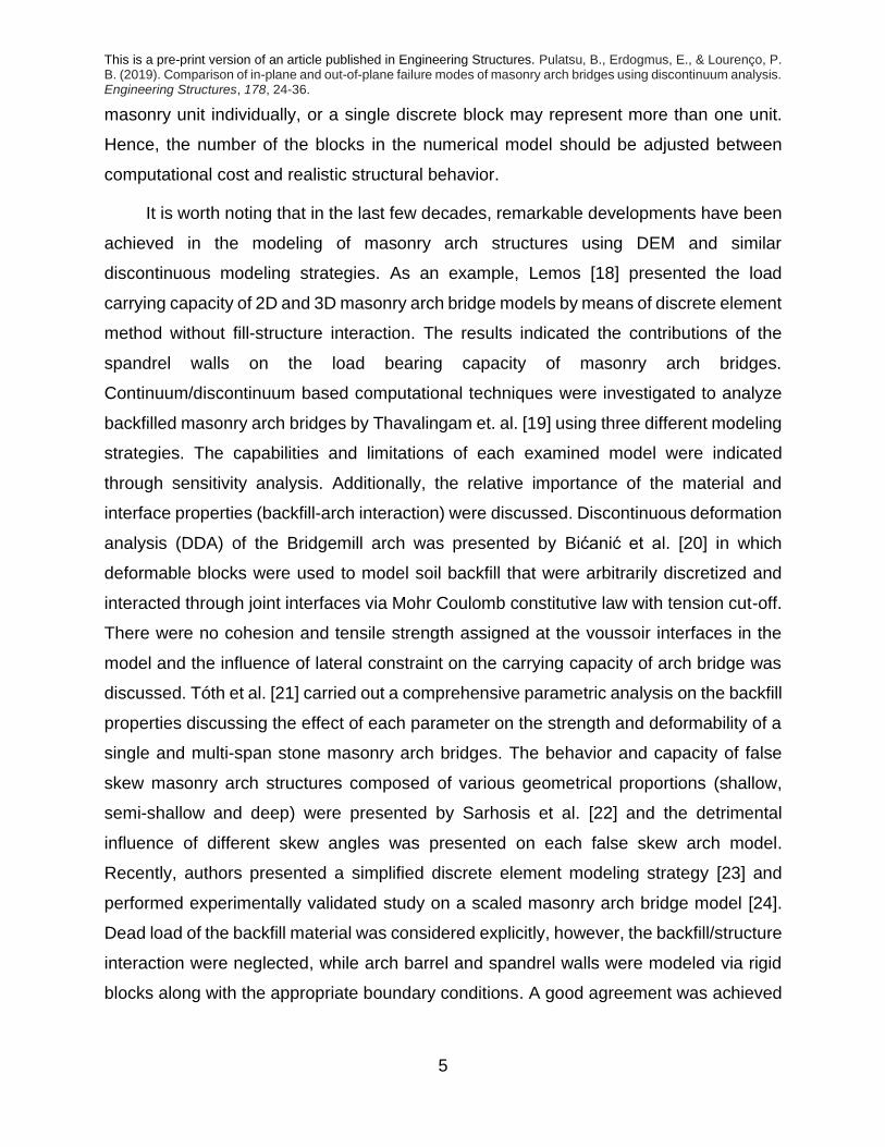
masonry unit individually, or a single discrete block may represent more than one unit.
Hence, the number of the blocks in the numerical model should be adjusted between
computational cost and realistic structural behavior.
It is worth noting that in the last few decades, remarkable developments have been
achieved in the modeling of masonry arch structures using DEM and similar
discontinuous modeling strategies. As an example, Lemos [18] presented the load
carrying capacity of 2D and 3D masonry arch bridge models by means of discrete element
method without fill-structure interaction. The results indicated the contributions of the
spandrel walls on the load bearing capacity of masonry arch bridges.
Continuum/discontinuum based computational techniques were investigated to analyze
backfilled masonry arch bridges by Thavalingam et. al. [19] using three different modeling
strategies. The capabilities and limitations of each examined model were indicated
through sensitivity analysis. Additionally, the relative importance of the material and
interface properties (backfill-arch interaction) were discussed. Discontinuous deformation
analysis (DDA) of the Bridgemill arch was presented by Bićanić et al. [20] in which
deformable blocks were used to model soil backfill that were arbitrarily discretized and
interacted through joint interfaces via Mohr Coulomb constitutive law with tension cut-off.
There were no cohesion and tensile strength assigned at the voussoir interfaces in the
model and the influence of lateral constraint on the carrying capacity of arch bridge was
discussed. Tóth et al. [21] carried out a comprehensive parametric analysis on the backfill
properties discussing the effect of each parameter on the strength and deformability of a
single and multi-span stone masonry arch bridges. The behavior and capacity of false
skew masonry arch structures composed of various geometrical proportions (shallow,
semi-shallow and deep) were presented by Sarhosis et al. [22] and the detrimental
influence of different skew angles was presented on each false skew arch model.
Recently, authors presented a simplified discrete element modeling strategy [23] and
performed experimentally validated study on a scaled masonry arch bridge model [24].
Dead load of the backfill material was considered explicitly, however, the backfill/structure
interaction were neglected, while arch barrel and spandrel walls were modeled via rigid
blocks along with the appropriate boundary conditions. A good agreement was achieved

This is a pre-print version of an article published in Engineering Structures. Pulatsu, B., Erdogmus, E., & Lourenço, P. B. (2019). Comparison of in-plane and out-of-plane failure modes of masonry arch bridges using discontinuum analysis. Engineering Structures, 178, 24-36.
6
between the numerical model and the experimental study, in terms of collapse
mechanism and load carrying capacity.
2.3 Theoretical Background of DEM
According to Cundall and Hart [25], one discrete element code should provide
several features, namely: i) the possibility to simulate large displacement, rotation and
sliding failure of individual blocks; ii) automatic contact detection. Further information on
contact detection algorithm for polyhedral blocks can be found in [26].
In present research, each masonry unit is considered as a rigid block with six
degrees of freedom (3 rotational and 3 translational). The discontinuous system of blocks
has mechanical interaction acting through their sub-contacts with each other where the
interface forces develop and are updated according to the assigned failure criteria. The
elastic normal and shear force increments are calculated as given in Equation 1 and 2,
respectively.
𝛥𝐹𝑛 = 𝑘𝑁 𝛥𝑈𝑁𝐴𝐶 (1)
𝛥𝐹𝑠 = 𝑘𝑆 𝛥𝑈𝑆𝐴𝐶 (2)
where, 𝑘𝑁 , 𝑘𝑆 and 𝐴𝐶 are the stiffness in the normal direction, stiffness in shear direction
and the area of sub-contact. Furthermore, 𝛥𝐹𝑛, 𝛥𝐹𝑠 , 𝛥𝑈𝑁 and 𝛥𝑈𝑆 indicate the resultant
normal force, resultant shear force, normal and shear displacement increments,
respectively. Once the force increments are calculated, the total normal and shear force
vectors are updated.
The obtained contact forces are adjusted according to the assigned contact
constitutive model. In this research, the contact normal force is limited by the tensile
strength 𝑓𝑇 as given in Equation 3. Moreover, in shear the direction, Coulomb-slip joint
model is utilized, and shear forces are limited according to Equation 4.
𝐹𝑛 ≤ 𝑓𝑇 𝐴𝐶 (3)

This is a pre-print version of an article published in Engineering Structures. Pulatsu, B., Erdogmus, E., & Lourenço, P. B. (2019). Comparison of in-plane and out-of-plane failure modes of masonry arch bridges using discontinuum analysis. Engineering Structures, 178, 24-36.
7
𝐹𝑠 ≤ 𝑐 𝐴𝐶 + 𝐹𝑛 𝑡𝑎𝑛𝜙 (4)
where, 𝑐 and 𝜙 are the joint cohesion and friction angle, respectively. A brittle contact
model is assumed at the joints by setting the tensile strength and cohesion to zero onset
of failure.
The governing translational and rotational differential equations for rigid blocks are
solved explicitly at each time-step and the constitutive equations are applied. First, the
equations of translational motion for a single block is given in Equation 5.
�̈�𝑖 + 𝛼�̇�𝑖 =
𝛴𝐹𝑖
𝑚𝑖+ 𝑔𝑖 (5)
where, �̈�, 𝑥,̇ 𝛼, 𝑚 and 𝑔𝑖 are the acceleration of the block centroid, the velocity of the block
centroid, the viscous damping constant, the block mass and the gravity acceleration
vector, respectively. The sum of forces acting on a block is indicated as 𝛴𝐹 which includes
contact and external forces. In addition, the simplified rotational equation of motion is
presented in Equation 6.
�̇�𝑖 + 𝛼𝜔𝑖 =
𝛴𝑀𝑖
𝐼 (6)
where 𝜔, 𝐼 and 𝛴𝑀 represent the angular velocity, moment of inertia and total torque. The
given equations of motion are integrated by a central difference procedure, in which
translational and rotational velocities are calculated. The time step, 𝑡, is divided into mid
intervals and next time step 𝑡 + 𝛥𝑡
2 is represented as 𝑡+ and the previous time step 𝑡 −
𝛥𝑡
2
is indicated as 𝑡−. Once, the velocities are obtained for the centroid of a rigid block,
translational and rotational increments are calculated. Accordingly, the positions of the
blocks are updated. Then, contact-displacement increments are employed in the next
time step to calculate the new contact forces using the force-displacement law.
A similar numerical procedure is performed for the backfill material, however, in
this case, a continuum deformable block is considered, which is internally discretized into
tetrahedral elements interacting with its surrounding, i.e. arch barrel and spandrel walls,
at the boundary surfaces through contact points. Note that vertices of the tetrahedral

This is a pre-print version of an article published in Engineering Structures. Pulatsu, B., Erdogmus, E., & Lourenço, P. B. (2019). Comparison of in-plane and out-of-plane failure modes of masonry arch bridges using discontinuum analysis. Engineering Structures, 178, 24-36.
8
elements are referred as gridpoints, whereas tetrahedral elements are designated as
zones. The deformation of the continuous deformable block is described by the nodal
displacements. Hence, velocities at the gridpoints may be calculated as
�̇�𝑖(𝑡+) = �̇�𝑖(𝑡−) +
𝛥𝑡
𝑚𝑛
{𝛴𝐹𝑖𝑡 − (𝐹𝑑)𝑖} (7)
𝛴𝐹𝑖 = 𝐹𝑔𝑟𝑎𝑣𝑖𝑡𝑦 + 𝐹𝑐𝑜𝑛𝑡𝑎𝑐𝑡 + 𝐹𝑒𝑥𝑡𝑒𝑟𝑛𝑎𝑙 + 𝐹𝑖𝑛𝑡𝑒𝑟𝑛𝑎𝑙 (8)
(𝐹𝑑)𝑖 = 𝛼|𝛴𝐹𝑖𝑡| sgn(�̇�𝑖(𝑡−)) (9)
where 𝑚𝑛, 𝛴𝐹𝑖 and 𝐹𝑑 are the nodal mass, the total nodal force vector calculated at each
gridpoint and the damping force. The total force vector includes gravity forces 𝐹𝑔𝑟𝑎𝑣𝑖𝑡𝑦,
sub-contact forces 𝐹𝑐𝑜𝑛𝑡𝑎𝑐𝑡, external applied loads 𝐹𝑒𝑥𝑡𝑒𝑟𝑛𝑎𝑙, and contribution to the
internal stresses in the zones adjacent to the grid point 𝐹𝑖𝑛𝑡𝑒𝑟𝑛𝑎𝑙, obtained as
𝐹𝑖𝑛𝑡𝑒𝑟𝑛𝑎𝑙 = ∫𝜎𝑖𝑗𝑛𝑗𝑑𝑠
𝑆
(10)
where, 𝑛𝑗 stands for the normal to the surface and 𝜎𝑖𝑗 indicates the zone stress tensor.
The Mohr-Coulomb yield criterion is used for the zones and stress tensors are
updated in the framework of an explicit dynamic-solution scheme. For each time step,
elastic trial (or guess) stresses are calculated using principal stresses (𝜎1, 𝜎2, 𝜎3) and
strain increments (∆𝜀1, ∆𝜀2, ∆𝜀3) (one example is given in Equation 11, while the rest can
be obtained by a rotation of indices in the stress and strain components) and checked
against composite failure criterion.
𝜎1𝑖+1 = 𝜎1
𝑖 + 𝛼1 𝛥𝜀1 + 𝛼2 (𝛥𝜀2 + 𝛥𝜀3) (11)

This is a pre-print version of an article published in Engineering Structures. Pulatsu, B., Erdogmus, E., & Lourenço, P. B. (2019). Comparison of in-plane and out-of-plane failure modes of masonry arch bridges using discontinuum analysis. Engineering Structures, 178, 24-36.
9
where, 𝛼1 and 𝛼2 are equal to 𝐾 + 4𝐺 3⁄ and 𝐾 − 2𝐺 3⁄ , in which 𝐾 and 𝐺 indicate bulk
and shear modulus. The stress states that belong to the next time step is demonstrated
using the superscripts, 𝑖+1.
Mohr-Coulomb model with a Rankine tension cut-off is used, meaning that elastic
guess may violate shear or tensile yield functions. The failure envelope, given in the
principle stress space, is defined for shear and tension yield functions in Equation 12 and
Equation 13, respectively.
𝑓𝑠 = 𝜎1 − 𝜎3𝑁𝜙 + 2𝑐√𝑁𝜙 (12)
𝑓𝑡 = 𝜎𝑡 − 𝜎3 (13)
where principle stresses are ordered as 𝜎1 ≤ 𝜎2 ≤ 𝜎3 and 𝑐, 𝜙 are the cohesion strength
and friction angle. Moreover, 𝜎𝑡 represents tensile strength and 𝑁𝜙 is calculated as
𝑁𝜙 =
1 + 𝑠𝑖𝑛𝜙
1 − 𝑠𝑖𝑛𝜙 (14)
The associated flow rule is used for tension but a nonassociated flow rule for the
shear potential. Once the material becomes plastic, the stress state is corrected with the
new stress state by mapping it back to the yield surface. Therefore, the initial elastic
estimates are replaced, if any, by plastic corrections. The plastic multiplier 𝜆𝑠 (Equation
15) can be calculated for the new stress points 𝜎𝑖𝑁 (Equation 16), which are located on
the yield shear surface and satisfies 𝑓𝑠 = 0. The elastic guess is represented as 𝜎𝑖𝐼.
𝜆𝑠 =
𝑓𝑠(𝜎1𝐼 , 𝜎3
𝐼)
(𝛼1 − 𝛼2𝑁𝜓) − (𝛼2 − 𝛼1𝑁𝜓)𝑁𝜙 (15)
𝜎1𝑁 = 𝜎1
𝐼 − 𝜆𝑠 (𝛼1 − 𝛼2 𝑁𝜓)
𝜎2𝑁 = 𝜎2
𝐼 − 𝜆𝑠 𝛼2(1 − 𝑁𝜓)
𝜎3𝑁 = 𝜎3
𝐼 − 𝜆𝑠 (−𝛼1𝑁𝜓 + 𝛼2)
(16)

This is a pre-print version of an article published in Engineering Structures. Pulatsu, B., Erdogmus, E., & Lourenço, P. B. (2019). Comparison of in-plane and out-of-plane failure modes of masonry arch bridges using discontinuum analysis. Engineering Structures, 178, 24-36.
10
and 𝑁𝜓 is calculated as
𝑁𝜓 =
1 + 𝑠𝑖𝑛𝜓
1 − 𝑠𝑖𝑛𝜓 (17)
The plastic multiplier 𝜆𝑡 may be computed as, simply, 𝑓𝑡(𝜎3𝐼) 𝛼1⁄ , and new stresses
(or corrected) are found as
𝜎1𝑁 = 𝜎1
𝐼 + 𝜆𝑡𝛼2
𝜎2𝑁 = 𝜎2
𝐼 + 𝜆𝑡𝛼2
𝜎3𝑁 = 𝜎3
𝐼 + 𝜆𝑡𝛼1
(18)
Thus, the dynamic procedure explained above is followed by using a mixed
approach where rigid and deformable blocks are employed in the same model. To reach
the static solutions, dynamic effects are damped in order to converge to an equilibrium
state using a local form of adaptive damping (further information can be found in [27]). It
is important to note that the implemented numerical strategy is conditionally stable, if the
time step 𝛥𝑡 is kept below a critical time step, which may be estimated as
𝛥𝑡𝑛 = (𝑓𝑟𝑎𝑐𝑡)2 max (√
𝑚
𝑘) (19)
where 𝑓𝑟𝑎𝑐𝑡, 𝑚 and 𝑘 are user-supplied value (taken as 0.1 by default), mass of the
smallest block in the system and the maximum contact stiffness. Moreover, scaled
masses are used to improve convergence. Note that as the contact stiffness increases,
the time step decreases, so very rigid contacts provide extensive computation times.
3 Discrete Element Validation for Masonry Arches
3.1 Number of Blocks and Contact Stiffness
The validation of discrete element model plays a crucial role to obtain realistic results
and simulations. In DEM, there are two main questions that need to be addressed.

This is a pre-print version of an article published in Engineering Structures. Pulatsu, B., Erdogmus, E., & Lourenço, P. B. (2019). Comparison of in-plane and out-of-plane failure modes of masonry arch bridges using discontinuum analysis. Engineering Structures, 178, 24-36.
11
• What is the appropriate number of blocks to represent the behavior of the
structure?
• What are the mechanical properties for the contacts that represent their force-
displacement behavior?
Both questions should also take into account the computational cost and the expected
accuracy from the numerical model. First, in order to demonstrate the influence of number
of blocks and contact stiffness, a parametric study is performed, as previously done by
researchers on different masonry strucutres [28,29]. In this study, two masonry arch
forms, shallow and deep, are taken into consideration to find their lower bound arch
thicknesses under their self-weight. The rise to span ratios, r/s, of the examined arches
are 0.23 and 0.5 for shallow and deep arches, respectively. A radius of 2 meters arch
(passing through the center-line of the arch) is used in both models. In Figure 1, discrete
element arch models composed of 10 blocks are given.
a) Circular arch composed of 10 blocks
b) Shallow arch composed of 10 blocks
Figure 1. Masonry arches, r/s: 0.5 and r/s: 0.23, discrete element models.
This is a pre-print version of an article published in Engineering Structures. Pulatsu, B., Erdogmus, E., & Lourenço, P. B. (2019). Comparison of in-plane and out-of-plane failure modes of masonry arch bridges using discontinuum analysis. Engineering Structures, 178, 24-36.
12
The numerical approximations are then compared with analytical solutions
available in the literature sharing the same geometrical properties. The comprehensive
research published by Cocchetti et al. [30] provides the derivation of different solutions
on the minimum arch thickness with different embrace angles. In this study, the analytical
solution, CCR, is compared with the numerical approximations comprising of various
number of blocks and contact stiffness. Briefly, the CCR solution is obtained from the
static equilibrium approach by reviewing the tangent condition of the thrust line decision
of Heyman with the true line of thrust (locus of pressure points). For the derivation of the
equations and detailed explanation, readers are referred to [30].
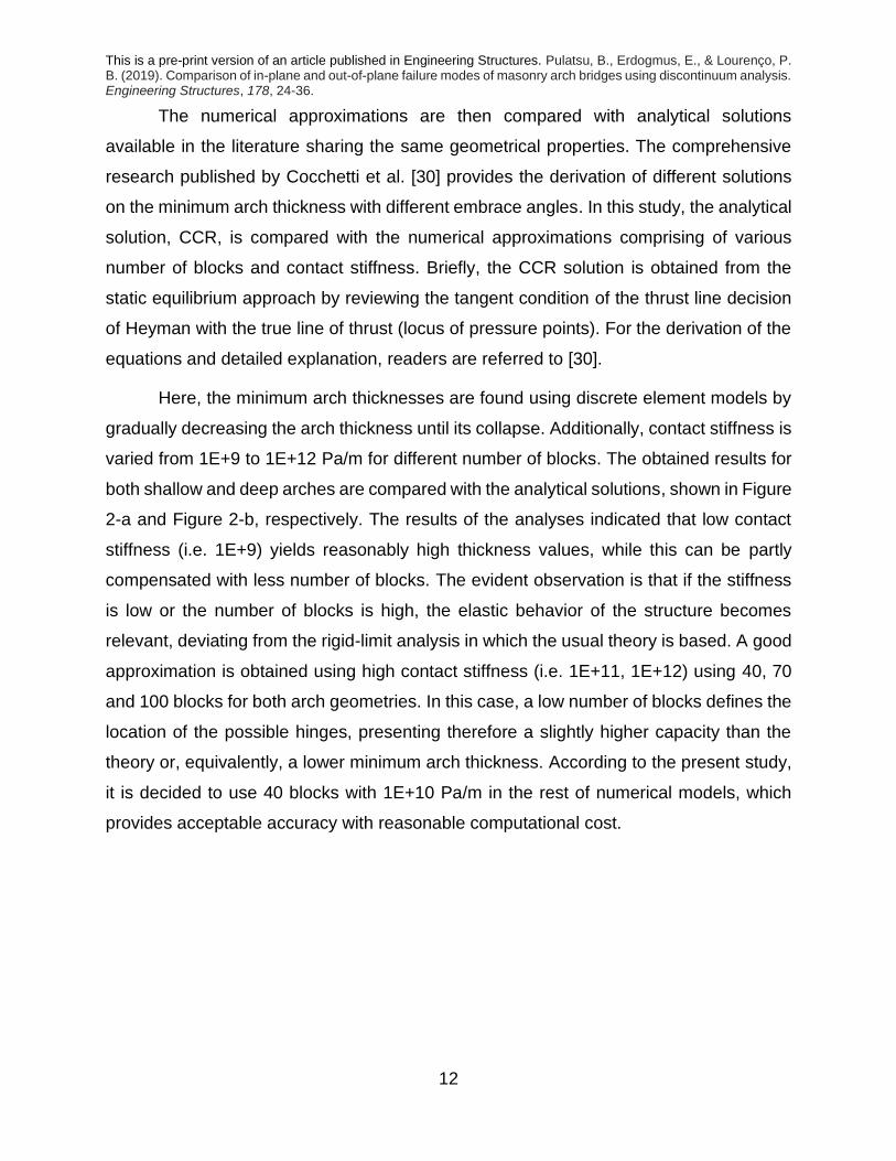
Here, the minimum arch thicknesses are found using discrete element models by
gradually decreasing the arch thickness until its collapse. Additionally, contact stiffness is
varied from 1E+9 to 1E+12 Pa/m for different number of blocks. The obtained results for
both shallow and deep arches are compared with the analytical solutions, shown in Figure
2-a and Figure 2-b, respectively. The results of the analyses indicated that low contact
stiffness (i.e. 1E+9) yields reasonably high thickness values, while this can be partly
compensated with less number of blocks. The evident observation is that if the stiffness
is low or the number of blocks is high, the elastic behavior of the structure becomes
relevant, deviating from the rigid-limit analysis in which the usual theory is based. A good
approximation is obtained using high contact stiffness (i.e. 1E+11, 1E+12) using 40, 70
and 100 blocks for both arch geometries. In this case, a low number of blocks defines the
location of the possible hinges, presenting therefore a slightly higher capacity than the
theory or, equivalently, a lower minimum arch thickness. According to the present study,
it is decided to use 40 blocks with 1E+10 Pa/m in the rest of numerical models, which
provides acceptable accuracy with reasonable computational cost.

This is a pre-print version of an article published in Engineering Structures. Pulatsu, B., Erdogmus, E., & Lourenço, P. B. (2019). Comparison of in-plane and out-of-plane failure modes of masonry arch bridges using discontinuum analysis. Engineering Structures, 178, 24-36.
13
a) Minimum arch thicknesses for deep
arch with different number of blocks and
contact stiffnesses.
b) Minimum arch thicknesses for shallow
arch with different number of blocks and
contact stiffnesses.
Figure 2. Parametric study on number of blocks and contact stiffness compared with
analytical solutions.
It is important to note that the minimum thickness of the shallow arch is derived
theoretically without any concern on practical applications. Additionally, the high contact
stiffnesses is used only to verify the convergence of results against the theoretical
solutions. In practice, the contact parameters should also correspond to the overall
deformability of the structure. In that context, the influence of the relationship between the
number of blocks and contact stiffnesses on the approximate equivalent Young’s Modulus
of the structure is shown in Table 3-1. The approximate equivalent elastic stiffness (𝐸𝑒𝑞)
of the discrete element model may be calculated as
𝐸𝑒𝑞 = 𝑘𝑁 · 𝑙𝐵𝑙𝑜𝑐𝑘 (20)
where 𝑙𝐵𝑙𝑜𝑐𝑘 represent the length of rigid block (voussoir). It is worth noting that
high number of blocks increase the deformability of the structure which effects the
stiffness of the model.

This is a pre-print version of an article published in Engineering Structures. Pulatsu, B., Erdogmus, E., & Lourenço, P. B. (2019). Comparison of in-plane and out-of-plane failure modes of masonry arch bridges using discontinuum analysis. Engineering Structures, 178, 24-36.
14
Table 3-1. Approximate equivalent Young’ Modulus, 𝐸𝑒𝑞 (Pa)
𝒌𝑵\𝐍𝐮𝐦𝐛𝐞𝐫 𝐨𝐟 𝐁𝐥𝐨𝐜𝐤𝐬 10 40 70 100
1E+9 6.26E+8 1.57E+8 8.98E+7 6.28E+7
1E+10 6.26E+9 1.57E+9 8.98E+8 6.28E+8
1E+11 6.26E+10 1.57E+10 8.98E+9 6.28E+9
3.2 Representative Masonry Arch Bridge Modeled
The masonry arch bridge database published by Oliveira et al. [31] is taken as a
reference for the geometrical properties of the masonry arch bridge models. The
suggested reference bridge geometries, which are the representative of 59 roadway
masonry arch bridges existing in the northwest Iberian Peninsula, are utilized to prepare
advanced and simplified numerical models. The geometrical properties and numerical
models of the reference masonry arch bridges, namely semi-shallow short span (SSS),
semi-shallow medium span (SMS), deep arch short span (DSS) and deep arch medium
span (DMS) are given in Table 3-2 and Figure 3, respectively.
Table 3-2. Geometrical properties of the representative masonry arch bridges
(dimensions are in meters).
Rise Thickness Span
Short Span arch
bridges
Semi-shallow
(SSS) 1.5 0.5 5
Deep arch (DSS) 2.5 0.6 5
Medium Span
arch bridges
Semi-shallow
(SMS) 3.0 0.7 10
Deep arch (DMS) 5.0 1.0 10
Granite is the main construction material (79% of the surveyed bridges) used in the
construction of these bridges among other materials, i.e. limestone, sandstone and schist.

This is a pre-print version of an article published in Engineering Structures. Pulatsu, B., Erdogmus, E., & Lourenço, P. B. (2019). Comparison of in-plane and out-of-plane failure modes of masonry arch bridges using discontinuum analysis. Engineering Structures, 178, 24-36.
15
The infill depth above the crown is taken as 0.4 meters. The spandrel wall thickness is
assumed as 0.5 for all reference models, which may vary between 0.4 – 1.2 meters
according to [32], and wall morphology is drawn randomly with an average masonry unit
length of 0.5 meters for medium span arches and 0.35 meters for short span, see [33] for
some typical stone dimensions in Portugal. All bridges are categorized as Class II,
meaning light and little intense traffic (agricultural pathways and passages and certain
municipal and forest roads) according to the Road Bridge Classification (RSA) in Portugal.
a) Deep Arch Short Span Bridge Model
(DSS)
b) Semi-shallow Arch Short Span Bridge
Model (SSS)
c) Deep Arch Medium Span Bridge Model
(DMS)
d) Semi-shallow Arch Medium Span
Bridge Model (SMS)
Figure 3. Representative masonry arch bridge models.

This is a pre-print version of an article published in Engineering Structures. Pulatsu, B., Erdogmus, E., & Lourenço, P. B. (2019). Comparison of in-plane and out-of-plane failure modes of masonry arch bridges using discontinuum analysis. Engineering Structures, 178, 24-36.
16
3.3 Comparison with Limit Analysis
In this part, only free-standing arch barrels are analyzed using two different
numerical techniques. First, computational limit analysis, initially proposed by Livesley
[34], is applied. A commonly used limit state analysis (LSA) software RING, [35], is utilized
to find capacity and corresponding collapse mechanisms of masonry arches. Then, the
same arch models are simulated via discrete element method, using the three-
dimensional discrete element code, 3DEC developed by ITASCA.
It is worth to note that LSA fills the gap between empirical rules and advanced
numerical solutions by providing a rapid analysis option. Furthermore, it requires much
lower need of input parameters when compared with any other sophisticated solutions,
i.e. nonlinear incremental analysis. Similar to DEM, masonry blocks are modeled explicitly
in limit analysis considering rigid perfectly plastic material model. Thus, in both numerical
approaches, masonry units are taken as rigid blocks and arch is loaded at the quarter
span (across the full width) without using backfill. There is no tensile and cohesion
strength are assigned at the joints. The friction angle between blocks is taken as 40
degrees to prevent any sliding failure. The obtained ultimate loads and corresponding
hinging mechanisms are given in Table 3-3 and Figure 4, respectively for the arches
introduced above. As expected, the two modeling techniques provided quantitative results
within 2% of each other and they displayed identical kinematic mechanisms.
Table 3-3. Ultimate load carrying capacity of semi-shallow and deep arches
3DEC Limit Analysis Difference (%)
SMS 592 kN 603 kN < 2
DMS 563 kN 568 kN < 1

This is a pre-print version of an article published in Engineering Structures. Pulatsu, B., Erdogmus, E., & Lourenço, P. B. (2019). Comparison of in-plane and out-of-plane failure modes of masonry arch bridges using discontinuum analysis. Engineering Structures, 178, 24-36.
17
a) Failure mechanism of Deep Arch
(DEM)
b) Failure mechanism of Deep Arch (LSA)
c) Failure mechanism of SMS (DEM) d) Failure mechanism of SMS (LSA)
Figure 4. Failure mechanism of discrete element masonry arch models loaded at the
quarter span.
4 Simulation of Masonry Arch Bridge Models
Masonry arch bridges have different kind of fill materials (designated as backfill and
usually soil), which play an important role on the strength of the bridges both by applying
passive pressure and providing live load dispersion on the arch barrel [36]. Therefore, an
investigation about the fill properties is necessary and beneficial to assess the capacity
of masonry arch bridges. In this part, 2D simplified approach and detailed numerical
models are compared. Then, the soil properties, friction angle and cohesion, are varied
in both methods and compared. The influence of pavement on the road is out of the scope
of this paper. Furthermore, two different live load patterns (Figure 5) are applied on the
bridges and corresponding collapse mechanisms are discussed. First, a vehicle load is
considered for a standard Portuguese vehicle composed of three axles spaced equally
1.5 meters apart, with a load of 100 kN per axle and a width of 2 meters [37]. Additionally,
uniform line load (i.e. knife edge) is applied along the total width between spandrel walls

This is a pre-print version of an article published in Engineering Structures. Pulatsu, B., Erdogmus, E., & Lourenço, P. B. (2019). Comparison of in-plane and out-of-plane failure modes of masonry arch bridges using discontinuum analysis. Engineering Structures, 178, 24-36.
18
as a second loading scenario. Both live load types (axles and knife edge), are applied at
the critical position on the backfill which is found using a simplified in-plane analysis.
a) Axle loads applied on rigid plates (half model with a longitudinal symmetry axis)
a) Knife-edge load applied through a rigid thin plate (half model with a longitudinal
symmetry axis)
Figure 5. DMS under different loading patterns.
In limit state analysis, a Boussinesq type dispersion of live load with an angle of 30
degrees is considered. Moreover, passive earth pressure is modeled using one

This is a pre-print version of an article published in Engineering Structures. Pulatsu, B., Erdogmus, E., & Lourenço, P. B. (2019). Comparison of in-plane and out-of-plane failure modes of masonry arch bridges using discontinuum analysis. Engineering Structures, 178, 24-36.
19
dimensional bar elements, or ‘backfill elements’, at the section of the arch barrel which
sways into the fill material [35]. The classical lateral earth pressure, developed for
retaining walls, is utilized based on Rankine theory. The relevant horizontal and vertical
soil pressures, acting on the extrados of a voussoir, are calculated explicitly. Active and
passive forces are automatically found by the RING software. On the other hand, in the
detailed 3D model, a mixed discrete-continuum approach is utilized in which the fill
material is modeled as a continuous finite element mesh by adopting the Mohr-Coulomb
failure criterion with ideal plastic behavior. The same modeling strategy was applied to
simulate the behavior and capacity of small-scale dry-joint retaining wall by Quezada et
al. [38]. Here, this strategy is further extended to masonry arch bridges. Throughout this
research, load-controlled analysis is performed. Local and global failure modes are
observed by monitoring the in-plane deflection of the arch voussoir and out of plane
deflection of the spandrel wall where the highest displacements are expected. Symmetry
boundary conditions are employed through the centerline of the bridge and only the half
of the bridge is modeled for computational efficiency. The translational degrees of
freedom of the nodes located at both ends of the backfill material are restricted through
the longitudinal direction and left free in vertical and transverse directions.
4.1 2D and 3D Modeling of Masonry Arch Bridges
First, the semi-shallow arch bridge with short span is subjected to a line load, applied
at the quarter span, using detailed and rigid block limit state models. Again, in both
computational techniques, masonry units are assumed as rigid blocks, thus, all
deformations are lumped at the joints. It is worth noting that severe deterioration of
materials, excessive live loads and fatigue problem may yield cracks and failure in the
masonry units that may affect the overall capacity of the structure. However, this research
focuses on the structural defects of the soil backfilled masonry arch bridges suffering from
weak mortar joints. Hence, there is no failure considered at the masonry units. The
reference masonry and soil backfill parameters along with the contact properties are given
in Table 4-1. It is worth noting that in limit state analysis the dead load of the spandrel
walls is included with the backfill and an averaged self-weight value of 21.25 kN/m3 is

This is a pre-print version of an article published in Engineering Structures. Pulatsu, B., Erdogmus, E., & Lourenço, P. B. (2019). Comparison of in-plane and out-of-plane failure modes of masonry arch bridges using discontinuum analysis. Engineering Structures, 178, 24-36.
20
used. The tensile strength and cohesion values are considered as zero with a friction
angle of 30 degrees at the joints between masonry units. This represents lower bound for
friction. The mechanical properties of the joints at the interfaces between masonry and
soil are also presented in Table 4-1.
Table 4-1. Reference material and contact properties (M-M: contact parameters
between masonry and masonry, M-S: contact parameters between masonry and soil)
Material
Properties
Backfill Self-weight (kN/m3) 20
Masonry Self-weight (kN/m3) 25
Backfill Elastic Modulus (MPa) 500
Poisson's Ratio 0.3
Backfill Cohesion (kPa) 20
Backfill Friction Angle
(degrees) 30
Backfill Tensile Strength (kPa) 0
Contact
Properties
kn, M-M (GPa/m) 10
ks, M-M (GPa/m) 4
kn, M-S (GPa/m) 1
ks, M-S (GPa/m) 0.4
Cohesion M-S (kPa) 0
Friction Angle M-S (degrees) 20
Tensile Strength M-S 0
Dilation angle 0
The results indicated that the detailed discontinuum analysis provided similar
results when compared with the simplified two-dimensional approach. Identical hinging
mechanisms are observed at the arch barrel, as shown in Figure 6. It is important to note
that although out of plane movements at the spandrel wall are recorded in the 3D model
during the analysis, the bridge collapsed due to in plane kinematic mechanism of the arch.

This is a pre-print version of an article published in Engineering Structures. Pulatsu, B., Erdogmus, E., & Lourenço, P. B. (2019). Comparison of in-plane and out-of-plane failure modes of masonry arch bridges using discontinuum analysis. Engineering Structures, 178, 24-36.
21
a) Collapse Mechanism (2D) Limit State Analysis (RING)
b) DEM Model (3DEC)
Figure 6. Collapse mechanism of semi shallow masonry arch bridge with short span
model.
Additionally, the difference in capacity is lower than 5 % as shown in Figure 7.
However, this may not be the case for all situations, since type of loading, backfill
properties and geometrical characteristics of the structure may affect the collapse
mechanism, hence, the load carrying capacity.

This is a pre-print version of an article published in Engineering Structures. Pulatsu, B., Erdogmus, E., & Lourenço, P. B. (2019). Comparison of in-plane and out-of-plane failure modes of masonry arch bridges using discontinuum analysis. Engineering Structures, 178, 24-36.
22
Figure 7. Comparison the results of Limit State Analysis and Discrete Element Model.
4.2 Parametric Study on Backfill Properties
Parametric study is performed on the mechanical properties of the backfill by varying the
friction angle and cohesion in both computational methods, using the same example as
before. According to the analysis, for higher cohesion values, the detailed discrete
element model provided higher load carrying capacities than limit state analysis. This may
be expected from the simplified approach since the backfill interaction is taken into
account only approximately. On the other hand, in terms of friction angle variation, both
approaches give results reasonably close to each other compared to variation in
cohesion. In Figure 8, it is possible to observe the pronounced effect of the backfill on the
load carrying capacity of the masonry arch bridges. The simplified approach provided
conservative results, especially for the cohesive infill material. Hence, elasto-plastic
formulation for the backfill material give higher load bearing capacities compared to the
simplified solution, which is less sensitive to backfill properties. The obtained results are
in line with the comparison between other advanced modeling strategies and simplified
solutions, presented by [39,40].

This is a pre-print version of an article published in Engineering Structures. Pulatsu, B., Erdogmus, E., & Lourenço, P. B. (2019). Comparison of in-plane and out-of-plane failure modes of masonry arch bridges using discontinuum analysis. Engineering Structures, 178, 24-36.
23
.
a) Influence of friction angle on the limit
and discrete element models.
b) Influence of cohesion on the limit and
discrete element models.
Figure 8. Influence of backfill properties (friction and cohesion) on the 2D limit state
analysis and 3D discrete element models, for semi-shallow arch bridge with short span.
4.3 Parametric Study on the Coulomb Joint Parameters between Masonry
and Soil
The presented advanced numerical modeling strategy has a clear advantage in
terms of modeling of the cracks and large displacement with respect to other numerical
methods. However, contact constitutive laws, assigned by the modeler, should be
selected carefully since, they have a physical meaning and influence on the structure.
The common contact law for discrete element modeling of masonry structures is the
Coulomb joint model with tension cut-off. However, there is not much knowledge on the
effect of contact parameters for the interaction between backfill material and masonry.
Here, cohesion strength and friction angle are varied and load carrying capacity of the
bridges are recorded.
It is observed that the friction angle has a pronounced influence on the overall
capacity of masonry arch bridge, although, this did not change the failure mechanism due

This is a pre-print version of an article published in Engineering Structures. Pulatsu, B., Erdogmus, E., & Lourenço, P. B. (2019). Comparison of in-plane and out-of-plane failure modes of masonry arch bridges using discontinuum analysis. Engineering Structures, 178, 24-36.
24
to stiff form of the arch barrel (Table 4-2). On the other hand, cohesion strength
demonstrated less influence, even no influence for shallow arch bridges, on the load
carrying capacity compared to the friction angle.
Table 4-2 Contribution of the contact parameter, friction angle, between masonry and
soil on the capacity of the masonry arch bridge (Cohesion is taken as zero).
Bridge Contact Friction Angle between M-S Load Carrying Capacity (kN)
SSS
20 840
30 960
40 1000
SMS
20 960
30 1175
40 1248
DSS
20 865
30 960
40 1020
DMS
20 1440
30 1920
40 2016
5 Discussion on Spandrel Wall Behavior
The spandrel wall failures may be critical for the use of masonry arch bridges and
for life safety. The spandrel wall failures may be observed in different forms depending
on the interaction between masonry and soil backfill as well as the geometrical properties
of the structure. The out-of-plumbness, sliding and bulging movements of the spandrel
walls over the extrados of the arch barrel are the several structural defects observed
during the survey, as shown in Figure 9. Furthermore, the excessive vegetation due to
absence of mortar in the stone joints and longitudinal cracks in the arch barrel are the
other most common problems [40,41,42].

This is a pre-print version of an article published in Engineering Structures. Pulatsu, B., Erdogmus, E., & Lourenço, P. B. (2019). Comparison of in-plane and out-of-plane failure modes of masonry arch bridges using discontinuum analysis. Engineering Structures, 178, 24-36.
25
a) Sliding of the spandrel wall over the
arch barrel.
b) Out-of-plane deflection of the spandrel
wall.
Figure 9. Spandrel wall deflections (Pont Donim, Portugal)
Spandrel wall analysis requires 3D models and complex numerical predictions that
has been mostly done by macro-modeling approach, where the mechanical properties of
masonry are smeared as a homogenous medium, to take the advantage of lower
computational cost. Simplified processes have also been proposed to account for
transverse actions in masonry arch bridges [42].
In this study, a more detailed approach is presented by considering a discontinuous
displacement field in all masonry components of the arch bridge to provide realistic
collapse mechanisms and more accurate load carrying capacity estimations. Both loading
scenarios that are discussed previously are applied and the results show a remarkable
out of plane displacement at the spandrel wall, which can yield up to 65% reduction on
the load carrying capacity under the vehicle type of loading. The monitoring locations, on
the spandrel wall and arch barrel, where the in-plane and out-of-plane displacements are
recorded respectively, are shown for deep arch with medium span model in Figure 10.

This is a pre-print version of an article published in Engineering Structures. Pulatsu, B., Erdogmus, E., & Lourenço, P. B. (2019). Comparison of in-plane and out-of-plane failure modes of masonry arch bridges using discontinuum analysis. Engineering Structures, 178, 24-36.
26
Obtained spandrel wall failures for deep and semi-shallow medium span arches are
shown in Figure 11 and Figure 12, respectively. It is particularly noteworthy that the
collapse mechanism of spandrel wall includes the combination of sliding of spandrel walls
on the arch barrel and inevitable overturning failure. The damage progression in the
numerical model started with the lateral sliding of the spandrel wall from the arch ring.
Then, visible cracks appeared on the spandrel wall, which ended up with an overturning
mechanism. The observed failure mechanism in the numerical model is aligned with a
similar experimental test, presented by Boothby et al. [43]. Additionally, longitudinal
cracks were observed at the intrados of the arch barrel due to soil pressure, close to the
region where live loads were applied (Figure 13). Similar collapse mechanisms were
observed for the other three representative masonry arch bridges as well. The presented
numerical simulations highlight the importance of 3D behavior and necessity of detailed
modeling to understand the structural behavior of the masonry arch bridges.
Figure 10. Monitoring points on arch barrel (R1) and spandrel wall (R2).

This is a pre-print version of an article published in Engineering Structures. Pulatsu, B., Erdogmus, E., & Lourenço, P. B. (2019). Comparison of in-plane and out-of-plane failure modes of masonry arch bridges using discontinuum analysis. Engineering Structures, 178, 24-36.
27
Figure 11. Spandrel wall failure of DMS (Colors display displacement magnitude)
Figure 12. Spandrel wall failure of DSS (Colors display displacement magnitude).

This is a pre-print version of an article published in Engineering Structures. Pulatsu, B., Erdogmus, E., & Lourenço, P. B. (2019). Comparison of in-plane and out-of-plane failure modes of masonry arch bridges using discontinuum analysis. Engineering Structures, 178, 24-36.
28
Figure 13. Out of plane displacement and the longitudinal cracks at the intrados of the arch barrel (Colors display displacement magnitude).
There is no significant effect of the contact parameters between masonry components of
the examined arch bridges observed on the out-of-plane failure mode. However, in
prepared case studies the spandrel wall height and the soil backfill depth is relatively low
(0.4 m at the crown), which makes more likely to obtain sliding phenomena, rather than
pure overturning. The capacity curves are given for all of the representative masonry
bridges in Figure 14 under vehicle and knife edge loading. Results of the analysis
indicates that the vehicle types of loading lead to a more critical force distribution on the
spandrel wall than the knife edge loading and is more likely to cause a spandrel wall
failure. It was noticed that loading plates, replicating the tire pressures, have a higher
tendency to create transversal deflections of soil backfill (sliding) once the applied shear
stress is higher than the shear strength of the backfill material. The arch barrel did not
involve in the failure mechanism when bridges were subjected to vehicle loading. The
out-of-plane deflection and the corresponding displacement field may be seen in Figure
15. Furthermore, the recorded spandrel wall deformations in the transversal direction are
given in Figure 16.

This is a pre-print version of an article published in Engineering Structures. Pulatsu, B., Erdogmus, E., & Lourenço, P. B. (2019). Comparison of in-plane and out-of-plane failure modes of masonry arch bridges using discontinuum analysis. Engineering Structures, 178, 24-36.
29
On the other hand, knife edge loading yielded plastic hinging mechanism on the arch
barrel and tensile cracks on the spandrel wall. Furthermore, there were limited spandrel
wall deflections in the out-of-plane direction measured and the governing failure mode
was a hinging mechanism of the arch barrel as shown in Figure 17. Therefore, the
application of different type of pressures on the soil backfill will make critical response
changes in masonry arch bridges. The results exhibit the lower and upper bounds for a
masonry arch bridge, in which latter represents the collapse of arch barrel and former
indicates the spandrel wall failure.
a) Force vs Displacement curves of Deep
Arch with Medium Span Bridge (Deflection
Recorded at the Arch Barrel, R1)
b) Force vs Displacement curves of Deep
Arch with Sort Span Bridge (Deflection
Recorded at the Arch Barrel, R1)

This is a pre-print version of an article published in Engineering Structures. Pulatsu, B., Erdogmus, E., & Lourenço, P. B. (2019). Comparison of in-plane and out-of-plane failure modes of masonry arch bridges using discontinuum analysis. Engineering Structures, 178, 24-36.
30
c) Force vs Displacement curves of Semi-
Shallow Arch with Medium Span Bridge
(Deflection Recorded at the Arch Barrel,
R1)
d) Force vs Displacement curves of Semi-
Shallow Arch with Short Span Bridge
(Deflection Recorded at the Arch Barrel,
R1)
Figure 14. Capacity curves of four representative bridge model under two types of
loading.

This is a pre-print version of an article published in Engineering Structures. Pulatsu, B., Erdogmus, E., & Lourenço, P. B. (2019). Comparison of in-plane and out-of-plane failure modes of masonry arch bridges using discontinuum analysis. Engineering Structures, 178, 24-36.
31
Figure 15. Deflection of spandrel wall (Plan view) and the out of plane displacement field at each cross section of loading plates under vehicle loading.

This is a pre-print version of an article published in Engineering Structures. Pulatsu, B., Erdogmus, E., & Lourenço, P. B. (2019). Comparison of in-plane and out-of-plane failure modes of masonry arch bridges using discontinuum analysis. Engineering Structures, 178, 24-36.
32
a) Deep Arch with Medium and Short Span
Bridges under Vehicle Loading (Deflection
Recorded at the Spandrel Wall, R2)
b) Semi-Shallow Arch with Medium and
Short Span Bridges under Vehicle Loading
(Deflection Recorded at the Spandrel
Wall, R2)
Figure 16. Out of plane displacement of medium and short span masonry arch bridge
spandrel walls under vehicle loading.
Figure 17. In-plane collapse mechanism of DMS under knife-edge loading (Colors display displacement magnitude).

This is a pre-print version of an article published in Engineering Structures. Pulatsu, B., Erdogmus, E., & Lourenço, P. B. (2019). Comparison of in-plane and out-of-plane failure modes of masonry arch bridges using discontinuum analysis. Engineering Structures, 178, 24-36.
33
6 Conclusions
This research provides a better understanding of the complex behavior of masonry
arch bridges by considering the influence of the backfill properties, contact between
backfill and masonry, type of vehicle load assumed and spandrel wall vulnerability. First,
the discontinuous and nonlinear characteristics of masonry bridges are simulated via a
mixed discrete-continuum modeling strategy by conducting parametric analysis with a
simplified approach, namely computational limit state analysis. A good agreement is
found between the limit state analysis and the detailed numerical model for a shallow arch
bridge with short span. In-plane collapse mode is obtained where masonry arch barrel
failed due to plastic hinging mechanism. However, it is concluded that to understand the
full structural response of masonry arch bridges, three-dimensional models are needed,
which has the capability of simulating the transversal deflections, of the spandrel walls.
From the advanced simulations, the following conclusions were derived:
(a) The cohesion of the backfill has a considerable influence on the capacity of
masonry arch bridges, while friction of the backfill seems to have a lesser effect in
comparison;
(b) The frictional resistance plays a key role at the interface between masonry and
infill material, while the cohesion plays a less relevant role;
(c) The type of loading has a drastic impact on the capacity of masonry arch bridges.
Under vehicle (point) loading, failure mode is governed by the spandrel wall failure. It is
therefore noted that multiple concentrated loads provide different effect than a line load.
In addition, this research indicated the potential of mix discrete-continuum approach
through the application on masonry arch bridges. In future studies, various structural
problems of masonry arch bridges such as scour, and support settlement will be explored
via this numerical modeling strategy.

This is a pre-print version of an article published in Engineering Structures. Pulatsu, B., Erdogmus, E., & Lourenço, P. B. (2019). Comparison of in-plane and out-of-plane failure modes of masonry arch bridges using discontinuum analysis. Engineering Structures, 178, 24-36.
34
Acknowledgments
Authors would like to express their gratitude to Itasca Educational Partnership Program (IEP) for
their kind support and providing 3DEC software. Furthermore, authors would like to acknowledge
the valuable help of Dr. Jim Hazzard, Itasca Consulting Group, for his technical support.
7 References
[1] Fanning PJ, Boothby TE, Roberts BJ. Longitudinal and transverse effects in masonry arch assessment. Constr Build Mater 2001;15:51–60. doi:10.1016/S0950-0618(00)00069-6.
[2] Tomor AK, McAulay S. Overview of design guidelines for masonry arch bridges. Struct Anal Hist Constr Anamn Diagnosis, Ther Control - Proc 10th Int Conf Struct Anal Hist Constr SAHC 2016 2016:598–603.
[3] Citto C, Woodham DB. Evaluating Existing and Historic Stone Arch Bridges. STRUCTURE 2015:14–8.
[4] Orbán Z. UIC Project on assessment , inspection and maintenance of masonry arch railway bridges. 5th Int Conf Arch Bridg 2007:3–12.
[5] Zucchini A, Lourenço PB. A micro-mechanical homogenisation model for masonry: Application to shear walls. Int J Solids Struct 2009;46:871–86. doi:10.1016/j.ijsolstr.2008.09.034.
[6] Boothby TE. Analysis of masonry arches and vaults. Prog Struct Eng Mater 2001;3:246–56. doi:10.1002/pse.84.
[7] Brencich A, De Francesco U. Assessment of Multispan Masonry Arch Bridges. I: Simplified Approach. J Bridg Eng 2004;9:582–90. doi:10.1061/(ASCE)1084-0702(2004)9:6(582).
[8] Brencich A, De Francesco U. Assessment of Multispan Masonry Arch Bridges II: Examples and Applications. J Bridg Eng 2004;9:591–8. doi:10.1061/(ASCE)1084-0702(2004)9:6(591).
[9] De Santis S, de Felice G. A fibre beam-based approach for the evaluation of the seismic capacity of masonry arches. Earthq Eng Struct Dyn 2014;43:1661–81. doi:10.1002/eqe.2416.
[10] Conde B, Drosopoulos GA, Stavroulakis GE, Riveiro B, Stavroulaki ME. Inverse analysis of masonry arch bridges for damaged condition investigation: Application on Kakodiki bridge. Eng Struct 2016;127:388–401. doi:10.1016/j.engstruct.2016.08.060.
[11] Betti M, Drosopoulos GA, Stavroulakis GE. Two non-linear finite element models developed for the assessment of failure of masonry arches. Comptes Rendus - Mec 2008;336:42–53. doi:10.1016/j.crme.2007.10.014.

This is a pre-print version of an article published in Engineering Structures. Pulatsu, B., Erdogmus, E., & Lourenço, P. B. (2019). Comparison of in-plane and out-of-plane failure modes of masonry arch bridges using discontinuum analysis. Engineering Structures, 178, 24-36.
35
[12] Zhang Y, Macorini M, Izzudin BA. Mesoscale Partitioned Analysis of Brick-Masonry Arches. Eng Struct 2016;to appear:142–66. doi:10.1016/j.engstruct.2016.05.046.
[13] Fanning PJ, Boothby TE. Three-dimensional modelling and full-scale testing of stone arch bridges. Comput Struct 2001;79:2645–62. doi:10.1016/S0045-7949(01)00109-2.
[14] Conde B, Ramos LF, Oliveira D V., Riveiro B, Solla M. Structural assessment of masonry arch bridges by combination of non-destructive testing techniques and three-dimensional numerical modelling: Application to Vilanova bridge. Eng Struct 2017;148:621–38. doi:10.1016/j.engstruct.2017.07.011.
[15] Senthivel R, Lourenço PB. Finite element modelling of deformation characteristics of historical stone masonry shear walls. Eng Struct 2009;31:1930–43. doi:10.1016/j.engstruct.2009.02.046.
[16] Lourenço PB, Rots JG. Multisurface interface model for analysis of masonry structures. J Eng Mech 1997;123:660–8.
[17] Lemos J V. Discrete Element Modeling of Masonry Structures. Int J Archit Herit 2007;1:190–213. doi:10.1080/15583050601176868.
[18] Lemos J. Assessment of the ultimate load of a masonry arch using discrete elements. Comput Methods Struct Mason 1995:294–302.
[19] Thavalingam A, Bicanic N, Robinson JI, Ponniah DA. Computational framework for discontinuous modelling of masonry arch bridges. Comput Struct 2001;79:1821–30. doi:10.1016/S0045-7949(01)00102-X.
[20] Bićanić N, Stirling C, Pearce CJ. Discontinuous modelling of masonry bridges. Comput Mech 2003;31:60–8. doi:10.1007/s00466-002-0393-0.
[21] Tóth AR, Orbán Z, Bagi K. Discrete element analysis of a stone masonry arch. Mech Res Commun 2009;36:469–80. doi:10.1016/j.mechrescom.2009.01.001.
[22] Sarhosis V, Oliveira DV, Lemos JV, Lourenco PB. The effect of skew angle on the mechanical behaviour of masonry arches. Mech Res Commun 2014;61:53–9. doi:10.1016/j.mechrescom.2014.07.008.
[23] Pulatsu B, Erdogmus E, Bretas EM. Parametric Study on Masonry Arches Using 2D Discrete Element Modeling. J Archit Eng 2018;24. doi:10.1061/(ASCE)AE.1943-5568.0000305.
[24] Roca P, Molins C. Experiments on arch bridges. In: Roca P, Molins C, editors. Arch Bridg. IV-Advances Assessment, Struct. Des. Constr., Barcelona: 2004, p. 365–74.
[25] Cundall PA, Hart RD. Numerical modelling of discontinua. Eng Comput 1992;9:101–13. doi:10.1108/eb023851.
[26] Cundall PA. Formulation of a three-dimensional distinct element model—Part I. A scheme to detect and represent contacts in a system composed of many polyhedral blocks. Int J Rock Mech Min Sci Geomech Abstr 1988;25:107–16.
[27] ITASCA. 3DEC Universial Discrete Element Code Theory and Background. Minneapolis: 2004.

This is a pre-print version of an article published in Engineering Structures. Pulatsu, B., Erdogmus, E., & Lourenço, P. B. (2019). Comparison of in-plane and out-of-plane failure modes of masonry arch bridges using discontinuum analysis. Engineering Structures, 178, 24-36.
36
[28] Simon J, Bagi K. Discrete element analysis of the minimum thickness of oval masonry domes. Int J Archit Herit 2014;3058. doi:10.1080/15583058.2014.996921.
[29] Pulatsu B, Bretas EM, Lourenco PB. Discrete element modeling of masonry structures: Validation and application. Earthquakes Struct 2016;11:563–82. doi:10.12989/eas.2016.11.4.563.
[30] Cocchetti G, Colasante G, Rizzi E. On the Analysis of Minimum Thickness in Circular Masonry Arches. Appl Mech Rev 2011;64:051002. doi:10.1115/1.4007417.
[31] Oliveira D V., Lourenço PB, Lemos C. Geometric issues and ultimate load capacity of masonry arch bridges from the northwest Iberian Peninsula. Eng Struct 2010;32:3955–65. doi:10.1016/j.engstruct.2010.09.006.
[32] Rota M, Pecker A, Bolognini D, Pinho R. A Methodology for Seismic Vulnerability of Masonry Arch Bridge Walls. J Earthq Eng 2005;9:331–53. doi:doi.org/10.1142/S1363246905002432.
[33] Riveiro B, Lourenço PB, Oliveira D V., González-Jorge H, Arias P. Automatic Morphologic Analysis of Quasi-Periodic Masonry Walls from LiDAR. Comput Civ Infrastruct Eng 2016;31:305–19. doi:10.1111/mice.12145.
[34] Livesley RK. Limit analysis of structures formed from rigid blocks. Int J Numer Methods Eng 1978;12:1853–71. doi:10.1002/nme.1620121207.
[35] LimitState. Ring manuel version 3.2.b. Sheffield: 2016.
[36] Callaway P, Gilbert M, Smith C. Influence of backfill on the capacity of masonry arch bridges. Proc ICE-Bridge Eng 2012;165:147–58. doi:10.1680/bren.11.00038.
[37] RSA. RSA Safety and Load Code for Buildings and Bridge Structures. Decreto Lei No. 235/83 [in Portuguese]. Lisboa, Portugal: 1983.
[38] Quezada JC, Vincens E, Mouterde R, Morel JC. 3D failure of a scale-down dry stone retaining wall: A DEM modelling. Eng Struct 2016;117:506–17. doi:10.1016/j.engstruct.2016.03.020.
[39] Milani G, Lourenço PB. 3D non-linear behavior of masonry arch bridges. Comput Struct 2012;110–111:133–50. doi:10.1016/j.compstruc.2012.07.008.
[40] Conde B, Díaz-Vilariño L, Lagüela S, Arias P. Structural analysis of Monforte de Lemos masonry arch bridge considering the influence of the geometry of the arches and fill material on the collapse load estimation. Constr Build Mater 2016;120:630–42. doi:10.1016/j.conbuildmat.2016.05.107.
[41] Oliveira D V, Louren. Repair of stone masonry arch bridges. Arch Bridg - ARCH’04 2004:1–8.
[42] Erdogmus E, Boothby T. Strength of Spandrel Walls in Masonry Arch Bridges. Transp Res Rec J Transp Res Board 2004;1892:47–55. doi:10.3141/1892-06.
[43] Boothby TE, Yurianto Y, Erdogmus E. Experimental Replication of Masonry Arch Bridge Spandrel Wall Collapse. Mason Soc J 2005;23.
View publication statsView publication stats