Comparison of CAMRAD II and RCAS Predictions of Tiltrotor ...
13
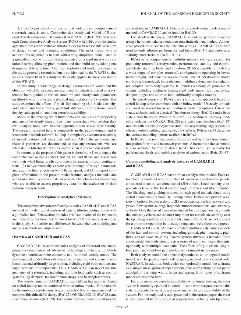
JOURNAL OF THE AMERICAN HELICOPTER SOCIETY 63, 022001 (2018) Comparison of CAMRAD II and RCAS Predictions of Tiltrotor Aeroelastic Stability Hyeonsoo Yeo ∗ Jeffrey Bosworth C. W. Acree, Jr. Andrew R. Kreshock U.S. Army Aviation Development Directorate Rotor Dynamics Aeromechanics Office U.S. Army Research Laboratory Aviation and Missile Research Bell Helicopter National Aeronautics and Vehicle Technology Directorate Development and Engineering Center Textron, Inc. Space Administration Hampton, VA Research, Development, and Engineering Command Fort Worth, TX Ames Research Center Ames Research Center, Moffett Field, CA Moffett Field, CA Tiltrotor whirl flutter in cruise flight is investigated using comprehensive rotorcraft analysis codes Comprehensive Analytical Model of Rotorcraft Aerodynamics and Dynamics (CAMRAD) II and Rotorcraft Comprehensive Analysis System (RCAS). A generic tiltrotor model with a three-bladed gimballed rotor was systematically developed starting with a simple rigid rotor mounted on a rigid pylon and a more sophisticated model was built up by adding one design variable at a time. The rotor is also coupled with a flexible wing/pylon modeled from NASTRAN for aeroelastic stability analysis. The effects of pitch–flap coupling (δ 3 ), blade elasticity, precone, undersling, yoke chord and flap stiffness, pitch link stiffness, rotor rotational speed, density, speed of sound, inflow modeling, unsteady aerodynamics, and realistic airfoil tables on whirl flutter speed are thoroughly examined. With careful and thorough modeling/analysis, aeroelastic stability (frequency and damping) calculated by CAMRAD II and RCAS shows consistently excellent agreement with each other for wide variations of design variables and operating conditions. For the configurations investigated in this study, blade pitch–flap coupling, rotor lag frequency, rotor rotational speed, and density have an important influence on whirl flutter speed. Nomenclature a speed of sound k x ,k y ,k z pitch bearing translational stiffness k θx ,k θy ,k θz pitch bearing rotational stiffness R blade radius V speed X, Y, Z translational NASTRAN mode shape at rotor hub β flap angle θ blade pitch angle δ 3 pitch–flap coupling θ X ,θ Y ,θ Z rotational NASTRAN mode shape at rotor hub ν ζ blade fundamental lag mode frequency ρ freestream density rotor rotational speed Introduction Aeroelastic instability, specifically whirl flutter, at high-speed air- plane mode is a major concern for successful design of future tiltrotor ∗ Corresponding author; email: [email protected]. Presented at the American Helicopter Society 73rd Annual Forum, Fort Worth, TX, May 9–11, 2017. Manuscript received May 2017; accepted November 2017. aircraft. A major risk mitigation step for aeroelastic instability in the design and development of tiltrotors is the use of modeling and simula- tion analyses to ensure adequate speed margins. The principal factor of whirl mode instability is inplane forces of the proprotors coupled with a flexible wing/pylon structure. Considerable experimental and analytical research has been conducted on tiltrotor whirl flutter (Refs. 1–16). To accurately model a sophisticated tiltrotor system, comprehensive rotor- craft analysis codes and multibody dynamics codes have been used to understand fundamental mechanisms and correlate with available test data (Refs. 17–22). The validation of analytical methods has met with only limited success. The current analytical tools are not always able to accurately capture changes in the whirl flutter boundary caused by para- metric variations. Moreover, significant differences are observed among the analytical tools used. This raises questions about the validity of the current state-of-the-art modeling and simulation tools for the prediction of tiltrotor whirl flutter. The failure of comprehensive rotorcraft analysis and multibody dy- namics codes to consistently match each other’s predictions for the WRATS (Wing and Rotor Aeroelastic Test System) model (Refs. 17–22) is a major incentive for the current effort. The WRATS is a 1/5-scale semispan aeroelastic model of the Joint Services Advanced Vertical Lift Aircraft (JVX), which evolved intothe V-22 tiltrotor. The WRATS was tested in the Langley Transonic Dynamics Tunnel (TDT). There have been a number of WRATS tests conducted at the TDT that explored different configurations (Refs. 13, 16, 23, 24). DOI: 10.4050/JAHS.63.022001 C 2018 AHS International 022001-1
Transcript of Comparison of CAMRAD II and RCAS Predictions of Tiltrotor ...
JOURNAL OF THE AMERICAN HELICOPTER SOCIETY 63, 022001 (2018)
Comparison of CAMRAD II and RCAS Predictions of TiltrotorAeroelastic Stability
Hyeonsoo Yeo∗ Jeffrey Bosworth C. W. Acree, Jr. Andrew R. KreshockU.S. Army Aviation Development Directorate Rotor Dynamics Aeromechanics Office U.S. Army Research Laboratory
Aviation and Missile Research Bell Helicopter National Aeronautics and Vehicle Technology DirectorateDevelopment and Engineering Center Textron, Inc. Space Administration Hampton, VA
Research, Development, and Engineering Command Fort Worth, TX Ames Research CenterAmes Research Center, Moffett Field, CA Moffett Field, CA
Tiltrotor whirl flutter in cruise flight is investigated using comprehensive rotorcraft analysis codes Comprehensive AnalyticalModel of Rotorcraft Aerodynamics and Dynamics (CAMRAD) II and Rotorcraft Comprehensive Analysis System (RCAS).A generic tiltrotor model with a three-bladed gimballed rotor was systematically developed starting with a simple rigidrotor mounted on a rigid pylon and a more sophisticated model was built up by adding one design variable at a time.The rotor is also coupled with a flexible wing/pylon modeled from NASTRAN for aeroelastic stability analysis. The effectsof pitch–flap coupling (δ3), blade elasticity, precone, undersling, yoke chord and flap stiffness, pitch link stiffness, rotorrotational speed, density, speed of sound, inflow modeling, unsteady aerodynamics, and realistic airfoil tables on whirlflutter speed are thoroughly examined. With careful and thorough modeling/analysis, aeroelastic stability (frequency anddamping) calculated by CAMRAD II and RCAS shows consistently excellent agreement with each other for wide variationsof design variables and operating conditions. For the configurations investigated in this study, blade pitch–flap coupling,rotor lag frequency, rotor rotational speed, and density have an important influence on whirl flutter speed.
Nomenclature
a speed of soundkx, ky, kz pitch bearing translational stiffnesskθx
, kθy, kθz
pitch bearing rotational stiffnessR blade radiusV speedX, Y, Z translational NASTRAN mode shape at rotor hubβ flap angle�θ blade pitch angleδ3 pitch–flap couplingθX, θY , θZ rotational NASTRAN mode shape at rotor hubνζ blade fundamental lag mode frequencyρ freestream density rotor rotational speed
Introduction
Aeroelastic instability, specifically whirl flutter, at high-speed air-plane mode is a major concern for successful design of future tiltrotor
∗Corresponding author; email: [email protected] at the American Helicopter Society 73rd Annual Forum, Fort Worth,TX, May 9–11, 2017. Manuscript received May 2017; accepted November 2017.
aircraft. A major risk mitigation step for aeroelastic instability in thedesign and development of tiltrotors is the use of modeling and simula-tion analyses to ensure adequate speed margins. The principal factor ofwhirl mode instability is inplane forces of the proprotors coupled with aflexible wing/pylon structure. Considerable experimental and analyticalresearch has been conducted on tiltrotor whirl flutter (Refs. 1–16). Toaccurately model a sophisticated tiltrotor system, comprehensive rotor-craft analysis codes and multibody dynamics codes have been used tounderstand fundamental mechanisms and correlate with available testdata (Refs. 17–22). The validation of analytical methods has met withonly limited success. The current analytical tools are not always able toaccurately capture changes in the whirl flutter boundary caused by para-metric variations. Moreover, significant differences are observed amongthe analytical tools used. This raises questions about the validity of thecurrent state-of-the-art modeling and simulation tools for the predictionof tiltrotor whirl flutter.
The failure of comprehensive rotorcraft analysis and multibody dy-namics codes to consistently match each other’s predictions for theWRATS (Wing and Rotor Aeroelastic Test System) model (Refs. 17–22)is a major incentive for the current effort. The WRATS is a 1/5-scalesemispan aeroelastic model of the Joint Services Advanced Vertical LiftAircraft (JVX), which evolved into the V-22 tiltrotor. The WRATS wastested in the Langley Transonic Dynamics Tunnel (TDT). There havebeen a number of WRATS tests conducted at the TDT that exploreddifferent configurations (Refs. 13, 16, 23, 24).
DOI: 10.4050/JAHS.63.022001 C© 2018 AHS International022001-1
H. YEO JOURNAL OF THE AMERICAN HELICOPTER SOCIETY
A study began recently to ensure that widely used comprehensiverotorcraft analysis tools, Comprehensive Analytical Model of Rotor-craft Aerodynamics and Dynamics (CAMRAD) II (Ref. 25) and Rotor-craft Comprehensive Analysis System (RCAS) (Ref. 26), provide similaragreement for a representative tiltrotor model with reasonable variationsof design values and operating conditions. The most logical way toachieve this objective is to start with a very simplified model, such asa gimballed rotor with rigid blades mounted on a rigid mast with a ro-tational spring allowing pitch motion, and then build up by adding onedesign variable at a time. The most sophisticated model developed inthis study generally resembles, but is not identical to, the WRATS so thatlessons learned from this study can be easily applied to analytical studiesof the WRATS.
In this study, a wide range of design parameters are varied and theeffects on whirl flutter speed are examined. Emphasis is placed on a sys-tematic investigation of various structural and aerodynamic parameterson tiltrotor whirl flutter and a physical interpretation of the results. Thisstudy examines the effects of pitch–flap coupling (δ3), blade elasticity,yoke chord and flap stiffness, pitch link stiffness, rotor rotational speed,density, and speed of sound on aeroelastic stability.
Much of the existing whirl flutter data and analyses are proprietaryand cannot be openly shared; thus many researchers who develop theirown analysis tools have limited opportunities to assess their validity.The research reported here is completely in the public domain and isstructured to include a careful buildup in complexity to ensure traceabilityof model features and analytical methods. All of the geometric andmaterial properties are documented so that any researchers who areinterested in tiltrotor whirl flutter analysis can reproduce our results.
In summary, the purpose of this paper is threefold: (1) to compare thecomprehensive analysis codes CAMRAD II and RCAS and assess howwell their whirl flutter predictions match for generic tiltrotor configura-tions, (2) to systematically explore a wide range of design parametersand examine their effects on whirl flutter speed, and (3) to report com-plete information on the present model features, analysis methods, andaeroelastic stability results that can provide a benchmark for researcherswho are unable to access proprietary data for the evaluation of theirin-house analysis tools.
Description of Analytical Methods
The comprehensive rotorcraft analysis codes CAMRAD II and RCASare used for modeling and analysis of generic tiltrotor configurations witha gimballed hub. This section provides brief summaries of the two codesand then describes how they are used for whirl flutter analysis in cruisein this study. Similarities and differences between the two modeling andanalysis methods are emphasized.
Overview of CAMRAD II and RCAS
CAMRAD II is an aeromechanics analysis of rotorcraft that incor-porates a combination of advanced technologies including multibodydynamics, nonlinear finite elements, and rotorcraft aerodynamics. Themathematical model allows structural, aerodynamic, and kinematic non-linearities and arbitrarily large motion, including rigid body motions andlarge rotations of components. Thus, CAMRAD II can model the truegeometry of a rotorcraft, including multiple load paths such as controlsystems, lag dampers, tension/torsion straps, and bearingless rotors.
The aerodynamics of CAMRAD II uses a lifting line approach basedon airfoil lookup tables combined with an inflow model. Three modelsfor the unsteady aerodynamic loads in attached flow are implemented: in-compressible thin airfoil theory (Ref. 27), ONERA EDLIN (Ref. 28), andLeishman–Beddoes (Ref. 29). Five semiempirical dynamic stall models
are available in CAMRAD II. Details of the aerodynamic models imple-mented in CAMRAD II can be found in Ref. 30.
For steady-state loads, CAMRAD II calculates periodic responseusing a harmonic balance method or time finite element method. An iter-ative procedure is used to calculate trim settings. CAMRAD II has beenused to study tiltrotor performance and loads (Ref. 31) and aeroelasticstability characteristics (Refs. 10, 11).
RCAS is a comprehensive multidisciplinary software system forpredicting rotorcraft aerodynamics, performance, stability and control,aeroelastic stability, loads, and vibration. RCAS is capable of modelinga wide range of complex rotorcraft configurations operating in hover,forward flight, and maneuvering conditions. The RCAS structural modelemploys a hierarchical, finite element, multibody dynamics formulationfor coupled rotor–body systems. It includes a library of primitive el-ements including nonlinear beams, rigid body mass, rigid bar, spring,damper, hinges and slides to build arbitrarily complex models.
The aerodynamics of RCAS uses a lifting line approach based onairfoil lookup tables combined with an inflow model. Unsteady airloadsare based on several linear and nonlinear modeling options. Linear un-steady airloads include classical Theodorsen theory (Ref. 32) and a finitestate airfoil theory of Peters et al. (Ref. 33). Nonlinear unsteady mod-eling includes the ONERA (Ref. 28) and Leishman–Beddoes (Ref. 29)models with options for dynamic stall, unsteady trailing edge separationeffects, vortex shedding, and yawed flow effects. Reference 34 describesthe various modeling options available in RCAS.
In RCAS, the nonlinear equations are solved by direct time domainintegration for trim and maneuver problems. A harmonic balance methodis also available for trim analysis. RCAS has been used recently forperformance, loads, and stability analyses of various rotors (Refs. 35–37).
Common modeling and analysis features of CAMRAD IIand RCAS
CAMRAD II and RCAS have similar aerodynamic models. Each ro-tor blade is modeled with a number of spanwise aerodynamic panels,considered to act as two-dimensional (2D) airfoils. Local velocity com-ponents determine the local section angle of attack and Mach number.The lift, drag, and pitching moment on each panel are calculated usingairfoil characteristics from C81 lookup tables. Both codes provide a va-riety of options for corrections to 2D aerodynamics, including swept andyawed flow, spanwise drag, Reynolds number corrections, and unsteadyairloads. Only the last of these were studied for this paper, on the groundsthat unsteady effects are the most important for aeroelastic stability overthe operating conditions examined. Dynamic stall effects are not relevantfor a proprotor operating in its design range and were therefore ignored.
CAMRAD II and RCAS have complete multibody dynamics modelsof the hub and control system, including gimbal, pitch bearings, pitchlinks, and all associate joints. Control system stiffness is included. Bothcodes model the blade structure as a series of nonlinear beam elements,optionally with multiple load paths. The effects of rigid, elastic, single-load path, and dual-load path models are examined in this paper.
Both analyses model the airframe dynamics as an orthogonal modalmodel, with frequencies and mode shapes generated by an external code,NASTRAN. In addition, both codes can optionally model the airframeas a simple mass-spring-damper system, here representing a rigid pylonattached to the wing with a hinge and spring. Both types of airframemodel are explored here.
For airplane-mode aeroelastic stability wind tunnel testing, the rotorsystem is normally operated in windmill state (zero torque) because thisstate represents the most conservative manner to test the stability of thesystem. For the analytical results presented in the current paper, the rotoris first trimmed to zero torque at a given wind velocity and tip speed.
022001-2
COMPARISON OF CAMRAD II AND RCAS PREDICTIONS OF TILTROTOR AEROELASTIC STABILITY 2018
Swashplate
Spring mount
x
z
y
x
Hub
Pitch horn
3δ
(a) Front view (b) Top view
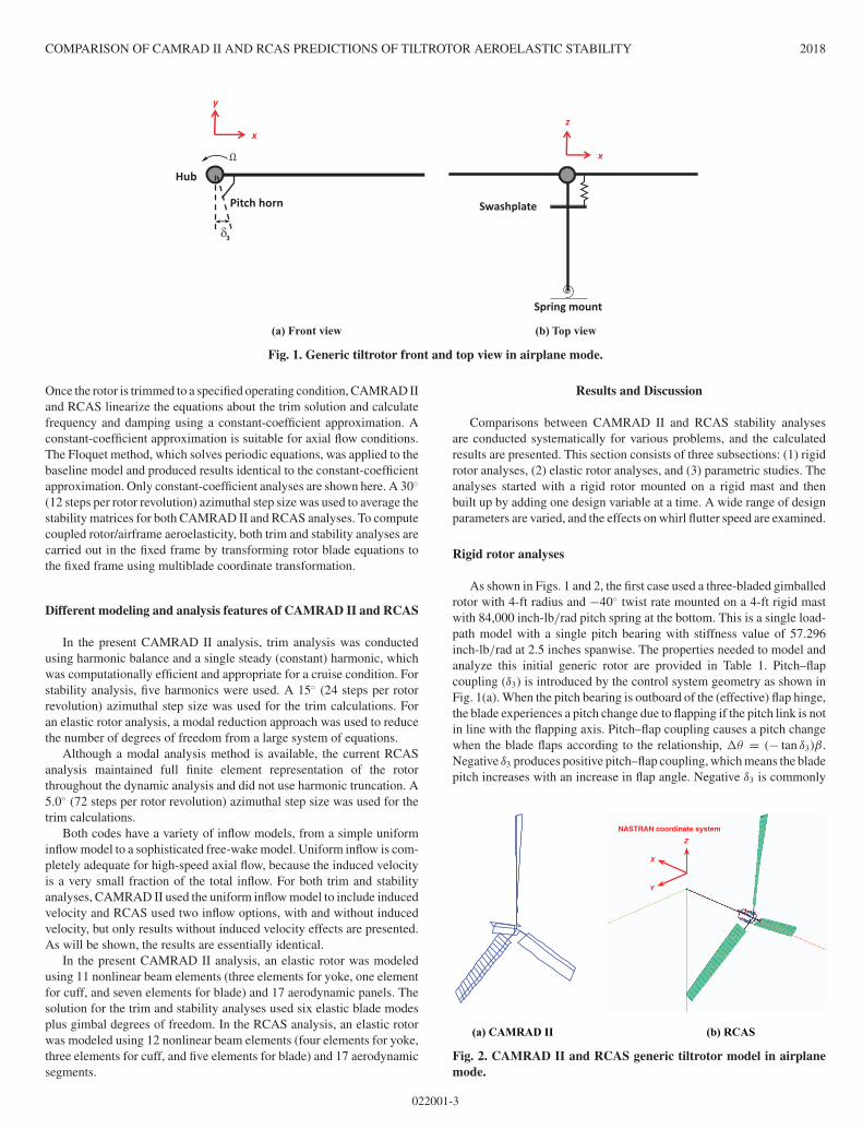
Fig. 1. Generic tiltrotor front and top view in airplane mode.
Once the rotor is trimmed to a specified operating condition, CAMRAD IIand RCAS linearize the equations about the trim solution and calculatefrequency and damping using a constant-coefficient approximation. Aconstant-coefficient approximation is suitable for axial flow conditions.The Floquet method, which solves periodic equations, was applied to thebaseline model and produced results identical to the constant-coefficientapproximation. Only constant-coefficient analyses are shown here. A 30◦
(12 steps per rotor revolution) azimuthal step size was used to average thestability matrices for both CAMRAD II and RCAS analyses. To computecoupled rotor/airframe aeroelasticity, both trim and stability analyses arecarried out in the fixed frame by transforming rotor blade equations tothe fixed frame using multiblade coordinate transformation.
Different modeling and analysis features of CAMRAD II and RCAS
In the present CAMRAD II analysis, trim analysis was conductedusing harmonic balance and a single steady (constant) harmonic, whichwas computationally efficient and appropriate for a cruise condition. Forstability analysis, five harmonics were used. A 15◦ (24 steps per rotorrevolution) azimuthal step size was used for the trim calculations. Foran elastic rotor analysis, a modal reduction approach was used to reducethe number of degrees of freedom from a large system of equations.
Although a modal analysis method is available, the current RCASanalysis maintained full finite element representation of the rotorthroughout the dynamic analysis and did not use harmonic truncation. A5.0◦ (72 steps per rotor revolution) azimuthal step size was used for thetrim calculations.
Both codes have a variety of inflow models, from a simple uniforminflow model to a sophisticated free-wake model. Uniform inflow is com-pletely adequate for high-speed axial flow, because the induced velocityis a very small fraction of the total inflow. For both trim and stabilityanalyses, CAMRAD II used the uniform inflow model to include inducedvelocity and RCAS used two inflow options, with and without inducedvelocity, but only results without induced velocity effects are presented.As will be shown, the results are essentially identical.
In the present CAMRAD II analysis, an elastic rotor was modeledusing 11 nonlinear beam elements (three elements for yoke, one elementfor cuff, and seven elements for blade) and 17 aerodynamic panels. Thesolution for the trim and stability analyses used six elastic blade modesplus gimbal degrees of freedom. In the RCAS analysis, an elastic rotorwas modeled using 12 nonlinear beam elements (four elements for yoke,three elements for cuff, and five elements for blade) and 17 aerodynamicsegments.
Results and Discussion
Comparisons between CAMRAD II and RCAS stability analysesare conducted systematically for various problems, and the calculatedresults are presented. This section consists of three subsections: (1) rigidrotor analyses, (2) elastic rotor analyses, and (3) parametric studies. Theanalyses started with a rigid rotor mounted on a rigid mast and thenbuilt up by adding one design variable at a time. A wide range of designparameters are varied, and the effects on whirl flutter speed are examined.
Rigid rotor analyses
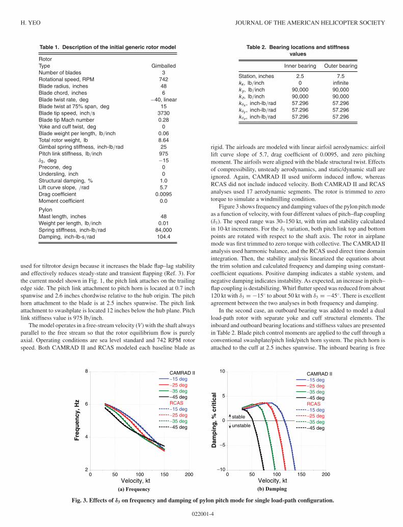
As shown in Figs. 1 and 2, the first case used a three-bladed gimballedrotor with 4-ft radius and −40◦ twist rate mounted on a 4-ft rigid mastwith 84,000 inch-lb/rad pitch spring at the bottom. This is a single load-path model with a single pitch bearing with stiffness value of 57.296inch-lb/rad at 2.5 inches spanwise. The properties needed to model andanalyze this initial generic rotor are provided in Table 1. Pitch–flapcoupling (δ3) is introduced by the control system geometry as shown inFig. 1(a). When the pitch bearing is outboard of the (effective) flap hinge,the blade experiences a pitch change due to flapping if the pitch link is notin line with the flapping axis. Pitch–flap coupling causes a pitch changewhen the blade flaps according to the relationship, �θ = (− tan δ3)β.Negative δ3 produces positive pitch–flap coupling, which means the bladepitch increases with an increase in flap angle. Negative δ3 is commonly
Z
X
Y
NASTRAN coordinate system
(a) CAMRAD II (b) RCAS
Fig. 2. CAMRAD II and RCAS generic tiltrotor model in airplanemode.
022001-3
H. YEO JOURNAL OF THE AMERICAN HELICOPTER SOCIETY
Table 1. Description of the initial generic rotor model
RotorType GimballedNumber of blades 3Rotational speed, RPM 742Blade radius, inches 48Blade chord, inches 6Blade twist rate, deg −40, linearBlade twist at 75% span, deg 15Blade tip speed, inch/s 3730Blade tip Mach number 0.28Yoke and cuff twist, deg 0Blade weight per length, lb/inch 0.06Total rotor weight, lb 8.64Gimbal spring stiffness, inch-lb/rad 25Pitch link stiffness, lb/inch 975δ3, deg −15Precone, deg 0Undersling, inch 0Structural damping, % 1.0Lift curve slope, /rad 5.7Drag coefficient 0.0095Moment coefficient 0.0
PylonMast length, inches 48Weight per length, lb/inch 0.01Spring stiffness, inch-lb/rad 84,000Damping, inch-lb-s/rad 104.4
used for tiltrotor design because it increases the blade flap–lag stabilityand effectively reduces steady-state and transient flapping (Ref. 3). Forthe current model shown in Fig. 1, the pitch link attaches on the trailingedge side. The pitch link attachment to pitch horn is located at 0.7 inchspanwise and 2.6 inches chordwise relative to the hub origin. The pitchhorn attachment to the blade is at 2.5 inches spanwise. The pitch linkattachment to swashplate is located 12 inches below the hub plane. Pitchlink stiffness value is 975 lb/inch.
The model operates in a free-stream velocity (V) with the shaft alwaysparallel to the free stream so that the rotor equilibrium flow is purelyaxial. Operating conditions are sea level standard and 742 RPM rotorspeed. Both CAMRAD II and RCAS modeled each baseline blade as
Table 2. Bearing locations and stiffnessvalues
Inner bearing Outer bearing
Station, inches 2.5 7.5kx, lb/inch 0 infiniteky, lb/inch 90,000 90,000kz, lb/inch 90,000 90,000k θx , inch-lb/rad 57.296 57.296k θy , inch-lb/rad 57.296 57.296k θz , inch-lb/rad 57.296 57.296
rigid. The airloads are modeled with linear airfoil aerodynamics: airfoillift curve slope of 5.7, drag coefficient of 0.0095, and zero pitchingmoment. The airfoils were aligned with the blade structural twist. Effectsof compressibility, unsteady aerodynamics, and static/dynamic stall areignored. Again, CAMRAD II used uniform induced inflow, whereasRCAS did not include induced velocity. Both CAMRAD II and RCASanalyses used 17 aerodynamic segments. The rotor is trimmed to zerotorque to simulate a windmilling condition.
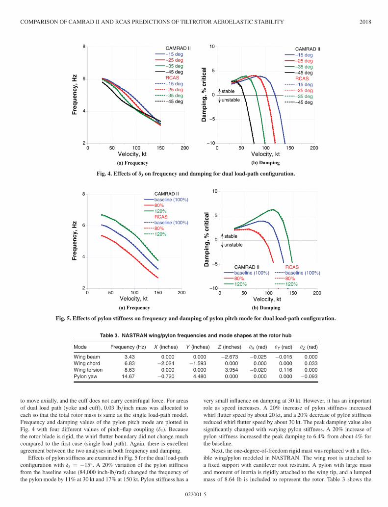
Figure 3 shows frequency and damping values of the pylon pitch modeas a function of velocity, with four different values of pitch–flap coupling(δ3). The speed range was 30–150 kt, with trim and stability calculatedin 10-kt increments. For the δ3 variation, both pitch link top and bottompoints are rotated with respect to the shaft axis. The rotor in airplanemode was first trimmed to zero torque with collective. The CAMRAD IIanalysis used harmonic balance, and the RCAS used direct time domainintegration. Then, the stability analysis linearized the equations aboutthe trim solution and calculated frequency and damping using constant-coefficient equations. Positive damping indicates a stable system, andnegative damping indicates instability. As expected, an increase in pitch–flap coupling is destabilizing. Whirl flutter speed was reduced from about120 kt with δ3 = −15◦ to about 50 kt with δ3 = −45◦. There is excellentagreement between the two analyses in both frequency and damping.
In the second case, an outboard bearing was added to model a dualload-path rotor with separate yoke and cuff structural elements. Theinboard and outboard bearing locations and stiffness values are presentedin Table 2. Blade pitch control moments are applied to the cuff through aconventional swashplate/pitch link/pitch horn system. The pitch horn isattached to the cuff at 2.5 inches spanwise. The inboard bearing is free
2
4
6
8
0 50 100 150 200
CAMRAD II−15 deg−25 deg−35 deg−45 degRCAS−15 deg−25 deg−35 deg−45 deg
Fre
qu
ency
, Hz
Velocity, kt
−10
−5
0
5
10
0 50 100 150 200
CAMRAD II−15 deg−25 deg−35 deg−45 degRCAS−15 deg−25 deg−35 deg−45 deg
Dam
pin
g, %
cri
tica
l
Velocity, kt
stable
unstable
(a) Frequency (b) Damping
Fig. 3. Effects of δ3 on frequency and damping of pylon pitch mode for single load-path configuration.
022001-4
COMPARISON OF CAMRAD II AND RCAS PREDICTIONS OF TILTROTOR AEROELASTIC STABILITY 2018
2
4
6
8
0 50 100 150 200
CAMRAD II−15 deg−25 deg−35 deg−45 degRCAS−15 deg−25 deg−35 deg−45 deg
Fre
qu
ency
, Hz
Velocity, kt
−10
−5
0
5
10
0 50 100 150 200
CAMRAD II−15 deg−25 deg−35 deg−45 degRCAS−15 deg−25 deg−35 deg−45 deg
Dam
pin
g, %
cri
tica
l
Velocity, kt
stable
unstable
(a) Frequency (b) Damping
Fig. 4. Effects of δ3 on frequency and damping for dual load-path configuration.
2
4
6
8
0 50 100 150 200
CAMRAD IIbaseline (100%)80%120%RCASbaseline (100%)80%120%
Fre
qu
ency
, Hz
Velocity, kt
−10
−5
0
5
10
0 50 100 150 200
CAMRAD IIbaseline (100%)80%120%
RCASbaseline (100%)80%120%
Dam
pin
g, %
cri
tica
l
Velocity, kt
stable
unstable
(a) Frequency (b) Damping
Fig. 5. Effects of pylon stiffness on frequency and damping of pylon pitch mode for dual load-path configuration.
Table 3. NASTRAN wing/pylon frequencies and mode shapes at the rotor hub
Mode Frequency (Hz) X (inches) Y (inches) Z (inches) θX (rad) θY (rad) θZ (rad)
Wing beam 3.43 0.000 0.000 −2.673 −0.025 −0.015 0.000Wing chord 6.83 −2.024 −1.593 0.000 0.000 0.000 0.033Wing torsion 8.63 0.000 0.000 3.954 −0.020 0.116 0.000Pylon yaw 14.67 −0.720 4.480 0.000 0.000 0.000 −0.093
to move axially, and the cuff does not carry centrifugal force. For areasof dual load path (yoke and cuff), 0.03 lb/inch mass was allocated toeach so that the total rotor mass is same as the single load-path model.Frequency and damping values of the pylon pitch mode are plotted inFig. 4 with four different values of pitch–flap coupling (δ3). Becausethe rotor blade is rigid, the whirl flutter boundary did not change muchcompared to the first case (single load path). Again, there is excellentagreement between the two analyses in both frequency and damping.
Effects of pylon stiffness are examined in Fig. 5 for the dual load-pathconfiguration with δ3 = −15◦. A 20% variation of the pylon stiffnessfrom the baseline value (84,000 inch-lb/rad) changed the frequency ofthe pylon mode by 11% at 30 kt and 17% at 150 kt. Pylon stiffness has a
very small influence on damping at 30 kt. However, it has an importantrole as speed increases. A 20% increase of pylon stiffness increasedwhirl flutter speed by about 20 kt, and a 20% decrease of pylon stiffnessreduced whirl flutter speed by about 30 kt. The peak damping value alsosignificantly changed with varying pylon stiffness. A 20% increase ofpylon stiffness increased the peak damping to 6.4% from about 4% forthe baseline.
Next, the one-degree-of-freedom rigid mast was replaced with a flex-ible wing/pylon modeled in NASTRAN. The wing root is attached toa fixed support with cantilever root restraint. A pylon with large massand moment of inertia is rigidly attached to the wing tip, and a lumpedmass of 8.64 lb is included to represent the rotor. Table 3 shows the
022001-5
H. YEO JOURNAL OF THE AMERICAN HELICOPTER SOCIETY
−4
0
4
8
0 50 100 150 200
CAMRAD IIBeamChordTorsionPy Yaw
RCASBeamChordTorsionPy Yaw
Dam
pin
g, %
cri
tica
l
Velocity, kt
stable
unstable
0
5
10
15
20
0 50 100 150 200
CAMRAD IIBeamChordTorsionPy Yaw
RCASBeamChordTorsionPy Yaw
Fre
qu
ency
, Hz
Velocity, kt(a) Frequency (b) Damping
Fig. 6. Frequency and damping of wing/pylon modes for rigid rotor configuration.
Table 4. Elastic rotor properties
Yoke flap stiffness at 0 inch, lb-inch2 36,000Yoke flap stiffness at 7.5 inches, lb-inch2 5040Yoke chord stiffness at 0 inch, lb-inch2 288,000Yoke chord stiffness at 7.5 inches, lb-inch2 100,800Yoke torsional stiffness, lb-inch2 1.008 × 10⁷, uniformCuff flap stiffness, lb-inch2 1.728 × 10⁶, uniformCuff chord stiffness, lb-inch2 1.728 × 10⁶, uniformCuff torsional stiffness, lb-inch2 1.008 ×10⁹, uniformBlade flap stiffness, lb-inch2 1.44 × 10⁷, uniformBlade chord stiffness, lb-inch2 1.44 × 10⁷, uniformBlade torsional stiffness, lb-inch2 1.008 ×10⁹, uniformSection flap moment of inertia, lb-s2 1.1 × 10⁻⁵, uniformSection chord moment of inertia, lb-s2 2.0 × 10⁻⁴, uniform
Pitch link stiffness, lb/inch 558.33
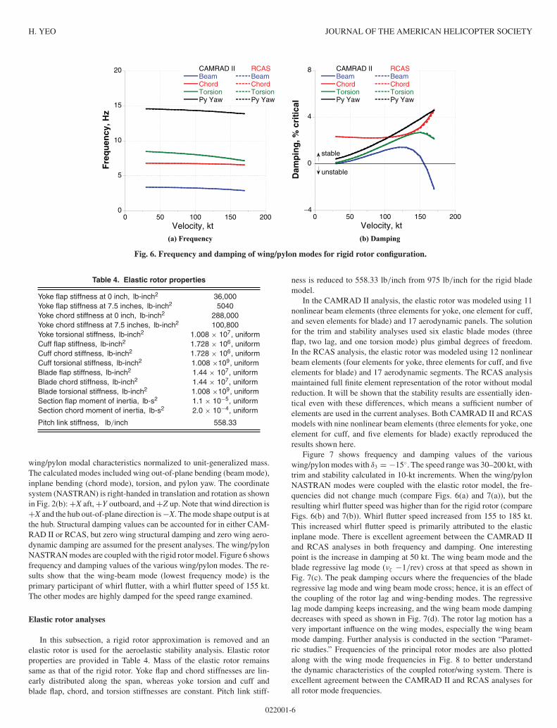
wing/pylon modal characteristics normalized to unit-generalized mass.The calculated modes included wing out-of-plane bending (beam mode),inplane bending (chord mode), torsion, and pylon yaw. The coordinatesystem (NASTRAN) is right-handed in translation and rotation as shownin Fig. 2(b): +X aft, +Y outboard, and +Z up. Note that wind direction is+X and the hub out-of-plane direction is −X. The mode shape output is atthe hub. Structural damping values can be accounted for in either CAM-RAD II or RCAS, but zero wing structural damping and zero wing aero-dynamic damping are assumed for the present analyses. The wing/pylonNASTRAN modes are coupled with the rigid rotor model. Figure 6 showsfrequency and damping values of the various wing/pylon modes. The re-sults show that the wing-beam mode (lowest frequency mode) is theprimary participant of whirl flutter, with a whirl flutter speed of 155 kt.The other modes are highly damped for the speed range examined.
Elastic rotor analyses
In this subsection, a rigid rotor approximation is removed and anelastic rotor is used for the aeroelastic stability analysis. Elastic rotorproperties are provided in Table 4. Mass of the elastic rotor remainssame as that of the rigid rotor. Yoke flap and chord stiffnesses are lin-early distributed along the span, whereas yoke torsion and cuff andblade flap, chord, and torsion stiffnesses are constant. Pitch link stiff-
ness is reduced to 558.33 lb/inch from 975 lb/inch for the rigid blademodel.
In the CAMRAD II analysis, the elastic rotor was modeled using 11nonlinear beam elements (three elements for yoke, one element for cuff,and seven elements for blade) and 17 aerodynamic panels. The solutionfor the trim and stability analyses used six elastic blade modes (threeflap, two lag, and one torsion mode) plus gimbal degrees of freedom.In the RCAS analysis, the elastic rotor was modeled using 12 nonlinearbeam elements (four elements for yoke, three elements for cuff, and fiveelements for blade) and 17 aerodynamic segments. The RCAS analysismaintained full finite element representation of the rotor without modalreduction. It will be shown that the stability results are essentially iden-tical even with these differences, which means a sufficient number ofelements are used in the current analyses. Both CAMRAD II and RCASmodels with nine nonlinear beam elements (three elements for yoke, oneelement for cuff, and five elements for blade) exactly reproduced theresults shown here.
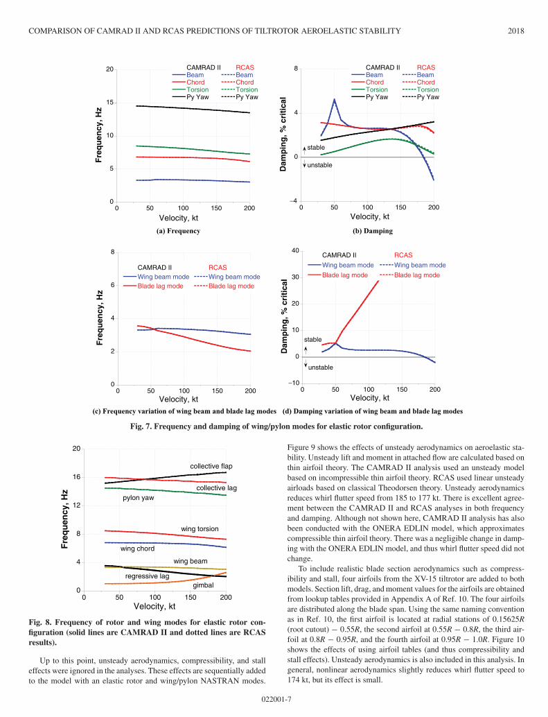
Figure 7 shows frequency and damping values of the variouswing/pylon modes with δ3 = −15◦. The speed range was 30–200 kt, withtrim and stability calculated in 10-kt increments. When the wing/pylonNASTRAN modes were coupled with the elastic rotor model, the fre-quencies did not change much (compare Figs. 6(a) and 7(a)), but theresulting whirl flutter speed was higher than for the rigid rotor (compareFigs. 6(b) and 7(b)). Whirl flutter speed increased from 155 to 185 kt.This increased whirl flutter speed is primarily attributed to the elasticinplane mode. There is excellent agreement between the CAMRAD IIand RCAS analyses in both frequency and damping. One interestingpoint is the increase in damping at 50 kt. The wing beam mode and theblade regressive lag mode (νζ −1/rev) cross at that speed as shown inFig. 7(c). The peak damping occurs where the frequencies of the bladeregressive lag mode and wing beam mode cross; hence, it is an effect ofthe coupling of the rotor lag and wing-bending modes. The regressivelag mode damping keeps increasing, and the wing beam mode dampingdecreases with speed as shown in Fig. 7(d). The rotor lag motion has avery important influence on the wing modes, especially the wing beammode damping. Further analysis is conducted in the section “Paramet-ric studies.” Frequencies of the principal rotor modes are also plottedalong with the wing mode frequencies in Fig. 8 to better understandthe dynamic characteristics of the coupled rotor/wing system. There isexcellent agreement between the CAMRAD II and RCAS analyses forall rotor mode frequencies.
022001-6
COMPARISON OF CAMRAD II AND RCAS PREDICTIONS OF TILTROTOR AEROELASTIC STABILITY 2018
0
2
4
6
8
0 50 100 150 200
CAMRAD IIWing beam modeBlade lag mode
RCASWing beam modeBlade lag mode
Fre
qu
ency
, Hz
Velocity, kt
0
5
10
15
20
0 50 100 150 200
CAMRAD IIBeamChordTorsionPy Yaw
RCASBeamChordTorsionPy Yaw
Fre
qu
ency
, Hz
−10
0
10
20
30
40
0 50 100 150 200
CAMRAD II
Wing beam mode
Blade lag mode
RCAS
Wing beam mode
Blade lag modeD
amp
ing
, % c
riti
cal
Velocity, kt
Velocity, kt Velocity, kt
stable
unstable
−4
0
4
8
0 50 100 150 200
CAMRAD IIBeamChordTorsionPy Yaw
RCASBeamChordTorsionPy Yaw
Dam
pin
g, %
cri
tica
l
stable
unstable
(a) Frequency (b) Damping
(c) Frequency variation of wing beam and blade lag modes (d) Damping variation of wing beam and blade lag modes
Fig. 7. Frequency and damping of wing/pylon modes for elastic rotor configuration.
0
4
8
12
16
20
0 50 100 150 200
Fre
qu
ency
, Hz
Velocity, kt
gimbalregressive lag
wing beam
wing chord
wing torsion
pylon yaw
collective flap
collective lag
Fig. 8. Frequency of rotor and wing modes for elastic rotor con-figuration (solid lines are CAMRAD II and dotted lines are RCASresults).
Up to this point, unsteady aerodynamics, compressibility, and stalleffects were ignored in the analyses. These effects are sequentially addedto the model with an elastic rotor and wing/pylon NASTRAN modes.
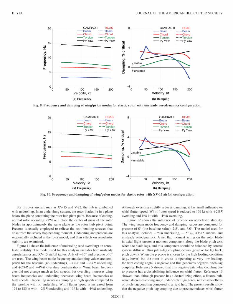
Figure 9 shows the effects of unsteady aerodynamics on aeroelastic sta-bility. Unsteady lift and moment in attached flow are calculated based onthin airfoil theory. The CAMRAD II analysis used an unsteady modelbased on incompressible thin airfoil theory. RCAS used linear unsteadyairloads based on classical Theodorsen theory. Unsteady aerodynamicsreduces whirl flutter speed from 185 to 177 kt. There is excellent agree-ment between the CAMRAD II and RCAS analyses in both frequencyand damping. Although not shown here, CAMRAD II analysis has alsobeen conducted with the ONERA EDLIN model, which approximatescompressible thin airfoil theory. There was a negligible change in damp-ing with the ONERA EDLIN model, and thus whirl flutter speed did notchange.
To include realistic blade section aerodynamics such as compress-ibility and stall, four airfoils from the XV-15 tiltrotor are added to bothmodels. Section lift, drag, and moment values for the airfoils are obtainedfrom lookup tables provided in Appendix A of Ref. 10. The four airfoilsare distributed along the blade span. Using the same naming conventionas in Ref. 10, the first airfoil is located at radial stations of 0.15625R(root cutout) − 0.55R, the second airfoil at 0.55R − 0.8R, the third air-foil at 0.8R − 0.95R, and the fourth airfoil at 0.95R − 1.0R. Figure 10shows the effects of using airfoil tables (and thus compressibility andstall effects). Unsteady aerodynamics is also included in this analysis. Ingeneral, nonlinear aerodynamics slightly reduces whirl flutter speed to174 kt, but its effect is small.
022001-7
H. YEO JOURNAL OF THE AMERICAN HELICOPTER SOCIETY
−4
0
4
8
0 50 100 150 200
CAMRAD IIBeamChordTorsionPy Yaw
RCASBeamChordTorsionPy Yaw
Dam
pin
g, %
cri
tica
l
Velocity, kt
stable
unstable
0
5
10
15
20
0 50 100 150 200
CAMRAD IIBeamChordTorsionPy Yaw
RCASBeamChordTorsionPy Yaw
Fre
qu
ency
, Hz
Velocity, kt
(a) Frequency (b) Damping
Fig. 9. Frequency and damping of wing/pylon modes for elastic rotor with unsteady aerodynamics configuration.
−4
0
4
8
0 50 100 150 200
CAMRAD IIBeamChordTorsionPy Yaw
RCASBeamChordTorsionPy Yaw
Dam
pin
g, %
cri
tica
l
Velocity, kt
stable
unstable
0
5
10
15
20
0 50 100 150 200
CAMRAD IIBeamChordTorsionPy Yaw
RCASBeamChordTorsionPy Yaw
Fre
qu
ency
, Hz
Velocity, kt(a) Frequency (b) Damping
Fig. 10. Frequency and damping of wing/pylon modes for elastic rotor with XV-15 airfoil configuration.
For tiltrotor aircraft such as XV-15 and V-22, the hub is gimballedwith undersling. In an underslung system, the rotor blades lie in a planebelow the plane containing the rotor hub pivot point. Because of coning,normal rotor operating RPM will place the center of mass of the rotorblades in approximately the same plane as the rotor hub pivot point.Precone is usually employed to relieve the root-bending stresses thatarise from the steady flap bending moment. Undersling and precone aresequentially included in the rotor model, and their effects on aeroelasticstability are examined.
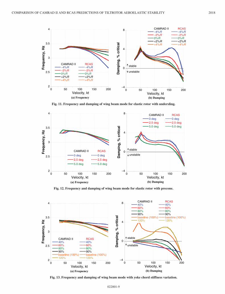
Figure 11 shows the influence of undersling (and oversling) on aeroe-lastic stability. The model used for this analysis includes both unsteadyaerodynamics and XV-15 airfoil tables. A δ3 of −15◦ and precone of 0◦
are used. The wing beam mode frequency and damping values are com-pared for the baseline (no undersling), −4%R and −2%R undersling,and +2%R and +4%R oversling configurations. Wing beam frequen-cies did not change much at low speeds, but oversling increases wingbeam frequencies and undersling decreases wing beam frequencies athigh speeds. Undersling increases damping at high speeds compared tothe baseline with no undersling. Whirl flutter speed is increased from174 to 183 kt with −2%R undersling and 196 kt with −4%R undersling.
Although oversling slightly reduces damping, it has small influence onwhirl flutter speed. Whirl flutter speed is reduced to 169 kt with +2%Roversling and 168 kt with +4%R oversling.
Figure 12 shows the influence of precone on aeroelastic stability.The wing beam mode frequency and damping values are compared forprecone of 0◦ (the baseline value), 2.5◦, and 5.0◦. The model used forthis analysis includes −2%R undersling, −15◦ δ3, XV-15 airfoils, andunsteady aerodynamics. A net flap moment acting on the rotor bladein axial flight creates a moment component along the blade pitch axiswhen the blade lags, and this component should be balanced by controlsystem stiffness. Thus pitch–lag coupling occurs (positive for lag back,pitch down). When the precone is chosen for the high loading condition(e.g., hover) but the rotor in cruise is operating at very low loading,the trim coning angle is negative and this generates negative pitch–lagcoupling. Reference 5 showed that this negative pitch–lag coupling dueto precone has a destabilizing influence on whirl flutter. Reference 13showed that, although precone has a destabilizing effect, a flexure hub,which decreases coning angle under centrifugal force, reduces the effectsof pitch–lag coupling compared to a rigid hub. The present results showthat the negative pitch–lag coupling due to precone reduces whirl flutter
022001-8
COMPARISON OF CAMRAD II AND RCAS PREDICTIONS OF TILTROTOR AEROELASTIC STABILITY 2018
−4
0
4
8
0 50 100 150 200
CAMRAD II−4%R−2%R0%R+2%R+4%R
RCAS−4%R−2%R0%R+2%R+4%R
Dam
pin
g, %
cri
tica
l
Velocity, kt
stable
unstable
2
2.5
3
3.5
4
0 50 100 150 200
CAMRAD II−4%R−2%R0%R+2%R+4%R
RCAS−4%R−2%R0%R+2%R+4%R
Fre
qu
ency
, Hz
Velocity, kt(a) Frequency (b) Damping
Fig. 11. Frequency and damping of wing beam mode for elastic rotor with undersling.
−4
0
4
8
0 50 100 150 200
CAMRAD II0 deg2.5 deg5.0 deg
RCAS0 deg2.5 deg5.0 deg
Dam
pin
g, %
cri
tica
l
Velocity, kt
stable
unstable
2
2.5
3
3.5
4
0 50 100 150 200
CAMRAD II
0 deg
2.5 deg
5.0 deg
RCAS
0 deg
2.5 deg
5.0 deg
Fre
qu
ency
, Hz
Velocity, kt(a) Frequency (b) Damping
Fig. 12. Frequency and damping of wing beam mode for elastic rotor with precone.
−4
0
4
8
0 50 100 150 200
CAMRAD II40%60%80%90%baseline (100%)120%
RCAS40%60%80%90%baseline (100%)120%
Dam
pin
g, %
cri
tica
l
Velocity, kt
stable
unstable
2
2.5
3
3.5
4
0 50 100 150 200
CAMRAD II40%60%80%90%baseline (100%)120%
RCAS40%60%80%90%baseline (100%)120%
Fre
qu
ency
, Hz
Velocity, kt(a) Frequency (b) Damping
Fig. 13. Frequency and damping of wing beam mode with yoke chord stiffness variation.
022001-9
H. YEO JOURNAL OF THE AMERICAN HELICOPTER SOCIETY
0
2
4
6
8
0 50 100 150 200
Wing beam mode40%60%80%90%baseline (100%)120%
Blade lag mode40%60%80%90%baseline (100%)120%
Fre
qu
ency
, Hz
Velocity, kt
Fig. 14. Comparison between wing beam mode and blade lag modefrequencies with yoke chord stiffness variation (RCAS analysis).
speed, which is consistent with the results in Refs. 5 and 13. Whirl flutterspeed is reduced from 183 kt for the baseline (0◦ precone) to 176 kt forthe 2.5◦ precone and to 169 kt for the 5.0◦ precone.
Parametric studies
Starting with a simple rigid rotor mounted on a rigid pylon, a moresophisticated model was built up by adding one design variable at a time.The three-bladed gimballed rotor with dual load path, elastic blades,−2%R undersling, 2.5◦ precone, −15◦ δ3, and XV-15 airfoils includesall the key design parameters of realistic tiltrotor configurations. Therotor is coupled with the flexible wing/pylon modeled from NASTRANfor aeroelastic stability analysis. Parametric studies are conducted in thissubsection using this model as a baseline. The parameters investigatedin this study are yoke chord and flap stiffness, pitch link stiffness, pitch–flap coupling (δ3), rotor rotational speed, density, and speed of sound.The effects of those parameters on the wing beam mode frequency anddamping are examined.
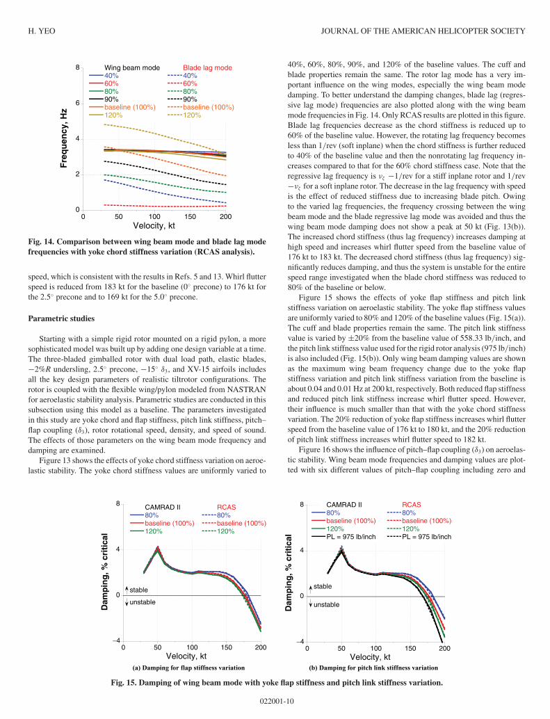
Figure 13 shows the effects of yoke chord stiffness variation on aeroe-lastic stability. The yoke chord stiffness values are uniformly varied to
40%, 60%, 80%, 90%, and 120% of the baseline values. The cuff andblade properties remain the same. The rotor lag mode has a very im-portant influence on the wing modes, especially the wing beam modedamping. To better understand the damping changes, blade lag (regres-sive lag mode) frequencies are also plotted along with the wing beammode frequencies in Fig. 14. Only RCAS results are plotted in this figure.Blade lag frequencies decrease as the chord stiffness is reduced up to60% of the baseline value. However, the rotating lag frequency becomesless than 1/rev (soft inplane) when the chord stiffness is further reducedto 40% of the baseline value and then the nonrotating lag frequency in-creases compared to that for the 60% chord stiffness case. Note that theregressive lag frequency is νζ −1/rev for a stiff inplane rotor and 1/rev−νζ for a soft inplane rotor. The decrease in the lag frequency with speedis the effect of reduced stiffness due to increasing blade pitch. Owingto the varied lag frequencies, the frequency crossing between the wingbeam mode and the blade regressive lag mode was avoided and thus thewing beam mode damping does not show a peak at 50 kt (Fig. 13(b)).The increased chord stiffness (thus lag frequency) increases damping athigh speed and increases whirl flutter speed from the baseline value of176 kt to 183 kt. The decreased chord stiffness (thus lag frequency) sig-nificantly reduces damping, and thus the system is unstable for the entirespeed range investigated when the blade chord stiffness was reduced to80% of the baseline or below.
Figure 15 shows the effects of yoke flap stiffness and pitch linkstiffness variation on aeroelastic stability. The yoke flap stiffness valuesare uniformly varied to 80% and 120% of the baseline values (Fig. 15(a)).The cuff and blade properties remain the same. The pitch link stiffnessvalue is varied by ±20% from the baseline value of 558.33 lb/inch, andthe pitch link stiffness value used for the rigid rotor analysis (975 lb/inch)is also included (Fig. 15(b)). Only wing beam damping values are shownas the maximum wing beam frequency change due to the yoke flapstiffness variation and pitch link stiffness variation from the baseline isabout 0.04 and 0.01 Hz at 200 kt, respectively. Both reduced flap stiffnessand reduced pitch link stiffness increase whirl flutter speed. However,their influence is much smaller than that with the yoke chord stiffnessvariation. The 20% reduction of yoke flap stiffness increases whirl flutterspeed from the baseline value of 176 kt to 180 kt, and the 20% reductionof pitch link stiffness increases whirl flutter speed to 182 kt.
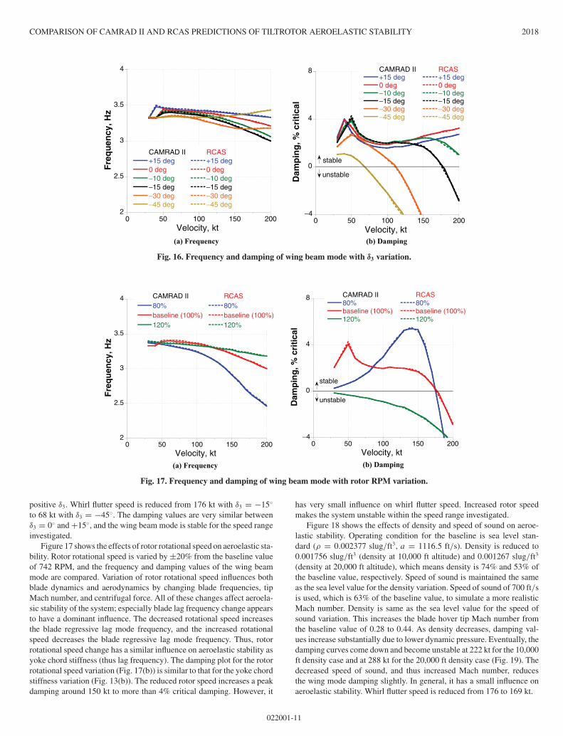
Figure 16 shows the influence of pitch–flap coupling (δ3) on aeroelas-tic stability. Wing beam mode frequencies and damping values are plot-ted with six different values of pitch–flap coupling including zero and
−4
0
4
8
0 50 100 150 200
CAMRAD II80%baseline (100%)120%PL = 975 lb/inch
RCAS80%baseline (100%)120%PL = 975 lb/inch
Dam
pin
g, %
cri
tica
l
Velocity, kt
stable
unstable
−4
0
4
8
0 50 100 150 200
CAMRAD II80%baseline (100%)120%
RCAS80%baseline (100%)120%
Dam
pin
g, %
cri
tica
l
Velocity, kt
stable
unstable
(a) Damping for flap stiffness variation (b) Damping for pitch link stiffness variation
Fig. 15. Damping of wing beam mode with yoke flap stiffness and pitch link stiffness variation.
022001-10
COMPARISON OF CAMRAD II AND RCAS PREDICTIONS OF TILTROTOR AEROELASTIC STABILITY 2018
−4
0
4
8
0 50 100 150 200
CAMRAD II+15 deg0 deg−10 deg−15 deg−30 deg−45 deg
RCAS+15 deg0 deg−10 deg−15 deg−30 deg−45 deg
Dam
pin
g, %
cri
tica
l
Velocity, kt
stable
unstable
2
2.5
3
3.5
4
0 50 100 150 200
CAMRAD II+15 deg0 deg−10 deg−15 deg−30 deg−45 deg
RCAS+15 deg0 deg−10 deg−15 deg−30 deg−45 deg
Fre
qu
ency
, Hz
Velocity, kt
(a) Frequency (b) Damping
Fig. 16. Frequency and damping of wing beam mode with δ3 variation.
−4
0
4
8
0 50 100 150 200
CAMRAD II80%baseline (100%)120%
RCAS80%baseline (100%)120%
Dam
pin
g, %
cri
tica
l
Velocity, kt
stable
unstable
2
2.5
3
3.5
4
0 50 100 150 200
CAMRAD II80%baseline (100%)120%
RCAS80%baseline (100%)120%
Fre
qu
ency
, Hz
Velocity, kt(a) Frequency (b) Damping
Fig. 17. Frequency and damping of wing beam mode with rotor RPM variation.
positive δ3. Whirl flutter speed is reduced from 176 kt with δ3 = −15◦
to 68 kt with δ3 = −45◦. The damping values are very similar betweenδ3 = 0◦ and +15◦, and the wing beam mode is stable for the speed rangeinvestigated.
Figure 17 shows the effects of rotor rotational speed on aeroelastic sta-bility. Rotor rotational speed is varied by ±20% from the baseline valueof 742 RPM, and the frequency and damping values of the wing beammode are compared. Variation of rotor rotational speed influences bothblade dynamics and aerodynamics by changing blade frequencies, tipMach number, and centrifugal force. All of these changes affect aeroela-sic stability of the system; especially blade lag frequency change appearsto have a dominant influence. The decreased rotational speed increasesthe blade regressive lag mode frequency, and the increased rotationalspeed decreases the blade regressive lag mode frequency. Thus, rotorrotational speed change has a similar influence on aeroelastic stability asyoke chord stiffness (thus lag frequency). The damping plot for the rotorrotational speed variation (Fig. 17(b)) is similar to that for the yoke chordstiffness variation (Fig. 13(b)). The reduced rotor speed increases a peakdamping around 150 kt to more than 4% critical damping. However, it
has very small influence on whirl flutter speed. Increased rotor speedmakes the system unstable within the speed range investigated.
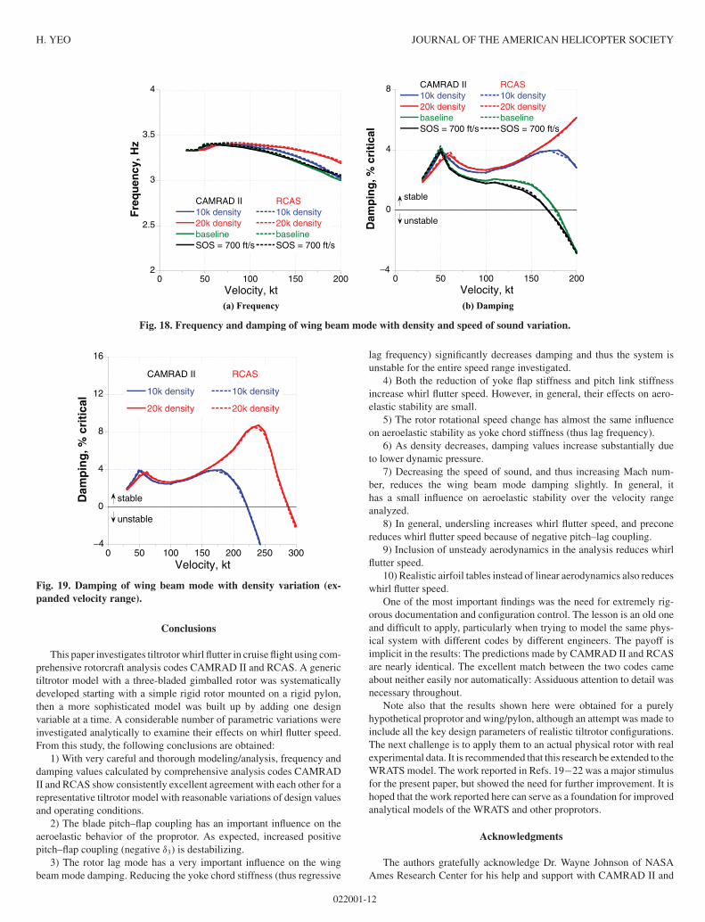
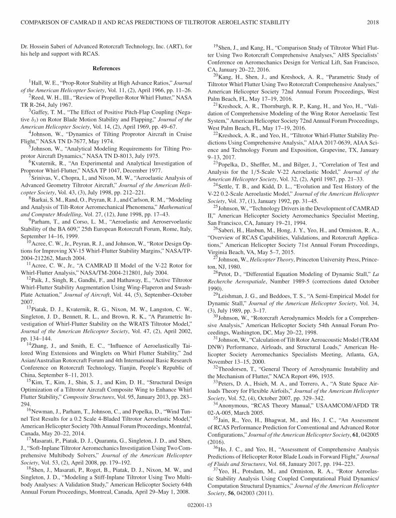
Figure 18 shows the effects of density and speed of sound on aeroe-lastic stability. Operating condition for the baseline is sea level stan-dard (ρ = 0.002377 slug/ft3, a = 1116.5 ft/s). Density is reduced to0.001756 slug/ft3 (density at 10,000 ft altitude) and 0.001267 slug/ft3
(density at 20,000 ft altitude), which means density is 74% and 53% ofthe baseline value, respectively. Speed of sound is maintained the sameas the sea level value for the density variation. Speed of sound of 700 ft/sis used, which is 63% of the baseline value, to simulate a more realisticMach number. Density is same as the sea level value for the speed ofsound variation. This increases the blade hover tip Mach number fromthe baseline value of 0.28 to 0.44. As density decreases, damping val-ues increase substantially due to lower dynamic pressure. Eventually, thedamping curves come down and become unstable at 222 kt for the 10,000ft density case and at 288 kt for the 20,000 ft density case (Fig. 19). Thedecreased speed of sound, and thus increased Mach number, reducesthe wing mode damping slightly. In general, it has a small influence onaeroelastic stability. Whirl flutter speed is reduced from 176 to 169 kt.
022001-11
H. YEO JOURNAL OF THE AMERICAN HELICOPTER SOCIETY
2
2.5
3
3.5
4
0 50 100 150 200
CAMRAD II10k density20k densitybaselineSOS = 700 ft/s
RCAS10k density20k densitybaselineSOS = 700 ft/s
Fre
qu
ency
, Hz
Velocity, kt
−4
0
4
8
0 50 100 150 200
CAMRAD II10k density20k densitybaselineSOS = 700 ft/s
RCAS10k density20k densitybaselineSOS = 700 ft/s
Dam
pin
g, %
cri
tica
l
Velocity, kt
stable
unstable
(a) Frequency (b) Damping
Fig. 18. Frequency and damping of wing beam mode with density and speed of sound variation.
−4
0
4
8
12
16
0 50 100 150 200 250 300
CAMRAD II
10k density
20k density
RCAS
10k density
20k density
Dam
pin
g, %
cri
tica
l
Velocity, kt
stable
unstable
Fig. 19. Damping of wing beam mode with density variation (ex-panded velocity range).
Conclusions
This paper investigates tiltrotor whirl flutter in cruise flight using com-prehensive rotorcraft analysis codes CAMRAD II and RCAS. A generictiltrotor model with a three-bladed gimballed rotor was systematicallydeveloped starting with a simple rigid rotor mounted on a rigid pylon,then a more sophisticated model was built up by adding one designvariable at a time. A considerable number of parametric variations wereinvestigated analytically to examine their effects on whirl flutter speed.From this study, the following conclusions are obtained:
1) With very careful and thorough modeling/analysis, frequency anddamping values calculated by comprehensive analysis codes CAMRADII and RCAS show consistently excellent agreement with each other for arepresentative tiltrotor model with reasonable variations of design valuesand operating conditions.
2) The blade pitch–flap coupling has an important influence on theaeroelastic behavior of the proprotor. As expected, increased positivepitch–flap coupling (negative δ3) is destabilizing.
3) The rotor lag mode has a very important influence on the wingbeam mode damping. Reducing the yoke chord stiffness (thus regressive
lag frequency) significantly decreases damping and thus the system isunstable for the entire speed range investigated.
4) Both the reduction of yoke flap stiffness and pitch link stiffnessincrease whirl flutter speed. However, in general, their effects on aero-elastic stability are small.
5) The rotor rotational speed change has almost the same influenceon aeroelastic stability as yoke chord stiffness (thus lag frequency).
6) As density decreases, damping values increase substantially dueto lower dynamic pressure.
7) Decreasing the speed of sound, and thus increasing Mach num-ber, reduces the wing beam mode damping slightly. In general, ithas a small influence on aeroelastic stability over the velocity rangeanalyzed.
8) In general, undersling increases whirl flutter speed, and preconereduces whirl flutter speed because of negative pitch–lag coupling.
9) Inclusion of unsteady aerodynamics in the analysis reduces whirlflutter speed.
10) Realistic airfoil tables instead of linear aerodynamics also reduceswhirl flutter speed.
One of the most important findings was the need for extremely rig-orous documentation and configuration control. The lesson is an old oneand difficult to apply, particularly when trying to model the same phys-ical system with different codes by different engineers. The payoff isimplicit in the results: The predictions made by CAMRAD II and RCASare nearly identical. The excellent match between the two codes cameabout neither easily nor automatically: Assiduous attention to detail wasnecessary throughout.
Note also that the results shown here were obtained for a purelyhypothetical proprotor and wing/pylon, although an attempt was made toinclude all the key design parameters of realistic tiltrotor configurations.The next challenge is to apply them to an actual physical rotor with realexperimental data. It is recommended that this research be extended to theWRATS model. The work reported in Refs. 19−22 was a major stimulusfor the present paper, but showed the need for further improvement. It ishoped that the work reported here can serve as a foundation for improvedanalytical models of the WRATS and other proprotors.
Acknowledgments
The authors gratefully acknowledge Dr. Wayne Johnson of NASAAmes Research Center for his help and support with CAMRAD II and
022001-12
COMPARISON OF CAMRAD II AND RCAS PREDICTIONS OF TILTROTOR AEROELASTIC STABILITY 2018
Dr. Hossein Saberi of Advanced Rotorcraft Technology, Inc. (ART), forhis help and support with RCAS.
References
1Hall, W. E., “Prop-Rotor Stability at High Advance Ratios,” Journalof the American Helicopter Society, Vol. 11, (2), April 1966, pp. 11–26.
2Reed, W. H., III., “Review of Propeller-Rotor Whirl Flutter,” NASATR R-264, July 1967.
3Gaffey, T. M., “The Effect of Positive Pitch-Flap Coupling (Nega-tive δ3) on Rotor Blade Motion Stability and Flapping,” Journal of theAmerican Helicopter Society, Vol. 14, (2), April 1969, pp. 49–67.
4Johnson, W., “Dynamics of Tilting Proprotor Aircraft in CruiseFlight,” NASA TN D-7677, May 1974.
5Johnson, W., “Analytical Modeling Requirements for Tilting Pro-protor Aircraft Dynamics,” NASA TN D-8013, July 1975.
6Kvaternik, R., “An Experimental and Analytical Investigation ofProprotor Whirl-Flutter,” NASA TP 1047, December 1977.
7Srinivas, V., Chopra, I., and Nixon, M. W., “Aeroelastic Analysis ofAdvanced Geometry Tiltrotor Aircraft,” Journal of the American Heli-copter Society, Vol. 43, (3), July 1998, pp. 212–221.
8Barkai, S. M., Rand, O., Peyran, R. J., and Carlson, R. M., “Modelingand Analysis of Tilt-Rotor Aeromechanical Phenomena,” Mathematicaland Computer Modelling, Vol. 27, (12), June 1998, pp. 17–43.
9Parham, T., and Corso, L. M., “Aeroelastic and AeroservoelasticStability of the BA 609,” 25th European Rotorcraft Forum, Rome, Italy,September 14–16, 1999.
10Acree, C. W., Jr., Peyran, R. J., and Johnson, W., “Rotor Design Op-tions for Improving XV-15 Whirl-Flutter Stability Margins,” NASA/TP-2004-212262, March 2004.
11Acree, C. W., Jr., “A CAMRAD II Model of the V-22 Rotor forWhirl-Flutter Analysis,” NASA/TM-2004-212801, July 2004.
12Paik, J., Singh, R., Gandhi, F., and Hathaway, E., “Active TiltrotorWhirl-Flutter Stability Augmentation Using Wing-Flaperon and Swash-Plate Actuation,” Journal of Aircraft, Vol. 44, (5), September–October2007.
13Piatak, D. J., Kvaternik, R. G., Nixon, M. W., Langston, C. W.,Singleton, J. D., Bennett, R. L., and Brown, R. K., “A Parametric In-vestigation of Whirl-Flutter Stability on the WRATS Tiltrotor Model,”Journal of the American Helicopter Society, Vol. 47, (2), April 2002,pp. 134–144.
14Zhang, J., and Smith, E. C., “Influence of Aeroelastically Tai-lored Wing Extensions and Winglets on Whirl Flutter Stability,” 2ndAsian/Australian Rotorcraft Forum and 4th International Basic ResearchConference on Rotorcraft Technology, Tianjin, People’s Republic ofChina, September 8–11, 2013.
15Kim, T., Kim, J., Shin, S. J., and Kim, D. H., “Structural DesignOptimization of a Tiltrotor Aircraft Composite Wing to Enhance WhirlFlutter Stability,” Composite Structures, Vol. 95, January 2013, pp. 283–294.
16Newman, J., Parham, T., Johnson, C., and Popelka, D., “Wind Tun-nel Test Results for a 0.2 Scale 4-Bladed Tiltrotor Aeroelastic Model,”American Helicopter Society 70th Annual Forum Proceedings, Montreal,Canada, May 20–22, 2014.
17Masarati, P., Piatak, D. J., Quaranta, G., Singleton, J. D., and Shen,J., “Soft-Inplane Tiltrotor Aeromechanics Investigation Using Two Com-prehensive Multibody Solvers,” Journal of the American HelicopterSociety, Vol. 53, (2), April 2008, pp. 179–192.
18Shen, J., Masarati, P., Roget, B., Piatak, D. J., Nixon, M. W., andSingleton, J. D., “Modeling a Stiff-Inplane Tiltrotor Using Two Multi-body Analyses: A Validation Study,” American Helicopter Society 64thAnnual Forum Proceedings, Montreal, Canada, April 29–May 1, 2008.
19Shen, J., and Kang, H., “Comparison Study of Tiltrotor Whirl Flut-ter Using Two Rotorcraft Comprehensive Analyses,” AHS Specialists’Conference on Aeromechanics Design for Vertical Lift, San Francisco,CA, January 20–22, 2016.
20Kang, H., Shen, J., and Kreshock, A. R., “Parametric Study ofTiltrotor Whirl Flutter Using Two Rotorcraft Comprehensive Analyses,”American Helicopter Society 72nd Annual Forum Proceedings, WestPalm Beach, FL, May 17–19, 2016.
21Kreshock, A. R., Thornburgh, R. P., Kang, H., and Yeo, H., “Vali-dation of Comprehensive Modeling of the Wing Rotor Aeroelastic TestSystem,” American Helicopter Society 72nd Annual Forum Proceedings,West Palm Beach, FL, May 17–19, 2016.
22Kreshock, A. R., and Yeo, H., “Tiltrotor Whirl-Flutter Stability Pre-dictions Using Comprehensive Analysis,” AIAA 2017-0639, AIAA Sci-ence and Technology Forum and Exposition, Grapevine, TX, January9–13, 2017.
23Popelka, D., Sheffler, M., and Bilger, J., “Correlation of Test andAnalysis for the 1/5-Scale V-22 Aeroelastic Model,” Journal of theAmerican Helicopter Society, Vol. 32, (2), April 1987, pp. 21–33.
24Settle, T. B., and Kidd, D. L., “Evolution and Test History of theV-22 0.2-Scale Aeroelastic Model,” Journal of the American HelicopterSociety, Vol. 37, (1), January 1992, pp. 31–45.
25Johnson, W., “Technology Drivers in the Development of CAMRADII,” American Helicopter Society Aeromechanics Specialist Meeting,San Francisco, CA, January 19–21, 1994.
26Saberi, H., Hasbun, M., Hong, J. Y., Yeo, H., and Ormiston, R. A.,“Overview of RCAS Capabilities, Validations, and Rotorcraft Applica-tions,” American Helicopter Society 71st Annual Forum Proceedings,Virginia Beach, VA, May 5–7, 2015.
27Johnson, W., Helicopter Theory, Princeton University Press, Prince-ton, NJ, 1980.
28Petot, D., “Differential Equation Modeling of Dynamic Stall,” LaRecherche Aerospatiale, Number 1989-5 (corrections dated October1990).
29Leishman, J. G., and Beddoes, T. S., “A Semi-Empirical Model forDynamic Stall,” Journal of the American Helicopter Society, Vol. 34,(3), July 1989, pp. 3–17.
30Johnson, W., “Rotorcraft Aerodynamics Models for a Comprehen-sive Analysis,” American Helicopter Society 54th Annual Forum Pro-ceedings, Washington, DC, May 20–22, 1998.
31Johnson, W., “Calculation of Tilt Rotor Aeroacoustic Model (TRAMDNW) Performance, Airloads, and Structural Loads,” American He-licopter Society Aeromechanics Specialists Meeting, Atlanta, GA,November 13–15, 2000.
32Theodorsen, T., “General Theory of Aerodynamic Instability andthe Mechanism of Flutter,” NACA Report 496, 1935.
33Peters, D. A., Hsieh, M. A., and Torrero, A., “A State Space Air-loads Theory for Flexible Airfoils,” Journal of the American HelicopterSociety, Vol. 52, (4), October 2007, pp. 329–342.
34Anonymous, “RCAS Theory Manual,” USAAMCOM/AFDD TR02-A-005, March 2005.
35Jain, R., Yeo, H., Bhagwat, M., and Ho, J. C., “An Assessmentof RCAS Performance Prediction for Conventional and Advanced RotorConfigurations,” Journal of the American Helicopter Society, 61, 042005(2016).
36Ho, J. C., and Yeo, H., “Assessment of Comprehensive AnalysisPredictions of Helicopter Rotor Blade Loads in Forward Flight,” Journalof Fluids and Structures, Vol. 68, January 2017, pp. 194–223.
37Yeo, H., Potsdam, M., and Ormiston, R. A., “Rotor Aeroelas-tic Stability Analysis Using Coupled Computational Fluid Dynamics/Computation Structural Dynamics,” Journal of the American HelicopterSociety, 56, 042003 (2011).
022001-13