COMPANY PROFILE - Scientific Components
174
Transcript of COMPANY PROFILE - Scientific Components
COMPANY PROFILE
ACTIVITIES OF DESIGN & DEVELOPMENT DEPARTMENT
Our Vision
Scientific Components aim is to be the most effective business solutions provider in terms of competitive prices for its
products, quality, delivery and services.
Quality Commitment
Scientific Components is highly a quality-committed company. Our company practices stringent quality checks to ensure
international quality standards. Our entire production, distribution and packaging system are supervised by the
experienced professionals. They very minutely check the procuring process of raw materials, assess the raw materials
personally and then grant the permission to be used for further production. They make sure that products are supplied
at desired destinations safely without any biased manner.
Our Clients
Scientific Components provides best quality in Optics/Opto-mechanical Lab Equipment. Also, we are able to win the
trust and loyalty of our clients for our invaluable service across the country. By dealing in unbiased manner and retaining
transparency, we have been able to multiply our clients over the years.
Infrastructure Setup
Scientific Components possess a well-equipped manufacturing set up where we are able to carry out the production in
bulk quantities. Coupled with an efficient team of professionals, our strength in producing high quality equipments at
shorter period gets double. Scientific Components has a fully comprised manufacturing facility for churning out the best
quality products in the market.
Quality Assurance
Scientific Components possesses the latest standardized manufacturing and testing equipments to ensure flawless
movement of goods. Regular up gradation of technology is conducted to keep pace with international trends. We
guarantee that our esteemed clients will definitely feel the worth of every single penny that they spend on purchasing
our products.
TERMS & CONDITION
Quotations: All quotations are valid for 90/120 days from the date of issue.
Specifications: Scientific Components reserves the right to modify, change or otherwise improve all items in the
catalog specifications without notice.
Purchase Orders: Written, faxed and e-mail purchase orders are accepted. All orders require immediate written
confirmation.
Product warranty: Our warranty for all our mechanical components and systems are ONE year from the date of
shipment. Repair or replacement will be made free of charge for products with defects in material and workmanship.
For our optical components, our warranty is 30 days from the date of shipment. Defective items will be replaced at no
charge. The customer must notify any defect in optical components within 48 hours of receipt. For all warranty
replacement, a written statement with an authorized signature indicating the reason for rejection attaching test
reports must accompany will returned parts. All defective items must be returned in their original shipping container
within 10 days of the date of shipment.
Payment: Payment terms are NET 30 days on approved credit from the date of our invoice on all orders. Customers
paying by international wire transfer must prepay all bank charges including all charges imposed by correspondent or
intermediary banks.
Shipping & Delivery: The date of delivery is only an estimate and we will have no liability for late or partial
deliveries. We may refuse for any order for any reason. Catalog items are normally shipped immediately from
inventory. In the event that the item is out of stock, an estimated delivery date is given at the time of order. Most items
can be shipped within 45 days.
Taxes: We collect general sales tax on shipments, unless the purchaser supplies us a signed official sales tax
exemption certificate with the order. Purchase made outside our region are responsible for their state or local sales /
use tax, if any and other taxes payable by reason of this transaction.
Repairs: If your unit is out of warranty but needs repairs, please contact us for repair information.
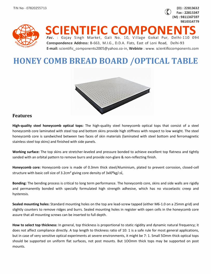
HONEY COMB BREAD BOARD /OPTICAL TABLE
Features
High-quality steel honeycomb optical tops: The high-quality steel honeycomb optical tops that consist of a steel
honeycomb core laminated with steel top and bottom skins provide high stiffness with respect to low weight. The steel
honeycomb core is sandwiched between two faces of skin materials (laminated with steel bottom and ferromagnetic
stainless steel top skins) and finished with side panels.
Working surface: The top skins are stretcher-leveled and pressure bonded to achieve excellent top flatness and tightly
sanded with an orbital pattern to remove burrs and provide non-glare & non-reflecting finish.
Honeycomb core: Honeycomb core is made of 0.3mm thick steel/Aluminium, plated to prevent corrosion, closed-cell
structure with basic cell size of 3.2cm² giving core density of 3xl0⁴kg/㎤,
Bonding: The bending process is critical to long term performance. The honeycomb core, skins and side walls are rigidly
and permanently bonded with specially formulated high strength adhesive, which has no viscoelastic creep and
hysteresis.
Sealed mounting holes: Standard mounting holes on the top are lead-screw tapped (either M6-1.0 on a 25mm grid) and
slightly counters to remove ridges and burrs. Sealed mounting holes in register with open cells in the honeycomb core
assure that all mounting screws can be inserted to full depth.
How to select top thickness: In general, top thickness is proportional to static rigidity and dynamic natural frequency; it
does not affect compliance directly. A top length to thickness ratio of 10: 1 is a safe rule for most general applications,
but in case of very sensitive optical experiments at severe environments, it might be 7: 1. Small 5Omm thick optical tops
should be supported on uniform flat surfaces, not post mounts. But 1OOmm thick tops may be supported on post
mounts.
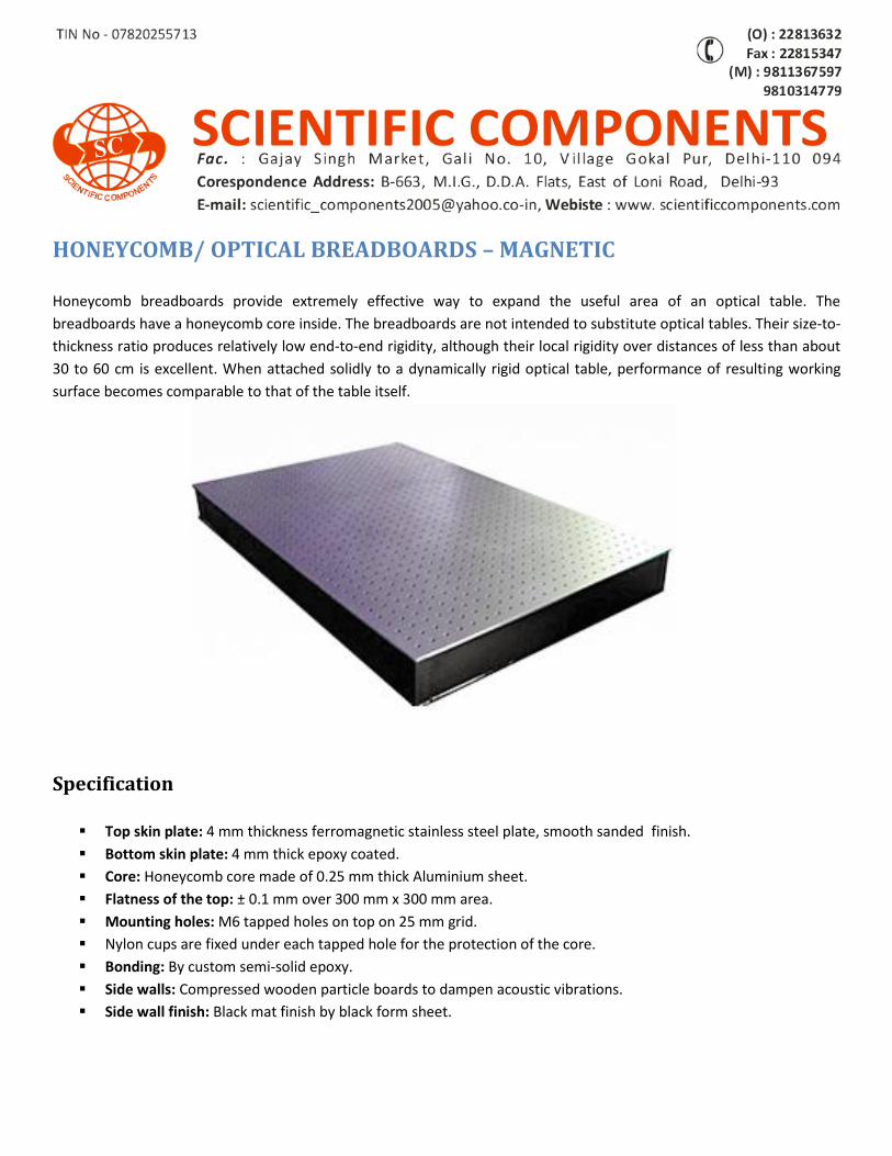
HONEYCOMB/ OPTICAL BREADBOARDS – MAGNETIC Honeycomb breadboards provide extremely effective way to expand the useful area of an optical table. The
breadboards have a honeycomb core inside. The breadboards are not intended to substitute optical tables. Their size-to-
thickness ratio produces relatively low end-to-end rigidity, although their local rigidity over distances of less than about
30 to 60 cm is excellent. When attached solidly to a dynamically rigid optical table, performance of resulting working
surface becomes comparable to that of the table itself.
Specification
Top skin plate: 4 mm thickness ferromagnetic stainless steel plate, smooth sanded finish.
Bottom skin plate: 4 mm thick epoxy coated.
Core: Honeycomb core made of 0.25 mm thick Aluminium sheet.
Flatness of the top: ± 0.1 mm over 300 mm x 300 mm area.
Mounting holes: M6 tapped holes on top on 25 mm grid.
Nylon cups are fixed under each tapped hole for the protection of the core.
Bonding: By custom semi-solid epoxy.
Side walls: Compressed wooden particle boards to dampen acoustic vibrations.
Side wall finish: Black mat finish by black form sheet.
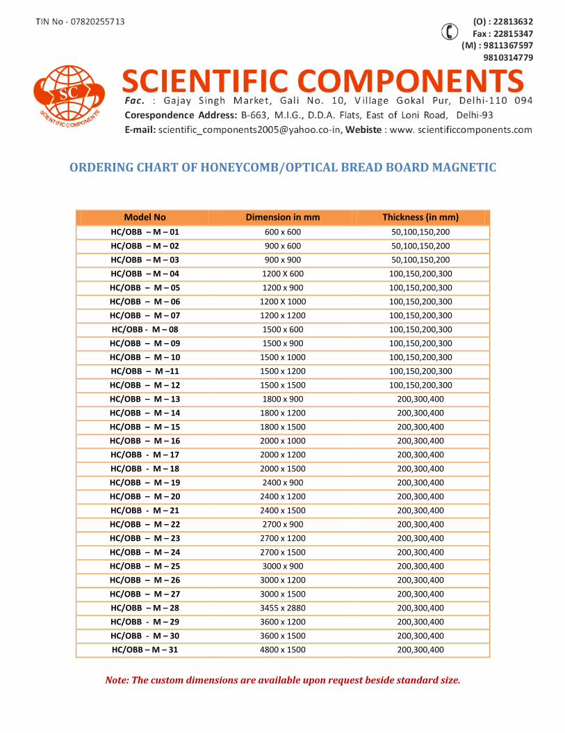
ORDERING CHART OF HONEYCOMB/OPTICAL BREAD BOARD MAGNETIC
Note: The custom dimensions are available upon request beside standard size.
Model No Dimension in mm Thickness (in mm)
HC/OBB – M – 01 600 x 600 50,100,150,200
HC/OBB – M – 02 900 x 600 50,100,150,200
HC/OBB – M – 03 900 x 900 50,100,150,200
HC/OBB – M – 04 1200 X 600 100,150,200,300
HC/OBB – M – 05 1200 x 900 100,150,200,300
HC/OBB – M – 06 1200 X 1000 100,150,200,300
HC/OBB – M – 07 1200 x 1200 100,150,200,300
HC/OBB - M – 08 1500 x 600 100,150,200,300
HC/OBB – M – 09 1500 x 900 100,150,200,300
HC/OBB – M – 10 1500 x 1000 100,150,200,300
HC/OBB – M –11 1500 x 1200 100,150,200,300
HC/OBB – M – 12 1500 x 1500 100,150,200,300
HC/OBB – M – 13 1800 x 900 200,300,400
HC/OBB – M – 14 1800 x 1200 200,300,400
HC/OBB – M – 15 1800 x 1500 200,300,400
HC/OBB – M – 16 2000 x 1000 200,300,400
HC/OBB - M – 17 2000 x 1200 200,300,400
HC/OBB - M – 18 2000 x 1500 200,300,400
HC/OBB – M – 19 2400 x 900 200,300,400
HC/OBB – M – 20 2400 x 1200 200,300,400
HC/OBB - M – 21 2400 x 1500 200,300,400
HC/OBB – M – 22 2700 x 900 200,300,400
HC/OBB – M – 23 2700 x 1200 200,300,400
HC/OBB – M – 24 2700 x 1500 200,300,400
HC/OBB – M – 25 3000 x 900 200,300,400
HC/OBB – M – 26 3000 x 1200 200,300,400
HC/OBB – M – 27 3000 x 1500 200,300,400
HC/OBB – M – 28 3455 x 2880 200,300,400
HC/OBB - M – 29 3600 x 1200 200,300,400
HC/OBB - M – 30 3600 x 1500 200,300,400
HC/OBB – M – 31 4800 x 1500 200,300,400
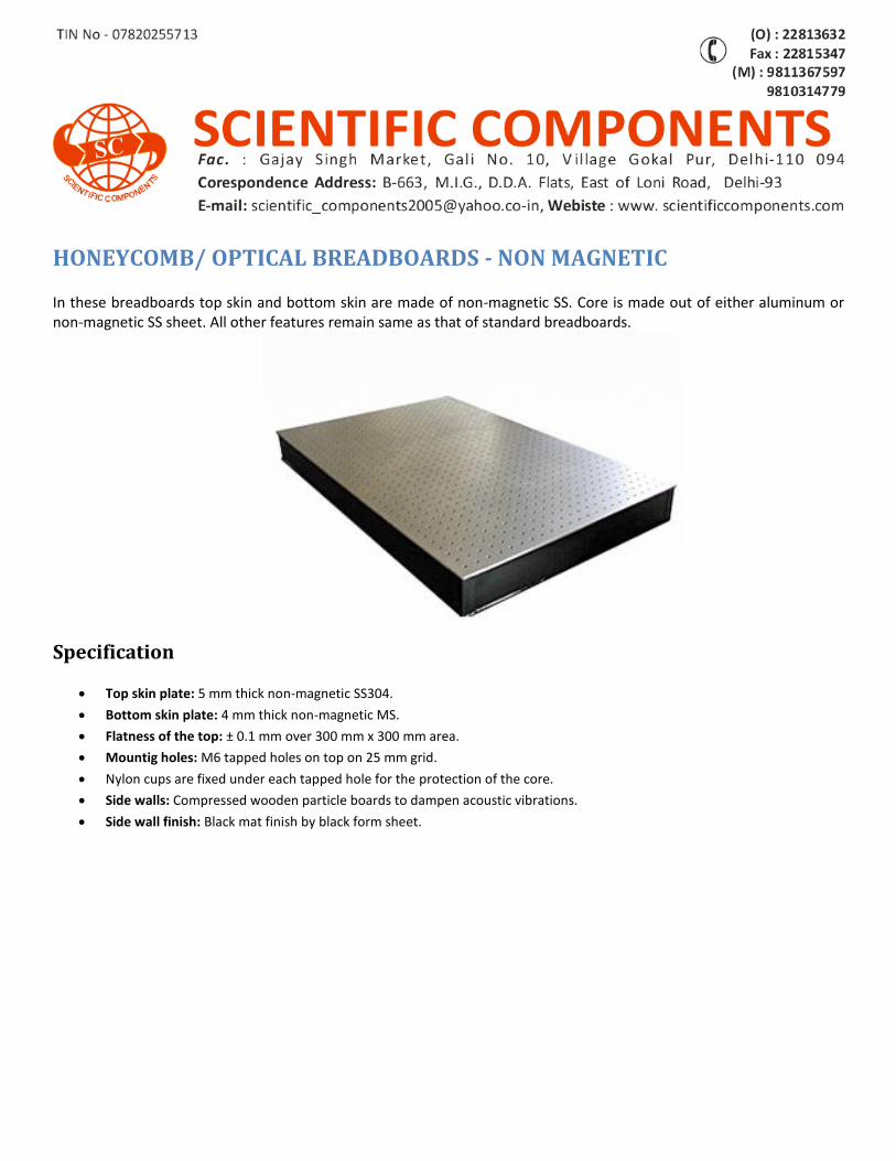
HONEYCOMB/ OPTICAL BREADBOARDS - NON MAGNETIC In these breadboards top skin and bottom skin are made of non-magnetic SS. Core is made out of either aluminum or non-magnetic SS sheet. All other features remain same as that of standard breadboards.
Specification
Top skin plate: 5 mm thick non-magnetic SS304.
Bottom skin plate: 4 mm thick non-magnetic MS.
Flatness of the top: ± 0.1 mm over 300 mm x 300 mm area.
Mountig holes: M6 tapped holes on top on 25 mm grid.
Nylon cups are fixed under each tapped hole for the protection of the core.
Side walls: Compressed wooden particle boards to dampen acoustic vibrations.
Side wall finish: Black mat finish by black form sheet.
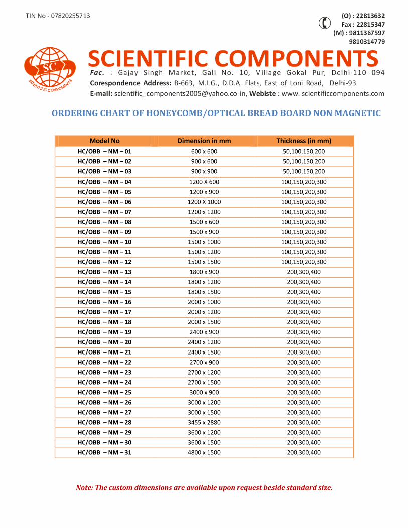
ORDERING CHART OF HONEYCOMB/OPTICAL BREAD BOARD NON MAGNETIC
Note: The custom dimensions are available upon request beside standard size.
Model No Dimension in mm Thickness (in mm)
HC/OBB – NM – 01 600 x 600 50,100,150,200
HC/OBB – NM – 02 900 x 600 50,100,150,200
HC/OBB – NM – 03 900 x 900 50,100,150,200
HC/OBB – NM – 04 1200 X 600 100,150,200,300
HC/OBB – NM – 05 1200 x 900 100,150,200,300
HC/OBB – NM – 06 1200 X 1000 100,150,200,300
HC/OBB – NM – 07 1200 x 1200 100,150,200,300
HC/OBB – NM – 08 1500 x 600 100,150,200,300
HC/OBB – NM – 09 1500 x 900 100,150,200,300
HC/OBB – NM – 10 1500 x 1000 100,150,200,300
HC/OBB – NM – 11 1500 x 1200 100,150,200,300
HC/OBB – NM – 12 1500 x 1500 100,150,200,300
HC/OBB – NM – 13 1800 x 900 200,300,400
HC/OBB – NM – 14 1800 x 1200 200,300,400
HC/OBB – NM – 15 1800 x 1500 200,300,400
HC/OBB – NM – 16 2000 x 1000 200,300,400
HC/OBB – NM – 17 2000 x 1200 200,300,400
HC/OBB – NM – 18 2000 x 1500 200,300,400
HC/OBB – NM – 19 2400 x 900 200,300,400
HC/OBB – NM – 20 2400 x 1200 200,300,400
HC/OBB – NM – 21 2400 x 1500 200,300,400
HC/OBB – NM – 22 2700 x 900 200,300,400
HC/OBB – NM – 23 2700 x 1200 200,300,400
HC/OBB – NM – 24 2700 x 1500 200,300,400
HC/OBB – NM – 25 3000 x 900 200,300,400
HC/OBB – NM – 26 3000 x 1200 200,300,400
HC/OBB – NM – 27 3000 x 1500 200,300,400
HC/OBB – NM – 28 3455 x 2880 200,300,400
HC/OBB – NM – 29 3600 x 1200 200,300,400
HC/OBB – NM – 30 3600 x 1500 200,300,400
HC/OBB – NM – 31 4800 x 1500 200,300,400
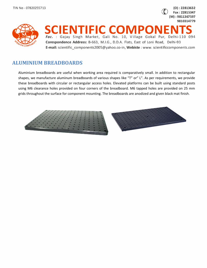
ALUMINIUM BREADBOARDS Aluminium breadboards are useful when working area required is comparatively small. In addition to rectangular
shapes, we manufacture aluminum breadboards of various shapes like “T” or” L”. As per requirements, we provide
these breadboards with circular or rectangular access holes. Elevated platforms can be built using standard posts
using M6 clearance holes provided on four corners of the breadboard. M6 tapped holes are provided on 25 mm
grids throughout the surface for component mounting. The breadboards are anodized and given black mat finish.
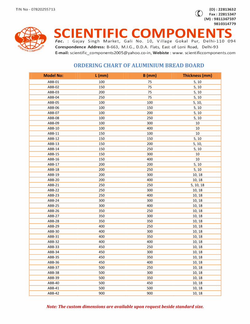
ORDERING CHART OF ALUMINIUM BREAD BOARD
Note: The custom dimensions are available upon request beside standard size.
Model No: L (mm) B (mm) Thickness (mm)
ABB-01 100 75 5, 10
ABB-02 150 75 5, 10
ABB-03 200 75 5, 10
ABB-04 250 75 5, 10
ABB-05 100 100 5, 10,
ABB-06 100 150 5, 10
ABB-07 100 200 5, 10
ABB-08 100 250 5, 10
ABB-09 100 300 10
ABB-10 100 400 10
ABB-11 150 100 10
ABB-12 150 150 5, 10
ABB-13 150 200 5, 10,
ABB-14 150 250 5, 10
ABB-15 150 300 10
ABB-16 150 400 10
ABB-17 200 200 5, 10
ABB-18 200 250 5, 10
ABB-19 200 300 10, 18
ABB-20 200 400 10, 18
ABB-21 250 250 5, 10, 18
ABB-22 250 300 10, 18
ABB-23 250 400 10, 18
ABB-24 300 300 10, 18
ABB-25 300 400 10, 18
ABB-26 350 250 10, 18
ABB-27 350 300 10, 18
ABB-28 350 350 10, 18
ABB-29 400 250 10, 18
ABB-30 400 300 10, 18
ABB-31 400 350 10, 18
ABB-32 400 400 10, 18
ABB-33 450 250 10, 18
ABB-34 450 300 10, 18
ABB-35 450 350 10, 18
ABB-36 450 400 10, 18
ABB-37 500 250 10, 18
ABB-38 500 300 10, 18
ABB-39 500 350 10, 18
ABB-40 500 450 10, 18
ABB-41 500 500 10, 18
ABB-42 900 900 10, 18
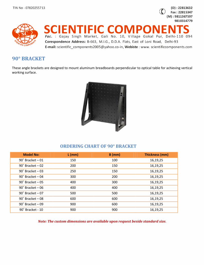
90° BRACKET
These angle brackets are designed to mount aluminum breadboards perpendicular to optical table for achieving vertical working surface.
ORDERING CHART OF 90° BRACKET
Note: The custom dimensions are available upon request beside standard size.
Model No: L (mm) B (mm) Thickness (mm)
90˚ Bracket – 01 150 100 16,19,25
90˚ Bracket – 02 200 150 16,19,25
90˚ Bracket – 03 250 150 16,19,25
90˚ Bracket – 04 300 200 16,19,25
90˚ Bracket – 05 400 300 16,19,25
90˚ Bracket – 06 400 400 16,19,25
90˚ Bracket – 07 500 500 16,19,25
90˚ Bracket – 08 600 600 16,19,25
90˚ Bracket – 09 900 600 16,19,25
90˚ Bracket - 10 900 900 16,19,25
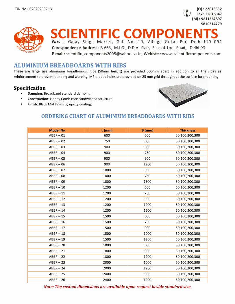
ALUMINIUM BREADBOARDS WITH RIBS These are large size aluminum breadboards. Ribs (50mm height) are provided 300mm apart in addition to all the sides as
reinforcement to prevent bending and warping. M6 tapped holes are provided on 25 mm grid throughout the surface for mounting.
Specification Damping: Broadband standard damping.
Construction: Honey Comb core sandwiched structure.
Finish: Black Mat finish by epoxy coating.
ORDERING CHART OF ALUMINIUM BREADBOARDS WITH RIBS
Note: The custom dimensions are available upon request beside standard size.
Model No L (mm) B (mm) Thickness
ABBR – 01 600 600 50,100,200,300
ABBR – 02 750 600 50,100,200,300
ABBR – 03 900 600 50,100,200,300
ABBR – 04 900 750 50,100,200,300
ABBR – 05 900 900 50,100,200,300
ABBR – 06 900 1200 50,100,200,300
ABBR – 07 1000 500 50,100,200,300
ABBR – 08 1000 750 50,100,200,300
ABBR – 09 1000 1500 50,100,200,300
ABBR – 10 1200 600 50,100,200,300
ABBR – 11 1200 750 50,100,200,300
ABBR – 12 1200 900 50,100,200,300
ABBR – 13 1200 1200 50,100,200,300
ABBR – 14 1200 1500 50,100,200,300
ABBR – 15 1500 600 50,100,200,300
ABBR – 16 1500 750 50,100,200,300
ABBR – 17 1500 900 50,100,200,300
ABBR – 18 1500 1000 50,100,200,300
ABBR – 19 1500 1200 50,100,200,300
ABBR – 20 1800 600 50,100,200,300
ABBR – 21 1800 900 50,100,200,300
ABBR – 22 1800 1200 50,100,200,300
ABBR – 23 2000 1000 50,100,200,300
ABBR – 24 2000 1200 50,100,200,300
ABBR – 25 2400 900 50,100,200,300
ABBR – 26 2400 1200 50,100,200,300
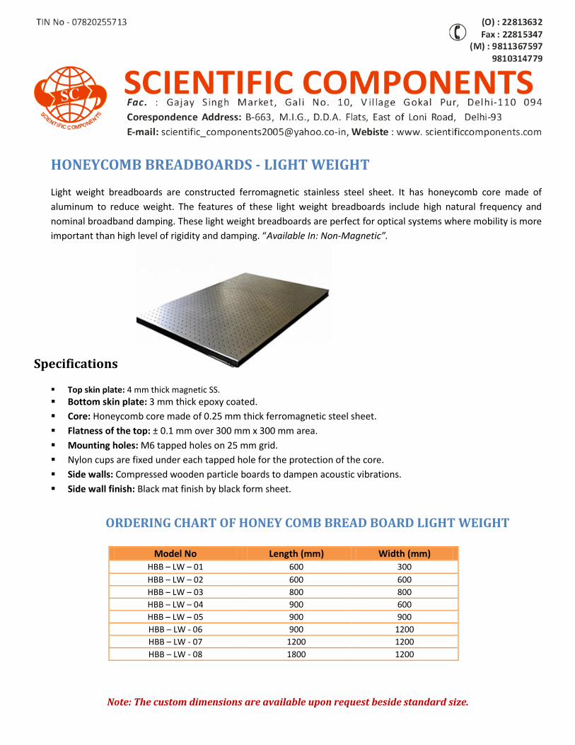
HONEYCOMB BREADBOARDS - LIGHT WEIGHT Light weight breadboards are constructed ferromagnetic stainless steel sheet. It has honeycomb core made of
aluminum to reduce weight. The features of these light weight breadboards include high natural frequency and
nominal broadband damping. These light weight breadboards are perfect for optical systems where mobility is more
important than high level of rigidity and damping. “Available In: Non-Magnetic”.
Specifications
Top skin plate: 4 mm thick magnetic SS.
Bottom skin plate: 3 mm thick epoxy coated.
Core: Honeycomb core made of 0.25 mm thick ferromagnetic steel sheet.
Flatness of the top: ± 0.1 mm over 300 mm x 300 mm area.
Mounting holes: M6 tapped holes on 25 mm grid.
Nylon cups are fixed under each tapped hole for the protection of the core.
Side walls: Compressed wooden particle boards to dampen acoustic vibrations.
Side wall finish: Black mat finish by black form sheet.
ORDERING CHART OF HONEY COMB BREAD BOARD LIGHT WEIGHT
Model No Length (mm) Width (mm) HBB – LW – 01 600 300
HBB – LW – 02 600 600
HBB – LW – 03 800 800
HBB – LW – 04 900 600
HBB – LW – 05 900 900
HBB – LW - 06 900 1200
HBB – LW - 07 1200 1200
HBB – LW - 08 1800 1200
Note: The custom dimensions are available upon request beside standard size.
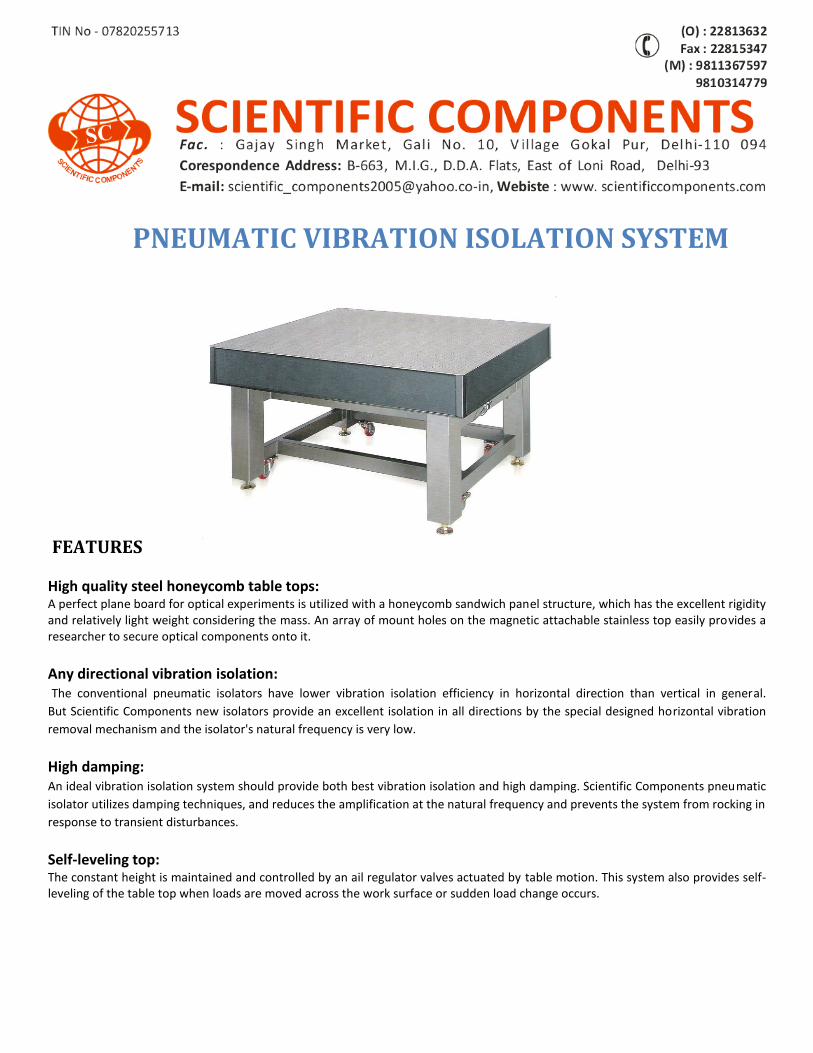
PNEUMATIC VIBRATION ISOLATION SYSTEM
FEATURES
High quality steel honeycomb table tops: A perfect plane board for optical experiments is utilized with a honeycomb sandwich panel structure, which has the excellent rigidity and relatively light weight considering the mass. An array of mount holes on the magnetic attachable stainless top easily provides a researcher to secure optical components onto it.
Any directional vibration isolation: The conventional pneumatic isolators have lower vibration isolation efficiency in horizontal direction than vertical in general.
But Scientific Components new isolators provide an excellent isolation in all directions by the special designed horizontal vibration
removal mechanism and the isolator's natural frequency is very low.
High damping: An ideal vibration isolation system should provide both best vibration isolation and high damping. Scientific Components pneumatic
isolator utilizes damping techniques, and reduces the amplification at the natural frequency and prevents the system from rocking in
response to transient disturbances.
Self-leveling top: The constant height is maintained and controlled by an ail regulator valves actuated by table motion. This system also provides self-leveling of the table top when loads are moved across the work surface or sudden load change occurs.
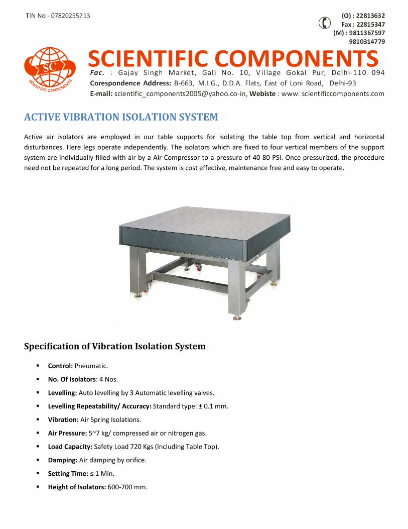
ACTIVE VIBRATION ISOLATION SYSTEM
Active air isolators are employed in our table supports for isolating the table top from vertical and horizontal
disturbances. Here legs operate independently. The isolators which are fixed to four vertical members of the support
system are individually filled with air by a Air Compressor to a pressure of 40-80 PSI. Once pressurized, the procedure
need not be repeated for a long period. The system is cost effective, maintenance free and easy to operate.
Specification of Vibration Isolation System
Control: Pneumatic.
No. Of Isolators: 4 Nos.
Levelling: Auto levelling by 3 Automatic levelling valves.
Levelling Repeatability/ Accuracy: Standard type: ± 0.1 mm.
Vibration: Air Spring Isolations.
Air Pressure: 5~7 kg/ compressed air or nitrogen gas.
Load Capacity: Safety Load 720 Kgs (Including Table Top).
Damping: Air damping by orifice.
Setting Time: ≤ 1 Min.
Height of Isolators: 600-700 mm.
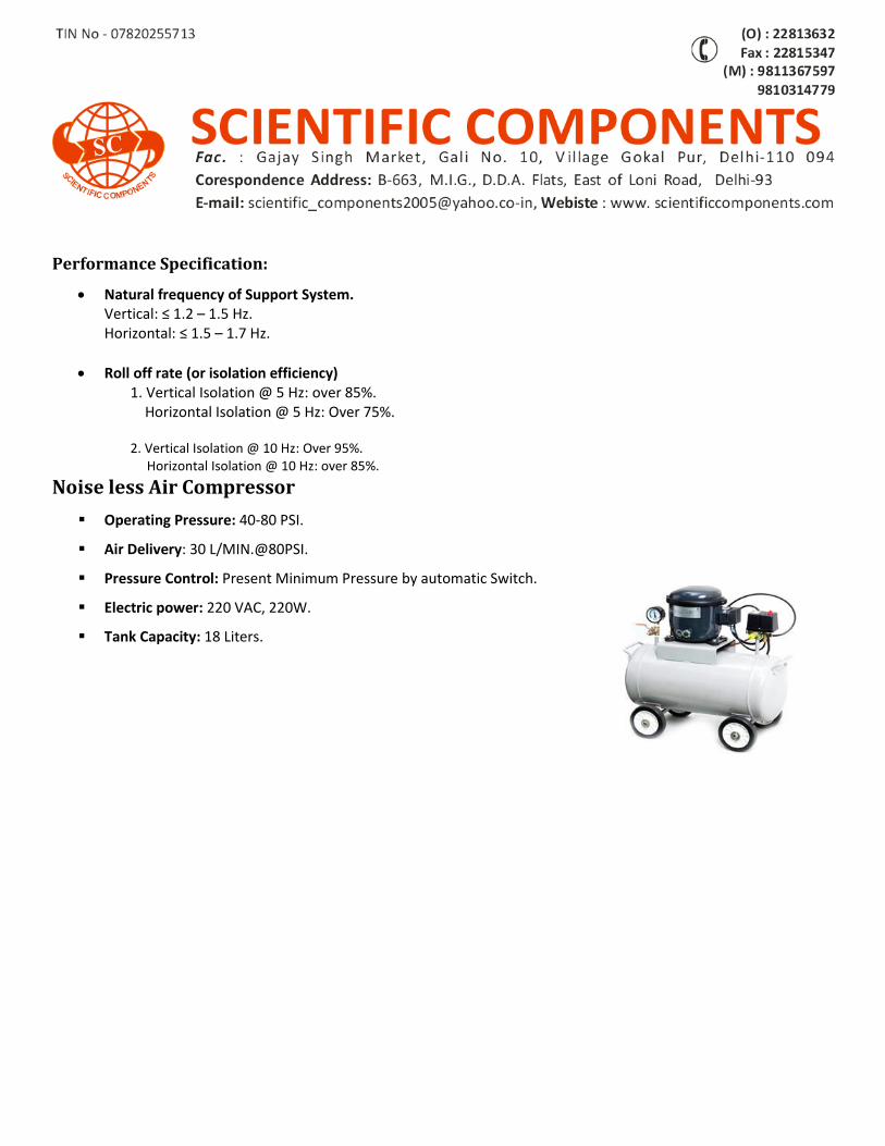
Performance Specification:
Natural frequency of Support System. Vertical: ≤ 1.2 – 1.5 Hz. Horizontal: ≤ 1.5 – 1.7 Hz.
Roll off rate (or isolation efficiency) 1. Vertical Isolation @ 5 Hz: over 85%. Horizontal Isolation @ 5 Hz: Over 75%. 2. Vertical Isolation @ 10 Hz: Over 95%. Horizontal Isolation @ 10 Hz: over 85%.
Noise less Air Compressor
Operating Pressure: 40-80 PSI.
Air Delivery: 30 L/MIN.@80PSI.
Pressure Control: Present Minimum Pressure by automatic Switch.
Electric power: 220 VAC, 220W.
Tank Capacity: 18 Liters.
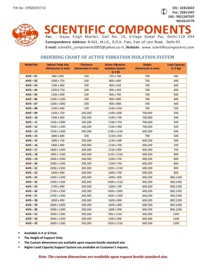
ORDERING CHART OF ACTIVE VIBRATION ISOLATION SYSTEM
Available in 4 or 6-Post.
The Height of Support Only.
The Custom dimensions are available upon request beside standard size.
Higher Load Capacity Support System are available on Customer’s request.
Note: The custom dimensions are available upon request beside standard size.
Model No: Optical Table Size (Dimension in mm)
Thickness (Dimension in mm)
Active Vibration Isolation System
(L X B)
Height (Dimension in mm)
Load Capacity (± 2 Kg)
AVIS – 01 900 x 900 100 750 x 700 700 400
AVIS – 02 1000 x 750 100 800 x 600 700 400
AVIS – 03 1200 x 600 100 900 x 450 700 400
AVIS – 04 1200 X 750 100 900 x 450 700 400
AVIS – 05 1200 x 900 100 900 x 700 700 400
AVIS – 06 1200 x 1200 100 900 x 900 700 400
AVIS – 07 1200 x 1000 100 900 x 800 700 400
AVIS – 08 1500 x 600 100 1100 x 450 700 500
AVIS – 09 1500 x 750 100,200 1100 x 600 700,600 500
AVIS – 10 1500 x 900 100,200 1100 x 700 700,600 500
AVIS – 11 1500 x 1000 100,200 1100 x 750 700,600 500
AVIS – 12 1500 x 1200 100,200 1100 x 900 700,600 500
AVIS – 13 1500 x 1500 200,300 1100 x 1150 600,500 500
AVIS – 14 1800 x 600 100 1150 x 450 700 500
AVIS – 15 1800 x 750 200,300 1150 x 600 600,500 500
AVIS – 16 1800 x 900 200,300 1150 x 700 600,500 500
AVIS – 17 1800 x 1200 200,300 1150 x 900 600,500 750
AVIS – 18 1800 x 1500 200,300 1150 x 1150 600,500 800
AVIS – 19 2000 x 1000 200,300 1200 x 750 600,500 800
AVIS – 20 2000 x 1200 200,300 1200 x 750 600,500 800
AVIS – 21 2000 x 1500 200,300 1200 x 1150 600,500 800
AVIS – 22 2400 x 900 200,300 1400 x 700 600,500 800
AVIS – 23 2400 x 1200 200,300 1400 x 900 600,500 800,1200
AVIS – 24 2400 x 1500 200,300 1400 x 1150 600,500 800,1200
AVIS – 25 2700 x 900 200,300 1400 x 700 600,500 800,1200
AVIS – 26 2700 x 1200 200,300 1400 x 1000 600,500 800,1200
AVIS – 27 2700 x 1500 200,300 1400 x 1300 600,500 800,1200
AVIS – 28 3000 x 900 200,300 1600 x 800 600,500 800,1200
AVIS – 29 3000 x 1000 200,300 1600 x 900 600,500 800,1200
AVIS – 30 3000 x 1200 200,300 1600 x 900 600,500 800,1200
AVIS – 31 3000 x 1500 200,300 900 x 1150 600,500 1200
AVIS – 32 3600 x 1200 200,300 1050 x 900 600,500 1200
AVIS – 33 3600 x 1500 200,300 1050 x 1150 600,500 1200
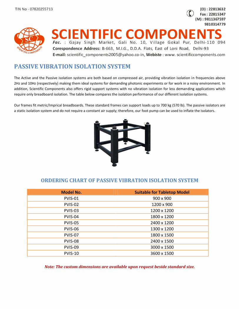
PASSIVE VIBRATION ISOLATION SYSTEM
The Active and the Passive isolation systems are both based on compressed air, providing vibration isolation in frequencies above
2Hz and 10Hz (respectively) making them ideal systems for demanding photonic experiments or for work in a noisy environment. In
addition, Scientific Components also offers rigid support systems with no vibration isolation for less demanding applications which
require only breadboard isolation. The table below compares the isolation performance of our different isolation systems.
Our frames fit metric/Imprical breadboards. These standard frames can support loads up to 700 kg (570 lb). The passive isolators are
a static isolation system and do not require a constant air supply; therefore, our foot pump can be used to inflate the isolators.
ORDERING CHART OF PASSIVE VIBRATION ISOLATION SYSTEM
Model No. Suitable for Tabletop Model PVIS-01 900 x 900
PVIS-02 1200 x 900
PVIS-03 1200 x 1200
PVIS-04 1800 x 1200
PVIS-05 2400 x 1200
PVIS-06 1300 x 1200
PVIS-07 1800 x 1500
PVIS-08 2400 x 1500
PVIS-09 3000 x 1500
PVIS-10 3600 x 1500
Note: The custom dimensions are available upon request beside standard size.
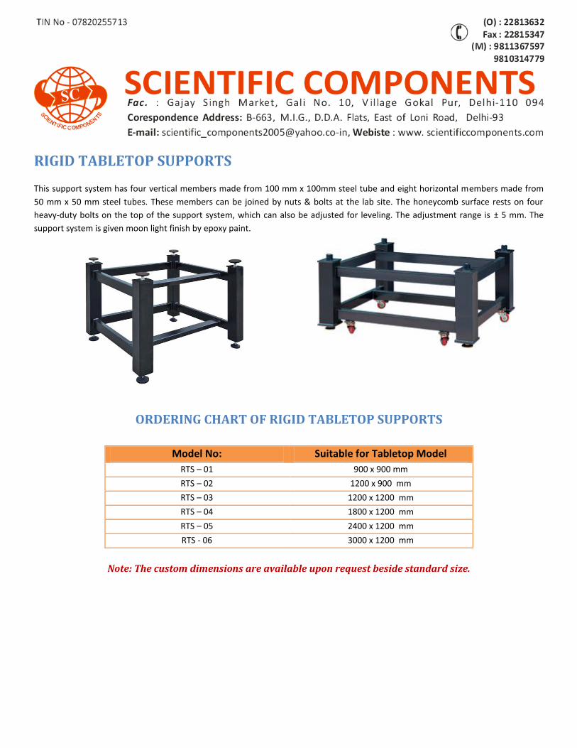
RIGID TABLETOP SUPPORTS
This support system has four vertical members made from 100 mm x 100mm steel tube and eight horizontal members made from
50 mm x 50 mm steel tubes. These members can be joined by nuts & bolts at the lab site. The honeycomb surface rests on four
heavy-duty bolts on the top of the support system, which can also be adjusted for leveling. The adjustment range is ± 5 mm. The
support system is given moon light finish by epoxy paint.
ORDERING CHART OF RIGID TABLETOP SUPPORTS
Note: The custom dimensions are available upon request beside standard size.
Model No: Suitable for Tabletop Model
RTS – 01 900 x 900 mm
RTS – 02 1200 x 900 mm
RTS – 03 1200 x 1200 mm
RTS – 04 1800 x 1200 mm
RTS – 05 2400 x 1200 mm
RTS - 06 3000 x 1200 mm
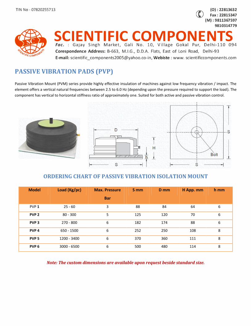
PASSIVE VIBRATION PADS (PVP) Passive Vibration Mount (PVM) series provide highly effective insulation of machines against low frequency vibration / impact. The
element offers a vertical natural frequencies between 2.5 to 6.0 Hz (depending upon the pressure required to support the load). The
component has vertical to horizontal stiffness ratio of approximately one. Suited for both active and passive vibration control.
ORDERING CHART OF PASSIVE VIBRATION ISOLATION MOUNT
Note: The custom dimensions are available upon request beside standard size.
Model Load (Kg/pc) Max. Pressure
Bar
S mm D mm H App. mm h mm
PVP 1 25 - 60 3 88 84 64 6
PVP 2 80 - 300 5 125 120 70 6
PVP 3 270 - 800 6 182 174 88 6
PVP 4 650 - 1500 6 252 250 108 8
PVP 5 1200 - 3400 6 370 360 111 8
PVP 6 3000 - 6500 6 500 480 114 8
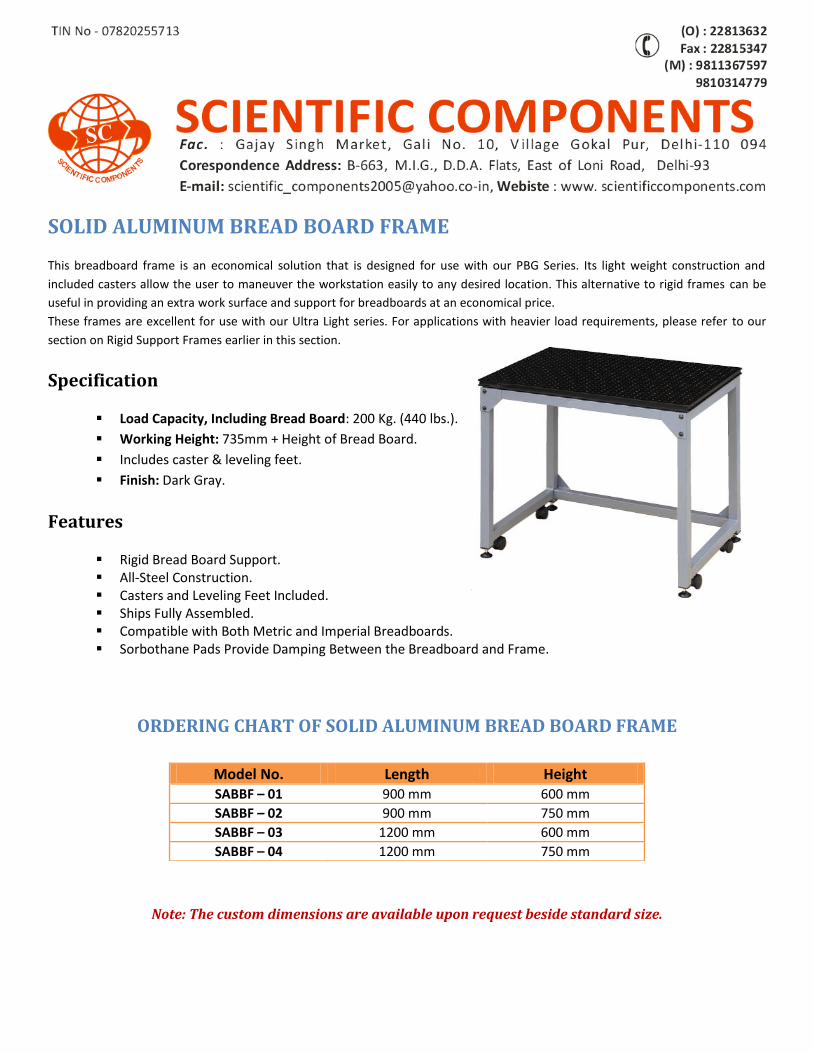
SOLID ALUMINUM BREAD BOARD FRAME
This breadboard frame is an economical solution that is designed for use with our PBG Series. Its light weight construction and
included casters allow the user to maneuver the workstation easily to any desired location. This alternative to rigid frames can be
useful in providing an extra work surface and support for breadboards at an economical price.
These frames are excellent for use with our Ultra Light series. For applications with heavier load requirements, please refer to our
section on Rigid Support Frames earlier in this section.
Specification
Load Capacity, Including Bread Board: 200 Kg. (440 lbs.).
Working Height: 735mm + Height of Bread Board.
Includes caster & leveling feet.
Finish: Dark Gray.
Features
Rigid Bread Board Support. All-Steel Construction. Casters and Leveling Feet Included. Ships Fully Assembled. Compatible with Both Metric and Imperial Breadboards. Sorbothane Pads Provide Damping Between the Breadboard and Frame.
ORDERING CHART OF SOLID ALUMINUM BREAD BOARD FRAME
Note: The custom dimensions are available upon request beside standard size.
Model No. Length Height SABBF – 01 900 mm 600 mm
SABBF – 02 900 mm 750 mm
SABBF – 03 1200 mm 600 mm
SABBF – 04 1200 mm 750 mm
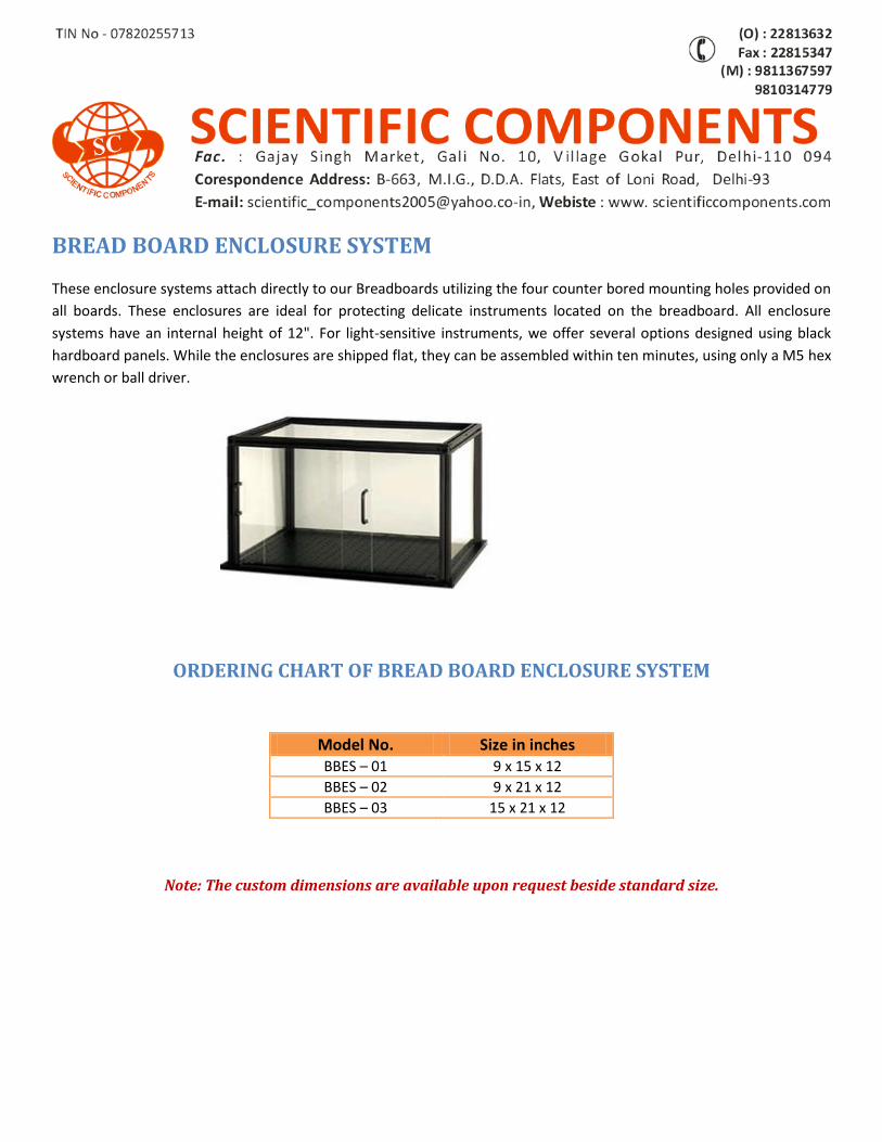
BREAD BOARD ENCLOSURE SYSTEM
These enclosure systems attach directly to our Breadboards utilizing the four counter bored mounting holes provided on
all boards. These enclosures are ideal for protecting delicate instruments located on the breadboard. All enclosure
systems have an internal height of 12". For light-sensitive instruments, we offer several options designed using black
hardboard panels. While the enclosures are shipped flat, they can be assembled within ten minutes, using only a M5 hex
wrench or ball driver.
ORDERING CHART OF BREAD BOARD ENCLOSURE SYSTEM
Note: The custom dimensions are available upon request beside standard size.
Model No. Size in inches BBES – 01 9 x 15 x 12
BBES – 02 9 x 21 x 12
BBES – 03 15 x 21 x 12
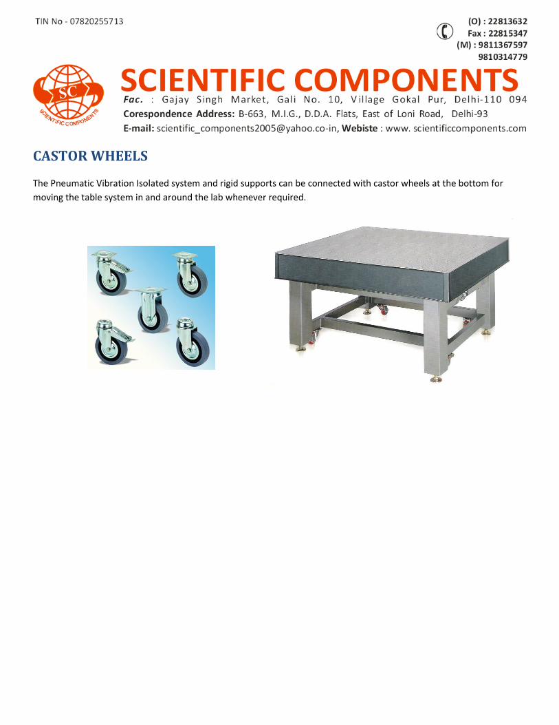
CASTOR WHEELS
The Pneumatic Vibration Isolated system and rigid supports can be connected with castor wheels at the bottom for
moving the table system in and around the lab whenever required.
OPTO-MECHANICS
M/s Scientific Components manufacture wide range of products in the field of Opto-Mechanics & Optical Instruments etc.
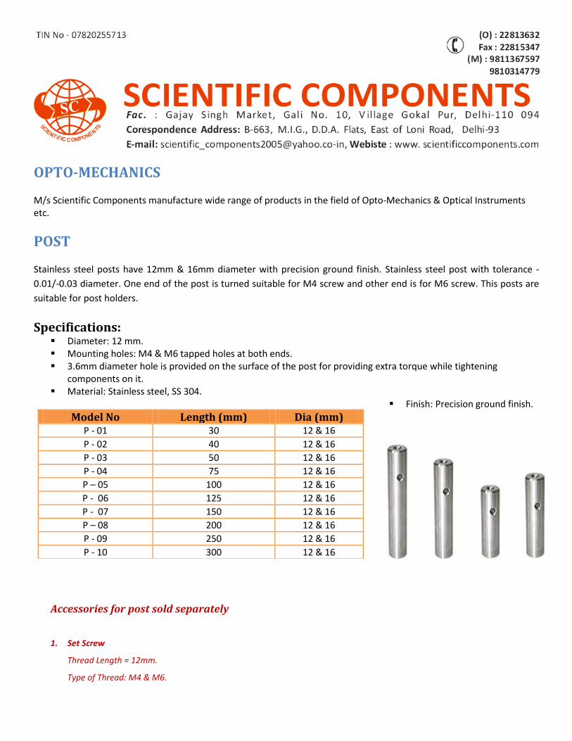
POST
Stainless steel posts have 12mm & 16mm diameter with precision ground finish. Stainless steel post with tolerance -
0.01/-0.03 diameter. One end of the post is turned suitable for M4 screw and other end is for M6 screw. This posts are
suitable for post holders.
Specifications: Diameter: 12 mm. Mounting holes: M4 & M6 tapped holes at both ends. 3.6mm diameter hole is provided on the surface of the post for providing extra torque while tightening
components on it. Material: Stainless steel, SS 304.
Finish: Precision ground finish.
Accessories for post sold separately
1. Set Screw
Thread Length = 12mm.
Type of Thread: M4 & M6.
Model No Length (mm) Dia (mm) P - 01 30 12 & 16
P - 02 40 12 & 16
P - 03 50 12 & 16
P - 04 75 12 & 16
P – 05 100 12 & 16
P - 06 125 12 & 16
P - 07 150 12 & 16
P – 08 200 12 & 16
P - 09 250 12 & 16
P - 10 300 12 & 16
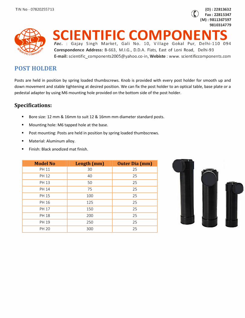
POST HOLDER
Posts are held in position by spring loaded thumbscrews. Knob is provided with every post holder for smooth up and
down movement and stable tightening at desired position. We can fix the post holder to an optical table, base plate or a
pedestal adapter by using M6 mounting hole provided on the bottom side of the post holder.
Specifications:
Bore size: 12 mm & 16mm to suit 12 & 16mm mm diameter standard posts.
Mounting hole: M6 tapped hole at the base.
Post mounting: Posts are held in position by spring loaded thumbscrews.
Material: Aluminum alloy.
Finish: Black anodized mat finish.
Model No Length (mm) Outer Dia (mm) PH 11 30 25
PH 12 40 25
PH 13 50 25
PH 14 75 25
PH 15 100 25
PH 16 125 25
PH 17 150 25
PH 18 200 25
PH 19 250 25
PH 20 300 25
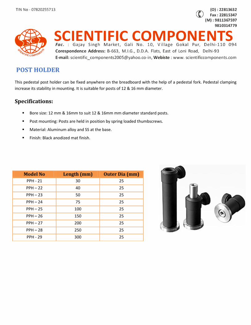
POST HOLDER
This pedestal post holder can be fixed anywhere on the breadboard with the help of a pedestal fork. Pedestal clamping
increase its stability in mounting. It is suitable for posts of 12 & 16 mm diameter.
Specifications:
Bore size: 12 mm & 16mm to suit 12 & 16mm mm diameter standard posts.
Post mounting: Posts are held in position by spring loaded thumbscrews.
Material: Aluminum alloy and SS at the base.
Finish: Black anodized mat finish.
Model No Length (mm) Outer Dia (mm)
PPH - 21 30 25
PPH – 22 40 25
PPH – 23 50 25
PPH – 24 75 25
PPH – 25 100 25
PPH – 26 150 25
PPH – 27 200 25
PPH – 28 250 25
PPH - 29 300 25
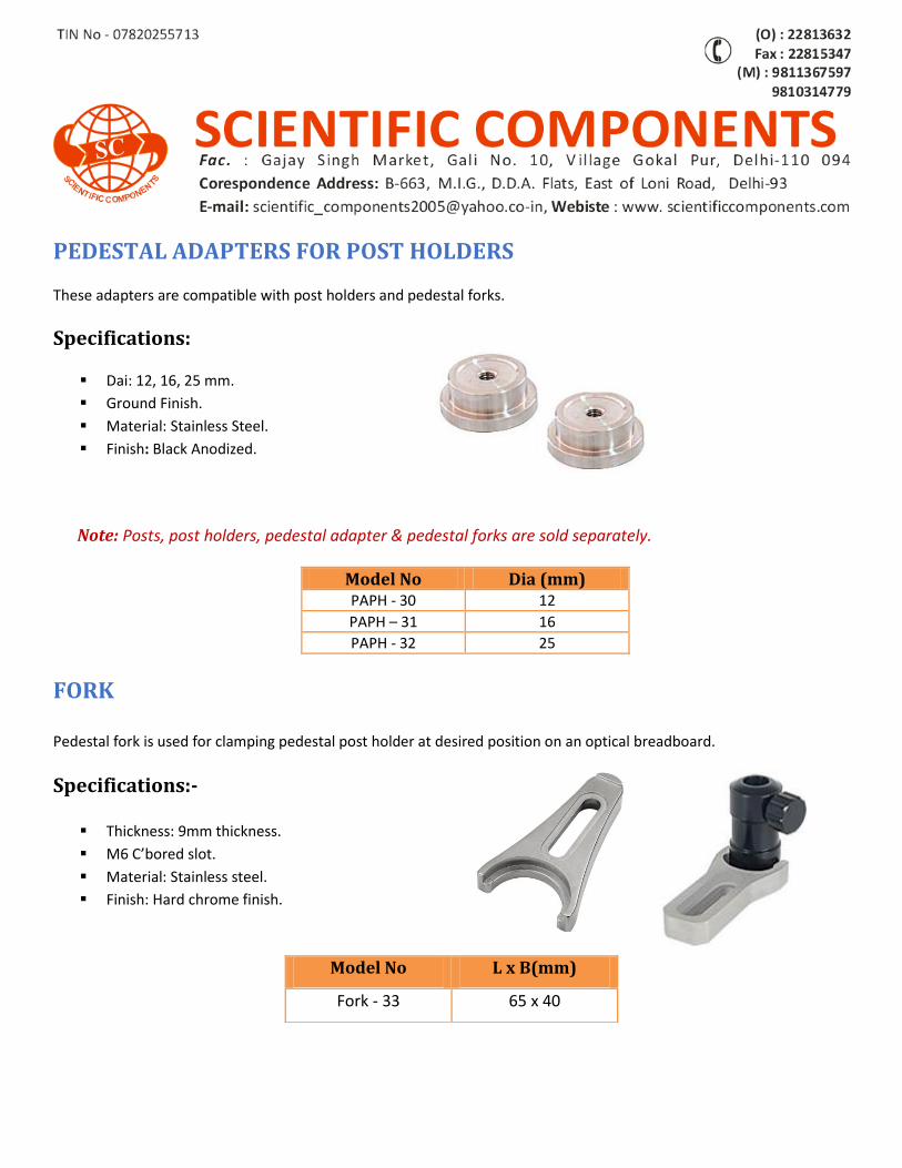
PEDESTAL ADAPTERS FOR POST HOLDERS
These adapters are compatible with post holders and pedestal forks.
Specifications:
Dai: 12, 16, 25 mm.
Ground Finish.
Material: Stainless Steel.
Finish: Black Anodized.
Note: Posts, post holders, pedestal adapter & pedestal forks are sold separately.
Model No Dia (mm) PAPH - 30 12
PAPH – 31 16
PAPH - 32 25
FORK Pedestal fork is used for clamping pedestal post holder at desired position on an optical breadboard.
Specifications:-
Thickness: 9mm thickness.
M6 C’bored slot.
Material: Stainless steel.
Finish: Hard chrome finish.
Model No L x B(mm)
Fork - 33 65 x 40
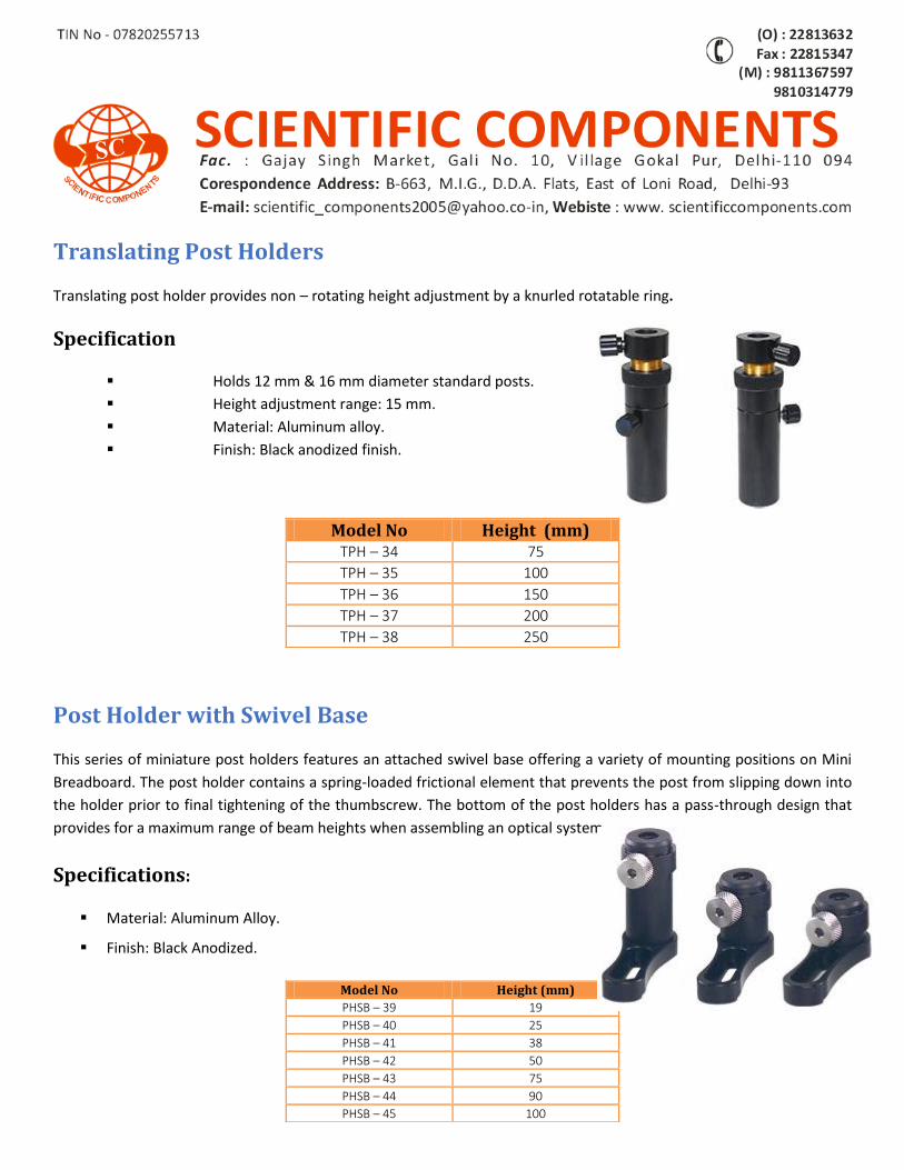
Translating Post Holders
Translating post holder provides non – rotating height adjustment by a knurled rotatable ring.
Specification
Holds 12 mm & 16 mm diameter standard posts.
Height adjustment range: 15 mm.
Material: Aluminum alloy.
Finish: Black anodized finish.
Post Holder with Swivel Base
This series of miniature post holders features an attached swivel base offering a variety of mounting positions on Mini
Breadboard. The post holder contains a spring-loaded frictional element that prevents the post from slipping down into
the holder prior to final tightening of the thumbscrew. The bottom of the post holders has a pass-through design that
provides for a maximum range of beam heights when assembling an optical system.
Specifications:
Material: Aluminum Alloy.
Finish: Black Anodized.
Model No Height (mm) TPH – 34 75
TPH – 35 100
TPH – 36 150
TPH – 37 200
TPH – 38 250
Model No Height (mm)
PHSB – 39 19
PHSB – 40 25
PHSB – 41 38
PHSB – 42 50
PHSB – 43 75
PHSB – 44 90
PHSB – 45 100
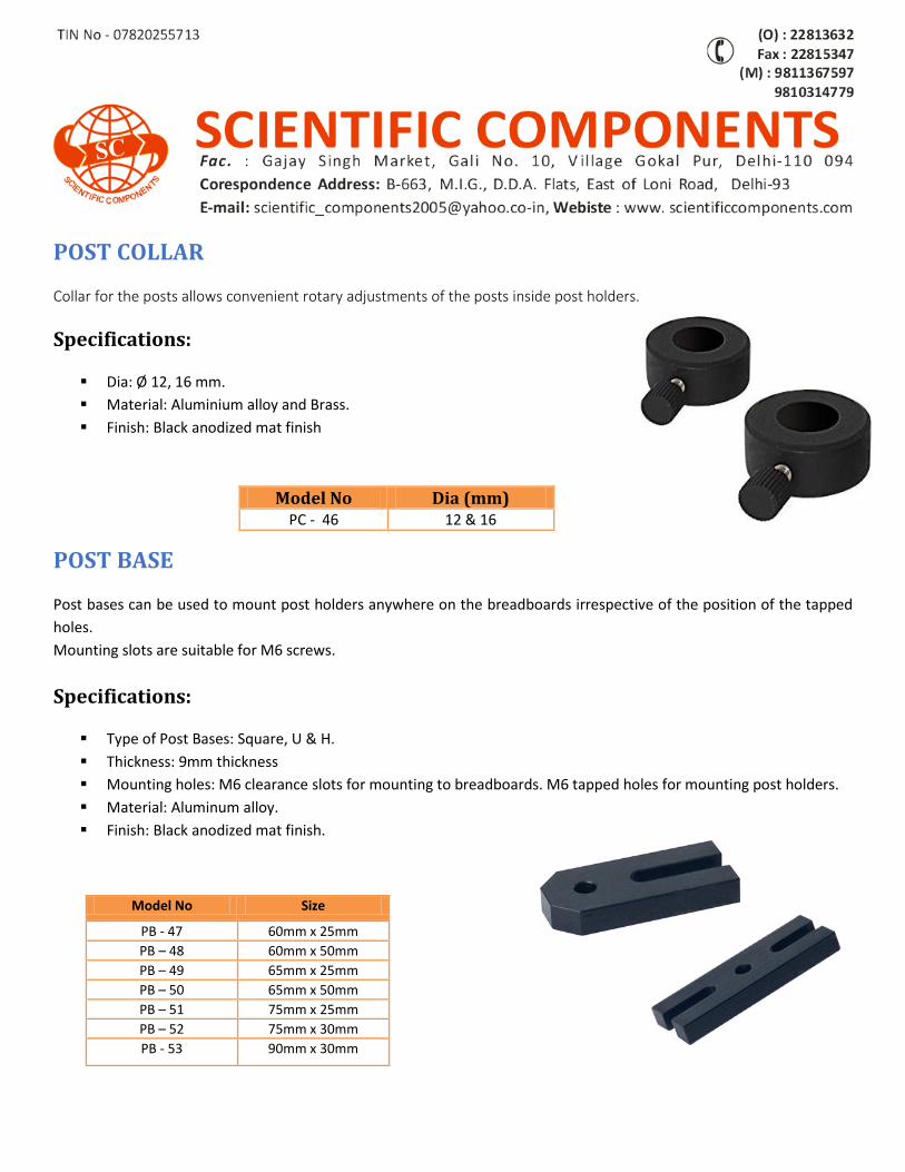
POST COLLAR
Collar for the posts allows convenient rotary adjustments of the posts inside post holders.
Specifications:
Dia: Ø 12, 16 mm.
Material: Aluminium alloy and Brass.
Finish: Black anodized mat finish
POST BASE
Post bases can be used to mount post holders anywhere on the breadboards irrespective of the position of the tapped
holes.
Mounting slots are suitable for M6 screws.
Specifications:
Type of Post Bases: Square, U & H.
Thickness: 9mm thickness
Mounting holes: M6 clearance slots for mounting to breadboards. M6 tapped holes for mounting post holders.
Material: Aluminum alloy.
Finish: Black anodized mat finish.
Model No Dia (mm) PC - 46 12 & 16
Model No Size
PB - 47 60mm x 25mm
PB – 48 60mm x 50mm
PB – 49 65mm x 25mm
PB – 50 65mm x 50mm
PB – 51 75mm x 25mm
PB – 52 75mm x 30mm
PB - 53 90mm x 30mm
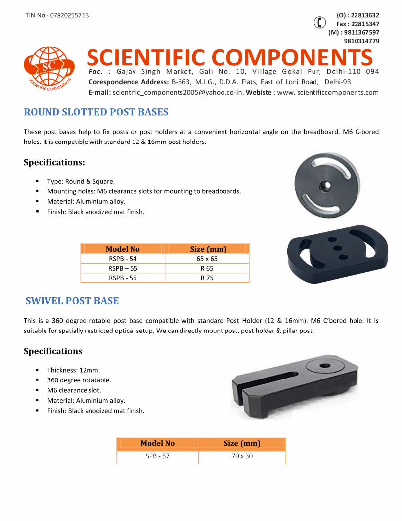
ROUND SLOTTED POST BASES
These post bases help to fix posts or post holders at a convenient horizontal angle on the breadboard. M6 C-bored
holes. It is compatible with standard 12 & 16mm post holders.
Specifications:
Type: Round & Square.
Mounting holes: M6 clearance slots for mounting to breadboards.
Material: Aluminium alloy.
Finish: Black anodized mat finish.
SWIVEL POST BASE
This is a 360 degree rotable post base compatible with standard Post Holder (12 & 16mm). M6 C’bored hole. It is
suitable for spatially restricted optical setup. We can directly mount post, post holder & pillar post.
Specifications
Thickness: 12mm.
360 degree rotatable.
M6 clearance slot.
Material: Aluminium alloy.
Finish: Black anodized mat finish.
Model No Size (mm) RSPB - 54 65 x 65
RSPB – 55 R 65
RSPB - 56 R 75
Model No Size (mm)
SPB - 57 70 x 30
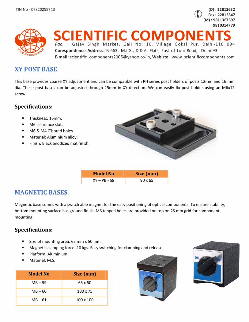
XY POST BASE
This base provides coarse XY adjustment and can be compatible with PH series post holders of posts 12mm and 16 mm
dia. These post bases can be adjusted through 25mm in XY direction. We can easily fix post holder using an M6x12
screw.
Specifications:
Thickness: 16mm.
M6 clearance slot.
M6 & M4 C’bored holes.
Material: Aluminium alloy.
Finish: Black anodized mat finish.
MAGNETIC BASES
Magnetic base comes with a switch able magnet for the easy positioning of optical components. To ensure stability,
bottom mounting surface has ground finish. M6 tapped holes are provided on top on 25 mm grid for component
mounting.
Specifications:
Size of mounting area: 65 mm x 50 mm.
Magnetic clamping force: 10 kgs. Easy switching for clamping and release.
Platform: Aluminium.
Material: M.S.
Model No Size (mm)
XY – PB - 58 90 x 65
Model No Size (mm)
MB – 59 65 x 50
MB – 60 100 x 75
MB – 61 100 x 100
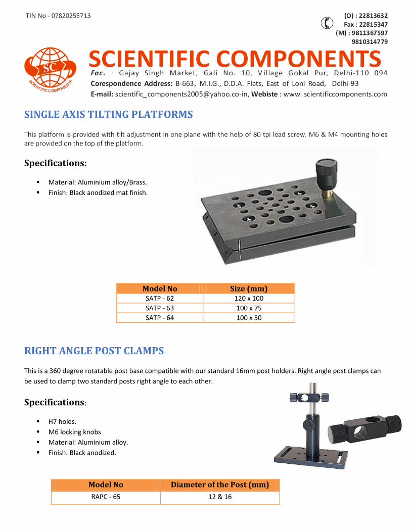
SINGLE AXIS TILTING PLATFORMS
This platform is provided with tilt adjustment in one plane with the help of 80 tpi lead screw. M6 & M4 mounting holes are provided on the top of the platform.
Specifications:
Material: Aluminium alloy/Brass.
Finish: Black anodized mat finish.
RIGHT ANGLE POST CLAMPS
This is a 360 degree rotatable post base compatible with our standard 16mm post holders. Right angle post clamps can
be used to clamp two standard posts right angle to each other.
Specifications:
H7 holes.
M6 locking knobs
Material: Aluminium alloy.
Finish: Black anodized.
Model No Size (mm) SATP - 62 120 x 100
SATP - 63 100 x 75
SATP - 64 100 x 50
Model No Diameter of the Post (mm)
RAPC - 65 12 & 16
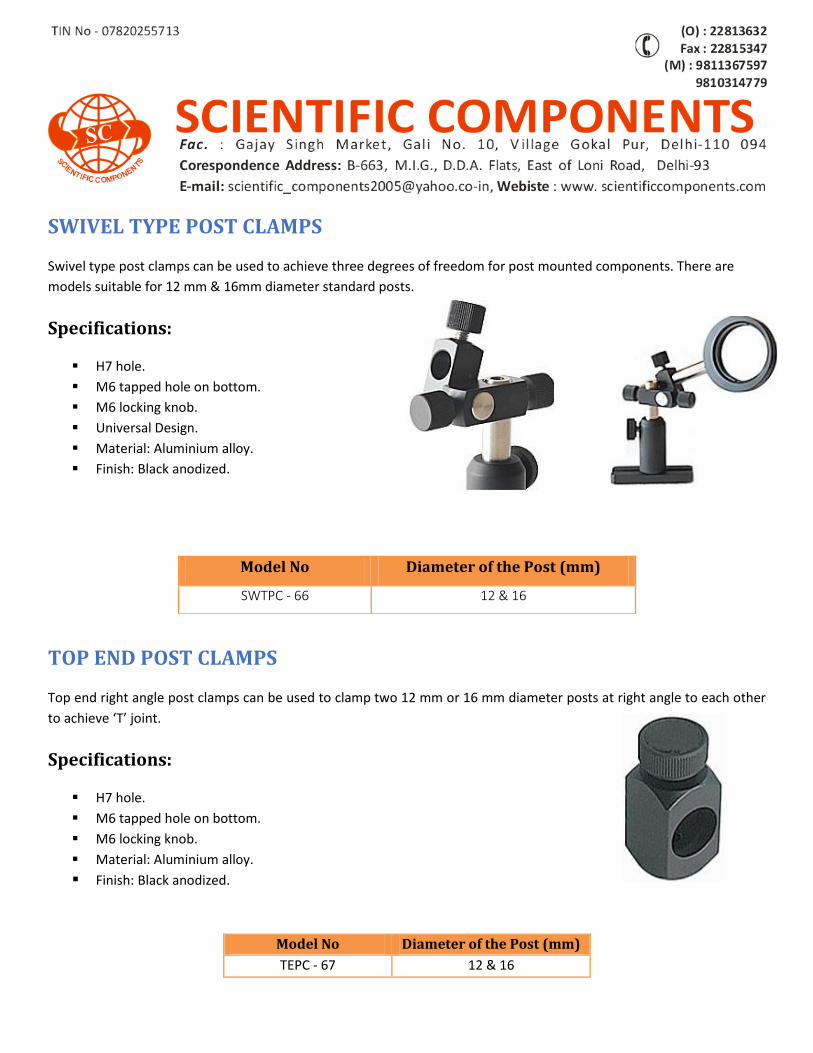
SWIVEL TYPE POST CLAMPS
Swivel type post clamps can be used to achieve three degrees of freedom for post mounted components. There are
models suitable for 12 mm & 16mm diameter standard posts.
Specifications:
H7 hole.
M6 tapped hole on bottom.
M6 locking knob.
Universal Design.
Material: Aluminium alloy.
Finish: Black anodized.
TOP END POST CLAMPS
Top end right angle post clamps can be used to clamp two 12 mm or 16 mm diameter posts at right angle to each other
to achieve ‘T’ joint.
Specifications:
H7 hole.
M6 tapped hole on bottom.
M6 locking knob.
Material: Aluminium alloy.
Finish: Black anodized.
Model No Diameter of the Post (mm)
SWTPC - 66 12 & 16
Model No Diameter of the Post (mm)
TEPC - 67 12 & 16
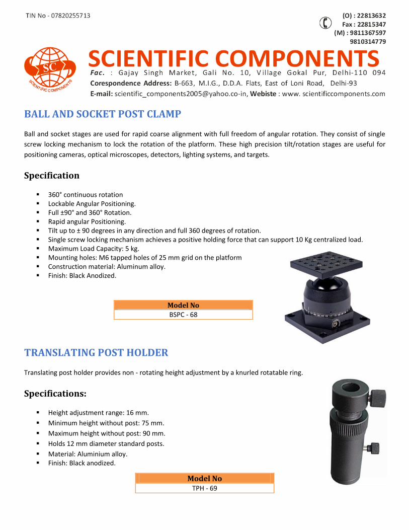
BALL AND SOCKET POST CLAMP
Ball and socket stages are used for rapid coarse alignment with full freedom of angular rotation. They consist of single
screw locking mechanism to lock the rotation of the platform. These high precision tilt/rotation stages are useful for
positioning cameras, optical microscopes, detectors, lighting systems, and targets.
Specification
360° continuous rotation Lockable Angular Positioning. Full ±90° and 360° Rotation. Rapid angular Positioning. Tilt up to ± 90 degrees in any direction and full 360 degrees of rotation. Single screw locking mechanism achieves a positive holding force that can support 10 Kg centralized load. Maximum Load Capacity: 5 kg. Mounting holes: M6 tapped holes of 25 mm grid on the platform Construction material: Aluminum alloy. Finish: Black Anodized.
TRANSLATING POST HOLDER
Translating post holder provides non - rotating height adjustment by a knurled rotatable ring.
Specifications:
Height adjustment range: 16 mm.
Minimum height without post: 75 mm.
Maximum height without post: 90 mm.
Holds 12 mm diameter standard posts.
Material: Aluminium alloy. Finish: Black anodized.
Model No BSPC - 68
Model No TPH - 69
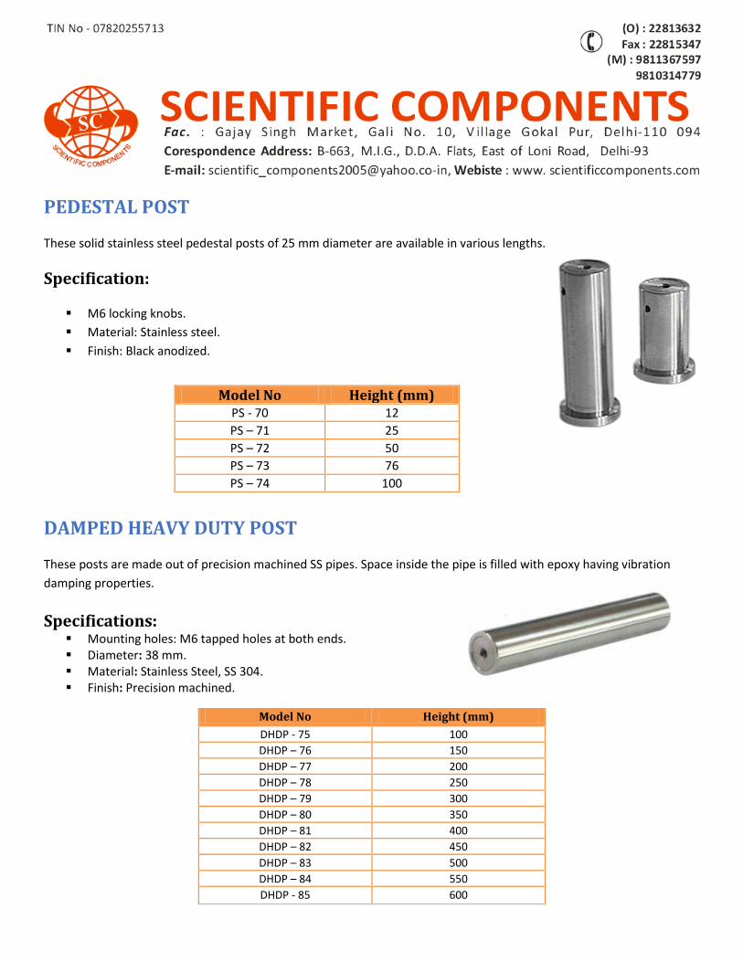
PEDESTAL POST
These solid stainless steel pedestal posts of 25 mm diameter are available in various lengths.
Specification:
M6 locking knobs.
Material: Stainless steel.
Finish: Black anodized.
DAMPED HEAVY DUTY POST
These posts are made out of precision machined SS pipes. Space inside the pipe is filled with epoxy having vibration
damping properties.
Specifications: Mounting holes: M6 tapped holes at both ends. Diameter: 38 mm. Material: Stainless Steel, SS 304. Finish: Precision machined.
Model No Height (mm) PS - 70 12
PS – 71 25
PS – 72 50
PS – 73 76
PS – 74 100
Model No Height (mm)
DHDP - 75 100
DHDP – 76 150
DHDP – 77 200
DHDP – 78 250
DHDP – 79 300
DHDP – 80 350
DHDP – 81 400
DHDP – 82 450
DHDP – 83 500
DHDP – 84 550
DHDP - 85 600
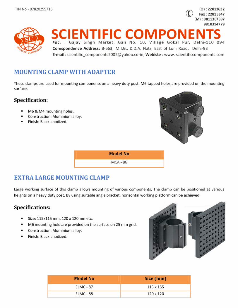
MOUNTING CLAMP WITH ADAPTER
These clamps are used for mounting components on a heavy duty post. M6 tapped holes are provided on the mounting surface.
Specification:
M6 & M4 mounting holes. Construction: Aluminium alloy. Finish: Black anodized.
EXTRA LARGE MOUNTING CLAMP
Large working surface of this clamp allows mounting of various components. The clamp can be positioned at various
heights on a heavy duty post. By using suitable angle bracket, horizontal working platform can be achieved.
Specifications:
Size: 115x115 mm, 120 x 120mm etc.
M6 mounting hole are provided on the surface on 25 mm grid.
Construction: Aluminium alloy.
Finish: Black anodized.
Model No
MCA - 86
Model No Size (mm)
ELMC - 87 115 x 155
ELMC - 88 120 x 120
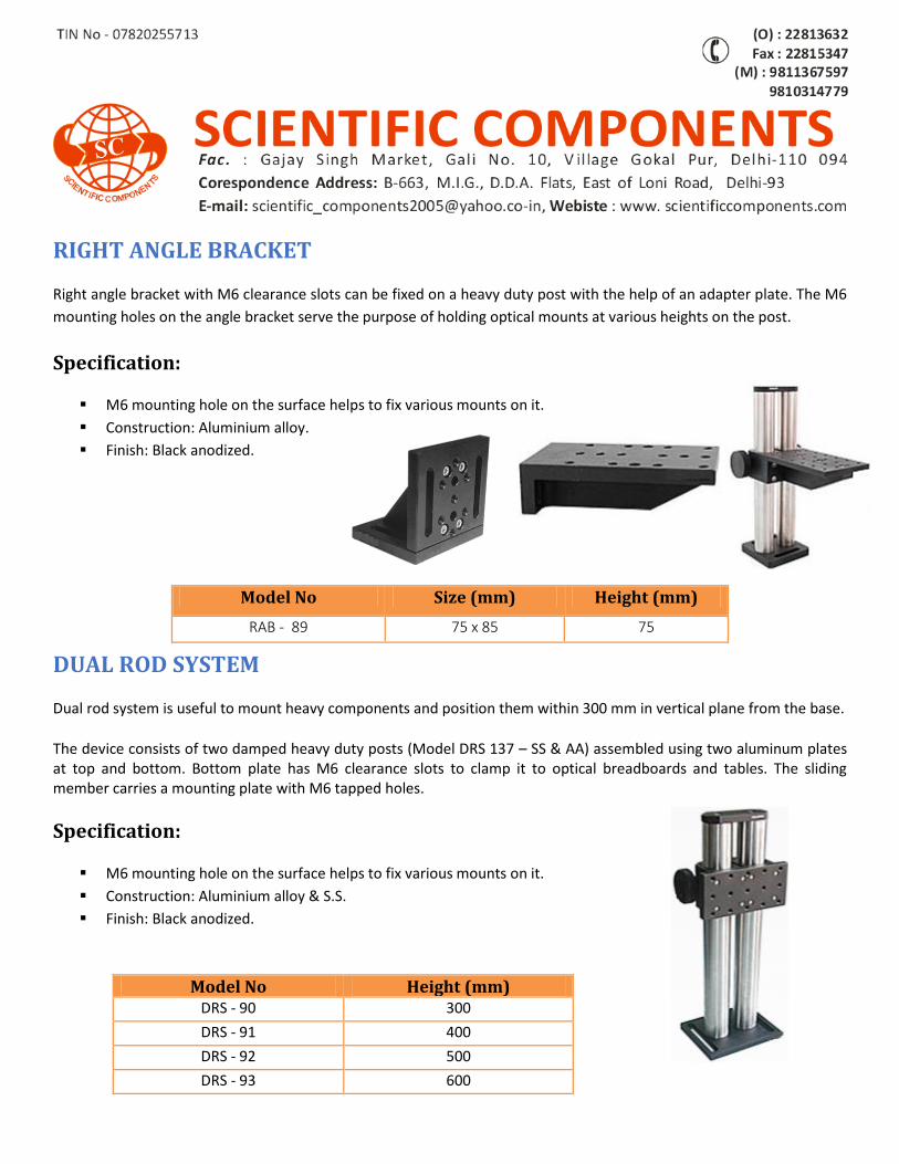
RIGHT ANGLE BRACKET
Right angle bracket with M6 clearance slots can be fixed on a heavy duty post with the help of an adapter plate. The M6
mounting holes on the angle bracket serve the purpose of holding optical mounts at various heights on the post.
Specification:
M6 mounting hole on the surface helps to fix various mounts on it.
Construction: Aluminium alloy.
Finish: Black anodized.
DUAL ROD SYSTEM
Dual rod system is useful to mount heavy components and position them within 300 mm in vertical plane from the base.
The device consists of two damped heavy duty posts (Model DRS 137 – SS & AA) assembled using two aluminum plates at top and bottom. Bottom plate has M6 clearance slots to clamp it to optical breadboards and tables. The sliding member carries a mounting plate with M6 tapped holes.
Specification:
M6 mounting hole on the surface helps to fix various mounts on it.
Construction: Aluminium alloy & S.S.
Finish: Black anodized.
Model No Size (mm) Height (mm)
RAB - 89 75 x 85 75
Model No Height (mm) DRS - 90 300
DRS - 91 400
DRS - 92 500
DRS - 93 600
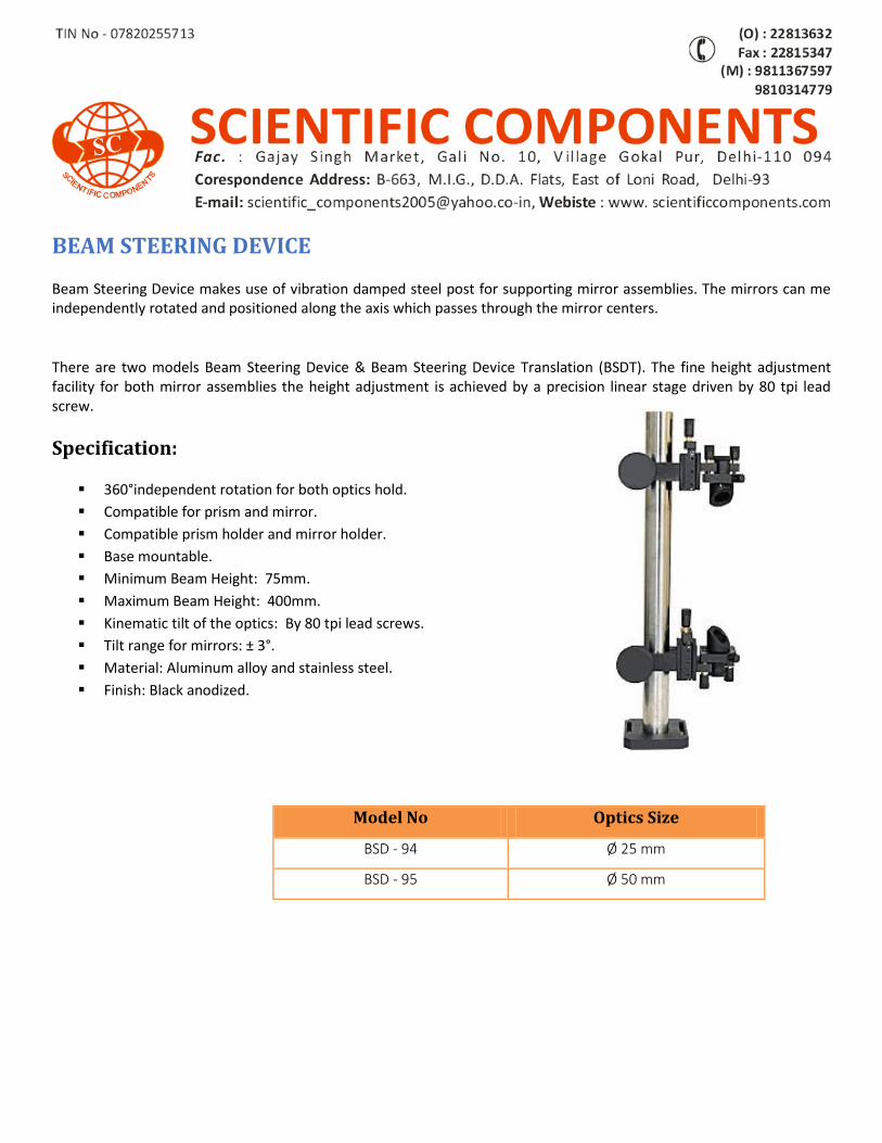
BEAM STEERING DEVICE
Beam Steering Device makes use of vibration damped steel post for supporting mirror assemblies. The mirrors can me independently rotated and positioned along the axis which passes through the mirror centers.
There are two models Beam Steering Device & Beam Steering Device Translation (BSDT). The fine height adjustment facility for both mirror assemblies the height adjustment is achieved by a precision linear stage driven by 80 tpi lead screw.
Specification:
360°independent rotation for both optics hold.
Compatible for prism and mirror.
Compatible prism holder and mirror holder.
Base mountable.
Minimum Beam Height: 75mm.
Maximum Beam Height: 400mm.
Kinematic tilt of the optics: By 80 tpi lead screws.
Tilt range for mirrors: ± 3°.
Material: Aluminum alloy and stainless steel.
Finish: Black anodized.
Model No Optics Size
BSD - 94 Ø 25 mm
BSD - 95 Ø 50 mm
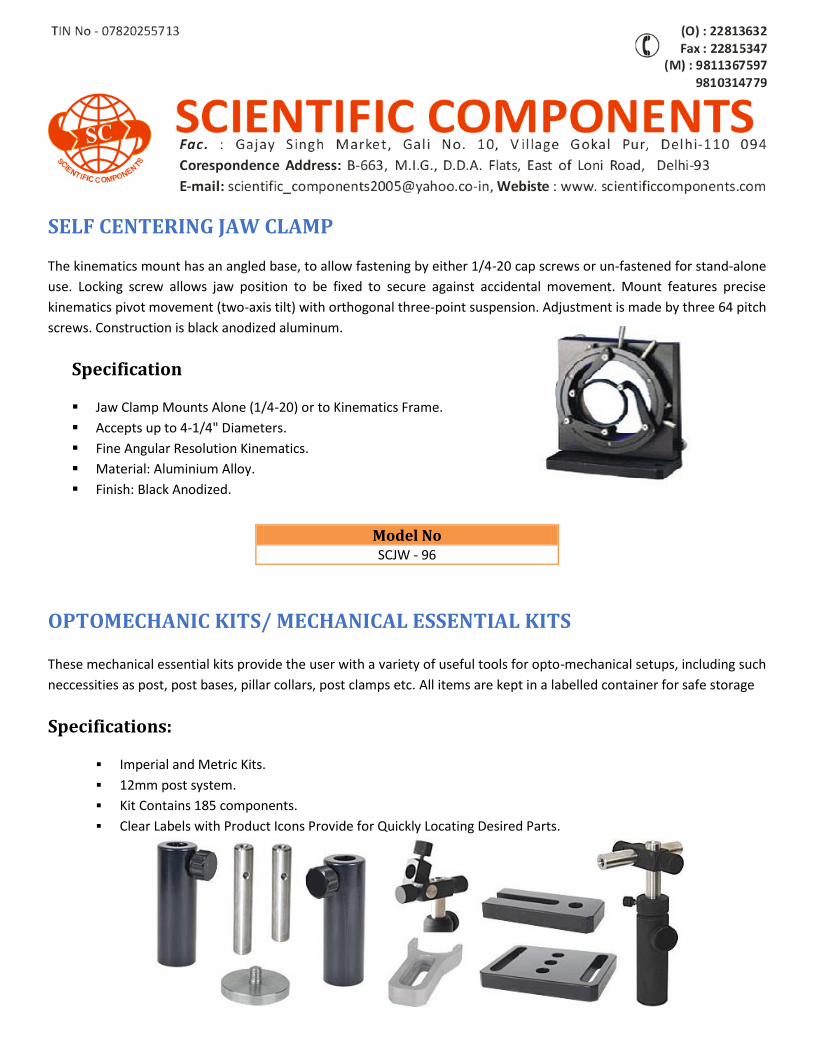
SELF CENTERING JAW CLAMP
The kinematics mount has an angled base, to allow fastening by either 1/4-20 cap screws or un-fastened for stand-alone
use. Locking screw allows jaw position to be fixed to secure against accidental movement. Mount features precise
kinematics pivot movement (two-axis tilt) with orthogonal three-point suspension. Adjustment is made by three 64 pitch
screws. Construction is black anodized aluminum.
Specification
Jaw Clamp Mounts Alone (1/4-20) or to Kinematics Frame.
Accepts up to 4-1/4" Diameters.
Fine Angular Resolution Kinematics.
Material: Aluminium Alloy.
Finish: Black Anodized.
OPTOMECHANIC KITS/ MECHANICAL ESSENTIAL KITS
These mechanical essential kits provide the user with a variety of useful tools for opto-mechanical setups, including such
neccessities as post, post bases, pillar collars, post clamps etc. All items are kept in a labelled container for safe storage
Specifications:
Imperial and Metric Kits.
12mm post system.
Kit Contains 185 components.
Clear Labels with Product Icons Provide for Quickly Locating Desired Parts.
Model No
SCJW - 96
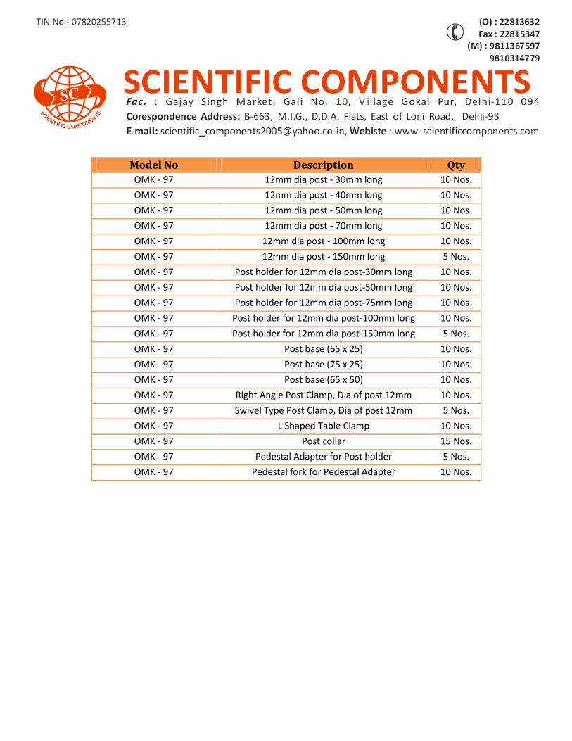
Model No Description Qty OMK - 97 12mm dia post - 30mm long 10 Nos.
OMK - 97 12mm dia post - 40mm long 10 Nos.
OMK - 97 12mm dia post - 50mm long 10 Nos.
OMK - 97 12mm dia post - 70mm long 10 Nos.
OMK - 97 12mm dia post - 100mm long 10 Nos.
OMK - 97 12mm dia post - 150mm long 5 Nos.
OMK - 97 Post holder for 12mm dia post-30mm long 10 Nos.
OMK - 97 Post holder for 12mm dia post-50mm long 10 Nos.
OMK - 97 Post holder for 12mm dia post-75mm long 10 Nos.
OMK - 97 Post holder for 12mm dia post-100mm long 10 Nos.
OMK - 97 Post holder for 12mm dia post-150mm long 5 Nos.
OMK - 97 Post base (65 x 25) 10 Nos.
OMK - 97 Post base (75 x 25) 10 Nos.
OMK - 97 Post base (65 x 50) 10 Nos.
OMK - 97 Right Angle Post Clamp, Dia of post 12mm 10 Nos.
OMK - 97 Swivel Type Post Clamp, Dia of post 12mm 5 Nos.
OMK - 97 L Shaped Table Clamp 10 Nos.
OMK - 97 Post collar 15 Nos.
OMK - 97 Pedestal Adapter for Post holder 5 Nos.
OMK - 97 Pedestal fork for Pedestal Adapter 10 Nos.
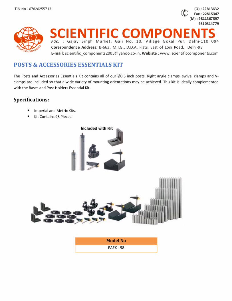
POSTS & ACCESSORIES ESSENTIALS KIT
The Posts and Accessories Essentials Kit contains all of our Ø0.5 inch posts. Right angle clamps, swivel clamps and V-
clamps are included so that a wide variety of mounting orientations may be achieved. This kit is ideally complemented
with the Bases and Post Holders Essential Kit.
Specifications:
Imperial and Metric Kits.
Kit Contains 98 Pieces.
Model No
PAEK - 98
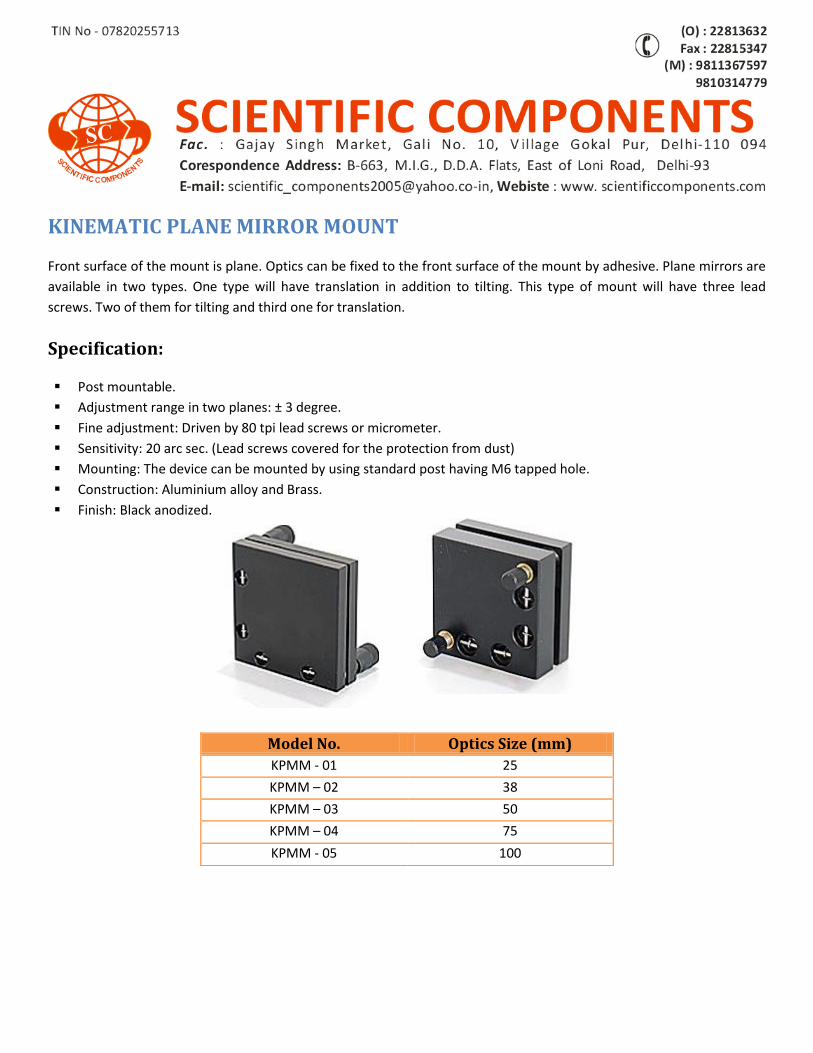
KINEMATIC PLANE MIRROR MOUNT
Front surface of the mount is plane. Optics can be fixed to the front surface of the mount by adhesive. Plane mirrors are
available in two types. One type will have translation in addition to tilting. This type of mount will have three lead
screws. Two of them for tilting and third one for translation.
Specification:
Post mountable.
Adjustment range in two planes: ± 3 degree.
Fine adjustment: Driven by 80 tpi lead screws or micrometer.
Sensitivity: 20 arc sec. (Lead screws covered for the protection from dust)
Mounting: The device can be mounted by using standard post having M6 tapped hole.
Construction: Aluminium alloy and Brass.
Finish: Black anodized.
Model No. Optics Size (mm)
KPMM - 01 25
KPMM – 02 38
KPMM – 03 50
KPMM – 04 75
KPMM - 05 100
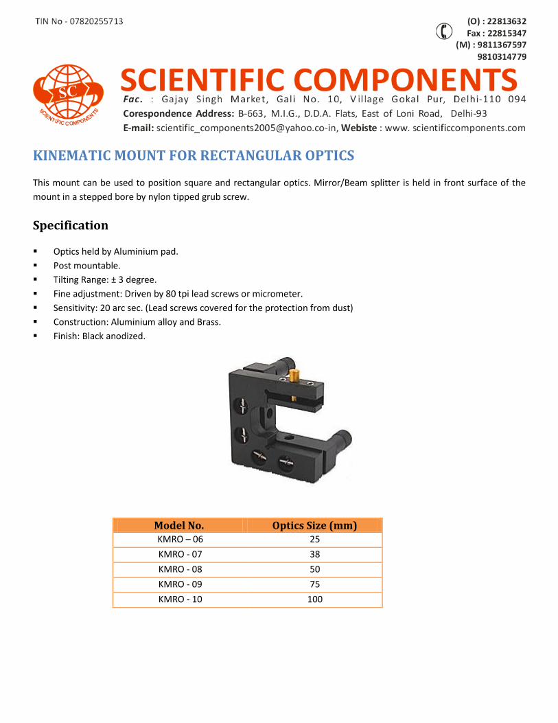
KINEMATIC MOUNT FOR RECTANGULAR OPTICS
This mount can be used to position square and rectangular optics. Mirror/Beam splitter is held in front surface of the
mount in a stepped bore by nylon tipped grub screw.
Specification
Optics held by Aluminium pad.
Post mountable.
Tilting Range: ± 3 degree.
Fine adjustment: Driven by 80 tpi lead screws or micrometer.
Sensitivity: 20 arc sec. (Lead screws covered for the protection from dust)
Construction: Aluminium alloy and Brass.
Finish: Black anodized.
Model No. Optics Size (mm) KMRO – 06 25
KMRO - 07 38
KMRO - 08 50
KMRO - 09 75
KMRO - 10 100
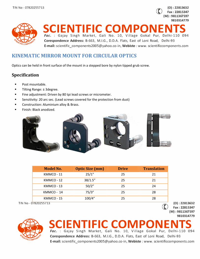
KINEMATIC MIRROR MOUNT FOR CIRCULAR OPTICS
Optics can be held in front surface of the mount in a stepped bore by nylon tipped grub screw.
Specification
Post mountable.
Tilting Range: ± 3degree.
Fine adjustment: Driven by 80 tpi lead screws or micrometer.
Sensitivity: 20 arc sec. (Lead screws covered for the protection from dust)
Construction: Aluminium alloy & Brass.
Finish: Black anodized.
Model No. Optic Size (mm) Drive Translation
KMMCO - 11 25/1" 25 21
KMMCO - 12 38/1.5” 25 21
KMMCO - 13 50/2” 25 24
KMMCO - 14 75/3” 25 28
KMMCO - 15 100/4” 25 28
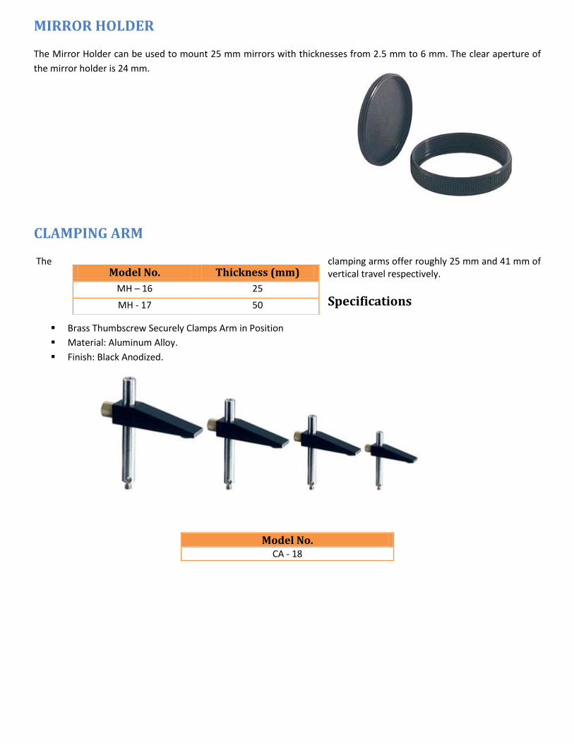
MIRROR HOLDER
The Mirror Holder can be used to mount 25 mm mirrors with thicknesses from 2.5 mm to 6 mm. The clear aperture of
the mirror holder is 24 mm.
CLAMPING ARM
The clamping arms offer roughly 25 mm and 41 mm of vertical travel respectively.
Specifications
Brass Thumbscrew Securely Clamps Arm in Position
Material: Aluminum Alloy.
Finish: Black Anodized.
Model No. Thickness (mm)
MH – 16 25
MH - 17 50
Model No. CA - 18
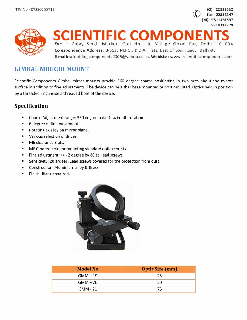
GIMBAL MIRROR MOUNT
Scientific Components Gimbal mirror mounts provide 360 degree coarse positioning in two axes about the mirror
surface in addition to fine adjustments. The device can be either base mounted or post mounted. Optics held in position
by a threaded ring inside a threaded bore of the device.
Specification
Coarse Adjustment range: 360 degree polar & azimuth rotation.
6 degree of fine movement.
Rotating axis lay on mirror plane.
Various selection of drives.
M6 clearance Slots.
M6 C’bored hole for mounting standard optic mounts.
Fine adjustment: +/ - 2 degree by 80 tpi lead screws.
Sensitivity: 20 arc sec. Lead screws covered for the protection from dust.
Construction: Aluminium alloy & Brass.
Finish: Black anodized.
Model No Optic Size (mm)
GMM – 19 25
GMM – 20 50
GMM - 21 75
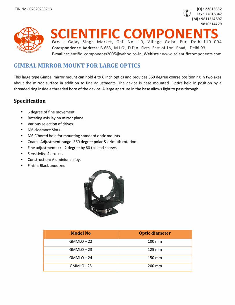
GIMBAL MIRROR MOUNT FOR LARGE OPTICS
This large type Gimbal mirror mount can hold 4 to 6 inch optics and provides 360 degree coarse positioning in two axes
about the mirror surface in addition to fine adjustments. The device is base mounted. Optics held in position by a
threaded ring inside a threaded bore of the device. A large aperture in the base allows light to pass through.
Specification
6 degree of fine movement.
Rotating axis lay on mirror plane.
Various selection of drives.
M6 clearance Slots.
M6 C’bored hole for mounting standard optic mounts.
Coarse Adjustment range: 360 degree polar & azimuth rotation.
Fine adjustment: +/ - 2 degree by 80 tpi lead screws.
Sensitivity: 4 arc sec.
Construction: Aluminium alloy.
Finish: Black anodized.
Model No Optic diameter
GMMLO – 22 100 mm
GMMLO – 23 125 mm
GMMLO – 24 150 mm
GMMLO - 25 200 mm
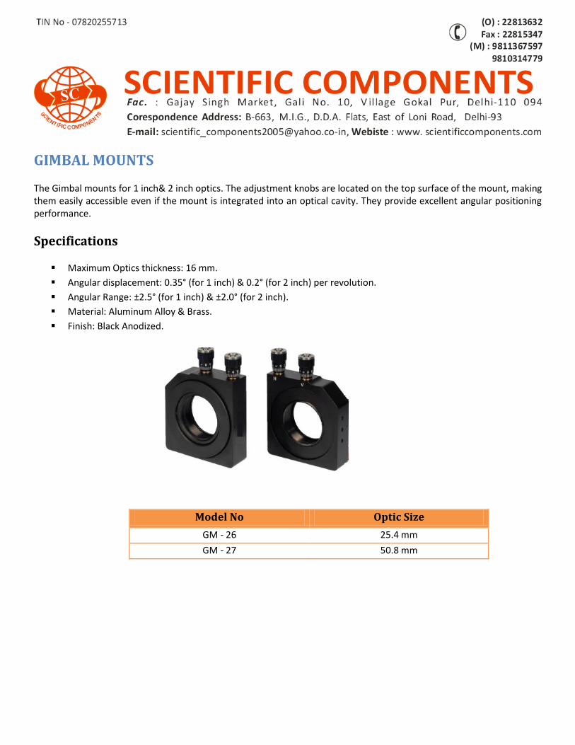
GIMBAL MOUNTS
The Gimbal mounts for 1 inch& 2 inch optics. The adjustment knobs are located on the top surface of the mount, making them easily accessible even if the mount is integrated into an optical cavity. They provide excellent angular positioning performance.
Specifications
Maximum Optics thickness: 16 mm.
Angular displacement: 0.35° (for 1 inch) & 0.2° (for 2 inch) per revolution.
Angular Range: ±2.5° (for 1 inch) & ±2.0° (for 2 inch).
Material: Aluminum Alloy & Brass.
Finish: Black Anodized.
Model No Optic Size
GM - 26 25.4 mm
GM - 27 50.8 mm
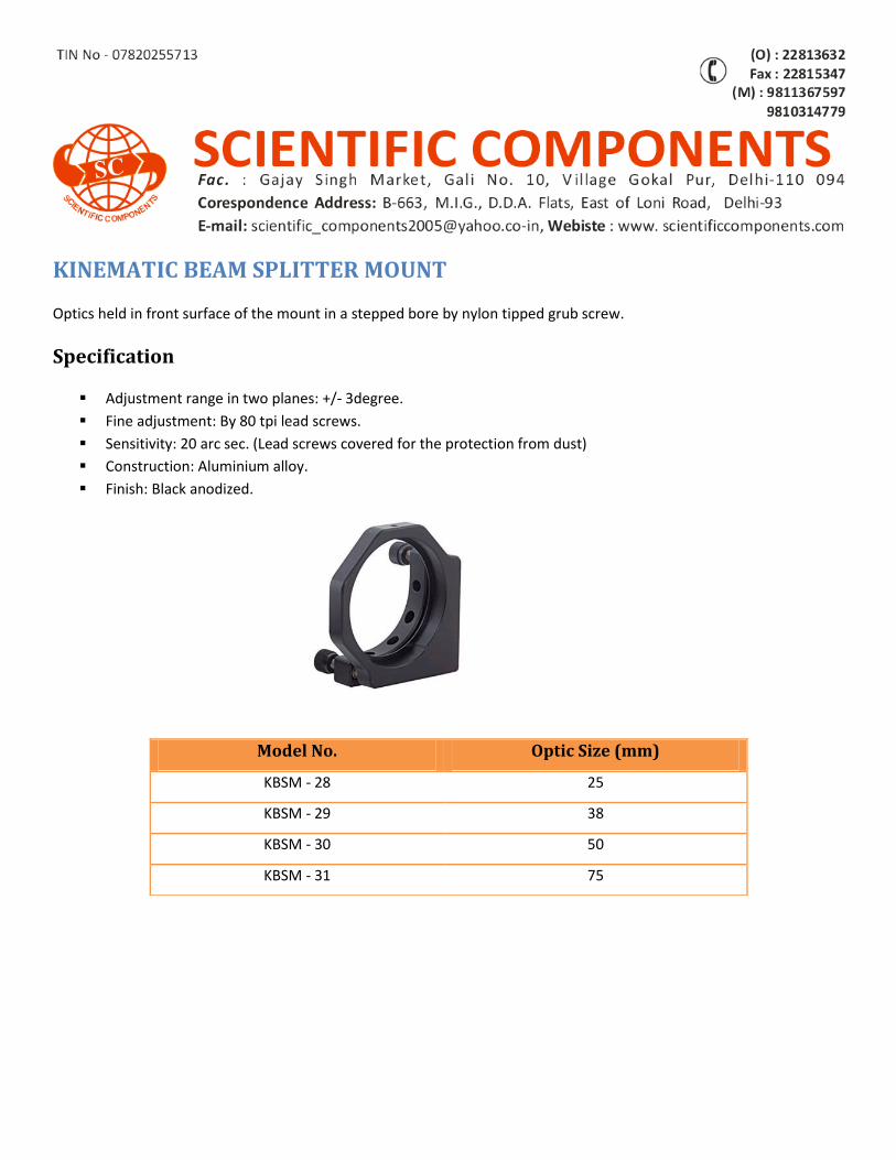
KINEMATIC BEAM SPLITTER MOUNT
Optics held in front surface of the mount in a stepped bore by nylon tipped grub screw.
Specification
Adjustment range in two planes: +/- 3degree.
Fine adjustment: By 80 tpi lead screws.
Sensitivity: 20 arc sec. (Lead screws covered for the protection from dust)
Construction: Aluminium alloy.
Finish: Black anodized.
Model No. Optic Size (mm)
KBSM - 28 25
KBSM - 29 38
KBSM - 30 50
KBSM - 31 75
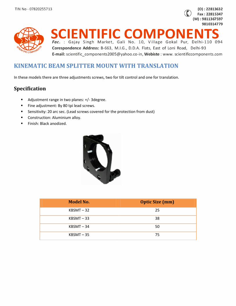
KINEMATIC BEAM SPLITTER MOUNT WITH TRANSLATION
In these models there are three adjustments screws, two for tilt control and one for translation.
Specification
Adjustment range in two planes: +/- 3degree.
Fine adjustment: By 80 tpi lead screws.
Sensitivity: 20 arc sec. (Lead screws covered for the protection from dust)
Construction: Aluminium alloy.
Finish: Black anodized.
Model No. Optic Size (mm)
KBSMT – 32 25
KBSMT – 33 38
KBSMT – 34 50
KBSMT – 35 75
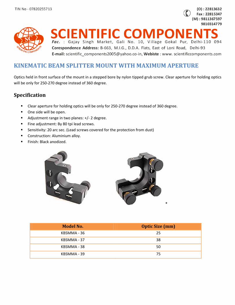
KINEMATIC BEAM SPLITTER MOUNT WITH MAXIMUM APERTURE
Optics held in front surface of the mount in a stepped bore by nylon tipped grub screw. Clear aperture for holding optics
will be only for 250-270 degree instead of 360 degree.
Specification
Clear aperture for holding optics will be only for 250-270 degree instead of 360 degree.
One side will be open.
Adjustment range in two planes: +/- 2 degree.
Fine adjustment: By 80 tpi lead screws.
Sensitivity: 20 arc sec. (Lead screws covered for the protection from dust)
Construction: Aluminium alloy.
Finish: Black anodized.
*
Model No. Optic Size (mm)
KBSMMA - 36 25
KBSMMA - 37 38
KBSMMA - 38 50
KBSMMA - 39 75
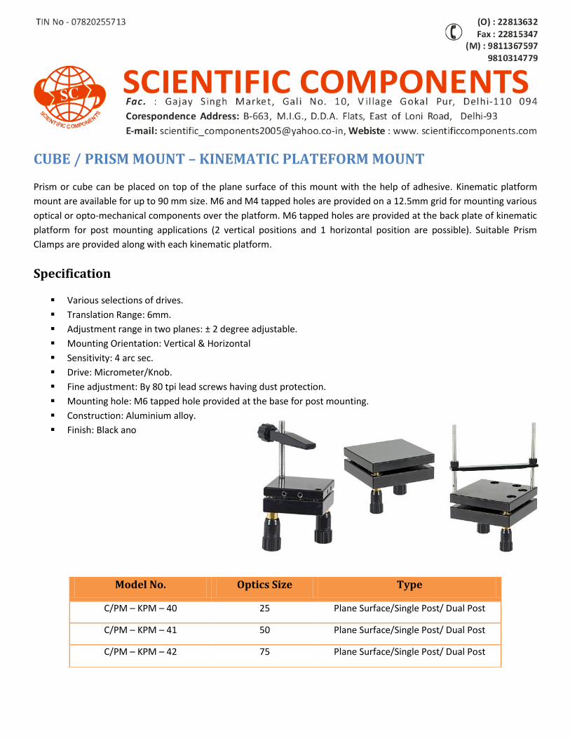
CUBE / PRISM MOUNT – KINEMATIC PLATEFORM MOUNT
Prism or cube can be placed on top of the plane surface of this mount with the help of adhesive. Kinematic platform
mount are available for up to 90 mm size. M6 and M4 tapped holes are provided on a 12.5mm grid for mounting various
optical or opto-mechanical components over the platform. M6 tapped holes are provided at the back plate of kinematic
platform for post mounting applications (2 vertical positions and 1 horizontal position are possible). Suitable Prism
Clamps are provided along with each kinematic platform.
Specification
Various selections of drives.
Translation Range: 6mm.
Adjustment range in two planes: ± 2 degree adjustable.
Mounting Orientation: Vertical & Horizontal
Sensitivity: 4 arc sec.
Drive: Micrometer/Knob.
Fine adjustment: By 80 tpi lead screws having dust protection.
Mounting hole: M6 tapped hole provided at the base for post mounting.
Construction: Aluminium alloy.
Finish: Black ano
Model No. Optics Size Type
C/PM – KPM – 40 25 Plane Surface/Single Post/ Dual Post
C/PM – KPM – 41 50 Plane Surface/Single Post/ Dual Post
C/PM – KPM – 42 75 Plane Surface/Single Post/ Dual Post
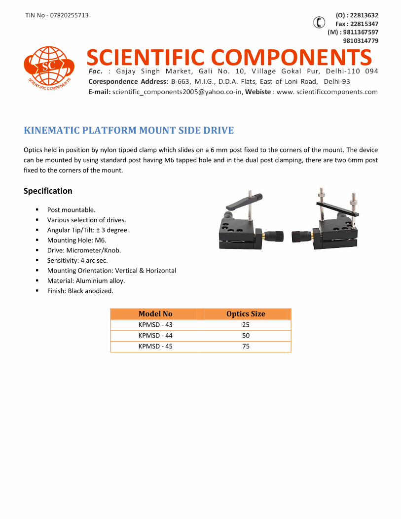
KINEMATIC PLATFORM MOUNT SIDE DRIVE
Optics held in position by nylon tipped clamp which slides on a 6 mm post fixed to the corners of the mount. The device
can be mounted by using standard post having M6 tapped hole and in the dual post clamping, there are two 6mm post
fixed to the corners of the mount.
Specification
Post mountable.
Various selection of drives.
Angular Tip/Tilt: ± 3 degree.
Mounting Hole: M6.
Drive: Micrometer/Knob.
Sensitivity: 4 arc sec.
Mounting Orientation: Vertical & Horizontal
Material: Aluminium alloy.
Finish: Black anodized.
Model No Optics Size
KPMSD - 43 25
KPMSD - 44 50
KPMSD - 45 75
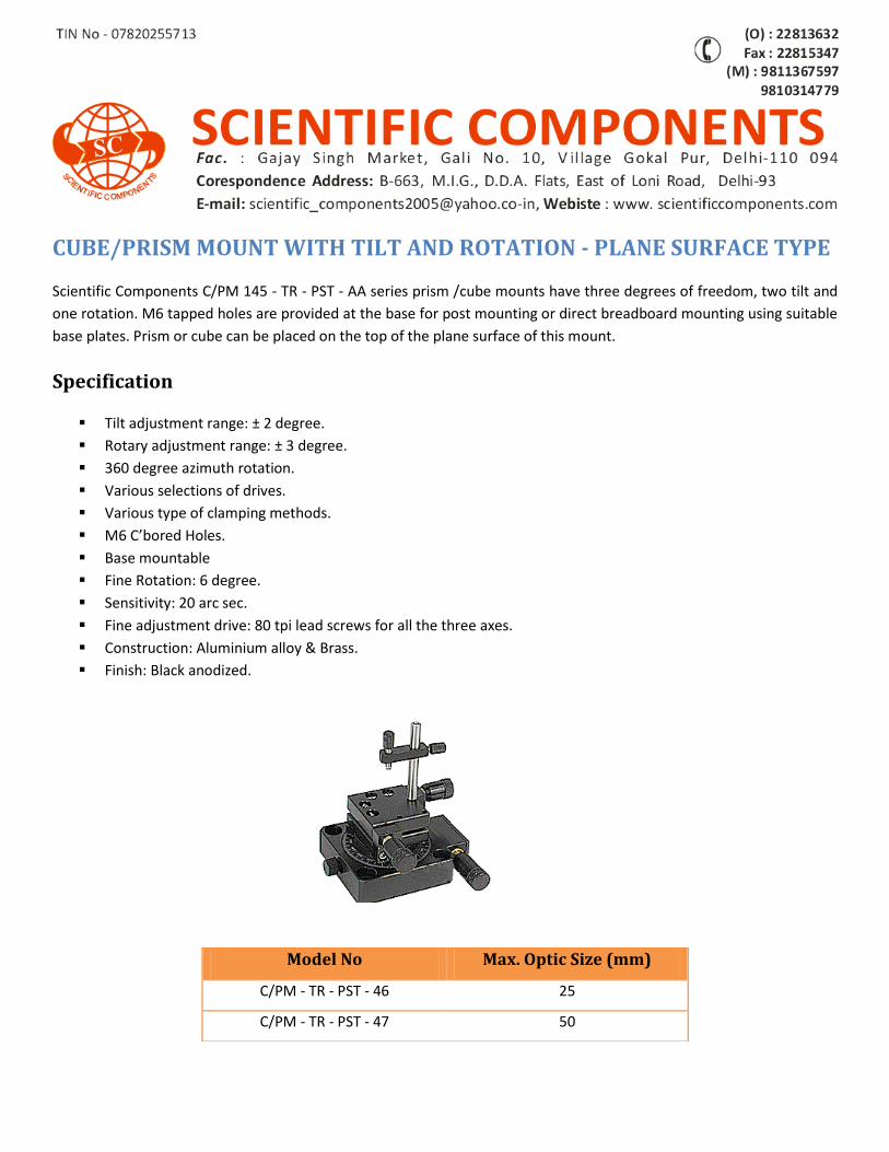
CUBE/PRISM MOUNT WITH TILT AND ROTATION - PLANE SURFACE TYPE
Scientific Components C/PM 145 - TR - PST - AA series prism /cube mounts have three degrees of freedom, two tilt and
one rotation. M6 tapped holes are provided at the base for post mounting or direct breadboard mounting using suitable
base plates. Prism or cube can be placed on the top of the plane surface of this mount.
Specification
Tilt adjustment range: ± 2 degree.
Rotary adjustment range: ± 3 degree.
360 degree azimuth rotation.
Various selections of drives.
Various type of clamping methods.
M6 C’bored Holes.
Base mountable
Fine Rotation: 6 degree.
Sensitivity: 20 arc sec.
Fine adjustment drive: 80 tpi lead screws for all the three axes.
Construction: Aluminium alloy & Brass.
Finish: Black anodized.
Model No Max. Optic Size (mm)
C/PM - TR - PST - 46 25
C/PM - TR - PST - 47 50
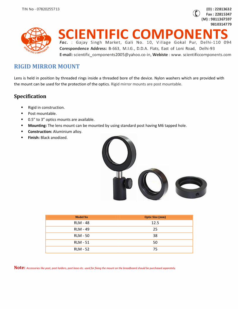
RIGID MIRROR MOUNT
Lens is held in position by threaded rings inside a threaded bore of the device. Nylon washers which are provided with
the mount can be used for the protection of the optics. Rigid mirror mounts are post mountable.
Specification
Rigid in construction.
Post mountable.
0.5” to 3” optics mounts are available.
Mounting: The lens mount can be mounted by using standard post having M6 tapped hole.
Construction: Aluminium alloy.
Finish: Black anodized.
Note: Accessories like post, post holders, post base etc. used for fixing the mount on the breadboard should be purchased separately.
Model No Optic Size (mm)
RLM - 48 12.5
RLM - 49 25
RLM - 50 38
RLM - 51 50
RLM - 52 75
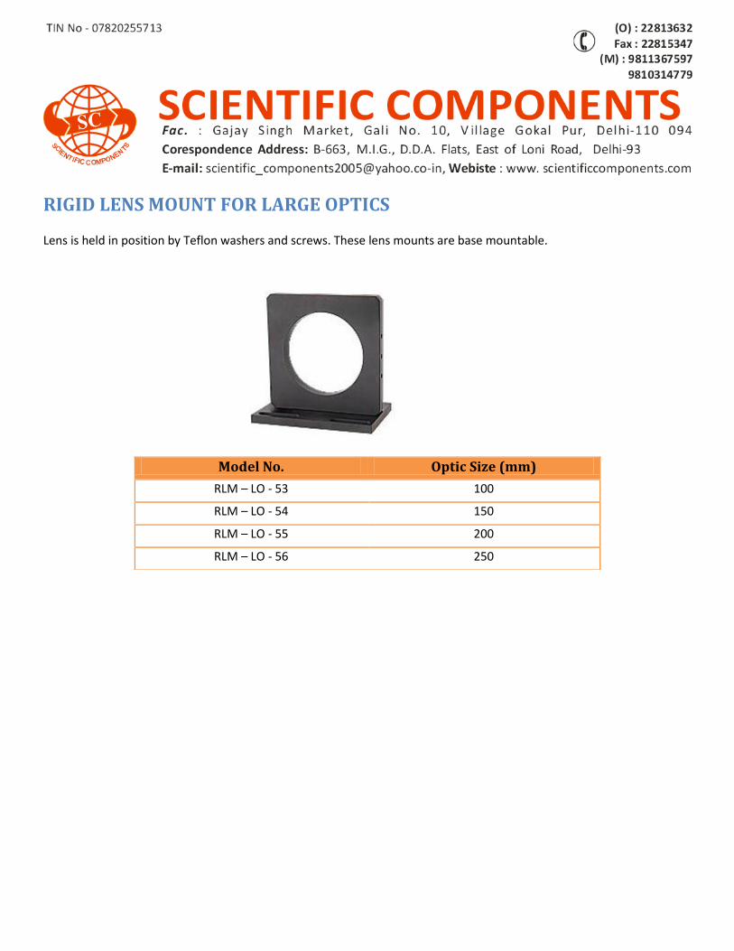
RIGID LENS MOUNT FOR LARGE OPTICS
Lens is held in position by Teflon washers and screws. These lens mounts are base mountable.
Model No. Optic Size (mm)
RLM – LO - 53 100
RLM – LO - 54 150
RLM – LO - 55 200
RLM – LO - 56 250
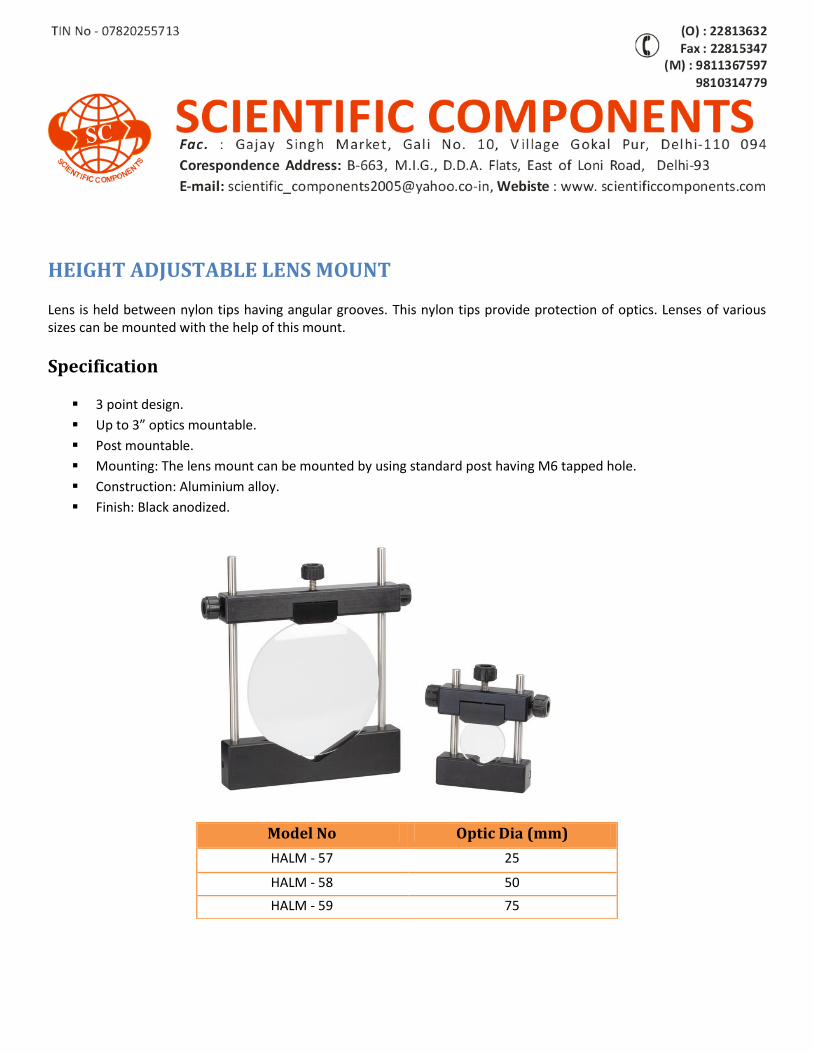
HEIGHT ADJUSTABLE LENS MOUNT
Lens is held between nylon tips having angular grooves. This nylon tips provide protection of optics. Lenses of various sizes can be mounted with the help of this mount.
Specification
3 point design.
Up to 3” optics mountable.
Post mountable.
Mounting: The lens mount can be mounted by using standard post having M6 tapped hole.
Construction: Aluminium alloy.
Finish: Black anodized.
Model No Optic Dia (mm)
HALM - 57 25
HALM - 58 50
HALM - 59 75
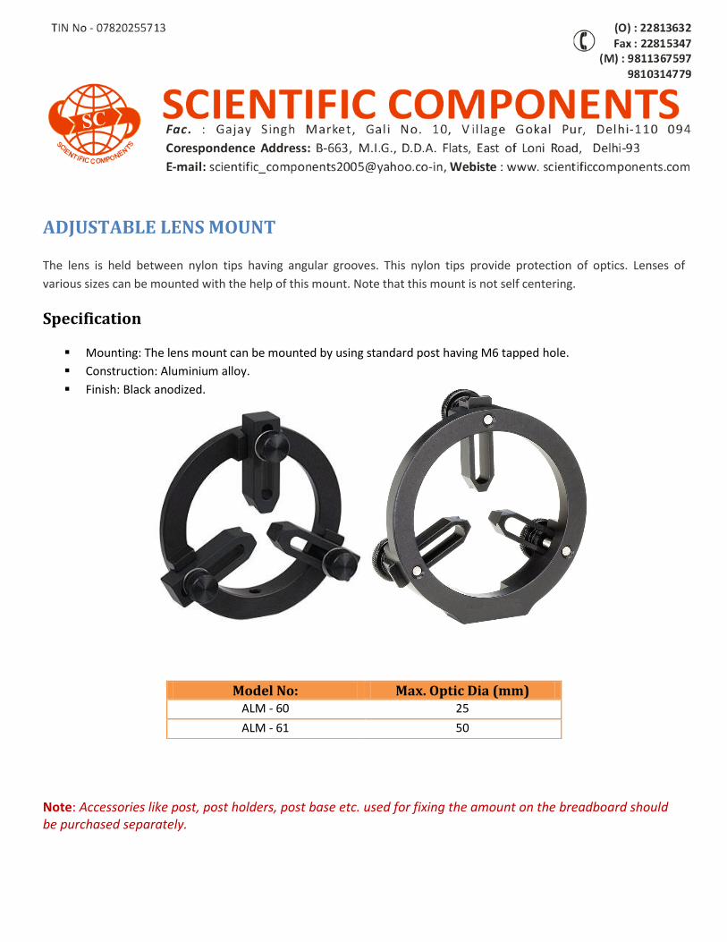
ADJUSTABLE LENS MOUNT
The lens is held between nylon tips having angular grooves. This nylon tips provide protection of optics. Lenses of
various sizes can be mounted with the help of this mount. Note that this mount is not self centering.
Specification
Mounting: The lens mount can be mounted by using standard post having M6 tapped hole.
Construction: Aluminium alloy.
Finish: Black anodized.
Note: Accessories like post, post holders, post base etc. used for fixing the amount on the breadboard should be purchased separately.
Model No: Max. Optic Dia (mm) ALM - 60 25
ALM - 61 50
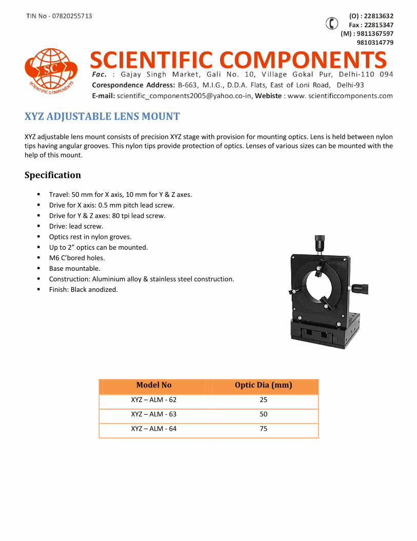
XYZ ADJUSTABLE LENS MOUNT
XYZ adjustable lens mount consists of precision XYZ stage with provision for mounting optics. Lens is held between nylon tips having angular grooves. This nylon tips provide protection of optics. Lenses of various sizes can be mounted with the help of this mount.
Specification
Travel: 50 mm for X axis, 10 mm for Y & Z axes.
Drive for X axis: 0.5 mm pitch lead screw.
Drive for Y & Z axes: 80 tpi lead screw.
Drive: lead screw.
Optics rest in nylon groves.
Up to 2” optics can be mounted.
M6 C’bored holes.
Base mountable.
Construction: Aluminium alloy & stainless steel construction.
Finish: Black anodized.
Model No Optic Dia (mm)
XYZ – ALM - 62 25
XYZ – ALM - 63 50
XYZ – ALM - 64 75
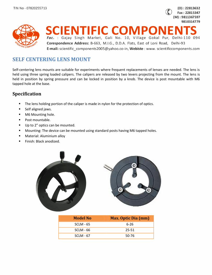
SELF CENTERING LENS MOUNT
Self-centering lens mounts are suitable for experiments where frequent replacements of lenses are needed. The lens is held using three spring loaded calipers. The calipers are released by two levers projecting from the mount. The lens is held in position by spring pressure and can be locked in position by a knob. The device is post mountable with M6 tapped hole at the base.
Specification
The lens holding portion of the caliper is made in nylon for the protection of optics.
Self aligned jaws.
M6 Mounting hole.
Post mountable.
Up to 2” optics can be mounted.
Mounting: The device can be mounted using standard posts having M6 tapped holes.
Material: Aluminium alloy
Finish: Black anodized.
Model No Max. Optic Dia (mm)
SCLM - 65 6-26
SCLM - 66 25-51
SCLM - 67 50-76
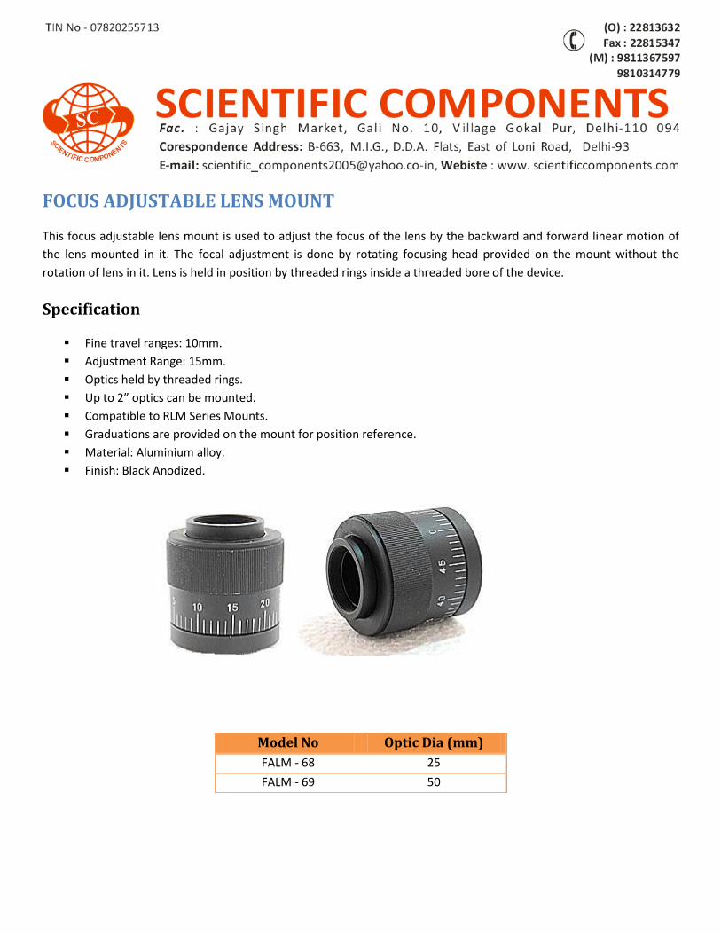
FOCUS ADJUSTABLE LENS MOUNT
This focus adjustable lens mount is used to adjust the focus of the lens by the backward and forward linear motion of
the lens mounted in it. The focal adjustment is done by rotating focusing head provided on the mount without the
rotation of lens in it. Lens is held in position by threaded rings inside a threaded bore of the device.
Specification
Fine travel ranges: 10mm.
Adjustment Range: 15mm.
Optics held by threaded rings.
Up to 2” optics can be mounted.
Compatible to RLM Series Mounts.
Graduations are provided on the mount for position reference.
Material: Aluminium alloy.
Finish: Black Anodized.
Model No Optic Dia (mm)
FALM - 68 25
FALM - 69 50
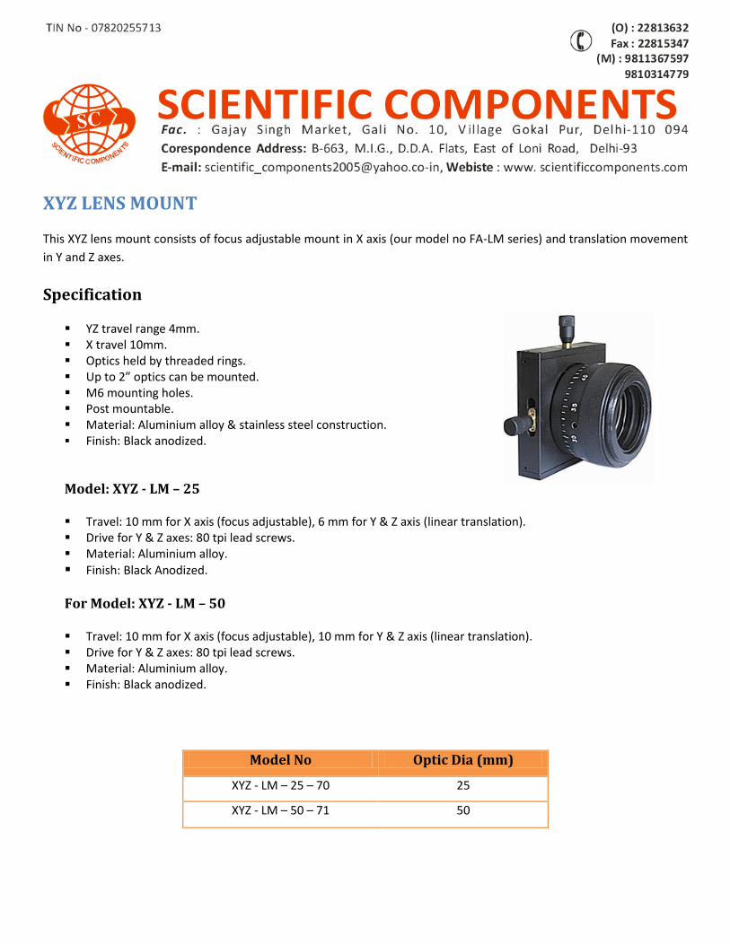
XYZ LENS MOUNT
This XYZ lens mount consists of focus adjustable mount in X axis (our model no FA-LM series) and translation movement
in Y and Z axes.
Specification
YZ travel range 4mm. X travel 10mm. Optics held by threaded rings. Up to 2” optics can be mounted. M6 mounting holes. Post mountable. Material: Aluminium alloy & stainless steel construction. Finish: Black anodized.
Model: XYZ - LM – 25
Travel: 10 mm for X axis (focus adjustable), 6 mm for Y & Z axis (linear translation). Drive for Y & Z axes: 80 tpi lead screws. Material: Aluminium alloy.
Finish: Black Anodized.
For Model: XYZ - LM – 50
Travel: 10 mm for X axis (focus adjustable), 10 mm for Y & Z axis (linear translation). Drive for Y & Z axes: 80 tpi lead screws. Material: Aluminium alloy. Finish: Black anodized.
Model No Optic Dia (mm)
XYZ - LM – 25 – 70 25
XYZ - LM – 50 – 71 50
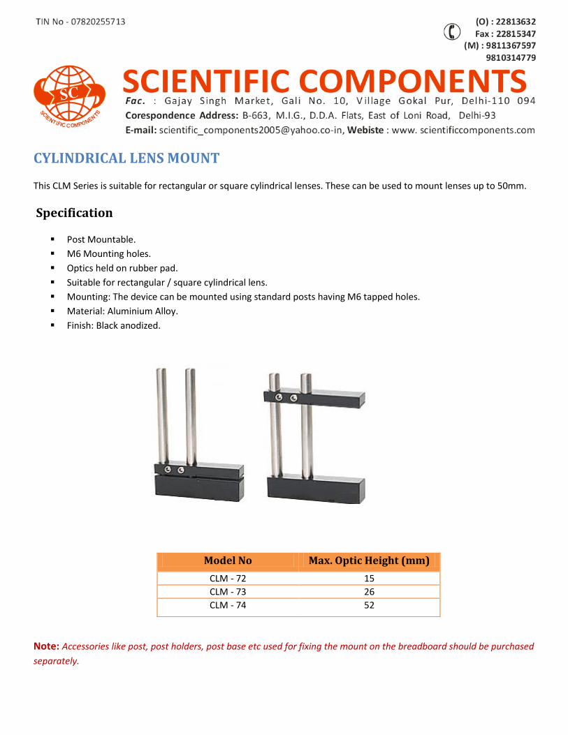
CYLINDRICAL LENS MOUNT
This CLM Series is suitable for rectangular or square cylindrical lenses. These can be used to mount lenses up to 50mm.
Specification
Post Mountable.
M6 Mounting holes.
Optics held on rubber pad.
Suitable for rectangular / square cylindrical lens.
Mounting: The device can be mounted using standard posts having M6 tapped holes.
Material: Aluminium Alloy.
Finish: Black anodized.
Note: Accessories like post, post holders, post base etc used for fixing the mount on the breadboard should be purchased
separately.
Model No Max. Optic Height (mm)
CLM - 72 15
CLM - 73 26
CLM - 74 52
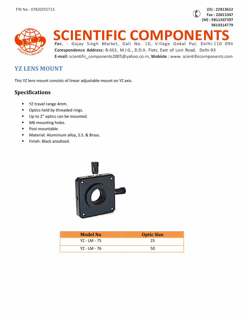
YZ LENS MOUNT
This YZ lens mount consists of linear adjustable mount on YZ axis.
Specifications
YZ travel range 4mm.
Optics held by threaded rings.
Up to 2” optics can be mounted.
M6 mounting holes.
Post mountable.
Material: Aluminium alloy, S.S. & Brass.
Finish: Black anodized.
Model No Optic Size YZ - LM - 75 25
YZ - LM - 76 50
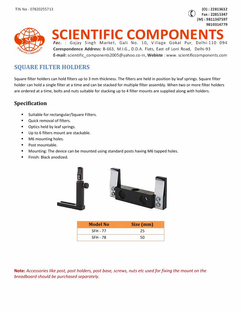
SQUARE FILTER HOLDERS
Square filter holders can hold filters up to 3 mm thickness. The filters are held in position by leaf springs. Square filter
holder can hold a single filter at a time and can be stacked for multiple filter assembly. When two or more filter holders
are ordered at a time, bolts and nuts suitable for stacking up to 4 filter mounts are supplied along with holders.
Specification
Suitable for rectangular/Square Filters.
Quick removal of filters.
Optics held by leaf springs.
Up to 6 filters mount are stackable.
M6 mounting holes.
Post mountable.
Mounting: The device can be mounted using standard posts having M6 tapped holes.
Finish: Black anodized.
Note: Accessories like post, post holders, post base, screws, nuts etc used for fixing the mount on the breadboard should be purchased separately.
Model No Size (mm)
SFH - 77 25
SFH - 78 50
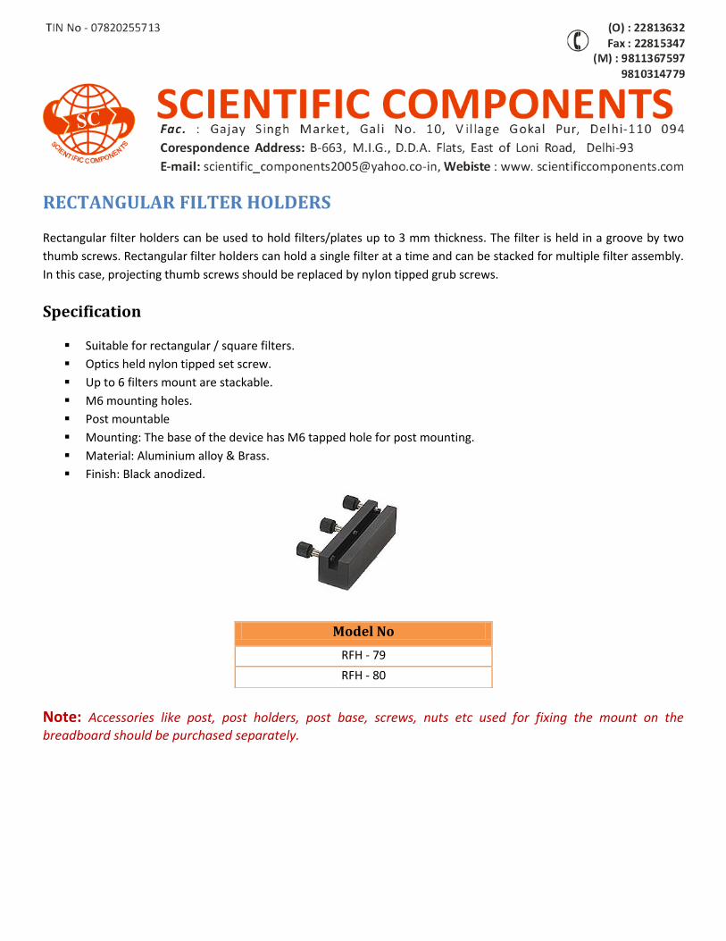
RECTANGULAR FILTER HOLDERS
Rectangular filter holders can be used to hold filters/plates up to 3 mm thickness. The filter is held in a groove by two
thumb screws. Rectangular filter holders can hold a single filter at a time and can be stacked for multiple filter assembly.
In this case, projecting thumb screws should be replaced by nylon tipped grub screws.
Specification
Suitable for rectangular / square filters.
Optics held nylon tipped set screw.
Up to 6 filters mount are stackable.
M6 mounting holes.
Post mountable
Mounting: The base of the device has M6 tapped hole for post mounting.
Material: Aluminium alloy & Brass.
Finish: Black anodized.
Note: Accessories like post, post holders, post base, screws, nuts etc used for fixing the mount on the breadboard should be purchased separately.
Model No
RFH - 79
RFH - 80
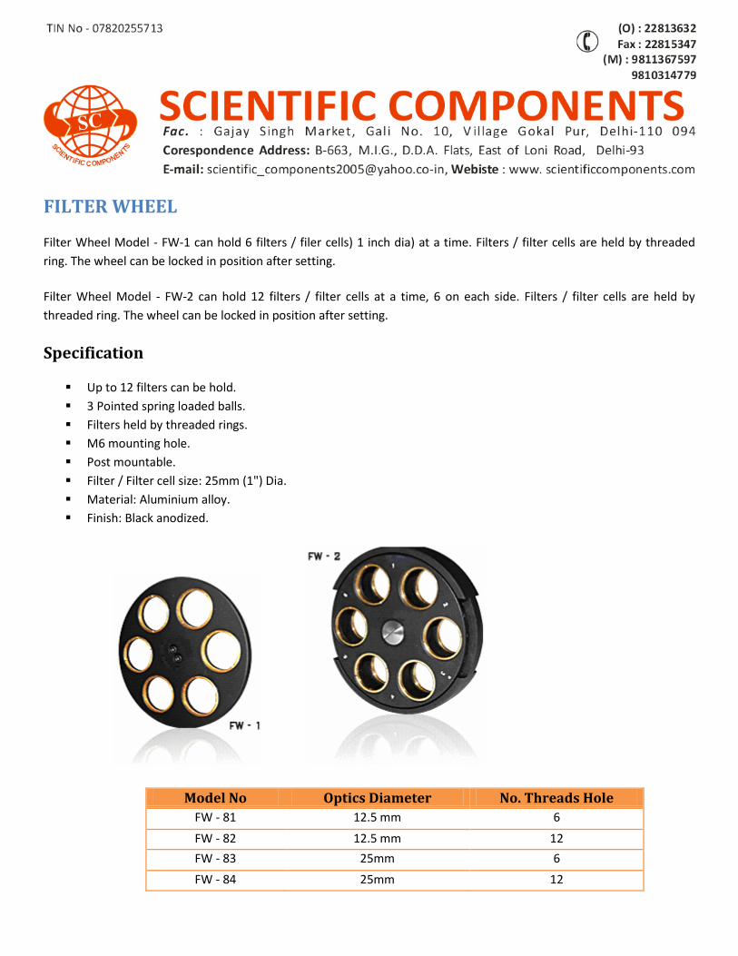
FILTER WHEEL
Filter Wheel Model - FW-1 can hold 6 filters / filer cells) 1 inch dia) at a time. Filters / filter cells are held by threaded
ring. The wheel can be locked in position after setting.
Filter Wheel Model - FW-2 can hold 12 filters / filter cells at a time, 6 on each side. Filters / filter cells are held by
threaded ring. The wheel can be locked in position after setting.
Specification
Up to 12 filters can be hold.
3 Pointed spring loaded balls.
Filters held by threaded rings.
M6 mounting hole.
Post mountable.
Filter / Filter cell size: 25mm (1") Dia.
Material: Aluminium alloy.
Finish: Black anodized.
Model No Optics Diameter No. Threads Hole
FW - 81 12.5 mm 6
FW - 82 12.5 mm 12
FW - 83 25mm 6
FW - 84 25mm 12
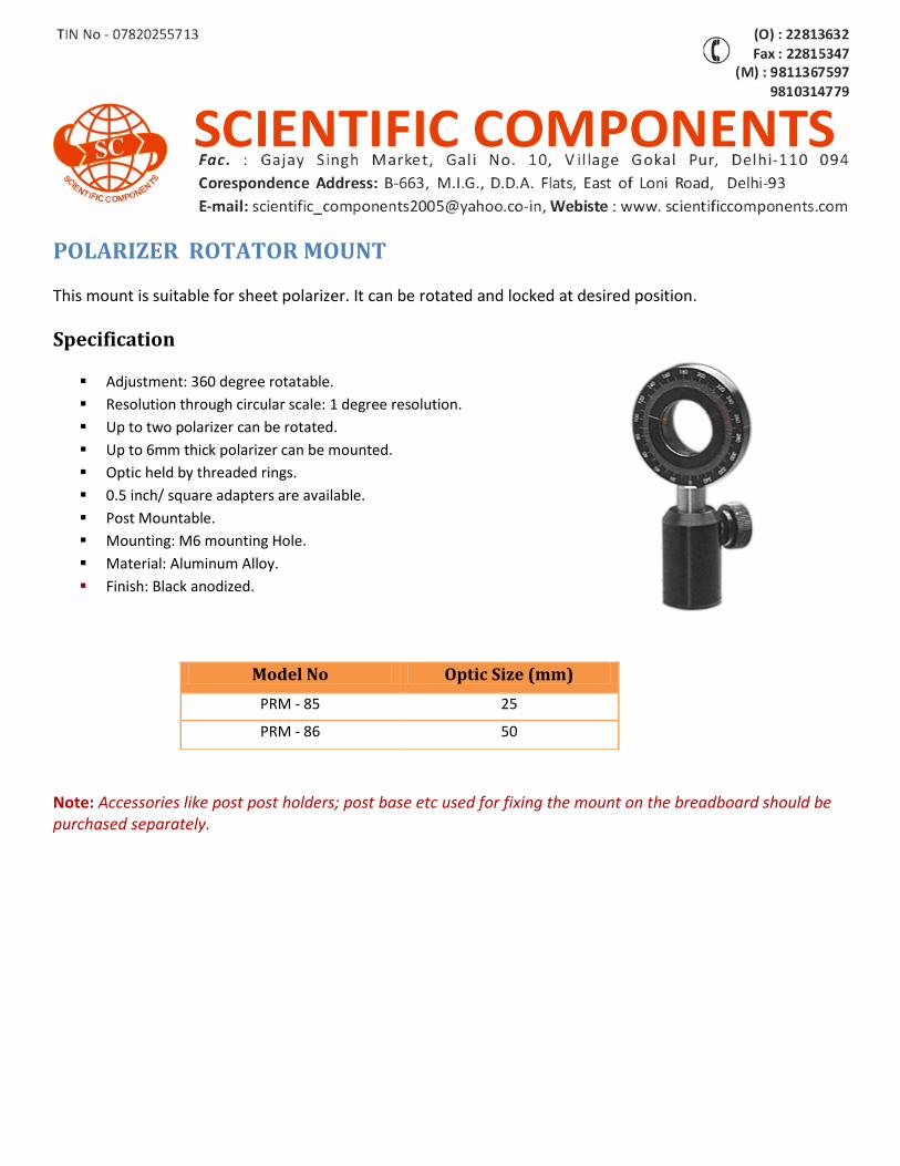
POLARIZER ROTATOR MOUNT
This mount is suitable for sheet polarizer. It can be rotated and locked at desired position.
Specification
Adjustment: 360 degree rotatable.
Resolution through circular scale: 1 degree resolution.
Up to two polarizer can be rotated.
Up to 6mm thick polarizer can be mounted.
Optic held by threaded rings.
0.5 inch/ square adapters are available.
Post Mountable.
Mounting: M6 mounting Hole.
Material: Aluminum Alloy.
Finish: Black anodized.
Note: Accessories like post post holders; post base etc used for fixing the mount on the breadboard should be purchased separately.
Model No Optic Size (mm)
PRM - 85 25
PRM - 86 50
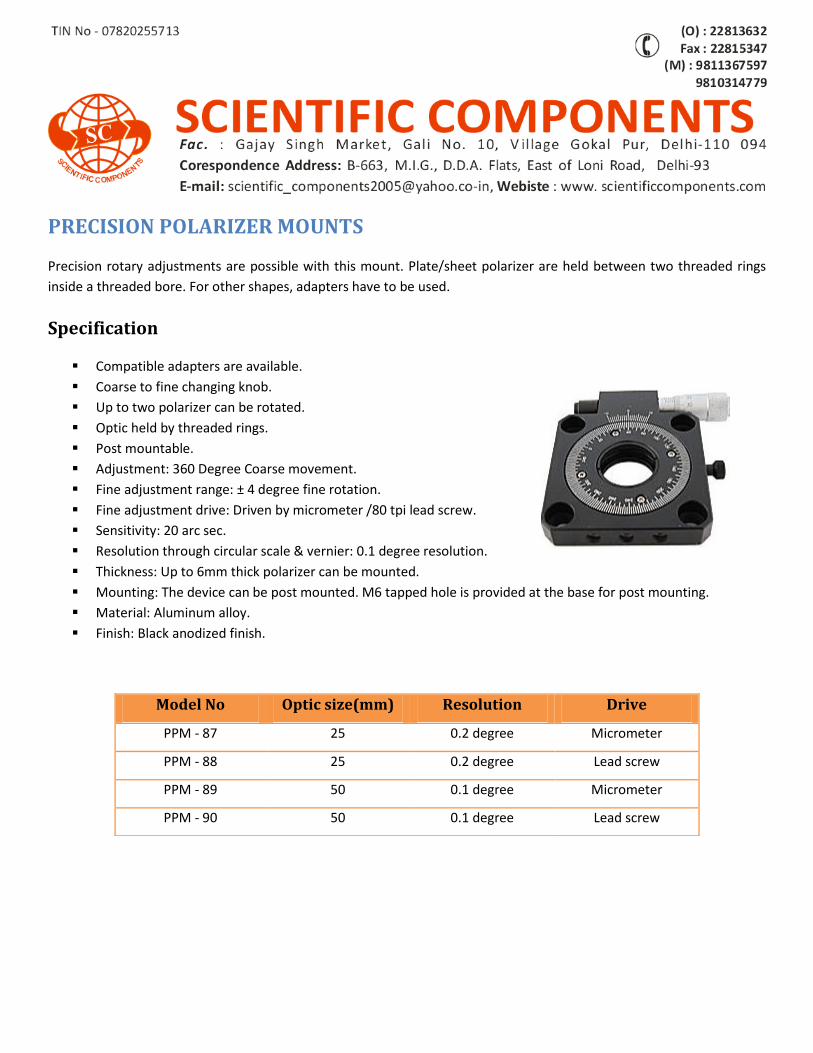
PRECISION POLARIZER MOUNTS
Precision rotary adjustments are possible with this mount. Plate/sheet polarizer are held between two threaded rings
inside a threaded bore. For other shapes, adapters have to be used.
Specification
Compatible adapters are available.
Coarse to fine changing knob.
Up to two polarizer can be rotated.
Optic held by threaded rings.
Post mountable.
Adjustment: 360 Degree Coarse movement.
Fine adjustment range: ± 4 degree fine rotation.
Fine adjustment drive: Driven by micrometer /80 tpi lead screw.
Sensitivity: 20 arc sec.
Resolution through circular scale & vernier: 0.1 degree resolution.
Thickness: Up to 6mm thick polarizer can be mounted.
Mounting: The device can be post mounted. M6 tapped hole is provided at the base for post mounting.
Material: Aluminum alloy.
Finish: Black anodized finish.
Model No Optic size(mm) Resolution Drive
PPM - 87 25 0.2 degree Micrometer
PPM - 88 25 0.2 degree Lead screw
PPM - 89 50 0.1 degree Micrometer
PPM - 90 50 0.1 degree Lead screw
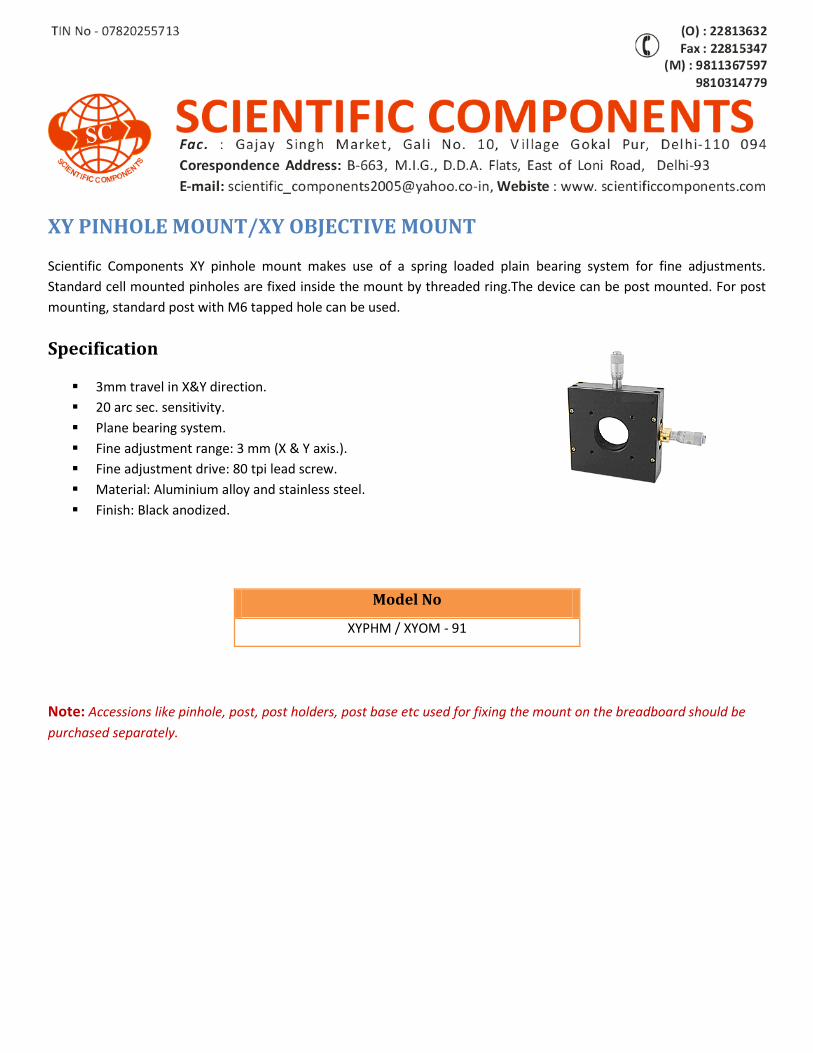
XY PINHOLE MOUNT/XY OBJECTIVE MOUNT
Scientific Components XY pinhole mount makes use of a spring loaded plain bearing system for fine adjustments.
Standard cell mounted pinholes are fixed inside the mount by threaded ring.The device can be post mounted. For post
mounting, standard post with M6 tapped hole can be used.
Specification
3mm travel in X&Y direction.
20 arc sec. sensitivity.
Plane bearing system.
Fine adjustment range: 3 mm (X & Y axis.).
Fine adjustment drive: 80 tpi lead screw.
Material: Aluminium alloy and stainless steel.
Finish: Black anodized.
Note: Accessions like pinhole, post, post holders, post base etc used for fixing the mount on the breadboard should be
purchased separately.
Model No
XYPHM / XYOM - 91
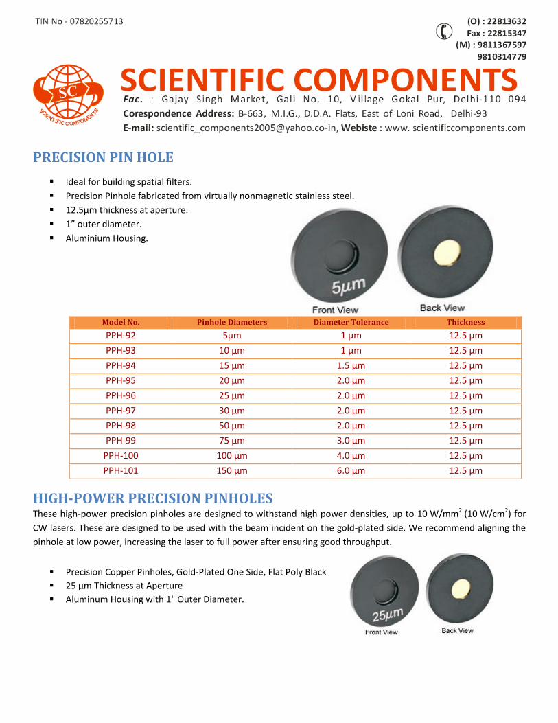
PRECISION PIN HOLE
Ideal for building spatial filters.
Precision Pinhole fabricated from virtually nonmagnetic stainless steel.
12.5µm thickness at aperture.
1” outer diameter.
Aluminium Housing.
Model No. Pinhole Diameters Diameter Tolerance Thickness
PPH-92 5µm 1 µm 12.5 µm
PPH-93 10 µm 1 µm 12.5 µm
PPH-94 15 µm 1.5 µm 12.5 µm
PPH-95 20 µm 2.0 µm 12.5 µm
PPH-96 25 µm 2.0 µm 12.5 µm
PPH-97 30 µm 2.0 µm 12.5 µm
PPH-98 50 µm 2.0 µm 12.5 µm
PPH-99 75 µm 3.0 µm 12.5 µm
PPH-100 100 µm 4.0 µm 12.5 µm
PPH-101 150 µm 6.0 µm 12.5 µm
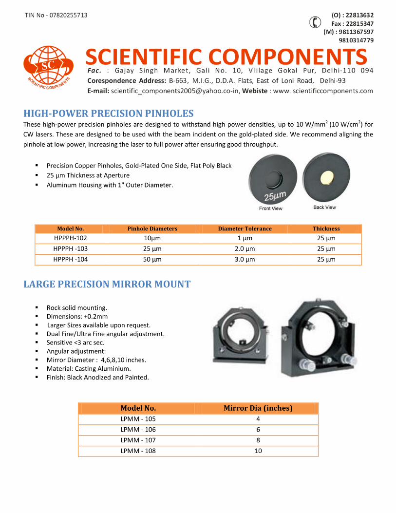
HIGH-POWER PRECISION PINHOLES These high-power precision pinholes are designed to withstand high power densities, up to 10 W/mm2 (10 W/cm2) for
CW lasers. These are designed to be used with the beam incident on the gold-plated side. We recommend aligning the
pinhole at low power, increasing the laser to full power after ensuring good throughput.
Precision Copper Pinholes, Gold-Plated One Side, Flat Poly Black
25 µm Thickness at Aperture
Aluminum Housing with 1" Outer Diameter.
LARGE PRECISION MIRROR MOUNT
Rock solid mounting. Dimensions: +0.2mm Larger Sizes available upon request. Dual Fine/Ultra Fine angular adjustment. Sensitive <3 arc sec. Angular adjustment: Mirror Diameter : 4,6,8,10 inches. Material: Casting Aluminium. Finish: Black Anodized and Painted.
Model No. Pinhole Diameters Diameter Tolerance Thickness
HPPPH-102 10µm 1 µm 25 µm
HPPPH -103 25 µm 2.0 µm 25 µm
HPPPH -104 50 µm 3.0 µm 25 µm
Model No. Mirror Dia (inches)
LPMM - 105 4
LPMM - 106 6
LPMM - 107 8
LPMM - 108 10
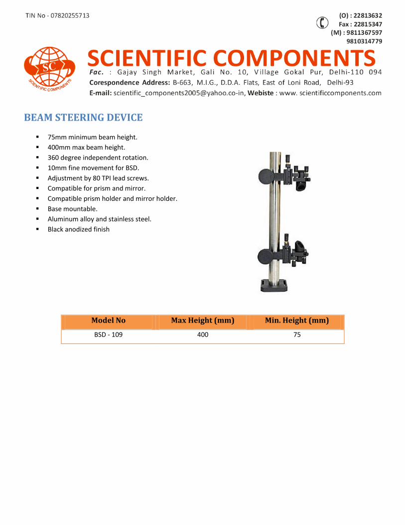
BEAM STEERING DEVICE
75mm minimum beam height.
400mm max beam height.
360 degree independent rotation.
10mm fine movement for BSD.
Adjustment by 80 TPI lead screws.
Compatible for prism and mirror.
Compatible prism holder and mirror holder.
Base mountable.
Aluminum alloy and stainless steel.
Black anodized finish
Model No Max Height (mm) Min. Height (mm)
BSD - 109 400 75
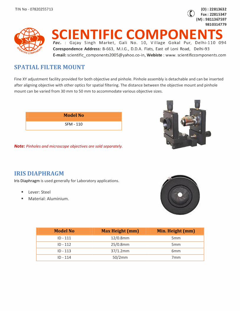
SPATIAL FILTER MOUNT Fine XY adjustment facility provided for both objective and pinhole. Pinhole assembly is detachable and can be inserted
after aligning objective with other optics for spatial filtering. The distance between the objective mount and pinhole
mount can be varied from 30 mm to 50 mm to accommodate various objective sizes.
Note: Pinholes and microscope objectives are sold separately.
IRIS DIAPHRAGM Iris Diaphragm is used generally for Laboratory applications.
Lever: Steel
Material: Aluminium.
Model No
SFM - 110
Model No Max Height (mm) Min. Height (mm)
ID - 111 12/0.8mm 5mm
ID - 112 25/0.8mm 5mm
ID - 113 37/1.2mm 6mm
ID - 114 50/2mm 7mm
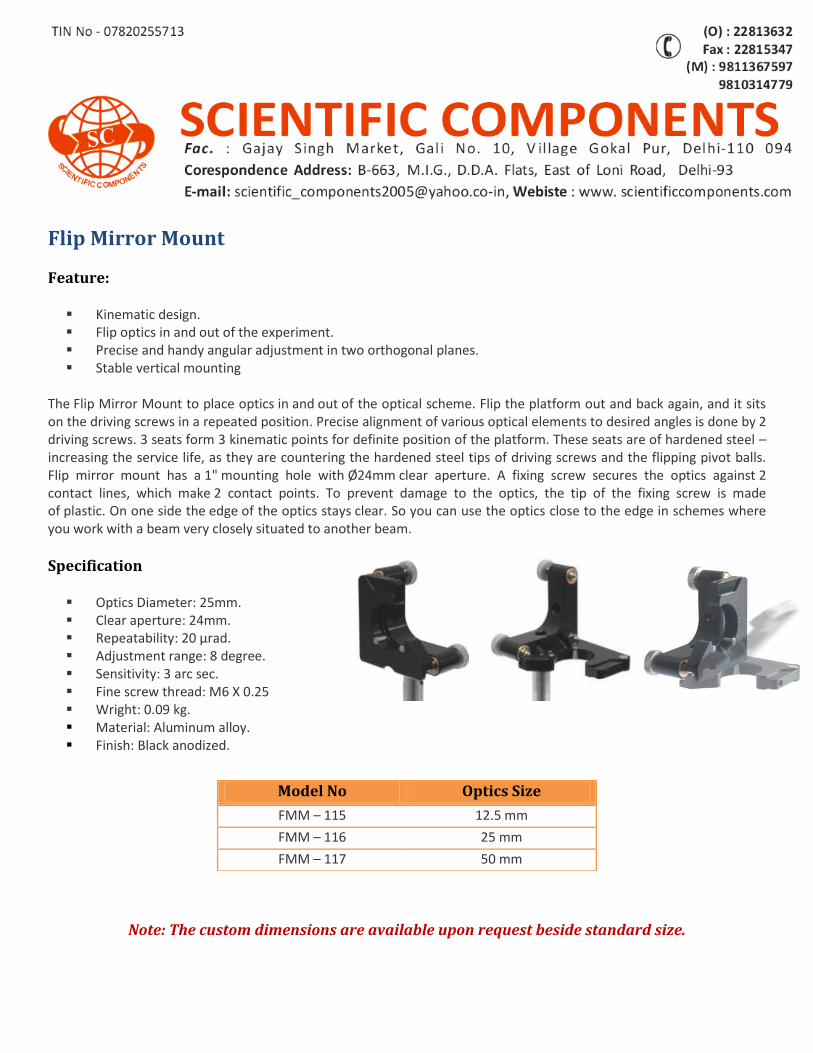
Flip Mirror Mount
Feature: Kinematic design. Flip optics in and out of the experiment. Precise and handy angular adjustment in two orthogonal planes. Stable vertical mounting
The Flip Mirror Mount to place optics in and out of the optical scheme. Flip the platform out and back again, and it sits on the driving screws in a repeated position. Precise alignment of various optical elements to desired angles is done by 2 driving screws. 3 seats form 3 kinematic points for definite position of the platform. These seats are of hardened steel – increasing the service life, as they are countering the hardened steel tips of driving screws and the flipping pivot balls. Flip mirror mount has a 1" mounting hole with Ø24mm clear aperture. A fixing screw secures the optics against 2 contact lines, which make 2 contact points. To prevent damage to the optics, the tip of the fixing screw is made of plastic. On one side the edge of the optics stays clear. So you can use the optics close to the edge in schemes where you work with a beam very closely situated to another beam.
Specification Optics Diameter: 25mm. Clear aperture: 24mm. Repeatability: 20 µrad. Adjustment range: 8 degree. Sensitivity: 3 arc sec. Fine screw thread: M6 X 0.25 Wright: 0.09 kg. Material: Aluminum alloy. Finish: Black anodized.
Note: The custom dimensions are available upon request beside standard size.
Model No Optics Size
FMM – 115 12.5 mm
FMM – 116 25 mm
FMM – 117 50 mm
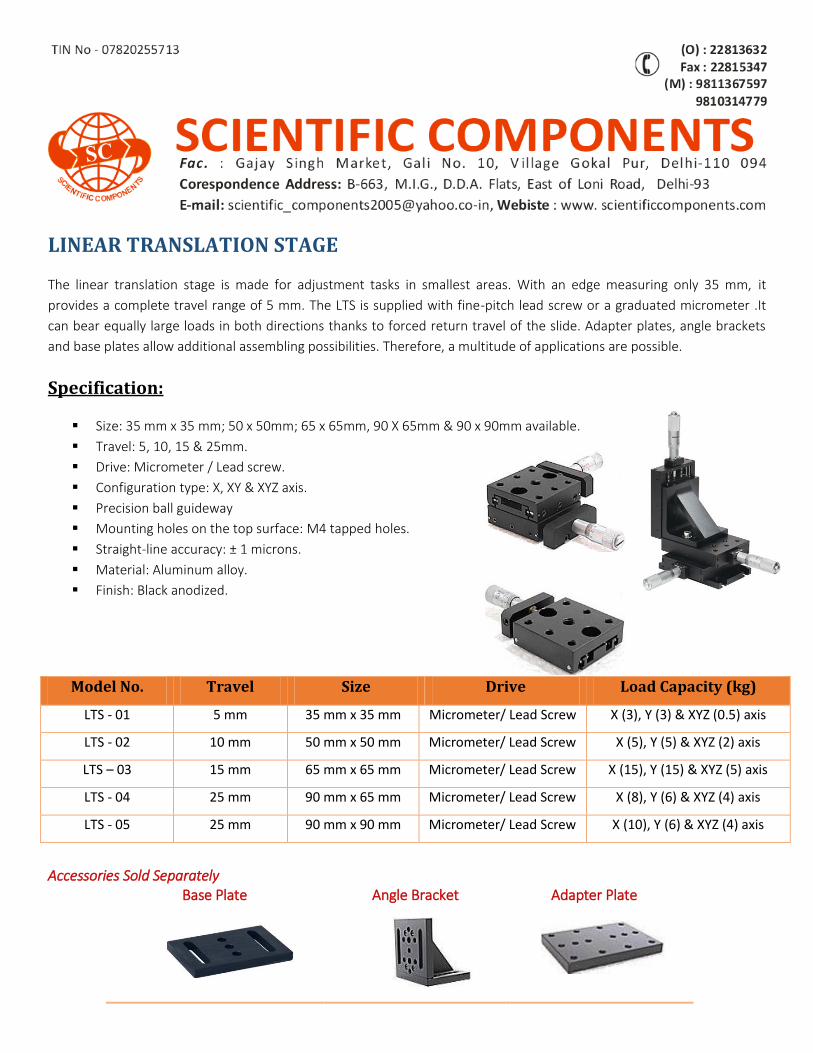
LINEAR TRANSLATION STAGE
The linear translation stage is made for adjustment tasks in smallest areas. With an edge measuring only 35 mm, it
provides a complete travel range of 5 mm. The LTS is supplied with fine-pitch lead screw or a graduated micrometer .It
can bear equally large loads in both directions thanks to forced return travel of the slide. Adapter plates, angle brackets
and base plates allow additional assembling possibilities. Therefore, a multitude of applications are possible.
Specification:
Size: 35 mm x 35 mm; 50 x 50mm; 65 x 65mm, 90 X 65mm & 90 x 90mm available.
Travel: 5, 10, 15 & 25mm.
Drive: Micrometer / Lead screw.
Configuration type: X, XY & XYZ axis.
Precision ball guideway
Mounting holes on the top surface: M4 tapped holes.
Straight-line accuracy: ± 1 microns.
Material: Aluminum alloy.
Finish: Black anodized.
Accessories Sold Separately Base Plate
Angle Bracket Adapter Plate
Model No. Travel Size Drive Load Capacity (kg)
LTS - 01 5 mm 35 mm x 35 mm Micrometer/ Lead Screw X (3), Y (3) & XYZ (0.5) axis
LTS - 02 10 mm 50 mm x 50 mm Micrometer/ Lead Screw X (5), Y (5) & XYZ (2) axis
LTS – 03 15 mm 65 mm x 65 mm Micrometer/ Lead Screw X (15), Y (15) & XYZ (5) axis
LTS - 04 25 mm 90 mm x 65 mm Micrometer/ Lead Screw X (8), Y (6) & XYZ (4) axis
LTS - 05 25 mm 90 mm x 90 mm Micrometer/ Lead Screw X (10), Y (6) & XYZ (4) axis
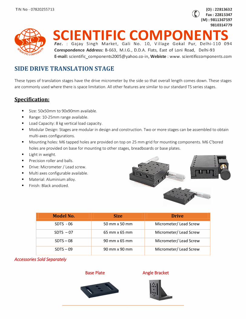
SIDE DRIVE TRANSLATION STAGE
These types of translation stages have the drive micrometer by the side so that overall length comes down. These stages
are commonly used where there is space limitation. All other features are similar to our standard TS series stages.
Specification:
Size: 50x50mm to 90x90mm available.
Range: 10-25mm range available.
Load Capacity: 8 kg vertical load capacity.
Modular Design: Stages are modular in design and construction. Two or more stages can be assembled to obtain
multi-axes configurations.
Mounting holes: M6 tapped holes are provided on top on 25 mm grid for mounting components. M6 C'bored
holes are provided on base for mounting to other stages, breadboards or base plates.
Light in weight.
Precision roller and balls.
Drive: Micrometer / Lead screw.
Multi axes configurable available.
Material: Aluminium alloy.
Finish: Black anodized.
Accessories Sold Separately
Model No. Size Drive
SDTS - 06 50 mm x 50 mm Micrometer/ Lead Screw
SDTS – 07 65 mm x 65 mm Micrometer/ Lead Screw
SDTS – 08 90 mm x 65 mm Micrometer/ Lead Screw
SDTS – 09 90 mm x 90 mm Micrometer/ Lead Screw
Base Plate
Angle Bracket
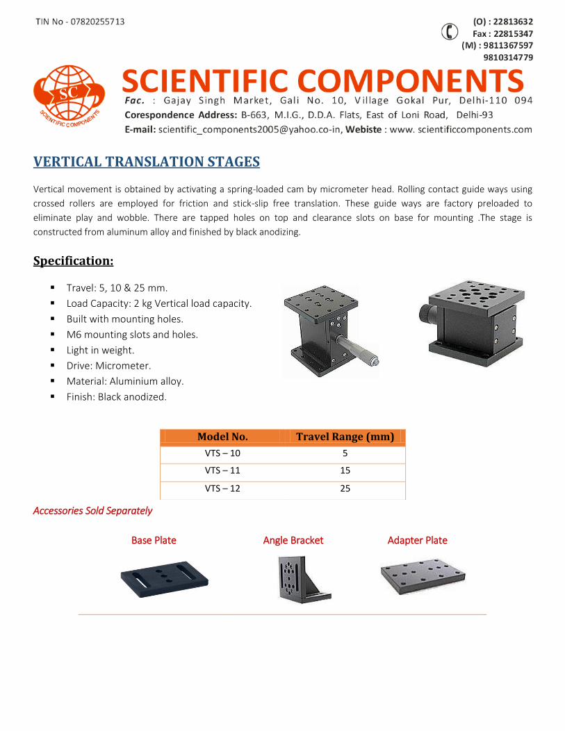
VERTICAL TRANSLATION STAGES
Vertical movement is obtained by activating a spring-loaded cam by micrometer head. Rolling contact guide ways using
crossed rollers are employed for friction and stick-slip free translation. These guide ways are factory preloaded to
eliminate play and wobble. There are tapped holes on top and clearance slots on base for mounting .The stage is
constructed from aluminum alloy and finished by black anodizing.
Specification:
Travel: 5, 10 & 25 mm.
Load Capacity: 2 kg Vertical load capacity.
Built with mounting holes.
M6 mounting slots and holes.
Light in weight.
Drive: Micrometer.
Material: Aluminium alloy.
Finish: Black anodized.
Accessories Sold Separately
Model No. Travel Range (mm)
VTS – 10 5
VTS – 11 15
VTS – 12 25
Base Plate
Angle Bracket Adapter Plate
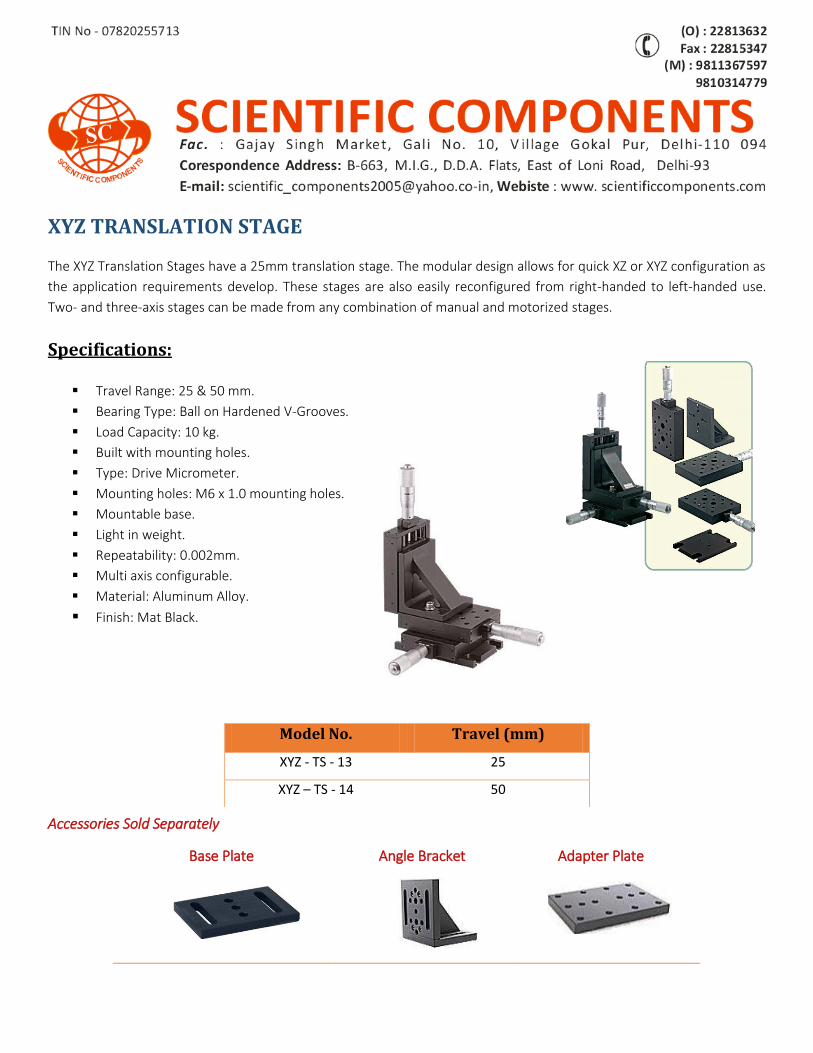
XYZ TRANSLATION STAGE
The XYZ Translation Stages have a 25mm translation stage. The modular design allows for quick XZ or XYZ configuration as
the application requirements develop. These stages are also easily reconfigured from right-handed to left-handed use.
Two- and three-axis stages can be made from any combination of manual and motorized stages.
Specifications:
Travel Range: 25 & 50 mm.
Bearing Type: Ball on Hardened V-Grooves.
Load Capacity: 10 kg.
Built with mounting holes.
Type: Drive Micrometer.
Mounting holes: M6 x 1.0 mounting holes.
Mountable base.
Light in weight.
Repeatability: 0.002mm.
Multi axis configurable.
Material: Aluminum Alloy.
Finish: Mat Black.
Accessories Sold Separately
Model No. Travel (mm)
XYZ - TS - 13 25
XYZ – TS - 14 50
Base Plate
Angle Bracket Adapter Plate
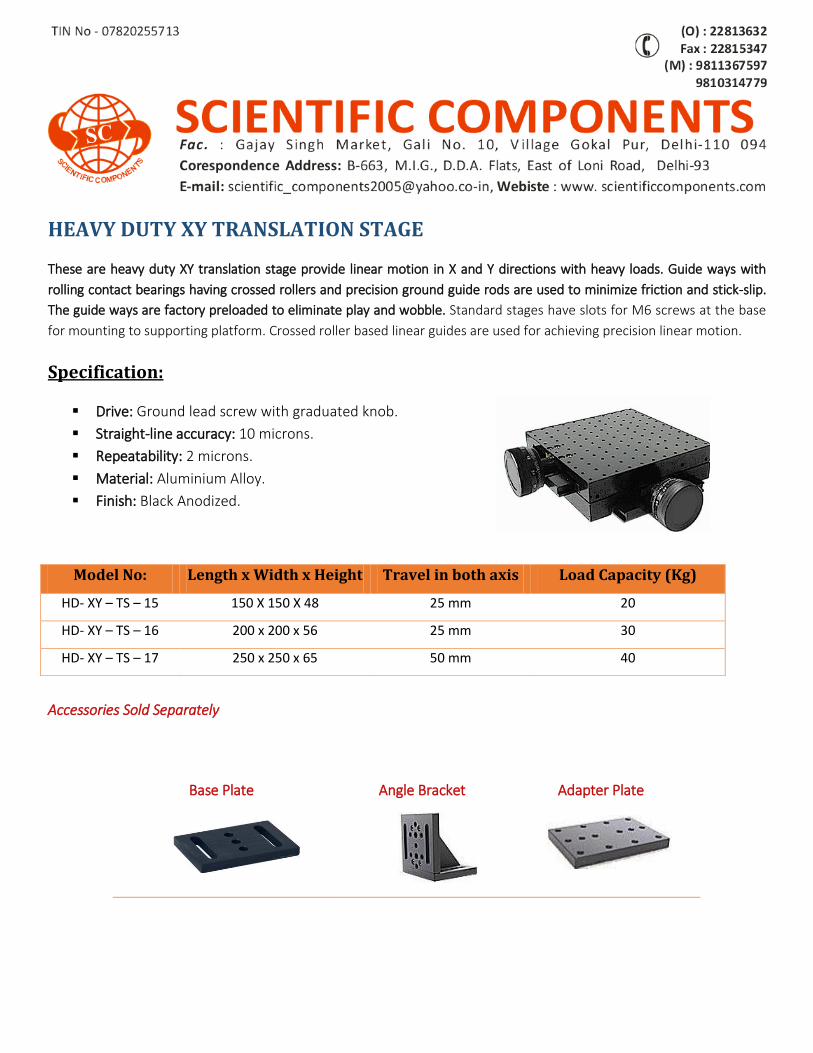
HEAVY DUTY XY TRANSLATION STAGE
These are heavy duty XY translation stage provide linear motion in X and Y directions with heavy loads. Guide ways with
rolling contact bearings having crossed rollers and precision ground guide rods are used to minimize friction and stick-slip.
The guide ways are factory preloaded to eliminate play and wobble. Standard stages have slots for M6 screws at the base
for mounting to supporting platform. Crossed roller based linear guides are used for achieving precision linear motion.
Specification:
Drive: Ground lead screw with graduated knob.
Straight-line accuracy: 10 microns.
Repeatability: 2 microns.
Material: Aluminium Alloy.
Finish: Black Anodized.
Accessories Sold Separately
Model No: Length x Width x Height Travel in both axis Load Capacity (Kg)
HD- XY – TS – 15 150 X 150 X 48 25 mm 20
HD- XY – TS – 16 200 x 200 x 56 25 mm 30
HD- XY – TS – 17 250 x 250 x 65 50 mm 40
Base Plate
Angle Bracket Adapter Plate
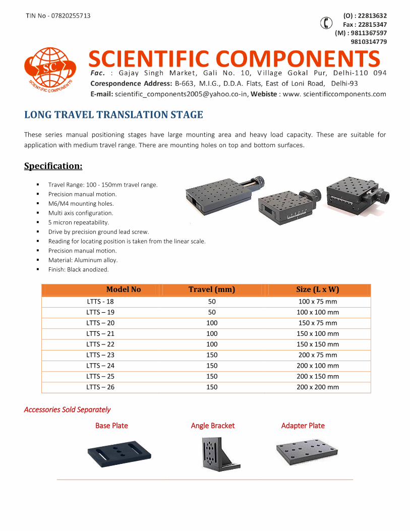
LONG TRAVEL TRANSLATION STAGE
These series manual positioning stages have large mounting area and heavy load capacity. These are suitable for
application with medium travel range. There are mounting holes on top and bottom surfaces.
Specification:
Travel Range: 100 - 150mm travel range.
Precision manual motion.
M6/M4 mounting holes.
Multi axis configuration.
5 micron repeatability.
Drive by precision ground lead screw.
Reading for locating position is taken from the linear scale.
Precision manual motion.
Material: Aluminum alloy.
Finish: Black anodized.
Model No Travel (mm) Size (L x W)
LTTS - 18 50 100 x 75 mm
LTTS – 19 50 100 x 100 mm
LTTS – 20 100 150 x 75 mm
LTTS – 21 100 150 x 100 mm
LTTS – 22 100 150 x 150 mm
LTTS – 23 150 200 x 75 mm
LTTS – 24 150 200 x 100 mm
LTTS – 25 150 200 x 150 mm
LTTS – 26 150 200 x 200 mm
Accessories Sold Separately
Base Plate
Angle Bracket Adapter Plate
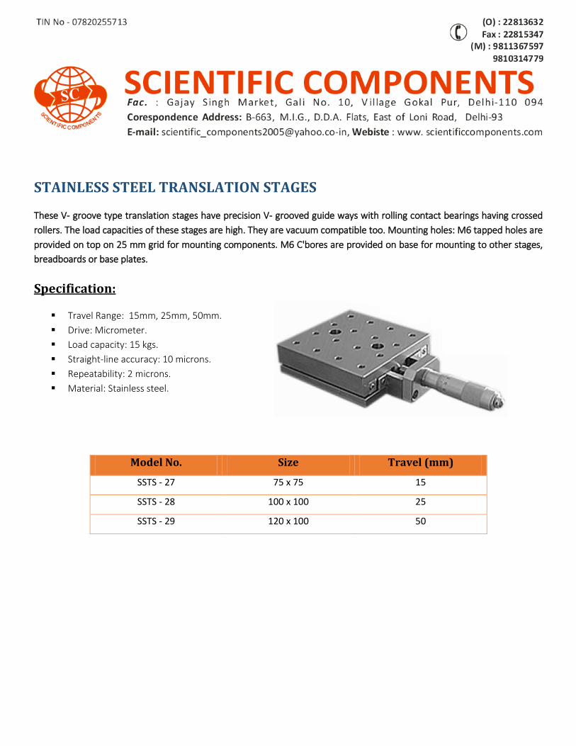
STAINLESS STEEL TRANSLATION STAGES
These V- groove type translation stages have precision V- grooved guide ways with rolling contact bearings having crossed
rollers. The load capacities of these stages are high. They are vacuum compatible too. Mounting holes: M6 tapped holes are
provided on top on 25 mm grid for mounting components. M6 C'bores are provided on base for mounting to other stages,
breadboards or base plates.
Specification:
Travel Range: 15mm, 25mm, 50mm.
Drive: Micrometer.
Load capacity: 15 kgs.
Straight-line accuracy: 10 microns.
Repeatability: 2 microns.
Material: Stainless steel.
Model No. Size Travel (mm)
SSTS - 27 75 x 75 15
SSTS - 28 100 x 100 25
SSTS - 29 120 x 100 50
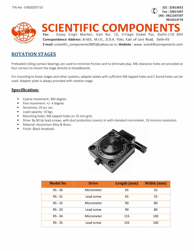
ROTATION STAGES Preloaded rolling contact bearings are used to minimize friction and to eliminate play. M6 clearance holes are provided at four corners to mount the stage directly to breadboards. For mounting to linear stages and other systems, adapter plates with sufficient M6 tapped holes and C bored holes can be used. Adapter plate is always provided with rotation stage.
Specification:
Coarse movement: 360 degree. Fine movement: +/- 4 degree. Sensitivity: 20 arc sec. Load capacity: 10 kgs. Mounting holes: M6 tapped holes on 25 mm grid. Drive: By 80 tpi lead screws, with dust protection covers/ or with standard micrometer, 10 microns resolution. Material: Aluminium Alloy & Brass. Finish: Black Anodized.
Model No Drive Length (mm) Width (mm)
RS - 30 Micrometer 65 55
RS - 31 Lead screw 65 55
RS - 32 Micrometer 90 80
RS - 33 Lead screw 90 80
RS - 34 Micrometer 115 100
RS - 35 Lead screw 155 100
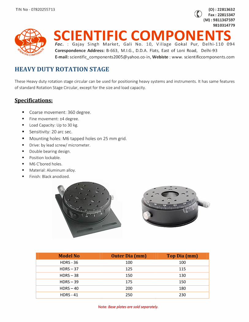
HEAVY DUTY ROTATION STAGE
These Heavy duty rotation stage circular can be used for positioning heavy systems and instruments. It has same features
of standard Rotation Stage Circular, except for the size and load capacity.
Specifications:
Coarse movement: 360 degree.
Fine movement: ±4 degree.
Load Capacity: Up to 30 kg.
Sensitivity: 20 arc sec.
Mounting holes: M6 tapped holes on 25 mm grid.
Drive: by lead screw/ micrometer.
Double bearing design.
Position lockable.
M6 C’bored holes.
Material: Aluminum alloy.
Finish: Black anodized.
Model No Outer Dia (mm) Top Dia (mm)
HDRS - 36 100 100
HDRS – 37 125 115
HDRS – 38 150 130
HDRS – 39 175 150
HDRS – 40 200 180
HDRS - 41 250 230
Note: Base plates are sold separately.
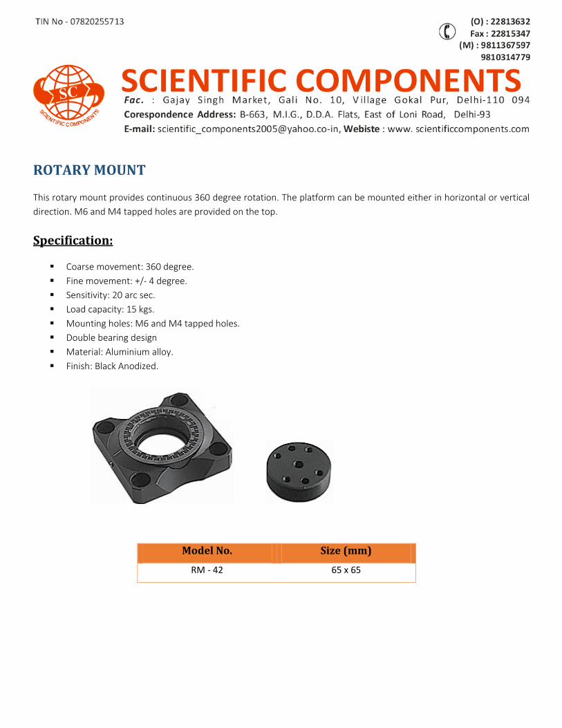
ROTARY MOUNT
This rotary mount provides continuous 360 degree rotation. The platform can be mounted either in horizontal or vertical
direction. M6 and M4 tapped holes are provided on the top.
Specification:
Coarse movement: 360 degree.
Fine movement: +/- 4 degree.
Sensitivity: 20 arc sec.
Load capacity: 15 kgs.
Mounting holes: M6 and M4 tapped holes.
Double bearing design
Material: Aluminium alloy.
Finish: Black Anodized.
Model No. Size (mm)
RM - 42 65 x 65
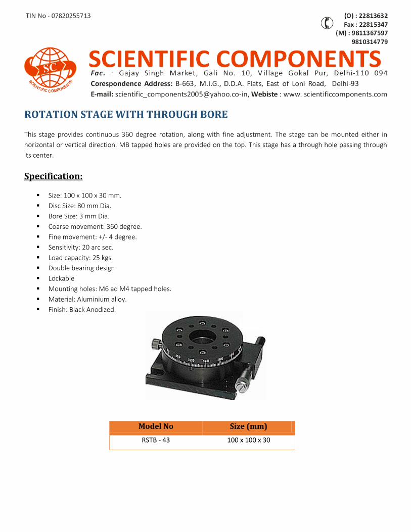
ROTATION STAGE WITH THROUGH BORE
This stage provides continuous 360 degree rotation, along with fine adjustment. The stage can be mounted either in
horizontal or vertical direction. MB tapped holes are provided on the top. This stage has a through hole passing through
its center.
Specification:
Size: 100 x 100 x 30 mm.
Disc Size: 80 mm Dia.
Bore Size: 3 mm Dia.
Coarse movement: 360 degree.
Fine movement: +/- 4 degree.
Sensitivity: 20 arc sec.
Load capacity: 25 kgs.
Double bearing design
Lockable
Mounting holes: M6 ad M4 tapped holes.
Material: Aluminium alloy.
Finish: Black Anodized.
Model No Size (mm)
RSTB - 43 100 x 100 x 30
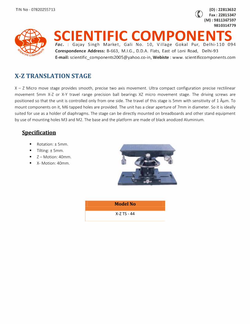
X-Z TRANSLATION STAGE
X – Z Micro move stage provides smooth, precise two axis movement. Ultra compact configuration precise rectilinear
movement 5mm X-Z or X-Y travel range precision ball bearings XZ micro movement stage. The driving screws are
positioned so that the unit is controlled only from one side. The travel of this stage is 5mm with sensitivity of 1 µm. To
mount components on it, M6 tapped holes are provided. The unit has a clear aperture of 7mm in diameter. So it is ideally
suited for use as a holder of diaphragms. The stage can be directly mounted on breadboards and other stand equipment
by use of mounting holes M3 and M2. The base and the platform are made of black anodized Aluminium.
Specification
Rotation: ± 5mm.
Tilting: ± 5mm.
Z – Motion: 40mm.
X- Motion: 40mm.
Model No
X-Z TS - 44
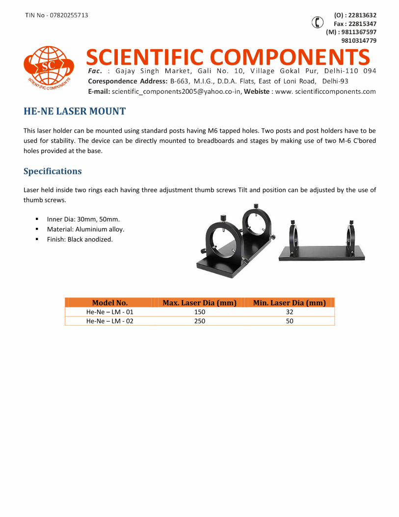
HE-NE LASER MOUNT
This laser holder can be mounted using standard posts having M6 tapped holes. Two posts and post holders have to be
used for stability. The device can be directly mounted to breadboards and stages by making use of two M-6 C'bored
holes provided at the base.
Specifications
Laser held inside two rings each having three adjustment thumb screws Tilt and position can be adjusted by the use of
thumb screws.
Inner Dia: 30mm, 50mm.
Material: Aluminium alloy.
Finish: Black anodized.
Model No. Max. Laser Dia (mm) Min. Laser Dia (mm) He-Ne – LM - 01 150 32
He-Ne – LM - 02 250 50
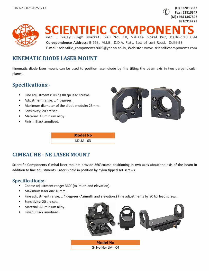
KINEMATIC DIODE LASER MOUNT
Kinematic diode laser mount can be used to position laser diode by fine tilting the beam axis in two perpendicular
planes.
Specifications:-
Fine adjustments: Using 80 tpi lead screws.
Adjustment range: ± 4 degrees.
Maximum diameter of the diode module: 25mm.
Sensitivity: 20 arc sec.
Material: Aluminium alloy.
Finish: Black anodized.
GIMBAL HE - NE LASER MOUNT
Scientific Components Gimbal laser mounts provide 360°coarse positioning in two axes about the axis of the beam in
addition to fine adjustments. Laser is held in position by nylon tipped set-screws.
Specifications:- Coarse adjustment range: 360° (Azimuth and elevation).
Maximum laser dia: 40mm.
Fine adjustment range: ± 4 degrees (Azimuth and elevation.) Fine adjustments by 80 tpi lead screws.
Sensitivity: 20 arc sec.
Material: Aluminium alloy.
Finish: Black anodized.
Model No
G- He-Ne- LM - 04
Model No
KDLM - 03
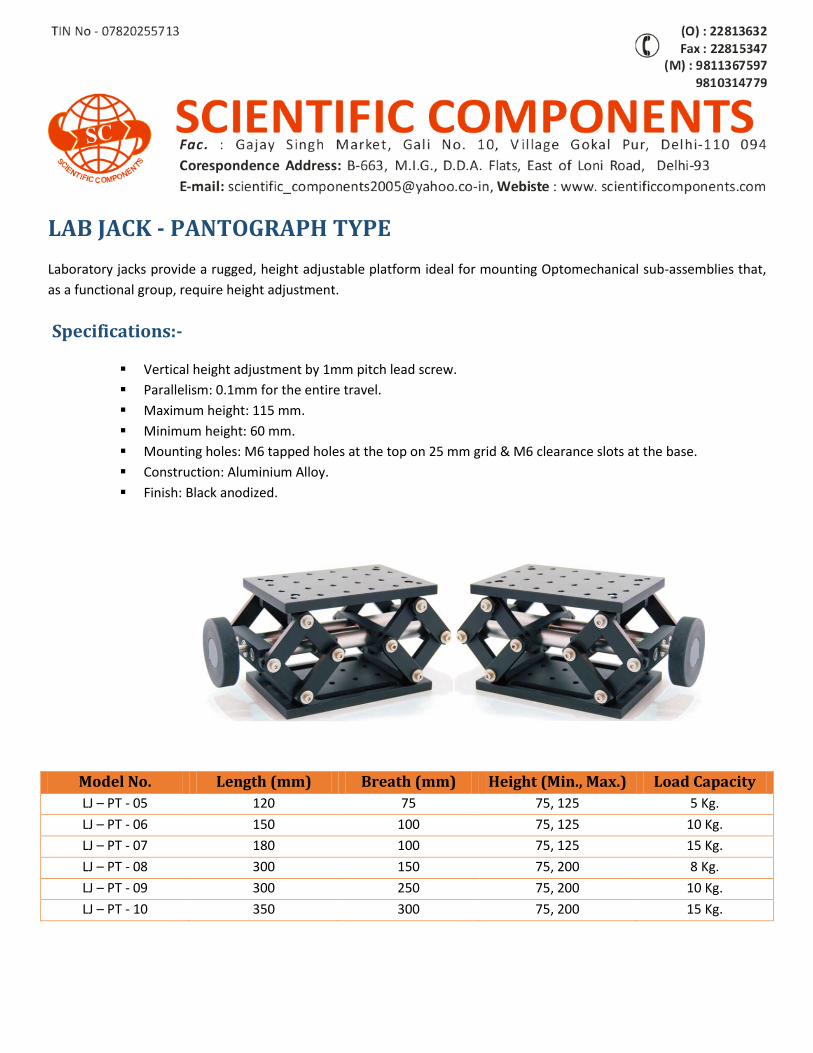
LAB JACK - PANTOGRAPH TYPE
Laboratory jacks provide a rugged, height adjustable platform ideal for mounting Optomechanical sub-assemblies that,
as a functional group, require height adjustment.
Specifications:-
Vertical height adjustment by 1mm pitch lead screw.
Parallelism: 0.1mm for the entire travel.
Maximum height: 115 mm.
Minimum height: 60 mm.
Mounting holes: M6 tapped holes at the top on 25 mm grid & M6 clearance slots at the base.
Construction: Aluminium Alloy.
Finish: Black anodized.
Model No. Length (mm) Breath (mm) Height (Min., Max.) Load Capacity
LJ – PT - 05 120 75 75, 125 5 Kg.
LJ – PT - 06 150 100 75, 125 10 Kg.
LJ – PT - 07 180 100 75, 125 15 Kg.
LJ – PT - 08 300 150 75, 200 8 Kg.
LJ – PT - 09 300 250 75, 200 10 Kg.
LJ – PT - 10 350 300 75, 200 15 Kg.
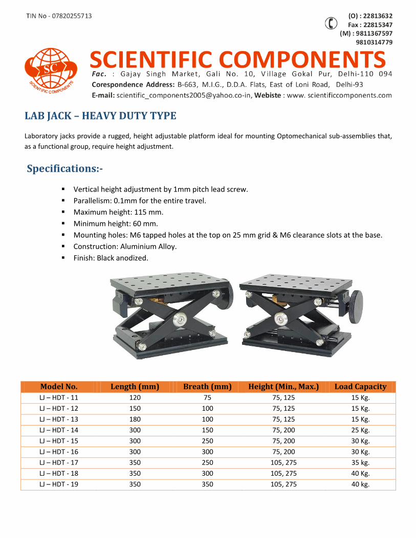
LAB JACK – HEAVY DUTY TYPE
Laboratory jacks provide a rugged, height adjustable platform ideal for mounting Optomechanical sub-assemblies that,
as a functional group, require height adjustment.
Specifications:-
Vertical height adjustment by 1mm pitch lead screw.
Parallelism: 0.1mm for the entire travel.
Maximum height: 115 mm.
Minimum height: 60 mm.
Mounting holes: M6 tapped holes at the top on 25 mm grid & M6 clearance slots at the base.
Construction: Aluminium Alloy.
Finish: Black anodized.
Model No. Length (mm) Breath (mm) Height (Min., Max.) Load Capacity
LJ – HDT - 11 120 75 75, 125 15 Kg.
LJ – HDT - 12 150 100 75, 125 15 Kg.
LJ – HDT - 13 180 100 75, 125 15 Kg.
LJ – HDT - 14 300 150 75, 200 25 Kg.
LJ – HDT - 15 300 250 75, 200 30 Kg.
LJ – HDT - 16 300 300 75, 200 30 Kg.
LJ – HDT - 17 350 250 105, 275 35 kg.
LJ – HDT - 18 350 300 105, 275 40 Kg.
LJ – HDT - 19 350 350 105, 275 40 kg.
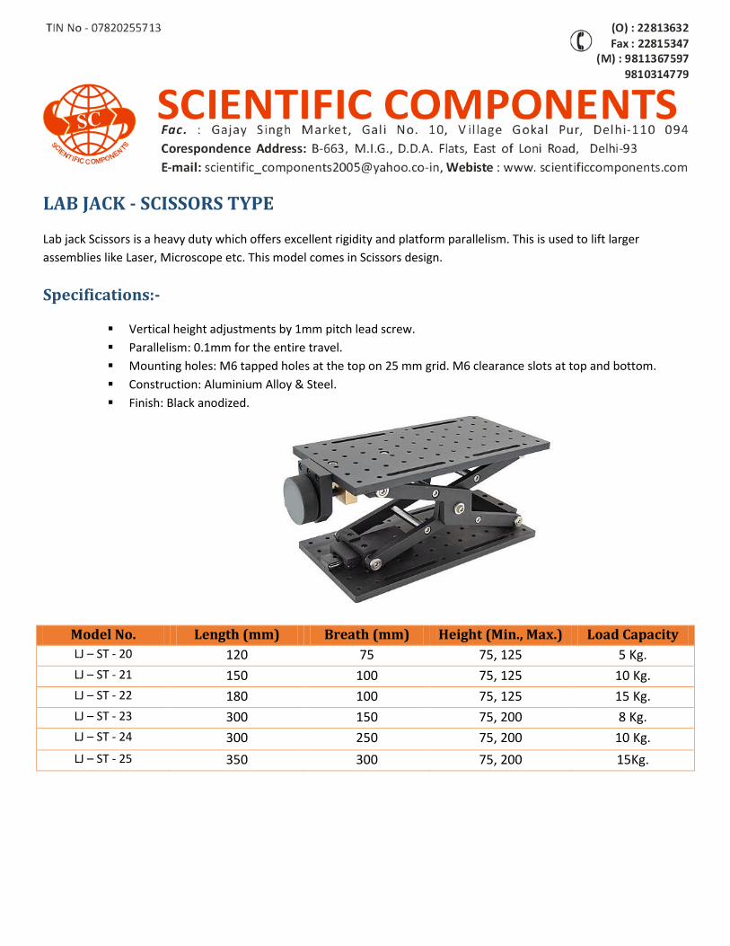
LAB JACK - SCISSORS TYPE
Lab jack Scissors is a heavy duty which offers excellent rigidity and platform parallelism. This is used to lift larger
assemblies like Laser, Microscope etc. This model comes in Scissors design.
Specifications:-
Vertical height adjustments by 1mm pitch lead screw.
Parallelism: 0.1mm for the entire travel.
Mounting holes: M6 tapped holes at the top on 25 mm grid. M6 clearance slots at top and bottom.
Construction: Aluminium Alloy & Steel.
Finish: Black anodized.
Model No. Length (mm) Breath (mm) Height (Min., Max.) Load Capacity
LJ – ST - 20 120 75 75, 125 5 Kg.
LJ – ST - 21 150 100 75, 125 10 Kg.
LJ – ST - 22 180 100 75, 125 15 Kg.
LJ – ST - 23 300 150 75, 200 8 Kg.
LJ – ST - 24 300 250 75, 200 10 Kg.
LJ – ST - 25 350 300 75, 200 15Kg.
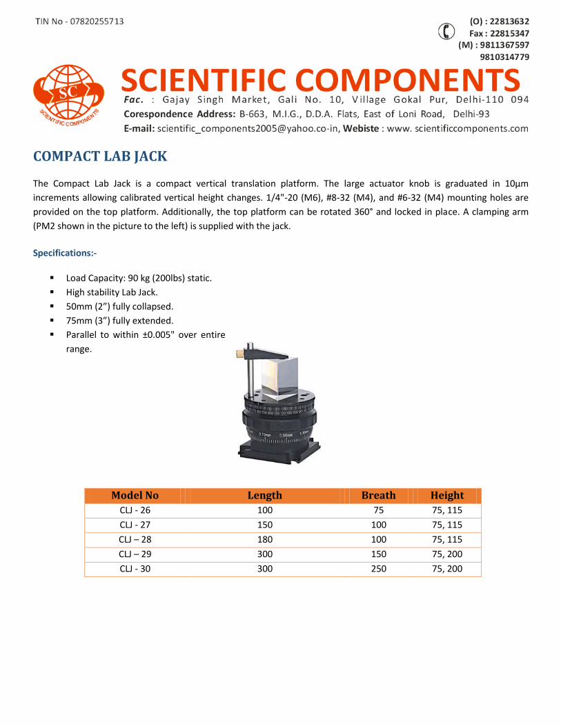
COMPACT LAB JACK
The Compact Lab Jack is a compact vertical translation platform. The large actuator knob is graduated in 10µm
increments allowing calibrated vertical height changes. 1/4"-20 (M6), #8-32 (M4), and #6-32 (M4) mounting holes are
provided on the top platform. Additionally, the top platform can be rotated 360° and locked in place. A clamping arm
(PM2 shown in the picture to the left) is supplied with the jack.
Specifications:-
Load Capacity: 90 kg (200lbs) static.
High stability Lab Jack.
50mm (2”) fully collapsed.
75mm (3”) fully extended.
Parallel to within ±0.005" over entire
range.
Model No Length Breath Height
CLJ - 26 100 75 75, 115
CLJ - 27 150 100 75, 115
CLJ – 28 180 100 75, 115
CLJ – 29 300 150 75, 200
CLJ - 30 300 250 75, 200
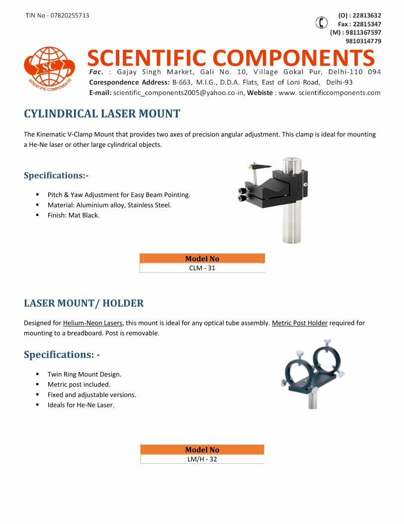
CYLINDRICAL LASER MOUNT The Kinematic V-Clamp Mount that provides two axes of precision angular adjustment. This clamp is ideal for mounting
a He-Ne laser or other large cylindrical objects.
Specifications:-
Pitch & Yaw Adjustment for Easy Beam Pointing.
Material: Aluminium alloy, Stainless Steel.
Finish: Mat Black.
LASER MOUNT/ HOLDER
Designed for Helium-Neon Lasers, this mount is ideal for any optical tube assembly. Metric Post Holder required for
mounting to a breadboard. Post is removable.
Specifications: -
Twin Ring Mount Design.
Metric post included.
Fixed and adjustable versions.
Ideals for He-Ne Laser.
Model No CLM - 31
Model No LM/H - 32
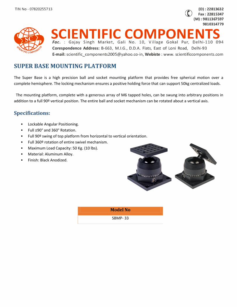
SUPER BASE MOUNTING PLATFORM
The Super Base is a high precision ball and socket mounting platform that provides free spherical motion over a
complete hemisphere. The locking mechanism ensures a positive holding force that can support 50kg centralized loads.
The mounting platform, complete with a generous array of M6 tapped holes, can be swung into arbitrary positions in
addition to a full 90º vertical position. The entire ball and socket mechanism can be rotated about a vertical axis.
Specifications:
Lockable Angular Positioning.
Full ±90° and 360° Rotation.
Full 90º swing of top platform from horizontal to vertical orientation.
Full 360º rotation of entire swivel mechanism.
Maximum Load Capacity: 50 Kg. (10 lbs).
Material: Aluminum Alloy.
Finish: Black Anodized.
Model No
SBMP- 33
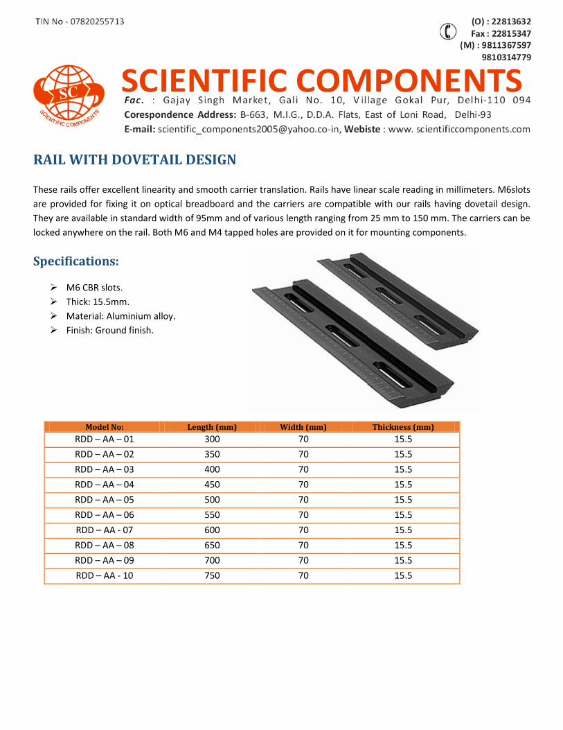
RAIL WITH DOVETAIL DESIGN
These rails offer excellent linearity and smooth carrier translation. Rails have linear scale reading in millimeters. M6slots
are provided for fixing it on optical breadboard and the carriers are compatible with our rails having dovetail design.
They are available in standard width of 95mm and of various length ranging from 25 mm to 150 mm. The carriers can be
locked anywhere on the rail. Both M6 and M4 tapped holes are provided on it for mounting components.
Specifications:
M6 CBR slots.
Thick: 15.5mm.
Material: Aluminium alloy.
Finish: Ground finish.
Model No: Length (mm) Width (mm) Thickness (mm) RDD – AA – 01 300 70 15.5
RDD – AA – 02 350 70 15.5
RDD – AA – 03 400 70 15.5
RDD – AA – 04 450 70 15.5
RDD – AA – 05 500 70 15.5
RDD – AA – 06 550 70 15.5
RDD – AA - 07 600 70 15.5
RDD – AA – 08 650 70 15.5
RDD – AA – 09 700 70 15.5
RDD – AA - 10 750 70 15.5
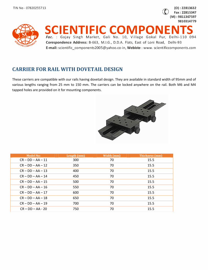
CARRIER FOR RAIL WITH DOVETAIL DESIGN
These carriers are compatible with our rails having dovetail design. They are available in standard width of 95mm and of
various lengths ranging from 25 mm to 150 mm. The carriers can be locked anywhere on the rail. Both M6 and M4
tapped holes are provided on it for mounting components.
Model No: Length (mm) Width (mm) Thickness (mm) CR – DD – AA – 11 300 70 15.5
CR – DD – AA – 12 350 70 15.5
CR – DD – AA – 13 400 70 15.5
CR – DD – AA – 14 450 70 15.5
CR – DD – AA – 15 500 70 15.5
CR – DD – AA – 16 550 70 15.5
CR – DD – AA – 17 600 70 15.5
CR – DD – AA – 18 650 70 15.5
CR – DD – AA – 19 700 70 15.5
CR – DD – AA - 20 750 70 15.5
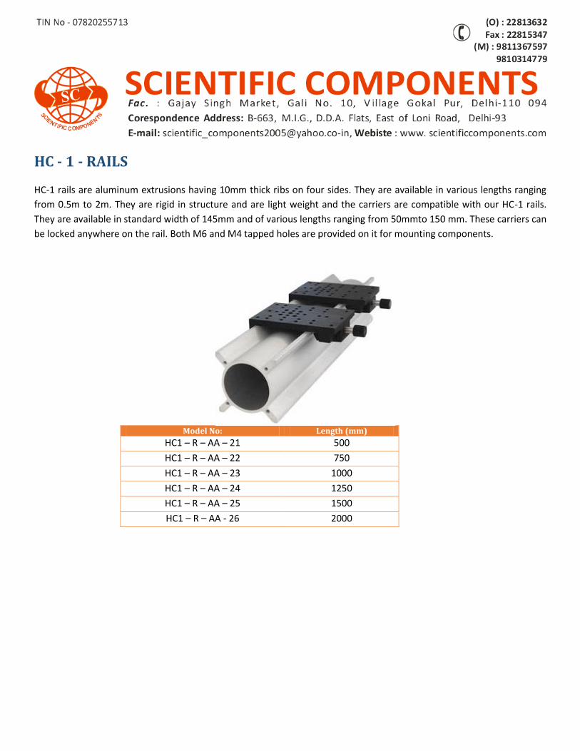
HC - 1 - RAILS
HC-1 rails are aluminum extrusions having 10mm thick ribs on four sides. They are available in various lengths ranging
from 0.5m to 2m. They are rigid in structure and are light weight and the carriers are compatible with our HC-1 rails.
They are available in standard width of 145mm and of various lengths ranging from 50mmto 150 mm. These carriers can
be locked anywhere on the rail. Both M6 and M4 tapped holes are provided on it for mounting components.
Model No: Length (mm)
HC1 – R – AA – 21 500
HC1 – R – AA – 22 750
HC1 – R – AA – 23 1000
HC1 – R – AA – 24 1250
HC1 – R – AA – 25 1500
HC1 – R – AA - 26 2000
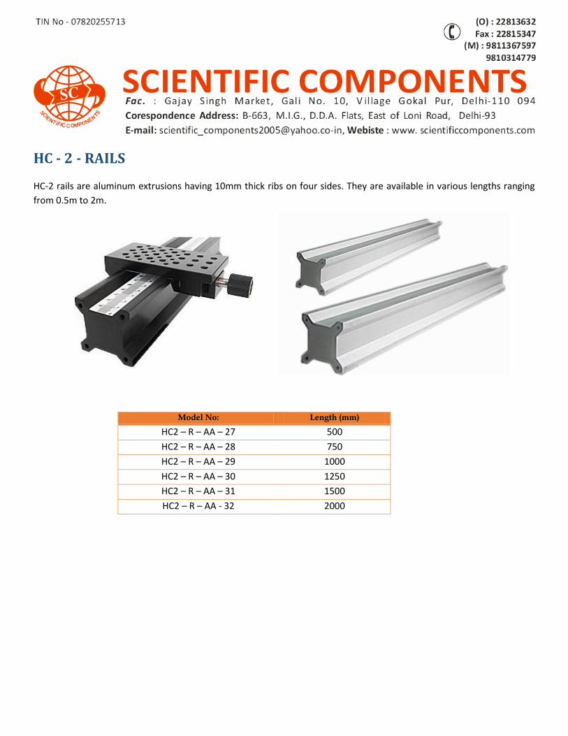
HC - 2 - RAILS
HC-2 rails are aluminum extrusions having 10mm thick ribs on four sides. They are available in various lengths ranging
from 0.5m to 2m.
Model No: Length (mm)
HC2 – R – AA – 27 500
HC2 – R – AA – 28 750
HC2 – R – AA – 29 1000
HC2 – R – AA – 30 1250
HC2 – R – AA – 31 1500
HC2 – R – AA - 32 2000

CARRIERS FOR HC - 1 - RAIL
These carriers are compatible with our HC-1 rails. They are available in standard width of 145mm and of various lengths
ranging from 50 mm to 150 mm. These carriers can be locked anywhere on the rail. Both M6 and M4 tapped holes are
provided on it for mounting components.
Model No: Length (mm) Width (mm)
C - HC1- R – AA – 33 150 145
C - HC1- R – AA – 34 125 145
C - HC1- R – AA - 35 100 145
C - HC1- R – AA – 36 75 145
C - HC1- R – AA - 37 50 145
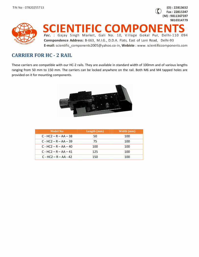
CARRIER FOR HC - 2 RAIL
These carriers are compatible with our HC-2 rails. They are available in standard width of 100mm and of various lengths
ranging from 50 mm to 150 mm. The carriers can be locked anywhere on the rail. Both M6 and M4 tapped holes are
provided on it for mounting components.
Model No: Length (mm) Width (mm)
C - HC2 – R – AA – 38 50 100
C - HC2 – R – AA – 39 75 100
C - HC2 – R – AA – 40 100 100
C - HC2 – R – AA – 41 125 100
C - HC2 – R – AA - 42 150 100
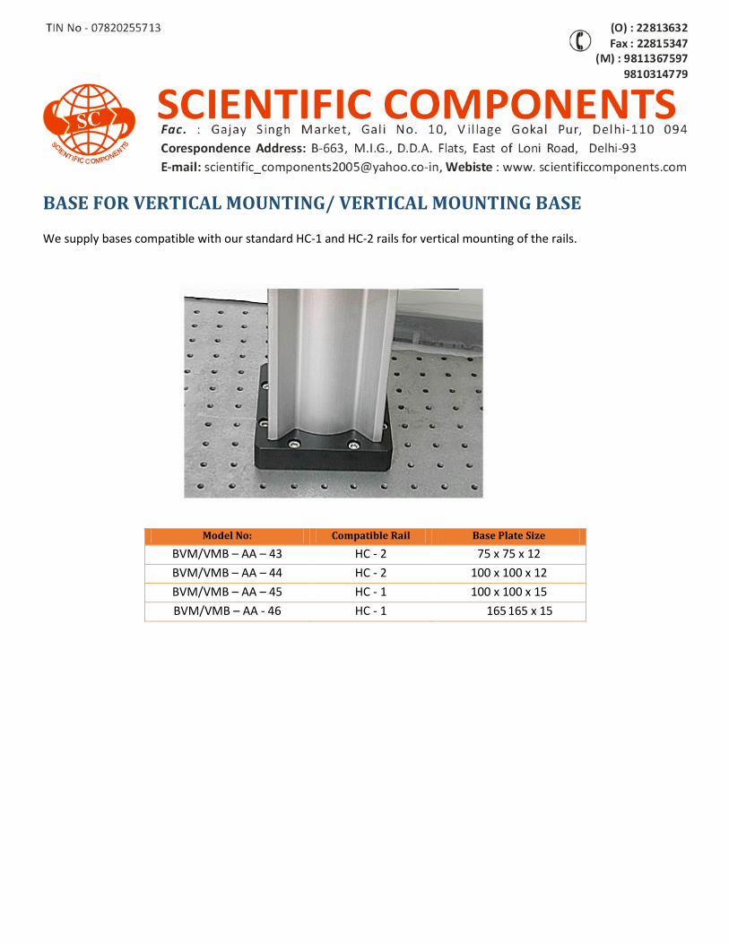
BASE FOR VERTICAL MOUNTING/ VERTICAL MOUNTING BASE
We supply bases compatible with our standard HC-1 and HC-2 rails for vertical mounting of the rails.
Model No: Compatible Rail Base Plate Size
BVM/VMB – AA – 43 HC - 2 75 x 75 x 12
BVM/VMB – AA – 44 HC - 2 100 x 100 x 12
BVM/VMB – AA – 45 HC - 1 100 x 100 x 15
BVM/VMB – AA - 46 HC - 1 165 165 x 15
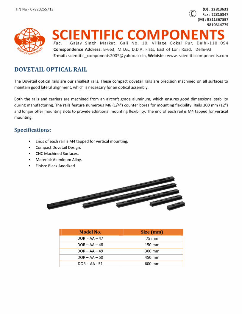
DOVETAIL OPTICAL RAIL
The Dovetail optical rails are our smallest rails. These compact dovetail rails are precision machined on all surfaces to
maintain good lateral alignment, which is necessary for an optical assembly.
Both the rails and carriers are machined from an aircraft grade aluminum, which ensures good dimensional stability
during manufacturing. The rails feature numerous M6 (1/4") counter bores for mounting flexibility. Rails 300 mm (12")
and longer offer mounting slots to provide additional mounting flexibility. The end of each rail is M4 tapped for vertical
mounting.
Specifications:
Ends of each rail is M4 tapped for vertical mounting.
Compact Dovetail Design.
CNC Machined Surfaces.
Material: Aluminum Alloy.
Finish: Black Anodized.
Model No. Size (mm)
DOR - AA – 47 75 mm
DOR – AA – 48 150 mm
DOR – AA – 49 300 mm
DOR – AA – 50 450 mm
DOR - AA - 51 600 mm
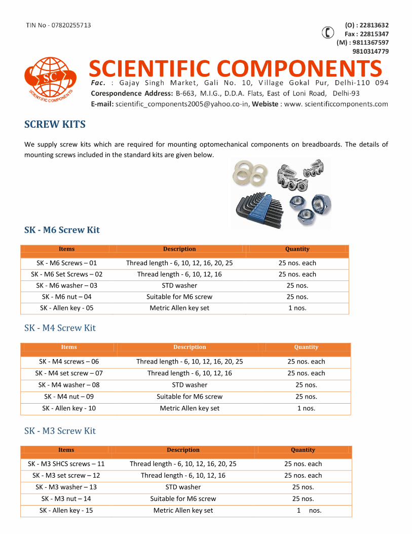
SCREW KITS
We supply screw kits which are required for mounting optomechanical components on breadboards. The details of
mounting screws included in the standard kits are given below.
SK - M6 Screw Kit
Items Description Quantity
SK - M6 Screws – 01 Thread length - 6, 10, 12, 16, 20, 25 25 nos. each
SK - M6 Set Screws – 02 Thread length - 6, 10, 12, 16 25 nos. each
SK - M6 washer – 03 STD washer 25 nos.
SK - M6 nut – 04 Suitable for M6 screw 25 nos.
SK - Allen key - 05 Metric Allen key set 1 nos.
SK - M4 Screw Kit
Items Description Quantity
SK - M4 screws – 06 Thread length - 6, 10, 12, 16, 20, 25 25 nos. each
SK - M4 set screw – 07 Thread length - 6, 10, 12, 16 25 nos. each
SK - M4 washer – 08 STD washer 25 nos.
SK - M4 nut – 09 Suitable for M6 screw 25 nos.
SK - Allen key - 10 Metric Allen key set 1 nos.
SK - M3 Screw Kit
Items Description Quantity
SK - M3 SHCS screws – 11 Thread length - 6, 10, 12, 16, 20, 25 25 nos. each
SK - M3 set screw – 12 Thread length - 6, 10, 12, 16 25 nos. each
SK - M3 washer – 13 STD washer 25 nos.
SK - M3 nut – 14 Suitable for M6 screw 25 nos.
SK - Allen key - 15 Metric Allen key set 1 nos.
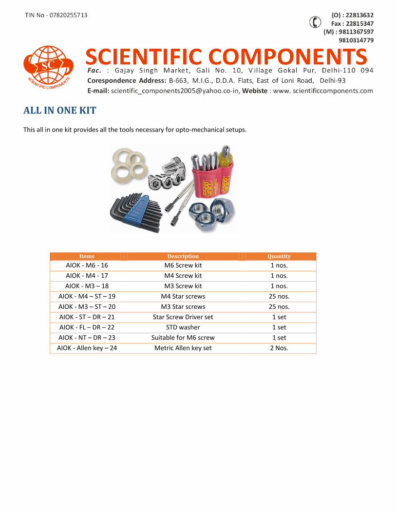
ALL IN ONE KIT
This all in one kit provides all the tools necessary for opto-mechanical setups.
Items Description Quantity AIOK - M6 - 16 M6 Screw kit 1 nos.
AIOK - M4 - 17 M4 Screw kit 1 nos.
AIOK - M3 – 18 M3 Screw kit 1 nos.
AIOK - M4 – ST – 19 M4 Star screws 25 nos.
AIOK - M3 – ST – 20 M3 Star screws 25 nos.
AIOK - ST – DR – 21 Star Screw Driver set 1 set
AIOK - FL – DR – 22 STD washer 1 set
AIOK - NT – DR – 23 Suitable for M6 screw 1 set
AIOK - Allen key – 24 Metric Allen key set 2 Nos.
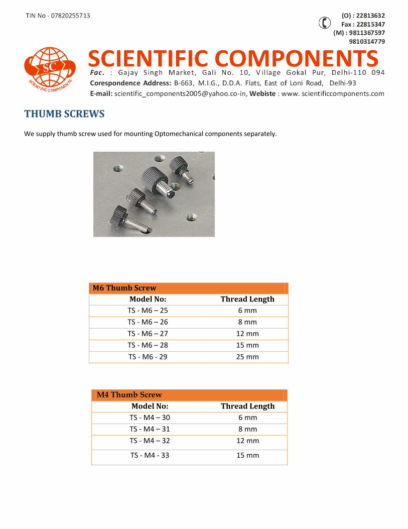
THUMB SCREWS
We supply thumb screw used for mounting Optomechanical components separately.
M6 Thumb Screw
Model No: Thread Length
TS - M6 – 25 6 mm
TS - M6 – 26 8 mm
TS - M6 – 27 12 mm
TS - M6 – 28 15 mm
TS - M6 - 29 25 mm
M4 Thumb Screw
Model No: Thread Length
TS - M4 – 30 6 mm
TS - M4 – 31 8 mm
TS - M4 – 32 12 mm
TS - M4 - 33 15 mm
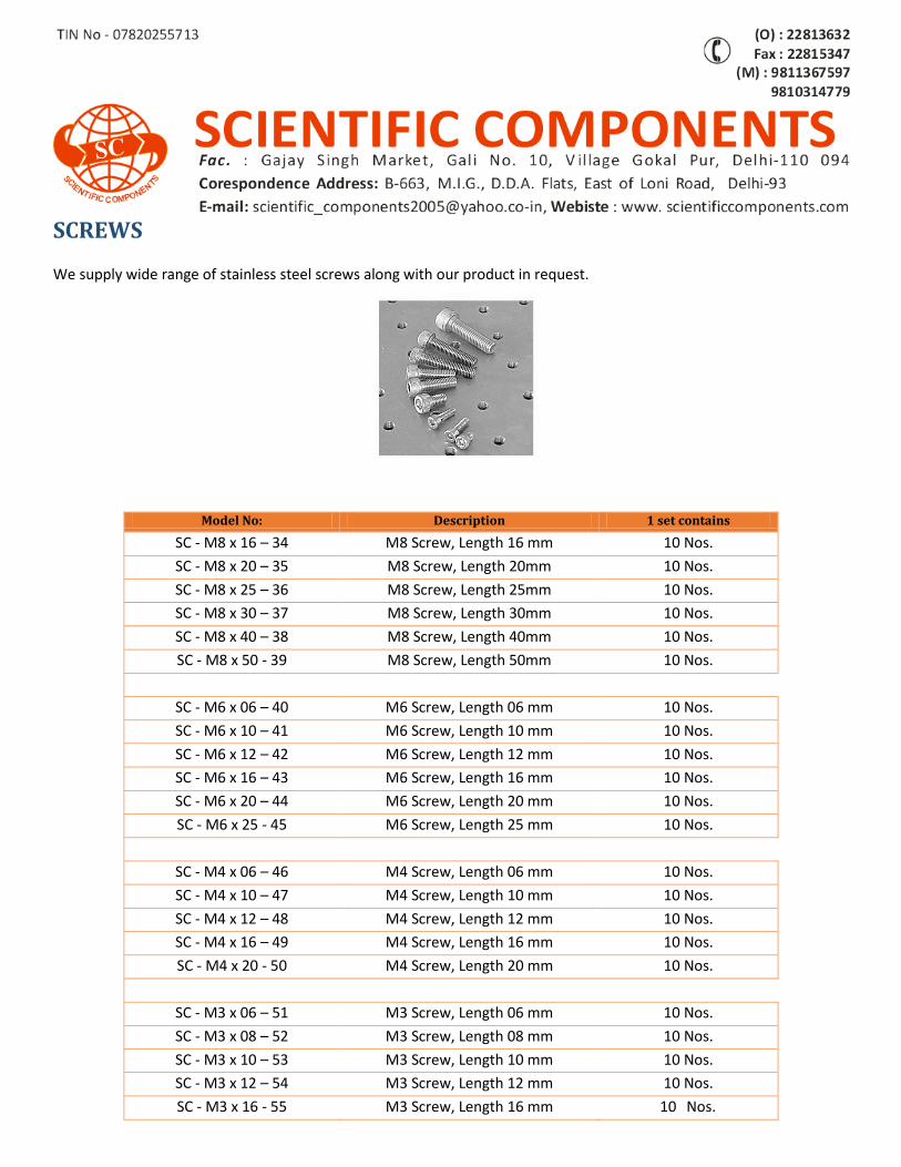
SCREWS
We supply wide range of stainless steel screws along with our product in request.
Model No: Description 1 set contains
SC - M8 x 16 – 34 M8 Screw, Length 16 mm 10 Nos.
SC - M8 x 20 – 35 M8 Screw, Length 20mm 10 Nos.
SC - M8 x 25 – 36 M8 Screw, Length 25mm 10 Nos.
SC - M8 x 30 – 37 M8 Screw, Length 30mm 10 Nos.
SC - M8 x 40 – 38 M8 Screw, Length 40mm 10 Nos.
SC - M8 x 50 - 39 M8 Screw, Length 50mm 10 Nos.
SC - M6 x 06 – 40 M6 Screw, Length 06 mm 10 Nos.
SC - M6 x 10 – 41 M6 Screw, Length 10 mm 10 Nos.
SC - M6 x 12 – 42 M6 Screw, Length 12 mm 10 Nos.
SC - M6 x 16 – 43 M6 Screw, Length 16 mm 10 Nos.
SC - M6 x 20 – 44 M6 Screw, Length 20 mm 10 Nos.
SC - M6 x 25 - 45 M6 Screw, Length 25 mm 10 Nos.
SC - M4 x 06 – 46 M4 Screw, Length 06 mm 10 Nos.
SC - M4 x 10 – 47 M4 Screw, Length 10 mm 10 Nos.
SC - M4 x 12 – 48 M4 Screw, Length 12 mm 10 Nos.
SC - M4 x 16 – 49 M4 Screw, Length 16 mm 10 Nos.
SC - M4 x 20 - 50 M4 Screw, Length 20 mm 10 Nos.
SC - M3 x 06 – 51 M3 Screw, Length 06 mm 10 Nos.
SC - M3 x 08 – 52 M3 Screw, Length 08 mm 10 Nos.
SC - M3 x 10 – 53 M3 Screw, Length 10 mm 10 Nos.
SC - M3 x 12 – 54 M3 Screw, Length 12 mm 10 Nos.
SC - M3 x 16 - 55 M3 Screw, Length 16 mm 10 Nos.
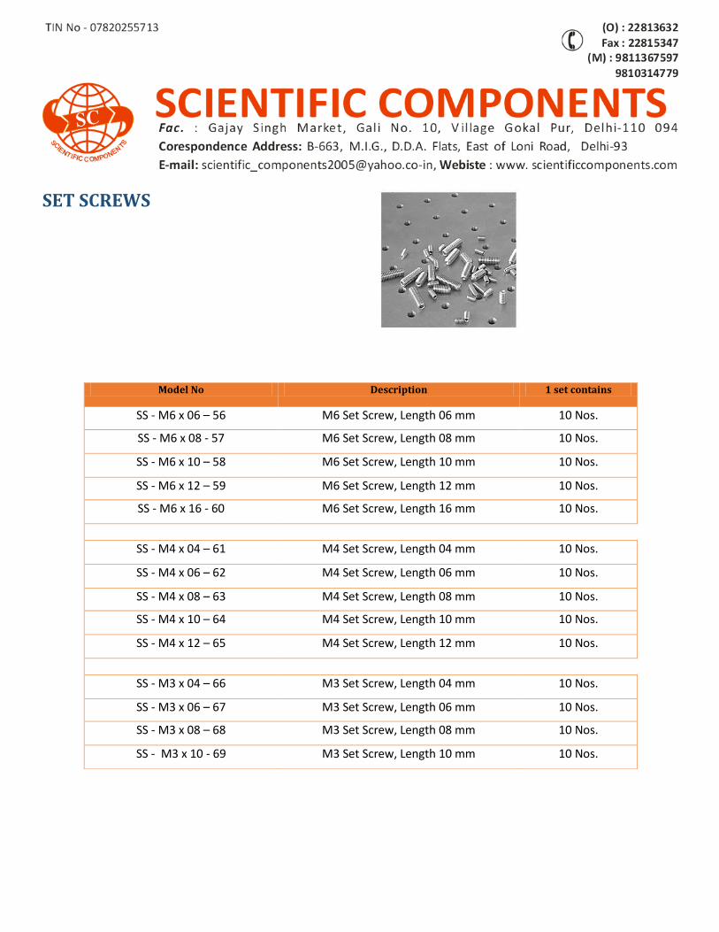
SET SCREWS
Model No Description 1 set contains
SS - M6 x 06 – 56 M6 Set Screw, Length 06 mm 10 Nos.
SS - M6 x 08 - 57 M6 Set Screw, Length 08 mm 10 Nos.
SS - M6 x 10 – 58 M6 Set Screw, Length 10 mm 10 Nos.
SS - M6 x 12 – 59 M6 Set Screw, Length 12 mm 10 Nos.
SS - M6 x 16 - 60 M6 Set Screw, Length 16 mm 10 Nos.
SS - M4 x 04 – 61 M4 Set Screw, Length 04 mm 10 Nos.
SS - M4 x 06 – 62 M4 Set Screw, Length 06 mm 10 Nos.
SS - M4 x 08 – 63 M4 Set Screw, Length 08 mm 10 Nos.
SS - M4 x 10 – 64 M4 Set Screw, Length 10 mm 10 Nos.
SS - M4 x 12 – 65 M4 Set Screw, Length 12 mm 10 Nos.
SS - M3 x 04 – 66 M3 Set Screw, Length 04 mm 10 Nos.
SS - M3 x 06 – 67 M3 Set Screw, Length 06 mm 10 Nos.
SS - M3 x 08 – 68 M3 Set Screw, Length 08 mm 10 Nos.
SS - M3 x 10 - 69 M3 Set Screw, Length 10 mm 10 Nos.
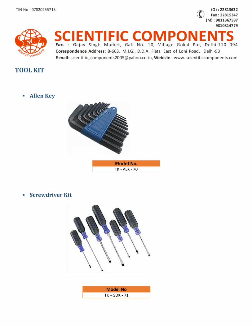
TOOL KIT
Allen Key
Screwdriver Kit
Model No TK – SDK - 71
Model No. TK - ALK - 70
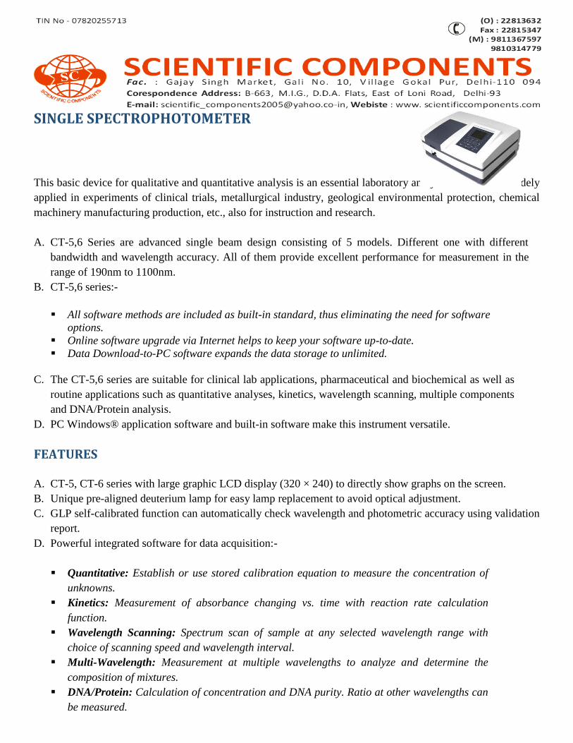
SINGLE SPECTROPHOTOMETER
This basic device for qualitative and quantitative analysis is an essential laboratory analytical instrument widely
applied in experiments of clinical trials, metallurgical industry, geological environmental protection, chemical
machinery manufacturing production, etc., also for instruction and research.
A. CT-5,6 Series are advanced single beam design consisting of 5 models. Different one with different
bandwidth and wavelength accuracy. All of them provide excellent performance for measurement in the
range of 190nm to 1100nm.
B. CT-5,6 series:-
All software methods are included as built-in standard, thus eliminating the need for software
options.
Online software upgrade via Internet helps to keep your software up-to-date.
Data Download-to-PC software expands the data storage to unlimited.
C. The CT-5,6 series are suitable for clinical lab applications, pharmaceutical and biochemical as well as
routine applications such as quantitative analyses, kinetics, wavelength scanning, multiple components
and DNA/Protein analysis.
D. PC Windows® application software and built-in software make this instrument versatile.
FEATURES A. CT-5, CT-6 series with large graphic LCD display (320 × 240) to directly show graphs on the screen.
B. Unique pre-aligned deuterium lamp for easy lamp replacement to avoid optical adjustment.
C. GLP self-calibrated function can automatically check wavelength and photometric accuracy using validation
report.
D. Powerful integrated software for data acquisition:-
Quantitative: Establish or use stored calibration equation to measure the concentration of
unknowns.
Kinetics: Measurement of absorbance changing vs. time with reaction rate calculation
function.
Wavelength Scanning: Spectrum scan of sample at any selected wavelength range with
choice of scanning speed and wavelength interval.
Multi-Wavelength: Measurement at multiple wavelengths to analyze and determine the
composition of mixtures.
DNA/Protein: Calculation of concentration and DNA purity. Ratio at other wavelengths can
be measured.
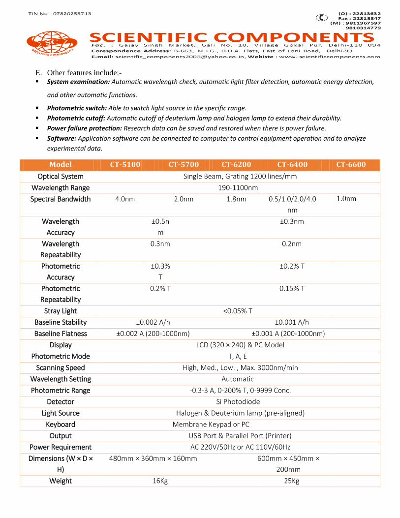
E. Other features include:- System examination: Automatic wavelength check, automatic light filter detection, automatic energy detection,
and other automatic functions.
Photometric switch: Able to switch light source in the specific range.
Photometric cutoff: Automatic cutoff of deuterium lamp and halogen lamp to extend their durability.
Power failure protection: Research data can be saved and restored when there is power failure.
Software: Application software can be connected to computer to control equipment operation and to analyze
experimental data.
Model CT-5100 CT-5700 CT-6200 CT-6400 CT-6600
Optical System Single Beam, Grating 1200 lines/mm
Wavelength Range 190-1100nm
Spectral Bandwidth 4.0nm 2.0nm 1.8nm 0.5/1.0/2.0/4.0
nm
1.0nm
Wavelength
Accuracy
±0.5n
m
±0.3nm
Wavelength
Repeatability
0.3nm 0.2nm
Photometric
Accuracy
±0.3%
T
±0.2% T
Photometric
Repeatability
0.2% T 0.15% T
Stray Light <0.05% T
Baseline Stability ±0.002 A/h ±0.001 A/h
Baseline Flatness ±0.002 A (200-1000nm) ±0.001 A (200-1000nm)
Display LCD (320 × 240) & PC Model
Photometric Mode T, A, E
Scanning Speed High, Med., Low. , Max. 3000nm/min
Wavelength Setting Automatic
Photometric Range -0.3-3 A, 0-200% T, 0-9999 Conc.
Detector Si Photodiode
Light Source Halogen & Deuterium lamp (pre-aligned)
Keyboard Membrane Keypad or PC
Output USB Port & Parallel Port (Printer)
Power Requirement AC 220V/50Hz or AC 110V/60Hz
Dimensions (W × D ×
H)
480mm × 360mm × 160mm 600mm × 450mm ×
200mm
Weight 16Kg 25Kg
Packing List Spectrophotometer………………...........................1
4 cell holder for 10mm Squ. Cuvette…………..….1
Mains Lead……………………………………………....…... 1
Cuvettes……………….………………………….……………..Set of 4, glass & Set of 2, quartz.
USB Cord………………………………………..…..………..…1
User Manual…………….…………………………..……..….1
UV-Vis Analyst Software………………….……………...1
Software Manual…………………………………………….1
Optional Accessories Single cell holder for 10mm
Cylindrical cell holder.
Test tube holder (ø8-ø22mm).
Long path cell holder.
4-Cell holder for up to 50mm squ. Cuvette.
4-Cell holder for up to 1000mm squ. Cuvette.
Micro cell holder.
Water-jacketed cell holder.
Peltier/sipper system
8-position auto cell changer.
Reflectance meachment attachment printer.
Model No
SS - CT- 5100 – 01
SS - CT – 5700 - 02
SS - CT – 6200 – 03
SS - CT – 6400 – 04
SS - CT – 6600 - 05
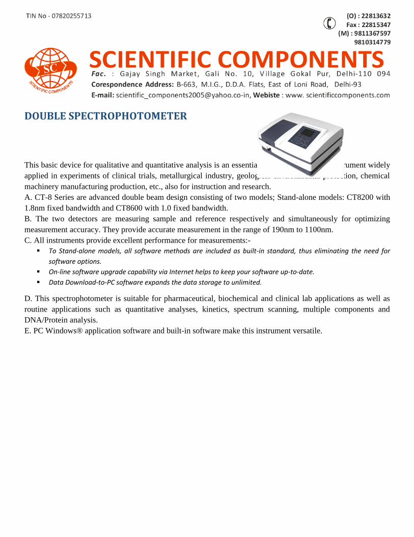
DOUBLE SPECTROPHOTOMETER This basic device for qualitative and quantitative analysis is an essential laboratory analytical instrument widely
applied in experiments of clinical trials, metallurgical industry, geological environmental protection, chemical
machinery manufacturing production, etc., also for instruction and research.
A. CT-8 Series are advanced double beam design consisting of two models; Stand-alone models: CT8200 with
1.8nm fixed bandwidth and CT8600 with 1.0 fixed bandwidth.
B. The two detectors are measuring sample and reference respectively and simultaneously for optimizing
measurement accuracy. They provide accurate measurement in the range of 190nm to 1100nm.
C. All instruments provide excellent performance for measurements:-
To Stand-alone models, all software methods are included as built-in standard, thus eliminating the need for
software options.
On-line software upgrade capability via Internet helps to keep your software up-to-date.
Data Download-to-PC software expands the data storage to unlimited.
D. This spectrophotometer is suitable for pharmaceutical, biochemical and clinical lab applications as well as
routine applications such as quantitative analyses, kinetics, spectrum scanning, multiple components and
DNA/Protein analysis.
E. PC Windows® application software and built-in software make this instrument versatile.

FEATURES: Stand-alone models with large graphic LCD display (320 × 240) to directly show graphs on the screen.
B. Unique pre-aligned deuterium lamp for easy lamp replacement to avoid optical adjustment.
C. GLP self-calibrated function can automatically check wavelength and photometric accuracy using validation
report.
D. Powerful integrated software for data acquisition:-
Quantitative. Kinetics.
Wavelength Scanning.
Multi-Wavelength.
DNA/Protein
E. Other features include:-
System examination: Automatic wavelength check, automatic light filter detection, automatic energy detection,
and other automatic functions.
Photometric switch: Able to switch light source in the specific range.
Photometric cutoff: Automatic cutoff of deuterium lamp and halogen lamp to extend their durability.
Power failure protection: Research data can be saved and restored when there is power failure.
Software: Application software can be connected to computer to control equipment operation and analyze
experimental data.
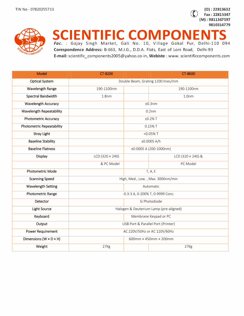
Model CT-8200 CT-8600
Optical System Double Beam, Grating 1200 lines/mm
Wavelength Range 190-1100nm 190-1100nm
Spectral Bandwidth 1.8nm 1.0nm
Wavelength Accuracy ±0.3nm
Wavelength Repeatability 0.2nm
Photometric Accuracy ±0.2% T
Photometric Repeatability 0.15% T
Stray Light <0.05% T
Baseline Stability ±0.0005 A/h
Baseline Flatness ±0.0005 A (200-1000nm)
Display LCD (320 × 240) LCD (320 × 240) &
& PC Model PC Model
Photometric Mode T, A, E
Scanning Speed High, Med., Low. , Max. 3000nm/min
Wavelength Setting Automatic
Photometric Range -0.3-3 A, 0-200% T, 0-9999 Conc.
Detector Si Photodiode
Light Source Halogen & Deuterium Lamp (pre-aligned)
Keyboard Membrane Keypad or PC
Output USB Port & Parallel Port (Printer)
Power Requirement AC 220V/50Hz or AC 110V/60Hz
Dimensions (W × D × H) 600mm × 450mm × 200mm
Weight 27Kg 27Kg
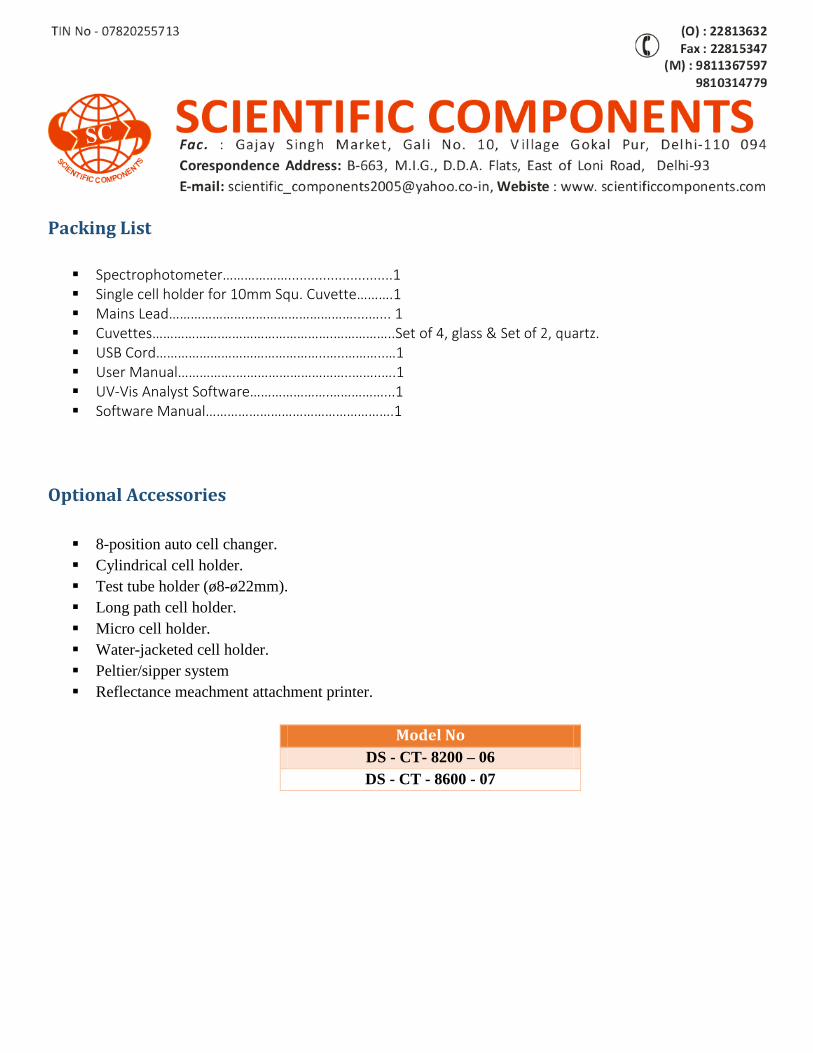
Packing List Spectrophotometer………………...........................1 Single cell holder for 10mm Squ. Cuvette……….1 Mains Lead……………………………………………....…... 1 Cuvettes……………….………………………….……………..Set of 4, glass & Set of 2, quartz. USB Cord………………………………………..…..………..…1 User Manual…………….…………………………..……..….1 UV-Vis Analyst Software………………….……………...1 Software Manual…………………………………………….1
Optional Accessories 8-position auto cell changer.
Cylindrical cell holder.
Test tube holder (ø8-ø22mm).
Long path cell holder.
Micro cell holder.
Water-jacketed cell holder.
Peltier/sipper system
Reflectance meachment attachment printer.
Model No
DS - CT- 8200 – 06
DS - CT - 8600 - 07
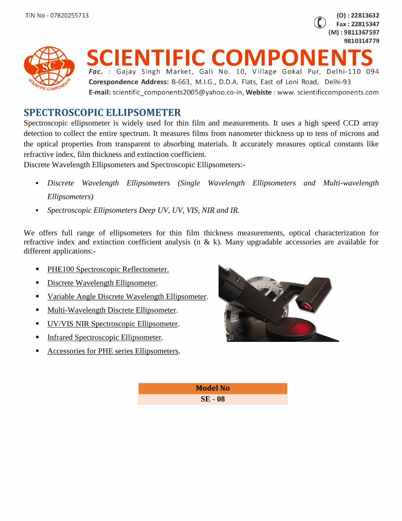
SPECTROSCOPIC ELLIPSOMETER Spectroscopic ellipsometer is widely used for thin film and measurements. It uses a high speed CCD array
detection to collect the entire spectrum. It measures films from nanometer thickness up to tens of microns and
the optical properties from transparent to absorbing materials. It accurately measures optical constants like
refractive index, film thickness and extinction coefficient.
Discrete Wavelength Ellipsometers and Spectroscopic Ellipsometers:-
Discrete Wavelength Ellipsometers (Single Wavelength Ellipsometers and Multi-wavelength
Ellipsometers)
Spectroscopic Ellipsometers Deep UV, UV, VIS, NIR and IR.
We offers full range of ellipsometers for thin film thickness measurements, optical characterization for
refractive index and extinction coefficient analysis (n & k). Many upgradable accessories are available for
different applications:-
PHE100 Spectroscopic Reflectometer.
Discrete Wavelength Ellipsometer.
Variable Angle Discrete Wavelength Ellipsometer.
Multi-Wavelength Discrete Ellipsometer.
UV/VIS NIR Spectroscopic Ellipsometer.
Infrared Spectroscopic Ellipsometer.
Accessories for PHE series Ellipsometers.
Model No
SE - 08
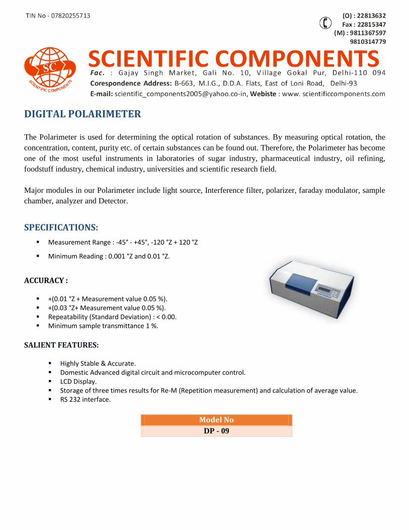
DIGITAL POLARIMETER The Polarimeter is used for determining the optical rotation of substances. By measuring optical rotation, the
concentration, content, purity etc. of certain substances can be found out. Therefore, the Polarimeter has become
one of the most useful instruments in laboratories of sugar industry, pharmaceutical industry, oil refining,
foodstuff industry, chemical industry, universities and scientific research field.
Major modules in our Polarimeter include light source, Interference filter, polarizer, faraday modulator, sample
chamber, analyzer and Detector.
SPECIFICATIONS:
Measurement Range : -45° - +45°, -120 °Z + 120 °Z
Minimum Reading : 0.001 °Z and 0.01 °Z.
ACCURACY :
+(0.01 °Z + Measurement value 0.05 %). +(0.03 °Z+ Measurement value 0.05 %). Repeatability (Standard Deviation) : < 0.00. Minimum sample transmittance 1 %.
SALIENT FEATURES:
Highly Stable & Accurate. Domestic Advanced digital circuit and microcomputer control. LCD Display. Storage of three times results for Re-M (Repetition measurement) and calculation of average value. RS 232 interface.
Model No
DP - 09
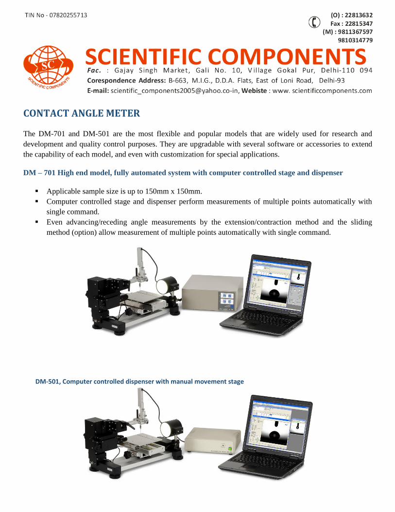
CONTACT ANGLE METER The DM-701 and DM-501 are the most flexible and popular models that are widely used for research and
development and quality control purposes. They are upgradable with several software or accessories to extend
the capability of each model, and even with customization for special applications.
DM – 701 High end model, fully automated system with computer controlled stage and dispenser
Applicable sample size is up to 150mm x 150mm.
Computer controlled stage and dispenser perform measurements of multiple points automatically with
single command.
Even advancing/receding angle measurements by the extension/contraction method and the sliding
method (option) allow measurement of multiple points automatically with single command.
DM-501, Computer controlled dispenser with manual movement stage
Applicable sample size is up to 150mm x 150mm.
Computer controlled automatic dispenser discharges precise volume of droplet in 0.1µL resolution.
Applicable to wide variety of optional accessories to extend the capability.
Capable functions of DM-701 / 501
Measurement of Contact Angle
Sessile Drop method: Typical contact angle in static and time function
Extension/Contraction method: Advancing/receding angles under captive drop.
Sliding method: Advancing/receding angles with tilted surface [Option]
Dynamic sliding method: Focusing the speed of droplet sliding [Option].
Three-state method: Bubble or oil droplet in water, or vice versa [Option].
Measurement of Surface/Interfacial Tension by Pendant Drop method [Optional kit needed].
Surface free energy analysis [Optional kit recommended].
Fast image capture system (Standard max. 60fps, Option max. 1,000fps).
Automatic dispenser.
Zoom lens.
Temperature control systems for solid and droplet [Option].
Multi dispensers for surface free energy analysis [Option].
Model No
CAM – DM 701 – 10
CAM – DM 501 - 11
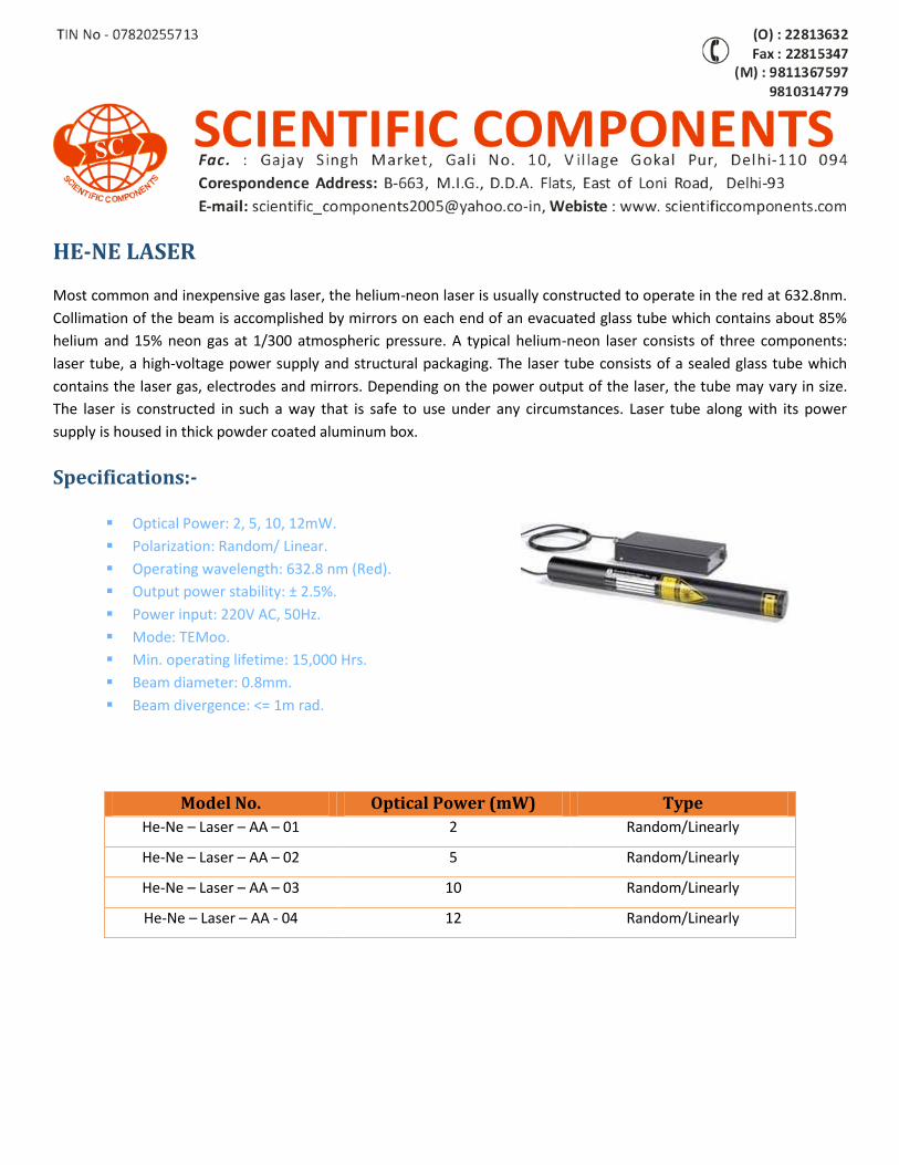
HE-NE LASER
Most common and inexpensive gas laser, the helium-neon laser is usually constructed to operate in the red at 632.8nm.
Collimation of the beam is accomplished by mirrors on each end of an evacuated glass tube which contains about 85%
helium and 15% neon gas at 1/300 atmospheric pressure. A typical helium-neon laser consists of three components:
laser tube, a high-voltage power supply and structural packaging. The laser tube consists of a sealed glass tube which
contains the laser gas, electrodes and mirrors. Depending on the power output of the laser, the tube may vary in size.
The laser is constructed in such a way that is safe to use under any circumstances. Laser tube along with its power
supply is housed in thick powder coated aluminum box.
Specifications:-
Optical Power: 2, 5, 10, 12mW.
Polarization: Random/ Linear.
Operating wavelength: 632.8 nm (Red).
Output power stability: ± 2.5%.
Power input: 220V AC, 50Hz.
Mode: TEMoo.
Min. operating lifetime: 15,000 Hrs.
Beam diameter: 0.8mm.
Beam divergence: <= 1m rad.
Model No. Optical Power (mW) Type
He-Ne – Laser – AA – 01 2 Random/Linearly
He-Ne – Laser – AA – 02 5 Random/Linearly
He-Ne – Laser – AA – 03 10 Random/Linearly
He-Ne – Laser – AA - 04 12 Random/Linearly
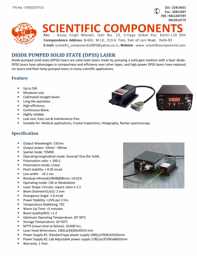
DIODE PUMPED SOLID STATE (DPSS) LASER Diode-pumped solid-state (DPSS) lasers are solid-state lasers made by pumping a solid gain medium with a laser diode. DPSS lasers have advantages in compactness and efficiency over other types, and high power DPSS lasers have replaced ion lasers and flash lamp-pumped lasers in many scientific applications.
Feature
Up to 5W. Miniature size. Collimated straight beam. Long life operation. High efficiency. Continuous Wave. Highly reliable. Low cost, Easy use & maintenance free. Suitable for: Medical applications, Crystal inspections, Holography, Raman spectroscopy.
Specification
Output Wavelength: 532nm Output power: 10mw ~ 80mw. Spatial mode: TEM00 Operating longitudinal mode: Several/ One (for SLM). Polarization ratio: > 100:1. Polarization mode: Linear Point stability: < 0.05 mrad.
Line width:<0.1 nm Residual infrared(1064&808nm): <0.01% Operating mode: CW or Modulation Laser Shape: Circular, aspect ratio<1.1:1 Beam Diameter(1/e2): 2 mm Divergence Angle: 1.0 mrad Power Stability: <±5% per 2 hrs. Temperature Stabilizing: TEC Warm Up Time: <5 minutes Beam quality(M2): <1.2 Optimum Operating Temperature: 20~30℃ Storage Temperature: 10~50℃ MTTF (mean time to failure): 10,000 hrs. Laser head dimensions: 100(L)x34(W)x45(H) mm Power Supply #1: Standard type power supply 100(L)x70(W)x55(H)mm Power Supply #2: Lab Adjustable power supply 178(L)x197(W)x84(H)mm Warranty: 1 Year.
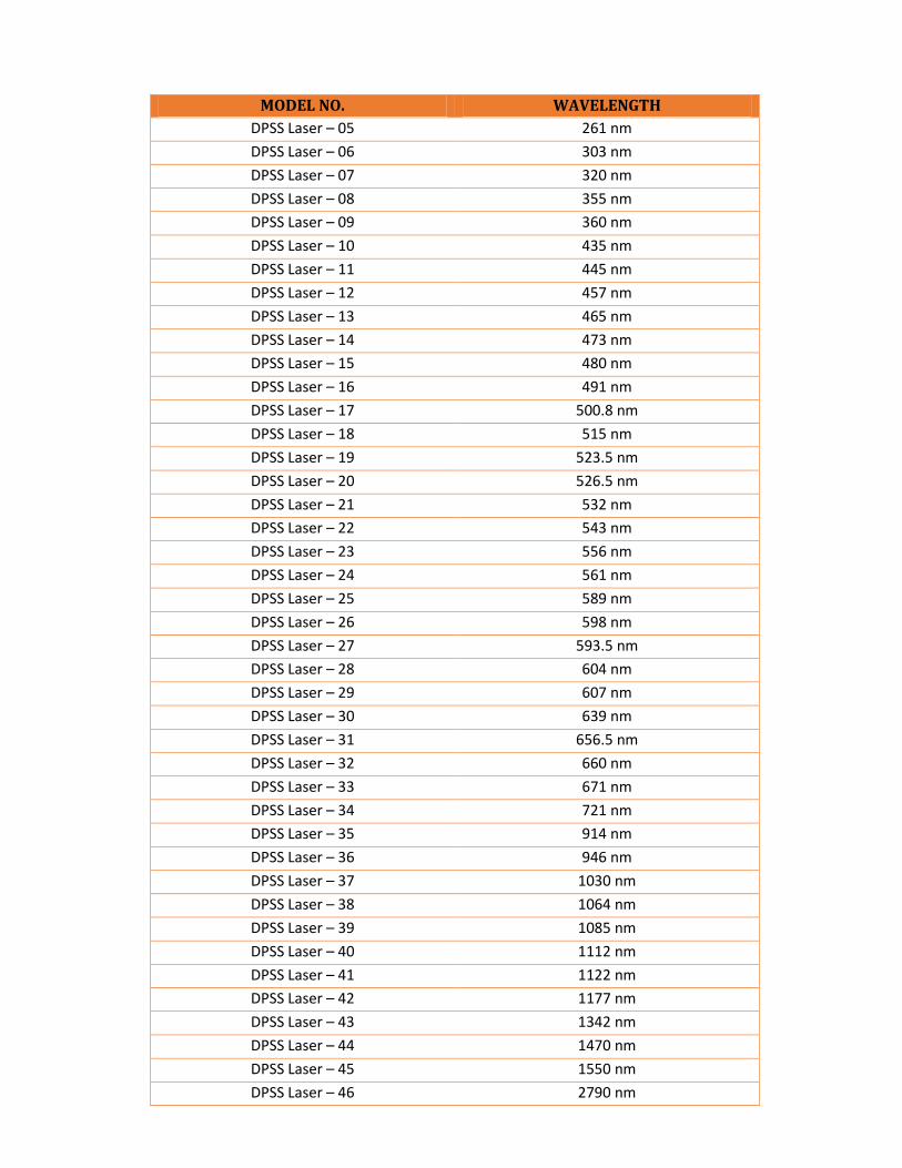
MODEL NO. WAVELENGTH
DPSS Laser – 05 261 nm
DPSS Laser – 06 303 nm
DPSS Laser – 07 320 nm
DPSS Laser – 08 355 nm
DPSS Laser – 09 360 nm
DPSS Laser – 10 435 nm
DPSS Laser – 11 445 nm
DPSS Laser – 12 457 nm
DPSS Laser – 13 465 nm
DPSS Laser – 14 473 nm
DPSS Laser – 15 480 nm
DPSS Laser – 16 491 nm
DPSS Laser – 17 500.8 nm
DPSS Laser – 18 515 nm
DPSS Laser – 19 523.5 nm
DPSS Laser – 20 526.5 nm
DPSS Laser – 21 532 nm
DPSS Laser – 22 543 nm
DPSS Laser – 23 556 nm
DPSS Laser – 24 561 nm
DPSS Laser – 25 589 nm
DPSS Laser – 26 598 nm
DPSS Laser – 27 593.5 nm
DPSS Laser – 28 604 nm
DPSS Laser – 29 607 nm
DPSS Laser – 30 639 nm
DPSS Laser – 31 656.5 nm
DPSS Laser – 32 660 nm
DPSS Laser – 33 671 nm
DPSS Laser – 34 721 nm
DPSS Laser – 35 914 nm
DPSS Laser – 36 946 nm
DPSS Laser – 37 1030 nm
DPSS Laser – 38 1064 nm
DPSS Laser – 39 1085 nm
DPSS Laser – 40 1112 nm
DPSS Laser – 41 1122 nm
DPSS Laser – 42 1177 nm
DPSS Laser – 43 1342 nm
DPSS Laser – 44 1470 nm
DPSS Laser – 45 1550 nm
DPSS Laser – 46 2790 nm
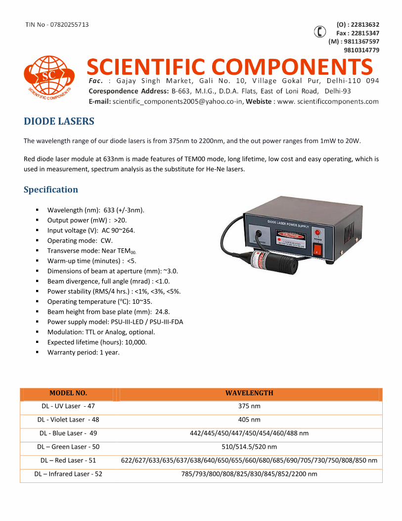
DIODE LASERS
The wavelength range of our diode lasers is from 375nm to 2200nm, and the out power ranges from 1mW to 20W.
Red diode laser module at 633nm is made features of TEM00 mode, long lifetime, low cost and easy operating, which is
used in measurement, spectrum analysis as the substitute for He-Ne lasers.
Specification
Wavelength (nm): 633 (+/-3nm).
Output power (mW) : >20.
Input voltage (V): AC 90~264.
Operating mode: CW.
Transverse mode: Near TEM00.
Warm-up time (minutes) : <5.
Dimensions of beam at aperture (mm): ~3.0.
Beam divergence, full angle (mrad) : <1.0.
Power stability (RMS/4 hrs.) : <1%, <3%, <5%.
Operating temperature (℃): 10~35.
Beam height from base plate (mm): 24.8.
Power supply model: PSU-III-LED / PSU-III-FDA
Modulation: TTL or Analog, optional.
Expected lifetime (hours): 10,000.
Warranty period: 1 year.
MODEL NO. WAVELENGTH
DL - UV Laser - 47 375 nm
DL - Violet Laser - 48 405 nm
DL - Blue Laser - 49 442/445/450/447/450/454/460/488 nm
DL – Green Laser - 50 510/514.5/520 nm
DL – Red Laser - 51 622/627/633/635/637/638/640/650/655/660/680/685/690/705/730/750/808/850 nm
DL – Infrared Laser - 52 785/793/800/808/825/830/845/852/2200 nm
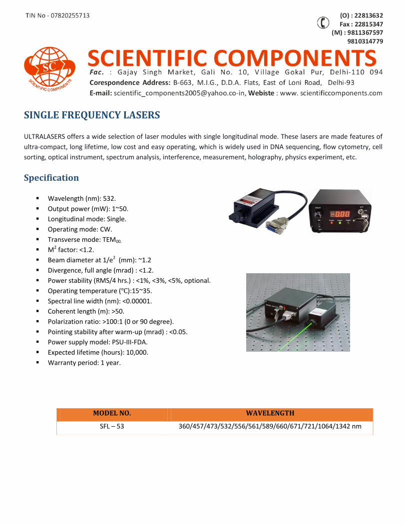
SINGLE FREQUENCY LASERS
ULTRALASERS offers a wide selection of laser modules with single longitudinal mode. These lasers are made features of
ultra-compact, long lifetime, low cost and easy operating, which is widely used in DNA sequencing, flow cytometry, cell
sorting, optical instrument, spectrum analysis, interference, measurement, holography, physics experiment, etc.
Specification
Wavelength (nm): 532.
Output power (mW): 1~50.
Longitudinal mode: Single.
Operating mode: CW.
Transverse mode: TEM00.
M2 factor: <1.2.
Beam diameter at 1/e2 (mm): ~1.2
Divergence, full angle (mrad) : <1.2.
Power stability (RMS/4 hrs.) : <1%, <3%, <5%, optional.
Operating temperature (℃):15~35.
Spectral line width (nm): <0.00001.
Coherent length (m): >50.
Polarization ratio: >100:1 (0 or 90 degree).
Pointing stability after warm-up (mrad) : <0.05.
Power supply model: PSU-III-FDA.
Expected lifetime (hours): 10,000.
Warranty period: 1 year.
MODEL NO. WAVELENGTH
SFL – 53 360/457/473/532/556/561/589/660/671/721/1064/1342 nm
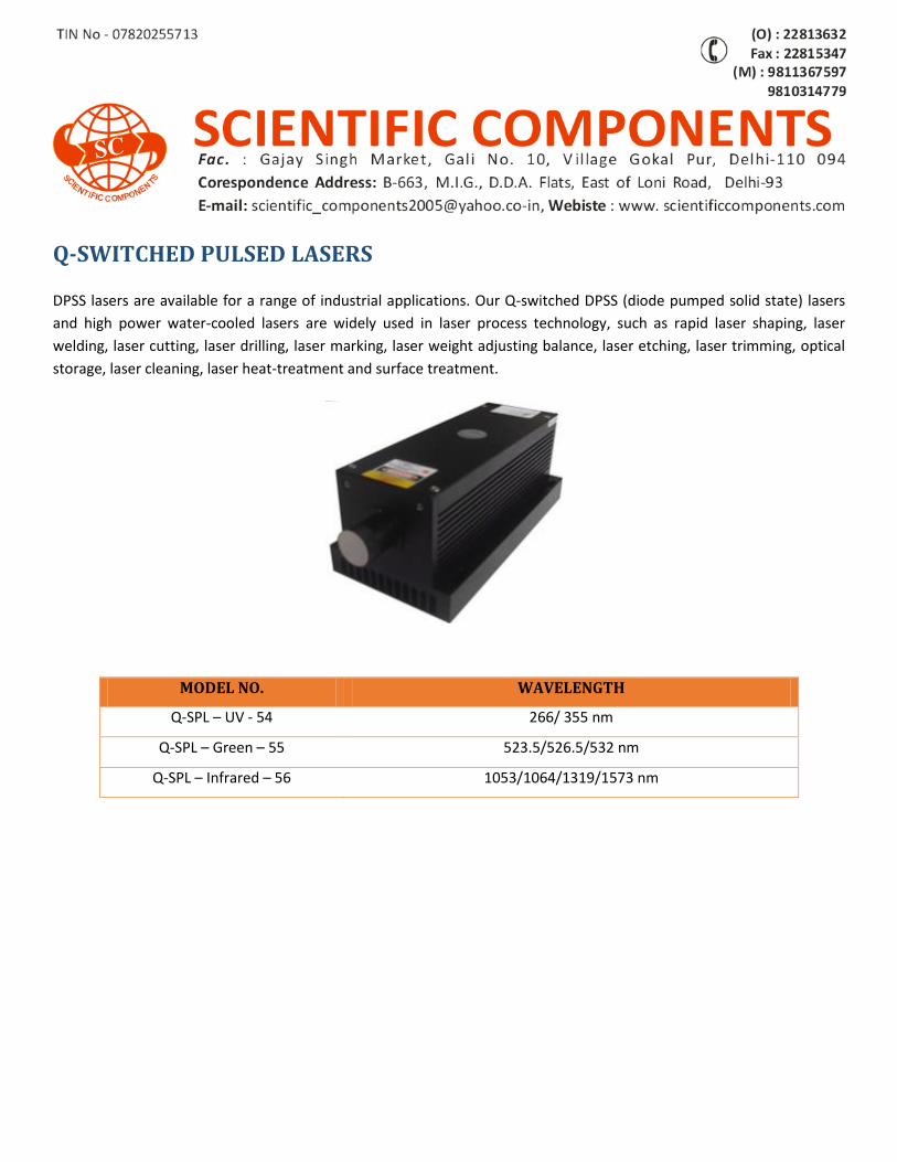
Q-SWITCHED PULSED LASERS
DPSS lasers are available for a range of industrial applications. Our Q-switched DPSS (diode pumped solid state) lasers
and high power water-cooled lasers are widely used in laser process technology, such as rapid laser shaping, laser
welding, laser cutting, laser drilling, laser marking, laser weight adjusting balance, laser etching, laser trimming, optical
storage, laser cleaning, laser heat-treatment and surface treatment.
MODEL NO. WAVELENGTH
Q-SPL – UV - 54 266/ 355 nm
Q-SPL – Green – 55 523.5/526.5/532 nm
Q-SPL – Infrared – 56 1053/1064/1319/1573 nm
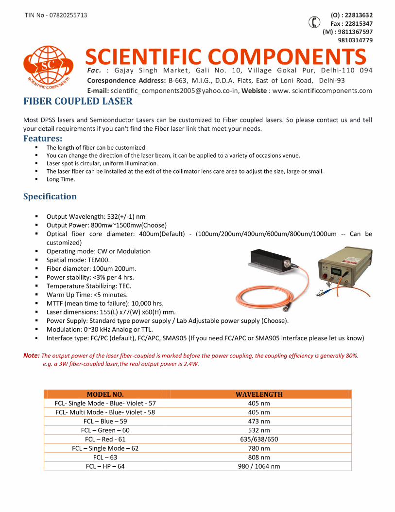
FIBER COUPLED LASER Most DPSS lasers and Semiconductor Lasers can be customized to Fiber coupled lasers. So please contact us and tell your detail requirements if you can't find the Fiber laser link that meet your needs.
Features: The length of fiber can be customized. You can change the direction of the laser beam, it can be applied to a variety of occasions venue. Laser spot is circular, uniform illumination. The laser fiber can be installed at the exit of the collimator lens care area to adjust the size, large or small. Long Time.
Specification
Output Wavelength: 532(+/-1) nm Output Power: 800mw~1500mw(Choose) Optical fiber core diameter: 400um(Default) - (100um/200um/400um/600um/800um/1000um -- Can be
customized) Operating mode: CW or Modulation Spatial mode: TEM00. Fiber diameter: 100um 200um. Power stability: <3% per 4 hrs. Temperature Stabilizing: TEC. Warm Up Time: <5 minutes. MTTF (mean time to failure): 10,000 hrs. Laser dimensions: 155(L) x77(W) x60(H) mm. Power Supply: Standard type power supply / Lab Adjustable power supply (Choose). Modulation: 0~30 kHz Analog or TTL. Interface type: FC/PC (default), FC/APC, SMA905 (If you need FC/APC or SMA905 interface please let us know)
Note: The output power of the laser fiber-coupled is marked before the power coupling, the coupling efficiency is generally 80%.
e.g. a 3W fiber-coupled laser,the real output power is 2.4W.
MODEL NO. WAVELENGTH FCL- Single Mode - Blue- Violet - 57 405 nm
FCL- Multi Mode - Blue- Violet - 58 405 nm
FCL – Blue – 59 473 nm
FCL – Green – 60 532 nm
FCL – Red - 61 635/638/650
FCL – Single Mode – 62 780 nm
FCL – 63 808 nm
FCL – HP – 64 980 / 1064 nm
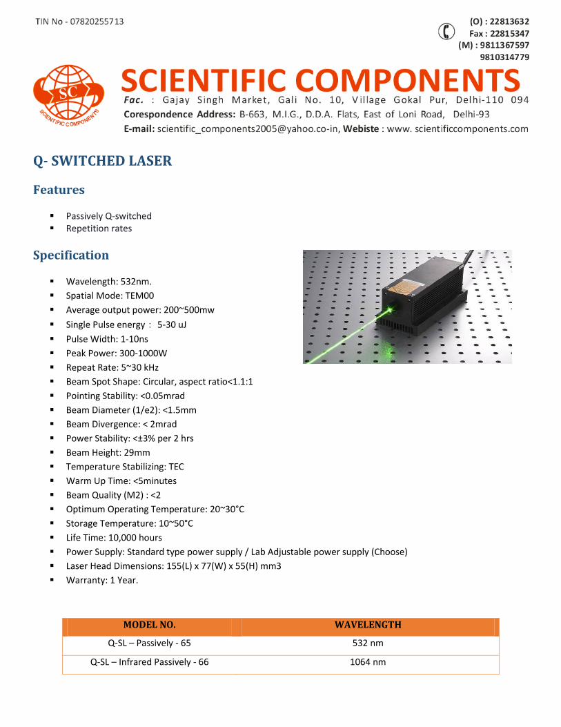
Q- SWITCHED LASER
Features
Passively Q-switched Repetition rates
Specification
Wavelength: 532nm.
Spatial Mode: TEM00
Average output power: 200~500mw
Single Pulse energy: 5-30 uJ
Pulse Width: 1-10ns
Peak Power: 300-1000W
Repeat Rate: 5~30 kHz
Beam Spot Shape: Circular, aspect ratio<1.1:1
Pointing Stability: <0.05mrad
Beam Diameter (1/e2): <1.5mm
Beam Divergence: < 2mrad
Power Stability: <±3% per 2 hrs
Beam Height: 29mm
Temperature Stabilizing: TEC
Warm Up Time: <5minutes
Beam Quality (M2) : <2
Optimum Operating Temperature: 20~30°C
Storage Temperature: 10~50°C
Life Time: 10,000 hours
Power Supply: Standard type power supply / Lab Adjustable power supply (Choose)
Laser Head Dimensions: 155(L) x 77(W) x 55(H) mm3
Warranty: 1 Year.
MODEL NO. WAVELENGTH
Q-SL – Passively - 65 532 nm
Q-SL – Infrared Passively - 66 1064 nm
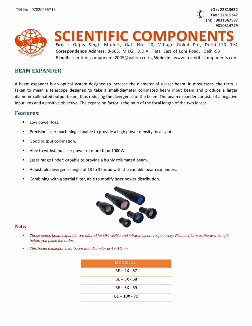
BEAM EXPANDER
A beam expander is an optical system designed to increase the diameter of a laser beam. In most cases, the term is
taken to mean a telescope designed to take a small-diameter collimated beam input beam and produce a larger
diameter collimated output beam, thus reducing the divergence of the beam. The beam expander consists of a negative
input lens and a positive objective. The expansion factor is the ratio of the focal length of the two lenses.
Features:
Low power loss.
Precision laser machining: capable to provide a high power density focal spot.
Good output collimation.
Able to withstand laser power of more than 1000W.
Laser range finder: capable to provide a highly collimated beam.
Adjustable divergence angle of 18 to 32mrad with the variable beam expanders.
Combining with a spatial filter, able to modify laser power distribution.
Note:
These series beam expander are offered for UV, visible and infrared lasers respectively. Please inform us the wavelength
before you place the order.
This beam expander is for beam with diameter of 4 ~ 10mm.
MODEL NO.
BE – 2X - 67
BE – 3X - 68
BE – 5X - 69
BE – 10X - 70
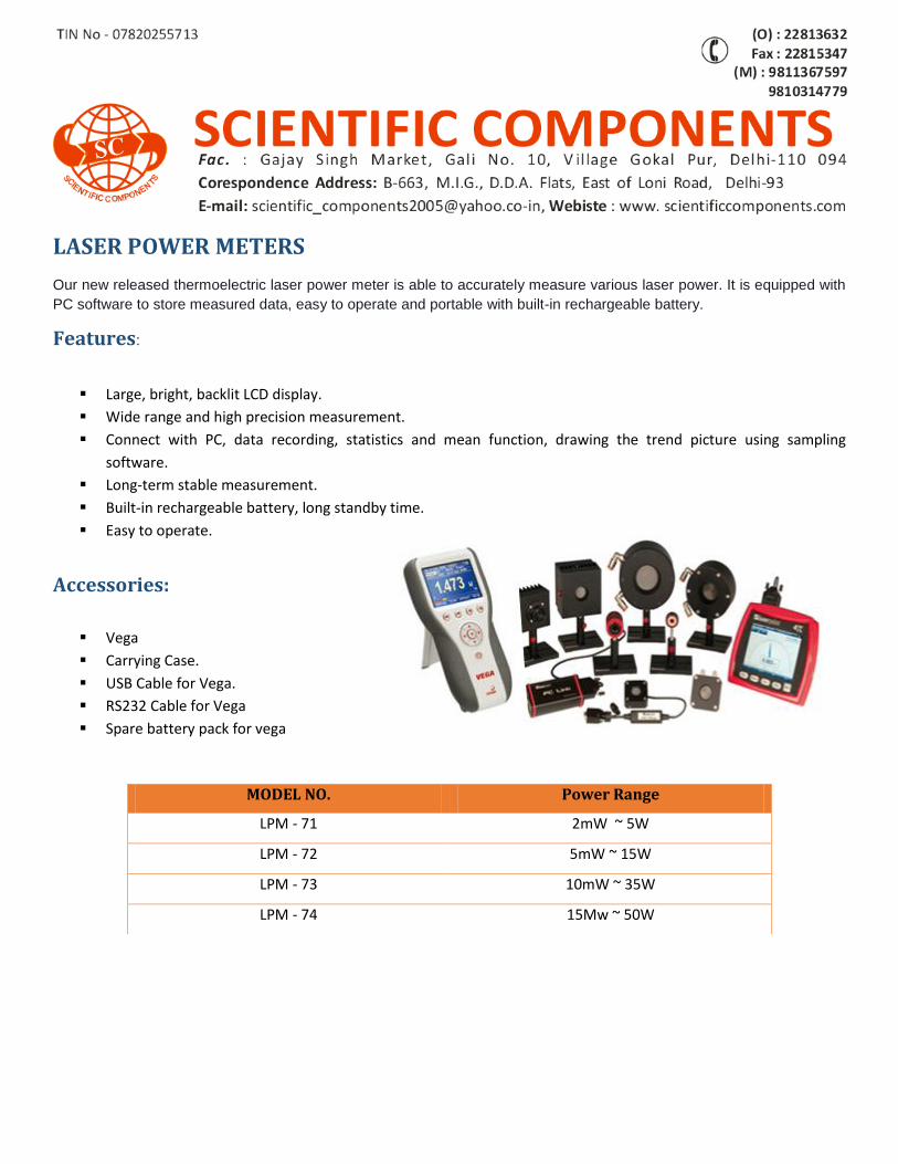
LASER POWER METERS
Our new released thermoelectric laser power meter is able to accurately measure various laser power. It is equipped with
PC software to store measured data, easy to operate and portable with built-in rechargeable battery.
Features:
Large, bright, backlit LCD display.
Wide range and high precision measurement.
Connect with PC, data recording, statistics and mean function, drawing the trend picture using sampling
software.
Long-term stable measurement.
Built-in rechargeable battery, long standby time.
Easy to operate.
Accessories:
Vega
Carrying Case.
USB Cable for Vega.
RS232 Cable for Vega
Spare battery pack for vega
MODEL NO. Power Range
LPM - 71 2mW ~ 5W
LPM - 72 5mW ~ 15W
LPM - 73 10mW ~ 35W
LPM - 74 15Mw ~ 50W
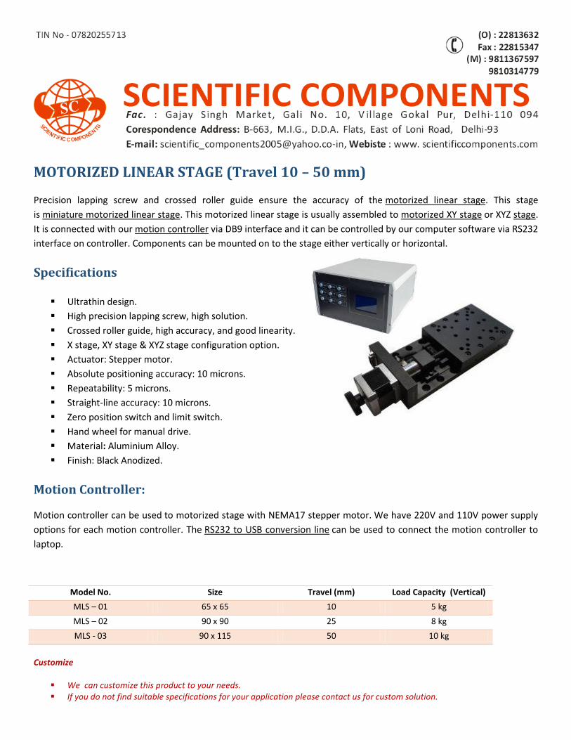
MOTORIZED LINEAR STAGE (Travel 10 – 50 mm)
Precision lapping screw and crossed roller guide ensure the accuracy of the motorized linear stage. This stage
is miniature motorized linear stage. This motorized linear stage is usually assembled to motorized XY stage or XYZ stage.
It is connected with our motion controller via DB9 interface and it can be controlled by our computer software via RS232
interface on controller. Components can be mounted on to the stage either vertically or horizontal.
Specifications
Ultrathin design.
High precision lapping screw, high solution.
Crossed roller guide, high accuracy, and good linearity.
X stage, XY stage & XYZ stage configuration option.
Actuator: Stepper motor.
Absolute positioning accuracy: 10 microns.
Repeatability: 5 microns.
Straight-line accuracy: 10 microns.
Zero position switch and limit switch.
Hand wheel for manual drive.
Material: Aluminium Alloy.
Finish: Black Anodized.
Motion Controller:
Motion controller can be used to motorized stage with NEMA17 stepper motor. We have 220V and 110V power supply
options for each motion controller. The RS232 to USB conversion line can be used to connect the motion controller to
laptop.
Customize
We can customize this product to your needs. If you do not find suitable specifications for your application please contact us for custom solution.
Model No. Size Travel (mm) Load Capacity (Vertical)
MLS – 01 65 x 65 10 5 kg
MLS – 02 90 x 90 25 8 kg
MLS - 03 90 x 115 50 10 kg
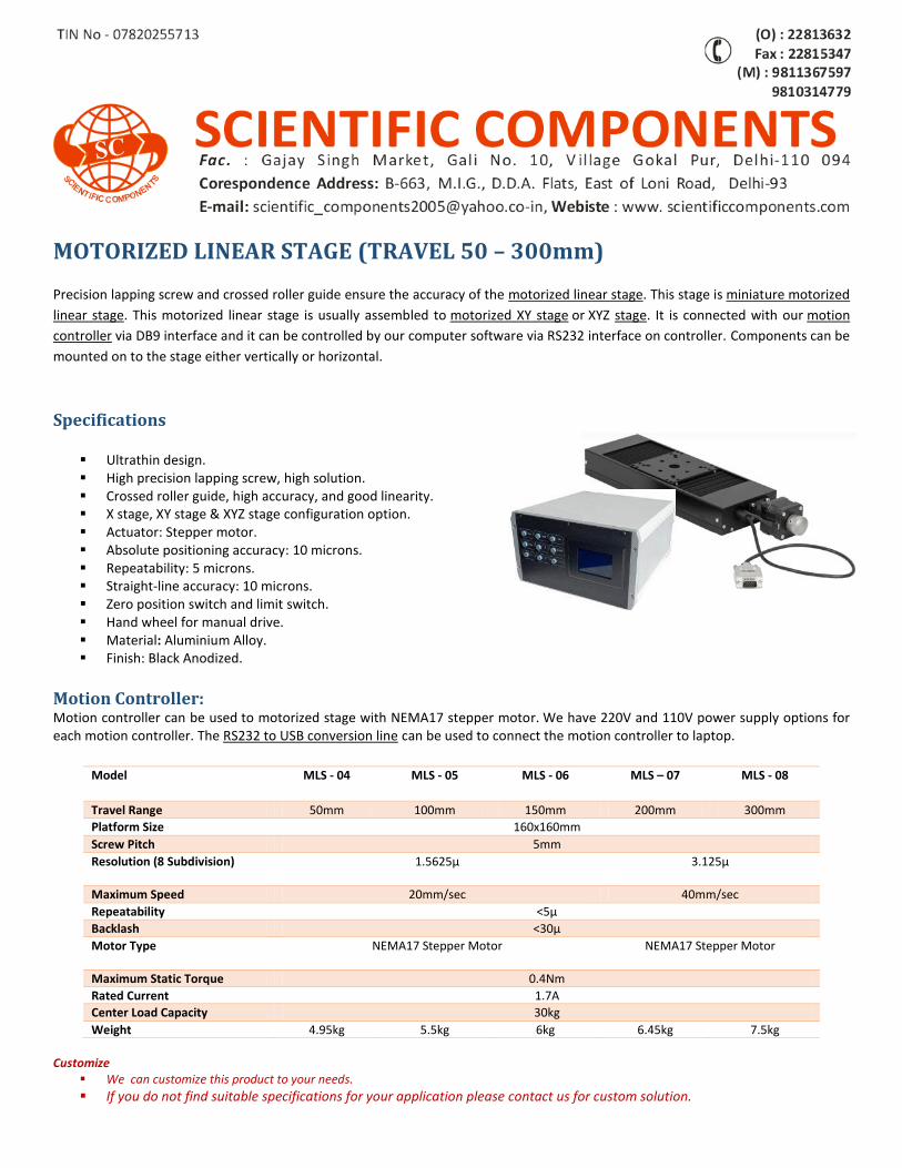
MOTORIZED LINEAR STAGE (TRAVEL 50 – 300mm)
Precision lapping screw and crossed roller guide ensure the accuracy of the motorized linear stage. This stage is miniature motorized
linear stage. This motorized linear stage is usually assembled to motorized XY stage or XYZ stage. It is connected with our motion
controller via DB9 interface and it can be controlled by our computer software via RS232 interface on controller. Components can be
mounted on to the stage either vertically or horizontal.
Specifications
Ultrathin design. High precision lapping screw, high solution. Crossed roller guide, high accuracy, and good linearity. X stage, XY stage & XYZ stage configuration option. Actuator: Stepper motor. Absolute positioning accuracy: 10 microns. Repeatability: 5 microns. Straight-line accuracy: 10 microns. Zero position switch and limit switch. Hand wheel for manual drive. Material: Aluminium Alloy. Finish: Black Anodized.
Motion Controller: Motion controller can be used to motorized stage with NEMA17 stepper motor. We have 220V and 110V power supply options for each motion controller. The RS232 to USB conversion line can be used to connect the motion controller to laptop.
Customize
We can customize this product to your needs.
If you do not find suitable specifications for your application please contact us for custom solution.
Model MLS - 04 MLS - 05 MLS - 06 MLS – 07 MLS - 08
Travel Range 50mm 100mm 150mm 200mm 300mm
Platform Size 160x160mm
Screw Pitch 5mm
Resolution (8 Subdivision) 1.5625μ 3.125μ
Maximum Speed 20mm/sec 40mm/sec
Repeatability <5μ
Backlash <30μ
Motor Type NEMA17 Stepper Motor NEMA17 Stepper Motor
Maximum Static Torque 0.4Nm
Rated Current 1.7A
Center Load Capacity 30kg
Weight 4.95kg 5.5kg 6kg 6.45kg 7.5kg
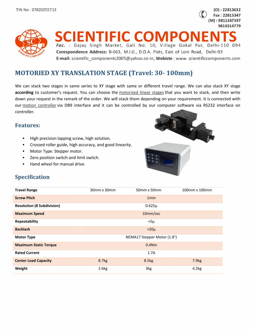
MOTORIED XY TRANSLATION STAGE (Travel: 30- 100mm)
We can stack two stages in same series to XY stage with same or different travel range. We can also stack XY stage
according to customer’s request. You can choose the motorized linear stages that you want to stack, and then write
down your request in the remark of the order. We will stack them depending on your requirement. It is connected with
our motion controller via DB9 interface and it can be controlled by our computer software via RS232 interface on
controller.
Features:
High precision lapping screw, high solution.
Crossed roller guide, high accuracy, and good linearity.
Motor Type: Stepper motor.
Zero position switch and limit switch.
Hand wheel for manual drive.
Specification
Travel Range 30mm x 30mm 50mm x 50mm 100mm x 100mm
Screw Pitch 1mm
Resolution (8 Subdivision) 0.625μ
Maximum Speed 10mm/sec
Repeatability <5μ
Backlash <20μ
Motor Type NEMA17 Stepper Motor (1.8°)
Maximum Static Torque 0.4Nm
Rated Current 1.7A
Center Load Capacity 8.7kg 8.5kg 7.9kg
Weight 2.6kg 3kg 4.2kg
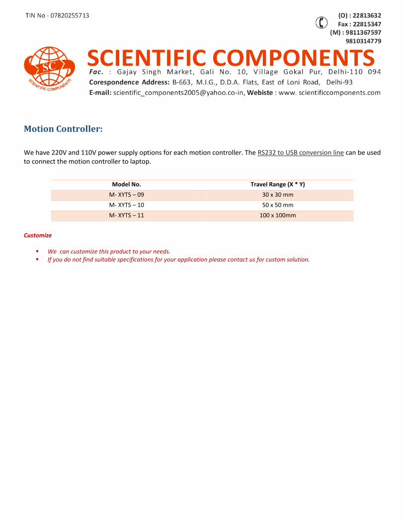
Motion Controller:
We have 220V and 110V power supply options for each motion controller. The RS232 to USB conversion line can be used to connect the motion controller to laptop. Customize
We can customize this product to your needs. If you do not find suitable specifications for your application please contact us for custom solution.
Model No. Travel Range (X * Y)
M- XYTS – 09 30 x 30 mm
M- XYTS – 10 50 x 50 mm
M- XYTS – 11 100 x 100mm
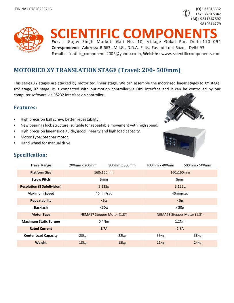
MOTORIED XY TRANSLATION STAGE (Travel: 200- 500mm)
This series XY stages are stacked by motorized linear stage. We can assemble the motorized linear stages to XY stage,
XYZ stage, XZ stage. It is connected with our motion controller via DB9 interface and it can be controlled by our
computer software via RS232 interface on controller.
Features:
High precision ball screw, better repeatability.
New bearings lock structure, suitable for repeatable movement with high speed.
High precision linear slide guide, good linearity and high load capacity.
Motor Type: Stepper motor.
Hand wheel for manual drive.
Specification:
Travel Range 200mm x 200mm 300mm x 300mm 400mm x 400mm 500mm x 500mm
Platform Size 160x160mm 160x160mm
Screw Pitch 5mm 5mm
Resolution (8 Subdivision) 3.125μ 3.125μ
Maximum Speed 40mm/sec 40mm/sec
Repeatability <5μ <5μ
Backlash <30μ <30μ
Motor Type NEMA17 Stepper Motor (1.8°) NEMA23 Stepper Motor (1.8°)
Maximum Static Torque 0.4Nm 1.2Nm
Rated Current 1.7A 2.8A
Center Load Capacity 23kg 22kg 39kg 38kg
Weight 13kg 15kg 21kg 24kg
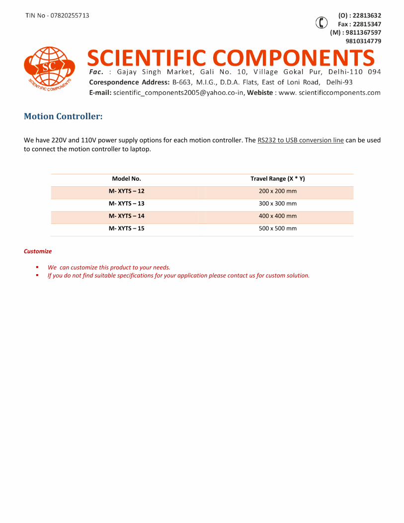
Motion Controller:
We have 220V and 110V power supply options for each motion controller. The RS232 to USB conversion line can be used to connect the motion controller to laptop.
Customize
We can customize this product to your needs. If you do not find suitable specifications for your application please contact us for custom solution.
Model No. Travel Range (X * Y)
M- XYTS – 12 200 x 200 mm
M- XYTS – 13 300 x 300 mm
M- XYTS – 14 400 x 400 mm
M- XYTS – 15 500 x 500 mm
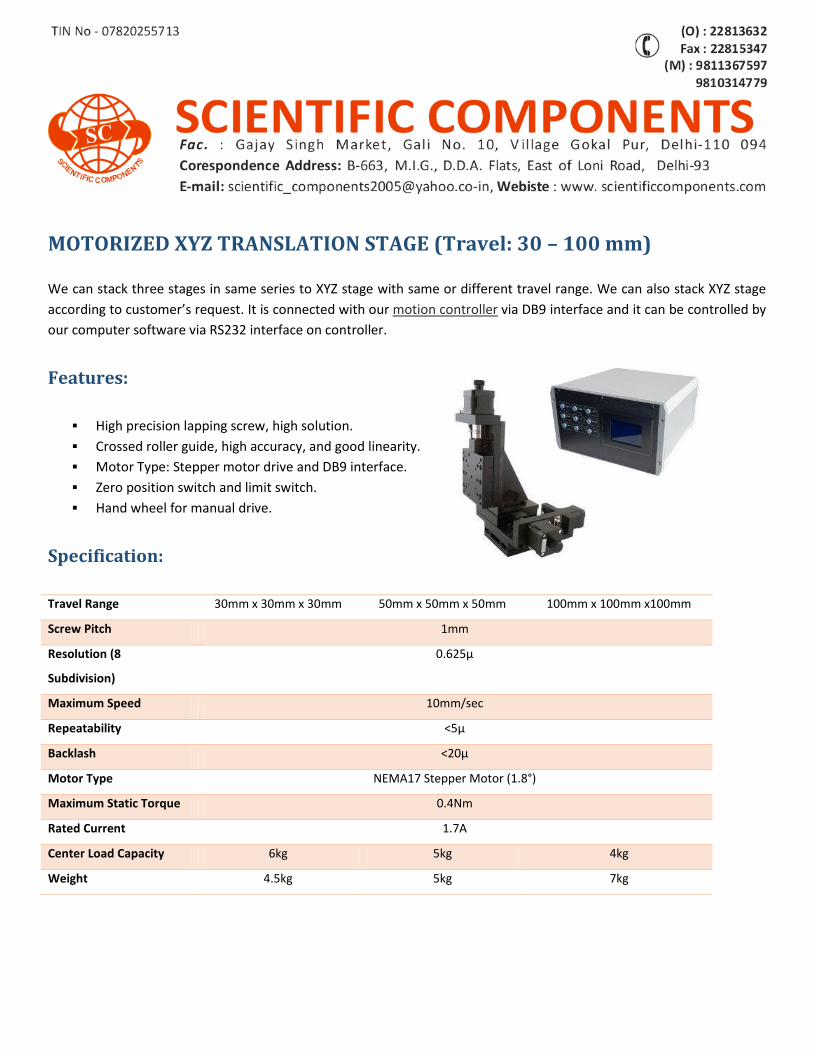
MOTORIZED XYZ TRANSLATION STAGE (Travel: 30 – 100 mm)
We can stack three stages in same series to XYZ stage with same or different travel range. We can also stack XYZ stage
according to customer’s request. It is connected with our motion controller via DB9 interface and it can be controlled by
our computer software via RS232 interface on controller.
Features:
High precision lapping screw, high solution.
Crossed roller guide, high accuracy, and good linearity.
Motor Type: Stepper motor drive and DB9 interface.
Zero position switch and limit switch.
Hand wheel for manual drive.
Specification:
Travel Range 30mm x 30mm x 30mm 50mm x 50mm x 50mm 100mm x 100mm x100mm
Screw Pitch 1mm
Resolution (8
Subdivision)
0.625μ
Maximum Speed 10mm/sec
Repeatability <5μ
Backlash <20μ
Motor Type NEMA17 Stepper Motor (1.8°)
Maximum Static Torque 0.4Nm
Rated Current 1.7A
Center Load Capacity 6kg 5kg 4kg
Weight 4.5kg 5kg 7kg
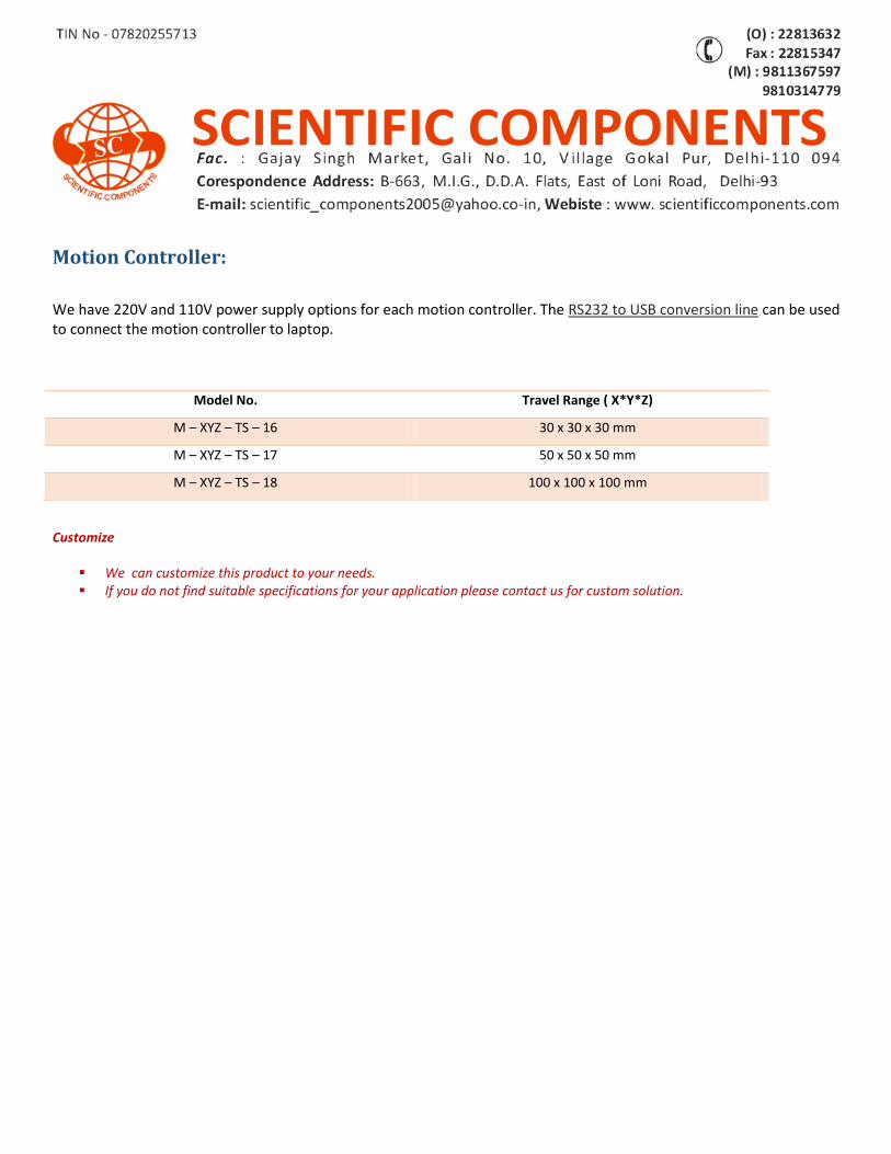
Motion Controller:
We have 220V and 110V power supply options for each motion controller. The RS232 to USB conversion line can be used to connect the motion controller to laptop.
Model No. Travel Range ( X*Y*Z)
M – XYZ – TS – 16 30 x 30 x 30 mm
M – XYZ – TS – 17 50 x 50 x 50 mm
M – XYZ – TS – 18 100 x 100 x 100 mm
Customize
We can customize this product to your needs. If you do not find suitable specifications for your application please contact us for custom solution.
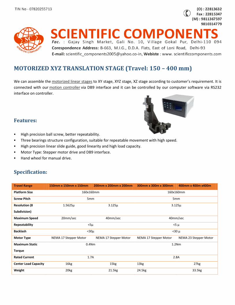
MOTORIZED XYZ TRANSLATION STAGE (Travel: 150 – 400 mm)
We can assemble the motorized linear stages to XY stage, XYZ stage, XZ stage according to customer’s requirement. It is
connected with our motion controller via DB9 interface and it can be controlled by our computer software via RS232
interface on controller.
Features:
High precision ball screw, better repeatability.
Three bearings structure configuration, suitable for repeatable movement with high speed.
High precision linear slide guide, good linearity and high load capacity.
Motor Type: Stepper motor drive and DB9 interface.
Hand wheel for manual drive.
Specification:
Travel Range 150mm x 150mm x 150mm 200mm x 200mm x 200mm 300mm x 300m x 300mm 400mm x 400m x400m
Platform Size 160x160mm 160x160mm
Screw Pitch 5mm 5mm
Resolution (8
Subdivision)
1.5625μ 3.125μ 3.125μ
Maximum Speed 20mm/sec 40mm/sec 40mm/sec
Repeatability <5μ <5 μ
Backlash <30μ <30 μ
Motor Type NEMA 17 Stepper Motor NEMA 17 Stepper Motor NEMA 17 Stepper Motor NEMA 23 Stepper Motor
Maximum Static
Torque
0.4Nm 1.2Nm
Rated Current 1.7A 2.8A
Center Load Capacity 16kg 15kg 13kg 27kg
Weight 20kg 21.5kg 24.5kg 33.5kg
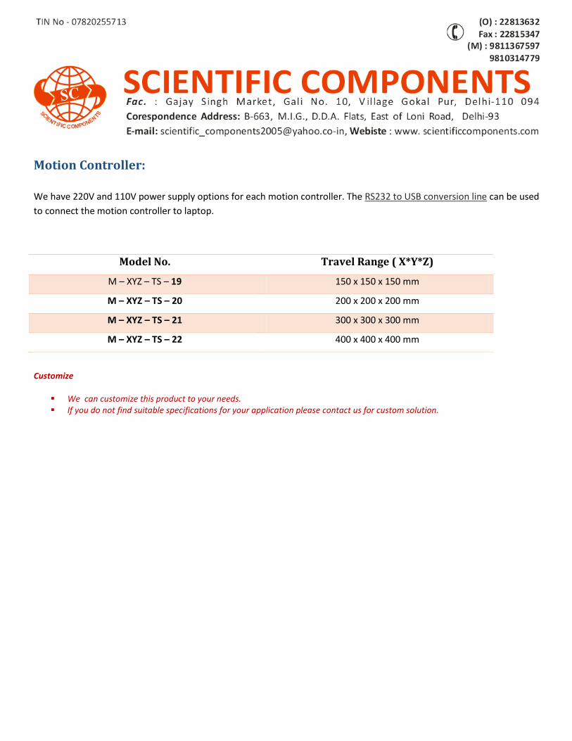
Motion Controller:
We have 220V and 110V power supply options for each motion controller. The RS232 to USB conversion line can be used
to connect the motion controller to laptop.
Model No. Travel Range ( X*Y*Z)
M – XYZ – TS – 19 150 x 150 x 150 mm
M – XYZ – TS – 20 200 x 200 x 200 mm
M – XYZ – TS – 21 300 x 300 x 300 mm
M – XYZ – TS – 22 400 x 400 x 400 mm
Customize
We can customize this product to your needs. If you do not find suitable specifications for your application please contact us for custom solution.
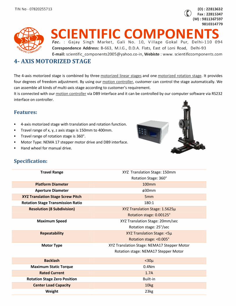
4- AXIS MOTORIZED STAGE
The 4-axis motorized stage is combined by three motorized linear stages and one motorized rotation stage. It provides
four degrees of freedom adjustment. By using our motion controller, customer can control the stage automatically. We
can assemble all kinds of multi-axis stage according to customer’s requirement.
It is connected with our motion controller via DB9 interface and it can be controlled by our computer software via RS232
interface on controller.
Features: 4-axis motorized stage with translation and rotation function.
Travel range of x, y, z axis stage is 150mm to 400mm.
Travel range of rotation stage is 360°.
Motor Type: NEMA 17 stepper motor drive and DB9 interface.
Hand wheel for manual drive.
Specification:
Travel Range XYZ Translation Stage: 150mm
Rotation Stage: 360°
Platform Diameter 100mm
Aperture Diameter ø30mm
XYZ Translation Stage Screw Pitch 5mm
Rotation Stage Transmission Ratio 180:1
Resolution (8 Subdivision) XYZ Translation Stage: 1.5625μ
Rotation stage: 0.00125°
Maximum Speed XYZ Translation Stage: 20mm/sec
Rotation stage: 25°/sec
Repeatability XYZ Translation Stage: <5μ
Rotation stage: <0.005°
Motor Type XYZ Translation Stage: NEMA17 Stepper Motor
Rotation stage: NEMA17 Stepper Motor
Backlash <30μ
Maximum Static Torque 0.4Nm
Rated Current 1.7A
Rotation Stage Zero Position Built-in
Center Load Capacity 10kg
Weight 23kg
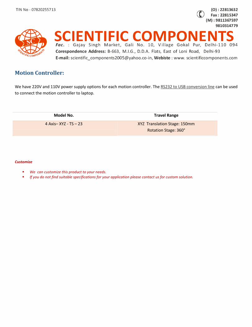
Motion Controller:
We have 220V and 110V power supply options for each motion controller. The RS232 to USB conversion line can be used
to connect the motion controller to laptop.
Model No. Travel Range
4 Axis– XYZ - TS – 23 XYZ Translation Stage: 150mm
Rotation Stage: 360°
Customize
We can customize this product to your needs. If you do not find suitable specifications for your application please contact us for custom solution.
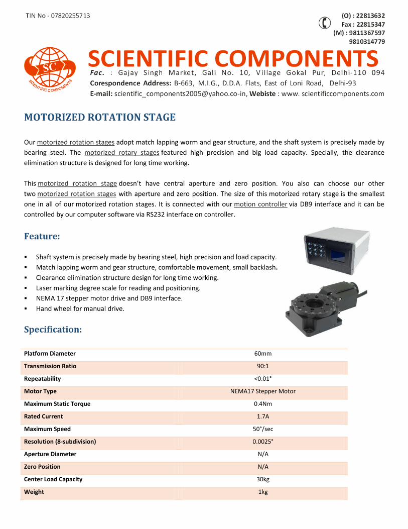
MOTORIZED ROTATION STAGE
Our motorized rotation stages adopt match lapping worm and gear structure, and the shaft system is precisely made by
bearing steel. The motorized rotary stages featured high precision and big load capacity. Specially, the clearance
elimination structure is designed for long time working.
This motorized rotation stage doesn’t have central aperture and zero position. You also can choose our other
two motorized rotation stages with aperture and zero position. The size of this motorized rotary stage is the smallest
one in all of our motorized rotation stages. It is connected with our motion controller via DB9 interface and it can be
controlled by our computer software via RS232 interface on controller.
Feature:
Shaft system is precisely made by bearing steel, high precision and load capacity.
Match lapping worm and gear structure, comfortable movement, small backlash.
Clearance elimination structure design for long time working.
Laser marking degree scale for reading and positioning.
NEMA 17 stepper motor drive and DB9 interface.
Hand wheel for manual drive.
Specification:
Platform Diameter 60mm
Transmission Ratio 90:1
Repeatability <0.01°
Motor Type NEMA17 Stepper Motor
Maximum Static Torque 0.4Nm
Rated Current 1.7A
Maximum Speed 50°/sec
Resolution (8-subdivision) 0.0025°
Aperture Diameter N/A
Zero Position N/A
Center Load Capacity 30kg
Weight 1kg
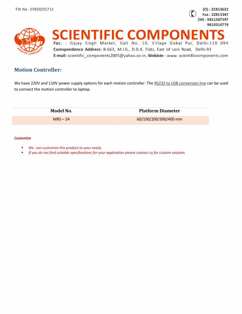
Motion Controller:
We have 220V and 110V power supply options for each motion controller. The RS232 to USB conversion line can be used
to connect the motion controller to laptop.
Model No. Platform Diameter
MRS – 24 60/100/200/300/400 mm
Customize
We can customize this product to your needs. If you do not find suitable specifications for your application please contact us for custom solution.
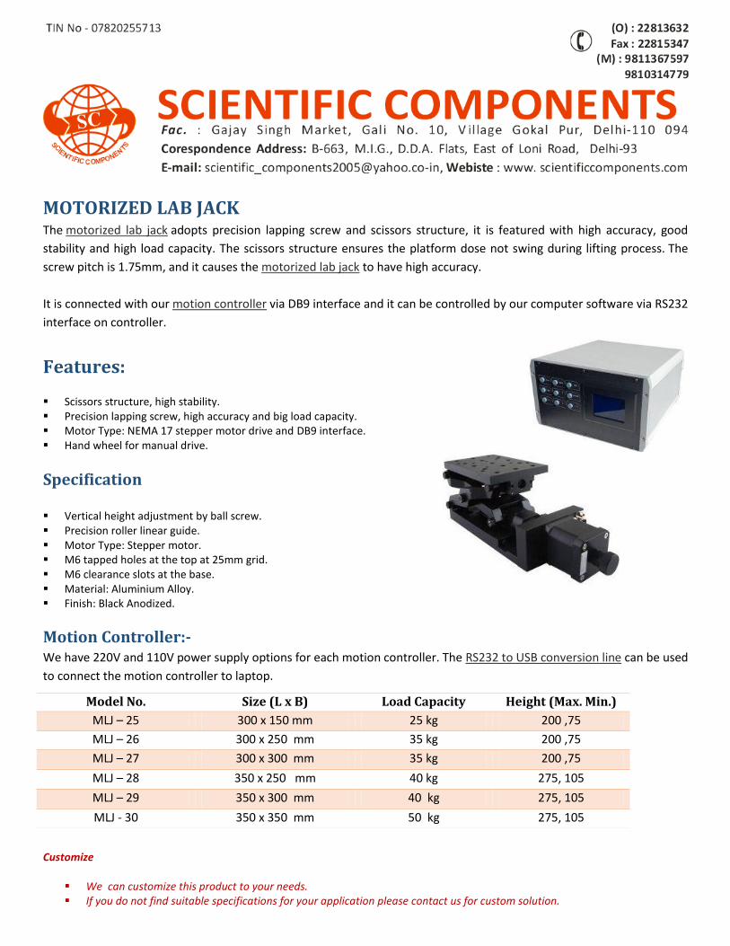
MOTORIZED LAB JACK The motorized lab jack adopts precision lapping screw and scissors structure, it is featured with high accuracy, good
stability and high load capacity. The scissors structure ensures the platform dose not swing during lifting process. The
screw pitch is 1.75mm, and it causes the motorized lab jack to have high accuracy.
It is connected with our motion controller via DB9 interface and it can be controlled by our computer software via RS232
interface on controller.
Features:
Scissors structure, high stability. Precision lapping screw, high accuracy and big load capacity. Motor Type: NEMA 17 stepper motor drive and DB9 interface. Hand wheel for manual drive.
Specification Vertical height adjustment by ball screw. Precision roller linear guide. Motor Type: Stepper motor. M6 tapped holes at the top at 25mm grid. M6 clearance slots at the base. Material: Aluminium Alloy. Finish: Black Anodized.
Motion Controller:- We have 220V and 110V power supply options for each motion controller. The RS232 to USB conversion line can be used
to connect the motion controller to laptop.
Customize
We can customize this product to your needs. If you do not find suitable specifications for your application please contact us for custom solution.
Model No. Size (L x B) Load Capacity Height (Max. Min.)
MLJ – 25 300 x 150 mm 25 kg 200 ,75
MLJ – 26 300 x 250 mm 35 kg 200 ,75
MLJ – 27 300 x 300 mm 35 kg 200 ,75
MLJ – 28 350 x 250 mm 40 kg 275, 105
MLJ – 29 350 x 300 mm 40 kg 275, 105
MLJ - 30 350 x 350 mm 50 kg 275, 105
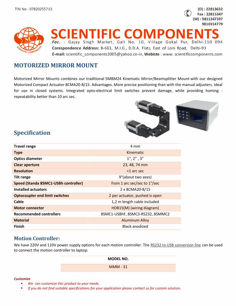
MOTORIZED MIRROR MOUNT Motorized Mirror Mounts combines our traditional 5MBM24 Kinematic Mirror/Beamsplitter Mount with our designed
Motorized Compact Actuator 8CMA20-8/15. Advantages. More precise positioning than with the manual adjusters. Ideal
for use in closed systems. Integrated opto-electrical limit switches prevent damage, while providing homing -
repeatability better than 10 arc sec.
Specification Travel range 4 mm
Type Kinematic
Optics diameter 1”, 2” , 3”
Clear aperture 23, 48, 74 mm
Resolution <1 arc sec
Tilt range 9°(about two axes)
Speed (Standa 8SMC1-USBh controller) from 1 arc sec/sec to 1°/sec
Installed actuators 2 x 8CMA20-8/15
Optocoupler end limit switches 2 per actuator, pushed is open
Cable 1,2 m length cable included
Motor connector HDB15(M) (wiring diagram)
Recommended controllers 8SMC1-USBhF, 8SMC3-RS232, 8SMMC2
Material Aluminum Alloy
Finish Black anodized
Motion Controller: We have 220V and 110V power supply options for each motion controller. The RS232 to USB conversion line can be used to connect the motion controller to laptop. Customize
We can customize this product to your needs. If you do not find suitable specifications for your application please contact us for custom solution.
MODEL NO.
MMM - 31
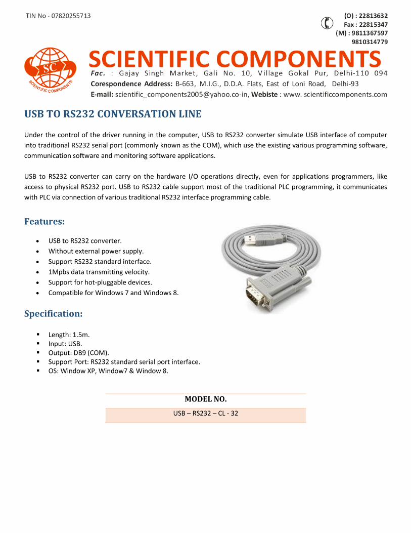
USB TO RS232 CONVERSATION LINE
Under the control of the driver running in the computer, USB to RS232 converter simulate USB interface of computer
into traditional RS232 serial port (commonly known as the COM), which use the existing various programming software,
communication software and monitoring software applications.
USB to RS232 converter can carry on the hardware I/O operations directly, even for applications programmers, like
access to physical RS232 port. USB to RS232 cable support most of the traditional PLC programming, it communicates
with PLC via connection of various traditional RS232 interface programming cable.
Features:
USB to RS232 converter.
Without external power supply.
Support RS232 standard interface.
1Mpbs data transmitting velocity.
Support for hot-pluggable devices.
Compatible for Windows 7 and Windows 8.
Specification:
Length: 1.5m. Input: USB. Output: DB9 (COM). Support Port: RS232 standard serial port interface. OS: Window XP, Window7 & Window 8.
MODEL NO.
USB – RS232 – CL - 32

OPTICS Optics constitutes general purpose optical components used in an optical experimental setups. The components
manufactured at World Technology include lenses, mirrors, beam splitters, prisms, filters, etc.
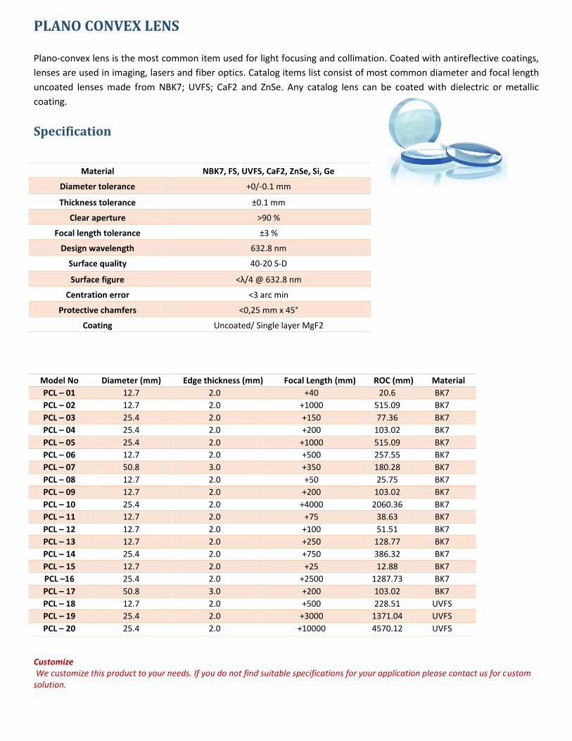
PLANO CONVEX LENS Plano-convex lens is the most common item used for light focusing and collimation. Coated with antireflective coatings,
lenses are used in imaging, lasers and fiber optics. Catalog items list consist of most common diameter and focal length
uncoated lenses made from NBK7; UVFS; CaF2 and ZnSe. Any catalog lens can be coated with dielectric or metallic
coating.
Specification
Customize We customize this product to your needs. If you do not find suitable specifications for your application please contact us for custom solution.
Material NBK7, FS, UVFS, CaF2, ZnSe, Si, Ge
Diameter tolerance +0/-0.1 mm
Thickness tolerance ±0.1 mm
Clear aperture >90 %
Focal length tolerance ±3 %
Design wavelength 632.8 nm
Surface quality 40-20 S-D
Surface figure <λ/4 @ 632.8 nm
Centration error <3 arc min
Protective chamfers <0,25 mm x 45°
Coating Uncoated/ Single layer MgF2
Model No Diameter (mm) Edge thickness (mm) Focal Length (mm) ROC (mm) Material
PCL – 01 12.7 2.0 +40 20.6 BK7
PCL – 02 12.7 2.0 +1000 515.09 BK7
PCL – 03 25.4 2.0 +150 77.36 BK7
PCL – 04 25.4 2.0 +200 103.02 BK7
PCL – 05 25.4 2.0 +1000 515.09 BK7
PCL – 06 12.7 2.0 +500 257.55 BK7
PCL – 07 50.8 3.0 +350 180.28 BK7
PCL – 08 12.7 2.0 +50 25.75 BK7
PCL – 09 12.7 2.0 +200 103.02 BK7
PCL – 10 25.4 2.0 +4000 2060.36 BK7
PCL – 11 12.7 2.0 +75 38.63 BK7
PCL – 12 12.7 2.0 +100 51.51 BK7
PCL – 13 12.7 2.0 +250 128.77 BK7
PCL – 14 25.4 2.0 +750 386.32 BK7
PCL – 15 12.7 2.0 +25 12.88 BK7
PCL –16 25.4 2.0 +2500 1287.73 BK7
PCL – 17 50.8 3.0 +200 103.02 BK7
PCL – 18 12.7 2.0 +500 228.51 UVFS
PCL – 19 25.4 2.0 +3000 1371.04 UVFS
PCL – 20 25.4 2.0 +10000 4570.12 UVFS
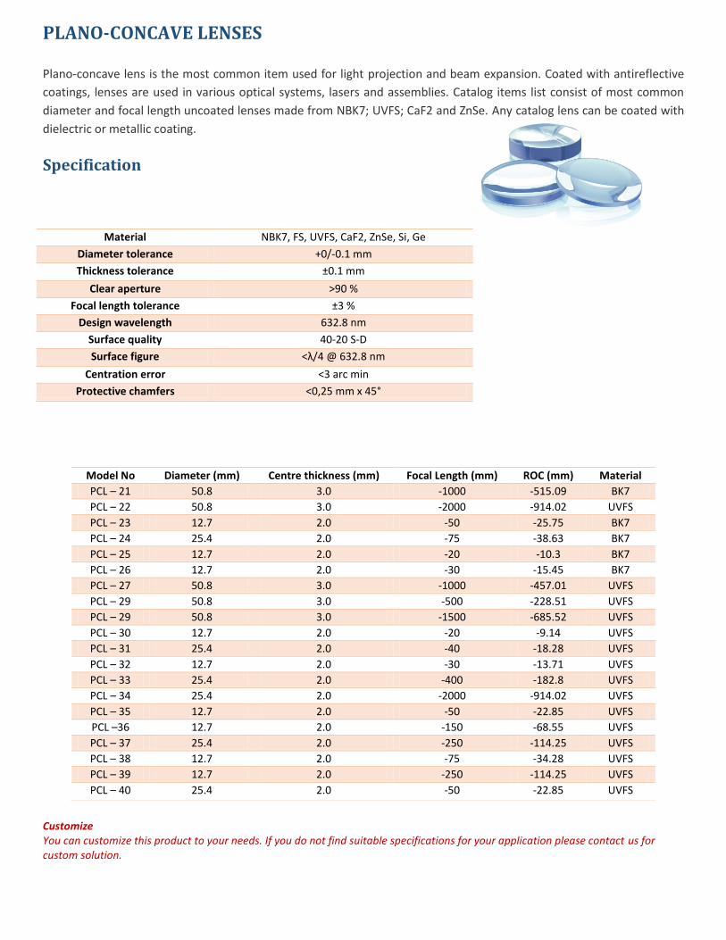
PLANO-CONCAVE LENSES Plano-concave lens is the most common item used for light projection and beam expansion. Coated with antireflective
coatings, lenses are used in various optical systems, lasers and assemblies. Catalog items list consist of most common
diameter and focal length uncoated lenses made from NBK7; UVFS; CaF2 and ZnSe. Any catalog lens can be coated with
dielectric or metallic coating.
Specification
Material NBK7, FS, UVFS, CaF2, ZnSe, Si, Ge
Diameter tolerance +0/-0.1 mm
Thickness tolerance ±0.1 mm
Clear aperture >90 %
Focal length tolerance ±3 %
Design wavelength 632.8 nm
Surface quality 40-20 S-D
Surface figure <λ/4 @ 632.8 nm
Centration error <3 arc min
Protective chamfers <0,25 mm x 45°
Customize You can customize this product to your needs. If you do not find suitable specifications for your application please contact us for custom solution.
Model No Diameter (mm) Centre thickness (mm) Focal Length (mm) ROC (mm) Material
PCL – 21 50.8 3.0 -1000 -515.09 BK7
PCL – 22 50.8 3.0 -2000 -914.02 UVFS
PCL – 23 12.7 2.0 -50 -25.75 BK7
PCL – 24 25.4 2.0 -75 -38.63 BK7
PCL – 25 12.7 2.0 -20 -10.3 BK7
PCL – 26 12.7 2.0 -30 -15.45 BK7
PCL – 27 50.8 3.0 -1000 -457.01 UVFS
PCL – 29 50.8 3.0 -500 -228.51 UVFS
PCL – 29 50.8 3.0 -1500 -685.52 UVFS
PCL – 30 12.7 2.0 -20 -9.14 UVFS
PCL – 31 25.4 2.0 -40 -18.28 UVFS
PCL – 32 12.7 2.0 -30 -13.71 UVFS
PCL – 33 25.4 2.0 -400 -182.8 UVFS
PCL – 34 25.4 2.0 -2000 -914.02 UVFS
PCL – 35 12.7 2.0 -50 -22.85 UVFS
PCL –36 12.7 2.0 -150 -68.55 UVFS
PCL – 37 25.4 2.0 -250 -114.25 UVFS
PCL – 38 12.7 2.0 -75 -34.28 UVFS
PCL – 39 12.7 2.0 -250 -114.25 UVFS
PCL – 40 25.4 2.0 -50 -22.85 UVFS
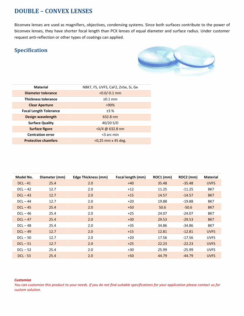
DOUBLE – CONVEX LENSES Biconvex lenses are used as magnifiers, objectives, condensing systems. Since both surfaces contribute to the power of
biconvex lenses, they have shorter focal length than PCX lenses of equal diameter and surface radius. Under customer
request anti-reflection or other types of coatings can applied.
Specification
Material NBK7, FS, UVFS, CaF2, ZnSe, Si, Ge
Diameter tolerance +0.0/-0.1 mm
Thickness tolerance ±0.1 mm
Clear Aperture >90%
Focal Length Tolerance ±3 %
Design wavelength 632.8 nm
Surface Quality 40/20 S/D
Surface figure <λ/4 @ 632.8 nm
Centration error <3 arc min
Protective chamfers <0,25 mm x 45 deg.
Model No. Diameter (mm) Edge Thickness (mm) Focal length (mm) ROC1 (mm) ROC2 (mm) Material
DCL - 41 25.4 2.0 +40 35.48 -35.48 UVFS
DCL – 42 12.7 2.0 +12 11.25 -11.25 BK7
DCL – 43 12.7 2.0 +15 14.57 -14.57 BK7
DCL – 44 12.7 2.0 +20 19.88 -19.88 BK7
DCL – 45 25.4 2.0 +50 50.6 -50.6 BK7
DCL – 46 25.4 2.0 +25 24.07 -24.07 BK7
DCL – 47 25.4 2.0 +30 29.53 -29.53 BK7
DCL – 48 25.4 2.0 +35 34.86 -34.86 BK7
DCL – 49 12.7 2.0 +15 12.81 -12.81 UVFS
DCL – 50 12.7 2.0 +20 17.56 -17.56 UVFS
DCL – 51 12.7 2.0 +25 22.23 -22.23 UVFS
DCL – 52 25.4 2.0 +30 25.99 -25.99 UVFS
DCL - 53 25.4 2.0 +50 44.79 -44.79 UVFS
Customize You can customize this product to your needs. If you do not find suitable specifications for your application please contact us for custom solution.
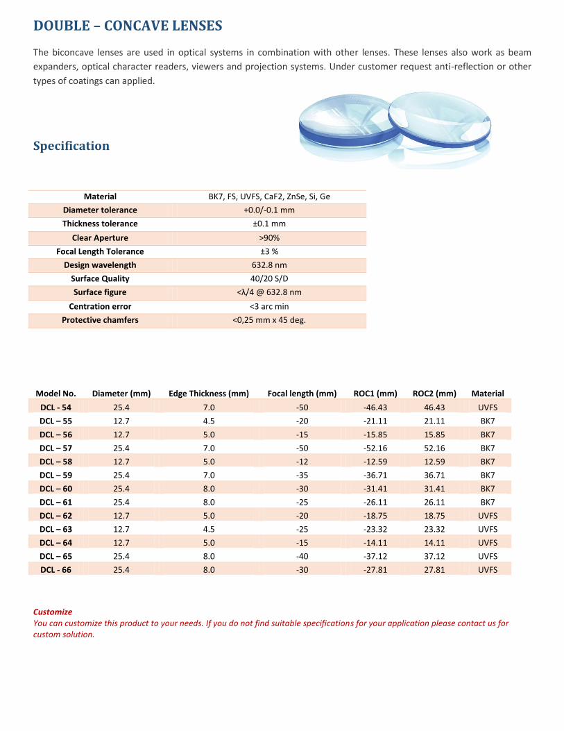
DOUBLE – CONCAVE LENSES The biconcave lenses are used in optical systems in combination with other lenses. These lenses also work as beam
expanders, optical character readers, viewers and projection systems. Under customer request anti-reflection or other
types of coatings can applied.
Specification
Material BK7, FS, UVFS, CaF2, ZnSe, Si, Ge
Diameter tolerance +0.0/-0.1 mm
Thickness tolerance ±0.1 mm
Clear Aperture >90%
Focal Length Tolerance ±3 %
Design wavelength 632.8 nm
Surface Quality 40/20 S/D
Surface figure <λ/4 @ 632.8 nm
Centration error <3 arc min
Protective chamfers <0,25 mm x 45 deg.
Model No. Diameter (mm) Edge Thickness (mm) Focal length (mm) ROC1 (mm) ROC2 (mm) Material
DCL - 54 25.4 7.0 -50 -46.43 46.43 UVFS
DCL – 55 12.7 4.5 -20 -21.11 21.11 BK7
DCL – 56 12.7 5.0 -15 -15.85 15.85 BK7
DCL – 57 25.4 7.0 -50 -52.16 52.16 BK7
DCL – 58 12.7 5.0 -12 -12.59 12.59 BK7
DCL – 59 25.4 7.0 -35 -36.71 36.71 BK7
DCL – 60 25.4 8.0 -30 -31.41 31.41 BK7
DCL – 61 25.4 8.0 -25 -26.11 26.11 BK7
DCL – 62 12.7 5.0 -20 -18.75 18.75 UVFS
DCL – 63 12.7 4.5 -25 -23.32 23.32 UVFS
DCL – 64 12.7 5.0 -15 -14.11 14.11 UVFS
DCL – 65 25.4 8.0 -40 -37.12 37.12 UVFS
DCL - 66 25.4 8.0 -30 -27.81 27.81 UVFS
Customize You can customize this product to your needs. If you do not find suitable specifications for your application please contact us for custom solution.
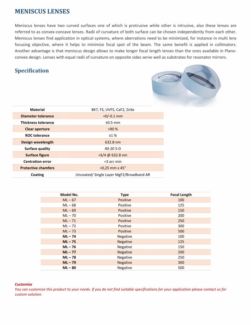
MENISCUS LENSES Meniscus lenses have two curved surfaces one of which is protrusive while other is intrusive, also these lenses are
referred to as convex-concave lenses. Radii of curvature of both surface can be chosen independently from each other.
Meniscus lenses find application in optical systems, where aberrations need to be minimized, for instance in multi lens
focusing objective, where it helps to minimize focal spot of the beam. The same benefit is applied in collimators.
Another advantage is that meniscus design allows to make longer focal length lenses than the ones available in Plano-
convex design. Lenses with equal radii of curvature on opposite sides serve well as substrates for resonator mirrors.
Specification
Material BK7, FS, UVFS, CaF2, ZnSe
Diameter tolerance +0/-0.1 mm
Thickness tolerance ±0.5 mm
Clear aperture >90 %
ROC tolerance ±1 %
Design wavelength 632.8 nm
Surface quality 40-20 S-D
Surface figure <λ/4 @ 632.8 nm
Centration error <3 arc min
Protective chamfers <0,25 mm x 45°
Coating Uncoated/ Single Layer MgF2/Broadband AR
Model No. Type Focal Length
ML – 67 Positive 100
ML – 68 Positive 125
ML – 69 Positive 150
ML – 70 Positive 200
ML – 71 Positive 250
ML – 72 Positive 300
ML – 73 Positive 500
ML – 74 Negative 100
ML – 75 Negative 125
ML – 76 Negative 150
ML – 77 Negative 200
ML – 78 Negative 250
ML – 79 Negative 300
ML – 80 Negative 500
Customize You can customize this product to your needs. If you do not find suitable specifications for your application please contact us for custom solution.
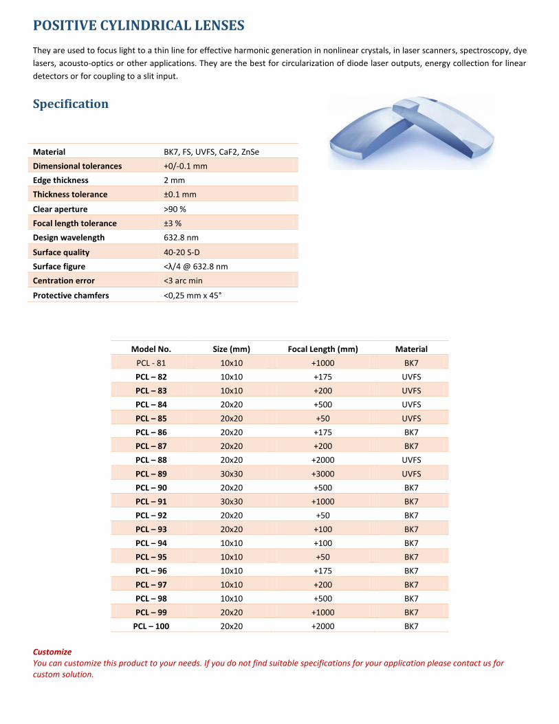
POSITIVE CYLINDRICAL LENSES They are used to focus light to a thin line for effective harmonic generation in nonlinear crystals, in laser scanners, spectroscopy, dye
lasers, acousto-optics or other applications. They are the best for circularization of diode laser outputs, energy collection for linear
detectors or for coupling to a slit input.
Specification
Material BK7, FS, UVFS, CaF2, ZnSe
Dimensional tolerances +0/-0.1 mm
Edge thickness 2 mm
Thickness tolerance ±0.1 mm
Clear aperture >90 %
Focal length tolerance ±3 %
Design wavelength 632.8 nm
Surface quality 40-20 S-D
Surface figure <λ/4 @ 632.8 nm
Centration error <3 arc min
Protective chamfers <0,25 mm x 45°
Model No. Size (mm) Focal Length (mm) Material
PCL - 81 10x10 +1000 BK7
PCL – 82 10x10 +175 UVFS
PCL – 83 10x10 +200 UVFS
PCL – 84 20x20 +500 UVFS
PCL – 85 20x20 +50 UVFS
PCL – 86 20x20 +175 BK7
PCL – 87 20x20 +200 BK7
PCL – 88 20x20 +2000 UVFS
PCL – 89 30x30 +3000 UVFS
PCL – 90 20x20 +500 BK7
PCL – 91 30x30 +1000 BK7
PCL – 92 20x20 +50 BK7
PCL – 93 20x20 +100 BK7
PCL – 94 10x10 +100 BK7
PCL – 95 10x10 +50 BK7
PCL – 96 10x10 +175 BK7
PCL – 97 10x10 +200 BK7
PCL – 98 10x10 +500 BK7
PCL – 99 20x20 +1000 BK7
PCL – 100 20x20 +2000 BK7
Customize You can customize this product to your needs. If you do not find suitable specifications for your application please contact us for custom solution.
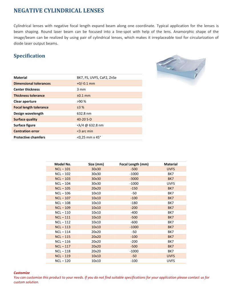
NEGATIVE CYLINDRICAL LENSES
Cylindrical lenses with negative focal length expand beam along one coordinate. Typical application for the lenses is
beam shaping. Round laser beam can be focused into a line-spot with help of the lens. Anamorphic shape of the
image/beam can be realized by using pair of cylindrical lenses, which makes it irreplaceable tool for circularization of
diode laser output beams.
Specification
Material BK7, FS, UVFS, CaF2, ZnSe
Dimensional tolerances +0/-0.1 mm
Center thickness 3 mm
Thickness tolerance ±0.1 mm
Clear aperture >90 %
Focal length tolerance ±3 %
Design wavelength 632.8 nm
Surface quality 40-20 S-D
Surface figure <λ/4 @ 632.8 nm
Centration error <3 arc min
Protective chamfers <0,25 mm x 45°
Model No. Size (mm) Focal Length (mm) Material
NCL – 101 30x30 -500 UVFS
NCL – 102 30x30 -1000 BK7
NCL – 103 30x30 -3000 BK7
NCL – 104 30x30 -1000 UVFS
NCL – 105 20x20 -150 BK7
NCL – 106 10x10 -50 BK7
NCL – 107 10x10 -100 BK7
NCL – 108 10x10 -180 BK7
NCL – 109 10x10 -200 BK7
NCL – 110 10x10 -400 BK7
NCL – 111 10x10 -500 BK7
NCL – 112 10x10 -600 BK7
NCL – 113 10x10 -1000 BK7
NCL – 114 20x20 -50 BK7
NCL – 115 20x20 -100 BK7
NCL – 116 20x20 -200 BK7
NCL – 117 20x20 -500 BK7
NCL – 118 20x20 -1000 BK7
NCL – 119 10x10 -50 UVFS
NCL – 120 10x10 -100 UVFS
Customize You can customize this product to your needs. If you do not find suitable specifications for your application please contact us for custom solution.
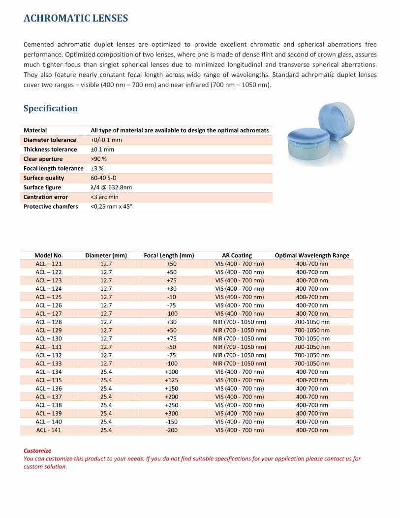
ACHROMATIC LENSES
Cemented achromatic duplet lenses are optimized to provide excellent chromatic and spherical aberrations free
performance. Optimized composition of two lenses, where one is made of dense flint and second of crown glass, assures
much tighter focus than singlet spherical lenses due to minimized longitudinal and transverse spherical aberrations.
They also feature nearly constant focal length across wide range of wavelengths. Standard achromatic duplet lenses
cover two ranges – visible (400 nm – 700 nm) and near infrared (700 nm – 1050 nm).
Specification
Model No. Diameter (mm) Focal Length (mm) AR Coating Optimal Wavelength Range
ACL – 121 12.7 +50 VIS (400 - 700 nm) 400-700 nm
ACL – 122 12.7 +50 VIS (400 - 700 nm) 400-700 nm
ACL – 123 12.7 +75 VIS (400 - 700 nm) 400-700 nm
ACL – 124 12.7 +30 VIS (400 - 700 nm) 400-700 nm
ACL – 125 12.7 -50 VIS (400 - 700 nm) 400-700 nm
ACL – 126 12.7 -75 VIS (400 - 700 nm) 400-700 nm
ACL – 127 12.7 -100 VIS (400 - 700 nm) 400-700 nm
ACL – 128 12.7 +30 NIR (700 - 1050 nm) 700-1050 nm
ACL – 129 12.7 +50 NIR (700 - 1050 nm) 700-1050 nm
ACL – 130 12.7 +75 NIR (700 - 1050 nm) 700-1050 nm
ACL – 131 12.7 -50 NIR (700 - 1050 nm) 700-1050 nm
ACL – 132 12.7 -75 NIR (700 - 1050 nm) 700-1050 nm
ACL – 133 12.7 -100 NIR (700 - 1050 nm) 700-1050 nm
ACL – 134 25.4 +100 VIS (400 - 700 nm) 400-700 nm
ACL – 135 25.4 +125 VIS (400 - 700 nm) 400-700 nm
ACL – 136 25.4 +150 VIS (400 - 700 nm) 400-700 nm
ACL – 137 25.4 +200 VIS (400 - 700 nm) 400-700 nm
ACL – 138 25.4 +250 VIS (400 - 700 nm) 400-700 nm
ACL – 139 25.4 +300 VIS (400 - 700 nm) 400-700 nm
ACL – 140 25.4 -150 VIS (400 - 700 nm) 400-700 nm
ACL - 141 25.4 -200 VIS (400 - 700 nm) 400-700 nm
Customize You can customize this product to your needs. If you do not find suitable specifications for your application please contact us for custom solution.
Material All type of material are available to design the optimal achromats
Diameter tolerance +0/-0.1 mm
Thickness tolerance ±0.1 mm
Clear aperture >90 %
Focal length tolerance ±3 %
Surface quality 60-40 S-D
Surface figure λ/4 @ 632.8nm
Centration error <3 arc min
Protective chamfers <0,25 mm x 45°
javascript:SetFilterValue('NIR%20(700%20-%201050%20nm)','catalog-filter-box2','catalog-filter-box2')
javascript:SetFilterValue('NIR%20(700%20-%201050%20nm)','catalog-filter-box2','catalog-filter-box2')
javascript:SetFilterValue('NIR%20(700%20-%201050%20nm)','catalog-filter-box2','catalog-filter-box2')
javascript:SetFilterValue('NIR%20(700%20-%201050%20nm)','catalog-filter-box2','catalog-filter-box2')
javascript:SetFilterValue('NIR%20(700%20-%201050%20nm)','catalog-filter-box2','catalog-filter-box2')
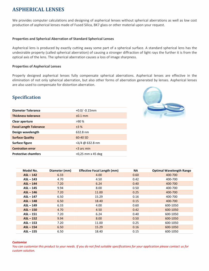
ASPHERICAL LENSES We provides computer calculations and designing of aspherical lenses without spherical aberrations as well as low cost production of aspherical lenses made of Fused Silica, BK7 glass or other material upon your request. Properties and Spherical Aberration of Standard Spherical Lenses Aspherical lens is produced by exactly cutting away some part of a spherical surface. A standard spherical lens has the undesirable property (called spherical aberration) of causing a stronger diffraction of light rays the further it is from the optical axis of the lens. The spherical aberration causes a loss of image sharpness. Properties of Aspherical Lenses Properly designed aspherical lenses fully compensate spherical aberrations. Aspherical lenses are effective in the elimination of not only spherical aberration, but also other forms of aberration generated by lenses. Aspherical lenses are also used to compensate for distortion aberration.
Specification
Diameter Tolerance +0.0/ -0.15mm
Thickness tolerance ±0.1 mm
Clear aperture >90 %
Focal Length Tolerance ±3 %
Design wavelength 632.8 nm
Surface Quality 60-40 SD
Surface figure <λ/4 @ 632.8 nm
Centration error <3 arc min
Protective chamfers <0,25 mm x 45 deg
Model No. Diameter (mm) Effective Focal Length (mm) NA Optimal Wavelength Range
ASL – 142 6.33 4.00 0.60 400-700
ASL – 143 4.70 4.50 0.42 400-700
ASL – 144 7.20 6.24 0.40 400-700
ASL – 145 9.94 8.00 0.50 400-700
ASL – 146 7.20 11.00 0.25 400-700
ASL – 147 6.50 15.29 0.16 400-700
ASL – 148 6.50 18.40 0.15 400-700
ASL – 149 6.33 4.00 0.60 600-1050
ASL – 150 4.70 4.50 0.42 600-1050
ASL – 151 7.20 6.24 0.40 600-1050
ASL – 152 9.94 8.00 0.50 600-1050
ASL – 153 7.20 11.00 0.25 600-1050
ASL – 154 6.50 15.29 0.16 600-1050
ASL – 155 6.50 18.40 0.15 600-1050
Customize You can customize this product to your needs. If you do not find suitable specifications for your application please contact us for custom solution.
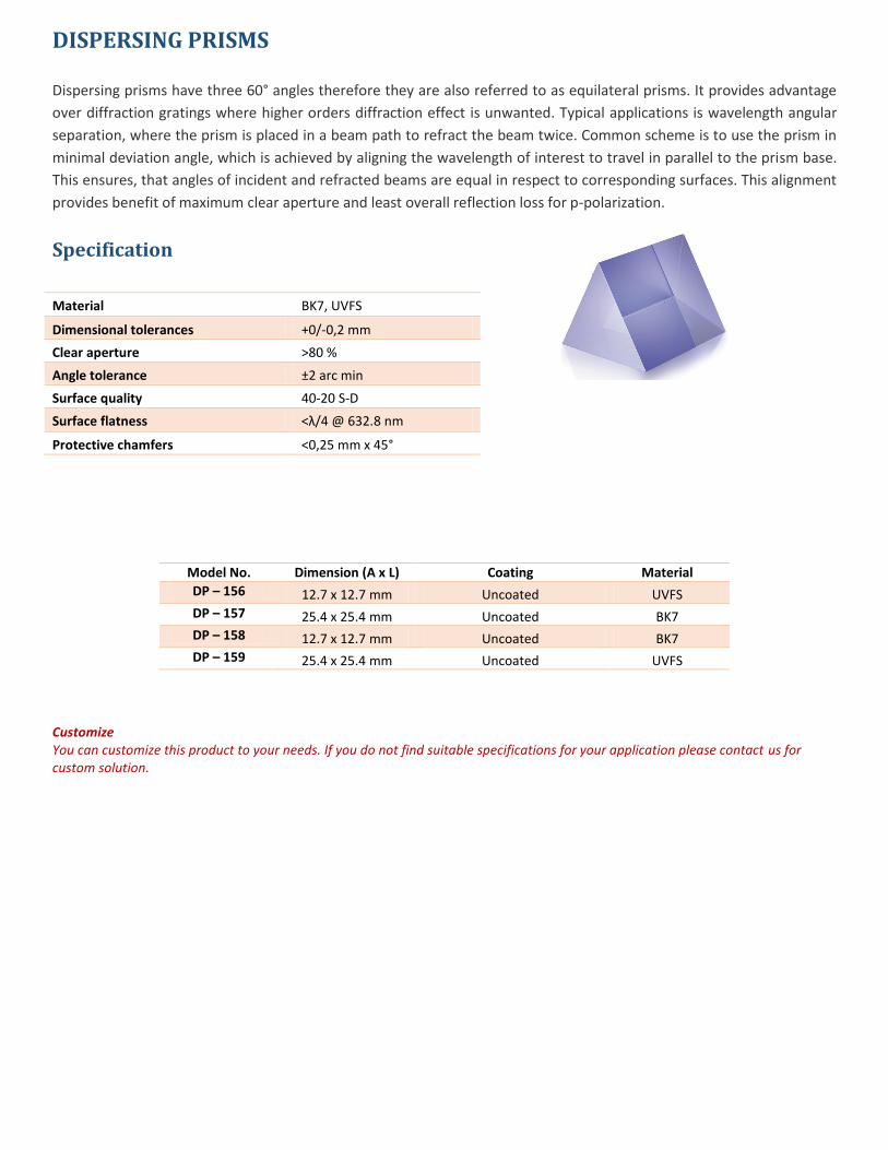
DISPERSING PRISMS Dispersing prisms have three 60° angles therefore they are also referred to as equilateral prisms. It provides advantage
over diffraction gratings where higher orders diffraction effect is unwanted. Typical applications is wavelength angular
separation, where the prism is placed in a beam path to refract the beam twice. Common scheme is to use the prism in
minimal deviation angle, which is achieved by aligning the wavelength of interest to travel in parallel to the prism base.
This ensures, that angles of incident and refracted beams are equal in respect to corresponding surfaces. This alignment
provides benefit of maximum clear aperture and least overall reflection loss for p-polarization.
Specification
Material BK7, UVFS
Dimensional tolerances +0/-0,2 mm
Clear aperture >80 %
Angle tolerance ±2 arc min
Surface quality 40-20 S-D
Surface flatness <λ/4 @ 632.8 nm
Protective chamfers <0,25 mm x 45°
Model No. Dimension (A x L) Coating Material
DP – 156 12.7 x 12.7 mm Uncoated UVFS
DP – 157 25.4 x 25.4 mm Uncoated BK7
DP – 158 12.7 x 12.7 mm Uncoated BK7
DP – 159 25.4 x 25.4 mm Uncoated UVFS
Customize You can customize this product to your needs. If you do not find suitable specifications for your application please contact us for custom solution.
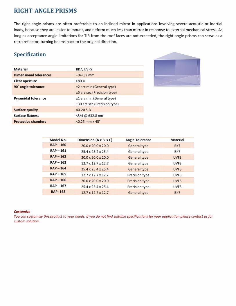
RIGHT-ANGLE PRISMS
The right angle prisms are often preferable to an inclined mirror in applications involving severe acoustic or inertial
loads, because they are easier to mount, and deform much less than mirror in response to external mechanical stress. As
long as acceptance angle limitations for TIR from the roof faces are not exceeded, the right angle prisms can serve as a
retro reflector, turning beams back to the original direction.
Specification
Material BK7, UVFS
Dimensional tolerances +0/-0,2 mm
Clear aperture >80 %
90˚ angle tolerance ±2 arc min (General type)
±5 arc sec (Precision type)
Pyramidal tolerance ±1 arc min (General type)
±30 arc sec (Precision type)
Surface quality 40-20 S-D
Surface flatness <λ/4 @ 632.8 nm
Protective chamfers <0,25 mm x 45°
Model No. Dimension (A x B x C) Angle Tolerance Material
RAP – 160 20.0 x 20.0 x 20.0 General type BK7
RAP – 161 25.4 x 25.4 x 25.4 General type BK7
RAP – 162 20.0 x 20.0 x 20.0 General type UVFS
RAP – 163 12.7 x 12.7 x 12.7 General type UVFS
RAP – 164 25.4 x 25.4 x 25.4 General type UVFS
RAP – 165 12.7 x 12.7 x 12.7 Precision type UVFS
RAP – 166 20.0 x 20.0 x 20.0 Precision type UVFS
RAP – 167 25.4 x 25.4 x 25.4 Precision type UVFS
RAP- 168 12.7 x 12.7 x 12.7 General type BK7
Customize You can customize this product to your needs. If you do not find suitable specifications for your application please contact us for custom solution.
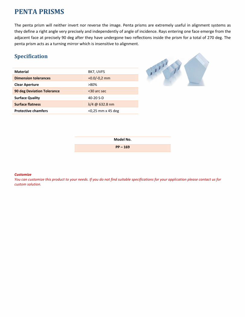
PENTA PRISMS
The penta prism will neither invert nor reverse the image. Penta prisms are extremely useful in alignment systems as
they define a right angle very precisely and independently of angle of incidence. Rays entering one face emerge from the
adjacent face at precisely 90 deg after they have undergone two reflections inside the prism for a total of 270 deg. The
penta prism acts as a turning mirror which is insensitive to alignment.
Specification
Material BK7, UVFS
Dimension tolerances +0.0/-0,2 mm
Clear Aperture >80%
90 deg Deviation Tolerance <30 arc sec
Surface Quality 40-20 S-D
Surface flatness λ/4 @ 632.8 nm
Protective chamfers <0,25 mm x 45 deg
Model No.
PP – 169
Customize You can customize this product to your needs. If you do not find suitable specifications for your application please contact us for custom solution.
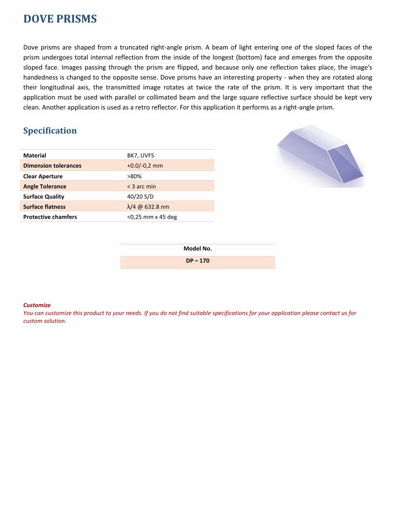
DOVE PRISMS
Dove prisms are shaped from a truncated right-angle prism. A beam of light entering one of the sloped faces of the
prism undergoes total internal reflection from the inside of the longest (bottom) face and emerges from the opposite
sloped face. Images passing through the prism are flipped, and because only one reflection takes place, the image's
handedness is changed to the opposite sense. Dove prisms have an interesting property - when they are rotated along
their longitudinal axis, the transmitted image rotates at twice the rate of the prism. It is very important that the
application must be used with parallel or collimated beam and the large square reflective surface should be kept very
clean. Another application is used as a retro reflector. For this application it performs as a right-angle prism.
Specification
Material BK7, UVFS
Dimension tolerances +0.0/-0,2 mm
Clear Aperture >80%
Angle Tolerance < 3 arc min
Surface Quality 40/20 S/D
Surface flatness λ/4 @ 632.8 nm
Protective chamfers <0,25 mm x 45 deg
Model No.
DP – 170
Customize You can customize this product to your needs. If you do not find suitable specifications for your application please contact us for custom solution.
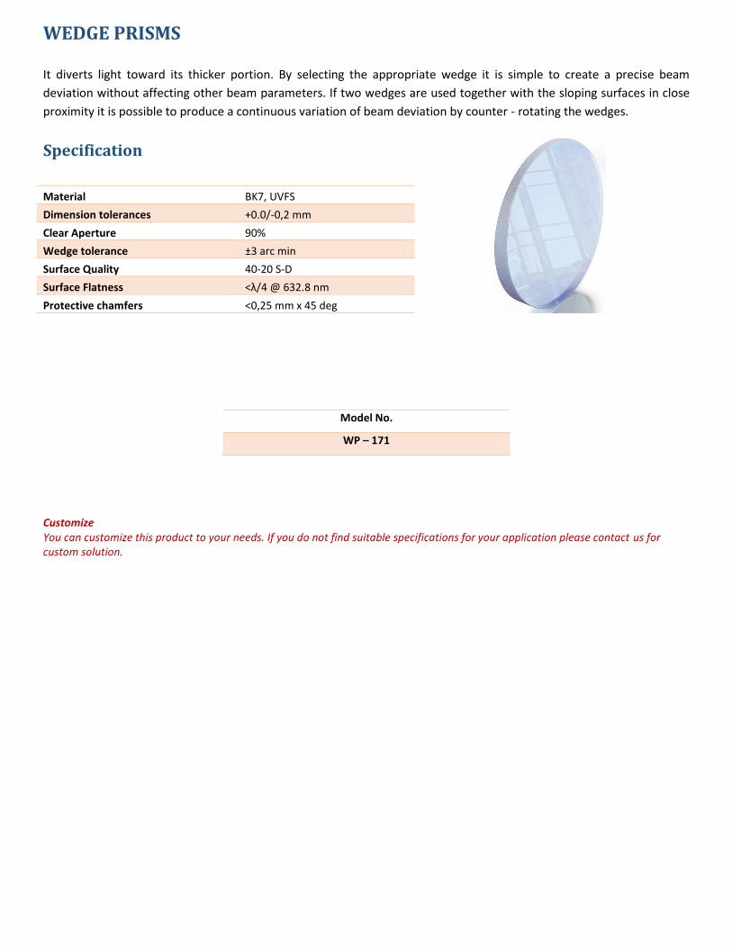
WEDGE PRISMS It diverts light toward its thicker portion. By selecting the appropriate wedge it is simple to create a precise beam
deviation without affecting other beam parameters. If two wedges are used together with the sloping surfaces in close
proximity it is possible to produce a continuous variation of beam deviation by counter - rotating the wedges.
Specification
Material BK7, UVFS
Dimension tolerances +0.0/-0,2 mm
Clear Aperture 90%
Wedge tolerance ±3 arc min
Surface Quality 40-20 S-D
Surface Flatness <λ/4 @ 632.8 nm
Protective chamfers <0,25 mm x 45 deg
Model No.
WP – 171
Customize You can customize this product to your needs. If you do not find suitable specifications for your application please contact us for custom solution.
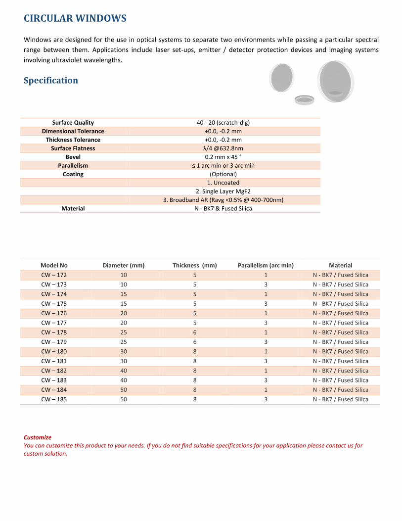
CIRCULAR WINDOWS
Windows are designed for the use in optical systems to separate two environments while passing a particular spectral
range between them. Applications include laser set-ups, emitter / detector protection devices and imaging systems
involving ultraviolet wavelengths.
Specification
Surface Quality 40 - 20 (scratch-dig)
Dimensional Tolerance +0.0, -0.2 mm
Thickness Tolerance +0.0, -0.2 mm
Surface Flatness λ/4 @632.8nm
Bevel 0.2 mm x 45 °
Parallelism ≤ 1 arc min or 3 arc min
Coating (Optional)
1. Uncoated
2. Single Layer MgF2
3. Broadband AR (Ravg <0.5% @ 400-700nm)
Material N - BK7 & Fused Silica
Model No Diameter (mm) Thickness (mm) Parallelism (arc min) Material
CW – 172 10 5 1 N - BK7 / Fused Silica
CW – 173 10 5 3 N - BK7 / Fused Silica
CW – 174 15 5 1 N - BK7 / Fused Silica
CW – 175 15 5 3 N - BK7 / Fused Silica
CW – 176 20 5 1 N - BK7 / Fused Silica
CW – 177 20 5 3 N - BK7 / Fused Silica
CW – 178 25 6 1 N - BK7 / Fused Silica
CW – 179 25 6 3 N - BK7 / Fused Silica
CW – 180 30 8 1 N - BK7 / Fused Silica
CW – 181 30 8 3 N - BK7 / Fused Silica
CW – 182 40 8 1 N - BK7 / Fused Silica
CW – 183 40 8 3 N - BK7 / Fused Silica
CW – 184 50 8 1 N - BK7 / Fused Silica
CW – 185 50 8 3 N - BK7 / Fused Silica
Customize You can customize this product to your needs. If you do not find suitable specifications for your application please contact us for custom solution.
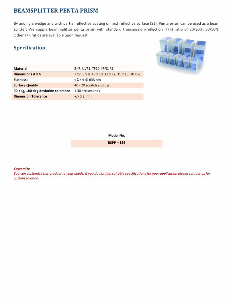
BEAMSPLITTER PENTA PRISM
By adding a wedge and with partial reflective coating on first reflective surface (S1), Penta prism can be used as a beam
splitter. We supply beam splitter penta prism with standard transmission/reflection (T/R) ratio of 20/80%, 50/50%.
Other T/R ratios are available upon request.
Specification
Material BK7, UVFS, TF10, IRFS, FS
Dimensions A x h 7 x7, 8 x 8, 10 x 10, 12 x 12, 15 x 15, 20 x 20
Flatness: < λ / 4 @ 633 nm
Surface Quality 40 - 20 scratch and dig
90 deg, 180 deg deviation tolerance < 30 arc seconds
Dimension Tolerance +/- 0.2 mm
Model No.
BSPP – 186
Customize You can customize this product to your needs. If you do not find suitable specifications for your application please contact us for custom solution.
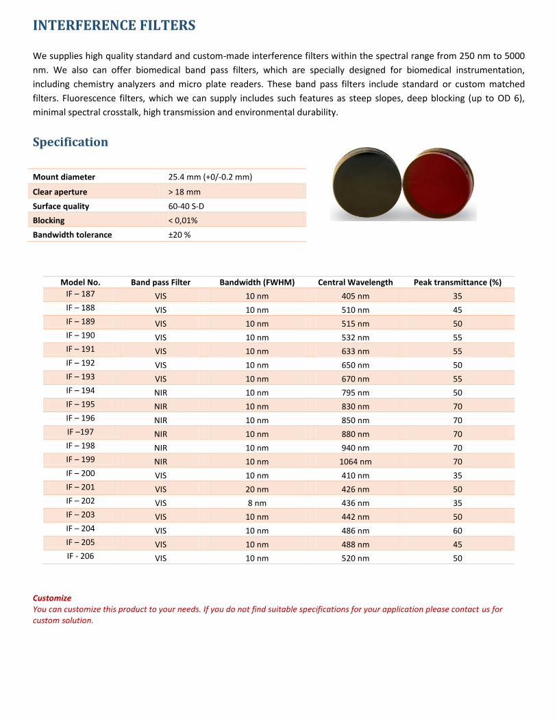
INTERFERENCE FILTERS
We supplies high quality standard and custom-made interference filters within the spectral range from 250 nm to 5000
nm. We also can offer biomedical band pass filters, which are specially designed for biomedical instrumentation,
including chemistry analyzers and micro plate readers. These band pass filters include standard or custom matched
filters. Fluorescence filters, which we can supply includes such features as steep slopes, deep blocking (up to OD 6),
minimal spectral crosstalk, high transmission and environmental durability.
Specification
Mount diameter 25.4 mm (+0/-0.2 mm)
Clear aperture > 18 mm
Surface quality 60-40 S-D
Blocking < 0,01%
Bandwidth tolerance ±20 %
Model No. Band pass Filter Bandwidth (FWHM) Central Wavelength Peak transmittance (%)
IF – 187 VIS 10 nm 405 nm 35
IF – 188 VIS 10 nm 510 nm 45
IF – 189 VIS 10 nm 515 nm 50
IF – 190 VIS 10 nm 532 nm 55
IF – 191 VIS 10 nm 633 nm 55
IF – 192 VIS 10 nm 650 nm 50
IF – 193 VIS 10 nm 670 nm 55
IF – 194 NIR 10 nm 795 nm 50
IF – 195 NIR 10 nm 830 nm 70
IF – 196 NIR 10 nm 850 nm 70
IF –197 NIR 10 nm 880 nm 70
IF – 198 NIR 10 nm 940 nm 70
IF – 199 NIR 10 nm 1064 nm 70
IF – 200 VIS 10 nm 410 nm 35
IF – 201 VIS 20 nm 426 nm 50
IF – 202 VIS 8 nm 436 nm 35
IF – 203 VIS 10 nm 442 nm 50
IF – 204 VIS 10 nm 486 nm 60
IF – 205 VIS 10 nm 488 nm 45
IF - 206 VIS 10 nm 520 nm 50
Customize You can customize this product to your needs. If you do not find suitable specifications for your application please contact us for custom solution.
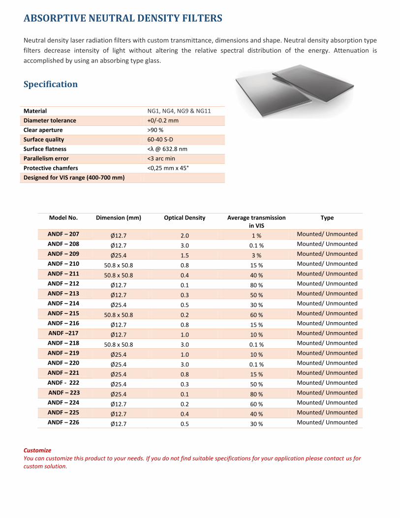
ABSORPTIVE NEUTRAL DENSITY FILTERS
Neutral density laser radiation filters with custom transmittance, dimensions and shape. Neutral density absorption type
filters decrease intensity of light without altering the relative spectral distribution of the energy. Attenuation is
accomplished by using an absorbing type glass.
Specification
Material NG1, NG4, NG9 & NG11
Diameter tolerance +0/-0.2 mm
Clear aperture >90 %
Surface quality 60-40 S-D
Surface flatness <λ @ 632.8 nm
Parallelism error <3 arc min
Protective chamfers <0,25 mm x 45°
Designed for VIS range (400-700 mm)
Model No. Dimension (mm) Optical Density Average transmission in VIS
Type
ANDF – 207 Ø12.7 2.0 1 % Mounted/ Unmounted
ANDF – 208 Ø12.7 3.0 0.1 % Mounted/ Unmounted
ANDF – 209 Ø25.4 1.5 3 % Mounted/ Unmounted
ANDF – 210 50.8 x 50.8 0.8 15 % Mounted/ Unmounted
ANDF – 211 50.8 x 50.8 0.4 40 % Mounted/ Unmounted
ANDF – 212 Ø12.7 0.1 80 % Mounted/ Unmounted
ANDF – 213 Ø12.7 0.3 50 % Mounted/ Unmounted
ANDF – 214 Ø25.4 0.5 30 % Mounted/ Unmounted
ANDF – 215 50.8 x 50.8 0.2 60 % Mounted/ Unmounted
ANDF – 216 Ø12.7 0.8 15 % Mounted/ Unmounted
ANDF –217 Ø12.7 1.0 10 % Mounted/ Unmounted
ANDF – 218 50.8 x 50.8 3.0 0.1 % Mounted/ Unmounted
ANDF – 219 Ø25.4 1.0 10 % Mounted/ Unmounted
ANDF – 220 Ø25.4 3.0 0.1 % Mounted/ Unmounted
ANDF – 221 Ø25.4 0.8 15 % Mounted/ Unmounted
ANDF - 222 Ø25.4 0.3 50 % Mounted/ Unmounted
ANDF – 223 Ø25.4 0.1 80 % Mounted/ Unmounted
ANDF – 224 Ø12.7 0.2 60 % Mounted/ Unmounted
ANDF – 225 Ø12.7 0.4 40 % Mounted/ Unmounted
ANDF – 226 Ø12.7 0.5 30 % Mounted/ Unmounted
Customize You can customize this product to your needs. If you do not find suitable specifications for your application please contact us for custom solution.
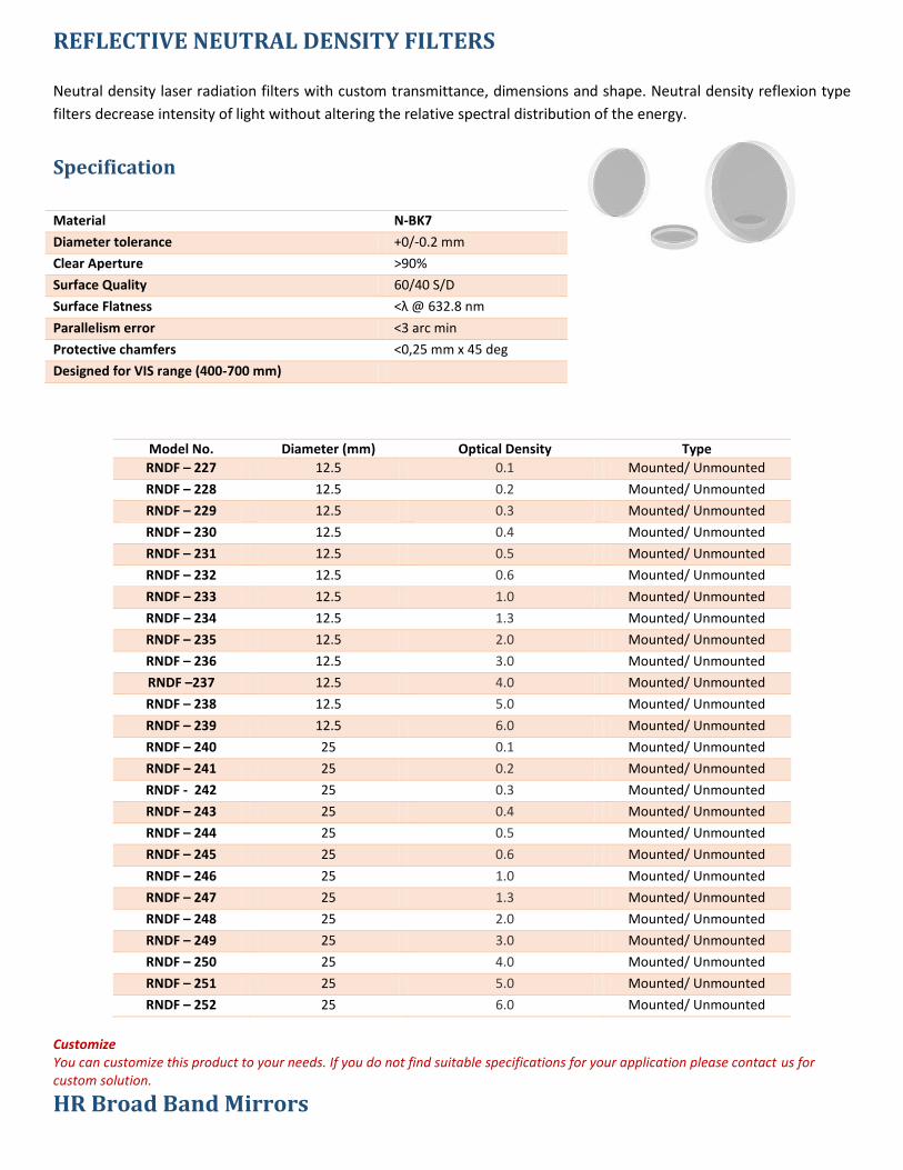
REFLECTIVE NEUTRAL DENSITY FILTERS
Neutral density laser radiation filters with custom transmittance, dimensions and shape. Neutral density reflexion type
filters decrease intensity of light without altering the relative spectral distribution of the energy.
Specification
Material N-BK7
Diameter tolerance +0/-0.2 mm
Clear Aperture >90%
Surface Quality 60/40 S/D
Surface Flatness <λ @ 632.8 nm
Parallelism error <3 arc min
Protective chamfers <0,25 mm x 45 deg
Designed for VIS range (400-700 mm)
Model No. Diameter (mm) Optical Density Type
RNDF – 227 12.5 0.1 Mounted/ Unmounted
RNDF – 228 12.5 0.2 Mounted/ Unmounted
RNDF – 229 12.5 0.3 Mounted/ Unmounted
RNDF – 230 12.5 0.4 Mounted/ Unmounted
RNDF – 231 12.5 0.5 Mounted/ Unmounted
RNDF – 232 12.5 0.6 Mounted/ Unmounted
RNDF – 233 12.5 1.0 Mounted/ Unmounted
RNDF – 234 12.5 1.3 Mounted/ Unmounted
RNDF – 235 12.5 2.0 Mounted/ Unmounted
RNDF – 236 12.5 3.0 Mounted/ Unmounted
RNDF –237 12.5 4.0 Mounted/ Unmounted
RNDF – 238 12.5 5.0 Mounted/ Unmounted
RNDF – 239 12.5 6.0 Mounted/ Unmounted
RNDF – 240 25 0.1 Mounted/ Unmounted
RNDF – 241 25 0.2 Mounted/ Unmounted
RNDF - 242 25 0.3 Mounted/ Unmounted
RNDF – 243 25 0.4 Mounted/ Unmounted
RNDF – 244 25 0.5 Mounted/ Unmounted
RNDF – 245 25 0.6 Mounted/ Unmounted
RNDF – 246 25 1.0 Mounted/ Unmounted
RNDF – 247 25 1.3 Mounted/ Unmounted
RNDF – 248 25 2.0 Mounted/ Unmounted
RNDF – 249 25 3.0 Mounted/ Unmounted
RNDF – 250 25 4.0 Mounted/ Unmounted
RNDF – 251 25 5.0 Mounted/ Unmounted
RNDF – 252 25 6.0 Mounted/ Unmounted
Customize You can customize this product to your needs. If you do not find suitable specifications for your application please contact us for custom solution.
HR Broad Band Mirrors
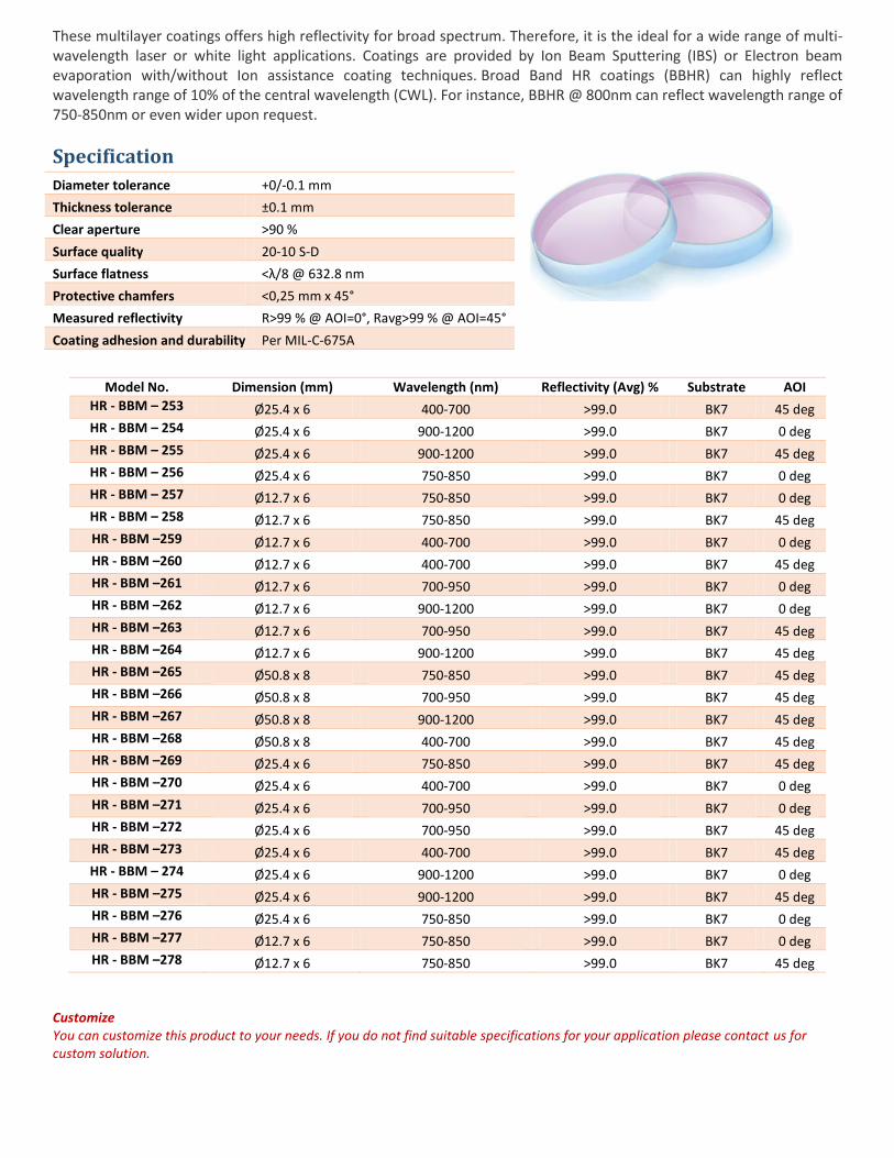
These multilayer coatings offers high reflectivity for broad spectrum. Therefore, it is the ideal for a wide range of multi-wavelength laser or white light applications. Coatings are provided by Ion Beam Sputtering (IBS) or Electron beam evaporation with/without Ion assistance coating techniques. Broad Band HR coatings (BBHR) can highly reflect wavelength range of 10% of the central wavelength (CWL). For instance, BBHR @ 800nm can reflect wavelength range of 750-850nm or even wider upon request.
Specification
Diameter tolerance +0/-0.1 mm
Thickness tolerance ±0.1 mm
Clear aperture >90 %
Surface quality 20-10 S-D
Surface flatness <λ/8 @ 632.8 nm
Protective chamfers <0,25 mm x 45°
Measured reflectivity R>99 % @ AOI=0°, Ravg>99 % @ AOI=45°
Coating adhesion and durability Per MIL-C-675A
Model No. Dimension (mm) Wavelength (nm) Reflectivity (Avg) % Substrate AOI
HR - BBM – 253 Ø25.4 x 6 400-700 >99.0 BK7 45 deg
HR - BBM – 254 Ø25.4 x 6 900-1200 >99.0 BK7 0 deg
HR - BBM – 255 Ø25.4 x 6 900-1200 >99.0 BK7 45 deg
HR - BBM – 256 Ø25.4 x 6 750-850 >99.0 BK7 0 deg
HR - BBM – 257 Ø12.7 x 6 750-850 >99.0 BK7 0 deg
HR - BBM – 258 Ø12.7 x 6 750-850 >99.0 BK7 45 deg
HR - BBM –259 Ø12.7 x 6 400-700 >99.0 BK7 0 deg
HR - BBM –260 Ø12.7 x 6 400-700 >99.0 BK7 45 deg
HR - BBM –261 Ø12.7 x 6 700-950 >99.0 BK7 0 deg
HR - BBM –262 Ø12.7 x 6 900-1200 >99.0 BK7 0 deg
HR - BBM –263 Ø12.7 x 6 700-950 >99.0 BK7 45 deg
HR - BBM –264 Ø12.7 x 6 900-1200 >99.0 BK7 45 deg
HR - BBM –265 Ø50.8 x 8 750-850 >99.0 BK7 45 deg
HR - BBM –266 Ø50.8 x 8 700-950 >99.0 BK7 45 deg
HR - BBM –267 Ø50.8 x 8 900-1200 >99.0 BK7 45 deg
HR - BBM –268 Ø50.8 x 8 400-700 >99.0 BK7 45 deg
HR - BBM –269 Ø25.4 x 6 750-850 >99.0 BK7 45 deg
HR - BBM –270 Ø25.4 x 6 400-700 >99.0 BK7 0 deg
HR - BBM –271 Ø25.4 x 6 700-950 >99.0 BK7 0 deg
HR - BBM –272 Ø25.4 x 6 700-950 >99.0 BK7 45 deg
HR - BBM –273 Ø25.4 x 6 400-700 >99.0 BK7 45 deg
HR - BBM – 274 Ø25.4 x 6 900-1200 >99.0 BK7 0 deg
HR - BBM –275 Ø25.4 x 6 900-1200 >99.0 BK7 45 deg
HR - BBM –276 Ø25.4 x 6 750-850 >99.0 BK7 0 deg
HR - BBM –277 Ø12.7 x 6 750-850 >99.0 BK7 0 deg
HR - BBM –278 Ø12.7 x 6 750-850 >99.0 BK7 45 deg
Customize You can customize this product to your needs. If you do not find suitable specifications for your application please contact us for custom solution.
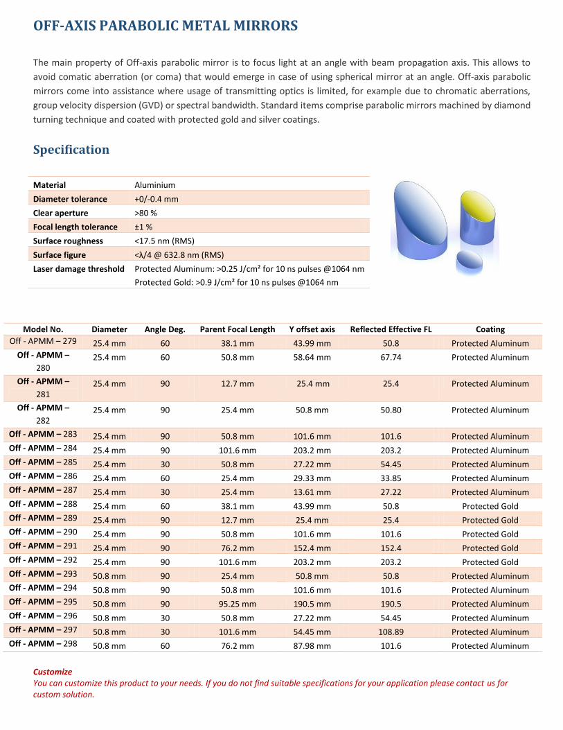
OFF-AXIS PARABOLIC METAL MIRRORS
The main property of Off-axis parabolic mirror is to focus light at an angle with beam propagation axis. This allows to
avoid comatic aberration (or coma) that would emerge in case of using spherical mirror at an angle. Off-axis parabolic
mirrors come into assistance where usage of transmitting optics is limited, for example due to chromatic aberrations,
group velocity dispersion (GVD) or spectral bandwidth. Standard items comprise parabolic mirrors machined by diamond
turning technique and coated with protected gold and silver coatings.
Specification
Material Aluminium
Diameter tolerance +0/-0.4 mm
Clear aperture >80 %
Focal length tolerance ±1 %
Surface roughness <17.5 nm (RMS)
Surface figure <λ/4 @ 632.8 nm (RMS)
Laser damage threshold Protected Aluminum: >0.25 J/cm² for 10 ns pulses @1064 nm
Protected Gold: >0.9 J/cm² for 10 ns pulses @1064 nm
Model No. Diameter Angle Deg. Parent Focal Length Y offset axis Reflected Effective FL Coating
Off - APMM – 279 25.4 mm 60 38.1 mm 43.99 mm 50.8 Protected Aluminum
Off - APMM –
280 25.4 mm 60 50.8 mm 58.64 mm 67.74 Protected Aluminum
Off - APMM –
281 25.4 mm 90 12.7 mm 25.4 mm 25.4 Protected Aluminum
Off - APMM –
282 25.4 mm 90 25.4 mm 50.8 mm 50.80 Protected Aluminum
Off - APMM – 283 25.4 mm 90 50.8 mm 101.6 mm 101.6 Protected Aluminum
Off - APMM – 284 25.4 mm 90 101.6 mm 203.2 mm 203.2 Protected Aluminum
Off - APMM – 285 25.4 mm 30 50.8 mm 27.22 mm 54.45 Protected Aluminum
Off - APMM – 286 25.4 mm 60 25.4 mm 29.33 mm 33.85 Protected Aluminum
Off - APMM – 287 25.4 mm 30 25.4 mm 13.61 mm 27.22 Protected Aluminum
Off - APMM – 288 25.4 mm 60 38.1 mm 43.99 mm 50.8 Protected Gold
Off - APMM – 289 25.4 mm 90 12.7 mm 25.4 mm 25.4 Protected Gold
Off - APMM – 290 25.4 mm 90 50.8 mm 101.6 mm 101.6 Protected Gold
Off - APMM – 291 25.4 mm 90 76.2 mm 152.4 mm 152.4 Protected Gold
Off - APMM – 292 25.4 mm 90 101.6 mm 203.2 mm 203.2 Protected Gold
Off - APMM – 293 50.8 mm 90 25.4 mm 50.8 mm 50.8 Protected Aluminum
Off - APMM – 294 50.8 mm 90 50.8 mm 101.6 mm 101.6 Protected Aluminum
Off - APMM – 295 50.8 mm 90 95.25 mm 190.5 mm 190.5 Protected Aluminum
Off - APMM – 296 50.8 mm 30 50.8 mm 27.22 mm 54.45 Protected Aluminum
Off - APMM – 297 50.8 mm 30 101.6 mm 54.45 mm 108.89 Protected Aluminum
Off - APMM – 298 50.8 mm 60 76.2 mm 87.98 mm 101.6 Protected Aluminum
Customize You can customize this product to your needs. If you do not find suitable specifications for your application please contact us for custom solution.
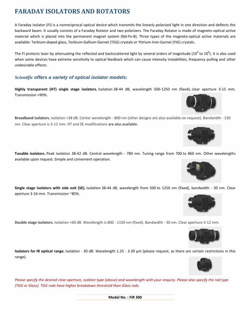
FARADAY ISOLATORS AND ROTATORS
A Faraday Isolator (FI) is a nonreciprocal optical device which transmits the linearly polarized light in one direction and deflects the
backward beam. It usually consists of a Faraday Rotator and two polarizers. The Faraday Rotator is made of magneto-optical active
material which is placed into the permanent magnet system (Nd-Fe-B). Three types of the magneto-optical active materials are
available: Terbium-doped glass, Terbium-Gallium-Garnet (TGG) crystals or Yttrium-Iron-Garnet (YIG) crystals.
The FI protects laser by attenuating the reflected and backscattered light by several orders of magnitude (104 to 10
6). It is also used
when some devices have extreme sensitivity to optical feedback which can cause intensity instabilities, frequency pulling and other
undesirable effects.
Scientific offers a variety of optical isolator models:
Highly transparent (HT) single stage isolators. Isolation 38-44 dB, wavelength 500-1250 nm (fixed), clear aperture 3-15 mm.
Transmission >90%.
Broadband isolators. Isolation >38 dB. Center wavelength - 800 nm (other designs are also available on request). Bandwidth - 130
nm. Clear aperture is 3-12 mm. HT and SE modifications are also available.
Tunable isolators. Peak isolation 38-42 dB. Central wavelength - 780 nm. Tuning range from 700 to 860 nm. Other wavelengths
available upon request. Simple and convenient operation.
Single stage isolators with side exit (SE). Isolation 38-44 dB, wavelength from 500 to 1250 nm (fixed), bandwidth - 30 nm. Clear
aperture 3-16 mm. Transmission ~85%.
Double stage isolators. Isolation >60 dB. Wavelength is 800 - 1150 nm (fixed). Bandwidth - 30 nm. Clear aperture 3-12 mm.
Isolators for IR optical range. Isolation - 30 dB. Wavelength 1.25 - 3.39 µm (please request, as there are certain restrictions in this
range).
Please specify the desired clear aperture, isolator type (above) and wavelength with your enquiry. Please also specify the rod type
(TGG or Glass). TGG rods have higher breakdown threshold than Glass rods.
Model No. : FIR 300
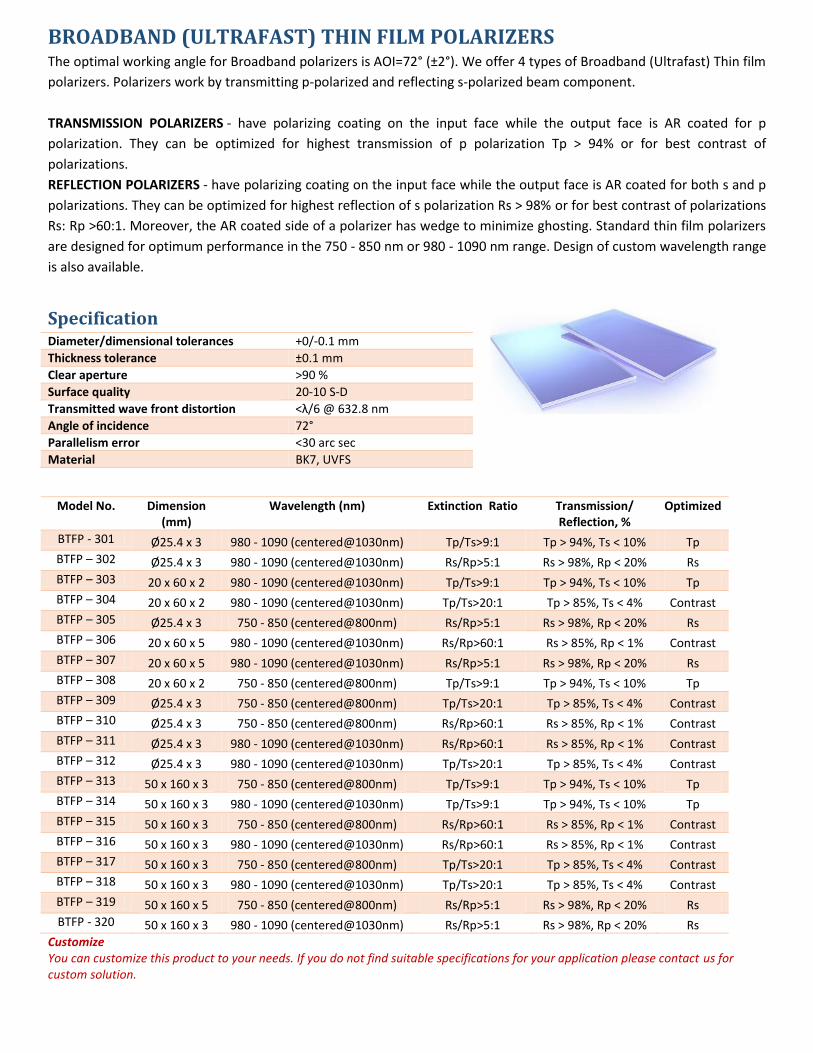
BROADBAND (ULTRAFAST) THIN FILM POLARIZERS The optimal working angle for Broadband polarizers is AOI=72° (±2°). We offer 4 types of Broadband (Ultrafast) Thin film
polarizers. Polarizers work by transmitting p-polarized and reflecting s-polarized beam component.
TRANSMISSION POLARIZERS - have polarizing coating on the input face while the output face is AR coated for p
polarization. They can be optimized for highest transmission of p polarization Tp > 94% or for best contrast of
polarizations.
REFLECTION POLARIZERS - have polarizing coating on the input face while the output face is AR coated for both s and p
polarizations. They can be optimized for highest reflection of s polarization Rs > 98% or for best contrast of polarizations
Rs: Rp >60:1. Moreover, the AR coated side of a polarizer has wedge to minimize ghosting. Standard thin film polarizers
are designed for optimum performance in the 750 - 850 nm or 980 - 1090 nm range. Design of custom wavelength range
is also available.
Specification Diameter/dimensional tolerances +0/-0.1 mm
Thickness tolerance ±0.1 mm
Clear aperture >90 %
Surface quality 20-10 S-D
Transmitted wave front distortion <λ/6 @ 632.8 nm
Angle of incidence 72°
Parallelism error <30 arc sec
Material BK7, UVFS
Model No. Dimension
(mm) Wavelength (nm) Extinction Ratio Transmission/
Reflection, % Optimized
BTFP - 301 Ø25.4 x 3 980 - 1090 (centered@1030nm) Tp/Ts>9:1 Tp > 94%, Ts < 10% Tp
BTFP – 302 Ø25.4 x 3 980 - 1090 (centered@1030nm) Rs/Rp>5:1 Rs > 98%, Rp < 20% Rs
BTFP – 303 20 x 60 x 2 980 - 1090 (centered@1030nm) Tp/Ts>9:1 Tp > 94%, Ts < 10% Tp
BTFP – 304 20 x 60 x 2 980 - 1090 (centered@1030nm) Tp/Ts>20:1 Tp > 85%, Ts < 4% Contrast
BTFP – 305 Ø25.4 x 3 750 - 850 (centered@800nm) Rs/Rp>5:1 Rs > 98%, Rp < 20% Rs
BTFP – 306 20 x 60 x 5 980 - 1090 (centered@1030nm) Rs/Rp>60:1 Rs > 85%, Rp < 1% Contrast
BTFP – 307 20 x 60 x 5 980 - 1090 (centered@1030nm) Rs/Rp>5:1 Rs > 98%, Rp < 20% Rs
BTFP – 308 20 x 60 x 2 750 - 850 (centered@800nm) Tp/Ts>9:1 Tp > 94%, Ts < 10% Tp
BTFP – 309 Ø25.4 x 3 750 - 850 (centered@800nm) Tp/Ts>20:1 Tp > 85%, Ts < 4% Contrast
BTFP – 310 Ø25.4 x 3 750 - 850 (centered@800nm) Rs/Rp>60:1 Rs > 85%, Rp < 1% Contrast
BTFP – 311 Ø25.4 x 3 980 - 1090 (centered@1030nm) Rs/Rp>60:1 Rs > 85%, Rp < 1% Contrast
BTFP – 312 Ø25.4 x 3 980 - 1090 (centered@1030nm) Tp/Ts>20:1 Tp > 85%, Ts < 4% Contrast
BTFP – 313 50 x 160 x 3 750 - 850 (centered@800nm) Tp/Ts>9:1 Tp > 94%, Ts < 10% Tp
BTFP – 314 50 x 160 x 3 980 - 1090 (centered@1030nm) Tp/Ts>9:1 Tp > 94%, Ts < 10% Tp
BTFP – 315 50 x 160 x 3 750 - 850 (centered@800nm) Rs/Rp>60:1 Rs > 85%, Rp < 1% Contrast
BTFP – 316 50 x 160 x 3 980 - 1090 (centered@1030nm) Rs/Rp>60:1 Rs > 85%, Rp < 1% Contrast
BTFP – 317 50 x 160 x 3 750 - 850 (centered@800nm) Tp/Ts>20:1 Tp > 85%, Ts < 4% Contrast
BTFP – 318 50 x 160 x 3 980 - 1090 (centered@1030nm) Tp/Ts>20:1 Tp > 85%, Ts < 4% Contrast
BTFP – 319 50 x 160 x 5 750 - 850 (centered@800nm) Rs/Rp>5:1 Rs > 98%, Rp < 20% Rs
BTFP - 320 50 x 160 x 3 980 - 1090 (centered@1030nm) Rs/Rp>5:1 Rs > 98%, Rp < 20% Rs
Customize You can customize this product to your needs. If you do not find suitable specifications for your application please contact us for custom solution.
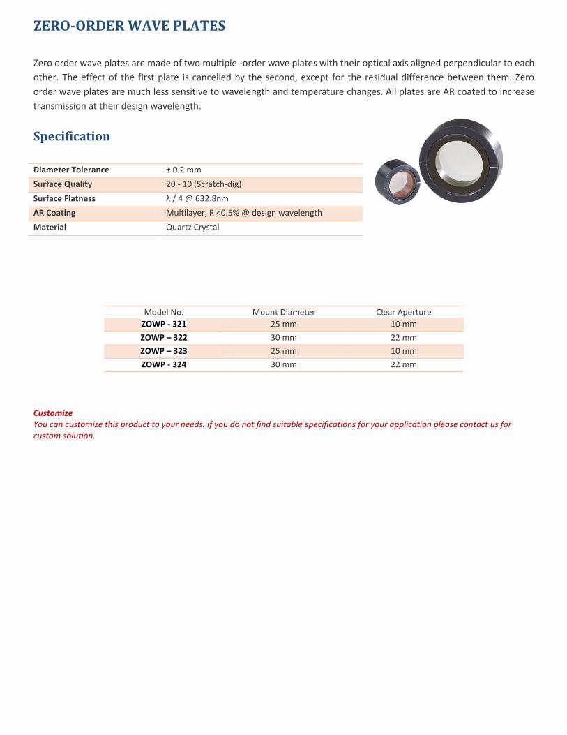
ZERO-ORDER WAVE PLATES
Zero order wave plates are made of two multiple -order wave plates with their optical axis aligned perpendicular to each
other. The effect of the first plate is cancelled by the second, except for the residual difference between them. Zero
order wave plates are much less sensitive to wavelength and temperature changes. All plates are AR coated to increase
transmission at their design wavelength.
Specification
Diameter Tolerance ± 0.2 mm
Surface Quality 20 - 10 (Scratch-dig)
Surface Flatness λ / 4 @ 632.8nm
AR Coating Multilayer, R <0.5% @ design wavelength
Material Quartz Crystal
Model No. Mount Diameter Clear Aperture
ZOWP - 321 25 mm 10 mm
ZOWP – 322 30 mm 22 mm
ZOWP – 323 25 mm 10 mm
ZOWP - 324 30 mm 22 mm
Customize You can customize this product to your needs. If you do not find suitable specifications for your application please contact us for custom solution.
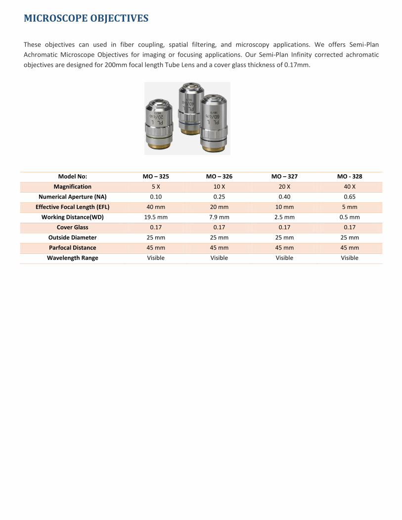
MICROSCOPE OBJECTIVES
These objectives can used in fiber coupling, spatial filtering, and microscopy applications. We offers Semi-Plan
Achromatic Microscope Objectives for imaging or focusing applications. Our Semi-Plan Infinity corrected achromatic
objectives are designed for 200mm focal length Tube Lens and a cover glass thickness of 0.17mm.
Model No: MO – 325 MO – 326 MO – 327 MO - 328
Magnification 5 X 10 X 20 X 40 X
Numerical Aperture (NA) 0.10 0.25 0.40 0.65
Effective Focal Length (EFL) 40 mm 20 mm 10 mm 5 mm
Working Distance(WD) 19.5 mm 7.9 mm 2.5 mm 0.5 mm
Cover Glass 0.17 0.17 0.17 0.17
Outside Diameter 25 mm 25 mm 25 mm 25 mm
Parfocal Distance 45 mm 45 mm 45 mm 45 mm
Wavelength Range Visible Visible Visible Visible