Compact catalogue 2014/2015 - Elpro-Energo · Compact catalogue 2014/2015 Nexans Power Accessories...
76
Compact catalogue 2014/2015 Nexans Power Accessories Germany GmbH
Transcript of Compact catalogue 2014/2015 - Elpro-Energo · Compact catalogue 2014/2015 Nexans Power Accessories...

Compact catalogue 2014/2015Nexans Power Accessories Germany GmbH

Technical instructions and application information
The data given were determined diligently, but do not release our customers of the duty to carry out tests themselves in order to check the suitability of the products delivered by us for the intended use. We reserve the right to modify characteristic and performance data according to the present state of technology. Processing and use of the products cannot be controlled by us and are therefore exclusively in your field of responsibility.
Our products meet the VDE standards respectively correspond to DIN pages and IEC recommendations.
Attention: Before first design in please contact manufacturer.
The products, described in this catalogue, are designed for connection of energy cable conductors (Class 1 & 2) with description of round solid (RE), round stranded (RM), as well as sector solid (SE), sector stranded (SM) and round stranded compacted (RMV).A check on basis of the actual existing conductor dimensions by the user is indispensable. This applies also for the application of flexible conductors (Class 5 & 6).
Impact wrenches have to be approved by Nexans! Depending on different conductor material or conductor type, indicated values may differ from test values acc. to IEC 61238-1. The use of fine stranded conductors has to be approved by Nexans Power Accessories Germany GmbH.
Our responsibilities are only those listed in the latest edition of “General Terms and Conditions for the Supply of Products and Services of the Electrical and Electronics Industry”. If requested we provide a copy.
Our products are mainly delivered in cartons. We only use package materials able to be recycled due to the latest packing system. Collapsible cardboard boxes are not taken back. Please try to order complete standard packages.
Reprinting, even partial, only with special allowance. We reserve the right to alter or modify the characteristics described. Illustrations and drawings may only show a close reflection and are not decisive. The weights are approximate and include the carton package. This catalogue substitutes all former editions. Types or versions not part of the catalogue you receive on request.
Hof, May 2014
1
Table of contentCompany profile - Nexans Power Accessories Germany GmbH Product overview, standard and qualityPremoulded EPDM rubber connectorsApplications for power cable accessories
158LR - Elbow connector152SR - Straight connectorPITO-E - Plug-in terminationConnecting possibilities Interface A
400LR/G - Elbow connectorConnecting possibilities Interface B
Installation overview 430TB/G430TB/G - Compact tee connector300PB/G - Coupling connector300SA - Surge arrester484TB/G - Compact tee connector804PB/G - Coupling connector489TB/G - Compact tee connector809PB/G - Coupling connector800SA - Surge arrester Possible arrangements Interface CConnecting possibilities Interface C
AIN - Indoor slip-on terminationAFN - Outdoor slip-on termination
GTS1 - Heat-shrinkable single core straight jointCSJ - Cold-shrinkable single core straight joint24CSJ-S - Cold-shrinkable compact single core straight jointGTM3.1 - Heat-shrinkable three core transition joint
Ready-to-install, pre-assembled cables
Mechanical cable lugs, C-SeriesCompression cable lugs, copperCompression cable lugs, copper acc. to DIN 46235Compression cable lugs, copper, RMV-typeCompression cable lugs, aluminium acc. to DIN 46329Compression cable lugs, aluminium, RMV-typeMechanical connectors, M-SeriesMechanical connectors, D-SeriesSVMS/SVMS-P Heat-shrinkable in-line joints including mechanical connectors
Cable preparation tools for installationCatalogue selectionCable data sheet / Inquiry form
Up to 42 kV - 1250 A
Side2345
6-78-91011
12-1314
1516-1718-1920-2122-2324-2526-2728-2930-31
3233
34-3637-39
40-4142-4344-4546-47
48-49
50-5152-5354-5556-5758-5960-6162-6364-6566-67
68-717072
1
ACCESSORIES FOR POWER CABLESA compact selection of our accessories
2
15-0
5-20
14
2
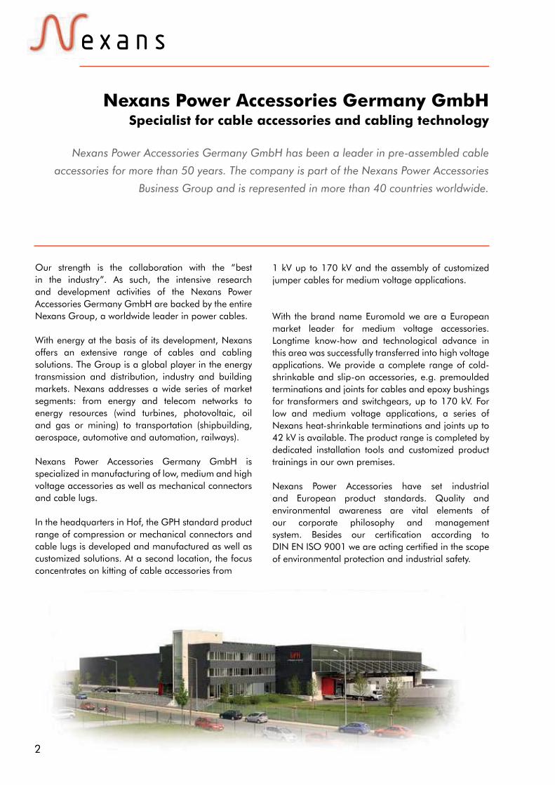
Nexans Power Accessories Germany GmbH has been a leader in pre-assembled cable
accessories for more than 50 years. The company is part of the Nexans Power Accessories
Business Group and is represented in more than 40 countries worldwide.
Our strength is the collaboration with the “best in the industry”. As such, the intensive research and development activities of the Nexans Power Accessories Germany GmbH are backed by the entire Nexans Group, a worldwide leader in power cables.
With energy at the basis of its development, Nexans offers an extensive range of cables and cabling solutions. The Group is a global player in the energy transmission and distribution, industry and building markets. Nexans addresses a wide series of market segments: from energy and telecom networks to energy resources (wind turbines, photovoltaic, oil and gas or mining) to transportation (shipbuilding, aerospace, automotive and automation, railways).
Nexans Power Accessories Germany GmbH is specialized in manufacturing of low, medium and high voltage accessories as well as mechanical connectors and cable lugs.
In the headquarters in Hof, the GPH standard product range of compression or mechanical connectors and cable lugs is developed and manufactured as well as customized solutions. At a second location, the focus concentrates on kitting of cable accessories from
Nexans Power Accessories Germany GmbHSpecialist for cable accessories and cabling technology
1 kV up to 170 kV and the assembly of customized jumper cables for medium voltage applications.
With the brand name Euromold we are a European market leader for medium voltage accessories. Longtime know-how and technological advance in this area was successfully transferred into high voltage applications. We provide a complete range of cold-shrinkable and slip-on accessories, e.g. premoulded terminations and joints for cables and epoxy bushings for transformers and switchgears, up to 170 kV. For low and medium voltage applications, a series of Nexans heat-shrinkable terminations and joints up to 42 kV is available. The product range is completed by dedicated installation tools and customized product trainings in our own premises.
Nexans Power Accessories have set industrial and European product standards. Quality and environmental awareness are vital elements of our corporate philosophy and management system. Besides our certification according to DIN EN ISO 9001 we are acting certified in the scope of environmental protection and industrial safety.

3
Nexans Power Accessories Always the right connection
We are certified.OHRIS, DIN EN ISO 9001:2008,DIN EN ISO 14001:2009
This is where you can find us.Wherever electricity is conductedthrough cables and wires.Wherever cables are connected or energy transmission and dis-tribution is required. Wherever safety and quality have priority.
We demonstrate competence.Nexans products ensure opera-tional reliability as network utili-sation increases. Our referencesinclude more than 50 years ofexperience with over 100 millionconnectors and accessories usedworldwide.
We bear responsibility.The Nexans Power AccessoriesGroup currently produces ac-cessories from 1 kV to 500 kV. As we are the Centre of Compe-tence for cable accessories, we have taken on responsibility for research and development in the Nexans Group for connec-tion technolgy.
What you can expect.Our connectors and accessories have set industry standards and influenced European standards.Quality awareness is a centralcomponent of our companyphilosophy. Our strength lies inpooling the tasks from connec-tion and cabling technology.We show our appreciation for our customers by providing themwith expert and dedicated sup-port.
Advancing into the future with"Smart Grid".Our developments are makinga significant contribution to thecreation of intelligent controlmechanisms for automated en-ergy network structures.
Connectors from 10 kV to 42 kV and 25 mm² to 1200 mm²
158LR 152SR 430TB/G 489TB/G
Terminations from 10 kV to 42 kV and 25 mm² to 1000 mm²
AIN30 AFN30 TTGE3 AIN10 3-core TTGE1TTGI1
Joints from 10 kV to 42 kV and 25 mm² to 1200 mm²
24CSJ
24GTS3
24GTS1
Equipment bushings from 10 kV to 42 kV
400A-24B-0
400AR-3
180AR-3
PITO-E
400CP
Mechanical connectors and compression joints
Norms are important to us.Our accessories meet the re-quirements of the following standards:EN 61442, HD 629.1,HD 629.2, EN 50180,EN 50181, IEC 60137,IEEE 386 & 404, IEC 61238-1, VDE 0220 T100, etc.

4
15-0
5-20
14
EPDM (ethylene propylene diene monomer) in connection technology
Why is EPDM used for slip-on accessories all over the world?
EPDM has been used success-fully as an insulating and con-trol material for many millions of cable connectors worldwide for more than 50 years. Com-pared with the frequency with which other materials, such as silicone, are used for separa-ble connectors, EPDM reaches more than 95%. The separable connectors are used at voltage levels from 3.6/6 kV to26/45 kV (52 kV) in the me-diumvoltage range for all possible applications, such as switching stations, motors, transformers, trains, etc. in both indoor and outdoor facilities. Outer cone solutions have also been used for connecting high-voltage installations up to 220 kV for roughly 10 years.
The following advantages putEPDM in the pole position as the insulating and control ma-terial for separable connectors.
• A thick-walled conductive EPDM jacketwith a high me-chanical load capacity. A metal housing is not necessary.
• The function of the earth connection to the conductive
connector can be removed at any time, if required.
• Due to the dimensionally stable EPDM material, it is not possible to mount the pin con-tact in the wrong place, which often happens with "softer" materials, even with a built-in anti-twist safeguard in the cable lug area. • Due to the hard, smooth sur-face of the EPDM material,damage caused by animalsis not known. In this respect, operational reliability in endan-gered areas is ensured.
• Thanks to innovative further development of the EPDM material and the connector designs, multirange connectors are available today that are characterised by their ease ofinstallation.
From an objective point of view,the EPDM material has clearadvantages in connector tech-nology over all other materi-als, just as silicone for slip-on terminations.
EPDM jacket of the connector is always ensured so that damage to the material caused by elec-tric discharges between the sur-face of the connector / air and the surface of the connector / metal (earthed system parts)is impossible. The EPDM material does not release any volatile substances that collect on the surface having a nega-tive effect on the conductivity of the shielding after a longer period of time.
• Connectors made of EPDM meet all testing requirements of the standards to the utmost satisfaction, including the reig-nition test for detecting a fault, even at low operating voltages, e.g. 6/10 kV. • Problems when removingconnectors (if systems are replaced or moved, even after decades) caused by the mate-rial sticking to the bushing of the system are impossible. The silicone based lubricant that isused when assembling the connector, does not diffuse into the material, but remains in the joint between connector and bushing. The de-energised
5
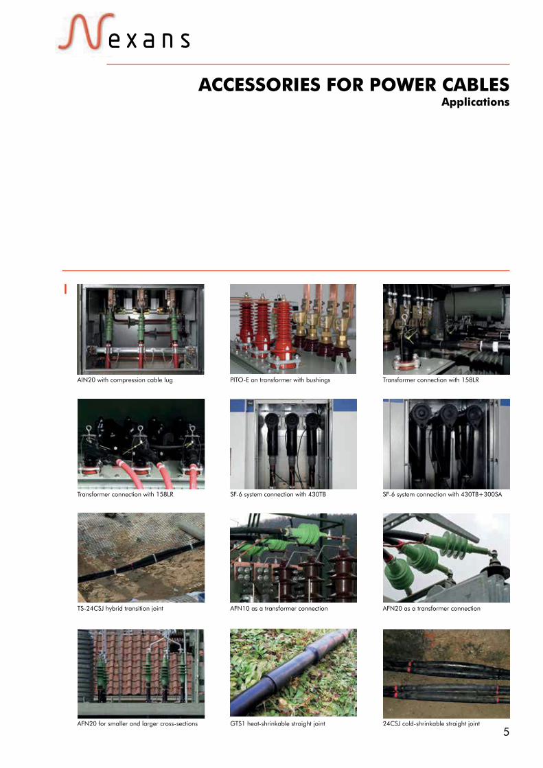
ACCESSORIES FOR POWER CABLESApplications
AIN20 with compression cable lug PITO-E on transformer with bushings Transformer connection with 158LR
Transformer connection with 158LR SF-6 system connection with 430TB SF-6 system connection with 430TB+300SA
TS-24CSJ hybrid transition joint
GTS1 heat-shrinkable straight joint 24CSJ cold-shrinkable straight jointAFN20 for smaller and larger cross-sections
AFN10 as a transformer connection AFN20 as a transformer connection

6
15-0
5-20
14
Up to 24 kV - 250 A
Specifications and standardsThe separable connector (K)158LR and (K)158LR/G meets the requirements of CENELEC HD 629.1.
Design1. Conductive EPDM insert with integrated anti-twist safeguard2. Conductive EPDM jacket.3. Insulating EPDM layer moulded between the insert and the jacket4. Type A - 250 A interface as described by CENELEC EN 50180 and 501815. Bolted or crimp conductor contact6. Cable reducer or cable adaptor7. Earthing lead
158LRInterface A
Elbow connector
6/10 (12) kV6.35/11 (12) kV
8.7/15 (17.5) kV12/20 (24) kV
12.7/22 (24) kV
Separable connector
type
Nominal voltage
U0 /U (kV)
Current
In (A)
Conductor cross-section (mm2)
min. max.
158LR/G
K158LR/G
158LR
158LR
K158LR
K158LR
6/10
12/20
6/10
6/10
12/20
12/20
250
250
250
180
250
180
25
(25) 35
95
150
(25) 35
150
95
95
120
150
120
150
ApplicationSeparable elbow connector designed to connect polymeric insulated cable to equipment (transformers, switchgear, motors...).Also connects cable to cable, using the appropriate mating part.
Technical characteristics • The thick conductive EPDM jacket provides a total safe to touch screen which ensures safety for personnel.• Metal housing is available upon
request.• Integrated anti-twist safeguard• Each separable connector is tested
for AC withstand and partial discharge prior to leaving the factory.
6
1
3
2
4
7
221 mm
160 mm
5
U0 / U (Um )
7Nexans Power Accessories Germany GmbH • Ferdinand-Porsche-Str. 12 • 95028 Hof/Saale • Phone: +49 9281 8306-0E-Mail: [email protected] • www.nexans-power-accessories.com
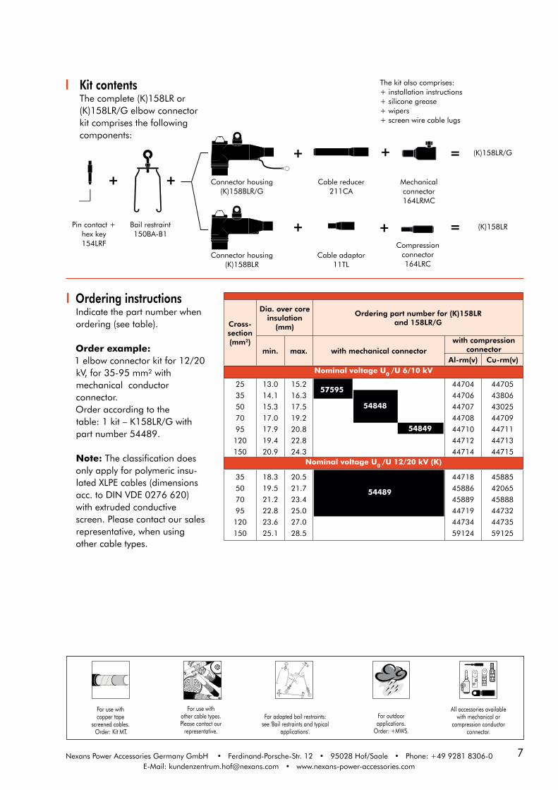
Kit contentsThe complete (K)158LR or (K)158LR/G elbow connector kit comprises the following components:
+
+
+ + Mechanical connector164LRMC
Compression connector 164LRC
Pin contact +hex key154LRF
Bail restraint150BA-B1
Connector housing(K)158BLR
+ (K)158LR=
Cable adaptor11TL
Connector housing(K)158BLR/G
Cable reducer211CA
= (K)158LR/G+
For adapted bail restraints:see 'Bail restraints and typical
applications'.
For outdoorapplications.
Order: +MWS.
All accessories available with mechanical or
compression conductor connector.
For use withcopper tape
screened cables. Order: Kit MT.
For use withother cable types.Please contact our
representative.
The kit also comprises:+ installation instructions+ silicone grease+ wipers+ screen wire cable lugs
Ordering instructionsIndicate the part number whenordering (see table).
Order example:1 elbow connector kit for 12/20kV, for 35-95 mm² with mechanical conductor connector.Order according to thetable: 1 kit – K158LR/G with part number 54489.
Note: The classification does only apply for polymeric insu-lated XLPE cables (dimensions acc. to DIN VDE 0276 620) with extruded conductive screen. Please contact our sales representative, when using other cable types.
Cross-section(mm2)
Dia. over core insulation
(mm)
Ordering part number for (K)158LR and 158LR/G
min. max. with mechanical connectorwith compression
connectorAl-rm(v) Cu-rm(v)
Nominal voltage U0 /U 6/10 kV
25
35
50
70
95
120
150
13.0
14.1
15.3
17.0
17.9
19.4
20.9
15.2
16.3
17.5
19.2
20.8
22.8
24.3
44704
44706
44707
44708
44710
44712
44714
44705
43806
43025
44709
44711
44713
44715Nominal voltage U0 /U 12/20 kV (K)
35
50
70
95
120
150
18.3
19.5
21.2
22.8
23.6
25.1
20.5
21.7
23.4
25.0
27.0
28.5
44718
45886
45889
44719
44734
59124
45885
42065
45888
44732
44735
59125
57595
54848
54849
54489

8
15-0
5-20
14
Up to 24 kV - 250 A
Specifications and standardsThe separable connector (K)152SR and (K)152SR/G meets the requirements of CENELEC HD 629.1.
152SRInterface A
Straight connector
6/10 (12) kV6.35/11 (12) kV
8.7/15 (17.5) kV12/20 (24) kV
12.7/22 (24) kV
ApplicationSeparable straight connector designed to connect polymeric insulated cable to equipment (transformers, switchgear, motors...).Also connects cable to cable, using the appropriate mating part.
Design 1. Conductive EPDM insert2. Conductive EPDM jacket3. Insulating EPDM layer moulded between the insert and the jacket4. Type A - 250 A interface as described by CENELEC EN 50180 and 501815. Bolted or crimp conductor contact6. Cable reducer or cable adaptor7. Earthing lead
Technical characteristics • The thick conductive EPDM
jacket provides a total safe to touch screen which ensures safety for personnel.
• Each separable connector is tested for AC withstand and partial discharge prior to leaving the factory.
Separable connector
type
Nominal voltage
U0 /U (kV)
Current
In (A)
Conductor cross-section (mm2)
min. max.
152SR/G
K152SR/G
152SR
K152SR
6/10
12/20
6/10
12/20
250
250
250
250
25
(25) 35
95
(25) 35
95
95
120
120
255 mm
100 mm
1
2
3
4
6
7
5
U0 / U (Um )

9Nexans Power Accessories Germany GmbH • Ferdinand-Porsche-Str. 12 • 95028 Hof/Saale • Phone: +49 9281 8306-0E-Mail: [email protected] • www.nexans-power-accessories.com
Kit contentsThe complete (K)152SR or (K)152SR/G straight connector kit comprises the following components:
Ordering instructionsIndicate the part number whenordering (see table).
Order example:1 straight connector kit for12/20 kV, for 35-95 mm² mechanical conductor connector.Order according to thetable: 1 kit – K152SR/G with part number 54487.
Note: The classification does only apply for polymeric insu-lated XLPE cables (dimensions acc. to DIN VDE 0276 620) with extruded conductive screen. Please contact our sales representative, when using other cable types.
+
+
+
Bail restraint151BA
Compression connector151SRC
Mechanical connector151SRMC
Connector housing (K)152SRH
+ (K)152SR=
Cable adaptor11TL
Connector housing (K)152SRH/G
Cable reducer211CA
= (K)152SR/G+
The kit also comprises:+ installation instructions+ silicone grease+ wipers + screen wire cable lugs
Cross-section(mm2)
Dia. over core insulation
(mm)
Ordering part number for (K)152SRand 152SR/G
min. max. with mechanical connectorwith compression
connectorAl-rm(v) Cu-rm(v)
Nominal voltage U0 /U 6/10 kV
25
35
50
70
95
120
13.0
14.1
15.3
17.0
17.9
19.4
15.2
16.3
17.5
19.2
20.8
22.8
52138
52140
52141
52143
44745
44747
52139
48775
52142
52144
44746
44748Nominal voltage U0 /U 12/20 kV (K)
35
50
70
95
120
18.3
19.5
21.2
22.8
23.6
20.5
21.7
23.4
25.0
27.0
44792
44794
44795
44797
44799
48227
48228
44796
44798
44800
54487
57283
54850
54851
For adapted bail restraints:see 'Bail restraints and typical
applications'.
For outdoorapplications.
Order: +MWS.
All accessories available with mechanical or
compression conductor connector.
For use withcopper tape
screened cables. Order: Kit MT.
For use withother cable types.Please contact our
representative.

10
15-0
5-20
14
Up to 24 kV - 250 A
Ordering instructionsPlug-in termination PITO-E upto 24 kV.Dedicated fasteningmaterial:+ 2 polyamide bolts,+ 2 polyamide nuts,+ 2 metal pins.
Plug-in termination type
Nominal voltageU0 /U (kV)
CurrentIn (A)
Creepage distance (mm)
Part number
PITO-E 12,7/22 250 510 70275
DesignThe plug-in termination is a moulded epoxy insulated part. It meets the type A - 250 Ainterface as described in CENELEC EN 50180 and 50181.
PITO-EInterface A
Termination
ApplicationSeparable terminationdesigned to connectoverhead lines or busbars to equipment.Is suitable for indoor andoutdoor use for mediumpolluted atmosphere.
6/10 (12) kV6.35/11 (12) kV
8.7/15 (17.5) kV12/20 (24) kV
12.7/22 (24) kV
Technical characteristicsEach plug-in termination is testedfor AC withstand prior to leavingthe factory.
Specifications andstandardsThe PITO-E can be used withequipment interface parts type A that correspond to theinternational standard for outercone systems according toCENELEC EN 50180 and EN 50181.
U0 / U (Um )
90Ø
Ø
Ø
Ø
110Ø
Ø
Nexans Power Accessories Germany GmbH • Ferdinand-Porsche-Str. 12 • 95028 Hof/Saale • Phone: +49 9281 8306-0E-Mail: [email protected] • www.nexans-power-accessories.com

11
CONNECTING POSSIBILITIESPIN-CONNECTOR SYSTEM
Interface A
Interface A250 A outer cone acc. to CENELEC EN 50180 and EN 50181.
6/10 (12) kV6.35/11 (12) kV
8.7/15 (17.5) kV12/20 (24) kV
12.7/22 (24) kV
U0 / U (Um )
Nexans Power Accessories Germany GmbH • Ferdinand-Porsche-Str. 12 • 95028 Hof/Saale • Tel.: +49 9281 8306-0E-Mail: [email protected] • www.nexans-power-accessories.com
Products displayed in grey are generally available, but not included in this catalogue.
PITO-EPlug-in termination
(K)150DR/GDead-end receptacle
Bushings / Accessories /Connectors
Connection Connectors /Accessories
(K)400RTPAReducing tap plug
(K)151SOPStand-off plug
(K)150DPDead-end plug
tap-off630/250 A
in-line junction+ tap off
cableinsulation
tap-off1250/250 A
(K)151SPStraight plug
250GPEarthing plug
180A-24P-OIn-air bushing
(K)180AR-1(-G),-2 & -3(-G)Equipment bushing
Equipment interface
cableearthing
(K)200TTee connector
(K)200XCross connector
(K)200TTee connector
one cable toequipment
(K)200X Cross connector
dead-ending of equipment
two cables to equipment
one line to equipment
three cables to equipment
(K)676RTPAReducing tap plug
(K)152SR(/G)Straight connector
(K)158LR(/G)Elbow connector
(K)400RTPAReducing tap plug
(K)151SOPStand-off plug
(K)150DPDead-end plug
(K)151SPStraight plug
250GPEarthing plug
180A-24P-OIn-air bushing
(K)180AR-1(-G),-2 & -3(-G)Equipment bushing
Equipment interface
(K)200XCross connector
(K)200TTee connector
(K)676RTPAReducing tap plug
(K)150DR/GDead-end receptacle
(K)200TTee connector
(K)200X Cross connector
in-line junction+ 2 tap offs
in-line junction+ 2 tap offs
48
9 min.
Dia. 32.5± 0.2
Dia. 44.5± 0.2
0 - 0.2
Dia. 48.5 ± 0.2
Dia. for Pin 7.9 +0.02
- 0.05
Dia. 31+0.1 - 0.3

12
15-0
5-20
14
Up to 36 kV - 400 A
Specifications andstandardsThe separable connector 400LR/G meets the requirements ofCENELEC HD 629.1.
Design 1. Conductive EPDM insert 2. Conductive EPDM jacket 3. Insulating EPDM layer moulded between the insert and the jacket 4. Type B - 400 A interface as described by CENELEC EN 50180 and 50181 5. Bolted or crimp conductor contact 6. Cable reducer 7. Earthing lead
The screen break designenables cable outer sheathtesting without removing ordismantling the connector.
400LR/GInterface B
Elbow connector
6/10 (12) kV6.35/11 (12) kV
8.7/15 (17.5) kV12/20 (24) kV
12.7/22 (24) kV18/30 (36) kV19/33 (36) kV
210 mm
365 mm
4
1
2
3
7
6
5
Separable connectortype
Nominal voltageU0 /U (kV)
CurrentIn (A)
Conductor cross-section (mm2)
min. max.
400LR/G
K400LR/G
M400LR/G
6/10
12/20
18/30
400
400
400
25
35
50
300
300
240
U0 / U (Um )
ApplicationSeparable elbow connector(plug-in type) designedto connect polymericinsulated cable to equipment(transformers, switchgear,motors...).For use with other cable types please contact our sales representative.
Technical characteristics • The thick conductive EPDM jacket provides a total safe to touch screen which ensures safety for personnel.• Each separable connector is tested for AC withstand and partial discharge prior to leaving the factory.
13Nexans Power Accessories Germany GmbH • Ferdinand-Porsche-Str. 12 • 95028 Hof/Saale • Phone: +49 9281 8306-0E-Mail: [email protected] • www.nexans-power-accessories.com
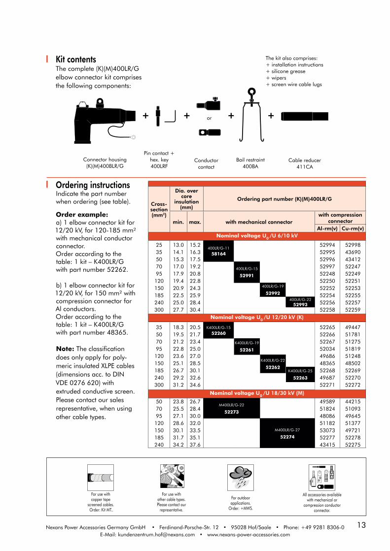
Kit contentsThe complete (K)(M)400LR/Gelbow connector kit comprisesthe following components:
Conductor contact
or
Pin contact +hex. key400LRF
Bail restraint 400BA
Connector housing(K)(M)400BLR/G
Cable reducer 411CA
+ + + +
Cross-section(mm2)
Dia. over core
insulation (mm)
Ordering part number (K)(M)400LR/G
min. max. with mechanical connectorwith compression
connectorAl-rm(v) Cu-rm(v)
Nominal voltage U0 /U 6/10 kV
2535507095120150185240300
13.014.115.317.017.919.420.922.525.027.7
15.216.317.519.220.822.824.325.928.430.4
400LR/G-11
58164
52994529955299652997522485225052252522545225652258
52998436904341252247522495225152253522555225752259
400LR/G-15
52991
400LR/G-19
52992400LR/G-22
52993
Nominal voltage U0 /U 12/20 kV (K)
35507095120150185240300
18.319.521.222.823.625.126.729.231.2
20.521.723.425.027.028.530.132.634.6
K400LR/G-15
52260522655226652267520344968648365522684968752271
494475178151275518195124848502522695227052272
K400LR/G-19
52261
K400LR/G-22
52262K400LR/G-25
52263
Nominal voltage U0 /U 18/30 kV (M)
507095120150185240
23.825.527.128.630.131.734.2
26.728.430.032.033.535.137.6
M400LR/G-22
52273
49589518244808651182530735227743415
44215510934964551377497215227852275
M400LR/G-27
52274
The kit also comprises:+ installation instructions+ silicone grease+ wipers+ screen wire cable lugs
Ordering instructionsIndicate the part number when ordering (see table).
Order example:a) 1 elbow connector kit for12/20 kV, for 120-185 mm²with mechanical conductor connector.Order according to thetable: 1 kit – K400LR/Gwith part number 52262.
b) 1 elbow connector kit for12/20 kV, for 150 mm² withcompression connector forAl conductors.Order according to thetable: 1 kit – K400LR/Gwith part number 48365.
Note: The classification does only apply for poly-meric insulated XLPE cables (dimensions acc. to DINVDE 0276 620) with extruded conductive screen.Please contact our sales representative, when using other cable types.
For use withother cable types.Please contact our
representative.
For use withcopper tape
screened cables. Order: Kit MT..
For outdoorapplications.
Order: +MWS.
All accessories available with mechanical or
compression conductor connector.
14
15-0
5-20
14
Nexans Power Accessories Germany GmbH • Ferdinand-Porsche-Str. 12 • 95028 Hof/Saale • Phone: +49 9281 8306-0E-Mail: [email protected] • www.nexans-power-accessories.com
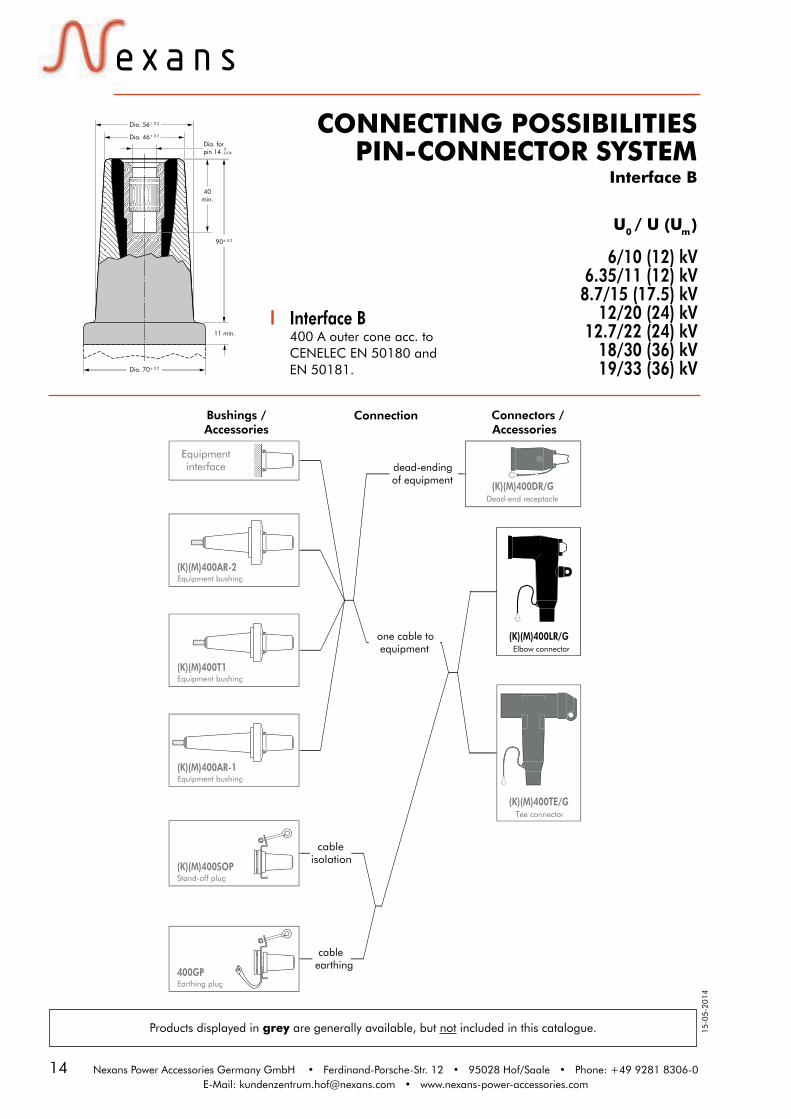
CONNECTING POSSIBILITIESPIN-CONNECTOR SYSTEM
Interface B
Interface B400 A outer cone acc. to CENELEC EN 50180 and EN 50181.
6/10 (12) kV6.35/11 (12) kV
8.7/15 (17.5) kV12/20 (24) kV
12.7/22 (24) kV18/30 (36) kV19/33 (36) kV
U0 / U (Um )
Products displayed in grey are generally available, but not included in this catalogue.
Bushings /Accessories
Connection Connectors /Accessories
(K)(M)400DR/GDead-end receptacle
(K)(M)400LR/GElbow connector
(K)(M)400TE/GTee connector
(K)(M)400AR-2Equipment bushing
(K)(M)400T1Equipment bushing
(K)(M)400AR-1Equipment bushing
(K)(M)400SOPStand-off plug
400GPEarthing plug
Equipmentinterface dead-ending
of equipment
one cable toequipment
cableisolation
cableearthing
(K)(M)400AR-2Equipment bushing
(K)(M)400T1Equipment bushing
(K)(M)400AR-1Equipment bushing
(K)(M)400SOPStand-off plug
400GPEarthing plug
Equipmentinterface
(K)(M)400DR/GDead-end receptacle
(K)(M)400TE/GTee connector
11 min.
Dia. 56± 0.2
Dia. 46± 0.2
40 min.
90± 0.2
Dia. forpin 14 0
- 0.04
Dia. 70± 0.2

15
INSTALLATION OVERVIEWInterface C
Compact tee connector for application in multiple voltage levels430TB/G
groundpotential
earthinglead
cableclamp
conductiverubber
cap
mechanical conductorconnector
cablereducer
cable reducer
lubricate
extrudedconductive screen
tape mark
lubricate
conductor
coreinsulation
cablereducer
connectorhousing
clean up
lubricate
Installation of the connector on the cable
Installation of the connector on the bushing
Earthing and cable fixing
torquewrench
lubricate
equipmentbushing
connectorhousing
lubricate lubricate
socket wrench22 mm
clampingscrew basic
insulatingplug
socket wrench22 mm
torquewrench
extension
Nexans Power Accessories Germany GmbH • Ferdinand-Porsche-Str. 12 • 95028 Hof/Saale • Phone: +49 9281 8306-0E-Mail: [email protected] • www.nexans-power-accessories.com
Mechanical conductor connector
TMBC (95-240)
locking device
AdvantageThe locking device on theTMBC (95-240) mechanical conductor connector prevents the connector housing from sliding back.

16
15-0
5-20
14
ApplicationSuitable for installation on polymeric insulated medium voltage cables with extruded easy strip conductive screen or bonded extruded conductive screen. For use with other cable types please contact our sales representative.
Technical characteristics• The thick conductive EPDM jacket
provides a total safe to touch screen to ensure safety.
• Metal housing available on request.• Thanks to new materials the
430TB/G connectors are non-size sensitive.
• Each separable connector is tested for AC withstand and partial dis-charge prior to leaving the factory.
Up to 36 kV 630 A/1250 A**
Specifications and standardsThe 430TB/G separable connector meets the requirements of CENELEC HD 629.1. ATEX version can be delivered on request.
Separable connector type
Nominal voltageU0 /U (kV)
CurrentIn (A)
Conductor cross-section (mm2)min. max.
430TB/G
K430TB/G
M430TB/G
6/10
12/20
18/30
630/1250**
630/1250**
630/1250**
25
35
50
300
300
240
Design 1. Conductive EPDM insert 2. Conductive EPDM jacket 3. Insulating EPDM layer moulded between the insert and the jacket 4. Type C - interface as described by CENELEC EN 50180 and 50181 5. Bolted or crimp conductor contact 6. Basic insulating plug 7. Cable reducer 8. Conductive rubber cap 9. Clamping screw10. Earth leadThe screen break design enables cable outer sheath testing without removing or dismantling the connector.
430TB/GInterface C
Compact tee connector for multiple voltage levels
6/10 (12) kV6.35/11 (12) kV
8.7/15 (17.5) kV12/20 (24) kV
12.7/22 (24) kV18/30 (36) kV19/33 (36) kV
** When installed on an appropriate equipment bushing.
* The indicated diameter is a die dimension. Depending on the conductor cross-section used, a deviation of up to + 5 mm is possible.
U0 / U (Um )
185 mm
Dia. 80
290 mm
1
3
2
8
7
9
4
10
Dia. 65*
5
6
17Nexans Power Accessories Germany GmbH • Ferdinand-Porsche-Str. 12 • 95028 Hof/Saale • Phone: +49 9281 8306-0E-Mail: [email protected] • www.nexans-power-accessories.com
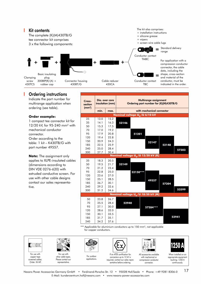
Kit contentsThe complete (K)(M)430TB/Gtee connector kit comprises 3 x the following components:
The kit also comprises:+ installation instructions+ silicone grease+ wipers+ screen wire cable lugs
Clamping screw
430TCS
Basic insulating plug
300BIP(R)/(A) + rubber cap
Connector housing430BT/G
Cable reducer430CA
Conductor contact TMBC
Conductor contact TBC
+ + + +
= Standard delivery range
For application with acompression conductor connector, the cable data, including the shape, cross-section and material of the conductor, must be indicated in the order.
=
Cross-section(mm2)
Dia. over core insulation (mm)
Multirange assignment Ordering part number for (K)(M)430TB/G
min. max. with mechanical connector
Nominal voltage U0 /U 6/10 kV2535507095120150185240300
13.014.115.317.017.919.420.922.525.027.7
15.216.317.519.220.822.824.325.928.430.4
52146
51201
5214752148
57303
Nominal voltage U0 /U 12/20 kV (K)
35507095120150185240300
18.319.521.222.823.625.126.729.231.2
20.521.723.425.027.028.530.132.634.6
52149
52150***
4955757304
53599
Nominal voltage U0 /U 18/30 kV (M)
50 70 95120150185240
23.825.527.128.630.131.734.2
26.728.430.032.033.535.137.6
Ordering instructionsIndicate the part number for multirange application when ordering (see table).
Order example:1 compact tee connector kit for12/20 kV, for 95-240 mm² withmechanical conductor connector.Order according to thetable: 1 kit – K430TB/G with part number 49557.
Note: The assignment only applies to XLPE-insulated cables(dimensions according to DIN VDE 0276-620) with extruded conductive screen. For use with other cable designs contact our sales representa-tive.
57284***
52941
52940
For use withcopper tape
screened cables. Order: Kit MT.
For outdoorapplications.
For use withother cable types.Please contact our
representative.
All accessories available with mechanical or
compression conductor connector.
When installed on an appropriate equipment
bushing: 1250 A continuously.
If an ATEX certification forconnectors up to 12 kV is
required, contact our sales repre-sentative before ordering.
*** Applicable for aluminium conductors up to 150 mm², not applicable for copper conductors.

18
15-0
5-20
14
ApplicationSeparable coupling connector(bolted type) for dual cablearrangement. It has beendesigned to be used with430TB/G separable tee connector.
Technical characteristics• A thick conductive EPDM jacket provides a total safe to touch screen.• Each separable connector is tested for AC withstand and partial discharge prior to leaving the factory.
Up to 36 kV 630 A/1250 A**
300PB/GCoupling connector
for 430TB/G
Specifications andstandardsThe 300PB/G couplingconnector meets therequirements of CENELECHD 629.1. ATEX version can be delivered on request.
Design 1. Interface designed to fit 430TB/G connector 2. Bus for 300PB/G 3. Conductive EPDM insert 4. Insulating EPDM layer moulded between the insert and the jacket 5. Conductive EPDM jacket 6. Conductive EPDM cap 7. Basic insulating plug (with VD point) 8. Bolted or crimp conductor contact 9. Cable reducer10. Earthing leadThe screen break design enablescable outer sheath testing withoutremoving or dismantling theconnector.
** When installed on an appropriate equipment bushing.
6/10 (12) kV6.35/11 (12) kV
8.7/15 (17.5) kV12/20 (24) kV
12.7/22 (24) kV18/30 (36) kV19/33 (36) kV
U0 / U (Um )
Separable connector type
Nominal voltageU0 /U (kV)
CurrentIn (A)
Conductor cross-section (mm2)
min. max.
300PB/G
K300PB/G
M300PB/G
6/10
12/20
18/30
630/1250**
630/1250**
630/1250**
25
35
50
300
300
240
* The indicated diameter is a die dimension. Depending on the conductor cross-section used, a deviation of up to + 5 mm is possible.
290 mm
105 mm 105 mm
395 mm 290 mm
6
430TB/GCompact-tee
connector
1
300PB/GCoupling connector
300PB/GCoupling connector
7
110 mm
105 mm
Dia. 65*
10
2
8
3
4
5
9

19Nexans Power Accessories Germany GmbH • Ferdinand-Porsche-Str. 12 • 95028 Hof/Saale • Phone: +49 9281 8306-0E-Mail: [email protected] • www.nexans-power-accessories.com
Kit contentsThe complete (K)(M)300PBM/Gcoupling connector kit comprises 3 x the following components:
The kit also comprises:+ installation instructions+ silicone grease+ wipers+ screen wire cable lugs
Cross-section(mm2)
Dia. over core insulation (mm)
Multirange assignment Ordering part number for (K)(M)300PB/G
min. max. with mechanical connectorNominal voltage U0 /U 6/10 kV
2535507095120150185240300
13.014.115.317.017.919.420.922.525.027.7
15.216.317.519.220.822.824.325.928.430.4
52999
53000
5300153002
57305
Nominal voltage U0 /U 12/20 kV (K)
35507095120150185240300
18.319.521.222.823.625.126.729.231.2
20.521.723.425.027.028.530.132.634.6
53003
53004***
5300557306
53602
Nominal voltage U0 /U 18/30 kV (M)
50 70 95120150185240
23.825.527.128.630.131.734.2
26.728.430.032.033.535.137.6
57285***
52987
52986
Contact rod Connector housing300BP/G
+
Cable reducer430CA
Conductorcontact TMBC
Conductorcontact TBC
+ +
=
=
Standard delivery range
For application with acompression conductor con-nector, the cable data, includ-ing the shape, cross-section and material of the conductor, must be indicated in the order.
Ordering instructionsIndicate the part number for multirange application when ordering (see table).
Order example:1 coupling connector kit for12/20 kV, for 95-240 mm² withmechanical conductor connector. Order according to thetable: 1 kit – K300PB/G with part number 53005.
Note: The classification does only apply for polymeric insulated XLPE cables (dimen-sions acc. to DIN VDE 0276 620) with extruded conductive screen. Please contact our sales representative, when using other cable types.
For use withcopper tape
screened cables. Order: Kit MT.
For outdoorapplications.
For use withother cable types.Please contact our
representative.
All accessories available with mechanical or
compression conductor connector.
When installed on an appropriate equipment
bushing: 1250 A continuously.
If an ATEX certification forconnectors up to 12 kV is
required, contact our sales repre-sentative before ordering.
*** Applicable for aluminium conductors up to 150 mm², not applicable for copper conductors.

20
15-0
5-20
14
300SASurge arrester for
430TB/G compact tee connector
ApplicationSurge arrester designed toprotect 12, 24 and 36 kVclass components, includingtransformers, equipment, cableand accessories from highvoltage surges resulting fromlightning or switching. It has been designed to be used with the 430TB/G separable teeconnector.
Technical characteristics• This surge arrester is a metal oxide varistor surge arrester that
may only be used in combination with a 430TB/G compact tee or a 300PB/G coupling connector.• Each arrester is tested for AC withstand, partial discharge and critical voltage prior to leaving the factory.
Design 1. Conductive EPDM insert 2. Conductive EPDM jacket 3. Insulating EPDM layer moulded between the insert and the jacket 4. Receptacle for contact rod 5. Earth lead 6. Earth connection 7. Steel cap 8. Metal oxide valve elements 9. Basic insulating plug 10. Interface designed to fit the 430TB/G tee connector.
Surge arrester type
Nominal dis-charge current
In (kA)
Rated voltage*Ur (kV)
Max. continuous operating voltage
Uc (kV)
High current im-pulse withstand
(kA)
Dimensions(mm) Ordering part
numberL1 L2
300SA-5-6N300SA-5-9N300SA-5-12N300SA-5-15N300SA-5-18N300SA-5-22N300SA-5-24N300SA-5-30N300SA-5-33N300SA-5-36N300SA-5-42N300SA-5-45N
555555555555
6912151822243033364245
4.87.29.6
12.014.417.619.224.026.428.833.636.0
656565656565656565656565
250250250250250250350350350350450450
290290290290290290390390390390490490
8574685748857508575285754
On request8575685071
On request857588576085762
Specifications andstandardsThe 300SA surge arresters meetthe test requirements of IEC 60099-4. (VDE 0675-4) ATEX version can be delivered on request.
6/10 (12) kV6.35/11 (12) kV
8.7/15 (17.5) kV12/20 (24) kV
12.7/22 (24) kV18/30 (36) kV19/33 (36) kV
Up to 36 kV
U0 / U (Um )
* Surge arresters for other rated voltages are available on request
Dia. 65
170 mm
105 mm
L2
L1
4
1
10
2
3
8
7
6
5
9
Dia. 80

21Nexans Power Accessories Germany GmbH • Ferdinand-Porsche-Str. 12 • 95028 Hof/Saale • Phone: +49 9281 8306-0E-Mail: [email protected] • www.nexans-power-accessories.com
Typical application and dimensions
Ordering instructionsIndicate the type of surgearrester when ordering (seetable). The part numbers eachapply to one kit consisting ofthree surge arresters.
Order example:For a max. operating voltage of24 kV and a nominal discharge current of 10 kA, order according to the table: Surge arrester type 300SA-10-30N with part number 77658.
Note: The order information onlyapplies to the use in compen-sated, high-impedance and insulated networks.
Surge arrester type
Nominal dis-charge current
In (kA)
Rated voltage*Ur (kV)
Max. continuous operating voltage
Uc (kV)
High current im-pulse withstand
(kA)
Dimensions(mm) Ordering part
numberL1 L2
300SA-10-6N300SA-10-9N300SA-10-12N300SA-10-15N300SA-10-18N300SA-10-22N300SA-10-24N300SA-10-30N300SA-10-33N300SA-10-36N300SA-10-42N300SA-10-45N
101010101010101010101010
6912151822243033364245
4.87.29.6
12.014.417.619.224.026.428.833.636.0
100100100100100100100100100100100100
250250250250250250350350350350450450
290290290290290290390390390390490490
857657781277814776427765577656776577765885728799768576779978
* Surge arresters for other rated voltages are available on request
290 mm
185 mm 105 mm
Tee connectorType (K)(M)430TB/G
Surge arresterType 300SA
110 mm 105 mm
105 mm
395 mm
290 mm
Surge arresterType 300SA
105 mm105 mm110 mm
Tee connectorType (K)(M)430TB/G
Coupling connectorType (K)(M)300PB/G

22
15-0
5-20
14
Up to 42 kV630 A/1250 A**
484TB/GInterface C
Compact tee connector for multiple voltage levels
Technical characteristics• The thick conductive EPDM jacket provides a total safe to touch screen to ensure safety.• Thanks to new materials the 484TB/G connectors are non-size sensitive.• Each separable connector is tested for AC withstand and partial discharge prior to leaving the factory.
ApplicationSuitable for installation onpolymeric insulated mediumvoltage cables with extrudedeasy strip conductive screen orbonded extruded conductivescreen. For use with other cabletypes please contact our salesrepresentative.
Design 1. Conductive EPDM insert 2. Conductive EPDM jacket 3. Insulating EPDM layer moulded between the insert and the jacket 4. Type C - interface as described by CENELEC EN 50180 and 50181 5. Bolted or crimp conductor contact 6. Basic insulating plug 7. Cable reducer 8. Conductive rubber cap 9. Clamping screw 10. Earth leadThe screen break designenables cable outer sheathtesting without removing ordismantling the connector.
Specifications andstandardsThe 484TB/G separableconnector meets therequirements of CENELEC HD629.1. ATEX version can bedelivered on request.
Separable connectortype
Nominal voltageU0 /U (kV)
CurrentIn (A)
Conductor cross-section (mm2)
min. max.
484TB/GK484TB/GM484TB/GP484TB/G
6/1012/2018/30
20.8/36
630/1250**630/1250**630/1250**630/1250**
70355050
630630630630
6/10 (12) kV6.35/11 (12) kV
8.7/15 (17.5) kV12/20 (24) kV
12.7/22 (24) kV18/30 (36) kV19/33 (36) kV
20.8/36 (42) kV
** When installed on an appropriate equipment bushing
U0 / U (Um )
* The indicated diameter is a die dimension. Depending on the conductorcross-section used, a deviation of up to + 5 mm is possible.
185 mm
4 9
1
2
3
10
7
360 mm
5
6
8
Dia. 80
Dia. 80*

23Nexans Power Accessories Germany GmbH • Ferdinand-Porsche-Str. 12 • 95028 Hof/Saale • Phone: +49 9281 8306-0E-Mail: [email protected] • www.nexans-power-accessories.com
Ordering instructionsIndicate the part number for multirange application when ordering (see table).
Order example:1 compact tee connector kitfor 12/20 kV, for 120-240 mm²with mechanical conductor con-nector.Order according to thetable: K484TB/G with part number 57386.
Note: The classification does only apply for polymeric insulated XLPE cables (dimensions acc. to DIN VDE 0276 620) with extruded conductive screen.
*** Since the dimensions forcables at voltage level 20.8/36(42) kV are not yet standardised,the conductor cross-sections and their assignment of diameters over core insulation given in the table are to be considered approximate values. When ordering accessories, we would like to ask you to indicate the checked diameters over core insulation.
Kit contentsThe complete (K)(M)(P)484TB/Gtee connector kit comprises 3x the following components:
The kit also comprises:+ installation instructions+ silicone grease+ wipers+ screen wire cable lugs
Connector housing(K)(M)(P)484BT/G
Cable reducer 611CA
Conductor contact TMBC
Conductor contact
TBC
Basic insulating plug
(K)(M)(P)800BIPA + rubber cap
Standard delivery range
For application with acompression conductor connector, the cable data, including the shape, cross-section and material of the conductor, must be indicated in the order.
M16stud with
spring washer and nut
Cross-section(mm2)
Dia. over core insulation (mm)
Multirange assignment Ordering part number for (K)(M)(P)484TB/G
min. max. with mechanical connectorNominal voltage U0 /U 6/10 kV
70 17.0 19.25737995 17.9 20.8
120 19.4 22.8150 20.9 24.3
57380185 22.5 25.9240 25.0 28.4 57381300 27.7 30.4400 30.9 33.6 57382500 33.7 36.4 57383630 37.1 40.8
Nominal voltage U0 /U 12/20 kV (K)35 18.3 20.5
5738450 19.5 21.770 21.2 23.4
5738595 22.8 25.0120 23.6 27.0
57386150 25.1 28.5185 26.7 30.1240 29.2 32.6
57387300 31.2 34.6400 34.4 37.8500 37.2 40.6 57388630 41.3 45.0 57461
Nominal voltage U0 /U 18/30 kV (M)50 23.8 26.7
5738970 25.5 28.495 27.1 30.0120 28.6 32.0
57390150 30.1 33.5185 31.7 35.1240 34.2 37.6
57391300 36.2 39.6400 39.4 42.8500 42.2 45.6 57392630 46.3 50.0
Nominal voltage U0 /U 20.8/36 kV*** (P)50 23.8 26.7
5739370 25.5 28.495 27.1 30.0120 28.6 32.0
57394150 30.1 33.5185 31.7 35.1240 34.2 37.6
57395300 36.2 39.6400 39.4 42.8500 42.2 54.6
57396630 46.3 50.0
For use withcopper tape
screened cables. Order: Kit MT.
For outdoorapplications.
For use withother cable types.Please contact our
representative.
All accessories available with mechanical or
compression conductor connector.
When installed on an appropriate equipment
bushing: 1250 A continuously.

24
15-0
5-20
14
Technical characteristics• A thick conductive EPDM jacket provides a total safe to touch screen.• Each separable connector is tested for AC withstand and partial discharge prior to leaving the factory.
Up to 42 kV630 A / 1250 A**
804PB/GCoupling connector
for 484TB/G
Specifications andstandardsThe 804PB/G coupling connec-tor meets the requirements ofCENELEC HD 629.1. ATEX version can be delivered on request.
Separable connectortype
Nominal voltageU0 /U (kV)
CurrentIn (A)
Conductor cross-section (mm2)
min. max.
804PB/GK804PB/GM804PB/GP804PB/G
6/1012/2018/30
20.8/36
630/1250**630/1250**630/1250**630/1250**
70355050
630630630630
6/10 (12) kV6.35/11 (12) kV
8.7/15 (17.5) kV12/20 (24) kV
12.7/22 (24) kV18/30 (36) kV19/33 (36) kV
20.8/36 (42) kV
ApplicationSeparable coupling connector(bolted type) for dual cablearrangement. It has beendesigned to be used with484TB/G separable teeconnector.The cable arrangement mightbe extended by multiplecoupling connectors.
U0 / U (Um )
** When installed on an appropriate equipment bushing
Design 1. Interface designed to fit 484TB/G tee connector 2. Bus for 804PB/G 3. Bolted or crimp conductor contact 4. Conductive EPDM insert 5. Conductive EPDM jacket 6. Insulating EPDM layer moulded between the insert and the jacket 7. Cable reducer 8. Conductive EPDM cap 9. Basic insulating plug (with VD point) 10. Earth leadThe screen break designenables cable outer sheath testing without removing or dismantling the connector.
* The indicated diameter is a die dimension. Depending on the conductorcross-section used, a deviation of up to + 5 mm is possible.
360 mm
110 mm 110 mm
Tee connector Type 484TB/G
Coupling connectorType 804PB/G
Coupling connectorType 804PB/G
110 mm
1
400 mm 290 mm 110 mm
4
3
6
2
5
7
8
9
10
Dia. 80*

25Nexans Power Accessories Germany GmbH • Ferdinand-Porsche-Str. 12 • 95028 Hof/Saale • Phone: +49 9281 8306-0E-Mail: [email protected] • www.nexans-power-accessories.com
Kit contentsThe complete (K)(M)(P)804PB/G coupling connector kit comprises 3 x the followingcomponents:
Connector housing (K)(M)(P)804BP/G
Conductor contact TBC
Conductor contact TMBC
Contact rod and stud
Cable reducer 611CA
Ordering instructionsIndicate the part number for multirange application when ordering (see table).
Order example:1 coupling connector for 12/20kV, for 120-240 mm² with me-chanical conductor connector.Order according to thetable: K804PB/G with part number 57404.
Note: The classification does only apply for polymeric insulated XLPE cables (dimensions acc. to DIN VDE 0276 620) with extruded conductive screen.
*** Since the dimensions forcables at voltage level 20.8/36(42) kV are not yet standardised,the conductor cross-sections and their assignment of diametersover core insulation given inthe table are to be consideredapproximate values. When ordering accessories, we would like to ask you to indicate the checked diameters over core insulation.
The kit also comprises:+ installation instructions+ silicone grease+ wipers+ screen wire cable lugs
Standard delivery range
For application with acompression conductor connector, the cable data, including the shape, cross-section and material of the conductor, must be indicated in the order.
Cross-section(mm2)
Dia. over core insulation (mm)
Multirange assignment Ordering part number for (K)(M)(P)804PB/G
min. max. with mechanical connectorNominal voltage U0 /U 6/10 kV
70 17.0 19.25739795 17.9 20.8
120 19.4 22.8150 20.9 24.3
57398185 22.5 25.9240 25.0 28.4 57399300 27.7 30.4400 30.9 33.6 57400500 33.7 36.4 57401630 37.1 40.8
Nominal voltage U0 /U 12/20 kV (K)35 18.3 20.5
5740250 19.5 21.770 21.2 23.4
5740395 22.8 25.0120 23.6 27.0
57404150 25.1 28.5185 26.7 30.1240 29.2 32.6
57405300 31.2 34.6400 34.4 37.8500 37.2 40.6 57406630 41.3 45.0 57462
Nominal voltage U0 /U 18/30 kV (M)50 23.8 26.7
5740770 25.5 28.495 27.1 30.0120 28.6 32.0
57408150 30.1 33.5185 31.7 35.1240 34.2 37.6
57409300 36.2 39.6400 39.4 42.8500 42.2 45.6 57410630 46.3 50.0
Nominal voltage U0 /U 20.8/36 kV*** (P)50 23.8 26.7
5741170 25.5 28.495 27.1 30.0120 28.6 32.0
57412150 30.1 33.5185 31.7 35.1240 34.2 37.6
57413300 36.2 39.6400 39.4 42.8500 42.2 54.6 57414630 46.3 50.0
For use withcopper tape
screened cables. Order: Kit MT.
For outdoorapplications.
For use withother cable types.Please contact our
representative.
All accessories available with mechanical or
compression conductor connector.
When installed on an appropriate equipment
bushing: 1250 A continuously.

26
15-0
5-20
14
Up to 42 kV630 A/1250 A**
489TB/GInterface C
Compact tee connector for multiple voltage levels
Design 1. Conductive EPDM insert 2. Conductive EPDM jacket 3. Insulating EPDM layer moulded between the insert and the jacket 4. Type C - interface as described by CENELEC EN 50180 and 50181 5. Bolted or crimp conductor contact 6. Basic insulating plug (with VD point) 7. Cable reducer 8. Conductive rubber cap 9. M16 Clamping screw with spring washer and nut 10. Earth leadThe screen break designenables cable outer sheathtesting without removing ordismantling the connector.
Specifications and standardsThe 489TB/G separable connec-tor meets the requirements of CENELEC HD 629.1.
Separable connectortype
Nominal voltageU0 /U (kV)
CurrentIn (A)
Conductor cross-section (mm2)***
min. max.
489TB/GK489TB/GM489TB/GP489TB/G
6/1012/2018/30
20.8/36
630/1250**630/1250**630/1250**630/1250**
800800800800
1200120012001200
6/10 (12) kV6.35/11 (12) kV
8.7/15 (17.5) kV12/20 (24) kV
12.7/22 (24) kV18/30 (36) kV19/33 (36) kV
20.8/36 (42) kV
U0 / U (Um )
Technical characteristics• The thick conductive EPDM jacket
provides a total safe to touch screen to ensure safety.
• Thanks to new materials the 489TB/G connectors are non-size sensitive.• Each separable connector is tested
for AC withstand and partial discharge prior to leaving the factory.
ApplicationThe interface C T-Connector type 489TB/G is suitable for installation on polymeric insulated medium voltage cables with extruded easy strip conductive screen or bonded extruded conductive screen. For usage with other cable types please contact our sales representative.
*** Other cross sections on request.** When installed on an appropriate equipment bushing.
* The indicated diameter is a die dimension. Depending on the conductorcross-section used, a deviation of up to + 5 mm is possible.
185 mm
4 9
1
2
3
7
460 mm
5
6
8
10
Dia. 80
Dia. 110*
27Nexans Power Accessories Germany GmbH • Ferdinand-Porsche-Str. 12 • 95028 Hof/Saale • Phone: +49 9281 8306-0E-Mail: [email protected] • www.nexans-power-accessories.com
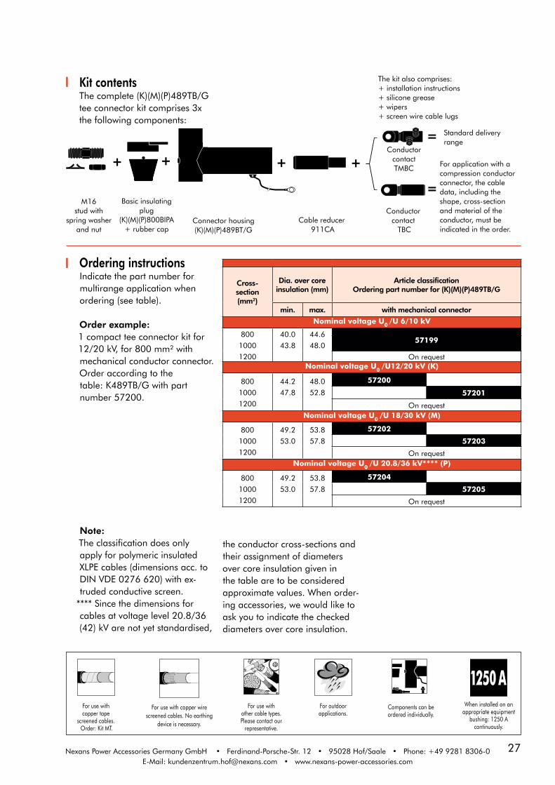
Ordering instructionsIndicate the part number for multirange application when ordering (see table).
Order example:1 compact tee connector kit for12/20 kV, for 800 mm² withmechanical conductor connector.Order according to thetable: K489TB/G with part number 57200.
Note: The classification does onlyapply for polymeric insulated XLPE cables (dimensions acc. to DIN VDE 0276 620) with ex-truded conductive screen.
**** Since the dimensions forcables at voltage level 20.8/36(42) kV are not yet standardised,
Kit contentsThe complete (K)(M)(P)489TB/Gtee connector kit comprises 3xthe following components:
The kit also comprises:+ installation instructions+ silicone grease+ wipers+ screen wire cable lugs
Connector housing(K)(M)(P)489BT/G
Cable reducer 911CA
Conductor contact TMBC
Conductor contact TBC
Basic insulating plug
(K)(M)(P)800BIPA + rubber cap
Standard delivery range
For application with acompression conductor connector, the cable data, including the shape, cross-section and material of the conductor, must be indicated in the order.
Cross- section(mm2)
Dia. over core insulation (mm)
Article classification Ordering part number for (K)(M)(P)489TB/G
min. max. with mechanical connector
Nominal voltage U0 /U 6/10 kV
800
1000
1200
40.0
43.8
44.6
48.057199
On requestNominal voltage U0 /U12/20 kV (K)
800
1000
1200
44.2
47.8
48.0
52.8
57200
57201
On requestNominal voltage U0 /U 18/30 kV (M)
800
1000
1200
49.2
53.0
53.8
57.8
57202
57203
On requestNominal voltage U0 /U 20.8/36 kV**** (P)
800
1000
1200
49.2
53.0
53.8
57.8
57204
57205
On request
the conductor cross-sections andtheir assignment of diametersover core insulation given inthe table are to be consideredapproximate values. When order-ing accessories, we would like to ask you to indicate the checked diameters over core insulation.
M16stud with
spring washer and nut
For use withcopper tape
screened cables. Order: Kit MT.
For outdoorapplications.
For use withother cable types.Please contact our
representative.
Components can be ordered individually.
When installed on an appropriate equipment
bushing: 1250 A continuously.
For use with copper wire screened cables. No earthing
device is necessary.

28
15-0
5-20
14
809PB/GCoupling connector
for 489TB/G
Specifications and standardsThe 809PB/G coupling connec-tor meets the requirements of CENELEC HD 629.1.
Design 1. Interface designed to fit 489TB/G tee connector 2. Bus for 809PB/G 3. Bolted or crimp conductor contact 4. Conductive EPDM insert 5. Conductive EPDM jacket 6. Insulating EPDM layer moulded between the insert and the jacket 7. Cable reducer 8. Conductive rubber cap 9. Basic insulating plug (with VD point) 10. Earth lead
The screen break design enablescable outer sheath testing withoutremoving or dismantling theconnector.
Separable connectortype
Nominal voltageU0 /U (kV)
CurrentIn (A)
Conductor cross-section (mm2)***
min. max.
809PB/GK809PB/GM809PB/GP809PB/G
6/1012/2018/30
20.8/36
630/1250**630/1250**630/1250**630/1250**
800800800800
1200120012001200
Up to 42 kV630 A/1250 A**
6/10 (12) kV12/20 (24) kV18/30 (36) kV
20.8/36 (42) kV
U0 / U (Um )
Technical characteristics• A thick conductive EPDM jacket provides a total safe to touch screen.• Each separable connector is tested for AC withstand and partial discharge prior to leaving the factory.
ApplicationSeparable coupling connector(bolted type) for dual cablearrangement. It has beendesigned to be used with489TB/G separable teeconnector.The cable arrangement mightbe extended by multiplecoupling connectors.
* The indicated diameter is a die dimension. Depending on the conductorcross-section used, a deviation of up to + 5 mm is possible.
110 mm 120 mm 120 mm
460 mm
420 mm 300 mm 120 mm
Tee connectorType 489TB/G
Coupling connector
Type 809PB/G
Coupling connector
Type 809PB/G
1
8
9
2
5
3
4
6
7
10
Dia. 110*
*** Other cross sections on request.** When installed on an appropriate equipment bushing.

29Nexans Power Accessories Germany GmbH • Ferdinand-Porsche-Str. 12 • 95028 Hof/Saale • Phone: +49 9281 8306-0E-Mail: [email protected] • www.nexans-power-accessories.com
Ordering instructionsIndicate the part number for multirange application when ordering (see table).
Order example:1 coupling connector kit for12/20 kV, for 800 mm² withmechanical conductor connector. Order according to thetable: K809PB/G with partnumber 57207.
Note: The classification does onlyapply for polymeric insulated XLPE cables (dimensions acc. to DIN VDE 0276 620) with extruded conductive screen.
**** Since the dimensions forcables at voltage level 20.8/36 (42) kV are not yet standardised, the conductor
Kit contentsThe complete (K)(M)(P)809PB/Gcoupling connector kit comprises 3 x the following components:
Connector housing (K)(M)(P)809BP/G
Conductor contact
TBC
Conductor contact TMBC
Contact rod and stud
Cable reducer911CA
The kit also comprises:+ installation instructions+ silicone grease+ wipers+ screen wire cable lugs
Standard delivery range
For application with acompression conductor connector, the cable data, including the shape, cross-section and material of the conductor, must be indicated in the order.
Cross- section(mm2)
Dia. over core insulation (mm)
Article classification Ordering part number for (K)(M)(P)809PB/G
min. max. with mechanical connector
Nominal voltage U0 /U 6/10 kV
800
1000
1200
40.0
43.8
44.6
48.057206
On requestNominal voltage U0 /U 12/20 kV (K)
800
1000
1200
44.2
47.8
48.0
52.8
57207
57208
On requestNominal voltage U0 /U 18/30 kV (M)
800
1000
1200
49.2
53.0
53.8
57.8
57209
57210
On requestNominal voltage U0 /U 20.8/36 kV**** (P)
800
1000
1200
49.2
53.0
53.8
57.8
57211
57212
On request
cross-sections and their assignment of diameters over core insulation given in the table are to be considered approximate values. When ordering accessories, we would like to ask you to indicate the checked diameters over core insulation.
For use withcopper tape
screened cables. Order: Kit MT.
For outdoorapplications.
For use withother cable types.Please contact our
representative.
Components can be ordered individually.
When installed on an appropriate equipment
bushing: 1250 A continuously.
For use with copper wire screened cables. No earthing
device is necessary.
30
15-0
5-20
14
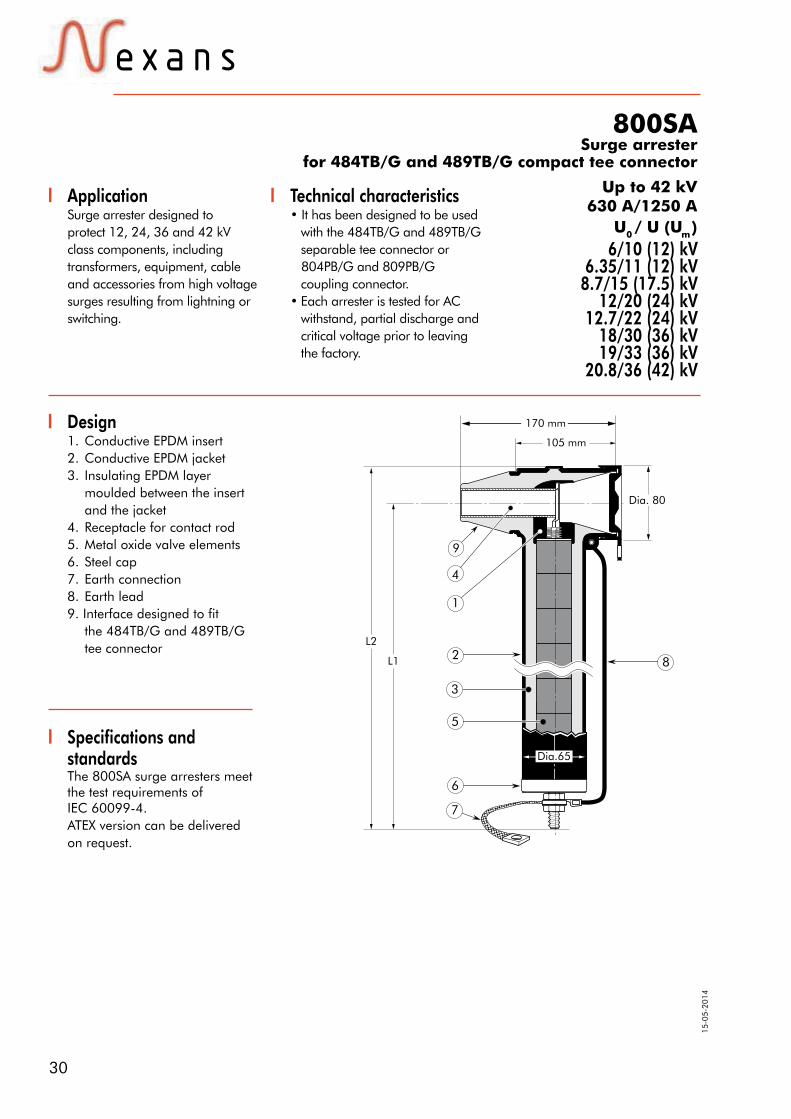
800SASurge arrester
for 484TB/G and 489TB/G compact tee connector
ApplicationSurge arrester designed toprotect 12, 24, 36 and 42 kVclass components, includingtransformers, equipment, cableand accessories from high voltagesurges resulting from lightning orswitching.
Design1. Conductive EPDM insert2. Conductive EPDM jacket3. Insulating EPDM layer moulded between the insert and the jacket4. Receptacle for contact rod5. Metal oxide valve elements6. Steel cap7. Earth connection8. Earth lead9. Interface designed to fit the 484TB/G and 489TB/G tee connector
Specifications andstandardsThe 800SA surge arresters meetthe test requirements of IEC 60099-4. ATEX version can be delivered on request.
Technical characteristics• It has been designed to be used
with the 484TB/G and 489TB/G separable tee connector or
804PB/G and 809PB/G coupling connector.
• Each arrester is tested for AC withstand, partial discharge and critical voltage prior to leaving the factory.
6/10 (12) kV6.35/11 (12) kV
8.7/15 (17.5) kV12/20 (24) kV
12.7/22 (24) kV18/30 (36) kV19/33 (36) kV
20.8/36 (42) kV
Up to 42 kV630 A/1250 A
U0 / U (Um )
6
7
105 mm
170 mm
L2
L1 8
5
3
2
1
4
9
Dia.65
Dia. 80
31Nexans Power Accessories Germany GmbH • Ferdinand-Porsche-Str. 12 • 95028 Hof/Saale • Phone: +49 9281 8306-0E-Mail: [email protected] • www.nexans-power-accessories.com
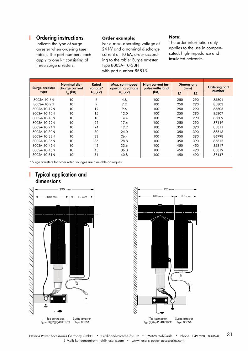
Surge arrester type
Nominal dis-charge current
In (kA)
Rated voltage*Ur (kV)
Max. continuous operating voltage
Uc (kV)
High current im-pulse withstand
(kA)
Dimensions(mm) Ordering part
numberL1 L2
800SA-10-6N800SA-10-9N800SA-10-12N800SA-10-15N800SA-10-18N800SA-10-22N800SA-10-24N800SA-10-30N800SA-10-33N800SA-10-36N800SA-10-42N800SA-10-45N800SA-10-51N
10101010101010101010101010
691215182224303336424551
4.87.29.6
12.014.417.619.224.026.428.833.636.040.8
100100100100100100100100100100100100100
250250250250250250350350350350450450450
290290290290290290390390390390450490490
85801858038580585807858098714985811858138699885815858178581987147
* Surge arresters for other rated voltages are available on request
Typical application and dimensions
Ordering instructionsIndicate the type of surgearrester when ordering (seetable). The part numbers eachapply to one kit consisting ofthree surge arresters.
Order example:For a max. operating voltage of24 kV and a nominal discharge current of 10 kA, order accord-ing to the table: Surge arrester type 800SA-10-30Nwith part number 85813.
Note: The order information onlyapplies to the use in compen-sated, high-impedance and insulated networks.
290 mm
180 mm 110 mm
290 mm
110 mm180 mm
Tee connectorType (K)(M)(P)484TB/G
Tee connectorTyp (K)(M)(P) 489TB/G
Surge arresterType 800SA
Surge arresterType 800SA
32
15-0
5-20
14
Nexans Power Accessories Germany GmbH • Ferdinand-Porsche Str. 12 • 95028 Hof/Saale • Phone: +49 9281 8306-0E-Mail: [email protected] • www.nexans-power-accessories.com
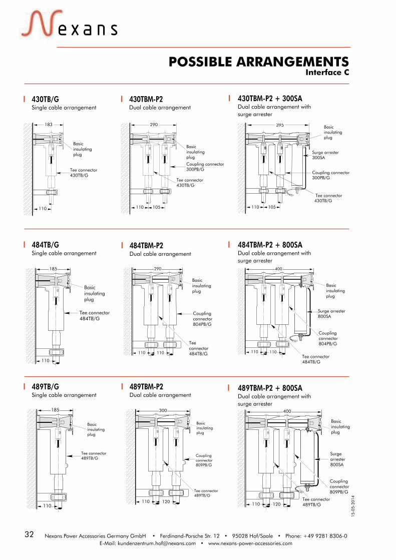
POSSIBLE ARRANGEMENTSInterface C
430TB/GSingle cable arrangement
183
110
Tee connector430TB/G
Basic insulatingplug
484TB/GSingle cable arrangement
110
Tee connector484TB/G
Basic insulating plug
185
430TBM-P2Dual cable arrangement
290
110 105
Tee connector430TB/G
Coupling connector300PB/G
Basic insulating plug
484TBM-P2Dual cable arrangement
Tee connector484TB/G
Couplingconnector804PB/G
Basic insulating plug
110 110
290
430TBM-P2 + 300SA Dual cable arrangement withsurge arrester
110 105
395 Basic insulating plug
Coupling connector300PB/G
Tee connector430TB/G
Surge arrester300SA
484TBM-P2 + 800SA Dual cable arrangement withsurge arrester
110
Couplingconnector804PB/G
Tee connector484TB/G
Basicinsulatingplug
Surge arrester800SA
110
400
110
Tee connector489TB/G
Basic insulatingplug
185
Tee connector489TB/G
Couplingconnector809PB/G
Basic insulatingplug
110 120
300
Tee connector489TB/G110 120
400
Basic insulatingplug
Surge arrester 800SA
Couplingconnector809PB/G
489TB/GSingle cable arrangement
489TBM-P2Dual cable arrangement
489TBM-P2 + 800SA Dual cable arrangement withsurge arrester

33
CONNECTING POSSIBILITIESBOLTED CONNECTOR SYSTEM
Interface C
Interface C1+C2630 A / 1250 A outer cone acc. to CENELEC EN 50180 and EN 50181.
U0 / U (Um ) 6/10 (12) kV
6.35/11 (12) kV8.7/15 (17.5) kV
12/20 (24) kV12.7/22 (24) kV
18/30 (36) kV19/33 (36) kV
20.8/36 (42) kV
Nexans Power Accessories Germany GmbH • Ferdinand-Porsche-Str. 12 • 95028 Hof/Saale • Phone: +49 9281 8306-0E-Mail: [email protected] • www.nexans-power-accessories.com
Products displayed in grey are generally available, but not included in this catalogue.
M16 x 2 - 6H
11 min.
Dia. 56± 0.2
Dia. 46± 0.2
Dia. 22min.
1.5 0 - 0.5
29 min.
90± 0.2
Dia. 70± 0.2
(K)(M)300PB/GCoupling connector
300SASurge arrester
dead-endingof equipment (K)(M)400DR-B
Dead-end receptacle
cableearthing
tap-off630/250A
in-linejunction
(K)400LB/GElbow connector
(K)(M)(P)400TB/G
(K)(M)(P)440TB/G
(K)(M)430TB/GTee connector
Equipmentinterface
(K)(M)400AR-3Equipment bushing
400A-24BIn-air bushing
(K)(M)400SOP-BStand-off plug
400GP-BEarthing plug
(K)400RTPAReducing tap plug
(K)(M)440CPConnecting plug
(K)(M)400CP-SCConnecting plug
(K)(M)400SFR-BEquipment bushing
(K)(M)400AR-6Equipment bushing
(K)(M)400AR-4Equipment bushing
(K)(M)400AR-5Equipment bushing
cable to equipment
cableisolation
400PB-XSASurge arrester
Surge arrester
(K)(M)440PB/GCoupling connector
(K)(M)434TB/G
(K)(M)(P)484TB/G (K)(M)(P)804PB/G
(K)(M)(P)809PB/G
Tee connector
Tee connector
Tee connector
Tee connector
Tee connector(K)(M)(P)489TB/G
Equipmentinterface
(K)(M)400AR-3Equipment bushing
400A-24BIn-air bushing
(K)(M)400SOP-BStand-off plug
400GP-BEarthing plug
(K)400RTPAReducing tap plug
(K)(M)440CPConnecting plug
(K)(M)400CP-SCConnecting plug
(K)(M)400SFR-BEquipment bushing
(K)(M)400AR-6Equipment bushing
(K)(M)400AR-4Equipment bushing
(K)(M)400AR-5Equipment bushing
(K)(M)400DR-BDead-end receptacle
(K)400LB/GElbow connector
(K)(M)(P)400TB/G
(K)(M)(P)440TB/G
(K)(M)434TB/GTee connector
Tee connector
Tee connector400PB-XSASurge arrester
(K)(M)440PB/GCoupling connector
800SA
in-linejunction
Coupling connector
Coupling connector

34
15-0
5-20
14
AINIndoor slip-on termination
Up to 42 kV
Termination type
Nominal voltage
U0 /U (kV)
Conductor cross-section (mm2) *
min. max.
AIN 10
AIN 20
AIN 30
AIN 36
6/10
12/20
18/30
20.8/36
25
35
50
150
1000 (1200)
1000 (1200)
1000 (1200)
1000 (1200)
6/10 (12) kV6.35/11 (12) kV
8.7/15 (17.5) kV12/20 (24) kV
12.7/22 (24) kV18/30 (36) kV19/33 (36) kV
20.8/36 (42) kV
Design1. Longitudinally sealed mechanical or compression cable lug2. Silicone tube or cap as additional sealing at the transition of cable lug to the termination housing when using mechanical cable lugs3. High flexibility silicone rubber housing, ensuring a perfect fit to the cable even during load changes 4. Integrated conductive rubber insert5. Earth cable lug6. Heat-shrinkable tube7. Heat-shrinkable break-out
Specifications andstandardsMeets the requirements ofCENELEC HD 629.1
4
5
3
2
1
1
2
3
4
6
7
Example of application:AIN 10 for three-core cables
* Other cross-section are available on request.
ApplicationAIN 10, AIN 20, AIN 30 and AIN36 termination are suitable forindoor installation on polymericinsulated medium voltage cableswith extruded easy strip conduc-tive screen or bonded extrudedconductive screen. With this highquality silicone termination, the entire range of cross-sections is covered with just a few sizes
per voltage level. Another benefit given by using the AIN termination is the quick and easy assembly. The conductor can be alternatively connected with mechanical or compression cable lugs. The termination is available withadditional splitting accessories forthree-core, copper wire screened or copper tape screened and armored cables.
U0 / U (Um )

35Nexans Power Accessories Germany GmbH • Ferdinand-Porsche-Str. 12 • 95028 Hof/Saale • Phone: +49 9281 8306-0E-Mail: [email protected] • www.nexans-power-accessories.com
Ordering instructionsIndicate the part numberwhen ordering (see table).
Order example:1 AIN 20 kit for 12/20 kV, for95-240 mm² with mechanicalcable lug (palm hole diameter13 mm).Order according to table 2:1 kit – AIN 20 size 2 with partnumber 49756.
Kit contents• 3 termination housings• 3 mechanical or compression cable lugs for the conductor
• 3 mechanical or compression screen wire cable lugs• Installation instructions• Silicone grease• Assembly incidentals
Note: The classification does only apply for polymeric insulated XLPEcables (dimensions acc. to DIN VDE 0276 620) with extruded conductive screen. Please contact our sales representative,when using other cable types.
** Since the dimensions for cables at voltage level 20.8/36 (42) kV are not yet standardised, the conductor cross-sections and their assignment of diameters over core insulation given in the table are to be consideredapproximate values. When ordering accessories, we would like to ask you to indicate the checked diameters over core insulation.
Table 1 - Classification and dimensions
Nominal voltageU0 /U(kV)
Conductor cross-section
(mm²)
Dia. over core insulation
(mm)Number
of sheds
L
(mm)
Dia. D
(mm)
Ordering part
number
min. max. min. max.
6/10
25
120
300
630
95
240
500
800
13.0
19.4
27.7
34.0
39.0
20.8
28.4
36.4
45.0
50.0
2
2
2
3
7
150
150
150
225
405
37
43
60
68
98
3 x AIN 10 Gr.1
3 x AIN 10 Gr. 2
3 x AIN 10 Gr. 3
3 x AIN 20 Gr. 4
3 x AIN 36 Gr. 510001200 46.0 58.0 7 405 98 3 x AIN 36 Gr. 6
12/20
35
95
300
400
630
1000
70
240
500
630
800
1200
18.3
22.5
31.0
34.0
39.0
46.0
23.5
33.0
41.0
45.0
50.0
58.0
3
3
3
3
7
7
225
225
225
225
405
405
47
56
68
68
98
98
3 x AIN 20 Gr. 1
3 x AIN 20 Gr. 2
3 x AIN 20 Gr. 3
3 x AIN 20 Gr. 4
3 x AIN 36 Gr. 5
3 x AIN 36 Gr. 6
18/30
50
95
240
400
630
70
240
400
630
1200
23.8
27.1
31.5
39.0
46.0
28.4
37.6
42.8
50.0
58.0
6
6
6
7
7
300
300
300
405
405
74
74
81
98
98
3 x AIN 30 Gr. 1
3 x AIN 30 Gr. 2
3 x AIN 30 Gr. 3
3 x AIN 36 Gr. 5
3 x AIN 36 Gr. 6
20.8/36
**
50 70 23.8 28.4On request
95 120 27.1 32.0150
400
630
300
630
1200
31.5
39.0
46.0
41.0
50.0
58.0
7
7
7
405
405
405
98
98
98
3 x AIN 36 Gr. 4
3 x AIN 36 Gr. 5
3 x AIN 36 Gr. 6
Ø D
L
Ø B
For use with copper wire screened cables. No earthing
device is necessary.
For use withcopper tape
screened cables. Order: Kit MT.
For use with three-core cables. Please contact our
representative.
For use withother cable types.Please contact our
representative.
Can be supplied with all common types of cable lugs.

36
15-0
5-20
14
Nexans Power Accessories Germany GmbH • Ferdinand-Porsche-Str. 12 • 95028 Hof/Saale • Phone: +49 9281 8306-0E-Mail: [email protected] • www.nexans-power-accessories.com
AINIndoor slip-on terminationTable 2 - Ordering part number
Conductor sizes
(mm²)
Dia. over core insulation(mm)
Ordering part number (1 Kit = 3 Items)Termination
type(Kit)
with mechanical connector with compression connector
min. max.Ordering
part numberDia. B Al - rm(V) Cu - rm(V) Dia. B
Nominal voltage U0 /U 6/10 kV
25
13.0 20.8 52175 13
15311061 15311021 13
AIN 10 Gr. 135 15311062 15311022 1350 15311063 15311023 1370 15311064 15311024 1395 15311065 15311025 13120
19.4 28.4 49494 13
15311066 15311026 13
AIN 10 Gr. 2150 15311067 15311027 13185 15311068 15311028 17240 15311069 15311029 17300
27.7 36.4 51262 1715311070 15311030 17
AIN 10 Gr. 3400 15311071 15311031 17500 15311072 15311032 17630 34.0 45.0 54919 21 54905 54910 21 AIN 20 Gr. 4800 54906 54908 211000 39.0 50.0 54920 21 54907 54909 21 AIN 36 Gr. 51200 On request
Nominal voltage U0 /U 12/20 kV
3518.3 23.5 49755 13
15321062 15321022 13AIN 20 Gr. 150 15321063 15321023 13
70 15321064 15321024 1395
22.5 33.0 49756 13
15321065 15321025 13
AIN 20 Gr. 2120 15321066 15321026 13150 15321067 15321027 13185 15321068 15321028 17240 15321069 15321029 17300
31.0 41.0 59085 1715321070 15321030 17
AIN 20 Gr. 3400 15321071 15321031 17500 15321072 15321032 17400
34.0 45.0 54921 1754959 54962 17
AIN 20 Gr. 4500 54960 54963 17630 59086 54964 21630 39.0 50.0 54922 21 54944 54946 21 AIN 36 Gr. 5800 54945 54947 211000 46.0 58.0 59757 21 57230 57231 21 AIN 36 Gr. 61200 On request
Nominal voltage U0 /U 18/30 kV50 23.8 28.4 51361 13 44694 44486 13 AIN 30 Gr. 170 45159 45389 1395
27.1 37.6 51363 13
45810 45334 13
AIN 30 Gr. 2120 44640 44851 13150 44733 44646 13185 45305 45395 17240 44589 52188 17240
31.5 42.8 52186 1744448 44608 17
AIN 30 Gr. 3300 45306 44676 17400 52189 45362 17400
39.0 50.0 54923 1754911 54927 17
AIN 36 Gr. 5500 54912 54928 17630 54913 54929 21630
46.0 58.0 54924 2154914 54930 21
AIN 36 Gr. 6800 54915 54931 211000 54916 54932 211200 On request
Nominal voltage U0 /U 20.8/36 kV50 23.8 28.4
On request7095 27.1 32.0120
150
31.5 41.0 54925 17
54933 54948 13
AIN 36 Gr. 4185 54934 54949 17240 54936 54951 17300 54937 54952 17400
39.0 50.0 54926 1754938 54953 17
AIN 36 Gr. 5500 54939 54954 17630 54940 54955 21630
46.0 58.0 54862 2154941 54956 21
AIN 36 Gr. 6800 54942 54957 211000 54943 54958 211200 On request
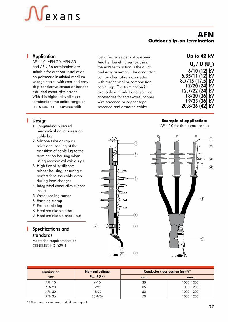
37
6/10 (12) kV6.35/11 (12) kV
8.7/15 (17.5) kV12/20 (24) kV
12.7/22 (24) kV18/30 (36) kV19/33 (36) kV
20.8/36 (42) kV
Up to 42 kV
Termination
type
Nominal voltage
U0 /U (kV)
Conductor cross-section (mm2) *
min. max.
AFN 10
AFN 20
AFN 30
AFN 36
6/10
12/20
18/30
20.8/36
25
35
50
50
1000 (1200)
1000 (1200)
1000 (1200)
1000 (1200)
Design1. Longitudinally sealed mechanical or compression cable lug 2. Silicone tube or cap as additional sealing at the transition of cable lug to the termination housing when using mechanical cable lugs3. High flexibility silicone rubber housing, ensuring a perfect fit to the cable even during load changes 4. Integrated conductive rubber insert5. Water sealing mastic6. Earthing clamp 7. Earth cable lug8. Heat-shrinkable tube9. Heat-shrinkable break-out
3
1
2
8
4
9
Specifications andstandardsMeets the requirements ofCENELEC HD 629.1
1
2
3
4
5
7
6
Example of application:AFN 10 for three-core cables
AFNOutdoor slip-on termination
U0 / U (Um )
* Other cross-section are available on request.
ApplicationAFN 10, AFN 20, AFN 30 and AFN 36 termination are suitable for outdoor installation on polymeric insulated medium voltage cables with extruded easy strip conductive screen or bonded extruded conductive screen. With this highquality silicone termination, the entire range of cross-sections is covered with
just a few sizes per voltage level. Another benefit given by using the AFN termination is the quick and easy assembly. The conductor can be alternatively connected with mechanical or compression cable lugs. The termination is available with additional splitting accessories for three-core, copper wire screened or copper tape screened and armored cables.

38
15-0
5-20
14
Nexans Power Accessories Germany GmbH • Ferdinand-Porsche-Str. 12 • 95028 Hof/Saale • Phone: +49 9281 8306-0E-Mail: [email protected] • www.nexans-power-accessories.com
Kit contents• 3 termination housings• 3 mechanical or compression cable lugs for the conductor
• 3 mechanical or compression screen wire cable lugs• Installation instructions• Silicone grease• Assembly incidentals
Nominal voltageU0 /U(kV)
Conductor cross-sec-tion (mm2)
Dia. over core insulation
(mm)Number of sheds
L(mm)
Dia. D(mm)
Creep-age
distance(mm)
Ordering part number
min. max. min. max.
6/10
25
120
300
630
95
240
500
800
12.7
19.2
27.4
34.0
39.0
46.0
20.8
28.4
36.4
45.0
50.0
58.0
3
3
3
4
7
7
210
210
210
240
330
405
90
96
105
118
127
127
369
365
360
462
680
755
3 x AFN 10 Gr.1
3 x AFN 10 Gr.2
3 x AFN 10 Gr.3
3 x AFN 20 Gr.4
3 x AFN 30 Gr.4
3 x AFN 36 Gr.61000
1200
12/20
35
95
300
400
630
1000
70
240
500
630
800
1200
18.3
22.5
31.0
34.0
39.0
46.0
23.5
33.0
41.0
45.0
50.0
58.0
4
4
4
4
7
7
240
240
240
240
330
405
100
112
118
118
127
127
480
499
462
462
680
755
3 x AFN 20 Gr.1
3 x AFN 20 Gr.2
3 x AFN 20 Gr.3
3 x AFN 20 Gr.4
3 x AFN 30 Gr.4
3 x AFN 36 Gr.6
18/30
50
95
240
400
630
70
240
400
630
1200
23.8
27.1
31.5
39.0
46.0
28.4
37.6
42.8
50.0
58.0
6
6
6
7
7
300
300
300
330
405
115
115
127
127
127
695
694
718
680
755
3 x AFN 30 Gr.1
3 x AFN 30 Gr.2
3 x AFN 30 Gr.3
3 x AFN 30 Gr.4
3 x AFN 36 Gr.6
20.8/36
**
50
95
240
400
630
70
240
400
630
1200
23.8
27.1
31.5
39.0
46.0
28.4
37.6
42.8
50.0
58.0
6
6
6
7
7
300
300
300
330
405
115
115
127
127
127
695
694
718
680
755
3 x AFN 30 Gr.1
3 x AFN 30 Gr.2
3 x AFN 30 Gr.3
3 x AFN 30 Gr.4
3 x AFN 36 Gr.6
Note: The classification does only apply for polymeric insulated XLPEcables (dimensions acc. to DIN VDE 0276 620) with extruded conductive screen. Please contact our sales representative, when using other cable types.
** Since the dimensions for cables at voltage level 20.8/36 (42) kV are not yet standardised, the conductor cross-sections and their assignment of diameters over core insulation given in the table are to be consideredapproximate values. When ordering accessories, we would like to ask you to indicate the checked diameters over core insulation.
Ordering instructionsIndicate the part numberwhen ordering (see table).
Order example:1 AFN 20 kit for 12/20kV, for 95-240 mm² withmechanical cable lug (palmhole diameter 13 mm).Order according to table 2:1 kit – AFN 20 size 2 with part number 48793.
L
Ø B
Ø D
Table 1 - Classification and dimensions
For use with copper wire screened cables. No earthing
device is necessary.
For use withcopper tape
screened cables. Order: Kit MT.
For use with three-core cables. Please contact our
representative.
For use withother cable types.Please contact our
representative.
Can be supplied with all common types of cable lugs.

39Nexans Power Accessories Germany GmbH • Ferdinand-Porsche-Str. 12 • 95028 Hof/Saale • Phone: +49 9281 8306-0E-Mail: [email protected] • www.nexans-power-accessories.com
Table 2 - Ordering part number
AFNOutdoor slip-on termination
Conductor cross-sec-tion (mm2)
Dia. over core insulation (mm)
Ordering part number (1 Kit = 3 Items)Termination
type(Kit)
with mechanical connector with compression connector
min. max.Ordering
part numberDia. B Al - rm(V) Cu - rm(V) Dia. B
Nominal voltage U0 /U 6/10 kV
25
12.7 20.8 52190 13
52196 52197 13
AFN 10 Gr. 135 52198 48330 1350 52199 49750 1370 52200 49877 1395 52201 48939 13120
19.2 28.4 52191 13
52202 47989 13
AFN 10 Gr. 2150 45599 45730 13185 52203 52204 17240 45384 45090 17300
27.4 36.4 52194 1752205 47969 17
AFN 10 Gr. 3400 52206 45733 17500 48084 44691 17630 34.0 45.0 54863 21 54879 54864 21 AFN 20 Gr. 4800 57576 54865 211000 39.0 50.0 57242 21 57243 57244 21 AFN 30 Gr. 41200 On request
Nominal voltage U0 /U 12/20 kV
3518.3 23.5 51355 13
49628 45481 13AFN 20 Gr. 150 45315 45365 13
70 49624 45521 1395
22.5 33.0 48793 13
44564 45109 13
AFN 20 Gr. 2120 49625 45749 13150 44189 44668 13185 49626 44643 17240 44340 44487 17300
31.0 41.0 59080 1745477 45403 17
AFN 20 Gr. 3400 45598 45164 17500 49630 44563 17400
34.0 45.0 54965 1754966 59081 17
AFN 20 Gr. 4500 54866 59082 17630 59084 59083 21630 39.0 50.0 57245 21 57246 57248 21 AFN 30 Gr. 4800 57247 57249 211000 46.0 58.0 59758 21 57567 57568 21 AFN 36 Gr. 61200 On request
Nominal voltage U0 /U 18/30 kV50 23.8 28.4 51367 13 49635 45140 13 AFN 30 Gr. 170 49637 49636 1395
27.1 37.6 51369 13
48677 49638 13
AFN 30 Gr. 2120 49640 49639 13150 49641 48085 13185 48002 45396 17240 44670 44669 17240
31.5 42.8 52213 1752220 52219 17
AFN 30 Gr. 3300 49642 44791 17400 45235 48108 17400
39.0 50.0 57273 1757274 57275 17
AFN 30 Gr. 4500 48577 48580 17630 48578 48581 21630
46.0 58.0 54857 2154917 54875 21
AFN 36 Gr. 6800 54873 54876 211000 54874 54877 211200 On request
Nominal voltage U0 /U 20,8/36 kV
50 23.8 28.4 57250 13 57253 57263 13 AFN 30 Gr. 170 57254 57264 1395
27.1 37.6 57251 13
57255 57265 13
AFN 30 Gr. 2120 57256 57266 13150 57257 57267 13185 57258 57268 17240 57259 57269 17240
31.5 42.8 57252 1757260 57270 17
AFN 30 Gr. 3300 57261 57271 17400 57262 57272 17400
39.0 50.0 57276 1757277 57280 17
AFN 30 Gr. 4500 57278 57281 17630 57279 57282 21630
46.0 58.0 54860 2154886 54897 21
AFN 36 Gr. 6800 54887 54898 211000 54888 54899 211200 On request
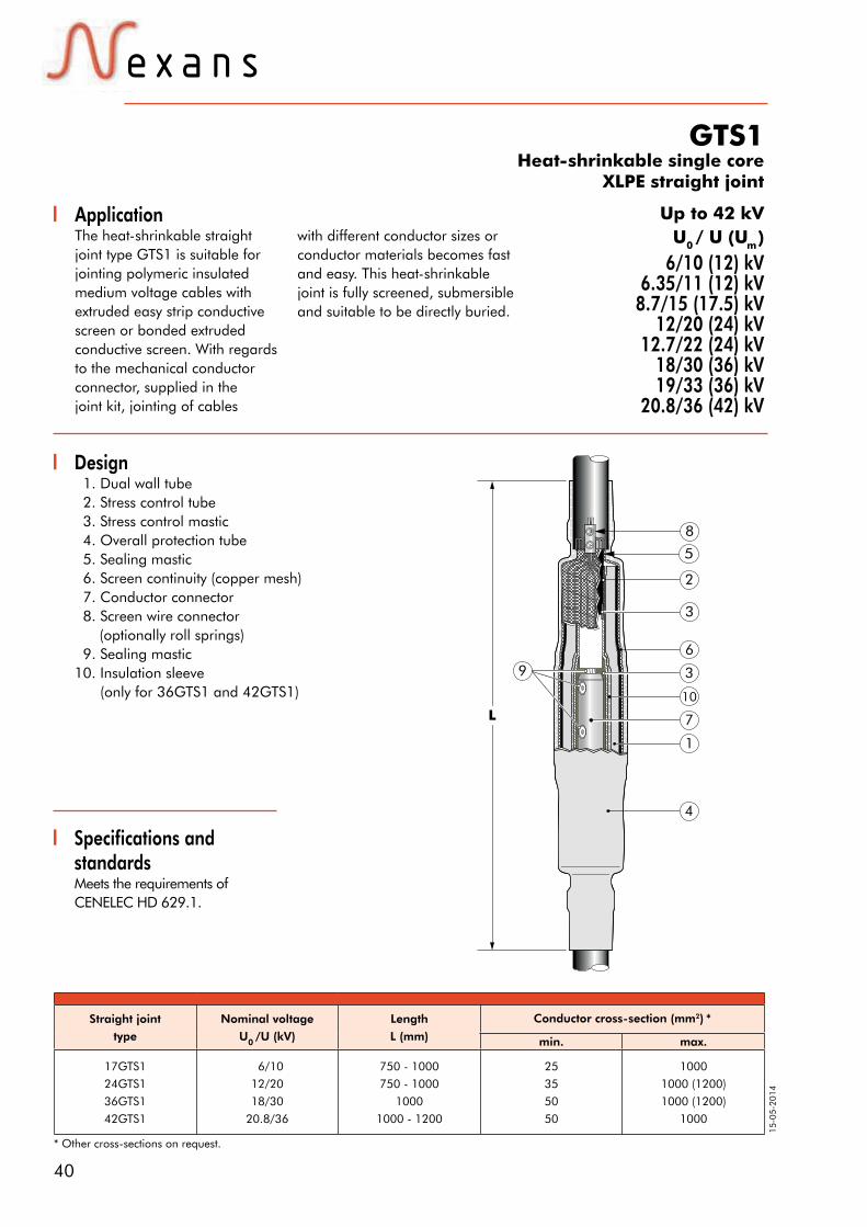
40
15-0
5-20
14
6/10 (12) kV6.35/11 (12) kV
8.7/15 (17.5) kV12/20 (24) kV
12.7/22 (24) kV18/30 (36) kV19/33 (36) kV
20.8/36 (42) kV
Specifications and standardsMeets the requirements ofCENELEC HD 629.1.
Design 1. Dual wall tube 2. Stress control tube 3. Stress control mastic 4. Overall protection tube 5. Sealing mastic 6. Screen continuity (copper mesh) 7. Conductor connector 8. Screen wire connector (optionally roll springs) 9. Sealing mastic10. Insulation sleeve (only for 36GTS1 and 42GTS1)
Up to 42 kV
GTS1Heat-shrinkable single core
XLPE straight joint
Straight joint
type
Nominal voltage
U0 /U (kV)
Length
L (mm)
Conductor cross-section (mm2) *
min. max.
17GTS1
24GTS1
36GTS1
42GTS1
6/10
12/20
18/30
20.8/36
750 - 1000
750 - 1000
1000
1000 - 1200
25
35
50
50
1000
1000 (1200)
1000 (1200)
1000
5
2
3
10
7
1
4
76
L
8
9
3
U0 / U (Um ) ApplicationThe heat-shrinkable straightjoint type GTS1 is suitable forjointing polymeric insulatedmedium voltage cables withextruded easy strip conductivescreen or bonded extrudedconductive screen. With regardsto the mechanical conductorconnector, supplied in the joint kit, jointing of cables
with different conductor sizes or conductor materials becomes fast and easy. This heat-shrinkable joint is fully screened, submersible and suitable to be directly buried.
* Other cross-sections on request.

41Nexans Power Accessories Germany GmbH • Ferdinand-Porsche-Str. 12 • 95028 Hof/Saale • Phone: +49 9281 8306-0E-Mail: [email protected] • www.nexans-power-accessories.com
** Applicable for aluminium conductors up to 150 mm², not applicable for copper conductors.
Kit contentsThe complete GTS1 joint kit comprises the following components:
The kit also comprises:+ mechanical conductor connector+ mechanical screen wire connector+ installation instructions+ field control mastic+ wipers+ silicone grease+ assembly incidentals
+
Sealing mastic
Stress control tube
Insulation sleeve(only for 36GTS1
and 42GTS1)
Stress control mastic
=+ + GTS1++
Overall protection tube
Copper meshtape
++
Dual wall tube
Mechanicalconnector
Straight joint type
Nominal voltage
U0 /U (kV)
Conductor cross-section
(mm²)
Conductor cross-section (mm2)
25 35 50 70 95 120 150 185 240 300 400 500 630 800 1000
17GTS1.95 6/10 25 95 52606
17GTS1.240 6/10 95 240 52607
17GTS1.400 6/10 240 400 52608
17GTS1.630 6/10 400 630 52609
17GTS1.1000 6/10 800 1000 53504
24GTS1.50 12/20 35 50 52610
24GTS1.240 12/20 50 150 52611**
24GTS1.240 12/20 50 240 52612
24GTS1.240 12/20 95 240 49758
24GTS1.300 12/20 120 300 58023
24GTS1.400 12/20 185 400 52613
24GTS1.630 12/20 400 630 52615
24GTS1.1000 12/20 630 1000 53661
36GTS1.95 18/30 50 95 52616
36GTS1.240 18/30 95 240 52618
36GTS1.500 18/30 185 400 52619
36GTS1.800 18/30 400 630 52620
36GTS1.1000 18/30 630 1000 59209
42GTS1.95 20.8/36 50 95 57225
42GTS1.150 20.8/36 50 150 57226**
42GTS1.240 20.8/36 95 240 59859
42GTS1.400 20.8/36 185 400 57227
42GTS1.630 20.8/36 400 630 57228
42GTS1.1000 20.8/36 630 1000 57229
Ordering instructionsSelect the straight joint type corresponding to both system voltage and conductor cross-section.
Note: The classification does only apply for polymeric insulated XLPE cables (dimensions acc. to DIN VDE 0276 620) with extruded conductive screen. Please contact our representative, when using other cable types.
Order example:Heat-shrinkable straight joint type 24GTS1.240 for XLPE cable 12/20 kV70-240 mm² conductor cross-section.Order number: 52612
For use with copper wire screened cables. No further earthing device is necessary.
For use with other cables types.
Please contact our representative.
Jointing cables of different sizes possible.
For use with copper tape screened cables, endorse "A"
to the part number. (e.g. 24GTS1.240A)
For use with three-core cables: see GTS3.
Can be used with all common types of
conductor connectors.

42
15-0
5-20
14
Up to 36 kV
Straight joint type
Nominal voltage
U0 /U (kV)
Dia. over core
insulation (mm)Dia. over outer sheath
(mm)
Conductor cross-
section (mm2)L
(mm)min. max. min. max.
24CSJ-2 Gr. 124CSJ-2 Gr. 2
6/106/10
1823
2333
max. 46max. 46
95150
150240 (300)*
ca. 750ca. 750
24CSJ-2 Gr. 124CSJ-2 Gr. 2
24CSJ - 3
12/2012/2012/20
182330
233345
max. 46max. 46max. 57
3595240
70240 (300)*
630
ca. 750ca. 750ca. 850
36CSJ-2 18/30 23 36 max. 48 50 240 ca. 750
36CSJ-3 18/30 30 50 max. 57 185 400 (630)* ca. 850
Design1. Extruded triple layer EPDM rubber body2. Two layer plate with a semi- conductive and a field control mastic layer3. Overall protective EPDM cover4. Field control mastic5. Water sealing mastic6. Copper stocking7. Self-adhesive copper tape8. Traceability tag9. Mechanical conductor connector
CSJCold-shrinkable straight joint
for single core XLPE cables
6/10 (12) kV6.35/11 (12) kV
8.7/15 (17.5) kV12/20 (24) kV18/30 (36) kV19/33 (36) kV
L
7
1
8
3
6
2
4
4
7
5
5
9
U0 / U (Um )
Specifications and standardsThe cold-shrinkable CSJjoint meets the requirements of CENELEC HD 629.1.
ApplicationThe cold-shrinkable straightjoint type CSJ is suitable forjointing polymeric insulatedmedium voltage cables withextruded easy strip conductivescreen or bonded extrudedconductive screen. With regardsto the mechanical conductorconnector, supplied in the joint kit, jointing of cables
with different conductor sizes or conductor materials becomes fast and easy. This cold-shrinkable joint is fully screened, submersible and suitable to be directly buried.
Technical characteristicsAll joint bodies are tested for AC withstand prior to leaving the factory.
* Conductor sizes in clamps currently available with compression joint.

43Nexans Power Accessories Germany GmbH • Ferdinand-Porsche-Str. 12 • 95028 Hof/Saale • Phone: +49 9281 8306-0E-Mail: [email protected] • www.nexans-power-accessories.com
Kit contentsA typical complete cold-shrinkable joint kit comprises the following components:
Ordering instructionsSelect the straight joint type corresponding to the cabletype and dia. over core insulation.
Order example:Cold-shrinkable straight jointNominal voltage 12/20 kV,Conductor cross-section 95-240 mm² Dia. over core insulation 23-33 mm²Order number: 48136
1 x CSJCold-shrinkable
joint1 x Two-layer
plate
6 x Field control mastic
strip2 x Self-adhesive
copper tape
** Please consider the maximum outer cable diameter
*** Applicable for aluminium conductors up to 150 mm², not applicable for copper conductors.
The kit also comprises:+ installation instructions+ silicone grease+ white pen+ gloves+ assembly gauge+ adhesive tape+ rubber rings+ assembly incidentals
+ + +24CSJ
or
36CSJ=
Straight joint type
Nominal voltageU0 /U(kV)
Conductor cross-section (mm2) Dia. over
core insulation
(mm²)
Dia. over outer sheath
(mm)35 50 70 95 120 150 185 240 300 400 500 630 800 1000
24CSJ-2 Gr. 1 6/10 53752*** 18-23 max. 46
24CSJ-2 Gr. 2 6/10 59088 23-33 max. 46
24CSJ-2 Gr. 1 12/20 59087 18-23 max. 46
24CSJ-2 Gr. 2 12/20 48136** 23-33 max. 46
24CSJ-3 12/20 52650 30-54 max. 57
24CSJ-3 12/20 51800** 30-54 max. 57
36CSJ-2 Gr. 2 18/30 53738*** 23-36 max. 48
36CSJ-2 Gr. 2 18/30 53737 23-36 max. 48
36CSJ-3 18/30 57216 30-50 max. 57
36CSJ-3 18/30 57217** 30-50 max. 57
1 x Mechanicalconnector
+
For use with Alupe cables. Please contact
our representative
Can be supplied as stop joint. Please contact our representative
For use with other cable types. Please contact our representative
For use with three-core cables.
See TT-24CSJ.
For use with fabric tape (graphite) screened cables.
Order additional semi-conductive tape.

44
15-0
5-20
14
24CSJ-SCold-shrinkable compact single core straight joint
Up to 24 kVApplicationThe cold-shrinkable straightjoint 24CSJ-S is used for jointingmedium-voltage cables with a copper wired screen and with extruded conductive screen.This product can be installedwhere installation space islimited. With regards to the mechanical conductorconnector, supplied in the
Technical characteristics All joint bodies are tested forAC withstand prior to leavingthe factory.
Design 1. Extruded triple layer EPDM rubber body 2. Two layer plate with a semiconductive and a field control mastic layer 3. Overall protective EPDM cover 4. Field control mastic 5. Water sealing mastic 6. Copper stocking 7. Self-adhesive copper tape 8. Traceability tag 9. Mechanical conductor connector
6/10 (12) kV6.35/11 (12) kV
8.7/15 (17.5) kV12/20 (24) kV
12.7/22 (24) kV
Specifications andstandardsThe cold-shrinkable 24CSJ-Sjoint meets the requirements ofCENELEC HD 629.1.
Cold-shrinkable
straight joint type
Nominal voltage
U0 /U (kV)
Dia. over outer
sheath (mm)
Dia. over core
insulation (mm)
Conductor cross-section
(mm²)
max. min. max. min. max.
24CSJ-S/M70-2406/10
12/20
48
48
18
18
36
36
95
70
240
240
24CSJ-S/M120-3006/10
12/20
48
48
18
18
36
36
120
120
300
300
3
7
600 mm
2
9
1
7
5
7
4
5
6
4
8
joint kit, jointing of cableswith different conductorsizes or conductor materialsbecomes fast and easy. Thiscold-shrinkable joint is fullyscreened, submersible andsuitable to be directly buried.
U0 / U (Um )

45Nexans Power Accessories Germany GmbH • Ferdinand-Porsche-Str. 12 • 95028 Hof/Saale • Phone: +49 9281 8306-0E-Mail: [email protected] • www.nexans-power-accessories.com
Kit contentsThe complete cold-shrinkablejoint kit comprises the followingcomponents:
The kit also comprises:+ installation instructions+ silicone grease+ wipers+ installation hook+ assembly gauge+ assembly incidentals
24CSJ-S
1 x 24CSJ-SCold-shrinkable compact joint
2 x Self-adhesive coppertape
2 x Masticplates
1 x Mechanical connector
1 x Two-layer plate
2 x Mastic strip
(+ 4 for sealing the screen area)
1 x Watersealing
mastic strip
One box contains everything you need to joint your cables.
380
mm
Ordering part number
Nominal voltage
U0 /U (kV)
Conductor cross-section (mm2) Dia. over core insulation
(mm)
Dia. over outer sheath(mm)35 50 70 95 120 150 185 240 300
24CSJ-S/M70-2406/10
12/2024CSJ-S/M70-240
18-36 max. 48Art.-Nr. 54567
24CSJ-S/M120-3006/10
12/2024CSJ-S/M120-300
Art.-Nr. 57215 18-36 max. 48
For use with other cable types. Please contact our representative
Can be supplied as a stop joint. Please contact
our representative.
For use with fabric tape (graphite) screened cables.
Order additional semi-conductive tape.
For use with copper wire screened cables. No further earthing device is necessary.
Compact 24CSJ-S - Highlights• Compact dimensions allow the same easy installation in half the space• All components are pre-assembled on a support tube, which is pulled out in a single movement, enabling an easy and fast installation
• A triple-extruded body in a pre-installed joint reduces the number of components in the kit• Purpose designed EPDM rubber with high recovery forces result in tight electrical interfaces and perfect sealing• All our products are subjected to extensive testing from the time they enter our plant as raw material until they leave as finished products• This cold shrinkable joint exceeds international performance standards including CENELEC HD 629 and IEC 60502 for joints and IEC 61238 for mechanical and crimp connectors• No special tools or flame required• One of the features of our cold shrinkable joint is the screen connection system. By using the pressure of the outer protection sleeve, the copper stocking integrated in the joint is kept against the metallic screen from the cable, ensuring a stable connection• This joint can be energised immediately after installation
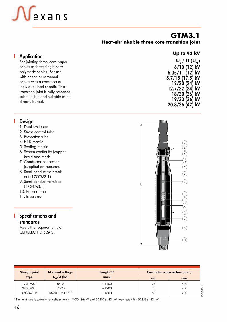
46
15-0
5-20
14
Specifications andstandardsMeets the requirements ofCENELEC HD 629.2.
GTM3.1Heat-shrinkable three core transition joint
ApplicationFor jointing three-core papercables to three single corepolymeric cables. For usewith belted or screenedcables with a common or individual lead sheath. This transition joint is fully screened, submersible and suitable to be directly buried.
Straight joint
type
Nominal voltage
U0 /U (kV)
Length "L"
(mm)
Conductor cross-section (mm2)
min max
17GTM3.1
24GTM3.1
42GTM3.1*
6/10
12/20
18/30 + 20.8/36
~1200
~1200
~1800
25
35
50
400
400
400
Design1. Dual wall tube2. Stress control tube3. Protection tube 4. Hi-K mastic5. Sealing mastic6. Screen continuity (copper braid and mesh)7. Conductor connector (supplied on request).8. Semi-conductive break- out (17GTM3.1) 9. Semi-conductive tubes (17GTM3.1)10. Barrier tube11. Break-out
3
3
8
10
5
4
6
9
7
1
2
4
5
11
L
U0 / U (Um )
Up to 42 kV
6/10 (12) kV6.35/11 (12) kV
8.7/15 (17.5) kV12/20 (24) kV
12.7/22 (24) kV18/30 (36) kV19/33 (36) kV
20.8/36 (42) kV
* The joint type is suitable for voltage levels 18/30 (36) kV and 20.8/36 (42) kV (type tested for 20.8/36 (42) kV)

47Nexans Power Accessories Germany GmbH • Ferdinand-Porsche-Str. 12 • 95028 Hof/Saale • Phone: +49 9281 8306-0E-Mail: [email protected] • www.nexans-power-accessories.com
Kit contentsThe complete GTM3.1 jointkit comprises the followingcomponents:
The kit also comprises:+ installation instructions+ mechanical conductor connector+ mechanical screen wire cable lug+ roll springs+ assembly incidentals
Semi-conductive tube GT5
(17GTM3.1)
ProtectiontubeGT4
(all types)
= GTM3.1
Dual walltube
GT25(all types)
Barrier tube
GT10(all types)
Insulation sleeve
(42GTM3.1)
Break-out(all types)
Black stresscontrol tube
GT1(all types)
1x Semi-conductivebreak-out
36TTS(17GTM3.1)
Ordering instructionsPlease indicate the part numberwhen ordering (see table).Select the order designation ofthe straight joint according to thecable type used and the diameter over core insulation.
Order example:For a paper-insulated beltedcable with 6/10 kV, 3x150 mm²on an XLPE-insulated single-corecable with 6/10 kV, 120 mm².Order according to the table:17GTM3.1.240 part number 59854.
Straight joint type
Nominal voltageU0 /U (kV)
Conductor cross-section (mm²) Ordering part
numbermin max
17GTM3.1.9517GTM3.1.24017GTM3.1.400
6/106/106/10
2595240
95240400
572885985457289
24GTM3.1.5024GTM3.1.24024GTM3.1.30024GTM3.1.400
12/2012/2012/2012/20
3570120185
50240300400
57290572915820957292
42GTM3.1.95*42GTM3.1.150*42GTM3.1.240*42GTM3.1.400*
18/30 + 20.8/3618/30 + 20.8/3618/30 + 20.8/3618/30 + 20.8/36
5095150240
95150240400
57293572945729557296
* The joint type is suitable for voltage levels 18/30 (36) kV and 20.8/36 (42) kV (type tested for 20.8/36 (42) kV)
+++++++
When jointing cables of different sizes., please
contact our representative.
For use with other cable types. Please contact our
representative

48
15-0
5-20
14
Up to 42 kV
READY-TO-INSTALL, PRE-ASSEMBLED CABLESInterface A to F connectors and terminations
6/10 (12) kV6.35/11 (12) kV
8.7/15 (17.5) kV12/20 (24) kV
12.7/22 (24) kV18/30 (36) kV19/33 (36) kV
20.8/36 (42) kV
ApplicationPre-assembled cables arepolymeric insulated mediumvoltage cables, equipped withconnectors and terminations.They can be used forconnecting transformers andswitchgears. We manufacturethe pre-assembled cablesspecifically customized interms of cable length and type
Flexible cablesPre-assembled flexible cables,such as NTMCGCWÖU, areused in stations with little space,where the bending radii cannotbe met with XLPE-insulatedcables.Due to their design• Fine-wire, tin-plated copperconductor• Ethylene-propylene rubber(EPR) insulation• Fine-wire shield• Polychloroprene (flame-andoil-resistant) outer sheath,these flexible cables can belaid with minimum bendingradii of 5 times the outside
U0 / U (Um ) of accessories. The cablesand flexible cables, primarilychecked by us, are assembled withdifferent conductor cross-sectionsand accessories, depending oncustomer’s application.
CablesPre-assembled cables typeN(A)2XS(2)Y are used wherethe space conditions insideequipment allow the minimumcable bending radius of 15times its outside diameter.
diameter. In terms of theircurrent-carrying capacity inservice and in the event ofshort-circuit current, EPR-insulated cables are almostequivalent to XLPE-insulatedcables.
Accessory ASee table for accessoryselection.
Accessory BSee table for accessoryselection.
Dimensioning basisWhen dimensioning the preassembled cable length, wetake the center points of bothcable accessories as the basis.When indicating the length ofthe shield wire, please alsospecify whether the shield wireshould be lead out on one orboth sides.
Elbow connectorK158LR
Indoor termination AIN20
Dimensioning basis for
wire- / cable length

49Nexans Power Accessories Germany GmbH • Ferdinand-Porsche-Str. 12 • 95028 Hof/Saale • Phone: +49 9281 8306-0E-Mail: [email protected] • www.nexans-power-accessories.com
U0 /U (kV)
6/10
U0 /U (kV)
12/20
U0 /U (kV)
18/30
U0 /U (kV)
20.8/36 * Length of
shield wireL 1 L 2 L 3 L 1 L 2 L 3 L 1 L 2 L 3 L 1 L 2 L 3
Conductor/
cable type
Conductor/
cable length
Accessory A
Accessory B
Partial discharge
sample testyes / no yes / no yes / no yes / no
AC withstand test yes / no yes / no yes / no yes / no
Example request:Please fill in what is applicable.
* If you do not indicate the length of the shield wire, we will assume a length of 500 mm for accessory "A" and "B".
Type Design Interface Material Assembly technique
(K)158LR(/G)
(K)152SR(/G)
(K)(M)400LR/G
(K)(M)430TB/G
(K)(M)(P)484TB/G
(K)(M)(P)804PB/G
(K)(M)(P)489TB/G
(K)(M)(P)809PB/G
(K)676LRA/G
775LR
(K)(M)(P)944TB/G
AIN 10
AIN 20
AIN 30
AIN 36
AFN 10
AFN 20
AFN 30
AFN 36
Elbow connector
Straight connector
Elbow connector
Compact tee connector
Compact tee connector
Coupling connector
Compact tee connector
Coupling connector
Separable tee connector
Separable tee connector
Compact tee connector
Indoor termination
Indoor termination
Indoor termination
Indoor termination
Outdoor termination
Outdoor termination
Outdoor termination
Outdoor termination
A
A
B
C
C
C
C
C
D
E
F
-
-
-
-
-
-
-
-
EPDM
EPDM
EPDM
EPDM
EPDM
EPDM
EPDM
EPDM
EPDM
EPDM
EPDM
EPDM
Silicone
Silicone
Silicone
Silicone
Silicone
Silicone
Silicone
Slip-on technology
Slip-on technology
Slip-on technology
Slip-on technology
Slip-on technology
Slip-on technology
Slip-on technology
Slip-on technology
Slip-on technology
Slip-on technology
Slip-on technology
Slip-on technology
Slip-on technology
Slip-on technology
Slip-on technology
Slip-on technology
Slip-on technology
Slip-on technology
Slip-on technology
Accessory selection:We will also assemble accessories that are not listed here.

50
15-0
5-20
14
C - SERIESMechanical cable lugs, type C
ApplicationUsing mechanical cable lugsallows a larger, multirange conductor cross-section even for terminations. The mechanical cable lugs are generally tinplated and are offered with different palm holes, just like compression cable lugs.
Design
a
D
L
d
C95-240, centric with shear-off- head bolts
MaterialConnector Body: high strength aluminum alloy Bolts: brass, tin-plated, with inner and outer hexagon or aluminum alloySurfaceConnector Body: tin-plated
Center Rings Center rings: are enclosed for centric conductor positioning.
C...
C70-240
Advantages· Simple, quick installation: With common commercially available inner and outer hexagon tools or an approved impact wrench.· Minimum storage costs: The cross-sectional area from 16 mm² to 1000 mm² is covered by just 4 types of cable lugs.
· Universal applicability: Can be used for copper and aluminium conductors according to EN 60228 classes 1 & 2. For use of our mechanical connectors with class 5 flexible copper conductors, please contact us.· Proven quality: Tested for class 2 conductors according to IEC 61238-1, in failure-free operation for more than 15 years.
1) Dimension d2=26
Cat. no. Conductor cross-section Aluminium (mm²)
Conductor cross-section Copper (mm²)
Number of bolts
Dimensions (mm)
Palm hole Dia.(mm)
Tool / outer and inner hexagon
rm(v) re sm rm(v) sm L d1 D a
C16-95 x 1216-95 16-95 25-70 16-95 25-70 1 60 12.5 24 32
13SW13 & SW6
C16-95 x 16 17
C50-150 x 1225-150 25-150 35-120 25-120 35-120 1 79 15.5 30 35
13SW17 & SW6
C50-150 x 16 17
C70-240 x 1270-240 70-240 70-240 70-240 70-240 2 93.5 221) 35 56
13SW19 & SW6
C70-240 x 16 17
C95-240 x 1295-240 95-240 95-185 95-240 95-185 2 95 20 33 56
13SW19 & SW6
C95-240 x 16 17
C120-300 x 12120-300 120-300 120-240 120-300 120-240 2 105 25 38 67
13SW22 & SW6
C120-300 x 16 17
C185-400 x 12185-400 185-400 185-300 185-400 185-300 3 120 26 42 82
13SW22 & SW6
C185-400 x 16 17
C300-500 x 12
300-500 300-500 300-400 300-500 300-400 3 130 34 52 94
13
SW24 & SW8C300-500 x 16 17
C300-500 x 20 21
C400-630 x 12
400-630 400-630 400-500 400-630 400-500 3 130 34 52 94
13
SW24 & SW8C400-630 x 16 17
C400-630 x 20 21
C630-1000 x 20 630-1000 630-1000 630-1000 4 165 41 65 105 21 SW22 & SW8

51Nexans Power Accessories Germany GmbH • Ferdinand-Porsche-Str. 12 • 95028 Hof/Saale • Phone: +49 9281 8306-0E-Mail: [email protected] • www.nexans-power-accessories.com
Cable lug type Ordering part number
C16-95 x 12
C16-95 x 16
G6502 40 20
G6502 40 33
C50-150 x 12
C50-150 x 16
G6502 40 09
G6502 40 32
C70-240 x 12
C70-240 x 16
G6502 40 36
G6502 40 40
C95-240 x 12
C95-240 x 16
G6502 40 10
G6502 40 17
C120-300 x 12
C120-300 x 16
G6502 40 23
G6502 40 26
C185-400 x 12
C185-400 x 16
G6502 40 30
G6502 40 19
C300-500 x 12
C300-500 x 16
G6502 40 34
G6502 40 37
C400-630 x 12
C400-630 x 16
C400-630 x 20
G6502 40 28
G6502 40 31
G6502 40 29
C630-1000 x 20 G6502 51 10
Ordering instructionsPlease indicate the part num-ber when ordering (see table). The centring rings or centring inserts are part of the scope of delivery.
Order example:1 mechanical cable lug, for 95-240 mm², palm hole: 17 mm.Order according to thetable: 1 C95-240 x 16 with part number G6502 40 17.
Specifications andstandardsThe mechanical connectorshave been tested according toIEC 61238-1 or VDE 0220 part100 respectively.
Technical detailsThe bolt has an inner and outer hexagon. Both are related to the various shear-off-areas of the bolt and their different tor-que moments.
The torque moments follow the rule that large conductor cross sections need high torque moments and smaller cross sections need lower torque moments.
The installation instruction describes the use of both hexagons and of the various center rings and inserts, for the respective conductor types.
Centring of the conductorFor the centric position ofsmaller conductor cross-sections in the conductorchannel, we use centring ringsthat must be pressed all theway into the channel of thecable lug before assembling
the corresponding conductor cross-section. The centring rings differ in colour and are assigned to the respective type of conductor. Appropriate assembly instructions describe
which type of conductor the centring rings are to be used for. The conductor is centred using a centring insert in the case of the largest cross-sectional area.
It is possible to connectdifferent conductor cross-
sections.
Cu
Al
Can be supplied with all common types of
cable lugs.
It is possible to connectdifferent conductor
materials.
We use centring rings forthe centric position of small conductor cross-
sections.
Can be used for allconductor shapes.
Product rangeA complete overview of ourGPH products (ferrules & lugs) can be found in catalogue modules A, B, C and D.

52
15-0
5-20
14
Cable lugs compression type, Cu Standard type, with and without inspection hole
ApplicationFor isolated, non-compacted copper conductors.
DesignMaterialConnector body: CopperPalm: plan stamped
Surface: tin-platedKU-L: without inspection holeKU-L-S: with inspection hole
The compression of the KU-L Series does not accord to the DIN requirements. Special compression tools are available on request.
KU-L KU-L-S
Cat. no. Conductor cross-section(mm²)strand.
Dimensions(mm)
Flat hole diameter
(mm)
Weight 100 pcs. (approx. kg)
KU-L KU-L-S d a l b
6 x 5 KU-L6 x 6 KU-L6 x 8 KU-L6 x 10 KU-L
6 x 5 KU-L-S6 x 6 KU-L-S6 x 8 KU-L-S6 x 10 KU-L-S
6 3.5 9
21212121
10.511.515.517.0
5.4 6.5 8.510.5
0.40.40.40.5
10 x 5 KU-L10 x 6 KU-L10 x 8 KU-L10 x 10 KU-L
10 x 5 KU-L-S10 x 6 KU-L-S10 x 8 KU-L-S10 x 10 KU-L-S
10 4.5 9
212123
25.5
12.012.014.517.0
5.5 6.5 8.510.5
0.40.40.40.5
16 x 5 KU-L16 x 6 KU-L16 x 8 KU-L16 x 10 KU-L16 x 12 KU-L
16 x 5 KU-L-S16 x 6 KU-L-S16 x 8 KU-L-S16 x 10 KU-L-S16 x 12 KU-L-S
16 5.5 12
2626283032
12.012.013.517.020.0
5.5 6.5 8.510.513.0
0.50.70.80.80.8
25 x 6 KU-L25 x 8 KU-L25 x 10 KU-L25 x 12 KU-L
25 x 6 KU-L-S25 x 8 KU-L-S25 x 10 KU-L-S25 x 12 KU-L-S
25 7.0 13
27293334
14.016.017.520.0
6.5 8.510.513.0
1.01.01.11.0
35 x 6 KU-L35 x 8 KU-L35 x 10 KU-L35 x 12 KU-L
35 x 6 KU-L-S35 x 8 KU-L-S35 x 10 KU-L-S35 x 12 KU-L-S
35 8.5 15
31323437
18.018.018.022.0
6.5 8.510.513.0
1.01.01.11.0
Technical noteSector shaped conductors must be rounded with special dies.
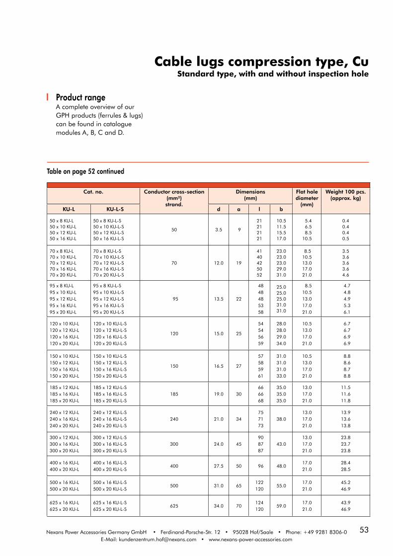
53Nexans Power Accessories Germany GmbH • Ferdinand-Porsche-Str. 12 • 95028 Hof/Saale • Phone: +49 9281 8306-0E-Mail: [email protected] • www.nexans-power-accessories.com
Cable lugs compression type, Cu Standard type, with and without inspection hole
Cat. no. Conductor cross-section(mm²)strand.
Dimensions(mm)
Flat hole diameter
(mm)
Weight 100 pcs. (approx. kg)
KU-L KU-L-S d a l b
50 x 8 KU-L50 x 10 KU-L50 x 12 KU-L50 x 16 KU-L
50 x 8 KU-L-S50 x 10 KU-L-S50 x 12 KU-L-S50 x 16 KU-L-S
50 3.5 9
21212121
10.511.515.517.0
5.4 6.5 8.510.5
0.40.40.40.5
70 x 8 KU-L70 x 10 KU-L70 x 12 KU-L70 x 16 KU-L70 x 20 KU-L
70 x 8 KU-L-S70 x 10 KU-L-S70 x 12 KU-L-S70 x 16 KU-L-S70 x 20 KU-L-S
70 12.0 19
4140425052
23.023.023.029.031.0
8.510.513.017.021.0
3.53.63.63.64.6
95 x 8 KU-L95 x 10 KU-L95 x 12 KU-L95 x 16 KU-L95 x 20 KU-L
95 x 8 KU-L-S95 x 10 KU-L-S95 x 12 KU-L-S95 x 16 KU-L-S95 x 20 KU-L-S
95 13.5 22
48 48 48 53 58
25.025.025.031.031.0
8.510.513.017.021.0
4.7 4.8 4.9 5.3 6.1
120 x 10 KU-L120 x 12 KU-L120 x 16 KU-L120 x 20 KU-L
120 x 10 KU-L-S120 x 12 KU-L-S120 x 16 KU-L-S120 x 20 KU-L-S
120 15.0 25
54 54 56 59
28.028.029.034.0
10.513.017.021.0
6.7 6.7 6.9 6.9
150 x 10 KU-L150 x 12 KU-L150 x 16 KU-L150 x 20 KU-L
150 x 10 KU-L-S150 x 12 KU-L-S150 x 16 KU-L-S150 x 20 KU-L-S
150 16.5 27
57 58 59 61
31.031.031.033.0
10.513.017.021.0
8.8 8.6 8.7 8.8
185 x 12 KU-L185 x 16 KU-L185 x 20 KU-L
185 x 12 KU-L-S185 x 16 KU-L-S185 x 20 KU-L-S
185 19.0 30 66 66 68
35.035.035.0
13.017.021.0
11.511.611.8
240 x 12 KU-L240 x 16 KU-L240 x 20 KU-L
240 x 12 KU-L-S240 x 16 KU-L-S240 x 20 KU-L-S
240 21.0 34 75 71 73
38.013.017.021.0
13.913.613.8
300 x 12 KU-L300 x 16 KU-L300 x 20 KU-L
300 x 12 KU-L-S300 x 16 KU-L-S300 x 20 KU-L-S
300 24.0 45 90 87 87
43.013.017.021.0
23.823.723.8
400 x 16 KU-L400 x 20 KU-L
400 x 16 KU-L-S400 x 20 KU-L-S
400 27.5 50 96 48.017.021.0
28.428.5
500 x 16 KU-L500 x 20 KU-L
500 x 16 KU-L-S500 x 20 KU-L-S
500 31.0 65122120
55.017.021.0
45.246.9
625 x 16 KU-L625 x 20 KU-L
625 x 16 KU-L-S625 x 20 KU-L-S
625 34.0 70124120
59.017.021.0
43.946.9
Table on page 52 continued
Product rangeA complete overview of ourGPH products (ferrules & lugs) can be found in catalogue modules A, B, C and D.

54
15-0
5-20
14
Compression cable lugs, Cuacc. to DIN 46235
ApplicationFor isolated, non-compactedcopper conductors.
DesignMaterialConnector Body: Copper
Surface: KU: uncoatedKU-V: tin-plated
KU KU-V
Cat. no. Conductor cross-section(mm²)strand.
Dimensions(mm)
Flat hole diameter
(mm)
Die code no.
Number of compressions
Weight 100 pcs.
(approx. kg)KU KU-V d l b mech. hydr.
6 x 5 KU6 x 6 KU
6 x 5 KU-V6 x 6 KU-V
6 3.8 24 8.5 5.4 6.5
5 1 0.6
10 x 5 KU10 x 6 KU
10 x 5 KU-V10 x 6 KU-V
10 4.5 27 9.0 5.4 6.5
6 1 0.6
1)10 x 6 KU-S
1)10 x 8 KU-S1)10 x 10 KU-S1)10 x 12 KU-S
1)10 x 6 KU-S-V1)10 x 8 KU-S-V1)10 x 10 KU-S-V1)10 x 12 KU-S-V
10 4.5
36363638
13.013.017.020.0
6.5 8.510.513.0
8 2
1.81.71.81.9
16 x 6 KU16 x 8 KU16 x 10 KU 2)16 x12 KU
16 x 6 KU-V16 x 8 KU-V16 x 10 KU-V 2)16 x12 KU-V
16 5.5 36
13.013.017.021.0
6.5 8.510.513.0
8 2 1
1.81.41.51.7
2)25 x 6 KU25 x 8 KU25 x 10 KU25 x 12 KU25 x 16 KU
2)25 x 6 KU-V25 x 8 KU-V25 x 10 KU-V25 x 12 KU-V25 x 16 KU-V
25 7.0 38
42
14.016.017.019.025.0
6.5 8.510.513.017.0
10 2 1
2.22.12.22.22.4
2)35 x 6 KU35 x 8 KU35 x 10 KU35 x 12 KU2)35 x 16 KU
2)35 x 6 KU-V35 x 8 KU-V35 x 10 KU-V35 x 12 KU-V2)35 x 16 KU-V
35 8.2 42
46
17.017.019.021.026.0
6.5 8.510.513.017.0
12 2 1
3.63.33.53.33.7
Product rangeA complete overview of ourGPH products (ferrules & lugs) can be found in catalogue modules A, B, C and D.
1) These cable lugs are longer than DIN-type lugs, with two compressions marks instead of one and die code no. 8 instead no. 6.
2) These cable lugs are manufactured as a special model, different from DIN 46235.
Technical noteSector shaped conductors must be rounded with special dies.

55Nexans Power Accessories Germany GmbH • Ferdinand-Porsche-Str. 12 • 95028 Hof/Saale • Phone: +49 9281 8306-0E-Mail: [email protected] • www.nexans-power-accessories.com
Compression cable lugs, Cuacc. to DIN 46235
Cat. no. Conductor cross-section(mm²)strand.
Dimensions(mm)
Flat hole diameter
(mm)
Die code no.
Number of compressions
Weight 100 pcs.
(approx. kg)KU KU-V d l b mech. hydr.
50 x 8 KU50 x 10 KU50 x 12 KU50 x 16 KU
50 x 8 KU-V50 x 10 KU-V50 x 12 KU-V50 x 16 KU-V
50 10.0 52
20.022.024.028.0
8.510.513.017.0
14 3 1
4.44.54.45.0
70 x 8 KU70 x 10 KU70 x 12 KU70 x 16 KU70 x 20 KU
70 x 8 KU-V70 x 10 KU-V70 x 12 KU-V70 x 16 KU-V70 x 20 KU-V
70 11.5 55
24.024.024.030.032.0
8.510.513.017.021.0
16 3 1
6.16.16.25.97.0
95 x 10 KU95 x 12 KU95 x 16 KU2)95 x 20 KU
95 x 10 KU-V95 x 12 KU-V95 x 16 KU-V2)95 x 20 KU-V
95 13.5 65
28.028.032.034.0
10.513.017.021.0
18 4 2
9.29.29.110.4
120 x 10 KU120 x 12 KU120 x 16 KU120 x 20 KU
120 x 10 KU-V120 x 12 KU-V120 x 16 KU-V120 x 20 KU-V
120 15.5 70
32.032.032.038.0
10.513.017.021.0
20 4 2
11.411.611.012.8
150 x 10 KU150 x 12 KU150 x 16 KU150 x 20 KU
150 x 10 KU-V150 x 12 KU-V150 x 16 KU-V150 x 20 KU-V
150 17.0 78
34.034.034.040.0
10.513.017.021.0
22 4 2
16.916.416.317.0
185 x 10 KU185 x 12 KU185 x 16 KU185 x 20 KU
185 x 10 KU-V185 x 12 KU-V185 x 16 KU-V185 x 20 KU-V
185 19.0 82
37.037.037.040.0
10.513.017.021.0
25 5 2
19.319.419.120.0
240 x 12 KU240 x 16 KU240 x 20 KU
240 x 12 KU-V240 x 16 KU-V240 x 20 KU-V
240 21.5 9242.042.045.0
13.017.021.0
28 5 228.528.928.0
2)300 x 12 KU300 x 16 KU300 x 20 KU
2)300 x 12 KU-V300 x 16 KU-V300 x 20 KU-V
300 24.5 100 48.013.017.021.0
32 238.137.538.5
3)400 x 16 KU3)400 x 20 KU
3)400 x 16 KU-V3)400 x 20 KU-V
400 26.0 115 55.017.021.0
38 379.876.6
3)500 x 16 KU3)500 x 20 KU
3)500 x 16 KU-V3)500 x 20 KU-V
500 29.0 125 60.017.021.0
42 397.896.0
400 x 16 KU-S400 x 20 KU-S
400 x 16 KU-S-V400 x 20 KU-S-V
400 27.5 115 55.017.021.0
38 368.866.0
500 x 16 KU-S500 x 20 KU-S
500 x 16 KU-S-V500 x 20 KU-S-V
500 31.0 125 60.017.021.0
42 385.083.5
625 x 16 KU625 x 20 KU
625 x 16 KU-V625 x 20 KU-V
625 34,5 135 60.017.021.0
44 379.477.9
800 x 20 KU 800 x 20 KU-V 800 40.0 165 75.0 21.0 52 3 146.9
1000 x 20 KU 1000 x 20 KU-V 1000 44.0 165 85.0 21.0 58 3 191.1
Table on page 54 continued
1) These cable lugs are longer than DIN-type lugs, with two compressions marks instead of one and die code no. 8 instead no. 6.
2) These cable lugs are manufactured as a special model, different from DIN 46235.3) Inside diameter adapted.

56
15-0
5-20
14
Cable lugs compression type, Culongitudinally sealed, RMV-type
ApplicationFor use with round strandedcompacted copper conductorsaccording to DIN EN 60228or copper cable conductorsaccording to VDE 0295-RMVclass 2.
DesignMaterialConnector body: CopperPalm: plan stamped
SurfaceKU-F: uncoatedKU-F-V: tin-plated
RMV ... KU-F RMV ... KU-F-V
Technical noteWhen using round stranded compacted conductors (RMV), we recommend the application of RMV-series. Please note page 57!
Attention: Please note page 57! Other types on request.
Cat. no. Conductor cross-section
(mm²)RMV
Dimensions (mm)
Flat hole diameter
(mm)
Die code no.
Number of compressions
Weight 100 pcs. (approx. kg)
RMV... KU-F RMV... KU-F-V d l b mech. hydr.
RMV 50 x 12 KU-F RMV 50 x 12 KU-F-V 50 9 48 25 13 14 3 1 4.2
RMV 70 x 12 KU-F RMV 70 x 12 KU-F-V 70 11 49 25 13 16 4 2 6.4
RMV 95 x 12 KU-F RMV 95 x 12 KU-F-V 95 12.5 56 25 13 18 4 2 8.8
RMV 120 x 10 KU-FRMV 120 x 12 KU-F
--
-RMV 120 x 12 KU-F-VRMV 120 x 16 KU-F-VRMV 120 x 20 KU-F-V
120120120120
14141414
62626262
30303038
10.5131721
20202020
4444
2222
12.212.212.212.2
RMV 150 x 12 KU-F RMV 150 x 12 KU-F-V 150 15.5 63 30 13 22 4 2 15.6
RMV 185 x 10 KU-FRMV 185 x 12 KU-FRMV 185 x 16 KU-F
-RMV 185 x 12 KU-F-VRMV 185 x 16 KU-F-V
185185185
17.517.517.5
696969
303030
10.51317
252525
444
222
19.119.119.0
RMV 240 x 10 KU-FRMV 240 x 12 KU-FRMV 240 x 16 KU-F
RMV 240 x 10 KU-F-VRMV 240 x 12 KU-F-VRMV 240 x 16 KU-F-V
240240240
202020
747474
383838
10.51317
282828
---
222
22.122.121.9
RMV 300 x 12 KU-FRMV 300 x 16 KU-F
RMV 300 x 12 KU-F-VRMV 300 x 16 KU-F-V
300300
2222
8585
3838
1317
3232
--
22
36.536.5

57Nexans Power Accessories Germany GmbH • Ferdinand-Porsche-Str. 12 • 95028 Hof/Saale • Phone: +49 9281 8306-0E-Mail: [email protected] • www.nexans-power-accessories.com
Product rangeA complete overview of ourGPH products (ferrules & lugs) can be found in catalogue modules A, B, C and D.
Information on round stranded compacted conductors (RMV)
Example: "240 KU-F-V" when using a240 mm2 RMV conductor, catalogue no. "RMV 240 KU-F-V"
For the use of compression cable lugs with medium-voltage cables. Due to the increasing capacity utilisation of the medium voltage power grids and the use of round
Conductor cross-section (mm²)
Inner diameter of barrelRMV (mm)
Inner diameter of barrelDIN 46235 (mm)
50 9 9.8
70 DIN 11.2
95 12.5 13.2
120 14 14.7
150 15.5 16.3
185 17.5 18.3
240 20 21
300 22 23.3
compacted copper conductors,we recommend using compression cable lugs with an adjusted inner diameter (RMV-series).
Cable lugs compression type, Culongitudinally sealed, RMV-type

58
15-0
5-20
14
Cable lugs compression type, Allongitudinally sealed, acc. to DIN 46329
ApplicationFor aluminum conductors and aluminum cable conductors
Technical noteWhen using round stranded compacted conductors (RMV), we recommend the application of RMV-series. Please note page 60!
Sector shaped conductors must be rounded with special dies.
DesignMaterialConnector Body: AluminiumPalm: plan stamped
SurfaceALU-F: uncoatedALU-F-V: tin-plated
Cable lugs filled with compound and sealed in plastic.
ALU-F ALU-F-V
Cat. no. Conductor cross-section(mm²)
Dimensions (mm)
Flat hole diameter
(mm)
Die code no.
Number of compressions
Weight 100 pcs.
(approx. kg)ALU-F ALU-F-V rm/sm se d l b mech. hydr.
16 x 8 ALU-F16 x 10 ALU-F
16 x 8 ALU-F-V16 x 10 ALU-F-V
16 25 5.4 502025
8.510.5
12 4 21.41.3
25 x 8 ALU-F25 x 10 ALU-F25 x 12 ALU-F
25 x 8 ALU-F-V25 x 10 ALU-F-V25 x 12 ALU-F-V
25 35 6.8 50202525
8.510.513.0
12 4 21.51.41.4
35 x 8 ALU-F35 x 10 ALU-F35 x 12 ALU-F
35 x 8 ALU-F-V35 x 10 ALU-F-V35 x 12 ALU-F-V
35 50 8.0 62 25 8.510.513.0
14 5 22.62.42.3
50 x 8 ALU-F50 x 10 ALU-F50 x 12 ALU-F
50 x 8 ALU-F-V50 x 10 ALU-F-V50 x 12 ALU-F-V
50 70 9.8 62 25 8.510.513.0
16 5 22.52.42.3
70 x 8 ALU-F70 x 10 ALU-F70 x 12 ALU-F
70 x 8 ALU-F-V70 x 10 ALU-F-V70 x 12 ALU-F-V
70 95 11.2 72 25 8.510.513.0
18 6 3 3.53.3
95 x 8 ALU-F95 x 10 ALU-F95 x 12 ALU-F95 x 16 ALU-F
95 x 8 ALU-F-V 95 x 10 ALU-F-V 95 x 12 ALU-F-V95 x 16 ALU-F-V
95 120 13.2
78787880
25252530
8.510.513.017.0
22 6 37.47.06.7
120 x 10 ALU-F120 x 12 ALU-F120 x 16 ALU-F
120 x 10 ALU-F-V120 x 12 ALU-F-V120 x 16 ALU-F-V
120 150 14.7 84 3010.513.017.0
22 6 3 6.86.5
150 x 10 ALU-F150 x 12 ALU-F150 x 16 ALU-F
150 x 10 ALU-F-V150 x 12 ALU-F-V150 x 16 ALU-F-V
150 185 16.3 90 3010.513.017.0
25 6 38.88.49.3

59Nexans Power Accessories Germany GmbH • Ferdinand-Porsche-Str. 12 • 95028 Hof/Saale • Phone: +49 9281 8306-0E-Mail: [email protected] • www.nexans-power-accessories.com
Cable lugs compression type, Allongitudinally sealed, acc. to DIN 46329
Table on page 58 continued
Product rangeA complete overview of ourGPH products (ferrules & lugs) can be found in catalogue modules A, B, C and D.
Cat. no. Conductor cross- section (mm²)
Dimensions (mm)
Flat hole diameter
(mm)
Die code no.
Number of compressions
Weight 100 pcs.
(approx. kg)ALU-F ALU-F-V rm/sm se d l b mech. hydr.
185 x 10 ALU-F185 x 12 ALU-F185 x 16 ALU-F
185 x 10 ALU-F-V185 x 12 ALU-F-V185 x 16 ALU-F-V
185 240 18.3 91 3010.513.017.0
28 6 311.111.011.2
240 x 12 ALU-F240 x 16 ALU-F240 x 20 ALU-F
240 x 12 ALU-F-V240 x 16 ALU-F-V240 x 20 ALU-F-V
240 300 21.0 103 3813.017.021.0
32 8 315.915.516.2
300 x 12 ALU-F300 x 16 ALU-F300 x 20 ALU-F
300 x 12 ALU-F-V300 x 16 ALU-F-V300 x 20 ALU-F-V
300 23.3 103 3813.017.021.0
34 8 3 17.419.1
400 x 12 ALU-F400 x 16 ALU-F400 x 20 ALU-F
400 x 12 ALU-F-V400 x 16 ALU-F-V400 x 20 ALU-F-V
400 26.0 116 3813.017.021.0
38 3 34.035.5
500 x 12 ALU-F 500 x 16 ALU-F500 x 20 ALU-F
500 x 12 ALU-F-V500 x 16 ALU-F-V500 x 20 ALU-F-V
500 29.0 122 4413.017.021.0
44 4 40.540.3
1)400 x 16 ALU-F-S1)400 x 20 ALU-F-S
1)400 x 16 ALU-F-V-S1)400 x 20 ALU-F-V-S
400 28.0 116 4417.021.0
42 334.035.5
1)500 x 16 ALU-F-S1)500 x 20 ALU-F-S
1)500 x 16 ALU-F-V-S1)500 x 20 ALU-F-V-S
500 31.0 122 4617.021.0
46 440.540.3
1) These cable lugs are not according to DIN 46329

60
15-0
5-20
14
Cable lugs compression type, Allongitudinally sealed, RMV-type
ApplicationFor use with round strandedcompacted aluminiumconductors according to DINEN 60228 or aluminium cableconductors according to VDE0295-RMV class 2.
Technical NoteWhen using round stranded compacted conductors (RMV), we recommend the application of RMV-series. Please note page 61!
Sector-shaped conductors mustbe rounded with special dies. Deep indent compression cable lugs available on request.
DesignMaterialConnector Body: AluminiumPalm: plan stamped
SurfaceALU-F: uncoatedALU-F-V: tin-plated
Cable lugs filled with compound and sealed in plastic.
RMV ... ALU-F RMV ... ALU-F-V
Attention: Please note page 61! Other types on request.
Cat. no. Conductor cross-section
(mm²)RMV
Dimensions(mm)
Flat hole diameter
(mm)
Die code no.
Number of compressions
Weight 100 pcs.
(approx. kg)
RMV... ALU-F RMV... ALU-F-V d l b mech. hydr.
RMV 50 x 10 ALU-FRMV 50 x 12 ALU-F RMV 50 x 12 ALU-F-V
50
50
99
6262
2525
10.513
1616
55
--
2.42.3
RMV 70 x 12 ALU-F 70 11.2 72 25 13 18 6 3 3.3
RMV 95 x 10 ALU-FRMV 95 x 12 ALU-FRMV 95 x 16 ALU-F
RMV 95 x 12 ALU-F-VRMV 95 x 16 ALU-F-V
959595
12.512.512.5
787878
252530
10.51317
222222
666
---
7.47.06.7
RMV 120 x 16 ALU-F RMV 120 x 16 ALU-F-V 120 14 84 30 13 22 6 - 6.8
RMV 150 x 8 ALU-F
RMV 150 x 12 ALU-FRMV 150 x 16 ALU-F
RMV 150 x 10 ALU-F-VRMV 150 x 12 ALU-F-VRMV 150 x 16 ALU-F-VRMV 150 x 20 ALU-F-V
150150150150150
15.515.515.515.515.5
9090909090
3030303030
8.510.5131721
2525252525
66666
-----
9.08.88.49.3-
RMV 185 x 12 ALU-FRMV 185 x 16 ALU-F
RMV 185 x 12 ALU-F-VRMV 185 x 16 ALU-F-V
185185
17.517.5
9191
3030
1317
2828
66
--
11.011.2
RMV 240 x 8 ALU-FRMV 240 x 12 ALU-FRMV 240 x 16 ALU-FRMV 240 x 20 ALU-F
RMV 240 x 12 ALU-F-VRMV 240 x 16 ALU-F-VRMV 240 x 20 ALU-F-V
240240240240
20202020
103103103103
38383838
8.5131721
32323232
8888
----
-15.915.516.2
RMV 300 x 12 ALU-FRMV 300 x 16 ALU-FRMV 300 x 20 ALU-F
RMV 300 x 12 ALU-F-VRMV 300 x 16 ALU-F-V
300300300
222222
103103103
383838
131721
343434
888
333
-17.419.1
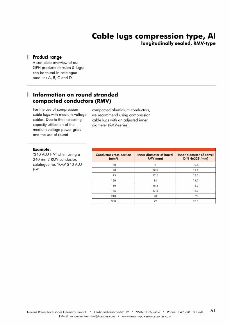
61Nexans Power Accessories Germany GmbH • Ferdinand-Porsche-Str. 12 • 95028 Hof/Saale • Phone: +49 9281 8306-0E-Mail: [email protected] • www.nexans-power-accessories.com
Information on round stranded compacted conductors (RMV)
Example: "240 ALU-F-V" when using a240 mm2 RMV conductor, catalogue no. "RMV 240 ALU-F-V"
For the use of compression cable lugs with medium-voltage cables. Due to the increasing capacity utilisation of the medium voltage power grids and the use of round
Conductor cross-section (mm²)
Inner diameter of barrelRMV (mm)
Inner diameter of barrelDIN 46329 (mm)
50 9 9.8
70 DIN 11.2
95 12.5 13.2
120 14 14.7
150 15.5 16.3
185 17.5 18.3
240 20 21
300 22 23.3
compacted aluminium conductors,we recommend using compression cable lugs with an adjusted inner diameter (RMV-series).
Product rangeA complete overview of ourGPH products (ferrules & lugs) can be found in catalogue modules A, B, C and D.
Cable lugs compression type, Allongitudinally sealed, RMV-type

62
15-0
5-20
14
M - SERIESMechanical connectors, type M
ApplicationOur mechanical connectors areassembled with multiple shear-off-head bolts and are therefore a reliable and economical way of connecting identical or different conductor cross-sections and conductor materials.
Design
M95-240 centric, with shear-off-head bolts and transverse grooving
b
D
L
d
Cat. no. Conductor cross-section Aluminium (mm²)
Conductor cross-sec-tion Copper (mm²)
Num-ber of bolts
Dimensions(mm)
Tool / outer
and inner hexagonrm(v) re sm rm(v) sm L d1 D b
M16-95 16-95 16-95 25-70 16-95 25-70 2 70 12.5 24 32 SW13 & SW6
M50-150 25-150 25-150 35-120 25-120 35-120 2 85 15.5 30 35 SW17 & SW6
M50-150/
16-95
1.Seite 25-150 25-150 35-120 25-120 35-1202 85
15.530
35 SW17 & SW6
2.Seite 16-95 10-95 25-70 10-70 25-70 12.5 35 SW13 & SW6
M70-240 (502))70-240 70-240 70-240 (502))70-240 70-240 4 120 221) 35 56 SW19 & SW6
M95-240 95-240 95-240 95-185 95-240 95-185 4 120 20 33 56 SW19 & SW6
M95-240/
16-95
1.Seite 95-240 95-240 95-185 95-240 95-1853 120
2033
56 SW19 & SW6
2.Seite 16-95 16-95 25-70 16-70 25-70 12.5 56 SW13 & SW6
M120-300 120-300 120-300 120-240 120-300 120-240 4 142 25 38 67 SW22 & SW6
M120-300/
16-95
1.Seite 120-300 120-300 120-240 120-300 120-2403 142
2538
67 SW22 & SW6
2.Seite 16-95 10-95 25-70 10-70 25-70 12.5 32 SW13 & SW6
M120-300/
95-240
1.Seite 120-300 120-300 120-240 120-300 120-2404 142
2538
67 SW22 & SW6
2.Seite 95-240 95-240 95-185 95-240 95-185 20 60 SW19 & SW6
M185-400 185-400 185-400 185-300 185-400 185-300 6 170 26 42 82 SW22 & SW6
M185-400/
95-240
1.Seite 185-400 185-400 185-300 185-400 185-3005 170
26 42
82 SW22 & SW6
2.Seite 95-240 95-240 95-185 95-240 95-185 20 56 SW19 & SW6
M300-500 300-500 300-500 300-400 300-500 300-400 6 200 34 52 94 SW24 & SW8
M400-630 400-630 400-630 400-500 400-630 400-500 6 200 34 52 94 SW24 & SW8
M400-630/
120-300
1.Seite 400-630 400-630 400-500 400-630 400-5005 200
34 52
94 SW24 & SW8
2.Seite 120-300 120-300 120-240 120-300 120-240 25 67 SW22 & SW6
M630-1000 630-1000 630-1000 / 630-1000 / 8 220 41 65 105 SW22 & SW8
M ...
M70-240
1) Dimension d2=26. 2) must be ordered separately
Advantages· Simple, quick installation: With common commercially available inner and outer hexagon tools or an approved impact wrench.
· Minimum storage costs: The cross-sectional area from 16 mm² to 1000 mm² is covered by just 4 types of connectors.
· Universal applicability: Can be used for copper and aluminium conductors according to EN 60228 classes 1 & 2. For use of our mechanical connectors with class 5 flexible copper conductors, please contact us.· Proven quality: Tested for class 2 conductors according to IEC 61238-1, in failure-free operation for more than 15 years.
MaterialConnector body: AluminiumlegierungBolts: brass, tin-plated, with inner and outer hexagonSurfaceConnector body: tin-plated

63Nexans Power Accessories Germany GmbH • Ferdinand-Porsche-Str. 12 • 95028 Hof/Saale • Phone: +49 9281 8306-0E-Mail: [email protected] • www.nexans-power-accessories.com
Specifications andstandardsThe mechanical connectorshave been tested according toIEC 61238-1 or VDE 0220 part100 respectively.
Ordering instructionsPlease indicate the part num-ber when ordering (see table). The centring rings or centring inserts are part of the scope of delivery.
Order example1 mechanical connector for95-240 mm². Order according to the table:1 M95-240 with part number G6402 50 16.
Centring of the conductorFor the centric position ofsmaller conductor cross-sections in the conductorchannel, we use centring ringsthat must be pressed all theway into the channel of theconnector before assembling
the corresponding conductor cross-section.The centring rings differin colour and are assigned tothe respective type of conductor.Appropriate assemblyinstructions describe which type
of conductor the centringrings are to be used for. Theconductor is centred usinga centring insert in the caseof the largest cross-sectionalarea.
Mechanical connector type Ordering part number
M16-95 G6402 50 31
M50-150
M50-150/16-95
G6402 50 15
G6402 50 37
M70-240 G6402 50 60
M95-240
M95-240/16-95
G6402 50 16
G6402 50 36
M120-300
M120-300/16-95
M120-300/95-240
G6402 50 33
G6402 50 38
G6402 50 40
M185-400
M185-400/95-240
G6402 50 27
G6402 50 35
M300-500 G6402 50 62
M400-630
M400-630/120-300
G6402 50 44
G6402 50 54
M630-1000 G6402 51 10
Cu
Al
Technical detailsThe bolt has an inner and outer hexagon. Both are related to the various shear-off-areas of the bolt and their different tor-que moments.
The torque moments follow the rule that large conductor cross sections need high torque moments and smaller cross sections need lower torque moments.
The installation instruction describes the use of both hexagons and of the various center rings and inserts, for the respective conductor types.
Product rangeA complete overview of ourGPH products (ferrules & lugs) can be found in catalogue modules A, B, C and D.
It is possible to connectdifferent conductor cross-
sections.
Can be supplied with all common types of
cable lugs.
It is possible to connectdifferent conductor
materials.
We use centring rings forthe centric position of small conductor cross-
sections.
Can be used for allconductor shapes.

64
15-0
5-20
14
D - SERIEMechanical connectors, type D
ApplicationWith the low-voltage mechanicalconnectors of the D-series,both identical and different conductor cross-sections can beimplemented in the area ofapplication, irrespective of theconductor material, shape and design. A total of seven connector sizes are available.
Design
1) Connector Body: Brass 2) Double shear-off-head bolt 3) without sector channel 4) Hexagon socket bolt, steel 5) Bolt, brass (tin plated)
Advantages· Simple, quick installation: With common commercially available inner and outer hexagon tools or an approved impact wrench.
· Minimum storage costs: The cross-sectional area from 1.5 mm² to 240 mm² is covered by just 3 types of connectors.
· Universal applicability: Can be used for copper and aluminium conductors according to EN 60228 classes 1 & 2. For use of our mechanical connectors with class 5 flexible copper conductors, please contact us.· Proven quality: Our D-series connectors are a consistent further development of the long-term proven and tested SV-series.
D25-185 SV-T-V-K
D1,5-16 SV-S-V-K
Material: Connector body: brass- (D1,5-16 SV) or high strength alumnium alloy
Bolts: brass- or high strength alumnium alloy tin-plated, with inner and outer hexagon Surface: D ...-V: tin-plated
Bolts: D ...: with hexagon socket bolts D ...-K: with shear-off-head bolts
Connector Body: D ...-S: with inspection hole at right angles to the barrelD ...-T: with oil stop
Cat. no AL acc. to VDE0295 table 5-9
(mm²)
CU acc. to VDE0295 table 5-9
(mm²)
Number of bolts
Dimensions (mm)
Torque moment
(Nm)
Tool / outer and inner hexagon
rm sm re se rm sm re L D d shear-off head bolt
hexagon socket bolt
D1,5-16 SV(-T/-S)-V-K 1),3) 10-16 10-16 1.5-16 1.5-16 2 30 12 6.1 4 SW8
D1,5-16 SV(-T/-S)-V 1),3) 1.5-16 1.5-16 2 30 12 6.1 4 SW34)
D1,5-35 SV(-T/-S)-V-K 3) 10-35 35 10-35 35 1.5-35 35 1.5-35 2 36 16 9.0 SW52)
D10-35 SV(-T/-S)-V(-K) 3) 10-35 35 10-35 35 10-35 35 10-35 2 36 16 9.0 10 SW10 SW5
D25-50 SV(-T/-S)-V(-K) 25-50 35-50 25-50 35-50 25-50 35-50 25-35 2 36 18 10.0 12 SW10 SW5
D4-50 SV(-T/-S)-V-K 10-50 35-50 10-50 35-50 4-50 35-50 4-35 2 36 18 10.0 SW52)
D16-95 SV(-T/-S)-V(-K) 16-95 35-95 16-95 35-95 16-95 35-95 16-35 2 55 25 14.0 22 SW10 SW6
D25-150 SV(-T/-S)-V-K 25-150 35-150 25-150 35-150 25-150 35-150 16-35 2 70 28 17.0 SW62) 5)
D35-150 SV(-T/-S)-V(-K) 35-150 35-150 50-150 50-150 35-150 35-150 35 2 70 28 17.0 30 SW135) SW65)
D25-185 SV(-T/-S)-V-K 25-185 35-185 25-185 35-185 25-185 35-185 25-35 4 80 32 19.0 SW62)
D70-185 SV(-T/-S)-V(-K) 70-185 70-185 70-185 70-185 70-185 70-185 4 80 32 19.0 30 SW13 SW6
D50-240 SV(-T/-S)-V-K 50-240 50-240 50-240 50-240 50-240 50-240 4 120 35 22.0 SW62)
D120-240 SV(-T/-S)-V(-K) 120-240 120-240 120-240 120-240 120-240 120-240 4 120 35 22.0 38 SW17 SW6
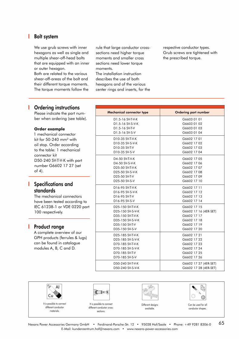
65Nexans Power Accessories Germany GmbH • Ferdinand-Porsche-Str. 12 • 95028 Hof/Saale • Phone: +49 9281 8306-0E-Mail: [email protected] • www.nexans-power-accessories.com
Ordering instructionsPlease indicate the part num-ber when ordering (see table).
Order example1 mechanical connectorkit for 50-240 mm² with oil stop. Order according to the table: 1 mechanical connector kitD50-240 SV-T-V-K with partnumber G6602 17 27 (set of 4).
Mechanical connector type Ordering part number
D1.5-16 SV-T-V-K D1.5-16 SV-S-V-K D1.5-16 SV-T-V D1.5-16 SV-S-V
G6603 01 01G6603 01 02G6603 01 03G6603 01 04
D10-35 SV-T-V-K D10-35 SV-S-V-K D10-35 SV-T-V D10-35 SV-S-V
G6602 17 01G6602 17 02G6602 17 03G6602 17 04
D4-50 SV-T-V-K D4-50 SV-S-V-K D25-50 SV-T-V-K D25-50 SV-S-V-K D25-50 SV-T-V D25-50 SV-S-V
G6602 17 05G6602 17 06G6602 17 07G6602 17 08G6602 17 09G6602 17 10
D16-95 SV-T-V-K D16-95 SV-S-V-K D16-95 SV-T-V D16-95 SV-S-V
G6602 17 11G6602 17 12G6602 17 13G6602 17 14
D25-150 SV-T-V-K D25-150 SV-S-V-K D35-150 SV-T-V-K D35-150 SV-S-V-K D35-150 SV-T-V D35-150 SV-S-V
G6602 17 15 G6602 17 16 (4ER-SET)
G6602 17 17G6602 17 18G6602 17 19G6602 17 20
D25-185 SV-T-V-K D25-185 SV-S-V-K D70-185 SV-T-V-K D70-185 SV-S-V-K D70-185 SV-T-V D70-185 SV-S-V
G6602 17 21G6602 17 22G6602 17 23G6602 17 24G6602 17 25G6602 17 26
D50-240 SV-T-V-K D50-240 SV-S-V-K
G6602 17 27 (4ER-SET) G6602 17 28 (4ER-SET)
It is possible to connectdifferent conductor cross-
sections.
Different designs available.
Cu
Al
It is possible to connectdifferent conductor
materials.
Can be used for allconductor shapes.
Bolt system
We use grub screws with innerhexagons as well as single andmultiple shear-off-head bolts that are equipped with an inner or outer hexagon. Both are related to the various shear-off-areas of the bolt andtheir different torque moments.The torque moments follow the
rule that large conductor cross-sections need higher torquemoments and smaller cross sections need lower torque moments. The installation instruction describes the use of both hexagons and of the various center rings and inserts, for the
respective conductor types.Grub screws are tightened withthe prescribed torque.
Specifications andstandardsThe mechanical connectorshave been tested according toIEC 61238-1 or VDE 0220 part100 respectively.
Product rangeA complete overview of ourGPH products (ferrules & lugs) can be found in catalogue modules A, B, C and D.

66
15-0
5-20
14
Specifications andstandardsHeat-shrinkable tubes meet therequirements of CENELEC HD631.2 S1. The dimensions of the mechanical connectors, thathave been tested according toIEC 61238-1 or VDE 0220 part100 respectively, correspond toDIN V 47640.
SVMS / SVMS-PHeat-shrinkable in-line joints including mechanical connectors
without/with parking position, suitable for installation undervoltage, design acc. to DIN V 47640
ApplicationSVMS / SVMS-P joints aredesigned for all 3 ½, 4 and 5core polymeric insulated cables(e.g. N(A)YY, N(A)YC(W)Y) withPVC or XLPE insulation as wellas for PVC or PE outer sheaths.The joints are designed foruse of mechanical connectorsaccommodating copper or
Design The joints consist of number 4up to 5 of inner and 1 outerheat-shrinkable tube. All tubingin the kit is thick-walled andco-extruded with adhesivequality. Tubes dimensions areaccording to DIN V 47640.
Technical characteristics For application SVMS-Pincluding a parking positionon conductors for mechanicalcontacts a connector withoutoil stop is mandatory. Tubelengths for inner joints are thandifferent to SVMS once.
U0 / U (Um ) 0.6/1 (1.2) kValuminum conductors. Joints
offer a sealed indoor oroutdoor application, fullysubmersible or directly buried.
l2
D2/
d 2D
1/d 1
l1

67Nexans Power Accessories Germany GmbH • Ferdinand-Porsche-Str. 12 • 95028 Hof/Saale • Phone: +49 9281 8306-0E-Mail: [email protected] • www.nexans-power-accessories.com
Kit contentsThe heat-shrinkable in-linejoints are composed withfollowing components:
Ordering instructionsSelect the order part number ofthe joint type according to thecable type and the conductorcross-section.
ExampleHeat-shrinkable in-line joint fora 4 core polymeric insulatedcable, nominal voltage 0.6/1 kV,conductor cross-section35-150 mm²Part number: 53186
• 4 (5) x inner joints• 1 x overall protection tube• 4 (5) x mechanical connectors with/without oil stop• installation instructions
Joint typeDimensions outer tubes Dimensions inner tubes Ordering
part numberl1 D1/d1 Qty. / KIT l2 D2/d2 Qty. / KIT
SVMS Gr. 1 4 x 4-16
SVMS Gr. 1B 5 x 4-16
SVMS Gr. 2 4 x 16*-35
SVMS Gr. 3 4 x 25-50
SVMS Gr. 4 4 x 35-95
SVMS Gr. 5 4 x 35-150
SVMS Gr. 6 4 x 95-150
SVMS Gr. 7 4 x 95*-240
360
360
370
440
630
780
780
950
43/12
43/12
55/16
70/21
85/25
110/26
110/26
130/36
1
1
1
1
1
1
1
1
100
100
100
130
160
210
210
260
15/4
15/4
22/6
22/6
33/8
33/8
43/12
43/12
4
5
4
4
4
4
4
4
53182
53619
53183
53184
53185
53186
53187
53188
* Only for PVC-insulated cables according to DIN VDE 0276 - 603
SVMS HEAT-SHRINKABLE IN-LINE JOINT incl. mechanical connectors with oil stop up to0.6/1 (1.2) kV without parking position for the connector on the conductors
SVMS-P HEAT-SHRINKABLE IN-LINE JOINT incl. mechanical connectors without oil stopup to 0.6/1 (1.2) kV with parking position for the connector on the conductors
Joint typeDimensions outer tubes Dimensions inner tubes Ordering
part numberl1 D1/d1 Qty. / KIT l2 D2/d2 Qty. / KIT
SVMS-P Gr. 1 4 x 4-16
SVMS-P Gr. 1B 5 x 4-16
SVMS-P Gr. 2 4 x 16*-35
SVMS-P Gr. 3 4 x 25-50
SVMS-P Gr. 4 4 x 35-95
SVMS-P Gr. 5 4 x 35-150
SVMS-P Gr. 6 4 x 95-150
SVMS-P Gr. 7 4 x 95*-240
420
420
430
500
710
890
890
1100
43/12
43/12
55/16
70/21
85/25
110/26
110/26
130/36
1
1
1
1
1
1
1
1
120
120
120
155
190
250
250
330
15/4
15/4
22/6
22/6
33/8
33/8
43/12
43/12
4
5
4
4
4
4
4
4
53189
57768
53190
53191
53192
53193
53194
53195
* Only for PVC-insulated cables according to DIN VDE 0276 - 603
For use with other cross section, please contact our
representative.
For use with other cables, please contact our
representative.

68
15-0
5-20
14
Rheycut II peeling toolwith stop ring, size 1
Article numbers: peeling tool 51494 / spare cutter 51495
The peeling tool is suitable forremoving the extruded outer semiconductive cable screen of me-dium voltage cables. Field of application: Diameter over core insulation between 10 mm upto 52 mm. Depending on the required length of the outer semi-con layer it is possible to use the tool with or without length control.By using the tool without the length
control the semi-con layer can beremoved up to a length of 25 mmmeasured from cut-off edge ofouter cable sheath.Cutting depth is around 0.75 mm.In the event of semi-conductivescreen thicker than this you canadjust the cutting depth of the blade up to a maximum of 1.2 mm.
2-in-1 cable sheath andcable insulation cutter, size 1 The tool is engineered for professi-
onal and safe stripping of theouter cable sheath of mediumvoltage cables having a minimumouter diameter of 15 mm up tomaximum diameter of 57 mm. The tool is also suitable for remo-ving polymeric insulation ofmedium voltage cables in the aforementioned range.
Article numbers: cable sheath 59117 / spare cutter 51488
It has been designed to providespiral cutting (longitudinal) as wellas circumferential cutting. Theblade is specially formed with aguiding system lifting the materialwhile cutting it to avoid any dama-ges to the layers underneath.Cutting depth is adjustable.
Chamfering tool, size 1
The chamfering tool is suitable forXLPE cable insulation for a range ofdiameter from 12 mm to 45 mm. This very simple to handle toolremoves sharp edges at the cut-offedge of cable insulation to avoidpossible damage to and to easeinstallation of slip-on accessories.
Article numbers: chamfering tool 43523 / spare cutter 44129
Due to its specially formed bladea radius is produced at the cut-offedge. This reduces enormously theforce required to install non-sizesensitive slip-on accessories.
Rheycut® InsulationStripping Tool
Tool for removing the core insulati-on of PVC or XLPE insulatedmedium voltage cables.Separate tools for voltage level of10 kV, 20 kV and 30 kV can be delivered. Therefore no adjustment
Article numbers: 40001 for 10 kV; 40002 for 20 kV; 40003 for 30 kVArticle numbers: spare cutter: 41083 for 10 kV; 41084 for 20 kV; 41085 for 30 kV
of voltage level or conductor crosssection is necessary. Dama-ging the cable conductor is impos-sible due to the fixed cutting depth.
Cable preparation tools for installationMV accessories

69
Cable preparation tools for installationMV accessories - for cables with conductor cross-sections > 500 mm²
Rheycut II peeling toolwith stop ring, size 2
Article numbers: peeling tool 55152 / spare cutter 51495
The peeling tool is suitable forremoving the extruded outer semiconductive cable screen of me-dium voltage cables. Field of application: Diameter over core insulation between 15 mm upto 60 mm. Depending on the required length of the outer semi-con layer it is possible to use the tool with or without length control.
By using the tool without the lengthcontrol the semi-con layer can beremoved up to a length of 25 mmmeasured from cut-off edge ofouter cable sheath.In the event of semi-conductivescreen thicker than this you canadjust the cutting depth of the bla-de up to a maximum of 1.2 mm.
2-in-1 cable sheath andcable insulation cutter, size 2 The tool is engineered for professi-
onal and safe stripping of theouter cable sheath of mediumvoltage cables having a minimumouter diameter of 20 mm up tomaximum diameter of 70 mm.The tool is also suitable for remo-ving polymeric insulation ofmedium voltage cables in the afo rementioned range.It has been designed to provide
Article numbers: cable sheath 59118 / spare cutter 55541
spiral cutting (longitudinal) as wellas circumferential cutting. Theblade is specially formed with aguiding system lifting the materialwhile cutting it to avoid any dama-ges to the layers underneath.Cutting depth is adjustable.
Chamfering tool, size 2
The chamfering tool is suitable forXLPE cable insulation for a range ofdiameter from 15 mm to 60 mm.This very simple to handle toolremoves sharp edges at the cut-offedge of cable insulation to avoidpossible damage to and to ease
Article numbers: chamfering tool 55154 / spare cutter 44129
installation of slip-on accessories.Due to its specially formed bladea radius is produced at the cut-offedge. This reduces enormously theforce required to install non-sizesensitive slip-on accessories.

70
15-0
5-20
14
Tool case complete, size 1 (for cross-sections up to 500 mm2)
Tool case complete, size 2 (for cross-sections > 500 mm2)
Ordering part number: Tool case complete 51426
Ordering part number: Tool case complete 55155
(Figure: Tool case complete, size 1, for cross-sections up to 500 mm2)
Scope of delivery: Rigid case, two-in-one cable sheath and cable insulation cutter, chamfering tool,devices (stop rings, silicone grease and allen key for tooling adjustments)
Catalogue selectionHere you can find an overview ofthe available catalogues for ourGPH and Nexans products. You canorder these catalogues by phone ordownload the data from our webpage.
www.nexans-power-accessories.com
• Heat-shrinkable straight joints and accessories up to 0.6/1 (1.2) kV• Heat-shrink technology up to 18/30 (36) kV)• Cold-shrinkable joints• Medium voltage equipment bushings• Cold-shrinkable terminations • Heat-shrinkable terminations• High Voltage Accessories up to 170 kV• Separable connectors for interface A• Separable connectors for interface B• Separable connectors for interface C• Separable connectors for interface D• Separable connectors for interface E• Separable connectors for interface F
Ferrules & lugs• Catalogue A – clamps• Catalogue B – compression joints• Catalogue C – compression cable lugs• Catalogue D – mechanical connectors, mechanical cable lugs and tools

71Nexans Power Accessories Germany GmbH • Ferdinand-Porsche-Str. 12 • 95028 Hof/Saale • Phone: +49 9281 8306-0E-Mail: [email protected] • www.nexans-power-accessories.com
15-0
5-20
14
Kit contents• Rods, loose, length 100 mm• Hexagon socket key SW5• Nylon bag• Instruction manual
Material• Operating parts and rods manufactured of high- strength quality steel• Engine body made of aluminium with anodised surface
DMV65Torque amplifier
ApplicationThe torque amplifier DMV65 is appropriate for a gentle removal of shear-off-head bolts of mechanical connectors using standard cordless screwdrivers. The tool enables an optimum clamping force using mechanical GPH connectors with conductor cross-sections up to 630 mm².The DMV65 ensures outstanding installation quality for mechani-cal connectors and cable lugs up to Ø 52 mm.
Technical characteristics• Bit-entry• ½" Square for mounting of the socket wrench• Rod length 80,5 mm• Transmission ratio 1:24• Max. engine torque 65 Nm• Min. driving torque 5 Nm
Important notice• The torque amplifier is not approved for live working installation.• The tool does not have to be used for installation with impact wrenches.• Consider the installation instruction of the respective mechanical connector or cable lug.
Ordering instructions
Cat.-No. max. engine torque (Nm)
Package Dimensions (mm)
Weight (g)
DREHMOMENTVERSTÄRKER DMV65 65 Nylon bag 199 x 89 x 63 ca. 941
Design1. Rods, assembled, length 80,5 mm2. Rod socket3. Inner tapped hole for Ø < 40 mm4. Outer tapped hole for Ø < 53 mm5. ½" Square with ball coupling6. Release hole7. Gearbox8. Bit-entry9. Hexagon socket key SW5
1
1
2
5
6
789
3
4

15-0
5-20
14
72
CABLE DATA SHEET / INQUIRY FORM
Nexans Power Accessories Germany GmbH
Ferdinand-Porsche-Straße 12D-95028 Hof/Saale
Phone: +49(0)9281 / 8306 - 0Fax: +49(0)9281 / 8306 - 480E-Mail: [email protected]
Company:Customer ID:
Address: Phone:Fax: E-Mail:
Cable data:
Cable type: Single core Single core flexible rubber insulated cableThree core Three core flexible rubber insulated cableOther Standard
Conductor material: Aluminium cross section mm²Copper
Conductor shape:stranded conductor RM(V)solid conductor REflexible sector conductor SMsolid sector conductor SEflexible conductor RF Other
System voltage: Type of cable:3.6/6 (7.2) kV6/10 (12) kV6.35/11 (12) kV8.7/15 (17.5) kV12/20 (24) kV12.7/22 (24) kV18/30 (36) kV19/33 (36) kV 20.8/36 (42) kVOther: kV1. Ø Conductor2. Ø Core insulation XLPE PVC EPR 3. Ø Semi-conductive screen4. Semi-conductive layer bonded graphite coated easy strip
5. Metal screen Al Cu Wire screen Tape screen Cross section
6. Armour type Yes No Armour Max. Current A 7. Outer sheath diameter:
mmmmmm
mm
1 2 3 754 6
1 2 3 754 5 6


Nexans Power Accessories Germany GmbH • Ferdinand-Porsche-Str. 12 • 95028 Hof/Saale
Phone: +49 9281 8306-0 • E-Mail: [email protected] • www.nexans-power-accessories.com