Compact and Wideband Parallel-Strip 180° Hybrid Coupler with ...
11
Hindawi Publishing Corporation International Journal of Microwave Science and Technology Volume 2013, Article ID 567342, 10 pages http://dx.doi.org/10.1155/2013/567342 Research Article Compact and Wideband Parallel-Strip 180 ∘ Hybrid Coupler with Arbitrary Power Division Ratios Leung Chiu and Quan Xue Department of Electronic Engineering, City University of Hong Kong, Hong Kong Correspondence should be addressed to Leung Chiu; [email protected] Received 13 September 2013; Revised 15 November 2013; Accepted 2 December 2013 Academic Editor: Paolo Colantonio Copyright © 2013 L. Chiu and Q. Xue. is is an open access article distributed under the Creative Commons Attribution License, which permits unrestricted use, distribution, and reproduction in any medium, provided the original work is properly cited. is paper presents a class of wideband 180 ∘ hybrid (rat race) couplers implemented by parallel-strip line. By replacing the 270 ∘ arm of a conventional 180 ∘ hybrid coupler by a 90 ∘ arm with phase inverter, the bandwidth of the coupler is greatly enhanced and the total circuit size is reduced by almost half. Simple design formulas relating the characteristic impedance of the arms and power division ration are derived. To demonstrate the concept, four couplers with different power division ratios of 1, 2, 4, and 8 were designed, fabricated, and tested. -parameters of the coupler are simulated and measured with good agreement. All working prototypes operate more than 112% impedance bandwidth with more than 25 dB port-to-port isolation and less than 5 ∘ absolute phase imbalance. e proposed 180 ∘ hybrid couplers can be employed as a wideband in-phase/differential power divider/combiner, which are essential for many RF and microwave subsystem designs. 1. Introduction Nowadays the demands for compactness, light weight, and broadband have a great impact on design issues of a high performance RF and microwave front-ends at both com- ponent and system levels. Power dividers and combiners play critical roles in RF and microwave circuit designs as they are the fundamental and indispensable components in the wireless communications systems. e Wilkinson power divider, 90 ∘ hybrid coupler, and 180 ∘ hybrid coupler have unique features in both dividing and combining RF signals with port-to-port isolation in 0 ∘ , 90 ∘ , and 180 ∘ phase difference, respectively [1]. For applications such as push- pull amplifiers, balanced mixers, frequency multipliers, and antenna arrays, the 180 ∘ hybrid coupler is preferred. It is because not only the load impedance has a small impact on the isolation and input/output impedance matching of the 180 ∘ hybrid coupler, but also its operation bandwidth is wider than that of the 90 ∘ hybrid coupler [2]. However, circuit area of the 180 ∘ hybrid coupler is larger compared with both the Wilkinson power divider and the 90 ∘ hybrid coupler. In addition, demands from many widebands sparked the exploration of bandwidth enhancement techniques of various RF and microwave components, and the 180 ∘ hybrid coupler is no exception. Parallel-strip line [3, 4] belongs to the family of balanced transmission lines. It is a simple structure of a piece of dielec- tric substrate sandwiched by two strip conductors. Signals flowing on the upper and lower strip conductors are always equal in magnitude but 180 ∘ out of phase. is nature was applied to realize a 180 ∘ Wilkinson power divider/combiner for push-pull amplifier with wideband second-harmonic suppression [3]. In addition, the symmetry of the parallel- strip line implies that the “ground” and “signal” lines can be swapped freely in the circuit design. e parallel-strip phase reversal swap can easily be realized by “intercrossing” the upper and lower strip conductors by a pair of metal vias. e phase reversal swap, which is a simple passive microwave component, forms a compact realization of 180 ∘ phase shiſt which was employed to realize a power divider/combiner concept with enhanced isolation bandwidth [4]. A parallel-strip 180 ∘ hybrid coupler was proposed in [5] with a performance similar to the conventional design. In this letter, a compact wideband 180 ∘ hybrid coupler, implemented by parallel-strip line, is achieved by replacing the 270 ∘ arm of the conventional 180 ∘ hybrid coupler with a section of 90 ∘
-
Upload
truongnguyet -
Category
Documents
-
view
230 -
download
0
Transcript of Compact and Wideband Parallel-Strip 180° Hybrid Coupler with ...

Hindawi Publishing CorporationInternational Journal of Microwave Science and TechnologyVolume 2013 Article ID 567342 10 pageshttpdxdoiorg1011552013567342
Research ArticleCompact and Wideband Parallel-Strip 180∘ Hybrid Coupler withArbitrary Power Division Ratios
Leung Chiu and Quan Xue
Department of Electronic Engineering City University of Hong Kong Hong Kong
Correspondence should be addressed to Leung Chiu eechiuleungyahoocomhk
Received 13 September 2013 Revised 15 November 2013 Accepted 2 December 2013
Academic Editor Paolo Colantonio
Copyright copy 2013 L Chiu and Q XueThis is an open access article distributed under the Creative Commons Attribution Licensewhich permits unrestricted use distribution and reproduction in any medium provided the original work is properly cited
This paper presents a class of wideband 180∘ hybrid (rat race) couplers implemented by parallel-strip line By replacing the 270∘arm of a conventional 180∘ hybrid coupler by a 90∘ arm with phase inverter the bandwidth of the coupler is greatly enhancedand the total circuit size is reduced by almost half Simple design formulas relating the characteristic impedance of the arms andpower division ration are derived To demonstrate the concept four couplers with different power division ratios of 1 2 4 and 8were designed fabricated and tested 119878-parameters of the coupler are simulated and measured with good agreement All workingprototypes operate more than 112 impedance bandwidth with more than 25 dB port-to-port isolation and less than 5∘ absolutephase imbalanceThe proposed 180∘ hybrid couplers can be employed as a wideband in-phasedifferential power dividercombinerwhich are essential for many RF and microwave subsystem designs
1 Introduction
Nowadays the demands for compactness light weight andbroadband have a great impact on design issues of a highperformance RF and microwave front-ends at both com-ponent and system levels Power dividers and combinersplay critical roles in RF and microwave circuit designs asthey are the fundamental and indispensable componentsin the wireless communications systems The Wilkinsonpower divider 90∘ hybrid coupler and 180∘ hybrid couplerhave unique features in both dividing and combining RFsignals with port-to-port isolation in 0∘ 90∘ and 180∘ phasedifference respectively [1] For applications such as push-pull amplifiers balanced mixers frequency multipliers andantenna arrays the 180∘ hybrid coupler is preferred It isbecause not only the load impedance has a small impacton the isolation and inputoutput impedance matching ofthe 180∘ hybrid coupler but also its operation bandwidthis wider than that of the 90∘ hybrid coupler [2] Howevercircuit area of the 180∘ hybrid coupler is larger compared withboth theWilkinson power divider and the 90∘ hybrid couplerIn addition demands from many widebands sparked theexploration of bandwidth enhancement techniques of various
RF and microwave components and the 180∘ hybrid coupleris no exception
Parallel-strip line [3 4] belongs to the family of balancedtransmission lines It is a simple structure of a piece of dielec-tric substrate sandwiched by two strip conductors Signalsflowing on the upper and lower strip conductors are alwaysequal in magnitude but 180∘ out of phase This nature wasapplied to realize a 180∘ Wilkinson power dividercombinerfor push-pull amplifier with wideband second-harmonicsuppression [3] In addition the symmetry of the parallel-strip line implies that the ldquogroundrdquo and ldquosignalrdquo lines can beswapped freely in the circuit design The parallel-strip phasereversal swap can easily be realized by ldquointercrossingrdquo theupper and lower strip conductors by a pair of metal viasThe phase reversal swap which is a simple passive microwavecomponent forms a compact realization of 180∘ phase shiftwhich was employed to realize a power dividercombinerconcept with enhanced isolation bandwidth [4]
A parallel-strip 180∘ hybrid coupler was proposed in [5]with a performance similar to the conventional design In thisletter a compact wideband 180∘ hybrid coupler implementedby parallel-strip line is achieved by replacing the 270∘ armof the conventional 180∘ hybrid coupler with a section of 90∘
2 International Journal of Microwave Science and Technology
Phase inverter
Port 1
Port 3
Port 2
Port 4
Line of symmetry
ZA
ZA
ZB ZB
Figure 1 Schematic diagram of a 180∘ hybrid coupler with phaseinverter
parallel-strip line and the phase reversal swap In additionto size reduction the couplerrsquos bandwidth is dramaticallyenhanced A wideband parallel-strip 90∘ hybrid coupler wasproposed in [6] However the size of the proposed 90∘ hybridcoupler is almost double that of the 180∘ hybrid couplerreported in [4] Similar to [4] a swap or phase inverteris employed to enhance bandwidth Unlike the 180∘ hybridcoupler large magnitude imbalance is obtained over theworking frequency band In this work we not only designa 180∘ hybrid coupler with equal power division but alsoextend the concept to that with arbitrary power divisionDesign formula is derived based on even- and odd-modeanalysis Four couplers with different power divisions aredesigned fabricated and measured
2 Analysis
A schematic diagram of a 180∘ hybrid coupler with aphase inverter is shown in Figure 1 It consists of 4 armswith quarter-wavelength long By changing the characteristicimpedance of each arm different power divisions can beachieved Equations relating characteristic impedances andpower division ratio are derived in this section
By applying odd- and even-mode analysis the coupler isdivided by half in which the line of symmetry is terminatedeither by open circuit or by short circuit Figure 2 shows
the odd- and even-mode half structures of the coupler Thecharacteristic impedances of the series transmission line andthe two shunt (open- and short-circuit) stubs are 119885
119860and
119885119861 and their electrical lengths are 90∘ and 45∘ at the center
frequency respectively The two half structures are exactlythe same except that the port assignments are reversedTherefore the odd- and even-mode 119878-parameters can berelated by
11987811119890= 11987822119900
11987822119890= 11987811119900
11987812119890= 11987821119890= 11987812119900= 11987821119900
(1)
where (119878119890) = (
1198781111989011987812119890
1198782111989011987822119890
) and (119878119900) = (
1198781111990011987812119900
1198782111990011987822119900
) are the even- andodd-mode 119878-matrixes respectively To simplify the analysiswe only consider the parameters at center frequency Theoverall ABCD-matrix of the even-mode half structure is theproduct of the ABCD-matrix representing the shunt shortopen-circuit stub series transmission line and shunt short-circuit stub given by
(
1 0
119895
tan 45∘
119885119861
1
)(
cos 90∘ 119895119885119860sin 90∘
119895
1
119885119860
sin 90∘ cos 90∘ )
times(
1 0
1
119895119885119861tan 45∘
1
)
(2)
and the overall matrix is expressed by
(
119885119860
119885119861
119895119885119860
119895 (
1
119885119860
+
119885119860
119885119861
2
) minus
119885119860
119885119861
) (3)
The even-mode 119878-matrix can be conversed from the ABCD-parameter given by
(119878119890) = (
1198851198601198850minus 1198850119885119860minus 1198850119885119860119885119861
2
minus 119895 (2119885119860119885119861)
1198851198601198850+ 1198850119885119860+ 1198850119885119860119885119861
2
2
1198851198601198850+ 1198850119885119860+ 1198850119885119860119885119861
2
2
1198851198601198850+ 1198850119885119860+ 1198850119885119860119885119861
2
1198851198601198850minus 1198850119885119860minus 1198850119885119860119885119861
2
+ 119895 (2119885119860119885119861)
1198851198601198850+ 1198850119885119860+ 1198850119885119860119885119861
2
) (4)
Using (1) the odd-mode 119878-matrix can be expressed by
(119878119900) = (
1198851198601198850minus 1198850119885119860minus 1198850119885119860119885119861
2
+ 119895 (2119885119860119885119861)
1198851198601198850+ 1198850119885119860+ 1198850119885119860119885119861
2
2
1198851198601198850+ 1198850119885119860+ 1198850119885119860119885119861
2
2
1198851198601198850+ 1198850119885119860+ 1198850119885119860119885119861
2
1198851198601198850minus 1198850119885119860minus 1198850119885119860119885119861
2
minus 119895 (2119885119860119885119861)
1198851198601198850+ 1198850119885119860+ 1198850119885119860119885119861
2
) (5)
International Journal of Microwave Science and Technology 3
Port 1 Port 2ZA 90∘
ZB 45∘ ZB 45∘
(a)
Port 1 Port 2ZA 90∘
ZB 45∘ ZB 45∘
(b)
Figure 2 (a) Even-mode of the 180∘ hybrid coupler with phase inverter (b) Odd-mode of the 180∘ hybrid coupler with phase inverter
Once both even- and odd-mode 119878-matrixes are determinedthe 119878-parameters 119878
11 11987821 11987831 and 119878
41 of the entire coupler
can be determined by the following well-known formulas
11987811=
11987811119890+ 11987811119900
2
=
1198851198601198850minus 1198850119885119860minus 1198850119885119860119885119861
2
1198851198601198850+ 1198850119885119860+ 1198850119885119860119885119861
2
11987821=
11987811119890minus 11987811119900
2
=
minus119895 (2119885119860119885119861)
1198851198601198850+ 1198850119885119860+ 1198850119885119860119885119861
2
11987831=
11987821119890minus 11987821119900
2
= 0
11987841=
11987821119890+ 11987821119900
2
=
2
1198851198601198850+ 1198850119885119860+ 1198850119885119860119885119861
2
(6)
11987831
is always zero resulting in port 3 always being isolatedfromport 1 If 119878
11= 0 is assumed then it indicates that perfect
impedance matching is achieved at the center frequency Astraightforward calculation derives
119885119860
1198850
=
1198850
119885119860
+
1198850119885119860
119885119861
2
(7)
Hence the expressions of 11987821and 11987841can be reduced to
11987821= minus119895
1198850
119885119861
11987841=
1198850
119885119860
(8)
The power division ratio is defined as 119896 = |1198782111987841|
2 and theexpression relating 119896 119885
119860 and 119885
119861is obtained as follows
119885119860=radic119896119885119861 (9)
By solving (7) and (9) the design equations for 119885119860and 119885
119861as
function of 119896 are given by
119885119860=radic1 + 119896119885
0 119885
119861= radic1 +
1
119896
1198850
(10)
3 Bandwidth Consideration
The 180∘ hybrid coupler with a phase inverter has widerbandwidth than that without phase inverter The frequencyresponse of the input impedance or the input reflectioncoefficient at port 1 should be considered By considering port1 as the input port the signal will be divided into two pathsand will be transmitted to port 2 and port 4 The ports 2and 4 should be considered as 119885
0resistors to ground in this
case With an assumption of ideal phase inverter the port 3is virtually grounded because the phase inverter introducesan additional 180∘ phase difference at port 3 Therefore thehybrid coupler becomes a single-port network as shown inFigure 3 According to the design equation (10) the fourtransmission line have 90∘ electrical length at the centrefrequency 119891
0 Electrical length input impedance and input
reflection coefficient are the functions of frequency 119891 Theinput impedance at port 1 119885in is given by
1
119885in= [119885119860
(11198850+ 1119895119885
119861tan 120579)minus1 + 119895119885
119860tan 120579
119885119860+ 119895(1119885
0+ 1119895119885
119861tan 120579)minus1 tan 120579
]
minus1
+ [119885119861
(11198850+ 1119895119885
119860tan 120579)minus1 + 119895119885
119861tan 120579
119885119861+ 119895(1119885
0+ 1119895119885
119860tan 120579)minus1 tan 120579
]
minus1
(11)
where 120579 = (1198911198910)90
∘ To simplify the analysis 180∘ hybridcoupler with equal power division 119896 = 1 is considered Using(10) the two characteristic impedances are119885
119860= 119885119861= radic2119885
0
and the input impedance becomes
119885in =1198850
radic2
radic2 + 119895 tan 1205791 + 119895 (1radic2) (tan 120579 minus cot 120579)
(12)
We consider the magnitude of the input reflection coefficientgiven by
Γin =119885in minus 1198850119885in + 1198850
=
119895 cot 1205792radic2 + 119895 (2 tan 120579 minus cot 120579)
(13)
The impedance bandwidth is defined as the frequency rangewith reflection coefficient less than minus10 dB hence we have
1003816100381610038161003816Γin1003816100381610038161003816=
1
2 tan2120579 + 1le minus10 dB (14)
4 International Journal of Microwave Science and Technology
ZA
ZA
(Z0)
(Z0)
Zin
ZB
ZB
Port 1
Port 2
Virtualground
Phaseinverter
Port 4
Port 3
Figure 3 Circuit diagram of the 180∘ hybrid coupler with port 1 excitation only
Bandwidth
SimulationEquation (14)
Normalized frequency
Inpu
t refl
ectio
n co
effici
ent
032
(minus10dB)
0
02
04
06
08
1
12 14 16 18 21080604020
Figure 4 Frequency responses of the reflection coefficients from Agilentrsquos ADS and (14)
Equation (14) represents the frequency response of the inputreflection coefficient or 119878
119894119894 where 119894 = 1 2 3 or 4 We also
built a 180∘ hybrid coupler with equal power division usingmicrowave circuit simulator Agilentrsquos ADS Equation (14) isverified by comparing the simulation as shown in Figure 4The required frequency range is determined as
1
90∘
(180
∘
minus tanminus1radicradic10 minus 1
2
)
le
119891
1198910
le
1
90∘
(180
∘
+ tanminus1radicradic10 minus 1
2
)
(15)
For the 180∘ hybrid coupler with phase inverter the theoreti-cal percentage bandwidth with reflection coefficient less thanminus10 dB is given by (290∘)tanminus1radic(radic10 minus 1)2 sim102
4 Parallel-Strip Phase Reversal Swap
Thephase inverter is achieved by interchanging the two signallines in the balance transmission line so that the signal is saidto be ldquoreversedrdquo therefore it provides 180∘ phase shiftwithoutrequiring a delay line which is often used in microstripimplementation Phase inverter is possible in coplanar strip[7] and coplanar waveguide [8] implementations howeverstubs are required for the phase reversal section and tran-sitions between different transmission lines (for the port
International Journal of Microwave Science and Technology 5
ViaStrip lines
Figure 5 3D view of the parallel-strip phase reversal swap (conductors only)
Port 1 Port 2
CC
CC
CSCSLV
+
minus
+
minus
RV
(a)
0 1 2 3 4Frequency (GHz)
Mag
nitu
de (d
B)
Lumped S11 Lumped S21EM S11 EM S21
minus50
minus40
minus30
minus20
minus10
0
10
(b)
Phas
e diff
eren
ce (d
eg)
Frequency (GHz)
200
195
190
185
180
175
170
165
1600 1 2 3 4
(c)
Figure 6 (a) Lumped-circuit model of the parallel-strip phase reversal swap (b) Comparison of simulated 119878-parameters between EMsimulation and lumped-circuit model (c) Phase difference of the transmission lines with phase inverter
Table 1 Required values of 119885119860
and 119885119861
for different power divisionratios
119896 119885119860
119885119861
1 7071Ω 7071Ω
2 8660Ω 6124Ω
4 1118Ω 5590Ω
8 1414Ω 5303Ω
and the phase reversal swap) complicate the entire circuitdesign Fortunately a phase inverter can be realized easily
by the parallel-strip line Figure 5 shows the 3D view of theparallel-strip phase inverter The upper and lower strip linesare interconnected by two vertical metallic vias Within thewhole simulation band (0ndash4GHz) less than 05 dB additionalinsertion loss is introduced and 180∘ phase shift is providedwith less than 2∘ phase error caused by the inclusion of thevias
The lump-circuit model of the parallel-strip phase rever-sal swap is illustrated in Figure 6(a)The parasitic capacitance(119862119878) is used to model the edge couplings between strips
residing on different layers The parasitic capacitance (119862119862)
is used to model the total effect due to edge couplings
6 International Journal of Microwave Science and Technology
Port 1
Port 3
Port 2
Port 4Wa
Wa
Wb
Wb
la
lb
lb
la
W W
WW
(a)
s
d
(b)
Figure 7 (a) Layouts of the coupler at upper and lower layers (b) Closed view of the layouts of the phase inverter at upper and lower layers
Port 1
Port 4 Port 3
Port 2
(a)
Port 2
Port 3 Port 4
Port 1Port 2
PorP t 3 Port 4
Port 1
(b)
Figure 8 (a) Top view of the fabricated 180∘ hybrid coupler with 119896 = 4 (b) Top view of the fabricated 180∘ hybrid coupler with 119896 = 4 Thecore coupler is inside the red circle and the transition betweenmicrostrip line and parallel-strip line is outside the red circles for measurementpurpose
between strips on the same layers and coupling between themetal viasThe parasitic inductance (119871
119881) and resistance (119877
119881)
are introduced by the vertical conductors in via holes andsoldering The parasitic components can be extracted fromelectromagnetic simulations to complete the lump-circuitmodel
Commercial electromagnetic simulator Ansoft HFSSwas employed to determine the optimal dimensions of
the phase reversal swap The substrate has a dielectricconstant of 265 and thickness of 15mm The gap widthson the top and bottom conductors are 02mm the linewidth is 34mm and the diameter of metallic vias is11mm with 7071Ω terminating ports Deembedding of theparameters was performed by utilizing the microwave circuitsimulator Agilentrsquos ADS Values of parasitic elements are119871119881= 2181 nH 119862
119878= 02939 pF 119862
119862= 03878 pF and
International Journal of Microwave Science and Technology 7S
-par
amet
ers (
dB)
minus50
minus40
minus30
minus20
minus10
0
0 1 2 3 4 5 6
Frequency (GHz)
S11MeaSim S11 Sim S21 Sim S31 Sim S41
S31Mea S41MeaS21Mea
(a)
0
90
180
270
0 1 2 3 4 5 6Frequency (GHz)
Phas
e diff
eren
ce (d
eg)
minus90
Sim in-phase Sim out-of-phaseMea in-phase Mea out-of-phase
(b)
Figure 9 Simulated and measured 119878-parameters of the coupler with equal power division (a) Frequency responses of magnitude (b)Frequency responses of phase differences of the couplerrsquos outputs
S-pa
ram
eter
s (dB
)
minus40
minus30
minus20
minus10
0
0 1 2 3 4 5 6
Frequency (GHz)
S11MeaSim S11 Sim S21 Sim S31 Sim S41
S31Mea S41MeaS21Mea
(a)
0
90
180
270
0 1 2 3 4 5 6Frequency (GHz)
Phas
e diff
eren
ces (
deg)
minus90
Sim in-phase Sim out-of-phaseMea in-phase Mea out-of-phase
(b)
Figure 10 Simulated and measured 119878-parameters of the coupler with 119896 = 2 (a) Frequency responses of magnitude (b) Frequency responsesof phase differences of the couplerrsquos outputs
119877119881= 02624Ω With these parameters the magnitude of
the 119878-parameters of the phase inverter versus frequency isshown in Figure 6(b) The phase difference of the sectionof parallel-strip lines with and without phase inverter isshown in Figure 6(c) It is obvious that the lumped-circuitmodel provides accurate performance prediction of the phasereversal swap
5 Measured Results
Four 180∘ hybrid couplers with four different power divisionratios 119896 and the same centre frequency of 2GHz weredesigned to verify the concept All couplers were prototypedon a printed circuit board with a dielectric constant of 265and substrate thickness of 15mm Figure 7 shows the layout
8 International Journal of Microwave Science and Technology
S-p
aram
eter
s (dB
)
minus40
minus30
minus20
minus10
0
0 1 2 3 4 5 6
Frequency (GHz)
S11MeaSim S11 Sim S21 Sim S31 Sim S41
S31Mea S41MeaS21Mea
(a)
0
90
180
270
0 1 2 3 4 5 6Frequency (GHz)
Phas
e diff
eren
ces (
deg)
minus90
Sim in-phase Sim out-of-phaseMea in-phase Mea out-of-phase
(b)
Figure 11 Simulated and measured 119878-parameters of the coupler with 119896 = 4 (a) Frequency responses of magnitude (b) Frequency responsesof phase differences of the couplerrsquos outputs
Table 2 Physical dimensions of the couplers with different power division ratios
119896 119908119886
119897119886
119908119887
119897119887
119908 119904 119889
1 34mm 249mm 34mm 249mm 53mm 02mm 11mm2 25mm 251mm 41mm 247mm 53mm 02mm 11mm4 17mm 255mm 46mm 249mm 53mm 02mm 11mm8 11mm 259mm 49mm 245mm 53mm 02mm 11mm
of the coupler with all physical dimensions width of parallel-strip port 119908 widths of two arms in the coupler 119908
119886and 119908
119887
lengths of the two arms 119897119886and 119897119887 gap width of the phase
inverter 119904 and via diameter of the phase inverter 119889 Doublelayers are required for any parallel-strip circuits The upperand the lower layouts are the same with the exception of thephase inverter part
The required values of characteristic impedances 119885119860and
119885119861with different values of 119896 are determined as shown in
Table 1 where all the port impedances are 50Ω The dimen-sions of all layouts were optimized by an electromagneticsimulator Ansoft HFSS to take into account the effects of T-junction and phase inverter discontinuities Table 2 shows theoptimized physical dimensions of the four couplers
The four couplers were fabricated by the standard printedcircuit fabrication process The photograph of the fabri-cated coupler with power division ratio of 119896 = 4 isshown in Figure 8 The three remaining fabricated couplersare similar to that shown in Figure 8 The circular corepart is inside the red circle where four parallel-strip lineto microstrip line transitions are outside the red circleand they are required for measurement The 119878-parameters
were measured using 4-port network analyzer with portimpedance of 50Ω Figures 9 10 11 and 12 show both simu-lated and measured performances of the four couplersTheseperformances include frequency responses of magnitudes ofthe 119878-parameters of the four couplers and frequency responseof the phase differences of the couplersrsquo outputs All fabricatedcouplers have similar core area of around 800mm2 Goodagreements of the linear magnitudes of all 119878-parametersbetween the simulation andmeasurement are achieved Sincethe magnitude of 119878
41is at the order of minus30 dB (order of
the linear magnitude is at 0001) small error in the linearmagnitude introduces large error in that of the logarithmicmagnitude
All couplers are designed at the center frequency of2GHz The proposed coupler works well at around centerfrequency The proposed coupler does not work at DC andlower frequency range since the swap introduces short circuitto all the ports The proposed coupler also does not workat around second-harmonic frequency range since the swapintroduces 180∘ phase shift Signals are cancelled at thethought and coupler ports Table 3 summarizes the measuredperformances of the three couplersThemeasured impedance
International Journal of Microwave Science and Technology 9
S-p
aram
eter
s (dB
)
minus40
minus30
minus20
minus10
0
0 1 2 3 4 5 6
Frequency (GHz)
S11MeaSim S11 Sim S21 Sim S31 Sim S41
S31Mea S41MeaS21Mea
(a)
0
90
180
270
0 1 2 3 4 5 6Frequency (GHz)
Phas
e diff
eren
ces (
deg)
minus90
Sim in-phase Sim out-of-phaseMea in-phase Mea out-of-phase
(b)
Figure 12 Simulated and measured 119878-parameters of the coupler with 119896 = 8 (a) Frequency responses of magnitude (b) Frequency responsesof phase differences of the couplerrsquos outputs
Table 3 Summarized performance of the four couplers
119896 Impedance bandwidth Average 119896 Port-to-port isolation Phase error1 120 102 gt29 dB lt5∘
2 112 185 gt27 dB lt5∘
4 119 289 gt25 dB lt7∘
8 129 755 gt28 dB lt6∘
bandwidths of all four couplers are larger than the theoreticalbandwidth 102 shown in Section 3 because of losses ofcircuit including transmission line T-junction and phaseinverter
6 Conclusion
A class of wideband and compact 180∘ parallel-strip hybridcoupler is presented Unlike microstrip line or coplanarwaveguide the parallel-strip line is a balanced transmissionline that consists of two metal strips at the top and bottomof the printed circuit board The parallel-strip circuit fullyunitizes the double layers of the printed circuit board toachieve higher performance than that of microstrip circuitwhere microstrip circuit is totally grounded at the bottomlayer Parallel-strip phase reversal swap is unique whereswap is not realized by either microstrip line or copla-nar waveguide By employing the frequency-independentparallel-strip phase reversal swap in conjunction with the90∘ section to replace the 270∘ section of the 180∘ hybridcoupler the circuit area is reduced by half and the overallbandwidth is enhanced Design formula for the proposedcoupler is provided Based on the even- and odd-mode
analysis The required arm characteristic impedance of thecoupler and its impedance bandwidth are determined by theanalytical formula which is derived in this paper for arbitrarycoupling level Four prototypes with different power divi-sions are designed fabricated and tested Good agreementbetween the simulation and the measurement is achievedIt is well suited for compact low-cost active parallel-stripcircuit applications in RF and microwave integrated cir-cuits
References
[1] R Mongia I Bahl and P Bhartia RF and Microwave Coupled-Line Circuits Artech House Norwood Mass USA 1999
[2] C Y Pon ldquoHybrid-ring directional coupler for arbitrary powerdivisionrdquo IEEE Transactions on Microwave Theory and Tech-niques vol 9 no 6 pp 529ndash535 1961
[3] L Chiu T Y Yum Q Xue and C H Chan ldquoA widebandcompact parallel-strip 180∘ Wilkinson power divider for push-pull circuitriesrdquo IEEE Microwave and Wireless ComponentsLetters vol 16 no 1 pp 49ndash51 2006
[4] L Chiu and Q Xue ldquoA parallel-strip ring power dividerwith high isolation and arbitrary power-dividing ratiordquo IEEE
10 International Journal of Microwave Science and Technology
Transactions on Microwave Theory and Techniques vol 55 no11 pp 2419ndash2426 2007
[5] S-G Kim and K Chang ldquoUltrawide-band transitions and newmicrowave components using double-sided parallel-strip linesrdquoIEEE Transactions onMicrowaveTheory and Techniques vol 52no 9 pp 2148ndash2152 2004
[6] L Chiu and Q Xue ldquoWideband parallel-strip 90∘ hybridcoupler with swaprdquo Electronics Letters vol 44 no 11 pp 687ndash688 2008
[7] T T Mo Q Xue and C H Chan ldquoA broadband compactmicrostrip rat-race hybrid using a novel CPW inverterrdquo IEEETransactions on Microwave Theory and Techniques vol 55 no1 pp 161ndash166 2007
[8] T W K Wu ldquoSize-reduction and band-broadening designtechnique of uniplanar hybrid ring coupler using phase inverterfor M(H)MICrsquosrdquo IEEE Transactions on Microwave Theory andTechniques vol 47 no 2 pp 198ndash206 1999
International Journal of
AerospaceEngineeringHindawi Publishing Corporationhttpwwwhindawicom Volume 2014
RoboticsJournal of
Hindawi Publishing Corporationhttpwwwhindawicom Volume 2014
Hindawi Publishing Corporationhttpwwwhindawicom Volume 2014
Active and Passive Electronic Components
Control Scienceand Engineering
Journal of
Hindawi Publishing Corporationhttpwwwhindawicom Volume 2014
International Journal of
RotatingMachinery
Hindawi Publishing Corporationhttpwwwhindawicom Volume 2014
Hindawi Publishing Corporation httpwwwhindawicom
Journal ofEngineeringVolume 2014
Submit your manuscripts athttpwwwhindawicom
VLSI Design
Hindawi Publishing Corporationhttpwwwhindawicom Volume 2014
Hindawi Publishing Corporationhttpwwwhindawicom Volume 2014
Shock and Vibration
Hindawi Publishing Corporationhttpwwwhindawicom Volume 2014
Civil EngineeringAdvances in
Acoustics and VibrationAdvances in
Hindawi Publishing Corporationhttpwwwhindawicom Volume 2014
Hindawi Publishing Corporationhttpwwwhindawicom Volume 2014
Electrical and Computer Engineering
Journal of
Advances inOptoElectronics
Hindawi Publishing Corporation httpwwwhindawicom
Volume 2014
The Scientific World JournalHindawi Publishing Corporation httpwwwhindawicom Volume 2014
SensorsJournal of
Hindawi Publishing Corporationhttpwwwhindawicom Volume 2014
Modelling amp Simulation in EngineeringHindawi Publishing Corporation httpwwwhindawicom Volume 2014
Hindawi Publishing Corporationhttpwwwhindawicom Volume 2014
Chemical EngineeringInternational Journal of Antennas and
Propagation
International Journal of
Hindawi Publishing Corporationhttpwwwhindawicom Volume 2014
Hindawi Publishing Corporationhttpwwwhindawicom Volume 2014
Navigation and Observation
International Journal of
Hindawi Publishing Corporationhttpwwwhindawicom Volume 2014
DistributedSensor Networks
International Journal of
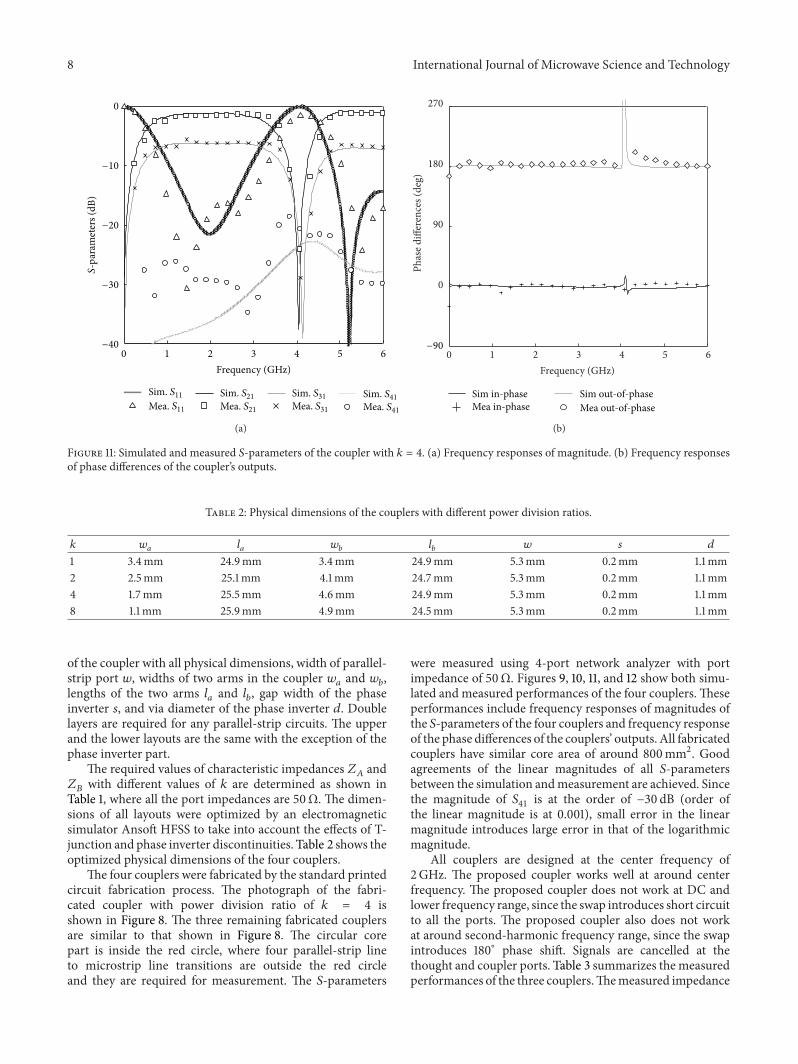
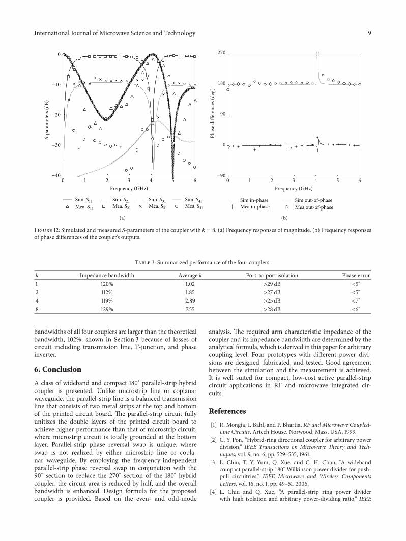

International Journal of
AerospaceEngineeringHindawi Publishing Corporationhttpwwwhindawicom Volume 2014
RoboticsJournal of
Hindawi Publishing Corporationhttpwwwhindawicom Volume 2014
Hindawi Publishing Corporationhttpwwwhindawicom Volume 2014
Active and Passive Electronic Components
Control Scienceand Engineering
Journal of
Hindawi Publishing Corporationhttpwwwhindawicom Volume 2014
International Journal of
RotatingMachinery
Hindawi Publishing Corporationhttpwwwhindawicom Volume 2014
Hindawi Publishing Corporation httpwwwhindawicom
Journal ofEngineeringVolume 2014
Submit your manuscripts athttpwwwhindawicom
VLSI Design
Hindawi Publishing Corporationhttpwwwhindawicom Volume 2014
Hindawi Publishing Corporationhttpwwwhindawicom Volume 2014
Shock and Vibration
Hindawi Publishing Corporationhttpwwwhindawicom Volume 2014
Civil EngineeringAdvances in
Acoustics and VibrationAdvances in
Hindawi Publishing Corporationhttpwwwhindawicom Volume 2014
Hindawi Publishing Corporationhttpwwwhindawicom Volume 2014
Electrical and Computer Engineering
Journal of
Advances inOptoElectronics
Hindawi Publishing Corporation httpwwwhindawicom
Volume 2014
The Scientific World JournalHindawi Publishing Corporation httpwwwhindawicom Volume 2014
SensorsJournal of
Hindawi Publishing Corporationhttpwwwhindawicom Volume 2014
Modelling amp Simulation in EngineeringHindawi Publishing Corporation httpwwwhindawicom Volume 2014
Hindawi Publishing Corporationhttpwwwhindawicom Volume 2014
Chemical EngineeringInternational Journal of Antennas and
Propagation
International Journal of
Hindawi Publishing Corporationhttpwwwhindawicom Volume 2014
Hindawi Publishing Corporationhttpwwwhindawicom Volume 2014
Navigation and Observation
International Journal of
Hindawi Publishing Corporationhttpwwwhindawicom Volume 2014
DistributedSensor Networks
International Journal of