Community-based CCTV Schemes -...
24
An Garda Síochána Telecommunications Section Technical Specification Community-based CCTV Schemes
Transcript of Community-based CCTV Schemes -...

A n G a r d a S í o c h á n a Telecommunications Section
T e c h n i c a l S p e c i f i c a t i o n
Community-based CCTV Schemes
2
CONTENTS
PART 1 - CCTV SYSTEMS TO BE OPERATED BY COMMUNITY BASED GROUPS....... 3
1.1 INTRODUCTION .....................................................................................................................3 1.2 SCOPE OF THIS DOCUMENT ....................................................................................................3 1.3 COMMUNITY-BASED GROUP RESPONSIBILITIES .......................................................................3 1.4 ADDENDUM ..........................................................................................................................3
PART 2 - GUIDANCE NOTES FOR PROSPECTIVE APPLICANTS...................................... 4
2.1 COMMUNITY-BASED CCTV SCHEME......................................................................................4 2.2 GUIDANCE FOR DESIGN OF A COMMUNITY BASED CCTV SCHEME...........................................4 2.3 CONSULTATION.....................................................................................................................4 2.4 OPERATIONAL REQUIREMENT ................................................................................................4 2.5 ANALYSIS .............................................................................................................................5 2.6 IMPLEMENTATION PLAN ........................................................................................................5 2.7 APPLICATION FOR GRANT AID ...............................................................................................5 2.8 INSTALLATION AND COMMISSIONING .....................................................................................5
PART 3 - VIDEO CAMERA AND ASSEMBLY....................................................................... 9
3.1 INTRODUCTION .....................................................................................................................9 3.2 COLOUR DAY/NIGHT CAMERA...............................................................................................9 3.3 ZOOM LENS ........................................................................................................................11 3.4 ENVIRONMENTAL CAMERA HOUSING....................................................................................11 3.5 INFRARED LIGHTING............................................................................................................12 3.6 PAN AND TILT UNIT.............................................................................................................12 3.7 CE COMPLIANCE.................................................................................................................12
PART 4 - TRANSMISSION ......................................................................................................13
4.1 TRANSMISSION METHODS.....................................................................................................13 4.2 SPECIFICATIONS RELATING TO COAXIAL, FIBRE-OPTIC AND MICROWAVE TRANSMISSION. .......14 4.3 RADIO LINKS.......................................................................................................................14
PART 5 - CAMERA SITE - EQUIPMENT AND INSTALLATIONS....................................15
5.1 GENERAL ............................................................................................................................15 5.2 OUTDOOR EQUIPMENT CABINET ..........................................................................................15 5.3 CAMERA MOUNTING BRACKETS...........................................................................................15 5.4 CAMERA COLUMN (POLE) ....................................................................................................15 5.5 CAMERA/EQUIPMENT LOCATION ..........................................................................................16 5.6 CCTV SIGNS ......................................................................................................................16 5.7 ELECTRICAL MAINS SUPPLY ................................................................................................16
PART 6 - MONITORING CONTROL CENTRE ....................................................................17
6.1 CONTROL CENTRE...............................................................................................................17 6.2 MONITORING FACILITIES .....................................................................................................17 6.3 SECURE TAPE AND MEDIA STORAGE CABINETS.....................................................................18 6.4 SYSTEM MANAGEMENT FUNCTIONS .....................................................................................18 6.5 RECORDING /PLAYBACK ......................................................................................................19 6.6 ON-SCREEN TEXT DISPLAY ..................................................................................................20 6.7 VIDEO MATRIX SWITCHING .................................................................................................20 6.8 VIDEO MULTIPLEXING.........................................................................................................21 6.9 VIDEO MONITORS ...............................................................................................................21 6.10 S-VHS TIME LAPSE RECORDING ......................................................................................22 6.11 DIGITAL RECORDING ......................................................................................................23
PART 7 - SERVICES.................................................................................................................24
7.1 WARRANTY ........................................................................................................................24 7.2 MAINTENANCE CONTRACT ..................................................................................................24 7.3 MAINTENANCE / UPGRADING ISSUES ....................................................................................24 7.4 OPERATOR EQUIPMENT TRAINING........................................................................................24

3
PART 1 - CCTV SYSTEMS TO BE OPERATED BY COMMUNITY BASED GROUPS
1.1 Introduction The Department of Justice, Equality & Law Reform intends to grant aid CCTV schemes which meet certain criteria, operated by Community-based Groups. This document outlines the minimum technical/operational criteria, which Community-based CCTV Systems must comply with. Each Community-based Group scheme will generally involve one or more interest groups (stakeholders) representing various sections of the community. Examples of different stakeholders might be:
Local Authority Residents Association
Chamber of Commerce Emergency Services
1.2 Scope of this Document This document provides guidelines and specifications which are to be met by Community-based Groups proposing to establish and operate a CCTV scheme and who wish to be considered for grant aided funding from the Department of Justice, Equality & Law Reform. The first part of the document provides guidance to groups on how they might prepare a statement of operational requirements and the actions required to gain the most appropriate response from the CCTV system. This statement, compiled from each stakeholders requirement, will form an Operational Requirement on which a CCTV system may be designed which best meets the requirements of the Community. The remaining part of the document provides technical guidance and specifications of equipment and operating procedures designed to ensure that picture quality and content meet the requirements of the observers and the Gardai.
1.3 Community-based Group Responsibilities The Community-based proposal will be required to demonstrate it’s technical suitability against the Groups Operational Requirement and Code of Practice. Health and Safety in regard to the overall system, it’s operators/employees and the general public are the responsibility of the Community-based Group.
1.4 Addendum The Commissioner of An Garda Síochána, the Minister for Justice, Equality and Law Reform and all respective servants, and employees thereof accept no liability for any losses or injuries in connection with the works or the ongoing use of the CCTV systems operated by the Community-based Group.

4
PART 2 - GUIDANCE NOTES FOR PROSPECTIVE APPLICANTS
2.1 Community-based CCTV Scheme The scheme has been devised by the Department of Justice, Equality and Law Reform to provide grant aid funding to groups representing local community interests who wish to install and maintain a CCTV system in their area.
2.2 Guidance for Design of a Community Based CCTV Scheme As an aid to designing a scheme, it is recommended that a methodology is adopted in order to plan a scheme which best represents the requirements of the various stake-holders and provides a solution which achieves the benefits which such a scheme is capable of providing.
The basis of any scheme should be an Operational Requirement, completed jointly by the Group. The Operational Requirement will form the basis for the design and operation of an effective and economic system. The methodology recommended here provides a process that identifies key factors, which impact on performance of the system and the way it will be operated.
2.3 Consultation Consultation should be conducted within each area where such a scheme is envisaged. Residents in particular should be fully consulted and informed of the proposal. It is a requirement of the grant aid that residents are broadly supportive of the scheme. Care should be taken on the design of the CCTV scheme to ensure that it is acceptable to local residents regarding the location of equipment and equipment should be deployed so as to avoid any undue intrusion.
2.4 Operational Requirement Each stake-holder of the Group should be encouraged to undertake surveys of their members requirements and compile a Operational Requirement document. In preparing a Operational Requirement, each group or stakeholder should be provided with a plan of the area concerned and an “Operational Requirement Check List” (Appendix “A”) should be compiled and completed in respect of each problem encountered. The observations of each stakeholder are prioritised and a plan or map of the area, appropriately marked by the stakeholder, is drawn up.
The completed “Check Lists” together with the plan or map completed by each stakeholder forms a comprehensive view of the problems encountered by the Group. The combining and prioritising of all the requirements will provide the basis on which the design and operation of the scheme can be formulated.
5
2.5 Analysis From the combined Operational Requirements submitted, the group should be in a position to analyse the submissions and prioritise the requirements. Financial analysis of the plan will need to be undertaken in order to size the plan to best meet the agreed requirements and budgets. Capital costs, running/staffing costs and maintenance should each be factored in. Applicants will need to demonstrate how running costs will be met and that the system is sustainable for at least five years from the date of the installation of the equipment.
Analysis of the individual stakeholder Operational Requirements and a financial analysis will result in the overall Operational Requirement of the Group.
2.6 Implementation Plan The grant awarded by the Department of Justice, Equality and Law Reform is a one off payment for new schemes only. The agreed plan will therefore be implemented as a single plan. Additional phases of a plan will not qualify for grant aid.
2.7 Application for Grant Aid The Group will make application to the Department of Justice, Equality and Law Reform in the format published within the issued Prospectus.
2.8 Installation and Commissioning Following installation of the CCTV system, a full commission and test of the system is carried out to ensure the system meets the specification and the Operational requirements.

6
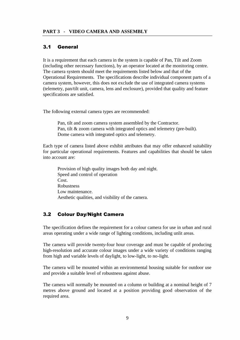
Suggested method to develop a community-based CCTV scheme.
Stakeholder3
Stakeholder2Stakeholder
1 Priority 3
Priority 2
Operational RequirementPriority 1
Priority 3
Priority 2
Operational RequirementPriority 1
Priority 3
Priority 2
Operational RequirementPriority 1
ANALYSIS
Priority 3
Priority 2
Priority 1
Budgetary Costing€ x+y
Budgetary Costing€ x
Implementation Plan
Operational Requirement
Monitoring facility
Code of Practice CommissioningTests
Marked Plan of Area
Application for Grant Aid
Installation andCommissioning
Area PlanArea Plan Area Plan
Financial details &Running Costs
TechnicalSpecification
Maintenance

7
A P P E N D I X “ A ”
OPERATIONAL REQUIREMENT CHECK LIST
INTEREST GROUP ______________________ PLAN REF. NO.________
AREA OF INTEREST ___________________ REF No.________
OBSERVATION
Target to be Observed:
What Activity by the Target is of Concern:
Purpose of the Observation:
Picture Quality/Content factors needed for success:
RESPONSE
When is Observation needed:
Result of a successful Response to the Activity:
Who Makes the Response:
Time scale of the Response for it to be successful:
Conditions under which the system needs to be effective (Lighting/weather):
OBSERVER ROLE
What will the Observer do when the activity occurs:
How will the Observer know when and where to look:
How quickly does the Observer need to act:
CLASSIFICATION
Stake-holders:
i.e. Local Authority
Chamber of Commerce
Residents Association
What Priority is assigned to this task:
Likelihood of an Activity occurring and how often:
Benefits of doing the action over not doing it:

8
Emergency Services
9
PART 3 - VIDEO CAMERA AND ASSEMBLY
3.1 General It is a requirement that each camera in the system is capable of Pan, Tilt and Zoom (including other necessary functions), by an operator located at the monitoring centre. The camera system should meet the requirements listed below and that of the Operational Requirements. The specifications describe individual component parts of a camera system, however, this does not exclude the use of integrated camera systems (telemetry, pan/tilt unit, camera, lens and enclosure), provided that quality and feature specifications are satisfied. The following external camera types are recommended:
Pan, tilt and zoom camera system assembled by the Contractor. Pan, tilt & zoom camera with integrated optics and telemetry (pre-built).
Dome camera with integrated optics and telemetry. Each type of camera listed above exhibit attributes that may offer enhanced suitability for particular operational requirements. Features and capabilities that should be taken into account are:
Provision of high quality images both day and night. Speed and control of operation Cost. Robustness Low maintenance. Aesthetic qualities, and visibility of the camera.
3.2 Colour Day/Night Camera The specification defines the requirement for a colour camera for use in urban and rural areas operating under a wide range of lighting conditions, including unlit areas. The camera will provide twenty-four hour coverage and must be capable of producing high-resolution and accurate colour images under a wide variety of conditions ranging from high and variable levels of daylight, to low-light, to no-light. The camera will be mounted within an environmental housing suitable for outdoor use and provide a suitable level of robustness against abuse. The camera will normally be mounted on a column or building at a nominal height of 7 metres above ground and located at a position providing good observation of the required area.

10
The camera control system will provide a means to restrict intrusive viewing of areas considered or notified as private. In areas with good street lighting the camera will be required to operate normally in colour mode. A location, which suffers poor or non-existent street lighting, will require a camera capable of viewing the required scene and providing a suitable level of recognition. Cameras sited adjacent to unlit areas such as open spaces and rivers are recommended to be capable of operation with Infrared lighting, however in some instances it may be more appropriate to have additional lighting installed or upgraded. The colour camera is required to provide high reliability, capable of operating to specification without the need for constant adjustment, maintenance or repair.
TV Standard CCIR standard 625 lines, 50 fields PAL colour. Effective Picture Elements Not less then 752(H) x 582(V) pixels. Resolution Not less than 450 lines (luminance). Image Quality True colour image representation free of discoloration is
required. Camera Sensitivity
Colour/monochrome camera Better than 1.0 lux for colour images (AGC on). 0.5 lux for monochrome (f1.4).
Integrating camera Better than 0.4 lux (f/1.2 AGC on) for colour images.
Auto Iris Control The camera should provide iris control compatible with
the proposed lens. Video S/N Not less than 48dB at 2.5 lux sensor illumination. AGC Automatic with manual override Focus (if applicable) Automatic with manual override.

11
3.3 Zoom Lens The proposed lens for use at any particular location shall be suitable for providing images of the area and targets as defined in the groups Operational Requirement. The zoom range and focal length (camera dependent), of each lens shall meet the Operational Requirement and taking into account the area plan and the defined image content. The lens shall be a high-resolution type with high transmission efficiency suitable for external daylight and low-light conditions. The lens shall be fully compatible with the proposed camera. The specifications for a motorised zoom lens are listed below. Minimum f-stop F1.4 or better with low ramping over zoom range.
Iris Automatic and remote manual iris control.
Neutral density spot filter.
Maximum Aperture F1.4 ~360
Focus Motorised with pre-sets
Zoom Motorised with pre-sets.
Speed <5 seconds for lens up to10X
<10 seconds for lens up to 20X
The lens shall be of a high quality, with particular emphasis placed on the aperture of the lens for low-light operation and the quality of the electromechanical assembly in terms of operation and expected lifetime reliability. Camera/lens combinations utilising Auto-focus should provide fast tracking of objects and manual override of Auto-focus should be possible.
3.4 Environmental Camera housing The housing shall be designed to IP65 protection and should provide climatic and mechanical protection of the camera, lens and ancillary equipment and cables. It should not obstruct the field of view of the camera. A wiper is required with remote operation. Washer units are not generally required. A heater with automatic thermal switching for optimum climatic control is required.

12
3.5 Infrared Lighting It is recommended that a survey be carried out at each location to identify areas that may benefit from the use of infrared lighting. Areas that can benefit from infrared lighting are those adjacent to open spaces without public lighting and along waterways. When Infrared lighting is considered a requirement, it is recommended a wide-angle flood lamp and a narrow beam spot lamp, selected to provide sufficient illumination over the area is provided. The power and type of the lamps employed should be suitable to meet the Operational Requirement.
3.6 Pan and Tilt Unit Dependent on the camera selected for use at a specific location, the pan & tilt units employed shall be a heavy-duty variable speed type, with high quality bearings, motor control and pre-set potentiometers, capable of long term use. The arc of travel of the platform should be adjustable within specified limits pre-set for each camera location. The pan and tilt unit should be capable of fast, smooth and precise movement with minimal lag or overshoot. The un-powered holding torque should be sufficient to hold a fully fitted camera platform, complete with dual IR lamps (if required), in any position without slippage when subjected to wind speeds of up to 60 mph. The motor and telemetry control shall provide variable speed movement of the camera platform with a pan speed from approximately 6° to 50° per second and a tilt speed of approximately 12° per second. Units providing a wider range then these figures are acceptable provided that the unit is capable of supporting the camera assembly without undue wear and strain on the unit.
3.7 CE Compliance The camera housing assembly, complete with associated components and wiring must bear the CE mark. CE certification of individual component items is not sufficient.

13
PART 4 - TRANSMISSION
4.1 Transmission methods The system proposed for transmission of video signals and telemetry should be based preferably on fibre optic transmission system installed in underground ducting or routed via premises where way-leaves have been obtained. Copper or coaxial transmission of base-band video is to be avoided due to risk of eavesdropping and the inherent loss of image quality associated with these systems. Microwave radio transmission may be utilised dependent on regulatory permission, if it is found that a cabled system is not feasible. The Contractor will be responsible for acquiring any licence necessary on behalf of the Community-based Group. Licence fees may be applicable. Digital transmission over secure broadband systems capable of providing image quality levels meeting the objectives of the Operational Requirement are acceptable provided that real-time monitoring of an activity can be undertaken. On going costs for the provision of cable or duct services attributable to maintenance, licensing and rental charges should be identified and detailed by the Contractor. The system of transmission, especially microwave links should provide a certain level of security against unauthorised monitoring and interference of signals. The Contractor is required to set out and describe the transmission system plan. Guarantees are required that the monitoring centre will be provided with images displaying a high level of signal quality in terms of signal level, interference, noise, bandwidth or image quality and that a high level of link resilience shall be provided. The transmission system should be resilient to all weather conditions frequently experienced in the locality. Radio links should be operated within their specified licensing conditions and distances. Telemetry signalling should be integrated into the video transmission equipment and transmitted over the same medium at a rate not less then 9600bps and provide terminated connections for control via a standard data interface (e.g. RS232, RS422, RS485). Systems employing FSK telemetry shall have the facility to transmit the FSK signals over the transmission medium.

14
4.2 Specifications relating to Coaxial, Fibre-optic and Microwave transmission. Video Bandwidth Not less then 5.6 MHz Video Signal Quality Less then 5% differential gain Less then 5% differential phase Video Signal to Noise Not less then 46dB Video termination 75O terminated BNC input/outputs
PAL composite video input of 1Vp-p.
4.3 Radio Links If radio links are to be employed as part of the system the Contractor must obtain a frequency allocation and licence from the Commission for Communications Regulation (ComReg), Abbey Court, Irish Life Centre, Lower Abbey Street, Dublin1. (Web: www.comreg.ie) The Contractor shall be responsible for the surveying, installation and commissioning of any radio link and site. The Contractor shall be responsible for ensuring compliance with all Licence conditions and safety regulations.

15
PART 5 - CAMERA SITE - EQUIPMENT AND INSTALLATIONS
5.1 General The following specifications cover the general requirements of items and services provided at each camera site. Plans showing the location of cameras, equipment and proposed signal routes and types are to be supplied.
5.2 Outdoor Equipment Cabinet Outdoor equipment cabinets must conform to IP65 for environmental protection and electrical safety. Cabinets fitted in secure locations (not easily accessible to the general public) should be fitted with a standard cabinet lock. Roadside cabinets should be secured with anti tamper fixings in addition to the standard cabinet lock.
5.3 Camera Mounting Brackets It is recommended that cameras be placed at a height of 7 metres above ground. A heavy-duty mounting bracket is required, specifically and individually designed or selected to support the camera assembly on each structure or premises proposed and capable of easily and safely supporting the proposed camera assembly. High quality rust proof materials shall be used in the construction of the brackets, including fixings, bands, nuts, bolts and screws.
5.4 Camera Column (pole) The camera and associated equipment at each location will determine the choice of camera column or pole required. It is recommended that the standard column provide a camera platform height of 7 metres, however, under certain circumstances, a greater or lesser height may be more appropriate. Situations effecting the height of the column are radio “line of sight” issues, camera security considerations or obstacles preventing the camera from viewing a particular scene. The camera poles shall be constructed of galvanised tubular steel in one single column designed to provide a rigid and stable platform for the camera and any additional items such as microwave radio links or equipment. Lattice or tilt-over types are not acceptable.

16
The column shall safely house any transmission/telemetry equipment, electrical mains power supplies and any other items required to be placed within it. An access hatch suitable for installation and service requirements shall be provided. A secure and lockable cover shall be provided. Planning requirements may influence the type of column or pole to be utilised at any location, it is therefore recommended that any specific requirements are established at an early stage with the planning authority.
5.5 Camera/Equipment location The location of cameras and ancillary equipment and cabling in any area and on buildings or structures shall comply with planning requirements and way-leave agreements obtained by the Group.
5.6 CCTV Signs Signs of an appropriate size should be placed so that the public is made aware they are entering an area where CCTV cameras are in operation. The signs should clearly show that CCTV cameras are in operation and identify the organisation legally responsible for the system.
5.7 Electrical Mains Supply The Contractor shall co-ordinate the provision of electrical mains supplies. The ESB publication “National Code of Practice for Customer Interface. 3rd Edition 2002” provides a single interpretation of ESB requirements. This document also covers the electrical supply requirements for CCTV camera installations. Power supplies for cameras and links will be obtained from the electricity supply provider; this will normally be a single-phase 23OV 50Hz AC mains supply. The ESB will require applications for electrical supply from the Community-based Group and satisfactory completion certificates issued by the electrical contractor prior to supply being provided at each site. The ESB will normally issue specific requirements following inspection of each of the camera sites. The installation of the electrical works at each camera site and the consumer unit must meet all ESB and ETCI specifications. The installation of the electrical supply from an agreed supply point and the fitting of consumer units and earth rods will be the responsibility of the Contractor.

17
PART 6 - MONITORING CONTROL CENTRE
6.1 Control Centre The design of the system will provide control of the CCTV system in premises provided by the Community-based Groups.
6.2 Monitoring Facilities As monitoring facilities will vary due to the size and nature of any scheme the following common requirements shall be taken into account in the provision of facilities. The area selected to view the monitors and operate the equipment will be suitable for limiting access only to those responsible for its operation and management and others with legitimate or sufficient reasons for entry. The area should be capable of being secured against unauthorised entry. Viewing of video monitors should not be possible from positions outside this area. Window blinds shall be used to prevent viewing of monitors from outside the building. Procedures and facilities should be put in place to ensure protection against unauthorised access to the area. All monitoring equipment shall meet relevant safety requirements for electrical equipment and installations and be operated within these requirements. The monitoring of the CCTV images shall be carried out having due regard to viewing ergonomics, health and safety and comfort of the CCTV operators. Issues such as viewing angles and distance, lighting / environmental conditions and staff facilities should be satisfactorily met. Suitable ventilation shall be provided to remove heat generated by the CCTV equipment and to maintain good environmental conditions for the operators and equipment. The main areas of heat generation will be from video and computer monitors, video recorders and fibre-optic termination equipment. The capacity of the ventilation system should take into account the quantity and power consumption of the equipment to be installed. Lighting should be provided which aids the viewing of video monitors and which also provides effective light for report writing. The control desk should provide adequate space for CCTV control equipment, radio or telephone equipment, writing space and storage area for log books etc. The video monitors should be positioned so as to prevent light from windows causing reflections on the screens and from shining directly into the operators’ eyes. The size, positioning and number of monitors in a control room will have an effect on the performance of the CCTV operator. Consideration of viewing and operator requirements should be a priority in the design of the control room.

18
The size of the monitor will depend on the level of picture detail and text displayed, the distance of the monitor from the operator and the nature of visual tasks. High-resolution monitors are recommended for these tasks with a horizontal line resolution of at least 650 lines of resolution for 14” to 17” monitors and 550 lines of resolution for monitors of 19” to 21”. LCD and Computer video monitors should display a minimum of 1024 by 768 pixels and provide a wide viewing angle in the horizontal and vertical directions. The monitors may form part of a bank of monitors and should be designed to take into account heat dissipation and electrical/electromagnetic isolation. Power supplies for the CCTV control installation shall meet electrical wiring standards and shall be adequate for all equipment proposed.
6.3 Secure Tape and Media Storage Cabinets A secure lockable cabinet to facilitate 31-days storage of tapes to be secured on the premises is required. This cabinet should be designed in such a way that those responsible for storing and removing tapes can easily identify each designated location slot and tape. Some additional space should be allocated for the storing of spare tapes to replace those removed for evidential purposes or replacement of faulty tapes. A second lockable cabinet for the storage of tapes removed for evidential purposes should also be provided to prevent accidental re-recording. Where Digital recording systems are in use the storage requirements will be sufficient to provide secure storage of media been held off the system up to the 31-day storage requirement and for media retained as evidence.
6.4 System Management Functions Depending on the nature of each CCTV scheme, combinations of equipment offering a range of functions will be proposed by vendors. In order to clearly define the properties and functions required of any system as a whole, the following requirements are to be stipulated. The system shall provide management facilities in the form of restricted user access. The following basic management facilities shall be provided by the system. Manufacturers may well refer to a facility or feature by different names, however, the basic requirements are as listed below.

19
User level set-up Supervisor options and operator options set-up. Camera home positions A facility to program each camera a home position. Privacy zones A facility to program privacy zones per camera. The system is required to
allow the programming of specific areas viewed by the camera as a privacy zone. This area when defined, will be viewable under wide angle viewing of the scene, however if an operator attempts to zoom in on the specific area, the image is required to distort, blackout or auto-pan away from the area.
Camera set-up
Camera on-screen displays and remote camera set-up and maintenance should be provided.
System functions
Privacy zones Home position, Timed patrolling Alarm recording Operator management and passwords
Operator Functions Camera selection with switched viewing on spot monitor.
Camera Pan & Tilt Lens Zoom, Focus, Iris Auto and Manual Lighting On/Off/Auto Washer/Wiper Pre-set positioning and patrols
The camera control system either in the form of a keyboard/joystick or graphical user interface will provide the operator with control of the camera functions and functions of the multiplexer/matrix system including any proprietary functions offered to enhance system performance. Each operators camera controller will interface to the video multiplexer/matrix or digital recording system, enabling a selected camera to be viewed on a spot monitor and recorded on an event recorder as required.
6.5 Recording /Playback Proposals employing either Analogue or Digital based recording systems are acceptable. The recording rate for each camera shall not be less than one (1) frame per second.

20
It is recommended in the case of analogue tape recording, that the recording mode in use will not more then the 12-hour mode setting. A suitable number of recorders to achieve the above recording rate with the specified number of cameras shall be provided. One video recorder for real-time event recording shall be provided. Or in the case of digital recording, playback of the operators spot monitor at full resolution, at a high recording rate is required.
The system is required to provide a playback facility to allow reviewing of recordings. It is recommended that the playback area is located away from the monitoring area to facilitate in-private viewing of recordings. The system should provide a suitable connection point to provide evidential copying of images to tape or the connection of a printer for evidential purposes. Digital recorders should preferably provide a PAL composite and/or y/c output for copying purposes Alternatively, a copy facility should be provided such as CD-ROM, DVD or file-transfer via standard system interfaces. Playback and interface software, whether of a proprietary nature or not, should be provided as part of the system. In the case of analogue recording, high quality S-VHS SE180 tapes shall be used to ensure highest quality recording. It is recommended that videotapes be replaced after 12 recording cycles.
6.6 On-screen Text Display A character generator providing burnt-in on-screen camera identification and time/date information shall form part of the system. The following information shall be imposed on each camera image and recorded: -
Camera identification number or title Time and Date
Optional: Location (scene viewed, street or area name) A feature to have the named location change according to the general direction the camera is currently viewing is optional.
6.7 Video Matrix Switching Where it is envisaged that a matrix function will be required to provide various functions and to facilitate event recording, playback etc. The switch shall provide sufficient capacity to facilitate all video-switching requirements proposed. The system should allow for an additional percentage of capacity initially and should be supplied in a configuration that allows economical expansion of the system, should this arise.

21
6.8 Video Multiplexing
Multiplex or time-lapse recording equipment shall be installed with the capacity to record each camera in the system at a rate of not less then 1 frame per second per camera. The multiplex or time-lapse recording systems shall provide image stabilisation systems to achieve a high degree of image quality. Duplex operation of the recording equipment to enable simultaneous recording and playback shall be provided. Larger systems shall provide dedicated playback facilities. To achieve a minimum recording rate of 1 frame per second per camera over the recommended 12-hour period with SE-180 videocassettes, care should be taken in the number and selection of appropriate multiplexers and recorders. The Contractor shall describe the multiplexer and recording system proposed. Features Activity detector. Time base correction. Alarms. Record Field Rate 50 fields per second. Video In/Out 1 Vp-p 75Ω BNC terminated.
Duplex Operation The multiplexer should allow the operator to playback a
recorded tape without disrupting the recording process. Television System 625 line 50 Hz PAL CCIR
6.9 Video Monitors Video System 625 line CCIR PAL Video Inputs 1 Vp-p 75Ω BNC with loop-through and 75Ω
termination switch. Controls Chroma, Brightness, Contrast. Display CRT Horizontal Resolution 35cm (14”) to 44cm (17”) - Better then 650 lines 53cm (21”) - Better then 550 lines LCD monitor 1024 by 768 pixels

22
6.10 S-VHS Time lapse recording Analogue systems shall use S-VHS time-lapse recording systems. Multiplexed and live event recording shall be operated in the S-VHS mode. Tape Format S-VHS. Television System 625 line, 50 field PAL Colour signal. Recording Modes Time-lapse S-VHS 12-hour time-lapse recording or better in terms of
recorded image quality and required camera recording rate (One image per camera per second).
Event recording S-VHS 3-hour mode. Horizontal Resolution 400 lines or better. Signal to Noise Ratio Video : Better than 40 dB Video Inputs/Outputs 75 Ohm unbalanced 1V peak to peak. BNC Composite video input / output

23
6.11 Digital Recording Digital recording systems are required to meet the following requirements. Stored Image Quality Picture quality and resolution should be equivalent to or
exceeding that of S-VHS 12-hour time-lapse recording.
Recording rate Not less then 1 image per camera per second for each camera in the system.
Storage medium Internal buffered store with archival system maintained external to the system.
Monitoring The system should provide multiple screen and single screen viewing of camera inputs. A spot monitor video output should be provided. The image quality of the spot monitor output should be high quality, live 25 frames per second video image.
Media Copy Output It is preferable that a PAL composite or y/c video output from the system suitable for transferring selected digital images (video and stills) to other formats is provided. The transferred image should show the full screen image of the originally recorded picture image. Alternatively, a copy facility should be provided such as CD-ROM, DVD or file-transfer via standard system interfaces. Playback and interface software, whether of a proprietary nature or not, should be provided as part of the system.
Playback/Search The recorder should allow duplex operation. The system shall be capable of search and playback of recorded images while maintaining full recording of cameras.
Controls Record, Play, Fast/Slow Forward and Rewind, Pause.
Search Facilities By Time/Date and camera number of both internal buffer storage and archived recordings.
Archive The archival system and procedures should provide storage of all images recorded by the system for a period of 31 days and for destruction of images older than the specified number of days unless required for crime investigation and evidential purposes by An Garda Síochána.
Media/Format The archival media, format and image capacity should be described and details provided. Authentication, Encryption and compression systems should be described and details provided. Facilities required for viewing archival media, without access to the Monitoring Site equipment and facilities, should be described.

24
PART 7 - SERVICES
7.1 Warranty The warranty period should be stated and should cover a period of not less than twelve months from commissioning and acceptance of the system. A detailed general maintenance plan for the CCTV system is to be included in the proposal. During the warranty period, such works as required by to maintain the system in full order are to be carried out on a regular basis as detailed in the proposal. During the warranty period, malfunctions or defective works forming part of the installation will be the responsibility of the Contractor to repair, replace or to carry out such works as required to maintain full functionality of the system. Maintenance during the warranty period is to be carried out on a regular basis as detailed in the proposal.
7.2 Maintenance Contract It is recommended that a maintenance contract be put in place to ensure the system is maintained in full working order. The contract should include the provision of a regular maintenance schedule and maintenance callout procedure with suitable response times. The Contractor will be required to hold a supply of recommended spare parts for maintenance purposes. The proposed maintenance contract and recommended spare parts list shall be submitted with the proposal.
7.3 Maintenance / Upgrading Issues The overall Tender price shall cover any software upgrades or software-configuration changes that may be required during the warranty period following commissioning.
7.4 Operator Equipment Training All personnel employed as operators or supervisors shall receive training in the use of the equipment. Operator training shall be provided by the Contractor and will provide the participant with a thorough working knowledge of the system.