dust collectors and combustible dust strategies - odms.net.au

© 2018 Fire Protection Research Foundation
1 Batterymarch Park, Quincy, MA 02169-7417, USA Email: [email protected] | Web: nfpa.org/foundation
Combustible Dust Flame Propagation and Quenching in Pipes and Ducts FINAL REPORT BY:
Alexander Ing National Fire Protection Association, 1 Batterymarch Park, Quincy, Massachusetts, USA. December 2018
TECHNICAL NOTES

—— Page ii ——
---page intentionally left blank---

iii
FOREWORD A technical basis is required for determining when pipes or ducts are too small in diameter to
permit the propagation of combustible dust deflagrations. This must be evaluated considering the
characteristics of the equipment system (pipe/duct diameter and length), properties of the
combustible dust, and operating conditions (pressure, temperature, flow rate, etc.). The
knowledge will permit establishing rational protection requirements in NFPA’s various
combustible dust fire and explosion prevention standards. There is also a lack of knowledge
around conditions influencing the explosion propagation through piping, especially small diameter
piping. Having a clear understanding of experimental testing data would allow analysis to see
what conditions and parameters will affect the explosion propagation and also point out where
there are knowledge gaps.
This comprehensive literature review project seeks to identify the parameters affecting flame
propagation involving combustible dusts within pipes and ducts, and seeks to determine the
conditions under which a combustible dust flame will not propagate (i.e., will quench) within a
piping or ductwork system. The following tasks have been carried out for this project:
1) Identify the conditions under which combustible dust deflagration will not propagate
within a piping or duct work system.
2) Identify the factors (pipe diameter, pipe length, dust type, and dust concentration)
affecting the explosion propagation through pipes from relevant literatures.
3) Identify the gaps from previous studies in the literature and in previous data
compilations.
4) Prepare a final report based on the information gathered from tasks 1, 2 and 3.
The Fire Protection Research Foundation expresses gratitude to the report author Alexander Ing,
who is with National Fire Protection Association located in 1 Batterymarch Park, Quincy, MA,
USA. The Research Foundation appreciates the guidance provided by the Project Technical
Panelists, and all others that contributed to this research effort. Thanks are also expressed to the
National Fire Protection Association (NFPA) for providing the project funding through the NFPA
Annual Research Fund.
The content, opinions and conclusions contained in this report are solely those of the author and
do not necessarily represent the views of the Fire Protection Research Foundation, NFPA,
Technical Panel or Sponsors. The Foundation makes no guaranty or warranty as to the accuracy
or completeness of any information published herein.
About the Fire Protection Research Foundation
The Fire Protection Research Foundation plans,
manages, and communicates research on a broad
range of fire safety issues in collaboration with
scientists and laboratories around the world. The Foundation is an affiliate of NFPA.

iv
About the National Fire Protection Association (NFPA)
Founded in 1896, NFPA is a global, nonprofit organization devoted to eliminating death, injury, property and economic loss due to fire, electrical and related hazards. The association delivers information and knowledge through more than 300 consensus codes and standards, research, training, education, outreach and advocacy; and by partnering with others who share an interest in furthering the NFPA mission. All NFPA codes and standards can be viewed online for free. NFPA's membership totals more than 65,000 individuals around the world.
Keywords: combustible dust, flame propagation, quenching, pipes, ducts, deflagration index.
Report number: FPRF-2018-15
Project manager: Sreenivasan Ranganathan, FPRF

v
PROJECT TECHNICAL PANEL
Andrew Ryerson, FM Global.
Bill Stevenson, CV Technology.
David Kirby, Baker Risk.
Guy Colonna, NFPA.
James Koch, The Dow Chemical Company.
Jerome Taveau, Fike Corporation.
Laura Moreno, NFPA.
Samuel Rodgers, Honeywell.
Walt Frank, Frank Risk Solutions Inc.
PROJECT SPONSORS
National Fire Protection Association (NFPA)

vi
---page intentionally left blank---

vii
EXECUTIVE SUMMARY
Technical research is needed to support industry practice in explosion protection of piping
and duct work. This literature review report seeks to identify the parameters affecting flame
propagation involving combustible dusts within pipes and ducts, and seeks to determine the
conditions under which a combustible dust flame will not propagate (i.e., will quench) within a
piping or ductwork system. Dust deflagrations in piping and ductwork smaller than four inches
does occur and can be confirmed through a number of studies, proving experimentally, that
deflagration in small diameter piping and ductwork is possible. It should also be noted that even
though flame propagation through small diameter piping and ductwork is possible in many cases,
the likelihood of a propagation goes down as the diameter decreases.
For systems that contain dusts in piping and ductwork there are two general categories that
emerge when studying how dust deflagrations interact with explosion protection of these
systems. The first category are the parameters of the dust in the system. Properties such as Kst,
MEC, MIE, and diameter of the dust particles all affect how the dust will behave in the system
and determine deflagration properties such as quenching length and maximum explosion
pressure. Beyond the properties of the dust itself, dust concentration in the system is clearly
important with regard to propagation. The second category are the parameters of the piping and
ductwork, mainly conveying velocity and materials of construction. It was found that through
review of the NFPA dust documents, deflagration protection and prevention documents, and the
flammable and combustible material conveying documents that those documents contain
prescriptive minimum requirements for safe pneumatic conveying of dusts. The other key finding
is how the physical phenomena of a dust deflagration makes it hard to prevent deflagration
propagation or re-ignition without some form of isolation. This is because of the heterogonous
burning of the dust, when turned into a product of combustion there is still a hot solid particle
that can convey in the air and further travel down piping. The current knowledge gaps and
possible future research needs are also presented in the report.

viii
---page intentionally left blank---

1
Table of Contents
List of Figures ................................................................................................................................................ 1
List of Tables ................................................................................................................................................. 2
Introduction .................................................................................................................................................. 3
Objective ....................................................................................................................................................... 4
Background ................................................................................................................................................... 4
NFPA Codes and Standards ....................................................................................................................... 5
Dust Parameter Information ......................................................................................................................... 8
Deflagration index, Kst ............................................................................................................................... 8
Ignition .................................................................................................................................................... 11
Strength and location of Ignitions ....................................................................................................... 13
Minimum Explosible Concentration (MEC) ............................................................................................. 16
System Parameters for dust conveying systems ........................................................................................ 18
Conveying Velocity .................................................................................................................................. 18
Materials of Construction ....................................................................................................................... 19
Dust Quenching ....................................................................................................................................... 19
Table 7: Diameter Size versus Flame Propagation. ................................................................................. 20
Summary of Key Findings ............................................................................................................................ 21
Knowledge Gaps and Next Steps: ............................................................................................................... 22
Annex 1: Summary of Test Methodology ................................................................................................... 26
Annex 2: Selected Annotated Bibliography ............................................................................................ 27
Annex 3: Summary of Literature Review .................................................................................................... 30
References: ................................................................................................................................................. 33
List of Figures Figure 1: Schematic of lumped capacitance assumption for layers and one-dimensional heat transfer to
walls (reproduced from Bidabadi et al. (Recreated from Bidabadi et al.) .................................................. 15
Figure 2 Explosion pressure data for high volatile bituminous (hvb) coal and polyethylene dusts,
compared with those methane gas12 (Recreated from Eckhoff) ................................................................ 17

2
List of Tables Table 1: Examples of Kst Values for Different types of Dusts. Reproduced from the OSHA Standard on
Combustible Dusts ........................................................................................................................................ 9
Table 2: Pneumatically conveyed dust deflagration flame velocities (152.4 MM Pipe) Reproduced from
[4] ................................................................................................................................................................ 10
Table 3 Ignition temperature as a function of particle diameter (Reproduced from Marino)8 ................. 11
Table 4: Influence of initial turbulence on explosion rate of a dust cloud10 (Reproduced from Shoshin et.
al.) ............................................................................................................................................................... 13
Table 5: Influence of initial turbulence (turbulence at the moment of ignition) on minimum electric spark
ignition energy (MIE) of a dust cloud. Experiments with various dusts in a 20-litre closed explosion
bomb9 (Reproduced from Shoshin et. al.) .................................................................................................. 14
Table 6: Influence of average dust concentration on the minimum electric spark ignition energy (MIE) of
clouds of an anti-oxidant in air, in the standard 1-m3 closed vessel9 (Reproduced from Shoshin et. al.) . 16
Table 7: Diameter Size versus Flame Propagation. ..................................................................................... 20

3
Introduction
Dust has always been a unique hazard in the fire protection world. When lofted into the air and
ignited, dusts can burn vigorously, producing heat and, when confined, pressure that can harm
people and damage property and equipment. Unfortunately, incidents involving fires and
explosions are not uncommon, and there have been 281 incidents between 1980 and 2005 that
have killed 119 workers and injured 718, according to the Chemical Safety Board (CSB) (2005)1 ,
with many more occurring in the 13 subsequent years. Well known incidents such as the dust
explosion at the Imperial Sugar Refinery in Port Wentworth, Georgia have caused numerous
deaths, 14 in the case of the Imperial Sugar refinery, and millions of dollars in property loss. The
hazard dust poses is not limited to one industry and can commonly occur in industries such as
food processing, pharmaceutical, metal processing, wood processing, and many other industries.
In response to this ever-present need for dust deflagration and explosion prevention and
mitigation codes and standards organizations (e.g., National Fire Protection Association (NFPA))
and regulatory agencies (e.g., Occupational Safety and Health Administration (OSHA)), have
developed a number of standards and guidelines to help manage the risk of dust deflagrations or
explosions. The NFPA dust standards (e.g., NFPA 654: Standard for the Prevention of Fire and
Dust Explosions from the Manufacturing, Processing, and Handling of Combustible Particulate
Solids, and NFPA 652: Standard on the Fundamentals of Combustible Dust) seek to control the
hazards of combustible dusts through the prescription of both active and passive methods of
dust fire and explosion protection. These standards often contain prevention knowledge based
on both industry best practice and technical data gathered from research. Standards are
intended to define the minimum level of safety and should be based on proven science and
research.
One instance where technical research is needed to support an industry practice is explosion
protection of piping and duct work, specifically in small diameter piping and duct work. NFPA 654
1 U.S. CSB. (2010). Investigation Report, COMBUSTIBLE DUST HAZARD STUDY. U. S. Chemical Safety and Hazard Investigation Board. DOI: https://doi.org/REPORT NO. 2006-H-1

4
previously contained language specifying that explosion protection was not required for small
diameter piping and met other requirements such as not conveying a metal dust or hybrid
mixture (see NFPA 654 7.1.6.2 2013). However the technical committee for NFPA 654 removed
this exception after determining that there was not enough technical data to substantiate
waiving a requirement for explosion protection on small diameter piping in addition to the other
factors in the requirement.
Objective
This comprehensive literature review project seeks to identify the parameters affecting flame
propagation involving combustible dusts within pipes and ducts, and seeks to determine the
conditions under which a combustible dust flame will not propagate (i.e., will quench) within a
piping or ductwork system. The following tasks have been carried out for this project:
1) Literature Review I: Identify the conditions under which combustible dust deflagration will
not propagate within a piping or duct work system.
2) Literature Review II: Identify the factors (pipe diameter, pipe length, dust type, and dust
concentration) affecting the explosion propagation through pipes from relevant literatures.
3) Identify Gaps: Identify the gaps from previous studies in the literature and in previous data
compilations.
4) Final Report: Publish a final report based on the information gathered from tasks 1, 2 and 3.
Background
Fire requires three elements known to start and continue, which are fuel, oxidizer, and heat.
These three elements are often depicted as the fire triangle any fire will always have these three
elements and, if any one side of the triangle is removed, then the fire will die out. Dust explosions
require two additional elements, dispersion, and confinement, to create the dust explosion
pentagon. Dispersion is required to create a combustible dust cloud, and confinement is required
to allow pressure to accumulate to a potentially damaging level. In terms of this project, piping

5
and ductwork will establish containment for dust clouds, and depending on the type of piping or
duct work (e.g., pneumatic conveying), dust will also be dispersed into the air. Thus for this
project it is more than reasonable to assume that there is a chance for both fire and explosion,
compared to normal scenarios of general dust accumulation and dispersion.
Dust has both the ability to deflagrate and detonate. According to NFPA 68: Standard on
Explosion Protection by Deflagration Venting, 2018 Edition, Deflagration is the “Propagation of a
combustion zone at a velocity that is less than the speed of sound in the unreacted medium” while
detonation is the “Propagation of a combustion zone at a velocity greater than the speed of sound
in the unreacted medium”. Typically, flame propagation happens by the transfer of heat from the
reaction zone to the reactants. Flame speed is the speed of the flame front relative to a fixed
reference point. At a minimum, the flame speed is equal to the fundamental burning velocity
times an expansion factor related to the density ratio of the unburned gas to the burned gas.
Burning velocity is the rate of flame propagation relative to the velocity of the unburned gas
ahead of it and fundamental burning velocity is the burning velocity of a laminar flame under
stated conditions of composition, temperature, and pressure of the unburned gas. These two
methods of measurement also allow a standard method of comparison between different tests
and experiments.
NFPA Codes and Standards
The NFPA has been developing combustible dust codes and standards since the 1920s and
through the ANSI standards process, has brought together multiple technical committees of
various interest categories to responsibly develop safety codes and standards based off of best
industry practices, research, and subject matter expertise. These codes have become generally
accepted within industry. In order to provide the best deliverable the following definitions have
been extracted from NFPA codes. [© copyright NFPA]. The extract tags below provide the NFPA
document number first, section number second, and the edition year last.

6
Minimum Explosible Concentration (MEC): The minimum concentration of a combustible dust
cloud that is capable of propagating a deflagration through a uniform mixture of the dust and air
under the specified conditions of test [NFPA 68 3.3.22 2018]
Minimum Ignition Energy (MIE): The minimum amount of energy release at a point in a
combustible mixture that causes flame propagation away from the point, under specified test
conditions. [NFPA 68 3.3.23 2018]
Hydraulic Diameter: A diameter for noncircular cross sections that is determined by 4 (A/p),
where A is the cross-sectional area normal to the longitudinal axis of the space and p is the
perimeter of the cross section. [NFPA 68 3.3.19 2018] In this paper when pipe is referred to it
means a circular pipe with a set diameter, while ductwork refers to square or non-circular piping.
When diameter is used in relation to ductwork for this paper it is the hydraulic diameter.
Isolation: A means of preventing certain stream properties from being conveyed past a
predefined point [NFPA 69 3.2.24 2014]. When isolation is referred to in this paper it covers
generally all forms of isolation as there are various properties that need to be stopped from being
transmitted down the full length of piping or ductwork and into another area or vessel. NFPA 69:
Standard on Explosion Prevention Systems lists four types of isolation, chemical, deflagration,
flow, and ignition source isolation. Deflagration and ignition source isolation are highlighted
below as they are the two types of isolation that are important to keep in mind for the results
section.
Deflagration Isolation: A method employing equipment and procedures that interrupts
the propagation of a deflagration flame front past a predetermined point. [NFPA 68
3.3.24.2 2018]

7
Ignition Source Isolation: A method employing equipment and procedures that interrupts
the propagation of an igniting medium past a predetermined point [NFPA 68 3.3.24.4
2018]
The goal of quenching a deflagration is to prevent that flame from igniting further reactants and
further causing any damage to interconnected equipment. If a flame continues to propagate
down the pipe and fails to quench, deflagration isolation will be necessary. If a flame is quenched
by the small diameter of the piping, then the products of combustion or the preheated dust
particles that remain, could ignite other dust particles further along in the pipe or in a vessel
downstream. This is possible because the burning characteristics of dust deflagrations (e.g.
heterogeneous burning) can change with the properties of the dust cloud in the piping. For
example, if the flame is quenched and the remaining products continue to travel to a wider
section of pipe where the dust concentration or geometry is different, the flame might reignite.
Thus, ignition source isolation would be necessary to prevent this potential occurrence.
Duct: Pipes, tubes, or other enclosures used for the purpose of pneumatically conveying
materials. [NFPA 91 3.3.4 2015] While NFPA 91: Standard for Exhaust Systems for Air Conveying
of Vapors, Gases, Mists, and Particulate Solids, 2015 Edition has the above definition, for this
paper ducts and pipes will be separated out for clarity. This is because, while similar in purpose
and construction (i.e. physically confined spaces), the geometries are different and a majority of
the research found in the literature review specifically focused on piping.
The literature gathered through this review were sorted into three broad categories in order to
better organize and disseminate the information gathered. The three categories are as follows:
1. Dust Parameter Information,
2. Dusts in Piping and Ductwork, and
3. Dust Flame Quenching.
Literature in the Dust Parameter Information category discusses the parameters that propagate
a dust fire or explosion, as well as how the fire or explosion is affected. Methods of dust ignition

8
in general and in piping and ductwork scenarios are included in this category. The Dust in Piping
and Ductwork category contains all the literature with either experimental or modeling data that
looks into the deflagration or detonation of dusts in piping or duct work. The literature in this
category has technical data examining some aspect of how dusts interact with piping and
ductwork. The third category, Dust Flame Quenching, groups together the literature that
discusses how dust flames can be quenched, in both piping and duct work. Annex. 3 provides a
summary table of all the reviewed sources, while Annex. 2 provides an annotated extract of
certain key sources reviewed in this study.
Dust Parameter Information
As mentioned in the background, dust flame propagation requires each of the three sides of the
fire triangle; fuel, oxygen, and heat. Dust parameters affect how these three elements come
together to propagate flame. Propagating a flame in a gas is easier than propagating a flame in a
dust mixture since it requires one more leg of the dust pentagon (dispersion) and it is also highly
dependent on the parameters of each specific dust. It should also be noted that dusts with similar
properties. For this paper, the quenching distance will be defined as the minimum pipe diameter
or ductwork wall distance required to prevent flame propagation2,3. This would be analogous to
the term quenching diameter as most of the literature reviewed focuses on piping systems which
have a diameter. Quenching length would be the length the flame front travels down the tube
before quenching. Dust deflagration quenching involves loosing enough heat to the walls of the
pipe or duct so that the combustion front is interrupted and extinguishes
Deflagration index, Kst
The dust deflagration index (Kst) is the normalized maximum rate of pressure rise. It measures
the relative explosion severity compared to other dusts, with larger values of Kst being
2 Chao, C. Y. H., Hui, K. S., Kong, W., Cheng, P., & Wang, J. H. (2007). Analytical and experimental study of premixed methane-air flame propagation in narrow channels. International Journal of Heat and Mass Transfer, 50, 1302-1313 3 Law, C. K. (2006). Combustion physics. New York, USA: Cambridge University Press.
9
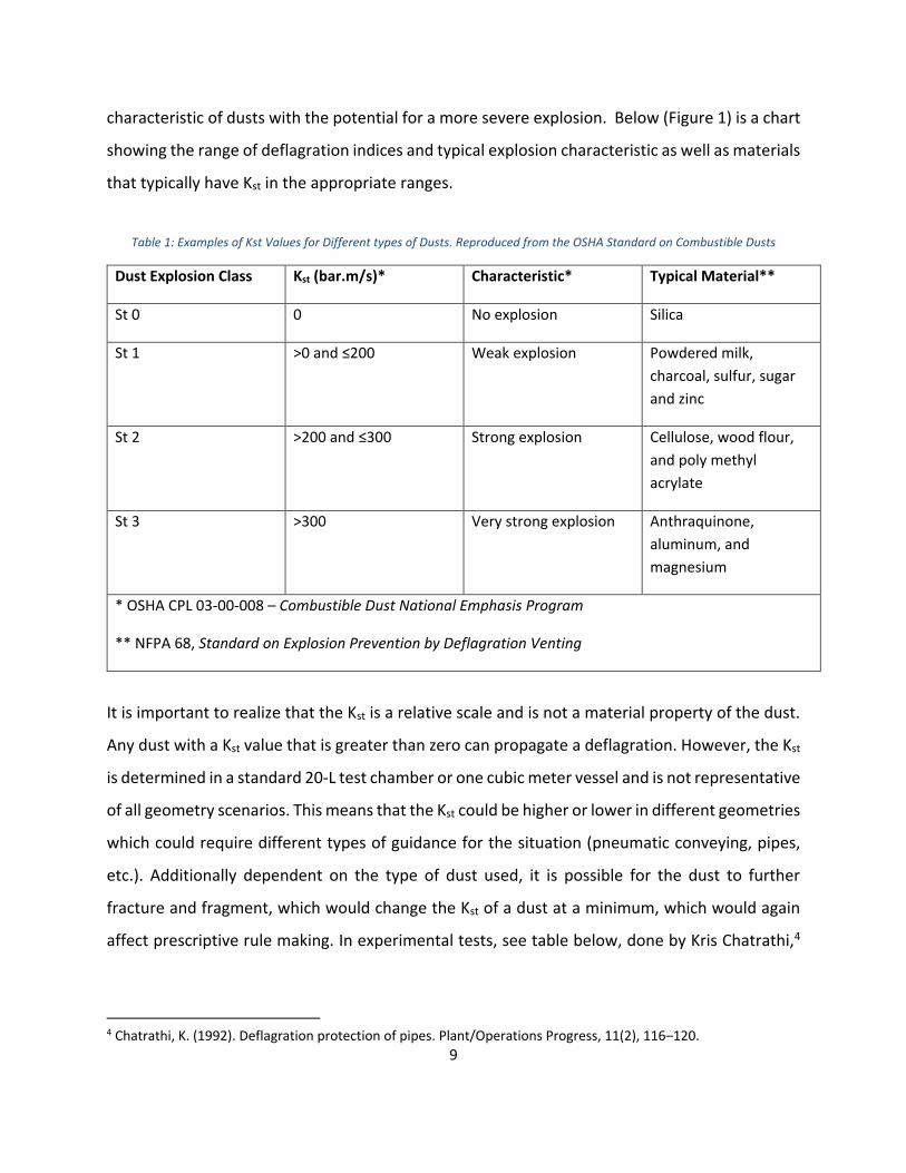
characteristic of dusts with the potential for a more severe explosion. Below (Figure 1) is a chart
showing the range of deflagration indices and typical explosion characteristic as well as materials
that typically have Kst in the appropriate ranges.
Table 1: Examples of Kst Values for Different types of Dusts. Reproduced from the OSHA Standard on Combustible Dusts
Dust Explosion Class Kst (bar.m/s)* Characteristic* Typical Material**
St 0 0 No explosion Silica
St 1 >0 and ≤200 Weak explosion Powdered milk,
charcoal, sulfur, sugar
and zinc
St 2 >200 and ≤300 Strong explosion Cellulose, wood flour,
and poly methyl
acrylate
St 3 >300 Very strong explosion Anthraquinone,
aluminum, and
magnesium
* OSHA CPL 03-00-008 – Combustible Dust National Emphasis Program
** NFPA 68, Standard on Explosion Prevention by Deflagration Venting
It is important to realize that the Kst is a relative scale and is not a material property of the dust.
Any dust with a Kst value that is greater than zero can propagate a deflagration. However, the Kst
is determined in a standard 20-L test chamber or one cubic meter vessel and is not representative
of all geometry scenarios. This means that the Kst could be higher or lower in different geometries
which could require different types of guidance for the situation (pneumatic conveying, pipes,
etc.). Additionally dependent on the type of dust used, it is possible for the dust to further
fracture and fragment, which would change the Kst of a dust at a minimum, which would again
affect prescriptive rule making. In experimental tests, see table below, done by Kris Chatrathi,4
4 Chatrathi, K. (1992). Deflagration protection of pipes. Plant/Operations Progress, 11(2), 116–120.

10
he noted that a correlation between Kst and flame velocity could not be made as dusts with a
higher Kst had a lower flame velocity consistently.
Table 2: Pneumatically conveyed dust deflagration flame velocities (152.4 MM Pipe) Reproduced from [4]
Other literature5,6 also concludes that the link between correlations of Kst and deflagration or
maximum deflagration pressure cannot be accurately made, as their results and analysis revealed
that under the same experimental conditions different dusts with the same Kst have different
explosion intensity. Thus deflagration strength cannot be accurately tied to Kst in piping and duct
work in instances where there are no vented vessels. While Kst cannot be used to conclusively
prove deflagration strength in piping or duct work in a rigorous manner for guidance, it can be
noted that as the magnitude of Kst increases, the ease of flame propagation in the tube will go
up. 7
5 Taveau, J. (2013). Dust explosion propagation: myths and realities. DOI:https://doi.org/10.1016/j.jlp.2017.04.019 6 Proust, C. (1996). Dust explosions in pipes: A review. Journal of Loss Prevention in the Process Industries, 9(4), 267–277. DOI: https://doi.org/10.1016/0950-4230(96)00010-1 7 Holbrow, P., Andrews, S., & Lunn, G. A. (1996). Dust explosions in interconnected vented vessels. Journal of Loss Prevention in the Process Industries, 9(1 SPEC. ISS.), 91–103. DOI: https://doi.org/10.1016/0950-4230(95)00055-0
Dust Kst (bar m/s) Air Velocity (m/s) Flame Velocity
Cornstarch
214
6.86 106
11.43 64
17.78 73
Calcium Stearate
302
6.86 98
11.43 56
17.78 70

11
Ignition
If ignited, the deflagration or explosion strength is affected by a number of other ignition factors
such as ignition location, ignition strength, and type of ignition. Ignition is important for any dust
flame propagation, however the strength of the ignition source can determine whether the dust
cloud ignites, does not ignite, or over ignites which can change the flame dynamics of the system.
The ignition of a dust is dependent on heat transfer in terms of how fast or how slowly energy
can reach the suspended dust particles dictating the time to ignition. In a piping or ductwork
system there are heat transfers from the flame front to three areas; (1) between the dust
particulates, (2) the walls of the system, and (3) the conveying media.
To ignite a single particle it is necessary for heat to transfer into the particle to reach the ignition
temperature. According to the works of Marino8 and Bidabadi et al.9 there is a clear relationship
between ignition temperature and particle diameter as can be seen in the graph below. Larger
the particle diameter, the higher ignition temperature required.
Table 3 Ignition temperature as a function of particle diameter (Reproduced from Marino)8
Particle Diameter (millimeters) Ignition Temperature (K)
6.50 975
9.92 1183
19.90 1497
29.73 1819
Logically this correlation makes sense as the larger the particle the more energy is required to
heat it to the ignition point. Since this increase in particle diameter will also affect other
8 Marino, T. A. (2008). Numerical analysis to study the effects of solid fuel particle characteristics on ignition, burning, and radiative emission. Thesis (PhD), The George Washington University 9 Bidabadi, M., Zadsirjan, S., & Mostafavi, S. A. (2013). Propagation and extinction of dust flames in narrow channels. Journal of Loss Prevention in the Process Industries, 26(1), 172–176. DOI:https://doi.org/10.1016/j.jlp.2012.10.009

12
parameters such as the conveying velocity necessary to keep the particle dispersed and the MEC;
it is necessary that those parameters be considered when making decisions on particle size. If
particle size is increased to prevent ignition by increasing the minimum amount of energy
required, the particle might no longer pneumatically convey the same or have the same
calculated explosible concentration. Shoshin et al.10 also correlated burning time to particle
diameter for aluminum dusts where burning time of the particle (τ) was correlated to the
following function,
τ [sec]= 310 Dp, where Dp is the particle diameter in meters.
Burning time will affect how effectively dust flame is quenched in piping and duct work as
particles that are still smoldering could later ignite further along in the piping or duct work even
after flame has been quenched.
Strength of the ignition source does play a role in determination of dust ignition and propagation.
It is entirely possible that a dust when exposed to a weaker ignition source (e.g. electrostatic
spark) does not ignite or have strong propagation, while when exposed to a stronger chemical
ignitor or larger flame, the dust will ignite and propagate. Tests currently use a variety of ignition
sources dependent on the industry, and the choice of ignition source should reflect the
appropriate hazard in the system.11 Maximum deflagration pressure versus dust turbulence can
be seen in the graph below and shows that initial turbulence will increase the maximum
deflagration pressure. For example if while pneumatically conveying a dust or collecting a dust
the air velocity is high but not high enough to prevent propagation of a flame front, the highly
turbulent conditions could favor a stronger deflagration.
10 Shoshin, Y. L., & Dreizin, E. L. (2006). Particle combustion rates for mechanically alloyed Al - Ti and aluminum powders burning in air. Combustion and Flame, 145, 714-722 11 Cashdollar, K. L. (2000). Overview of dust explosibility characteristics. Journal of Loss Prevention in the Process Industries, 13(3–5), 183–199. DOI: https://doi.org/10.1016/S0950-4230(99)00039-X

13
Table 4: Influence of initial turbulence on explosion rate of a dust cloud10 (Reproduced from Shoshin et. al.)
Delay between dust dispersion and ignition (ms) (dP/dt)max (bar/s)
162.03 316.82
199.04 429.80
246.75 313.41
331.51 325.71
421.44 155.78
542.66 70.58
593.44 48.42
700.72 32.37
771.31 29.01
824.97 28.83
872.98 25.54
906.85 19.15
946.39 19.02
Strength and location of Ignitions
Spark ignitions are also susceptible to variation in required energy to spark different dust clouds,
as difference in sparker traits can lead to MIE that are order of magnitudes different from one
another.12 Thus the ignition source strength and type should reflect the scenario the dust is
exposed to as the maximum deflagration pressure could greatly vary, changing the protection or
isolation needs required. Turbulence and conveying velocity have a greater influence on weaker
ignition sources such as hot surfaces, particles, and electric sparks, as rapid convection will
transfer heat away from the ignition locations and increase the ignition energy required of the
12 Eckhoff, R. K. (1975). Towards absolute minimum ignition energies for dust clouds? Combustion and Flame, 24(C), 53–64. DOI: https://doi.org/10.1016/0010-2180(75)90128-5

14
dust in the system. Table 5 below from Eckhoff12 shows the correlation between MIE and the
initial turbulence of the system, showing that the more turbulent the system the higher the MIE
for sparking ignitions.
Table 5: Influence of initial turbulence (turbulence at the moment of ignition) on minimum electric spark ignition energy (MIE) of a dust cloud. Experiments with various dusts in a 20-litre closed explosion bomb9 (Reproduced from Shoshin et. al.)
Ignition location will affect the maximum deflagration pressure as well as the location can change
the fluid dynamics of the system by increasing turbulence of the system, which will affect the
combustion dynamics in the same way as above. This plays a key role in the combustion dynamics
of a vessel system interconnected by pipe or ductwork as, if the ignition is in one of the vessels,
it acts as a pre-volume flame ignition, which can propagate flame more intensely and more
importantly, can propagate unburnt volumes of dust into the piping or ductwork to continue
further deflagration. The deflagration if it reaches the end of the piping or ductwork and
continues into the second interconnected vessel can then act as a jet flame, increasing the
turbulence in the second vessel volume and then increase the maximum deflagration pressure.
Flame propagation following the initial ignition has four zones; the system walls, preheating zone,
flame or reaction zone, and post flame zones. In addition to heated gases, the flame and post-
flame zones contain burning and burnt particles and these are sources of heat energy. These two
1
10
100
1000
10000
100000
0 20 40 60 80 100 120 140Min
imu
m Ig
nit
ion
En
ergy
, MIE
(m
J)
Delay Between Dust Dispersion and Ignition (ms)
Influence of Inital Turbulence on MIE of a Dust Cloud
Light ProtectionAgent
Lycopodium
Cellulose
Pea Flour
Coal

15
zones will provide heating to the walls and the preheating zones. The estimation of this heat
transfer can be found in Bidabadi et al.13 and a diagram of Bidabadi et al.’s system has been
reproduced below. Note that this system is describing a one dimensional narrow channel and the
effects of pressure are not exactly representative of enclosed piping and ductwork.
Figure 1: Schematic of lumped capacitance assumption for layers and one-dimensional heat transfer to walls (reproduced from Bidabadi et al.13 (Recreated from Bidabadi et al.)
The preheating zone is the key to further flame propagation in terms of heat loss or quenching
distance. In this zone the heat loss is a function of preheating time duration, wall temperature
and channel width, and corresponds to equation 12 (reproduced below) in Bidabadi et al.13
𝑇𝐿𝑎𝑦𝑒𝑟 = 𝑇𝑆𝑜𝑢𝑟𝑐𝑒 − 𝑇𝑆𝑖𝑛𝑘
By increasing the dust concentration, the amount of energy released through the combustion
process is greater as long as the increase approaching the stoichiometric concentration from the
lean side. The preheating time is reduced and the flame propagation speed increases.
Additionally reducing the preheating time will reduce the heat loss to the surrounding walls,
which, because of the higher dust concentration will lead to a smaller quenching distance.
Additionally higher dust concentration does have another effect on dust ignition in terms of
affecting the MIE which is shown in the experimental data from Bartknecht14 reproduced in
Eckhoff’s work. The minimum and inflection point on the graph is the worst case dust
concentration, which will yield the greatest combustion rate while having the lowest MIE.15
13 Bidabadi, M., Zadsirjan, S., & Mostafavi, S. A. (2013). Propagation and extinction of dust flames in narrow channels. Journal of Loss Prevention in the Process Industries, 26(1), 172–176. DOI:https://doi.org/10.1016/j.jlp.2012.10.009 14 Bartknecht, W. (1979) “Forschung in der Sicherheitstechnik.”Chemie-Technik 8, pp. 493-503 15 Eckhoff, R. K. (2003). Dust Explosions in the Process Industries.

16
Table 6: Influence of average dust concentration on the minimum electric spark ignition energy (MIE) of clouds of an anti-oxidant in air, in the standard 1-m3 closed vessel9 (Reproduced from Shoshin et. al.)
Dust Concentration (g/m3) MIE (mJ)
262.98 3.36
541.56 0.92
810.14 3.16
1105.98 9.95
Minimum Explosible Concentration (MEC)
The minimum amount of dust dispersed in air that will cause an explosion is called the minimum
exposable concentration or MEC. This is a similar concept to the lower flammable limit (LFL) in
gases, in which there is a necessary minimum amount of gas that must be mixed with air to
undergo a combustion reaction. While at the MEC there is a chance of deflagration the maximum
deflagration pressure, as well as the propagation dynamics, are affected by increasing dust
concentration as will be explained in the following section.
While both gasses and dusts have a LFL or MEC respectively, dusts do not have an upper
flammable limit (UFL) like gasses do. Flammable gasses have a range of vapor to air
concentrations at which will ignite and propagate flame between the LFL and upper flammable
limit (UFL), with the UFL being the point at which the air vapor mixture becomes too rich to burn.
Studies have shown that dusts do not have an upper explosive concentration or a rich limit in
which the air and dust concentration will be too high to burn and not propagate flame. At higher
concentrations (> 200 g/m3), dust pressure and pressure rise for typical organic dusts level off at
constant rate dependent on the dust type. The graphs below, reproduced from K. Cashdollar11,
shows the explosion pressure data versus dust concentration for two dusts and methane gas for
comparison and the broad peak that the dusts reach at higher concentrations.

17
Figure 2 Explosion pressure data for high volatile bituminous (hvb) coal and polyethylene dusts, compared with those methane gas12 (Recreated from Eckhoff)
One explanation for this trend is the difference in the matter states for dusts and gasses, the
particulate dust source must pyrolyze into vapor and mix with air or gaseous oxygen to then
ignite and burn. If the fuel source is already in the vapor phase, it can more readily ignite with
the oxygen, as they are in a homogenous mixture with the air. This would be what is considered
homogeneous burning, where the fuel and oxygen are burning from the same state of mater. An
exception to this phenomena are certain metal dusts which result in surface reactions rather than
volatizing. Dust, however is a solid particle that must locally vaporize before igniting with oxygen.
While the energy required to ignite dust particles is much less than igniting a larger solid mass of
the same substance, the physical mechanics of pyrolyzing into vapor are still the same. When a
dust ignites it continues to pyrolyze further dust particles, and once there is a sufficient
concentration of pyrolyzed volatiles from those dust particles, they are ignited and become part
of the flame front. This volatile ignition prevents a further build-up of excess volatiles, preventing
a rich limit from forming and choking out the mixture’s ignition potential. With no practical UFL
of dusts, conveying a higher concentration of dusts does not prevent flame propagation through
0
1
2
3
4
5
6
7
8
0 100 200 300 400 500
Pre
ssu
re, b
ar
Concentration g/m3
Explosion Pressure vs. Concentration
Methane
Polyethylene
Coal, high volatilebituminous

18
concentration richness or excess alone.11 In order to prevent flame propagation in dense phase
conveying, the conveyed dust would have to remain in a dense conveying state (e.g., through
material chokes) in order to lose enough energy to the adjacent dust particles not to burn. This
would provide for an upper limit due to the released energy from the initial burning particles
being absorbed by adjacent particles that the temperature of those particles do not reach a
pyrolysis condition. Additionally, if the dust is not oxidized and the temperature of the burning
dust will drop after it reaches a stoichiometric mixture as the oxygen becomes the limiting factor
in the combustion of the dust.
System Parameters for dust conveying systems
When designing systems for conveying combustible dusts, NFPA standards have a number of
requirements for the designs of these systems that are intended to provide a minimum level of
safety. Again pneumatic conveyance is a concern for this project because under certain
conditions pneumatic conveyance, it provides the potential for a dust deflagration or explosion,
since it provides dispersion and confinement, respectively.
Conveying Velocity
Chapter 7 in NFPA 654: Standard for the Prevention of Fire and Dust Explosions from the
Manufacturing, Processing, and Handling of Combustible Particulate Solids, addresses pneumatic
conveyance, dust collection, and centralized vacuum cleaning systems and provides design and
operational guidelines for these systems. These requirements cover two elements of conveying:
startup and shut down procedures and system design velocity. First the system design velocity
must be specified such that there is no residual material accumulation in the piping and duct
work. Secondly, when starting up or shutting down the system the appropriately designed
velocity is achieved before the dust being conveyed is introduced or there is no more dust in the
system before the conveying gas is shut off.

19
Materials of Construction
Chapter 6 in NFPA 91 Standard for Exhaust Systems for Air Conveying of Vapors, Gases, Mists,
and Particulate Solids has requirements for ignition control of when flammable or combustible
materials are conveyed at concentrations greater than one percent of the LFL such that the
rotating element of the air-moving device is nonferrous, or the air-moving device is constructed
so that a shift of the rotating element or shaft does not permit two ferrous parts to rub or strike,
in order to prevent sparking.
Chapter 9 Ignition Sources in NFPA 654, contains guidance on control of ignition sources which
includes requirements for the materials of construction of process systems. For example for
control of static electricity as an ignition source section 9.3.2.1 states that all system components
should be conductive. To normally meet this requirement, metal piping is used in order to avoid
having to provide extra bonding and grounding. Additionally depending on the conductivity of
the dust particle being conveyed it is possible for the dust and piping to create a static charge
which could be an ignition source.16
If materials of construction are properly chosen, ignition sources are better controlled which can
help to prevent or drive further flame front propagation (see Ignition).
Dust Quenching
The flame propagation is dependent on the geometry of the pipe. The length and diameter of
the pipe will determine how the deflagration will carry down the pipe and either quench itself or
accelerate or transitioning into a detonation.17 Longer pipes with smaller diameters will quench
the flame front more readily as enough heat is lost to the walls of the pipe.18 Additionally the
smaller diameters hinder the development of friction creating turbulence which will help to
16 Grosshans, H., & Papalexandris, M. V. (2016). Evaluation of the parameters influencing electrostatic charging of powder in a pipe flow. Journal of Loss Prevention in the Process Industries, 43, 83–91. DOI: https://doi.org/10.1016/j.jlp.2016.05.002 17 Holbrow, P., Andrews, S., & Lunn, G. A. (1996). Dust explosions in interconnected vented vessels. Journal of Loss Prevention in the Process Industries, 9(1 SPEC. ISS.), 91–103. 18 Cassel, H. M., Das Gupta, A. K., & Guruswamy, S. (1949). Factors affecting flame propagation through dust
clouds. Symposium on Combustion and Flame and Explosion Phenomena, 3(1), 185–190.

20
further propagate a deflagration and potentially turn it into a detonation given appropriate
length. While smaller diameter piping, 1/2” in the case of Cassel et. al.,18 could not propagate
flames, it should be noted that if the dust particles are still hot they can be sources of ignition
farther along in the pipe or interconnected vessel. While propagation in small diameter piping is
entirely possible, the probability that a flame front will propagate down small diameter piping is
significantly reduced.19 Through the literature review conducted, a table of diameters versus
flame propagation (see table 7 below) was constructed to show the smallest diameter that flame
can propagate down piping or duct work. The table primarily focuses on studies that tested pipe
diameters smaller than four inches as it can be readily shown that dust explosions can occur and
propagate at diameters greater than four inches. In Table 7 below the yellow highlighted section
calls attention to the smallest diameter piping in which flame propagated in the cited tests.
Table 7: Diameter Size versus Flame Propagation.
19 Lunn, G. A., Holbrow, P., Andrews, S., & Gummer, J. (1996). Dust explosions in totally enclosed interconnected vessel systems. Journal of Loss Prevention in the Process Industries, 9(1 SPEC. ISS.), 45–58. DOI: https://doi.org/10.1016/0950-4230(95)00052-6
D
in (mm)
Flame Propagation?
Dust Length of Propagation
Concentration Ref
0.21 (5.5)
Yes Cornstarch 1.880 m 800 g/m3 (Rich) Taveau, J. (2017)
(Citing and analyzing J. Jarosinski et. Al. (1986))
0.40 (10.4)
Yes Aluminum 1.880 m 850 g/m3 (Rich) Taveau, J. (2017)
(Citing and analyzing J. Jarosinski et. Al. (1986))
0.5 (13) No Al, Dextrin 0.91 m 315 g/m3 (Lean) Cassel, H. M., Das Gupta, A. K., & Guruswamy, S (1949)

21
Summary of Key Findings
Dust deflagrations in piping and ductwork smaller than 4 inches does occur and can be confirmed
through a number of studies, proving experimentally, that deflagration in small diameter piping
and ductwork is possible (see Table 2).
For systems that contain dusts in piping and ductwork there are two general categories that
emerge when studying how dust deflagrations interact with explosion protection of these
systems. The first category are the parameters of the dust in the system. Properties such as Kst ,
MEC, MIE, and diameter of the dust particles all affect how the dust will behave in the system
and determine deflagration properties such as quenching length and maximum explosion
pressure. Beyond the properties of the dust itself, dust concentration in the system is clearly
important with regard to propagation.
The second category are the parameters of the piping and ductwork, mainly conveying velocity
and materials of construction. It was found that through review of the NFPA dust documents,
deflagration protection and prevention documents, and the flammable and combustible material
0.82 (21)
No Coal 40-60 L/D (0.84-1.32 m)
500 g/m3 Kordylewski, W., & Wach, J. (1986)
1 (25.4) Yes (Limited) Not specified Approximately 7 m
Multiple concentrations
Chatrathi, K., & Going, J. (1996)
2 (50.8) Yes Wheat Flour, Freyming Coal, Rubber, Wood Flour, Polyester
20-40 m Multiple concentrations
Chatrathi, K., & Going, J. (1996)
3.93 (100)
Yes (Limited) PS, ABS, Coal, Wood
Approximately 30 m for PS, ABS, and wood.
Approximately 80 m for coal
Multiple concentrations
Matsuda, T., Toyonaga, K., Nozima, Y., Kobayashi, M., & Shimizu, T. (1982)

22
conveying documents that those documents contain prescriptive minimum requirements for safe
pneumatic conveying of dusts.
The other key finding is how the physical phenomena of a dust deflagration makes it hard to
prevent deflagration propagation or re-ignition without some form of isolation. This is because
of the heterogonous burning of the dust, when turned into a product of combustion there is still
a hot solid particle that can convey in the air and further travel down piping.
Knowledge Gaps and Next Steps:
It has been proven through multiple research studies (See Table 2), that dust deflagration can
occur in piping smaller than 4 inches all the way down to 5.5 mm depending on the type of dust.
If the flame front travels long enough for down the piping it could possibly transition into a
detonation, or it could reach a downstream process area and cause a deflagration or explosion
in those downstream pieces of equipment. Part of the idea of quenching the flame is to have it
lose a substantial amount of heat to the walls over the pipe length to extinguish the flame front.
This is a function of both diameter and pipe length. The studies noted in the table, cover the
diameter aspect in their testing, but length was not tested. It is suggested that determination of
the length of propagation is necessary in order to better understand if there is or what the
maximum propagation is, for some of the small diameter piping systems. Additionally, by
determining the likely length of flame propagation, the type of protection for such piping can
better be determined. It should also be noted that even though flame propagation through small
diameter piping and ductwork is possible in many cases, the likelihood of a propagation goes
down as the diameter decreases. Although it does not give a definitive outcome for safety
requirements, it helps provide design guidelines for engineering.
Part of the dust pentagon is dispersion and as mentioned earlier in the report for piping and
ductwork dispersion is assumed for the systems. Dust, unlike a gas or a vapor, can settle out of
the atmosphere, and for a piping and ductwork the likelihood of entrained dust is a function of
pipe orientation, pressure, and velocity. When combustion occurs pressure increases and as the

23
flame front propagates the pressure front does too. The propagating pressure wave typically
decreases the velocity in the pipe, which could then drop entrained dust out of suspension as the
velocity is not high enough. When the dust drops out of suspension the increase of material could
dune up and form blockages. Further analysis of this phenomena is needed in order to determine
if it can work to prevent or reduce flame propagation. On a similar note study into this area will
also help determine what is the dominant driving force for flame extinction, whether it is
dropping out of suspension, heating loss, or increase in dust concentration exceeding the limiting
oxygen concentration. Additionally it might be possible to determine a theoretically correlated
upper flammable limit using Ma’s thermal balance method (See Annex B of NFPA 69 2014), by
correlating effective heat of oxidation using data from the heat of combustion and the MEC.
There is some question as well to whether the flame front propagation in piping or ductwork is
due to its own self-sustaining propagation or if it is based on the expansion from the ignition in
the vessel. Albrecht Vogl’s work in is 1996 paper on flame propagation in pneumatic conveying
systems, where he used active conveyance to show that the self-sustaining flame propagation is
what drives the propagation.20
One parallel track for further research into flame propagation in small diameter piping is
correlating data from maximum experimental safe gap (MESG) testing to flame propagation.
MESG is the maximum clearance between two parallel metal surfaces that has been found, under
specified test conditions, to prevent an explosion in a test changer from being propagated to a
secondary chamber containing the same dust at the same concentration. While this report did
not consider this area of work, if correlation between testing done in this area and flame
propagation can be made, then that could help better determine this safety in this area.
Another aspect of flame quenching that will make a difference in protection is the aspect of hot
or smoldering dispersed dust particles. The small diameter might quench the active flame front
propagating down the tube in select instances, but it does not stop hot or smoldering dust
20 Vogl, A. (1996). Flame propagation in pipes of pneumatic conveying systems and exhaust equipment. Process Safety Progress, 15(4), 219–226. DOI: https://doi.org/10.1002/prs.680150408

24
particles dispersed in the air flow from continuing to travel down the piping or ductwork. Further
research is needed to determine if the dust particles from the quenched flame front are still hot
enough to then either reignite further down the tube or ignite other dust in equipment that is
down stream of the pipe.
The literature review conducted mostly discovered sources in which the experiments were
conducted in pipes rather than pieces of duct work. Even though flame propagation in ducts can
be related to pipe flame propagation using hydraulic diameter, further research is required in
order to quantify the effects of different duct geometries in small diameter cases.
While this work focused on dust deflagration in piping and duct work, there are multiple other
works covering research into gaseous deflagration in piping. Gaseous deflagration in piping and
duct work is a well-studied area of fire and explosion protection in which various aspects such as
the effects of gas concentration, geometry, and flow characteristics have been studied and used
in recognized and generally accepted good engineering practices. Additionally the area hybrid
dust-gas mixtures also have a number research works in that area of study. Dust deflagrations,
while having also a large and comprehensive volume of work, are difficult to study and
consistently and universally apply. For example while gas deflagrations have constant values such
as laminar burning velocity which are universally recognized, dust deflagrations do not have the
same type of constant values. The value with the biggest change and variability according to how
it is tested is Kst. Kst is highly sample specific (e.g. composition, moisture content, particle size)
and also changes when different testing vessels are used. This unfortunately does not allow for
accurate correlation between a Kst value and a specific property, such as burning velocity for
example. This means that if you have aluminum dust, the laminar burning velocity of all
aluminum dusts are not the same. Similarly if the dust has a Kst of 275 for example it will not have
the same laminar burning velocity of a different dust with the same Kst. Further research into
determining property correlation to values that do not vary according to test method is needed.
Secondly if that correlation is made, work into correlating the connection between dust and gas
deflagrations would also advance knowledge into the effect small diameter piping has on dust

25
deflagration quenching. This is because producing repeatable test results with dusts is difficult
because of the dispersion factor necessary for dusts. For example gas evenly disperses in a
volume given time, while dust needs to be lofted, but in the process of lofting it disturbs other
factors such as turbulence of the mixture. If a dusts properties (e.g., particle size, material) can
be accurately correlated to gas properties (e.g., burning velocity) then testing can be done with
gas and then correlated to dusts.

26
Annex 1: Summary of Test Methodology Taveau, J. (2017) (Citing and analyzing J. Jarosinski et. Al. (1986)
The experimental work was carried out in a vertical steel tube with a 0.190 meter inner diameter and a
length of 1.880 meters long. Flame quenching diameter was determined by a series of parallel plates
varied with spacers. Fuel air concentration mixture was also varied to determine the limit concentration
for each spacing configuration. The dusts were distributed through a dispersion system in which the initial
air pressure of the system below the plates was lower than the initial pressure of the system above the
plates, which would draw the dust through the plates as the system went to equilibrium. The system was
ignited with a black powder match.
Cassel, H. M., Das Gupta, A. K., & Guruswamy, S (1949)
The experimental apparatus consisted of a dust dispersion vessel connected to a 3 foot long 1 inch vertical
glass tube. Dust was dispersed by blowing gas jets on to a vibrating iron diaphragm which would loft the
dust into the air in which the gas stream would carry the dust upward through the vertical tube. The
ignition source was an aluminum fuse renewal link. Quenching diameter was measured at the top of the
apparatus in which the quenching diameter was correlated to the effective tube diameter based on the
flame front and flow at the top.
Kordylewski, W., & Wach, J. (1986)
The experiment was conducted in a standard 22 liter sphere used for Kst testing. A steel tube was
connected to the sphere with one end open to the atmosphere and the other open to the sphere. These
tubes had internal diameters of 2.1, 2.5, or 3.5 cm and had a length to diameter ratio between 0 and 200.
Dust was dispersed through the ring with a chemical match as the ignition source located in the center of
the sphere.
Chatrathi, K., & Going, J. (1996)
Test methodology not specified.
Matsuda, T., Toyonaga, K., Nozima, Y., Kobayashi, M., & Shimizu, T. (1982)
The experimental set up consisted of dust from a hoper being fed into a rotary feeder type system with
powder being blow into the rotary feeder mouth conveying the dust through steel pipes between 3 or 4
inch diameters to a dust filter unit. The ignition source was either an explosion flame of acetylene-air or
a continuous induction spark 11 or 10 meters away from the mouth of the dust feeder.
27
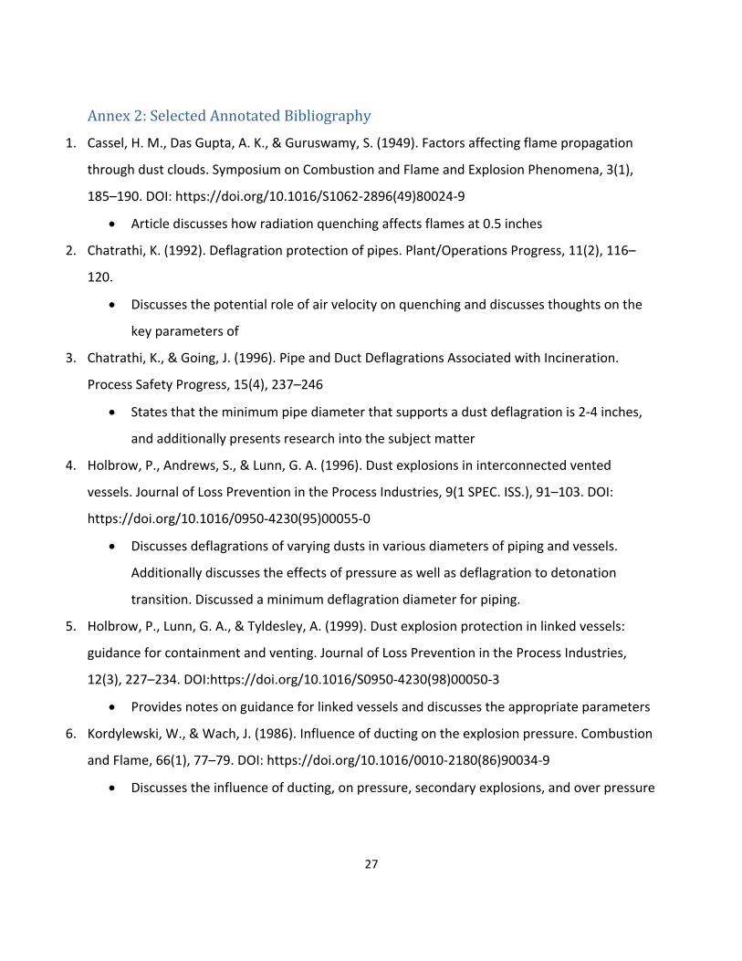
Annex 2: Selected Annotated Bibliography
1. Cassel, H. M., Das Gupta, A. K., & Guruswamy, S. (1949). Factors affecting flame propagation
through dust clouds. Symposium on Combustion and Flame and Explosion Phenomena, 3(1),
185–190. DOI: https://doi.org/10.1016/S1062-2896(49)80024-9
Article discusses how radiation quenching affects flames at 0.5 inches
2. Chatrathi, K. (1992). Deflagration protection of pipes. Plant/Operations Progress, 11(2), 116–
120.
Discusses the potential role of air velocity on quenching and discusses thoughts on the
key parameters of
3. Chatrathi, K., & Going, J. (1996). Pipe and Duct Deflagrations Associated with Incineration.
Process Safety Progress, 15(4), 237–246
States that the minimum pipe diameter that supports a dust deflagration is 2-4 inches,
and additionally presents research into the subject matter
4. Holbrow, P., Andrews, S., & Lunn, G. A. (1996). Dust explosions in interconnected vented
vessels. Journal of Loss Prevention in the Process Industries, 9(1 SPEC. ISS.), 91–103. DOI:
https://doi.org/10.1016/0950-4230(95)00055-0
Discusses deflagrations of varying dusts in various diameters of piping and vessels.
Additionally discusses the effects of pressure as well as deflagration to detonation
transition. Discussed a minimum deflagration diameter for piping.
5. Holbrow, P., Lunn, G. A., & Tyldesley, A. (1999). Dust explosion protection in linked vessels:
guidance for containment and venting. Journal of Loss Prevention in the Process Industries,
12(3), 227–234. DOI:https://doi.org/10.1016/S0950-4230(98)00050-3
Provides notes on guidance for linked vessels and discusses the appropriate parameters
6. Kordylewski, W., & Wach, J. (1986). Influence of ducting on the explosion pressure. Combustion
and Flame, 66(1), 77–79. DOI: https://doi.org/10.1016/0010-2180(86)90034-9
Discusses the influence of ducting, on pressure, secondary explosions, and over pressure

28
7. Kosinski, P., & Hoffmann, A. C. (2006). An investigation of the consequences of primary dust
explosions in interconnected vessels. Journal of Hazardous Materials, 137(2), 752–761.
DOI:https://doi.org/10.1016/j.jhazmat.2006.04.029
Discusses computational modeling of various dust parameters in relation to ignition and
propagation. Ignition chances go down with diameter. Quenching in terms of length and
diameter discussed as well.
8. Kosinski, P., & Hoffmann, A. C. (2005). Dust explosions in connected vessels: Mathematical
modelling. Powder Technology, 155(2), 108–116. DOI:
https://doi.org/10.1016/j.powtec.2005.05.052
Discusses channel height and its effect on an explosion in relation to secondary vessels
9. Lunn, G. A., Holbrow, P., Andrews, S., & Gummer, J. (1996). Dust explosions in totally enclosed
interconnected vessel systems. Journal of Loss Prevention in the Process Industries, 9(1 SPEC.
ISS.), 45–58. DOI: https://doi.org/10.1016/0950-4230(95)00052-6
Discusses flame propagation in piping in relation to the volume ratio. Diameter and
pressure parameters also discussed.
10. Matsuda, T., Toyonaga, K., Nozima, Y., Kobayashi, M., & Shimizu, T. (1982). Some Observations
on Dust Explosiblity in a Pneumatic Transport System. Journal of Power & Bulk Solids
Technology, 6(4), 22–28.
Discusses diameter effects on conveying velocity and the parameters of quenching
compared to conveying velocity.
11. Pineau, J. P., & Ronchaip, G. (1987). Propagation of Coal Dust Explosions in Pipes. Industrial
Dust Explosion, 74–89.
Discusses flame propagation in ducts conveying coal dust, discusses the parameters and
ignition strength in relation to the explosion potential.
12. Proust, C. (1996). Dust explosions in pipes: A review. Journal of Loss Prevention in the Process
Industries, 9(4), 267–277. DOI: https://doi.org/10.1016/0950-4230(96)00010-1
Discusses the stages of dust explosions in piping as well as in depth explanation of how
quenching diameter works. Other geometric configurations are also discussed.

29
13. Taveau, J. (2013). Dust explosion propagation: myths and realities.
DOI:https://doi.org/10.1016/j.jlp.2017.04.019
Discusses other literature that supports the idea that dust can propagate in piping less
than 4”.
14. Taveau, J. (2015). Dust Explosion Propagation through Small Diameter Pipes: A Review.
A presentation on the lack of technical substantiation for explosion isolation devices
being excluded from piping less than 4”.
15. Taveau, J. (2017). Dust explosion propagation and isolation. Journal of Loss Prevention in the
Process Industries, 48, 320–330. DOI: https://doi.org/10.1016/j.jlp.2017.04.019
Discusses compiled literature contesting that there is explosion propagation in piping
smaller than 4”.

30
Annex 3: Summary of Literature Review
Title (ref. #)
Author/s Relevance
1. T. Abbasi, S.A. Abbasi Dust Control
2. D.R. Ballal, A. H Lefebvre Correlation Between Dust and Mists
3. W. Barthnecht Dust Control
4. M. Bidabadi, S. Zadsirjan, S.A. Mostafavi Dust in Piping and Ductwork
5. M. Broumand, M. Bidabadi Dust in Piping and Ductwork
6. K. L. Cashdollar Dust Parameter Information
7. K. L. Cashdollar Dust Parameter Information
8. K. L. Cashdollar, I. A Zlochower Dust Parameter Information
9. H. M. Cassel, A.K. Das Gupta, S. Guruswamy Dust Parameter Information
10. H. M. Cassel Dust Parameter Information
11. K. Chatrathi Dust in Piping and Ductwork
12. K. Chatrathi, J. Going Dust in Piping and Ductwork
13. K. Chatrathi, J. Going Dust in Piping and Ductwork
14. K. Chatrathi, J. Going, B. Grandestaff Dust in Piping and Ductwork
15. C. Cintron, L. Claire Dust Control
16. C. Cloney Case Study
17. G. M. Colver, N. Greene, D. Shoemaker, S.W. Kim, T.U. Yu Dust Flame Quenching
18. M. G. Cooper, M. Fairweather, J.P Tite Dust in Piping and Ductwork
19. A. E. Dahoe Dust Parameter Information
20. A. Dastidar Dust Control
21. S. G. Davis, P. C. Hinze, O.R. Hansen, K. Van Wingerden Dust Control
22. A. Di Benedetto, P. Russo, P. Amyotte, N. Marchand Dust Parameter Information
23. R.K. Eckhoff Dust Parameter Information

31
24. R.K. Eckhoff Dust Parameter Information
25. R.K. Eckhoff Correlation Between Dusts and Gases
26. H. Febo Dust Control
27. H. Febo Dust Control
28. G. Ferrara, S. K. Willacy, H. N. Phylaktou, G.E Andrews, A. Di Benedetto, E. Salzano, G. Russo
Dust in Piping and Ductwork
29. W.L Frank, M.L. Holcomb Dust Control
30. H. Grosshans, M.V. Papalexandris Dust Parameter Information
31. P. Holbrow, S. Andrews, G.A. Lunn Dust in Piping and Ductwork
32. P. Holbrow, G.A. Lunn, A. Tyldesley Dust in Piping and Ductwork
33. P. Holbrow, G.A. Lunn, A. Tyldesley Dust in Piping and Ductwork
34. P. Holbrow, A. Tyldesley Dust in Piping and Ductwork
35. T. Hoppe, N. Jaeger, J. Terry Dust in Piping and Ductwork
36. N. Jaeger Dust in Piping and Ductwork
37. H. James Deflagration to Detonation Transition
38. I.D. Kashcheev Dust in Piping and Ductwork
39. C. Kersten, H. Förster Dust in Piping and Ductwork
40. W. Kordylewski, J. Wach Dust in Piping and Ductwork
41. P. Kosinski, A.C. Hoffmann Dust in Piping and Ductwork
42. P. Kosinski, A.C. Hoffmann Dust in Piping and Ductwork
43. M.A. Liberman, M.F. Ivanov, A.D. Kiverin, M.S. Kuznetsov, A.A. Chukalovsky, T.V. Rakhimova
Deflagration to Detonation Transition
44. Q. Liu, C. Bai, X. Li, L. Jiang, W. Dai Dust in Piping and Ductwork
45. Q. Liu, Y. Hu, C. Bai, M. Chen Dust in Piping and Ductwork
46. G.A. Lunn, G. A., Holbrow, P., Andrews, S., & Gummer, J Dust in Piping and Ductwork

32
47. T. Matsuda, K. Toyonaga, Y. Nozima, M. Kobayashi, T. Shimizu
Dust in Piping and Ductwork
48. M. Nifuku, H. Katoh Dust in Piping and Ductwork
49. OSHA Dust Control
50. H. Phylaktou, M. Foley, G.E. Andrews Dust in Piping and Ductwork
51. J.P. Pineau, G. Ronchaip Dust in Piping and Ductwork
52. B. Ponizy, Dust in Piping and Ductwork
53. B. Ponizy, B. Veyssiere Dust in Piping and Ductwork
54. C. Proust Dust in Piping and Ductwork
55. S. Rodgers, E.A. Ural Dust in Piping and Ductwork
56. T. Scherpa Dust Parameter Information
57. M. Silvestrini, B. Genova, G. Parisi, F.J. Leon Trujillo Dust in Piping and Ductwork
58. J.E. Going, J. Snoeys, J.R. Taveau Dust Control
59. B. Stevenson Dust in Piping and Ductwork
60. P. Štroch Dust Parameter Information
61. I. Swift Dust Control
62. F. Tamanini Dust Parameter Information
63. J. Taveau Dust Parameter Information
64. J. Taveau Dust Control
65. J. Taveau Dust in Piping and Ductwork
66. O.F. Theimer Dust in Piping and Ductwork
67. G. Thomas, G. Oakley, R. Bambrey Dust in Piping and Ductwork
68. U.S CSB Dust Control
69. U.S CSB Case Study
70. E.A. Ural Dust Parameter Information
71. Valiulis, J. V., Tamanini, F., & Zalosh, R Dust in Piping and Ductwork

33
72. A. Vogl Dust in Piping and Ductwork
73. A. Vogl Dust in Piping and Ductwork
74. J. B. Vorderbrueggen Case Study
75. H.C. Wu, Y.C. Kuo, Y. Heng Wang, C. W. Wu, H.C. Hsiao Dust in Piping and Ductwork
76. R. Zalosh Dust Control
References:
1. Abbasi, T., & Abbasi, S. A. (2007). Dust explosions-cases, causes, consequences, and control.
Journal of Hazardous Materials, 140(1–2), 7–44. DOI:
https://doi.org/10.1016/j.jhazmat.2006.11.007
2. Ballal, D. R., & Lefebvre, A. H. (1978). Ignition and Quenching of Quiescent Mists. The Royal
Society of London, 364(1717), 277–294.
3. Bartknecht, W. (1981). Explosions: Course Prevention Protection.
4. Bidabadi, M., Zadsirjan, S., & Mostafavi, S. A. (2013). Propagation and extinction of dust flames
in narrow channels. Journal of Loss Prevention in the Process Industries, 26(1), 172–176.
DOI:https://doi.org/10.1016/j.jlp.2012.10.009
5. Broumand, M., & Bidabadi, M. (2013). Modeling combustion of micron-sized iron dust particles
during flame propagation in a vertical duct. Fire Safety Journal, 59, 88–93.
DOI:https://doi.org/10.1016/j.firesaf.2013.04.009
6. Cashdollar, K. L. (1996). Coal dust explosibility. Journal of Loss Prevention in the Process
Industries, 9(1 SPEC. ISS.), 65–76. DOI: https://doi.org/10.1016/0950-4230(95)00050-X
7. Cashdollar, K. L. (2000). Overview of dust explosibility characteristics. Journal of Loss Prevention
in the Process Industries, 13(3–5), 183–199. DOI: https://doi.org/10.1016/S0950-
4230(99)00039-X
8. Cashdollar, K. L., & Zlochower, I. A. (2007). Explosion temperatures and pressures of metals and
other elemental dust clouds. Journal of Loss Prevention in the Process Industries, 20(4–6), 337–
348. DOI: https://doi.org/10.1016/j.jlp.2007.04.018

34
9. Cassel, H. M., Das Gupta, A. K., & Guruswamy, S. (1949). Factors affecting flame propagation
through dust clouds. Symposium on Combustion and Flame and Explosion Phenomena, 3(1),
185–190. DOI: https://doi.org/10.1016/S1062-2896(49)80024-9
10. Cassel, H. M. (1964). Some fundamental aspects of dust flames. Retrieved from
http://catalog.hathitrust.org/Record/005982043
11. Chatrathi, K. (1992). Deflagration protection of pipes. Plant/Operations Progress, 11(2), 116–
120.
12. Chatrathi, K., & Going, J. (2000). Dust deflagration extinction. Process Safety Progress, 19(3),
146–153. DOI: https://doi.org/10.1002/prs.680190305
13. Chatrathi, K., & Going, J. (1996). Pipe and Duct Deflagrations Associated with Incineration.
Process Safety Progress, 15(4), 237–246.
14. Chatrathi, K., Going, J. E., & Grandestaff, B. (2001). Flame Propagation in Industrial Scale Piping.
Process Safety Progress, 20(4), 286–294.
15. Cintron, C., & Claire, L. (1977). Explosionen - Ablauf und SchutzmaBnahmen. Chemie Ingenieur
Technik, 51(December), 346–357.
16. Cloney, C. (2016). 2016 Combustible Dust Incident Report (North America).
17. Colver, G. M., Greene, N., Shoemaker, D., Kim, S.W., & Yu, T.-U. (2004). Quenching dust
mixtures: A new microgravity testing method using electric particulate suspensions. AIAA
Journal, 42(10), 2092–2100. DOI: https://doi.org/10.1016/j.jlp.2005.06.035
18. Cooper, M. G., Fairweather, M., & Tite, J. P. (1986). On the mechanisms of pressure generation
in vented explosions. Combustion and Flame, 65(1), 1–14. DOI: https://doi.org/10.1016/0010-
2180(86)90067-2
19. Dahoe, A. E. (2000). Dust explosions: a Study of Flame Propagation.
20. Dastidar, A. (n.d.). PROCESS MODERNIZATION - Process Safety, Dust Explosion Hazards. Fauske
Associates.
21. Davis, S. G., Hinze, P. C., Hansen, O. R., & Van Wingerden, K. (2011). Does your facility have a
dust problem: Methods for evaluating dust explosion hazards. Journal of Loss Prevention in the
Process Industries, 24(6), 837–846. DOI: https://doi.org/10.1016/j.jlp.2011.06.010
22. Di Benedetto, A., Russo, P., Amyotte, P., & Marchand, N. (2010). Modelling the effect of particle
size on dust explosions. Chemical Engineering Science, 65(2), 772–779.
DOI:https://doi.org/10.1016/j.ces.2009.09.029

35
23. Eckhoff, R. K. (2009). Understanding dust explosions. The role of powder science and
technology. Journal of Loss Prevention in the Process Industries, 22(1), 105–116.
DOI:https://doi.org/10.1016/j.jlp.2008.07.006
24. Eckhoff, R. K. (1975). Towards absolute minimum ignition energies for dust clouds? Combustion
and Flame, 24(C), 53–64. DOI: https://doi.org/10.1016/0010-2180(75)90128-5
25. Eckhoff, R. K. (2006). Differences and similarities of gas and dust explosions: A critical evaluation
of the European “ATEX” directives in relation to dusts. Journal of Loss Prevention in the Process
Industries, 19(6), 553–560. DOI: https://doi.org/10.1016/j.jlp.2006.01.001
26. Febo, H (2011). Combustible Dust Hazard Recognition — An Insurer’s View, 30(1).
DOI:https://doi.org/10.1002/prs
27. Febo, H. (2011). Dryers – Processes & Protection.
28. Ferrara, G., Willacy, S. K., Phylaktou, H. N., Andrews, G. E., Di Benedetto, A., Salzano, E., & Russo,
G. (2008). Venting of gas explosion through relief ducts: Interaction between internal and
external explosions. Journal of Hazardous Materials, 155(1–2), 358–368.
DOI:https://doi.org/10.1016/j.jhazmat.2007.11.077
29. Frank, W. L., & Holcomb, M. L. (n.d.). Housekeeping Solutions, 10.
30. Grosshans, H., & Papalexandris, M. V. (2016). Evaluation of the parameters influencing
electrostatic charging of powder in a pipe flow. Journal of Loss Prevention in the Process
Industries, 43, 83–91. DOI:https://doi.org/10.1016/j.jlp.2016.05.002
31. Holbrow, P., Andrews, S., & Lunn, G. A. (1996). Dust explosions in interconnected vented
vessels. Journal of Loss Prevention in the Process Industries, 9(1 SPEC. ISS.), 91–103. DOI:
https://doi.org/10.1016/0950-4230(95)00055-0
32. Holbrow, P., Lunn, G. A., & Tyldesley, A. (2002). Explosion venting of bucket elevators. Journal of
Loss Prevention in the Process Industries, 15(5), 373–383. DOI: https://doi.org/10.1016/S0950-
4230(02)00021-9
33. Holbrow, P., Lunn, G. A., & Tyldesley, A. (1999). Dust explosion protection in linked vessels:
guidance for containment and venting. Journal of Loss Prevention in the Process Industries,
12(3), 227–234. DOI:https://doi.org/10.1016/S0950-4230(98)00050-3
34. Holbrow, P., & Tyldesley, A. (2003). Simple devices to prevent dust explosion propagation in
charge chutes and pipes. Journal of Loss Prevention in the Process Industries, 16(4), 333–340.
DOI:https://doi.org/10.1016/S0950-4230(03)00017-2

36
35. Hoppe, T., Jaeger, N., & Terry, J. (2000). Safe handling of combustible powders during
transportation, charging, discharging and storage. Journal of Loss Prevention in the Process
Industries, 13(3–5), 253–263. DOI: https://doi.org/10.1016/S0950-4230(99)00036-4
36. Jaeger, N. (2001). Safety strategy against potential hazards due to the handling of powders in a
blending unit. Journal of Loss Prevention in the Process Industries, 14(2), 139–151.
DOI:https://doi.org/10.1016/S0950-4230(00)00036-X
37. James, H. (2008). Basic Phenomenology of Deflagration, DDT, and Detonation. Retrieved from
papers://812ce4a6-6fe7-419f-b367-c6f9df4cc27d/Paper/p1049
38. Kashcheev, I. D. (2011). Pneumatic transport of explosive and hot bulk materials. Refractories
and Industrial Ceramics, 52(4), 23–27.
39. Kersten, C., & Förster, H. (2004). Investigation of deflagrations and detonations in pipes and
flame arresters by high-speed framing. Journal of Loss Prevention in the Process Industries,
17(1), 43–50. DOI:https://doi.org/10.1016/j.jlp.2003.09.004
40. Kordylewski, W., & Wach, J. (1986). Influence of ducting on the explosion pressure. Combustion
and Flame, 66(1), 77–79. DOI: https://doi.org/10.1016/0010-2180(86)90034-9
41. Kosinski, P., & Hoffmann, A. C. (2006). An investigation of the consequences of primary dust
explosions in interconnected vessels. Journal of Hazardous Materials, 137(2), 752–761.
DOI:https://doi.org/10.1016/j.jhazmat.2006.04.029
42. Kosinski, P., & Hoffmann, A. C. (2005). Dust explosions in connected vessels: Mathematical
modelling. Powder Technology, 155(2), 108–116. DOI:
https://doi.org/10.1016/j.powtec.2005.05.052
43. Liberman, M. A., Ivanov, M. F., Kiverin, A. D., Kuznetsov, M. S., Chukalovsky, A. A., & Rakhimova,
T. V. (2010). Deflagration-to-detonation transition in highly reactive combustible mixtures. Acta
Astronautica, 67(7–8), 688–701. DOI: https://doi.org/10.1016/j.actaastro.2010.05.024
44. Liu, Q., Bai, C., Li, X., Jiang, L., & Dai, W. (2010). Coal dust/air explosions in a large-scale tube.
Fuel, 89(2), 329–335. DOI: https://doi.org/10.1016/j.fuel.2009.07.010
45. Liu, Q., Hu, Y., Bai, C., & Chen, M. (2013). Methane/coal dust/air explosions and their
suppression by solid particle suppressing agents in a large-scale experimental tube. Journal of
Loss Prevention in the Process Industries, 26(2), 310–316. DOI:
https://doi.org/10.1016/j.jlp.2011.05.004

37
46. Lunn, G. A., Holbrow, P., Andrews, S., & Gummer, J. (1996). Dust explosions in totally enclosed
interconnected vessel systems. Journal of Loss Prevention in the Process Industries, 9(1 SPEC.
ISS.), 45–58. DOI: https://doi.org/10.1016/0950-4230(95)00052-6
47. Matsuda, T., Toyonaga, K., Nozima, Y., Kobayashi, M., & Shimizu, T. (1982). Some Observations
on Dust Explosiblity in a Pneumatic Transport System. Journal of Power & Bulk Solids
Technology, 6(4), 22–28.
48. Nifuku, M., & Katoh, H. (2003). A study on the static electrification of powders during pneumatic
transportation and the ignition of dust cloud. Powder Technology, 135–136, 234–242.
DOI:https://doi.org/10.1016/S0032-5910(03)00163-3
49. OSHA. (2010). Combustible Dust : Awareness Training Program.
50. Phylaktou, H., Foley, M., & Andrews, G. E. (1993). Explosion enhancement through a 90o curved
bend. Journal of Loss Prevention in the Process Industries, 6(1), 21–29. DOI:
https://doi.org/10.1016/0950-4230(93)80016-F
51. Pineau, J. P., & Ronchaip, G. (1987). Propagation of Coal Dust Explosions in Pipes. Industrial Dust
Explosion, 74–89.
52. Ponizy, B. (1999). Flame dynamics in a vented vessel connected to a duct. Part 1 Mechanism of
vessel-duct interaction. Combustion and Flame, 116, 259–271.
53. Ponizy, B., & Veyssiere, B. (2000). Mitigation of Explosions in a Vented Vessel Connected to a
Duct. Combustion Science and Technology, 158(1), 167–182.
DOI:https://doi.org/10.1080/00102200008947332
54. Proust, C. (1996). Dust explosions in pipes: A review. Journal of Loss Prevention in the Process
Industries, 9(4), 267–277. DOI: https://doi.org/10.1016/0950-4230(96)00010-1
55. Rodgers, S., & Ural, E. A. (2011). Practical Issues with Marginally Explosible Dusts - Evaluating the
Real Hazard. Process Safety Progress, 30(3), 266–279. https://doi.org/10.1002/prs
56. Scherpa, T. (2002). Secondary Dust Cloud Formation from an Initiating Blast Wave. Worcester
Polytechnic Institute.
57. Silvestrini, M., Genova, B., Parisi, G., & Leon Trujillo, F. J. (2008). Flame acceleration and DDT
run-up distance for smooth and obstacles filled tubes. Journal of Loss Prevention in the Process
Industries, 21(5), 555–562. DOI: https://doi.org/10.1016/j.jlp.2008.05.002

38
58. Going, J. E., Snoeys, J., & Taveau, J. R. (2012). Advances in dust explosion protection techniques:
Flameless venting. Procedia Engineering, 45, 403–413.
DOI:https://doi.org/10.1016/j.proeng.2012.08.178
59. Stevenson, B. (2015). How to prevent or mitigate a dust explosion in your bucket elevator.
60. Štroch, P. (2016). Do not underestimate danger of explosion; even dust can destroy equipment
and kill. Perspectives in Science, 7, 312–316. DOI: https://doi.org/10.1016/j.pisc.2015.11.048
61. Swift, I. (1984). Venting Deflagrations Theory and Practice.pdf. Plant/Operations Progress, 3(2),
89–93.
62. Tamanini, F. (1998). The role of turbulence in dust explosions. Journal of Loss Prevention in the
Process Industries, 11(1), 1–10. DOI: https://doi.org/10.1016/S0950-4230(97)00026-0
63. Taveau, J. (2013). Dust explosion propagation: myths and realities.
DOI:https://doi.org/10.1016/j.jlp.2017.04.019
64. Taveau, J. (2014). Application of Dust explosion protection systems. Procedia Engineering, 84,
297–305. DOI: https://doi.org/10.1016/j.proeng.2014.10.438
65. Taveau, J. (2015). Dust Explosion Propagation through Small Diameter Pipes: A Review.
66. Theimer, O. F. (1973). Cause and prevention of dust explosions in grain elevators and flour mills.
Powder Technology, 8(3–4), 137–147. DOI: https://doi.org/10.1016/0032-5910(73)80076-2
67. Thomas, G., Oakley, G., & Bambrey, R. (2010). An experimental study of flame acceleration and
deflagration to detonation transition in representative process piping. Process Safety and
Environmental Protection, 88(2), 75–90. DOI: https://doi.org/10.1016/j.psep.2009.11.008
68. U.S. CSB. (2010). Investigation Report, COMBUSTIBLE DUST HAZARD STUDY. U. S. Chemical
Safety and Hazard Investigation Board. https://doi.org/REPORT NO. 2006-H-1
69. U.S. CSB. (2005). INVESTIGATION REPORT, Aluminum Dust Explosion. U. S. Chemical Safety and
Hazard Investigation Board. Huntington, Indiana.
70. Ural, E. A., & Science, L. P. (2011). Towards Estimating Entrainment Fraction For Dust Layers.
71. Valiulis, J. V., Tamanini, F., & Zalosh, R. (1999). Experiments on the propagation of vented dust
explosions to connected equipment. Process Safety Progress, 18(2), 99–106.
DOI:https://doi.org/10.1002/prs.680180209
72. Vogl, A. (1996). Flame propagation in pipes of pneumatic conveying systems and exhaust
equipment. Process Safety Progress, 15(4), 219–226. DOI:
https://doi.org/10.1002/prs.680150408

39
73. Vogl, A. (n.d.). Vogl_Explosion propagation through thin pipes_GERMAN.pdf.
74. Vorderbrueggen, J. B. (2011). Imperial Sugar Refinery Combustible Dust Explosion Investigation.
Process Safety Progress, 30(1), 66–81. DOI: https://doi.org/10.1002/prs
75. Wu, H. C., Kuo, Y. C., Wang, Y. Heng, Wu, C. W., & Hsiao, H. C. (2010). Study on safe air
transporting velocity of nanograde aluminum, iron, and titanium. Journal of Loss Prevention in
the Process Industries, 23(2), 308–311. https://doi.org/10.1016/j.jlp.2009.11.002
76. Zalosh, R. (2004). Dust Explosion Fundamentals: Ignition Criteria and Pressure Development.
Paragraph, 1(2003).